US7349102B2 - Methods and apparatus for reducing error in interferometric imaging measurements - Google Patents
Methods and apparatus for reducing error in interferometric imaging measurementsDownload PDFInfo
- Publication number
- US7349102B2 US7349102B2US11/622,304US62230407AUS7349102B2US 7349102 B2US7349102 B2US 7349102B2US 62230407 AUS62230407 AUS 62230407AUS 7349102 B2US7349102 B2US 7349102B2
- Authority
- US
- United States
- Prior art keywords
- fringe
- diffractive element
- light source
- broadband
- generator
- Prior art date
- Legal status (The legal status is an assumption and is not a legal conclusion. Google has not performed a legal analysis and makes no representation as to the accuracy of the status listed.)
- Expired - Lifetime
Links
- 238000005259measurementMethods0.000titleclaimsabstractdescription15
- 238000000034methodMethods0.000titledescription24
- 238000003384imaging methodMethods0.000titledescription17
- 230000003595spectral effectEffects0.000claimsabstractdescription11
- 230000008859changeEffects0.000claimsabstractdescription10
- 230000003287optical effectEffects0.000claimsdescription12
- 238000013519translationMethods0.000claimsdescription8
- 230000000295complement effectEffects0.000claims2
- 230000010363phase shiftEffects0.000claims2
- 230000001902propagating effectEffects0.000claims2
- 239000011295pitchSubstances0.000description16
- 230000008901benefitEffects0.000description4
- 238000013459approachMethods0.000description3
- 230000001419dependent effectEffects0.000description3
- 230000008569processEffects0.000description3
- 230000001427coherent effectEffects0.000description2
- 238000013461designMethods0.000description2
- 238000011161developmentMethods0.000description2
- 238000005516engineering processMethods0.000description2
- 238000005286illuminationMethods0.000description2
- 239000000463materialSubstances0.000description2
- 230000005855radiationEffects0.000description2
- 230000009467reductionEffects0.000description2
- 239000000758substrateSubstances0.000description2
- 238000004458analytical methodMethods0.000description1
- 230000015572biosynthetic processEffects0.000description1
- 230000015556catabolic processEffects0.000description1
- 239000000470constituentSubstances0.000description1
- 230000002596correlated effectEffects0.000description1
- 230000000875corresponding effectEffects0.000description1
- 230000003247decreasing effectEffects0.000description1
- 238000006731degradation reactionMethods0.000description1
- 238000002050diffraction methodMethods0.000description1
- 230000000694effectsEffects0.000description1
- 230000003993interactionEffects0.000description1
- 230000000116mitigating effectEffects0.000description1
- 239000000203mixtureSubstances0.000description1
- 238000012544monitoring processMethods0.000description1
- 238000007670refiningMethods0.000description1
- 238000011160researchMethods0.000description1
- 238000000926separation methodMethods0.000description1
- 238000012800visualizationMethods0.000description1
- 201000009482yawsDiseases0.000description1
Images


Classifications
- G—PHYSICS
- G01—MEASURING; TESTING
- G01D—MEASURING NOT SPECIALLY ADAPTED FOR A SPECIFIC VARIABLE; ARRANGEMENTS FOR MEASURING TWO OR MORE VARIABLES NOT COVERED IN A SINGLE OTHER SUBCLASS; TARIFF METERING APPARATUS; MEASURING OR TESTING NOT OTHERWISE PROVIDED FOR
- G01D5/00—Mechanical means for transferring the output of a sensing member; Means for converting the output of a sensing member to another variable where the form or nature of the sensing member does not constrain the means for converting; Transducers not specially adapted for a specific variable
- G01D5/26—Mechanical means for transferring the output of a sensing member; Means for converting the output of a sensing member to another variable where the form or nature of the sensing member does not constrain the means for converting; Transducers not specially adapted for a specific variable characterised by optical transfer means, i.e. using infrared, visible, or ultraviolet light
- G01D5/32—Mechanical means for transferring the output of a sensing member; Means for converting the output of a sensing member to another variable where the form or nature of the sensing member does not constrain the means for converting; Transducers not specially adapted for a specific variable characterised by optical transfer means, i.e. using infrared, visible, or ultraviolet light with attenuation or whole or partial obturation of beams of light
- G01D5/34—Mechanical means for transferring the output of a sensing member; Means for converting the output of a sensing member to another variable where the form or nature of the sensing member does not constrain the means for converting; Transducers not specially adapted for a specific variable characterised by optical transfer means, i.e. using infrared, visible, or ultraviolet light with attenuation or whole or partial obturation of beams of light the beams of light being detected by photocells
- G01D5/36—Forming the light into pulses
- G01D5/38—Forming the light into pulses by diffraction gratings
- G—PHYSICS
- G01—MEASURING; TESTING
- G01B—MEASURING LENGTH, THICKNESS OR SIMILAR LINEAR DIMENSIONS; MEASURING ANGLES; MEASURING AREAS; MEASURING IRREGULARITIES OF SURFACES OR CONTOURS
- G01B11/00—Measuring arrangements characterised by the use of optical techniques
- G01B11/24—Measuring arrangements characterised by the use of optical techniques for measuring contours or curvatures
- G01B11/25—Measuring arrangements characterised by the use of optical techniques for measuring contours or curvatures by projecting a pattern, e.g. one or more lines, moiré fringes on the object
- G01B11/254—Projection of a pattern, viewing through a pattern, e.g. moiré
Definitions
- the present inventionrelates generally to the field of imaging technology and, more specifically, to three-dimensional imaging methods and devices.
- Measuring the characteristics of an object and generating a three dimensional representation of the object from acquired sensor dataare central objectives in the field of metrology.
- the continuing development of various techniques to achieve these objectivesis often grounded in using interferometric principles to obtain precise measurement data.
- refining and improving upon existing approachesrepresents a valuable and necessary contribution to modern day research efforts.
- the present inventionprovides a method and apparatus for reducing error in interferometric fringe stability and reproducibility in an interference fringe generator.
- the method for reducing error in interferometric fringe stability and reproductivityincludes providing a light source, positioning a grating to receive light from the light source and positioning a projection lens having a focal length F to receive light from the grating.
- the projection lensprojects the received light upon an object of interest positioned substantially at a distance d 1 from the lens.
- the lensis positioned substantially at a distance d 2 from the grating.
- the values of d 1 , d 2 , and Fare related by d 2 being approximately equal to d 1 F/(d 1 ⁇ F).
- fringe projector and fringe generatorare used interchangeably throughout the application.
- Such devicesalone or in combination with other components cause the formation of interference fringes in space.
- Such fringesare typically generated or projected upon the surface of an object of interest.
- These devicesdiffer from standard image projectors that do not utilize interference principles.
- the inventionin another aspect, relates to an optical system for reducing error in interferometric fringe stability and reproducibility in an interference fringe generator.
- the systemtypically includes a light source, a grating positioned to receive light from the light source and a lens for projecting fringes having a focal length F.
- the lensis positioned to receive light from the grating and to project the received light upon an object of interest positioned substantially at a distance d 1 from the lens.
- the lensis positioned substantially at a distance d 2 from the grating.
- the values of d 1 , d 2 , and Fare related by d 2 being approximately equal to d 1 F/(d 1 ⁇ F).
- the light sourceis a coherent light source such as a laser.
- an acousto-optical modulator or other diffractive elementis used in lieu of a grating.
- the inventionin another aspect, relates to a method for reducing errors in positional information obtained from a translatable grating in an interference fringe generator.
- the methodincludes positioning a translatable grating substantially defining a first plane within a fringe projector. Positioning an encoder scale defining a second plane substantially orthogonal to the first plane directly over the grating is another step in the method.
- the methodalso includes measuring the relative motion of the grating with respect to the encoder scale.
- the grating and encoder scaleare manufactured on the same substrate.
- the grating and encoder scaleare made from the same material.
- the encoder read-headis aligned with the optical axis of the system's projection lens.
- the inventionin yet another aspect, relates to a method for reducing errors in positional information obtained from a translatable grating in an interference fringe generator.
- the methodincludes positioning a translatable grating substantially defining a first plane within a fringe projector.
- the methodalso includes positioning two encoder scales substantially parallel to the first plane at positions above and below the grating. Measuring the relative motion of the grating with respect to the encoder scales and using differential information from the relative motion of the grating with respect to the encoder scales to reduce pitch based errors are also steps in the disclosed method.
- FIG. 1is a schematic representation of an embodiment of a portion of an interference fringe generating system in accordance with the teachings of the invention
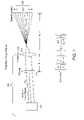
- FIG. 2illustrates an embodiment of an interference-fringe projector suitable for use with various aspects of the invention
- FIG. 3illustrates the characteristics of a diffraction grating suitable for use with various aspects of the invention.
- FIGS. 4A and 4Bare schematic representations of differing measurement system configurations that illustrate various techniques and approaches for reducing measurement error in accordance with the teachings of the invention.
- interference principlesform the underlying basis upon which the application or system operates.
- two point sources of lightare employed to produce interference fringes.
- coherent lightis used, such as for example a laser.
- These two point sourcesmay derive from an original source that was previously split or otherwise modified by an arrangement of one or more optical elements, such as a diffractive element.
- optical elementssuch as a diffractive element.
- light from the two point sourcesis directed and manipulated such that it expands and overlaps.
- controlled sinusoidal fringesalso known as accordion fringes, are produced throughout space.
- fringesAs the generation of these fringes is controlled, various parameters regarding the fringes as well as the apparatus and methods which produced them are known. Thus, when the fringes impinge on an object, surface profile and dimensional information about that object may be calculated after the fact. In one embodiment this is achieved by imaging the fringes, typically with a detector such as a conventional camera or CCD array, optionally changing the fringes according to a prescribed process, and finally calculating point cloud information about the object. From this it is clear that the positional stability and repeatability of the fringes is important when making high quality measurements.
- the inventionis directed to both apparatus and methods for mitigating the effects of light source angular movement that contribute to undesirable fringe pattern motion.
- FIG. 1shows a schematic representation of the fringe generating portion 100 of an imagining device.
- the fringe generating portion 100includes a light source 105 , a diffractive element, shown as grating 110 , and a projection lens 115 .
- the projection lens 115has a focal length F and the grating has a period T.
- a grating 110is shown in this embodiment, other diffractive elements can be used instead, such as an acousto-optical modulator.
- the optical axis 117 of the projection lens 115is designated by the dotted line shown.
- the incident angle of the system's light source 105shown here as a laser, with respect to the optical axis 117 of the projection lens is ⁇ .
- the longitudinal separation between the grating 110 and projection lens 115is d 2 and the distance between the projection lens and the region of measurement 120 for the object of interest is d 1 .
- I ⁇ ( x )cos 2 ⁇ [ 2 ⁇ ⁇ T ⁇ ⁇ ( F d 1 - F ) ⁇ x - ( d 2 - d 1 ⁇ F d 1 - F ) ⁇ ⁇ ⁇ ] It is noteworthy that as ⁇ changes, the phase of the sinusoidal fringe pattern changes. In other words, the position of the sinusoidal fringe pattern is a function of the incident angle of the laser beam, ⁇ , in the system. This angular dependence of the fringe pattern can be eliminated by proper choice of the distances d 1 and d 2 for a given projection lens 115 focal length F.
- any angular movement of the laser beam 105 that impinges on the gratingwill not result in fringe pattern motion. Eliminating errors introduced by light source 105 motion will in turn improve metrology and imaging data quality in various types of systems and devices using fringe generation based techniques.
- Light source 250generates a substantially collimated beam of radiation 252 that is directed to translatable diffraction grating 254 at substantially normal incidence before passing to projection lens 266 .
- the aspects of the invention discussed above in relation to FIG. 1are directly applicable to the source 250 , grating 254 , lens 266 arrangement substantially at positions d 1 and d 2 as shown in this embodiment.
- fringe-generation scheme depicted in FIG. 2can also produce fringes using narrow-band or laser illumination while incorporating the features of the invention discussed in relation to FIG. 1 .
- One advantage of using diffraction grating 254 followed by lens 266 for narrow-band illuminationis that fringe period d is insensitive to wavelength so that frequency drifts of the source do not substantially degrade measurements.
- laser diodesare relatively inexpensive and readily available sources, they have a temperature-dependent operating wavelength. However, since this technique is insensitive to temperature-dependent wavelength shifts, laser diodes can be used without measurement degradation.
- diffraction grating 254is shown with grating period D.
- Input beam 252is represented by three constituent wavelength components ⁇ 1 , ⁇ 2 , and ⁇ 3 for illustration.
- Beam 252in actuality, can have arbitrary spectral composition.
- Diffraction grating 254splits beam 252 into multiple diffracted beams whose diffraction orders can be represented by the integer m. For illustration purposes, only rays along the perimeter of beam 252 are shown. These diffracted beams propagate at angles ⁇ m with respect to the optical axis 258 according to the grating equation for normal incidence, which is given by:
- , and to minimize the energy diffracted into all other orders. Any residual undiffracted (m0) beam 264 , will pass undeviated through diffraction grating 254 and is focused by projection lens 266 onto focal spot 268 .
- the spectral components ⁇ 1 , ⁇ 2 , and ⁇ 3 of focal spot 268substantially overlap.
- Focal spot 268may be substantially blocked by the central obstruction 270 of optional double slit 272 .
- the different spectral components ⁇ 1 , ⁇ 2 , and ⁇ 3 of diffracted beams 260 and 262are focused by lens 266 onto spectral regions 274 and 276 .
- the distance ⁇ ( ⁇ ) between the focal spot within spectral region 274 and the focal spot within spectral region 276 corresponding to a given wavelength ⁇is substantially proportional to the wavelength ⁇ .
- Aperture stop 278 of lens 266in one embodiment, can be used to block undesired higher-order diffracted beams.
- the aperture stopis not used. Any undesired residual diffracted orders that pass through lens 266 can be blocked, in another embodiment, by the opaque regions of optional double slit 272 . Radiation from the two spectral regions 274 and 276 expands and overlaps as it propagates and forms an interference-fringe pattern 280 . Fringe pattern 280 has representative fringe period d at representative distance R from double slit 272 .
- Phase shifting the resulting broadband (or narrow-brand) interference-fringe pattern 280is achieved by simply translating diffraction grating 254 in the direction 282 shown in FIG. 2 .
- White-light or broadband phase shiftingis realized because a translation of diffraction grating 254 by a given fraction of the grating period D shifts each spectral component of fringe pattern 280 by twice the same fraction of the fringe period d.
- a translation of grating 252 by D/4, or one-quarter cyclealso shifts the interference-fringe pattern 280 by one-half cycle.
- Accordion motion (or variation of fringe size) of interference-fringe pattern 280can be achieved in a number of ways.
- doubling the period D of grating 254halves the magnitude of ⁇ m of beams 260 and 262 which in turn doubles the period d of fringe pattern 280 .
- decreasing the focal length f of lens 266can increase the period d of fringe pattern 280 .
- the placement of the lens, grating, and object of interest as taught hereincontributes to producing fringe stability and reproducibility.
- Another aspect of the inventionrelates to reducing the error when fringe motion is caused by design in a controlled fashion as part of the process of imaging an object.
- One of the operational features in various fringe generating imaging systemsinvolves precisely translating a grating over specified distances. In some embodiments these translation distances are approximately 50 mm. Generally, the only limitations on translation distance are a function of a given imaging system set up and the size of the diffraction grating. In various embodiments, the accuracy with which the lateral position of the grating needs to be known is approximately 1/10 of a micrometer. In general various aspects of the invention relate to accurately knowing the position of the grating because the position of the projected fringes is directly correlated with the position of the grating. This is discussed above in relation to translatable grating 254 in FIG. 2 .
- FIG. 3schematically illustrates a grating 110 ′ and an encoder scale 300 according to an embodiment of the invention.
- the discussion of grating 110 ′ shown in FIG. 2also applies to the grating 110 in FIG. 1 and the grating 254 in FIG. 2 .
- the discussion of FIGS. 3 , 4 A and 4 Bapplies to those embodiments wherein a grating is translated to change the characteristics of a fringe pattern as part of an imaging or metrology system.
- a commercial linear encodercan be used to determine the position of the grating ( 110 , 110 ′, 254 ).
- Other types of measurement devices employing fixed scales and devices for reading those scalescan also be used in other embodiments.
- the linear encoderoperates by monitoring the position of an encoder scale 300 with an encoder read-head (not shown).
- One of the largest sources of error that is typically encountered when using a linear encoderis Abbé error. Abbé error occurs when the spatial position of interest is displaced from the true position recorded by the measuring system. This in turn results in the introduction of errors in any system using the data generated by the measuring system.
- Abbé erroris encountered when the object for which positional information is sought (in our case the grating 110 ′) is not at the same location as the position measuring device.
- this measuring deviceis a linear encoder read-head. As the object (grating 110 ′) is translated, any relative angular changes between the measuring device and the grating 110 ′ will result in Abbé error.
- the position 305 on the encoder scale 300represents the location where the encoder read-head is making a position measurement.
- the position 310 on the grating 110 ′represents the location that must be tracked and measured to obtain overall grating positional information.
- the grating 110 ′ and encoder scale 300are rigidly coupled 1 and are translated by a motorized stage (not shown) along the stage travel axis shown in the FIG. 3 .
- the grating 110 ′ and encoder scale 305both incur small angular rotations due to imperfections in the stage. Two of these angular rotations, pitch and yaw, will introduce Abbé error.
- FIGS. 4A and 4Billustrate some techniques according to the invention for reducing Abbé error.
- Configuration 1 shown in FIG. 4Ais applicable to various gratings such as the one shown in FIG. 3 .
- the encoder scaleis mounted perpendicular to the grating and directly over it. This configuration typically eliminates the yaw component of the Abbé error, and minimizes the pitch component. Note that the pitch component is not completely eliminated, because the encoder scale cannot occlude the grating if the system is to operate properly.
- the encoder read-headis aligned with the optical axis of the system's projection lens.
- the grating 110 ′ and encoder scale 300are fabricated from the same materials to facilitate a reduction of temperature-based errors. These two system aspects eliminate imaging system errors that would otherwise be present due to temperature changes in the various imaging and metrology systems.
- Configuration 1 in FIG. 4Adoes not completely eliminate the Abbé error due to stage pitch.
- Another proposed implementationmay eliminate or substantially reduce the Abbé error due to pitch.
- This configurationuses two linear encoder scales 300 A, 300 B (and one or more measuring devices, typically two encoder read-heads). The measurement scales are positioned with one above and one below the grating 110 ′ as shown. Knowing the relative positions of the two read-heads with respect to the grating 110 ′, it is possible to take the two readings from the two encoders 300 A, 300 B and calculate the pitch error at the grating center. This type of differential measuring enables differences between the two encoder scales readings to facilitate a determination of pitch error.
- a processorsuch as a computer processor or logic circuit, carries out the pitch error and yaw error calculations.
- the encoder scales 300 A, 300 Blie in the same plane as the grating 110 ′, so that the yaw error is approximately zero.
- the encoder scales and gratingsare fabricated on a single substrate in various embodiments. This provides improved alignment and enhanced thermal stability. Further error reduction can be achieved by combining the general aspects of the invention relating to encoder scale and optical element positioning in one device or measurement system.
Landscapes
- Physics & Mathematics (AREA)
- General Physics & Mathematics (AREA)
- Engineering & Computer Science (AREA)
- Computer Vision & Pattern Recognition (AREA)
- Length Measuring Devices By Optical Means (AREA)
- Optical Transform (AREA)
- Instruments For Measurement Of Length By Optical Means (AREA)
Abstract
Description
It is noteworthy that as θ changes, the phase of the sinusoidal fringe pattern changes. In other words, the position of the sinusoidal fringe pattern is a function of the incident angle of the laser beam, θ, in the system. This angular dependence of the fringe pattern can be eliminated by proper choice of the distances d1and d2for a given
Rearranging this equation, results in the following lens formula relationship:
Thus, this algebraic manipulation reveals that the θ dependence of the system will be eliminated if the system is set-up such that the
Claims (15)
Priority Applications (1)
| Application Number | Priority Date | Filing Date | Title |
|---|---|---|---|
| US11/622,304US7349102B2 (en) | 2003-06-18 | 2007-01-11 | Methods and apparatus for reducing error in interferometric imaging measurements |
Applications Claiming Priority (3)
| Application Number | Priority Date | Filing Date | Title |
|---|---|---|---|
| US47953403P | 2003-06-18 | 2003-06-18 | |
| US10/871,878US7184149B2 (en) | 2003-06-18 | 2004-06-18 | Methods and apparatus for reducing error in interferometric imaging measurements |
| US11/622,304US7349102B2 (en) | 2003-06-18 | 2007-01-11 | Methods and apparatus for reducing error in interferometric imaging measurements |
Related Parent Applications (1)
| Application Number | Title | Priority Date | Filing Date |
|---|---|---|---|
| US10/871,878DivisionUS7184149B2 (en) | 2003-06-18 | 2004-06-18 | Methods and apparatus for reducing error in interferometric imaging measurements |
Publications (2)
| Publication Number | Publication Date |
|---|---|
| US20070109556A1 US20070109556A1 (en) | 2007-05-17 |
| US7349102B2true US7349102B2 (en) | 2008-03-25 |
Family
ID=33551893
Family Applications (2)
| Application Number | Title | Priority Date | Filing Date |
|---|---|---|---|
| US10/871,878Expired - LifetimeUS7184149B2 (en) | 2003-06-18 | 2004-06-18 | Methods and apparatus for reducing error in interferometric imaging measurements |
| US11/622,304Expired - LifetimeUS7349102B2 (en) | 2003-06-18 | 2007-01-11 | Methods and apparatus for reducing error in interferometric imaging measurements |
Family Applications Before (1)
| Application Number | Title | Priority Date | Filing Date |
|---|---|---|---|
| US10/871,878Expired - LifetimeUS7184149B2 (en) | 2003-06-18 | 2004-06-18 | Methods and apparatus for reducing error in interferometric imaging measurements |
Country Status (3)
| Country | Link |
|---|---|
| US (2) | US7184149B2 (en) |
| EP (1) | EP1644699B1 (en) |
| WO (1) | WO2005001774A2 (en) |
Cited By (1)
| Publication number | Priority date | Publication date | Assignee | Title |
|---|---|---|---|---|
| US20160131882A1 (en)* | 2014-11-11 | 2016-05-12 | California Institute Of Technology | Common-mode digital holographic microscope |
Families Citing this family (6)
| Publication number | Priority date | Publication date | Assignee | Title |
|---|---|---|---|---|
| US7751063B2 (en)* | 2005-04-06 | 2010-07-06 | Dimensional Photonics International, Inc. | Multiple channel interferometric surface contour measurement system |
| DK2211696T3 (en)* | 2007-11-01 | 2019-03-18 | Dental Imaging Technologies Corp | INTRAORAL THREE-DIMENSIONAL IMAGE SYSTEM |
| US20120008150A1 (en)* | 2010-04-23 | 2012-01-12 | Nikon Corporation | Autofocus system and method |
| TWI546518B (en)* | 2012-04-20 | 2016-08-21 | 德律科技股份有限公司 | Three dimensional measurement system and three dimensional measurement method |
| CN104331978B (en) | 2014-11-19 | 2017-02-01 | 广州广电运通金融电子股份有限公司 | Recognition device and method for fold of paper currency |
| CN115199152B (en)* | 2021-04-09 | 2023-09-15 | 南京工业大学 | An intelligent password lock based on grating diffraction |
Citations (9)
| Publication number | Priority date | Publication date | Assignee | Title |
|---|---|---|---|---|
| US4498770A (en)* | 1979-05-29 | 1985-02-12 | Beta Industries, Inc. | Apparatus and method for determining the configuration of a reflective surface |
| US5835218A (en)* | 1995-07-18 | 1998-11-10 | Insutrial Technology Institute | Moire interferometry system and method with extended imaging depth |
| US20020135773A1 (en)* | 2001-03-20 | 2002-09-26 | Chen Fang Frank | Crystal based fringe generator system |
| US6541761B1 (en)* | 1999-08-31 | 2003-04-01 | Dr. Johannas Heidenhain Gmbh | Optical position measuring system with a graduation that causes essentially only first orders of diffraction |
| US20030160969A1 (en)* | 2000-03-30 | 2003-08-28 | Junji Endo | Interference measuring device |
| US6690474B1 (en)* | 1996-02-12 | 2004-02-10 | Massachusetts Institute Of Technology | Apparatus and methods for surface contour measurement |
| US6817528B2 (en)* | 2001-07-17 | 2004-11-16 | Honeywell International Inc. | Reflective apparatus and method for optically sensing relative torque employing Moirè fringes |
| US20060044569A1 (en)* | 2004-09-02 | 2006-03-02 | Canon Kabushiki Kaisha | Apparatus for measuring optical properties of tested optical system using interference |
| US20060072122A1 (en)* | 2004-09-30 | 2006-04-06 | Qingying Hu | Method and apparatus for measuring shape of an object |
Family Cites Families (19)
| Publication number | Priority date | Publication date | Assignee | Title |
|---|---|---|---|---|
| US6560018B1 (en)* | 1994-10-27 | 2003-05-06 | Massachusetts Institute Of Technology | Illumination system for transmissive light valve displays |
| US5610719A (en)* | 1995-07-10 | 1997-03-11 | Qc Optics, Inc. | Displacement detection system |
| US5811826A (en) | 1996-02-07 | 1998-09-22 | Massachusetts Institute Of Technology | Methods and apparatus for remotely sensing the orientation of an object |
| US6229619B1 (en) | 1996-02-12 | 2001-05-08 | Massachusetts Institute Of Technology | Compensation for measurement uncertainty due to atmospheric effects |
| US5870191A (en) | 1996-02-12 | 1999-02-09 | Massachusetts Institute Of Technology | Apparatus and methods for surface contour measurement |
| US6031612A (en) | 1996-02-12 | 2000-02-29 | Massachusetts Institute Of Technology | Apparatus and methods for contour measurement using movable sources |
| US5900936A (en) | 1996-03-18 | 1999-05-04 | Massachusetts Institute Of Technology | Method and apparatus for detecting relative displacement using a light source |
| US6956963B2 (en) | 1998-07-08 | 2005-10-18 | Ismeca Europe Semiconductor Sa | Imaging for a machine-vision system |
| DE19845145A1 (en) | 1998-10-01 | 2000-04-06 | Hydac Process Technology Gmbh | Process for making a seal |
| DE19846145A1 (en)* | 1998-10-01 | 2000-04-20 | Klaus Koerner | Three-dimensional imaging device for shape measurement has transmitter array whose elements move in straight, parallel lines |
| US6084712A (en)* | 1998-11-03 | 2000-07-04 | Dynamic Measurement And Inspection,Llc | Three dimensional imaging using a refractive optic design |
| US6259561B1 (en) | 1999-03-26 | 2001-07-10 | The University Of Rochester | Optical system for diffusing light |
| DE19944354C5 (en)* | 1999-09-16 | 2011-07-07 | Häusler, Gerd, Prof. Dr., 91056 | Method and device for measuring specular or transparent specimens |
| WO2002065545A2 (en)* | 2001-02-12 | 2002-08-22 | Sensys Instruments Corporation | Overlay alignment metrology using diffraction gratings |
| US20030038933A1 (en) | 2001-04-19 | 2003-02-27 | Dimensional Photonics Inc. | Calibration apparatus, system and method |
| US6937350B2 (en) | 2001-06-29 | 2005-08-30 | Massachusetts Institute Of Technology | Apparatus and methods for optically monitoring thickness |
| AU2002356548A1 (en) | 2001-10-09 | 2003-04-22 | Dimensional Photonics, Inc. | Device for imaging a three-dimensional object |
| DE60320572T2 (en)* | 2002-10-29 | 2009-06-04 | Siemens Aktiengesellschaft | CONVEYOR DEVICE HANDLING THE DISTRIBUTED ARTICLE |
| US6949733B2 (en)* | 2003-03-10 | 2005-09-27 | Asm Technology Singapore Pte Ltd | Determination of a movable gantry position including a dual measurement module |
- 2004
- 2004-06-18EPEP04776761.1Apatent/EP1644699B1/ennot_activeExpired - Lifetime
- 2004-06-18WOPCT/US2004/019547patent/WO2005001774A2/enactiveApplication Filing
- 2004-06-18USUS10/871,878patent/US7184149B2/ennot_activeExpired - Lifetime
- 2007
- 2007-01-11USUS11/622,304patent/US7349102B2/ennot_activeExpired - Lifetime
Patent Citations (14)
| Publication number | Priority date | Publication date | Assignee | Title |
|---|---|---|---|---|
| US4498770A (en)* | 1979-05-29 | 1985-02-12 | Beta Industries, Inc. | Apparatus and method for determining the configuration of a reflective surface |
| US5835218A (en)* | 1995-07-18 | 1998-11-10 | Insutrial Technology Institute | Moire interferometry system and method with extended imaging depth |
| US20040105100A1 (en)* | 1996-02-12 | 2004-06-03 | Lyle Shirley | Apparatus and methods for surface contour measurements |
| US20060012802A1 (en)* | 1996-02-12 | 2006-01-19 | Lyle Shirley | Apparatus and methods for surface contour measurement |
| US6952270B2 (en)* | 1996-02-12 | 2005-10-04 | Massachusetts Institute Of Technology | Apparatus and methods for surface contour measurements |
| US6690474B1 (en)* | 1996-02-12 | 2004-02-10 | Massachusetts Institute Of Technology | Apparatus and methods for surface contour measurement |
| US6541761B1 (en)* | 1999-08-31 | 2003-04-01 | Dr. Johannas Heidenhain Gmbh | Optical position measuring system with a graduation that causes essentially only first orders of diffraction |
| US6950195B2 (en)* | 2000-03-30 | 2005-09-27 | Hitachi, Ltd. | Interference measuring device |
| US20030160969A1 (en)* | 2000-03-30 | 2003-08-28 | Junji Endo | Interference measuring device |
| US6760113B2 (en)* | 2001-03-20 | 2004-07-06 | Ford Global Technologies, Llc | Crystal based fringe generator system |
| US20020135773A1 (en)* | 2001-03-20 | 2002-09-26 | Chen Fang Frank | Crystal based fringe generator system |
| US6817528B2 (en)* | 2001-07-17 | 2004-11-16 | Honeywell International Inc. | Reflective apparatus and method for optically sensing relative torque employing Moirè fringes |
| US20060044569A1 (en)* | 2004-09-02 | 2006-03-02 | Canon Kabushiki Kaisha | Apparatus for measuring optical properties of tested optical system using interference |
| US20060072122A1 (en)* | 2004-09-30 | 2006-04-06 | Qingying Hu | Method and apparatus for measuring shape of an object |
Cited By (2)
| Publication number | Priority date | Publication date | Assignee | Title |
|---|---|---|---|---|
| US20160131882A1 (en)* | 2014-11-11 | 2016-05-12 | California Institute Of Technology | Common-mode digital holographic microscope |
| US10054777B2 (en)* | 2014-11-11 | 2018-08-21 | California Institute Of Technology | Common-mode digital holographic microscope |
Also Published As
| Publication number | Publication date |
|---|---|
| WO2005001774A2 (en) | 2005-01-06 |
| US7184149B2 (en) | 2007-02-27 |
| EP1644699A2 (en) | 2006-04-12 |
| WO2005001774A3 (en) | 2005-02-24 |
| EP1644699B1 (en) | 2013-06-05 |
| US20070109556A1 (en) | 2007-05-17 |
| US20050024648A1 (en) | 2005-02-03 |
Similar Documents
| Publication | Publication Date | Title |
|---|---|---|
| TWI476376B (en) | Double pass interferometric encoder system | |
| US7349102B2 (en) | Methods and apparatus for reducing error in interferometric imaging measurements | |
| US20060274325A1 (en) | Method of qualifying a diffraction grating and method of manufacturing an optical element | |
| JP6162137B2 (en) | Low coherence interferometry using an encoder system | |
| US5459578A (en) | Method and apparatus for measuring two dimensional plane displacement by moire fringes of concentric circle gratings | |
| JP3364382B2 (en) | Sample surface position measuring device and measuring method | |
| JP3185901B2 (en) | Measurement and analysis method of interference fringes by hologram interferometer | |
| JP2004144581A (en) | Displacement detecting apparatus | |
| KR100531458B1 (en) | Optical displacement measurement system | |
| JP2009004711A (en) | Measuring apparatus, exposure apparatus, and device manufacturing method | |
| KR100212948B1 (en) | Method and apparatus for measuring gap of grating | |
| JPH0342519A (en) | Diffraction-coding position measuring device | |
| JP4404184B2 (en) | Displacement detector | |
| JP3714853B2 (en) | Planar shape measuring method in phase shift interference fringe simultaneous imaging device | |
| JP3773073B2 (en) | Apparatus and method for measuring aspheric shape | |
| JP2005326192A (en) | 3D shape measuring device | |
| JPH07229721A (en) | Aspherical wave generator and aspherical shape measuring method using the same | |
| JP2931082B2 (en) | Method and apparatus for measuring small displacement | |
| JPH05126603A (en) | Grating interferometer | |
| JP7503972B2 (en) | Shape measuring device | |
| JP2000146515A (en) | Shearing interferometer and shearing interference method | |
| JPH0590125A (en) | Position alignment equipment | |
| JPH08321452A (en) | Alignment result evaluation method and alignment apparatus using the method | |
| JP5817211B2 (en) | Shape inspection device | |
| JP2656333B2 (en) | Gap setting method and apparatus |
Legal Events
| Date | Code | Title | Description |
|---|---|---|---|
| AS | Assignment | Owner name:DIMENSIONAL PHOTONICS, MASSACHUSETTS Free format text:ASSIGNMENT OF ASSIGNORS INTEREST;ASSIGNORS:SWANSON, GARY J.;SHIRLEY, LYLE;HUBBARD, WILLIAM;AND OTHERS;REEL/FRAME:018803/0810;SIGNING DATES FROM 20040504 TO 20040621 Owner name:GORDIAN NOT, INC., MASSACHUSETTS Free format text:ASSIGNMENT OF ASSIGNORS INTEREST;ASSIGNOR:DIMENSIONAL PHOTONICS, INC.;REEL/FRAME:018803/0910 Effective date:20040730 Owner name:DIMENSIONAL PHOTONICS INTERNATIONAL, INC., MASSACH Free format text:CHANGE OF NAME;ASSIGNOR:GORDIAN NOT, INC.;REEL/FRAME:018803/0937 Effective date:20041220 Owner name:DIMENSIONAL PHOTONICS,MASSACHUSETTS Free format text:ASSIGNMENT OF ASSIGNORS INTEREST;ASSIGNORS:SWANSON, GARY J.;SHIRLEY, LYLE;HUBBARD, WILLIAM;AND OTHERS;SIGNING DATES FROM 20040504 TO 20040621;REEL/FRAME:018803/0810 Owner name:GORDIAN NOT, INC.,MASSACHUSETTS Free format text:ASSIGNMENT OF ASSIGNORS INTEREST;ASSIGNOR:DIMENSIONAL PHOTONICS, INC.;REEL/FRAME:018803/0910 Effective date:20040730 Owner name:DIMENSIONAL PHOTONICS INTERNATIONAL, INC.,MASSACHU Free format text:CHANGE OF NAME;ASSIGNOR:GORDIAN NOT, INC.;REEL/FRAME:018803/0937 Effective date:20041220 | |
| STCF | Information on status: patent grant | Free format text:PATENTED CASE | |
| FEPP | Fee payment procedure | Free format text:PAT HOLDER NO LONGER CLAIMS SMALL ENTITY STATUS, ENTITY STATUS SET TO UNDISCOUNTED (ORIGINAL EVENT CODE: STOL); ENTITY STATUS OF PATENT OWNER: LARGE ENTITY | |
| FPAY | Fee payment | Year of fee payment:4 | |
| FPAY | Fee payment | Year of fee payment:8 | |
| MAFP | Maintenance fee payment | Free format text:PAYMENT OF MAINTENANCE FEE, 12TH YEAR, LARGE ENTITY (ORIGINAL EVENT CODE: M1553); ENTITY STATUS OF PATENT OWNER: LARGE ENTITY Year of fee payment:12 | |
| AS | Assignment | Owner name:BANK OF AMERICA, N.A., AS ADMINISTRATIVE AGENT, NORTH CAROLINA Free format text:SECURITY INTEREST;ASSIGNOR:DENTAL IMAGING TECHNOLOGIES CORPORATION;REEL/FRAME:052611/0340 Effective date:20200506 | |
| AS | Assignment | Owner name:DENTAL IMAGING TECHNOLOGIES CORPORATION, CALIFORNIA Free format text:RELEASE BY SECURED PARTY;ASSIGNOR:BANK OF AMERICA, N.A., AS ADMINISTRATIVE AGENT;REEL/FRAME:055886/0194 Effective date:20210408 |