US7347840B2 - Patch for locating a target zone for penetration - Google Patents
Patch for locating a target zone for penetrationDownload PDFInfo
- Publication number
- US7347840B2 US7347840B2US10/860,046US86004604AUS7347840B2US 7347840 B2US7347840 B2US 7347840B2US 86004604 AUS86004604 AUS 86004604AUS 7347840 B2US7347840 B2US 7347840B2
- Authority
- US
- United States
- Prior art keywords
- patch
- tube
- finger
- bone
- base
- Prior art date
- Legal status (The legal status is an assumption and is not a legal conclusion. Google has not performed a legal analysis and makes no representation as to the accuracy of the status listed.)
- Expired - Fee Related, expires
Links
Images


Classifications
- A—HUMAN NECESSITIES
- A61—MEDICAL OR VETERINARY SCIENCE; HYGIENE
- A61B—DIAGNOSIS; SURGERY; IDENTIFICATION
- A61B10/00—Instruments for taking body samples for diagnostic purposes; Other methods or instruments for diagnosis, e.g. for vaccination diagnosis, sex determination or ovulation-period determination; Throat striking implements
- A61B10/02—Instruments for taking cell samples or for biopsy
- A61B10/0233—Pointed or sharp biopsy instruments
- A61B10/025—Pointed or sharp biopsy instruments for taking bone, bone marrow or cartilage samples
- A—HUMAN NECESSITIES
- A61—MEDICAL OR VETERINARY SCIENCE; HYGIENE
- A61M—DEVICES FOR INTRODUCING MEDIA INTO, OR ONTO, THE BODY; DEVICES FOR TRANSDUCING BODY MEDIA OR FOR TAKING MEDIA FROM THE BODY; DEVICES FOR PRODUCING OR ENDING SLEEP OR STUPOR
- A61M5/00—Devices for bringing media into the body in a subcutaneous, intra-vascular or intramuscular way; Accessories therefor, e.g. filling or cleaning devices, arm-rests
- A61M5/178—Syringes
- A61M5/31—Details
- A61M5/315—Pistons; Piston-rods; Guiding, blocking or restricting the movement of the rod or piston; Appliances on the rod for facilitating dosing ; Dosing mechanisms
- A—HUMAN NECESSITIES
- A61—MEDICAL OR VETERINARY SCIENCE; HYGIENE
- A61M—DEVICES FOR INTRODUCING MEDIA INTO, OR ONTO, THE BODY; DEVICES FOR TRANSDUCING BODY MEDIA OR FOR TAKING MEDIA FROM THE BODY; DEVICES FOR PRODUCING OR ENDING SLEEP OR STUPOR
- A61M5/00—Devices for bringing media into the body in a subcutaneous, intra-vascular or intramuscular way; Accessories therefor, e.g. filling or cleaning devices, arm-rests
- A61M5/178—Syringes
- A61M5/31—Details
- A61M5/32—Needles; Details of needles pertaining to their connection with syringe or hub; Accessories for bringing the needle into, or holding the needle on, the body; Devices for protection of needles
- A—HUMAN NECESSITIES
- A61—MEDICAL OR VETERINARY SCIENCE; HYGIENE
- A61M—DEVICES FOR INTRODUCING MEDIA INTO, OR ONTO, THE BODY; DEVICES FOR TRANSDUCING BODY MEDIA OR FOR TAKING MEDIA FROM THE BODY; DEVICES FOR PRODUCING OR ENDING SLEEP OR STUPOR
- A61M5/00—Devices for bringing media into the body in a subcutaneous, intra-vascular or intramuscular way; Accessories therefor, e.g. filling or cleaning devices, arm-rests
- A61M5/42—Devices for bringing media into the body in a subcutaneous, intra-vascular or intramuscular way; Accessories therefor, e.g. filling or cleaning devices, arm-rests having means for desensitising skin, for protruding skin to facilitate piercing, or for locating point where body is to be pierced
- A61M5/427—Locating point where body is to be pierced, e.g. vein location means using ultrasonic waves, injection site templates
- A—HUMAN NECESSITIES
- A61—MEDICAL OR VETERINARY SCIENCE; HYGIENE
- A61M—DEVICES FOR INTRODUCING MEDIA INTO, OR ONTO, THE BODY; DEVICES FOR TRANSDUCING BODY MEDIA OR FOR TAKING MEDIA FROM THE BODY; DEVICES FOR PRODUCING OR ENDING SLEEP OR STUPOR
- A61M5/00—Devices for bringing media into the body in a subcutaneous, intra-vascular or intramuscular way; Accessories therefor, e.g. filling or cleaning devices, arm-rests
- A61M5/46—Devices for bringing media into the body in a subcutaneous, intra-vascular or intramuscular way; Accessories therefor, e.g. filling or cleaning devices, arm-rests having means for controlling depth of insertion
- A—HUMAN NECESSITIES
- A61—MEDICAL OR VETERINARY SCIENCE; HYGIENE
- A61B—DIAGNOSIS; SURGERY; IDENTIFICATION
- A61B17/00—Surgical instruments, devices or methods
- A61B17/34—Trocars; Puncturing needles
- A61B17/3403—Needle locating or guiding means
- A—HUMAN NECESSITIES
- A61—MEDICAL OR VETERINARY SCIENCE; HYGIENE
- A61B—DIAGNOSIS; SURGERY; IDENTIFICATION
- A61B17/00—Surgical instruments, devices or methods
- A61B17/34—Trocars; Puncturing needles
- A61B17/3417—Details of tips or shafts, e.g. grooves, expandable, bendable; Multiple coaxial sliding cannulas, e.g. for dilating
- A—HUMAN NECESSITIES
- A61—MEDICAL OR VETERINARY SCIENCE; HYGIENE
- A61B—DIAGNOSIS; SURGERY; IDENTIFICATION
- A61B10/00—Instruments for taking body samples for diagnostic purposes; Other methods or instruments for diagnosis, e.g. for vaccination diagnosis, sex determination or ovulation-period determination; Throat striking implements
- A61B10/02—Instruments for taking cell samples or for biopsy
- A61B10/0233—Pointed or sharp biopsy instruments
- A61B10/025—Pointed or sharp biopsy instruments for taking bone, bone marrow or cartilage samples
- A61B2010/0258—Marrow samples
- A—HUMAN NECESSITIES
- A61—MEDICAL OR VETERINARY SCIENCE; HYGIENE
- A61B—DIAGNOSIS; SURGERY; IDENTIFICATION
- A61B90/00—Instruments, implements or accessories specially adapted for surgery or diagnosis and not covered by any of the groups A61B1/00 - A61B50/00, e.g. for luxation treatment or for protecting wound edges
- A61B90/08—Accessories or related features not otherwise provided for
- A61B2090/0801—Prevention of accidental cutting or pricking
- A61B2090/08021—Prevention of accidental cutting or pricking of the patient or his organs
Definitions
- the present inventionrelates to an apparatus for locating a target site for intraosseous infusion and aspiration, and relieving strain on and preventing dislodgement of an infusion tube used in the intraosseous infusion and aspiration.
- the present inventionpertains to an apparatus which assists with infusion and aspiration of the bone marrow from humans and animals under emergency and field conditions
- intravenous infusionAn intraosseous infusion apparatus may be used to infuse drugs and other liquids into the bone marrow under such emergency conditions.
- an intraosseous deviceis used to penetrate the patient's skin, the subcutaneous layer between the skin and the top of the cortical layer of the bone, the cortical layer of the bone, and the bone marrow, and to supply drugs or fluids directly to the blood supply system of the bone.
- the sternum, femur, tibia or other bone near the skinis used.
- Intraosseous infusioncan also be used on patients with blood vessels that are hard to find and on young children whose blood vessels are small and also hard to find.
- Intraosseous infusioncan also be used in emergency or battlefield conditions where quick intravascular access may make the difference between life and death. The caregivers in these situations have low levels of training and need an intraosseous device that is simple and rapid to use.
- intraosseous infusionis a feasible alternative to intravascular infusion, it has not met with widespread acceptance and popularity for a variety of reasons.
- One reason for thisis the practical difficulty in inserting the infusion needle to the proper depth in the bone in order to access the marrow.
- One method to overcome this problemhas been to use a stop or marker on the needle to indicate when the needle has penetrated to a particular depth. This method has not been effective since it requires an estimation of the required depth and careful control during advancement of the needle. Skin and tissue thickness overlying the bone range from 3 mm to 30 mm and thus the skin surface cannot be used as a reliable reference point. A trained individual like a doctor would be needed to determine the correct depth and insert the intraosseous device. This can be difficult even for highly skilled professionals.
- Intraosseous penetration of the cortical layer of the bone to the bone marrowis also needed when a sample of bone marrow from a patient must be taken. Again a needle or tube must be inserted through the subcutaneous layer into the bone so that the bone marrow can then be aspirated. Again, only a highly trained individual can accurately determine the depth of the penetration of the tube or needle into the bone marrow.
- a device for intraosseous injectionconsisting of an outer tube with a screw and a male thread on one end and an inner tube fitted into the outer tube. The device is drilled into the osseous tissue, the inner tube is removed and a cannula is connected to the outer tube.
- U.S. Pat. No. 4,969,870issued to Kramer et al., discloses an apparatus for intraosseous infusions having a base positioned with its lower surface against the patient's skin and the infusion tube is pushed through the skin and then rotated to thread through the bone until continued rotation of the tube no longer advances the tube.
- an intraosseous devicehas pins or legs similar to a bone probe that penetrates through the subcutaneous layer.
- the userreleases a compressed spring that exerts a force on and delivers energy to a striker pin to cause it to penetrate the bone.
- a striker-pin holderthat couples the spring to the striker pin, engages a shoulder, which houses the bone probe, thereby limiting the penetration of the striker pin into the bone.
- this devicedoes have a bone probe which allows the bone cortical layer to be used as a reference point in determining the depth of the penetration of the striker pin instead of the skin, there is no automatic release mechanism to prevent overpenetration of the bone marrow by the coupling member.
- the excess energy released from the springmay drive the coupling member downwardly and over-penetrate the bone.
- U.S. Pat. No. 5,520,650 issued to Zadinidiscloses a device for inserting a cannula into a body cavity.
- a pistonis pushed by hand so that an attached cannula penetrates the skin. Once well under the skin the operator releases the piston and the piston is urged to return by a spring bias creating a vacuum in the piston chamber.
- the vacuumdraws body fluid into the cannula and piston chamber until the vacuum drops. With the vacuum low enough, the piston moves back against an arrest pin releasing an interface member to be urged forward by a spring causing an arrest rod to be locked which, in turn blocks further movement of the catheter or needle.
- Zadinirequires a hollow cannula be inserted since it senses pressure in order to hold the cannula from causing the chain of events that locks an arrest rod and prevents further insertion of the hollow cannula.
- the needle tipis expected to encounter a fluid which will flow into the needle, destroying the vacuum in the chamber and allow the piston to move, thus triggering the arrest mechanisms of the device.
- Zadinialso requires that the overlying tissue have sealing qualities.
- Zadiniarrests movement of the cannula immediately upon entry into a suitable body cavity and does not detect relative position within a target cavity, but merely whether the cannula is in the cavity or not.
- U.S. Pat. No. 4,874,380 issued to Heskethdiscloses a releasable catheter retaining device mounted on a patch which has a post to which is anchored a cable tie.
- the cable tieis used to engage a catheter.
- the sole function of the patchis to retain a catheter.
- Battenfielddiscloses a template for instructing proper insertion of a means for draining a distended bursa.
- the templateis for use on either a right or left knee and has locating indicia marked on it for visual alignment with the patella and tibia. Since visual alignment alone is unreliable it would be desirable to combine such a method with a more mechanical method of alignment.
- Another problem in employing intraosseous infusionis the need for quickly and easily finding the proper location on a patient's body for insertion of the infusion tube. A semi-skilled caregiver in an emergency situation would not be able to quickly identify the target location for intraosseous infusion.
- Prior artdiscloses templates for guiding the insertion of syringes for draining the bursa of the knee and for insertion of spinal marker needles.
- a template for guiding a caregiver to the correct location for draining the bursa of the knee along with the hypodermic needle used in the processis disclosed in U.S. Pat. No. 5,364,361, issued to Battenfield.
- a third problem with intraosseous infusionis that strain and stress on the infusion tube that protrudes above the skin may cause dislodgment of the tube from the bone, tearing of the skin or overpenetration of the infusion tube.
- One cause of such stressis the movement of skin and tissue which may cause strain on the infusion tube and may dislodge it.
- the infusion tubemay be placed under tension by the intravenous fluid supply tube. Forces or pressures from objects pressing on the intraosseous infusion site may push the infusion tube too far into or through the bone. This problem is particularly difficult when a patient is being transported in an ambulance or in a war zone where movement of the patient under uncontrolled conditions is required.
- Prior artdiscloses several devices for supporting catheter tubing, for example U.S. Pat. No. 4,397,641, issued to Jacobs, which teaches a catheter support member and U.S. Pat. No. 5,456,671, issued to Bierman, which teaches a catheter anchoring system.
- Prior artalso discloses several protective coverings for the catheter infusion sites as in U.S. Pat. No. 5,074,847, issued to Greenwell et al., which discloses a shielding device and a method for holding a heparin lock secured to a catheter and U.S. Pat. No. 5,449,349, issued to Sallee et al., which discloses an intravenous tubing cover/protector.
- These supportsare customized for catheters.
- a need for an intraosseous tube supportwhich can create a protective loop of slack, and a protector covering the intraosseous infusion site and intraosseous infusion tube exists.
- an apparatus for intraosseous fluid infusion and aspiration of bone marrow beneath a bone cortical layer of a patienthas an operative end that refers to the bone penetrating end of the apparatus and a remote end opposite to the operative end.
- the apparatushas a housing assembly, comprising inner and outer sleeves, spring assembly, a bone probe assembly, a release mechanism, and a coupler.
- the housing assemblyis operative to receive a force directly applied by a user.
- the coupleris operative to couple the force applied by the user to an infusion tube such that the force directly applied by the user drives the infusion tube through the bone.
- the infusion tubemay have a bone portal and a hollow flexible tube affixed to the bone portal.
- the infusion tubeinfuses fluid to and aspirates tissue from the bone marrow.
- the release mechanismremoves substantially all of the force directly applied by the user on the infusion tube once the bone portal has penetrated the bone marrow a predetermined distance.
- the spring assemblyis comprised of a spring that is compressed between the remote end of the inner sleeve and the remote end of the bone probe assembly, and functions to hold these two parts in a relative initial position.
- the bone probe assemblyis slidable into the housing assembly. As a user exerts force onto the housing assembly, the spring compresses and the bone portal penetrates the bone cortical layer. When the housing is withdrawn, the infusion tube is left in the body of the patient with the bone portal embedded in the bone marrow and the hollow infusion tube extending out of the skin.
- the housingis, further, comprised of a cylindrical outer sleeve with a ball race in an interior surface at the operative end of the sleeve and a cylindrical inner sleeve which is slidably insertable in the outer sleeve.
- the inner sleevehas a plurality of ball holes circumferentially spaced in the operative end of the sleeve such that the inner and outer sleeve can be coupled through a plurality of balls located partly in these ball holes and partly in the ball race of the outer sleeve.
- the bone probe assemblyis removably insertable in the inner sleeve.
- a portion of the outer surface of the bone probe assemblyis conical in shape, decreasing in diameter towards the operative end of the infusion apparatus.
- the ballscouple the outer sleeve to the inner sleeve, which couples the outer sleeve to the infusion tube through a long slender stylet coupled to the remote end of the inner sleeve and over which the hollow infusion tube is mounted.
- the entire apparatusmoves towards the patient and the needles of the bone probe penetrate the skin and subcutaneous layers until they come to rest on the cortical layer.
- the bone probe assemblyAs the user continues to apply force to the outer sleeve, all parts of the apparatus, except for the bone probe assembly, continue to move toward the patient and the bone portal begins to penetrate the cortical layer. Because the bone probe assembly is in contact with the cortical layer and is slidable in the inner sleeve, the bone probe assembly does not move toward the patient. As more relative motion occurs between the bone probe assembly and the rest of the apparatus, the balls start to move down the conical outer surface of the bone probe assembly, and thus move radially inward. When the infusion tube has penetrated the correct distance into the cortical layer, the balls have moved inward until they no longer couple the outer sleeve to the inner sleeve.
- This actionis the release mechanism which releases the outer sleeve from the rest of the apparatus. At this point, any downward force exerted by the user to the outer sleeve, is not transferred to the infusion tube, thereby preventing any further penetration of the infusion tube into the bone.
- the bone probe assemblyis also coupled to the inner sleeve through pins that engage pin slots in the inner sleeve.
- the pin slotsallow a displacement of the bone probe assembly relative to the inner sleeve that is slightly beyond the displacement at which the release mechanism is activated.
- the pinsare located in pin holes in the annular band of the bone probe assembly adjacent to the remote end of the conical surface down which the balls travel as the release mechanism is activated.
- a bone probe ringis adjacent to the operative end of the conical surface. From the bone probe ring, a plurality of needles project out in a circle.
- the bone probe assemblyhas an axial opening.
- the support sleevesbrace the infusion tube and stylet when a force is applied to the outer sleeve.
- the stylettransfers user applied force to the bone portal to cause it to penetrate the bone.
- a release mechanismis provided.
- This release mechanismis designed to control the distance over which a user exerted force can act.
- the displacement of the bone portal relative to the boneis always identical regardless of the speed at which the force is exerted by a user, regardless of whether the force exerted by a user is constant or variable, and regardless of the magnitude of the force exerted on the bone portal.
- Thisis in contrast to a spring trigger mechanism where the apparatus is propelled forward by a fixed quantity of energy stored in a spring but the distance propelled cannot be accurately controlled because the fixed amount of energy stored in the spring may be either inadequate to puncture the bone, or may be too much, resulting in overpenetration of the bone.
- the intraosseous infusion and aspiration apparatusmay be optimized for infusion and aspiration of different bones with different bone resistances, different overlying skin and subcutaneous resistances, and different depth of penetrations by modifying several variables.
- the spring constant, the attributes of the bone probe needles, the axial displacement of the balls, the angle of the conical surface on the bone probe assembly, the angle of the ball contacting surface on the outer sleeve and the size of the pin slotsmay be adjusted to yield different bone penetration depths, different maximum penetration depths, different applied force, and different maximum applied force that would be needed for different bones.
- the present inventionis embodied in an intraosseous infusion and aspiration apparatus and related method which effectively allows a user to place an infusion tube in the bone marrow of the patient without having to estimate the penetration depth or bone's resistance to penetration and without having to estimate the target area of the placement of the infusion tube.
- the present inventionprovides an object to be positioned, an outer sleeve to push on, a coupler to couple the outer sleeve to the object being positioned, a position probe that senses the location of the object to be positioned relative to a reference point and a release mechanism that removes substantially all of the force applied to the object, once the object is correctly positioned relative to the reference point.
- the object being positionedis the infusion tube
- the coupleris the balls
- the position probecorresponds to the bone probe assembly.
- an elongated removerin the shape of a rod that has threads at one end. After an infusion is complete, the remover is inserted into the infusion tube so that it engages the threads in the bone portal. A force is applied to the remover in the direction away from the bone thereby extracting the bone portal from the bone.
- a template patchfor locating the target site for intraosseous infusion and aspiration.
- the target patchhas a curved finger engaging recess and a target zone that is a predetermined distance from the curved finger engaging recess.
- the user's fingeris used to align the template patch by palpating a key anatomical of the bone to be infused and engaging the curved finger engaging recess with the finger of the user so that the target zone is positioned over the desired area of penetration and infusion.
- the template patchserves a second function in relieving strain on the infusion tube.
- the flexible templatehas a tube clamp that can clamp an infusion tube or a second tube connected to the infusion tube to lessen the strain and decrease the effect of external forces on the infusion tube.
- the tube clampa loop of slack in the flexible infusion tube. Since the underside of the template patch has an adhesive lining, the template patch can be fastened onto the skin of the patient.
- the periphery of the template patchhas a fastening material that engages with a fastening material of a covering that protects the infusion tube from dislodgment.
- the coveringmay be in the shape of a hard, transparent dome.
- a method for using the intraosseous infusion and aspiration apparatusmay comprise using the template patch to quickly locate the site of infusion by first identifying a key anatomical feature of the bone to be penetrated. The curved finger engaging recess of the template patch is engaged with a finger that is palpating this feature so that the target zone is over the desired area of penetration.
- An intraosseous fluid infusion and aspiration apparatusmay be introduced to the target zone and by pushing on the outer sleeve of the apparatus with sufficient force, the bone portal is inserted into the bone marrow to a predetermined depth. The apparatus may be pulled out after the release mechanism is heard or felt and leaves behind the infusion tube and the bone portal in the bone.
- An external tubemay be connected to the infusion tube and then clamped to the tube clamp located on the template patch to lessen the strain on the infusion tube or, the infusion tube may be clamped directly in the tube clamp.
- a coveringmay be placed on the template patch to protect the infusion site. After the infusion is complete, the bone portal and infusion tube may be removed with a remover that engages the bone portal.
- FIG. 1is an exploded isometric view of the intraosseous infusion and aspiration apparatus
- FIG. 2Ais a perspective view of an infusion tube with the hollow flexible tube, tube connector and bone portal;
- FIG. 2Bis a perspective view of the bone portal and a portion of the attached hollow tube
- FIG. 2Cis a perspective view of the conically tapered bone portal and a portion of the attached hollow tube.
- FIG. 3Ais a side elevation view of the bone portal:
- FIG. 3Bis a sectional view of FIG. 3A ;
- FIG. 3Cis a sectional view of the conically tapered bone portal.
- FIG. 4is a cut-away perspective view of the assembled intraosseous infusion and aspiration apparatus
- FIG. 5is a sectional view of the intraosseous infusion and aspiration apparatus
- FIG. 6shows the axial and radial displacement of the ball during release
- FIG. 7shows the angles on the ball race and the tapered surface of the bone probe assembly in an example of a release mechanism of an intraosseous infusion and aspiration apparatus
- FIG. 8shows the forces acting on the ball, inner sleeve, and outer sleeve during an initial phase of the release mechanism
- FIG. 9shows the forces acting on the ball, inner sleeve, and outer sleeve during a late phase of the release mechanism
- FIG. 10is the first stage in the use of the intraosseous infusion and aspiration apparatus showing the bone probe against the bone cortical layer and the bone portal just beginning to penetrate the skin;
- FIG. 11is the second stage in the use of the intraosseous infusion and aspiration apparatus showing that the bone portal has penetrated the bone cortical layer;
- FIG. 12is the third stage in the use of the intraosseous infusion and aspiration apparatus showing that the inner sleeve has been released from the outer sleeve leaving the bone portal at the correct depth in the bone marrow;
- FIG. 13is the fourth stage in the use of the intraosseous infusion and aspiration apparatus showing that the apparatus has disengaged from the skin of the patient and the infusion tube has been left in the patient;
- FIG. 14shows the placement of the template patch on the skin over the patient's sternal bone
- FIG. 15shows the template patch
- FIG. 16shows the placement of the intraosseous infusion and aspiration apparatus at the target zone of the template patch
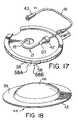
- FIG. 17shows the template patch after the intraosseous infusion and aspiration apparatus has inserted the bone portal into the bone marrow and has been disengaged, and the infusion tube has been connected to the connector tube;
- FIG. 18shows the covering for the template patch
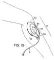
- FIG. 19shows an example of a target patch designed for use at the tibial site for intraosseous infusion.
- the apparatushas two ends: an operative end that refers to the bone penetrating end of the apparatus and the opposite end referred to as the remote end.
- the intraosseous infusion and aspiration apparatus 1serves as an introducer that introduces an object, an infusion tube 17 , to a specific position and a predetermined depth in the bone marrow 55 .
- the introduceris comprised of an outer sleeve 5 , a bone probe assembly 3 , and a coupler 7 that couples the infusion tube 17 to the outer sleeve 5 .
- the infusion tube 17is positioned in the bone marrow 55 through the action of an outer sleeve 5 , a bone probe assembly 3 that senses the location of the infusion tube 17 that is being positioned, and a coupler 7 that couples the outer sleeve 5 to the infusion tube 17 so that force exerted on the outer sleeve 5 is transferred to the infusion tube 17 .
- the automatic release mechanism of the apparatusinvolves all parts except for the infusion tube 17 .
- FIG. 1A cross-section of the intraosseous infusion and aspiration apparatus 1 is shown in its preferred embodiment in FIG. 1 .
- the apparatushas a housing assembly 2 , a plurality of balls 7 , a spring assembly 8 , a stylet 50 , stylet mount 48 , stylet base 14 and a bone probe assembly 3 .
- the housing assembly 2has an outer sleeve 5 and an inner sleeve 6 .
- the hollow outer sleeve 5is cylindrical in shape and serves as the surface to which force is applied.
- a ball race 9is formed in the interior wall of the operative end of the hollow outer sleeve 5 .
- the hollow outer sleeve 5also has a cap 16 with a projection or thread that allows it to fit snugly into the remote end of outer sleeve 5 .
- the inner sleeve 6also of cylindrical shape and hollow, slidably fits inside the hollow outer sleeve 5 .
- the inner sleeve 6has a plurality of ball holes 10 circular in shape and a plurality of elongated pin slots 11 circumferentially spaced about the operative end of the inner sleeve 6 .
- a plurality of balls 7serve as the coupler coupling the outer sleeve 5 to the infusion tube 17 .
- the balls 7couple the outer sleeve 5 , to the inner sleeve 6 which is releasably attached to the infusion tube 17 .
- the balls 7are of a diameter slightly smaller than the ball holes 10 and fit partly in the ball holes 10 of the inner sleeve 6 and partly in the ball race 9 of the hollow outer sleeve 5 coupling the hollow outer sleeve 5 with the inner sleeve 6 .
- the spring assembly 8has a helical spring 13 which is positioned inside the inner sleeve 6 , abutting a stylet base 14 .
- One side of the stylet base 14abuts a retaining lip 15 of the interior of the inner sleeve 6 proximate a remote end thereof.
- the stylet base 14has a projection that fits snugly into the remote end of the spring 13 .
- the stylet base 14couples the compression forces from spring 13 to the inner sleeve 6 .
- a stylet 50is connected to a stylet mount 48 (see FIG. 5 ) affixed to the center of the stylet base 14 .
- Stylet base 14is coupled to the inner sleeve 6 and the spring 13 .
- the force exerted onto the hollow outer sleeve 5is transferred to the inner sleeve 6 through the balls 7 coupling the two bodies 5 , 6 together and is further transferred to the spring 13 and stylet 50 through the retaining lip 15 and stylet base 14 .
- the stylet 50is rigid and is inserted into the infusion tube 17 to push the infusion tube 17 into the bone 40 .
- the infusion tube 17consists of flexible tubing 18 , and a bone portal 21 .
- the flexible tubing 18is a hollow, elongated, flexible tube connected to a tube connector 20 ( FIG. 2A ) at the remote end. Referring to FIGS. 2A and 2B , the flexible tubing 18 is connected to the bone portal 21 .
- the flexible tubing 18is attached to the bone portal 21 providing a fluid passageway from the flexible tube 18 to the bone portal 21 .
- the bone portal 21is made of a rigid material such as stainless steel and has a bore 66 which communicates with an opening at its operative end to allow the infusion of fluid into the bone marrow.
- An annular shoulder 60serves as a stop for the hollow, flexible tubing 18 that is attached to the exterior surface of the bone portal 21 .
- the end of the bone portal 21is beveled to form sharp points 62 .
- the bone portal 21 bmay be conically tapered.
- the remover 23has a slender rod threaded at its end with threads 68 dimensioned to register with the threads 22 on the interior bore of the bone portal 21 and a handle 25 at the remote end is used to remove the flexible tubing 18 and bone portal 21 from the bone marrow after the infusion is complete.
- the intraosseous infusion and aspiration apparatus 1further includes a bone probe assembly 3 that serves as a position probe allowing the location of the object, the infusion tube 17 , to be positioned relative to a reference point.
- the bone probe assembly 3comprises a bone probe ring 4 , a plurality of pins 28 , and a plurality of needles 31 .
- the bone probe ring 4comprises an annular band 26 that is dimensioned to slide into one end of the inner sleeve 6 . This annular band 26 of the bone probe ring 4 has a plurality of pin holes 27 .
- a plurality of pins 28can be put through these pin holes 27 and into the elongated pin slots 11 in the inner sleeve 6 further slidably securing the bone probe assembly 3 to the inner sleeve 6 .
- the bone probe ring 4also has a conical surface 29 (a ramp in transverse drawings) adjacent to the annular band 26 .
- a ring of needles 31protrude out from the operative end 30 of bone probe ring 4 .
- the bone probe needles 31serve as a reference for the measurement of the distance through the bone that the bone portal 21 has penetrated since the needles 31 penetrate the skin and subcutaneous layers overlying the bone, but do not penetrate the bone.
- the intraosseous infusion and aspiration apparatus 1further includes longitudinally split support sleeves 33 located in the bore of the bone probe ring 4 .
- Support sleeves 33brace the stylet 50 so that it does not buckle under the force applied to it to penetrate the bone.
- the assembled intraosseous infusion and aspiration apparatus 1is shown in its position before use with a protective covering 32 over the bone probe needles 31 .
- the intraosseous infusion and aspiration apparatus 1can be optimized for infusion of different bones such as the sternum, the proximal and distal ends of the tibia, the femur, and the clavicle. These bones have different resistances to penetration thus the amount of force needed to insert the apparatus in the bone marrow of the bones may differ. Also, since different depths of penetration of bone to reach the bone marrow may be needed for different bones, the bone penetration distance of the bone portal may need to be adjusted. In addition, the skin and subcutaneous layers overlying the different bones may differ in thickness and their resistance to penetration. The bone probe ring 4 and spring 13 may have to be adjusted to compensate for these changes in the thickness and resistance of the skin and underlying tissue. The intraosseous infusion and aspiration apparatus 1 may also be customized for pediatric patients who usually have smaller bones with lesser resistance to penetration.
- the spring force applied to the bone probe ring 4serves as a reference point to determine the depth of penetration of the bone portal 21 through the cortical bone layer 40 and bone marrow 55 .
- the magnitude of the spring force needed to force the bone probe needles 31 to penetrate the skin 56 and subcutaneous layer 57 so that it abuts the bone cortical layer 40is dependent on the bone probe needle 31 configuration, the type of tips of needles 31 , the size and the number of needles 31 , and the resistance of the skin 56 and subcutaneous layer 57 .
- a weaker spring forcemay be used for the bone probe needles 31 to penetrate the same skin and underlying tissue. Since different anatomical sites have different resistances in the skin and underlying tissues, the spring force and the bone probe needles 31 can be adjusted to obtain optimum characteristics for the penetration of the bone probe needles 31 to the cortical bone 40 .
- the ball release mechanismcomprises a plurality of balls 7 , the ball race 9 , the ball holes 10 , the spring assembly 8 and the conical surface 29 of the bone probe ring 4 and the bone probe assembly 3 itself.
- the starting position of the ball 7 before releaseis on the remote end and the ending position of the ball 7 is proximate the operative end of the conical surface 29 of the bone probe ring 4 .
- the angle of the conical surface 29 on the bone probe ring 4 , the angle of the ball contacting surface 49 of the ball race 9 and the spring forcecan be adjusted to determine the maximum bone portal penetration force available to insert the infusion tube 17 to a predetermined depth. For example, if the angle of the conical surface with the axis of the bone probe assembly ⁇ (see FIG. 7 ) is increased for a constant ball race contacting surface angle ⁇ and constant spring constant, the maximum available bone portal penetration force will decrease. If the angle ⁇ is increased as angle ⁇ and the spring constant are kept constant, the maximum available bone portal penetration force will increase. If the spring constant is increased for constant angle ⁇ and angle ⁇ , the maximum available bone portal force will increase. If this maximum bone portal force is exceeded, the apparatus 1 is released without damage. Since this force is much less than the force at which mechanical failure occurs, the apparatus will not be damaged and the patient will not be injured.
- FIG. 8shows the forces on the ball release mechanism in an initial phase where the ball is positioned at the remote end of the conical surface 29 of the bone probe ring 4 .
- forces up to the maximum forcemay be applied without premature release.
- FIG. 9shows the forces on the ball release mechanism as the balls are positioned in the operative end of the conical surface 29 of the bone probe ring 4 .
- the apparatus 1may release prematurely since there is a greater horizontal force acting on the ball 7 forcing the ball 7 onto the ramp 29 . The horizontal force tends to push the bone probe up and causes release.
- the axial displacement of the bone assembly relative to the inner sleeve 6is determined by the angle ⁇ , the angle ⁇ and the diameter of the balls 7 . Changing one of these design variables will change the axial displacement that occurs in this phase.
- Another aspect of the intraosseous infusion and aspiration apparatus 1 that can be adjustedis the size of elongated pin slots 11 (see FIG. 10-13 ) in the inner sleeve 6 proximate the operative end. These pin slots 11 determine the maximum axial displacement of the bone probe assembly 3 in relation to the inner sleeve 6 . Because the infusion tube 17 is coupled to the inner sleeve 6 , these pin slots 11 also determine the maximum penetration depth of the infusion tube 17 in relation to the bone probe needles 31 . Thus, if there is a failure in the release mechanism, this feature ensures that the bone portal 21 does not over-penetrate the bone marrow and cause injury to the patient.
- the ball race 9allows for rotational decoupling between the hollow outer sleeve 5 and the inner sleeve 6 .
- ball race sectionscould be provided in order to provide limited decoupling between the hollow outer sleeve 5 and the inner sleeve 6 .
- torquemay be used to couple the outer sleeve 5 to the inner sleeve 6 , such as a pin in outer sleeve 5 , engaging a slot of inner sleeve 6 .
- the operation of the intraosseous infusion and aspiration apparatus 1 and its release mechanismis shown in FIGS. 10 , 11 , 12 , 13 .
- the apparatus 1contains a release mechanism for disconnecting the infusion tube 17 and the bone portal 21 from the outer sleeve 5 when the bone portal 21 is at a specific depth relative to the outer surface of the cortical bone 40 thereby preventing the bone portal 21 from penetrating beyond the bone marrow 55 and out the opposite cortical layer of the bone.
- the intraosseous infusion and aspiration apparatus 1is placed on the target location perpendicular to the skin of the patient. A force is applied so that the bone probe needles 31 go through the skin 56 . A portion of the bone portal 21 also enters the subcutaneous layer 57 (see FIG. 10 ).
- the balls 7are in the ball holes 10 and ball race 9 .
- the pins 28sit at the operative end of the elongated pin slots 11 .
- the outer sleeve 5 and the inner sleeve 6move towards the operative end of the apparatus 1 .
- the infusion tube 17is coupled through the stylet 50 to the stylet base 14 which is coupled to the inner sleeve 6 which in turn is coupled to the outer sleeve 5
- the bone portal 21penetrates the bone cortical layer 40 .
- the hollow outer sleeve 5has been pushed so that the operative end of the hollow outer sleeve 5 rests on the skin of the patient.
- the balls 7have moved out of the ball race 9 , through the ball holes 10 , and down the conical surface 29 into the space between the bone probe assembly 3 and the inner sleeve 6 , uncoupling the hollow outer sleeve 5 from the inner sleeve 6 .
- Compressed spring 13exerts a force on the bone probe assembly 3 against the stylet base 14 causing the balls 7 to be pressed outwardly against the outer sleeve 5 , thereby producing a frictional force between the outer sleeve 5 , the inner sleeve 6 and the bone probe assembly 3 .
- the infusion tube 17can be connected to another tube 41 or directly to a source of drugs and fluid using the tube connector 20 on the infusion tube 17 .
- This intraosseous infusion and aspiration apparatus 1can be used in conjunction with a target/strain-relief patch 34 ( FIG. 14 ).
- the patch 34is used as a guide to ensure that the intraosseous infusion and aspiration apparatus 1 is correctly positioned in the proper location on a bone.
- a prominent anatomical feature of the bonelike a notch, a depression, or a bump is used as a reference point to determine the target location for the infusion or aspiration of the bone marrow of flat bones such as the sternum, or iliac crest and long bones such as the femur, the tibia, or the radius.
- the patch 34includes a patch base 47 which is used to locate a target zone 37 on the manubrium bone of a patient by placing the finger in peripheral notch 35 and at the same time locating the finger in the sternal notch 36 of the patient.
- a target zone 37 in the patch base 47is positioned a predetermined distance away from the peripheral notch 35 .
- the target zone 37is used to align the intraosseous infusion and aspiration apparatus 1 with a desired area of penetration of the patient.
- the patch base 47has an adhesive underside with a liner 58 that can be peeled to removably fasten the patch base 47 to the skin 56 of the patient.
- Liner 58may be split such that it has two pieces that can be removed independent of one another. See, for example, FIG. 17 which shows liner 58 made up of a first piece 58 A and second piece 58 B.
- a fastening material 38is present around the periphery of the patch base 47 so that a cover 44 may be placed on it and engage the fastening material 45 ( FIG. 18 ).
- the patch 34also has a tube clamp 39 outside the fastening material 45 on an extension of the patch base 47 .
- the infusion tube 17may be attached by the tube clamp 39 to the patch 34 and then connected to an intravenous tube through its tube connector 20 .
- a connector tube 41 with a connector 42 and a connector 43is attached to the tube clamp 39 .
- Connector tube 41is attached to the tube connector 20 on the infusion tube 17 with connector 42 , and connector 43 is used to attach connector tube 41 to a source of fluids.
- the tube clamp 39 or the connector tube 41decrease the strain on the bone portal 21 by creating the slack in the tube and also prevent the accidental dislodgment of the infusion tube 17 and the bone portal 21 by either clamping the infusion tube 17 or the connector tube 41 to the patch base 47 .
- the intraosseous infusion and aspiration apparatus 1is placed perpendicular to the patch 34 in the target zone 37 .
- the infusion tube 17is connected to the connector tube 41 with the tube connector 20 and connector 42 as shown in FIG. 17 .
- Connector 43 of the connector tube 41can be connected to a source of intravenous drugs or fluid.
- FIG. 18shows a preferred embodiment of the cover 44 which has a dome 46 of transparent material with fastening material 45 around its periphery.
- the dome 46can be placed on the patch base 47 and the fastening material 38 of the patch base 47 can engage with the fastening material 45 of the cover 44 to protect the site of infusion.
- the fastening materialscan be hook and loop which allows the dome to be removed and reattached.
- the intraosseous infusion and aspiration apparatus 1can be used alone if a patch 34 is not available, or in conjunction with the patch 34 .
- the patch 34may also be used with other intraosseous infusion and aspiration apparatus.
- a patch 34is used in conjunction with the intraosseous infusion apparatus 1 , the top half of the backing of the patch 34 is first removed to expose the adhesive lining on the underside.
- An appropriate anatomical marker on the appropriate boneis located, for example the sternal notch 36 in the manubrium bone of the patient.
- An index fingeris placed on the anatomical marker perpendicular to the surface of the bone and the peripheral notch 35 on the patch 34 is arranged around the finger in the proper orientation.
- peripheral notch 35 and the target zone 37are over the patient's midline on the chest.
- the top half of the patch 34is pressed onto the skin and the rest of the backing is removed to expose the rest of the adhesive lining that secures the patch 34 to the skin of the patient.
- the bone probe needles 31 protective covering 32is removed, and the bone probe needles 31 are placed on the target zone 37 with the axis of the apparatus 1 perpendicular to the skin of the patient.
- the hollow outer sleeve 5is pushed into the target zone 37 until the release of the hollow outer sleeve 5 from the inner sleeve 6 is heard and felt.
- the hollow outer sleeve 5is pulled straight back.
- the support sleeves 33fall out leaving the infusion tube 17 with bone portal 21 embedded in the patient.
- a syringeis attached to the infusion tube 17 to withdraw marrow to verify that the infusion tube 17 is at the correct depth in the bone.
- the bone probe needles 31 protective covering 32is put back on the apparatus 1 for safety reasons.
- the infusion tube 17is connected to a connector tube 41 attached at the patch 34 through the tube connector 20 to provide slack in the tubing and less strain on the infusion site.
- the connector tube 41is connected to a supply of intravenous drugs or fluid.
- the protective cover 44is placed on the patch 34 so as to engage the covering fastening material 45 with the patch fastening material 38 , protecting the infusion tube 17 from dislodgement.
- the infusion tube 17may be removed by inserting a remover 23 into the infusion tube 17 and turning it clockwise to engage the threads in the bone portal 21 until the remover stops turning. The remover is then pulled straight out removing the infusion tube 17 from the patient.
- a tibial target patch 51 designed for use at the tibial site for intraosseous infusionis shown. This is a site commonly used in children, and occasionally used in adult patients.
- the tibial site target patch 51has an alignment feature 52 that is aligned with the tibial tuberosity at the proximal end of the tibia.
- the tibial target patch 51has a marking 53 on it for aligning with the ridge of bone that can be felt along the axis of the tibia.
- the tibial target patch 51has an adhesive backing with a liner that is removed to place the patch on the skin.
- the tibial target patch 51has a tibial target zone 54 that is used as a target for placing any intraosseous needle. This invention removes the need for judging the distances from the anatomical landmarks.
- the patchcould also have an instrument guide (not shown) that guides the needle into the bone at the recommended angle of 45 degrees.
- the patchcould also have loop fasteners for attaching a protective dome designed for placement at this site.
- the patchcould also have a connector tubing bonded to the patch to remove stress and strain from the infusion tube or needle.
- a similar target patchcan easily be envisioned for use at other target sites, for example the distal end of the tibia, near the ankle; the distal end of the femur near the knee; the iliac crest site; or the distal end of the radius (lower arm).
Landscapes
- Health & Medical Sciences (AREA)
- Life Sciences & Earth Sciences (AREA)
- Public Health (AREA)
- Veterinary Medicine (AREA)
- Biomedical Technology (AREA)
- Heart & Thoracic Surgery (AREA)
- Hematology (AREA)
- Engineering & Computer Science (AREA)
- Animal Behavior & Ethology (AREA)
- General Health & Medical Sciences (AREA)
- Vascular Medicine (AREA)
- Anesthesiology (AREA)
- Immunology (AREA)
- Orthopedic Medicine & Surgery (AREA)
- Rheumatology (AREA)
- Pathology (AREA)
- Medical Informatics (AREA)
- Molecular Biology (AREA)
- Surgery (AREA)
- Dermatology (AREA)
- Infusion, Injection, And Reservoir Apparatuses (AREA)
- Media Introduction/Drainage Providing Device (AREA)
Abstract
Description
- Bone probe needles: Ten 1.27 mm hypodermic needles equi-spaced around the bone probe.
- angle φ=15 degrees
- angle θ=60 degrees
- Ball radius=3.16 mm
- Maximum force on spring=9.1 kg
- Activation distance of bone portal relative to end of bone probe needles=8.87 mm
- Bone probe needles: Ten 1.27 mm hypodermic needles equi-spaced around the bone probe.
Claims (24)
Priority Applications (3)
| Application Number | Priority Date | Filing Date | Title |
|---|---|---|---|
| US10/860,046US7347840B2 (en) | 2000-03-02 | 2004-06-04 | Patch for locating a target zone for penetration |
| US12/012,794US8486027B2 (en) | 1998-05-15 | 2008-02-05 | Bone-penetrating member for intraosseous infusion and aspiration devices |
| US13/711,246US20130102924A1 (en) | 1997-05-16 | 2012-12-11 | Apparatus for introducing intraosseous portals |
Applications Claiming Priority (2)
| Application Number | Priority Date | Filing Date | Title |
|---|---|---|---|
| US09/423,855US6761726B1 (en) | 1998-05-15 | 1998-05-15 | Method and apparatus for the intraosseous introduction of a device such as an infusion tube |
| US10/860,046US7347840B2 (en) | 2000-03-02 | 2004-06-04 | Patch for locating a target zone for penetration |
Related Parent Applications (2)
| Application Number | Title | Priority Date | Filing Date |
|---|---|---|---|
| US09/423,855DivisionUS6761726B1 (en) | 1997-05-16 | 1998-05-15 | Method and apparatus for the intraosseous introduction of a device such as an infusion tube |
| PCT/CA1998/000492DivisionWO1998052638A2 (en) | 1997-05-16 | 1998-05-15 | Method and apparatus for the intraosseous introduction of a device such as an infusion tube |
Related Child Applications (1)
| Application Number | Title | Priority Date | Filing Date |
|---|---|---|---|
| US12/012,794ContinuationUS8486027B2 (en) | 1997-05-16 | 2008-02-05 | Bone-penetrating member for intraosseous infusion and aspiration devices |
Publications (2)
| Publication Number | Publication Date |
|---|---|
| US20040220497A1 US20040220497A1 (en) | 2004-11-04 |
| US7347840B2true US7347840B2 (en) | 2008-03-25 |
Family
ID=33309595
Family Applications (3)
| Application Number | Title | Priority Date | Filing Date |
|---|---|---|---|
| US10/860,046Expired - Fee RelatedUS7347840B2 (en) | 1997-05-16 | 2004-06-04 | Patch for locating a target zone for penetration |
| US12/012,794Expired - Fee RelatedUS8486027B2 (en) | 1997-05-16 | 2008-02-05 | Bone-penetrating member for intraosseous infusion and aspiration devices |
| US13/711,246AbandonedUS20130102924A1 (en) | 1997-05-16 | 2012-12-11 | Apparatus for introducing intraosseous portals |
Family Applications After (2)
| Application Number | Title | Priority Date | Filing Date |
|---|---|---|---|
| US12/012,794Expired - Fee RelatedUS8486027B2 (en) | 1997-05-16 | 2008-02-05 | Bone-penetrating member for intraosseous infusion and aspiration devices |
| US13/711,246AbandonedUS20130102924A1 (en) | 1997-05-16 | 2012-12-11 | Apparatus for introducing intraosseous portals |
Country Status (1)
| Country | Link |
|---|---|
| US (3) | US7347840B2 (en) |
Cited By (31)
| Publication number | Priority date | Publication date | Assignee | Title |
|---|---|---|---|---|
| US20060015066A1 (en)* | 2004-05-17 | 2006-01-19 | Turieo Melanie J | Intraosseous infusion device |
| US20100286607A1 (en)* | 2009-05-05 | 2010-11-11 | Saltzstein William E | Patient status sensor |
| US20100298831A1 (en)* | 2007-12-07 | 2010-11-25 | Pyng Medical Corp. | Apparatus for introducing portals in bone having movable bone probe |
| WO2015050788A1 (en) | 2013-09-26 | 2015-04-09 | Krimsky William Sanford | Assist device for medical procedures |
| EP3167828A1 (en) | 2015-11-15 | 2017-05-17 | Waismed Ltd | Apparatus for use in conjunction with an intraosseous device |
| US20180008792A1 (en)* | 2016-07-08 | 2018-01-11 | Wolf Technical Services, Inc. | Cricotherotomy apparatus and method |
| US9907693B2 (en) | 2007-11-14 | 2018-03-06 | Myoscience, Inc. | Pain management using cryogenic remodeling |
| USD839422S1 (en)* | 2016-07-08 | 2019-01-29 | Gerresheimer Regensburg Gmbh | Needle protection for a syringe device |
| US11134998B2 (en) | 2017-11-15 | 2021-10-05 | Pacira Cryotech, Inc. | Integrated cold therapy and electrical stimulation systems for locating and treating nerves and associated methods |
| US11134999B2 (en) | 2013-03-15 | 2021-10-05 | Pacira Cryotech, Inc. | Methods and systems for treatment of occipital neuralgia |
| US11253393B2 (en) | 2013-03-15 | 2022-02-22 | Pacira Cryotech, Inc. | Methods, systems, and devices for treating neuromas, fibromas, nerve entrapment, and/or pain associated therewith |
| US11311327B2 (en) | 2016-05-13 | 2022-04-26 | Pacira Cryotech, Inc. | Methods and systems for locating and treating nerves with cold therapy |
| US11357515B2 (en) | 2017-09-09 | 2022-06-14 | June Access Ip, Llc | Intraosseous device having retractable motor/stylet assembly and automatic stylet point cover upon retraction operation |
| US11484339B2 (en) | 2017-09-09 | 2022-11-01 | June Access, IP LLC | Passive safety intraosseous device |
| US11517349B2 (en) | 2019-09-27 | 2022-12-06 | Bard Access Systems, Inc. | Autovance feature of an intraosseous device |
| US11633214B2 (en) | 2019-09-27 | 2023-04-25 | Bard Access Systems, Inc. | Various operating mechanisms for intraosseous access medical devices and methods thereof |
| US11642241B2 (en) | 2013-03-15 | 2023-05-09 | Pacira Cryotech, Inc. | Cryogenic enhancement of joint function, alleviation of joint stiffness and/or alleviation of pain associated with osteoarthritis |
| US11759235B2 (en) | 2019-09-27 | 2023-09-19 | Bard Access Systems, Inc. | Constant-torque intraosseous access devices and methods thereof |
| US11771462B2 (en)* | 2011-07-11 | 2023-10-03 | Teleflex Life Sciences Limited | Sternal locators and associated systems and methods |
| US11883071B2 (en) | 2016-10-27 | 2024-01-30 | C. R. Bard, Inc. | Intraosseous access device |
| US11896264B2 (en) | 2020-04-21 | 2024-02-13 | Bard Access Systems, Inc. | Reusable push-activated intraosseous access device |
| US11925361B2 (en) | 2021-02-08 | 2024-03-12 | Bard Access Systems, Inc. | Intraosseous modular power |
| US11998237B2 (en) | 2020-06-03 | 2024-06-04 | Bard Access Systems, Inc. | Intraosseous device including a sensing obturator |
| US12082843B2 (en) | 2019-09-27 | 2024-09-10 | Bard Access Systems, Inc. | Step needle for intraosseous access device |
| US12167869B2 (en) | 2020-02-28 | 2024-12-17 | Bard Access Systems, Inc. | Flexible intraosseous obturator |
| US12188328B2 (en) | 2023-05-15 | 2025-01-07 | Saudi Arabian Oil Company | Wellbore back pressure valve with pressure gauge |
| US12226123B2 (en) | 2020-07-17 | 2025-02-18 | Bard Access Systems, Inc. | Safety mechanism |
| US12234701B2 (en) | 2022-09-12 | 2025-02-25 | Saudi Arabian Oil Company | Tubing hangers and related methods of isolating a tubing |
| US12274469B2 (en) | 2020-08-25 | 2025-04-15 | Bard Access Systems, Inc. | Angled intraosseous access system |
| US12402911B2 (en) | 2020-09-09 | 2025-09-02 | Bard Access Systems, Inc. | Aspiration apparatus for intraosseous access system |
| US12442257B2 (en) | 2023-05-23 | 2025-10-14 | Saudi Arabian Oil Company | Completing and working over a wellbore |
Families Citing this family (71)
| Publication number | Priority date | Publication date | Assignee | Title |
|---|---|---|---|---|
| US8641715B2 (en) | 2002-05-31 | 2014-02-04 | Vidacare Corporation | Manual intraosseous device |
| US9451968B2 (en) | 2002-05-31 | 2016-09-27 | Vidacare LLC | Powered drivers, intraosseous devices and methods to access bone marrow |
| US9072543B2 (en) | 2002-05-31 | 2015-07-07 | Vidacare LLC | Vascular access kits and methods |
| US9314228B2 (en) | 2002-05-31 | 2016-04-19 | Vidacare LLC | Apparatus and method for accessing the bone marrow |
| US11337728B2 (en) | 2002-05-31 | 2022-05-24 | Teleflex Life Sciences Limited | Powered drivers, intraosseous devices and methods to access bone marrow |
| US11298202B2 (en) | 2002-05-31 | 2022-04-12 | Teleflex Life Sciences Limited | Biopsy devices and related methods |
| US20070049945A1 (en) | 2002-05-31 | 2007-03-01 | Miller Larry J | Apparatus and methods to install, support and/or monitor performance of intraosseous devices |
| US8690791B2 (en) | 2002-05-31 | 2014-04-08 | Vidacare Corporation | Apparatus and method to access the bone marrow |
| US8668698B2 (en) | 2002-05-31 | 2014-03-11 | Vidacare Corporation | Assembly for coupling powered driver with intraosseous device |
| US7951089B2 (en) | 2002-05-31 | 2011-05-31 | Vidacare Corporation | Apparatus and methods to harvest bone and bone marrow |
| US7850620B2 (en) | 2002-05-31 | 2010-12-14 | Vidacare Corporation | Biopsy devices and related methods |
| US10973545B2 (en) | 2002-05-31 | 2021-04-13 | Teleflex Life Sciences Limited | Powered drivers, intraosseous devices and methods to access bone marrow |
| US8142365B2 (en) | 2002-05-31 | 2012-03-27 | Vidacare Corporation | Apparatus and method for accessing the bone marrow of the sternum |
| US7811260B2 (en) | 2002-05-31 | 2010-10-12 | Vidacare Corporation | Apparatus and method to inject fluids into bone marrow and other target sites |
| EP2039298B1 (en) | 2002-05-31 | 2017-10-25 | Vidacare LLC | Apparatus to access bone marrow |
| US10973532B2 (en) | 2002-05-31 | 2021-04-13 | Teleflex Life Sciences Limited | Powered drivers, intraosseous devices and methods to access bone marrow |
| EP1542587B1 (en) | 2002-08-24 | 2011-04-27 | St. Jude Medical, Atrial Fibrillation Division, Inc. | Method and apparatus for locating the fossa ovalis and performing transseptal puncture |
| EP1475113A1 (en)* | 2003-05-08 | 2004-11-10 | Novo Nordisk A/S | External needle inserter |
| JP4509100B2 (en)* | 2003-05-08 | 2010-07-21 | ノボ・ノルデイスク・エー/エス | Infusion device attachable to skin with removable needle insertion actuation |
| ATE392223T1 (en)* | 2003-05-08 | 2008-05-15 | Novo Nordisk As | INTERNAL NEEDLE INTRODUCER |
| US9504477B2 (en) | 2003-05-30 | 2016-11-29 | Vidacare LLC | Powered driver |
| EP1502613A1 (en) | 2003-08-01 | 2005-02-02 | Novo Nordisk A/S | Needle device with retraction means |
| CN101536926B (en) | 2004-01-26 | 2012-07-18 | 维达保健公司 | Manual interosseous device |
| US7815642B2 (en) | 2004-01-26 | 2010-10-19 | Vidacare Corporation | Impact-driven intraosseous needle |
| CN100586495C (en) | 2004-03-30 | 2010-02-03 | 诺和诺德公司 | Actuator system comprising lever mechanism |
| DE102004028429B3 (en)* | 2004-06-03 | 2005-11-03 | Karl Storz Gmbh & Co. Kg | Device for punching out tissue areas on bones |
| US8998848B2 (en) | 2004-11-12 | 2015-04-07 | Vidacare LLC | Intraosseous device and methods for accessing bone marrow in the sternum and other target areas |
| US8167841B2 (en) | 2005-01-24 | 2012-05-01 | Novo Nordisk A/S | Transcutaneous device assembly |
| JP4904293B2 (en)* | 2005-03-03 | 2012-03-28 | セント・ジュード・メディカル・エイトリアル・フィブリレーション・ディヴィジョン・インコーポレーテッド | Method and apparatus for determining the location of the foveal fossa, creating a virtual foveal fossa and performing a transseptal puncture |
| US7713266B2 (en) | 2005-05-20 | 2010-05-11 | Myoscience, Inc. | Subdermal cryogenic remodeling of muscles, nerves, connective tissue, and/or adipose tissue (fat) |
| US7850683B2 (en) | 2005-05-20 | 2010-12-14 | Myoscience, Inc. | Subdermal cryogenic remodeling of muscles, nerves, connective tissue, and/or adipose tissue (fat) |
| US10034674B2 (en)* | 2006-02-02 | 2018-07-31 | Steven C Chudik | Universal anterior cruciate ligament repair and reconstruction system |
| EP1997233B1 (en) | 2006-03-13 | 2014-03-05 | Novo Nordisk A/S | Secure pairing of electronic devices using dual means of communication |
| EP2032188A1 (en) | 2006-06-06 | 2009-03-11 | Novo Nordisk A/S | Assembly comprising skin-mountable device and packaging therefore |
| EP3189787B1 (en) | 2006-09-12 | 2019-01-09 | Teleflex Medical Devices S.à.r.l. | Medical procedures trays and related methods |
| EP2073728B1 (en) | 2006-09-12 | 2018-11-07 | Teleflex Medical Devices S.à.r.l. | Biopsy device |
| EP2068743B1 (en) | 2006-09-12 | 2017-03-15 | Vidacare LLC | Medical procedures trays, kits and related methods |
| US8944069B2 (en) | 2006-09-12 | 2015-02-03 | Vidacare Corporation | Assemblies for coupling intraosseous (IO) devices to powered drivers |
| US7468048B2 (en) | 2006-10-06 | 2008-12-23 | National Jewish Health | Joint aspirate facilitating device |
| US8974410B2 (en) | 2006-10-30 | 2015-03-10 | Vidacare LLC | Apparatus and methods to communicate fluids and/or support intraosseous devices |
| US9254162B2 (en) | 2006-12-21 | 2016-02-09 | Myoscience, Inc. | Dermal and transdermal cryogenic microprobe systems |
| US8409185B2 (en) | 2007-02-16 | 2013-04-02 | Myoscience, Inc. | Replaceable and/or easily removable needle systems for dermal and transdermal cryogenic remodeling |
| CN101888859B (en) | 2007-10-31 | 2014-09-17 | 诺沃-诺迪斯克有限公司 | Non-porous material as sterilization barrier |
| WO2009148969A1 (en) | 2008-06-02 | 2009-12-10 | Sta-Med, Llc | Needle cover assembly for a syringe |
| JP5642087B2 (en) | 2008-12-22 | 2014-12-17 | ミオサイエンス インコーポレーティッド | Integrated cryosurgery system with refrigerant and power supply |
| USD633199S1 (en)* | 2009-10-05 | 2011-02-22 | Pyng Medical Corp. | Insertion tool for bone portals |
| WO2011097311A2 (en) | 2010-02-02 | 2011-08-11 | Vidacare Corporation | Intraosseous-needle stabilizer and methods |
| US8162882B2 (en) | 2010-06-23 | 2012-04-24 | Sta-Med, Llc | Automatic-locking safety needle covers and methods of use and manufacture |
| CN103561673A (en)* | 2010-12-13 | 2014-02-05 | 肌肉科技股份有限公司 | Method for reducing hyperdynamic facial wrinkles |
| IL212263A (en)* | 2011-04-11 | 2014-01-30 | Alexander Kalnitskiy | Intraosseous device for inserting a cannula into a bone |
| WO2012166746A1 (en) | 2011-05-31 | 2012-12-06 | Sta-Med, Llc | Blood collection safety devices and methods of use and manufacture |
| CN104379207A (en) | 2011-12-28 | 2015-02-25 | 克里尔医疗有限公司 | System and method for blood filtering and/or treatment |
| WO2013106860A1 (en) | 2012-01-13 | 2013-07-18 | Myoscience, Inc. | Cryogenic probe filtration system |
| CN104159534B (en) | 2012-01-13 | 2017-02-22 | 肌肉科技股份有限公司 | Skin protection for subdermal cryogenic remodeling for cosmetic and other treatments |
| EP2802279B1 (en) | 2012-01-13 | 2017-08-16 | Myoscience, Inc. | Cryogenic needle with freeze zone regulation |
| US9017318B2 (en) | 2012-01-20 | 2015-04-28 | Myoscience, Inc. | Cryogenic probe system and method |
| US9271752B2 (en)* | 2013-03-13 | 2016-03-01 | Swan Valley Medical Incorporated | Method and apparatus for placing a cannula in a bladder |
| WO2014146126A1 (en) | 2013-03-15 | 2014-09-18 | Myoscience, Inc. | Cryogenic blunt dissection methods and devices |
| JP2016530050A (en)* | 2013-09-11 | 2016-09-29 | デバイオテック・ソシエテ・アノニム | Needle insertion device |
| US10524833B2 (en)* | 2013-11-04 | 2020-01-07 | Fnapen Llc | Device and methods for precise control of medical procedures |
| US10130409B2 (en) | 2013-11-05 | 2018-11-20 | Myoscience, Inc. | Secure cryosurgical treatment system |
| JP6835731B2 (en) | 2014-11-13 | 2021-02-24 | パヴメド・インコーポレイテッドPAVMed Inc. | Intraosseous infusion port and usage |
| IL243347A0 (en) | 2015-12-24 | 2016-04-21 | Waismed Ltd | Automatic device and kit for inserting a cannula to a predetermined depth within a bone, irrespective of the thickness of the tissue above the bone |
| WO2018075694A1 (en) | 2016-10-18 | 2018-04-26 | Piper Access, Llc | Intraosseous access devices, systems, and methods |
| US10265481B2 (en)* | 2016-11-02 | 2019-04-23 | Abul Bashar Mohammad Anwarul Islam | Intramarrow injection/infusion and aspiration needle and method |
| JP7169982B2 (en) | 2017-03-07 | 2022-11-11 | パイパー・アクセス、エルエルシー | Safety shields for elongated instruments and related systems and methods |
| CA3050963A1 (en) | 2017-03-10 | 2018-09-13 | Piper Access, Llc. | Securement devices, systems, and methods |
| ES2953372T3 (en) | 2018-02-20 | 2023-11-10 | Piper Access Llc | Drilling devices and related methods |
| WO2020185961A1 (en)* | 2019-03-11 | 2020-09-17 | MFr Technologies, Inc. | Tissue coring device |
| WO2020261070A1 (en)* | 2019-06-22 | 2020-12-30 | Teleflex Medical Devices S.A.R.L. | Bone-penetrating intraosseous access device |
| US12076045B2 (en) | 2021-03-03 | 2024-09-03 | Arthrex, Inc. | Surgical systems for percutaneously inserting surgical devices |
Citations (22)
| Publication number | Priority date | Publication date | Assignee | Title |
|---|---|---|---|---|
| US2448708A (en) | 1944-12-05 | 1948-09-07 | Carl G Geissler | Medical divider |
| US3791386A (en) | 1971-09-27 | 1974-02-12 | Mc Donald Medical Lab Instr Co | Tracheotomy method and means |
| US3815605A (en) | 1971-05-19 | 1974-06-11 | Philips Corp | Device and holder therefor for inserting a hollow coupling member into bone marrow |
| US3991765A (en)* | 1975-04-09 | 1976-11-16 | Howard Cohen | Cricothyrotomy apparatus |
| US4646731A (en)* | 1985-05-20 | 1987-03-03 | Brower Arthur B | Self adhesive suture and bandage |
| US4659329A (en)* | 1984-07-27 | 1987-04-21 | The Kendall Company | Liquid drainage system |
| US4711636A (en)* | 1985-11-08 | 1987-12-08 | Bierman Steven F | Catheterization system |
| US4874380A (en) | 1988-01-07 | 1989-10-17 | E. R. Squibb And Sons, Inc. | Catheter retaining device |
| US4969870A (en) | 1989-06-07 | 1990-11-13 | The Regents Of The University Of California | Method and apparatus for intraosseous infusions |
| US4985019A (en) | 1988-03-11 | 1991-01-15 | Michelson Gary K | X-ray marker |
| US5116324A (en)* | 1991-07-15 | 1992-05-26 | Brierley Carol L | Protector for IV site |
| US5364361A (en) | 1993-10-26 | 1994-11-15 | Battenfield Harold L | Knee bursa draining template and cannulated needle for use therewith |
| US5520650A (en) | 1994-08-25 | 1996-05-28 | Zadini; Filiberto | Self-arresting overpenetration-proof cannula device for body cavities |
| US5591188A (en) | 1994-04-12 | 1997-01-07 | Wais-Med Lmt, A Subsidiary Company Of Teic Technion Enterpreneurial Incubator Ltd. | Surgical instrument for impact insertion of an intraosseous trocar-needle |
| US5817052A (en) | 1995-12-26 | 1998-10-06 | Pyng Medical Corp. | Apparatus for intraosseous infusion or aspiration |
| CA2205623A1 (en) | 1997-05-16 | 1998-11-16 | Pyng Medical Corp. | Method and apparatus for intraosseous infusion and aspiration using an automatic release mechanism |
| US5858005A (en)* | 1997-08-27 | 1999-01-12 | Science Incorporated | Subcutaneous infusion set with dynamic needle |
| US5868711A (en)* | 1991-04-29 | 1999-02-09 | Board Of Regents, The University Of Texas System | Implantable intraosseous device for rapid vascular access |
| US5891085A (en) | 1995-01-09 | 1999-04-06 | Medi-Ject Corporation | Nozzle assembly with lost motion connection for medical injector assembly |
| US6017348A (en) | 1995-03-07 | 2000-01-25 | Innovasive Devices, Inc. | Apparatus and methods for articular cartilage defect repair |
| US6248110B1 (en) | 1994-01-26 | 2001-06-19 | Kyphon, Inc. | Systems and methods for treating fractured or diseased bone using expandable bodies |
| US6761726B1 (en) | 1998-05-15 | 2004-07-13 | Pyng Medical Corp. | Method and apparatus for the intraosseous introduction of a device such as an infusion tube |
Family Cites Families (2)
| Publication number | Priority date | Publication date | Assignee | Title |
|---|---|---|---|---|
| US2426535A (en)* | 1944-10-21 | 1947-08-26 | Turkel Henry | Infusion and biopsy needle |
| US2705949A (en)* | 1953-08-25 | 1955-04-12 | Silverman Irving | Biopsy needle |
- 2004
- 2004-06-04USUS10/860,046patent/US7347840B2/ennot_activeExpired - Fee Related
- 2008
- 2008-02-05USUS12/012,794patent/US8486027B2/ennot_activeExpired - Fee Related
- 2012
- 2012-12-11USUS13/711,246patent/US20130102924A1/ennot_activeAbandoned
Patent Citations (22)
| Publication number | Priority date | Publication date | Assignee | Title |
|---|---|---|---|---|
| US2448708A (en) | 1944-12-05 | 1948-09-07 | Carl G Geissler | Medical divider |
| US3815605A (en) | 1971-05-19 | 1974-06-11 | Philips Corp | Device and holder therefor for inserting a hollow coupling member into bone marrow |
| US3791386A (en) | 1971-09-27 | 1974-02-12 | Mc Donald Medical Lab Instr Co | Tracheotomy method and means |
| US3991765A (en)* | 1975-04-09 | 1976-11-16 | Howard Cohen | Cricothyrotomy apparatus |
| US4659329A (en)* | 1984-07-27 | 1987-04-21 | The Kendall Company | Liquid drainage system |
| US4646731A (en)* | 1985-05-20 | 1987-03-03 | Brower Arthur B | Self adhesive suture and bandage |
| US4711636A (en)* | 1985-11-08 | 1987-12-08 | Bierman Steven F | Catheterization system |
| US4874380A (en) | 1988-01-07 | 1989-10-17 | E. R. Squibb And Sons, Inc. | Catheter retaining device |
| US4985019A (en) | 1988-03-11 | 1991-01-15 | Michelson Gary K | X-ray marker |
| US4969870A (en) | 1989-06-07 | 1990-11-13 | The Regents Of The University Of California | Method and apparatus for intraosseous infusions |
| US5868711A (en)* | 1991-04-29 | 1999-02-09 | Board Of Regents, The University Of Texas System | Implantable intraosseous device for rapid vascular access |
| US5116324A (en)* | 1991-07-15 | 1992-05-26 | Brierley Carol L | Protector for IV site |
| US5364361A (en) | 1993-10-26 | 1994-11-15 | Battenfield Harold L | Knee bursa draining template and cannulated needle for use therewith |
| US6248110B1 (en) | 1994-01-26 | 2001-06-19 | Kyphon, Inc. | Systems and methods for treating fractured or diseased bone using expandable bodies |
| US5591188A (en) | 1994-04-12 | 1997-01-07 | Wais-Med Lmt, A Subsidiary Company Of Teic Technion Enterpreneurial Incubator Ltd. | Surgical instrument for impact insertion of an intraosseous trocar-needle |
| US5520650A (en) | 1994-08-25 | 1996-05-28 | Zadini; Filiberto | Self-arresting overpenetration-proof cannula device for body cavities |
| US5891085A (en) | 1995-01-09 | 1999-04-06 | Medi-Ject Corporation | Nozzle assembly with lost motion connection for medical injector assembly |
| US6017348A (en) | 1995-03-07 | 2000-01-25 | Innovasive Devices, Inc. | Apparatus and methods for articular cartilage defect repair |
| US5817052A (en) | 1995-12-26 | 1998-10-06 | Pyng Medical Corp. | Apparatus for intraosseous infusion or aspiration |
| CA2205623A1 (en) | 1997-05-16 | 1998-11-16 | Pyng Medical Corp. | Method and apparatus for intraosseous infusion and aspiration using an automatic release mechanism |
| US5858005A (en)* | 1997-08-27 | 1999-01-12 | Science Incorporated | Subcutaneous infusion set with dynamic needle |
| US6761726B1 (en) | 1998-05-15 | 2004-07-13 | Pyng Medical Corp. | Method and apparatus for the intraosseous introduction of a device such as an infusion tube |
Cited By (54)
| Publication number | Priority date | Publication date | Assignee | Title |
|---|---|---|---|---|
| US20060015066A1 (en)* | 2004-05-17 | 2006-01-19 | Turieo Melanie J | Intraosseous infusion device |
| US10864112B2 (en) | 2007-11-14 | 2020-12-15 | Pacira Cryotech, Inc. | Pain management using cryogenic remodeling |
| US10869779B2 (en) | 2007-11-14 | 2020-12-22 | Pacira Cryotech, Inc. | Pain management using cryogenic remodeling |
| US12178746B2 (en) | 2007-11-14 | 2024-12-31 | Pacira Cryotech, Inc. | Pain management using cryogenic remodeling |
| US9907693B2 (en) | 2007-11-14 | 2018-03-06 | Myoscience, Inc. | Pain management using cryogenic remodeling |
| US11672694B2 (en) | 2007-11-14 | 2023-06-13 | Pacira Cryotech, Inc. | Pain management using cryogenic remodeling |
| US20140039400A1 (en)* | 2007-12-07 | 2014-02-06 | Pyng Medical Corp. | Apparatus and methods for introducing portals in bone |
| US8562615B2 (en)* | 2007-12-07 | 2013-10-22 | Pyng Medical Corp. | Apparatus for introducing portals in bone having transversely movable bone probe |
| US8388623B2 (en)* | 2007-12-07 | 2013-03-05 | Pyng Medical Corp. | Apparatus for introducing portals in bone having movable bone probe |
| US8663231B2 (en) | 2007-12-07 | 2014-03-04 | Pyng Medical Corp. | Apparatus and methods for introducing portals in bone |
| US8333769B2 (en) | 2007-12-07 | 2012-12-18 | Pyng Medical Corp. | Apparatus and methods for introducing portals in bone |
| US9480483B2 (en)* | 2007-12-07 | 2016-11-01 | Pyng Medical Corp. | Apparatus and methods for introducing portals in bone |
| US9724106B2 (en) | 2007-12-07 | 2017-08-08 | Pyng Medical Corp. | Apparatus and methods for introducing portals in bone |
| US20100312246A1 (en)* | 2007-12-07 | 2010-12-09 | Pyng Medical Corp. | Apparatus and methods for introducing portals in bone |
| US20100298831A1 (en)* | 2007-12-07 | 2010-11-25 | Pyng Medical Corp. | Apparatus for introducing portals in bone having movable bone probe |
| US10722247B2 (en)* | 2007-12-07 | 2020-07-28 | Pyng Medical Corp. | Apparatus and methods for introducing portals in bone |
| US8273053B2 (en) | 2009-05-05 | 2012-09-25 | Pyng Medical Corp. | Patient status sensor |
| US20100286607A1 (en)* | 2009-05-05 | 2010-11-11 | Saltzstein William E | Patient status sensor |
| US11771462B2 (en)* | 2011-07-11 | 2023-10-03 | Teleflex Life Sciences Limited | Sternal locators and associated systems and methods |
| US11253393B2 (en) | 2013-03-15 | 2022-02-22 | Pacira Cryotech, Inc. | Methods, systems, and devices for treating neuromas, fibromas, nerve entrapment, and/or pain associated therewith |
| US11134999B2 (en) | 2013-03-15 | 2021-10-05 | Pacira Cryotech, Inc. | Methods and systems for treatment of occipital neuralgia |
| US11865038B2 (en) | 2013-03-15 | 2024-01-09 | Pacira Cryotech, Inc. | Methods, systems, and devices for treating nerve spasticity |
| US11642241B2 (en) | 2013-03-15 | 2023-05-09 | Pacira Cryotech, Inc. | Cryogenic enhancement of joint function, alleviation of joint stiffness and/or alleviation of pain associated with osteoarthritis |
| US10758695B2 (en) | 2013-09-26 | 2020-09-01 | Innovital Llc | Assist device for medical procedures |
| WO2015050788A1 (en) | 2013-09-26 | 2015-04-09 | Krimsky William Sanford | Assist device for medical procedures |
| EP3167828A1 (en) | 2015-11-15 | 2017-05-17 | Waismed Ltd | Apparatus for use in conjunction with an intraosseous device |
| US11311327B2 (en) | 2016-05-13 | 2022-04-26 | Pacira Cryotech, Inc. | Methods and systems for locating and treating nerves with cold therapy |
| US12076069B2 (en) | 2016-05-13 | 2024-09-03 | Pacira Cryotech, Inc. | Methods and systems for locating and treating nerves with cold therapy |
| US10806881B2 (en)* | 2016-07-08 | 2020-10-20 | Wolf Technical Services, Inc. | Cricotherotomy apparatus and method |
| USD839422S1 (en)* | 2016-07-08 | 2019-01-29 | Gerresheimer Regensburg Gmbh | Needle protection for a syringe device |
| US20180008792A1 (en)* | 2016-07-08 | 2018-01-11 | Wolf Technical Services, Inc. | Cricotherotomy apparatus and method |
| US11883071B2 (en) | 2016-10-27 | 2024-01-30 | C. R. Bard, Inc. | Intraosseous access device |
| US11357515B2 (en) | 2017-09-09 | 2022-06-14 | June Access Ip, Llc | Intraosseous device having retractable motor/stylet assembly and automatic stylet point cover upon retraction operation |
| US11484339B2 (en) | 2017-09-09 | 2022-11-01 | June Access, IP LLC | Passive safety intraosseous device |
| US12167881B2 (en) | 2017-11-15 | 2024-12-17 | Pacira Cryotech, Inc. | Integrated cold therapy and electrical stimulation systems for locating and treating nerves and associated methods |
| US11134998B2 (en) | 2017-11-15 | 2021-10-05 | Pacira Cryotech, Inc. | Integrated cold therapy and electrical stimulation systems for locating and treating nerves and associated methods |
| US11633214B2 (en) | 2019-09-27 | 2023-04-25 | Bard Access Systems, Inc. | Various operating mechanisms for intraosseous access medical devices and methods thereof |
| US11517349B2 (en) | 2019-09-27 | 2022-12-06 | Bard Access Systems, Inc. | Autovance feature of an intraosseous device |
| US12226124B2 (en) | 2019-09-27 | 2025-02-18 | Bard Access Systems, Inc. | Constant-torque intraosseous access devices and methods thereof |
| US11759235B2 (en) | 2019-09-27 | 2023-09-19 | Bard Access Systems, Inc. | Constant-torque intraosseous access devices and methods thereof |
| US12082843B2 (en) | 2019-09-27 | 2024-09-10 | Bard Access Systems, Inc. | Step needle for intraosseous access device |
| US12178471B2 (en) | 2019-09-27 | 2024-12-31 | Bard Access Systems, Inc. | Autovance feature of an intraosseous device |
| US12167869B2 (en) | 2020-02-28 | 2024-12-17 | Bard Access Systems, Inc. | Flexible intraosseous obturator |
| US12193710B2 (en) | 2020-04-21 | 2025-01-14 | Bard Access Systems, Inc. | Reusable push-activated intraosseous access device |
| US11896264B2 (en) | 2020-04-21 | 2024-02-13 | Bard Access Systems, Inc. | Reusable push-activated intraosseous access device |
| US11998237B2 (en) | 2020-06-03 | 2024-06-04 | Bard Access Systems, Inc. | Intraosseous device including a sensing obturator |
| US12226123B2 (en) | 2020-07-17 | 2025-02-18 | Bard Access Systems, Inc. | Safety mechanism |
| US12274469B2 (en) | 2020-08-25 | 2025-04-15 | Bard Access Systems, Inc. | Angled intraosseous access system |
| US12402911B2 (en) | 2020-09-09 | 2025-09-02 | Bard Access Systems, Inc. | Aspiration apparatus for intraosseous access system |
| US11925361B2 (en) | 2021-02-08 | 2024-03-12 | Bard Access Systems, Inc. | Intraosseous modular power |
| US12390229B2 (en) | 2021-02-08 | 2025-08-19 | Bard Access Systems, Inc. | Intraosseous modular power |
| US12234701B2 (en) | 2022-09-12 | 2025-02-25 | Saudi Arabian Oil Company | Tubing hangers and related methods of isolating a tubing |
| US12188328B2 (en) | 2023-05-15 | 2025-01-07 | Saudi Arabian Oil Company | Wellbore back pressure valve with pressure gauge |
| US12442257B2 (en) | 2023-05-23 | 2025-10-14 | Saudi Arabian Oil Company | Completing and working over a wellbore |
Also Published As
| Publication number | Publication date |
|---|---|
| US8486027B2 (en) | 2013-07-16 |
| US20130102924A1 (en) | 2013-04-25 |
| US20080208136A1 (en) | 2008-08-28 |
| US20040220497A1 (en) | 2004-11-04 |
Similar Documents
| Publication | Publication Date | Title |
|---|---|---|
| US7347840B2 (en) | Patch for locating a target zone for penetration | |
| EP0984809B1 (en) | Apparatus for the intraosseous introduction of a device such as an infusion tube | |
| US6761726B1 (en) | Method and apparatus for the intraosseous introduction of a device such as an infusion tube | |
| EP0869824B1 (en) | Apparatus for intraosseous infusion or aspiration | |
| US4966589A (en) | Intravenous catheter placement device | |
| US5024665A (en) | Composite catheter assembly | |
| US4940458A (en) | Epidural needle placement system | |
| US9480483B2 (en) | Apparatus and methods for introducing portals in bone | |
| JP2005514118A (en) | Spinal needle system | |
| JP2003180833A (en) | Safe catheter | |
| WO2005044116A2 (en) | Cutting device for blunt needle | |
| US4892520A (en) | Finger mounted surgical needle guide/needle protector | |
| US20170135722A1 (en) | Apparatus for use in conjunction with an intraosseous device | |
| US20220110658A1 (en) | Bone-penetrating manual driver and stabilizer assembly for intraosseous access | |
| US20220104849A1 (en) | Bone-penetrating intraosseous access device | |
| CN119214760A (en) | Abdominal puncture needle |
Legal Events
| Date | Code | Title | Description |
|---|---|---|---|
| STCF | Information on status: patent grant | Free format text:PATENTED CASE | |
| AS | Assignment | Owner name:SFI FINANCIAL GROUP, INC., VIRGINIA Free format text:SECURITY AGREEMENT;ASSIGNOR:PYNG MEDICAL CORP.;REEL/FRAME:023094/0026 Effective date:20090810 Owner name:SFI FINANCIAL GROUP, INC.,VIRGINIA Free format text:SECURITY AGREEMENT;ASSIGNOR:PYNG MEDICAL CORP.;REEL/FRAME:023094/0026 Effective date:20090810 | |
| FPAY | Fee payment | Year of fee payment:4 | |
| AS | Assignment | Owner name:DONATELLE PLASTICS, INCORPORATED, MINNESOTA Free format text:SECURITY INTEREST;ASSIGNORS:PYNG MEDICAL CORP.;PYNG MEDICAL USA CORP;REEL/FRAME:033523/0748 Effective date:20131031 | |
| FEPP | Fee payment procedure | Free format text:PAYOR NUMBER ASSIGNED (ORIGINAL EVENT CODE: ASPN); ENTITY STATUS OF PATENT OWNER: SMALL ENTITY Free format text:PAYER NUMBER DE-ASSIGNED (ORIGINAL EVENT CODE: RMPN); ENTITY STATUS OF PATENT OWNER: SMALL ENTITY | |
| AS | Assignment | Owner name:SFI FINANCIAL GROUP, INC., VIRGINIA Free format text:SECURITY INTEREST;ASSIGNOR:PYNG MEDICAL CORP;REEL/FRAME:034161/0035 Effective date:20141103 | |
| FPAY | Fee payment | Year of fee payment:8 | |
| AS | Assignment | Owner name:PYNG MEDICAL CORP., CANADA Free format text:ASSIGNMENT OF ASSIGNORS INTEREST;ASSIGNORS:FINDLAY, JUDITH M.;JOHNSON, DAVID L.;KRASNICH, MISHA;AND OTHERS;SIGNING DATES FROM 19991124 TO 19991127;REEL/FRAME:036983/0673 | |
| FEPP | Fee payment procedure | Free format text:MAINTENANCE FEE REMINDER MAILED (ORIGINAL EVENT CODE: REM.); ENTITY STATUS OF PATENT OWNER: SMALL ENTITY | |
| LAPS | Lapse for failure to pay maintenance fees | Free format text:PATENT EXPIRED FOR FAILURE TO PAY MAINTENANCE FEES (ORIGINAL EVENT CODE: EXP.); ENTITY STATUS OF PATENT OWNER: SMALL ENTITY | |
| STCH | Information on status: patent discontinuation | Free format text:PATENT EXPIRED DUE TO NONPAYMENT OF MAINTENANCE FEES UNDER 37 CFR 1.362 | |
| FP | Lapsed due to failure to pay maintenance fee | Effective date:20200325 |