US7347688B2 - Dental targetting device and method - Google Patents
Dental targetting device and methodDownload PDFInfo
- Publication number
- US7347688B2 US7347688B2US11/105,355US10535505AUS7347688B2US 7347688 B2US7347688 B2US 7347688B2US 10535505 AUS10535505 AUS 10535505AUS 7347688 B2US7347688 B2US 7347688B2
- Authority
- US
- United States
- Prior art keywords
- tooth
- respect
- cavity
- orthodontic
- orthodontic element
- Prior art date
- Legal status (The legal status is an assumption and is not a legal conclusion. Google has not performed a legal analysis and makes no representation as to the accuracy of the status listed.)
- Active, expires
Links
- 238000000034methodMethods0.000titleclaimsabstractdescription62
- 230000008685targetingEffects0.000claimsabstractdescription46
- 230000000875corresponding effectEffects0.000claimsdescription118
- 238000012546transferMethods0.000claimsdescription43
- 239000000463materialSubstances0.000claimsdescription31
- 230000002596correlated effectEffects0.000claimsdescription18
- 230000000295complement effectEffects0.000claimsdescription16
- 239000000049pigmentSubstances0.000claimsdescription7
- 238000005530etchingMethods0.000claimsdescription6
- 230000000007visual effectEffects0.000claimsdescription3
- 239000000853adhesiveSubstances0.000description32
- 230000001070adhesive effectEffects0.000description32
- 238000011282treatmentMethods0.000description25
- 210000004513dentitionAnatomy0.000description10
- 238000003780insertionMethods0.000description10
- 230000037431insertionEffects0.000description10
- 230000036346tooth eruptionEffects0.000description10
- 238000007639printingMethods0.000description9
- 239000011505plasterSubstances0.000description7
- 238000003754machiningMethods0.000description5
- 238000004519manufacturing processMethods0.000description5
- 239000000126substanceSubstances0.000description4
- 238000003384imaging methodMethods0.000description3
- 230000008901benefitEffects0.000description2
- 239000007767bonding agentSubstances0.000description2
- 238000009434installationMethods0.000description2
- 239000007788liquidSubstances0.000description2
- 230000008569processEffects0.000description2
- 239000011347resinSubstances0.000description2
- 229920005989resinPolymers0.000description2
- 238000006748scratchingMethods0.000description2
- 230000002393scratching effectEffects0.000description2
- 239000002253acidSubstances0.000description1
- 238000005452bendingMethods0.000description1
- 238000005266castingMethods0.000description1
- 239000004568cementSubstances0.000description1
- 239000003086colorantSubstances0.000description1
- 238000004040coloringMethods0.000description1
- 239000002131composite materialSubstances0.000description1
- 238000012937correctionMethods0.000description1
- 239000002537cosmeticSubstances0.000description1
- 238000005520cutting processMethods0.000description1
- 210000002455dental archAnatomy0.000description1
- 239000005548dental materialSubstances0.000description1
- 238000001035dryingMethods0.000description1
- 239000013013elastic materialSubstances0.000description1
- 238000005516engineering processMethods0.000description1
- -1for exampleSubstances0.000description1
- 230000006872improvementEffects0.000description1
- 230000001939inductive effectEffects0.000description1
- 238000002347injectionMethods0.000description1
- 239000007924injectionSubstances0.000description1
- 238000001746injection mouldingMethods0.000description1
- 230000002452interceptive effectEffects0.000description1
- 230000001678irradiating effectEffects0.000description1
- 239000000203mixtureSubstances0.000description1
- 238000012544monitoring processMethods0.000description1
- 238000000465mouldingMethods0.000description1
- 230000003287optical effectEffects0.000description1
- 239000004033plasticSubstances0.000description1
- 229920003023plasticPolymers0.000description1
- 230000000750progressive effectEffects0.000description1
- 230000001681protective effectEffects0.000description1
- 230000004044responseEffects0.000description1
- 239000000523sampleSubstances0.000description1
- 238000010186stainingMethods0.000description1
- 239000004575stoneSubstances0.000description1
- 238000002560therapeutic procedureMethods0.000description1
- 239000012815thermoplastic materialSubstances0.000description1
- 239000012780transparent materialSubstances0.000description1
- 238000007666vacuum formingMethods0.000description1
Images


Classifications
- A—HUMAN NECESSITIES
- A61—MEDICAL OR VETERINARY SCIENCE; HYGIENE
- A61C—DENTISTRY; APPARATUS OR METHODS FOR ORAL OR DENTAL HYGIENE
- A61C7/00—Orthodontics, i.e. obtaining or maintaining the desired position of teeth, e.g. by straightening, evening, regulating, separating, or by correcting malocclusions
- A61C7/12—Brackets; Arch wires; Combinations thereof; Accessories therefor
- A61C7/14—Brackets; Fixing brackets to teeth
- A61C7/146—Positioning or placement of brackets; Tools therefor
- A—HUMAN NECESSITIES
- A61—MEDICAL OR VETERINARY SCIENCE; HYGIENE
- A61C—DENTISTRY; APPARATUS OR METHODS FOR ORAL OR DENTAL HYGIENE
- A61C7/00—Orthodontics, i.e. obtaining or maintaining the desired position of teeth, e.g. by straightening, evening, regulating, separating, or by correcting malocclusions
- A61C7/08—Mouthpiece-type retainers or positioners, e.g. for both the lower and upper arch
- A—HUMAN NECESSITIES
- A61—MEDICAL OR VETERINARY SCIENCE; HYGIENE
- A61C—DENTISTRY; APPARATUS OR METHODS FOR ORAL OR DENTAL HYGIENE
- A61C7/00—Orthodontics, i.e. obtaining or maintaining the desired position of teeth, e.g. by straightening, evening, regulating, separating, or by correcting malocclusions
- A61C7/12—Brackets; Arch wires; Combinations thereof; Accessories therefor
- A61C7/14—Brackets; Fixing brackets to teeth
- B—PERFORMING OPERATIONS; TRANSPORTING
- B33—ADDITIVE MANUFACTURING TECHNOLOGY
- B33Y—ADDITIVE MANUFACTURING, i.e. MANUFACTURING OF THREE-DIMENSIONAL [3-D] OBJECTS BY ADDITIVE DEPOSITION, ADDITIVE AGGLOMERATION OR ADDITIVE LAYERING, e.g. BY 3-D PRINTING, STEREOLITHOGRAPHY OR SELECTIVE LASER SINTERING
- B33Y80/00—Products made by additive manufacturing
Definitions
- This inventionrelates to a method and apparatus for bonding orthodontic appliances to teeth, in particular for enabling such appliances to be precisely positioned with respect the teeth.
- Orthodonticsis the branch of dentistry dealing with teeth irregularities and their corrections, such as by means of braces.
- the primary purpose of orthodontic treatmentis to alter the position and reorient an individual's teeth so as to modify or improve their function. Teeth may also be reoriented mainly for cosmetic reasons.
- bracketsAs the orthodontic element or component to be anchored on a tooth's surface, but it is to be understood that this is only by way of example, and the invention applies to all other types of orthodontics elements, mutatis mutandis, such as for example tubes, springs and other appliances.
- the location of the bracket on the tooth as well as its orientationis a critical factor in determining the direction of movement of the teeth during the treatment, and accurate placement may ensure that the teeth are aligned with a single bracket bonding treatment. Conversely, less accurate placement of brackets may require repeated treatments, including repeated bonding and wire bending procedures until the final alignment is achieved.
- Brackets affixed to teeth surfacesserve to support wires and tensioning springs to exert moments of force acting to move the teeth subjected to these forces to a degree and in a direction causing the teeth to assume a desired posture in the dental arch.
- the orthodontistdecides on a general scheme of placing the brackets on the teeth and then attaches each of them to the surface of a tooth, in an exact location and orientation previously decided.
- the orthodontisttypically prepares a plaster model of the teeth of the treated individual and on the basis of such model, the general scheme of placement of the brackets can be decided.
- bracket manufacturerstypically propose a particular placement position for their brackets, for example that the brackets should be placed within a certain distance from the gingival margin. Such proposals are based on average shapes and sizes of teeth.
- a typical treatment planincludes, among other factors, the desired position of each of the force-inducing orthodontic implements on the teeth.
- the placement of the brackets on the teethdetermines the outcome of the above-mentioned movements, e.g. the degree and direction of the teeth movements. Any deviation from the planned position of the brackets affects the outcome of the treatment.
- much effortis made to ensure the accurate positioning of the brackets in accordance with their desired position as determined by the treatment plan.
- the bracketsare typically placed on the buccal surface of the teeth. At times, it is desired both from a treatment perspective as well as for reasons of external appearance of the individual, to place the brackets on the lingual surface of the teeth. However, by current methods it is difficult to properly position the brackets on the lingual surfaces, particularly in view of difficulties in monitoring the position during attachment of the brackets.
- Step IThe orthodontist brings the element, being held by the positioning tool, into proximity of the tooth;
- Step IIThe orthodontist then positions the orthodontic element on the tooth surface at the site coinciding with its intended position, and disengages it from the positioning tool.
- Step IIIFinally, the element is affixed to the designated site by a bonding agent.
- the bonding of the bracket to the toothis achieved by using either chemical adhesives or light curing adhesives.
- Chemical adhesivesare typically cured by themselves. The curing begins as the adhesive coming in contact with the tooth surface is completely cured after some self-working time (typically about 1 to 3 minutes).
- the difficulty with manual orthodontic proceduresis that they are subject to human error. In the first place, it is very hard to place the bracket where it is desired to be located. Another common difficulty relates to the disengagement of the bracket from the positioning tool, as this process typically causes a slight movement of the bracket on the tooth due to inherent and uncontrolled small human movements.
- an orthodontic elementsuch as a bracket is properly positioned on a tooth surface, and then the bracket is fixed thereto.
- a video cameracontinuously captures an image of the tooth or the element while the orthodontist brings the element into proximity of the tooth using a positioning appliance, and a video monitor displays a real-time image, together with indicators affording information in regard to the position intended for the orthodontic element on the tooth surface.
- the orthodontistpositions the orthodontic element on the tooth surface at a site that coincides with its intended position, and finally, the element is affixed to this site by a bonding agent.
- a positioning applianceadapted to facilitate an orthodontics procedure in which a bracket or other orthodontic component is placed at a desired site on the surface of a tooth and affixed thereto.
- the appliancein this case comprises a hand-held tubular wand that has a protective sleeve section and a camera section telescoped in the sleeve section.
- a windowis mounted at the front end of the sleeve section and a finger projecting therefrom is adapted to hold the bracket at a position abutting the tooth surface.
- a camerais housed in the camera section to capture through the window an image of the bracket on the surface of the tooth.
- One or more light sourcesare housed in the camera section, for irradiating the bracket and the tooth surface with light detectable by the camera. Additional one or more light sources are housed in the camera section and are capable of irradiates light at a wavelength that can cure an adhesive used for affixing the bracket or other orthodontic component to the surface of a tooth.
- a more traditional form of positioning bracketsis known as indirect bonding, and is based on forming a tray of a thermoplastic material over a physical model of the teeth on which the brackets have been positioned using a relatively weak adhesive.
- the bracketsmay be positioned onto the model in any one of a number of ways, for example as disclosed in U.S. Pat. No. 4,812,118.
- the traythus comprises a negative impression of the teeth model, which is very close-fitting with respect thereto, and also has the brackets embedded in position in the tray in their correct positions with respect to the model. The tray can then be removed from the model, taking with it the brackets in the correct relative positions with respect to the negative impressions.
- the trayis then transferred to the intraoral cavity of the patient, and when properly fitted over the appropriate arch, presents the brackets in ostensibly the correct positions vis-à-vis the teeth.
- the bracketsare simultaneously bonded onto the teeth, which requires all the teeth to be dry and pre-etched, and the tray may then be removed, leaving the brackets in place.
- This methodis commonly practiced, and can be used for both buccal and lingual brackets. Most of the preparatory work is done by a technician rather than the dentist, and the technique results in a shorter installation time than when the brackets are installed manually one at a time, but the technician needs to have a supply of brackets readily available.
- bracketsmove during installation, or not be fixed properly onto the teeth, it has to be reset manually without the aid of the tray.
- many failuresoccur due to the imperfect fit between the tray and the teeth, resulting in part due to the dimensional differences between the plaster model and the actual teeth.
- bracketsare held on arms that are connected to a transfer tray is provided.
- the armsare aligned with respect to a plaster model of the teeth, and the tray is formed over the arms.
- the armsare slid away from the model teeth and the assembly is removed from the plaster model.
- the assemblyis then placed into the intraoral cavity, and the arms are retracted into the tray enabling the brackets to contact the teeth at the predetermined positions, where they can be bonded onto the teeth at the contact points.
- dimensional inaccuracies between the model and the real teethcan lead to inaccurate placement.
- aligner-based therapy philosophies and digital imaging/computer-driven rapid prototyping methodsare combined, in which a set comprising a plurality of tray-shaped aligners are formed for a patient.
- Each upper and lower set of aligners (where required)is worn for a period of time.
- Each aligner in the setbiases a patient's teeth toward an ideal occlusion more aggressively than the previous aligner, and typically between 15 to 25 progressive aligners may be used in one treatment.
- the sequential and progressively biased positionersmove teeth from their initial maloccluded positions to a near finished and corrected state.
- Each aligner appliancegenerally comprises a U-shaped tray or shell having a trough that fits over the teeth.
- the trayis formed by sucking a thermo-formable sheet material over the reset stone model of the patient's dentition, using heat, pressure and a vacuum force, simultaneously.
- a first initial data set corresponding to the patient's current dentitionis determined using a scanning technique.
- a final digital model of the dentition in its desired set up after treatmentis designed.
- Intermediate digital models between the initial and final modelsare then created, and positive tooth models are fabricated from the digital models using rapid prototyping techniques.
- a conventional pressure or vacuum molding machineis used to produce the appliances from each of the positive tooth models.
- U.S. 2003/0190575employs orthodontic aligner elements that are secured to openings in a removable aligner appliance in the form of a tray to exert the desired forces on selected teeth. This enables aligners to be used in the treatment of some orthodontic cases.
- the aligner elementsare removable or adjustable, and when fitted in the tray, enable the forces to be maintained, changed, or reactivated over the course of treatment.
- U.S. Pat. No. 4,183,141a rigid cap is formed over the crowns of an idealized model of an arch, and a hollow guide element is fixed with respect to each of the teeth requiring a bracket. Brackets are held at the end of members, each of which slides in the corresponding guide element from a retracted position distanced from the teeth to a deployed position such as to abut the teeth, when the cap is transferred to the patient's arch.
- U.S. Pat. No. 5,011,405U.S. Pat. No. 5,368,478 and U.S. Pat. No. 5,879,158 a digital model of the intraoral cavity is created, and the shape of a positioning device such as a jig is calculated.
- a positioning devicesuch as a jig
- positionis used herein to denote either the element's location on the surface of a tooth, its orientation or a combination of location and orientation.
- positioningwill be used to denote the act of placing the bracket on the surface of a tooth in a desired position.
- elementis used herein to denote a device which is fixed on to a tooth within the framework of an orthodontic treatment, e.g. a bracket.
- the present inventionrelates to a targeting device for enabling one or more orthodontic elements to be positioned with respect to at least one tooth in a predetermined manner and bonded thereonto at such a position, comprising:—
- the said predetermined mannercomprises a spatial orientation and typically includes a predetermined position and a predetermined orientation with respect to a corresponding tooth surface of a said tooth.
- the targeting indicatorsare associated with windows comprised in said shell, each window extending from an outside of said shell to a corresponding said cavity.
- each said windowis configured for enabling the corresponding orthodontic element to be attached to a corresponding said tooth surface.
- each said windowis configured for enabling the corresponding orthodontic element to subsequently remain attached thereat in the absence of said device.
- each said windowis sufficiently large to provide a clearance with respect to a said orthodontic element that is targeted via said window.
- Each said windowis configured for enabling a corresponding said orthodontic element to be positioned in said predetermined manner with respect to a surface of a tooth in a non-engaging manner with respect to the shell.
- At least a part of the periphery of said windowcomprises said target indicators, wherein said target indicators are in the form of visual markings with respect to which predetermined reference datums on a corresponding said orthodontic element are to be aligned.
- the windowmay be of a shape indicative of the said manner in which the corresponding said orthodontic element is to be fixed with respect to the corresponding tooth surface.
- Such a windowmay be in the shape of a targeting mark, for example in the form of an “X” or a “+” symbol.
- the edges of said windowcomprise said target indicators, wherein said parts of said edges are of a shape substantially complementary to the plan profile of corresponding parts said orthodontic element.
- the windowcomprises a slot extending to a free edge of said shell corresponding to the gingival margin of a tooth for which the corresponding cavity is designed.
- the said target indicatorsare provided in at least one said cavity and interact with a tooth that is received in said cavity such as to mark thereon the said desired manner in which it is desired to align a said orthodontic element with respect to the tooth.
- Such target indicatorsmay comprise a transfer patch having a form correlated to said predetermined manner, such that when a tooth is received in said cavity, the transfer patch transfers a material to said tooth, wherein the shape of said transferred material is correlated to the desired manner in which it is desired to align the corresponding orthodontic element.
- the transfer patchmay be configured to transfer a sticker, or colored pigment, or etching material of predetermined shape to a tooth received in said cavity.
- the target indicatorscomprise a protrusion having a form correlated to said predetermined manner, such that when a tooth is received in said cavity, the protrusion can form marks on the surface of the tooth in contact therewith, wherein the shape of said protrusions is such that the said marks are correlated to the desired manner in which it is desired to align the corresponding orthodontic element.
- the said orthodontic elementscomprise orthodontic brackets.
- the present inventionis also directed to a method for aligning and bonding one or more orthodontic elements with respect to at least one tooth in a predetermined manner, comprising:—
- Such a methodcomprises:—
- the said predetermined mannerrefers to a spatial disposition and typically includes aligning one or more said orthodontic elements with respect to said at least one tooth in a predetermined position and orientation.
- the targeting indicatorsare associated with windows comprised in said shell, each said window extending from an outside of said shell to a corresponding said cavity.
- step (d)comprises inserting a said orthodontic element into a said window into contact with a said tooth accommodated in the corresponding said cavity, wherein the shape, location and orientation of the window is complementary to the shape and desired location and orientation of the said orthodontic element with respect to the said tooth.
- the methodfurther includes the step of bonding each said orthodontic element when aligned in said predetermined manner with respect to the corresponding tooth, and also the step of removing the said shell after the said orthodontic elements have been bonded to the teeth.
- step (d)comprises marking the desired position and orientation of a said orthodontic element with respect to a said tooth accommodated in the corresponding said cavity by means of said corresponding window, wherein the location and orientation of the window is complementary to the shape and desired location and orientation of the said orthodontic element with respect to the said tooth.
- the shape of the windowis complementary to the shape of the orthodontic element that it is desired to align with respect to said tooth.
- the methodfurther includes the step of removing the shell and aligning each said orthodontic element with the corresponding marked position on the corresponding tooth, and the step of bonding each said orthodontic element when aligned in said predetermined manner with respect to the corresponding tooth.
- the target indicatorscomprise a transfer patch having a form correlated to said predetermined manner
- step (d)comprises transferring a transfer material to a said tooth that is accommodated in a corresponding said cavity, wherein the shape of said transferred material is correlated to the desired manner in which it is desired to align the corresponding orthodontic element.
- the transfer patchmay transfers a sticker, colored pigment or etching material, for example, of predetermined shape to a tooth received in said cavity.
- the target indicatorscomprise a protrusion having a form correlated to said predetermined manner
- step (d)comprises causing said protrusion to come into contact with a tooth accommodated in a corresponding said cavity and to form marks on the surface of the tooth in contact therewith, wherein the shape of said protrusions is such that the said marks are correlated to the desired manner in which it is desired to align the corresponding orthodontic element.
- the methodfinds particular application with orthodontic brackets.
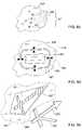
- FIG. 1is an isometric view of a first embodiment of the invention.
- FIG. 2 ashows in cross-sectional view the embodiment of FIG. 1 along X-X;
- FIG. 2 bshows in perspective view a portion of the tray of the embodiment of FIG. 1 corresponding to a single tooth.
- FIGS. 3 a , 3 b and 3 cillustrate alternative window configurations for the embodiment of FIG. 1 .
- FIG. 4shows in cross-sectional view an improvement of the embodiment of FIG. 2 a.
- FIG. 5illustrates in partial isometric view optional features for the embodiment of FIG. 1 .
- FIG. 6illustrates in partial side view a second embodiment of the invention.
- FIG. 7illustrates in partial isometric view a third embodiment of the invention.
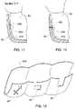
- FIGS. 8 a , 8 b , 8 c , 8 d and 8 eillustrate alternative window configurations for the embodiment of FIG. 7 .
- FIG. 9illustrates a typical bracket configuration which may be used with the present invention.
- FIG. 10is a fragmented isometric view of a fourth embodiment of the invention.
- FIG. 11shows in partial cross-sectional view the embodiment of FIG. 10 along Y-Y.
- FIG. 12shows in partial cross-sectional view an alternative configuration for embodiment of FIG. 10 along Y-Y.
- FIG. 13illustrates in isometric view a fifth embodiment of the invention.
- a first embodiment of the present inventioncomprises a dental targeting device in the form of a tray, generally designated with the numeral 100 , having a plurality of windows 50 .
- the tray 100comprises a U-shaped shell 110 having a plurality of cavities 120 which are shaped to receive teeth.
- the tray 100is designed to fit over an arch 200 regarding which it is desired to provide an orthodontic treatment to at least some of the teeth therein.
- the inside shape of each of the cavities 120is substantially complementary to the external shape of the particular tooth of the arch 200 that is received therein, in particular the lingual and buccal/labial surfaces of the teeth. Accordingly, the tray 100 is designed to fit over the teeth in their current positions, and does not itself require to exert any alignment forces on the teeth, even if manufactured from an elastic material.
- the windows 50each expose a part 60 of a corresponding tooth 90 that is to receive a bracket 70 .
- the windows 50provide targets for enabling each of the brackets 70 to be properly positioned with respect to the teeth that they are to be bonded to.
- Each window 50is appropriately shaped to enable a desired bracket 70 to be inserted therethrough from the outside and onto a tooth, as illustrated in FIG. 2 a , and thus comprises target indicators in the form of all or some of the edges 52 of the window.
- the windowsmay be formed on the buccal/labial side or on the lingual side, or both sides of the cavities in tray 100 , as required.
- the windows 50are each of a shape and size substantially complementary to the shape and size of the desired bracket 70 that is to be fitted therethrough.
- the window 450may be designed to have a target indicators in the form of abutment points 451 or edges (not shown) against which the desired bracket can be abutted to positively fix the position of the bracket with respect to the tray 100 .
- the windowcomprises four corner abutment points 451 with respect to which the corners 71 of the bracket 70 can be positively located.
- the brackets 73may be of a particular shape and/or have some feature such as a notch or protrusion 77 that can help to define some reference datums with respect to the bracket 73 .
- the windowmay comprises a complementary feature, such as a notch 78 to complement protrusion 77 .
- the bracket 73can then be spatially located where desired by bringing together the complementary features 77 and 78 , as illustrated in FIG. 3 c.
- each bracket 70may be positively located on the corresponding tooth 90 via one of the windows 50 (or 450 ) in a position that is fixed relative to the shell 110 when the tray 100 is properly seated over the teeth of arch 200 . Accordingly, the orientation of each of the windows, and the position of each window 50 with respect to the corresponding cavity 120 of the shell 110 , are determined such as will expose the required parts 60 of the teeth on which it is desired to have bonded thereto the brackets 70 .
- the size and shape of the windows 50are also a little larger than those of the particular bracket 70 that is required to be targeted by the window 50 , so that the window 50 does not actually engage the bracket 70 .
- bracket 70typically abuts some or all of the edges or sides 52 of the window 50 , there is sufficient clearance between the window 50 and the bracket 70 to enable the shell 110 to be removed from the arch 200 leaving the brackets behind, and in place on the teeth when they have been bonded thereto.
- the tray 100may be suitably marked, for example by ink or the like using a suitable printing method, or etched or otherwise marked to indicate the optimum paths along which to cut the tray 100 to enable the shell portion 111 comprising the part of cavity 120 corresponding to each individual tooth to be separated from the rest of the tray.
- a shell portion 111may be used to target a bracket onto a particular tooth at almost any point during treatment, when possibly the teeth may have already moved to an extent that would not allow the tray 100 to be properly seated onto the teeth.
- a bracketfalls off a tooth during the middle of an orthodontic treatment. Relative to the corresponding tooth, a particular bracket remains in the same position during the full duration of the treatment.
- the shell portion 111comprises a cavity that substantially follows the shape of the tooth (particularly the buccal and labial sides thereof) that it is designed to fit over, the window 50 of the shell portion will remain in the appropriate place with respect to the tooth when the shell portion 111 is properly seated onto the appropriate tooth.
- the external periphery of the windows 50may comprise a bellmouth entry structure 55 to facilitate aligning the brackets with the windows.
- the target areas 60 for each toothare previously identified, according to a set up plan provided by the orthodontist, as being appropriate for bonding the brackets onto the misaligned teeth of the arch 200 such that the teeth may be aligned in the manner desired in response to the orthodontic treatment.
- Such set up plansmay be provided in any number of ways.
- a plaster model of the patient's dentitionmay be made, typically from an impression taken of the patient's arches, and the individual model teeth are sawed off the model, separated and then aligned as desired.
- a plurality of bracketscan then be positioned on this aligned model corresponding to the final desired orientation of the brackets after the treatment.
- the bracketsshould be substantially aligned on a smooth arc circumscribing the arch 200 .
- the positions of the brackets with respect to each toothcan be mapped back to the original tooth model to provide the location and orientation of the brackets required on the patient's teeth, under the specific orthodontic treatment, to provide the desired alignment of the teeth.
- the desired position and orientation of the bracketsare marked on the model, and this can be done, for example, by temporarily bonding the brackets to the model in the desired positions, for example in the manner used in traditional indirect bonding techniques, for example, which are known per se.
- the position of each of the bracketsmay be marked by circumscribing each bracket with a sharp instrument such as to etch the periphery thereof on the model teeth. The brackets can then be removed, and their positions are clearly marked by the etched peripheries left on the model.
- a tray 100 of transparent materialis formed over the model in any suitable manner, for example as used in traditional indirect bonding techniques, comprising pressure or vacuum forming a suitable sheet material, such as 0.75 mm thermal forming dental material.
- suitable materialsinclude, for example, biocryl, by Great Lakes Orthodontics Ltd., Tonawanda, N.Y.
- a suitable toolsuch as for example a sharp or heated cutting tool, a punch, a laser or a power tool, may be employed to cut windows 50 in registry with the etched peripheries.
- the position of a datum with respect to each bracketmay be marked on the tooth model, for example as a “+” or “X” symbol or mark, such that the center of the mark corresponds to the center or other known location relative to the bracket, and the orientation of the mark is indicative of the orientation of the bracket, for example.
- a reference datummay be referred to a bracket centerline, bracket slot or any other convenient reference on the bracket by which it is possible to place the bracket in a desired position with some accuracy.
- Such symbols or marksmay be provided manually, or by means of a suitable printer, such as for example a laser printer or inkjet printer or via any other suitable method that enables such symbols or marks to be formed on the tray 100 .
- Printing by means of a printeris particularly useful in embodiments wherein the positions of the brackets are determined using a virtual model of the teeth, for example as described hereinbelow.
- pinsmay be attached to the teeth model at these datum positions, such that the pins project from the model teeth substantially orthogonally thereto.
- the pinsproject through the shell and thus provide a guide as to where the windows 50 are to be formed, and the windows may be cut out in a similar manner to that described above, for example.
- two pinsmay be used for each bracket location: one pin fixes the position of the center of the bracket, while a second pin provides information regarding the orientation of the bracket at this position, for example.
- the shell 110may be formed over the model including the brackets in a similar manner to that known in the art, and the brackets 70 together with material of the shell in the vicinity thereof are subsequently removed from the shell 110 such as to form said windows 50 .
- the parts of the shell 110 on which the brackets 70 are attachedhave to be removed very carefully so that the windows 50 indeed permit subsequent aligning of the brackets.
- the three dimensional (3D) structure of the patient's dentitionincluding the teeth that are required to be moved during the course of the orthodontic treatment, and preferably the full dentition of the arch 200 on which these teeth are located, is determined, and provided in digitized form.
- both archesare scanned.
- This structuremay be obtained in any number of ways.
- the intra-oral cavitymay be scanned or imaged using technology known in the art, including X-rays, CT, MRI, using direct contact methods or using non-contact methods such as for example those that employ an optical probe.
- a negative casting of a patient's teethis obtained in a manner well known in the art, and this is used for preparing a positive cast suitable for scanning or imaging.
- the negative modelitself is scanned or imaged.
- a composite positive-negative modelmay be scanned or otherwise imaged to obtain the desired 3D data.
- the dimensional datamay be associated with a complete dentition, or of a partial dentition, comprising the teeth that are to be treated.
- Providing a digitized data set D 1 from such scanning or imagingis also known in the art and will not be described further.
- the digitized data set D 1is manipulable, and thus allows the next step to be performed using a suitable computer.
- the data set D 1is manipulated to provide a final tooth arrangement comprising a final digitized data set D 2 , in which each tooth is positioned in the desired position, for example as described in WO 99/34747 or in U.S. Pat. No. 5,975,893, the contents of which are incorporated herein in their entirety.
- the 3D data corresponding to the individual teeth, DT, of the scanned dentitionare separated from one another, and the user repositions the DT data for each tooth based on visual appearance, using rules or algorithms, or according to prescriptions provided by the orthodontist.
- bracketsare chosen and “virtually” positioned on the aligned teeth virtual model, and the corresponding positions of the brackets are then mapped back to the initial virtual model.
- the position and orientation of the bracketscan be incorporated into the initial dataset D 1 .
- the tray 100may then be manufactured using CNC machining methods, for example, in which the tray 100 may be produced either indirectly or directly.
- Such indirect methodsmay comprise, e.g., manufacturing appropriate inner and outer molds using CNC techniques, and then applying an injection molding technique, for example, for producing a tray 100 from the molds.
- the inner moldcomprises an external 3D structure substantially similar to that defined by dataset D 1
- the outer mouldmay have an internal structure which is also similar to that defined by D 1 , but displaced thereof by a suitable material thickness to provide dataset D 1 ′.
- the CNC machine used for such operationsmay be programmed to provide material removal passes over a blank of material, based on dataset D 1 , such as to provide the molds.
- the windows 50may be integrally formed with the tray 100 , or formed as a separated operation after the tray 100 is produced. Alternatively, the tray may be vacuum formed using only the positive mold thus produced.
- a suitable direct methodmay comprise any suitable material removal operation applied to a suitable material, and carried out using CNC machining techniques based on the datasets D 1 and D 1 ′ of the numerical model.
- the windows 50may be formed during the manufacture of the tray, or as a separate operation after the manufacture of the tray.
- the traymay be formed using other techniques such as described above, and the windows 50 may be formed using CNC machining techniques.
- the spatial position and orientation of tray 100 as a wholemust be known with respect to a machining datum so that machining operations are applied to the desired parts of the tray. If a plaster model of the teeth is available, this may be used for holding the tray steady while the windows are formed.
- the tray 100may be fabricated with indicia that help align the same with respect to predetermined datums in the CNC machine.
- the tray 100is fabricated using other methods.
- the tray 30may be fabricated using rapid prototyping techniques, for example based on a stereolithography machine, such as for example Model SLA-250/50 available from 3D System, Valencia, Calif., based on the dataset D 1 .
- a liquid or non-hardened resinis hardened into a 3D form that can be separated from the non-hardened liquid or resin to form a positive model of the arch 200 from the 3D numerical model thereof.
- a tray 100may be formed over the positive model in a similar manner to that described above, for example, Alternatively, an outer mold for the external surface of the tray 100 is produced in a similar manner to that described for the positive model, mutatis mutandis, and injection techniques are used to provide the tray 100 using the outer mold and the positive model.
- the tray 100is preferably made from a flexible material, but may also be made from a rigid or semi rigid material, including for example some rigid plastics, which may be easier to machine using CNC methods, for example.
- the tray 100it is thus possible for the tray 100 to be fabricated at one location, and then transported to another location where the windows 50 are formed, or for the finished tray 100 including windows 50 to be fabricated at a single location.
- the windows 50thus provided enable brackets 70 to be targeted and placed onto the desired areas 60 of the tooth model, and thus also of the patient's teeth when the tray 100 is properly seated thereonto.
- the tray 100may be suitably marked in the vicinity of each window 50 with an identifying mark, symbol or alphanumeric character, for example, that identifies the bracket 70 that is supposed to be targeted onto and bonded to the tooth via that window 50 .
- an identifiermay be printed, etched or in any other manner provided on the tray 100 .
- Each window 50is thus formed for enabling a particular bracket to be brought into contact and required alignment with the required part 60 of the tooth where it is desired to bond the bracket to.
- alignmentcomprises the spatial disposition of the bracket with respect to the corresponding tooth and includes the position and orientation of the bracket over the tooth surface.
- each window 50is independent from the other windows. Accordingly, for any given tray 100 , windows 50 therein can be formed to accommodate the same brand of brackets or alternatively a mixture of different brands of brackets, and/or brackets of different sizes, families or slot widths, and so on.
- Placement of the brackets in the intraoral cavitycan be effected in a number of ways.
- the tray 100having been manufactured to include windows 50 where desired therein, is seated onto the arch 200 so that each tooth thereof fits snugly within the corresponding cavity 120 , leaving exposed parts 60 of the teeth.
- the orthodontist, or indeed any other care giver that is providing the orthodontic treatmentthen takes each bracket 70 in turn and positions it in the appropriate window 50 so that the bracket 70 is guided by the window into alignment with the corresponding tooth, and abuts the part 60 of the corresponding tooth.
- the part 60 of each toothis etched prior to placement of the brackets to provide improved bonding with respect to the bracket 70 .
- Etchingcan be performed as is known in the art, and it is possible to etch on each tooth a general area where it is known that will include the part 60 .
- the part 60is etched through the window 50 .
- the position of the window 50 with respect to each toothmay be marked using any suitable marking device, such as a pen or a stamp for example, and the tray is removed, allowing the marked area to be etched.
- a suitable adhesivePrior to positioning the bracket, either the bracket 70 or the part 60 of the tooth, or both are coated with a suitable adhesive.
- the adhesivemay be, for example, a chemical adhesive, and sets within a predetermined time period, and thus the tray 100 helps to maintain the brackets 70 in their desired positions until the adhesive sets, whereupon the tray 100 may be removed.
- the adhesivemay be light cured, in which case the tray is preferably transparent to enable the brackets to remain in place while the adhesive is cured with light shone thereat from a suitable source.
- the tray 100is removed from the arch 200 .
- the natural elasticity thereofenables the tray to be stretched over the brackets to enable the tray to be removed without interfering with the brackets.
- the tray 100may be cut, for example along the part thereof corresponding to the cusps of the teeth, to remove the tray 100 in two halves.
- This slot 58may be cut after the bracket 70 has been bonded in position.
- the tray 100may comprise fracture lines 57 along the edges of the slot, to enable the strip 53 to be easily pulled off by the practitioner.
- a single fracture linemay be provided, preferably intermediate to the illustrated lines 57 or alternatively elsewhere, for example radiating outwardly from the window for a short distance, and preferably extending to the edge 130 , for opening up the tray at least in the vicinity of the window.
- a tab 52may be formed at one end of the strip 53 to facilitate grasping of the same so that the strip may be pulled off more efficiently.
- the windows 50may be used as targets for marking the parts 60 of the teeth onto which the brackets 70 are to be bonded.
- a suitable marking implementsuch as a pen, pencil, printing pad or the like, for example, may be used to mark the area exposed by the window 50 , in ink for example, this mark delineating the position required for the bracket 70 , for each tooth.
- the tray 100may be removed from the arch 200 . Thereafter, each bracket 70 may be positioned and bonded onto the appropriate part 60 by placing the bracket in registry with the corresponding mark, the bracket 70 and/or the part 60 having previously been provided with a suitable adhesive, and where appropriate curing the adhesive.
- the tray 100 ′comprises all the elements and features of the first embodiment, as described herein mutatis mutandis, with the following difference.
- the tray 100 ′comprises slots 58 ′ that are integrally formed with the windows 50 ′.
- the width of the slot 58 ′is substantially equivalent to the projected width w′ of the bracket taken along the insertion path IP of the tray 100 ′, and the edges 57 ′ of the slot 58 ′ are substantially parallel to this path, preferably.
- the edges 57 ′may be flared, in a preferably divergent manner towards the free edge 130 , but possibly also convergent manner, from the window 50 ′.
- the window 50 ′has an open end 51 ′, and further comprises target indicators in the form of abutment edges that are sufficient to enable the corresponding bracket to be spatially fixed in two dimensions, i.e., over the surface of the corresponding tooth when the tray is seated thereon.
- target indicatorsin the form of abutment edges that are sufficient to enable the corresponding bracket to be spatially fixed in two dimensions, i.e., over the surface of the corresponding tooth when the tray is seated thereon.
- the corresponding window 150 ′comprises a single abutment edge 151 ′ to define the position and orientation of the bracket 70 ′ along the direction of the insertion path.
- the width w′ of the window 150 ′ensures that the bracket position in the direction orthogonal to the insertion path is fixed.
- the corresponding window 150 ′′comprises two abutment edges 151 ′′ to define the position and orientation of the bracket 70 ′′ along and orthogonal to the direction of the insertion path.
- Brackets of other shapesrequire one or more abutment edges, according to the geometry of the brackets.
- the tray 100 ′ according to the second embodimentmay be designed and manufactured in a similar manner to that described herein for the first embodiment, mutatis mutandis, with the difference that rather than just the windows, the windows are formed with the aforesaid slots, either concurrently, or after the windows are formed.
- the tray 100 ′ according to this embodimentmay also be used in a similar manner to that described for the first embodiment, mutatis mutandis, with the difference that each bracket is positioned with respect to the corresponding abutment edges of the window. Removal of the tray 100 ′ is simply by lifting the tray 100 ′ away from the arch 200 in a direction opposed to the insertion path. Where the tray 100 ′ is used to mark the area 60 , this part plus another portion of the tooth exposed by the slot 58 ′ may be marked in a similar manner to that described for window 50 of the first embodiment. Alternatively, only the appropriate abutment edges need to be marked, as these provide sufficient targeting information for each bracket. Once the teeth are marked thus, each bracket may be positioned and bonded onto the appropriate part of the tooth by placing the bracket in registry with the corresponding mark, the bracket and/or the part 60 having previously been provided with a suitable adhesive, and where appropriate curing the adhesive.
- the tray 100 ′′comprises all the elements and features of the first embodiment, as described herein mutatis mutandis, with the following difference.
- the tray 100 ′′rather than the windows being in a form complementary to the shape of the brackets, the windows 50 ′′ are of a shape that allow the corresponding parts 60 to be marked in a manner that permits the brackets 70 to be subsequently targeted after the tray 100 ′′ is removed.
- windows 50 ′′may be in the form of a symbol, for example slits such as cross-hairs “+” or “X”, which act as indirect target indicators.
- slitssuch as cross-hairs “+” or “X”
- a window 50 ′′may be in the form of a slit 310 in the shape of an arrow 314 and having a cross-member 315 intersecting this at 316 .
- the intersection point 316is representative of the center of the bracket, while arrow 314 points the direction of a datum reference line of the bracket.
- window 50 ′′may be in the form of a slit 320 in the shape of a line 324 and having a disc at 326 .
- the disc 326is representative of the center of the bracket, while line 324 points the direction of a datum line of the bracket.
- Many other formsare possible for the window 50 ′′.
- a plurality of windows 356each in the shape of a slot or round hole, for example, are provided, and provided in a recognizable pattern. Together, the windows 356 define the spatial location and orientation of the bracket. Any marking method may be used to mark the tooth surface via the windows 356 —for example, ink, or by using a sharp instruments through the windows 356 to scratch the tooth surface. When the shell is removed, the markings are left behind, and the appropriate bracket can be aligned with respect to the marks.
- the window 357may be of a size greater than the bracket 358 , and comprise appropriate markings 359 along the periphery of the window 357 .
- the markings 359may be transferred to the tooth surface manually by scratching the tooth or otherwise marking the same with ink or the like at locations juxtaposed to the markings, and when the shell 110 is removed, the bracket is aligned with respect to these marks.
- the bracket 358is advantageously provided width alignment marks 351 which are arranged to match the positions of marks 359 .
- the bracket 358may be aligned directly with the markings 359 while the shell is on the arch 200 , and after bonding the tray 110 is removed.
- brackets 70may be marked to show a datum centerline 74 , bracket slot position 76 , or other geometrical references or datum references of the bracket.
- the tray 100 ′′ according to the third embodimentmay be designed and manufactured in a similar manner to that described herein for the first embodiment, mutatis mutandis, with the difference that rather than windows 50 , the windows 50 ′′ are formed instead.
- the tray 100 ′′ according to this embodimentmay also be used in a similar manner to that described for the first embodiment where the positions of the brackets are marked by means of the tray, mutatis mutandis.
- the tray 100 ′′is seated onto the arch 200 so that the windows 50 ′′ are superposed or in registry with the corresponding parts 60 onto which the brackets 70 are eventually to be positioned, leaving exposed a small area 66 of this part in the shape of the corresponding window 50 ′′.
- This area 66may be marked in a similar manner to that described for window 50 of the first embodiment, for example by means of a fine pen or pencil or the like, or for example by using a coloring pad.
- Such a padmay hold a quantity of ink or other pigment, and when brought into contact with the outside of the tray 100 ′′ in the vicinity of each window 50 ′′, the color or pigment only colors the exposed area 66 of the corresponding tooth.
- the windowis of a predetermined shape, for example the shape of as kite, as illustrated in FIG. 8 e , and a printing implement in the form of a wand 350 having at its extremity a printing pad 355 of an appropriate shape is used to mark the part 60 with a targeting mark 360 .
- the window 50 ′′is used to enable the printing pad to be properly oriented and positioned with respect to the tray 100 ′′, and in turn the printing pad comprises a printing symbol that is indicative of position and orientation of the bracket that it is desired to place there.
- a symbolmay be similar, for example, to the shapes of the windows described in respect of FIGS. 8 a to 8 d .
- the tray 100 ′′ according to the third embodimentis particularly advantageous since it permits the choice of actual bracket to be deferred if necessary, for example due to logistical problems in obtaining specific marks of brackets. Since the positional data required for the bracket is marked using the tray 100 ′′, it is possible to target any bracket to a particular target marked with the tray 100 ′′, so long as the bracket comprises suitable datums compatible with the marking criteria used for the target symbol, for example centerline and slot location datums.
- the tray 600comprises all the elements and features of the other embodiment, as described herein mutatis mutandis, with the following difference.
- the tray 600comprises a shell 610 similar to shell 110 of the previous embodiments, but does not comprise windows.
- transfer means 650are provided in the inside of the cavities 620 to transfer target information to the corresponding tooth regarding where the bracket 70 is to be located and bonded.
- the transfer means 650may comprise a pad or the like containing a transfer material including, for example, ink or other staining pigment, or an etching acid or the like, for example.
- the padwhen the appropriate tooth is received in the cavity containing the pad, the pad can be pressed against the tooth, transferring or printing thereon the transfer material in the shape of the pad and in the correct position with respect to the tooth.
- the padmay be in a form complementary to the shape of the brackets, and thus allow the corresponding parts 60 to be marked in a manner that permits the brackets 70 to be subsequently targeted after the tray 600 is removed.
- the padsmay be in the form of a symbol, for example cross-hairs in the form of “+” or “X”, or a series of dots or lines in a recognizable pattern, or arrows, or any other suitable shape, which act as indirect target indicators.
- the transfer padmay contain a transfer patch of a suitable material that is transferred to the tooth.
- the transfer patchmay comprise an adhesive label that is transferred to the tooth.
- the adhesive labelmay be, for example, in the shape of the periphery of the required bracket, so that the bracket may be fitted in the open area in the patch after the patch is adhered to the tooth.
- the adhesive patchmay comprise a chemical or light-cured adhesive, which sets when the tooth has been properly seated in the appropriate cavity and the patch aligned on the tooth.
- the patchmay be a series of dots or lines which together define the spatial location and orientation of the bracket.
- the patchmay comprise adhesive on both sides thereof, enabling the patch to first bond onto the tooth, and then allow the bracket to be bonded to the patch.
- each adhesivemay be selectively activated independently of the other.
- the adhesivesmay be light-curing adhesives, each of which cures at a different wavelength. This facilitates the procedure of bonding the patch to the tooth first, and then allowing the bracket to be bonded to the patch.
- the patchmay be in the form or shape of the bracket, or in any other suitable shape such as to guide the bracket to the required alignment with respect thereto and thus the tooth.
- the transfer meansmay comprise a sharp protrusion 655 of appropriate shape and size.
- the appropriate toothis received in the cavity 620 containing the protrusion, this can be pressed against the tooth 90 , scratching thereon marks in the shape of the protrusion and in the correct position with respect to the tooth.
- the protrusionmay be in a form complementary to the shape of the brackets, and thus allow the corresponding parts 60 to be marked in a manner that permits the brackets 70 to be subsequently targeted after the tray 600 is removed.
- the protrusionmay be in the form of a symbol, for example cross-hairs in the form of “+” or “X”, or a series of dots or lines in a recognizable pattern, or arrows, or any other suitable shape, which act as indirect target indicators.
- the markingsare left behind, and the appropriate bracket can be aligned with respect to the marks.
- the tray 600may also be used in a similar manner to that described for the other embodiments where the positions of the brackets are marked by means of the tray, mutatis mutandis.
- the tray 600is seated onto the arch 200 so that the transfer means 650 are in registry with the corresponding parts 60 onto which the brackets 70 are eventually to be positioned.
- the orthodontistthen presses the transfer means against the appropriate tooth, leaving a mark or adhesive patch on the area 60 , according to the type of transfer mans used.
- these markingsprovide sufficient targeting information for each bracket to be aligned on the tooth.
- the tray 600is then removed by lifting the tray 600 away from the arch 200 in a direction opposed to the insertion path.
- each bracketmay be positioned and bonded onto the appropriate part of the tooth by placing the bracket in registry with the corresponding mark, the bracket and/or the part 60 having previously been provided with a suitable adhesive, and where appropriate curing the adhesive.
- the tray 600 according to the this embodimentis also particularly advantageous since it permits the choice of actual bracket to be deferred if necessary, for example due to logistical problems in obtaining specific marks of brackets. Since the positional data required for the bracket is marked using the tray 600 , it is possible to target any bracket to a particular target marked with the tray 600 , so long as the bracket comprises suitable datums compatible with the marking criteria used for the target symbol, for example centerline and slot location datums.
- the tray 600 according to this embodimentmay be manufactured in a similar manner to that described above for the other embodiments with the following differences, mutatis mutandis.
- the tray according to this embodimentis provided with the transfer means 650 , typically after the basic shell 610 has been fabricated, but optionally also integrally therewith.
- the transfer means 650are located in the shell using any suitable computer controlled or other navigation technique for locating the means in their correct positions.
- the transfer meansmay be temporarily mounted onto a positive tooth model, and then the tray is vacuum formed over the model, so that when the tray is removed, the transfer means are carried by the tray.
- the traymay comprise any combination and permutation of windows according to the first embodiment, and/of the windows according to the second embodiment, and/or the windows according to the third embodiment, and/or of the transfer means of the fourth embodiment, mutatis mutandis.
- a tray 500is provided which is substantially similar to a portion of the full tray according to any of the other embodiments described herein.
- the tray 500thus comprises all the elements and features of these embodiments, as described herein mutatis mutandis, wherein the tray portion 500 is adapted to be placed over one or several teeth, rather than over the full arch 200 .
- the tray 500may comprise any one of or a combination of the windows according to any embodiment.
- the tray 500is adapted to be seated over three adjacent teeth, and comprises windows 50 , 50 ′ and 50 ′′.
- the tray 500 according to the fifth embodimentmay be designed and manufactured in a similar manner to that described herein for the first, second, third or fourth embodiments, mutatis mutandis, with the difference that rather than a complete tray, only the relevant part of the tray is formed instead.
- the tray 500 according to this embodimentmay also be used in a similar manner to that described for the first, second, third or fourth embodiments, mutatis mutandis.
- the tray 500is seated onto the appropriate teeth of arch 200 so that the windows are in registry with the corresponding parts 60 of the teeth onto which the brackets 70 are eventually to be positioned.
- the bracketsmay be targeted onto these parts directly via the windows, or indirectly by using the windows to mark the teeth in an appropriate manner, or by marking the positions of the brackets as described for the fourth embodiment, and bonded onto the teeth.
- the tray 500is removed by lifting the same away from the arch 200 in a direction opposed to the insertion path.
- the tray 500 according to the fifth embodimentis particularly useful in permitting brackets to be placed in only one or some of the teeth without the necessity of providing a full tray. Such a capability is of particular advantage when it is desired to add or replace a number of brackets to the teeth after the teeth have been moved by some amount.
- the tray 500When the tray 500 is for a single tooth it may not even be necessary to provide another model of the dentition (physical or virtual). Relative to the tooth, the bracket remains in the same position during the full duration of the treatment. Since the tray 500 comprises a cavity that substantially follows the shape of the tooth it is designed to fit over, the window of the tray will remain in the appropriate place with respect to the tooth when the tray 500 is properly seated onto the appropriate tooth. Thus, the original tooth model may be used to provide the geometrical information required to produce the tray 500 .
- the traywith useful information including, for example, at least one of: the name of the patient; the name of the orthodontist; the name of the dental lab that manufactured the tray; the date of manufacture; the model, type, serial numbers, or other identifying references for the brackets; and so on.
Landscapes
- Health & Medical Sciences (AREA)
- Oral & Maxillofacial Surgery (AREA)
- Dentistry (AREA)
- Epidemiology (AREA)
- Life Sciences & Earth Sciences (AREA)
- Animal Behavior & Ethology (AREA)
- General Health & Medical Sciences (AREA)
- Public Health (AREA)
- Veterinary Medicine (AREA)
- Dental Tools And Instruments Or Auxiliary Dental Instruments (AREA)
Abstract
Description
- a shell comprising, for the or each tooth with respect to which it is desired to align a said orthodontic element, a cavity shaped to receive the tooth, and further comprising targeting indicators configured for enabling the corresponding said orthodontic element to be guided into alignment in said predetermined manner with respect to a said tooth that is received in a corresponding said cavity.
- (A) providing target indicators for the or each tooth with respect to which it is desired to align a said orthodontic element, and for said each orthodontic element in turn:
- (B) bringing said orthodontic element into proximity with corresponding said targeting indicators; and
- (C) aligning said orthodontic element with respect to said targeting indicators to achieve the required said alignment of the element with respect to the tooth accommodated in the corresponding said cavity.
- (a) providing a shell comprising, for the or each tooth with respect to which it is desired to align a said orthodontic element, a cavity shaped to receive the tooth, and further comprising targeting indicators configured for guiding the or each said orthodontic element into alignment in said predetermined manner with respect to a said tooth that is received in a corresponding said cavity;
- (b) seating said shell over said teeth such that the or each said tooth is received in a respective said cavity; and for said each orthodontic element in turn:
- (c) bringing said orthodontic element into proximity with corresponding said targeting indicators; and
- (d) aligning said orthodontic element with respect to said targeting indicators to achieve the required said alignment of the element with respect to the tooth accommodated in the corresponding said cavity.
Claims (18)
Priority Applications (3)
| Application Number | Priority Date | Filing Date | Title |
|---|---|---|---|
| US11/105,355US7347688B2 (en) | 2004-04-15 | 2005-04-14 | Dental targetting device and method |
| US11/808,171US20070238066A1 (en) | 2004-04-15 | 2007-06-07 | Dental targetting device and method |
| US11/889,001US20070275340A1 (en) | 2004-04-15 | 2007-08-08 | Dental targetting device and method |
Applications Claiming Priority (2)
| Application Number | Priority Date | Filing Date | Title |
|---|---|---|---|
| US56231604P | 2004-04-15 | 2004-04-15 | |
| US11/105,355US7347688B2 (en) | 2004-04-15 | 2005-04-14 | Dental targetting device and method |
Related Child Applications (1)
| Application Number | Title | Priority Date | Filing Date |
|---|---|---|---|
| US11/808,171ContinuationUS20070238066A1 (en) | 2004-04-15 | 2007-06-07 | Dental targetting device and method |
Publications (2)
| Publication Number | Publication Date |
|---|---|
| US20050233276A1 US20050233276A1 (en) | 2005-10-20 |
| US7347688B2true US7347688B2 (en) | 2008-03-25 |
Family
ID=35096674
Family Applications (3)
| Application Number | Title | Priority Date | Filing Date |
|---|---|---|---|
| US11/105,355Active2025-11-11US7347688B2 (en) | 2004-04-15 | 2005-04-14 | Dental targetting device and method |
| US11/808,171AbandonedUS20070238066A1 (en) | 2004-04-15 | 2007-06-07 | Dental targetting device and method |
| US11/889,001AbandonedUS20070275340A1 (en) | 2004-04-15 | 2007-08-08 | Dental targetting device and method |
Family Applications After (2)
| Application Number | Title | Priority Date | Filing Date |
|---|---|---|---|
| US11/808,171AbandonedUS20070238066A1 (en) | 2004-04-15 | 2007-06-07 | Dental targetting device and method |
| US11/889,001AbandonedUS20070275340A1 (en) | 2004-04-15 | 2007-08-08 | Dental targetting device and method |
Country Status (1)
| Country | Link |
|---|---|
| US (3) | US7347688B2 (en) |
Cited By (107)
| Publication number | Priority date | Publication date | Assignee | Title |
|---|---|---|---|---|
| US20070087302A1 (en)* | 2002-12-31 | 2007-04-19 | Reising Brian C | Orthodontic bracket and method of attaching orthodontic brackets to teeth |
| US20090220920A1 (en)* | 2005-03-01 | 2009-09-03 | Primus Carolyn M | Methods for indirect bonding of orthodontic appliances |
| US20100086899A1 (en)* | 2007-01-03 | 2010-04-08 | Etkon Centrum Für Dentale Cad/Cam-Tecnologie Ag | Method concerning the modelling and production of a set of artificial teeth |
| US20100151417A1 (en)* | 2007-05-25 | 2010-06-17 | Nobel Biocare Services Ag | Method and system for dental planning |
| US20100159413A1 (en)* | 2008-12-18 | 2010-06-24 | Align Technology, Inc. | Uv and chemical cure blocking dental template |
| US20100216085A1 (en)* | 2009-02-24 | 2010-08-26 | Cadent Ltd. | Method, system and model for indirect bonding |
| US9707056B2 (en) | 2013-03-06 | 2017-07-18 | American Orthodontics Corporation | Indirect bonding tray and method of manufacture thereof |
| US20180168788A1 (en)* | 2016-12-16 | 2018-06-21 | Align Technology, Inc. | Dental appliance etch template |
| WO2018195356A1 (en)* | 2017-04-21 | 2018-10-25 | Swift Health Systems Inc. | Indirect bonding trays, non-sliding orthodontic appliances, and registration systems for use thereof |
| US10219877B2 (en) | 2012-10-30 | 2019-03-05 | University Of Southern California | Orthodontic appliance with snap fitted, non-sliding archwire |
| US10335250B2 (en) | 2015-10-07 | 2019-07-02 | uLab Systems, Inc. | Three-dimensional printed dental appliances using lattices |
| US10357336B2 (en) | 2015-10-07 | 2019-07-23 | uLab Systems, Inc. | Systems and methods for fabricating dental appliances or shells |
| US10357342B2 (en) | 2016-09-21 | 2019-07-23 | uLab Systems, Inc. | Digital dental examination and documentation |
| WO2019241251A1 (en)* | 2018-06-12 | 2019-12-19 | Lightforce Orthodontics, Inc. | Ceramic processing and design for the direct manufacture of customized labial and lingual orthodontic clear aligner attachments |
| US10548690B2 (en) | 2015-10-07 | 2020-02-04 | uLab Systems, Inc. | Orthodontic planning systems |
| US10624717B2 (en) | 2015-10-07 | 2020-04-21 | Ulab Systems Inc. | Tooth modeling system |
| US10631953B2 (en) | 2015-10-07 | 2020-04-28 | uLab Systems, Inc. | Three-dimensional printed dental appliances using support structures |
| TWI707667B (en)* | 2019-12-13 | 2020-10-21 | 柯百俞 | Transparent braces with lines in the moving direction |
| US20200331171A1 (en)* | 2014-05-21 | 2020-10-22 | Align Technology, Inc. | Mold with separable features |
| US10828133B2 (en) | 2016-12-02 | 2020-11-10 | Swift Health Systems Inc. | Indirect orthodontic bonding systems and methods for bracket placement |
| US10881489B2 (en) | 2017-01-31 | 2021-01-05 | Swift Health Systems Inc. | Hybrid orthodontic archwires |
| US10905527B2 (en) | 2015-12-06 | 2021-02-02 | Brius Technologies, Inc. | Teeth repositioning systems and methods |
| US10952821B2 (en) | 2016-09-21 | 2021-03-23 | uLab Systems, Inc. | Combined orthodontic movement of teeth with temporomandibular joint therapy |
| US11058518B2 (en) | 2019-05-02 | 2021-07-13 | Brius Technologies, Inc. | Dental appliances, systems and methods |
| US11109946B2 (en) | 2019-09-16 | 2021-09-07 | Align Technology, Inc. | Durable ornamental indicia carrier |
| US11194312B2 (en) | 2017-03-31 | 2021-12-07 | Align Technology, Inc. | Orthodontic appliances including at least partially un-erupted teeth and method of forming them |
| US11304778B2 (en) | 2016-06-17 | 2022-04-19 | Align Technology, Inc. | Intraoral appliances with proximity and contact sensing |
| US11364098B2 (en) | 2016-09-21 | 2022-06-21 | uLab Systems, Inc. | Combined orthodontic movement of teeth with airway development therapy |
| US20220212297A1 (en)* | 2009-02-02 | 2022-07-07 | Viax Dental Technologies Llc | Method for Producing a Dentist Tool |
| US11471250B2 (en) | 2010-04-30 | 2022-10-18 | Align Technology, Inc. | Reinforced aligner hooks |
| US11490995B2 (en) | 2021-03-25 | 2022-11-08 | Brius Technologies, Inc. | Orthodontic treatment and associated devices, systems, and methods |
| US11510755B2 (en)* | 2018-02-07 | 2022-11-29 | Ormco Corporation | Custom dental attachment placement appliances and appliance manufacturing methods |
| US11576766B2 (en) | 2017-06-26 | 2023-02-14 | Align Technology, Inc. | Biosensor performance indicator for intraoral appliances |
| US11576754B2 (en) | 2016-12-02 | 2023-02-14 | Align Technology, Inc. | Methods and apparatuses for customizing a rapid palatal expander |
| US11583365B2 (en) | 2015-10-07 | 2023-02-21 | uLab Systems, Inc. | System and methods for tooth movement as a flock |
| US11602414B2 (en) | 2019-06-11 | 2023-03-14 | Align Technology, Inc. | Aligner material, cleanliness, and quality detection via aligner case |
| US11612458B1 (en) | 2017-03-31 | 2023-03-28 | Swift Health Systems Inc. | Method of tongue preconditioning in preparation for lingual orthodontic treatment |
| US11612455B2 (en) | 2016-06-17 | 2023-03-28 | Align Technology, Inc. | Orthodontic appliance performance monitor |
| US11648090B2 (en) | 2012-05-14 | 2023-05-16 | Align Technology, Inc. | Multilayer polymer sheets |
| US11661468B2 (en) | 2020-08-27 | 2023-05-30 | Align Technology, Inc. | Additive manufacturing using variable temperature-controlled resins |
| US11701203B2 (en) | 2018-06-29 | 2023-07-18 | Align Technology, Inc. | Dental appliance hook placement and visualization |
| US11718019B2 (en) | 2018-09-14 | 2023-08-08 | Align Technology, Inc. | System for hybrid 3D printing with photo-curable materials |
| US11723748B2 (en) | 2019-12-23 | 2023-08-15 | Align Technology, Inc. | 2D-to-3D tooth reconstruction, optimization, and positioning frameworks using a differentiable renderer |
| US11744678B2 (en) | 2014-08-22 | 2023-09-05 | Align Technology, Inc. | Attachment structure |
| US11752030B2 (en) | 2015-01-13 | 2023-09-12 | Align Technology, Inc. | Systems and methods for positioning a patient's mandible in response to sleep apnea status |
| US11771531B2 (en) | 2015-01-13 | 2023-10-03 | Align Technology, Inc. | Mandibular advancement and retraction via bone anchoring devices |
| US11771527B2 (en) | 2019-02-20 | 2023-10-03 | Sdc U.S. Smilepay Spv | Limited wear aligner and treatment methods |
| US11786341B2 (en) | 2019-12-09 | 2023-10-17 | Align Technology, Inc. | Occlusal block design for lateral locking |
| US11793667B2 (en) | 2015-01-13 | 2023-10-24 | Align Technology, Inc. | Systems, methods, and devices for applying distributed forces for mandibular advancement |
| US11793608B2 (en) | 2017-11-01 | 2023-10-24 | Align Technology, Inc. | Systems and methods for correcting malocclusions of teeth |
| US11845868B2 (en) | 2020-03-13 | 2023-12-19 | Align Technology, Inc. | Weak covalent crosslinks in thermoset materials for increased toughness |
| US11851510B2 (en) | 2020-03-02 | 2023-12-26 | Align Technology, Inc. | Low viscosity photo-curable resins for the direct fabrication of orthodontic appliances |
| US11883256B2 (en) | 2017-10-05 | 2024-01-30 | Align Technology, Inc. | Methods of forming interproximal reduction templates |
| US11939287B2 (en) | 2021-06-24 | 2024-03-26 | Align Technology, Inc. | Recovery of monomeric and oligomeric building blocks from polymeric materials |
| US11944514B2 (en) | 2015-07-07 | 2024-04-02 | Align Technology, Inc. | Methods for fabricating dental appliances with integrally formed components |
| US11957533B2 (en) | 2019-12-31 | 2024-04-16 | Align Technology, Inc. | Aligner stage analysis to obtain mechanical interactions of aligners and teeth for treatment planning |
| US11963842B2 (en) | 2015-07-07 | 2024-04-23 | Align Technology, Inc. | Appliances for intraoral delivery of agents |
| US11969311B2 (en) | 2020-12-14 | 2024-04-30 | Align Technology, Inc. | Replacement attachment system |
| US11992386B2 (en) | 2009-03-19 | 2024-05-28 | Align Technology, Inc. | Methods of dental wire attachment |
| US11992383B2 (en) | 2021-06-23 | 2024-05-28 | uLab Systems, Inc. | System for force measurement upon orthodontic appliances |
| US20240189074A1 (en)* | 2022-12-08 | 2024-06-13 | 2860296 Ontario lnc. | Apparatus, system and method for direct bonding of orthodontic brackets |
| US12011332B2 (en) | 2008-06-12 | 2024-06-18 | Align Technology, Inc. | Methods of forming dental tooth positioning appliances |
| US12016741B2 (en) | 2017-03-16 | 2024-06-25 | Viax Dental Technologies Llc | System for preparing teeth for the placement of veneers |
| US12023217B2 (en) | 2006-10-20 | 2024-07-02 | Align Technology, Inc. | Positioning three-dimensional brackets on teeth |
| US12023846B2 (en) | 2009-08-13 | 2024-07-02 | Align Technology, Inc. | Method of forming a dental appliance |
| USD1035006S1 (en) | 2022-09-12 | 2024-07-09 | Align Technology, Inc. | Dental aligner storage case |
| US12029623B2 (en) | 2015-07-07 | 2024-07-09 | Align Technology, Inc. | Dental materials using thermoset polymers |
| US12036086B2 (en) | 2008-05-23 | 2024-07-16 | Align Technology, Inc. | Orthodontic tooth movement device, systems and methods |
| US12042353B2 (en) | 2018-05-04 | 2024-07-23 | Align Technology, Inc. | Curable composition for use in a high temperature lithography-based photopolymerization process and method of producing crosslinked polymers therefrom |
| US12042354B2 (en) | 2019-03-01 | 2024-07-23 | Swift Health Systems Inc. | Indirect bonding trays with bite turbo and orthodontic auxiliary integration |
| US12049528B2 (en) | 2021-04-23 | 2024-07-30 | Align Technology, Inc. | Photopolymerizable block polymers and methods of producing and using the same |
| US12048606B2 (en) | 2015-02-23 | 2024-07-30 | Align Technology, Inc. | Systems for treatment planning with overcorrection |
| US12053345B2 (en) | 2021-09-03 | 2024-08-06 | Swift Health Systems Inc. | Method of administering adhesive to bond orthodontic brackets |
| US12053346B2 (en) | 2019-10-31 | 2024-08-06 | Swift Health Systems Inc. | Indirect orthodontic bonding systems and methods |
| US12059321B2 (en) | 2008-01-29 | 2024-08-13 | Align Technology, Inc. | Orthodontic repositioning appliances having improved geometry, methods and systems |
| US12064315B2 (en) | 2019-04-30 | 2024-08-20 | uLab Systems, Inc. | Indirect bonding tray system |
| WO2024137942A3 (en)* | 2022-12-23 | 2024-08-29 | Alta Smiles Llc | Combined aligner and direct bonding wire system and method |
| US12076208B2 (en) | 2020-07-31 | 2024-09-03 | Align Technology, Inc. | Direct fabrication of mixed metal and polymer orthodontic devices |
| US12090025B2 (en) | 2020-06-11 | 2024-09-17 | Swift Health Systems Inc. | Orthodontic appliance with non-sliding archform |
| US12097085B2 (en) | 2018-04-11 | 2024-09-24 | Align Technology, Inc. | Palatal expanders with breach regions |
| US12098227B2 (en) | 2020-08-31 | 2024-09-24 | Align Technology, Inc. | 3D printed composites from phase separated materials |
| USD1043994S1 (en) | 2022-01-06 | 2024-09-24 | Swift Health Systems Inc. | Archwire |
| US12121411B2 (en) | 2020-08-19 | 2024-10-22 | uLab Systems, Inc. | Smile treatment planning systems and methods |
| US12144705B2 (en) | 2015-02-23 | 2024-11-19 | Align Technology, Inc. | Systems and methods for induction of biological response in support structures of the teeth and repositioning thereof |
| US12144700B2 (en) | 2020-11-05 | 2024-11-19 | Brius Technologies, Inc. | Dental appliances and associated systems and methods |
| US12150831B2 (en) | 2016-09-21 | 2024-11-26 | uLab Systems, Inc. | Combined orthodontic movement of teeth with cosmetic restoration |
| US12152092B2 (en) | 2018-05-04 | 2024-11-26 | Align Technology, Inc. | Polymerizable monomers and method of polymerizing the same |
| US12178678B2 (en) | 2012-09-06 | 2024-12-31 | Align Technology, Inc. | Method and a system usable in creating a subsequent dental appliance |
| US12193906B2 (en) | 2015-07-07 | 2025-01-14 | Align Technology, Inc. | Systems for fabricating orthodontic appliances with power arms |
| US12193908B2 (en) | 2021-09-03 | 2025-01-14 | Swift Health Systems, Inc. | Orthodontic appliance with non-sliding archform |
| US12226279B2 (en) | 2015-07-07 | 2025-02-18 | Align Technology, Inc. | Methods of forming appliances for arch expansion |
| US12226281B2 (en) | 2020-02-24 | 2025-02-18 | Align Technology, Inc. | Flexible 3D printed orthodontic device with attachment supports |
| US12226280B2 (en) | 2020-01-21 | 2025-02-18 | Align Technology, Inc. | Direct fabrication of orthodontic appliances with 4D printing |
| US12226284B2 (en) | 2014-05-21 | 2025-02-18 | Align Technology, Inc. | Generating a virtual 3D model of a mold |
| US12232929B2 (en) | 2014-02-21 | 2025-02-25 | Align Technology, Inc. | Methods and devices for jaw repositioning |
| US12251288B2 (en) | 2016-02-17 | 2025-03-18 | Align Technology, Inc. | Variable direction tooth attachments |
| US12251287B2 (en) | 2016-12-19 | 2025-03-18 | Align Technology, Inc. | Aligners with enhanced gable bends |
| US12268571B2 (en) | 2021-03-12 | 2025-04-08 | Swift Health Systems Inc. | Indirect orthodontic bonding systems and methods |
| US12329605B2 (en) | 2017-07-27 | 2025-06-17 | Align Technology, Inc. | Surgical stabilizer aligner sets |
| US12329602B2 (en) | 2020-10-09 | 2025-06-17 | Align Technology, Inc. | Modular fabrication of dental apparatuses |
| US12350121B2 (en) | 2014-11-12 | 2025-07-08 | Align Technology, Inc. | Orthodontic aligner with isolated segments |
| US12383377B2 (en) | 2015-07-07 | 2025-08-12 | Align Technology, Inc. | Methods for designing attachment placement appliances |
| US12403380B2 (en) | 2008-11-24 | 2025-09-02 | Align Technology, Inc. | Systems for protecting and repositioning teeth |
| US12409015B2 (en) | 2017-09-29 | 2025-09-09 | Align Technology, Inc. | Intraoral appliances with cellular structures |
| US12414841B2 (en) | 2012-03-01 | 2025-09-16 | Align Technology, Inc. | Methods and systems for interproximal reduction planning |
| US12433720B2 (en) | 2009-12-08 | 2025-10-07 | Align Technology, Inc. | Orthodontic appliances with elongate tactile objects |
| US12440313B2 (en) | 2023-03-27 | 2025-10-14 | Align Technology, Inc. | Methods of forming arch expanding appliances |
Families Citing this family (101)
| Publication number | Priority date | Publication date | Assignee | Title |
|---|---|---|---|---|
| US11026768B2 (en) | 1998-10-08 | 2021-06-08 | Align Technology, Inc. | Dental appliance reinforcement |
| US9492245B2 (en) | 2004-02-27 | 2016-11-15 | Align Technology, Inc. | Method and system for providing dynamic orthodontic assessment and treatment profiles |
| US20060093993A1 (en)* | 2004-11-02 | 2006-05-04 | Huafeng Wen | Producing a base for physical dental arch model |
| US7473097B2 (en)* | 2004-12-17 | 2009-01-06 | 3M Innovative Properties Company | RFID tracking of patient-specific orthodontic materials |
| WO2007069881A1 (en)* | 2005-12-12 | 2007-06-21 | Grotech B.V. | Indirect bonding device for bonding orthodontic brackets on teeth, method for manufacturing such device and method for bonding orthodontic brackets on teeth |
| US7364428B2 (en)* | 2006-06-07 | 2008-04-29 | 3M Innovative Properties Company | Orthodontic indirect bonding tray with moisture control |
| US7845938B2 (en)* | 2007-03-22 | 2010-12-07 | 3M Innovative Properties Company | Indirect bonding trays for orthodontic treatment and methods for making the same |
| US7726968B2 (en)* | 2007-03-22 | 2010-06-01 | 3M Innovative Properties Company | Methods and assemblies for making an orthodontic bonding tray using rapid prototyping |
| US8439671B2 (en)* | 2007-03-22 | 2013-05-14 | 3M Innovative Properties Company | Methods and apparatus for bonding orthodontic appliances using photocurable adhesive material |
| US8275180B2 (en)* | 2007-08-02 | 2012-09-25 | Align Technology, Inc. | Mapping abnormal dental references |
| US7878805B2 (en) | 2007-05-25 | 2011-02-01 | Align Technology, Inc. | Tabbed dental appliance |
| US20090081617A1 (en)* | 2007-09-21 | 2009-03-26 | D4D Technologies, Llc | Display interface target positioning tool |
| US8738394B2 (en) | 2007-11-08 | 2014-05-27 | Eric E. Kuo | Clinical data file |
| US8108189B2 (en) | 2008-03-25 | 2012-01-31 | Align Technologies, Inc. | Reconstruction of non-visible part of tooth |
| US8092215B2 (en) | 2008-05-23 | 2012-01-10 | Align Technology, Inc. | Smile designer |
| US9492243B2 (en) | 2008-05-23 | 2016-11-15 | Align Technology, Inc. | Dental implant positioning |
| JP5911303B2 (en)* | 2008-06-26 | 2016-04-27 | スリーエム イノベイティブ プロパティズ カンパニー | Rapid prototype transfer tray for orthodontic appliances |
| US8152518B2 (en) | 2008-10-08 | 2012-04-10 | Align Technology, Inc. | Dental positioning appliance having metallic portion |
| US8401686B2 (en)* | 2008-12-18 | 2013-03-19 | Align Technology, Inc. | Reduced registration bonding template |
| US20100192375A1 (en)* | 2009-02-02 | 2010-08-05 | Remedent Nv | Method for producing a dentist tool |
| WO2011005276A1 (en)* | 2009-07-10 | 2011-01-13 | Teasdale Russell C | Systems and methods for orthodontic devices |
| US9211166B2 (en) | 2010-04-30 | 2015-12-15 | Align Technology, Inc. | Individualized orthodontic treatment index |
| US9241774B2 (en) | 2010-04-30 | 2016-01-26 | Align Technology, Inc. | Patterned dental positioning appliance |
| ES2823723T3 (en) | 2011-05-26 | 2021-05-10 | Viax Dental Tech Llc | Dental tool and guiding devices |
| US9125709B2 (en)* | 2011-07-29 | 2015-09-08 | Align Technology, Inc. | Systems and methods for tracking teeth movement during orthodontic treatment |
| US9403238B2 (en) | 2011-09-21 | 2016-08-02 | Align Technology, Inc. | Laser cutting |
| US8641414B2 (en)* | 2011-10-10 | 2014-02-04 | Align Technology, Inc. | Automatic placement of precision cuts |
| US9375300B2 (en) | 2012-02-02 | 2016-06-28 | Align Technology, Inc. | Identifying forces on a tooth |
| US9220580B2 (en) | 2012-03-01 | 2015-12-29 | Align Technology, Inc. | Determining a dental treatment difficulty |
| US9414897B2 (en) | 2012-05-22 | 2016-08-16 | Align Technology, Inc. | Adjustment of tooth position in a virtual dental model |
| US9173723B2 (en)* | 2012-10-10 | 2015-11-03 | James Harrison | Method of installing a final dental prosthesis |
| US9408678B2 (en) | 2012-10-10 | 2016-08-09 | James Harrison | Cradle for positioning a final dental prosthesis and a system incorporating the cradle |
| DE102012224328A1 (en) | 2012-12-21 | 2014-06-26 | Friedrich Widu | Guide element for a tooth |
| GB2509334A (en)* | 2012-12-31 | 2014-07-02 | Yong-Min Jo | Transfer tray, positive tooth model and indirect positioning of brackets |
| US9675427B2 (en)* | 2013-06-07 | 2017-06-13 | Align Technology, Inc. | Adjusting a tooth position |
| EP2813193B1 (en)* | 2013-06-13 | 2017-06-14 | Chen-Wen Tseng | Orthodontic System |
| US9937018B2 (en)* | 2013-12-11 | 2018-04-10 | Martin G. Martz | Tooth positioning appliance with curved interconnecting elements |
| US12144703B2 (en) | 2013-12-11 | 2024-11-19 | ArchForm Inc. | Tooth-positioning appliance, systems and methods of producing and using the same |
| US20180161126A1 (en)* | 2013-12-16 | 2018-06-14 | American Orthodontics Corporation | Orthodontic Bonding Guide |
| US10758323B2 (en) | 2014-01-31 | 2020-09-01 | Align Technology, Inc. | Orthodontic appliances with elastics |
| US10555792B2 (en) | 2014-01-31 | 2020-02-11 | Align Technology, Inc. | Direct fabrication of orthodontic appliances with elastics |
| CN106413623B (en) | 2014-03-21 | 2020-07-03 | 阿莱恩技术有限公司 | Segmented orthodontic appliance with elastomer |
| CN111631832B (en) | 2014-06-20 | 2022-02-25 | 阿莱恩技术有限公司 | Orthotic with elastic layer |
| CN116077212A (en) | 2014-06-20 | 2023-05-09 | 阿莱恩技术有限公司 | Elastic piece covered orthodontic appliance |
| US9610141B2 (en) | 2014-09-19 | 2017-04-04 | Align Technology, Inc. | Arch expanding appliance |
| US10449016B2 (en) | 2014-09-19 | 2019-10-22 | Align Technology, Inc. | Arch adjustment appliance |
| US20180021106A1 (en)* | 2014-11-07 | 2018-01-25 | Ortho Caps Gmbh | Method for producing a prestressed tooth repositioning device |
| US9744001B2 (en) | 2014-11-13 | 2017-08-29 | Align Technology, Inc. | Dental appliance with cavity for an unerupted or erupting tooth |
| US11980523B2 (en)* | 2015-01-05 | 2024-05-14 | Align Technology, Inc. | Method to modify aligner by modifying tooth position |
| US10504386B2 (en) | 2015-01-27 | 2019-12-10 | Align Technology, Inc. | Training method and system for oral-cavity-imaging-and-modeling equipment |
| WO2017044631A1 (en) | 2015-09-08 | 2017-03-16 | Martz Martin G | Tooth-positioning appliance, systems and methods of producing and using the same |
| US9757211B2 (en)* | 2015-10-20 | 2017-09-12 | Robert Ward | Stents for placement of orthodontic attachments, and methods of producing and using such stents |
| US11554000B2 (en) | 2015-11-12 | 2023-01-17 | Align Technology, Inc. | Dental attachment formation structure |
| US11931222B2 (en)* | 2015-11-12 | 2024-03-19 | Align Technology, Inc. | Dental attachment formation structures |
| US11596502B2 (en)* | 2015-12-09 | 2023-03-07 | Align Technology, Inc. | Dental attachment placement structure |
| US11103330B2 (en)* | 2015-12-09 | 2021-08-31 | Align Technology, Inc. | Dental attachment placement structure |
| GB201608059D0 (en)* | 2016-05-09 | 2016-06-22 | Dickenson Gary | Method and apparatus for positioning a dental bracket element |
| US10881487B2 (en)* | 2016-06-30 | 2021-01-05 | Align Technology, Inc. | Insertable and prefabricated attachments for an oral appliance |
| CA3030676A1 (en) | 2016-07-27 | 2018-02-01 | Align Technology, Inc. | Intraoral scanner with dental diagnostics capabilities |
| US10888395B2 (en) | 2016-10-28 | 2021-01-12 | Align Technology, Inc. | Mold and aligner with cut line markings |
| CN117257492A (en) | 2016-11-04 | 2023-12-22 | 阿莱恩技术有限公司 | Method and apparatus for dental imaging |
| US11026831B2 (en) | 2016-12-02 | 2021-06-08 | Align Technology, Inc. | Dental appliance features for speech enhancement |
| WO2018102770A1 (en) | 2016-12-02 | 2018-06-07 | Align Technology, Inc. | Force control, stop mechanism, regulating structure of removable arch adjustment appliance |
| EP3547952B1 (en) | 2016-12-02 | 2020-11-04 | Align Technology, Inc. | Palatal expander |
| US10779718B2 (en) | 2017-02-13 | 2020-09-22 | Align Technology, Inc. | Cheek retractor and mobile device holder |
| WO2018183358A1 (en) | 2017-03-27 | 2018-10-04 | Align Technology, Inc. | Apparatuses and methods assisting in dental therapies |
| US11045283B2 (en) | 2017-06-09 | 2021-06-29 | Align Technology, Inc. | Palatal expander with skeletal anchorage devices |
| CN116942335A (en) | 2017-06-16 | 2023-10-27 | 阿莱恩技术有限公司 | Automatic detection of tooth type and eruption status |
| US10885521B2 (en) | 2017-07-17 | 2021-01-05 | Align Technology, Inc. | Method and apparatuses for interactive ordering of dental aligners |
| CN111107806B (en) | 2017-07-21 | 2022-04-19 | 阿莱恩技术有限公司 | Jaw profile anchoring |
| CN110996842B (en) | 2017-07-27 | 2022-10-14 | 阿莱恩技术有限公司 | Tooth Staining, Transparency and Glazing |
| EP4278957A3 (en) | 2017-07-27 | 2024-01-24 | Align Technology, Inc. | System and methods for processing an orthodontic aligner by means of an optical coherence tomography |
| US12274597B2 (en)* | 2017-08-11 | 2025-04-15 | Align Technology, Inc. | Dental attachment template tray systems |
| US11116605B2 (en) | 2017-08-15 | 2021-09-14 | Align Technology, Inc. | Buccal corridor assessment and computation |
| JP2020537550A (en)* | 2017-08-17 | 2020-12-24 | トロフィー | Stencil for intraoral surface scanning |
| US11123156B2 (en) | 2017-08-17 | 2021-09-21 | Align Technology, Inc. | Dental appliance compliance monitoring |
| US12171575B2 (en) | 2017-10-04 | 2024-12-24 | Align Technology, Inc. | Intraoral systems and methods for sampling soft-tissue |
| CN111565668B (en) | 2017-10-27 | 2022-06-07 | 阿莱恩技术有限公司 | Substitute occlusion adjusting structure |
| CN111295153B (en) | 2017-10-31 | 2023-06-16 | 阿莱恩技术有限公司 | Dental appliance with selective bite loading and controlled tip staggering |
| CN119235481A (en) | 2017-11-01 | 2025-01-03 | 阿莱恩技术有限公司 | Automatic treatment planning |
| US11534974B2 (en) | 2017-11-17 | 2022-12-27 | Align Technology, Inc. | Customized fabrication of orthodontic retainers based on patient anatomy |
| US11219506B2 (en) | 2017-11-30 | 2022-01-11 | Align Technology, Inc. | Sensors for monitoring oral appliances |
| US11432908B2 (en) | 2017-12-15 | 2022-09-06 | Align Technology, Inc. | Closed loop adaptive orthodontic treatment methods and apparatuses |
| US10980613B2 (en) | 2017-12-29 | 2021-04-20 | Align Technology, Inc. | Augmented reality enhancements for dental practitioners |
| US10813727B2 (en) | 2018-01-26 | 2020-10-27 | Align Technology, Inc. | Diagnostic intraoral tracking |
| US11937991B2 (en) | 2018-03-27 | 2024-03-26 | Align Technology, Inc. | Dental attachment placement structure |
| US11504214B2 (en)* | 2018-05-11 | 2022-11-22 | Align Technology, Inc. | Devices, systems, and computer-implemented methods for dental attachment templates |
| WO2020096532A1 (en) | 2018-11-07 | 2020-05-14 | Gurel Galip | Guide for installing orthodontic brackets |
| EP3656342B1 (en)* | 2018-11-26 | 2022-09-21 | Université de Genève | Dental splint |
| KR20210110862A (en) | 2019-01-04 | 2021-09-09 | 비악스 덴탈 테크놀로지스 엘엘씨 | Tooth preparation system with lateral prongs to limit three-dimensional movement |
| KR102242491B1 (en)* | 2019-09-10 | 2021-04-20 | 오스템임플란트 주식회사 | Dental orthodontic appliance indirect bonding device |
| JP2022550278A (en)* | 2019-09-18 | 2022-12-01 | スリーエム イノベイティブ プロパティズ カンパニー | Transfer device including gingivally extending channel and associated method of manufacture |
| US11975463B2 (en)* | 2019-12-11 | 2024-05-07 | AlignTechnology, Inc. | Attachments for handling and tracking fabricated custom objects |
| CN114845660B (en)* | 2019-12-23 | 2023-04-25 | 3M创新有限公司 | Custom tool for bonding orthodontic appliances and method of bonding orthodontic appliances |
| EP4081163B1 (en)* | 2019-12-23 | 2024-10-16 | Solventum Intellectual Properties Company | Custom tool for bonding orthodontic appliances, and methods of designing custom tools |
| US20220338960A1 (en)* | 2021-04-26 | 2022-10-27 | Brian C. Reising | Orthodontic appliance and method of forming and applying same |
| US11864972B2 (en)* | 2022-02-24 | 2024-01-09 | PerioTech, LLC | Light-based aligner seating apparatus and methods |
| CN114643702A (en)* | 2022-03-22 | 2022-06-21 | 重庆医科大学附属第二医院 | Manufacturing method of acid etching guide plate |
| US11957535B1 (en)* | 2022-10-10 | 2024-04-16 | Carl J. Metz | Preparation tray for improved etching and bonding of a tooth surface prior to the placement of a tooth attachment or a bracket |
| CN115581530A (en)* | 2022-10-11 | 2023-01-10 | 珠海云旎医疗科技有限公司 | Veneer bonding guide plate, auxiliary positioning plate and pressing tool for veneer bonding |
| EP4611687A1 (en)* | 2022-11-01 | 2025-09-10 | Swift Health Systems Inc. | Indirect bonding tray for gum compatibility |
Citations (26)
| Publication number | Priority date | Publication date | Assignee | Title |
|---|---|---|---|---|
| US3686762A (en) | 1971-08-02 | 1972-08-29 | Robert E Sutter | Orthodontic applicator tool |
| US4160322A (en) | 1976-12-29 | 1979-07-10 | Frazier Paul D | Method of constructing an orthodontic appliance |
| US4183141A (en) | 1977-12-05 | 1980-01-15 | Dellinger Eugene L | Method and apparatus for treating malocclusion |
| US4360341A (en) | 1981-03-16 | 1982-11-23 | Dellinger Eugene L | Orthodontic method for treating malocclusion |
| US4424029A (en) | 1982-06-01 | 1984-01-03 | Baxter Travenol Laboratories, Inc. | Lingual placement device |
| US4478576A (en) | 1982-06-01 | 1984-10-23 | Romada Holdings Ltd. | Orthodontic attachment placement device |
| US4501554A (en) | 1983-07-25 | 1985-02-26 | Hickham John H | Two tray indirect bonding system for labial and lingual brackets |
| US4626208A (en) | 1985-08-16 | 1986-12-02 | Tp Orthodontics, Inc. | Positioning jig for edgewise bracket |
| US4812118A (en) | 1987-04-03 | 1989-03-14 | Creekmore Thomas D | Placement apparatus for lingual and buccal brackets |
| US4850864A (en) | 1987-03-30 | 1989-07-25 | Diamond Michael K | Bracket placing instrument |
| US5011405A (en) | 1989-01-24 | 1991-04-30 | Dolphin Imaging Systems | Method for determining orthodontic bracket placement |
| US5368478A (en) | 1990-01-19 | 1994-11-29 | Ormco Corporation | Method for forming jigs for custom placement of orthodontic appliances on teeth |
| US5542842A (en) | 1992-11-09 | 1996-08-06 | Ormco Corporation | Bracket placement jig assembly and method of placing orthodontic brackets on teeth therewith |
| US5863198A (en) | 1996-09-23 | 1999-01-26 | Doyle; Walter A. | Orthodontic bracket placement jig |
| US5879158A (en) | 1997-05-20 | 1999-03-09 | Doyle; Walter A. | Orthodontic bracketing system and method therefor |
| WO1999034747A1 (en) | 1997-12-30 | 1999-07-15 | Cadent Ltd. | Virtual orthodontic treatment |
| US5971754A (en) | 1998-07-30 | 1999-10-26 | Sondhi; Anoop | Indirect bonding method and adhesive for orthodontic treatment |
| US5975893A (en) | 1997-06-20 | 1999-11-02 | Align Technology, Inc. | Method and system for incrementally moving teeth |
| US6123544A (en) | 1998-12-18 | 2000-09-26 | 3M Innovative Properties Company | Method and apparatus for precise bond placement of orthodontic appliances |
| US6334772B1 (en) | 1997-09-30 | 2002-01-01 | Cadent Ltd. | Placing an orthodontic element on a tooth surface |
| US6447291B2 (en) | 1999-12-31 | 2002-09-10 | Joong Han Kim | Orthodontic jig for attaching orthodontic brackets |
| US20030190575A1 (en) | 2002-04-03 | 2003-10-09 | Hilliard Jack Keith | Orthodontic aligner auxiliary system |
| WO2003092532A1 (en) | 2002-05-02 | 2003-11-13 | Cadent Ltd. | Appliance for positioning orthodontic components |
| US20030224310A1 (en) | 2002-05-28 | 2003-12-04 | Ormco Corporation | Custom jig for placing orthodontic brackets and methods of making and using same |
| US20040166462A1 (en) | 2003-02-26 | 2004-08-26 | Align Technology, Inc. | Systems and methods for fabricating a dental template |
| US20040229185A1 (en) | 2003-02-26 | 2004-11-18 | Align Technology, Inc. | Systems and methods for fabricating a dental template with a 3-D object placement |
Family Cites Families (2)
| Publication number | Priority date | Publication date | Assignee | Title |
|---|---|---|---|---|
| US3686862A (en)* | 1971-04-14 | 1972-08-29 | Bucyrus Erie Co | Hydraulic system for single engine truck crane or the like |
| US6309215B1 (en)* | 1997-06-20 | 2001-10-30 | Align Technology Inc. | Attachment devices and method for a dental applicance |
- 2005
- 2005-04-14USUS11/105,355patent/US7347688B2/enactiveActive
- 2007
- 2007-06-07USUS11/808,171patent/US20070238066A1/ennot_activeAbandoned
- 2007-08-08USUS11/889,001patent/US20070275340A1/ennot_activeAbandoned
Patent Citations (26)
| Publication number | Priority date | Publication date | Assignee | Title |
|---|---|---|---|---|
| US3686762A (en) | 1971-08-02 | 1972-08-29 | Robert E Sutter | Orthodontic applicator tool |
| US4160322A (en) | 1976-12-29 | 1979-07-10 | Frazier Paul D | Method of constructing an orthodontic appliance |
| US4183141A (en) | 1977-12-05 | 1980-01-15 | Dellinger Eugene L | Method and apparatus for treating malocclusion |
| US4360341A (en) | 1981-03-16 | 1982-11-23 | Dellinger Eugene L | Orthodontic method for treating malocclusion |
| US4424029A (en) | 1982-06-01 | 1984-01-03 | Baxter Travenol Laboratories, Inc. | Lingual placement device |
| US4478576A (en) | 1982-06-01 | 1984-10-23 | Romada Holdings Ltd. | Orthodontic attachment placement device |
| US4501554A (en) | 1983-07-25 | 1985-02-26 | Hickham John H | Two tray indirect bonding system for labial and lingual brackets |
| US4626208A (en) | 1985-08-16 | 1986-12-02 | Tp Orthodontics, Inc. | Positioning jig for edgewise bracket |
| US4850864A (en) | 1987-03-30 | 1989-07-25 | Diamond Michael K | Bracket placing instrument |
| US4812118A (en) | 1987-04-03 | 1989-03-14 | Creekmore Thomas D | Placement apparatus for lingual and buccal brackets |
| US5011405A (en) | 1989-01-24 | 1991-04-30 | Dolphin Imaging Systems | Method for determining orthodontic bracket placement |
| US5368478A (en) | 1990-01-19 | 1994-11-29 | Ormco Corporation | Method for forming jigs for custom placement of orthodontic appliances on teeth |
| US5542842A (en) | 1992-11-09 | 1996-08-06 | Ormco Corporation | Bracket placement jig assembly and method of placing orthodontic brackets on teeth therewith |
| US5863198A (en) | 1996-09-23 | 1999-01-26 | Doyle; Walter A. | Orthodontic bracket placement jig |
| US5879158A (en) | 1997-05-20 | 1999-03-09 | Doyle; Walter A. | Orthodontic bracketing system and method therefor |
| US5975893A (en) | 1997-06-20 | 1999-11-02 | Align Technology, Inc. | Method and system for incrementally moving teeth |
| US6334772B1 (en) | 1997-09-30 | 2002-01-01 | Cadent Ltd. | Placing an orthodontic element on a tooth surface |
| WO1999034747A1 (en) | 1997-12-30 | 1999-07-15 | Cadent Ltd. | Virtual orthodontic treatment |
| US5971754A (en) | 1998-07-30 | 1999-10-26 | Sondhi; Anoop | Indirect bonding method and adhesive for orthodontic treatment |
| US6123544A (en) | 1998-12-18 | 2000-09-26 | 3M Innovative Properties Company | Method and apparatus for precise bond placement of orthodontic appliances |
| US6447291B2 (en) | 1999-12-31 | 2002-09-10 | Joong Han Kim | Orthodontic jig for attaching orthodontic brackets |
| US20030190575A1 (en) | 2002-04-03 | 2003-10-09 | Hilliard Jack Keith | Orthodontic aligner auxiliary system |
| WO2003092532A1 (en) | 2002-05-02 | 2003-11-13 | Cadent Ltd. | Appliance for positioning orthodontic components |
| US20030224310A1 (en) | 2002-05-28 | 2003-12-04 | Ormco Corporation | Custom jig for placing orthodontic brackets and methods of making and using same |
| US20040166462A1 (en) | 2003-02-26 | 2004-08-26 | Align Technology, Inc. | Systems and methods for fabricating a dental template |
| US20040229185A1 (en) | 2003-02-26 | 2004-11-18 | Align Technology, Inc. | Systems and methods for fabricating a dental template with a 3-D object placement |
Cited By (175)
| Publication number | Priority date | Publication date | Assignee | Title |
|---|---|---|---|---|
| US20070087302A1 (en)* | 2002-12-31 | 2007-04-19 | Reising Brian C | Orthodontic bracket and method of attaching orthodontic brackets to teeth |
| US8251699B2 (en)* | 2002-12-31 | 2012-08-28 | Brian C. Reising | Orthodontic bracket and method of attaching orthodontic brackets to teeth |
| US8454359B2 (en) | 2002-12-31 | 2013-06-04 | Brian C. Reising | Method of forming an orthodontic transfer tray |
| US20090220920A1 (en)* | 2005-03-01 | 2009-09-03 | Primus Carolyn M | Methods for indirect bonding of orthodontic appliances |
| US8308478B2 (en) | 2005-03-01 | 2012-11-13 | Dentsply International Inc. | Methods for indirect bonding of orthodontic appliances |
| US12023217B2 (en) | 2006-10-20 | 2024-07-02 | Align Technology, Inc. | Positioning three-dimensional brackets on teeth |
| US20100086899A1 (en)* | 2007-01-03 | 2010-04-08 | Etkon Centrum Für Dentale Cad/Cam-Tecnologie Ag | Method concerning the modelling and production of a set of artificial teeth |
| US8206152B2 (en)* | 2007-01-03 | 2012-06-26 | Institut Straumann Ag | Method concerning the modelling and production of a set of artificial teeth |
| US20100151417A1 (en)* | 2007-05-25 | 2010-06-17 | Nobel Biocare Services Ag | Method and system for dental planning |
| US8425229B2 (en) | 2007-05-25 | 2013-04-23 | Nobel Biocare Services Ag | Method and system for dental planning |
| US12059321B2 (en) | 2008-01-29 | 2024-08-13 | Align Technology, Inc. | Orthodontic repositioning appliances having improved geometry, methods and systems |
| US12251289B2 (en) | 2008-01-29 | 2025-03-18 | Align Technology, Inc. | Methods of using an orthodontic appliance having a ridge |
| US12036086B2 (en) | 2008-05-23 | 2024-07-16 | Align Technology, Inc. | Orthodontic tooth movement device, systems and methods |
| US12011332B2 (en) | 2008-06-12 | 2024-06-18 | Align Technology, Inc. | Methods of forming dental tooth positioning appliances |
| US12403380B2 (en) | 2008-11-24 | 2025-09-02 | Align Technology, Inc. | Systems for protecting and repositioning teeth |
| US20100159413A1 (en)* | 2008-12-18 | 2010-06-24 | Align Technology, Inc. | Uv and chemical cure blocking dental template |
| US8235715B2 (en)* | 2008-12-18 | 2012-08-07 | Align Technology, Inc. | UV and chemical cure blocking dental template |
| US20220212297A1 (en)* | 2009-02-02 | 2022-07-07 | Viax Dental Technologies Llc | Method for Producing a Dentist Tool |
| US11865653B2 (en)* | 2009-02-02 | 2024-01-09 | Viax Dental Technologies Llc | Method for producing a dentist tool |
| US10881488B2 (en) | 2009-02-24 | 2021-01-05 | Align Technology, Inc. | Method, system and model for indirect bonding |
| US8936464B2 (en)* | 2009-02-24 | 2015-01-20 | Cadent Ltd. | Method, system and model for indirect bonding |
| US11969310B2 (en) | 2009-02-24 | 2024-04-30 | Align Technology, Inc. | Method, system and model for indirect bonding |
| US9597165B2 (en) | 2009-02-24 | 2017-03-21 | Align Technology, Inc. | Method, system and model for indirect bonding |
| US20100216085A1 (en)* | 2009-02-24 | 2010-08-26 | Cadent Ltd. | Method, system and model for indirect bonding |
| US9956058B2 (en) | 2009-02-24 | 2018-05-01 | Align Technology, Inc. | Method, system and model for indirect bonding |
| US11992386B2 (en) | 2009-03-19 | 2024-05-28 | Align Technology, Inc. | Methods of dental wire attachment |
| US12023846B2 (en) | 2009-08-13 | 2024-07-02 | Align Technology, Inc. | Method of forming a dental appliance |
| US12433720B2 (en) | 2009-12-08 | 2025-10-07 | Align Technology, Inc. | Orthodontic appliances with elongate tactile objects |
| US11998418B2 (en) | 2010-04-30 | 2024-06-04 | Align Technology, Inc. | Reinforced aligner hooks |
| US11471250B2 (en) | 2010-04-30 | 2022-10-18 | Align Technology, Inc. | Reinforced aligner hooks |
| US12414841B2 (en) | 2012-03-01 | 2025-09-16 | Align Technology, Inc. | Methods and systems for interproximal reduction planning |
| US11648090B2 (en) | 2012-05-14 | 2023-05-16 | Align Technology, Inc. | Multilayer polymer sheets |
| US12076209B2 (en) | 2012-05-14 | 2024-09-03 | Align Technology, Inc. | Multilayer dental appliances and related methods and systems |
| US12178678B2 (en) | 2012-09-06 | 2024-12-31 | Align Technology, Inc. | Method and a system usable in creating a subsequent dental appliance |
| US11058520B2 (en) | 2012-10-30 | 2021-07-13 | University Of Southern California | Orthodontic appliance with snap fitted, non-sliding archwire |
| US11510757B2 (en) | 2012-10-30 | 2022-11-29 | University Of Southern California | Orthodontic appliance with snap fitted, non-sliding archwire |
| US10226312B2 (en) | 2012-10-30 | 2019-03-12 | University Of Southern California | Orthodontic appliance with snap fitted, non-sliding archwire |
| US11129696B2 (en) | 2012-10-30 | 2021-09-28 | University Of Southern California | Orthodontic appliance with snap fitted, non-sliding archwire |
| US10219877B2 (en) | 2012-10-30 | 2019-03-05 | University Of Southern California | Orthodontic appliance with snap fitted, non-sliding archwire |
| US12279925B2 (en) | 2012-10-30 | 2025-04-22 | University Of Southern California | Orthodontic appliance with snap fitted, non- sliding archwire |
| US11517405B2 (en) | 2012-10-30 | 2022-12-06 | University Of Southern California | Orthodontic appliance with snap fitted, non-sliding archwire |
| US11510758B2 (en) | 2012-10-30 | 2022-11-29 | University Of Southern California | Orthodontic appliance with snap fitted, non-sliding archwire |
| US9707056B2 (en) | 2013-03-06 | 2017-07-18 | American Orthodontics Corporation | Indirect bonding tray and method of manufacture thereof |
| US12232930B2 (en) | 2014-02-21 | 2025-02-25 | Align Technology, Inc. | Dental appliances with repositioning jaw elements |
| US12232929B2 (en) | 2014-02-21 | 2025-02-25 | Align Technology, Inc. | Methods and devices for jaw repositioning |
| US12390960B2 (en)* | 2014-05-21 | 2025-08-19 | Align Technology, Inc. | Mold with receiving element and separable features |
| US20200331171A1 (en)* | 2014-05-21 | 2020-10-22 | Align Technology, Inc. | Mold with separable features |
| US12226284B2 (en) | 2014-05-21 | 2025-02-18 | Align Technology, Inc. | Generating a virtual 3D model of a mold |
| US11744678B2 (en) | 2014-08-22 | 2023-09-05 | Align Technology, Inc. | Attachment structure |
| US12350121B2 (en) | 2014-11-12 | 2025-07-08 | Align Technology, Inc. | Orthodontic aligner with isolated segments |
| US11793667B2 (en) | 2015-01-13 | 2023-10-24 | Align Technology, Inc. | Systems, methods, and devices for applying distributed forces for mandibular advancement |
| US11752030B2 (en) | 2015-01-13 | 2023-09-12 | Align Technology, Inc. | Systems and methods for positioning a patient's mandible in response to sleep apnea status |
| US11771531B2 (en) | 2015-01-13 | 2023-10-03 | Align Technology, Inc. | Mandibular advancement and retraction via bone anchoring devices |
| US12048606B2 (en) | 2015-02-23 | 2024-07-30 | Align Technology, Inc. | Systems for treatment planning with overcorrection |
| US12144705B2 (en) | 2015-02-23 | 2024-11-19 | Align Technology, Inc. | Systems and methods for induction of biological response in support structures of the teeth and repositioning thereof |
| US12193906B2 (en) | 2015-07-07 | 2025-01-14 | Align Technology, Inc. | Systems for fabricating orthodontic appliances with power arms |
| US12383377B2 (en) | 2015-07-07 | 2025-08-12 | Align Technology, Inc. | Methods for designing attachment placement appliances |
| US12029623B2 (en) | 2015-07-07 | 2024-07-09 | Align Technology, Inc. | Dental materials using thermoset polymers |
| US11944514B2 (en) | 2015-07-07 | 2024-04-02 | Align Technology, Inc. | Methods for fabricating dental appliances with integrally formed components |
| US12226279B2 (en) | 2015-07-07 | 2025-02-18 | Align Technology, Inc. | Methods of forming appliances for arch expansion |
| US11963842B2 (en) | 2015-07-07 | 2024-04-23 | Align Technology, Inc. | Appliances for intraoral delivery of agents |
| US11553989B2 (en) | 2015-10-07 | 2023-01-17 | uLab Systems, Inc. | Tooth modeling system |
| US10335250B2 (en) | 2015-10-07 | 2019-07-02 | uLab Systems, Inc. | Three-dimensional printed dental appliances using lattices |
| US10631953B2 (en) | 2015-10-07 | 2020-04-28 | uLab Systems, Inc. | Three-dimensional printed dental appliances using support structures |
| US10881486B2 (en) | 2015-10-07 | 2021-01-05 | uLab Systems, Inc. | Three-dimensional printed dental appliances using lattices |
| US11992381B2 (en) | 2015-10-07 | 2024-05-28 | uLab Systems, Inc. | Orthodontic planning systems |
| US10357336B2 (en) | 2015-10-07 | 2019-07-23 | uLab Systems, Inc. | Systems and methods for fabricating dental appliances or shells |
| US10624717B2 (en) | 2015-10-07 | 2020-04-21 | Ulab Systems Inc. | Tooth modeling system |
| US11771524B2 (en) | 2015-10-07 | 2023-10-03 | uLab Systems, Inc. | Three-dimensional printed dental appliances using support structures |
| US11583365B2 (en) | 2015-10-07 | 2023-02-21 | uLab Systems, Inc. | System and methods for tooth movement as a flock |
| US11051913B2 (en) | 2015-10-07 | 2021-07-06 | Ulab Systems Inc. | Methods for fabricating dental appliances or shells |
| US12279923B2 (en) | 2015-10-07 | 2025-04-22 | Ulab Systems Inc. | Systems and methods for fabricating dental appliances or shells |
| US10548690B2 (en) | 2015-10-07 | 2020-02-04 | uLab Systems, Inc. | Orthodontic planning systems |
| US11833006B2 (en) | 2015-10-07 | 2023-12-05 | uLab Systems, Inc. | Systems and methods for fabricating dental appliances or shells |
| US11638628B2 (en) | 2015-10-07 | 2023-05-02 | Ulab Systems Inc. | Three-dimensional printed dental appliances using lattices |
| US10993785B2 (en) | 2015-12-06 | 2021-05-04 | Brius Technologies, Inc. | Teeth repositioning systems and methods |
| US10980614B2 (en) | 2015-12-06 | 2021-04-20 | Brius Technologies, Inc. | Teeth repositioning systems and methods |
| US10905527B2 (en) | 2015-12-06 | 2021-02-02 | Brius Technologies, Inc. | Teeth repositioning systems and methods |
| US11324572B2 (en) | 2015-12-06 | 2022-05-10 | Brius Technologies, Inc. | Teeth repositioning systems and methods |
| US11317995B2 (en) | 2015-12-06 | 2022-05-03 | Brius Technologies, Inc. | Teeth repositioning systems and methods |
| US11317994B2 (en) | 2015-12-06 | 2022-05-03 | Brius Technologies, Inc. | Teeth repositioning systems and methods |
| US12251288B2 (en) | 2016-02-17 | 2025-03-18 | Align Technology, Inc. | Variable direction tooth attachments |
| US11612455B2 (en) | 2016-06-17 | 2023-03-28 | Align Technology, Inc. | Orthodontic appliance performance monitor |
| US11304778B2 (en) | 2016-06-17 | 2022-04-19 | Align Technology, Inc. | Intraoral appliances with proximity and contact sensing |
| US12193635B2 (en) | 2016-09-21 | 2025-01-14 | uLab Systems, Inc. | Digital dental examination and documentation |
| US10952821B2 (en) | 2016-09-21 | 2021-03-23 | uLab Systems, Inc. | Combined orthodontic movement of teeth with temporomandibular joint therapy |
| US10357342B2 (en) | 2016-09-21 | 2019-07-23 | uLab Systems, Inc. | Digital dental examination and documentation |
| US10588723B2 (en) | 2016-09-21 | 2020-03-17 | uLab Systems, Inc. | Digital dental examination and documentation |
| US11707180B2 (en) | 2016-09-21 | 2023-07-25 | uLab Systems, Inc. | Digital dental examination and documentation |
| US11364098B2 (en) | 2016-09-21 | 2022-06-21 | uLab Systems, Inc. | Combined orthodontic movement of teeth with airway development therapy |
| US12150831B2 (en) | 2016-09-21 | 2024-11-26 | uLab Systems, Inc. | Combined orthodontic movement of teeth with cosmetic restoration |
| US10925698B2 (en) | 2016-09-21 | 2021-02-23 | uLab Systems, Inc. | Digital dental examination and documentation |
| US12207987B2 (en) | 2016-12-02 | 2025-01-28 | Swift Health Systems Inc. | Indirect orthodontic bonding systems and methods for bracket placement |
| US11576754B2 (en) | 2016-12-02 | 2023-02-14 | Align Technology, Inc. | Methods and apparatuses for customizing a rapid palatal expander |
| US10828133B2 (en) | 2016-12-02 | 2020-11-10 | Swift Health Systems Inc. | Indirect orthodontic bonding systems and methods for bracket placement |
| US11612459B2 (en) | 2016-12-02 | 2023-03-28 | Swift Health Systems Inc. | Indirect orthodontic bonding systems and methods for bracket placement |
| US11911971B2 (en) | 2016-12-02 | 2024-02-27 | Swift Health Systems Inc. | Indirect orthodontic bonding systems and methods for bracket placement |
| US20220338967A1 (en)* | 2016-12-16 | 2022-10-27 | Align Technology, Inc. | Dental appliance etch template |
| US10548700B2 (en)* | 2016-12-16 | 2020-02-04 | Align Technology, Inc. | Dental appliance etch template |
| US20180168788A1 (en)* | 2016-12-16 | 2018-06-21 | Align Technology, Inc. | Dental appliance etch template |
| US11950976B2 (en)* | 2016-12-16 | 2024-04-09 | Align Technology, Inc. | Dental appliance etch template |
| US12433730B2 (en)* | 2016-12-16 | 2025-10-07 | Align Technology, Inc. | Dental appliance etch template |
| US11382730B2 (en)* | 2016-12-16 | 2022-07-12 | Align Technology, Inc. | Dental appliance etch template |
| US20240307163A1 (en)* | 2016-12-16 | 2024-09-19 | Align Technology, Inc. | Dental appliance etch template |
| US12251287B2 (en) | 2016-12-19 | 2025-03-18 | Align Technology, Inc. | Aligners with enhanced gable bends |
| US10881489B2 (en) | 2017-01-31 | 2021-01-05 | Swift Health Systems Inc. | Hybrid orthodontic archwires |
| US11957536B2 (en) | 2017-01-31 | 2024-04-16 | Swift Health Systems Inc. | Hybrid orthodontic archwires |
| US12370021B2 (en) | 2017-01-31 | 2025-07-29 | Swift Health Systems Inc. | Hybrid orthodontic archwires |
| US12016741B2 (en) | 2017-03-16 | 2024-06-25 | Viax Dental Technologies Llc | System for preparing teeth for the placement of veneers |
| US11612458B1 (en) | 2017-03-31 | 2023-03-28 | Swift Health Systems Inc. | Method of tongue preconditioning in preparation for lingual orthodontic treatment |
| US11194312B2 (en) | 2017-03-31 | 2021-12-07 | Align Technology, Inc. | Orthodontic appliances including at least partially un-erupted teeth and method of forming them |
| US11058517B2 (en) | 2017-04-21 | 2021-07-13 | Swift Health Systems Inc. | Indirect bonding trays, non-sliding orthodontic appliances, and registration systems for use thereof |
| WO2018195356A1 (en)* | 2017-04-21 | 2018-10-25 | Swift Health Systems Inc. | Indirect bonding trays, non-sliding orthodontic appliances, and registration systems for use thereof |
| US12220294B2 (en) | 2017-04-21 | 2025-02-11 | Swift Health Systems Inc. | Indirect bonding trays, non-sliding orthodontic appliances, and registration systems for use thereof |
| US11576766B2 (en) | 2017-06-26 | 2023-02-14 | Align Technology, Inc. | Biosensor performance indicator for intraoral appliances |
| US12329605B2 (en) | 2017-07-27 | 2025-06-17 | Align Technology, Inc. | Surgical stabilizer aligner sets |
| US12409015B2 (en) | 2017-09-29 | 2025-09-09 | Align Technology, Inc. | Intraoral appliances with cellular structures |
| US11883256B2 (en) | 2017-10-05 | 2024-01-30 | Align Technology, Inc. | Methods of forming interproximal reduction templates |
| US12263060B2 (en) | 2017-11-01 | 2025-04-01 | Align Technology, Inc. | Orthodontic appliance systems for correcting malocclusions |
| US11793608B2 (en) | 2017-11-01 | 2023-10-24 | Align Technology, Inc. | Systems and methods for correcting malocclusions of teeth |
| US11957534B1 (en) | 2018-02-07 | 2024-04-16 | Ormco Corporation | Custom dental attachment placement appliances and appliance manufacturing methods |
| US11510755B2 (en)* | 2018-02-07 | 2022-11-29 | Ormco Corporation | Custom dental attachment placement appliances and appliance manufacturing methods |
| US12097085B2 (en) | 2018-04-11 | 2024-09-24 | Align Technology, Inc. | Palatal expanders with breach regions |
| US12152092B2 (en) | 2018-05-04 | 2024-11-26 | Align Technology, Inc. | Polymerizable monomers and method of polymerizing the same |
| US12042353B2 (en) | 2018-05-04 | 2024-07-23 | Align Technology, Inc. | Curable composition for use in a high temperature lithography-based photopolymerization process and method of producing crosslinked polymers therefrom |
| US11413117B2 (en) | 2018-06-12 | 2022-08-16 | LightForce Orthodontics Inc. | Ceramic processing and design for the direct manufacture of customized labial and lingual orthodontic clear aligner attachments |
| US10786334B2 (en) | 2018-06-12 | 2020-09-29 | Lightforce Orthodontics, Inc. | Ceramic processing and design for the direct manufacture of customized labial and lingual orthodontic clear aligner attachments |
| WO2019241251A1 (en)* | 2018-06-12 | 2019-12-19 | Lightforce Orthodontics, Inc. | Ceramic processing and design for the direct manufacture of customized labial and lingual orthodontic clear aligner attachments |
| US11890157B2 (en) | 2018-06-12 | 2024-02-06 | Lightforce Orthodontics, Inc. | Ceramic processing and design for the direct manufacture of customized labial and lingual orthodontic clear aligner attachments |
| US11701203B2 (en) | 2018-06-29 | 2023-07-18 | Align Technology, Inc. | Dental appliance hook placement and visualization |
| US11718019B2 (en) | 2018-09-14 | 2023-08-08 | Align Technology, Inc. | System for hybrid 3D printing with photo-curable materials |
| US12290979B2 (en) | 2018-09-14 | 2025-05-06 | Align Technology, Inc. | Hybrid 3d printing techniques |
| US11771527B2 (en) | 2019-02-20 | 2023-10-03 | Sdc U.S. Smilepay Spv | Limited wear aligner and treatment methods |
| US12042354B2 (en) | 2019-03-01 | 2024-07-23 | Swift Health Systems Inc. | Indirect bonding trays with bite turbo and orthodontic auxiliary integration |
| US12064315B2 (en) | 2019-04-30 | 2024-08-20 | uLab Systems, Inc. | Indirect bonding tray system |
| US11864974B2 (en) | 2019-05-02 | 2024-01-09 | Brius Technologies, Inc. | Dental appliances, systems and methods |
| US12295808B2 (en) | 2019-05-02 | 2025-05-13 | Brius Technologies, Inc. | Dental appliances and associated methods of manufacturing |
| US11058518B2 (en) | 2019-05-02 | 2021-07-13 | Brius Technologies, Inc. | Dental appliances, systems and methods |
| US11529216B2 (en) | 2019-05-02 | 2022-12-20 | Brius Technologies, Inc. | Dental appliances, systems and methods |
| US11602414B2 (en) | 2019-06-11 | 2023-03-14 | Align Technology, Inc. | Aligner material, cleanliness, and quality detection via aligner case |
| US11109946B2 (en) | 2019-09-16 | 2021-09-07 | Align Technology, Inc. | Durable ornamental indicia carrier |
| US11471253B2 (en) | 2019-09-16 | 2022-10-18 | Align Technology, Inc. | Durable ornamental indicia carrier |
| US12053346B2 (en) | 2019-10-31 | 2024-08-06 | Swift Health Systems Inc. | Indirect orthodontic bonding systems and methods |
| US11801124B2 (en) | 2019-12-09 | 2023-10-31 | Align Technology, Inc. | Occlusal blocks for mandibular relocation |
| US11786341B2 (en) | 2019-12-09 | 2023-10-17 | Align Technology, Inc. | Occlusal block design for lateral locking |
| US12016748B2 (en) | 2019-12-09 | 2024-06-25 | Align Technology, Inc. | Apparatus for mandibular relocation |
| TWI707667B (en)* | 2019-12-13 | 2020-10-21 | 柯百俞 | Transparent braces with lines in the moving direction |
| US11723748B2 (en) | 2019-12-23 | 2023-08-15 | Align Technology, Inc. | 2D-to-3D tooth reconstruction, optimization, and positioning frameworks using a differentiable renderer |
| US11957533B2 (en) | 2019-12-31 | 2024-04-16 | Align Technology, Inc. | Aligner stage analysis to obtain mechanical interactions of aligners and teeth for treatment planning |
| US12226280B2 (en) | 2020-01-21 | 2025-02-18 | Align Technology, Inc. | Direct fabrication of orthodontic appliances with 4D printing |
| US12329601B2 (en) | 2020-02-24 | 2025-06-17 | Align Technology, Inc. | Flexible 3D printed orthodontic device with flexible arms |
| US12226281B2 (en) | 2020-02-24 | 2025-02-18 | Align Technology, Inc. | Flexible 3D printed orthodontic device with attachment supports |
| US11851510B2 (en) | 2020-03-02 | 2023-12-26 | Align Technology, Inc. | Low viscosity photo-curable resins for the direct fabrication of orthodontic appliances |
| US11845868B2 (en) | 2020-03-13 | 2023-12-19 | Align Technology, Inc. | Weak covalent crosslinks in thermoset materials for increased toughness |
| US12090025B2 (en) | 2020-06-11 | 2024-09-17 | Swift Health Systems Inc. | Orthodontic appliance with non-sliding archform |
| US12076208B2 (en) | 2020-07-31 | 2024-09-03 | Align Technology, Inc. | Direct fabrication of mixed metal and polymer orthodontic devices |
| US12121411B2 (en) | 2020-08-19 | 2024-10-22 | uLab Systems, Inc. | Smile treatment planning systems and methods |
| US11661468B2 (en) | 2020-08-27 | 2023-05-30 | Align Technology, Inc. | Additive manufacturing using variable temperature-controlled resins |
| US12098227B2 (en) | 2020-08-31 | 2024-09-24 | Align Technology, Inc. | 3D printed composites from phase separated materials |
| US12329602B2 (en) | 2020-10-09 | 2025-06-17 | Align Technology, Inc. | Modular fabrication of dental apparatuses |
| US12144700B2 (en) | 2020-11-05 | 2024-11-19 | Brius Technologies, Inc. | Dental appliances and associated systems and methods |
| US11969311B2 (en) | 2020-12-14 | 2024-04-30 | Align Technology, Inc. | Replacement attachment system |
| US12268571B2 (en) | 2021-03-12 | 2025-04-08 | Swift Health Systems Inc. | Indirect orthodontic bonding systems and methods |
| US11490995B2 (en) | 2021-03-25 | 2022-11-08 | Brius Technologies, Inc. | Orthodontic treatment and associated devices, systems, and methods |
| US11504212B2 (en) | 2021-03-25 | 2022-11-22 | Brius Technologies, Inc. | Orthodontic treatment and associated devices, systems, and methods |
| US12049528B2 (en) | 2021-04-23 | 2024-07-30 | Align Technology, Inc. | Photopolymerizable block polymers and methods of producing and using the same |
| US11992383B2 (en) | 2021-06-23 | 2024-05-28 | uLab Systems, Inc. | System for force measurement upon orthodontic appliances |
| US11939287B2 (en) | 2021-06-24 | 2024-03-26 | Align Technology, Inc. | Recovery of monomeric and oligomeric building blocks from polymeric materials |
| US12193908B2 (en) | 2021-09-03 | 2025-01-14 | Swift Health Systems, Inc. | Orthodontic appliance with non-sliding archform |
| US12053345B2 (en) | 2021-09-03 | 2024-08-06 | Swift Health Systems Inc. | Method of administering adhesive to bond orthodontic brackets |
| USD1043994S1 (en) | 2022-01-06 | 2024-09-24 | Swift Health Systems Inc. | Archwire |
| USD1035006S1 (en) | 2022-09-12 | 2024-07-09 | Align Technology, Inc. | Dental aligner storage case |
| US20240189074A1 (en)* | 2022-12-08 | 2024-06-13 | 2860296 Ontario lnc. | Apparatus, system and method for direct bonding of orthodontic brackets |
| WO2024137942A3 (en)* | 2022-12-23 | 2024-08-29 | Alta Smiles Llc | Combined aligner and direct bonding wire system and method |
| US12440313B2 (en) | 2023-03-27 | 2025-10-14 | Align Technology, Inc. | Methods of forming arch expanding appliances |
Also Published As
| Publication number | Publication date |
|---|---|
| US20070238066A1 (en) | 2007-10-11 |
| US20050233276A1 (en) | 2005-10-20 |
| US20070275340A1 (en) | 2007-11-29 |
Similar Documents
| Publication | Publication Date | Title |
|---|---|---|
| US7347688B2 (en) | Dental targetting device and method | |
| US11969310B2 (en) | Method, system and model for indirect bonding | |
| US12004919B2 (en) | Dental attachment placement structure | |
| US12036087B2 (en) | Dental attachment placement apparatuses and systems | |
| US6905337B1 (en) | Tooth templates for bracket positioning and other uses | |
| CN108348307B (en) | dental attachment forming structure | |
| EP2124806B1 (en) | Methods and assemblies for making an orthodontic bonding tray using rapid prototyping | |
| US20050239013A1 (en) | Tooth templates for bracket positioning and other uses | |
| US7762815B2 (en) | Method of making an indirect bonding tray for orthodontic treatment | |
| JP5334059B2 (en) | Device for positioning at least one orthodontic element | |
| US7845938B2 (en) | Indirect bonding trays for orthodontic treatment and methods for making the same | |
| US8439671B2 (en) | Methods and apparatus for bonding orthodontic appliances using photocurable adhesive material | |
| US20060127850A1 (en) | Accurately producing a base for physical dental arch model | |
| EP1139903A1 (en) | Method and apparatus for precise bond placement of orthodontic appliances | |
| US20250302593A1 (en) | Bracket Identification Marking System | |
| US20070111154A1 (en) | Method for the placement of orthodontic brackets |
Legal Events
| Date | Code | Title | Description |
|---|---|---|---|
| AS | Assignment | Owner name:CADENT LTD., ISRAEL Free format text:ASSIGNMENT OF ASSIGNORS INTEREST;ASSIGNORS:KOPELMAN, AVI;TAUB, ELDAD;REEL/FRAME:016476/0039 Effective date:20050307 | |
| STCF | Information on status: patent grant | Free format text:PATENTED CASE | |
| AS | Assignment | Owner name:ORIX VENTURE FINANCE LLC, NEW YORK Free format text:SECURITY AGREEMENT;ASSIGNOR:CADENT LTD.;REEL/FRAME:021912/0948 Effective date:20080605 Owner name:ORIX VENTURE FINANCE LLC,NEW YORK Free format text:SECURITY AGREEMENT;ASSIGNOR:CADENT LTD.;REEL/FRAME:021912/0948 Effective date:20080605 | |
| FEPP | Fee payment procedure | Free format text:PAT HOLDER NO LONGER CLAIMS SMALL ENTITY STATUS, ENTITY STATUS SET TO UNDISCOUNTED (ORIGINAL EVENT CODE: STOL); ENTITY STATUS OF PATENT OWNER: LARGE ENTITY | |
| FEPP | Fee payment procedure | Free format text:PAYER NUMBER DE-ASSIGNED (ORIGINAL EVENT CODE: RMPN); ENTITY STATUS OF PATENT OWNER: LARGE ENTITY Free format text:PAYOR NUMBER ASSIGNED (ORIGINAL EVENT CODE: ASPN); ENTITY STATUS OF PATENT OWNER: LARGE ENTITY | |
| FPAY | Fee payment | Year of fee payment:4 | |
| AS | Assignment | Owner name:ALIGN TECHNOLOGY, INC., CALIFORNIA Free format text:ASSIGNMENT OF ASSIGNORS INTEREST;ASSIGNOR:CADENT LTD.;REEL/FRAME:034545/0178 Effective date:20141028 | |
| FPAY | Fee payment | Year of fee payment:8 | |
| MAFP | Maintenance fee payment | Free format text:PAYMENT OF MAINTENANCE FEE, 12TH YEAR, LARGE ENTITY (ORIGINAL EVENT CODE: M1553); ENTITY STATUS OF PATENT OWNER: LARGE ENTITY Year of fee payment:12 |