US7346918B2 - Intelligent device system and method for distribution of digital signals on a wideband signal distribution system - Google Patents
Intelligent device system and method for distribution of digital signals on a wideband signal distribution systemDownload PDFInfo
- Publication number
- US7346918B2 US7346918B2US09/749,258US74925800AUS7346918B2US 7346918 B2US7346918 B2US 7346918B2US 74925800 AUS74925800 AUS 74925800AUS 7346918 B2US7346918 B2US 7346918B2
- Authority
- US
- United States
- Prior art keywords
- signal
- intelligent device
- digital
- wireless
- modulated
- Prior art date
- Legal status (The legal status is an assumption and is not a legal conclusion. Google has not performed a legal analysis and makes no representation as to the accuracy of the status listed.)
- Expired - Lifetime, expires
Links
- 238000009826distributionMethods0.000titleclaimsabstractdescription76
- 238000000034methodMethods0.000titleclaimsabstractdescription25
- 230000005540biological transmissionEffects0.000claimsdescription40
- 238000001914filtrationMethods0.000claimsdescription5
- 238000010586diagramMethods0.000description14
- 238000004891communicationMethods0.000description7
- 230000001413cellular effectEffects0.000description5
- 239000000969carrierSubstances0.000description4
- 238000012546transferMethods0.000description4
- 230000008901benefitEffects0.000description3
- 239000000835fiberSubstances0.000description3
- 230000015556catabolic processEffects0.000description2
- 238000006243chemical reactionMethods0.000description2
- 238000006731degradation reactionMethods0.000description2
- 238000012986modificationMethods0.000description2
- 230000004048modificationEffects0.000description2
- 230000005693optoelectronicsEffects0.000description2
- 230000006835compressionEffects0.000description1
- 238000007906compressionMethods0.000description1
- 230000003750conditioning effectEffects0.000description1
- 238000001514detection methodMethods0.000description1
- 238000011161developmentMethods0.000description1
- 230000004069differentiationEffects0.000description1
- 238000005516engineering processMethods0.000description1
- 239000013307optical fiberSubstances0.000description1
- 230000010355oscillationEffects0.000description1
- 238000011160researchMethods0.000description1
- 238000005070samplingMethods0.000description1
- 238000004088simulationMethods0.000description1
- 230000007723transport mechanismEffects0.000description1
- 238000009827uniform distributionMethods0.000description1
- 230000001755vocal effectEffects0.000description1
Images


Classifications
- H—ELECTRICITY
- H04—ELECTRIC COMMUNICATION TECHNIQUE
- H04N—PICTORIAL COMMUNICATION, e.g. TELEVISION
- H04N21/00—Selective content distribution, e.g. interactive television or video on demand [VOD]
- H04N21/40—Client devices specifically adapted for the reception of or interaction with content, e.g. set-top-box [STB]; Operations thereof
- H04N21/43—Processing of content or additional data, e.g. demultiplexing additional data from a digital video stream; Elementary client operations, e.g. monitoring of home network or synchronising decoder's clock; Client middleware
- H04N21/436—Interfacing a local distribution network, e.g. communicating with another STB or one or more peripheral devices inside the home
- H04N21/4363—Adapting the video stream to a specific local network, e.g. a Bluetooth® network
- H04N21/43632—Adapting the video stream to a specific local network, e.g. a Bluetooth® network involving a wired protocol, e.g. IEEE 1394
- H—ELECTRICITY
- H04—ELECTRIC COMMUNICATION TECHNIQUE
- H04H—BROADCAST COMMUNICATION
- H04H20/00—Arrangements for broadcast or for distribution combined with broadcast
- H04H20/53—Arrangements specially adapted for specific applications, e.g. for traffic information or for mobile receivers
- H04H20/61—Arrangements specially adapted for specific applications, e.g. for traffic information or for mobile receivers for local area broadcast, e.g. instore broadcast
- H04H20/63—Arrangements specially adapted for specific applications, e.g. for traffic information or for mobile receivers for local area broadcast, e.g. instore broadcast to plural spots in a confined site, e.g. MATV [Master Antenna Television]
- H—ELECTRICITY
- H04—ELECTRIC COMMUNICATION TECHNIQUE
- H04L—TRANSMISSION OF DIGITAL INFORMATION, e.g. TELEGRAPHIC COMMUNICATION
- H04L5/00—Arrangements affording multiple use of the transmission path
- H04L5/14—Two-way operation using the same type of signal, i.e. duplex
- H04L5/143—Two-way operation using the same type of signal, i.e. duplex for modulated signals
- H—ELECTRICITY
- H04—ELECTRIC COMMUNICATION TECHNIQUE
- H04N—PICTORIAL COMMUNICATION, e.g. TELEVISION
- H04N21/00—Selective content distribution, e.g. interactive television or video on demand [VOD]
- H04N21/20—Servers specifically adapted for the distribution of content, e.g. VOD servers; Operations thereof
- H04N21/21—Server components or server architectures
- H04N21/214—Specialised server platform, e.g. server located in an airplane, hotel, hospital
- H04N21/2143—Specialised server platform, e.g. server located in an airplane, hotel, hospital located in a single building, e.g. hotel, hospital or museum
- H—ELECTRICITY
- H04—ELECTRIC COMMUNICATION TECHNIQUE
- H04N—PICTORIAL COMMUNICATION, e.g. TELEVISION
- H04N21/00—Selective content distribution, e.g. interactive television or video on demand [VOD]
- H04N21/20—Servers specifically adapted for the distribution of content, e.g. VOD servers; Operations thereof
- H04N21/23—Processing of content or additional data; Elementary server operations; Server middleware
- H04N21/236—Assembling of a multiplex stream, e.g. transport stream, by combining a video stream with other content or additional data, e.g. inserting a URL [Uniform Resource Locator] into a video stream, multiplexing software data into a video stream; Remultiplexing of multiplex streams; Insertion of stuffing bits into the multiplex stream, e.g. to obtain a constant bit-rate; Assembling of a packetised elementary stream
- H04N21/2365—Multiplexing of several video streams
- H—ELECTRICITY
- H04—ELECTRIC COMMUNICATION TECHNIQUE
- H04N—PICTORIAL COMMUNICATION, e.g. TELEVISION
- H04N21/00—Selective content distribution, e.g. interactive television or video on demand [VOD]
- H04N21/20—Servers specifically adapted for the distribution of content, e.g. VOD servers; Operations thereof
- H04N21/23—Processing of content or additional data; Elementary server operations; Server middleware
- H04N21/238—Interfacing the downstream path of the transmission network, e.g. adapting the transmission rate of a video stream to network bandwidth; Processing of multiplex streams
- H04N21/2383—Channel coding or modulation of digital bit-stream, e.g. QPSK modulation
- H—ELECTRICITY
- H04—ELECTRIC COMMUNICATION TECHNIQUE
- H04N—PICTORIAL COMMUNICATION, e.g. TELEVISION
- H04N21/00—Selective content distribution, e.g. interactive television or video on demand [VOD]
- H04N21/20—Servers specifically adapted for the distribution of content, e.g. VOD servers; Operations thereof
- H04N21/23—Processing of content or additional data; Elementary server operations; Server middleware
- H04N21/239—Interfacing the upstream path of the transmission network, e.g. prioritizing client content requests
- H—ELECTRICITY
- H04—ELECTRIC COMMUNICATION TECHNIQUE
- H04N—PICTORIAL COMMUNICATION, e.g. TELEVISION
- H04N21/00—Selective content distribution, e.g. interactive television or video on demand [VOD]
- H04N21/20—Servers specifically adapted for the distribution of content, e.g. VOD servers; Operations thereof
- H04N21/23—Processing of content or additional data; Elementary server operations; Server middleware
- H04N21/24—Monitoring of processes or resources, e.g. monitoring of server load, available bandwidth, upstream requests
- H04N21/2408—Monitoring of the upstream path of the transmission network, e.g. client requests
- H—ELECTRICITY
- H04—ELECTRIC COMMUNICATION TECHNIQUE
- H04N—PICTORIAL COMMUNICATION, e.g. TELEVISION
- H04N21/00—Selective content distribution, e.g. interactive television or video on demand [VOD]
- H04N21/40—Client devices specifically adapted for the reception of or interaction with content, e.g. set-top-box [STB]; Operations thereof
- H04N21/43—Processing of content or additional data, e.g. demultiplexing additional data from a digital video stream; Elementary client operations, e.g. monitoring of home network or synchronising decoder's clock; Client middleware
- H04N21/434—Disassembling of a multiplex stream, e.g. demultiplexing audio and video streams, extraction of additional data from a video stream; Remultiplexing of multiplex streams; Extraction or processing of SI; Disassembling of packetised elementary stream
- H04N21/4347—Demultiplexing of several video streams
- H—ELECTRICITY
- H04—ELECTRIC COMMUNICATION TECHNIQUE
- H04N—PICTORIAL COMMUNICATION, e.g. TELEVISION
- H04N21/00—Selective content distribution, e.g. interactive television or video on demand [VOD]
- H04N21/40—Client devices specifically adapted for the reception of or interaction with content, e.g. set-top-box [STB]; Operations thereof
- H04N21/43—Processing of content or additional data, e.g. demultiplexing additional data from a digital video stream; Elementary client operations, e.g. monitoring of home network or synchronising decoder's clock; Client middleware
- H04N21/436—Interfacing a local distribution network, e.g. communicating with another STB or one or more peripheral devices inside the home
- H04N21/4363—Adapting the video stream to a specific local network, e.g. a Bluetooth® network
- H04N21/43637—Adapting the video stream to a specific local network, e.g. a Bluetooth® network involving a wireless protocol, e.g. Bluetooth, RF or wireless LAN [IEEE 802.11]
- H—ELECTRICITY
- H04—ELECTRIC COMMUNICATION TECHNIQUE
- H04N—PICTORIAL COMMUNICATION, e.g. TELEVISION
- H04N21/00—Selective content distribution, e.g. interactive television or video on demand [VOD]
- H04N21/40—Client devices specifically adapted for the reception of or interaction with content, e.g. set-top-box [STB]; Operations thereof
- H04N21/43—Processing of content or additional data, e.g. demultiplexing additional data from a digital video stream; Elementary client operations, e.g. monitoring of home network or synchronising decoder's clock; Client middleware
- H04N21/437—Interfacing the upstream path of the transmission network, e.g. for transmitting client requests to a VOD server
- H—ELECTRICITY
- H04—ELECTRIC COMMUNICATION TECHNIQUE
- H04N—PICTORIAL COMMUNICATION, e.g. TELEVISION
- H04N21/00—Selective content distribution, e.g. interactive television or video on demand [VOD]
- H04N21/40—Client devices specifically adapted for the reception of or interaction with content, e.g. set-top-box [STB]; Operations thereof
- H04N21/43—Processing of content or additional data, e.g. demultiplexing additional data from a digital video stream; Elementary client operations, e.g. monitoring of home network or synchronising decoder's clock; Client middleware
- H04N21/438—Interfacing the downstream path of the transmission network originating from a server, e.g. retrieving encoded video stream packets from an IP network
- H04N21/4382—Demodulation or channel decoding, e.g. QPSK demodulation
- H—ELECTRICITY
- H04—ELECTRIC COMMUNICATION TECHNIQUE
- H04N—PICTORIAL COMMUNICATION, e.g. TELEVISION
- H04N21/00—Selective content distribution, e.g. interactive television or video on demand [VOD]
- H04N21/40—Client devices specifically adapted for the reception of or interaction with content, e.g. set-top-box [STB]; Operations thereof
- H04N21/43—Processing of content or additional data, e.g. demultiplexing additional data from a digital video stream; Elementary client operations, e.g. monitoring of home network or synchronising decoder's clock; Client middleware
- H04N21/442—Monitoring of processes or resources, e.g. detecting the failure of a recording device, monitoring the downstream bandwidth, the number of times a movie has been viewed, the storage space available from the internal hard disk
- H04N21/44245—Monitoring the upstream path of the transmission network, e.g. its availability, bandwidth
- H—ELECTRICITY
- H04—ELECTRIC COMMUNICATION TECHNIQUE
- H04N—PICTORIAL COMMUNICATION, e.g. TELEVISION
- H04N21/00—Selective content distribution, e.g. interactive television or video on demand [VOD]
- H04N21/60—Network structure or processes for video distribution between server and client or between remote clients; Control signalling between clients, server and network components; Transmission of management data between server and client, e.g. sending from server to client commands for recording incoming content stream; Communication details between server and client
- H04N21/63—Control signaling related to video distribution between client, server and network components; Network processes for video distribution between server and clients or between remote clients, e.g. transmitting basic layer and enhancement layers over different transmission paths, setting up a peer-to-peer communication via Internet between remote STB's; Communication protocols; Addressing
- H04N21/647—Control signaling between network components and server or clients; Network processes for video distribution between server and clients, e.g. controlling the quality of the video stream, by dropping packets, protecting content from unauthorised alteration within the network, monitoring of network load, bridging between two different networks, e.g. between IP and wireless
- H04N21/64723—Monitoring of network processes or resources, e.g. monitoring of network load
- H04N21/64738—Monitoring network characteristics, e.g. bandwidth, congestion level
- H—ELECTRICITY
- H04—ELECTRIC COMMUNICATION TECHNIQUE
- H04N—PICTORIAL COMMUNICATION, e.g. TELEVISION
- H04N7/00—Television systems
- H04N7/10—Adaptations for transmission by electrical cable
- H04N7/106—Adaptations for transmission by electrical cable for domestic distribution
- H—ELECTRICITY
- H04—ELECTRIC COMMUNICATION TECHNIQUE
- H04N—PICTORIAL COMMUNICATION, e.g. TELEVISION
- H04N7/00—Television systems
- H04N7/10—Adaptations for transmission by electrical cable
- H04N7/108—Adaptations for transmission by electrical cable the cable being constituted by a pair of wires
- H—ELECTRICITY
- H04—ELECTRIC COMMUNICATION TECHNIQUE
- H04N—PICTORIAL COMMUNICATION, e.g. TELEVISION
- H04N7/00—Television systems
- H04N7/16—Analogue secrecy systems; Analogue subscription systems
- H04N7/173—Analogue secrecy systems; Analogue subscription systems with two-way working, e.g. subscriber sending a programme selection signal
- H04N7/17309—Transmission or handling of upstream communications
Definitions
- the present inventionis directed generally to a method and system for signal distribution and, more particularly, to an intelligent device system and method for distribution of digital signals onto, and off of, a wideband signal distribution system.
- the workplacecurrently has telephone and data networks that allow for both verbal communication and the exchange of information via words, pictures, and numbers.
- bringing the communication media of television and video into the networked environmenthas presented new difficulties.
- digital TV/video applicationsclog data networks, even with the use of available compression techniques, such as MPEG2.
- Analog RF distributionmay require special cables and infrastructure, or more complex technologies.
- TV and videoboth digital and analog, can now move between locations in a building or campus just as easily, and using the same infrastructure, as voice and data.
- TV, video, PBX, IP, and other data typescan be moved over the same types of wires, including some unused wires, that already exist in most networked environments.
- telephone and computer networks in most buildingsare wired to meet a single, internationally accepted wiring standard using, such as Category 5 or better twisted pair wiring.
- Residential buildingsare often wired to similar standards.
- analog videoarrives uncompressed, and the user sees it on a TV, PC or monitor in enhanced quality. This method of live-feed video transfer allows for the removal of space consuming files and applications currently stored on a network.
- digital IP datahas historically been transferred using digital data networks, i.e. has been transferred in a digitized format over a network capable of transporting a purely digitized format.
- analog carrier networksusing twisted pair wiring, for example Category 5 Cable or better, have the capability to transport digital video, IP voice/data/video, as well as analog video, efficiently and cost effectively. This capability is not presently used due to the lack of a method to get such signals onto and off of such a carrier network.
- a network of intelligent devicesthat enables digital video, IP voice/data/video, to be modulated and demodulated onto and off of, preferably, a wideband signal distribution system or component equivalent, such as an analog carrier system.
- a wideband signal distribution system or component equivalentsuch as an analog carrier system.
- Such an intelligent device networkwould facilitate the use of, for example, the existing global EIA/TIA 568 standard wiring infrastructure in a particular environment, such as an office building, to significantly increase the information throughput. Additionally, such an intelligent device network would eliminate the need to rewire a building or add expensive optoelectronic equipment to increase throughput on the existing infrastructure.
- the present inventionis directed to a signal distribution system, including at least one intelligent device system, for putting digital signals onto, and taking digital signals off of, a wideband signal distribution system.
- a wideband signal distribution systemtypically includes a distribution unit having a plurality of inputs and outputs, and a series of cables, such as twisted pair cable, running between a plurality of outlets and the inputs and outputs of the distribution unit.
- An intelligent device systemmay be, for example, a local RF receiver/baseband out intelligent device system.
- the local RF receiver/baseband out intelligent device systemincludes at least one addressable device having at least one input and at least one output, a BUD that receives a signal, which signal includes at least a digital signal portion, from the output of an intelligent device, and the intelligent device that receives, from the BUD, a modulated RF signal carrying at least a digital signal portion thereon.
- the intelligent devicesplits the IP signal portion from a non-IP signal portion, and removes the modulated RF carrier from the digital signal portion before sending the digital signal portion to the input of at least one of the addressable devices, and sending the non-IP signal portion to a standard outlet.
- the intelligent devicemay include at least one DSP that controls the demodulation and filtering. Additionally, the local RF receiver/baseband out intelligent device may include wireless capability.
- An intelligent device systemmay also be, for example, an intelligent device system for remote sending.
- the intelligent device system for remote sendingpreferably includes at least one incoming signal generator, wherein an incoming signal generated includes at least a IP signal portion, a BUD that receives the incoming signal at at least one input port, and that includes at least one output port, and a remote send intelligent device that generates a modulated RF signal carrying the IP signal portion thereon.
- the remote send intelligent devicemay include an RF channel detector that detects the RF channels in use and a DSP that receives the RF channel in use information from the RF channel detector, and that receives traffic data from a traffic sensor.
- the DSPuses the RF channel-in-use information to select the RF carrier, and, if desired, the RF carrier channel width, and, if desired, the RF guardband width, for the incoming signal, and uses the traffic data to select at least one of at least one modulator to condition each incoming signal.
- the remote send intelligent devicemay include wireless capability.
- An intelligent device systemmay also be, for example, an intelligent device system for local sending and receiving.
- the intelligent device system for local sending and receivingpreferably includes at least one addressable device having at least one input and at least one output, wherein at least one of the addressable devices generates an incoming signal, wherein the incoming signal includes at least a IP signal portion, an intelligent device that generates modulated RF signal carrying the IP signal portion thereon, and a BUD that receives the modulated RF signal.
- the intelligent devicereceives a modulated RF signal carrying, at least, the digital signal portion thereon from the BUD, and splits the IP signal portion from a non- IP signal portion.
- the intelligent devicethen removes the RF carrier from the IP signal portion and sends the IP signal portion to the input of at least one of the addressable devices, and sends the non-IP signal portion to a standard outlet.
- the intelligent device for local sending and receivingmay additionally include wireless capability.
- the present inventionis also directed to several methods for transmitting digital information on a RF carrier through a wideband signal distribution network.
- the first methodincludes providing at least one addressable device having at least one input and at least one output, sending a signal to a BUD from the output of said at least one addressable device, which signal includes at least a IP signal portion, receiving from the BUD at an intelligent device, a modulated RF signal carrying the, at least, digital signal portion thereon, splitting and filtering by the intelligent device of the IP signal portion from a non-IP signal portion, removing, by the intelligent device, the RF carrier from the IP signal portion, sending, by the intelligent device, of the IP signal portion to the input of at least one addressable device, and sending, by the intelligent device, of the non-IP signal portion to a standard outlet.
- a wireless capabilitymay also be included.
- the present inventionis also directed to a second method for transmitting digital information on an RF carrier through a wideband signal distribution network.
- the methodincludes providing at least one addressable device having at least one input and at least one output, generating, by at least one of said addressable devices, of an incoming signal, wherein the incoming signal includes at least an IP signal portion, generating a RF modulated RF signal carrying the IP signal portion thereon, receiving, at a BUD, the modulated RF signal, receiving, at an intelligent device, of a modulated RF signal carrying the at least one digital signal portion thereon from the BUD, splitting and filtering, by the intelligent device, of the IP signal portion from a non-IP signal portion, removing, by the intelligent device, of the RF carrier from the IP signal portion, sending, by the intelligent device, of the IP signal portion to the input of at least one addressable device, and sending, by the intelligent device, of the non-IP signal portion to a standard outlet.
- the present inventionis also directed to a third method for transmitting digital information on an RF carrier through a wideband signal distribution network.
- the methodincludes generating of an incoming signal, wherein the incoming signal includes at least an IP signal portion, and generating a modulated RF signal carrying the IP signal portion thereon.
- the present inventionsolves problems experienced in the prior art, because the present invention provides a network of intelligent devices than enable digital video, IP voice/data/video to be modulated and demodulated onto and off of, preferably, a wideband signal distribution system, such as an analog carrier system, and further allows the splitting off of any analog signal.
- the intelligent device networkfacilitates the use of, for example, the existing EIA/TIA 568 standard wiring infrastructure in particular environments, such as office buildings, to significantly increase the information throughput, and eliminates the need to rewire a building or add expensive optoelectronic equipment to increase throughput on the existing infrastructure.
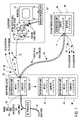
- FIG. 1is a block diagram illustrating a wideband signal distribution system used in a display environment
- FIG. 1Ais a block diagram illustrating a wideband distribution system configuration
- FIG. 2is a block diagram illustrating a local RF receiver/baseband out intelligent device system for use in sending baseband information to a wideband signal distribution system and receiving digital and non-digital information from the wideband signal distribution system;
- FIG. 3is a block diagram illustrating a typical BUD unit
- FIG. 4is a block diagram illustrating an intelligent device system for the remote sending of digital information using RF modulation
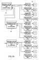
- FIG. 5is a block diagram illustrating an intelligent device system for use in local sending of digital information and receiving of digital and non-digital information using RF modulation;
- FIG. 6is a block diagram illustrating an intelligent device system including wireless capability
- FIG. 7is a block diagram illustrating a send and receive intelligent device system including wireless transmission.
- FIG. 8is a block diagram illustrating a remote send intelligent digital system including wireless capability.
- Digital transmission systemsincluding digital networks such as direct broadcast satellite, cellular telephone, personal communications service, wireless cable, cellular wireless cable, paging and wireless local loop, often employ analog waveforms, such as RF carrier waveforms, as a physical-layer transport mechanism for the baseband, i.e. the information carrying, waveform, as is known in the art.
- analog waveformssuch as RF carrier waveforms
- the baseband waveformis super-imposed on a higher-energy waveform to thereby allow for travelling of the baseband information over greater distances than would otherwise be possible with the baseband information alone.
- cable TV, broadcast TV, analog cellular, analog paging and AM/FM radiohave comprised analog signals that traveled on modulated RF carriers, which modulated signals have comprised, for example, signals in the frequency range of 5 MHz to several GHz. Additionally, traditional local analog signals have been carried on twisted-pair wires in simple baseband form, without a modulated carrier.
- Digital baseband signalsare sent over analog transmission channels, as is known in the art.
- Digital carrierssuch as T-1 lines, are examples of digital transmission channels for digital baseband signals.
- Digital baseband signalsare comprised of digitized bitstreams, which bitstreams may be formed by a sampling, such as by PCM, of, for example, a voice signal, as is known in the art.
- PCMdigital signal processing
- digital signalsare generally sent over digital transmission channels.
- modulation carrierssuch as in digital PCS and cellular telephone, DBS (direct broadcast satellite), wireless cable and cellular wireless cable, or hybrid fiber coax, for example.
- PCMis an example of binary coding, a simple coding method to form a baseband digital signal in which one bit, transmitted in one second, requires one Hertz of bandwidth.
- More complex coding methodsknown as “multilevel coding”, such as quadrature amplitude modulation (QAM) or vestigial sideband (VSB), are capable of greater bandwidth efficiency than PCM.
- QAMquadrature amplitude modulation
- VSBvestigial sideband
- the more complex the coding techniquethe higher the requirements for signal-to-noise ratio of the transmission channel, and, consequently, complicated techniques such as QAM could not historically be carried directly by available analog transmission techniques, such as category 5 or higher 568 wiring systems, without exceeding the FCC emission limits and therefore resulting in degradation of the data.
- Wideband signal distribution systemshave addressed the transmission of analog data, on a carrier within a specified frequency range, using a standard wiring system such as EIA/TIA 568, with minimal signal degradation, but have not addressed the transmission of digital data on a carrier on those media
- a signalmay be modulated, as discussed hereinabove, before it is transmitted.
- Any single modulation carrierat any set frequency, can have 360 different phases, each offset by one degree.
- Digital modulation systemssuch as quadrature amplitude modulation (QAM), take advantage of this to insert digital data at defined points as the RF carrier moves through a single oscillation cycle.
- Digital informationcan be sent on an RF analog carrier using the present invention.
- FIG. 1is a block diagram illustrating a wideband signal distribution system 10 used in a display environment 20 .
- the distribution system 10distributes signals within a specified frequency range, such as 5 MHz in excess of 1 GHz.
- the system of FIG. 1can be utilized for distributing any wideband signals, which wideband signals may be any digital or analog signal, or any RF carrier signal between 5 MHz to in excess of 1 GHz, for example.
- the typical display environment 20 for the wideband signal distribution networkincludes a display 22 and a source of signals 24 , such as a VCR or cable or digital cable TV, which source may be remotely located.
- a twisted pair wire cable 32is connected to input and output ports of a BUD 38 situated in, for example, wiring closet 40 , and carries thereon the output to the monitor 22 and the input from the source 24 .
- the BUDis discussed further hereinbelow with respect to FIG. 3 .
- “BUD”is defined as any type of unit or components for the distribution of wideband signals.
- the BUD 38is connected to additional display environments 20 a via the twisted pair wire cables 42 , 44 and is cascaded to another distribution unit 46 in a second wiring closet 48 by either coaxial cables or fiber optic cables 50 connected to the distribution unit 38 through impedance matching devices 51 . It will be understood that twisted pair wire cable could be utilized depending upon the distance between the wiring closets 40 , 48 . Further, the BUD 38 may be cascaded to the distribution units 52 , 54 within the same wiring closet 40 .
- FIG. 2illustrates a local RF receiver/baseband out intelligent device system 200 for use in receiving digital and analog information on an RF carrier, which carrier may be, for example, between 5 MHz to in excess of 1 GHz, from a wideband signal distribution system, and for use in sending baseband digital information to a wideband signal distribution system 10 , such as the wideband distribution system of FIG. 1 .
- an RF carrierwhich carrier may be, for example, between 5 MHz to in excess of 1 GHz
- a wideband signal distribution system 10such as the wideband distribution system of FIG. 1 .
- the local RF receiver/baseband out intelligent device system 200includes at least one addressable device 202 , and an intelligent device 204 that includes input 206 and output 208 baluns, and, if necessary, at least one digital combiner 212 , an RF splitter 214 , at least two RF band pass filters 216 , 218 , at least one demodulator 220 , a tone detect RF level control circuit 226 , a DSP 230 , an RF Channel detector 239 and a standard outlet 232 , which, as defined herein, includes, but is not limited to, a standard RF television/computer outlet.
- Each intelligent device system 200 , 400 , 500 , 600 , 700 and 800 of the present invention, in FIGS. 2 , 4 , 5 , 6 , 7 and 8offers the advantage that a high amount of throughput can be achieved in the transmission of digital and/or analog information on an RF, for example, 5 MHz to in excess of 1 GHz, carrier.
- the wideband signal distribution system 10may allow for distribution of, for example, 29 channels, wherein each channel is 6 MHz in width, and it is known that such channels can handle analog video signals.
- each 6 MHz channelcan handle, depending on the modulation technique used, in excess of 40 megabits per second of digital information, and new modulation techniques may increase this information to, and in excess of, 100 megabits per second.
- This 40 megabits per second transmissionallows for the transmission rate in excess of one gigabit/sec of digital information to be carried on the sum of the 29 RF channels in the wideband signal distribution system 10 .
- Using advanced modulation techniqueswill allow the wideband signal distribution system 10 to be expanded up to 60, or more, channels, thereby further increasing throughput data rate.
- the wideband signal distribution system 10functions as a passive infrastructure to distribute wideband signals modulated onto RF carriers within a specified frequency band among a plurality of outlets 20 , which outlets may be to and/or from outlets, such as the plurality of intelligent devices 204 , 404 , 504 , 604 , 704 and 804 as used in the intelligent device systems 200 , 400 , 500 , 600 , 700 and 800 of FIGS. 2 , 4 , 5 , 6 , 7 and 8 .
- widebandis defined as a signal or signal sets having an analog or digital characteristic that can be distributed on a carrier of 5 MHz to in excess of 1 GHz, for example.
- a wideband signal distribution system 10as shown in FIG.
- the wideband signal distribution system 10preferably includes at least one broadband uniform distribution (BUD) unit 38 , at least one modulator and channelizer (MAC) 39 , at least one breakout box (BOB) 41 , wiring, such as twisted pair or fiber, and coaxial cable, in order to effectuate connections.
- BODbroadband uniform distribution
- MACmodulator and channelizer
- BOBbreakout box
- wiringsuch as twisted pair or fiber, and coaxial cable
- a typical BUD unit 38is illustrated in FIG. 3 .
- Each BUD unit 38 , 46 , 52 , 54such as those shown in FIG. 1 , preferably has eight input ports and eight output ports. If there are only eight outlets in the system, then a single distribution unit 38 can accommodate all the outlets. However, for more than eight outlets, at least one more distribution unit cascaded to a distribution unit 38 is required. In this situation, the distribution unit 38 is considered to be a “master” unit and the additional distribution unit is considered to be a “slave” unit, as discussed further hereinbelow.
- An attribute of the distribution unitsis that the units are preferably identical and automatically configure themselves to operate either in the master mode or in the slave mode.
- the distribution unit 38utilizing twisted pair wire cable, includes eight input ports 62 - 1 , 62 - 2 , 62 - 3 , 624 , 62 - 5 , 62 - 6 , 62 - 7 , 62 - 8 and eight output ports 64 - 1 , 64 - 2 , 64 - 3 , 64 - 4 , 64 - 5 , 64 - 6 , 64 - 7 , 64 - 8 .
- Each of the ports 62 , 64is adapted for connection to the two wires of a respective twisted pair 66 , 68 . Additionally, FIG.
- FIG. 3illustrates the master/slave switch as having three parts 90 , 92 , 94 , with all of the switch parts being shown in the “slave” position.
- the default state of the master/slave switchis to its master position, so that the amplifier output 80 is coupled through the switch part 90 a transmission path 95 including the equalizer 96 , which connects the amplifier output 80 to the splitter input 82 , through the switch parts 90 , 94 .
- the switch part 92couples the output of the oscillator circuit 98 to the transmission path 95 through the directional coupler 100 .
- Each BUD 38preferably includes cascade in 102 and cascade out ports, and gain and equalization control 112 to provide proper gain or attenuation of signals within the system. Additionally, the BUD preferably includes a combiner 72 for applying signals appearing at all of the input ports to the transmission path, and a splitter 84 for applying signals appearing at the transmission path to all of the output ports. When the BUD is switched to “master state”, it couples the transmission path to the combiner 72 and the splitter 84 . When the BUD 38 is switched to “slave state”, it couples the combiner 72 to the signal outlet instead of to the transmission path and couples the splitter 84 to the signal inlet instead of to the transmission path.
- “Master state” and “slave state” switchingmay be done automatically through the use of a tone system.
- a secondary BUD 38When a secondary BUD 38 is added to a system, it preferably senses a tone produced by the “master” BUD and automatically switches to “slave state”.
- the BUDs 38are substantially identical and automatically configure themselves to operate when connected to the system.
- At least one BUD unitis connected to the intelligent device 204 of the intelligent device system 200 of FIG. 2 , and each BUD unit 38 of the present invention also includes wiring to at least two pin pairs, such as pins 3 , 4 and 7 , 8 , to thereby mirror the pins to and from the addressable device 202 of FIG. 2 .
- the local RF receiver/baseband out intelligent device system 200includes an addressable device 202 , preferably includes at least two twisted pair of cables 240 , or coaxial cables, for example, which cabling 240 is shown as connected to pins 3 , 4 and pins 7 , 8 , for example, and which cabling 240 passes to and from the addressable device 202 to the intelligent device 204 of the intelligent device system 200 .
- the addressable device 202may be, for example, an Ethernet card, or a NIC card, in a computer, or may be a display device that displays digital information, such as a digital television.
- the addressable device 202preferably has an address, such as an IP address, assigned thereto, to allow communications directed to that particular address to be delivered thereto.
- the twisted cable pair 240 from the addressable device 202is preferably passed within the intelligent device 204 to at least one balun 206 , which balun 206 performs impedance matching, such as to match a balanced twisted pair system 240 to a single ended system.
- the balun 206may be any device known to those skilled in the art used to perform impedance matching in RF applications.
- the two pair of twisted pair cablemay be, for example, unshielded twisted pair cable, or may be devices known in the art capable of replacing twisted pair cable, such as optical fiber or coaxial cable.
- the intelligent device 204receives the modulated RF signal, which may include IP and non-IP signal portions thereon, via the RF system input.
- the intelligent devicealso receives at least one incoming digital signal, such as a digital IP signal, from pins 3 , 4 of the addressable device.
- the RF system inputmay be, for example, connected to the at least one BUD 38 , on pins 7 , 8 , as mentioned hereinabove, after the BUD 38 has received the incoming digital signal from pins 3 , 4 .
- the modulated RF signalis, upon receipt at the intelligent device from the BUD 238 , preferably split into an IP portion of the incoming signal, and into a non-IP portion of the signal.
- the signal entering the intelligent deviceis preferably split by at least one RF splitter 214 , and is then differentiated according to the information frequency on the incoming carrier.
- the non-IP portion, digital or analog, of the signalmay be passed through a first band pass filter 216 that passes only the band of the RF carrier that includes the non-IP portion, and is preferably then fed to a standard RF television/computer outlet 232 . Only pre-selected RF channels, as discussed hereinabove, are allowed to pass to this standard outlet 232 .
- These non-IP RF channel signalsmay pass through a tone detector with an RF level control circuit 226 , in order to insure that a high quality picture signal is received at the television, monitor, or PC.
- the tone detector with RF level control circuit 226conditions the output RF signal to the standard RF TV/computer outlet 232 so as to not be over or under the specifications for high picture quality.
- the IP portion of the modulated RF signalis fed through a second bandpass filter 218 that passes a band outside the band passed by the first bandpass filter 216 , and the IP portion modulated RF signal is then demodulated by a demodulator 220 .
- the bandpass filters 216 , 218may be electronically controlled by the DSP 230 .
- the demodulator 220strips the RF carrier signal from the digital baseband signal, as is known in the art.
- the IP digital signalsare combined by a digital combiner 212 , such as a multiplexer, if necessary, in order to effectuate a parallel to serial conversion.
- the output of the digital combiner 212is a high speed serial digital output.
- the output of the digital combiner 230is routed to at least one addressable device 202 via the output cable pair, such as pins 7 and 8 , and may be so routed via a balun 208 , if necessary, for impedance matching.
- the digital informationis thereby provided to the addressable device 202 .
- the DSP 230(digital signal processor) of FIG. 2 is a DSP 230 as is known in the art.
- the DSP 230preferably controls RF channel detection and the at least one demodulator 220 . Additionally, in a preferred embodiment, the DSP 230 controls the bandpass filters 216 , 218 .
- FIG. 4illustrates an intelligent device system 400 for the remote sending of digital transmissions using modulated RF.
- the remote send-only intelligent device system 400includes, external to the intelligent device 402 , a plurality of incoming signals, such as from a desktop unit or desktop video feed, which signal is at least, in part, IP data, but which may include non-IP data, a BUD 238 , and a remote send intelligent device 402 that may include a digital combiner 410 , a traffic sensor 412 , at least one modulator 414 , an RF converter section 418 , a DSP 420 , an RF system channel detector 422 , and, if necessary, input/output baluns 430 or other impedance matching hardware.
- the digital signalmay be incoming to an input port of a BUD.
- This signalmay exit, for example, an output port of a BUD, in a twisted pair output, for example, such as on pins 3 and 4 , and may then be passed to the remote send intelligent device 402 .
- the signalmay be passed through a balun 430 , as discussed hereinabove, and is then preferably fed to a digital combiner 410 , such as a multiplexer.
- a digital combiner 410such as a multiplexer.
- each signal fed to the digital combiner 410may be, for example, ten megabits per second, and numerous signals from numerous output ports of the BUD 238 may be combined as specified according to the type of digital combiner 410 used. For example, in an embodiment wherein eight ten megabit per second channels enter an 8 way multiplexer, the signal exiting the digital combiner 410 would exit at eighty megabits per second.
- the signal exiting the digital combiner 410is sent to a modulator bank 414 including at least one modulator, and the signal entering the modulator bank 414 is preferably measured via a traffic sensor 412 to determine if the information volume is greater than the normal capacity of, for example, a single modulator. If the volume is greater, the DSP 420 will, in turn, direct the incoming data to as many modulators as necessary to modulate all data from the combiner 410 .
- the traffic sensor 412may additionally feed information to, or receive information from, the DSP 420 , in order to effectuate the decision of the modulators to be used.
- the DSP 420is discussed further hereinbelow.
- the at least one modulator 414 communicatively connected to the traffic sensor 412conditions the signal to a modulated digital signal via methods known to those skilled in the art, such as QAM modulation.
- the output of the modulator 414is then modulated to a set carrier channel frequency by an RF converter section 418 , which RF converter section 418 may consist of, for example, oscillators, amplifiers, combiners, channel selectors, and channel width adjustors.
- the digital signal processor (DSP) 420is a DSP as is known in the art, and determines the number of modulators, or the channel width or widths, needed to modulate the signal incoming to the traffic sensor 412 , as well as the number of RF channels, and which RF channels, on which the output of the modulator or modulators is modulated. Note that, for example, where QAM modulation is used, QAM modulation is generally 40 megabits per second, per 6 MHz RF channel, thus requiring the use of two 6 MHz RF channels in order to modulate the 80 megabits per second coming from the digital combiner in the exemplary embodiment hereinabove.
- the RF channel frequencyis selected from at least two available frequency channels.
- the channel widthcan, for example, be increased from 6 MHz per channel to 12 MHz per channel in order to accommodate, for example, the 80 megabits per second digital stream, if adjacent channel space is available or unused.
- the DSP 420is updated as to the channels that are currently in use by the wideband signal distribution system, thereby indicating the channels and bandwidth that are currently available for use by the system.
- the DSP 240may additionally place a guardband between channels, or perform other signal conditioning functions, and may be the same DSP, or a different DSP, than that in FIGS. 2 , 4 , 5 , 6 , 7 or 8 .
- FIG. 5is a block diagram illustrating an intelligent device system 500 for use in local sending and receiving in the generation of at least one digital signal on a modulated RF signal.
- the local send and receive intelligent device system 500includes certain of the devices of FIGS. 2 and 4 .
- the system of FIG. 5preferably includes a plurality of addressable devices 202 , such as Ethernet or NIC cards, or digital display devices, as discussed hereinabove with respect to FIG. 2 , which addressable devices 202 are preferably located at, for example, a desktop location.
- addressable devices 202are preferably located at, for example, a desktop location.
- two unused pin pairssuch as pins 1 , 2 and 7 , 8 , are used to send and receive signals between the addressable device 202 and the intelligent device 502 .
- an intelligent device 502such as the local send and receive intelligent device 502 , and may pass within the intelligent device 502 to at least one balun 504 , for impedance matching.
- the signals incoming from each of the addressable devices 202are combined by a digital combiner 410 , and passed through a traffic sensor 412 , at least one modulator 414 , and an RF converter section 418 .
- the traffic sensor 412 , at least one modulator 414 , and RF converter section 418may be controlled by, or be in communication with, a DSP 420 , substantially as discussed hereinabove with respect to FIG. 4 .
- an RF system channel detectoris preferably in communication with the DSP 420 in order to update the DSP 420 as to the RF channels in use and available.
- the output of the RF converter section 418is preferably impedance matched to a BUD 38 , and feeds the signal exiting the RF converter section 418 to the BUD input port or ports.
- the BUD output port or portsthen feed an RF splitter 214 , which splits the signal entering the intelligent device 502 , and the signal is then differentiated according to the information frequency on the incoming carrier.
- the RF splitter 214sends the information of the RF channels in use to the RF system channel detector 239 .
- the modulated RF signalis preferably differentiated into an IP portion, i.e. a digital data portion, of the incoming signal, and into a non-IP portion of the signal, according to the information frequency on the incoming carrier.
- the bandpass filtersmay be electronically controlled by the DSP 420 .
- the non-IP portion, digital/analog, of the signalis passed through a bandpass filter 216 and is preferably then fed to a standard RF television/computer outlet 232 .
- the non-IP RF channel signalsmay pass through a tone detector with an RF level control circuit 226 , in order to insure that a high quality picture signal is received at the television/computer 232 .
- the tone detector with RF level control circuitsituates the output RF signal to the standard RF television/computer outlet to not be over or under the limitations for proper picture display.
- the IP portion of the modulated RF signalis fed through a second bandpass filter 218 that passes a band outside the band passed by the first bandpass filter 216 , and the IP portion is then demodulated by at least one demodulator 220 .
- the demodulator 220strips the RF carrier signal from the digital baseband signal, as is known in the art.
- the digital signalsmay be combined by a digital combiner 212 , such as a multiplexer, in order to effectuate a parallel to serial conversion.
- the output of the digital combiner 212is a high speed serial digital output, on the order of, for example, up to, or in excess of, several Gbit/sec.
- the output of the digital combiner 212is then preferably routed to a splitter, which splitter feeds an outgoing signal to the input pin pairs, such as pins 7 and 8 , of at least one addressable device 202 .
- the input cable pair to the addressable device 202such as pins 7 and 8 , may be routed via a balun, if necessary, for impedance matching.
- FIG. 6is a block diagram illustrating an intelligent device system including wireless transmission 600 .
- the intelligent device system of FIG. 6operates substantially in accordance with FIG. 2 discussed hereinabove, for example, and additionally includes a transcoder 602 for sending transmissions from the RF splitter 214 to the wireless port 604 , and a wireless demodulator 606 for receiving transmissions from the wireless port 604 and sending those received wireless transmissions to the digital combiner 212 for entry to the BUD 38 .
- the RF splitter 214sends the signal to a third bandpass filter 610 that passes only the RF channels having wireless information thereon, and the transcoder 602 converts the modulation scheme from, for example, QAM to QPSK, and also up converts the frequency to allow transmission via the wireless port 604 .
- the wireless port 604may include, for example, a wireless antenna.
- FIG. 7is a block diagram illustrating a send and receive intelligent device system 700 including wireless transmission.
- the intelligent device system 700 of FIG. 7operates substantially in accordance with the system of FIG. 5 , for example, and additionally includes a transcoder 702 for sending transmissions from the RF splitter 214 to the wireless port 704 , and a wireless demodulator 706 for receiving transmissions from the wireless port 704 and sending those received wireless transmissions to the digital combiner 410 .
- the RF splitter 214sends the signal to a third bandpass filter 710 that passes only the RF channels having wireless information thereon, and the transcoder 702 converts the modulation scheme from, for example, QAM to QPSK, and also up converts the frequency to allow transmission via the wireless port 704 .
- the wireless port 704may include, for example, a wireless antenna.
- FIG. 8is a block diagram illustrating an intelligent device system 800 including wireless transmission.
- the intelligent device system of FIG. 8operates substantially in accordance with FIG. 4 discussed hereinabove, for example, and additionally includes a transcoder 802 for sending transmissions from the RF splitter 804 to the wireless port 806 , and a wireless port 806 for sending those received wireless transmissions to the digital combiner 410 for entry to the BUD 38 .
- the RF splitter 804sends the signal to a first bandpass filter 810 that passes only the RF channels having wireless information thereon, a second bandpass filter 812 passes the non-wireless information, and the transcoder 802 converts the modulation scheme from, for example, QAM to QPSK, and also up converts the frequency to allow transmission via the wireless port 806 .
- the wireless port 806may include, for example, a wireless antenna.
- a demodulator 820demodulates wireless information for entry to the digital combiner 410 .
Landscapes
- Engineering & Computer Science (AREA)
- Signal Processing (AREA)
- Multimedia (AREA)
- Computer Networks & Wireless Communication (AREA)
- Computer Security & Cryptography (AREA)
- Databases & Information Systems (AREA)
- Two-Way Televisions, Distribution Of Moving Picture Or The Like (AREA)
Abstract
Description
Claims (12)
Priority Applications (10)
| Application Number | Priority Date | Filing Date | Title |
|---|---|---|---|
| US09/749,258US7346918B2 (en) | 2000-12-27 | 2000-12-27 | Intelligent device system and method for distribution of digital signals on a wideband signal distribution system |
| US09/824,531US20020083475A1 (en) | 2000-12-27 | 2001-04-02 | Intelligent device system and method for distribution of digital signals on a wideband signal distribution system |
| PCT/US2001/049629WO2002054766A1 (en) | 2000-12-27 | 2001-12-27 | An intelligent device system and method for distribution of digital signals on a wideband signal dfistribution system |
| US12/068,102US7941822B2 (en) | 2000-12-27 | 2008-02-01 | Intelligent device system and method for distribution of digital signals on a wideband signal distribution system |
| US12/564,663US8341679B2 (en) | 2000-12-27 | 2009-09-22 | Intelligent device system and method for distribution of digital signals on a wideband signal distribution system |
| US13/402,813US9015774B2 (en) | 2000-12-27 | 2012-02-22 | Intelligent device system and method for distribution of digital signals on a wideband signal distribution system |
| US13/682,222US8984565B2 (en) | 2000-12-27 | 2012-11-20 | Intelligent device system and method for distribution of digital signals on a wideband signal distribution system |
| US13/799,749US20130266050A1 (en) | 2000-12-27 | 2013-03-13 | Intelligent device system and method for distribution of digital signals on a wideband signal distribution system |
| US14/167,289US9363554B2 (en) | 2000-12-27 | 2014-01-29 | Intelligent device system and method for distribution of digital signals on a wideband signal distribution system |
| US14/679,678US10136180B2 (en) | 2000-12-27 | 2015-04-06 | Intelligent device system and method for distribution of digital signals on a wideband signal distribution system |
Applications Claiming Priority (1)
| Application Number | Priority Date | Filing Date | Title |
|---|---|---|---|
| US09/749,258US7346918B2 (en) | 2000-12-27 | 2000-12-27 | Intelligent device system and method for distribution of digital signals on a wideband signal distribution system |
Related Child Applications (2)
| Application Number | Title | Priority Date | Filing Date |
|---|---|---|---|
| US09/824,531Continuation-In-PartUS20020083475A1 (en) | 2000-12-27 | 2001-04-02 | Intelligent device system and method for distribution of digital signals on a wideband signal distribution system |
| US12/068,102DivisionUS7941822B2 (en) | 2000-12-27 | 2008-02-01 | Intelligent device system and method for distribution of digital signals on a wideband signal distribution system |
Publications (2)
| Publication Number | Publication Date |
|---|---|
| US20020083474A1 US20020083474A1 (en) | 2002-06-27 |
| US7346918B2true US7346918B2 (en) | 2008-03-18 |
Family
ID=25012974
Family Applications (8)
| Application Number | Title | Priority Date | Filing Date |
|---|---|---|---|
| US09/749,258Expired - LifetimeUS7346918B2 (en) | 2000-12-27 | 2000-12-27 | Intelligent device system and method for distribution of digital signals on a wideband signal distribution system |
| US12/068,102Expired - LifetimeUS7941822B2 (en) | 2000-12-27 | 2008-02-01 | Intelligent device system and method for distribution of digital signals on a wideband signal distribution system |
| US12/564,663Expired - Fee RelatedUS8341679B2 (en) | 2000-12-27 | 2009-09-22 | Intelligent device system and method for distribution of digital signals on a wideband signal distribution system |
| US13/402,813Expired - Fee RelatedUS9015774B2 (en) | 2000-12-27 | 2012-02-22 | Intelligent device system and method for distribution of digital signals on a wideband signal distribution system |
| US13/682,222Expired - Fee RelatedUS8984565B2 (en) | 2000-12-27 | 2012-11-20 | Intelligent device system and method for distribution of digital signals on a wideband signal distribution system |
| US13/799,749AbandonedUS20130266050A1 (en) | 2000-12-27 | 2013-03-13 | Intelligent device system and method for distribution of digital signals on a wideband signal distribution system |
| US14/167,289Expired - Fee RelatedUS9363554B2 (en) | 2000-12-27 | 2014-01-29 | Intelligent device system and method for distribution of digital signals on a wideband signal distribution system |
| US14/679,678Expired - Fee RelatedUS10136180B2 (en) | 2000-12-27 | 2015-04-06 | Intelligent device system and method for distribution of digital signals on a wideband signal distribution system |
Family Applications After (7)
| Application Number | Title | Priority Date | Filing Date |
|---|---|---|---|
| US12/068,102Expired - LifetimeUS7941822B2 (en) | 2000-12-27 | 2008-02-01 | Intelligent device system and method for distribution of digital signals on a wideband signal distribution system |
| US12/564,663Expired - Fee RelatedUS8341679B2 (en) | 2000-12-27 | 2009-09-22 | Intelligent device system and method for distribution of digital signals on a wideband signal distribution system |
| US13/402,813Expired - Fee RelatedUS9015774B2 (en) | 2000-12-27 | 2012-02-22 | Intelligent device system and method for distribution of digital signals on a wideband signal distribution system |
| US13/682,222Expired - Fee RelatedUS8984565B2 (en) | 2000-12-27 | 2012-11-20 | Intelligent device system and method for distribution of digital signals on a wideband signal distribution system |
| US13/799,749AbandonedUS20130266050A1 (en) | 2000-12-27 | 2013-03-13 | Intelligent device system and method for distribution of digital signals on a wideband signal distribution system |
| US14/167,289Expired - Fee RelatedUS9363554B2 (en) | 2000-12-27 | 2014-01-29 | Intelligent device system and method for distribution of digital signals on a wideband signal distribution system |
| US14/679,678Expired - Fee RelatedUS10136180B2 (en) | 2000-12-27 | 2015-04-06 | Intelligent device system and method for distribution of digital signals on a wideband signal distribution system |
Country Status (2)
| Country | Link |
|---|---|
| US (8) | US7346918B2 (en) |
| WO (1) | WO2002054766A1 (en) |
Cited By (36)
| Publication number | Priority date | Publication date | Assignee | Title |
|---|---|---|---|---|
| US20050071423A1 (en)* | 2003-09-26 | 2005-03-31 | Jaakko Rajaniemi | System, apparatus, and method for providing Web services on mobile devices |
| US20050071419A1 (en)* | 2003-09-26 | 2005-03-31 | Lewontin Stephen Paul | System, apparatus, and method for providing Web services using wireless push |
| US20050100043A1 (en)* | 2000-04-19 | 2005-05-12 | Serconet Ltd | Network combining wired and non-wired segments |
| US20070176676A1 (en)* | 2003-09-01 | 2007-08-02 | Secretary Of State Of Defence | Modulation signals for a satellite navigation system |
| US20090031391A1 (en)* | 2007-03-08 | 2009-01-29 | Emerson Network Power Connectivity Solutions | Electronically controlled catv system |
| US20090067433A1 (en)* | 2007-09-12 | 2009-03-12 | The Directv Group, Inc. | Method and system for controlling a back-up network adapter in a local collection facility from a remote facility |
| US20090067365A1 (en)* | 2007-09-11 | 2009-03-12 | The Directv Group, Inc. | Method and System for Switching to an Engineering Signal Processing System from a Production Signal Processing System |
| US20090066848A1 (en)* | 2007-09-12 | 2009-03-12 | The Directv Group, Inc. | Method and system for controlling a back-up receiver and encoder in a local collection facility from a remote facility |
| US20090070838A1 (en)* | 2007-09-11 | 2009-03-12 | The Directv Group, Inc. | Method and system for communicating between a local collection facility and a remote facility |
| US20090070823A1 (en)* | 2007-09-11 | 2009-03-12 | The Directv Group, Inc. | Method and System for Monitoring and Switching Between a Primary and Diverse Site in a Satellite Communication System |
| US20090070846A1 (en)* | 2007-09-12 | 2009-03-12 | The Directv Group, Inc. | Method and system for monitoring and controlling a local collection facility from a remote facility using an asynchronous transfer mode (atm) network |
| US20090070824A1 (en)* | 2007-09-11 | 2009-03-12 | The Directv Group, Inc. | Method and System for Monitoring and Switching Between Primary and Back-up Uplink Signal Processing Circuits in a Satellite Communication System |
| US20090070825A1 (en)* | 2007-09-11 | 2009-03-12 | The Directv Group, Inc. | Method and System for Monitoring and Controlling Receiving Circuit Modules at a Local Collection Facility From a Remote Facility |
| US20090113490A1 (en)* | 2007-10-30 | 2009-04-30 | Wasden Mitchell B | Method and system for monitoring and controlling a local collection facility from a remote facility through an ip network |
| US20090109836A1 (en)* | 2007-10-31 | 2009-04-30 | Wasden Mitchell B | Method and system for controlling redundancy of individual components of a remote facility system |
| US20090109883A1 (en)* | 2007-10-31 | 2009-04-30 | Wasden Mitchell B | Method and system for monitoring and encoding signals in a local facility and communicating the signals between a local collection facility and a remote facility using an ip network |
| US7596350B1 (en) | 2006-09-29 | 2009-09-29 | The Directv Group, Inc. | Method and system for determining delays between a primary site and diverse site in a satellite communication system |
| US20090285334A1 (en)* | 2003-09-12 | 2009-11-19 | Neil Birkett | Method for amplitude insensitive packet detection |
| US20100079220A1 (en)* | 2008-09-30 | 2010-04-01 | Trott Keith D | N-Channel Multiplexer |
| US7693483B1 (en) | 2006-09-29 | 2010-04-06 | The Directv Group, Inc. | Method and system for operating a satellite communication system with regional redundant sites and a central site |
| US7706747B1 (en) | 2006-09-29 | 2010-04-27 | The Directv Group, Inc. | Method and system for broadcasting in a satellite communication system when switching between a primary site and a diverse site |
| US7783248B1 (en)* | 2006-09-29 | 2010-08-24 | The Directv Group, Inc. | Method and apparatus for connecting primary and diverse sites in a satellite communication system |
| US8170069B2 (en) | 2007-09-11 | 2012-05-01 | The Directv Group, Inc. | Method and system for processing signals from a local collection facility at a signal processing facility |
| US20120216231A1 (en)* | 2000-12-27 | 2012-08-23 | Z-Band, Inc. | Intelligent device system and method for distribution of digital signals on a wideband signal distribution system |
| US8781039B2 (en) | 2012-10-26 | 2014-07-15 | Deere & Company | Receiver and method for receiving a composite signal |
| US8942157B2 (en) | 2012-10-26 | 2015-01-27 | Deere & Company | Receiver and method for receiving a composite signal |
| US8942264B2 (en) | 2012-10-26 | 2015-01-27 | Deere & Company | Receiver and method for receiving a composite signal |
| US8973058B2 (en) | 2007-09-11 | 2015-03-03 | The Directv Group, Inc. | Method and system for monitoring and simultaneously displaying a plurality of signal channels in a communication system |
| US8988986B2 (en) | 2007-09-12 | 2015-03-24 | The Directv Group, Inc. | Method and system for controlling a back-up multiplexer in a local collection facility from a remote facility |
| US9048964B2 (en) | 2012-10-26 | 2015-06-02 | Deere & Company | Receiver and method for receiving a composite signal |
| US9049354B2 (en)* | 2007-10-30 | 2015-06-02 | The Directv Group, Inc. | Method and system for monitoring and controlling a back-up receiver in local collection facility from a remote facility using an IP network |
| US9300412B2 (en) | 2007-09-11 | 2016-03-29 | The Directv Group, Inc. | Method and system for operating a receiving circuit for multiple types of input channel signals |
| US9313457B2 (en) | 2007-09-11 | 2016-04-12 | The Directv Group, Inc. | Method and system for monitoring a receiving circuit module and controlling switching to a back-up receiving circuit module at a local collection facility from a remote facility |
| US9762973B2 (en) | 2008-11-04 | 2017-09-12 | The Directv Group, Inc. | Method and system for operating a receiving circuit module to encode a channel signal into multiple encoding formats |
| US9831971B1 (en) | 2011-04-05 | 2017-11-28 | The Directv Group, Inc. | Method and system for operating a communication system encoded into multiple independently communicated encoding formats |
| US10986165B2 (en) | 2004-01-13 | 2021-04-20 | May Patents Ltd. | Information device |
Families Citing this family (19)
| Publication number | Priority date | Publication date | Assignee | Title |
|---|---|---|---|---|
| US7373414B2 (en)* | 2002-08-29 | 2008-05-13 | Amx Llc | Multi-media system and method for simultaneously delivering multi-media data to multiple destinations |
| JP2005175826A (en)* | 2003-12-10 | 2005-06-30 | Matsushita Electric Ind Co Ltd | Optical fiber radio transmission system, transmitter and receiver |
| US7818774B2 (en)* | 2006-03-24 | 2010-10-19 | Zenith Electronics Llc | Internet protocol conversion module for televisions |
| US9826197B2 (en) | 2007-01-12 | 2017-11-21 | Activevideo Networks, Inc. | Providing television broadcasts over a managed network and interactive content over an unmanaged network to a client device |
| US7804355B2 (en)* | 2007-01-19 | 2010-09-28 | Z-Band, Inc. | Managed wideband radio frequency distribution system with signal level enabling interface device |
| US8031482B2 (en)* | 2007-08-20 | 2011-10-04 | Ortronics, Inc. | Mounting assembly with video distribution functionality |
| US8335471B2 (en)* | 2008-12-11 | 2012-12-18 | CSR Technology, Inc. | Systems and methods for channel pairing a transmitter and a receiver |
| US20130343284A1 (en)* | 2010-09-29 | 2013-12-26 | Unication Group/Unication Co., LTD. | Method for members of emergency rescue group utilizing radios to transmit compound files containing compressed photo/text/voice data of an emergency event site directly or through signal repeater to console for reappearance of the event site |
| DE102011100212A1 (en)* | 2011-05-02 | 2012-11-08 | GM Global Technology Operations LLC (n. d. Gesetzen des Staates Delaware) | Transceiving apparatus and method for transmitting and receiving data |
| EP2815582B1 (en) | 2012-01-09 | 2019-09-04 | ActiveVideo Networks, Inc. | Rendering of an interactive lean-backward user interface on a television |
| US9800945B2 (en) | 2012-04-03 | 2017-10-24 | Activevideo Networks, Inc. | Class-based intelligent multiplexing over unmanaged networks |
| WO2014145921A1 (en) | 2013-03-15 | 2014-09-18 | Activevideo Networks, Inc. | A multiple-mode system and method for providing user selectable video content |
| US9442186B2 (en)* | 2013-05-13 | 2016-09-13 | Microsoft Technology Licensing, Llc | Interference reduction for TOF systems |
| EP3005712A1 (en) | 2013-06-06 | 2016-04-13 | ActiveVideo Networks, Inc. | Overlay rendering of user interface onto source video |
| US8811459B1 (en)* | 2013-10-21 | 2014-08-19 | Oleumtech Corporation | Robust and simple to configure cable-replacement system |
| US9788029B2 (en)* | 2014-04-25 | 2017-10-10 | Activevideo Networks, Inc. | Intelligent multiplexing using class-based, multi-dimensioned decision logic for managed networks |
| US10462452B2 (en) | 2016-03-16 | 2019-10-29 | Microsoft Technology Licensing, Llc | Synchronizing active illumination cameras |
| CN107086927B (en)* | 2016-04-06 | 2021-03-23 | 腾讯科技(深圳)有限公司 | User audio and video authority management method, device and system |
| US10574424B2 (en)* | 2016-08-31 | 2020-02-25 | Avago Technologies International Sales Pte. Limited | Transmission bandwidth improvements for DVB-S2X channel bonding |
Citations (31)
| Publication number | Priority date | Publication date | Assignee | Title |
|---|---|---|---|---|
| US5347304A (en)* | 1991-09-10 | 1994-09-13 | Hybrid Networks, Inc. | Remote link adapter for use in TV broadcast data transmission system |
| US5485630A (en) | 1994-03-31 | 1996-01-16 | Panasonic Technologies, Inc. | Audio/video distribution system |
| US5544161A (en) | 1995-03-28 | 1996-08-06 | Bell Atlantic Network Services, Inc. | ATM packet demultiplexer for use in full service network having distributed architecture |
| US5557319A (en)* | 1994-12-28 | 1996-09-17 | U.S. Philips Corporation | Subscriber return system for CATV full service networks |
| US5608446A (en)* | 1994-03-31 | 1997-03-04 | Lucent Technologies Inc. | Apparatus and method for combining high bandwidth and low bandwidth data transfer |
| US5708961A (en)* | 1995-05-01 | 1998-01-13 | Bell Atlantic Network Services, Inc. | Wireless on-premises video distribution using digital multiplexing |
| US5805806A (en) | 1995-12-18 | 1998-09-08 | Intel Corporation | Method and apparatus for providing interactive networking between televisions and personal computers |
| US5828403A (en) | 1995-12-22 | 1998-10-27 | U S West, Inc. | Method and system for selecting and receiving digitally transmitted signals at a plurality of television receivers |
| US5862451A (en)* | 1996-01-22 | 1999-01-19 | Motorola, Inc. | Channel quality management in a cable telephony system |
| US5886732A (en) | 1995-11-22 | 1999-03-23 | Samsung Information Systems America | Set-top electronics and network interface unit arrangement |
| US5901340A (en)* | 1995-06-28 | 1999-05-04 | The Whitaker Corporation | Wideband signal distribution system |
| US5946301A (en) | 1997-02-14 | 1999-08-31 | Fluke Corporation | Circuit for determining local area network speed |
| US5982741A (en) | 1998-09-17 | 1999-11-09 | Tut Systems, Inc. | Method and apparatus for automatically reducing cross-talk between wires coupled to a common network device |
| US5982411A (en) | 1996-12-18 | 1999-11-09 | General Instrument Corporation | Navigation among grouped television channels |
| US6008777A (en)* | 1997-03-07 | 1999-12-28 | Intel Corporation | Wireless connectivity between a personal computer and a television |
| US6021158A (en) | 1996-05-09 | 2000-02-01 | Texas Instruments Incorporated | Hybrid wireless wire-line network integration and management |
| US6041056A (en) | 1995-03-28 | 2000-03-21 | Bell Atlantic Network Services, Inc. | Full service network having distributed architecture |
| US6124878A (en)* | 1996-12-20 | 2000-09-26 | Time Warner Cable, A Division Of Time Warner Enterainment Company, L.P. | Optimum bandwidth utilization in a shared cable system data channel |
| US6208833B1 (en) | 1996-06-28 | 2001-03-27 | The Whitaker Corporation | Echo cancellation for a broadband distribution system |
| US6314110B1 (en)* | 1998-03-06 | 2001-11-06 | Cisco Technology, Inc. | Method and apparatus for distributed bandwidth allocation for a bi-directional ring media with spatial and local reuse |
| US6481013B1 (en)* | 1998-11-09 | 2002-11-12 | Peracom Networks, Inc. | Entertainment and computer coaxial network and method of distributing signals therethrough |
| US6493875B1 (en)* | 1997-02-19 | 2002-12-10 | Next Level Communications, Inc. | In-home wireless |
| US6526581B1 (en)* | 1999-08-03 | 2003-02-25 | Ucentric Holdings, Llc | Multi-service in-home network with an open interface |
| US6567981B1 (en)* | 1998-08-03 | 2003-05-20 | Elysium Broadband Inc. | Audio/video signal redistribution system |
| US20030128303A1 (en)* | 2002-01-04 | 2003-07-10 | Shigeto Masuda | Digital/analog common tuner |
| US6622304B1 (en)* | 1996-09-09 | 2003-09-16 | Thomas W. Carhart | Interface system for computing apparatus and communications stations |
| US6757909B1 (en)* | 1999-12-29 | 2004-06-29 | Sony Corporation | Internet set-top box having an in-band tuner and cable modem |
| US6796555B1 (en)* | 1999-07-19 | 2004-09-28 | Lucent Technologies Inc. | Centralized video controller for controlling distribution of video signals |
| US6915530B1 (en)* | 1994-11-30 | 2005-07-05 | General Instrument Corporation | Ingress detection and characterization by time/frequency map |
| US6941576B2 (en)* | 1999-04-12 | 2005-09-06 | Texas Instruments Incorporated | System and methods for home network communications |
| US7068682B2 (en)* | 2000-02-28 | 2006-06-27 | Qwest Communications International Inc. | Signal distribution within customer premises |
Family Cites Families (61)
| Publication number | Priority date | Publication date | Assignee | Title |
|---|---|---|---|---|
| US980359A (en) | 1910-11-05 | 1911-01-03 | George Owen Squier | Multiplex telephony and telegraphy. |
| US4901307A (en) | 1986-10-17 | 1990-02-13 | Qualcomm, Inc. | Spread spectrum multiple access communication system using satellite or terrestrial repeaters |
| US4870408A (en)* | 1987-04-30 | 1989-09-26 | Motorola, Inc. | Method for dynamically allocating data channels on a trunked communication system |
| US4831373A (en)* | 1987-04-30 | 1989-05-16 | Motorola, Inc. | Method for dynamically allocating data channels on a trunked communication system |
| US5103459B1 (en) | 1990-06-25 | 1999-07-06 | Qualcomm Inc | System and method for generating signal waveforms in a cdma cellular telephone system |
| US5511073A (en) | 1990-06-25 | 1996-04-23 | Qualcomm Incorporated | Method and apparatus for the formatting of data for transmission |
| CA2568984C (en) | 1991-06-11 | 2007-07-10 | Qualcomm Incorporated | Variable rate vocoder |
| JP3438918B2 (en) | 1992-11-27 | 2003-08-18 | コモンウェルス サイエンティフィック アンド インダストリアル リサーチ オーガニゼーション | Wireless LAN |
| KR960009474B1 (en)* | 1993-11-29 | 1996-07-19 | 양승택 | High speed traffic statistics processing device using memory |
| US6069621A (en)* | 1994-05-10 | 2000-05-30 | Schupak; Donald | Distributed computer system for providing audio, video, and information signals to plural modules throughout a home |
| US5491099A (en)* | 1994-08-29 | 1996-02-13 | United Microelectronics Corporation | Method of making silicided LDD with recess in semiconductor substrate |
| US5585850A (en)* | 1994-10-31 | 1996-12-17 | Schwaller; John | Adaptive distribution system for transmitting wideband video data over narrowband multichannel wireless communication system |
| US6292476B1 (en)* | 1997-04-16 | 2001-09-18 | Qualcomm Inc. | Method and apparatus for providing variable rate data in a communications system using non-orthogonal overflow channels |
| MY121893A (en)* | 1995-04-28 | 2006-03-31 | Qualcomm Inc | Method and apparatus for providing variable rate data in a communications system using statistical multiplexing. |
| JP3698273B2 (en)* | 1995-07-20 | 2005-09-21 | ソニー株式会社 | Electronic program guide transmission apparatus and method, electronic program guide reception apparatus and method, and electronic program guide transmission / reception system and method |
| US5875386A (en)* | 1996-01-30 | 1999-02-23 | The Whitaker Corporation | Enabling and cable simulating circuits for wideband signal distribution system |
| AU2588797A (en)* | 1996-03-29 | 1997-10-22 | Motorola, Inc. | Apparatus and method for spectrum management in a multipoint communication system |
| US5765097A (en)* | 1996-05-20 | 1998-06-09 | At & T Corp | Shared hybrid fiber-coax network having reduced ingress noise in the upstream channel transmitted via a repeater |
| US6088360A (en)* | 1996-05-31 | 2000-07-11 | Broadband Networks Corporation | Dynamic rate control technique for video multiplexer |
| US5859840A (en)* | 1996-05-31 | 1999-01-12 | Qualcomm Incorporated | Spread spectrum communication system which defines channel groups comprising selected channels that are additional to a primary channel and transmits group messages during call set up |
| US5818906A (en)* | 1996-07-02 | 1998-10-06 | Motorola Inc. | Connection event reporting in a cable telephony system |
| US6215821B1 (en)* | 1996-08-07 | 2001-04-10 | Lucent Technologies, Inc. | Communication system using an intersource coding technique |
| US5867483A (en)* | 1996-11-12 | 1999-02-02 | Visual Networks, Inc. | Method and apparatus for measurement of peak throughput in packetized data networks |
| US5970386A (en)* | 1997-01-27 | 1999-10-19 | Hughes Electronics Corporation | Transmodulated broadcast delivery system for use in multiple dwelling units |
| US6188436B1 (en)* | 1997-01-31 | 2001-02-13 | Hughes Electronics Corporation | Video broadcast system with video data shifting |
| US5963557A (en)* | 1997-04-11 | 1999-10-05 | Eng; John W. | High capacity reservation multiple access network with multiple shared unidirectional paths |
| US6075792A (en)* | 1997-06-16 | 2000-06-13 | Interdigital Technology Corporation | CDMA communication system which selectively allocates bandwidth upon demand |
| US6388999B1 (en)* | 1997-12-17 | 2002-05-14 | Tantivy Communications, Inc. | Dynamic bandwidth allocation for multiple access communications using buffer urgency factor |
| US6081536A (en) | 1997-06-20 | 2000-06-27 | Tantivy Communications, Inc. | Dynamic bandwidth allocation to transmit a wireless protocol across a code division multiple access (CDMA) radio link |
| US6181711B1 (en)* | 1997-06-26 | 2001-01-30 | Cisco Systems, Inc. | System and method for transporting a compressed video and data bit stream over a communication channel |
| US6028847A (en)* | 1997-07-31 | 2000-02-22 | Hewlett-Packard Company | Multiple stream traffic emulator |
| US6377981B1 (en) | 1997-11-20 | 2002-04-23 | Cyberstar, L.P. | Modular digital data communication cyberstation and cyberserver |
| JP3075251B2 (en)* | 1998-03-05 | 2000-08-14 | 日本電気株式会社 | Virtual Path Bandwidth Distribution System in Asynchronous Transfer Mode Switching Network |
| CA2237289C (en) | 1998-03-24 | 2006-07-11 | Vistar Telecommunications Inc. | Packet data communication system |
| US6546557B1 (en) | 1998-10-13 | 2003-04-08 | General Instrument Corporation | Method and system for enhancing digital video transmission to a set-top box |
| JP4178617B2 (en)* | 1998-10-14 | 2008-11-12 | 松下電器産業株式会社 | Optical transmission system, optical transmitter, and optical transmission method |
| US6147344A (en)* | 1998-10-15 | 2000-11-14 | Neogenesis, Inc | Method for identifying compounds in a chemical mixture |
| US6631118B1 (en)* | 1998-11-10 | 2003-10-07 | At&T Corp. | System and method for providing dynamic bandwidth on demand |
| US6598232B1 (en) | 1998-11-10 | 2003-07-22 | Nortel Networks Limited | Hybrid amplifier-regenerator for optimizing cable network transmissions |
| US6697376B1 (en)* | 1998-11-20 | 2004-02-24 | Diva Systems Corporation | Logical node identification in an information transmission network |
| US6452935B1 (en)* | 1998-11-25 | 2002-09-17 | Sony Corporation | Stream allocation in home networks |
| US6690938B1 (en)* | 1999-05-06 | 2004-02-10 | Qualcomm Incorporated | System and method for reducing dropped calls in a wireless communications network |
| US7017176B1 (en)* | 1999-06-10 | 2006-03-21 | Cisco Technology, Inc. | Data transmission over multiple upstream channels within a cable modem system |
| US6771614B1 (en) | 1999-07-06 | 2004-08-03 | Cisco Technology, Inc. | Wireless power control in conjunction with a wireline MAC protocol |
| JP3392077B2 (en) | 1999-08-05 | 2003-03-31 | シャープ株式会社 | Cable modem with wireless communication function |
| US6522865B1 (en) | 1999-08-10 | 2003-02-18 | David D. Otten | Hybrid satellite communications system |
| US6721957B1 (en)* | 1999-08-16 | 2004-04-13 | Georgia Tech Research Corporation | System and method for maximizing bandwidth efficiency in a digital video program stream |
| WO2001030003A1 (en) | 1999-10-22 | 2001-04-26 | Nextnet Wireless Inc. | Fixed ofdm wireless man utilizing cpe having internal antenna |
| US6519461B1 (en)* | 1999-10-29 | 2003-02-11 | Telefonaktiebolaget Lm Ericsson (Publ) | Channel-type switching from a common channel to a dedicated channel based on common channel load |
| US6678740B1 (en) | 2000-01-14 | 2004-01-13 | Terayon Communication Systems, Inc. | Process carried out by a gateway in a home network to receive video-on-demand and other requested programs and services |
| US20010030785A1 (en)* | 2000-02-23 | 2001-10-18 | Pangrac David M. | System and method for distributing information via a communication network |
| US6684247B1 (en)* | 2000-04-04 | 2004-01-27 | Telcordia Technologies, Inc. | Method and system for identifying congestion and anomalies in a network |
| US6647015B2 (en)* | 2000-05-22 | 2003-11-11 | Sarnoff Corporation | Method and apparatus for providing a broadband, wireless, communications network |
| US6912572B1 (en)* | 2000-06-20 | 2005-06-28 | Syscontrol Ag | Server monitoring |
| US6944406B1 (en)* | 2000-08-04 | 2005-09-13 | Fujitsu Limited | Transport system with tunable channel spacing DWDM |
| US6882799B1 (en)* | 2000-09-28 | 2005-04-19 | Nortel Networks Limited | Multi-grained network |
| US6785291B1 (en)* | 2000-09-29 | 2004-08-31 | Nortel Networks Limited | Apparatus and method for channel assignment of packet flows |
| US7346918B2 (en) | 2000-12-27 | 2008-03-18 | Z-Band, Inc. | Intelligent device system and method for distribution of digital signals on a wideband signal distribution system |
| CN100593332C (en)* | 2004-12-10 | 2010-03-03 | 美国博通公司 | Uplink Channel Bonding in CATV Communication System |
| US8699424B2 (en)* | 2008-06-27 | 2014-04-15 | Microsoft Corporation | Adapting channel width for improving the performance of wireless networks |
| US10129540B2 (en) | 2012-04-10 | 2018-11-13 | Texas Instruments Incorporated | Reduced complexity coefficient transmission for adaptive loop filtering (ALF) in video coding |
- 2000
- 2000-12-27USUS09/749,258patent/US7346918B2/ennot_activeExpired - Lifetime
- 2001
- 2001-12-27WOPCT/US2001/049629patent/WO2002054766A1/ennot_activeApplication Discontinuation
- 2008
- 2008-02-01USUS12/068,102patent/US7941822B2/ennot_activeExpired - Lifetime
- 2009
- 2009-09-22USUS12/564,663patent/US8341679B2/ennot_activeExpired - Fee Related
- 2012
- 2012-02-22USUS13/402,813patent/US9015774B2/ennot_activeExpired - Fee Related
- 2012-11-20USUS13/682,222patent/US8984565B2/ennot_activeExpired - Fee Related
- 2013
- 2013-03-13USUS13/799,749patent/US20130266050A1/ennot_activeAbandoned
- 2014
- 2014-01-29USUS14/167,289patent/US9363554B2/ennot_activeExpired - Fee Related
- 2015
- 2015-04-06USUS14/679,678patent/US10136180B2/ennot_activeExpired - Fee Related
Patent Citations (31)
| Publication number | Priority date | Publication date | Assignee | Title |
|---|---|---|---|---|
| US5347304A (en)* | 1991-09-10 | 1994-09-13 | Hybrid Networks, Inc. | Remote link adapter for use in TV broadcast data transmission system |
| US5608446A (en)* | 1994-03-31 | 1997-03-04 | Lucent Technologies Inc. | Apparatus and method for combining high bandwidth and low bandwidth data transfer |
| US5485630A (en) | 1994-03-31 | 1996-01-16 | Panasonic Technologies, Inc. | Audio/video distribution system |
| US6915530B1 (en)* | 1994-11-30 | 2005-07-05 | General Instrument Corporation | Ingress detection and characterization by time/frequency map |
| US5557319A (en)* | 1994-12-28 | 1996-09-17 | U.S. Philips Corporation | Subscriber return system for CATV full service networks |
| US5544161A (en) | 1995-03-28 | 1996-08-06 | Bell Atlantic Network Services, Inc. | ATM packet demultiplexer for use in full service network having distributed architecture |
| US6041056A (en) | 1995-03-28 | 2000-03-21 | Bell Atlantic Network Services, Inc. | Full service network having distributed architecture |
| US5708961A (en)* | 1995-05-01 | 1998-01-13 | Bell Atlantic Network Services, Inc. | Wireless on-premises video distribution using digital multiplexing |
| US5901340A (en)* | 1995-06-28 | 1999-05-04 | The Whitaker Corporation | Wideband signal distribution system |
| US5886732A (en) | 1995-11-22 | 1999-03-23 | Samsung Information Systems America | Set-top electronics and network interface unit arrangement |
| US5805806A (en) | 1995-12-18 | 1998-09-08 | Intel Corporation | Method and apparatus for providing interactive networking between televisions and personal computers |
| US5828403A (en) | 1995-12-22 | 1998-10-27 | U S West, Inc. | Method and system for selecting and receiving digitally transmitted signals at a plurality of television receivers |
| US5862451A (en)* | 1996-01-22 | 1999-01-19 | Motorola, Inc. | Channel quality management in a cable telephony system |
| US6021158A (en) | 1996-05-09 | 2000-02-01 | Texas Instruments Incorporated | Hybrid wireless wire-line network integration and management |
| US6208833B1 (en) | 1996-06-28 | 2001-03-27 | The Whitaker Corporation | Echo cancellation for a broadband distribution system |
| US6622304B1 (en)* | 1996-09-09 | 2003-09-16 | Thomas W. Carhart | Interface system for computing apparatus and communications stations |
| US5982411A (en) | 1996-12-18 | 1999-11-09 | General Instrument Corporation | Navigation among grouped television channels |
| US6124878A (en)* | 1996-12-20 | 2000-09-26 | Time Warner Cable, A Division Of Time Warner Enterainment Company, L.P. | Optimum bandwidth utilization in a shared cable system data channel |
| US5946301A (en) | 1997-02-14 | 1999-08-31 | Fluke Corporation | Circuit for determining local area network speed |
| US6493875B1 (en)* | 1997-02-19 | 2002-12-10 | Next Level Communications, Inc. | In-home wireless |
| US6008777A (en)* | 1997-03-07 | 1999-12-28 | Intel Corporation | Wireless connectivity between a personal computer and a television |
| US6314110B1 (en)* | 1998-03-06 | 2001-11-06 | Cisco Technology, Inc. | Method and apparatus for distributed bandwidth allocation for a bi-directional ring media with spatial and local reuse |
| US6567981B1 (en)* | 1998-08-03 | 2003-05-20 | Elysium Broadband Inc. | Audio/video signal redistribution system |
| US5982741A (en) | 1998-09-17 | 1999-11-09 | Tut Systems, Inc. | Method and apparatus for automatically reducing cross-talk between wires coupled to a common network device |
| US6481013B1 (en)* | 1998-11-09 | 2002-11-12 | Peracom Networks, Inc. | Entertainment and computer coaxial network and method of distributing signals therethrough |
| US6941576B2 (en)* | 1999-04-12 | 2005-09-06 | Texas Instruments Incorporated | System and methods for home network communications |
| US6796555B1 (en)* | 1999-07-19 | 2004-09-28 | Lucent Technologies Inc. | Centralized video controller for controlling distribution of video signals |
| US6526581B1 (en)* | 1999-08-03 | 2003-02-25 | Ucentric Holdings, Llc | Multi-service in-home network with an open interface |
| US6757909B1 (en)* | 1999-12-29 | 2004-06-29 | Sony Corporation | Internet set-top box having an in-band tuner and cable modem |
| US7068682B2 (en)* | 2000-02-28 | 2006-06-27 | Qwest Communications International Inc. | Signal distribution within customer premises |
| US20030128303A1 (en)* | 2002-01-04 | 2003-07-10 | Shigeto Masuda | Digital/analog common tuner |
Cited By (70)
| Publication number | Priority date | Publication date | Assignee | Title |
|---|---|---|---|---|
| US8848725B2 (en) | 2000-04-19 | 2014-09-30 | Conversant Intellectual Property Management Incorporated | Network combining wired and non-wired segments |
| US7633966B2 (en) | 2000-04-19 | 2009-12-15 | Mosaid Technologies Incorporated | Network combining wired and non-wired segments |
| US20050100043A1 (en)* | 2000-04-19 | 2005-05-12 | Serconet Ltd | Network combining wired and non-wired segments |
| US7876767B2 (en) | 2000-04-19 | 2011-01-25 | Mosaid Technologies Incorporated | Network combining wired and non-wired segments |
| US7715441B2 (en) | 2000-04-19 | 2010-05-11 | Mosaid Technologies Incorporated | Network combining wired and non-wired segments |
| US8289991B2 (en) | 2000-04-19 | 2012-10-16 | Mosaid Technologies Incorporated | Network combining wired and non-wired segments |
| US7933297B2 (en) | 2000-04-19 | 2011-04-26 | Mosaid Technologies Incorporated | Network combining wired and non-wired segments |
| US7636373B2 (en) | 2000-04-19 | 2009-12-22 | Mosaid Technologies Incorporated | Network combining wired and non-wired segments |
| US8867506B2 (en) | 2000-04-19 | 2014-10-21 | Conversant Intellectual Property Management Incorporated | Network combining wired and non-wired segments |
| US8873575B2 (en) | 2000-04-19 | 2014-10-28 | Conversant Intellectual Property Management Incorporated | Network combining wired and non-wired segments |
| US8873586B2 (en) | 2000-04-19 | 2014-10-28 | Conversant Intellectual Property Management Incorporated | Network combining wired and non-wired segments |
| US8982903B2 (en) | 2000-04-19 | 2015-03-17 | Conversant Intellectual Property Management Inc. | Network combining wired and non-wired segments |
| US8982904B2 (en) | 2000-04-19 | 2015-03-17 | Conversant Intellectual Property Management Inc. | Network combining wired and non-wired segments |
| US9015774B2 (en)* | 2000-12-27 | 2015-04-21 | Earl Hennenhoefer | Intelligent device system and method for distribution of digital signals on a wideband signal distribution system |
| US20120216231A1 (en)* | 2000-12-27 | 2012-08-23 | Z-Band, Inc. | Intelligent device system and method for distribution of digital signals on a wideband signal distribution system |
| US10136180B2 (en) | 2000-12-27 | 2018-11-20 | Chanbond Llc | Intelligent device system and method for distribution of digital signals on a wideband signal distribution system |
| US20130266050A1 (en)* | 2000-12-27 | 2013-10-10 | Z-Band, Inc. | Intelligent device system and method for distribution of digital signals on a wideband signal distribution system |
| US8976891B2 (en) | 2003-09-01 | 2015-03-10 | Secretary Of State For Defence | Modulation signals for a satellite navigation system |
| US8989301B2 (en) | 2003-09-01 | 2015-03-24 | Secretary Of State For Defence | Modulation signals for a satellite navigation system |
| US20110051781A1 (en)* | 2003-09-01 | 2011-03-03 | Secretary Of State For Defense-Uk | Modulation signals for a satellite navigation system |
| US8995575B2 (en) | 2003-09-01 | 2015-03-31 | Secretary Of State For Defence | Modulation signals for a satellite navigation system |
| US20070176676A1 (en)* | 2003-09-01 | 2007-08-02 | Secretary Of State Of Defence | Modulation signals for a satellite navigation system |
| US20080063119A1 (en)* | 2003-09-01 | 2008-03-13 | Secretary Of State For Defense-Uk | Modulation signals for a satellite navigation system |
| US20090285334A1 (en)* | 2003-09-12 | 2009-11-19 | Neil Birkett | Method for amplitude insensitive packet detection |
| US8085879B2 (en)* | 2003-09-12 | 2011-12-27 | Zarbana Digital Fund Llc | Method for amplitude insensitive packet detection |
| US20050071423A1 (en)* | 2003-09-26 | 2005-03-31 | Jaakko Rajaniemi | System, apparatus, and method for providing Web services on mobile devices |
| US20050071419A1 (en)* | 2003-09-26 | 2005-03-31 | Lewontin Stephen Paul | System, apparatus, and method for providing Web services using wireless push |
| US10986164B2 (en) | 2004-01-13 | 2021-04-20 | May Patents Ltd. | Information device |
| US10986165B2 (en) | 2004-01-13 | 2021-04-20 | May Patents Ltd. | Information device |
| US7596350B1 (en) | 2006-09-29 | 2009-09-29 | The Directv Group, Inc. | Method and system for determining delays between a primary site and diverse site in a satellite communication system |
| US7783248B1 (en)* | 2006-09-29 | 2010-08-24 | The Directv Group, Inc. | Method and apparatus for connecting primary and diverse sites in a satellite communication system |
| US7693483B1 (en) | 2006-09-29 | 2010-04-06 | The Directv Group, Inc. | Method and system for operating a satellite communication system with regional redundant sites and a central site |
| US7706747B1 (en) | 2006-09-29 | 2010-04-27 | The Directv Group, Inc. | Method and system for broadcasting in a satellite communication system when switching between a primary site and a diverse site |
| US20090031391A1 (en)* | 2007-03-08 | 2009-01-29 | Emerson Network Power Connectivity Solutions | Electronically controlled catv system |
| US8356321B2 (en) | 2007-09-11 | 2013-01-15 | The Directv Group, Inc. | Method and system for monitoring and controlling receiving circuit modules at a local collection facility from a remote facility |
| US8072874B2 (en) | 2007-09-11 | 2011-12-06 | The Directv Group, Inc. | Method and system for switching to an engineering signal processing system from a production signal processing system |
| US8165060B2 (en) | 2007-09-11 | 2012-04-24 | The Directv Group, Inc. | Method and system for monitoring and switching between primary and back-up uplink signal processing circuits in a satellite communication system |
| US20090067365A1 (en)* | 2007-09-11 | 2009-03-12 | The Directv Group, Inc. | Method and System for Switching to an Engineering Signal Processing System from a Production Signal Processing System |
| US8973058B2 (en) | 2007-09-11 | 2015-03-03 | The Directv Group, Inc. | Method and system for monitoring and simultaneously displaying a plurality of signal channels in a communication system |
| US8472871B2 (en) | 2007-09-11 | 2013-06-25 | The Directv Group, Inc. | Method and system for monitoring and switching between a primary and diverse site in a satellite communication system |
| US9756290B2 (en) | 2007-09-11 | 2017-09-05 | The Directv Group, Inc. | Method and system for communicating between a local collection facility and a remote facility |
| US8170069B2 (en) | 2007-09-11 | 2012-05-01 | The Directv Group, Inc. | Method and system for processing signals from a local collection facility at a signal processing facility |
| US9313457B2 (en) | 2007-09-11 | 2016-04-12 | The Directv Group, Inc. | Method and system for monitoring a receiving circuit module and controlling switching to a back-up receiving circuit module at a local collection facility from a remote facility |
| US9300412B2 (en) | 2007-09-11 | 2016-03-29 | The Directv Group, Inc. | Method and system for operating a receiving circuit for multiple types of input channel signals |
| US20090070838A1 (en)* | 2007-09-11 | 2009-03-12 | The Directv Group, Inc. | Method and system for communicating between a local collection facility and a remote facility |
| US20090070823A1 (en)* | 2007-09-11 | 2009-03-12 | The Directv Group, Inc. | Method and System for Monitoring and Switching Between a Primary and Diverse Site in a Satellite Communication System |
| US20090070824A1 (en)* | 2007-09-11 | 2009-03-12 | The Directv Group, Inc. | Method and System for Monitoring and Switching Between Primary and Back-up Uplink Signal Processing Circuits in a Satellite Communication System |
| US20090070825A1 (en)* | 2007-09-11 | 2009-03-12 | The Directv Group, Inc. | Method and System for Monitoring and Controlling Receiving Circuit Modules at a Local Collection Facility From a Remote Facility |
| US8479234B2 (en) | 2007-09-12 | 2013-07-02 | The Directv Group, Inc. | Method and system for monitoring and controlling a local collection facility from a remote facility using an asynchronous transfer mode (ATM) network |
| US8988986B2 (en) | 2007-09-12 | 2015-03-24 | The Directv Group, Inc. | Method and system for controlling a back-up multiplexer in a local collection facility from a remote facility |
| US7861270B2 (en) | 2007-09-12 | 2010-12-28 | The Directv Group, Inc. | Method and system for controlling a back-up receiver and encoder in a local collection facility from a remote facility |
| US8724635B2 (en) | 2007-09-12 | 2014-05-13 | The Directv Group, Inc. | Method and system for controlling a back-up network adapter in a local collection facility from a remote facility |
| US20090066848A1 (en)* | 2007-09-12 | 2009-03-12 | The Directv Group, Inc. | Method and system for controlling a back-up receiver and encoder in a local collection facility from a remote facility |
| US20090070846A1 (en)* | 2007-09-12 | 2009-03-12 | The Directv Group, Inc. | Method and system for monitoring and controlling a local collection facility from a remote facility using an asynchronous transfer mode (atm) network |
| US20090067433A1 (en)* | 2007-09-12 | 2009-03-12 | The Directv Group, Inc. | Method and system for controlling a back-up network adapter in a local collection facility from a remote facility |
| US9037074B2 (en)* | 2007-10-30 | 2015-05-19 | The Directv Group, Inc. | Method and system for monitoring and controlling a local collection facility from a remote facility through an IP network |
| US20090113490A1 (en)* | 2007-10-30 | 2009-04-30 | Wasden Mitchell B | Method and system for monitoring and controlling a local collection facility from a remote facility through an ip network |
| US9049354B2 (en)* | 2007-10-30 | 2015-06-02 | The Directv Group, Inc. | Method and system for monitoring and controlling a back-up receiver in local collection facility from a remote facility using an IP network |
| US20090109883A1 (en)* | 2007-10-31 | 2009-04-30 | Wasden Mitchell B | Method and system for monitoring and encoding signals in a local facility and communicating the signals between a local collection facility and a remote facility using an ip network |
| US20090109836A1 (en)* | 2007-10-31 | 2009-04-30 | Wasden Mitchell B | Method and system for controlling redundancy of individual components of a remote facility system |
| US8077706B2 (en) | 2007-10-31 | 2011-12-13 | The Directv Group, Inc. | Method and system for controlling redundancy of individual components of a remote facility system |
| US9049037B2 (en)* | 2007-10-31 | 2015-06-02 | The Directv Group, Inc. | Method and system for monitoring and encoding signals in a local facility and communicating the signals between a local collection facility and a remote facility using an IP network |
| US7948332B2 (en)* | 2008-09-30 | 2011-05-24 | Raytheon Company | N-channel multiplexer |
| US20100079220A1 (en)* | 2008-09-30 | 2010-04-01 | Trott Keith D | N-Channel Multiplexer |
| US9762973B2 (en) | 2008-11-04 | 2017-09-12 | The Directv Group, Inc. | Method and system for operating a receiving circuit module to encode a channel signal into multiple encoding formats |
| US9831971B1 (en) | 2011-04-05 | 2017-11-28 | The Directv Group, Inc. | Method and system for operating a communication system encoded into multiple independently communicated encoding formats |
| US8781039B2 (en) | 2012-10-26 | 2014-07-15 | Deere & Company | Receiver and method for receiving a composite signal |
| US8942264B2 (en) | 2012-10-26 | 2015-01-27 | Deere & Company | Receiver and method for receiving a composite signal |
| US9048964B2 (en) | 2012-10-26 | 2015-06-02 | Deere & Company | Receiver and method for receiving a composite signal |
| US8942157B2 (en) | 2012-10-26 | 2015-01-27 | Deere & Company | Receiver and method for receiving a composite signal |
Also Published As
| Publication number | Publication date |
|---|---|
| US9363554B2 (en) | 2016-06-07 |
| US20080134273A1 (en) | 2008-06-05 |
| US20120216231A1 (en) | 2012-08-23 |
| US7941822B2 (en) | 2011-05-10 |
| US20130081092A1 (en) | 2013-03-28 |
| US20100009623A1 (en) | 2010-01-14 |
| US20140150038A1 (en) | 2014-05-29 |
| US8341679B2 (en) | 2012-12-25 |
| US10136180B2 (en) | 2018-11-20 |
| US20150350724A1 (en) | 2015-12-03 |
| US8984565B2 (en) | 2015-03-17 |
| WO2002054766A1 (en) | 2002-07-11 |
| US9015774B2 (en) | 2015-04-21 |
| US20130266050A1 (en) | 2013-10-10 |
| US20020083474A1 (en) | 2002-06-27 |
Similar Documents
| Publication | Publication Date | Title |
|---|---|---|
| US7346918B2 (en) | Intelligent device system and method for distribution of digital signals on a wideband signal distribution system | |
| US5825829A (en) | Modulator for a broadband communications system | |
| US6075972A (en) | CATV network and cable modem system having a wireless return path | |
| US20030128983A1 (en) | Digital RF return over fiber | |
| US20050111844A1 (en) | Apparatus and method for providing HFC forward path spectrum | |
| MXPA02008188A (en) | A system and method for distributing information via a communication network. | |
| US20020083475A1 (en) | Intelligent device system and method for distribution of digital signals on a wideband signal distribution system | |
| EP1099349B1 (en) | Method and apparatus for data communication | |
| US11476937B2 (en) | CATV digital transmission with bandpass sampling | |
| EP0820194A1 (en) | A method and an arrangement for integrated radio telecommunication via a CATV network | |
| US20020073431A1 (en) | Supporting multiple data channels in a cable modem termination system | |
| US20020157114A1 (en) | Burst-mode digital transmitter | |
| US7596801B2 (en) | Single wire return device in a fiber to the home system | |
| US8184643B2 (en) | Device, system, and method for transporting data using combined broadband and legacy network infrastructures | |
| Picker | Design considerations for a hybrid fiber coax high-speed data access network | |
| AU702701B2 (en) | Apparatus and method for supporting two-way communications on CATV networks | |
| Lindsay et al. | A study on a residential gateway for an Ethernet based residential multiservices network |
Legal Events
| Date | Code | Title | Description |
|---|---|---|---|
| AS | Assignment | Owner name:Z-BAND, INC., PENNSYLVANIA Free format text:ASSIGNMENT OF ASSIGNORS INTEREST;ASSIGNORS:HENNENHOEFER, EARL;SNYDER, RICHARD V.;STINE, ROBERT D.;REEL/FRAME:011689/0891 Effective date:20010406 | |
| STCF | Information on status: patent grant | Free format text:PATENTED CASE | |
| AS | Assignment | Owner name:CBV, INC., PENNSYLVANIA Free format text:ASSIGNMENT OF ASSIGNORS INTEREST;ASSIGNOR:Z-BAND, INC.;REEL/FRAME:021478/0562 Effective date:20080904 | |
| FPAY | Fee payment | Year of fee payment:4 | |
| FPAY | Fee payment | Year of fee payment:8 | |
| AS | Assignment | Owner name:CBV, INC., PENNSYLVANIA Free format text:QUITCLAIM DEED;ASSIGNOR:STINE, ROBERT D.;REEL/FRAME:036621/0243 Effective date:20150408 Owner name:CBV, INC., PENNSYLVANIA Free format text:QUITCLAIM DEED;ASSIGNOR:HENNENHOEFER, EARL;REEL/FRAME:036621/0134 Effective date:20150408 Owner name:CBV, INC., PENNSYLVANIA Free format text:QUITCLAIM DEED;ASSIGNOR:SNYDER, RICHARD V.;REEL/FRAME:036621/0163 Effective date:20150408 | |
| AS | Assignment | Owner name:CHANDBOND LLC, TEXAS Free format text:ASSIGNMENT OF ASSIGNORS INTEREST;ASSIGNOR:CBV, INC.;REEL/FRAME:036609/0871 Effective date:20150821 Owner name:CBV, INC., PENNSYLVANIA Free format text:QUITCLAIM DEED;ASSIGNOR:Z-BAND, INC.;REEL/FRAME:036641/0384 Effective date:20150408 | |
| AS | Assignment | Owner name:CHANBOND LLC, TEXAS Free format text:CORRECTIVE ASSIGNMENT TO CORRECT THE ASSIGNEE NAME PREVIOUSLY RECORDED AT REEL: 036609 FRAME: 0871. ASSIGNOR(S) HEREBY CONFIRMS THE ASSIGNMENT;ASSIGNOR:CBV, INC.;REEL/FRAME:037208/0856 Effective date:20150821 | |
| MAFP | Maintenance fee payment | Free format text:PAYMENT OF MAINTENANCE FEE, 12TH YR, SMALL ENTITY (ORIGINAL EVENT CODE: M2553); ENTITY STATUS OF PATENT OWNER: SMALL ENTITY Year of fee payment:12 | |
| FEPP | Fee payment procedure | Free format text:ENTITY STATUS SET TO UNDISCOUNTED (ORIGINAL EVENT CODE: BIG.); ENTITY STATUS OF PATENT OWNER: LARGE ENTITY |