US7346398B2 - Electrode assembly for nerve control - Google Patents
Electrode assembly for nerve controlDownload PDFInfo
- Publication number
- US7346398B2 US7346398B2US10/948,516US94851604AUS7346398B2US 7346398 B2US7346398 B2US 7346398B2US 94851604 AUS94851604 AUS 94851604AUS 7346398 B2US7346398 B2US 7346398B2
- Authority
- US
- United States
- Prior art keywords
- anodal
- nerve
- site
- current
- anode
- Prior art date
- Legal status (The legal status is an assumption and is not a legal conclusion. Google has not performed a legal analysis and makes no representation as to the accuracy of the status listed.)
- Expired - Lifetime, expires
Links
- 210000005036nerveAnatomy0.000titleclaimsabstractdescription262
- 230000002401inhibitory effectEffects0.000claimsabstractdescription85
- 230000004913activationEffects0.000claimsdescription47
- 230000002102hyperpolarizationEffects0.000claimsdescription41
- 230000000694effectsEffects0.000claimsdescription33
- 238000000034methodMethods0.000claimsdescription33
- 230000002999depolarising effectEffects0.000claimsdescription29
- 230000008878couplingEffects0.000claimsdescription2
- 238000010168coupling processMethods0.000claimsdescription2
- 238000005859coupling reactionMethods0.000claimsdescription2
- 230000006870functionEffects0.000description42
- 239000000835fiberSubstances0.000description35
- 230000036982action potentialEffects0.000description31
- 230000000638stimulationEffects0.000description20
- 239000011248coating agentSubstances0.000description13
- 238000000576coating methodMethods0.000description13
- 230000028161membrane depolarizationEffects0.000description12
- 210000004126nerve fiberAnatomy0.000description12
- 210000003050axonAnatomy0.000description8
- 230000000712assemblyEffects0.000description4
- 238000000429assemblyMethods0.000description4
- 239000012620biological materialSubstances0.000description4
- 230000000903blocking effectEffects0.000description4
- 230000008859changeEffects0.000description4
- 230000001351cycling effectEffects0.000description4
- 208000037265diseases, disorders, signs and symptomsDiseases0.000description4
- 230000007383nerve stimulationEffects0.000description4
- 239000007787solidSubstances0.000description4
- 238000004381surface treatmentMethods0.000description4
- 230000007423decreaseEffects0.000description3
- 230000003247decreasing effectEffects0.000description3
- HTXDPTMKBJXEOW-UHFFFAOYSA-Niridium(IV) oxideInorganic materialsO=[Ir]=OHTXDPTMKBJXEOW-UHFFFAOYSA-N0.000description3
- 230000025350membrane depolarization involved in regulation of action potentialEffects0.000description3
- 210000003205muscleAnatomy0.000description3
- 230000007115recruitmentEffects0.000description3
- 230000002829reductive effectEffects0.000description3
- 210000001519tissueAnatomy0.000description3
- 238000013459approachMethods0.000description2
- 210000000467autonomic pathwayAnatomy0.000description2
- 210000004556brainAnatomy0.000description2
- 238000013461designMethods0.000description2
- 230000005684electric fieldEffects0.000description2
- 229910000457iridium oxideInorganic materials0.000description2
- 239000000463materialSubstances0.000description2
- HWLDNSXPUQTBOD-UHFFFAOYSA-Nplatinum-iridium alloyChemical compound[Ir].[Pt]HWLDNSXPUQTBOD-UHFFFAOYSA-N0.000description2
- 230000001902propagating effectEffects0.000description2
- 230000004936stimulating effectEffects0.000description2
- XOUPWBJVJFQSLK-UHFFFAOYSA-Jtitanium(4+);tetranitriteChemical compound[Ti+4].[O-]N=O.[O-]N=O.[O-]N=O.[O-]N=OXOUPWBJVJFQSLK-UHFFFAOYSA-J0.000description2
- VOXZDWNPVJITMN-ZBRFXRBCSA-N17β-estradiolChemical compoundOC1=CC=C2[C@H]3CC[C@](C)([C@H](CC4)O)[C@@H]4[C@@H]3CCC2=C1VOXZDWNPVJITMN-ZBRFXRBCSA-N0.000description1
- 208000028389Nerve injuryDiseases0.000description1
- 230000002411adverseEffects0.000description1
- 210000003484anatomyAnatomy0.000description1
- 230000008901benefitEffects0.000description1
- 230000008512biological responseEffects0.000description1
- 230000005540biological transmissionEffects0.000description1
- 210000001124body fluidAnatomy0.000description1
- 239000010839body fluidSubstances0.000description1
- 230000000747cardiac effectEffects0.000description1
- 230000002301combined effectEffects0.000description1
- 230000001419dependent effectEffects0.000description1
- 229940079593drugDrugs0.000description1
- 239000003814drugSubstances0.000description1
- 210000005003heart tissueAnatomy0.000description1
- 238000002347injectionMethods0.000description1
- 239000007924injectionSubstances0.000description1
- 210000002977intracellular fluidAnatomy0.000description1
- 230000003278mimic effectEffects0.000description1
- 238000012986modificationMethods0.000description1
- 230000004048modificationEffects0.000description1
- 210000003666myelinated nerve fiberAnatomy0.000description1
- 230000008764nerve damageEffects0.000description1
- 230000001191orthodromic effectEffects0.000description1
- 230000036961partial effectEffects0.000description1
- 239000012466permeateSubstances0.000description1
- 230000009467reductionEffects0.000description1
- 230000001105regulatory effectEffects0.000description1
- 230000004044responseEffects0.000description1
- 230000002441reversible effectEffects0.000description1
- 238000005488sandblastingMethods0.000description1
- 239000000126substanceSubstances0.000description1
- 230000001629suppressionEffects0.000description1
- 230000007704transitionEffects0.000description1
Images


Classifications
- A—HUMAN NECESSITIES
- A61—MEDICAL OR VETERINARY SCIENCE; HYGIENE
- A61N—ELECTROTHERAPY; MAGNETOTHERAPY; RADIATION THERAPY; ULTRASOUND THERAPY
- A61N1/00—Electrotherapy; Circuits therefor
- A61N1/02—Details
- A61N1/04—Electrodes
- A61N1/05—Electrodes for implantation or insertion into the body, e.g. heart electrode
- A61N1/0551—Spinal or peripheral nerve electrodes
- A61N1/0556—Cuff electrodes
- A—HUMAN NECESSITIES
- A61—MEDICAL OR VETERINARY SCIENCE; HYGIENE
- A61N—ELECTROTHERAPY; MAGNETOTHERAPY; RADIATION THERAPY; ULTRASOUND THERAPY
- A61N1/00—Electrotherapy; Circuits therefor
- A61N1/02—Details
- A61N1/04—Electrodes
- A61N1/05—Electrodes for implantation or insertion into the body, e.g. heart electrode
- A61N1/0551—Spinal or peripheral nerve electrodes
- A—HUMAN NECESSITIES
- A61—MEDICAL OR VETERINARY SCIENCE; HYGIENE
- A61N—ELECTROTHERAPY; MAGNETOTHERAPY; RADIATION THERAPY; ULTRASOUND THERAPY
- A61N1/00—Electrotherapy; Circuits therefor
- A61N1/18—Applying electric currents by contact electrodes
- A61N1/32—Applying electric currents by contact electrodes alternating or intermittent currents
- A61N1/36—Applying electric currents by contact electrodes alternating or intermittent currents for stimulation
- A61N1/36007—Applying electric currents by contact electrodes alternating or intermittent currents for stimulation of urogenital or gastrointestinal organs, e.g. for incontinence control
- A—HUMAN NECESSITIES
- A61—MEDICAL OR VETERINARY SCIENCE; HYGIENE
- A61N—ELECTROTHERAPY; MAGNETOTHERAPY; RADIATION THERAPY; ULTRASOUND THERAPY
- A61N1/00—Electrotherapy; Circuits therefor
- A61N1/18—Applying electric currents by contact electrodes
- A61N1/32—Applying electric currents by contact electrodes alternating or intermittent currents
- A61N1/36—Applying electric currents by contact electrodes alternating or intermittent currents for stimulation
- A61N1/3605—Implantable neurostimulators for stimulating central or peripheral nerve system
- A61N1/3606—Implantable neurostimulators for stimulating central or peripheral nerve system adapted for a particular treatment
- A61N1/36071—Pain
- A—HUMAN NECESSITIES
- A61—MEDICAL OR VETERINARY SCIENCE; HYGIENE
- A61N—ELECTROTHERAPY; MAGNETOTHERAPY; RADIATION THERAPY; ULTRASOUND THERAPY
- A61N1/00—Electrotherapy; Circuits therefor
- A61N1/18—Applying electric currents by contact electrodes
- A61N1/32—Applying electric currents by contact electrodes alternating or intermittent currents
- A61N1/36—Applying electric currents by contact electrodes alternating or intermittent currents for stimulation
- A61N1/3605—Implantable neurostimulators for stimulating central or peripheral nerve system
- A61N1/3606—Implantable neurostimulators for stimulating central or peripheral nerve system adapted for a particular treatment
- A61N1/36114—Cardiac control, e.g. by vagal stimulation
Definitions
- the present inventionrelates generally to electrical stimulation of tissue, and specifically to methods and devices for regulating the stimulation of nerves.
- the activation functionis the second spatial derivative of the electric potential along an axon. In the region where the activation function is positive, the axon depolarizes, and in the region where the activation function is negative, the axon hyperpolarizes. If the activation function is sufficiently positive, then the depolarization will cause the axon to generate an action potential; similarly, if the activation function is sufficiently negative, then local blocking of action potentials transmission occurs.
- the activation functiondepends on the current applied, as well as the geometry of the electrodes and of the axon.
- the activation functionis found by solving this partial differential equation for U. If the axon is defined to lie in the z direction, then the activation function is:
- 6,230,061 to Hartungwhich is incorporated herein by reference, describes an electrode arrangement for stimulating the heart by means of: (a) an implantable cardiac pacemaker, (b) a first electrode, coupled to a first output of the pacemaker via an intracardiac electrode line, and (c) a second electrode, for transmitting electrical stimulation pulses to the heart tissue, coupled to a second output of the pacemaker via the electrode line.
- the voltage pulses at the two electrodeshave differing polarities relative to a third electrode.
- the first and second electrodesare arranged on the electrode line in such a way that the electrical dipole field which forms is distorted towards the stimulation point in such a way that a raised gradient above the stimulus threshold is formed there.
- a number of patents and articlesdescribe methods and devices for stimulating nerves to achieve a desired effect. Often these techniques include a design for an electrode or electrode cuff.
- PCT Patent Publication WO 01/10375 to Felsen et al.which is incorporated herein by reference, describes apparatus for modifying the electrical behavior of nervous tissue. Electrical energy is applied with an electrode to a nerve in order to selectively inhibit propagation of an action potential.
- U.S. Pat. No. 5,755,750 to Petruska et al.which is incorporated herein by reference, describes techniques for selectively blocking different size fibers of a nerve by applying direct electric current between an anode and a cathode that is larger than the anode.
- Mushahwar V K et al.“Muscle recruitment through electrical stimulation of the lumbo-sacral spinal cord,” IEEE Trans Rehabil Eng, 8(1):22-9 (2000)
- nerve fibersare recruited in the order of increasing size, from smaller-diameter fibers to progressively larger-diameter fibers.
- artificial electrical stimulation of nerves using standard techniquesrecruits fibers in a larger- to smaller-diameter order, because larger-diameter fibers have a lower excitation threshold.
- This unnatural recruitment ordercauses muscle fatigue and poor force gradation. Techniques have been explored to mimic the natural order of recruitment when performing artificial stimulation of nerves to stimulate muscles.
- Fitzpatrick et al.in “A nerve cuff design for the selective activation and blocking of myelinated nerve fibers,” Ann. Conf. of the IEEE Eng. in Medicine and Biology Soc, 13(2), 906 (1991), which is incorporated herein by reference, describe a tripolar electrode used for muscle control.
- the electrodeincludes a central cathode flanked on its opposite sides by two anodes.
- the central cathodegenerates action potentials in the motor nerve fiber by cathodic stimulation.
- One of the anodesproduces a complete anodal block in one direction so that the action potential produced by the cathode is unidirectional.
- the other anodeproduces a selective anodal block to permit passage of the action potential in the opposite direction through selected motor nerve fibers to produce the desired muscle stimulation or suppression.
- an electrode assembly for applying current to a nervecomprises a cathode, a primary inhibiting anode and a secondary inhibiting anode, which are fixed within a housing.
- the cathode, near one end of the housingis placed on or near the nerve, over a “cathodic longitudinal site” of the nerve, and is driven by a control unit to apply a cathodic current to the nerve.
- the primary inhibiting anode, adjacent to the cathode in the housingis placed on or over a “primary anodal longitudinal site” of the nerve, and is driven to apply a primary anodal current to the nerve.
- the secondary inhibiting anode, which is separated from the cathode by the primary inhibiting anodeis placed on or over a “secondary anodal longitudinal site” of the nerve, and applies a secondary anodal current to the nerve.
- the cathodic current applied at the cathodic longitudinal sitestimulates fibers within the nerve to generate action potentials which travel in both directions within the nerve—i.e., towards the anodes (“the anodal direction”), and in the opposite direction, out of the housing, towards a target (“the target direction”).
- the anodal currentis typically applied so as to inhibit the action potentials which were generated at the cathodic longitudinal site and which subsequently traveled in the anodal direction.
- the secondary anodal currentis of lower magnitude than the primary anodal current.
- the “virtual cathode” effect induced by the primary anodal currentis minimized.
- the virtual cathode effectcan stimulate—rather than block—the generation of action potentials in fibers in a region adjacent to the application of anodal current of a sufficiently high magnitude.
- application of the primary and secondary anodal currents in appropriate ratiosis configured to generally minimize the virtual cathode effect.
- the ratio of the primary to the secondary anodal currentranges from 5:1 to 10:1.
- a tertiary inhibiting anodeis employed to reduce any virtual cathode effect which may be induced by the secondary inhibiting anode.
- the primary inhibiting anode, secondary inhibiting anode, and tertiary inhibiting anodemay be configured to apply respective currents of 0.66, 0.25, and 0.09.
- the various anodesare independently driven by a control unit, so as to optimize the minimization of the virtual cathode effect and the maximization (when appropriate) of the anodally-induced hyperpolarization.
- fixed ratiosare pre-defined for the currents applied by the anodes, and are set in hardware, e.g., by a set of resistors which link a single lead coming from the control unit to the respective anodes.
- an elongated anodereplaces the anodes described hereinabove.
- the elongated anodewhen placed on or over a nerve, preferably has at least two levels of electrical impedance associated therewith, between respective sites on the elongated anode and the nerve.
- the portion of the elongated anode nearest the cathodehas a lower level of impedance to the nerve than does another portion of the elongated anode, further from the cathode.
- the variation in impedanceis achieved by applying a coating (e.g., IrO2 or a more resistive material) in progressively increasing thickness to the elongated anode, beginning with a low level of the coating at the end of the elongated anode near the cathode.
- a coatinge.g., IrO2 or a more resistive material
- the geometry of the elongated anodeis configured so as to effect the change in impedance as described. It is noted that the impedance between any site on the elongated anode and the nerve is a function not only of the properties of the anode itself, but also of the biological material which naturally permeates the region between the nerve and the anode.
- a primary fiber-selection anodeis incorporated into the housing, adjacent to the cathode and on the other side of the housing from the primary and secondary inhibiting anodes.
- the sequence of electrodes in the housingis: primary fiber-selection anode, cathode, primary inhibiting anode, secondary inhibiting anode.
- the primary fiber-selection anodeis preferably driven to apply anodal current of sufficient magnitude to block cathode-induced action potential propagation in some fibers, generally the larger fibers, which are more sensitive to the anodal current.
- a secondary fiber-selection anodeis also incorporated into the housing, adjacent to the primary fiber-selection anode and on the far side of the cathode.
- the sequence of electrodes in the housingis: secondary fiber-selection anode, primary fiber-selection anode, cathode, primary inhibiting anode, secondary inhibiting anode.
- the secondary fiber-selection anodeis preferably driven to apply a current to the nerve smaller than that applied by the primary fiber-selection anode, so as to counteract the virtual cathode effect which would otherwise, in some circumstances, induce action potential propagation responsive to the current applied by the primary fiber-selection anode.
- an electrode assembly for applying current to a nerve having a longitudinal axiscomprises a housing, adapted to be placed in a vicinity of the nerve and a cathode and an anode, fixed to the housing.
- the cathode and anodeare attached to the housing such that, when the housing is placed in the vicinity of the nerve, both the distance of the cathode and the distance of the anode to the axis are at least approximately 1.5 times greater than the radius of the nerve.
- an electrode assemblyfor applying current to a nerve having a radius and a longitudinal central axis.
- the electrode assemblycomprises a housing, which is placed in a vicinity of the nerve, and first and second electrodes, fixed to the housing.
- An insulating elementis fixed to the housing between the first and second electrodes so as to define a characteristic closest “insulating element distance” to the central axis that is at least approximately 1.5 times greater than the radius of the nerve.
- the electrodesare located at the same distance from the central axis or at a greater distance therefrom.
- each electrodeis located at a distance from the central axis less than or equal to the closest insulating element distance plus the width (i.e., the longitudinal extent along the nerve) of the electrode. In a preferred embodiment, the width of each electrode is approximately one half of the radius of the nerve.
- the housings, electrodes, and insulating elements described hereinare typically generally cylindrical, i.e., having circular cross-sections. Alternatively or additionally, at least some of these components are located at discrete locations with respect to the axis of the nerve (e.g., a single electrode located at “12 o'clock,” or four electrodes or insulating elements may be evenly distributed around the axis).
- an electrode assembly for applying current to a nervecomprises a cathode and a plurality of anodes.
- the cathodeis placed in a vicinity of a cathodic site of the nerve, and the plurality of anodes are placed in a vicinity of respective anodal longitudinal sites of the nerve.
- the plurality of anodesapply respective anodal currents to the nerve, that define, in combination, an anodal activation function having a depolarization portion and a hyperpolarization portion.
- the hyperpolarization portionis the “desired” portion of the anodal activation function.
- the hyperpolarization portionmay be configured to block action potential propagation in a particular direction.
- the location on the nerve of the depolarization portioncorresponds to the location of the virtual cathode described hereinabove. If no countermeasures would be taken, the virtual cathode could be associated with an undesired stimulation of fibers in the nerve under the virtual cathode.
- the virtual cathode effectcould be minimized to some extent by reducing the anodal current, but, if in excess, this would result in a decrease in the magnitude of the (typically desired) hyperpolarization region.
- the virtual cathode effectwould typically still be present.
- the inventorshave determined that for many electrode configurations, there is no suitable balance, i.e., either the virtual cathode effect will be reduced to a desired level, or the hyperpolarization portion of the activation function will be maintained at a sufficiently high magnitude.
- the plurality of anodes provided by these embodiments of the present inventionare preferably configured so as to have the maximum magnitude of the hyperpolarization portion be at least five times greater than the maximum magnitude of the depolarization amplitude. In this manner, the desired hyperpolarization effect is preserved, and the extent of depolarization due to the anodal current is minimized.
- this ratio of anodally-induced hyperpolarization to depolarizationis attained by using one or more of the following: (a) one or more secondary inhibiting anodes, as described hereinabove, to minimize the virtual cathode effect, (b) one or more insulating elements whose closest approach to the nerve generally remains further from the central axis of the nerve than approximately 1.5 times the radius of the nerve, or (c) electrodes, whose closest approach to the nerve generally remains further from the central axis of the nerve than approximately 1.5 times the radius of the nerve.
- an electrode assembly for applying current to a nerve having a longitudinal axiscomprises two or more electrodes, adapted to be placed in a vicinity of a longitudinal site of the nerve, at respective positions around the axis. If there are only two electrodes, then the control unit preferably alternates the direction of driving a current between the two electrodes at a rate greater than 1000 Hz.
- the control unitWhen there are three or more electrodes, thereby defining a ring of electrodes, the control unit preferably cycles around the electrodes in accordance with a stimulation protocol.
- a stimulation protocolfor three electrodes may include driving current between electrodes 1 and 2 , then 2 and 3 , then 3 and 1 , then 1 and 2 , etc., cycling through the combinations at an electrode-pair transition average rate of greater than 1000 Hz, or, for some applications, greater than 10,000 Hz.
- the stimulation cycling protocolis typically more complex, and is preferably configured to cause current to pass through or close to most or all fibers in the nerve at the longitudinal site where the ring of electrodes is placed.
- One such complex protocolincludes effectively creating a star out of the current lines passing through the nerve, or ensuring that each electrode in the ring conveys current to some, most, or all of the other electrodes.
- the fibers at that longitudinal siteare effectively all stimulated at substantially the same time.
- a single wave of action potential propagationis initiated from the longitudinal site at substantially the same time, and can be subsequently manipulated at other sites on the nerve using techniques described herein or in one or more of the patent applications cited herein that are assigned to the assignee of the present patent application and are incorporated herein by reference.
- an electrode assembly for applying current to a nerve having a longitudinal axiscomprises a ring of two or more cathodes and a ring of two or more anodes, each ring of electrodes adapted to be placed around the nerve axis, at a respective cathodic or anodal longitudinal site of the nerve.
- a control unitdrives an anode in the ring of anodes to drive current through the nerve to a cathode typically at another orientation with respect to the axis, in order to stimulate fibers in the nerve nearer the cathode.
- the anode at “12 o'clock” with respect to the axisdrives current generally through the nerve to the cathode at 6 o'clock.
- the anode at 1 o'clockdrives current generally through the nerve to the cathode at 7 o'clock.
- the patternis preferably continued for all of the electrodes. It will be appreciated by one who has read the disclosure of the present patent application that a variety of stimulation protocols may be developed, and that a suitable protocol should typically be determined in accordance with the anatomy of the nerve, the types of nerve fibers therein, and the purpose of the stimulation, among other factors.
- apparatus for applying current to a nerveincluding:
- a cathodeadapted to be placed in a vicinity of a cathodic longitudinal site of the nerve and to apply a cathodic current to the nerve;
- a primary inhibiting anodeadapted to be placed in a vicinity of a primary anodal longitudinal site of the nerve and to apply a primary anodal current to the nerve;
- a secondary inhibiting anodeadapted to be placed in a vicinity of a secondary anodal longitudinal site of the nerve and to apply a secondary anodal current to the nerve, the secondary anodal longitudinal site being closer to the primary anodal longitudinal site than to the cathodic longitudinal site.
- the apparatusis adapted to be placed on the nerve such that, relative to the anodal longitudinal sites, the cathodic longitudinal site is proximal to a brain of a subject, the subject including the nerve.
- the apparatusis adapted to be placed on the nerve such that, relative to the anodal longitudinal sites, the cathodic longitudinal site is distal to a brain of a subject, the subject including the nerve.
- the primary inhibiting anodeis adapted to apply the primary anodal current to the nerve so as to block propagation of action potentials past the primary anodal longitudinal site.
- the primary inhibiting anodeis adapted to apply the primary anodal current to the nerve so as to block propagation past the primary anodal longitudinal site of action potentials in a first set of nerve fibers, and to allow propagation past the primary anodal longitudinal site of action potentials in a second set of nerve fibers, the second set of nerve fibers having characteristic diameters generally smaller than characteristic diameters of the nerve fibers in the first set.
- the cathodeincludes a plurality of cathodes, placed in the vicinity of the cathodic longitudinal site of the nerve, at respective positions around an axis of the nerve.
- the plurality of cathodesare preferably adapted to apply the cathodic current at a characteristic frequency greater than 1000 Hz.
- the apparatusincludes a primary insulating element disposed between the cathode and the primary inhibiting anode.
- the primary insulating elementis typically disposed in a position with respect to the cathode and the primary inhibiting anode so as to guide the flow of current between the cathode and the primary inhibiting anode.
- the apparatusincludes a secondary insulating element, disposed between the primary inhibiting anode and the secondary inhibiting anode.
- a characteristic size of the secondary insulating elementis preferably smaller than a characteristic size of the primary insulating element.
- a characteristic distance of the secondary insulating element to an axis of the nerveis greater than a characteristic distance of the primary insulating element to the axis of the nerve.
- the apparatusincludes a tertiary inhibiting electrode, adapted to be placed in a vicinity of a tertiary anodal longitudinal site of the nerve and to apply a tertiary anodal current to the nerve, the tertiary anodal longitudinal site being closer to the secondary anodal longitudinal site than to the primary anodal longitudinal site.
- the tertiary inhibiting anodeis configured such that a current density of the tertiary anodal current is of lower magnitude than a magnitude of a current density of the secondary anodal current.
- the apparatusincludes a housing, coupled to the cathode, the primary inhibiting anode and the secondary inhibiting anode, adapted to facilitate placement of the cathode and the anodes in the vicinities of their respective sites.
- the housingis configured such that an arc, defined by an extent that the housing is adapted to surround the nerve, is between about 90 and 270 degrees.
- the housingis configured such that an arc, defined by an extent that the housing is adapted to surround the nerve, is between about 270 and 359 degrees.
- a closest cathode distance to an axis of the nerve, a closest primary inhibiting anode distance to the axis, and a closest secondary inhibiting anode distance to the axisare all at least approximately 1.5 times greater than the radius of the nerve.
- the secondary inhibiting anodeis configured such that a secondary anodal current density induced by the secondary anodal current is of lower magnitude than a magnitude of a primary anodal current density induced by the primary anodal current.
- the primary anodal currentis substantially of the same magnitude as the secondary anodal current.
- a characteristic surface area of the secondary inhibiting anodeis higher than a characteristic surface area of the primary inhibiting anode.
- the characteristic surface area of the secondary inhibiting anodemay be at least 2 times higher than the characteristic surface area of the primary inhibiting anode.
- the secondary inhibiting anodeis configured such that a current density of the secondary anodal current is of lower magnitude than a magnitude of a current density of the primary anodal current.
- a characteristic surface area of the primary inhibiting anodemay be higher than a characteristic surface area of the secondary inhibiting anode, and a common voltage may be applied to the primary inhibiting anode and to the secondary inhibiting anode.
- the primary inhibiting anodeis adapted to have associated therewith a primary level of electrical impedance between the primary inhibiting anode and the nerve, when in the vicinity of the primary anodal longitudinal site, and
- the secondary inhibiting anodeis adapted to have associated therewith a secondary level of electrical impedance between the secondary inhibiting anode and the nerve when in the vicinity of the secondary anodal longitudinal site, the secondary level of impedance having a higher magnitude than the primary level of impedance.
- the secondary inhibiting anodeis adapted to be coupled to the housing so as to define a secondary anode distance to an axis of the nerve
- the primary inhibiting anodeis adapted to be coupled to the housing so as to define a primary anode distance to the axis of the nerve that is smaller than the secondary anode distance.
- a ratio of the secondary anode distance to the primary anode distancemay be greater than approximately 1.5:1.
- the apparatusincludes a primary fiber-selection anode, adapted to be placed in a vicinity of a primary fiber-selection anodal longitudinal site of the nerve that is closer to the cathodic longitudinal site than to the primary anodal longitudinal site.
- the apparatusmay include a secondary fiber-selection anode, adapted to be placed in a vicinity of a secondary fiber-selection anodal longitudinal site of the nerve that is closer to the primary fiber-selection anodal longitudinal site than to the cathodic longitudinal site.
- the apparatusincludes a control unit, adapted to drive the cathode to apply the cathodic current to the nerve, adapted to drive the primary inhibiting anode to apply the primary anodal current to the nerve, and adapted to drive the secondary inhibiting anode to apply the secondary anodal current to the nerve.
- the apparatusincludes a first resistive element coupled between the control unit and the primary inhibiting anode, and a second resistive element coupled between the control unit and the secondary inhibiting anode, the second resistive element having a resistance higher than a resistance of the first resistive element.
- the apparatusincludes exactly one lead that leaves the control unit for coupling the control unit to the primary and secondary inhibiting anodes.
- the apparatusincludes respective leads that leave the control unit and couple the control unit to the primary and secondary inhibiting anodes.
- the control unitis typically adapted to configure a current density of the secondary anodal current to be of lower magnitude than a current density of the primary anodal current.
- the control unitis adapted to configure an amplitude of a current density of the cathodic current to be between 1.1 and 2 times greater than an amplitude of a current density of the primary anodal current.
- the control unitis adapted to configure an amplitude of a current density of the cathodic current to be between 3 and 6 times greater than an amplitude of a current density of the secondary anodal current.
- the control unitis adapted to configure an amplitude of a current density of the primary anodal current to be at least 2 times greater than an amplitude of a current density of the secondary anodal current.
- apparatus for applying current to a nerve having a radius and a longitudinal central axisincluding:
- a housingadapted to be placed in a vicinity of the nerve
- a cathode and an anodefixed to the housing so as to define, when the housing is placed in the vicinity of the nerve, respective closest cathode and anode distances to the axis that are both at least approximately 1.5 times greater than the radius of the nerve.
- the closest cathode and anode distances to the axisare both at least approximately 2 times greater than the radius of the nerve.
- the cathodeincludes a plurality of cathodes, placed in the vicinity of the cathodic longitudinal site of the nerve, at respective positions around the axis of the nerve, each of the respective positions being at a distance from the axis at least 1.5 times greater than the radius of the nerve.
- the apparatusincludes an insulating element disposed between the cathode and the anode.
- a characteristic distance of the insulating element to the axis of the nerveis typically at least 1.5 times greater than the radius of the nerve.
- the distance of the anode to the axisis substantially the same as a characteristic distance of the insulating element to the axis of the nerve.
- the distance of the anode to the axisis greater than a characteristic distance of the insulating element to the axis of the nerve.
- the distance of the anode to the axismay be within 30% of the characteristic distance of the insulating element to the axis of the nerve plus a width of the anode.
- apparatus for applying current to a nerve having a radius and a longitudinal central axisincluding:
- a housingadapted to be placed in a vicinity of the nerve
- first and second electrodesfixed to the housing
- an insulating elementfixed to the housing between the first and second electrodes so as to define a characteristic closest insulating element distance to the central axis that is at least approximately 1.5 times greater than the radius of the nerve.
- the insulating elementis adapted to be placed in the vicinity of the nerve at a longitudinal site that is between respective longitudinal sites of the first and second electrodes.
- the insulating elementis adapted to be placed in the vicinity of the nerve at a site with respect to the axis of the nerve that is between respective sites of the first and second electrodes, with respect to the axis.
- apparatus for applying current to a nerveincluding:
- a cathodeadapted to be placed in a vicinity of a cathodic site of the nerve
- anodal activation functionhaving: (a) a hyperpolarizing portion thereof having a maximum hyperpolarizing amplitude, and (b) a depolarizing portion thereof, having a maximum depolarizing amplitude corresponding to a depolarizing site on the nerve distal with respect to the cathode to a site corresponding to the hyperpolarizing portion, wherein the maximum hyperpolarizing amplitude is at least five times greater than the maximum depolarizing amplitude.
- the apparatusincludes a housing to which the cathode and the plurality of anodes are coupled, wherein a distance of a first one of the anodes to an axis of the nerve is less than a distance of a second one of the anodes to the axis, the first one of the anodes being coupled to the housing closer to the cathode than the second one of the anodes.
- the apparatusincludes a housing to which the cathode and the plurality of anodes are coupled, wherein a surface area of a first one of the anodes is less than a surface area of a second one of the anodes, the first one of the anodes being coupled to the housing closer to the cathode than the second one of the anodes.
- the apparatusincludes a housing to which the cathode and the plurality of anodes are coupled, and one of the anodes is positioned within the housing so as to reduce a virtual cathode effect induced by another one of the anodes.
- the cathode and anodesare typically disposed such that a first one of the anodal longitudinal sites is between the cathodic site and a second one of the anodal longitudinal sites.
- the anodesare disposed such that the second one of the anodal longitudinal sites is between the first one of the anodal longitudinal sites and a third one of the anodal longitudinal sites.
- the anodesare adapted such that a current density of the anodal current applied at the second one of the anodal longitudinal sites has a lower magnitude than a magnitude of a current density of the anodal current applied at the first one of the anodal longitudinal sites.
- the anodesare adapted such that a ratio of the current density of the anodal current applied at the first site to the current density of the anodal current applied at the second site is at least 2:1.
- the anodesare adapted such that a ratio of the current density of the anodal current applied at the first site to the current density of the anodal current applied at the second site is at least 5:1.
- apparatus for applying current to a nerveincluding:
- a cathodeadapted to be placed in a vicinity of a first longitudinal site of the nerve
- an elongated anodeadapted to be placed in a vicinity of a second longitudinal site of the nerve, and, when so placed, to have associated therewith: (a) a first level of electrical impedance between the nerve and a location on the elongated anode proximal to the cathode, and (b) a second level of electrical impedance, greater than the first level, between the nerve and a location on the elongated anode distal to the cathode.
- the apparatusincludes a coating disposed on a surface of the elongated anode, configured to provide the first and second levels of impedance.
- the coatingis disposed on the surface in different respective thicknesses at the two locations on the elongated anode.
- the coatingincludes a coating that has undergone a surface treatment, and wherein the coating is configured to provide the first and second levels of impedance responsive to having undergone the surface treatment.
- the coatingincludes iridium oxide, titanium nitrite, and/or platinum iridium.
- apparatus for applying current to a nerve having a longitudinal axisincluding:
- two or more electrodesadapted to be placed in a vicinity of a longitudinal site of the nerve, at respective positions around the axis;
- control unitadapted to:
- the two or more electrodesinclude three or more electrodes, or four or more electrodes.
- control unitis adapted to set the rate to be greater than 4000 Hz.
- apparatus for applying current to a nerve having a longitudinal axisincluding:
- a set of two or more cathodesadapted to be placed in a vicinity of a cathodic longitudinal site of the nerve, at respective positions around the axis;
- a set of two or more anodesadapted to be placed in a vicinity of an anodal longitudinal site of the nerve, at respective positions around the axis.
- the two or more cathodesmay include six or more cathodes, e.g., twelve or more cathodes.
- the apparatustypically includes a control unit, adapted to drive current between respective ones of the cathodes and respective ones of the anodes.
- the control unitis preferably adapted to cycle the current driving at a rate greater than 1000 Hz.
- the control unitis adapted to complete a sweep of driving the current through substantially all of the cathodes in less than 1000 microseconds.
- the control unitis adapted to complete a sweep of driving the current through substantially all of the cathodes in less than 100 microseconds.
- a method for applying current to a nerveincluding:
- a method for applying current to a nerve having a radius and a longitudinal central axisincluding applying cathodic and anodal current to the nerve from respective cathodic and anodal current-application sites that are both located at distances from the axis of the nerve which are at least approximately 1.5 times greater than the radius of the nerve.
- a method for applying current to a nerveincluding:
- anodal activation functionhaving: (a) a hyperpolarizing portion thereof having a maximum hyperpolarizing amplitude, and (b) a depolarizing portion thereof, having a maximum depolarizing amplitude corresponding to a depolarizing site on the nerve distal, with respect to the cathodic site, to a site corresponding to the hyperpolarizing portion, wherein the maximum hyperpolarizing amplitude is at least five times greater than the maximum depolarizing amplitude.
- a method for applying current to a nerve having a longitudinal axisincluding driving current between: (a) a set of two or more cathodic sites in a vicinity of a first longitudinal site of the nerve, which are located at respective positions around the axis, and (b) a set of two or more anodal sites in a vicinity of a second longitudinal site of the nerve, which are located at respective positions around the axis.
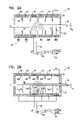
- FIG. 1Ais a schematic, cross-sectional illustration of an electrode assembly for applying current to a nerve, in accordance with a preferred embodiment of the present invention
- FIG. 1Bis a schematic pictorial illustration of the electrode assembly of FIG. 1A , in accordance with a preferred embodiment of the present invention
- FIGS. 2A and 2Bare schematic, cross-sectional illustrations of other electrode assemblies for applying current to a nerve, in accordance with respective preferred embodiments of the present invention.
- FIGS. 3A , 3 B, and 3 Care schematic, cross-sectional illustrations of yet other electrode assemblies for applying current to a nerve, in accordance with respective preferred embodiments of the present invention.
- FIG. 4is a schematic, cross-sectional illustration of still another electrode assembly for applying current to a nerve, in accordance with a preferred embodiment of the present invention
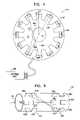
- FIG. 5is a schematic, pictorial illustration of an additional electrode assembly for applying current to a nerve, in accordance with a preferred embodiment of the present invention
- FIG. 6is a graph modeling a calculated activation function over a range of distances from the central axis of a nerve to which current is applied using an electrode assembly such as that shown in FIG. 1A , in accordance with a preferred embodiment of the present invention.
- FIG. 7is a graph modeling a calculated activation function over a portion of the length of a nerve to which current is applied using an electrode assembly such as that shown in FIG. 2A , in accordance with a preferred embodiment of the present invention.
- FIG. 1Ais a schematic, cross-sectional illustration of an electrode assembly 20 for applying current to a nerve 30 , in accordance with a preferred embodiment of the present invention.
- FIG. 1Bis a schematic pictorial illustration of electrode assembly 20 , in accordance with a preferred embodiment of the present invention. It is noted that although the various electrode assemblies shown in the figures generally contain cylindrical configurations of their elements, other geometrical configurations, such as non-rotationally symmetric configurations, are also suitable for applying the principles of the present invention.
- a housing 22 of the electrode assemblymay form a complete circle around the nerve, or it may define an arc between approximately 0 and 90 degrees, between 90 and 180 degrees, between 180 and 350 degrees, or between 350 and 359 degrees around the nerve. (One such preferred embodiment, shown in FIG. 1B , includes the housing and the electrodes defining an arc of 270 degrees.)
- electrode assemblycomprises a cathode 40 , a primary inhibiting anode 42 , and a secondary inhibiting anode 44 .
- Each of these electrodesis fixed within housing 22 of the electrode assembly.
- Insulating elements 24which are typically either part of the body of the housing or affixed thereto, are preferably placed so as to separate the electrodes, and to guide current from one of the electrodes towards the nerve prior to being taken up by another one of the electrodes.
- the insulating elementsare closer to nerve 30 than are the electrodes.
- insulating elements 24are generally flush with the faces of the electrodes.
- cathodic current driven through cathode 40 by a control unitstimulates fibers within nerve 30 to generate action potentials which travel in both directions within the nerve—i.e., towards anodes 42 and 44 (“the anodal direction”), and in the opposite direction, out of housing 22 , towards a target (“the target direction”).
- Anodal current driven through anode 42is typically applied so as to inhibit the action potentials which were induced by the cathodic current, and which subsequently traveled in the anodal direction.
- current applied by secondary inhibiting anode 44is of lower magnitude than the current applied by primary inhibiting anode 42 .
- the “virtual cathode” effect induced by the primary anodal currentis minimized.
- application of the primary and secondary anodal currents in appropriate ratiosis configured to generally minimize the virtual cathode effect.
- the ratio of the primary to the secondary anodal currentranges from 2:1 to 10:1.
- FIG. 2Ais a schematic, cross-sectional illustration of an electrode assembly 60 , in accordance with another preferred embodiment of the present invention.
- Electrode assembly 60comprises a cathode 70 , a primary inhibiting anode 72 , and a secondary inhibiting anode 74 , which are typically driven in a manner analogous to that described hereinabove with respect to cathode 40 and primary and secondary inhibiting anodes 42 and 44 .
- electrode assembly 60additionally comprises a tertiary anode 76 , which is employed to reduce any virtual cathode effect which may be induced by secondary inhibiting anode 74 .
- the primary inhibiting anode, secondary inhibiting anode, and tertiary anodemay be configured to apply respective currents of 0.66, 0.25, and 0.09.
- the magnitude of the current from the tertiary anodeis sufficiently small, such that the virtual cathode effect resulting therefrom does not generate action potentials that interfere with the performance of electrode assembly 60 .
- additional anodesare provided in electrode assembly 60 .
- Electrode assembly 60preferably comprises a primary fiber-selection anode 78 , adjacent to cathode 70 and on the other side of the housing from anodes 72 , 74 , and 76 .
- the current applied by cathode 70typically induces bi-directional action potential propagation in fibers in nerve 30 having a range of diameters.
- the primary fiber-selection anodeis preferably driven to apply anodal current configured to block action potential propagation in these larger fibers of nerve 30 , and configured not to block action potential propagation in the smaller fibers.
- a given level of current applied through fiber-selection anode 78typically blocks action potentials in the larger fibers, while allowing passage of action potentials induced by the current from cathode 70 and traveling in the small fibers. Therefore, action potentials induced by the cathode continue to propagate in the smaller fibers, past primary fiber-selection anode 78 , out of housing 22 , and towards a target site.
- By increasing the current driven through the primary fiber-selection anodeprogressively smaller fibers are inhibited from propagating action potentials.
- by decreasing the application of current through primary fiber-selection anode 78larger fibers are able to propagate action potentials.
- a secondary fiber-selection anode 80is preferably incorporated into electrode assembly 60 , adjacent to the primary fiber-selection anode and on the far side of cathode 70 .
- secondary fiber-selection anode 80is preferably driven to apply a current to the nerve smaller than that applied by primary fiber-selection anode 78 , so as to counteract the virtual cathode effect which would otherwise, in some circumstances, induce action potential propagation responsive to the current applied by primary fiber-selection anode 78 .
- fixed ratios for the currents applied by anodes 72 , 74 , 76 , 78 , and 80are pre-defined and are set in hardware, e.g., by a set 82 of resistors R 1 , R 2 , R 3 , R 4 , and R 5 , which couple a single lead 86 coming from a control unit 90 to the respective anodes.
- a guide tube 88conveys lead 86 , in combination with a second lead 84 that drives cathode 70 , from control unit 90 to electrode assembly 60 .
- this embodimentprovides control over multiple anodes, and corresponding reduction of the virtual cathode effect, with a minimum number of leads.
- the various anodesare independently driven by the control unit via respective leads, so as to optimize the minimization of the virtual cathode effect and the maximization (when appropriate) of anodally-induced hyperpolarization.
- a combination of the two techniques describedare utilized, whereby, for example, anodes 72 , 74 , and 76 are driven by current in a single lead, and anodes 78 and 80 are driven by current in two additional, separate leads.
- electrode assembly 60(as well as the other electrode assemblies described herein, as appropriate) has physical dimensions configured so as to provide a relatively uniform activation function across the cross-section of nerve 30 .
- the distance L 1 separating the central longitudinal axis of nerve 30 from cathode 70 and from anodes 72 , 74 , 76 , 78 , and 80is typically at least approximately 1.5 times greater than the radius L 0 of the nerve. For many applications, L 1 is greater than two times L 0 .
- Insulating elements 24preferably separate cathode 70 from anodes 72 and 78 .
- additional insulating elements 24separate the various adjacent anodes in electrode assembly 60 .
- the insulating elementsdefine a characteristic closest “insulating element distance” L 2 to the axis of nerve 30 that is preferably at least approximately 1.5 times greater than L 0 . It will be appreciated that for structural reasons, spokes or other offshoots of the insulating elements may come closer to the nerve.
- the “functional” portions of the insulating elementsi.e., those portions which provide a substantial effect on the direction of current flow between the electrodes and through the nerve, preferably remain at a closest distance L 2 of at least 1.5*L 0 .
- L 2is set to be less than 1.5*L 0 , at the expense of some uniformity of the applied field.
- L 1is greater than or equal to L 2 .
- preferred values for L 1are in the range L 2 ⁇ L 1 ⁇ 1.5 (L 2 +w). Further preferably, L 2 +0.5w ⁇ L 1 ⁇ L 2 +w.
- the width w of the electrodesis approximately equal to 0.5*L 0 . (The width w, as well as other dimensions, are not drawn to scale in the figures.)
- L 0is between 1 and 2 mm
- L 2is preferably between 1.5 and 3 mm
- L 1is between 1.5 and 4 mm
- wis between 0.5 and 1 mm.
- FIG. 2Bis a schematic, cross-sectional illustration of an electrode assembly 61 , in accordance with another preferred embodiment of the present invention.
- Electrode assembly 61is generally similar to electrode assembly 60 , described hereinabove with reference to FIG. 2A , except for differences as described.
- electrode assembly 61provides each of five insulating elements 24 A, 24 B, 24 C, 24 D, and 24 E with a respective (typically different) distance to the axis of nerve 30 of L 2 (A), L 2 (B), L 2 (C), L 2 (D), and L 2 (E).
- L 2 (x) for any given one of the insulating elementsdecreases, the current density experienced by the nerve in a vicinity of the insulating element increases.
- L 2 (C) corresponding to insulating element 24 Cis relatively large, such that the current density in the nerve near anode 76 is low.
- FIG. 3Ais a schematic, cross-sectional illustration of an electrode assembly 110 , in accordance with a preferred embodiment of the present invention.
- Electrode assembly 110is analogous to electrode assembly 20 , described hereinabove with reference to FIG. 1A , except for differences as described.
- a cathode 120 of electrode assembly 110serves generally the same purpose as cathode 40 , while an elongated anode 122 preferably replaces anodes 42 and 44 .
- elongated anode 122is 0.5 mm-10 mm in length, although it may be longer or shorter responsive to the level of currents expected to be applied therethrough.
- Elongated anode 122when placed on or over nerve 30 , preferably has at least two levels of electrical impedance associated therewith, between respective sites on the elongated anode and the nerve.
- a biological material 92typically including fibrous tissue and body fluids, generally occupies some of the space between the electrodes and the nerve.
- the impedance governing the passage of current from elongated anode 122 to nerve 30is therefore typically a function of the properties of biological material 92 .
- a resistive element 124e.g., a shaped iridium oxide coating, a titanium nitrite coating, or a platinum iridium coating
- a resistive element 124preferably provides greater electrical impedance distal to cathode 120 than proximal thereto.
- the coatingundergoes a surface treatment (e.g., “sand blasting” or a chemical treatment), in which the effective microscopic surface area is increased by the treatment.
- a surface treatmente.g., “sand blasting” or a chemical treatment
- the proximal-to-the-cathode end of the coatingis more heavily treated by the surface treatment, and therefore has lower impedance.
- the geometry of the elongated anodeis configured so as to effect the change in impedance as described.
- the anodal current leaving the portion of elongated anode 122 distal to cathode 120minimizes the virtual cathode effect induced thereat by anodal current leaving the portion of elongated anode 122 proximal to cathode 120 .
- FIG. 3Bis a schematic, cross-sectional illustration of an electrode assembly 111 , in accordance with a preferred embodiment of the present invention.
- a current density in a vicinity of a primary anode 123is higher than a current density in a vicinity of a secondary anode 127 .
- the difference in current densitiesis preferably attained by having a width w 2 of anode 127 be at least 2-10 times higher than a corresponding width w 1 of anode 123 . In this manner, when generally the same current is passed through both anodes, the current density and thus the hyperpolarizing effect on the activation function—is greater near anode 123 than near anode 127 .
- FIG. 3Cis a schematic, cross-sectional illustration of an electrode assembly 112 , in accordance with a preferred embodiment of the present invention.
- the distance L 1 (B) between a primary anode 125 and the axis of nerve 30is preferably smaller than the distance L 1 (A) between a secondary anode 126 and the axis of the nerve.
- the distance of cathode 120 from the axisis similar to L 1 (A) (as shown), while in other embodiments (not shown) the distance is closer to L 1 (B).
- the geometrical configuration of the cathode and the anodes shown in FIG. 3Ctypically provides higher current density near the anode that is proximal to the cathode, and provides generally lower current density near the anode that is distal to the cathode.
- FIG. 4is a schematic, cross-sectional illustration of an electrode assembly 140 surrounding nerve 30 , which is driven by a control unit 160 to apply current to the nerve, in accordance with a preferred embodiment of the present invention.
- Two or more electrodes 150 fixed to a housing 142are placed at respective positions around the axis.
- electrodes 150comprise at least three, and preferably four or more electrodes.
- insulating elements 144are preferably disposed between adjacent electrodes. If there are only two electrodes, then control unit 160 preferably alternates the direction of the current driven between the two electrodes at a rate greater than 1000 Hz.
- control unit 160When there are three or more electrodes 150 , thereby defining a ring of electrodes, control unit 160 preferably cycles its driving of the electrodes in accordance with a stimulation protocol.
- a stimulation protocolfor three electrodes may include driving current between electrodes 1 and 2 , then 2 and 3 , then 3 and 1 , then 1 and 2 , etc., cycling through the combinations at an average rate of greater than 1000 Hz, or, for some applications, greater than 10,000 Hz.
- the stimulation cycling protocolis typically more complex, and is preferably configured to cause current to pass through or close to most or all fibers in the nerve at the longitudinal site where the ring of electrodes is placed.
- One such complex protocolincludes effectively creating a star out of successive current lines passing through the nerve. In FIG. 4 , an initial set of four such lines 152 , 154 , 156 , and 158 are shown.
- FIG. 5is a schematic, pictorial illustration of an electrode assembly 170 , in accordance with another preferred embodiment of the present invention.
- Electrode assembly 170comprises an anodal ring 172 of two or more anodes and a cathodic ring 192 of two or more cathodes.
- anodal ring 172comprises anodes 174 , 176 , 178 , 180 , 182 , and 184
- cathodic ring 192comprises cathodes 194 , 196 , 198 , 200 , 202 , and 204 .
- Each ring of electrodesis placed around the nerve axis, at a respective anodal or cathodic longitudinal site of the nerve.
- a control unitdrives anode 176 to drive current through nerve 30 to cathode 196 , in order to initiate generation of action potentials near cathode 196 and/or near a substantial portion of cathodic ring 192 .
- Cathode 196 and anode 176are preferably at mutually-opposed orientations with respect to the axis. In this manner, a greater portion of the current from anode 176 enters nerve 30 than if, for example, the control unit were to drive anode 176 to send the same amount of charge to cathode 202 . In this latter case, a substantial portion of the current leaving anode 176 would travel directly through the biological material surrounding nerve 30 , and not enter into nerve 30 .
- anode 176sends current to cathode 196
- anode 178sends current to cathode 198
- anode 180sends current to cathode 200 .
- an entire sweep of all of the electrodes in the two ringsis accomplished within 0.01-1 millisecond.
- fibers in the nerveare stimulated near the ring of cathodes, and inhibited near the ring of anodes, typically using substantially less current than if a solid anode ring and a solid cathode ring were placed around the nerve.
- steering of current to traverse or avoid certain regions in the cross-section of the nerveis readily attainable, using the techniques described herein, by suitable activation of the cathodes and/or anodes.
- FIG. 5shows only a single anodal ring 172 . It is noted that the use of rings of anodes and/or a ring of cathodes is preferably also applied, as appropriate, in combination with the cathode-anode-anode configuration of FIGS. 1A and 1B , or in combination with the anode-anode-cathode-anode-anode-anode configuration of FIGS. 2A and 2B .
- some of the electrodes(e.g., cathode 70 and anodes 72 and 78 ) comprise multiple electrodes disposed in a ring, while others of the electrodes (e.g., anodes 74 , 76 , and 80 ) are generally solid rings, each comprising only a single ring.
- FIG. 6is a graph modeling calculated activation function over a range of distances from the central axis of a nerve, in accordance with a preferred embodiment of the present invention.
- the graphmodels, in a simplified fashion, the activation function, at a cathodic site, produced in response to application of current by, for example, electrode assembly 20 ( FIG. 1A ) or electrode assembly 60 ( FIG. 2A ).
- the equation producing the graph shown in FIG. 6is:
- AF ⁇ ( r )I 2 ⁇ ⁇ ⁇ ⁇ ⁇ ⁇ 0 2 ⁇ ⁇ ⁇ ⁇ [ 1 + ( r R ) 2 - 2 ⁇ ( r R ) ⁇ ⁇ cos ⁇ ⁇ ⁇ ] - 1.5 ⁇ d ⁇ , where r is the radius from the central axis of the nerve, and R is the distance of an electrode ring from the axis.
- L 0 in the figureshows the radius of a typical nerve, and L 2 shows the distance to an insulating element.
- the amount of change of the activation function within the nerve(r ⁇ L 0 ) is significantly smaller than the amount of change of the activation function outside the nerve (r>L 0 ).
- FIG. 7is a graph modeling calculated activation function over a portion of the length of nerve 30 , when current is applied using an electrode assembly such as that shown in FIG. 2A (without applying current through anodes 78 and 80 ), in accordance with a preferred embodiment of the present invention.
- Each one of the electrodesgenerates its own activation function responsive to the applied currents, as modeled in FIG. 7 .
- the sum of the effect of each of the anodal activation functionsis seen in the fourth data line in FIG. 7 , labeled “summed anodes.”
- This linedemonstrates that the hyperpolarization portion of the activation function due to anodal current A 2 significantly counteracts the depolarization portion of the activation function due to anodal current A 1 .
- the peaks 222 at z>0are generally not of sufficient magnitude to excessively stimulate the nerve fibers within nerve 30 by means of the virtual cathode effect. Nevertheless, the maximum hyperpolarization peak 220 of the “summed anodes” curve remains strong, sufficient to inhibit action potential propagation in a substantial proportion of the fibers of nerve 30 .
- the ratio of the magnitude of peak 220 to the magnitude of the highest of depolarization peaks 222is typically at least 8:1, and is preferably greater than 10:1.
- the bottom data line in FIG. 7shows the combined effect on the activation function due to the summed anode activation function and the activation function due to the cathode. It is noted that the use of the various anodes does not excessively decrease either the magnitude of the desired depolarizing peak 230 , or that of the desired hyperpolarizing peak 240 of the combined activation function.
Landscapes
- Health & Medical Sciences (AREA)
- General Health & Medical Sciences (AREA)
- Animal Behavior & Ethology (AREA)
- Veterinary Medicine (AREA)
- Public Health (AREA)
- Life Sciences & Earth Sciences (AREA)
- Engineering & Computer Science (AREA)
- Biomedical Technology (AREA)
- Nuclear Medicine, Radiotherapy & Molecular Imaging (AREA)
- Radiology & Medical Imaging (AREA)
- Neurosurgery (AREA)
- Neurology (AREA)
- Heart & Thoracic Surgery (AREA)
- Cardiology (AREA)
- Orthopedic Medicine & Surgery (AREA)
- Pain & Pain Management (AREA)
- Gastroenterology & Hepatology (AREA)
- Electrotherapy Devices (AREA)
- Prostheses (AREA)
Abstract
Description
∇(σ∇U)=4Πj,
where U is the potential, σ is the conductance tensor specifying the conductance of the various materials (electrode housing, axon, intracellular fluid, etc.), and j is a scalar function representing the current source density specifying the locations of current injection. The activation function is found by solving this partial differential equation for U. If the axon is defined to lie in the z direction, then the activation function is:
where Ielis the electrode current. It is seen that when σ and d are held constant, and for a constant positive Iel(to correspond to anodal current), the minimum value of the activation function is negative, and is attained at z=0, i.e., at the point on the nerve closest to the source of the anodal current. Thus, the most negative point on the activation function corresponds to the place on a nerve where hyperpolarization is maximized, namely at the point on the nerve closest to the anode.
- van den Honert C et al., “A technique for collision block of peripheral nerve: Single stimulus analysis,” MP-11, IEEE Trans. Biomed. Eng. 28:373-378 (1981)
- van den Honert C et al., “A technique for collision block of peripheral nerve: Frequency dependence,” MP-12, IEEE Trans. Biomed. Eng. 28:379-382 (1981)
where r is the radius from the central axis of the nerve, and R is the distance of an electrode ring from the axis. L0 in the figure shows the radius of a typical nerve, and L2 shows the distance to an insulating element. As noted above, the amount of change of the activation function within the nerve (r<L0) is significantly smaller than the amount of change of the activation function outside the nerve (r>L0).
- a U.S. patent application to Gross et al., filed on even date with the present patent application, entitled, “Selective nerve fiber stimulation for treating heart conditions,”
- U.S. Provisional patent application Ser. No. 60/383,157 to Ayal et al., filed May 23, 2002, entitled, “Inverse recruitment for autonomic nerve systems,”
- PCT Patent Application PCT/IL02/00068 to Cohen et al., filed Jan. 23, 2002, entitled, “Treatment of disorders by unidirectional nerve stimulation,”
- U.S. patent application Ser. No. 09/944,913 to Cohen and Gross, filed Aug. 31, 2001, entitled, “Treatment of disorders by unidirectional nerve stimulation,” and
- U.S. patent application Ser. No. 09/824,682 to Cohen and Ayal, filed Apr. 4, 2001, entitled “Method and apparatus for selective control of nerve fibers.”
Claims (42)
Priority Applications (5)
| Application Number | Priority Date | Filing Date | Title |
|---|---|---|---|
| US10/948,516US7346398B2 (en) | 2001-08-31 | 2004-09-23 | Electrode assembly for nerve control |
| US11/981,301US8065021B2 (en) | 2002-05-23 | 2007-10-30 | Electrode assembly for nerve control |
| US13/271,720US8494655B2 (en) | 2002-05-23 | 2011-10-12 | Electrode devices with resistive elements |
| US13/939,892US8725271B2 (en) | 2002-05-23 | 2013-07-11 | Electrode device with elongated electrode |
| US14/243,262US20140214135A1 (en) | 2002-05-23 | 2014-04-02 | Dissolvable electrode device |
Applications Claiming Priority (5)
| Application Number | Priority Date | Filing Date | Title |
|---|---|---|---|
| US09/944,913US6684105B2 (en) | 2001-08-31 | 2001-08-31 | Treatment of disorders by unidirectional nerve stimulation |
| PCT/IL2002/000068WO2003018113A1 (en) | 2001-08-31 | 2002-01-23 | Treatment of disorders by unidirectional nerve stimulation |
| US38315702P | 2002-05-23 | 2002-05-23 | |
| US10/205,474US6907295B2 (en) | 2001-08-31 | 2002-07-24 | Electrode assembly for nerve control |
| US10/948,516US7346398B2 (en) | 2001-08-31 | 2004-09-23 | Electrode assembly for nerve control |
Related Parent Applications (1)
| Application Number | Title | Priority Date | Filing Date |
|---|---|---|---|
| US10/205,474ContinuationUS6907295B2 (en) | 2001-04-26 | 2002-07-24 | Electrode assembly for nerve control |
Related Child Applications (1)
| Application Number | Title | Priority Date | Filing Date |
|---|---|---|---|
| US11/981,301ContinuationUS8065021B2 (en) | 2002-05-23 | 2007-10-30 | Electrode assembly for nerve control |
Publications (2)
| Publication Number | Publication Date |
|---|---|
| US20050038490A1 US20050038490A1 (en) | 2005-02-17 |
| US7346398B2true US7346398B2 (en) | 2008-03-18 |
Family
ID=30117851
Family Applications (5)
| Application Number | Title | Priority Date | Filing Date |
|---|---|---|---|
| US10/205,474Expired - Fee RelatedUS6907295B2 (en) | 2001-04-26 | 2002-07-24 | Electrode assembly for nerve control |
| US10/948,516Expired - LifetimeUS7346398B2 (en) | 2001-08-31 | 2004-09-23 | Electrode assembly for nerve control |
| US11/981,301Expired - Fee RelatedUS8065021B2 (en) | 2002-05-23 | 2007-10-30 | Electrode assembly for nerve control |
| US13/271,720Expired - Fee RelatedUS8494655B2 (en) | 2002-05-23 | 2011-10-12 | Electrode devices with resistive elements |
| US13/939,892Expired - Fee RelatedUS8725271B2 (en) | 2002-05-23 | 2013-07-11 | Electrode device with elongated electrode |
Family Applications Before (1)
| Application Number | Title | Priority Date | Filing Date |
|---|---|---|---|
| US10/205,474Expired - Fee RelatedUS6907295B2 (en) | 2001-04-26 | 2002-07-24 | Electrode assembly for nerve control |
Family Applications After (3)
| Application Number | Title | Priority Date | Filing Date |
|---|---|---|---|
| US11/981,301Expired - Fee RelatedUS8065021B2 (en) | 2002-05-23 | 2007-10-30 | Electrode assembly for nerve control |
| US13/271,720Expired - Fee RelatedUS8494655B2 (en) | 2002-05-23 | 2011-10-12 | Electrode devices with resistive elements |
| US13/939,892Expired - Fee RelatedUS8725271B2 (en) | 2002-05-23 | 2013-07-11 | Electrode device with elongated electrode |
Country Status (5)
| Country | Link |
|---|---|
| US (5) | US6907295B2 (en) |
| EP (1) | EP1545693B1 (en) |
| AU (1) | AU2003230184A1 (en) |
| IL (1) | IL164879A0 (en) |
| WO (1) | WO2003099373A2 (en) |
Cited By (95)
| Publication number | Priority date | Publication date | Assignee | Title |
|---|---|---|---|---|
| US20070135856A1 (en)* | 2003-02-03 | 2007-06-14 | Enteromedics, Inc. | Bulimia treatment |
| US20070203527A1 (en)* | 2003-05-23 | 2007-08-30 | Tamir Ben-David | Parasympathetic stimulation for termination of non-sinus atrial tachycardia |
| US20070255379A1 (en)* | 2003-06-04 | 2007-11-01 | Williams Michael S | Intravascular device for neuromodulation |
| US20080103545A1 (en)* | 2006-10-13 | 2008-05-01 | Apnex Medical, Inc. | Obstructive sleep apnea treatment devices, systems and methods |
| US20080125827A1 (en)* | 2002-07-24 | 2008-05-29 | Biocontrol Medical Ltd. | Selective nerve fiber stimulation for treating heart conditions |
| US20080161895A1 (en)* | 2002-05-23 | 2008-07-03 | Biocontrol Medical Ltd. | Electrode assembly for nerve control |
| US20080281365A1 (en)* | 2007-05-09 | 2008-11-13 | Tweden Katherine S | Neural signal duty cycle |
| US20090204173A1 (en)* | 2007-11-05 | 2009-08-13 | Zi-Ping Fang | Multi-Frequency Neural Treatments and Associated Systems and Methods |
| US20100023088A1 (en)* | 2008-03-27 | 2010-01-28 | Stack Richard S | System and method for transvascularly stimulating contents of the carotid sheath |
| US20100094375A1 (en)* | 2005-08-17 | 2010-04-15 | Enteromedics Inc. | Neural electrode treatment |
| US20100174341A1 (en)* | 2008-12-31 | 2010-07-08 | Bolea Stephen L | Obstructive Sleep Apnea Treatment Devices, Systems and Methods |
| US20100274317A1 (en)* | 2009-04-22 | 2010-10-28 | Jon Parker | Devices for controlling high frequency spinal cord modulation for inhibiting pain, and associated systems and methods, including simplified contact selection |
| US20110022124A1 (en)* | 2008-11-13 | 2011-01-27 | Mark Zdeblick | Multiplexed multi-electrode neurostimulation devices |
| US20110130809A1 (en)* | 2008-11-13 | 2011-06-02 | Proteus Biomedical, Inc. | Pacing and Stimulation Apparatus and Methods |
| US20110224749A1 (en)* | 2001-08-31 | 2011-09-15 | Bio Control Medical (B.C.M.) Ltd. | Nerve stimulation techniques |
| US8386046B2 (en) | 2011-01-28 | 2013-02-26 | Apnex Medical, Inc. | Screening devices and methods for obstructive sleep apnea therapy |
| US8509906B2 (en) | 2009-01-29 | 2013-08-13 | Nevro Corporation | Systems and methods for producing asynchronous neural responses to treat pain and/or other patient conditions |
| US8565896B2 (en) | 2010-11-22 | 2013-10-22 | Bio Control Medical (B.C.M.) Ltd. | Electrode cuff with recesses |
| US8571654B2 (en) | 2012-01-17 | 2013-10-29 | Cyberonics, Inc. | Vagus nerve neurostimulator with multiple patient-selectable modes for treating chronic cardiac dysfunction |
| US8577458B1 (en) | 2011-12-07 | 2013-11-05 | Cyberonics, Inc. | Implantable device for providing electrical stimulation of cervical vagus nerves for treatment of chronic cardiac dysfunction with leadless heart rate monitoring |
| US8600505B2 (en) | 2011-12-07 | 2013-12-03 | Cyberonics, Inc. | Implantable device for facilitating control of electrical stimulation of cervical vagus nerves for treatment of chronic cardiac dysfunction |
| US8630709B2 (en) | 2011-12-07 | 2014-01-14 | Cyberonics, Inc. | Computer-implemented system and method for selecting therapy profiles of electrical stimulation of cervical vagus nerves for treatment of chronic cardiac dysfunction |
| US8644919B2 (en) | 2008-11-13 | 2014-02-04 | Proteus Digital Health, Inc. | Shielded stimulation and sensing system and method |
| US8649874B2 (en) | 2010-11-30 | 2014-02-11 | Nevro Corporation | Extended pain relief via high frequency spinal cord modulation, and associated systems and methods |
| US8676331B2 (en) | 2012-04-02 | 2014-03-18 | Nevro Corporation | Devices for controlling spinal cord modulation for inhibiting pain, and associated systems and methods, including controllers for automated parameter selection |
| US8688212B2 (en) | 2012-07-20 | 2014-04-01 | Cyberonics, Inc. | Implantable neurostimulator-implemented method for managing bradycardia through vagus nerve stimulation |
| US8700150B2 (en) | 2012-01-17 | 2014-04-15 | Cyberonics, Inc. | Implantable neurostimulator for providing electrical stimulation of cervical vagus nerves for treatment of chronic cardiac dysfunction with bounded titration |
| US8718791B2 (en) | 2003-05-23 | 2014-05-06 | Bio Control Medical (B.C.M.) Ltd. | Electrode cuffs |
| US8825164B2 (en) | 2010-06-11 | 2014-09-02 | Enteromedics Inc. | Neural modulation devices and methods |
| US8855771B2 (en) | 2011-01-28 | 2014-10-07 | Cyberonics, Inc. | Screening devices and methods for obstructive sleep apnea therapy |
| US8880192B2 (en) | 2012-04-02 | 2014-11-04 | Bio Control Medical (B.C.M.) Ltd. | Electrode cuffs |
| US8918181B2 (en) | 2010-11-16 | 2014-12-23 | The Board Of Trustees Of The Leland Stanford Junior University | Systems and methods for treatment of dry eye |
| US8918190B2 (en) | 2011-12-07 | 2014-12-23 | Cyberonics, Inc. | Implantable device for evaluating autonomic cardiovascular drive in a patient suffering from chronic cardiac dysfunction |
| US8918191B2 (en) | 2011-12-07 | 2014-12-23 | Cyberonics, Inc. | Implantable device for providing electrical stimulation of cervical vagus nerves for treatment of chronic cardiac dysfunction with bounded titration |
| US8923964B2 (en) | 2012-11-09 | 2014-12-30 | Cyberonics, Inc. | Implantable neurostimulator-implemented method for enhancing heart failure patient awakening through vagus nerve stimulation |
| US8996137B2 (en) | 2013-04-19 | 2015-03-31 | Oculeve, Inc. | Nasal stimulation devices and methods |
| US9186511B2 (en) | 2006-10-13 | 2015-11-17 | Cyberonics, Inc. | Obstructive sleep apnea treatment devices, systems and methods |
| US9205262B2 (en) | 2011-05-12 | 2015-12-08 | Cyberonics, Inc. | Devices and methods for sleep apnea treatment |
| US9265956B2 (en) | 2013-03-08 | 2016-02-23 | Oculeve, Inc. | Devices and methods for treating dry eye in animals |
| US9272143B2 (en) | 2014-05-07 | 2016-03-01 | Cyberonics, Inc. | Responsive neurostimulation for the treatment of chronic cardiac dysfunction |
| US9278215B2 (en) | 2011-09-08 | 2016-03-08 | Nevro Corporation | Selective high frequency spinal cord modulation for inhibiting pain, including cephalic and/or total body pain with reduced side effects, and associated systems and methods |
| US9409019B2 (en) | 2009-07-28 | 2016-08-09 | Nevro Corporation | Linked area parameter adjustment for spinal cord stimulation and associated systems and methods |
| US9409024B2 (en) | 2014-03-25 | 2016-08-09 | Cyberonics, Inc. | Neurostimulation in a neural fulcrum zone for the treatment of chronic cardiac dysfunction |
| US9415224B2 (en) | 2014-04-25 | 2016-08-16 | Cyberonics, Inc. | Neurostimulation and recording of physiological response for the treatment of chronic cardiac dysfunction |
| US9452290B2 (en) | 2012-11-09 | 2016-09-27 | Cyberonics, Inc. | Implantable neurostimulator-implemented method for managing tachyarrhythmia through vagus nerve stimulation |
| US9504832B2 (en) | 2014-11-12 | 2016-11-29 | Cyberonics, Inc. | Neurostimulation titration process via adaptive parametric modification |
| US9511228B2 (en) | 2014-01-14 | 2016-12-06 | Cyberonics, Inc. | Implantable neurostimulator-implemented method for managing hypertension through renal denervation and vagus nerve stimulation |
| US9533153B2 (en) | 2014-08-12 | 2017-01-03 | Cyberonics, Inc. | Neurostimulation titration process |
| US9643008B2 (en) | 2012-11-09 | 2017-05-09 | Cyberonics, Inc. | Implantable neurostimulator-implemented method for enhancing post-exercise recovery through vagus nerve stimulation |
| US9643022B2 (en) | 2013-06-17 | 2017-05-09 | Nyxoah SA | Flexible control housing for disposable patch |
| US9643011B2 (en) | 2013-03-14 | 2017-05-09 | Cyberonics, Inc. | Implantable neurostimulator-implemented method for managing tachyarrhythmic risk during sleep through vagus nerve stimulation |
| US9687652B2 (en) | 2014-07-25 | 2017-06-27 | Oculeve, Inc. | Stimulation patterns for treating dry eye |
| US9713719B2 (en) | 2014-04-17 | 2017-07-25 | Cyberonics, Inc. | Fine resolution identification of a neural fulcrum for the treatment of chronic cardiac dysfunction |
| US9717627B2 (en) | 2013-03-12 | 2017-08-01 | Oculeve, Inc. | Implant delivery devices, systems, and methods |
| US9737716B2 (en) | 2014-08-12 | 2017-08-22 | Cyberonics, Inc. | Vagus nerve and carotid baroreceptor stimulation system |
| US9737712B2 (en) | 2014-10-22 | 2017-08-22 | Oculeve, Inc. | Stimulation devices and methods for treating dry eye |
| US9764150B2 (en) | 2014-10-22 | 2017-09-19 | Oculeve, Inc. | Contact lens for increasing tear production |
| US9770583B2 (en) | 2014-02-25 | 2017-09-26 | Oculeve, Inc. | Polymer formulations for nasolacrimal stimulation |
| US9770599B2 (en) | 2014-08-12 | 2017-09-26 | Cyberonics, Inc. | Vagus nerve stimulation and subcutaneous defibrillation system |
| US9821159B2 (en) | 2010-11-16 | 2017-11-21 | The Board Of Trustees Of The Leland Stanford Junior University | Stimulation devices and methods |
| US9833614B1 (en) | 2012-06-22 | 2017-12-05 | Nevro Corp. | Autonomic nervous system control via high frequency spinal cord modulation, and associated systems and methods |
| US9849289B2 (en) | 2009-10-20 | 2017-12-26 | Nyxoah SA | Device and method for snoring detection and control |
| US9855032B2 (en) | 2012-07-26 | 2018-01-02 | Nyxoah SA | Transcutaneous power conveyance device |
| US9895539B1 (en) | 2013-06-10 | 2018-02-20 | Nevro Corp. | Methods and systems for disease treatment using electrical stimulation |
| US9943686B2 (en) | 2009-10-20 | 2018-04-17 | Nyxoah SA | Method and device for treating sleep apnea based on tongue movement |
| US9950169B2 (en) | 2014-04-25 | 2018-04-24 | Cyberonics, Inc. | Dynamic stimulation adjustment for identification of a neural fulcrum |
| US9956393B2 (en) | 2015-02-24 | 2018-05-01 | Elira, Inc. | Systems for increasing a delay in the gastric emptying time for a patient using a transcutaneous electro-dermal patch |
| US9999773B2 (en) | 2013-10-30 | 2018-06-19 | Cyberonics, Inc. | Implantable neurostimulator-implemented method utilizing multi-modal stimulation parameters |
| US10052097B2 (en) | 2012-07-26 | 2018-08-21 | Nyxoah SA | Implant unit delivery tool |
| US10118035B2 (en) | 2015-02-24 | 2018-11-06 | Elira, Inc. | Systems and methods for enabling appetite modulation and/or improving dietary compliance using an electro-dermal patch |
| US10149978B1 (en) | 2013-11-07 | 2018-12-11 | Nevro Corp. | Spinal cord modulation for inhibiting pain via short pulse width waveforms, and associated systems and methods |
| US10188856B1 (en) | 2011-12-07 | 2019-01-29 | Cyberonics, Inc. | Implantable device for providing electrical stimulation of cervical vagus nerves for treatment of chronic cardiac dysfunction |
| US10207108B2 (en) | 2014-10-22 | 2019-02-19 | Oculeve, Inc. | Implantable nasal stimulator systems and methods |
| US10252048B2 (en) | 2016-02-19 | 2019-04-09 | Oculeve, Inc. | Nasal stimulation for rhinitis, nasal congestion, and ocular allergies |
| US10335302B2 (en) | 2015-02-24 | 2019-07-02 | Elira, Inc. | Systems and methods for using transcutaneous electrical stimulation to enable dietary interventions |
| US10376145B2 (en) | 2015-02-24 | 2019-08-13 | Elira, Inc. | Systems and methods for enabling a patient to achieve a weight loss objective using an electrical dermal patch |
| US10426958B2 (en) | 2015-12-04 | 2019-10-01 | Oculeve, Inc. | Intranasal stimulation for enhanced release of ocular mucins and other tear proteins |
| US10493275B2 (en) | 2009-04-22 | 2019-12-03 | Nevro Corp. | Spinal cord modulation for inducing paresthetic and anesthetic effects, and associated systems and methods |
| US10610095B2 (en) | 2016-12-02 | 2020-04-07 | Oculeve, Inc. | Apparatus and method for dry eye forecast and treatment recommendation |
| US10751537B2 (en) | 2009-10-20 | 2020-08-25 | Nyxoah SA | Arced implant unit for modulation of nerves |
| US10765863B2 (en) | 2015-02-24 | 2020-09-08 | Elira, Inc. | Systems and methods for using a transcutaneous electrical stimulation device to deliver titrated therapy |
| US10799701B2 (en) | 2016-03-30 | 2020-10-13 | Nevro Corp. | Systems and methods for identifying and treating patients with high-frequency electrical signals |
| US10814137B2 (en) | 2012-07-26 | 2020-10-27 | Nyxoah SA | Transcutaneous power conveyance device |
| US10864367B2 (en) | 2015-02-24 | 2020-12-15 | Elira, Inc. | Methods for using an electrical dermal patch in a manner that reduces adverse patient reactions |
| US10918864B2 (en) | 2016-05-02 | 2021-02-16 | Oculeve, Inc. | Intranasal stimulation for treatment of meibomian gland disease and blepharitis |
| US11253712B2 (en) | 2012-07-26 | 2022-02-22 | Nyxoah SA | Sleep disordered breathing treatment apparatus |
| US11318310B1 (en) | 2015-10-26 | 2022-05-03 | Nevro Corp. | Neuromodulation for altering autonomic functions, and associated systems and methods |
| US11383083B2 (en) | 2014-02-11 | 2022-07-12 | Livanova Usa, Inc. | Systems and methods of detecting and treating obstructive sleep apnea |
| US11446504B1 (en) | 2016-05-27 | 2022-09-20 | Nevro Corp. | High frequency electromagnetic stimulation for modulating cells, including spontaneously active and quiescent cells, and associated systems and methods |
| US11590352B2 (en) | 2019-01-29 | 2023-02-28 | Nevro Corp. | Ramped therapeutic signals for modulating inhibitory interneurons, and associated systems and methods |
| US11596798B2 (en) | 2016-01-25 | 2023-03-07 | Nevro Corp | Treatment of congestive heart failure with electrical stimulation, and associated systems and methods |
| US11602634B2 (en) | 2019-01-17 | 2023-03-14 | Nevro Corp. | Sensory threshold adaptation for neurological therapy screening and/or electrode selection, and associated systems and methods |
| US11957895B2 (en) | 2015-02-24 | 2024-04-16 | Elira, Inc. | Glucose-based modulation of electrical stimulation to enable weight loss |
| US12268876B2 (en) | 2005-09-26 | 2025-04-08 | Flathead Partners, Llc | Neural blocking therapy |
| US12427310B2 (en) | 2016-09-29 | 2025-09-30 | Theranica Bio-Electronics Ltd. | Application of an electrical amplitude-modulated signal to a subject |
Families Citing this family (154)
| Publication number | Priority date | Publication date | Assignee | Title |
|---|---|---|---|---|
| US6650943B1 (en) | 2000-04-07 | 2003-11-18 | Advanced Bionics Corporation | Fully implantable neurostimulator for cavernous nerve stimulation as a therapy for erectile dysfunction and other sexual dysfunction |
| US6885895B1 (en)* | 2001-04-26 | 2005-04-26 | Advanced Bionics Corporation | Methods and systems for electrical and/or drug stimulation as a therapy for erectile dysfunction |
| US20050240229A1 (en)* | 2001-04-26 | 2005-10-27 | Whitehurst Tood K | Methods and systems for stimulation as a therapy for erectile dysfunction |
| US7904176B2 (en)* | 2006-09-07 | 2011-03-08 | Bio Control Medical (B.C.M.) Ltd. | Techniques for reducing pain associated with nerve stimulation |
| US7974693B2 (en)* | 2001-08-31 | 2011-07-05 | Bio Control Medical (B.C.M.) Ltd. | Techniques for applying, configuring, and coordinating nerve fiber stimulation |
| US20090005845A1 (en)* | 2007-06-26 | 2009-01-01 | Tamir Ben David | Intra-Atrial parasympathetic stimulation |
| US7885709B2 (en)* | 2001-08-31 | 2011-02-08 | Bio Control Medical (B.C.M.) Ltd. | Nerve stimulation for treating disorders |
| US20140046407A1 (en)* | 2001-08-31 | 2014-02-13 | Bio Control Medical (B.C.M.) Ltd. | Nerve stimulation techniques |
| US8615294B2 (en)* | 2008-08-13 | 2013-12-24 | Bio Control Medical (B.C.M.) Ltd. | Electrode devices for nerve stimulation and cardiac sensing |
| US7778703B2 (en)* | 2001-08-31 | 2010-08-17 | Bio Control Medical (B.C.M.) Ltd. | Selective nerve fiber stimulation for treating heart conditions |
| US7308303B2 (en)* | 2001-11-01 | 2007-12-11 | Advanced Bionics Corporation | Thrombolysis and chronic anticoagulation therapy |
| US20060116739A1 (en)* | 2002-05-23 | 2006-06-01 | Nir Betser | Electrode assembly for nerve control |
| US8204591B2 (en)* | 2002-05-23 | 2012-06-19 | Bio Control Medical (B.C.M.) Ltd. | Techniques for prevention of atrial fibrillation |
| US7321793B2 (en) | 2003-06-13 | 2008-01-22 | Biocontrol Medical Ltd. | Vagal stimulation for atrial fibrillation therapy |
| US7844346B2 (en)* | 2002-05-23 | 2010-11-30 | Biocontrol Medical Ltd. | Electrode assembly for nerve control |
| US7561922B2 (en)* | 2004-12-22 | 2009-07-14 | Biocontrol Medical Ltd. | Construction of electrode assembly for nerve control |
| US7885711B2 (en)* | 2003-06-13 | 2011-02-08 | Bio Control Medical (B.C.M.) Ltd. | Vagal stimulation for anti-embolic therapy |
| US7113816B2 (en)* | 2002-06-18 | 2006-09-26 | Nippon Cable System Inc. | Ultra-miniature in-vivo electrode used for measuring bioelectrical neural activity |
| US7860570B2 (en) | 2002-06-20 | 2010-12-28 | Boston Scientific Neuromodulation Corporation | Implantable microstimulators and methods for unidirectional propagation of action potentials |
| US7203548B2 (en) | 2002-06-20 | 2007-04-10 | Advanced Bionics Corporation | Cavernous nerve stimulation via unidirectional propagation of action potentials |
| US7292890B2 (en) | 2002-06-20 | 2007-11-06 | Advanced Bionics Corporation | Vagus nerve stimulation via unidirectional propagation of action potentials |
| US20040015205A1 (en)* | 2002-06-20 | 2004-01-22 | Whitehurst Todd K. | Implantable microstimulators with programmable multielectrode configuration and uses thereof |
| US7627384B2 (en) | 2004-11-15 | 2009-12-01 | Bio Control Medical (B.C.M.) Ltd. | Techniques for nerve stimulation |
| US20100010603A1 (en) | 2008-07-09 | 2010-01-14 | Tamir Ben-David | Electrode cuffs |
| WO2004110549A2 (en)* | 2003-06-13 | 2004-12-23 | Biocontrol Medical Ltd. | Applications of vagal stimulation |
| US7364755B2 (en)* | 2003-07-07 | 2008-04-29 | Synthon Ip Inc. | Modified calcium phosphate excipient |
| US8606356B2 (en) | 2003-09-18 | 2013-12-10 | Cardiac Pacemakers, Inc. | Autonomic arousal detection system and method |
| US8002553B2 (en) | 2003-08-18 | 2011-08-23 | Cardiac Pacemakers, Inc. | Sleep quality data collection and evaluation |
| US7392093B2 (en)* | 2003-09-26 | 2008-06-24 | Advanced Neuromodulation Systems, Inc. | Electrical stimulation system including a device for partially shielding electrical energy emitted from one or more electrical stimulation leads implanted in a human's body |
| US9020595B2 (en) | 2003-12-24 | 2015-04-28 | Cardiac Pacemakers, Inc. | Baroreflex activation therapy with conditional shut off |
| US7460906B2 (en) | 2003-12-24 | 2008-12-02 | Cardiac Pacemakers, Inc. | Baroreflex stimulation to treat acute myocardial infarction |
| US7706884B2 (en) | 2003-12-24 | 2010-04-27 | Cardiac Pacemakers, Inc. | Baroreflex stimulation synchronized to circadian rhythm |
| US7647114B2 (en) | 2003-12-24 | 2010-01-12 | Cardiac Pacemakers, Inc. | Baroreflex modulation based on monitored cardiovascular parameter |
| US7295881B2 (en)* | 2003-12-29 | 2007-11-13 | Biocontrol Medical Ltd. | Nerve-branch-specific action-potential activation, inhibition, and monitoring |
| US8467875B2 (en) | 2004-02-12 | 2013-06-18 | Medtronic, Inc. | Stimulation of dorsal genital nerves to treat urologic dysfunctions |
| PL1759536T3 (en)* | 2004-06-01 | 2011-10-31 | Kwalata Trading Ltd | In vitro techniques for use with stem cells |
| US7747323B2 (en) | 2004-06-08 | 2010-06-29 | Cardiac Pacemakers, Inc. | Adaptive baroreflex stimulation therapy for disordered breathing |
| US7239918B2 (en) | 2004-06-10 | 2007-07-03 | Ndi Medical Inc. | Implantable pulse generator for providing functional and/or therapeutic stimulation of muscles and/or nerves and/or central nervous system tissue |
| US8165692B2 (en) | 2004-06-10 | 2012-04-24 | Medtronic Urinary Solutions, Inc. | Implantable pulse generator power management |
| US8195304B2 (en) | 2004-06-10 | 2012-06-05 | Medtronic Urinary Solutions, Inc. | Implantable systems and methods for acquisition and processing of electrical signals |
| US9205255B2 (en) | 2004-06-10 | 2015-12-08 | Medtronic Urinary Solutions, Inc. | Implantable pulse generator systems and methods for providing functional and/or therapeutic stimulation of muscles and/or nerves and/or central nervous system tissue |
| US8116881B2 (en)* | 2004-06-10 | 2012-02-14 | Bio Control Medical (B.C.M.) Ltd | Electrode assembly for nerve control |
| US7761167B2 (en) | 2004-06-10 | 2010-07-20 | Medtronic Urinary Solutions, Inc. | Systems and methods for clinician control of stimulation systems |
| US9308382B2 (en) | 2004-06-10 | 2016-04-12 | Medtronic Urinary Solutions, Inc. | Implantable pulse generator systems and methods for providing functional and/or therapeutic stimulation of muscles and/or nerves and/or central nervous system tissue |
| WO2006017634A2 (en)* | 2004-08-04 | 2006-02-16 | Ndi Medical, Llc | Devices, systems, and methods employing a molded nerve cuff electrode |
| US8609082B2 (en) | 2005-01-25 | 2013-12-17 | Bio Control Medical Ltd. | Administering bone marrow progenitor cells or myoblasts followed by application of an electrical current for cardiac repair, increasing blood supply or enhancing angiogenesis |
| US8140165B2 (en) | 2005-01-28 | 2012-03-20 | Encore Medical Asset Corporation | Independent protection system for an electrical muscle stimulation apparatus and method of using same |
| US8565867B2 (en) | 2005-01-28 | 2013-10-22 | Cyberonics, Inc. | Changeable electrode polarity stimulation by an implantable medical device |
| US9314633B2 (en) | 2008-01-25 | 2016-04-19 | Cyberonics, Inc. | Contingent cardio-protection for epilepsy patients |
| US8260426B2 (en) | 2008-01-25 | 2012-09-04 | Cyberonics, Inc. | Method, apparatus and system for bipolar charge utilization during stimulation by an implantable medical device |
| US8224444B2 (en) | 2005-02-18 | 2012-07-17 | Bio Control Medical (B.C.M.) Ltd. | Intermittent electrical stimulation |
| US7627383B2 (en) | 2005-03-15 | 2009-12-01 | Boston Scientific Neuromodulation Corporation | Implantable stimulator |
| US20110077579A1 (en)* | 2005-03-24 | 2011-03-31 | Harrison William V | Cochlear implant with localized fluid transport |
| US7493161B2 (en) | 2005-05-10 | 2009-02-17 | Cardiac Pacemakers, Inc. | System and method to deliver therapy in presence of another therapy |
| US7801602B2 (en)* | 2005-04-08 | 2010-09-21 | Boston Scientific Neuromodulation Corporation | Controlling stimulation parameters of implanted tissue stimulators |
| WO2006113801A2 (en) | 2005-04-19 | 2006-10-26 | Compex Technologies, Inc. | Electrical stimulation device and method for therapeutic treatment and pain management |
| US7561923B2 (en)* | 2005-05-09 | 2009-07-14 | Cardiac Pacemakers, Inc. | Method and apparatus for controlling autonomic balance using neural stimulation |
| US7395119B2 (en)* | 2005-05-19 | 2008-07-01 | Cvrx, Inc. | Implantable electrode assembly having reverse electrode configuration |
| US20060271137A1 (en)* | 2005-05-25 | 2006-11-30 | The Cleveland Clinic Foundation | Apparatus and system to stimulate a nerve |
| US7801600B1 (en) | 2005-05-26 | 2010-09-21 | Boston Scientific Neuromodulation Corporation | Controlling charge flow in the electrical stimulation of tissue |
| US7644714B2 (en)* | 2005-05-27 | 2010-01-12 | Apnex Medical, Inc. | Devices and methods for treating sleep disorders |
| US8660647B2 (en)* | 2005-07-28 | 2014-02-25 | Cyberonics, Inc. | Stimulating cranial nerve to treat pulmonary disorder |
| US7706874B2 (en) | 2005-07-28 | 2010-04-27 | Cyberonics, Inc. | Stimulating cranial nerve to treat disorders associated with the thyroid gland |
| US20070092591A1 (en)* | 2005-10-24 | 2007-04-26 | Cyberonics, Inc. | Vacuum mandrel for use in fabricating an implantable electrode |
| US7620455B2 (en) | 2005-10-25 | 2009-11-17 | Cyberonics, Inc. | Cranial nerve stimulation to treat eating disorders |
| US8509914B2 (en)* | 2005-10-28 | 2013-08-13 | Cyberonics, Inc. | Insert for implantable electrode |
| US7729758B2 (en)* | 2005-11-30 | 2010-06-01 | Boston Scientific Neuromodulation Corporation | Magnetically coupled microstimulators |
| US20070142863A1 (en) | 2005-12-15 | 2007-06-21 | Kerry Bradley | Apparatus and methods for stimulating tissue |
| US7570999B2 (en) | 2005-12-20 | 2009-08-04 | Cardiac Pacemakers, Inc. | Implantable device for treating epilepsy and cardiac rhythm disorders |
| US7996079B2 (en) | 2006-01-24 | 2011-08-09 | Cyberonics, Inc. | Input response override for an implantable medical device |
| US7467016B2 (en)* | 2006-01-27 | 2008-12-16 | Cyberonics, Inc. | Multipolar stimulation electrode with mating structures for gripping targeted tissue |
| TW200734462A (en) | 2006-03-08 | 2007-09-16 | In Motion Invest Ltd | Regulating stem cells |
| EP3363495A1 (en) | 2006-03-29 | 2018-08-22 | Dignity Health | Microburst electrical stimulation of cranial nerves for the treatment of medical conditions |
| US8180462B2 (en) | 2006-04-18 | 2012-05-15 | Cyberonics, Inc. | Heat dissipation for a lead assembly |
| US7962220B2 (en) | 2006-04-28 | 2011-06-14 | Cyberonics, Inc. | Compensation reduction in tissue stimulation therapy |
| US7869885B2 (en) | 2006-04-28 | 2011-01-11 | Cyberonics, Inc | Threshold optimization for tissue stimulation therapy |
| US9480846B2 (en) | 2006-05-17 | 2016-11-01 | Medtronic Urinary Solutions, Inc. | Systems and methods for patient control of stimulation systems |
| US7803148B2 (en) | 2006-06-09 | 2010-09-28 | Neurosystec Corporation | Flow-induced delivery from a drug mass |
| US8478420B2 (en) | 2006-07-12 | 2013-07-02 | Cyberonics, Inc. | Implantable medical device charge balance assessment |
| US8135478B2 (en)* | 2006-07-13 | 2012-03-13 | Rainbow Medical Ltd | Peltier unidirectional and selective nerve stimulation |
| US7761168B2 (en)* | 2006-07-13 | 2010-07-20 | Yossi Gross | Peltier unidirectional and selective nerve stimulation |
| US20080027524A1 (en) | 2006-07-26 | 2008-01-31 | Maschino Steven E | Multi-electrode assembly for an implantable medical device |
| US20080086180A1 (en)* | 2006-10-05 | 2008-04-10 | Omry Ben-Ezra | Techniques for gall bladder stimulation |
| US7869867B2 (en) | 2006-10-27 | 2011-01-11 | Cyberonics, Inc. | Implantable neurostimulator with refractory stimulation |
| US7996092B2 (en)* | 2007-01-16 | 2011-08-09 | Ndi Medical, Inc. | Devices, systems, and methods employing a molded nerve cuff electrode |
| US7974707B2 (en) | 2007-01-26 | 2011-07-05 | Cyberonics, Inc. | Electrode assembly with fibers for a medical device |
| US8620438B1 (en) | 2007-02-13 | 2013-12-31 | Encore Medical Asset Corporation | Method and apparatus for applying neuromuscular electrical stimulation |
| US8068918B2 (en) | 2007-03-09 | 2011-11-29 | Enteromedics Inc. | Remote monitoring and control of implantable devices |
| US7904175B2 (en) | 2007-04-26 | 2011-03-08 | Cyberonics, Inc. | Trans-esophageal vagus nerve stimulation |
| US7869884B2 (en)* | 2007-04-26 | 2011-01-11 | Cyberonics, Inc. | Non-surgical device and methods for trans-esophageal vagus nerve stimulation |
| US7962214B2 (en) | 2007-04-26 | 2011-06-14 | Cyberonics, Inc. | Non-surgical device and methods for trans-esophageal vagus nerve stimulation |
| US7974701B2 (en) | 2007-04-27 | 2011-07-05 | Cyberonics, Inc. | Dosing limitation for an implantable medical device |
| US8532787B2 (en)* | 2007-05-31 | 2013-09-10 | Enteromedics Inc. | Implantable therapy system having multiple operating modes |
| US8159312B2 (en)* | 2007-06-27 | 2012-04-17 | Medrelief Inc. | Method and system for signal coupling and direct current blocking |
| US7818069B2 (en)* | 2007-07-27 | 2010-10-19 | Cyberonics, Inc. | Ribbon electrode |
| US7877136B1 (en) | 2007-09-28 | 2011-01-25 | Boston Scientific Neuromodulation Corporation | Enhancement of neural signal transmission through damaged neural tissue via hyperpolarizing electrical stimulation current |
| US8868203B2 (en) | 2007-10-26 | 2014-10-21 | Cyberonics, Inc. | Dynamic lead condition detection for an implantable medical device |
| US8942798B2 (en) | 2007-10-26 | 2015-01-27 | Cyberonics, Inc. | Alternative operation mode for an implantable medical device based upon lead condition |
| US8165668B2 (en)* | 2007-12-05 | 2012-04-24 | The Invention Science Fund I, Llc | Method for magnetic modulation of neural conduction |
| US8170660B2 (en) | 2007-12-05 | 2012-05-01 | The Invention Science Fund I, Llc | System for thermal modulation of neural activity |
| US8160695B2 (en)* | 2007-12-05 | 2012-04-17 | The Invention Science Fund I, Llc | System for chemical modulation of neural activity |
| US8195287B2 (en)* | 2007-12-05 | 2012-06-05 | The Invention Science Fund I, Llc | Method for electrical modulation of neural conduction |
| US8180446B2 (en)* | 2007-12-05 | 2012-05-15 | The Invention Science Fund I, Llc | Method and system for cyclical neural modulation based on activity state |
| US8165669B2 (en)* | 2007-12-05 | 2012-04-24 | The Invention Science Fund I, Llc | System for magnetic modulation of neural conduction |
| US20090149797A1 (en)* | 2007-12-05 | 2009-06-11 | Searete Llc, A Limited Liability Corporation Of The State Of Delaware | System for reversible chemical modulation of neural activity |
| US8180447B2 (en) | 2007-12-05 | 2012-05-15 | The Invention Science Fund I, Llc | Method for reversible chemical modulation of neural activity |
| US8170658B2 (en)* | 2007-12-05 | 2012-05-01 | The Invention Science Fund I, Llc | System for electrical modulation of neural conduction |
| US8204603B2 (en) | 2008-04-25 | 2012-06-19 | Cyberonics, Inc. | Blocking exogenous action potentials by an implantable medical device |
| US8340785B2 (en)* | 2008-05-02 | 2012-12-25 | Medtronic, Inc. | Self expanding electrode cuff |
| CN102112177A (en)* | 2008-05-02 | 2011-06-29 | 梅德特龙尼克有限公司 | Self expanding electrode cuff |
| US8494640B2 (en) | 2008-07-28 | 2013-07-23 | Boston Scientific Neuromodulation Corporation | System and method for increasing relative intensity between cathodes and anodes of neurostimulation system |
| US8457747B2 (en) | 2008-10-20 | 2013-06-04 | Cyberonics, Inc. | Neurostimulation with signal duration determined by a cardiac cycle |
| US20100191304A1 (en) | 2009-01-23 | 2010-07-29 | Scott Timothy L | Implantable Medical Device for Providing Chronic Condition Therapy and Acute Condition Therapy Using Vagus Nerve Stimulation |
| US8326426B2 (en)* | 2009-04-03 | 2012-12-04 | Enteromedics, Inc. | Implantable device with heat storage |
| US9008800B2 (en)* | 2009-11-23 | 2015-04-14 | Case Western Reserve University | Separated-interface nerve electrode |
| US8478428B2 (en) | 2010-04-23 | 2013-07-02 | Cyberonics, Inc. | Helical electrode for nerve stimulation |
| US8805519B2 (en) | 2010-09-30 | 2014-08-12 | Nevro Corporation | Systems and methods for detecting intrathecal penetration |
| WO2012155186A1 (en)* | 2011-05-13 | 2012-11-22 | National Ict Australia Ltd | Method and apparatus for controlling a neural stimulus - h |
| US8934992B2 (en) | 2011-09-01 | 2015-01-13 | Inspire Medical Systems, Inc. | Nerve cuff |
| WO2013111137A2 (en) | 2012-01-26 | 2013-08-01 | Rainbow Medical Ltd. | Wireless neurqstimulatqrs |
| WO2013188753A1 (en) | 2012-06-15 | 2013-12-19 | Case Western Reserve University | Therapy delivery devices and methods for non-damaging neural tissue conduction block |
| US10195434B2 (en) | 2012-06-15 | 2019-02-05 | Case Western Reserve University | Treatment of pain using electrical nerve conduction block |
| WO2014087337A1 (en) | 2012-12-06 | 2014-06-12 | Bluewind Medical Ltd. | Delivery of implantable neurostimulators |
| CA2899634A1 (en)* | 2013-01-28 | 2014-07-31 | Enteromedics Inc. | Energy efficient neuromodulation |
| US9370660B2 (en) | 2013-03-29 | 2016-06-21 | Rainbow Medical Ltd. | Independently-controlled bidirectional nerve stimulation |
| US9517350B2 (en) | 2013-12-05 | 2016-12-13 | Cardiac Pacemakers, Inc. | Dosed delivery of autonomic modulation therapy |
| US9764146B2 (en) | 2015-01-21 | 2017-09-19 | Bluewind Medical Ltd. | Extracorporeal implant controllers |
| US10004896B2 (en) | 2015-01-21 | 2018-06-26 | Bluewind Medical Ltd. | Anchors and implant devices |
| US9597521B2 (en) | 2015-01-21 | 2017-03-21 | Bluewind Medical Ltd. | Transmitting coils for neurostimulation |
| US10105540B2 (en) | 2015-11-09 | 2018-10-23 | Bluewind Medical Ltd. | Optimization of application of current |
| US9713707B2 (en) | 2015-11-12 | 2017-07-25 | Bluewind Medical Ltd. | Inhibition of implant migration |
| US10864373B2 (en) | 2015-12-15 | 2020-12-15 | Case Western Reserve University | Systems for treatment of a neurological disorder using electrical nerve conduction block |
| US9950156B2 (en) | 2016-09-13 | 2018-04-24 | Rainbow Medical Ltd. | Disc therapy |
| US9770591B2 (en) | 2015-12-29 | 2017-09-26 | Rainbow Medical Ltd. | Disc therapy |
| US10518085B2 (en) | 2015-12-29 | 2019-12-31 | Rainbow Medical Ltd. | Disc therapy |
| US10124178B2 (en) | 2016-11-23 | 2018-11-13 | Bluewind Medical Ltd. | Implant and delivery tool therefor |
| US10220214B2 (en) | 2017-01-17 | 2019-03-05 | Veressa Medical, Inc. | Devices, systems, and methods for improving pelvic floor dysfunction |
| US10966754B2 (en) | 2017-01-17 | 2021-04-06 | Avation Medical, Inc. | Devices, systems, and methods for delivery of electrical microstimulators |
| WO2018136493A1 (en) | 2017-01-17 | 2018-07-26 | Veressa Medical, Inc. | System for identifying a target medical device implant site |
| US10980999B2 (en) | 2017-03-09 | 2021-04-20 | Nevro Corp. | Paddle leads and delivery tools, and associated systems and methods |
| EP3606599A4 (en) | 2017-04-03 | 2021-01-13 | Presidio Medical, Inc. | Systems and methods for direct current nerve conduction block |
| US20180353764A1 (en) | 2017-06-13 | 2018-12-13 | Bluewind Medical Ltd. | Antenna configuration |
| EP3664889B1 (en) | 2017-08-11 | 2024-02-21 | Inspire Medical Systems, Inc. | Cuff electrode |
| EP3727568A1 (en)* | 2017-12-20 | 2020-10-28 | Galvani Bioelectronics Limited | Neural interface device for stimulation of a nerve and measuring impedance |
| KR20200103036A (en)* | 2017-12-21 | 2020-09-01 | 갈바니 바이오일렉트로닉스 리미티드 | Neural stimulation device for current steering |
| KR20200103037A (en)* | 2017-12-21 | 2020-09-01 | 갈바니 바이오일렉트로닉스 리미티드 | Nerve stimulation device for unidirectional stimulation and current steering |
| CN119607410A (en) | 2018-02-20 | 2025-03-14 | 普雷西迪奥医学有限公司 | Methods and systems for nerve conduction blockade |
| JP2021517024A (en) | 2018-03-07 | 2021-07-15 | ソーヴ ラボズ インコーポレイテッド | Systems and methods for improved pain relief from heat fiber stimulation |
| WO2019191423A1 (en) | 2018-03-29 | 2019-10-03 | Nevro Corp. | Leads having sidewall openings, and associated systems and methods |
| US11752329B2 (en) | 2018-07-01 | 2023-09-12 | Presidio Medical, Inc. | Systems and methods for nerve conduction block |
| US11123197B2 (en) | 2019-09-03 | 2021-09-21 | Rainbow Medical Ltd. | Hydropneumatic artificial intervertebral disc |
| CA3159302A1 (en) | 2019-11-24 | 2021-05-27 | Michael A. Faltys | Pulse generation and stimulation engine systems |
| CA3159295A1 (en) | 2019-11-24 | 2021-05-27 | Douglas Michael Ackermann | Current bias as a control mechanism for electrode operation |
| US11400299B1 (en) | 2021-09-14 | 2022-08-02 | Rainbow Medical Ltd. | Flexible antenna for stimulator |
Citations (131)
| Publication number | Priority date | Publication date | Assignee | Title |
|---|---|---|---|---|
| US3411507A (en) | 1964-04-01 | 1968-11-19 | Medtronic Inc | Method of gastrointestinal stimulation with electrical pulses |
| US4019518A (en) | 1975-08-11 | 1977-04-26 | Medtronic, Inc. | Electrical stimulation system |
| US4161952A (en) | 1977-11-01 | 1979-07-24 | Mieczyslaw Mirowski | Wound wire catheter cardioverting electrode |
| US4338945A (en) | 1978-03-03 | 1982-07-13 | Clinical Engineering Laboratory Limited | Method and randomized electrical stimulation system for pain relief |
| US4392496A (en) | 1981-03-13 | 1983-07-12 | Medtronic, Inc. | Neuromuscular stimulator |
| US4535785A (en) | 1982-09-23 | 1985-08-20 | Minnesota Mining And Manufacturing Co. | Method and apparatus for determining the viability and survival of sensori-neutral elements within the inner ear |
| US4559948A (en) | 1984-01-09 | 1985-12-24 | Pain Suppression Labs | Cerebral palsy treatment apparatus and methodology |
| US4573481A (en) | 1984-06-25 | 1986-03-04 | Huntington Institute Of Applied Research | Implantable electrode array |
| US4585005A (en) | 1984-04-06 | 1986-04-29 | Regents Of University Of California | Method and pacemaker for stimulating penile erection |
| US4602624A (en) | 1984-10-11 | 1986-07-29 | Case Western Reserve University | Implantable cuff, method of manufacture, and method of installation |
| US4608985A (en) | 1984-10-11 | 1986-09-02 | Case Western Reserve University | Antidromic pulse generating wave form for collision blocking |
| US4628942A (en)* | 1984-10-11 | 1986-12-16 | Case Western Reserve University | Asymmetric shielded two electrode cuff |
| US4632116A (en) | 1984-06-29 | 1986-12-30 | Rosen Joseph M | Microelectronic axon processor |
| US4649936A (en) | 1984-10-11 | 1987-03-17 | Case Western Reserve University | Asymmetric single electrode cuff for generation of unidirectionally propagating action potentials for collision blocking |
| US4663102A (en) | 1982-12-22 | 1987-05-05 | Biosonics, Inc. | Method of making a body member for use in a genital stimulator |
| US4702254A (en) | 1983-09-14 | 1987-10-27 | Jacob Zabara | Neurocybernetic prosthesis |
| US4739764A (en) | 1984-05-18 | 1988-04-26 | The Regents Of The University Of California | Method for stimulating pelvic floor muscles for regulating pelvic viscera |
| US4867164A (en) | 1983-09-14 | 1989-09-19 | Jacob Zabara | Neurocybernetic prosthesis |
| US4926865A (en) | 1987-10-01 | 1990-05-22 | Oman Paul S | Microcomputer-based nerve and muscle stimulator |
| US4962751A (en) | 1989-05-30 | 1990-10-16 | Welch Allyn, Inc. | Hydraulic muscle pump |
| US5025807A (en) | 1983-09-14 | 1991-06-25 | Jacob Zabara | Neurocybernetic prosthesis |
| US5042497A (en) | 1990-01-30 | 1991-08-27 | Cardiac Pacemakers, Inc. | Arrhythmia prediction and prevention for implanted devices |
| US5069680A (en) | 1989-12-06 | 1991-12-03 | Medtronic, Inc. | Muscle stimulator with variable duty cycle |
| US5155454A (en) | 1991-02-20 | 1992-10-13 | Hughes Aircraft Company | MSK modulator using a VCO to produce MSK signals |
| US5170802A (en) | 1991-01-07 | 1992-12-15 | Medtronic, Inc. | Implantable electrode for location within a blood vessel |
| US5178161A (en) | 1988-09-02 | 1993-01-12 | The Board Of Trustees Of The Leland Stanford Junior University | Microelectronic interface |
| US5188104A (en) | 1991-02-01 | 1993-02-23 | Cyberonics, Inc. | Treatment of eating disorders by nerve stimulation |
| US5199430A (en) | 1991-03-11 | 1993-04-06 | Case Western Reserve University | Micturitional assist device |
| US5199428A (en) | 1991-03-22 | 1993-04-06 | Medtronic, Inc. | Implantable electrical nerve stimulator/pacemaker with ischemia for decreasing cardiac workload |
| US5203326A (en) | 1991-12-18 | 1993-04-20 | Telectronics Pacing Systems, Inc. | Antiarrhythmia pacer using antiarrhythmia pacing and autonomic nerve stimulation therapy |
| US5205285A (en) | 1991-06-14 | 1993-04-27 | Cyberonics, Inc. | Voice suppression of vagal stimulation |
| US5215086A (en) | 1991-05-03 | 1993-06-01 | Cyberonics, Inc. | Therapeutic treatment of migraine symptoms by stimulation |
| US5224491A (en) | 1991-01-07 | 1993-07-06 | Medtronic, Inc. | Implantable electrode for location within a blood vessel |
| US5263480A (en) | 1991-02-01 | 1993-11-23 | Cyberonics, Inc. | Treatment of eating disorders by nerve stimulation |
| US5282468A (en) | 1990-06-07 | 1994-02-01 | Medtronic, Inc. | Implantable neural electrode |
| US5292344A (en) | 1992-07-10 | 1994-03-08 | Douglas Donald D | Percutaneously placed electrical gastrointestinal pacemaker stimulatory system, sensing system, and pH monitoring system, with optional delivery port |
| US5299569A (en) | 1991-05-03 | 1994-04-05 | Cyberonics, Inc. | Treatment of neuropsychiatric disorders by nerve stimulation |
| US5330507A (en) | 1992-04-24 | 1994-07-19 | Medtronic, Inc. | Implantable electrical vagal stimulation for prevention or interruption of life threatening arrhythmias |
| US5335657A (en) | 1991-05-03 | 1994-08-09 | Cyberonics, Inc. | Therapeutic treatment of sleep disorder by nerve stimulation |
| US5411531A (en) | 1993-09-23 | 1995-05-02 | Medtronic, Inc. | Method and apparatus for control of A-V interval |
| US5423872A (en) | 1992-05-29 | 1995-06-13 | Cigaina; Valerio | Process and device for treating obesity and syndromes related to motor disorders of the stomach of a patient |
| US5437285A (en) | 1991-02-20 | 1995-08-01 | Georgetown University | Method and apparatus for prediction of sudden cardiac death by simultaneous assessment of autonomic function and cardiac electrical stability |
| US5439938A (en) | 1993-04-07 | 1995-08-08 | The Johns Hopkins University | Treatments for male sexual dysfunction |
| US5454840A (en) | 1994-04-05 | 1995-10-03 | Krakovsky; Alexander A. | Potency package |
| EP0688577A1 (en) | 1994-06-24 | 1995-12-27 | Pacesetter AB | Device for treating atrial tachyarrhythmia |
| US5540730A (en) | 1995-06-06 | 1996-07-30 | Cyberonics, Inc. | Treatment of motility disorders by nerve stimulation |
| US5540734A (en) | 1994-09-28 | 1996-07-30 | Zabara; Jacob | Cranial nerve stimulation treatments using neurocybernetic prosthesis |
| US5562718A (en) | 1994-06-03 | 1996-10-08 | Palermo; Francis X. | Electronic neuromuscular stimulation device |
| US5571150A (en) | 1994-12-19 | 1996-11-05 | Cyberonics, Inc. | Treatment of patients in coma by nerve stimulation |
| US5578061A (en) | 1994-06-24 | 1996-11-26 | Pacesetter Ab | Method and apparatus for cardiac therapy by stimulation of a physiological representative of the parasympathetic nervous system |
| US5634462A (en) | 1993-10-15 | 1997-06-03 | Case Western Reserve University | Corrugated inter-fascicular nerve cuff method and apparatus |
| US5645570A (en) | 1992-03-26 | 1997-07-08 | Sorin Biomedica S.P.A. | Method and device for monitoring and detecting sympatho-vagal activity and for providing therapy in response thereto |
| US5690691A (en) | 1996-05-08 | 1997-11-25 | The Center For Innovative Technology | Gastro-intestinal pacemaker having phased multi-point stimulation |
| US5690681A (en) | 1996-03-29 | 1997-11-25 | Purdue Research Foundation | Method and apparatus using vagal stimulation for control of ventricular rate during atrial fibrillation |
| US5700282A (en) | 1995-10-13 | 1997-12-23 | Zabara; Jacob | Heart rhythm stabilization using a neurocybernetic prosthesis |
| US5707400A (en) | 1995-09-19 | 1998-01-13 | Cyberonics, Inc. | Treating refractory hypertension by nerve stimulation |
| US5711316A (en) | 1996-04-30 | 1998-01-27 | Medtronic, Inc. | Method of treating movement disorders by brain infusion |
| US5716385A (en) | 1996-11-12 | 1998-02-10 | University Of Virginia | Crural diaphragm pacemaker and method for treating esophageal reflux disease |
| US5755750A (en) | 1995-11-13 | 1998-05-26 | University Of Florida | Method and apparatus for selectively inhibiting activity in nerve fibers |
| US5824027A (en)* | 1997-08-14 | 1998-10-20 | Simon Fraser University | Nerve cuff having one or more isolated chambers |
| US5833709A (en) | 1996-04-25 | 1998-11-10 | Medtronic, Inc. | Method of treating movement disorders by brain stimulation |
| US5836994A (en) | 1997-04-30 | 1998-11-17 | Medtronic, Inc. | Method and apparatus for electrical stimulation of the gastrointestinal tract |
| US5938596A (en) | 1997-03-17 | 1999-08-17 | Medtronic, Inc. | Medical electrical lead |
| US5938584A (en) | 1997-11-14 | 1999-08-17 | Cybernetic Medical Systems Corporation | Cavernous nerve stimulation device |
| US6026326A (en) | 1997-01-13 | 2000-02-15 | Medtronic, Inc. | Apparatus and method for treating chronic constipation |
| US6058331A (en) | 1998-04-27 | 2000-05-02 | Medtronic, Inc. | Apparatus and method for treating peripheral vascular disease and organ ischemia by electrical stimulation with closed loop feedback control |
| US6066163A (en) | 1996-02-02 | 2000-05-23 | John; Michael Sasha | Adaptive brain stimulation method and system |
| US6073048A (en) | 1995-11-17 | 2000-06-06 | Medtronic, Inc. | Baroreflex modulation with carotid sinus nerve stimulation for the treatment of heart failure |
| US6083249A (en) | 1997-04-30 | 2000-07-04 | Medtronic, Inc. | Apparatus for sensing and stimulating gastrointestinal tract on-demand |
| US6086525A (en) | 1994-11-28 | 2000-07-11 | Neotonus, Inc. | Magnetic nerve stimulator for exciting peripheral nerves |
| US6091992A (en) | 1997-12-15 | 2000-07-18 | Medtronic, Inc. | Method and apparatus for electrical stimulation of the gastrointestinal tract |
| US6091977A (en) | 1995-04-07 | 2000-07-18 | The University Of Miami | Sensor |
| US6094598A (en) | 1996-04-25 | 2000-07-25 | Medtronics, Inc. | Method of treating movement disorders by brain stimulation and drug infusion |
| US6097984A (en) | 1998-11-25 | 2000-08-01 | Medtronic, Inc. | System and method of stimulation for treating gastro-esophageal reflux disease |
| US6104955A (en) | 1997-12-15 | 2000-08-15 | Medtronic, Inc. | Method and apparatus for electrical stimulation of the gastrointestinal tract |
| US6104960A (en) | 1998-07-13 | 2000-08-15 | Medtronic, Inc. | System and method for providing medical electrical stimulation to a portion of the nervous system |
| US6119516A (en) | 1997-05-23 | 2000-09-19 | Advantedge Systems, Inc. | Biofeedback system for monitoring the motion of body joint |
| US6146335A (en) | 1997-07-01 | 2000-11-14 | Neurometrix, Inc. | Apparatus for methods for the assessment of neuromuscular function of the lower extremity |
| US6161029A (en) | 1999-03-08 | 2000-12-12 | Medtronic, Inc. | Apparatus and method for fixing electrodes in a blood vessel |
| US6167304A (en) | 1993-05-28 | 2000-12-26 | Loos; Hendricus G. | Pulse variability in electric field manipulation of nervous systems |
| US6169924B1 (en) | 1999-04-27 | 2001-01-02 | T. Stuart Meloy | Spinal cord stimulation |
| WO2001010432A1 (en) | 1999-08-10 | 2001-02-15 | Uab Research Foundation | Use of gaba agonists for treatment of spastic disorders, convulsions, and epilepsy |
| US6205359B1 (en) | 1998-10-26 | 2001-03-20 | Birinder Bob Boveja | Apparatus and method for adjunct (add-on) therapy of partial complex epilepsy, generalized epilepsy and involuntary movement disorders utilizing an external stimulator |
| WO2001026729A1 (en) | 1999-10-13 | 2001-04-19 | Cyberonics, Inc. | Method to enhance cardiac capillary growth in heart failure patients |
| US6230061B1 (en) | 1996-03-01 | 2001-05-08 | Biotronik Mess—und Therapiegerate GmbH & Co. Ingenieurburo Berlin | Electrode arrangement |
| US6240314B1 (en) | 1999-01-28 | 2001-05-29 | Sorin Biomedica Cardio S.P.A. | Heart stimulation device with electrotonic inhibition |
| US6272377B1 (en) | 1999-10-01 | 2001-08-07 | Cardiac Pacemakers, Inc. | Cardiac rhythm management system with arrhythmia prediction and prevention |
| US6319241B1 (en) | 1998-04-30 | 2001-11-20 | Medtronic, Inc. | Techniques for positioning therapy delivery elements within a spinal cord or a brain |
| US6341236B1 (en) | 1999-04-30 | 2002-01-22 | Ivan Osorio | Vagal nerve stimulation techniques for treatment of epileptic seizures |
| US6356784B1 (en) | 1999-04-30 | 2002-03-12 | Medtronic, Inc. | Method of treating movement disorders by electrical stimulation and/or drug infusion of the pendunulopontine nucleus |
| US20020035335A1 (en) | 1999-11-30 | 2002-03-21 | Patrick Schauerte | Implantable device for diagnosing and distinguishing supraventricular and ventricular tachycardias |
| US6366813B1 (en) | 1998-08-05 | 2002-04-02 | Dilorenzo Daniel J. | Apparatus and method for closed-loop intracranical stimulation for optimal control of neurological disease |
| US6381499B1 (en) | 1996-02-20 | 2002-04-30 | Cardiothoracic Systems, Inc. | Method and apparatus for using vagus nerve stimulation in surgery |
| US6405079B1 (en) | 2000-09-22 | 2002-06-11 | Mehdi M. Ansarinia | Stimulation method for the dural venous sinuses and adjacent dura for treatment of medical conditions |
| US6449507B1 (en) | 1996-04-30 | 2002-09-10 | Medtronic, Inc. | Method and system for nerve stimulation prior to and during a medical procedure |
| US6463328B1 (en) | 1996-02-02 | 2002-10-08 | Michael Sasha John | Adaptive brain stimulation method and system |
| US20030040774A1 (en) | 2001-08-21 | 2003-02-27 | Terry Reese S. | Treatment of congestive heart failure and autonomic cardiovascular drive disorders |
| US6542774B2 (en) | 1996-04-30 | 2003-04-01 | Medtronic, Inc. | Method and device for electronically controlling the beating of a heart |
| US6564096B2 (en) | 2001-02-28 | 2003-05-13 | Robert A. Mest | Method and system for treatment of tachycardia and fibrillation |
| US6600956B2 (en) | 2001-08-21 | 2003-07-29 | Cyberonics, Inc. | Circumneural electrode assembly |
| US6628987B1 (en) | 2000-09-26 | 2003-09-30 | Medtronic, Inc. | Method and system for sensing cardiac contractions during vagal stimulation-induced cardiopalegia |
| US20030216775A1 (en) | 2000-09-26 | 2003-11-20 | Hill Michael R.S. | Method and system for directing blood flow during a medical procedure |
| US20030229380A1 (en) | 2002-10-31 | 2003-12-11 | Adams John M. | Heart failure therapy device and method |
| US20030233129A1 (en) | 2002-06-11 | 2003-12-18 | Matos Jeffrey A. | System for cardiac resuscitation |
| US6668191B1 (en) | 1998-10-26 | 2003-12-23 | Birinder R. Boveja | Apparatus and method for electrical stimulation adjunct (add-on) therapy of atrial fibrillation, inappropriate sinus tachycardia, and refractory hypertension with an external stimulator |
| US20030236557A1 (en)* | 2002-06-20 | 2003-12-25 | Whitehurst Todd K. | Cavernous nerve stimulation via unidirectional propagation of action potentials |
| US20040024439A1 (en)* | 2000-10-11 | 2004-02-05 | Riso Ronald R. | Nerve cuff electrode |
| EP0831954B1 (en) | 1995-06-09 | 2004-03-03 | Medtronic, Inc. | Apparatus for variable rate cardiac stimulation |
| US20040215289A1 (en) | 2002-12-04 | 2004-10-28 | Terumo Kabushiki Kaisha | Heart treatment equipment and method for preventing fatal arrhythmia |
| US20040249416A1 (en) | 2003-06-09 | 2004-12-09 | Yun Anthony Joonkyoo | Treatment of conditions through electrical modulation of the autonomic nervous system |
| US20050038490A1 (en) | 2001-08-31 | 2005-02-17 | Biocontrol Medical Ltd. | Electrode assembly for nerve control |
| USRE38705E1 (en) | 1996-04-30 | 2005-02-22 | Medtronic, Inc. | Method and device for electronically controlling the beating of a heart using venous electrical stimulation of nerve fibers |
| US6865416B2 (en) | 1998-05-08 | 2005-03-08 | Genetronics, Inc. | Electrically induced vessel vasodilation |
| US6885888B2 (en) | 2000-01-20 | 2005-04-26 | The Cleveland Clinic Foundation | Electrical stimulation of the sympathetic nerve chain |
| US6895280B2 (en) | 1999-07-27 | 2005-05-17 | Advanced Bionics Corporation | Rechargeable spinal cord stimulator system |
| US20050131467A1 (en) | 2003-11-02 | 2005-06-16 | Boveja Birinder R. | Method and apparatus for electrical stimulation therapy for at least one of atrial fibrillation, congestive heart failure, inappropriate sinus tachycardia, and refractory hypertension |
| US6928320B2 (en) | 2001-05-17 | 2005-08-09 | Medtronic, Inc. | Apparatus for blocking activation of tissue or conduction of action potentials while other tissue is being therapeutically activated |
| US6934583B2 (en) | 2001-10-22 | 2005-08-23 | Pacesetter, Inc. | Implantable lead and method for stimulating the vagus nerve |
| US20050187584A1 (en) | 2001-01-16 | 2005-08-25 | Stephen Denker | Vagal nerve stimulation using vascular implanted devices for treatment of atrial fibrillation |
| US20050222644A1 (en) | 2004-03-31 | 2005-10-06 | Cochlear Limited | Pulse burst electrical stimulation of nerve or tissue fibers |
| US6985774B2 (en) | 2000-09-27 | 2006-01-10 | Cvrx, Inc. | Stimulus regimens for cardiovascular reflex control |
| US20060015153A1 (en) | 2004-07-15 | 2006-01-19 | Gliner Bradford E | Systems and methods for enhancing or affecting neural stimulation efficiency and/or efficacy |
| US20060030919A1 (en) | 2004-08-04 | 2006-02-09 | Ndi Medical, Llc | Devices, systems, and methods employing a molded nerve cuff electrode |
| US20060052831A1 (en) | 2003-03-24 | 2006-03-09 | Terumo Corporation | Heart treatment equipment and heart treatment method |
| US20060074450A1 (en) | 2003-05-11 | 2006-04-06 | Boveja Birinder R | System for providing electrical pulses to nerve and/or muscle using an implanted stimulator |
| US20060129205A1 (en) | 1998-10-26 | 2006-06-15 | Boveja Birinder R | Method and system for cortical stimulation with rectangular and/or complex electrical pulses to provide therapy for stroke and other neurological disorders |
| US20060136024A1 (en) | 2004-12-22 | 2006-06-22 | Biocontrol Medical Ltd. | Construction of electrode assembly for nerve control |
| US7076299B2 (en) | 2002-03-28 | 2006-07-11 | Tran Thong | Method and apparatus for preventing heart tachyarrhythmia |
| US20060195170A1 (en) | 2002-05-23 | 2006-08-31 | Ehud Cohen | Electrode assembly for nerve control |
| US7123961B1 (en) | 2002-06-13 | 2006-10-17 | Pacesetter, Inc. | Stimulation of autonomic nerves |
| US20060282145A1 (en) | 2005-06-13 | 2006-12-14 | Cardiac Pacemakers, Inc. | Vascularly stabilized peripheral nerve cuff assembly |
Family Cites Families (112)
| Publication number | Priority date | Publication date | Assignee | Title |
|---|---|---|---|---|
| US229380A (en)* | 1880-06-29 | John charles | ||
| US4026300A (en)* | 1975-03-14 | 1977-05-31 | Liberty Mutual | Method and apparatus for interfacing to nerves |
| US4465079A (en) | 1982-10-13 | 1984-08-14 | Medtronic, Inc. | Biomedical lead with fibrosis-inducing anchoring strand |
| US5143067A (en) | 1990-06-07 | 1992-09-01 | Medtronic, Inc. | Tool for implantable neural electrode |
| US5215089A (en)* | 1991-10-21 | 1993-06-01 | Cyberonics, Inc. | Electrode assembly for nerve stimulation |
| US5201865A (en) | 1991-10-28 | 1993-04-13 | Medtronic, Inc. | Medical lead impedance measurement system |
| DE4228766A1 (en)* | 1991-11-18 | 1993-05-19 | Lre Relais & Elektronik Gmbh | DEVICE FOR MEASURING THE HEART WALL MOVEMENT OF A PERSON |
| GB9211085D0 (en) | 1992-05-23 | 1992-07-08 | Tippey Keith E | Electrical stimulation |
| US5243980A (en) | 1992-06-30 | 1993-09-14 | Medtronic, Inc. | Method and apparatus for discrimination of ventricular and supraventricular tachycardia |
| CA2138043A1 (en) | 1992-06-30 | 1994-01-06 | Gust H. Bardy | Method and apparatus for treatment of angina |
| DE69307509T2 (en) | 1992-06-30 | 1997-07-31 | Medtronic Inc | DEVICE FOR THE TREATMENT OF HEART ERRORS |
| US5344438A (en) | 1993-04-16 | 1994-09-06 | Medtronic, Inc. | Cuff electrode |
| US5597381A (en) | 1993-06-03 | 1997-01-28 | Massachusetts Eye And Ear Infirmary | Methods for epi-retinal implantation |
| US5628777A (en) | 1993-07-14 | 1997-05-13 | Pacesetter, Inc. | Implantable leads incorporating cardiac wall acceleration sensors and method of fabrication |
| US5505201A (en)* | 1994-04-20 | 1996-04-09 | Case Western Reserve University | Implantable helical spiral cuff electrode |
| US5522854A (en) | 1994-05-19 | 1996-06-04 | Duke University | Method and apparatus for the prevention of arrhythmia by nerve stimulation |
| EP0688578B1 (en) | 1994-06-24 | 1999-11-10 | Pacesetter AB | Arrhythmia detector |
| US5487756A (en) | 1994-12-23 | 1996-01-30 | Simon Fraser University | Implantable cuff having improved closure |
| US7269457B2 (en) | 1996-04-30 | 2007-09-11 | Medtronic, Inc. | Method and system for vagal nerve stimulation with multi-site cardiac pacing |
| US5833664A (en)* | 1996-10-08 | 1998-11-10 | Seare, Jr.; William J. | Noded cuffs for transcutaneous or intrabody prosthetic devices |
| USH1905H (en) | 1997-03-21 | 2000-10-03 | Medtronic, Inc. | Mechanism for adjusting the exposed surface area and position of an electrode along a lead body |
| US6212434B1 (en) | 1998-07-22 | 2001-04-03 | Cardiac Pacemakers, Inc. | Single pass lead system |
| WO1999065561A1 (en) | 1998-06-19 | 1999-12-23 | Cordis Webster, Inc. | Method and apparatus for transvascular treatment of tachycardia and fibrillation |
| US7599736B2 (en) | 2001-07-23 | 2009-10-06 | Dilorenzo Biomedical, Llc | Method and apparatus for neuromodulation and physiologic modulation for the treatment of metabolic and neuropsychiatric disease |
| US6038477A (en)* | 1998-12-23 | 2000-03-14 | Axon Engineering, Inc. | Multiple channel nerve stimulator with channel isolation |
| DE19847446B4 (en)* | 1998-10-08 | 2010-04-22 | Biotronik Gmbh & Co. Kg | Nerve electrode assembly |
| US7076307B2 (en)* | 2002-05-09 | 2006-07-11 | Boveja Birinder R | Method and system for modulating the vagus nerve (10th cranial nerve) with electrical pulses using implanted and external components, to provide therapy neurological and neuropsychiatric disorders |
| US6134470A (en) | 1998-11-09 | 2000-10-17 | Medtronic, Inc. | Method and apparatus for treating a tachyarrhythmic patient |
| WO2000038782A1 (en) | 1998-12-28 | 2000-07-06 | Medtronic, Inc. | Regularization of ventricular rate during atrial tachyarrhythmia |
| US6304786B1 (en)* | 1999-03-29 | 2001-10-16 | Cardiac Pacemakers, Inc. | Implantable lead with dissolvable coating for improved fixation and extraction |
| US6178349B1 (en) | 1999-04-15 | 2001-01-23 | Medtronic, Inc. | Drug delivery neural stimulation device for treatment of cardiovascular disorders |
| US6238392B1 (en) | 1999-06-29 | 2001-05-29 | Ethicon Endo-Surgery, Inc. | Bipolar electrosurgical instrument including a plurality of balloon electrodes |
| US6308105B1 (en) | 1999-07-15 | 2001-10-23 | Medtronic Inc. | Medical electrical stimulation system using an electrode assembly having opposing semi-circular arms |
| AUPQ202699A0 (en)* | 1999-08-04 | 1999-08-26 | University Of Melbourne, The | Prosthetic device for incontinence |
| AU6465400A (en) | 1999-08-04 | 2001-03-05 | Impulse Dynamics N.V. | Inhibition of action potentials |
| US6456866B1 (en) | 1999-09-28 | 2002-09-24 | Dustin Tyler | Flat interface nerve electrode and a method for use |
| AU2001244688A1 (en)* | 2000-03-31 | 2001-10-08 | Nippon Shinyaku Co. Ltd. | Heterocycle derivatives and drugs |
| US6610713B2 (en) | 2000-05-23 | 2003-08-26 | North Shore - Long Island Jewish Research Institute | Inhibition of inflammatory cytokine production by cholinergic agonists and vagus nerve stimulation |
| US6511500B1 (en) | 2000-06-06 | 2003-01-28 | Marc Mounir Rahme | Use of autonomic nervous system neurotransmitters inhibition and atrial parasympathetic fibers ablation for the treatment of atrial arrhythmias and to preserve drug effects |
| US8417334B2 (en) | 2000-10-26 | 2013-04-09 | Medtronic, Inc. | Method and apparatus for electrically stimulating the nervous system to improve ventricular dysfunction, heart failure, and other cardiac conditions |
| US6600954B2 (en) | 2001-01-25 | 2003-07-29 | Biocontrol Medical Bcm Ltd. | Method and apparatus for selective control of nerve fibers |
| WO2002078592A2 (en) | 2001-03-30 | 2002-10-10 | Case Western Reserve University | Systems and methods for selectively stimulating components in, on, or near the pudendal nerve or its branches to achieve selective physiologic responses |
| EP1395330A1 (en) | 2001-04-20 | 2004-03-10 | The Board of Regents for the University of Oklahoma | Cardiac neuromodulation and methods of using same |
| US6839594B2 (en) | 2001-04-26 | 2005-01-04 | Biocontrol Medical Ltd | Actuation and control of limbs through motor nerve stimulation |
| US6684105B2 (en) | 2001-08-31 | 2004-01-27 | Biocontrol Medical, Ltd. | Treatment of disorders by unidirectional nerve stimulation |
| US6892098B2 (en) | 2001-04-26 | 2005-05-10 | Biocontrol Medical Ltd. | Nerve stimulation for treating spasticity, tremor, muscle weakness, and other motor disorders |
| US7778703B2 (en) | 2001-08-31 | 2010-08-17 | Bio Control Medical (B.C.M.) Ltd. | Selective nerve fiber stimulation for treating heart conditions |
| US7904176B2 (en) | 2006-09-07 | 2011-03-08 | Bio Control Medical (B.C.M.) Ltd. | Techniques for reducing pain associated with nerve stimulation |
| US7974693B2 (en) | 2001-08-31 | 2011-07-05 | Bio Control Medical (B.C.M.) Ltd. | Techniques for applying, configuring, and coordinating nerve fiber stimulation |
| US8565896B2 (en) | 2010-11-22 | 2013-10-22 | Bio Control Medical (B.C.M.) Ltd. | Electrode cuff with recesses |
| US20090005845A1 (en) | 2007-06-26 | 2009-01-01 | Tamir Ben David | Intra-Atrial parasympathetic stimulation |
| US7734355B2 (en) | 2001-08-31 | 2010-06-08 | Bio Control Medical (B.C.M.) Ltd. | Treatment of disorders by unidirectional nerve stimulation |
| US7885709B2 (en) | 2001-08-31 | 2011-02-08 | Bio Control Medical (B.C.M.) Ltd. | Nerve stimulation for treating disorders |
| US7778711B2 (en) | 2001-08-31 | 2010-08-17 | Bio Control Medical (B.C.M.) Ltd. | Reduction of heart rate variability by parasympathetic stimulation |
| US8615294B2 (en) | 2008-08-13 | 2013-12-24 | Bio Control Medical (B.C.M.) Ltd. | Electrode devices for nerve stimulation and cardiac sensing |
| US20030097221A1 (en) | 2001-10-12 | 2003-05-22 | Daniel Chun | Detection and characterization of psychoactives using parallel multi-site assays in brain tissue |
| US7613516B2 (en) | 2001-11-29 | 2009-11-03 | Ams Research Corporation | Pelvic disorder treatment device |
| US20080147137A1 (en) | 2002-01-23 | 2008-06-19 | Biocontrol Medical Ltd. | Inhibition of sympathetic nerves |
| EP1487494A2 (en) | 2002-02-26 | 2004-12-22 | North Shore-Long Island Jewish Research Institute | Inhibition of inflammatory cytokine production by stimulation of brain muscarinic receptors |
| US7191015B2 (en) | 2002-04-11 | 2007-03-13 | Medtronic Vascular, Inc. | Devices and methods for transluminal or transthoracic interstitial electrode placement |
| US6749556B2 (en) | 2002-05-10 | 2004-06-15 | Scimed Life Systems, Inc. | Electroactive polymer based artificial sphincters and artificial muscle patches |
| US8204591B2 (en) | 2002-05-23 | 2012-06-19 | Bio Control Medical (B.C.M.) Ltd. | Techniques for prevention of atrial fibrillation |
| US8036745B2 (en) | 2004-06-10 | 2011-10-11 | Bio Control Medical (B.C.M.) Ltd. | Parasympathetic pacing therapy during and following a medical procedure, clinical trauma or pathology |
| US7321793B2 (en) | 2003-06-13 | 2008-01-22 | Biocontrol Medical Ltd. | Vagal stimulation for atrial fibrillation therapy |
| US20060116739A1 (en) | 2002-05-23 | 2006-06-01 | Nir Betser | Electrode assembly for nerve control |
| US7885711B2 (en) | 2003-06-13 | 2011-02-08 | Bio Control Medical (B.C.M.) Ltd. | Vagal stimulation for anti-embolic therapy |
| US7277761B2 (en) | 2002-06-12 | 2007-10-02 | Pacesetter, Inc. | Vagal stimulation for improving cardiac function in heart failure or CHF patients |
| US7113816B2 (en) | 2002-06-18 | 2006-09-26 | Nippon Cable System Inc. | Ultra-miniature in-vivo electrode used for measuring bioelectrical neural activity |
| US7292890B2 (en) | 2002-06-20 | 2007-11-06 | Advanced Bionics Corporation | Vagus nerve stimulation via unidirectional propagation of action potentials |
| ES2426255T3 (en) | 2002-06-28 | 2013-10-22 | Boston Scientific Neuromodulation Corporation | Microstimulator that has a built-in power source and a two-way telemetry system |
| US6893424B2 (en) | 2002-07-04 | 2005-05-17 | Semyon Shchervinsky | Drain catheters |
| US6866657B2 (en) | 2002-07-04 | 2005-03-15 | Semyon Shchervinsky | Drain catheters |
| AU2003301255A1 (en) | 2002-10-15 | 2004-05-04 | Medtronic Inc. | Screening techniques for management of a nervous system disorder |
| EP1583464B1 (en) | 2002-10-15 | 2014-04-09 | Medtronic, Inc. | Clustering of recorded patient neurological activity to determine length of a neurological event |
| WO2004052444A2 (en) | 2002-12-12 | 2004-06-24 | Biocontrol Medical (B.C.M.) Ltd. | Efficient dynamic stimulation in an implanted device |
| US7627384B2 (en) | 2004-11-15 | 2009-12-01 | Bio Control Medical (B.C.M.) Ltd. | Techniques for nerve stimulation |
| WO2004087256A1 (en) | 2003-04-02 | 2004-10-14 | Neurostream Technologies Inc. | Implantable nerve signal sensing and stimulation device for treating foot drop and other neurological disorders |
| US8718791B2 (en) | 2003-05-23 | 2014-05-06 | Bio Control Medical (B.C.M.) Ltd. | Electrode cuffs |
| US20100010603A1 (en) | 2008-07-09 | 2010-01-14 | Tamir Ben-David | Electrode cuffs |
| US8060197B2 (en) | 2003-05-23 | 2011-11-15 | Bio Control Medical (B.C.M.) Ltd. | Parasympathetic stimulation for termination of non-sinus atrial tachycardia |
| WO2004110549A2 (en) | 2003-06-13 | 2004-12-23 | Biocontrol Medical Ltd. | Applications of vagal stimulation |
| US6885416B2 (en)* | 2003-07-07 | 2005-04-26 | Au Optronics Corp. | Flat panel display with a non-matrix light shielding structure |
| US20050102006A1 (en) | 2003-09-25 | 2005-05-12 | Whitehurst Todd K. | Skull-mounted electrical stimulation system |
| US7460906B2 (en) | 2003-12-24 | 2008-12-02 | Cardiac Pacemakers, Inc. | Baroreflex stimulation to treat acute myocardial infarction |
| US7873413B2 (en) | 2006-07-24 | 2011-01-18 | Cardiac Pacemakers, Inc. | Closed loop neural stimulation synchronized to cardiac cycles |
| US7295881B2 (en) | 2003-12-29 | 2007-11-13 | Biocontrol Medical Ltd. | Nerve-branch-specific action-potential activation, inhibition, and monitoring |
| US8055347B2 (en) | 2005-08-19 | 2011-11-08 | Brainsgate Ltd. | Stimulation for treating brain events and other conditions |
| US8116881B2 (en)* | 2004-06-10 | 2012-02-14 | Bio Control Medical (B.C.M.) Ltd | Electrode assembly for nerve control |
| US7225016B1 (en) | 2004-06-16 | 2007-05-29 | Pacesetter, Inc. | Implantable medical device with nerve signal sensing |
| US8609082B2 (en) | 2005-01-25 | 2013-12-17 | Bio Control Medical Ltd. | Administering bone marrow progenitor cells or myoblasts followed by application of an electrical current for cardiac repair, increasing blood supply or enhancing angiogenesis |
| US20060271137A1 (en) | 2005-05-25 | 2006-11-30 | The Cleveland Clinic Foundation | Apparatus and system to stimulate a nerve |
| WO2006126201A2 (en) | 2005-05-26 | 2006-11-30 | Biocontrol Medical, Ltd. | Suture loops for implantable device |
| EP1904154B1 (en) | 2005-06-09 | 2011-01-26 | Medtronic, Inc. | Implantable medical lead |
| US20070179558A1 (en) | 2006-01-30 | 2007-08-02 | Gliner Bradford E | Systems and methods for varying electromagnetic and adjunctive neural therapies |
| US7974706B2 (en) | 2006-03-30 | 2011-07-05 | Boston Scientific Neuromodulation Corporation | Electrode contact configurations for cuff leads |
| US20080004673A1 (en) | 2006-04-03 | 2008-01-03 | Cvrx, Inc. | Implantable extravascular electrostimulation system having a resilient cuff |
| US20070255320A1 (en) | 2006-04-28 | 2007-11-01 | Cyberonics, Inc. | Method and apparatus for forming insulated implantable electrodes |
| CA2653864A1 (en) | 2006-06-02 | 2007-12-13 | Victhom Human Bionics Inc. | Nerve cuff, method and apparatus for manufacturing same |
| US7761168B2 (en) | 2006-07-13 | 2010-07-20 | Yossi Gross | Peltier unidirectional and selective nerve stimulation |
| EP2056927A4 (en) | 2006-08-14 | 2010-07-07 | Med El Elektro Medizinische Ge | Implantable medical cuff with electrode array |
| CA2656211A1 (en) | 2006-08-29 | 2008-03-06 | Victhom Human Bionics Inc. | Nerve cuff injection mold and method of making a nerve cuff |
| US20080086180A1 (en) | 2006-10-05 | 2008-04-10 | Omry Ben-Ezra | Techniques for gall bladder stimulation |
| US7664548B2 (en) | 2006-10-06 | 2010-02-16 | Cardiac Pacemakers, Inc. | Distributed neuromodulation system for treatment of cardiovascular disease |
| CA2666529A1 (en) | 2006-10-13 | 2008-04-24 | Apnex Medical, Inc. | Obstructive sleep apnea treatment devices, systems and methods |
| US7996092B2 (en) | 2007-01-16 | 2011-08-09 | Ndi Medical, Inc. | Devices, systems, and methods employing a molded nerve cuff electrode |
| US8406877B2 (en) | 2007-03-19 | 2013-03-26 | Cardiac Pacemakers, Inc. | Selective nerve stimulation with optionally closed-loop capabilities |
| US8155757B1 (en) | 2007-07-26 | 2012-04-10 | Advanced Neuromodulation Systems, Inc. | Cuff electrode having tubular body with controlled closing force |
| EP2197536A1 (en) | 2007-10-09 | 2010-06-23 | Imthera Medical, Inc. | System and method for neural stimulation |
| EP2192947A1 (en) | 2008-04-30 | 2010-06-09 | Medtronic, Inc. | Techniques for placing medical leads for electrical stimulation of nerve tissue |
| CN102112177A (en) | 2008-05-02 | 2011-06-29 | 梅德特龙尼克有限公司 | Self expanding electrode cuff |
| WO2010144578A2 (en) | 2009-06-09 | 2010-12-16 | Setpoint Medical Corporation | Nerve cuff with pocket for leadless stimulator |
| US8509920B2 (en) | 2009-06-19 | 2013-08-13 | Medtronic, Inc. | Electrode arrangements for medical lead |
- 2002
- 2002-07-24USUS10/205,474patent/US6907295B2/ennot_activeExpired - Fee Related
- 2003
- 2003-05-23EPEP03723040.6Apatent/EP1545693B1/ennot_activeExpired - Lifetime
- 2003-05-23ILIL16487903Apatent/IL164879A0/enunknown
- 2003-05-23WOPCT/IL2003/000430patent/WO2003099373A2/ennot_activeApplication Discontinuation
- 2003-05-23AUAU2003230184Apatent/AU2003230184A1/ennot_activeAbandoned
- 2004
- 2004-09-23USUS10/948,516patent/US7346398B2/ennot_activeExpired - Lifetime
- 2007
- 2007-10-30USUS11/981,301patent/US8065021B2/ennot_activeExpired - Fee Related
- 2011
- 2011-10-12USUS13/271,720patent/US8494655B2/ennot_activeExpired - Fee Related
- 2013
- 2013-07-11USUS13/939,892patent/US8725271B2/ennot_activeExpired - Fee Related
Patent Citations (139)
| Publication number | Priority date | Publication date | Assignee | Title |
|---|---|---|---|---|
| US3411507A (en) | 1964-04-01 | 1968-11-19 | Medtronic Inc | Method of gastrointestinal stimulation with electrical pulses |
| US4019518A (en) | 1975-08-11 | 1977-04-26 | Medtronic, Inc. | Electrical stimulation system |
| US4161952A (en) | 1977-11-01 | 1979-07-24 | Mieczyslaw Mirowski | Wound wire catheter cardioverting electrode |
| US4338945A (en) | 1978-03-03 | 1982-07-13 | Clinical Engineering Laboratory Limited | Method and randomized electrical stimulation system for pain relief |
| US4392496A (en) | 1981-03-13 | 1983-07-12 | Medtronic, Inc. | Neuromuscular stimulator |
| US4535785A (en) | 1982-09-23 | 1985-08-20 | Minnesota Mining And Manufacturing Co. | Method and apparatus for determining the viability and survival of sensori-neutral elements within the inner ear |
| US4663102A (en) | 1982-12-22 | 1987-05-05 | Biosonics, Inc. | Method of making a body member for use in a genital stimulator |
| US4702254A (en) | 1983-09-14 | 1987-10-27 | Jacob Zabara | Neurocybernetic prosthesis |
| US5025807A (en) | 1983-09-14 | 1991-06-25 | Jacob Zabara | Neurocybernetic prosthesis |
| US4867164A (en) | 1983-09-14 | 1989-09-19 | Jacob Zabara | Neurocybernetic prosthesis |
| US4559948A (en) | 1984-01-09 | 1985-12-24 | Pain Suppression Labs | Cerebral palsy treatment apparatus and methodology |
| US4585005A (en) | 1984-04-06 | 1986-04-29 | Regents Of University Of California | Method and pacemaker for stimulating penile erection |
| US4739764A (en) | 1984-05-18 | 1988-04-26 | The Regents Of The University Of California | Method for stimulating pelvic floor muscles for regulating pelvic viscera |
| US4573481A (en) | 1984-06-25 | 1986-03-04 | Huntington Institute Of Applied Research | Implantable electrode array |
| US4632116A (en) | 1984-06-29 | 1986-12-30 | Rosen Joseph M | Microelectronic axon processor |
| US4608985A (en) | 1984-10-11 | 1986-09-02 | Case Western Reserve University | Antidromic pulse generating wave form for collision blocking |
| US4628942A (en)* | 1984-10-11 | 1986-12-16 | Case Western Reserve University | Asymmetric shielded two electrode cuff |
| US4602624A (en) | 1984-10-11 | 1986-07-29 | Case Western Reserve University | Implantable cuff, method of manufacture, and method of installation |
| US4649936A (en) | 1984-10-11 | 1987-03-17 | Case Western Reserve University | Asymmetric single electrode cuff for generation of unidirectionally propagating action potentials for collision blocking |
| US4926865A (en) | 1987-10-01 | 1990-05-22 | Oman Paul S | Microcomputer-based nerve and muscle stimulator |
| US5178161A (en) | 1988-09-02 | 1993-01-12 | The Board Of Trustees Of The Leland Stanford Junior University | Microelectronic interface |
| US5314495A (en) | 1988-09-02 | 1994-05-24 | The Board Of Trustees Of The Leland Stanford Junior University | Microelectronic interface |
| US4962751A (en) | 1989-05-30 | 1990-10-16 | Welch Allyn, Inc. | Hydraulic muscle pump |
| US5069680A (en) | 1989-12-06 | 1991-12-03 | Medtronic, Inc. | Muscle stimulator with variable duty cycle |
| US5042497A (en) | 1990-01-30 | 1991-08-27 | Cardiac Pacemakers, Inc. | Arrhythmia prediction and prevention for implanted devices |
| US5282468A (en) | 1990-06-07 | 1994-02-01 | Medtronic, Inc. | Implantable neural electrode |
| US5224491A (en) | 1991-01-07 | 1993-07-06 | Medtronic, Inc. | Implantable electrode for location within a blood vessel |
| US5170802A (en) | 1991-01-07 | 1992-12-15 | Medtronic, Inc. | Implantable electrode for location within a blood vessel |
| US5188104A (en) | 1991-02-01 | 1993-02-23 | Cyberonics, Inc. | Treatment of eating disorders by nerve stimulation |
| US5263480A (en) | 1991-02-01 | 1993-11-23 | Cyberonics, Inc. | Treatment of eating disorders by nerve stimulation |
| US5155454A (en) | 1991-02-20 | 1992-10-13 | Hughes Aircraft Company | MSK modulator using a VCO to produce MSK signals |
| US5437285A (en) | 1991-02-20 | 1995-08-01 | Georgetown University | Method and apparatus for prediction of sudden cardiac death by simultaneous assessment of autonomic function and cardiac electrical stability |
| US5199430A (en) | 1991-03-11 | 1993-04-06 | Case Western Reserve University | Micturitional assist device |
| US5199428A (en) | 1991-03-22 | 1993-04-06 | Medtronic, Inc. | Implantable electrical nerve stimulator/pacemaker with ischemia for decreasing cardiac workload |
| US5215086A (en) | 1991-05-03 | 1993-06-01 | Cyberonics, Inc. | Therapeutic treatment of migraine symptoms by stimulation |
| US5299569A (en) | 1991-05-03 | 1994-04-05 | Cyberonics, Inc. | Treatment of neuropsychiatric disorders by nerve stimulation |
| US5335657A (en) | 1991-05-03 | 1994-08-09 | Cyberonics, Inc. | Therapeutic treatment of sleep disorder by nerve stimulation |
| US5205285A (en) | 1991-06-14 | 1993-04-27 | Cyberonics, Inc. | Voice suppression of vagal stimulation |
| US5203326A (en) | 1991-12-18 | 1993-04-20 | Telectronics Pacing Systems, Inc. | Antiarrhythmia pacer using antiarrhythmia pacing and autonomic nerve stimulation therapy |
| US5645570A (en) | 1992-03-26 | 1997-07-08 | Sorin Biomedica S.P.A. | Method and device for monitoring and detecting sympatho-vagal activity and for providing therapy in response thereto |
| US5330507A (en) | 1992-04-24 | 1994-07-19 | Medtronic, Inc. | Implantable electrical vagal stimulation for prevention or interruption of life threatening arrhythmias |
| US5423872A (en) | 1992-05-29 | 1995-06-13 | Cigaina; Valerio | Process and device for treating obesity and syndromes related to motor disorders of the stomach of a patient |
| US5292344A (en) | 1992-07-10 | 1994-03-08 | Douglas Donald D | Percutaneously placed electrical gastrointestinal pacemaker stimulatory system, sensing system, and pH monitoring system, with optional delivery port |
| US5439938A (en) | 1993-04-07 | 1995-08-08 | The Johns Hopkins University | Treatments for male sexual dysfunction |
| US6167304A (en) | 1993-05-28 | 2000-12-26 | Loos; Hendricus G. | Pulse variability in electric field manipulation of nervous systems |
| US5507784A (en) | 1993-09-23 | 1996-04-16 | Medtronic, Inc. | Method and apparatus for control of A-V interval |
| US5411531A (en) | 1993-09-23 | 1995-05-02 | Medtronic, Inc. | Method and apparatus for control of A-V interval |
| US5634462A (en) | 1993-10-15 | 1997-06-03 | Case Western Reserve University | Corrugated inter-fascicular nerve cuff method and apparatus |
| US5454840A (en) | 1994-04-05 | 1995-10-03 | Krakovsky; Alexander A. | Potency package |
| US5562718A (en) | 1994-06-03 | 1996-10-08 | Palermo; Francis X. | Electronic neuromuscular stimulation device |
| US5578061A (en) | 1994-06-24 | 1996-11-26 | Pacesetter Ab | Method and apparatus for cardiac therapy by stimulation of a physiological representative of the parasympathetic nervous system |
| EP0688577A1 (en) | 1994-06-24 | 1995-12-27 | Pacesetter AB | Device for treating atrial tachyarrhythmia |
| US5540734A (en) | 1994-09-28 | 1996-07-30 | Zabara; Jacob | Cranial nerve stimulation treatments using neurocybernetic prosthesis |
| US6086525A (en) | 1994-11-28 | 2000-07-11 | Neotonus, Inc. | Magnetic nerve stimulator for exciting peripheral nerves |
| US5571150A (en) | 1994-12-19 | 1996-11-05 | Cyberonics, Inc. | Treatment of patients in coma by nerve stimulation |
| US6091977A (en) | 1995-04-07 | 2000-07-18 | The University Of Miami | Sensor |
| US5540730A (en) | 1995-06-06 | 1996-07-30 | Cyberonics, Inc. | Treatment of motility disorders by nerve stimulation |
| EP0831954B1 (en) | 1995-06-09 | 2004-03-03 | Medtronic, Inc. | Apparatus for variable rate cardiac stimulation |
| US5707400A (en) | 1995-09-19 | 1998-01-13 | Cyberonics, Inc. | Treating refractory hypertension by nerve stimulation |
| US5700282A (en) | 1995-10-13 | 1997-12-23 | Zabara; Jacob | Heart rhythm stabilization using a neurocybernetic prosthesis |
| US5755750A (en) | 1995-11-13 | 1998-05-26 | University Of Florida | Method and apparatus for selectively inhibiting activity in nerve fibers |
| US6073048A (en) | 1995-11-17 | 2000-06-06 | Medtronic, Inc. | Baroreflex modulation with carotid sinus nerve stimulation for the treatment of heart failure |
| US6463328B1 (en) | 1996-02-02 | 2002-10-08 | Michael Sasha John | Adaptive brain stimulation method and system |
| US6066163A (en) | 1996-02-02 | 2000-05-23 | John; Michael Sasha | Adaptive brain stimulation method and system |
| US6381499B1 (en) | 1996-02-20 | 2002-04-30 | Cardiothoracic Systems, Inc. | Method and apparatus for using vagus nerve stimulation in surgery |
| US6230061B1 (en) | 1996-03-01 | 2001-05-08 | Biotronik Mess—und Therapiegerate GmbH & Co. Ingenieurburo Berlin | Electrode arrangement |
| US5916239A (en) | 1996-03-29 | 1999-06-29 | Purdue Research Foundation | Method and apparatus using vagal stimulation for control of ventricular rate during atrial fibrillation |
| US5690681A (en) | 1996-03-29 | 1997-11-25 | Purdue Research Foundation | Method and apparatus using vagal stimulation for control of ventricular rate during atrial fibrillation |
| US6094598A (en) | 1996-04-25 | 2000-07-25 | Medtronics, Inc. | Method of treating movement disorders by brain stimulation and drug infusion |
| US5833709A (en) | 1996-04-25 | 1998-11-10 | Medtronic, Inc. | Method of treating movement disorders by brain stimulation |
| US5832932A (en) | 1996-04-30 | 1998-11-10 | Medtronic, Inc. | Method of treating movement disorders by brain infusion |
| USRE38705E1 (en) | 1996-04-30 | 2005-02-22 | Medtronic, Inc. | Method and device for electronically controlling the beating of a heart using venous electrical stimulation of nerve fibers |
| US5711316A (en) | 1996-04-30 | 1998-01-27 | Medtronic, Inc. | Method of treating movement disorders by brain infusion |
| US6449507B1 (en) | 1996-04-30 | 2002-09-10 | Medtronic, Inc. | Method and system for nerve stimulation prior to and during a medical procedure |
| US6542774B2 (en) | 1996-04-30 | 2003-04-01 | Medtronic, Inc. | Method and device for electronically controlling the beating of a heart |
| US5690691A (en) | 1996-05-08 | 1997-11-25 | The Center For Innovative Technology | Gastro-intestinal pacemaker having phased multi-point stimulation |
| US5716385A (en) | 1996-11-12 | 1998-02-10 | University Of Virginia | Crural diaphragm pacemaker and method for treating esophageal reflux disease |
| US6026326A (en) | 1997-01-13 | 2000-02-15 | Medtronic, Inc. | Apparatus and method for treating chronic constipation |
| US5938596A (en) | 1997-03-17 | 1999-08-17 | Medtronic, Inc. | Medical electrical lead |
| US5836994A (en) | 1997-04-30 | 1998-11-17 | Medtronic, Inc. | Method and apparatus for electrical stimulation of the gastrointestinal tract |
| US6083249A (en) | 1997-04-30 | 2000-07-04 | Medtronic, Inc. | Apparatus for sensing and stimulating gastrointestinal tract on-demand |
| US6119516A (en) | 1997-05-23 | 2000-09-19 | Advantedge Systems, Inc. | Biofeedback system for monitoring the motion of body joint |
| US6146335A (en) | 1997-07-01 | 2000-11-14 | Neurometrix, Inc. | Apparatus for methods for the assessment of neuromuscular function of the lower extremity |
| US5824027A (en)* | 1997-08-14 | 1998-10-20 | Simon Fraser University | Nerve cuff having one or more isolated chambers |
| US5938584A (en) | 1997-11-14 | 1999-08-17 | Cybernetic Medical Systems Corporation | Cavernous nerve stimulation device |
| US6104955A (en) | 1997-12-15 | 2000-08-15 | Medtronic, Inc. | Method and apparatus for electrical stimulation of the gastrointestinal tract |
| US6091992A (en) | 1997-12-15 | 2000-07-18 | Medtronic, Inc. | Method and apparatus for electrical stimulation of the gastrointestinal tract |
| US6058331A (en) | 1998-04-27 | 2000-05-02 | Medtronic, Inc. | Apparatus and method for treating peripheral vascular disease and organ ischemia by electrical stimulation with closed loop feedback control |
| US6319241B1 (en) | 1998-04-30 | 2001-11-20 | Medtronic, Inc. | Techniques for positioning therapy delivery elements within a spinal cord or a brain |
| US6865416B2 (en) | 1998-05-08 | 2005-03-08 | Genetronics, Inc. | Electrically induced vessel vasodilation |
| US6104960A (en) | 1998-07-13 | 2000-08-15 | Medtronic, Inc. | System and method for providing medical electrical stimulation to a portion of the nervous system |
| US6366813B1 (en) | 1998-08-05 | 2002-04-02 | Dilorenzo Daniel J. | Apparatus and method for closed-loop intracranical stimulation for optimal control of neurological disease |
| US6205359B1 (en) | 1998-10-26 | 2001-03-20 | Birinder Bob Boveja | Apparatus and method for adjunct (add-on) therapy of partial complex epilepsy, generalized epilepsy and involuntary movement disorders utilizing an external stimulator |
| US20060129205A1 (en) | 1998-10-26 | 2006-06-15 | Boveja Birinder R | Method and system for cortical stimulation with rectangular and/or complex electrical pulses to provide therapy for stroke and other neurological disorders |
| US6668191B1 (en) | 1998-10-26 | 2003-12-23 | Birinder R. Boveja | Apparatus and method for electrical stimulation adjunct (add-on) therapy of atrial fibrillation, inappropriate sinus tachycardia, and refractory hypertension with an external stimulator |
| US6097984A (en) | 1998-11-25 | 2000-08-01 | Medtronic, Inc. | System and method of stimulation for treating gastro-esophageal reflux disease |
| US6240314B1 (en) | 1999-01-28 | 2001-05-29 | Sorin Biomedica Cardio S.P.A. | Heart stimulation device with electrotonic inhibition |
| US6493585B2 (en) | 1999-01-28 | 2002-12-10 | Sorin Biomedica Cardio S.P.A. | Heart stimulation device with electrotonic inhibition |
| US6161029A (en) | 1999-03-08 | 2000-12-12 | Medtronic, Inc. | Apparatus and method for fixing electrodes in a blood vessel |
| US6169924B1 (en) | 1999-04-27 | 2001-01-02 | T. Stuart Meloy | Spinal cord stimulation |
| US6356784B1 (en) | 1999-04-30 | 2002-03-12 | Medtronic, Inc. | Method of treating movement disorders by electrical stimulation and/or drug infusion of the pendunulopontine nucleus |
| US6341236B1 (en) | 1999-04-30 | 2002-01-22 | Ivan Osorio | Vagal nerve stimulation techniques for treatment of epileptic seizures |
| US6895280B2 (en) | 1999-07-27 | 2005-05-17 | Advanced Bionics Corporation | Rechargeable spinal cord stimulator system |
| WO2001010432A1 (en) | 1999-08-10 | 2001-02-15 | Uab Research Foundation | Use of gaba agonists for treatment of spastic disorders, convulsions, and epilepsy |
| US6400982B2 (en) | 1999-10-01 | 2002-06-04 | Cardiac Pacemakers, Inc. | Cardiac rhythm management system with arrhythmia prediction and prevention |
| US6272377B1 (en) | 1999-10-01 | 2001-08-07 | Cardiac Pacemakers, Inc. | Cardiac rhythm management system with arrhythmia prediction and prevention |
| US7050846B2 (en) | 1999-10-01 | 2006-05-23 | Cardiac Pacemakers, Inc. | Cardiac rhythm management system with arrhythmia prediction and prevention |
| US6473644B1 (en) | 1999-10-13 | 2002-10-29 | Cyberonics, Inc. | Method to enhance cardiac capillary growth in heart failure patients |
| WO2001026729A1 (en) | 1999-10-13 | 2001-04-19 | Cyberonics, Inc. | Method to enhance cardiac capillary growth in heart failure patients |
| US20020035335A1 (en) | 1999-11-30 | 2002-03-21 | Patrick Schauerte | Implantable device for diagnosing and distinguishing supraventricular and ventricular tachycardias |
| US6885888B2 (en) | 2000-01-20 | 2005-04-26 | The Cleveland Clinic Foundation | Electrical stimulation of the sympathetic nerve chain |
| US6405079B1 (en) | 2000-09-22 | 2002-06-11 | Mehdi M. Ansarinia | Stimulation method for the dural venous sinuses and adjacent dura for treatment of medical conditions |
| US20030216775A1 (en) | 2000-09-26 | 2003-11-20 | Hill Michael R.S. | Method and system for directing blood flow during a medical procedure |
| US6628987B1 (en) | 2000-09-26 | 2003-09-30 | Medtronic, Inc. | Method and system for sensing cardiac contractions during vagal stimulation-induced cardiopalegia |
| US6985774B2 (en) | 2000-09-27 | 2006-01-10 | Cvrx, Inc. | Stimulus regimens for cardiovascular reflex control |
| US20040024439A1 (en)* | 2000-10-11 | 2004-02-05 | Riso Ronald R. | Nerve cuff electrode |
| US20050187584A1 (en) | 2001-01-16 | 2005-08-25 | Stephen Denker | Vagal nerve stimulation using vascular implanted devices for treatment of atrial fibrillation |
| US6564096B2 (en) | 2001-02-28 | 2003-05-13 | Robert A. Mest | Method and system for treatment of tachycardia and fibrillation |
| US6928320B2 (en) | 2001-05-17 | 2005-08-09 | Medtronic, Inc. | Apparatus for blocking activation of tissue or conduction of action potentials while other tissue is being therapeutically activated |
| US20030040774A1 (en) | 2001-08-21 | 2003-02-27 | Terry Reese S. | Treatment of congestive heart failure and autonomic cardiovascular drive disorders |
| US6600956B2 (en) | 2001-08-21 | 2003-07-29 | Cyberonics, Inc. | Circumneural electrode assembly |
| US20050038490A1 (en) | 2001-08-31 | 2005-02-17 | Biocontrol Medical Ltd. | Electrode assembly for nerve control |
| US6934583B2 (en) | 2001-10-22 | 2005-08-23 | Pacesetter, Inc. | Implantable lead and method for stimulating the vagus nerve |
| US7076299B2 (en) | 2002-03-28 | 2006-07-11 | Tran Thong | Method and apparatus for preventing heart tachyarrhythmia |
| US20060195170A1 (en) | 2002-05-23 | 2006-08-31 | Ehud Cohen | Electrode assembly for nerve control |
| US20030233129A1 (en) | 2002-06-11 | 2003-12-18 | Matos Jeffrey A. | System for cardiac resuscitation |
| US7123961B1 (en) | 2002-06-13 | 2006-10-17 | Pacesetter, Inc. | Stimulation of autonomic nerves |
| US20030236557A1 (en)* | 2002-06-20 | 2003-12-25 | Whitehurst Todd K. | Cavernous nerve stimulation via unidirectional propagation of action potentials |
| US20030229380A1 (en) | 2002-10-31 | 2003-12-11 | Adams John M. | Heart failure therapy device and method |
| US20040215289A1 (en) | 2002-12-04 | 2004-10-28 | Terumo Kabushiki Kaisha | Heart treatment equipment and method for preventing fatal arrhythmia |
| US20060052831A1 (en) | 2003-03-24 | 2006-03-09 | Terumo Corporation | Heart treatment equipment and heart treatment method |
| US20060074450A1 (en) | 2003-05-11 | 2006-04-06 | Boveja Birinder R | System for providing electrical pulses to nerve and/or muscle using an implanted stimulator |
| US20040249416A1 (en) | 2003-06-09 | 2004-12-09 | Yun Anthony Joonkyoo | Treatment of conditions through electrical modulation of the autonomic nervous system |
| US20050131467A1 (en) | 2003-11-02 | 2005-06-16 | Boveja Birinder R. | Method and apparatus for electrical stimulation therapy for at least one of atrial fibrillation, congestive heart failure, inappropriate sinus tachycardia, and refractory hypertension |
| US20050222644A1 (en) | 2004-03-31 | 2005-10-06 | Cochlear Limited | Pulse burst electrical stimulation of nerve or tissue fibers |
| US20060015153A1 (en) | 2004-07-15 | 2006-01-19 | Gliner Bradford E | Systems and methods for enhancing or affecting neural stimulation efficiency and/or efficacy |
| US20060030919A1 (en) | 2004-08-04 | 2006-02-09 | Ndi Medical, Llc | Devices, systems, and methods employing a molded nerve cuff electrode |
| US20060136024A1 (en) | 2004-12-22 | 2006-06-22 | Biocontrol Medical Ltd. | Construction of electrode assembly for nerve control |
| US20060282145A1 (en) | 2005-06-13 | 2006-12-14 | Cardiac Pacemakers, Inc. | Vascularly stabilized peripheral nerve cuff assembly |
Non-Patent Citations (33)
| Title |
|---|
| Baratta, et al. "Orderly stimulation of Skeletal Muscle Motor Units with Tripolar Nerve Cuff Electrode", IEEE Transactions of Biomedical Engineering, vol. 36, No. 8, Aug. 1989, pp. 836-843. |
| Bibevski S et al. "Ganglionic Mechanisms Contribute to Diminished Vagal Control in Heart Failure," Circulation 99:2958-2963 (1999). |
| Bluemel KM, "Parasympathetic postganglionic pathways to the sinoatrial node," J Physiol. 259 (5 Pt 2): H1504-10 (1990). |
| Carlson MD et al., "Selective stimulation of parasympathetic nerve fibers to the human sinoatrial node," Circulation 85:1311-1317 (1992). |
| Chen SA et al., "Intracardiac stimulation of human parasympathetic nerve fibers induces negative dromotropic effects: implication with the lesions of radiofrequency catheter ablation," J Cardiovasc Electrophysiol. 9(3):245-52 (1998). |
| Cooper et al., "Neural effects on sinus rate and atrial ventricular conduction produced by electrical stimulation from a transvenous electrode catheter in the canine right pulmonary artery" Circ Res vol. 46(1):48-57 (1980). |
| Cortese, J.F. "Vagus Nerve Stimulation for Control of Intractable Epileptic Seizures" available at http://www.science.wayne.edu/~bio340/StudentPages/corese/, May 31, 2001. |
| Cortese, J.F. "Vagus Nerve Stimulation for Control of Intractable Epileptic Seizures" available at http://www.science.wayne.edu/˜bio340/StudentPages/corese/, May 31, 2001. |
| Devor, M. "Pain Networks", Handbook of Brand Theory and Neural Networks , Ed. M.A. Arbib, MIT Press, p. 698, 1998. |
| Fang, et al., 1991. "Selective activation of small motor axons by quasitrapezoidal current pulses". IEEE Transactions on Biomedical Engineering 38: 168-174. |
| Fitzpatrick, et al. "A Nerve Cuff Design for the Selective Activation and Blocking of Myelinated Nerve Fibres", Annual Conference of the IEEE Engineering in Medicine and Biology Society, vol. 13, No. 2, 1991. |
| Furukawa Y et al., "Differential blocking effects of atropine and gallamine on negative chrontropic and dromotropic responses to vagus stimulation in anesthetized dogs," J Pharmacol Exp. Ther. 251(3):797-802 (1989). |
| Garrigue S et al., "Post-ganglionic vagal stimulation of the atrioventricular node reduces ventricular rate during atrial fibrillation,"Pace 21(4), Part II, 878 (1998). |
| Goldberger JJ et al., "New technique for vagal nerve stimulation," J Neurosci Methods. 91(1-2):1089-14 (1999). |
| Manfredi, M., "Differentiating Blocks of conduction of larger fibers in peripheral nerve by direct current", Arch. Ital. Biol., vol. 108, pp. 52-71, 1970. |
| Mazgalev TN, "AV Nodal Physiology," Heart Rhythm Society (www.hrsonline.org), no date. |
| Naples, Gregory G., et al. "A Spiral Nerve Cuff Electrode for Peripheral Nerve Stimulation", IEEE Transactions of Biomedical Engineering, vol. 35, No. 11, Nov. 1998, pp. 905-916. |
| Pagè PL et al., "Regional distribution of atrial electrical changes induced by stimulation of extracardiac and intracardia neural elements," J. Thorac Cardiovasc Surg. 109(2):377-388 (1995). |
| Pagè PL et al., "Regional distribution of atrial electrical changes induced by stimulation of extracardiac and intracardia neural elements," J. Thorac Cardiovasc Surg. 109(2):377-388 (1995). |
| Rijkhoff, N.J.M., et al. "Orderly recruitment of motoneurons in an acute rabbit model", 20th Annual International Conference of the IEEE Engineering in Medicine and Biology Society, vol. 20, No. 5, 1998, pp. 2564-2565. |
| Rijkhoff, N.J.M., et al., "Selective Stimulation of Small Diameter Nerve Fibers in a Mixed Bundle", Proceedings of the Annual Project Meeting Sensations/Neuros and Mid Term Review Meeting Neuros, pp. 21-23, Apr. 1999. |
| Stampfli, Robert, 1954, "Saltatory conduction in nerve". Physiol. Rev. 34: 101-112. |
| Sweeney, James D., et al., "A Nerve Cuff Technique for Selective Excitation of Peripheral Nerve Trunk Regions", IEEE Transactions on Biomedical Engineering, vol. 37, No. 7, Jul. 1990. |
| Sweeney, James D., et al., "An Asymmetric Two Electrode Cuff for Generation of Unidirectionally Propagated Action Potentials", IEEE Transactions on Biomedical Engineering, vol. BME-33, No. 6, Jun. 1986. |
| U.S. Appl. No. 09/824,682 entitled "Method and Apparatus for Selective Control of Nerve Fibers" filed Apr. 4, 2001. |
| U.S. Appl. No. 60/263,834, entitled "Selective Blocking of Nerve Fibers", filed Jan. 25, 2001. |
| Ungar, I. J., et al., "Generation of Unidirectionally Propagating Action Potentials Using a Monopolar Electrode Cuff", Annals of Biomedical Engineering, vol. 14, pp. 437-450, 1986. |
| Van Den Honert, et al. "A Technique for Collision Block of Peripheral Nerve: Frequency Dependence", IEEE Transactions of Biomedical Engineering, vol. BME-28, No. 5, May 1981, pp. 379-382. |
| Van Den Honert, et al. "Generation of Unidirectionally Propagated Action Potentials in a Peripheral Nerve By Brief Stimuli", Science magazine, vol. 206, Dec. 14, 1979, pp. 1311-1312. |
| Waninger MS et al., "Electrophysiological control of ventricular rate during atrial fibrillation," PACE 23:1239-1244 (2000). |
| Website: http://www.bcm.tmc.edu/neurol/struct/epilep/epilipsy<SUB>-</SUB>vagus.html, May 31, 2001. |
| Website: http://www.bcm.tmc.edu/neurol/struct/epilep/epilipsy—vagus.html, May 31, 2001. |
| Zhang, Y., et al., "Optimal Ventricular Rate Slowing During Atrial Fibrillation by Feedback AV Nodal-Selective Vagal Stimulation", Am. J. Physiol. Heart Circ. Physiol. 282:H1102-H1110, 2002. |
Cited By (306)
| Publication number | Priority date | Publication date | Assignee | Title |
|---|---|---|---|---|
| US8571653B2 (en) | 2001-08-31 | 2013-10-29 | Bio Control Medical (B.C.M.) Ltd. | Nerve stimulation techniques |
| US20110224749A1 (en)* | 2001-08-31 | 2011-09-15 | Bio Control Medical (B.C.M.) Ltd. | Nerve stimulation techniques |
| US8725271B2 (en) | 2002-05-23 | 2014-05-13 | Bio Control Medical (B.C.M.) Ltd. | Electrode device with elongated electrode |
| US8494655B2 (en) | 2002-05-23 | 2013-07-23 | Bio Control Medical (B.C.M.) Ltd. | Electrode devices with resistive elements |
| US20080161895A1 (en)* | 2002-05-23 | 2008-07-03 | Biocontrol Medical Ltd. | Electrode assembly for nerve control |
| US8065021B2 (en) | 2002-05-23 | 2011-11-22 | Bio Control Medical (B.C.M.) Ltd. | Electrode assembly for nerve control |
| US20080125827A1 (en)* | 2002-07-24 | 2008-05-29 | Biocontrol Medical Ltd. | Selective nerve fiber stimulation for treating heart conditions |
| US9586046B2 (en) | 2003-02-03 | 2017-03-07 | Enteromedics, Inc. | Electrode band system and methods of using the system to treat obesity |
| US7986995B2 (en) | 2003-02-03 | 2011-07-26 | Enteromedics Inc. | Bulimia treatment |
| US8862233B2 (en) | 2003-02-03 | 2014-10-14 | Enteromedics Inc. | Electrode band system and methods of using the system to treat obesity |
| US8369952B2 (en) | 2003-02-03 | 2013-02-05 | Enteromedics, Inc. | Bulimia treatment |
| US20070135856A1 (en)* | 2003-02-03 | 2007-06-14 | Enteromedics, Inc. | Bulimia treatment |
| US8060197B2 (en) | 2003-05-23 | 2011-11-15 | Bio Control Medical (B.C.M.) Ltd. | Parasympathetic stimulation for termination of non-sinus atrial tachycardia |
| US8718791B2 (en) | 2003-05-23 | 2014-05-06 | Bio Control Medical (B.C.M.) Ltd. | Electrode cuffs |
| US20070203527A1 (en)* | 2003-05-23 | 2007-08-30 | Tamir Ben-David | Parasympathetic stimulation for termination of non-sinus atrial tachycardia |
| US20070255379A1 (en)* | 2003-06-04 | 2007-11-01 | Williams Michael S | Intravascular device for neuromodulation |
| US8116883B2 (en) | 2003-06-04 | 2012-02-14 | Synecor Llc | Intravascular device for neuromodulation |
| US20100094375A1 (en)* | 2005-08-17 | 2010-04-15 | Enteromedics Inc. | Neural electrode treatment |
| US8103349B2 (en) | 2005-08-17 | 2012-01-24 | Enteromedics Inc. | Neural electrode treatment |
| US12268876B2 (en) | 2005-09-26 | 2025-04-08 | Flathead Partners, Llc | Neural blocking therapy |
| US8639354B2 (en) | 2006-10-13 | 2014-01-28 | Cyberonics, Inc. | Obstructive sleep apnea treatment devices, systems and methods |
| US8744589B2 (en) | 2006-10-13 | 2014-06-03 | Cyberonics, Inc. | Obstructive sleep apnea treatment devices, systems and methods |
| US20110196445A1 (en)* | 2006-10-13 | 2011-08-11 | Apnex Medical, Inc. | Obstructive sleep apnea treatment devices, systems and methods |
| US8626304B2 (en) | 2006-10-13 | 2014-01-07 | Cyberonics, Inc. | Obstructive sleep apnea treatment devices, systems and methods |
| US20080103545A1 (en)* | 2006-10-13 | 2008-05-01 | Apnex Medical, Inc. | Obstructive sleep apnea treatment devices, systems and methods |
| US20110071591A1 (en)* | 2006-10-13 | 2011-03-24 | Apnex Medical, Inc. | Obstructive Sleep Apnea Treatment Devices, Systems and Methods |
| US8417343B2 (en) | 2006-10-13 | 2013-04-09 | Apnex Medical, Inc. | Obstructive sleep apnea treatment devices, systems and methods |
| US11471685B2 (en) | 2006-10-13 | 2022-10-18 | Livanova Usa, Inc. | Obstructive sleep apnea treatment devices, systems and methods |
| US11517746B2 (en) | 2006-10-13 | 2022-12-06 | Livanova Usa, Inc. | Obstructive sleep apnea treatment devices, systems and methods |
| US10632308B2 (en) | 2006-10-13 | 2020-04-28 | Livanova Usa, Inc. | Obstructive sleep apnea treatment devices, systems and methods |
| US9186511B2 (en) | 2006-10-13 | 2015-11-17 | Cyberonics, Inc. | Obstructive sleep apnea treatment devices, systems and methods |
| US8311645B2 (en) | 2006-10-13 | 2012-11-13 | Apnex Medical, Inc. | Obstructive sleep apnea treatment devices, systems and methods |
| US8718783B2 (en) | 2006-10-13 | 2014-05-06 | Cyberonics, Inc. | Obstructive sleep apnea treatment devices, systems and methods |
| USRE48025E1 (en) | 2006-10-13 | 2020-06-02 | Livanova Usa, Inc. | Obstructive sleep apnea treatment devices, systems and methods |
| USRE48024E1 (en) | 2006-10-13 | 2020-06-02 | Livanova Usa, Inc. | Obstructive sleep apnea treatment devices, systems and methods |
| US8498712B2 (en) | 2006-10-13 | 2013-07-30 | Apnex Medical, Inc. | Obstructive sleep apnea treatment devices, systems and methods |
| US8428727B2 (en) | 2006-10-13 | 2013-04-23 | Apnex Medical, Inc. | Obstructive sleep apnea treatment devices, systems and methods |
| US20080281365A1 (en)* | 2007-05-09 | 2008-11-13 | Tweden Katherine S | Neural signal duty cycle |
| US20090204173A1 (en)* | 2007-11-05 | 2009-08-13 | Zi-Ping Fang | Multi-Frequency Neural Treatments and Associated Systems and Methods |
| US8768472B2 (en) | 2007-11-05 | 2014-07-01 | Nevro Corporation | Multi-frequency neural treatments and associated systems and methods |
| US8774926B2 (en) | 2007-11-05 | 2014-07-08 | Nevro Corporation | Multi-frequency neural treatments and associated systems and methods |
| US7925352B2 (en) | 2008-03-27 | 2011-04-12 | Synecor Llc | System and method for transvascularly stimulating contents of the carotid sheath |
| US20100023088A1 (en)* | 2008-03-27 | 2010-01-28 | Stack Richard S | System and method for transvascularly stimulating contents of the carotid sheath |
| US8369954B2 (en) | 2008-03-27 | 2013-02-05 | Synecor Llc | System and method for transvascularly stimulating contents of the carotid sheath |
| US20110224757A1 (en)* | 2008-11-13 | 2011-09-15 | Mark Zdeblick | Multiplexed Multi-Electrode Neurostimulation Devices |
| US8738154B2 (en) | 2008-11-13 | 2014-05-27 | Proteus Digital Health, Inc. | Multiplexed multi-electrode neurostimulation devices |
| US20110022124A1 (en)* | 2008-11-13 | 2011-01-27 | Mark Zdeblick | Multiplexed multi-electrode neurostimulation devices |
| US20110130809A1 (en)* | 2008-11-13 | 2011-06-02 | Proteus Biomedical, Inc. | Pacing and Stimulation Apparatus and Methods |
| US8644919B2 (en) | 2008-11-13 | 2014-02-04 | Proteus Digital Health, Inc. | Shielded stimulation and sensing system and method |
| US7974705B2 (en) | 2008-11-13 | 2011-07-05 | Proteus Biomedical, Inc. | Multiplexed multi-electrode neurostimulation devices |
| US11400287B2 (en) | 2008-12-31 | 2022-08-02 | Livanova Usa, Inc. | Obstructive sleep apnea treatment devices, systems and methods |
| US20110160794A1 (en)* | 2008-12-31 | 2011-06-30 | Apnex Medical Inc. | Obstructive Sleep Apnea Treatment Devices, Systems and Methods |
| US20100174341A1 (en)* | 2008-12-31 | 2010-07-08 | Bolea Stephen L | Obstructive Sleep Apnea Treatment Devices, Systems and Methods |
| US10737094B2 (en) | 2008-12-31 | 2020-08-11 | Livanova Usa, Inc. | Obstructive sleep apnea treatment devices, systems and methods |
| US10632306B2 (en) | 2008-12-31 | 2020-04-28 | Livanova Usa, Inc. | Obstructive sleep apnea treatment devices, systems and methods |
| US10105538B2 (en) | 2008-12-31 | 2018-10-23 | Cyberonics, Inc. | Obstructive sleep apnea treatment devices, systems and methods |
| US9744354B2 (en) | 2008-12-31 | 2017-08-29 | Cyberonics, Inc. | Obstructive sleep apnea treatment devices, systems and methods |
| US8849410B2 (en) | 2009-01-29 | 2014-09-30 | Nevro Corporation | Systems and methods for producing asynchronous neural responses to treat pain and/or other patient conditions |
| US8509906B2 (en) | 2009-01-29 | 2013-08-13 | Nevro Corporation | Systems and methods for producing asynchronous neural responses to treat pain and/or other patient conditions |
| US9403013B2 (en) | 2009-01-29 | 2016-08-02 | Nevro Corporation | Systems and methods for producing asynchronous neural responses to treat pain and/or other patient conditions |
| US11883670B2 (en) | 2009-01-29 | 2024-01-30 | Nevro Corp. | Systems and methods for producing asynchronous neural responses to treat pain and/or other patient conditions |
| US10918867B2 (en) | 2009-01-29 | 2021-02-16 | Nevro Corp. | Systems and methods for producing asynchronous neural responses to treat pain and/or other patient conditions |
| US10173065B2 (en) | 2009-01-29 | 2019-01-08 | Nevro Corp. | Systems and methods for producing asynchronous neural responses to treat pain and/or other patient conditions |
| US10179241B2 (en) | 2009-01-29 | 2019-01-15 | Nevro Corp. | Systems and methods for producing asynchronous neural responses to treat pain and/or other patient conditions |
| US8838248B2 (en) | 2009-04-22 | 2014-09-16 | Nevro Corporation | Devices for controlling high frequency spinal cord modulation for inhibiting pain, and associated systems and methods, including simplified program selection |
| US11759638B2 (en) | 2009-04-22 | 2023-09-19 | Nevro Corp. | Spinal cord modulation for inducing paresthetic and anesthetic effects, and associated systems and methods |
| US8712533B2 (en) | 2009-04-22 | 2014-04-29 | Nevro Corporation | Selective high frequency spinal cord modulation for inhibiting pain with reduced side effects, and associated systems and methods |
| US8718781B2 (en) | 2009-04-22 | 2014-05-06 | Nevro Corporation | Selective high frequency spinal cord modulation for inhibiting pain with reduced side effects, and associated systems and methods |
| US10493275B2 (en) | 2009-04-22 | 2019-12-03 | Nevro Corp. | Spinal cord modulation for inducing paresthetic and anesthetic effects, and associated systems and methods |
| US8694108B2 (en) | 2009-04-22 | 2014-04-08 | Nevro Corporation | Devices for controlling high frequency spinal cord modulation for inhibiting pain, and associated systems and methods, including simplified controllers |
| US8694109B2 (en) | 2009-04-22 | 2014-04-08 | Nevro Corporation | Selective high frequency spinal cord modulation for inhibiting pain with reduced side effects, and associated systems and methods |
| US10463857B2 (en) | 2009-04-22 | 2019-11-05 | Nevro Corp. | Selective high frequency spinal cord modulation for inhibiting pain with reduced side effects, and associated systems and methods |
| US8209021B2 (en) | 2009-04-22 | 2012-06-26 | Nevro Corporation | Selective high frequency spinal cord modulation for inhibiting pain with reduced side effects, and associated systems and methods |
| US8792988B2 (en) | 2009-04-22 | 2014-07-29 | Nevro Corporation | Selective high frequency spinal cord modulation for inhibiting pain with reduced side effects, and associated systems and methods |
| US9993645B2 (en) | 2009-04-22 | 2018-06-12 | Nevro Corp. | Devices for controlling high frequency spinal cord modulation for inhibiting pain, and associated systems and methods, including simplified program selection |
| US11229793B2 (en) | 2009-04-22 | 2022-01-25 | Nevro Corp. | Selective high frequency spinal cord modulation for inhibiting pain with reduced side effects, and associated systems and methods |
| US10413729B2 (en) | 2009-04-22 | 2019-09-17 | Nevro Corp. | Devices for controlling high frequency spinal cord modulation for inhibiting pain, and associated systems and methods, including simplified contact selection |
| US11229792B2 (en) | 2009-04-22 | 2022-01-25 | Nevro Corp. | Spinal cord modulation for inducing paresthetic and anesthetic effects, and associated systems and methods |
| US10603494B2 (en) | 2009-04-22 | 2020-03-31 | Nevro Corp. | Selective high frequency spinal cord modulation for inhibiting pain with reduced side effects, and associated systems and methods |
| US8862239B2 (en) | 2009-04-22 | 2014-10-14 | Nevro Corporation | Selective high frequency spinal cord modulation for inhibiting pain with reduced side effects, and associated systems and methods |
| US8868192B2 (en) | 2009-04-22 | 2014-10-21 | Nevro Corporation | Selective high frequency spinal cord modulation for inhibiting pain with reduced side effects, and associated systems and methods |
| US8874221B2 (en) | 2009-04-22 | 2014-10-28 | Nevro Corporation | Selective high frequency spinal cord modulation for inhibiting pain with reduced side effects, and associated systems and methods |
| US8874217B2 (en) | 2009-04-22 | 2014-10-28 | Nevro Corporation | Selective high frequency spinal cord modulation for inhibiting pain with reduced side effects, and associated systems and methods |
| US8874222B2 (en) | 2009-04-22 | 2014-10-28 | Nevro Corporation | Selective high frequency spinal cord modulation for inhibiting pain with reduced side effects, and associated systems and methods |
| US8396559B2 (en) | 2009-04-22 | 2013-03-12 | Nevro Corporation | Selective high frequency spinal cord modulation for inhibiting pain with reduced side effects, and associated systems and methods |
| US8880177B2 (en) | 2009-04-22 | 2014-11-04 | Nevro Corporation | Selective high frequency spinal cord modulation for inhibiting pain with reduced side effects, and associated systems and methods |
| US8886328B2 (en) | 2009-04-22 | 2014-11-11 | Nevro Corporation | Selective high frequency spinal cord modulation for inhibiting pain with reduced side effects, and associated systems and methods |
| US8886326B2 (en) | 2009-04-22 | 2014-11-11 | Nevro Corporation | Selective high frequency spinal cord modulation for inhibiting pain with reduced side effects, and associated systems and methods |
| US8886327B2 (en) | 2009-04-22 | 2014-11-11 | Nevro Corporation | Selective high frequency spinal cord modulation for inhibiting pain with reduced side effects, and associated systems and methods |
| US8892209B2 (en) | 2009-04-22 | 2014-11-18 | Nevro Corporation | Selective high frequency spinal cord modulation for inhibiting pain with reduced side effects, and associated systems and methods |
| US8509905B2 (en) | 2009-04-22 | 2013-08-13 | Nevro Corporation | Selective high frequency spinal cord modulation for inhibiting pain with reduced side effects, and associated systems and methods |
| US8718782B2 (en) | 2009-04-22 | 2014-05-06 | Nevro Corporation | Selective high frequency spinal cord modulation for inhibiting pain with reduced side effects, and associated systems and methods |
| US8554326B2 (en) | 2009-04-22 | 2013-10-08 | Nevro Corporation | Selective high frequency spinal cord modulation for inhibiting pain with reduced side effects, and associated systems and methods |
| US8170675B2 (en) | 2009-04-22 | 2012-05-01 | Nevro Corporation | Selective high frequency spinal cord modulation for inhibiting pain with reduced side effects, and associated systems and methods |
| US8359102B2 (en) | 2009-04-22 | 2013-01-22 | Nevro Corporation | Selective high frequency spinal cord modulation for inhibiting pain with reduced side effects, and associated systems and methods |
| US10245433B2 (en) | 2009-04-22 | 2019-04-02 | Nevro Corp. | Selective high frequency spinal cord modulation for inhibiting pain with reduced side effects, and associated systems and methods |
| US8989865B2 (en) | 2009-04-22 | 2015-03-24 | Nevro Corporation | Selective high frequency spinal cord modulation for inhibiting pain with reduced side effects, and associated systems and methods |
| US8359103B2 (en) | 2009-04-22 | 2013-01-22 | Nevro Corporation | Selective high frequency spinal cord modulation for inhibiting pain with reduced side effects, and associated systems and methods |
| US20100274316A1 (en)* | 2009-04-22 | 2010-10-28 | Konstantinos Alataris | Devices for controlling high frequency spinal cord modulation for inhibiting pain, and associated systems and methods, including simplified controllers |
| US20100274318A1 (en)* | 2009-04-22 | 2010-10-28 | Walker Andre B | Devices for controlling high frequency spinal cord modulation for inhibiting pain, and associated systems and methods, including simplified program selection |
| US8355792B2 (en) | 2009-04-22 | 2013-01-15 | Nevro Corporation | Selective high frequency spinal cord modulation for inhibiting pain with reduced side effects, and associated systems and methods |
| US10471258B2 (en) | 2009-04-22 | 2019-11-12 | Nevro Corp. | Selective high frequency spinal cord modulation for inhibiting pain with reduced side effects, and associated systems and methods |
| US8428748B2 (en) | 2009-04-22 | 2013-04-23 | Nevro Corporation | Selective high frequency spinal cord modulation for inhibiting pain with reduced side effects, and associated systems and methods |
| US10226626B2 (en) | 2009-04-22 | 2019-03-12 | Nevro Corp. | Selective high frequency spinal cord modulation for inhibiting pain with reduced side effects, and associated systems and methods |
| US9592388B2 (en) | 2009-04-22 | 2017-03-14 | Nevro Corp. | Devices for controlling high frequency spinal cord modulation for inhibiting pain, and associated systems and methods, including simplified contact selection |
| US9248293B2 (en) | 2009-04-22 | 2016-02-02 | Nevro Corporation | Devices for controlling high frequency spinal cord modulation for inhibiting pain, and associated systems and methods, including simplified program selection |
| US10220209B2 (en) | 2009-04-22 | 2019-03-05 | Nevro Corp. | Selective high frequency spinal cord modulation for inhibiting pain with reduced side effects, and associated systems and methods |
| US12285611B2 (en) | 2009-04-22 | 2025-04-29 | Nevro Corp. | Spinal cord modulation for inducing paresthetic and anesthetic effects, and associated systems and methods |
| US8423147B2 (en) | 2009-04-22 | 2013-04-16 | Nevro Corporation | Devices for controlling high frequency spinal cord modulation for inhibiting pain, and associated systems and methods, including simplified controllers |
| US11786731B2 (en) | 2009-04-22 | 2023-10-17 | Nevro Corp. | Selective high frequency spinal cord modulation for inhibiting pain with reduced side effects, and associated systems and methods |
| US9480842B2 (en) | 2009-04-22 | 2016-11-01 | Nevro Corporation | Selective high frequency spinal cord modulation for inhibiting pain with reduced side effects, and associated systems and methods |
| US10195433B2 (en) | 2009-04-22 | 2019-02-05 | Nevro Corp. | Selective high frequency spinal cord modulation for inhibiting pain with reduced side effects, and associated systems and methods |
| US20100274314A1 (en)* | 2009-04-22 | 2010-10-28 | Konstantinos Alataris | Selective high frequency spinal cord modulation for inhibiting pain with reduced side effects, and associated systems and methods |
| US9327127B2 (en) | 2009-04-22 | 2016-05-03 | Nevro Corporation | Selective high frequency spinal cord modulation for inhibiting pain with reduced side effects, and associated systems and methods |
| US9327126B2 (en) | 2009-04-22 | 2016-05-03 | Nevro Corporation | Selective high frequency spinal cord modulation for inhibiting pain with reduced side effects, and associated systems and methods |
| US9327125B2 (en) | 2009-04-22 | 2016-05-03 | Nevro Corporation | Selective high frequency spinal cord modulation for inhibiting pain with reduced side effects, and associated systems and methods |
| US9333359B2 (en) | 2009-04-22 | 2016-05-10 | Nevro Corporation | Selective high frequency spinal cord modulation for inhibiting pain with reduced side effects, and associated systems and methods |
| US9333358B2 (en) | 2009-04-22 | 2016-05-10 | Nevro Corporation | Selective high frequency spinal cord modulation for inhibiting pain with reduced side effects, and associated systems and methods |
| US9333357B2 (en) | 2009-04-22 | 2016-05-10 | Nevro Corporation | Selective high frequency spinal cord modulation for inhibiting pain with reduced side effects, and associated systems and methods |
| US9333360B2 (en) | 2009-04-22 | 2016-05-10 | Nevro Corporation | Selective high frequency spinal cord modulation for inhibiting pain with reduced side effects, and associated systems and methods |
| US20100274317A1 (en)* | 2009-04-22 | 2010-10-28 | Jon Parker | Devices for controlling high frequency spinal cord modulation for inhibiting pain, and associated systems and methods, including simplified contact selection |
| US9387327B2 (en) | 2009-04-22 | 2016-07-12 | Nevro Corporation | Selective high frequency spinal cord modulation for inhibiting pain with reduced side effects, and associated systems and methods |
| US10220208B2 (en) | 2009-04-22 | 2019-03-05 | Nevro Corp. | Selective high frequency spinal cord modulation for inhibiting pain with reduced side effects, and associated systems and methods |
| US9409019B2 (en) | 2009-07-28 | 2016-08-09 | Nevro Corporation | Linked area parameter adjustment for spinal cord stimulation and associated systems and methods |
| US10751537B2 (en) | 2009-10-20 | 2020-08-25 | Nyxoah SA | Arced implant unit for modulation of nerves |
| US9950166B2 (en) | 2009-10-20 | 2018-04-24 | Nyxoah SA | Acred implant unit for modulation of nerves |
| US9943686B2 (en) | 2009-10-20 | 2018-04-17 | Nyxoah SA | Method and device for treating sleep apnea based on tongue movement |
| US9849289B2 (en) | 2009-10-20 | 2017-12-26 | Nyxoah SA | Device and method for snoring detection and control |
| US11857791B2 (en) | 2009-10-20 | 2024-01-02 | Nyxoah SA | Arced implant unit for modulation of nerves |
| US10898717B2 (en) | 2009-10-20 | 2021-01-26 | Nyxoah SA | Device and method for snoring detection and control |
| US11273307B2 (en) | 2009-10-20 | 2022-03-15 | Nyxoah SA | Method and device for treating sleep apnea |
| US10716940B2 (en) | 2009-10-20 | 2020-07-21 | Nyxoah SA | Implant unit for modulation of small diameter nerves |
| US9358395B2 (en) | 2010-06-11 | 2016-06-07 | Enteromedics Inc. | Neural modulation devices and methods |
| US9968778B2 (en) | 2010-06-11 | 2018-05-15 | Reshape Lifesciences Inc. | Neural modulation devices and methods |
| US8825164B2 (en) | 2010-06-11 | 2014-09-02 | Enteromedics Inc. | Neural modulation devices and methods |
| US10835748B2 (en) | 2010-11-16 | 2020-11-17 | Oculeve, Inc. | Stimulation devices and methods |
| US10722718B2 (en) | 2010-11-16 | 2020-07-28 | The Board Of Trustees Of The Leland Stanford Junior University | Systems and methods for treatment of dry eye |
| US9821159B2 (en) | 2010-11-16 | 2017-11-21 | The Board Of Trustees Of The Leland Stanford Junior University | Stimulation devices and methods |
| US8918181B2 (en) | 2010-11-16 | 2014-12-23 | The Board Of Trustees Of The Leland Stanford Junior University | Systems and methods for treatment of dry eye |
| US10143846B2 (en) | 2010-11-16 | 2018-12-04 | The Board Of Trustees Of The Leland Stanford Junior University | Systems and methods for treatment of dry eye |
| US9095723B2 (en) | 2010-11-16 | 2015-08-04 | The Board Of Trustees Of The Leland Stanford Junior University | Systems and methods for treatment of dry eye |
| US11771908B2 (en) | 2010-11-16 | 2023-10-03 | The Board Of Trustees Of The Leland Stanford Junior University | Systems and methods for treatment of dry eye |
| US10328262B2 (en) | 2010-11-16 | 2019-06-25 | The Board Of Trustees Of The Leland Stanford Junior University | Stimulation devices and methods |
| US8565896B2 (en) | 2010-11-22 | 2013-10-22 | Bio Control Medical (B.C.M.) Ltd. | Electrode cuff with recesses |
| US10258796B2 (en) | 2010-11-30 | 2019-04-16 | Nevro Corp. | Extended pain relief via high frequency spinal cord modulation, and associated systems and methods |
| US9180298B2 (en) | 2010-11-30 | 2015-11-10 | Nevro Corp. | Extended pain relief via high frequency spinal cord modulation, and associated systems and methods |
| US8649874B2 (en) | 2010-11-30 | 2014-02-11 | Nevro Corporation | Extended pain relief via high frequency spinal cord modulation, and associated systems and methods |
| US11529514B2 (en) | 2011-01-28 | 2022-12-20 | Livanova Usa, Inc. | Obstructive sleep apnea treatment devices, systems and methods |
| US11000208B2 (en) | 2011-01-28 | 2021-05-11 | Livanova Usa, Inc. | Screening devices and methods for obstructive sleep apnea therapy |
| US8386046B2 (en) | 2011-01-28 | 2013-02-26 | Apnex Medical, Inc. | Screening devices and methods for obstructive sleep apnea therapy |
| US9913982B2 (en) | 2011-01-28 | 2018-03-13 | Cyberonics, Inc. | Obstructive sleep apnea treatment devices, systems and methods |
| US9113838B2 (en) | 2011-01-28 | 2015-08-25 | Cyberonics, Inc. | Screening devices and methods for obstructive sleep apnea therapy |
| US10231645B2 (en) | 2011-01-28 | 2019-03-19 | Livanova Usa, Inc. | Screening devices and methods for obstructive sleep apnea therapy |
| US8855771B2 (en) | 2011-01-28 | 2014-10-07 | Cyberonics, Inc. | Screening devices and methods for obstructive sleep apnea therapy |
| US9555247B2 (en) | 2011-01-28 | 2017-01-31 | Cyberonics, Inc. | Screening devices and methods for obstructive sleep apnea therapy |
| US9205262B2 (en) | 2011-05-12 | 2015-12-08 | Cyberonics, Inc. | Devices and methods for sleep apnea treatment |
| US9757564B2 (en) | 2011-05-12 | 2017-09-12 | Cyberonics, Inc. | Devices and methods for sleep apnea treatment |
| US11298539B2 (en) | 2011-09-08 | 2022-04-12 | Nevro Corp. | Selective high frequency spinal cord modulation for inhibiting pain, including cephalic and/or total body pain with reduced side effects, and associated systems and methods |
| US9278215B2 (en) | 2011-09-08 | 2016-03-08 | Nevro Corporation | Selective high frequency spinal cord modulation for inhibiting pain, including cephalic and/or total body pain with reduced side effects, and associated systems and methods |
| US9283387B2 (en) | 2011-09-08 | 2016-03-15 | Nevro Corporation | Selective high frequency spinal cord modulation for inhibiting pain, including cephalic and/or total body pain with reduced side effects, and associated systems and methods |
| US9283388B2 (en) | 2011-09-08 | 2016-03-15 | Nevro Corporation | Selective high frequency spinal cord modulation for inhibiting pain, including cephalic and/or total body pain with reduced side effects, and associated systems and methods |
| US9295839B2 (en) | 2011-09-08 | 2016-03-29 | Nevro Corporation | Selective high frequency spinal cord modulation for inhibiting pain, including cephalic and/or total body pain with reduced side effects, and associated systems and methods |
| US11883663B2 (en) | 2011-09-08 | 2024-01-30 | Nevro Corp. | Selective high frequency spinal cord modulation for inhibiting pain, including cephalic and/or total body pain with reduced side effects, and associated systems and methods |
| US9327121B2 (en) | 2011-09-08 | 2016-05-03 | Nevro Corporation | Selective high frequency spinal cord modulation for inhibiting pain, including cephalic and/or total body pain with reduced side effects, and associated systems and methods |
| US10493277B2 (en) | 2011-09-08 | 2019-12-03 | Nevro Corp. | Selective high frequency spinal cord modulation for inhibiting pain, including cephalic and/or total body pain with reduced side effects, and associated systems and methods |
| US10864375B2 (en) | 2011-10-03 | 2020-12-15 | Livanova Usa, Inc. | Devices and methods for sleep apnea treatment |
| US10052484B2 (en) | 2011-10-03 | 2018-08-21 | Cyberonics, Inc. | Devices and methods for sleep apnea treatment |
| US9114262B2 (en) | 2011-12-07 | 2015-08-25 | Cyberonics, Inc. | Implantable device for evaluating autonomic cardiovascular drive in a patient suffering from chronic cardiac dysfunction |
| US8918191B2 (en) | 2011-12-07 | 2014-12-23 | Cyberonics, Inc. | Implantable device for providing electrical stimulation of cervical vagus nerves for treatment of chronic cardiac dysfunction with bounded titration |
| US10188856B1 (en) | 2011-12-07 | 2019-01-29 | Cyberonics, Inc. | Implantable device for providing electrical stimulation of cervical vagus nerves for treatment of chronic cardiac dysfunction |
| US11878159B2 (en) | 2011-12-07 | 2024-01-23 | Livanova Usa, Inc. | Implantable device for providing electrical stimulation of cervical vagus nerves for treatment of chronic cardiac dysfunction |
| US8630709B2 (en) | 2011-12-07 | 2014-01-14 | Cyberonics, Inc. | Computer-implemented system and method for selecting therapy profiles of electrical stimulation of cervical vagus nerves for treatment of chronic cardiac dysfunction |
| US8600505B2 (en) | 2011-12-07 | 2013-12-03 | Cyberonics, Inc. | Implantable device for facilitating control of electrical stimulation of cervical vagus nerves for treatment of chronic cardiac dysfunction |
| US8577458B1 (en) | 2011-12-07 | 2013-11-05 | Cyberonics, Inc. | Implantable device for providing electrical stimulation of cervical vagus nerves for treatment of chronic cardiac dysfunction with leadless heart rate monitoring |
| US8918190B2 (en) | 2011-12-07 | 2014-12-23 | Cyberonics, Inc. | Implantable device for evaluating autonomic cardiovascular drive in a patient suffering from chronic cardiac dysfunction |
| US11013914B2 (en) | 2011-12-07 | 2021-05-25 | Livanova Usa, Inc. | Implantable device for providing electrical stimulation of cervical vagus nerves for treatment of chronic cardiac dysfunction |
| US8923990B2 (en) | 2011-12-07 | 2014-12-30 | Cyberonics, Inc. | Implantable device for providing electrical stimulation of cervical vagus nerves for treatment of chronic cardiac dysfunction with leadless heart rate monitoring |
| US9526898B2 (en) | 2012-01-17 | 2016-12-27 | Cyberonics, Inc. | Implantable neurostimulator for providing electrical stimulation of cervical vagus nerves for treatment of chronic cardiac dysfunction with bounded titration |
| US8965522B2 (en) | 2012-01-17 | 2015-02-24 | Cyberonics, Inc. | Implantable neurostimulator for providing electrical stimulation of cervical vagus nerves for treatment of chronic cardiac dysfunction with bounded titration |
| US8571654B2 (en) | 2012-01-17 | 2013-10-29 | Cyberonics, Inc. | Vagus nerve neurostimulator with multiple patient-selectable modes for treating chronic cardiac dysfunction |
| US8700150B2 (en) | 2012-01-17 | 2014-04-15 | Cyberonics, Inc. | Implantable neurostimulator for providing electrical stimulation of cervical vagus nerves for treatment of chronic cardiac dysfunction with bounded titration |
| US9002460B2 (en) | 2012-04-02 | 2015-04-07 | Nevro Corporation | Devices for controlling spinal cord modulation for inhibiting pain, and associated systems and methods, including controllers for automated parameter selection |
| US8880192B2 (en) | 2012-04-02 | 2014-11-04 | Bio Control Medical (B.C.M.) Ltd. | Electrode cuffs |
| US8676331B2 (en) | 2012-04-02 | 2014-03-18 | Nevro Corporation | Devices for controlling spinal cord modulation for inhibiting pain, and associated systems and methods, including controllers for automated parameter selection |
| US9604059B2 (en) | 2012-04-02 | 2017-03-28 | Nevro Corp. | Devices for controlling spinal cord modulation for inhibiting pain, and associated systems and methods, including controllers for automated parameter selection |
| US10328256B1 (en) | 2012-06-22 | 2019-06-25 | Nevro Corp. | Autonomic nervous system control via high frequency spinal cord modulation, and associated systems and methods |
| US9833614B1 (en) | 2012-06-22 | 2017-12-05 | Nevro Corp. | Autonomic nervous system control via high frequency spinal cord modulation, and associated systems and methods |
| US12420098B1 (en) | 2012-06-22 | 2025-09-23 | Nevro Corp. | Autonomic nervous system control via high frequency spinal cord modulation, and associated systems and methods |
| US11247057B1 (en) | 2012-06-22 | 2022-02-15 | Nevro Corp. | Autonomic nervous system control via high frequency spinal cord modulation, and associated systems and methods |
| US9919157B2 (en) | 2012-07-20 | 2018-03-20 | Cyberonics, Inc. | Implantable neurostimulator-implemented method for managing bradycardia through vagus nerve stimulation |
| US8688212B2 (en) | 2012-07-20 | 2014-04-01 | Cyberonics, Inc. | Implantable neurostimulator-implemented method for managing bradycardia through vagus nerve stimulation |
| US11253712B2 (en) | 2012-07-26 | 2022-02-22 | Nyxoah SA | Sleep disordered breathing treatment apparatus |
| US10918376B2 (en) | 2012-07-26 | 2021-02-16 | Nyxoah SA | Therapy protocol activation triggered based on initial coupling |
| US10814137B2 (en) | 2012-07-26 | 2020-10-27 | Nyxoah SA | Transcutaneous power conveyance device |
| US10052097B2 (en) | 2012-07-26 | 2018-08-21 | Nyxoah SA | Implant unit delivery tool |
| US9855032B2 (en) | 2012-07-26 | 2018-01-02 | Nyxoah SA | Transcutaneous power conveyance device |
| US10716560B2 (en) | 2012-07-26 | 2020-07-21 | Nyxoah SA | Implant unit delivery tool |
| US11730469B2 (en) | 2012-07-26 | 2023-08-22 | Nyxoah SA | Implant unit delivery tool |
| US10004903B2 (en) | 2012-11-09 | 2018-06-26 | Cyberonics, Inc. | Implantable neurostimulator-implemented method for enhancing heart failure patient awakening through vagus nerve stimulation |
| US11097106B2 (en) | 2012-11-09 | 2021-08-24 | LivaNovaUSA, Inc. | Implantable neurostimulator-implemented method for managing tachyarrhythmia through vagus nerve stimulation |
| US9764138B2 (en) | 2012-11-09 | 2017-09-19 | Cyberonics, Inc. | Implantable neurostimulator-implemented method for managing tachyarrhythmia through vagus nerve stimulation |
| US10195437B2 (en) | 2012-11-09 | 2019-02-05 | Cyberonics, Inc. | Implantable neurostimulator-implemented method for managing techyarrhythmia through vagus nerve stimulation |
| US8923964B2 (en) | 2012-11-09 | 2014-12-30 | Cyberonics, Inc. | Implantable neurostimulator-implemented method for enhancing heart failure patient awakening through vagus nerve stimulation |
| US9393419B2 (en) | 2012-11-09 | 2016-07-19 | Cyberonics, Inc. | Implantable neurostimulator-implemented method for enhancing heart failure patient awakening through vagus nerve stimulation |
| US9643008B2 (en) | 2012-11-09 | 2017-05-09 | Cyberonics, Inc. | Implantable neurostimulator-implemented method for enhancing post-exercise recovery through vagus nerve stimulation |
| US10384065B2 (en) | 2012-11-09 | 2019-08-20 | Livanova Usa, Inc. | Implantable neurostimulator—implemented method for enhancing post-exercise recovery through vagus nerve stimulation |
| US10413732B2 (en) | 2012-11-09 | 2019-09-17 | Livanova Usa, Inc. | Implantable neurostimulator-implemented method for enhancing heart failure patient awakening through vagus nerve stimulation |
| US9452290B2 (en) | 2012-11-09 | 2016-09-27 | Cyberonics, Inc. | Implantable neurostimulator-implemented method for managing tachyarrhythmia through vagus nerve stimulation |
| US9265956B2 (en) | 2013-03-08 | 2016-02-23 | Oculeve, Inc. | Devices and methods for treating dry eye in animals |
| US10537469B2 (en) | 2013-03-12 | 2020-01-21 | Oculeve, Inc. | Implant delivery devices, systems, and methods |
| US9717627B2 (en) | 2013-03-12 | 2017-08-01 | Oculeve, Inc. | Implant delivery devices, systems, and methods |
| US10449363B2 (en) | 2013-03-14 | 2019-10-22 | LivaNova USA, Inc | Implantable neurostimulator-implemented method for managing tachyarrhythmic risk during sleep through vagus nerve stimulation |
| US9643011B2 (en) | 2013-03-14 | 2017-05-09 | Cyberonics, Inc. | Implantable neurostimulator-implemented method for managing tachyarrhythmic risk during sleep through vagus nerve stimulation |
| US10835738B2 (en) | 2013-04-19 | 2020-11-17 | Oculeve, Inc. | Nasal stimulation devices and methods |
| US8996137B2 (en) | 2013-04-19 | 2015-03-31 | Oculeve, Inc. | Nasal stimulation devices and methods |
| US10967173B2 (en) | 2013-04-19 | 2021-04-06 | Oculeve, Inc. | Nasal stimulation devices and methods for treating dry eye |
| US9737702B2 (en) | 2013-04-19 | 2017-08-22 | Oculeve, Inc. | Nasal stimulation devices and methods |
| US10799695B2 (en) | 2013-04-19 | 2020-10-13 | Oculeve, Inc. | Nasal stimulation devices and methods |
| US10155108B2 (en) | 2013-04-19 | 2018-12-18 | Oculeve, Inc. | Nasal stimulation devices and methods |
| US9440065B2 (en) | 2013-04-19 | 2016-09-13 | Oculeve, Inc. | Nasal stimulation devices and methods |
| US10238861B2 (en) | 2013-04-19 | 2019-03-26 | Oculeve, Inc. | Nasal stimulation devices and methods for treating dry eye |
| US11998744B1 (en) | 2013-06-10 | 2024-06-04 | Nevro Corp. | Methods and systems for disease treatment using electrical stimulation |
| US9895539B1 (en) | 2013-06-10 | 2018-02-20 | Nevro Corp. | Methods and systems for disease treatment using electrical stimulation |
| US10751536B1 (en) | 2013-06-10 | 2020-08-25 | Nevro Corp. | Methods and systems for disease treatment using electrical stimulation |
| US12280256B2 (en) | 2013-06-10 | 2025-04-22 | Nevro Corp. | Methods and systems for disease treatment using electrical stimulation |
| US9643022B2 (en) | 2013-06-17 | 2017-05-09 | Nyxoah SA | Flexible control housing for disposable patch |
| US10512782B2 (en) | 2013-06-17 | 2019-12-24 | Nyxoah SA | Remote monitoring and updating of a medical device control unit |
| US11298549B2 (en) | 2013-06-17 | 2022-04-12 | Nyxoah SA | Control housing for disposable patch |
| US11642534B2 (en) | 2013-06-17 | 2023-05-09 | Nyxoah SA | Programmable external control unit |
| US10974050B2 (en) | 2013-10-30 | 2021-04-13 | Livanova Usa, Inc. | Implantable neurostimulator-implemented method utilizing multi-modal stimulation parameters |
| US9999773B2 (en) | 2013-10-30 | 2018-06-19 | Cyberonics, Inc. | Implantable neurostimulator-implemented method utilizing multi-modal stimulation parameters |
| US10556112B1 (en) | 2013-11-07 | 2020-02-11 | Nevro Corp. | Spinal cord modulation for inhibiting pain via short pulse width waveforms, and associated systems and methods |
| US12390645B1 (en) | 2013-11-07 | 2025-08-19 | Nevro Corp. | Spinal cord modulation for inhibiting pain via short pulse width waveforms, and associated systems and methods |
| US10576286B1 (en) | 2013-11-07 | 2020-03-03 | Nevro Corp. | Spinal cord modulation for inhibiting pain via short pulse width waveforms, and associated systems and methods |
| US10569089B1 (en) | 2013-11-07 | 2020-02-25 | Nevro Corp. | Spinal cord modulation for inhibiting pain via short pulse width waveforms, and associated systems and methods |
| US10149978B1 (en) | 2013-11-07 | 2018-12-11 | Nevro Corp. | Spinal cord modulation for inhibiting pain via short pulse width waveforms, and associated systems and methods |
| US9511228B2 (en) | 2014-01-14 | 2016-12-06 | Cyberonics, Inc. | Implantable neurostimulator-implemented method for managing hypertension through renal denervation and vagus nerve stimulation |
| US11383083B2 (en) | 2014-02-11 | 2022-07-12 | Livanova Usa, Inc. | Systems and methods of detecting and treating obstructive sleep apnea |
| US9770583B2 (en) | 2014-02-25 | 2017-09-26 | Oculeve, Inc. | Polymer formulations for nasolacrimal stimulation |
| US9956397B2 (en) | 2014-02-25 | 2018-05-01 | Oculeve, Inc. | Polymer Formulations for nasolacrimal stimulation |
| US10799696B2 (en) | 2014-02-25 | 2020-10-13 | Oculeve, Inc. | Polymer formulations for nasolacrimal stimulation |
| US10300284B2 (en) | 2014-03-25 | 2019-05-28 | Livanova Usa, Inc. | Neurostimulation in a neural fulcrum zone for the treatment of chronic cardiac dysfunction |
| US9669220B2 (en) | 2014-03-25 | 2017-06-06 | Cyberonics, Inc. | Neurostimulation in a neural fulcrum zone for the treatment of chronic cardiac dysfunction |
| US11738199B2 (en) | 2014-03-25 | 2023-08-29 | Livanova Usa, Inc. | Neurostimulation in a neural fulcrum zone for the treatment of chronic cardiac dysfunction |
| US11077304B2 (en) | 2014-03-25 | 2021-08-03 | Livanova Usa, Inc. | Neurostimulation in a neural fulcrum zone for the treatment of chronic cardiac dysfunction |
| US9409024B2 (en) | 2014-03-25 | 2016-08-09 | Cyberonics, Inc. | Neurostimulation in a neural fulcrum zone for the treatment of chronic cardiac dysfunction |
| US9713719B2 (en) | 2014-04-17 | 2017-07-25 | Cyberonics, Inc. | Fine resolution identification of a neural fulcrum for the treatment of chronic cardiac dysfunction |
| US10463859B2 (en) | 2014-04-17 | 2019-11-05 | Livanova Usa, Inc. | Fine resolution identification of a neural fulcrum for the treatment of chronic cardiac dysfunction |
| US10967184B2 (en) | 2014-04-25 | 2021-04-06 | Livanova Usa, Inc. | Neurostimulation and recording of physiological response for the treatment of chronic cardiac dysfunction |
| US9415224B2 (en) | 2014-04-25 | 2016-08-16 | Cyberonics, Inc. | Neurostimulation and recording of physiological response for the treatment of chronic cardiac dysfunction |
| US9789316B2 (en) | 2014-04-25 | 2017-10-17 | Cyberonics, Inc. | Neurostimulation and recording of physiological response for the treatment of chronic cardiac dysfunction |
| US10426961B2 (en) | 2014-04-25 | 2019-10-01 | Livanova Usa, Inc. | Dynamic stimulation adjustment for identification of a neural fulcrum |
| US10195438B2 (en) | 2014-04-25 | 2019-02-05 | Cyberonics, Inc. | Neurostimulation and recording of physiological response for the treatment of chronic cardiac dysfunction |
| US9950169B2 (en) | 2014-04-25 | 2018-04-24 | Cyberonics, Inc. | Dynamic stimulation adjustment for identification of a neural fulcrum |
| US9808626B2 (en) | 2014-05-07 | 2017-11-07 | Cyberonics, Inc. | Responsive neurostimulation for the treatment of chronic cardiac dysfunction |
| US9446237B2 (en) | 2014-05-07 | 2016-09-20 | Cyberonics, Inc. | Responsive neurostimulation for the treatment of chronic cardiac dysfunction |
| US9272143B2 (en) | 2014-05-07 | 2016-03-01 | Cyberonics, Inc. | Responsive neurostimulation for the treatment of chronic cardiac dysfunction |
| US12157008B2 (en) | 2014-05-07 | 2024-12-03 | Livanova Usa, Inc. | Responsive neurostimulation for the treatment of chronic cardiac dysfunction |
| US10166391B2 (en) | 2014-05-07 | 2019-01-01 | Cybertronics, Inc. | Responsive neurostimulation for the treatment of chronic cardiac dysfunction |
| US11298543B2 (en) | 2014-05-07 | 2022-04-12 | Livanova Usa, Inc. | Responsive neurostimulation for the treatment of chronic cardiac dysfunction |
| US10722713B2 (en) | 2014-07-25 | 2020-07-28 | Oculeve, Inc. | Stimulation patterns for treating dry eye |
| US9687652B2 (en) | 2014-07-25 | 2017-06-27 | Oculeve, Inc. | Stimulation patterns for treating dry eye |
| US11185698B2 (en) | 2014-08-12 | 2021-11-30 | Livanova Usa, Inc. | Neurostimulation titration process |
| US9533153B2 (en) | 2014-08-12 | 2017-01-03 | Cyberonics, Inc. | Neurostimulation titration process |
| US9770599B2 (en) | 2014-08-12 | 2017-09-26 | Cyberonics, Inc. | Vagus nerve stimulation and subcutaneous defibrillation system |
| US10646716B2 (en) | 2014-08-12 | 2020-05-12 | Livanova Usa, Inc. | Vagus nerve and carotid baroreceptor stimulation system |
| US9737716B2 (en) | 2014-08-12 | 2017-08-22 | Cyberonics, Inc. | Vagus nerve and carotid baroreceptor stimulation system |
| US11918812B2 (en) | 2014-08-12 | 2024-03-05 | Livanova Usa, Inc. | Vagus nerve and carotid baroreceptor stimulation system |
| US11918813B2 (en) | 2014-08-12 | 2024-03-05 | Livanova Usa, Inc. | Neurostimulation titration process |
| US10220212B2 (en) | 2014-08-12 | 2019-03-05 | Livanova Usa, Inc. | Neurostimulation titration process |
| US9764150B2 (en) | 2014-10-22 | 2017-09-19 | Oculeve, Inc. | Contact lens for increasing tear production |
| US10610695B2 (en) | 2014-10-22 | 2020-04-07 | Oculeve, Inc. | Implantable device for increasing tear production |
| US9737712B2 (en) | 2014-10-22 | 2017-08-22 | Oculeve, Inc. | Stimulation devices and methods for treating dry eye |
| US10207108B2 (en) | 2014-10-22 | 2019-02-19 | Oculeve, Inc. | Implantable nasal stimulator systems and methods |
| US10780273B2 (en) | 2014-10-22 | 2020-09-22 | Oculeve, Inc. | Stimulation devices and methods for treating dry eye |
| US10112048B2 (en) | 2014-10-22 | 2018-10-30 | Oculeve, Inc. | Stimulation devices and methods for treating dry eye |
| US9504832B2 (en) | 2014-11-12 | 2016-11-29 | Cyberonics, Inc. | Neurostimulation titration process via adaptive parametric modification |
| US10500398B2 (en) | 2014-11-12 | 2019-12-10 | Livanova Usa, Inc. | Neurostimulation titration process via adaptive parametric modification |
| US12076566B2 (en) | 2014-11-12 | 2024-09-03 | Livanova Usa, Inc. | Neurostimulation titration utilizing T-wave alternans |
| US12285615B2 (en) | 2014-11-12 | 2025-04-29 | Livanova Usa, Inc. | Neurostimulation titration process via adaptive parametric modification |
| US10099055B2 (en) | 2014-11-12 | 2018-10-16 | Cyberonics, Inc. | Neurostimulation titration utilizing T-wave alternans |
| US11865344B2 (en) | 2014-11-12 | 2024-01-09 | Livanova Usa, Inc. | Neurostimulation titration process via adaptive parametric modification |
| US10870005B2 (en) | 2014-11-12 | 2020-12-22 | Livanova Usa, Inc. | Neurostimulation titration utilizing T-wave alternans |
| US10376145B2 (en) | 2015-02-24 | 2019-08-13 | Elira, Inc. | Systems and methods for enabling a patient to achieve a weight loss objective using an electrical dermal patch |
| US10118035B2 (en) | 2015-02-24 | 2018-11-06 | Elira, Inc. | Systems and methods for enabling appetite modulation and/or improving dietary compliance using an electro-dermal patch |
| US10335302B2 (en) | 2015-02-24 | 2019-07-02 | Elira, Inc. | Systems and methods for using transcutaneous electrical stimulation to enable dietary interventions |
| US10765863B2 (en) | 2015-02-24 | 2020-09-08 | Elira, Inc. | Systems and methods for using a transcutaneous electrical stimulation device to deliver titrated therapy |
| US10143840B2 (en) | 2015-02-24 | 2018-12-04 | Elira, Inc. | Systems and methods for enabling appetite modulation and/or improving dietary compliance using an electro-dermal patch |
| US11712562B2 (en) | 2015-02-24 | 2023-08-01 | Elira, Inc. | Systems and methods for using a transcutaneous electrical stimulation device to deliver titrated therapy |
| US10864367B2 (en) | 2015-02-24 | 2020-12-15 | Elira, Inc. | Methods for using an electrical dermal patch in a manner that reduces adverse patient reactions |
| US9956393B2 (en) | 2015-02-24 | 2018-05-01 | Elira, Inc. | Systems for increasing a delay in the gastric emptying time for a patient using a transcutaneous electro-dermal patch |
| US11957895B2 (en) | 2015-02-24 | 2024-04-16 | Elira, Inc. | Glucose-based modulation of electrical stimulation to enable weight loss |
| US11197613B2 (en) | 2015-02-24 | 2021-12-14 | Elira, Inc. | Systems and methods for enabling a patient to achieve a weight loss objective using an electrical dermal patch |
| US11318310B1 (en) | 2015-10-26 | 2022-05-03 | Nevro Corp. | Neuromodulation for altering autonomic functions, and associated systems and methods |
| US10426958B2 (en) | 2015-12-04 | 2019-10-01 | Oculeve, Inc. | Intranasal stimulation for enhanced release of ocular mucins and other tear proteins |
| US11596798B2 (en) | 2016-01-25 | 2023-03-07 | Nevro Corp | Treatment of congestive heart failure with electrical stimulation, and associated systems and methods |
| US10252048B2 (en) | 2016-02-19 | 2019-04-09 | Oculeve, Inc. | Nasal stimulation for rhinitis, nasal congestion, and ocular allergies |
| US10940310B2 (en) | 2016-02-19 | 2021-03-09 | Oculeve, Inc. | Nasal stimulation for rhinitis, nasal congestion, and ocular allergies |
| US10799701B2 (en) | 2016-03-30 | 2020-10-13 | Nevro Corp. | Systems and methods for identifying and treating patients with high-frequency electrical signals |
| US10918864B2 (en) | 2016-05-02 | 2021-02-16 | Oculeve, Inc. | Intranasal stimulation for treatment of meibomian gland disease and blepharitis |
| US11446504B1 (en) | 2016-05-27 | 2022-09-20 | Nevro Corp. | High frequency electromagnetic stimulation for modulating cells, including spontaneously active and quiescent cells, and associated systems and methods |
| US12427310B2 (en) | 2016-09-29 | 2025-09-30 | Theranica Bio-Electronics Ltd. | Application of an electrical amplitude-modulated signal to a subject |
| US10610095B2 (en) | 2016-12-02 | 2020-04-07 | Oculeve, Inc. | Apparatus and method for dry eye forecast and treatment recommendation |
| US11602634B2 (en) | 2019-01-17 | 2023-03-14 | Nevro Corp. | Sensory threshold adaptation for neurological therapy screening and/or electrode selection, and associated systems and methods |
| US12415074B2 (en) | 2019-01-17 | 2025-09-16 | Nevro, Inc. | Sensory threshold and/or adaptation for neurological therapy screening and/or parameter selection, and associated systems and methods |
| US11590352B2 (en) | 2019-01-29 | 2023-02-28 | Nevro Corp. | Ramped therapeutic signals for modulating inhibitory interneurons, and associated systems and methods |
Also Published As
| Publication number | Publication date |
|---|---|
| US8494655B2 (en) | 2013-07-23 |
| EP1545693B1 (en) | 2015-10-07 |
| WO2003099373A2 (en) | 2003-12-04 |
| EP1545693A4 (en) | 2009-12-09 |
| EP1545693A2 (en) | 2005-06-29 |
| IL164879A0 (en) | 2005-12-18 |
| US8065021B2 (en) | 2011-11-22 |
| US20120029582A1 (en) | 2012-02-02 |
| US20030050677A1 (en) | 2003-03-13 |
| AU2003230184A8 (en) | 2003-12-12 |
| US6907295B2 (en) | 2005-06-14 |
| AU2003230184A1 (en) | 2003-12-12 |
| US8725271B2 (en) | 2014-05-13 |
| US20050038490A1 (en) | 2005-02-17 |
| WO2003099373A3 (en) | 2004-01-15 |
| US20080161895A1 (en) | 2008-07-03 |
| US20140025147A1 (en) | 2014-01-23 |
Similar Documents
| Publication | Publication Date | Title |
|---|---|---|
| US7346398B2 (en) | Electrode assembly for nerve control | |
| US20060116739A1 (en) | Electrode assembly for nerve control | |
| US7561922B2 (en) | Construction of electrode assembly for nerve control | |
| US7627384B2 (en) | Techniques for nerve stimulation | |
| US7844346B2 (en) | Electrode assembly for nerve control | |
| US8116881B2 (en) | Electrode assembly for nerve control | |
| US8718791B2 (en) | Electrode cuffs | |
| US6850802B2 (en) | Selective brain stimulation using conditioning pulses | |
| US7890185B2 (en) | Treatment of disorders by unidirectional nerve stimulation | |
| US20100010603A1 (en) | Electrode cuffs | |
| US20030236557A1 (en) | Cavernous nerve stimulation via unidirectional propagation of action potentials | |
| US20040015204A1 (en) | Implantable microstimulators and methods for unidirectional propagation of action potentials | |
| Bronzino et al. | Electrical Stimulation of Excitable Systems | |
| Wnek et al. | Excitable Tissue, Electrical Stimulation Of/Dominique M. Durand |
Legal Events
| Date | Code | Title | Description |
|---|---|---|---|
| AS | Assignment | Owner name:BIO CONTROL MEDICAL (B.C.M.) LTD., ISRAEL Free format text:ASSIGNMENT OF ASSIGNORS INTEREST;ASSIGNOR:BIOCONTROL MEDICAL, LTD.;REEL/FRAME:020783/0199 Effective date:20080114 Owner name:BIO CONTROL MEDICAL (B.C.M.) LTD.,ISRAEL Free format text:ASSIGNMENT OF ASSIGNORS INTEREST;ASSIGNOR:BIOCONTROL MEDICAL, LTD.;REEL/FRAME:020783/0199 Effective date:20080114 | |
| STCF | Information on status: patent grant | Free format text:PATENTED CASE | |
| AS | Assignment | Owner name:BIOCONTROL MEDICAL LTD.,ISRAEL Free format text:ASSIGNMENT OF ASSIGNORS INTEREST;ASSIGNORS:GROSS, YOSSI;AYAL, SHAI;COHEN, EHUD;SIGNING DATES FROM 20021009 TO 20021031;REEL/FRAME:024011/0921 | |
| AS | Assignment | Owner name:MEDTRONIC, INC.,MINNESOTA Free format text:SECURITY AGREEMENT;ASSIGNOR:BIO CONTROL MEDICAL (B.C.M.) LTD;REEL/FRAME:024411/0365 Effective date:20100506 Owner name:MEDTRONIC, INC., MINNESOTA Free format text:SECURITY AGREEMENT;ASSIGNOR:BIO CONTROL MEDICAL (B.C.M.) LTD;REEL/FRAME:024411/0365 Effective date:20100506 | |
| FEPP | Fee payment procedure | Free format text:PAYOR NUMBER ASSIGNED (ORIGINAL EVENT CODE: ASPN); ENTITY STATUS OF PATENT OWNER: LARGE ENTITY Free format text:PAYER NUMBER DE-ASSIGNED (ORIGINAL EVENT CODE: RMPN); ENTITY STATUS OF PATENT OWNER: LARGE ENTITY | |
| FPAY | Fee payment | Year of fee payment:4 | |
| FPAY | Fee payment | Year of fee payment:8 | |
| AS | Assignment | Owner name:MEDTRONIC, INC., MINNESOTA Free format text:ASSIGNMENT OF ASSIGNORS INTEREST;ASSIGNOR:BIOCONTROL ,EDICAL (B.C.M.) LTD;REEL/FRAME:046574/0208 Effective date:20180628 | |
| MAFP | Maintenance fee payment | Free format text:PAYMENT OF MAINTENANCE FEE, 12TH YEAR, LARGE ENTITY (ORIGINAL EVENT CODE: M1553); ENTITY STATUS OF PATENT OWNER: LARGE ENTITY Year of fee payment:12 |