US7346120B2 - Method and system for performing distance measuring and direction finding using ultrawide bandwidth transmissions - Google Patents
Method and system for performing distance measuring and direction finding using ultrawide bandwidth transmissionsDownload PDFInfo
- Publication number
- US7346120B2 US7346120B2US10/318,371US31837102AUS7346120B2US 7346120 B2US7346120 B2US 7346120B2US 31837102 AUS31837102 AUS 31837102AUS 7346120 B2US7346120 B2US 7346120B2
- Authority
- US
- United States
- Prior art keywords
- uwb
- circuitry
- signal
- remote
- local device
- Prior art date
- Legal status (The legal status is an assumption and is not a legal conclusion. Google has not performed a legal analysis and makes no representation as to the accuracy of the status listed.)
- Expired - Fee Related, expires
Links
Images


Classifications
- H—ELECTRICITY
- H04—ELECTRIC COMMUNICATION TECHNIQUE
- H04L—TRANSMISSION OF DIGITAL INFORMATION, e.g. TELEGRAPHIC COMMUNICATION
- H04L27/00—Modulated-carrier systems
- H04L27/0008—Modulated-carrier systems arrangements for allowing a transmitter or receiver to use more than one type of modulation
- G—PHYSICS
- G08—SIGNALLING
- G08B—SIGNALLING OR CALLING SYSTEMS; ORDER TELEGRAPHS; ALARM SYSTEMS
- G08B13/00—Burglar, theft or intruder alarms
- G08B13/22—Electrical actuation
- G08B13/24—Electrical actuation by interference with electromagnetic field distribution
- G08B13/2402—Electronic Article Surveillance [EAS], i.e. systems using tags for detecting removal of a tagged item from a secure area, e.g. tags for detecting shoplifting
- G08B13/2428—Tag details
- G08B13/2431—Tag circuit details
- H—ELECTRICITY
- H04—ELECTRIC COMMUNICATION TECHNIQUE
- H04B—TRANSMISSION
- H04B1/00—Details of transmission systems, not covered by a single one of groups H04B3/00 - H04B13/00; Details of transmission systems not characterised by the medium used for transmission
- H04B1/69—Spread spectrum techniques
- H04B1/7163—Spread spectrum techniques using impulse radio
- H04B1/717—Pulse-related aspects
- H04B1/7174—Pulse generation
- H—ELECTRICITY
- H04—ELECTRIC COMMUNICATION TECHNIQUE
- H04B—TRANSMISSION
- H04B1/00—Details of transmission systems, not covered by a single one of groups H04B3/00 - H04B13/00; Details of transmission systems not characterised by the medium used for transmission
- H04B1/69—Spread spectrum techniques
- H04B1/7163—Spread spectrum techniques using impulse radio
- H04B1/7176—Data mapping, e.g. modulation
- H—ELECTRICITY
- H04—ELECTRIC COMMUNICATION TECHNIQUE
- H04L—TRANSMISSION OF DIGITAL INFORMATION, e.g. TELEGRAPHIC COMMUNICATION
- H04L25/00—Baseband systems
- H04L25/38—Synchronous or start-stop systems, e.g. for Baudot code
- H04L25/40—Transmitting circuits; Receiving circuits
- H04L25/49—Transmitting circuits; Receiving circuits using code conversion at the transmitter; using predistortion; using insertion of idle bits for obtaining a desired frequency spectrum; using three or more amplitude levels ; Baseband coding techniques specific to data transmission systems
- H04L25/4902—Pulse width modulation; Pulse position modulation
- H—ELECTRICITY
- H04—ELECTRIC COMMUNICATION TECHNIQUE
- H04L—TRANSMISSION OF DIGITAL INFORMATION, e.g. TELEGRAPHIC COMMUNICATION
- H04L27/00—Modulated-carrier systems
- H04L27/0004—Modulated-carrier systems using wavelets
- H—ELECTRICITY
- H04—ELECTRIC COMMUNICATION TECHNIQUE
- H04L—TRANSMISSION OF DIGITAL INFORMATION, e.g. TELEGRAPHIC COMMUNICATION
- H04L27/00—Modulated-carrier systems
- H04L27/18—Phase-modulated carrier systems, i.e. using phase-shift keying
- H—ELECTRICITY
- H04—ELECTRIC COMMUNICATION TECHNIQUE
- H04B—TRANSMISSION
- H04B1/00—Details of transmission systems, not covered by a single one of groups H04B3/00 - H04B13/00; Details of transmission systems not characterised by the medium used for transmission
- H04B1/69—Spread spectrum techniques
- H04B1/7163—Spread spectrum techniques using impulse radio
- H04B1/717—Pulse-related aspects
- H04B1/7172—Pulse shape
- H—ELECTRICITY
- H04—ELECTRIC COMMUNICATION TECHNIQUE
- H04B—TRANSMISSION
- H04B1/00—Details of transmission systems, not covered by a single one of groups H04B3/00 - H04B13/00; Details of transmission systems not characterised by the medium used for transmission
- H04B1/69—Spread spectrum techniques
- H04B1/7163—Spread spectrum techniques using impulse radio
- H04B1/7183—Synchronisation
- H—ELECTRICITY
- H04—ELECTRIC COMMUNICATION TECHNIQUE
- H04J—MULTIPLEX COMMUNICATION
- H04J3/00—Time-division multiplex systems
- H04J3/02—Details
- H04J3/06—Synchronising arrangements
- H04J3/0635—Clock or time synchronisation in a network
- H04J3/0682—Clock or time synchronisation in a network by delay compensation, e.g. by compensation of propagation delay or variations thereof, by ranging
- H—ELECTRICITY
- H04—ELECTRIC COMMUNICATION TECHNIQUE
- H04W—WIRELESS COMMUNICATION NETWORKS
- H04W24/00—Supervisory, monitoring or testing arrangements
- H—ELECTRICITY
- H04—ELECTRIC COMMUNICATION TECHNIQUE
- H04W—WIRELESS COMMUNICATION NETWORKS
- H04W52/00—Power management, e.g. Transmission Power Control [TPC] or power classes
- H04W52/02—Power saving arrangements
- H04W52/0209—Power saving arrangements in terminal devices
- H04W52/0225—Power saving arrangements in terminal devices using monitoring of external events, e.g. the presence of a signal
- H04W52/0229—Power saving arrangements in terminal devices using monitoring of external events, e.g. the presence of a signal where the received signal is a wanted signal
- H—ELECTRICITY
- H04—ELECTRIC COMMUNICATION TECHNIQUE
- H04W—WIRELESS COMMUNICATION NETWORKS
- H04W88/00—Devices specially adapted for wireless communication networks, e.g. terminals, base stations or access point devices
- H04W88/02—Terminal devices
- Y—GENERAL TAGGING OF NEW TECHNOLOGICAL DEVELOPMENTS; GENERAL TAGGING OF CROSS-SECTIONAL TECHNOLOGIES SPANNING OVER SEVERAL SECTIONS OF THE IPC; TECHNICAL SUBJECTS COVERED BY FORMER USPC CROSS-REFERENCE ART COLLECTIONS [XRACs] AND DIGESTS
- Y02—TECHNOLOGIES OR APPLICATIONS FOR MITIGATION OR ADAPTATION AGAINST CLIMATE CHANGE
- Y02D—CLIMATE CHANGE MITIGATION TECHNOLOGIES IN INFORMATION AND COMMUNICATION TECHNOLOGIES [ICT], I.E. INFORMATION AND COMMUNICATION TECHNOLOGIES AIMING AT THE REDUCTION OF THEIR OWN ENERGY USE
- Y02D30/00—Reducing energy consumption in communication networks
- Y02D30/70—Reducing energy consumption in communication networks in wireless communication networks
Definitions
- the present inventionrelates to radio frequency (RF) communication receivers, systems and methods employing ultra wide bandwidth (UWB) signaling techniques. More particularly, the present invention relates to the systems and methods that use UWB transmissions to track the movement of remote devices by determining those devices' movement, direction, and distance with respect to a central device. Even more particularly, the present invention relates to systems and methods that use both RF transmissions and UWB transmissions in the same device.
- RFradio frequency
- UWBultra wide bandwidth
- an RF identity tage.g., as described in U.S. Pat. No. 5,995,006, to Walsh, U.S. Pat. No. 6,107,910, to Nysen, or devices of a similar design.
- Such an RF identity taghas RF circuitry that can detect RF signals transmitted by a local device (whether fixed or mobile) and can then reply with an RF signal of its own to send information back to the local device.
- the RF signalin this case is a data signal modulated by being impressed upon another RF carrier signal.
- the present inventorshave also presented a system and method for using UWB signals to achieve similar functions, as set forth in U.S. Pat. No. 09/685,202, for “METHOD AND SYSTEM FOR ENABLING DEVICE FUNCTIONS BASED ON DISTANCE INFORMATION,” filed Oct. 10, 2000.
- the UWB signalin this case is preferably one that approximately matches its bandwidth to its center frequency, as defined below.
- a receiveris used in a remote device, the device may have a limited power supply, e.g., a battery. In this case, it is desirable to minimize the use of the power source so as to extend its usable lifetime.
- Some RF tagsoperate without a separate power supply. Instead they use the RF signal they receive to power themselves up and perform their desired function, e.g., having the incoming RF signal charge a capacitor. This is not possible with current UWB designs. While UWB transceivers may use low amounts of power they cannot use a power source capacitively charged by an incoming RF signal. However, the UWB tags proposed by the current inventors offer better reliability in cluttered environment, as well as other significant advantages.
- An object of the present inventionis to provide a remote device that can receive information from a local device and perform a desired function in response, e.g., sending a return signal with a maximum reliability and a minimum use of power.
- Another object of the present inventionis to maximize the coordination of RF and UWB elements used in a single remote device.
- Another feature of the present inventionis to address the above-identified and other deficiencies of conventional communications systems and methods.
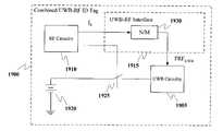
- a remote deviceconfigured to receive both RF and UWB transmissions. While several embodiments are disclosed herein, one embodiment would be to include RF circuitry to receive an RF signal, UWB circuitry to transmit a UWB signal, and a UWB-RF interface to facilitate communication between these two elements.
- UWB-RFultrawide bandwidth-radio frequency
- This combined UWB-RF remote identification tagmay further comprise: a power supply for providing power to the UWB circuitry; and a switch connected between the power supply and the UWB circuitry.
- the interface circuitrypreferably controls the operation of the switch based on a signal received from the RF circuitry.
- the UWB-RF interfacemay further comprise a first scaler for receiving a frequency signal from the RF circuitry, scaling it by a first scaling factor N/M, and providing a first scaled frequency to the UWB circuitry.
- N and Mare preferably integers.
- the combined UWB-RF remote identification tagmay further comprise: a power supply for providing power to the UWB circuitry; and a switch connected between the power supply and the UWB circuitry.
- the interface circuitrypreferably controls the operation of the switch based on a signal received from the RF circuitry.
- the scaled frequencyis preferably used by the UWB circuitry as a pulse repetition frequency.
- the UWB-RF interfacemay further comprise: a second scaler for receiving the frequency signal from the RF circuitry, scaling it by a second scaling factor P/Q, and providing a second scaled frequency to the UWB circuitry; a memory device for providing a data signal; and a mixer for mixing the second scaled frequency with the data signal to form a UWB radio frequency signal.
- P and Qare preferably integers.
- the UWB-RF interfacemay further comprise all of: a first scaler for receiving a frequency signal from the RF circuitry, scaling it by a first scaling factor N/M, and providing a first scaled frequency to the UWB circuitry; a second scaler for receiving the frequency signal from the RF circuitry, scaling it by a second scaling factor P/Q, and providing a second scaled frequency to the UWB circuitry; a memory device for providing a data signal; and a mixer for mixing the second scaled frequency with the data signal to form a UWB radio frequency signal, and providing the UWB radio frequency signal to the UWB circuitry.
- N, M, P and Qare all preferably integers.
- FIG. 1is a block diagram of an ultra-wide band (UWB) system according to a preferred embodiment of the present invention
- FIG. 2is a block diagram of an ultra-wide band (UWB) transceiver according to a preferred embodiment of the present invention
- FIG. 3illustrates a processor system according to a preferred embodiment of the present invention
- FIG. 4is a diagram depicting the interconnection of devices according to a preferred embodiment of the present invention.
- FIG. 5is a flow chart describing a process for communicating with remote wireless devices based on distance information according to a preferred embodiment of the present invention
- FIG. 6is a flow chart describing the process of establishing a link with remote devices using a multiple access protocol according to a preferred embodiment of the present invention
- FIG. 7is a flow chart describing the process of determining distance to a remote device according to a preferred embodiment of the present invention.
- FIGS. 8 and 9describe alternative processes for communicating with remote devices based on distance information in accordance with other preferred embodiments of the present invention.
- FIGS. 10 and 11describe an alternative process for communicating with remote devices based on distance information in accordance with other preferred embodiments of the present invention.
- FIG. 12describes a process for providing secured communications with remote devices according to a preferred embodiment of the present invention
- FIG. 13is a flow chart that describes an exemplary process for providing a secured communications link using public key cryptography in accordance with a preferred embodiment of the present invention
- FIG. 14is a block diagram of a remote device according to a preferred embodiment of the present invention.
- FIG. 15is a block diagram of a remote device according to another preferred embodiment of the present invention.
- FIG. 16is a block diagram of a remote device according to yet another preferred embodiment of the present invention.
- FIG. 17is a block diagram showing a combined UWB-RF tag according to a first preferred embodiment
- FIG. 18is a block diagram showing a combined UWB-RF tag according to a second preferred embodiment
- FIG. 19is a block diagram showing a combined UWB-RF tag according to a third preferred embodiment.
- FIG. 20is a block diagram showing a combined UWB-RF tag according to a fourth preferred embodiment
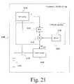
- FIG. 21is a block diagram showing a combined UWB-RF tag according to a fifth preferred embodiment
- FIG. 22is a block diagram showing a combined UWB-RF tag according to a sixth preferred embodiment
- FIGS. 23A to 23Care signal graphs showing an embodiment in which pulse position modulation (PPM) is used to make a UWB signal coherent with an RF signal; and
- PPMpulse position modulation
- FIGS. 24A to 24Care signal graphs showing an embodiment in which bi-phase modulation is used to make a UWB signal coherent with an RF signal.
- FIG. 1is a block diagram of an ultra-wide band (UWB) system according to a preferred embodiment of the present invention.
- the UWB system 100includes an antenna 105 , a switch 110 , an RF physical medium device (PMD) 120 , a digital PMD 130 , a physical (PHY) layer conversion protocol (PLCP) 140 , a media access controller (MAC) 150 , a host controller 160 , a MAC manager 170 , a PHY layer manager 175 , and an electronic device 180 .
- PMDphysical medium device
- PHYphysical layer conversion protocol
- MACmedia access controller
- the RF PMD 120further includes a receiver front end 122 , a demodulator 124 , a transmitter front end 126 , and a modulator 128
- the digital PMD 130further includes a receiver baseband 132 , a transmitter baseband 134 , and a timing controller 136
- the device 180may include an application layer 185 that allows the device to operate in connection with the host controller 160 and a user 190 .
- the antenna 105converts an incoming UWB electromagnetic waveform into an electrical signal (or optical signal) and provides this signal to the switch 110 .
- the switch 110is connected to the receiver front end 122 in the RF PMD 120 , which performs analog signal processing on the incoming signal.
- the receiver front end 122processes the electrical (or optical) signals so that the level of the signal and spectral components of the signal are suitable for processing in the demodulator 124 .
- This processingmay include spectral shaping, such as a matched filtering, partially matched filtering, simple roll-off, etc.
- the received signalis then passed from the receiver front end 122 through the demodulator 124 and the receiver baseband 132 for signal processing to extract the information from the incoming signal.
- the demodulator 124performs analog signal processing on the incoming RF signal, which is then converted (preferably by either the demodulator 124 or the receiver baseband 132 ) for digital processing by the receiver baseband 132 .
- Timing information from the incoming signalis received by the timing controller 136 and is sent back to timing generators in the demodulator 124 and the modulator 128 . (See FIG. 2 and related discussion.)
- the MAC 150serves as an interface between the UWB wireless communication functions implemented by both the RF PMD 120 and the digital PMD and the application layer 185 that uses the UWB communications channel for exchanging data with the device 180 .
- the MAC 150is preferably a processor-based unit that is implemented either with hard-wired logic, such as in one or more application specific integrated circuits (ASICs) or in one or more programmable processors.
- ASICsapplication specific integrated circuits
- the host controller 160operates as an interface between the MAC 150 and the device 180 , and provides instructions to the RF PMD 120 , the digital PMD 130 , the PLCP 140 and the MAC 150 through the MAC manager 170 and the PHY layer manager 175 .
- the host controller 160is shown as being separate from the device 180 . In alternate embodiments all or part of the host controller 160 can be placed in the device 180 .
- FIG. 2is a more detailed block diagram of the UWB transceiver of FIG. 1 .
- the UWB transceiverincludes an antenna 105 , a transmit/receive (T/R) switch 110 , a receiver front end 122 , a transmitter front end 126 , a demodulator 124 , a modulator 128 , and a digital PMD 130 .
- the demodulator 124includes a splitter 210 , a plurality of correlators 220 1 - 220 N , and a plurality of input timing generators 825 1 - 825 N .
- the modulator 128includes an output timing generator 205 0 , an encoder 225 , and a waveform generator 230 .
- the output timing generator 205 0 and the plurality of input timing generators 205 1 - 205 Nare formed together into a single timing generator module 205 .
- This embodimentallows multiple fingers (also called arms) to process the incoming signal at the same time, increasing the speed and efficiency of acquisition and tracking.
- the T/R switch 110connects the antenna 105 to either the receiver front end 122 , or the transmitter front end 126 , depending upon whether the transceiver is transmitting or receiving. In alternate embodiments separate transmitting and receiving antennas could be used.
- the received energyis coupled in to the T/R switch 110 , which passes the energy to the receiver front end 122 as an incoming signal.
- the receiver front end 122filters, extracts noise, and adjusts the amplitude of the incoming signal before providing the same to the splitter 210 in the demodulator 124 .
- the splitter 210divides the incoming signal up into N copies of the incoming signal and applies the N incoming signals to respective correlators 220 1 - 220 N .
- Each of the correlators 220 1 - 220 Nreceives a clock input signal from a respective input timing generator 205 1 - 205 N of the timing generator module 205 as shown in FIG. 2 .
- Each of these correlatorscorresponds to a different finger of the transceiver.
- the input timing generators 205 1 - 205 Nreceive a phase and frequency adjustment signal from the digital PMD 130 , but may also receive a fast modulation signal or other control signals as well.
- the digital PMD 130may also provide control signals (e.g., phase, frequency and fast modulation signals, etc.) to the timing generator module 205 for time synchronization and modulation control.
- the fast modulation control signalmay be used to implement, for example, chirp waveforms, PPM waveforms, such as fast time scale PPM waveforms, etc.
- the digital PMD 130may also provide control signals to, for example, the encoder 225 , the waveform generator 230 , and the transmitter front end 126 , the T/R switch 110 , the receiver front end 122 , the correlators 220 1 - 220 N , etc., for controlling, for example, amplifier gains, signal waveforms, filter passbands and notch functions, alternative demodulation and detecting processes, user codes, spreading codes, cover codes, etc.
- the digital PMD 130adjusts the phase input of the first input timing generator 205 1 , in an attempt for the first tracking correlator 220 1 to identify and the match the timing of the signal produced at the receiver with the timing of the arriving signal.
- the digital PMD 130senses the high signal strength or high SNR and begins to track, indicating that the receiver is synchronized with the received signal.
- the receiverwill operate in a track mode, where the first input timing generator 205 1 is adjusted by way of a continuing series of phase adjustments to counteract any differences in timing of the first input timing generator 205 1 and the incoming signal.
- a feature of the present inventionis that by sensing the mean of the phase adjustments over a known period of time, the digital PMD 130 adjusts the frequency of the first input timing generator 205 1 so that the mean of the phase adjustments becomes zero.
- the frequencyis adjusted in this instance because it is clear from the pattern of phase adjustments that there is a frequency offset between the first input timing generator 205 1 and the clocking of the received signal. Similar operations may be performed on the second through N th input timing generators 205 2 - 205 N , so that each finger of the receiver can recover the signal delayed by different amounts, such as the delays caused by multipath (i.e., scattering along different paths via reflecting off of local objects).
- a feature of the transceiver in FIG. 2is that it includes a plurality of tracking correlators 220 1 - 220 N .
- a plurality of correlatorsBy providing a plurality of correlators, several advantages are obtained. First, it is possible to achieve synchronization more quickly (i.e., by operating parallel sets of correlation arms to find strong SNR points over different code-wheel segments). Second, during a receive mode of operation, the multiple arms can resolve and lock onto different multipath components of a signal. Through coherent addition, the UWB communication system uses the energy from the different multipath signal components to reinforce the received signal, thereby improving signal to noise ratio. Third, by providing a plurality of tracking correlator arms, it is also possible to use one arm to continuously scan the channel for a better signal than is being received on other arms.
- the communications systemdynamically adapts to changing channel conditions.
- the digital PMD 130receives the information from the different correlators 220 1 - 220 N and decodes the data.
- the digital PMD 130also provides control signals for controlling the receiver front end 122 , e.g., such as gain, filter selection, filter adaptation, etc., and adjusting the synchronization and tracking operations by way of the timing generator module 205 .
- the digital PMD 130is connected to the PLCP 140 (not shown in FIG. 2 ), which serves as an interface between the communication link feature of the present invention and other higher level applications that will use the wireless UWB communication link for performing other functions.
- Some of these functionswould include, for example, performing range-finding operations, wireless telephony, file sharing, personal digital assistant (PDA) functions, embedded control functions, location-finding operations, etc.
- an output timing generator 205 0On the transmit portion of the transceiver shown in FIG. 2 , an output timing generator 205 0 also receives phase, frequency and/or fast modulation adjustment signals for use in encoding a UWB waveform from the digital PMD 130 . Data and user codes (via a control signal) are provided to the encoder 225 , which in the case of an embodiment of the present invention using time-modulation passes command signals (e.g., ⁇ t) to the output timing generator 205 0 for providing the time at which to send a pulse. In this way, encoding of the data into the transmitted waveform may be performed.
- command signalse.g., ⁇ t
- the encoder 225When the shape of the different pulses are modulated according to the data and/or codes, the encoder 225 produces the command signals as a way to select different shapes for generating particular waveforms in the waveform generator 230 .
- the datamay be grouped in multiple data bits per channel symbol.
- the waveform generator 230then produces the requested waveform at a particular time as indicated by the timing generator 205 0 .
- the output of the waveform generatoris then filtered and amplified as needed in the transmitter front end 126 before being transmitted from the antenna 105 by way of the T/R switch 110 .
- the transmit poweris set low enough that the transmitter and receiver are simply alternately powered down without need for the T/R switch 110 .
- no transmitter front end 126is needed because the desired power level and spectrum are directly useable from the waveform generator 230 .
- the transmitter front end 126may be included in the waveform generator 230 depending on the implementation of the present invention.
- a feature of the UWB communications system disclosedis that a transmitted waveform can be made to have a nearly continuous power flow, for example, by using a high chipping rate, where individual wavelets in the waveform are placed nearly back-to-back.
- This configurationallows the system to operate at low peak voltages, yet produce ample average transmit power to operate effectively.
- sub-micron geometry CMOS switchesfor example, running at one-volt levels, can be used to directly drive the antenna 105 such that no separate amplification is required in the transmitter front end 126 . In this way, the entire radio can be integrated on a single monolithic integrated circuit.
- the systemcan be operated without any filters in the transmitter front end 126 . If, however, the system is to be operated, for example, with another radio system, the transmitter front end 126 can be used to provide a notch function to limit interference with other radio systems. In this way, the system can operate simultaneously with other radio systems, providing advantages over conventional devices that use avalanching type devices connected straight to an antenna, such that it is difficult to include filters therein.
- FIG. 3illustrates a processor system 300 according to a preferred embodiment of the present invention.
- the processor system 300includes a processor unit 301 , a display 315 , one or more input devices 317 , a cursor control 319 , a printer 321 , a network link 323 , a communications network 325 , a host computer 327 , an Internet Protocol (IP) network 329 , and a mobile device 331 .
- the processor unit 301includes a bus 303 , a processor 305 , a main memory 307 , a read only memory (ROM) 309 , a storage device 311 , and a communication interface 313 . Alternate embodiments may omit various elements.
- the bus 303operates to communicate information throughout the processor unit. It is preferably a data bus or other communication mechanism for communicating information.
- the processor 305is coupled with the bus 303 and operates to process the information.
- the main memory 307may be a random access memory (RAM) or other dynamic storage device (e.g., dynamic RAM (DRAM), static RAM (SRAM), synchronous DRAM (SDRAM), flash RAM). It is preferably coupled to the bus 303 for storing information and instructions to be executed by the processor 305 . In addition, a main memory 307 may be used for storing temporary variables or other intermediate information during execution of instructions to be executed by the processor 305 .
- RAMrandom access memory
- DRAMdynamic RAM
- SRAMstatic RAM
- SDRAMsynchronous DRAM
- flash RAMflash RAM
- the ROM 309may be a simple read-only memory, or may be another kind of static storage device (e.g., programmable ROM (PROM), erasable PROM (EPROM), and electrically erasable PROM (EEPROM)). It is coupled to the bus 303 and stores static information and instructions for the processor 305 .
- PROMprogrammable ROM
- EPROMerasable PROM
- EEPROMelectrically erasable PROM
- the storage device 311may be a magnetic disk, an optical disc, or any other device suitable for storing data. It is provided and coupled to the bus 303 and stores information and instructions.
- the processor unit 301may also include special purpose logic devices (e.g., application specific integrated circuits (ASICs)) or configurable logic devices (e.g., simple programmable logic devices (SPLDs), complex programmable logic devices (CPLDs), or re-programmable field programmable gate arrays (FPGAs)).
- ASICsapplication specific integrated circuits
- SPLDssimple programmable logic devices
- CPLDscomplex programmable logic devices
- FPGAsre-programmable field programmable gate arrays
- Other removable media devicese.g., a compact disc, a tape, and a removable magneto-optical media
- fixed, high density media drivesmay be added to the processor unit 301 using an appropriate device bus (e.g., a small system interface (SCSI) bus, an enhanced integrated device electronics (IDE) bus, or an ultra-direct memory access (DMA) bus).
- the processor unit 301may additionally include a compact disc reader, a compact disc reader-writer unit, or a compact disc
- the processor system 301may be coupled via the bus 303 to the display 315 .
- the display unitmay be a cathode ray tube (CRT), a liquid crystal display (LCD), or any other suitable device for displaying information to a system user.
- a display or graphics cardmay control the display 315 .
- the processor system 301is also preferably connected to the one or more input devices 317 and a cursor control 319 for communicating information and command selections to the processor 305 .
- the one or more input devicesmay include a keyboard, keypad, or other device for transferring information and command selections.
- the cursor control 319may be a mouse, a trackball, cursor direction keys, or any suitable device for communicating direction information and command selections to the processor 305 and for controlling cursor movement on the display 315 .
- a printer 321may provide printed listings of the data structures or any other data stored and/or generated by the processor system 301 .
- the processor unit 301performs a portion of all of the processing steps of the invention in response to the processor 305 executing one or more sequences of one or more instructions contained in a memory, such as the main memory 307 .
- a memorysuch as the main memory 307 .
- Such instructionsmay be read into the main memory 307 from another computer-readable medium, such as a storage device 311 .
- processors in a multi-processing arrangementmay also be employed to execute the sequences of instructions contained in the main memory 307 .
- hard-wired circuitrymay be used in place of or in combination with software instructions. Thus, embodiments are not limited to any specific combination of hardware circuitry and software.
- the processor unit 301includes at least one computer readable medium or memory programmed according to the teachings of the invention and for containing data structures, tables, records, or other data described herein.
- the present inventionincludes software for controlling the system 301 , for driving a device or devices for implementing the invention, and for enabling the system 301 to interact with a human user.
- Such softwaremay include, but is not limited to, device drivers, operating systems, development tools, and applications software.
- Such computer readable mediafurther includes the computer program product of the present invention for performing all or a portion (if processing is distributed) of the processing performed in implementing the invention.
- the computer code devices of the present inventionmay be any interpreted or executable code mechanism, including but not limited to scripts, interpretable programs, dynamic link libraries, Java or other object oriented classes, and complete executable programs. Moreover, parts of the processing of the present invention may be distributed for better performance, reliability, and/or cost.
- Non-volatile mediaincludes, for example, optical, magnetic disks, and magneto-optical disks, such as the storage device 311 .
- Volatile mediaincludes dynamic memory, such as the main memory 307 .
- Transmission mediaincludes coaxial cables, copper wire and fiber optics, including the wires that comprise the bus 303 . Transmission media may also take the form of acoustic or light waves, such as those generated during radio wave and infrared data communications.
- Computer readable mediainclude, for example, hard disks, floppy disks, tape, magneto-optical disks, PROMs (EPROM, EEPROM, Flash EPROM), DRAM, SRAM, SDRAM, or any other magnetic medium, compact disks (e.g., CD-ROM), or any other optical medium, punch cards, paper tape, or other physical medium with patterns of holes, a carrier wave, carrierless transmissions, or any other medium from which a system can read.
- Various forms of computer readable mediamay be involved in providing one or more sequences of one or more instructions to the processor 305 for execution.
- the instructionsmay initially be carried on a magnetic disk of a remote computer.
- the remote computercan load the instructions for implementing all or a portion of the present invention remotely into a dynamic memory and send the instructions over a telephone line using a modem.
- a modem local to system 301may receive the data on the telephone line and use an infrared transmitter to convert the data to an infrared signal.
- An infrared detector coupled to the bus 303can receive the data carried in the infrared signal and place the data on the bus 303 .
- the bus, 303carries the data to the main memory 307 , from which the processor 305 retrieves and executes the instructions.
- the instructions received by the main memory 307may optionally be stored on a storage device 311 either before or after execution by the processor 305 .
- the communications interface 313provides a two-way UWB data communication coupling to a network link 323 , which is connected to the communications network 325 .
- the communications network 325may be a local area network (LAN), a personal area network (PAN), or the like.
- the communication interface 313may be a network interface card and the communications network may be a packet switched UWB-enabled PAN.
- the communication interface 313may be a UWB accessible asymmetrical digital subscriber line (ADSL) card, an integrated services digital network (ISDN) card, or a modem to provide a data communication connection to a corresponding type of communications line.
- ADSLasymmetrical digital subscriber line
- ISDNintegrated services digital network
- the communications interface 313may also include the hardware to provide a two-way wireless communications coupling other than a UWB coupling, or a hardwired coupling to the network link 323 .
- the communications interface 313may incorporate the UWB transceiver of FIG. 1 or FIG. 8 as part of a universal interface that includes hardwired and non-UWB wireless communications coupling to the network link 323 .
- the network link 323typically provides data communication through one or more networks to other data devices.
- the network link 323may provide a connection through a LAN to the host computer 327 or to data equipment operated by a service provider, which provides data communication services through the IP network 329 .
- the network link 323may provide a connection through the communications network 325 to the mobile device 331 , e.g., a personal data assistant (PDA), laptop computer, or cellular telephone.
- PDApersonal data assistant
- the communications network 325 and IP network 329both preferably use electrical, electromagnetic, or optical signals that carry digital data streams.
- the signals through the various networks and the signals on the network link 323 and through the communication interface 313 , which carry the digital data to and from the system 301 ,are exemplary forms of carrier waves transporting the information.
- the processor unit 301can transmit notifications and receive data, including program code, through the communications network 325 , the network link 323 , and the communication interface 313 .
- the present inventionuses the benefits offered by ultra wide band spread spectrum technology. From an energy spreading perspective, or from a resolution perspective, bandwidth and center frequency can be treated independently.
- the name UWBwas coined by a DARPA study panel and though the term “relative bandwidth” does not appear in the name, a definition of UWB demands use of this term.
- the motivations for preferring definitions based on bandwidth relative to center frequencyfollow from three primary desirable features.
- the firstis immunity to scintillation and multipath fading.
- the only way to prevent scintillation, speckle, and multipath fadingis to have resolution that is approximately equal to the wavelength.
- the secondis penetrating materials with high bandwidth signals.
- Bis the bandwidth
- f cis the center frequency
- f h and f lare the high and low frequency cutoffs (e.g. ⁇ 6 dB from peak)
- a UWB systemis one that has a fractional bandwidth, B f , in the range of 0.25 to 2.0, which means that a UWB system approximately matches its bandwidth to its center frequency. Said another way, this means that a UWB system matches resolution to wavelength.
- the present inventionprovides a system and method that enables device functions based on distance information. More specifically, the present invention allows a simplified method for enabling communications between a local wireless device and a remote wireless device based on the distance between the wireless devices.
- the wireless devices involvedIn order to provide such a distance-based system that is practically usable, the wireless devices involved must be able to discriminate distances at fine intervals; or stated another way, the wireless device must have accurate range resolution.
- the present inventorshave recognized that the range resolution of a receiver is roughly inverse to the bandwidth of the transmit signal. Therefore, narrowband systems having a bandwidth of 1 MHZ, such as the Bluetooth technology previously discussed, have a range resolution of
- a device implementing Bluetooth protocol even if configured to determine distancecan discriminate between remote devices based on distance only if the devices are 300 meters apart.
- wireless devices based on IEEE 802.11 A and B standardshave a bandwidth of 20 MHZ and a range resolution of 15 meters or approximately 45 feet. This resolution does not provide the ability to discriminate between remote devices using distance information that is needed for short range exchanges that are typical of wireless hand held devices such as the exchange of electronic business cards.
- a local UWB devicecan compute a unique distance to remote UWB devices as long as the actual distance from the local device to each remote device differs on the order of centimeters, which is a common scenario for current uses of wireless devices such as PDAs.
- FIG. 4discloses a wireless network 400 in which a plurality of wireless devices may exchange information.
- the wireless network 400may be WPAN, WLAN, or some other wireless network in which wireless devices make point-to-point connections, or point-to-multipoint connections on the shared channel of a piconet.
- the wireless network 400includes a local device 405 and first through N th remote devices 410 1 - 410 N .
- the local device 405is linked to the first through N th remote devices 410 1 - 410 N via UWB links 415 1 - 415 N , respectively.
- the UWB linksare preferably full duplex communications links that carry data, voice, video, or any other analog or digital information in accordance with the present invention. However, simplex communications in either direction may be used in alternate embodiments.
- Each of the wireless devices 405 and 410 1 through 410 Nmay be a mobile device such as a mobile telephone, a laptop computer or personal digital assistant (PDA), or a fixed structure device such as a retail store kiosk or some other fixed structure device for delivering information to other wireless devices.
- PDApersonal digital assistant
- device 405is referred to as a “local device” and devices 410 1 through 410 N are referred to as “remote devices” for purposes of description only, and that the present invention is not limited to an infrastructure system having an access point and may be implemented in an ad hoc system wherein any device in the network can act as a master and/or a slave device and no access point is needed.
- Each of the of the devices 405 and 410 1 through 410 Nincludes a processor system, such as the one described in FIG. 3 , for inputting, storing, and processing data in accordance with the present invention. Therefore, local device 405 and each remote device 410 1 through 410 N also includes a UWB transceiver, such as the transceiver described in FIGS. 1 and 2 , that transmits and receives a UWB signal 420 via a UWB antenna such as the antennas 105 described in FIGS. 1 and 2 .
- the UWB antenna 105is preferably an antenna as described in the patent application entitled ELECTRICALLY SMALL PLANAR UWB ANTENNA (Attorney Docket 10188-0005-8), or application Ser. No. 09/563,292, filed May 3, 2000 entitled PLANAR UWB ANTENNA WITH INTEGRATED TRANSMITTER AND RECEIVER CIRCUITS (Attorney Docket 10188-0006-8) referenced above and incorporated herein by reference, but may be any known UWB antenna.
- the UWB signal 420includes data for communicating with remote devices based on distance in accordance with the present invention.
- FIG. 5is a general flow chart that describes a process for enabling device functions based on distance information in accordance with the present invention.
- the processstarts when a device is turned on or enters the listening range of other wireless devices communicating on a wireless network.
- the local device 405establishes a link with each remote device 410 1 through 410 N using a multiple access protocol. Examples of multiple access protocols may be found in the IEEE 802.11 standard, final draft approved Jun. 26, 1997, and the Bluetooth specification “Specification of the Bluetooth System”, V.1.OB, Dec. 1, 1999, core specification—Vol. 1, the entire contents of which are incorporated herein by reference.
- the multiple access protocolprovides the capability for the local device 405 to establish unique and independent UWB links 415 1 , 415 2 , . . . , 415 N with remote devices 410 1 , 410 2 , . . . , 410 N respectively as will be discussed with respect to the exemplary protocol of FIG. 6 .
- the local device 405determines a distance to each linked remote device as shown in step 503 . In determining the distance, local device 405 exchanges data with remote devices 410 1 , 410 2 , . . . 410 N via their respective unique links. Each distance determined by the local device 405 is associated with the unique link on which the distance determining information was exchanged in order to associate a determined distance with a remote device as will be discussed below with reference to FIG. 7 .
- the local device 405then enables communications with each remote device in step 505 based on the distances determined in step 503 . Due to the range resolution of the UWB system included in each of the devices of FIG. 4 , the distance determined may be accurate on the order of centimeters, as discussed above. Therefore the probability of having remote devices at equal distances is very low and the local device 405 can differentiate between remote devices 410 1 , 410 2 , . . . , 410 N based on the distance determined for each device. For example, the local device may automatically enable data communications with devices that are within a predefined range at any given time while all remote devices outside the predefined range will be blocked from data communications with the local device as will be described below with respect to FIG. 8 .
- the local devicemay enable data communications with devices, that enter a predefined authentication range and maintain data communications with such devices until the user of the local device decides to terminate data communications with an authenticated remote device as will be described below with respect to FIG. 10 .
- a local devicemay display a positional map of all users in relation to the local device so that the user of the local device may select those remote devices that the user wants to communicate with as will be discussed below with respect to FIGS. 11 and 12 .
- the local device 405may store data sent from remote devices within a predefined range while only displaying the information sent from remote devices outside that range.
- the local device 405may notify the device user or automatically enter a sleep mode if no remote devices are within a predefined range.
- the local device 405in addition to determining the distance to remote devices 410 1 through 410 N and enabling communications based on the distance determined, the local device 405 updates distance information by way of a loop 507 .
- the loop 507returns to step 503 (determining distance for the remote devices) and may be performed only on devices that have been blocked from communicating with the local device 405 , or on both enabled and blocked remote devices.
- step 509the local device 405 periodically updates its links to the remote devices 410 1 through 410 N . In doing so, another loop 511 is established, which returns to step 501 (establishing a unique link with remote devices). In executing loop 511 , the local device 405 determines if remote devices that were previously linked to are no longer available, and whether new devices have entered the listening range of the local device 405 . Unique communications links are then destroyed or created in step 509 depending on the information obtained by executing the loop 511 .
- the process of enabling device functions and/or communicating with remote wireless devicesends when power to the local device 405 is turned off or the local device is outside the communicating area of the remote devices 410 1 through 410 N . While “end” is shown as proceeding from step 509 in FIG. 5 , it is to be understood that the end may occur at any point in the process of FIG. 5 .
- FIG. 6is a flow chart describing the process whereby the local device 405 establishes unique communication links 415 1 , 415 2 , . . . , 415 N with remote devices 410 1 , 410 2 , . . . , 410 N , respectively by using an exemplary multiple access protocol in accordance with the present invention.
- the local device 405transmits a join message to all unlinked remote devices within a range of the transmission power of the local device 405 .
- the join messagemay be a simple UWB signal that enables unlinked remote devices to synchronize to the local device 405 , or may include information such as a device identifier, a device type identifier, a standard bit code, and/or any other information desired to be transmitted from local device 405 to the unlinked remote devices 410 1 through 410 N .
- the join messageis transmitted only to unlinked remote devices and not over the unique links of synchronized remote devices, so that the local device 405 may form unique links with new remote devices entering step 601 (as indicated by loop 511 ) in FIG. 6 .
- each remote device that is listeningthen receives the join message and synchronizes with the local device 405 .
- each of the remote devices 410 1 through 410 Naligns in time a particular pulse sequence produced in the remote device with the pulse sequence of the joint signal sent from the local device.
- This synchronization of the remote devices 410 1 through 410 Nis preferably performed in accordance with the process described in any one of the following patent applications: Ser. No. 09/685,195, for “ULTRAWIDE BANDWIDTH SYSTEM AND METHOD FOR FAST SYNCHRONIZATION,” filed Oct. 10, 2000, Ser. No.
- each remote devicetransmits a reply to the join signal as shown in step 605 .
- Each replyis a UWB signal that includes a unique identifier associated with the remote device from which the reply is transmitted.
- the unique identifiermay be a device address stored in ROM 309 (see FIG. 3 ), for example, or a unique delay time for the remote device as will be described below.
- each of the remote devices 410 1 through 410 Nencodes its unique identifier information and attaches the information to a reply signal to be transmitted back to the local device 405 .
- the local device 405receives each reply and synchronizes with each remote device that sent a reply.
- the local device 405decodes each unique identifier and establishes unique communications links 415 1 , 415 2 , . . . , 415 N with remote devices 410 1 , 410 2 , . . . , 410 N , respectively.
- the local device 405associates the unique identifier of each remote device with a communications link established by the synchronization process for the particular remote device.
- the unique identifier and associated linksare then stored to the main memory 307 (See FIG. 3 ) of the local device 405 for use in determining distance as will be described below.
- Each unique link 415 1 , 415 2 , . . . , 415 Nis preferably a low-level communications link that is allocated a minimal amount of bandwidth available to the local device 405 .
- the amount of bandwidth allocatedmay vary but is preferably an amount that is sufficient for the local device 405 to maintain awareness of the presence of the remote devices 410 1 through 410 N and to determine distance to each remote device.
- FIG. 7describes a process of determining distance to each linked remote device in accordance with an embodiment of the present invention.
- a distance-determining messageis generated in the local device 405 and transmitted to each linked remote device 410 1 , 410 2 , . . . , 410 N via the unique communication links 415 1 , 415 2 , . . . , 415 N .
- the distance determining messageis a simple UWB signal the acts as a notification and/or request to each remote device that a distance determination is being made by the local device 405 .
- the distance determining messagemay be attached to a communication for a particular link as indicated by input 507 and as will be described with respect to FIG. 8 .
- the local device 405For each distance determining message sent on each unique communications link 410 1 through 410 N , the local device 405 marks a time t 1 as the transmitting time that the message was sent out for the particular communications link as shown in step 703 . Transmit time t 1 is obtained by a system clock in the processor system 301 of the local device 405 . Each transmit time t 1 is associated with one of the unique identifiers stored in step 609 based on the unique link over which the distance determining massage was transmitted. The transmit times and associated identifiers are then stored in the main memory 307 of local device 405 so that the transmit times may be retrieved to determine the distance to each remote device.
- the linked remote devices 410 1 , 410 2 , . . . , 410 Nreceive the distance-determining message via a respective unique link and transmit a response to the local device 405 over the same unique link.
- the response message from the remote devicesmay include a communication if the link responded on is an enabled link.
- step 707the local device 405 receives responses sent from the linked remote devices via respective unique links and marks a receive time t 2 for each response received as seen in step 709 .
- each receive time t 2is associated with the unique identifier of a respective link and stored in main memory 307 for use in calculating a distance from the local device 405 to each remote device 410 1 through 410 N .
- the local device 405Before computing a distance to each linked remote device, the local device 405 first determines a processing delay d for each linked remote device as seen in step 711 .
- the processing delay dis the time delay between the remote device receiving the distance determining message and transmitting a response and includes at least the amount of time necessary for the remote device to process the distance determining message and form a response.
- the processing delay dis determined by retrieving the delay from the memory of the local device 405 .
- the local device 405receives information from each remote device about the radio type of the remote device, as part of the reply and/or response received from the remote devices as discussed with respect to steps 607 and 707 respectively.
- the type informationmay be received as part of an independent signal sent by the remote devices.
- the local device 405then refers to a look up table (LUT) stored in memory 307 or ROM 309 (See FIG. 3 ) to determine a predefined processing delay for the radio type.
- LUTlook up table
- the processing delay d of each remote device 410 1 through 410 Nmay be transmitted to the local device 405 as part of the reply, the response, or some independent signal.
- the processing delay dmay be the inherent delay of the remote device plus some arbitrary delay time that gives the remote device a unique delay time the may be used as the unique identifier for the remote device as discussed with respect to step 605 of FIG. 6 above.
- the processing delay dis then stored in main memory 307 for use in establishing unique communications links with remote devices and in determining the distance to remote devices.
- the local device 405calculates the round trip time T rt for each linked remote device 410 1 through 410 N .
- the,local device 405retrieves the transmitting time t 1 , receiving time t 2 , and processing delay time d of a particular unique link to a remote device from main memory 307 and ROM 309 as discussed above.
- the round trip timeis the time that the distance determining signal and the response signal travel through the wireless medium and is different for each remote device.
- Each round trip time T rtis stored to main memory 307 where the processor 305 of the local device 405 retrieves values for T rt and computes the distance D to each remote device according to the following formula:
- cis the speed of light (i.e., the speed at which an RF signal travels through the wireless medium).
- the distance D for each remote device 410 1 through 410 Nis then associated with the unique identifier of the unique communications link over which the distance was determined and is stored in main memory 307 so that systems software of the local device 405 may retrieve the distance information to enable or block communications with the remote devices based on their distance from the local device 405 .
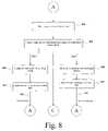
- FIG. 8is a flow chart describing the process of automatically enabling or blocking communications with each linked remote device 410 1 through 410 N based on the distance determined in accordance with an embodiment of the present invention.
- the local device 405obtains a range criteria r input to the local device.
- the range criteria ris a predefined distance that serves as a benchmark for enabling communications features of the local device 405 based on distance information.
- the range criteria ris preferably programmable by the user in which case the user inputs the range criteria into the main memory 307 of the local device 405 via the input device 315 for example, but may be set by the manufacturer of the local device in which case the range criteria is stored in the ROM 309 of the local device 405 .
- step 803the range criteria r is compared with the distance D determined for each remote device and stored in main memory 307 as discussed with respect to step 715 above. In making this comparison, the processor 305 determines whether the distance D for a particular remote device is less than, equal, or greater than the range criteria r.
- the local devicedetermines that the remote device is out of range and, according to the embodiment of FIG. 8 , blocks communications with the out of range remote device as shown in step 805 .
- the local device 405enables communications over links 415 1 and 415 2 and blocks data communications over link 415 N .
- a communicationis data, voice, video, or any other analog or digital information sent or received by the user of the local device 405 to or from remote device in accordance with the present invention.
- communicationsare blocked and enabled at the applications software level of the local device 405 . That is, communications transmitted to remote devices are prevented from being sent to the out of range remote devices ( 410 N in the above example) by the application software sending a command message to the MAC layer of the local device 405 indicating that a particular message should be transmitted on links 415 1 and 415 2 , but not on links 415 N .
- the applications softwaredisplays the communications received on links 415 1 and 415 2 to the user, but does not display the communications received on links 415 N .
- communications to and from the out of range remote device 400 Nmay be blocked at the MAC layer in the stack of the local device 405 .
- the local device 405allocates a minimal amount of available bandwidth to the link 415 N associated with the out-of-range device 400 N , and a relatively large amount of bandwidth to enabled links associated with in-range remote devices 410 1 and 410 2 .
- a communication sent to remote devices 410 1 and 410 2 via links 415 1 and 415 2will not be sent on the blocked communications link.
- a communication received from the out-of-range remote device 410 Nwill not be decoded and processed by the local device 405 .
- the received communications from out of range devicesis never processed and propagated up the stack of the local device 405 resulting in a more efficient system.
- the minimal bandwidth allocated to each of the out of range device 410 Nis sufficient to update the distance information so that the local device 405 can continue monitoring the distance of the out of range remote device 410 N as seen in step 807 .
- a new distance-determining signalis sent to the blocked remote device 410 N via link 415 N in accordance with the loop 507 as discussed in FIGS. 5 and 7 . Therefore, the distance from the local device 405 to the out of range remote device 410 N is again determined by transmitting a distance determining signal in accordance with the process of FIG. 7 .
- the remote device 410 NBecause the remote device 410 N is out of range, however, no communications are attached to the distance determining signal as indicated in FIG. 8 . If on the next distance determining message the distance to the remote device 410 N has changed due to movement of the remote device 410 N or the local device 405 , then the local device 405 enables communications with the remote device 410 N , if the new distances are less than or equal to the range criteria as seen in step 809 . This operation is performed as necessary for each of the remote devices 410 1 , 410 2 , . . . , 410 N that are out of range.
- the local device 405In enabling communications in step 809 , the local device 405 allocates a large amount of the available bandwidth to the communications links 415 1 and 415 2 associated with the remote devices 410 1 and 410 2 so that communications can be transmitted or received over these links as discussed above. In addition to transmitting and receiving communications on the enabled links, the local device also updates distance information for the enabled remote devices 410 1 and 410 2 as shown in step 811 .
- a new distance-determining signalis sent to the enabled remote devices 410 1 and 410 2 via links 415 1 and 415 2 , respectively in accordance with the loop 507 . Therefore, the distance from the local device 405 to the in range remote devices 410 1 and 410 2 is again determined by transmitting a distance determining signal in accordance with the process of FIG. 7 .
- communicationsmay be attached to the distance-determining signal as indicated in FIG. 8 . If on the next distance determining message the distance to the remote devices 410 1 and 410 2 have become greater than the range criteria, then the remote devices are determined to now be out of range and the local device 405 blocks communications as seen in step 805 .
- the local device 405continually updates link information as shown by connector C in FIG. 8 .
- the local device 405may be programmed to only allow a limited number of remote devices to link up with the local device 405 .
- limitation of linked deviceprevents a slowdown of communications to enabled devices. Therefore, the local device 405 keeps a network count of the remote devices that are linked with the local device 405 .
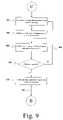
- FIG. 9describes the process for updating the communications links of the network 400 based on the network count in accordance with the present invention.
- the local device 405determines whether any of remote devices 410 1 , 410 2 , . . . , 410 N have exited the network 400 due to the user of the device turning off power to the remote device, or exiting the area in which the remote device can receive the transmit power of the local device and/or exiting the area in which the local device can receive the transmit power of the remote device. This determination may be made based on synchronization information with the remote devices or based on an exit signal transmitted from the remote device to the local device 405 .
- the local device 405updates a count of remote devices on the wireless network 400 based on the determination made in step 901 . If no linked remote devices have exited the network, the count remains the same, and the network count is decremented for each remote device that has left the network.
- step 905the local device 405 determines if a new remote device has attempted to enter the network 400 . This determination is made based on the unique identifiers received in the replies obtained from remote devices as discussed in FIG. 6 . If a new unique identifier is found that is not linked with the local device 405 , the local device determines if the network count is at maximum capacity as seen by decision block 907 . If the network count is at maximum capacity, the local device 405 returns to step 901 of determining whether a remote device has exited the network 400 as seen by loop 909 .
- Local device 405continues in loop 909 without sending a new join message to unlinked devices until the network count is less than the maximum capacity at which time the local device will increment the network counter in accordance with the number of new remote devices that have attempted to enter the network as seen in step, 911 .
- the local deviceexecutes loop 511 whereby a new join code is sent out to remote devices so that new remote devices may be able to join the network 400 as discussed in FIG. 5 .
- the local device 405automatically enables and blocks data communications with remote devices 410 1 , 410 2 , . . . , 410 N based on the distance to each remote device 410 1 , 410 2 , . . . , 410 N .
- the network established according to this embodimentis a dynamic network in which communications with remote devices may be enabled with the local device 405 based on their distance to the local device 405 without the need for the user of the local device 405 to select from among a list of remote devices 410 1 , 410 2 , . . . , 410 N as discussed in the background section above.
- the alternative embodiment of the present invention disclosed in FIG. 10describes a process for authenticating communications with linked remote devices based on distance information.
- the local device 405obtains an authentication range a of the local device.
- the authentication range ais preferably programmable by the user in which case the user inputs the authentication range into the main memory 307 of the local device 405 via the input device 315 for example, but may be set by the manufacturer of the device in which case the authentication range, is stored in the ROM 309 of the local device 405 .
- the authentication range aserves to enable, or authenticate, communications with remote devices 410 1 , 410 2 , . . . , 410 N regardless of the distance of the authenticated remote device thereafter as will be described below.
- step 1003the authentication range a is compared with the distance D determined for each remote device 410 1 , 410 2 , . . . , 410 N and stored in main memory 307 as discussed with respect to step 715 above.
- the processor 305determines whether the distance D for a particular remote device 410 1 , 410 2 , . . . , or 410 N is less than, equal, or greater than the authentication range a.
- the local device 405determines whether to authenticate remote devices 410 1 , 410 2 , . . . , 410 N based on the comparison made in step 1003 of FIG. 10 . If the results of the comparison indicate that the distance to the particular remote device 410 1 , 410 2 , . . . , or 410 N is greater that the authentication range (i.e., D>a), the local device determines that the remote device 410 1 , 410 2 , . . . , or 410 N cannot be authenticated and, according to the embodiment of FIG. 10 , blocks communications with the non-authenticated remote device 410 1 , 410 2 , . . . , or 410 N as shown in step 1007 .
- the results of the comparisonindicate that the distance to a particular remote device 410 1 , 410 2 , . . . , or 410 N is less than or equal to the authentication range (i.e., D ⁇ a), according to the embodiment of FIG. 10 , communications are enabled with the authenticated remote device as shown in step 1011 .
- the authentication range a of the local device 405is set to be 1 foot, and at any time the first remote device 410 1 enters within that distance to the local device 405 , communications with first remote device 410 1 will be enabled regardless of the distance of the first remote device 410 1 thereafter.
- the second remote device 410 2never enters within 1 foot of the local device 405 , the link 415 2 associated with the second remote device 410 2 will never get enabled.
- the local device 405updates distance information for non-authenticated remote devices in step 1009 , and if the non-authenticated device, for example the second remote device 410 2 as indicated above, enters the authentication range of the local device 405 , then the device is authenticated and the second communications link 415 2 associated with the second remote device 410 2 is enabled for transmitting and receiving communications.
- the non-authenticated devicefor example the second remote device 410 2 as indicated above, enters the authentication range of the local device 405 , then the device is authenticated and the second communications link 415 2 associated with the second remote device 410 2 is enabled for transmitting and receiving communications.
- distance informationis not updated for authenticated devices as indicated by the connection C in FIG. 10 . Rather, once a remote device 410 1 , 410 2 , . . . , or 410 N is authenticated by entering within the authentication range of the local device 405 , then the remote device 410 1 , 410 2 , . . . , or 410 N is enabled regardless of the distance from the local device 405 . Thus in the example discussed above, no distance information will be updated for the authenticated first remote device 410 1 until the user decides to terminate the authentication of the first remote device 410 1 . This allows a greater amount of bandwidth to be used for communications to authenticated remote devices 410 1 , 410 2 , . . . , 410 N .
- the local remote device 405authenticates communications based on the distance to each remote device 410 1 , 410 2 , . . . , 410 N .
- the local device 405enables communications with a remote device that enters an authentication range of the local device 405 and continually updates distance information for all non-authenticated remote devices 410 1 , 410 2 , . . . , 410 N while also searching for new remote devices 410 1 , 410 2 , . . . , 410 N to join the network
- the network established according to this embodimentis a dynamic network in which communications with remote devices 410 1 , 410 2 , .
- 410 Nmay be enabled with the local device 405 based on their distance to the local device 405 without the need for the user of the local device 405 to select from among a list of remote devices 410 1 , 410 2 , . . . , 410 N as discussed in the background section above.
- distance informationis used to provide a positional map of remote devices 410 1 , 410 2 , . . . , 410 N from which the user of the local device 405 can select the remote devices 410 1 , 410 2 , . . . , 410 N for which communications links will be enabled.
- FIG. 11shows a typical conference room 1100 located adjacent to rooms 1200 and 1300 .
- the conference room 1100has ten mobile wireless devices each of which is represented by an “X”, and four fixed reference devices represented by an “R”.
- a local mobile device within conference room 1100is represented as a bold faced X 1001 while all remote mobile devices within conference room 1100 are represented as a non-bolded X and mobile devices within adjacent rooms 1200 and 1300 are represented by a “Y”.
- the reference devices R 1 , R 2 , R 3 , and R 4are in fixed positions to provide a known reference point from which the position of each mobile device X and Y is measured.
- the reference devicesmay be fixed structure devices or mobile devices that remain stationary in conference room 1100 during conferences.
- local device 1101is referred to as a “local device” and all other devices of FIG. 11 are referred to as “remote devices”, this nomenclature is for purposes of description only and it is to be understood that the embodiment shown in FIG. 11 is not limited to an access point system and may be implemented in an ad hoc system wherein any device in the network can act as a master and/or a slave device.
- local device 1101 and each remote device X, Y and Rpreferably includes a processor system, such as the one described in FIG. 3 , for inputting, storing, and processing data in accordance with the present invention and a UWB transceiver that transmits and receives a UWB signal which includes data for communicating with remote devices based on distance in accordance with the present invention.
- each wireless device shown in FIG. 11preferably includes some sort of a compass for orienting the display 313 of the local device 1101 .
- the reference devices R 1 , R 2 , R 3 , and R 4are preferably located due north, south east and west and west of a center point of the conference room 1100 , as seen by the directional arrows of FIG. 11 , so that the display 313 of the local device 1101 can be oriented in accordance with the direction in which the user of the local device is facing as will be discussed.
- the display 313 of the processor system 301 of local device 1101displays a graphical map of the position of each remote device in conference room 1100 from which the user of the local device may choose remote devices to enable communications with.
- the display 313appears as a top view of the conference room 1100 with each device physically located in the conference room having a corresponding position on the display 313 of the local device 1101 .
- the user of local device 1101looks at the display 313 and associates the devices on the display with remote device users visually verified by the local user.
- the reference marker that the local user is facingalways appears at the top of the display 313 so that the local user can easily associate the physical location of a device with the corresponding screen location.
- FIG. 12shows a process for enabling and disabling communication with remote devices based on selections made on a positional map obtained from distance information in accordance with the present invention.
- the local device 1101establishes a unique link with each remote device, including mobile devices X, reference devices R 1 -R 4 , and mobile devices Y as described in FIG. 6 , and determines distance to each remote device as described in FIG. 7 .
- the local device 1101transmits a position-determining message to all linked remote devices X, R, and Y via the unique links established with each device.
- the position-determining messagemay be a simple UWB signal that indicates that the local device 1101 is requesting the data necessary to determine position information from each linked remote device.
- the position determining messagemay be included in a communication to devices previously enabled by the local device 1101 .
- each of the linked remote devicesreceives the position-determining message and transmits an answer to the local device 1101 via a respective communication link.
- each of the linked remote devicesencodes position information obtained by the remote device and includes the position information in the answer transmitted.
- the position informationincludes the distance from the answering remote device to each other remote device X, R, and Y.
- mobile device 1103will have a continually updated database of the distance from itself to reference device R 1 , to reference device R 3 , to device 1105 , and each other device as indicated by dashed lines D 1 -D 4 of FIG. 11 .
- device 1105will have a continually updated database of the distance from itself to each other device as shown by dashed lines D a -D c of FIG. 11 .
- devices 1103 and 1105encode this position information and transmit it as part of the answer to local device 1101 .
- the position informationmay include distance from the answering remote device to a limited number of remote devices when the number of remote devices in the listening range of the local device 1101 is large.
- remote devicesmay cooperate with one another to ensure that duplicate distance information (such as distance D 3 and D b ) is not transmitted to local device 1101 more than once.
- the answer of the reference devices R 1 through R 4includes data identifying the reference device as a reference device as well as the unique position of the reference device.
- reference device R 1 of FIG. 11would encode data indicating that the position of R 1 is on the north wall of the conference room 1100 .
- this informationis input into the reference devices R 1 -R 4 by a user when the conference room 1100 is set up for positional capabilities. This data allows a particular reference device to be placed at the top of the display 313 when a compass of the local device indicates that the local user is facing the reference device as will be discussed.
- the local device 1101receives the answer from each remote device including the reference devices R 1 -R 4 , devices X and devices Y, and decodes the positional information of each remote device and stores the distances of the positional information in main memory 307 . From the stored distance information, processor 305 of device 1101 determines the position of each device using a triangulation process as seen in step 1207 . All positions are then displayed on the display 313 of the local device 1101 so that the user of the local device can associate each remote device on the screen with a remote device physically located in the conference room 1100 .
- the local device 1101uses triangulation information to determine which remote devices are outside a boundary formed by reference devices R 1 -R 4 and uses this information to display only those devices within the boundary.
- the local device 1101identifies the remote devices Y located in rooms 1200 and 1300 of FIG. 11 and does not display these devices on the display 313 of the local device 1101 .
- the userWith the remote devices located within conference room 1100 displayed on the display 313 of the local device 1101 , the user enables communications with a remote device viewed in physical space of the conference room 1100 by selecting a corresponding position on the display in order to, as shown in step 1209 .
- the display 313has touch screen capabilities that allow the user to select a remote device by contacting the display with a pointing device, for example. If the user of the local device 1101 selects a position located on the display of the local device, then the local device 1001 enables communications with that device as shown in step 1215 .
- positional information on enabled linksis updated as shown in step 1217 and loop 507 of FIG. 12 . If the user does not select a position on the display screen, the communications link associated with the unselected device is blocked from data communications as in step 1211 and positional information for blocked links is updated in step 1213 . Also, as with other embodiments, the local device 1101 periodically looks for new devices and updates communications links as shown by connection C FIG. 12 .
- display 313indicates which remote devices are enabled as positional information is updated in steps 1213 and 1217 .
- remote devices for which communications are enabledmay be indicated by circling the remote devices.
- the user of local device 1101can keep track of which devices communications are enabled for by viewing the circled Xs on display 313 .
- the local device 1101displays a graphical map of the position of remote devices in relation to the local device and enables communications based on local user's selection of a remote device on the map.
- the positionsare determined based on positional data that includes distances between the remote devices, devices may be enabled with the local device based on their distance to the local device 1101 without the need for the user of the local device 1101 selecting from among a list of remote devices as discussed in the background section above.
- communications links enabled by any of the processes describedmay be a secure communications using encryption methods such as the methods described in the text entitled HOW THE INTERNET WORKS, Millennium Edition, Preston Gralla, Macmillan Computer Publishing, Indianapolis 1999, the contents of which are incorporated by reference in their entirety.
- FIG. 13describes an exemplary process for providing a secured communications link using public key cryptography in accordance with a preferred embodiment of the present invention.
- the local device 1001transmits a request for secured communications to enabled remote devices.
- the requestincludes public key of the local device requesting the secured communications.
- the public keyis a key that is shared with any remote device and is used by the remote device to encrypt a data communication intended for the local device.
- the enabled remote devicesreceive the request for secured communications and the public key of the local device. Each enabled remote device then decodes the public key in step 1305 and uses the public key to encrypt any message that the remote device intends for the local device in step 1307 . As seen in step 1307 , encryption is accomplished by applying the public key of the local device and the message to any one of a variety of known encryption algorithms. The encrypted message is then transmitted from the enabled remote device to the local device.
- the local devicereceives the encrypted message that is unintelligible. Any device that may intercept the encrypted message will not be able to decrypt the message even if the intercepting device has the public key of the local device because a private key that only the local device has is needed to decrypt the unintelligible message.
- step 1309the local device obtains its private key from memory and decrypts the encrypted message using the private key.
- secure communicationscan be provided for any one of the discussed embodiments for enabling communications based on distance information described above.
- methods of guaranteeing the source of a particular messagesuch as digital certificates and other means of authentication may also be applied to the present invention.
- FIGS. 14 to 16show the remote devices 410 1 , . . . , 410 N according to preferred embodiments of the present invention.
- FIG. 14shows a UWB tag 1400 configured as a transmitter
- FIG. 15shows a UWB tag 1500 configured as a receiver
- FIG. 16shows a UWB tag 1600 configured as a transceiver.
- the UWB tag 1400 used for transmittingincludes an antenna 1405 , a physical layer (PHY) 1410 , a media access controller (MAC) 1415 , a memory 1420 , a host controller interface (HCI) 1425 , and a power supply 1430 .
- PHYphysical layer
- MACmedia access controller
- HCIhost controller interface
- the various elementsoperate as follows.
- the antenna 1405transmits a UWB signal as provided to it from the PHY 1410 , which prepares the signal for transmission in a manner similar to that disclosed above for the RF PMD 120 and the digital PMD 130 shown in FIG. 1 .
- the PHY 1410can be reduced in complication as compared to the RF PMD 120 and the digital PMD 130 by eliminating all circuitry relating to receiving functions.
- the PHY 1410may be further simplified such that it only supports that limited type of signal.
- the MAC 1415serves as the interface between the UWB wireless communication functions implemented by the PHY 1410 and the data contained in the memory 1420 .
- the MAC 1415essentially translates the data stored in the memory 1420 into a format that the PHY 1410 can transmit via the antenna 1405 .
- Given the limited functions that must be performed by the MAC 1415it is significantly reduced in complexity as compared to the MAC 150 shown in FIG. 1 .
- the MAC 1415could be eliminated altogether and the memory 1420 could be loaded with data already in the proper form for the PHY 1410 to use.
- the memory 1420holds the information that will be transmitted by the UWB tag 1400 .
- itmay include tag ID data, date of placement of the tag, information about what the tag is associated with (person, product, shipment, etc.), or any other desirable information.
- memory 1420is a static memory device, such as an EPROM, EEPROM, etc.
- the HCI 1425serves as an interface for providing data to the memory 1420 from an external source. It could connect to a bar code reader if the tag 1400 includes simple identification information, a computer output if it receives more complicated information, an internal processor if the tag 1400 is contiguous with a remote device such as a PDA, etc.
- the memory 1420may be a read-only memory and the HCI 1425 may be eliminated.
- the power supply 1430provides the necessary power required to operate the elements of the UWB tag 1400 . It is preferably a battery power source that is configured in a fashion to extend its lifetime as long as possible. However, alternate sources may be used provided they could meet power and functional lifetime requirements.
- the UWB tag 1500 for receivingincludes an antenna 1405 , a physical layer (PHY) 1510 , a media access controller (MAC) 1515 , a memory 1520 , a host controller interface (HCI) 1525 , and a power supply 1430 .
- PHYphysical layer
- MACmedia access controller
- HCIhost controller interface
- the various elementsoperate as follows.
- the antenna 1405receives a UWB signal, transforms it into an electrical or optical signal, and as provides to it from the PHY 1510 , which demodulates the signal and extracts the data from it in a manner similar to that disclosed above for the RF PMD 120 and the digital PMD 130 shown in FIG. 1 .
- the PHY 1510can be reduced in complication as compared to the RF PMD 120 and the digital PMD 130 by eliminating all circuitry relating to transmitting functions.
- the PHY 1510may be further simplified such that it only supports that limited type of signal.
- the MAC 1515serves as the interface between the UWB wireless communication functions implemented by the PHY 1410 and the data used by the memory 1520 and HCI 1525 .
- the MAC 1515essentially translates the data received from the PHY 1510 into a format that the memory 1520 or HCI 1525 can use. Given the limited functions that must be performed by the MAC 1515 , it is significantly reduced in complexity as compared to the MAC 150 shown in FIG. 1 . In alternate embodiments the MAC 1515 could be eliminated altogether and the memory 1520 or the HCI 1525 can receive and use the data in form received from the PHY 1510 .
- the memory 1520holds information received by the UWB tag 1500 .
- itmay include local or remote device ID data, operator ID, time or date information, operational instructions, or any other desirable information.
- memory 1520may be any desirable static memory device, such as an EPROM, EEPROM, etc.
- the HCI 1525serves as an interface for taking data from the memory 1520 and providing it to an outside device (not shown).
- This outside devicecould be a PDA, a computer, a display device, or the like.
- the HCI 1525could include timing, data conversion functions, or the like, as necessary.
- the memory 1520can be eliminated.
- the datacan be used unchanged, it may also be possible to eliminate the HCI 1525 and send information directly from the MAC 1515 to an outside device.
- the power supply 1530provides the necessary power required to operate the elements of the UWB tag 1500 . It is preferably a battery power source that is configured in a fashion to extend its lifetime as long as possible. However alternate sources may be used provided they meet required power and functional lifetime requirements.
- the UWB tag 1600 for transmitting or receivingincludes an antenna 1405 , a switch 1607 , a physical layer (PHY) 1610 , a media access controller (MAC) 1615 , a memory 1620 , a host controller interface (HCI) 1625 , and a power supply 1430 .
- the PHY 1610further includes receiver circuitry 1611 , transmitter circuitry 1612 , and a PHY later conversion protocol (PLCP) 1613 .
- PLCPPHY later conversion protocol
- the antenna 1405operates to transmit or receive a UWB signal depending upon whether it is in a transmit or receive mode.
- the PHY layer conversion protocol 1613performs a function similar to the PHY layer conversion protocol 140 in FIG. 1 .
- the switch 1607connects the antenna 1405 to the receiver circuitry 1611 .
- the PHY 1610then handles the receipt of the incoming signal in a manner similar to that disclosed above for the RF PMD 120 and the digital PMD 130 shown in FIG. 1 with the receiver circuitry 1611 including the functions of the receiver front end 122 , demodulator 124 , and receiver baseband 134 .
- the receiver circuitry 1611may be simplified such that it only supports that limited type of signal.
- the switch 1607connects the antenna 1405 to the transmitter circuitry 1612 .
- the PHY 1610then prepares the signal for transmission in a manner similar to that disclosed above for the RF PMD 120 and the digital PMD 130 shown in FIG. 1 , with the transmitter circuitry 1612 including the functions of the transmitter front end 126 , modulator 128 , and transmitter baseband 134 .
- the transmitter circuitry 1612may be simplified such that it only supports that limited type of signal.
- the MAC 1615serves as the interface between the UWB wireless communication functions implemented by the PHY 1610 and the data contained in the memory 1620 . It preferably operates as shown above for the MAC 1415 in FIG. 14 an d the MAC 1515 in FIG. 15 . Although the MAC 1615 has more functions than either the MACs 1415 or 1515 , it is still reduced in complexity as compared to the MAC 150 shown in FIG. 1 . In alternate embodiments the MAC 1615 could be eliminated altogether and the memory 1620 could be loaded with data already in the proper form for the PHY 1610 to use, and data could be sent on to an outside device without storing it.
- the memory 1620holds the information that will be transmitted by the UWB tag 1600 or holds information received by the UWB tag 1600 .
- memory 1620is a static memory device, such as an EPROM, EEPROM, etc.
- the HCI 1625serves as an interface between the memory 1620 and any outside devices, as shown above for the HCI 1425 of FIG. 14 or the HCI 1525 of FIG. 15 .
- the memory 1620may be a read-only memory and the HCI 1625 may be eliminated.
- the power supply 1430provides the necessary power required to operate the elements of the UWB tag 1600 . It is preferably a battery power source that is configured in a fashion to extend its lifetime as long as possible. However alternate sources may be used provided that they can meet power and functional lifetime requirements.
- FIGS. 17 to 21are block diagrams showing various embodiments of this aspect of the invention.
- FIG. 17shows a combined UWB-RF tag according to a first preferred embodiment of the present invention.
- the UWB-RF tag 1700includes UWB circuitry 1705 , RF circuitry 1710 , a UWB-RF interface 1715 , and a power supply 1720 .
- the UWB circuitry 1705is preferably of the sort described above with respect to FIGS. 14 to 16 .
- the RF circuitry 1710is preferably of a kind generally known, such as that shown, for example, in U.S. Pat. No. 6,107,910 to Nysen.
- the UWB-RF interface 1715connects the UWB circuitry 1705 with the RF circuitry 1710 .
- the power supply 1720provides power to the UWB circuitry (and to the RF circuitry 1710 and UWB-RF interface 1715 , if necessary). It is preferably chosen to have characteristics that will maximize its effective lifetime given the operational requirements of the UWB-RF tag 1700 .
- the functions of an ID tagare shared between the UWB circuitry 1705 and the RF circuitry 1710 .
- the UWB circuitry 1705could handle the transmission of data and the RF circuitry 1710 could handle the reception of data; the RF circuitry 1710 could be used for initial contact with a local device (as shown in FIG. 4 ) and the UWB circuitry 1705 could be used for all other contact; the RF circuitry 1710 could be used generally with the UWB circuitry 1705 being used only when interference was too great; or any other desirable configuration could be used.
- the UWB-RF interface 1715need only be as complicated as necessary, and may be as simple as a signal line, or may even be eliminated altogether if the functions of the two elements can be performed without direct contact. However, in alternate embodiments the UWB-RF interface 1715 could perform more complicated operations and may include more complicated logic such as an ASIC, a CPU, or the like.
- FIG. 18shows a combined UWB-RF tag according to a second preferred embodiment of the present invention.
- the UWB-RF tag 1800includes UWB circuitry 1805 , RF circuitry 1810 , a UWB-RF interface 1815 , a power supply 1820 , and a switch 1825 connected between the UWB circuitry 1805 and the power supply 1820 .
- the UWB circuitry 1805is preferably of the sort described above with respect to FIGS. 14 to 16
- the RF circuitry 1810is preferably of a kind generally known.
- the RF circuitry 1810 in this embodimentis preferably of a sort that is run on RF power and does not require its own separate power supply. This is accomplished by using transmitted RF signals to charge a capacitor (not shown) in the RF circuitry 1810 . The charge on the capacitor is then used to run the RF circuitry 1810 and is maintained by the transmitted RF signals.
- the RF circuitry 1810is then used to turn on the UWB circuitry 1805 by passing the UWB-RF interface 1815 a signal that is used to operate the switch 1825 that connects the UWB circuitry 1805 to the power supply 1820 .
- a signalis simply passed through the UWB-RF interface 1815 from the RF circuitry 1810 to control the switch 1825 .
- a more complicated operationmay be performed on the signal from the RF circuitry to determine whether the switch 1825 should be opened or closed.
- the RF circuitry 1810 in this embodimentoperates on RF power and so does not require it's own separate power source, the RF circuitry 1810 can be operated continually without any negative impact on the life of the power supply 1820 for the UWB-RF tag 1800 .
- the UWB circuitry 1805is thus turned on only when it is needed, and so minimizes its power consumption.
- a local deviceSee element 405 in FIG. 4
- the RF circuitry 1810will receive the signals, charge up, and then close the switch 1825 , connecting the UWB circuitry 1805 to the power supply 1820 . This will cause the UWB circuitry 1805 to power up, at which point it can perform whatever function is needed based on the design of the system.
- the UWB circuitry 1805will send to the local device a set of identification information.
- thiscan be a different or more complicated operation.
- the RF circuitry 1810could receive information from the local device regarding what function the UWB circuitry 1805 should perform. This information could then be passed on to the UWB circuitry 1805 through the UWB-RF interface 1815 , and the function performed by the UWB circuitry 1805 .
- the switch 1825will be opened, shutting off the UWB circuitry 1805 by disconnecting it from the power supply 1820 until the RF circuitry 1810 again connects it. In this way the UWB circuitry 1805 will not deplete the power supply 1820 except when it is specifically performing functions requested by a local device.
- This embodimentis advantageous because the RF circuitry 1810 is used to detect a request for information from the tag 1800 , while the UWB circuitry 1805 is used act on that request.
- the RF circuitry 1810By using the RF circuitry 1810 to continually monitor for requests from a central local device the tag 1800 gains the advantage of low power consumption. And since the local device may well have fewer power restrictions (e.g., it may be plugged into a wall socket rather than operating on battery power), it can send out a stronger signal that can be more easily picked up by the RF circuitry 1810 .
- the devicerealizes the advantages in high data rate transmission at low power consumption at the tag end, as well as good UWB performance through cluttered environments.
- the combined UWB-RF tag 1800gets the primary advantages of RF and UWB tags while avoiding the primary disadvantages of each.
- This combined UWB-RF tag 1800can also be easy to design.
- a conventionally-available RF tagcan be connected as the control of a, switch on a UWB tag. In this way the combined tag can be made more easily and cheaply without the need to redesign either the UWB circuitry 1805 or the RF circuitry 1810 .
- FIG. 19shows a combined UWB-RF tag according to a third preferred embodiment of the present invention.
- the UWB-RF tag 1900includes UWB circuitry 1905 , RF circuitry 1910 , a UWB-RF interface 1915 , a power supply 1920 , and a switch 1925 connected between the UWB circuitry 1905 and the power supply 1920 .
- the UWB-RF interface 1915further includes a first frequency scaler 1930 .
- the UWB circuitry 1905is preferably of the sort described above with respect to FIGS. 14 to 16
- the RF circuitry 1910is preferably of a kind generally known.
- the UWB-RF tag 1900 of FIG. 19operates exactly like the UWB-RF tag 1800 in FIG. 18 , except for the inclusion of the first frequency scaler 1930 .
- elements whose last two digits correspond to elements from FIG. 18perform functions similar to those in the second preferred embodiment.
- the first frequency scaler 1930is formed in the UWB-RF interface 1915 between the UWB circuitry 1905 and the RF circuitry 1910 . It receives the signal frequency f 0 of the RF signal received by the RF circuitry 1910 and scales it by a first scaling factor N/M. The scaled frequency is then used by the UWB circuitry 1905 to set the pulse repetition frequency for UWB operation PRF UWB , such that:
- the switch 1925could also be eliminated.
- the RF circuitry 1910may simply provide the signal frequency f 0 , or may perform some additional function.
- FIG. 20shows a combined UWB-RF tag according to a fourth preferred embodiment of the present invention.
- the UWB-RF tag 2000includes UWB circuitry 2005 , RF circuitry 2010 , and a UWB-RF interface 2015 .
- the UWB-RF interface 2015further includes a second frequency scaler 2035 , a memory 2040 , and a mixer 2045 .
- the main UWB circuitry 2030is preferably of the sort described above with respect to FIGS. 14 to 16
- the RF circuitry 2010is preferably of a kind generally known.
- the UWB-RF tag 2000 of FIG. 20operates exactly like the UWB-RF tag 1700 in FIG. 17 , except for the inclusion of the second frequency scaler 2035 .
- elements whose last two digits correspond to elements from FIG. 17perform functions similar to those in the first preferred embodiment.
- the second frequency scaler 2035is connected between the RF circuitry 2010 and the mixer 2045 . It receives the signal frequency f 0 of the RF signal received by the RF circuitry 2010 and scales it by a second scaling factor of P/Q.
- the scaled frequencyis then combined in the mixer 2045 with a signal received from the memory 2040 .
- the memory 2040provides a data signal that is used to form the incoming UWB radio frequency signal RF UWB for the UWB circuitry out of the incoming radio frequency RF signal received by the RF circuitry 2045 .
- the data from the memory 2040will tell the mixer 2045 what portions of the incoming RF signal RF will be kept to form the UWB RF signal RF UWB .
- Thiscan be used in a way that allows the signal to be created with pulse position modulation (PPM) as seen, for example, in FIGS. 23A to 23C .
- PPMpulse position modulation
- the signal RF UWBcould be created as a bi-phase UWB signal as shown in FIGS. 24A to 24C .
- the signalcould be encoded using chirping by modifying the mixer 2045 accordingly.
- the UWB RF signal RF UWBis then sent from the mixer 2045 to the UWB circuitry 2005 where it is used for general UWB operation. However, since it was derived from the signal frequency f 0 of the RF signal received by the RF circuitry 1910 , the UWB RF signal RF UWB will be coherent with the incoming RF signal RF.
- FIG. 21shows a combined UWB-RF tag according to a fifth preferred embodiment of the present invention.
- the UWB-RF tag 2100includes UWB circuitry 2105 , RF circuitry 2110 , a UWB-RF interface 2115 , a power supply 2120 , and a switch 2125 connected between the UWB circuitry 2105 and the power supply 2120 .
- the UWB-RF interface 2115further includes a second frequency scaler 2135 , a memory 2140 , and a mixer 2145 .
- the main UWB circuitry 2130is preferably of the sort described above with respect to FIGS. 14 to 16 , while the RF circuitry 2110 is preferably of a kind generally known.
- the operation of the UWB-RF tag 2100 of FIG. 21is the same as the UWB-RF tag 1800 of FIG. 18 combined with the UWB-RF tag 2000 of FIG. 20 .
- elements whose last two digits correspond to elements from FIGS. 18 and 20perform functions similar to those in the second and fourth preferred embodiments.
- the tag 2100uses the RF circuitry 2110 to both control the supply of power to the UWB circuitry 2105 and to provide the frequency signal f 0 to allow the UWB-RF interface 2115 to create the UWB RF signal RF UWB .
- FIG. 22shows a combined UWB-RF tag according to a sixth preferred embodiment of the present invention.
- the UWB-RF tag 2200includes UWB circuitry 2205 , RF circuitry 2210 , a UWB-RF interface 2215 , a power supply 2220 , and a switch 2225 connected between the UWB circuitry 2205 and the power supply 2220 .
- the UWB-RF interface 2215further includes a first frequency scaler 2230 , a second frequency scaler 2235 , a memory 2240 , and a mixer 2245 .
- the main UWB circuitry 2230is preferably of the sort described above with respect to FIGS. 14 to 16
- the RF circuitry 2210is preferably of a kind generally known.
- the operation of the UWB-RF tag 2200 of FIG. 22is the same as the UWB-RF tag 1900 of FIG. 19 combined with the UWB-RF tag 2000 of FIG. 20 .
- the tag 2200uses the RF circuitry 2210 to both control the supply of power to the UWB circuitry 2205 and to provide the frequency signal f 0 to allow the UWB-RF interface 2215 to create both the UWB pulse reference frequency PRF UWB and the UWB RF signal RF UWB .
- elements whose last two digits correspond to elements from FIGS. 19 and 20perform functions similar to those in the third and fourth preferred embodiments.
- FIGS. 23A to 24Cshow two embodiments of how a UWB RF signal RF UWB can be generated to be coherent with the incoming RF signal RF.
- FIGS. 23A to 23Cshow an embodiment in which pulse position modulation (PPM) is used.
- FIGS. 24A to 24Cshow an embodiment in which bi-phase modulated signals are used.
- PPMpulse position modulation
- FIG. 23Ashows the RF signal RF received by the RF circuitry 2110 , 2210 and passed on to the UWB-RF interface 2115 , 2215 .
- the RF signal RFis preferably a periodic signal operating at a given frequency f 0 .
- FIG. 23Bshows the data signal from the memory 2140 , 2240 inside of the UWB-RF interface 2115 , 2215 .
- the data signalis preferably a stream of 1's and 0's that will operate in the mixer 2145 , 2245 to either pass the RF signal RF or cancel it out.
- Most particularly the data signalcan be considered a stream of pulses with a value of “1” separated from each other by set distances, during which the value of the signal is “0.”
- One distance ⁇ tis shown in FIG. 23B
- FIG. 23Cshows the UWB RF signal RF UWB output from the mixer 2145 , 2245 .
- the mixer 2145 , 2245passes the RF signal RF unchanged to the UWB RF signal RF UWB .
- the mixer 2145 , 2245cancels the RF signal RF, allowing the UWB RF signal RF UWB to pass as a ground or reference voltage.
- the distance ⁇ t between pulses in the data signalcan be varied to encode information into the UWB RF signal RF UWB .
- the UWB RF signal RF UWBis encoded using PPM.
- FIG. 24Ashows the RF signal RF received by the RF circuitry 2110 , 2210 and passed on to the UWB-RF interface 2115 , 2215 .
- the RF signal RFis preferably a periodic signal operating at a given frequency f 0 .
- FIG. 24Bshows the data signal from the memory 2140 , 2240 inside of the UWB-RF interface 2115 , 2215 .
- the data signalis preferably a stream of pulses as a set distance from each other with values “1” and “ ⁇ 1,” with the area between the pulses being at a value of “0,” that will operate in the mixer 2145 , 2245 to pass the RF signal RF unchanged, invert the RF signal RF and pass the inverted signal, or cancel it out.
- FIG. 24Cshows the UWB RF signal RF UWB output from the mixer 2145 , 2245 .
- the mixer 2145 , 2245passes the RF signal RF unchanged to the UWB RF signal RF UWB .
- the mixer 2145 , 2245passes the RF signal RF inverted to the UWB RF signal RF UWB .
- the mixer 2145 , 2245cancels the RF signal RF, allowing the UWB RF signal RF UWB to pass as a ground or reference voltage.
- the polarity of the pulses of the data signalcan be varied to encode information into the UWB RF signal RF UWB .
- the UWB RF signal RF UWBis encoded using bi-phase modualtion.
- each waveletmay be configured to communicate q bits, where M ⁇ 2 q .
- four shapesmay be configured to communicate two bits, such as with quadrature phase or four-level amplitude modulation.
- each waveletis a “chip” in a code sequence, where the sequence, as a group, communicates one or more bits.
- the codecan be M-ary at the chip level, choosing from M possible shapes for each chip.
- UWB waveformsare modulated by a variety of techniques including but not limited to: (i) bi-phase modulated signals (+1, ⁇ 1), (ii) multilevel bi-phase signals (+1, ⁇ 1, +a1, ⁇ a1, +a2, ⁇ a2, . . . , +aN, ⁇ aN), (iii) quadrature phase signals (+1, ⁇ 1, +j, ⁇ j), (iv) multi-phase signals (1, ⁇ 1, exp(+j ⁇ /N), exp( ⁇ j ⁇ /N), exp(+j ⁇ 2/N), exp( ⁇ j ⁇ 2/N), . . .
- this functionmay be performed in the UWB-RF interface 2115 , 2215 , more preferably at the mixer 2145 , 2245 .
- the present inventionis applicable to variations of the above modulation schemes and other modulation schemes (e.g., as described in Lathi, “Modern Digital and Analog Communications Systems,” Holt, Rinehart and Winston, 1998, the entire contents of which is incorporated by reference herein), as will be appreciated by those skilled in the relevant art(s).
- any one of the above described processes for enabling device functions and communicationsmay be modified by use of signal strength information provided in any known manner.
- the present inventionshould not be limited to ID tags, but could be used for other communications devices as well, e.g., PDAs, stationary information kiosks, etc. It is therefore to be understood that within the scope of the appended claims, the invention may be practiced otherwise than as specifically described herein.
Landscapes
- Engineering & Computer Science (AREA)
- Signal Processing (AREA)
- Computer Networks & Wireless Communication (AREA)
- Physics & Mathematics (AREA)
- Automation & Control Theory (AREA)
- Computer Security & Cryptography (AREA)
- Electromagnetism (AREA)
- General Physics & Mathematics (AREA)
- Spectroscopy & Molecular Physics (AREA)
- Mobile Radio Communication Systems (AREA)
Abstract
Description
Trt=t2−t1−d (3)
Claims (14)
Priority Applications (3)
| Application Number | Priority Date | Filing Date | Title |
|---|---|---|---|
| US10/318,371US7346120B2 (en) | 1998-12-11 | 2002-12-13 | Method and system for performing distance measuring and direction finding using ultrawide bandwidth transmissions |
| US12/068,676US7616676B2 (en) | 1998-12-11 | 2008-02-11 | Method and system for performing distance measuring and direction finding using ultrawide bandwidth transmissions |
| US12/588,627US8451936B2 (en) | 1998-12-11 | 2009-10-22 | Method and system for performing distance measuring and direction finding using ultrawide bandwidth transmissions |
Applications Claiming Priority (5)
| Application Number | Priority Date | Filing Date | Title |
|---|---|---|---|
| US09/209,460US6700939B1 (en) | 1997-12-12 | 1998-12-11 | Ultra wide bandwidth spread-spectrum communications system |
| US09/685,202US7058414B1 (en) | 2000-05-26 | 2000-10-10 | Method and system for enabling device functions based on distance information |
| US33937201P | 2001-12-13 | 2001-12-13 | |
| US10/214,183US7110473B2 (en) | 1998-12-11 | 2002-08-08 | Mode controller for signal acquisition and tracking in an ultra wideband communication system |
| US10/318,371US7346120B2 (en) | 1998-12-11 | 2002-12-13 | Method and system for performing distance measuring and direction finding using ultrawide bandwidth transmissions |
Related Parent Applications (3)
| Application Number | Title | Priority Date | Filing Date |
|---|---|---|---|
| US09/209,460Continuation-In-PartUS6700939B1 (en) | 1997-12-12 | 1998-12-11 | Ultra wide bandwidth spread-spectrum communications system |
| US09/685,202Continuation-In-PartUS7058414B1 (en) | 1998-12-11 | 2000-10-10 | Method and system for enabling device functions based on distance information |
| US10/214,183Continuation-In-PartUS7110473B2 (en) | 1998-12-11 | 2002-08-08 | Mode controller for signal acquisition and tracking in an ultra wideband communication system |
Related Child Applications (1)
| Application Number | Title | Priority Date | Filing Date |
|---|---|---|---|
| US12/068,676ContinuationUS7616676B2 (en) | 1998-12-11 | 2008-02-11 | Method and system for performing distance measuring and direction finding using ultrawide bandwidth transmissions |
Publications (2)
| Publication Number | Publication Date |
|---|---|
| US20030174048A1 US20030174048A1 (en) | 2003-09-18 |
| US7346120B2true US7346120B2 (en) | 2008-03-18 |
Family
ID=39497332
Family Applications (3)
| Application Number | Title | Priority Date | Filing Date |
|---|---|---|---|
| US10/318,371Expired - Fee RelatedUS7346120B2 (en) | 1998-12-11 | 2002-12-13 | Method and system for performing distance measuring and direction finding using ultrawide bandwidth transmissions |
| US12/068,676Expired - Fee RelatedUS7616676B2 (en) | 1998-12-11 | 2008-02-11 | Method and system for performing distance measuring and direction finding using ultrawide bandwidth transmissions |
| US12/588,627Expired - Fee RelatedUS8451936B2 (en) | 1998-12-11 | 2009-10-22 | Method and system for performing distance measuring and direction finding using ultrawide bandwidth transmissions |
Family Applications After (2)
| Application Number | Title | Priority Date | Filing Date |
|---|---|---|---|
| US12/068,676Expired - Fee RelatedUS7616676B2 (en) | 1998-12-11 | 2008-02-11 | Method and system for performing distance measuring and direction finding using ultrawide bandwidth transmissions |
| US12/588,627Expired - Fee RelatedUS8451936B2 (en) | 1998-12-11 | 2009-10-22 | Method and system for performing distance measuring and direction finding using ultrawide bandwidth transmissions |
Country Status (1)
| Country | Link |
|---|---|
| US (3) | US7346120B2 (en) |
Cited By (32)
| Publication number | Priority date | Publication date | Assignee | Title |
|---|---|---|---|---|
| US20030097662A1 (en)* | 2000-11-14 | 2003-05-22 | Russ Samuel H. | Networked subscriber television distribution |
| US20040068744A1 (en)* | 2000-11-14 | 2004-04-08 | Claussen Paul J. | Proximity detection using wireless connectivity in a communications system |
| US20040068752A1 (en)* | 2002-10-02 | 2004-04-08 | Parker Leslie T. | Systems and methods for providing television signals to multiple televisions located at a customer premises |
| US20040068747A1 (en)* | 2002-10-02 | 2004-04-08 | Robertson Neil C. | Networked multimedia system |
| US20040133911A1 (en)* | 2002-10-04 | 2004-07-08 | Russ Samuel H. | Subscriber network in a satellite system |
| US20040233858A1 (en)* | 2003-05-21 | 2004-11-25 | Broadcom Corporation, A California Corporation | Position based WPAN (Wireless Personal Area Network) management |
| US20050155052A1 (en)* | 2002-10-04 | 2005-07-14 | Barbara Ostrowska | Parental control for a networked multiroom system |
| WO2005091573A1 (en) | 2004-03-17 | 2005-09-29 | Koninklijke Philips Electronics N.V. | Making time-of-flight measurements in master/slave and ad hoc networks by eavesdropping on messages |
| US20050237956A1 (en)* | 2004-01-08 | 2005-10-27 | Yefim Kuperschmidt | Methods and devices for expanding the range of a network |
| US20060117354A1 (en)* | 2004-11-29 | 2006-06-01 | Mark Schutte | Consolidating video-on-demand (VOD) services with multi-room personal video recording (MR-PVR) services |
| US20060198335A1 (en)* | 2005-03-04 | 2006-09-07 | Jukka Reunamaki | Embedding secondary transmissions in an existing wireless communications network |
| US20070077038A1 (en)* | 2005-10-05 | 2007-04-05 | Wall William E | DVD Playback Over Multi-Room By Copying to HDD |
| US20070081577A1 (en)* | 2003-11-17 | 2007-04-12 | Jukka Reunamaki | Pulse-based communication |
| US20090110108A1 (en)* | 2007-10-29 | 2009-04-30 | Lightwaves Systems, Inc. | High bandwidth data transport system |
| US20100130230A1 (en)* | 2008-11-21 | 2010-05-27 | Qualcomm Incorporated | Beacon sectoring for position determination |
| US20100128617A1 (en)* | 2008-11-25 | 2010-05-27 | Qualcomm Incorporated | Method and apparatus for two-way ranging |
| US20100130229A1 (en)* | 2008-11-21 | 2010-05-27 | Qualcomm Incorporated | Wireless-based positioning adjustments using a motion sensor |
| US20100128637A1 (en)* | 2008-11-21 | 2010-05-27 | Qualcomm Incorporated | Network-centric determination of node processing delay |
| US20100135178A1 (en)* | 2008-11-21 | 2010-06-03 | Qualcomm Incorporated | Wireless position determination using adjusted round trip time measurements |
| US20100159958A1 (en)* | 2008-12-22 | 2010-06-24 | Qualcomm Incorporated | Post-deployment calibration for wireless position determination |
| US20100164690A1 (en)* | 2007-03-01 | 2010-07-01 | Sandlinks Systems Ltd. | Array of very light readers for active rfid and location applications |
| US20100172259A1 (en)* | 2009-01-05 | 2010-07-08 | Qualcomm Incorporated | Detection Of Falsified Wireless Access Points |
| US20100328049A1 (en)* | 2008-11-19 | 2010-12-30 | Greatbatch Ltd. | Aimd external programmer incorporating a multifunction rfid reader having a limited transmit time and a time-out period |
| US20100329247A1 (en)* | 2003-04-30 | 2010-12-30 | Lightwaves Systems, Inc. | High bandwidth data transport system |
| US7870584B2 (en) | 2002-08-02 | 2011-01-11 | Russ Samuel H | Interactive program guide with selectable updating |
| US20110050399A1 (en)* | 2008-02-29 | 2011-03-03 | Alma Mater Studiorum -- Universita' Di Bologna | Method and apparatus for communication in ultra-wide bandwidth rfid systems |
| US8046806B2 (en) | 2002-10-04 | 2011-10-25 | Wall William E | Multiroom point of deployment module |
| US8094640B2 (en) | 2003-01-15 | 2012-01-10 | Robertson Neil C | Full duplex wideband communications system for a local coaxial network |
| US8410899B2 (en) | 2008-11-19 | 2013-04-02 | Greatbatch Ltd. | Automobile keyless entry system having an RFID interrogator |
| US8627385B2 (en) | 2002-10-04 | 2014-01-07 | David B. Davies | Systems and methods for operating a peripheral record playback device in a networked multimedia system |
| US8781492B2 (en) | 2010-04-30 | 2014-07-15 | Qualcomm Incorporated | Device for round trip time measurements |
| US9317138B1 (en)* | 2003-06-27 | 2016-04-19 | Cypress Semiconductor Corporation | Method and apparatus for sensing movement of a human interface device |
Families Citing this family (62)
| Publication number | Priority date | Publication date | Assignee | Title |
|---|---|---|---|---|
| US8085813B2 (en)* | 1999-10-28 | 2011-12-27 | Lightwaves Systems, Inc. | Method for routing data packets using an IP address based on geo position |
| US9900734B2 (en) | 1999-10-28 | 2018-02-20 | Lightwaves Systems, Inc. | Method for routing data packets using an IP address based on geo position |
| US6868419B1 (en)* | 1999-10-28 | 2005-03-15 | Lightwaves Systems Inc. | Method of transmitting data including a structured linear database |
| US7545868B2 (en) | 2001-03-20 | 2009-06-09 | Lightwaves Systems, Inc. | High bandwidth data transport system |
| US8766773B2 (en) | 2001-03-20 | 2014-07-01 | Lightwaves Systems, Inc. | Ultra wideband radio frequency identification system, method, and apparatus |
| US7983349B2 (en) | 2001-03-20 | 2011-07-19 | Lightwaves Systems, Inc. | High bandwidth data transport system |
| US7197092B2 (en)* | 2001-10-25 | 2007-03-27 | Symbol Technologies Inc. | Amplitude-offset invariant template detection for pulse position estimation; methods, systems and program products |
| US7564340B2 (en)* | 2002-10-09 | 2009-07-21 | Inside Contactless | RFID-UHF integrated circuit |
| FR2851860B1 (en)* | 2003-02-28 | 2005-04-15 | Suisse Electronique Microtech | METHOD OF MITIGATING THE INFLUENCE OF INTERFERENCE PRODUCED BY RADIO GUSTING RADIO TRANSMISSION SYSTEMS ON UWB COMMUNICATIONS |
| US20050078735A1 (en)* | 2003-07-18 | 2005-04-14 | David Baker | Communications systems and methods |
| US7676194B2 (en) | 2003-08-22 | 2010-03-09 | Rappaport Theodore S | Broadband repeater with security for ultrawideband technologies |
| US7499674B2 (en)* | 2003-09-12 | 2009-03-03 | Nokia Corporation | Method and system for repeat request in hybrid ultra wideband-bluetooth radio |
| US7352998B2 (en)* | 2003-09-12 | 2008-04-01 | Nokia Corporation | Method and system for establishing a wireless communications link |
| US7782894B2 (en)* | 2003-09-12 | 2010-08-24 | Nokia Corporation | Ultra-wideband/low power communication having a dedicated removable memory module for fast data downloads—apparatus, systems and methods |
| US20050058081A1 (en)* | 2003-09-16 | 2005-03-17 | Elliott Brig Barnum | Systems and methods for measuring the distance between devices |
| US7278084B2 (en)* | 2003-10-29 | 2007-10-02 | Nokia Corporation | Method and system for providing communications security |
| US7489688B2 (en)* | 2003-12-23 | 2009-02-10 | Agere Systems Inc. | Frame aggregation |
| US7415245B2 (en)* | 2004-03-31 | 2008-08-19 | Intel Corporation | Pulse shaping signals for ultrawideband communication |
| US20050238113A1 (en)* | 2004-04-26 | 2005-10-27 | John Santhoff | Hybrid communication method and apparatus |
| US7383053B2 (en)* | 2004-04-28 | 2008-06-03 | Lawrence Livermore National Security, Llc | Position estimation of transceivers in communication networks |
| WO2005112315A2 (en)* | 2004-05-13 | 2005-11-24 | Sandlinks Systems Ltd. | Low power fast impulse radio synchronization |
| US7697893B2 (en)* | 2004-06-18 | 2010-04-13 | Nokia Corporation | Techniques for ad-hoc mesh networking |
| US8089344B1 (en)* | 2004-06-25 | 2012-01-03 | M Afshin Zand | Method and system for miniature passive RFID tags and readers |
| GB0416731D0 (en)* | 2004-07-27 | 2004-09-01 | Ubisense Ltd | Location system |
| US7317378B2 (en)* | 2004-08-17 | 2008-01-08 | Tagent Corporation | Product identification tag device and reader |
| US7352793B2 (en)* | 2004-09-30 | 2008-04-01 | Freescale Semiconductor, Inc. | System and method for ultra wideband communications using multiple code words |
| GB0428046D0 (en)* | 2004-12-22 | 2005-01-26 | Artimi Ltd | Contactless connector systems |
| GB2434511B (en)* | 2004-12-22 | 2008-03-26 | Artimi Ltd | Contactless connector systems |
| JP4660184B2 (en)* | 2004-12-27 | 2011-03-30 | 株式会社東芝 | Signal relay apparatus and signal relay method |
| CN101366201A (en)* | 2005-12-12 | 2009-02-11 | Nxp股份有限公司 | Method and system for transmitting data from a medium access control device via a physical layer to an antenna |
| WO2007072344A2 (en)* | 2005-12-19 | 2007-06-28 | Nxp B.V. | Method and system for transmitting data from a medium access control device via a physical layer to an antenna |
| US20070281614A1 (en)* | 2006-06-01 | 2007-12-06 | Motorola, Inc. | Method and apparatus for dual mode communications |
| US8135952B2 (en)* | 2006-10-10 | 2012-03-13 | Recursion Ventures LLC | Method and system for secure position determination |
| US8210755B2 (en)* | 2006-12-29 | 2012-07-03 | Alcatel Lucent | Identifiable fiber optics |
| WO2008120196A2 (en)* | 2007-03-29 | 2008-10-09 | Sandlinks Systems Ltd. | Active virtual fence using mesh networked rf tags |
| EP2203137B1 (en)* | 2007-10-11 | 2016-02-24 | Spiracur, Inc. | Closed incision negative pressure wound therapy device |
| WO2009116296A1 (en)* | 2008-03-21 | 2009-09-24 | パナソニック株式会社 | Synchronization control circuit and image display device |
| JP2009232372A (en)* | 2008-03-25 | 2009-10-08 | Sony Corp | Communication system and communication apparatus |
| US8461966B2 (en) | 2008-06-05 | 2013-06-11 | Micron Technology, Inc. | Systems and methods to determine kinematical parameters using RFID tags |
| US8830062B2 (en)* | 2008-06-05 | 2014-09-09 | Micron Technology, Inc. | Systems and methods to use radar in RFID systems |
| US8242888B2 (en) | 2008-06-05 | 2012-08-14 | Keystone Technology Solutions, Llc | Systems and methods to determine motion parameters using RFID tags |
| RU2520953C2 (en)* | 2009-02-24 | 2014-06-27 | Конинклейке Филипс Электроникс Н.В. | Method of controlling lighting system |
| JP5634054B2 (en)* | 2009-04-28 | 2014-12-03 | パナソニック株式会社 | Wireless terminal device and wireless base station device |
| EP2367021A1 (en) | 2010-03-17 | 2011-09-21 | The Swatch Group Research and Development Ltd. | Method and system for locating objects |
| CN102340332B (en)* | 2010-07-21 | 2014-03-19 | 中兴通讯股份有限公司 | Apparatus, equipment and method for transmitting data in touch mode |
| WO2012115200A1 (en)* | 2011-02-25 | 2012-08-30 | 京セラ株式会社 | Radio base station and communication control method |
| US9774982B2 (en)* | 2013-10-30 | 2017-09-26 | AT&T Intellectual Propetry I, L.P. | Long term evolution machine to machine privacy protection |
| EP2911066B1 (en) | 2014-02-19 | 2016-11-30 | Nxp B.V. | Method of transferring data, computer program product and tag |
| US9435877B2 (en)* | 2014-12-22 | 2016-09-06 | Datalogic Ip Tech S.R.L. | Ultra-wideband location engine for self-shopping devices |
| CN107615806A (en) | 2015-04-07 | 2018-01-19 | 奈达科技瑞典有限公司 | Improved arrival time alignment system |
| EP3351957B8 (en)* | 2017-01-20 | 2021-12-29 | Rohde & Schwarz GmbH & Co. KG | Method and device for direction finding with direction evaluation |
| US10831466B2 (en)* | 2017-03-29 | 2020-11-10 | International Business Machines Corporation | Automatic patch management |
| FR3085491B1 (en)* | 2018-08-31 | 2021-02-12 | Uwinloc | DATA LOCATION PROCESS, CONTROL SYSTEM, TRANSMITTER DEVICE |
| CN114128315B (en) | 2019-07-12 | 2025-01-03 | 三星电子株式会社 | Electronic device for performing ranging by using ultra-wideband in wireless communication system and method for operating the electronic device |
| CN110474699B (en)* | 2019-08-22 | 2021-06-15 | 成都华日通讯技术股份有限公司 | Method for improving direction-finding speed of single-channel amplitude-comparison direction-finding equipment |
| CN112770268B (en)* | 2019-10-21 | 2022-07-15 | 珠海格力电器股份有限公司 | Network positioning method, system, device and storage medium |
| DE102020103298B4 (en) | 2020-02-10 | 2023-12-14 | Evitado Technologies GmbH | Method and system for monitoring an object in the vicinity of an aircraft |
| CN111540350B (en)* | 2020-03-31 | 2024-03-01 | 北京小米移动软件有限公司 | Control method, device and storage medium of intelligent voice control equipment |
| KR20210128118A (en) | 2020-04-16 | 2021-10-26 | 삼성전자주식회사 | Electronic device for reducing power consumption associated with distance measurement and operating method thereof |
| US11683584B2 (en) | 2020-10-22 | 2023-06-20 | Samsung Electronics Co., Ltd | Electronic device and method for supporting zoom functionality |
| WO2022086248A1 (en)* | 2020-10-22 | 2022-04-28 | 삼성전자 주식회사 | Electronic device and method supporting zoom function |
| US11270086B1 (en) | 2021-04-06 | 2022-03-08 | Chevron U.S.A. Inc. | System and method for tracking objects |
Citations (19)
| Publication number | Priority date | Publication date | Assignee | Title |
|---|---|---|---|---|
| US5449894A (en)* | 1992-12-18 | 1995-09-12 | Temic Telefunken Microelectronic Gmbh | IC card having a voltage detector for detecting blanking gaps in an energy-transmitting alternating field |
| US5583819A (en)* | 1995-01-27 | 1996-12-10 | Single Chip Holdings, Inc. | Apparatus and method of use of radiofrequency identification tags |
| US5838074A (en)* | 1995-12-11 | 1998-11-17 | Siemens Aktiengesellschaft | Anti-theft system for a motor vehicle |
| US5930304A (en)* | 1997-03-20 | 1999-07-27 | Motorola, Inc. | Wireless powered communication device with adaptive data detection and method |
| US5945920A (en)* | 1997-12-10 | 1999-08-31 | Atmel Corporation | Minimum voltage radio frequency indentification |
| US5949823A (en)* | 1996-09-13 | 1999-09-07 | Hitachi, Ltd. | Data communication system and radio IC card system |
| US6026125A (en)* | 1997-05-16 | 2000-02-15 | Multispectral Solutions, Inc. | Waveform adaptive ultra-wideband transmitter |
| US6177861B1 (en)* | 1998-07-17 | 2001-01-23 | Lucent Technologies, Inc | System for short range wireless data communication to inexpensive endpoints |
| US20010035837A1 (en)* | 1999-06-14 | 2001-11-01 | Fullerton Larry W. | System and method for intrusion detection using a time domain radar array |
| US20010048382A1 (en)* | 1999-10-28 | 2001-12-06 | Low Kay Soon | Method and apparatus for signal detection in ultra wide-band communications |
| US6515622B1 (en)* | 2000-06-13 | 2003-02-04 | Hrl Laboratories, Llc | Ultra-wideband pulse coincidence beamformer |
| US6525362B2 (en)* | 2000-11-16 | 2003-02-25 | Matsushita Electric Industrial Co., Ltd. | IC chip for contactless IC card |
| US6593845B1 (en)* | 1998-01-09 | 2003-07-15 | Intermac Ip Corp. | Active RF tag with wake-up circuit to prolong battery life |
| US20040108954A1 (en)* | 2001-10-18 | 2004-06-10 | Richley Edward A. | Object location system and method |
| US20040113783A1 (en)* | 2002-12-11 | 2004-06-17 | Millennium Information Systems, Llc | Container integrity management system |
| US6809952B2 (en)* | 2002-03-29 | 2004-10-26 | Fujitsu Limited | Semiconductor integrated circuit, radio frequency identification transponder, and non-contact IC card |
| US6842493B2 (en)* | 2000-02-08 | 2005-01-11 | Atmel Germany Gmbh | Procedure for increasing the manipulation security for a bi-directional contactless data transmission |
| US6972662B1 (en)* | 2000-03-07 | 2005-12-06 | Renesas Technology Corp. | RFID (radio frequency identification) and IC card |
| US7236742B2 (en)* | 2001-06-18 | 2007-06-26 | Brigham Young University | System and method for wireless data transfer for a mobile unit |
Family Cites Families (165)
| Publication number | Priority date | Publication date | Assignee | Title |
|---|---|---|---|---|
| US2671896A (en) | 1942-12-18 | 1954-03-09 | Itt | Random impulse system |
| US2999128A (en) | 1945-11-14 | 1961-09-05 | Conrad H Hoeppner | Pulse communication system |
| US3409744A (en) | 1964-08-14 | 1968-11-05 | Talk A Phone Company | Time compression and expansion recording system |
| US3587107A (en) | 1969-06-11 | 1971-06-22 | Sperry Rand Corp | Time limited impulse response antenna |
| US3659203A (en) | 1970-06-15 | 1972-04-25 | Sperry Rand Corp | Balanced radiator system |
| US3612899A (en) | 1970-08-20 | 1971-10-12 | Sperry Rand Corp | Generator for short-duration high-frequency pulse signals |
| US3705981A (en) | 1970-10-05 | 1972-12-12 | Itt | Sequency filters based on walsh functions for signals with two space variables |
| US3678204A (en) | 1970-10-26 | 1972-07-18 | Itt | Signal processing and transmission by means of walsh functions |
| US3662316A (en) | 1971-03-12 | 1972-05-09 | Sperry Rand Corp | Short base-band pulse receiver |
| US3728632A (en) | 1971-03-12 | 1973-04-17 | Sperry Rand Corp | Transmission and reception system for generating and receiving base-band pulse duration pulse signals without distortion for short base-band communication system |
| US3772697A (en) | 1971-04-19 | 1973-11-13 | Sperry Rand Corp | Base-band pulse object sensor system |
| US3668639A (en) | 1971-05-07 | 1972-06-06 | Itt | Sequency filters based on walsh functions for signals with three space variables |
| US3739392A (en) | 1971-07-29 | 1973-06-12 | Sperry Rand Corp | Base-band radiation and reception system |
| US3806795A (en) | 1972-01-03 | 1974-04-23 | Geophysical Survey Sys Inc | Geophysical surveying system employing electromagnetic impulses |
| US3794996A (en) | 1972-07-12 | 1974-02-26 | Sperry Rand Corp | Stable base-band superregenerative selective receiver |
| US3878749A (en) | 1972-12-12 | 1975-04-22 | Allen Organ Co | Walsh function tone generator and system |
| US3934252A (en) | 1974-04-08 | 1976-01-20 | Sperry Rand Corporation | Closed loop tunnel diode receiver for operation with a base band semiconductor transmitter |
| US3995212A (en) | 1975-04-14 | 1976-11-30 | Sperry Rand Corporation | Apparatus and method for sensing a liquid with a single wire transmission line |
| US4017854A (en) | 1975-08-21 | 1977-04-12 | Sperry Rand Corporation | Apparatus for angular measurement and beam forming with baseband radar systems |
| US4072942A (en) | 1976-02-20 | 1978-02-07 | Calspan Corporation | Apparatus for the detection of buried objects |
| US4099118A (en) | 1977-07-25 | 1978-07-04 | Franklin Robert C | Electronic wall stud sensor |
| US4152701A (en) | 1978-04-20 | 1979-05-01 | Sperry Rand Corporation | Base band speed sensor |
| US4254418A (en) | 1978-08-23 | 1981-03-03 | Sperry Corporation | Collision avoidance system using short pulse signal reflectometry |
| DE2908854C2 (en) | 1979-03-07 | 1986-04-17 | Endress U. Hauser Gmbh U. Co, 7867 Maulburg | Distance measuring device based on the pulse time-of-flight method |
| US4751515A (en) | 1980-07-09 | 1988-06-14 | Corum James F | Electromagnetic structure and method |
| US4473906A (en) | 1980-12-05 | 1984-09-25 | Lord Corporation | Active acoustic attenuator |
| US4688041A (en) | 1981-10-08 | 1987-08-18 | Sperry Corporation | Baseband detector with anti-jam capability |
| US4695752A (en) | 1982-01-11 | 1987-09-22 | Sperry Corporation | Narrow range gate baseband receiver |
| US4698633A (en) | 1982-05-19 | 1987-10-06 | Sperry Corporation | Antennas for wide bandwidth signals |
| US4506267A (en) | 1983-01-26 | 1985-03-19 | Geophysical Survey Systems, Inc. | Frequency independent shielded loop antenna |
| US4651152A (en) | 1983-09-26 | 1987-03-17 | Geophysical Survey Systems, Inc. | Large relative bandwidth radar |
| US4689806A (en) | 1983-11-07 | 1987-08-25 | Hughes Aircraft Company | Receiver mode control for acquiring and tracking a signal |
| US4813057A (en) | 1984-12-03 | 1989-03-14 | Charles A. Phillips | Time domain radio transmission system |
| US5363108A (en) | 1984-12-03 | 1994-11-08 | Charles A. Phillips | Time domain radio transmission system |
| US4743906A (en) | 1984-12-03 | 1988-05-10 | Charles A. Phillips | Time domain radio transmission system |
| US4641317A (en) | 1984-12-03 | 1987-02-03 | Charles A. Phillips | Spread spectrum radio transmission system |
| JPH0650799B2 (en) | 1986-11-19 | 1994-06-29 | 喜之 内藤 | Radio wave absorber |
| US4907001A (en) | 1987-08-21 | 1990-03-06 | Geophysical Survey Systems, Inc. | Extraction of radar targets from clutter |
| US5007068A (en) | 1988-06-07 | 1991-04-09 | The United States Of America As Represented By The Administrator Of The National Aeronautics And Space Administration | Doppler-corrected differential detection system |
| US5090024A (en) | 1989-08-23 | 1992-02-18 | Intellon Corporation | Spread spectrum communications system for networks |
| US5523758A (en) | 1990-01-25 | 1996-06-04 | Geophysical Survey Systems, Inc. | Sliding correlator for nanosecond pulses |
| US5159343A (en) | 1990-03-26 | 1992-10-27 | Geophysical Survey Systems, Inc. | Range information from signal distortions |
| US5153595A (en) | 1990-03-26 | 1992-10-06 | Geophysical Survey Systems, Inc. | Range information from signal distortions |
| US5057846A (en) | 1990-03-26 | 1991-10-15 | Geophysical Survey Systems, Inc. | Efficient operation of probing radar in absorbing media |
| US5384725A (en) | 1990-05-18 | 1995-01-24 | Yale University | Method and apparatus for encoding and decoding using wavelet-packets |
| US5184139A (en) | 1990-08-29 | 1993-02-02 | Kabushiki Kaisha Toshiba | Antenna pointing equipment |
| US5307081A (en) | 1990-11-27 | 1994-04-26 | Geophysical Survey Systems, Inc. | Radiator for slowly varying electromagnetic waves |
| US5390207A (en) | 1990-11-28 | 1995-02-14 | Novatel Communications Ltd. | Pseudorandom noise ranging receiver which compensates for multipath distortion by dynamically adjusting the time delay spacing between early and late correlators |
| US5134408A (en) | 1991-01-30 | 1992-07-28 | Geophysical Survey Systems, Inc. | Detection of radar signals with large radar signatures |
| US5148174A (en) | 1991-02-13 | 1992-09-15 | Geophysical Survey Systems, Inc. | Selective reception of carrier-free radar signals with large relative bandwidth |
| US5095312A (en) | 1991-04-12 | 1992-03-10 | The United States Of America As Represented By The Secretary Of The Navy | Impulse transmitter and quantum detection radar system |
| US5216429A (en) | 1991-04-17 | 1993-06-01 | Ricoh Company, Ltd. | Position measuring system using pseudo-noise signal transmission and reception |
| US5216695A (en) | 1991-06-14 | 1993-06-01 | Anro Engineering, Inc. | Short pulse microwave source with a high prf and low power drain |
| US5248975A (en) | 1991-06-26 | 1993-09-28 | Geophysical Survey Systems, Inc. | Ground probing radar with multiple antenna capability |
| US5239309A (en) | 1991-06-27 | 1993-08-24 | Hughes Aircraft Company | Ultra wideband radar employing synthesized short pulses |
| US5146616A (en) | 1991-06-27 | 1992-09-08 | Hughes Aircraft Company | Ultra wideband radar transmitter employing synthesized short pulses |
| US5274271A (en) | 1991-07-12 | 1993-12-28 | Regents Of The University Of California | Ultra-short pulse generator |
| US5151702A (en) | 1991-07-22 | 1992-09-29 | General Electric Company | Complementary-sequence pulse radar with matched filtering following doppler filtering |
| US5239497A (en) | 1991-10-02 | 1993-08-24 | Motorola, Inc. | Fast pattern correlator and method |
| US5177486A (en) | 1991-11-25 | 1993-01-05 | The United States Of America As Represented By The Secretary Of The Army | Optically activated hybrid pulser with patterned radiating element |
| US5237586A (en) | 1992-03-25 | 1993-08-17 | Ericsson-Ge Mobile Communications Holding, Inc. | Rake receiver with selective ray combining |
| US5332938A (en) | 1992-04-06 | 1994-07-26 | Regents Of The University Of California | High voltage MOSFET switching circuit |
| US5223838A (en) | 1992-04-07 | 1993-06-29 | Hughes Aircraft Company | Radar cross section enhancement using phase conjugated impulse signals |
| US5337054A (en) | 1992-05-18 | 1994-08-09 | Anro Engineering, Inc. | Coherent processing tunnel diode ultra wideband receiver |
| US5352974A (en) | 1992-08-14 | 1994-10-04 | Zircon Corporation | Stud sensor with digital averager and dual sensitivity |
| US5471162A (en) | 1992-09-08 | 1995-11-28 | The Regents Of The University Of California | High speed transient sampler |
| US5227621A (en) | 1992-09-18 | 1993-07-13 | The United States Of America As Represented By The Secretary Of The Army | Ultra-wideband high power photon triggered frequency independent radiator |
| US5533046A (en) | 1992-10-08 | 1996-07-02 | Lund; Vanmetre | Spread spectrum communication system |
| US5365240A (en) | 1992-11-04 | 1994-11-15 | Geophysical Survey Systems, Inc. | Efficient driving circuit for large-current radiator |
| US5586145A (en) | 1993-01-11 | 1996-12-17 | Morgan; Harry C. | Transmission of electronic information by pulse position modulation utilizing low average power |
| US5323169A (en) | 1993-01-11 | 1994-06-21 | Voss Scientific | Compact, high-gain, ultra-wide band (UWB) transverse electromagnetic (TEM) planar transmission-line-array horn antenna |
| SI9300025A (en) | 1993-01-21 | 1994-09-30 | Spase Drakul | Digital communication system in n-dimensional vector space for transmission coded waveforms in bandlimited chanels |
| US5389939A (en) | 1993-03-31 | 1995-02-14 | Hughes Aircraft Company | Ultra wideband phased array antenna |
| US5486833A (en) | 1993-04-02 | 1996-01-23 | Barrett; Terence W. | Active signalling systems |
| US5519400A (en) | 1993-04-12 | 1996-05-21 | The Regents Of The University Of California | Phase coded, micro-power impulse radar motion sensor |
| US5345471A (en) | 1993-04-12 | 1994-09-06 | The Regents Of The University Of California | Ultra-wideband receiver |
| US5661490A (en) | 1993-04-12 | 1997-08-26 | The Regents Of The University Of California | Time-of-flight radio location system |
| US5510800A (en) | 1993-04-12 | 1996-04-23 | The Regents Of The University Of California | Time-of-flight radio location system |
| US5523760A (en) | 1993-04-12 | 1996-06-04 | The Regents Of The University Of California | Ultra-wideband receiver |
| US5517198A (en) | 1993-04-12 | 1996-05-14 | The Regents Of The University Of California | Ultra-wideband directional sampler |
| US5457394A (en) | 1993-04-12 | 1995-10-10 | The Regents Of The University Of California | Impulse radar studfinder |
| US5361070B1 (en) | 1993-04-12 | 2000-05-16 | Univ California | Ultra-wideband radar motion sensor |
| US5426618A (en) | 1993-05-03 | 1995-06-20 | Chen; Hong-Bin | Method of high resolution and high SNR data acquisition for probing using pulse-compression |
| US5319218A (en) | 1993-05-06 | 1994-06-07 | The United States Of America As Represented By The Secretary Of The Army | Pulse sharpening using an optical pulse |
| US5602964A (en) | 1993-05-21 | 1997-02-11 | Autometric, Incorporated | Automata networks and methods for obtaining optimized dynamically reconfigurable computational architectures and controls |
| US5359624A (en) | 1993-06-07 | 1994-10-25 | Motorola, Inc. | System and method for chip timing synchronization in an adaptive direct sequence CDMA communication system |
| US5592177A (en) | 1993-06-11 | 1997-01-07 | Autometric, Incorporated | Polarization-rotation modulated, spread polarization-rotation, wide-bandwidth radio-wave communications system |
| US5351053A (en) | 1993-07-30 | 1994-09-27 | The United States Of America As Represented By The Secretary Of The Air Force | Ultra wideband radar signal processor for electronically scanned arrays |
| US5313056A (en) | 1993-08-06 | 1994-05-17 | The United States Of America As Represented By The Secretary Of The Army | Electronically controlled frequency agile impulse device |
| US5471508A (en) | 1993-08-20 | 1995-11-28 | Hitachi America, Ltd. | Carrier recovery system using acquisition and tracking modes and automatic carrier-to-noise estimation |
| US5353301A (en) | 1993-09-17 | 1994-10-04 | Motorola, Inc. | Method and apparatus for combining multipath spread-spectrum signals |
| US5377225A (en) | 1993-10-19 | 1994-12-27 | Hughes Aircraft Company | Multiple-access noise rejection filter for a DS-CDMA system |
| US5654978A (en) | 1993-11-01 | 1997-08-05 | Omnipoint Corporation | Pulse position modulation with spread spectrum |
| US5659572A (en) | 1993-11-22 | 1997-08-19 | Interdigital Technology Corporation | Phased array spread spectrum system and method |
| US5493691A (en) | 1993-12-23 | 1996-02-20 | Barrett; Terence W. | Oscillator-shuttle-circuit (OSC) networks for conditioning energy in higher-order symmetry algebraic topological forms and RF phase conjugation |
| US5465094A (en) | 1994-01-14 | 1995-11-07 | The Regents Of The University Of California | Two terminal micropower radar sensor |
| US5469471A (en) | 1994-02-01 | 1995-11-21 | Qualcomm Incorporated | Method and apparatus for providing a communication link quality indication |
| US5381151A (en) | 1994-02-02 | 1995-01-10 | Grumman Aerospace Corporation | Signal processing for ultra-wideband impulse radar |
| US5804921A (en) | 1994-02-09 | 1998-09-08 | The Regents Of The University Of California | Soliton quenching NLTL impulse circuit with a pulse forming network at the output |
| US5422607A (en) | 1994-02-09 | 1995-06-06 | The Regents Of The University Of California | Linear phase compressive filter |
| ATE212729T1 (en) | 1994-04-06 | 2002-02-15 | METHOD FOR DISTANCE MEASUREMENT USING A RADIO LINK AND ARRANGEMENT FOR IMPLEMENTING THE METHOD | |
| US5956624A (en) | 1994-07-12 | 1999-09-21 | Usa Digital Radio Partners Lp | Method and system for simultaneously broadcasting and receiving digital and analog signals |
| US5455593A (en) | 1994-07-18 | 1995-10-03 | Anro Engineering, Inc. | Efficiently decreasing the bandwidth and increasing the radiated energy of an UWB radar or data link transmission |
| US5640419A (en) | 1994-07-19 | 1997-06-17 | Grumman Aerospace Corporation | Covert communication system |
| US5748891A (en) | 1994-07-22 | 1998-05-05 | Aether Wire & Location | Spread spectrum localizers |
| US5610907A (en) | 1994-07-29 | 1997-03-11 | Barrett; Terence W. | Ultrafast time hopping CDMA-RF communications: code-as-carrier, multichannel operation, high data rate operation and data rate on demand |
| US5573012A (en) | 1994-08-09 | 1996-11-12 | The Regents Of The University Of California | Body monitoring and imaging apparatus and method |
| US5596601A (en) | 1994-08-30 | 1997-01-21 | Lucent Technologies Inc. | Method and apparatus for spread spectrum code pulse position modulation |
| US5623511A (en) | 1994-08-30 | 1997-04-22 | Lucent Technologies Inc. | Spread spectrum code pulse position modulated receiver having delay spread compensation |
| US5543799A (en) | 1994-09-02 | 1996-08-06 | Zircon Corporation | Swept range gate radar system for detection of nearby objects |
| US5589838A (en) | 1994-09-06 | 1996-12-31 | The Regents Of The University Of California | Short range radio locator system |
| US5630216A (en) | 1994-09-06 | 1997-05-13 | The Regents Of The University Of California | Micropower RF transponder with superregenerative receiver and RF receiver with sampling mixer |
| US5682164A (en) | 1994-09-06 | 1997-10-28 | The Regents Of The University Of California | Pulse homodyne field disturbance sensor |
| US5581256A (en) | 1994-09-06 | 1996-12-03 | The Regents Of The University Of California | Range gated strip proximity sensor |
| US5576627A (en) | 1994-09-06 | 1996-11-19 | The Regents Of The University Of California | Narrow field electromagnetic sensor system and method |
| US5521600A (en) | 1994-09-06 | 1996-05-28 | The Regents Of The University Of California | Range-gated field disturbance sensor with range-sensitivity compensation |
| US5594456A (en) | 1994-09-07 | 1997-01-14 | Patriot Scientific Corporation | Gas tube RF antenna |
| US5627856A (en) | 1994-09-09 | 1997-05-06 | Omnipoint Corporation | Method and apparatus for receiving and despreading a continuous phase-modulated spread spectrum signal using self-synchronizing correlators |
| US5565858A (en)* | 1994-09-14 | 1996-10-15 | Northrop Grumman Corporation | Electronic inventory system for stacked containers |
| US5687169A (en) | 1995-04-27 | 1997-11-11 | Time Domain Systems, Inc. | Full duplex ultrawide-band communication system and method |
| US5832035A (en) | 1994-09-20 | 1998-11-03 | Time Domain Corporation | Fast locking mechanism for channelized ultrawide-band communications |
| US5677927A (en) | 1994-09-20 | 1997-10-14 | Pulson Communications Corporation | Ultrawide-band communication system and method |
| US5648787A (en) | 1994-11-29 | 1997-07-15 | Patriot Scientific Corporation | Penetrating microwave radar ground plane antenna |
| US5661385A (en) | 1994-12-19 | 1997-08-26 | The Regents Of The University Of California | Window-closing safety system |
| US5609059A (en) | 1994-12-19 | 1997-03-11 | The Regents Of The University Of California | Electronic multi-purpose material level sensor |
| US5610611A (en) | 1994-12-19 | 1997-03-11 | The Regents Of The University Of California | High accuracy electronic material level sensor |
| US5574747A (en) | 1995-01-04 | 1996-11-12 | Interdigital Technology Corporation | Spread spectrum adaptive power control system and method |
| WO1996021294A1 (en) | 1995-01-05 | 1996-07-11 | Ntt Mobile Communications Network Inc. | Device and method for coherent-tracking of cdma receiver |
| US5525907A (en) | 1995-03-17 | 1996-06-11 | Hughes Missile Systems Company | Active impulse magnetometer with bipolar magnetic impulse generator and fast fourier transform receiver to detect sub-surface metallic materials |
| US5568522A (en) | 1995-03-20 | 1996-10-22 | General Electric Company | Correction of multipath distortion in wideband carrier signals |
| JPH0916964A (en)* | 1995-06-26 | 1997-01-17 | Pioneer Electron Corp | Optical recording medium and supply power setting method for light beam |
| US5642377A (en) | 1995-07-25 | 1997-06-24 | Nokia Mobile Phones, Ltd. | Serial search acquisition system with adaptive threshold and optimal decision for spread spectrum systems |
| US5563605A (en) | 1995-08-02 | 1996-10-08 | The Regents Of The University Of California | Precision digital pulse phase generator |
| EP0767544A3 (en) | 1995-10-04 | 2002-02-27 | Interuniversitair Micro-Elektronica Centrum Vzw | Programmable modem using spread spectrum communication |
| US5680461A (en) | 1995-10-26 | 1997-10-21 | Sun Microsystems, Inc. | Secure network protocol system and method |
| EP0820671A1 (en) | 1996-02-12 | 1998-01-28 | Hewlett-Packard Company | Signal transmission between networked computers |
| US5878034A (en) | 1996-05-29 | 1999-03-02 | Lockheed Martin Corporation | Spacecraft TDMA communications system with synchronization by spread spectrum overlay channel |
| US5673050A (en) | 1996-06-14 | 1997-09-30 | Moussally; George | Three-dimensional underground imaging radar system |
| KR100193843B1 (en) | 1996-09-13 | 1999-06-15 | 윤종용 | Digital automatic gain control method and apparatus of mobile communication system transceiver |
| EP0860708B1 (en) | 1997-02-21 | 2005-07-27 | Hughes Electronics Corporation | Method and system for determining a position of a transceiver unit utilizing two-way ranging in a polystatic satellite configuration including a ground radar |
| US5901172A (en) | 1997-06-11 | 1999-05-04 | Multispectral Solutions, Inc. | Ultra wideband receiver with high speed noise and interference tracking threshold |
| US6021330A (en) | 1997-07-22 | 2000-02-01 | Lucent Technologies Inc. | Mobile location estimation in a wireless system using designated time intervals of suspended communication |
| US6011974A (en) | 1997-09-23 | 2000-01-04 | Telefonaktiebolaget L M Ericsson (Publ) | Method and system for determining position of a cellular mobile terminal |
| US6859506B1 (en) | 2000-10-10 | 2005-02-22 | Freescale Semiconductor, Inc. | Ultra wideband communication system, method, and device with low noise reception |
| US6505032B1 (en) | 2000-05-26 | 2003-01-07 | Xtremespectrum, Inc. | Carrierless ultra wideband wireless signals for conveying application data |
| US6700939B1 (en) | 1997-12-12 | 2004-03-02 | Xtremespectrum, Inc. | Ultra wide bandwidth spread-spectrum communications system |
| US6133876A (en) | 1998-03-23 | 2000-10-17 | Time Domain Corporation | System and method for position determination by impulse radio |
| US6195705B1 (en) | 1998-06-30 | 2001-02-27 | Cisco Technology, Inc. | Mobile IP mobility agent standby protocol |
| CA2243218C (en) | 1998-07-14 | 2002-04-02 | Ibm Canada Limited-Ibm Canada Limitee | Data link layer enhancements to a high latency wireless mac protocol |
| US7058414B1 (en)* | 2000-05-26 | 2006-06-06 | Freescale Semiconductor, Inc. | Method and system for enabling device functions based on distance information |
| US6965630B1 (en) | 2000-10-10 | 2005-11-15 | Freescale Semiconductor, Inc. | Mode Controller for signal acquisition and tracking in an ultra wideband communication system |
| US6351246B1 (en) | 1999-05-03 | 2002-02-26 | Xtremespectrum, Inc. | Planar ultra wide band antenna with integrated electronics |
| US6115409A (en) | 1999-06-21 | 2000-09-05 | Envoy Networks, Inc. | Integrated adaptive spatial-temporal system for controlling narrowband and wideband sources of interferences in spread spectrum CDMA receivers |
| US6603818B1 (en) | 1999-09-23 | 2003-08-05 | Lockheed Martin Energy Research Corporation | Pulse transmission transceiver architecture for low power communications |
| US6490456B1 (en) | 1999-10-12 | 2002-12-03 | Lucent Technologies Inc. | Locating a mobile unit in a wireless time division multiple access system |
| US6937667B1 (en) | 2000-03-29 | 2005-08-30 | Time Domain Corporation | Apparatus, system and method for flip modulation in an impulse radio communications system |
| US6975665B1 (en) | 2000-05-26 | 2005-12-13 | Freescale Semiconductor, Inc. | Low power, high resolution timing generator for ultra-wide bandwidth communication systems |
| US6967993B1 (en) | 2000-05-26 | 2005-11-22 | Freescale Semiconductor, Inc. | Ultrawide bandwidth system and method for fast synchronization using sub-code spins |
| US6834073B1 (en) | 2000-05-26 | 2004-12-21 | Freescale Semiconductor, Inc. | System and method for baseband removal of narrowband interference in ultra wideband signals |
| US7079604B1 (en) | 2000-10-10 | 2006-07-18 | Freescale Semiconductor, Inc. | Ultrawide bandwidth system and method for fast synchronization using multiple detection arms |
| US6925108B1 (en) | 2000-05-26 | 2005-08-02 | Freescale Semiconductor, Inc. | Ultrawide bandwidth system and method for fast synchronization |
| US6735238B1 (en) | 2000-05-26 | 2004-05-11 | Xtremespectrum, Inc. | Ultra wideband communication system, method, and device with low noise pulse formation |
| US7010056B1 (en) | 2000-10-10 | 2006-03-07 | Freescale Semiconductor, Inc. | System and method for generating ultra wideband pulses |
| US6937646B1 (en) | 2000-10-10 | 2005-08-30 | Freescale Semiconductor, Inc. | Leakage nulling receiver correlator structure and method for ultra wide bandwidth communication system |
| US7006553B1 (en) | 2000-10-10 | 2006-02-28 | Freescale Semiconductor, Inc. | Analog signal separator for UWB versus narrowband signals |
- 2002
- 2002-12-13USUS10/318,371patent/US7346120B2/ennot_activeExpired - Fee Related
- 2008
- 2008-02-11USUS12/068,676patent/US7616676B2/ennot_activeExpired - Fee Related
- 2009
- 2009-10-22USUS12/588,627patent/US8451936B2/ennot_activeExpired - Fee Related
Patent Citations (19)
| Publication number | Priority date | Publication date | Assignee | Title |
|---|---|---|---|---|
| US5449894A (en)* | 1992-12-18 | 1995-09-12 | Temic Telefunken Microelectronic Gmbh | IC card having a voltage detector for detecting blanking gaps in an energy-transmitting alternating field |
| US5583819A (en)* | 1995-01-27 | 1996-12-10 | Single Chip Holdings, Inc. | Apparatus and method of use of radiofrequency identification tags |
| US5838074A (en)* | 1995-12-11 | 1998-11-17 | Siemens Aktiengesellschaft | Anti-theft system for a motor vehicle |
| US5949823A (en)* | 1996-09-13 | 1999-09-07 | Hitachi, Ltd. | Data communication system and radio IC card system |
| US5930304A (en)* | 1997-03-20 | 1999-07-27 | Motorola, Inc. | Wireless powered communication device with adaptive data detection and method |
| US6026125A (en)* | 1997-05-16 | 2000-02-15 | Multispectral Solutions, Inc. | Waveform adaptive ultra-wideband transmitter |
| US5945920A (en)* | 1997-12-10 | 1999-08-31 | Atmel Corporation | Minimum voltage radio frequency indentification |
| US6593845B1 (en)* | 1998-01-09 | 2003-07-15 | Intermac Ip Corp. | Active RF tag with wake-up circuit to prolong battery life |
| US6177861B1 (en)* | 1998-07-17 | 2001-01-23 | Lucent Technologies, Inc | System for short range wireless data communication to inexpensive endpoints |
| US20010035837A1 (en)* | 1999-06-14 | 2001-11-01 | Fullerton Larry W. | System and method for intrusion detection using a time domain radar array |
| US20010048382A1 (en)* | 1999-10-28 | 2001-12-06 | Low Kay Soon | Method and apparatus for signal detection in ultra wide-band communications |
| US6842493B2 (en)* | 2000-02-08 | 2005-01-11 | Atmel Germany Gmbh | Procedure for increasing the manipulation security for a bi-directional contactless data transmission |
| US6972662B1 (en)* | 2000-03-07 | 2005-12-06 | Renesas Technology Corp. | RFID (radio frequency identification) and IC card |
| US6515622B1 (en)* | 2000-06-13 | 2003-02-04 | Hrl Laboratories, Llc | Ultra-wideband pulse coincidence beamformer |
| US6525362B2 (en)* | 2000-11-16 | 2003-02-25 | Matsushita Electric Industrial Co., Ltd. | IC chip for contactless IC card |
| US7236742B2 (en)* | 2001-06-18 | 2007-06-26 | Brigham Young University | System and method for wireless data transfer for a mobile unit |
| US20040108954A1 (en)* | 2001-10-18 | 2004-06-10 | Richley Edward A. | Object location system and method |
| US6809952B2 (en)* | 2002-03-29 | 2004-10-26 | Fujitsu Limited | Semiconductor integrated circuit, radio frequency identification transponder, and non-contact IC card |
| US20040113783A1 (en)* | 2002-12-11 | 2004-06-17 | Millennium Information Systems, Llc | Container integrity management system |
Cited By (66)
| Publication number | Priority date | Publication date | Assignee | Title |
|---|---|---|---|---|
| US20030097662A1 (en)* | 2000-11-14 | 2003-05-22 | Russ Samuel H. | Networked subscriber television distribution |
| US20040068744A1 (en)* | 2000-11-14 | 2004-04-08 | Claussen Paul J. | Proximity detection using wireless connectivity in a communications system |
| US8549567B2 (en) | 2000-11-14 | 2013-10-01 | Samuel H. Russ | Media content sharing over a home network |
| US7849486B2 (en) | 2000-11-14 | 2010-12-07 | Russ Samuel H | Networked subscriber television distribution |
| US7861272B2 (en) | 2000-11-14 | 2010-12-28 | Russ Samuel H | Networked subscriber television distribution |
| US8127326B2 (en)* | 2000-11-14 | 2012-02-28 | Claussen Paul J | Proximity detection using wireless connectivity in a communications system |
| US7870584B2 (en) | 2002-08-02 | 2011-01-11 | Russ Samuel H | Interactive program guide with selectable updating |
| US20040068747A1 (en)* | 2002-10-02 | 2004-04-08 | Robertson Neil C. | Networked multimedia system |
| US7908625B2 (en) | 2002-10-02 | 2011-03-15 | Robertson Neil C | Networked multimedia system |
| US20040068752A1 (en)* | 2002-10-02 | 2004-04-08 | Parker Leslie T. | Systems and methods for providing television signals to multiple televisions located at a customer premises |
| US20040133911A1 (en)* | 2002-10-04 | 2004-07-08 | Russ Samuel H. | Subscriber network in a satellite system |
| US20050155052A1 (en)* | 2002-10-04 | 2005-07-14 | Barbara Ostrowska | Parental control for a networked multiroom system |
| US9762970B2 (en) | 2002-10-04 | 2017-09-12 | Tech 5 | Access of stored video from peer devices in a local network |
| US8627385B2 (en) | 2002-10-04 | 2014-01-07 | David B. Davies | Systems and methods for operating a peripheral record playback device in a networked multimedia system |
| US8046806B2 (en) | 2002-10-04 | 2011-10-25 | Wall William E | Multiroom point of deployment module |
| US8966550B2 (en) | 2002-10-04 | 2015-02-24 | Cisco Technology, Inc. | Home communication systems |
| US8230470B2 (en) | 2003-01-15 | 2012-07-24 | Robertson Neil C | Full duplex wideband communications system for a local coaxial network |
| US8094640B2 (en) | 2003-01-15 | 2012-01-10 | Robertson Neil C | Full duplex wideband communications system for a local coaxial network |
| US20100329247A1 (en)* | 2003-04-30 | 2010-12-30 | Lightwaves Systems, Inc. | High bandwidth data transport system |
| US7961705B2 (en) | 2003-04-30 | 2011-06-14 | Lightwaves Systems, Inc. | High bandwidth data transport system |
| US7668124B2 (en)* | 2003-05-21 | 2010-02-23 | Broadcom Corporation | Position based WPAN (Wireless Personal Area Network) management |
| US20040233858A1 (en)* | 2003-05-21 | 2004-11-25 | Broadcom Corporation, A California Corporation | Position based WPAN (Wireless Personal Area Network) management |
| US9317138B1 (en)* | 2003-06-27 | 2016-04-19 | Cypress Semiconductor Corporation | Method and apparatus for sensing movement of a human interface device |
| US20070081577A1 (en)* | 2003-11-17 | 2007-04-12 | Jukka Reunamaki | Pulse-based communication |
| US20050237956A1 (en)* | 2004-01-08 | 2005-10-27 | Yefim Kuperschmidt | Methods and devices for expanding the range of a network |
| WO2005091573A1 (en) | 2004-03-17 | 2005-09-29 | Koninklijke Philips Electronics N.V. | Making time-of-flight measurements in master/slave and ad hoc networks by eavesdropping on messages |
| US20060117354A1 (en)* | 2004-11-29 | 2006-06-01 | Mark Schutte | Consolidating video-on-demand (VOD) services with multi-room personal video recording (MR-PVR) services |
| US20060198335A1 (en)* | 2005-03-04 | 2006-09-07 | Jukka Reunamaki | Embedding secondary transmissions in an existing wireless communications network |
| US20070077038A1 (en)* | 2005-10-05 | 2007-04-05 | Wall William E | DVD Playback Over Multi-Room By Copying to HDD |
| US7876998B2 (en) | 2005-10-05 | 2011-01-25 | Wall William E | DVD playback over multi-room by copying to HDD |
| US8280229B2 (en) | 2005-10-05 | 2012-10-02 | Wall William E | DVD playback over multi-room by copying to HDD |
| US20100164690A1 (en)* | 2007-03-01 | 2010-07-01 | Sandlinks Systems Ltd. | Array of very light readers for active rfid and location applications |
| US20160180121A1 (en)* | 2007-03-01 | 2016-06-23 | Zih Corp. | Array of Very Light Readers for Active RFID and Location Applications |
| US10534938B2 (en)* | 2007-03-01 | 2020-01-14 | Zebra Technologies Corporation | Array of very light readers for active RFID and location applications |
| US9307554B2 (en)* | 2007-03-01 | 2016-04-05 | Zih Corp. | Array of very light readers for active RFID and location applications |
| US7944978B2 (en) | 2007-10-29 | 2011-05-17 | Lightwaves Systems, Inc. | High bandwidth data transport system |
| US20090110108A1 (en)* | 2007-10-29 | 2009-04-30 | Lightwaves Systems, Inc. | High bandwidth data transport system |
| US20090110085A1 (en)* | 2007-10-29 | 2009-04-30 | Lightwaves Systems, Inc. | High bandwidth data transport system |
| US8345778B2 (en) | 2007-10-29 | 2013-01-01 | Lightwaves Systems, Inc. | High bandwidth data transport system |
| US8451879B2 (en) | 2007-10-29 | 2013-05-28 | Lightwaves Systems, Inc. | High bandwidth data transport system |
| US20090110030A1 (en)* | 2007-10-29 | 2009-04-30 | Lightwaves Systems, Inc. | High bandwidth data transport system |
| US8952789B2 (en)* | 2008-02-29 | 2015-02-10 | Alma Mater Studiorum—Universita' di Bologna | Method and apparatus for communication in ultra-wide bandwidth RFID systems |
| US20110050399A1 (en)* | 2008-02-29 | 2011-03-03 | Alma Mater Studiorum -- Universita' Di Bologna | Method and apparatus for communication in ultra-wide bandwidth rfid systems |
| US20100328049A1 (en)* | 2008-11-19 | 2010-12-30 | Greatbatch Ltd. | Aimd external programmer incorporating a multifunction rfid reader having a limited transmit time and a time-out period |
| US8299899B2 (en)* | 2008-11-19 | 2012-10-30 | Greatbatch Ltd. | AIMD external programmer incorporating a multifunction RFID reader having a limited transmit time and a time-out period |
| US8410899B2 (en) | 2008-11-19 | 2013-04-02 | Greatbatch Ltd. | Automobile keyless entry system having an RFID interrogator |
| US8581694B2 (en) | 2008-11-19 | 2013-11-12 | Greatbatch Ltd. | RFID interrogator configured for protection against electromagnetic interference of a remote device having an RFID tag |
| US9213082B2 (en) | 2008-11-21 | 2015-12-15 | Qualcomm Incorporated | Processing time determination for wireless position determination |
| US20100128637A1 (en)* | 2008-11-21 | 2010-05-27 | Qualcomm Incorporated | Network-centric determination of node processing delay |
| US9291704B2 (en) | 2008-11-21 | 2016-03-22 | Qualcomm Incorporated | Wireless-based positioning adjustments using a motion sensor |
| US20100135178A1 (en)* | 2008-11-21 | 2010-06-03 | Qualcomm Incorporated | Wireless position determination using adjusted round trip time measurements |
| US8892127B2 (en) | 2008-11-21 | 2014-11-18 | Qualcomm Incorporated | Wireless-based positioning adjustments using a motion sensor |
| US20100130230A1 (en)* | 2008-11-21 | 2010-05-27 | Qualcomm Incorporated | Beacon sectoring for position determination |
| US20100130229A1 (en)* | 2008-11-21 | 2010-05-27 | Qualcomm Incorporated | Wireless-based positioning adjustments using a motion sensor |
| US9645225B2 (en) | 2008-11-21 | 2017-05-09 | Qualcomm Incorporated | Network-centric determination of node processing delay |
| US9125153B2 (en) | 2008-11-25 | 2015-09-01 | Qualcomm Incorporated | Method and apparatus for two-way ranging |
| US20100128617A1 (en)* | 2008-11-25 | 2010-05-27 | Qualcomm Incorporated | Method and apparatus for two-way ranging |
| US9002349B2 (en) | 2008-12-22 | 2015-04-07 | Qualcomm Incorporated | Post-deployment calibration for wireless position determination |
| US8768344B2 (en) | 2008-12-22 | 2014-07-01 | Qualcomm Incorporated | Post-deployment calibration for wireless position determination |
| US8831594B2 (en) | 2008-12-22 | 2014-09-09 | Qualcomm Incorporated | Post-deployment calibration of wireless base stations for wireless position determination |
| US20100159958A1 (en)* | 2008-12-22 | 2010-06-24 | Qualcomm Incorporated | Post-deployment calibration for wireless position determination |
| US8750267B2 (en) | 2009-01-05 | 2014-06-10 | Qualcomm Incorporated | Detection of falsified wireless access points |
| US20100172259A1 (en)* | 2009-01-05 | 2010-07-08 | Qualcomm Incorporated | Detection Of Falsified Wireless Access Points |
| US9247446B2 (en) | 2010-04-30 | 2016-01-26 | Qualcomm Incorporated | Mobile station use of round trip time measurements |
| US9137681B2 (en) | 2010-04-30 | 2015-09-15 | Qualcomm Incorporated | Device for round trip time measurements |
| US8781492B2 (en) | 2010-04-30 | 2014-07-15 | Qualcomm Incorporated | Device for round trip time measurements |
Also Published As
| Publication number | Publication date |
|---|---|
| US20080136644A1 (en) | 2008-06-12 |
| US20030174048A1 (en) | 2003-09-18 |
| US20100046586A1 (en) | 2010-02-25 |
| US8451936B2 (en) | 2013-05-28 |
| US7616676B2 (en) | 2009-11-10 |
Similar Documents
| Publication | Publication Date | Title |
|---|---|---|
| US7346120B2 (en) | Method and system for performing distance measuring and direction finding using ultrawide bandwidth transmissions | |
| US7058414B1 (en) | Method and system for enabling device functions based on distance information | |
| JP4810050B2 (en) | Carrier-free ultra-wideband radio signal for transferring application data | |
| US6492906B1 (en) | System and method using impulse radio technology to track and monitor people under house arrest | |
| US6909877B2 (en) | Carrierless ultra wideband wireless signals for conveying data | |
| US6466125B1 (en) | System and method using impulse radio technology to track and monitor people needing health care | |
| US7903778B2 (en) | Low power, high resolution timing generator for ultra-wide bandwidth communication systems | |
| EP1871135A2 (en) | Address privacy in short-range wireless communication | |
| US6859506B1 (en) | Ultra wideband communication system, method, and device with low noise reception | |
| Hirt | Ultra-wideband radio technology: overview and future research | |
| US6430208B1 (en) | Ultrawide-band communication system and method | |
| US20030036374A1 (en) | Wireless local area network using impulse radio technology to improve communications between mobile nodes and access points | |
| US6489893B1 (en) | System and method for tracking and monitoring prisoners using impulse radio technology | |
| US7280607B2 (en) | Ultra wide bandwidth communications method and system | |
| US6501393B1 (en) | System and method for using impulse radio technology to track and monitor vehicles | |
| JP4814324B2 (en) | Device, method and protocol for concealed UWB ranging | |
| KR102793162B1 (en) | Announcing uwb / nba-uwb-mms ranging rounds via narrowband-based advertisements | |
| US20020018514A1 (en) | Method and system for fast acquisition of pulsed signals | |
| US20100265993A1 (en) | System and method for ultra wideband radio wireless network | |
| US20020176511A1 (en) | High pulse-rate radio-frequency apparatus and associated methods | |
| US8743927B2 (en) | Low power, high resolution timing generator for ultra-wide bandwidth communication systems | |
| US6975665B1 (en) | Low power, high resolution timing generator for ultra-wide bandwidth communication systems | |
| Gu et al. | Ultra-wideband and its capabilities | |
| Mohammed et al. | New TR-UWB receiver algorithm design to mitigate MUI in concurrent schemes | |
| Santhanam | UWB technology and its application |
Legal Events
| Date | Code | Title | Description |
|---|---|---|---|
| AS | Assignment | Owner name:XTREMESPECTRUM, INC., VIRGINIA Free format text:ASSIGNMENT OF ASSIGNORS INTEREST;ASSIGNOR:MCCORKLE, JOHN W.;REEL/FRAME:013580/0023 Effective date:20021213 | |
| AS | Assignment | Owner name:SILICON VALLEY BANK, MASSACHUSETTS Free format text:SECURITY INTEREST;ASSIGNOR:XTREME SPECTRUM, INC.;REEL/FRAME:013452/0597 Effective date:20030228 Owner name:GRANITE VENTURES, LLC, CALIFORNIA Free format text:SECURITY INTEREST;ASSIGNOR:XTREMESPECTRUM, INC.;REEL/FRAME:013452/0732 Effective date:20030228 | |
| AS | Assignment | Owner name:XTREMESPECTRUM, INC., VIRGINIA Free format text:TERMINATION OF SECURITY AGREEMENT;ASSIGNOR:GRANITE VENTURES, LLC;REEL/FRAME:014141/0449 Effective date:20031110 | |
| AS | Assignment | Owner name:MOTOROLA, INC., ILLINOIS Free format text:ASSIGNMENT OF ASSIGNORS INTEREST;ASSIGNOR:XTREMESPECTRUM, INC.;REEL/FRAME:014815/0242 Effective date:20031113 Owner name:MOTOROLA, INC.,ILLINOIS Free format text:ASSIGNMENT OF ASSIGNORS INTEREST;ASSIGNOR:XTREMESPECTRUM, INC.;REEL/FRAME:014815/0242 Effective date:20031113 | |
| AS | Assignment | Owner name:FREESCALE SEMICONDUCTOR, INC., TEXAS Free format text:ASSIGNMENT OF ASSIGNORS INTEREST;ASSIGNOR:MOTOROLA, INC;REEL/FRAME:015360/0718 Effective date:20040404 Owner name:FREESCALE SEMICONDUCTOR, INC.,TEXAS Free format text:ASSIGNMENT OF ASSIGNORS INTEREST;ASSIGNOR:MOTOROLA, INC;REEL/FRAME:015360/0718 Effective date:20040404 | |
| AS | Assignment | Owner name:FREESCALE SEMICONDUCTOR, INC., TEXAS Free format text:ASSIGNMENT OF ASSIGNORS INTEREST;ASSIGNOR:MOTOROLA, INC.;REEL/FRAME:015735/0156 Effective date:20041210 Owner name:FREESCALE SEMICONDUCTOR, INC.,TEXAS Free format text:ASSIGNMENT OF ASSIGNORS INTEREST;ASSIGNOR:MOTOROLA, INC.;REEL/FRAME:015735/0156 Effective date:20041210 | |
| AS | Assignment | Owner name:XTREMESPECTRUM, INC., VIRGINIA Free format text:INTELLECTUAL PROPERTY SECURITY AGREEMENT TERMINATION;ASSIGNOR:SILICON VALLEY BANK;REEL/FRAME:018584/0147 Effective date:20031120 | |
| AS | Assignment | Owner name:CITIBANK, N.A. AS COLLATERAL AGENT, NEW YORK Free format text:SECURITY AGREEMENT;ASSIGNORS:FREESCALE SEMICONDUCTOR, INC.;FREESCALE ACQUISITION CORPORATION;FREESCALE ACQUISITION HOLDINGS CORP.;AND OTHERS;REEL/FRAME:018855/0129 Effective date:20061201 Owner name:CITIBANK, N.A. AS COLLATERAL AGENT,NEW YORK Free format text:SECURITY AGREEMENT;ASSIGNORS:FREESCALE SEMICONDUCTOR, INC.;FREESCALE ACQUISITION CORPORATION;FREESCALE ACQUISITION HOLDINGS CORP.;AND OTHERS;REEL/FRAME:018855/0129 Effective date:20061201 | |
| FEPP | Fee payment procedure | Free format text:PAYOR NUMBER ASSIGNED (ORIGINAL EVENT CODE: ASPN); ENTITY STATUS OF PATENT OWNER: LARGE ENTITY | |
| STCF | Information on status: patent grant | Free format text:PATENTED CASE | |
| AS | Assignment | Owner name:CITIBANK, N.A., AS COLLATERAL AGENT,NEW YORK Free format text:SECURITY AGREEMENT;ASSIGNOR:FREESCALE SEMICONDUCTOR, INC.;REEL/FRAME:024397/0001 Effective date:20100413 Owner name:CITIBANK, N.A., AS COLLATERAL AGENT, NEW YORK Free format text:SECURITY AGREEMENT;ASSIGNOR:FREESCALE SEMICONDUCTOR, INC.;REEL/FRAME:024397/0001 Effective date:20100413 | |
| FPAY | Fee payment | Year of fee payment:4 | |
| AS | Assignment | Owner name:CITIBANK, N.A., AS NOTES COLLATERAL AGENT, NEW YORK Free format text:SECURITY AGREEMENT;ASSIGNOR:FREESCALE SEMICONDUCTOR, INC.;REEL/FRAME:030633/0424 Effective date:20130521 Owner name:CITIBANK, N.A., AS NOTES COLLATERAL AGENT, NEW YOR Free format text:SECURITY AGREEMENT;ASSIGNOR:FREESCALE SEMICONDUCTOR, INC.;REEL/FRAME:030633/0424 Effective date:20130521 | |
| AS | Assignment | Owner name:CITIBANK, N.A., AS NOTES COLLATERAL AGENT, NEW YORK Free format text:SECURITY AGREEMENT;ASSIGNOR:FREESCALE SEMICONDUCTOR, INC.;REEL/FRAME:031591/0266 Effective date:20131101 Owner name:CITIBANK, N.A., AS NOTES COLLATERAL AGENT, NEW YOR Free format text:SECURITY AGREEMENT;ASSIGNOR:FREESCALE SEMICONDUCTOR, INC.;REEL/FRAME:031591/0266 Effective date:20131101 | |
| FPAY | Fee payment | Year of fee payment:8 | |
| AS | Assignment | Owner name:FREESCALE SEMICONDUCTOR, INC., TEXAS Free format text:PATENT RELEASE;ASSIGNOR:CITIBANK, N.A., AS COLLATERAL AGENT;REEL/FRAME:037356/0553 Effective date:20151207 Owner name:FREESCALE SEMICONDUCTOR, INC., TEXAS Free format text:PATENT RELEASE;ASSIGNOR:CITIBANK, N.A., AS COLLATERAL AGENT;REEL/FRAME:037354/0225 Effective date:20151207 Owner name:FREESCALE SEMICONDUCTOR, INC., TEXAS Free format text:PATENT RELEASE;ASSIGNOR:CITIBANK, N.A., AS COLLATERAL AGENT;REEL/FRAME:037356/0143 Effective date:20151207 | |
| AS | Assignment | Owner name:MORGAN STANLEY SENIOR FUNDING, INC., MARYLAND Free format text:ASSIGNMENT AND ASSUMPTION OF SECURITY INTEREST IN PATENTS;ASSIGNOR:CITIBANK, N.A.;REEL/FRAME:037486/0517 Effective date:20151207 | |
| AS | Assignment | Owner name:MORGAN STANLEY SENIOR FUNDING, INC., MARYLAND Free format text:ASSIGNMENT AND ASSUMPTION OF SECURITY INTEREST IN PATENTS;ASSIGNOR:CITIBANK, N.A.;REEL/FRAME:037518/0292 Effective date:20151207 | |
| AS | Assignment | Owner name:NORTH STAR INNOVATIONS INC., CALIFORNIA Free format text:ASSIGNMENT OF ASSIGNORS INTEREST;ASSIGNOR:FREESCALE SEMICONDUCTOR, INC.;REEL/FRAME:037694/0264 Effective date:20151002 | |
| AS | Assignment | Owner name:NXP, B.V., F/K/A FREESCALE SEMICONDUCTOR, INC., NETHERLANDS Free format text:RELEASE BY SECURED PARTY;ASSIGNOR:MORGAN STANLEY SENIOR FUNDING, INC.;REEL/FRAME:040925/0001 Effective date:20160912 Owner name:NXP, B.V., F/K/A FREESCALE SEMICONDUCTOR, INC., NE Free format text:RELEASE BY SECURED PARTY;ASSIGNOR:MORGAN STANLEY SENIOR FUNDING, INC.;REEL/FRAME:040925/0001 Effective date:20160912 | |
| AS | Assignment | Owner name:NXP B.V., NETHERLANDS Free format text:RELEASE BY SECURED PARTY;ASSIGNOR:MORGAN STANLEY SENIOR FUNDING, INC.;REEL/FRAME:040928/0001 Effective date:20160622 | |
| AS | Assignment | Owner name:MORGAN STANLEY SENIOR FUNDING, INC., MARYLAND Free format text:CORRECTIVE ASSIGNMENT TO CORRECT THE REMOVE PATENTS 8108266 AND 8062324 AND REPLACE THEM WITH 6108266 AND 8060324 PREVIOUSLY RECORDED ON REEL 037518 FRAME 0292. ASSIGNOR(S) HEREBY CONFIRMS THE ASSIGNMENT AND ASSUMPTION OF SECURITY INTEREST IN PATENTS;ASSIGNOR:CITIBANK, N.A.;REEL/FRAME:041703/0536 Effective date:20151207 | |
| AS | Assignment | Owner name:SHENZHEN XINGUODU TECHNOLOGY CO., LTD., CHINA Free format text:CORRECTIVE ASSIGNMENT TO CORRECT THE TO CORRECT THE APPLICATION NO. FROM 13,883,290 TO 13,833,290 PREVIOUSLY RECORDED ON REEL 041703 FRAME 0536. ASSIGNOR(S) HEREBY CONFIRMS THE THE ASSIGNMENT AND ASSUMPTION OF SECURITYINTEREST IN PATENTS.;ASSIGNOR:MORGAN STANLEY SENIOR FUNDING, INC.;REEL/FRAME:048734/0001 Effective date:20190217 | |
| FEPP | Fee payment procedure | Free format text:MAINTENANCE FEE REMINDER MAILED (ORIGINAL EVENT CODE: REM.); ENTITY STATUS OF PATENT OWNER: LARGE ENTITY | |
| AS | Assignment | Owner name:MORGAN STANLEY SENIOR FUNDING, INC., MARYLAND Free format text:CORRECTIVE ASSIGNMENT TO CORRECT THE REMOVE APPLICATION11759915 AND REPLACE IT WITH APPLICATION 11759935 PREVIOUSLY RECORDED ON REEL 037486 FRAME 0517. ASSIGNOR(S) HEREBY CONFIRMS THE ASSIGNMENT AND ASSUMPTION OF SECURITYINTEREST IN PATENTS;ASSIGNOR:CITIBANK, N.A.;REEL/FRAME:053547/0421 Effective date:20151207 | |
| AS | Assignment | Owner name:NXP B.V., NETHERLANDS Free format text:CORRECTIVE ASSIGNMENT TO CORRECT THE REMOVEAPPLICATION 11759915 AND REPLACE IT WITH APPLICATION11759935 PREVIOUSLY RECORDED ON REEL 040928 FRAME 0001. ASSIGNOR(S) HEREBY CONFIRMS THE RELEASE OF SECURITYINTEREST;ASSIGNOR:MORGAN STANLEY SENIOR FUNDING, INC.;REEL/FRAME:052915/0001 Effective date:20160622 | |
| AS | Assignment | Owner name:NXP, B.V. F/K/A FREESCALE SEMICONDUCTOR, INC., NETHERLANDS Free format text:CORRECTIVE ASSIGNMENT TO CORRECT THE REMOVEAPPLICATION 11759915 AND REPLACE IT WITH APPLICATION11759935 PREVIOUSLY RECORDED ON REEL 040925 FRAME 0001. ASSIGNOR(S) HEREBY CONFIRMS THE RELEASE OF SECURITYINTEREST;ASSIGNOR:MORGAN STANLEY SENIOR FUNDING, INC.;REEL/FRAME:052917/0001 Effective date:20160912 | |
| LAPS | Lapse for failure to pay maintenance fees | Free format text:PATENT EXPIRED FOR FAILURE TO PAY MAINTENANCE FEES (ORIGINAL EVENT CODE: EXP.); ENTITY STATUS OF PATENT OWNER: LARGE ENTITY | |
| STCH | Information on status: patent discontinuation | Free format text:PATENT EXPIRED DUE TO NONPAYMENT OF MAINTENANCE FEES UNDER 37 CFR 1.362 | |
| FP | Lapsed due to failure to pay maintenance fee | Effective date:20200318 |