US7345998B2 - Mesh network of intelligent devices communicating via powerline and radio frequency - Google Patents
Mesh network of intelligent devices communicating via powerline and radio frequencyDownload PDFInfo
- Publication number
- US7345998B2 US7345998B2US11/012,616US1261604AUS7345998B2US 7345998 B2US7345998 B2US 7345998B2US 1261604 AUS1261604 AUS 1261604AUS 7345998 B2US7345998 B2US 7345998B2
- Authority
- US
- United States
- Prior art keywords
- message
- communication module
- messages
- circuitry
- insteon
- Prior art date
- Legal status (The legal status is an assumption and is not a legal conclusion. Google has not performed a legal analysis and makes no representation as to the accuracy of the status listed.)
- Active, expires
Links
Images


Classifications
- H—ELECTRICITY
- H04—ELECTRIC COMMUNICATION TECHNIQUE
- H04J—MULTIPLEX COMMUNICATION
- H04J13/00—Code division multiplex systems
- H—ELECTRICITY
- H04—ELECTRIC COMMUNICATION TECHNIQUE
- H04L—TRANSMISSION OF DIGITAL INFORMATION, e.g. TELEGRAPHIC COMMUNICATION
- H04L12/00—Data switching networks
- H04L12/28—Data switching networks characterised by path configuration, e.g. LAN [Local Area Networks] or WAN [Wide Area Networks]
- H—ELECTRICITY
- H04—ELECTRIC COMMUNICATION TECHNIQUE
- H04B—TRANSMISSION
- H04B3/00—Line transmission systems
- H04B3/54—Systems for transmission via power distribution lines
- H—ELECTRICITY
- H04—ELECTRIC COMMUNICATION TECHNIQUE
- H04B—TRANSMISSION
- H04B3/00—Line transmission systems
- H04B3/54—Systems for transmission via power distribution lines
- H04B3/542—Systems for transmission via power distribution lines the information being in digital form
- H—ELECTRICITY
- H04—ELECTRIC COMMUNICATION TECHNIQUE
- H04L—TRANSMISSION OF DIGITAL INFORMATION, e.g. TELEGRAPHIC COMMUNICATION
- H04L1/00—Arrangements for detecting or preventing errors in the information received
- H04L1/12—Arrangements for detecting or preventing errors in the information received by using return channel
- H04L1/16—Arrangements for detecting or preventing errors in the information received by using return channel in which the return channel carries supervisory signals, e.g. repetition request signals
- H04L1/18—Automatic repetition systems, e.g. Van Duuren systems
- H—ELECTRICITY
- H04—ELECTRIC COMMUNICATION TECHNIQUE
- H04L—TRANSMISSION OF DIGITAL INFORMATION, e.g. TELEGRAPHIC COMMUNICATION
- H04L12/00—Data switching networks
- H04L12/02—Details
- H04L12/16—Arrangements for providing special services to substations
- H04L12/18—Arrangements for providing special services to substations for broadcast or conference, e.g. multicast
- H—ELECTRICITY
- H05—ELECTRIC TECHNIQUES NOT OTHERWISE PROVIDED FOR
- H05B—ELECTRIC HEATING; ELECTRIC LIGHT SOURCES NOT OTHERWISE PROVIDED FOR; CIRCUIT ARRANGEMENTS FOR ELECTRIC LIGHT SOURCES, IN GENERAL
- H05B47/00—Circuit arrangements for operating light sources in general, i.e. where the type of light source is not relevant
- H05B47/10—Controlling the light source
- H05B47/175—Controlling the light source by remote control
- H05B47/19—Controlling the light source by remote control via wireless transmission
- H—ELECTRICITY
- H04—ELECTRIC COMMUNICATION TECHNIQUE
- H04B—TRANSMISSION
- H04B2203/00—Indexing scheme relating to line transmission systems
- H04B2203/54—Aspects of powerline communications not already covered by H04B3/54 and its subgroups
- H04B2203/5404—Methods of transmitting or receiving signals via power distribution lines
- H04B2203/5408—Methods of transmitting or receiving signals via power distribution lines using protocols
- H—ELECTRICITY
- H04—ELECTRIC COMMUNICATION TECHNIQUE
- H04B—TRANSMISSION
- H04B2203/00—Indexing scheme relating to line transmission systems
- H04B2203/54—Aspects of powerline communications not already covered by H04B3/54 and its subgroups
- H04B2203/5404—Methods of transmitting or receiving signals via power distribution lines
- H04B2203/5416—Methods of transmitting or receiving signals via power distribution lines by adding signals to the wave form of the power source
- H—ELECTRICITY
- H04—ELECTRIC COMMUNICATION TECHNIQUE
- H04B—TRANSMISSION
- H04B2203/00—Indexing scheme relating to line transmission systems
- H04B2203/54—Aspects of powerline communications not already covered by H04B3/54 and its subgroups
- H04B2203/5404—Methods of transmitting or receiving signals via power distribution lines
- H04B2203/542—Methods of transmitting or receiving signals via power distribution lines using zero crossing information
- H—ELECTRICITY
- H04—ELECTRIC COMMUNICATION TECHNIQUE
- H04B—TRANSMISSION
- H04B2203/00—Indexing scheme relating to line transmission systems
- H04B2203/54—Aspects of powerline communications not already covered by H04B3/54 and its subgroups
- H04B2203/5429—Applications for powerline communications
- H04B2203/5441—Wireless systems or telephone
- H—ELECTRICITY
- H04—ELECTRIC COMMUNICATION TECHNIQUE
- H04B—TRANSMISSION
- H04B2203/00—Indexing scheme relating to line transmission systems
- H04B2203/54—Aspects of powerline communications not already covered by H04B3/54 and its subgroups
- H04B2203/5429—Applications for powerline communications
- H04B2203/5445—Local network
- H—ELECTRICITY
- H04—ELECTRIC COMMUNICATION TECHNIQUE
- H04B—TRANSMISSION
- H04B2203/00—Indexing scheme relating to line transmission systems
- H04B2203/54—Aspects of powerline communications not already covered by H04B3/54 and its subgroups
- H04B2203/5462—Systems for power line communications
- H04B2203/5479—Systems for power line communications using repeaters
- H—ELECTRICITY
- H04—ELECTRIC COMMUNICATION TECHNIQUE
- H04L—TRANSMISSION OF DIGITAL INFORMATION, e.g. TELEGRAPHIC COMMUNICATION
- H04L1/00—Arrangements for detecting or preventing errors in the information received
- H04L1/004—Arrangements for detecting or preventing errors in the information received by using forward error control
- H04L1/0056—Systems characterized by the type of code used
- H04L1/0057—Block codes
- H—ELECTRICITY
- H04—ELECTRIC COMMUNICATION TECHNIQUE
- H04L—TRANSMISSION OF DIGITAL INFORMATION, e.g. TELEGRAPHIC COMMUNICATION
- H04L1/00—Arrangements for detecting or preventing errors in the information received
- H04L1/12—Arrangements for detecting or preventing errors in the information received by using return channel
- H04L1/16—Arrangements for detecting or preventing errors in the information received by using return channel in which the return channel carries supervisory signals, e.g. repetition request signals
- H04L1/18—Automatic repetition systems, e.g. Van Duuren systems
- H04L1/1867—Arrangements specially adapted for the transmitter end
- H—ELECTRICITY
- H04—ELECTRIC COMMUNICATION TECHNIQUE
- H04L—TRANSMISSION OF DIGITAL INFORMATION, e.g. TELEGRAPHIC COMMUNICATION
- H04L12/00—Data switching networks
- H04L12/28—Data switching networks characterised by path configuration, e.g. LAN [Local Area Networks] or WAN [Wide Area Networks]
- H04L12/2803—Home automation networks
- H—ELECTRICITY
- H04—ELECTRIC COMMUNICATION TECHNIQUE
- H04L—TRANSMISSION OF DIGITAL INFORMATION, e.g. TELEGRAPHIC COMMUNICATION
- H04L1/00—Arrangements for detecting or preventing errors in the information received
- H04L2001/0092—Error control systems characterised by the topology of the transmission link
- H—ELECTRICITY
- H04—ELECTRIC COMMUNICATION TECHNIQUE
- H04L—TRANSMISSION OF DIGITAL INFORMATION, e.g. TELEGRAPHIC COMMUNICATION
- H04L12/00—Data switching networks
- H04L12/28—Data switching networks characterised by path configuration, e.g. LAN [Local Area Networks] or WAN [Wide Area Networks]
- H04L12/2803—Home automation networks
- H04L2012/284—Home automation networks characterised by the type of medium used
- H04L2012/2841—Wireless
- H—ELECTRICITY
- H04—ELECTRIC COMMUNICATION TECHNIQUE
- H04L—TRANSMISSION OF DIGITAL INFORMATION, e.g. TELEGRAPHIC COMMUNICATION
- H04L12/00—Data switching networks
- H04L12/28—Data switching networks characterised by path configuration, e.g. LAN [Local Area Networks] or WAN [Wide Area Networks]
- H04L12/2803—Home automation networks
- H04L2012/284—Home automation networks characterised by the type of medium used
- H04L2012/2843—Mains power line
- H—ELECTRICITY
- H05—ELECTRIC TECHNIQUES NOT OTHERWISE PROVIDED FOR
- H05B—ELECTRIC HEATING; ELECTRIC LIGHT SOURCES NOT OTHERWISE PROVIDED FOR; CIRCUIT ARRANGEMENTS FOR ELECTRIC LIGHT SOURCES, IN GENERAL
- H05B47/00—Circuit arrangements for operating light sources in general, i.e. where the type of light source is not relevant
- H05B47/10—Controlling the light source
- H05B47/175—Controlling the light source by remote control
- H05B47/196—Controlling the light source by remote control characterised by user interface arrangements
- Y—GENERAL TAGGING OF NEW TECHNOLOGICAL DEVELOPMENTS; GENERAL TAGGING OF CROSS-SECTIONAL TECHNOLOGIES SPANNING OVER SEVERAL SECTIONS OF THE IPC; TECHNICAL SUBJECTS COVERED BY FORMER USPC CROSS-REFERENCE ART COLLECTIONS [XRACs] AND DIGESTS
- Y02—TECHNOLOGIES OR APPLICATIONS FOR MITIGATION OR ADAPTATION AGAINST CLIMATE CHANGE
- Y02B—CLIMATE CHANGE MITIGATION TECHNOLOGIES RELATED TO BUILDINGS, e.g. HOUSING, HOUSE APPLIANCES OR RELATED END-USER APPLICATIONS
- Y02B20/00—Energy efficient lighting technologies, e.g. halogen lamps or gas discharge lamps
- Y02B20/40—Control techniques providing energy savings, e.g. smart controller or presence detection
Definitions
- the present inventionrelates to intelligent devices that are in communication with one another over one or more physical media, without needing a network controller.
- Networks of communicating devicescan be constructed using many different physical communications media. Fiber optics, coaxial cable, twisted pair, and other structured wiring are commonly used for relatively high-performance local-area networks of PCs, printers and other computing devices. Infrared signals can be used at short range within a single room, as with handheld remote controls. Cell phones, pagers, and long-distance microwave communications use licensed radio-frequency (RF) bands.
- RFradio-frequency
- X10Many existing devices that communicate on the powerline use a protocol known as X10 (see U.S. Pat. No. 4,200,862, dated Apr. 29, 1980). Signaling is accomplished using bursts of low-amplitude 120 KHz cycles synchronized to the powerline zero-crossings. Most X10 devices can either transmit or receive, but not both. X10 transmitters send commands without expecting a confirmation reply, so most control is open-loop. Users must typically configure an X10 system by manually setting mechanical “house code” and “unit code” switches on receiving devices.
- commands originating in RF handheld remote controlscan operate X10 receivers on the powerline.
- RF repeater devicescan be used to increase the range of such a system.
- the RF remote control signaling protocolsare typically independent of the X10 signaling protocol, and are more akin to signaling protocols used by infrared remote controls.
- FDMfrequency-division multiplexing
- CDMcode-division multiplexing
- Narrowband communication on the powerline or within an RF bandis less costly than frequency-agile methods.
- Device interferenceis typically managed using time-division multiplexing (TDM) or carrier-sense multiple-access (CSMA) methods.
- TDMtime-division multiplexing
- CSMAcarrier-sense multiple-access
- TDMallows each device on a medium to transmit data only within particular timeslots. Timeslots can be assigned in various ways.
- IEEE 802.5 Token Ring networksdynamically assign timeslots to devices that wish to transmit by passing a special packet called a token.
- a devicemay transmit only when it possesses the token. After transmission is complete, the device releases the token to the next device.
- a number of RF repeater devicescan be installed in a system to enhance signaling reliability.
- the Lutron patentsrequire an installer to set up one repeater as a main repeater, and others as second, third, and subsequent repeaters. This designation corresponds to a strict timeslot assignment for each repeater, such that a given repeater is only permitted to transmit during its respective preassigned timeslot.
- multiple slave devices in the systemcan transmit their status back to a master controller. These slave devices also use timeslots established during an installation procedure for each device.
- CSMA networksare based on a listen-before-talk rule. Talkers break up messages into short packets. Talkers then listen for the medium to be quiet before sending a packet. Even so, data collisions can still occur, so CSMA-CD-CR (collision-detect, collision resolution) methods are often implemented. Collision-detection might involve closed-loop communications using special acknowledge/non-acknowledge (ACK/NAK) packets sent by packet addressees. Collision resolution might involve a transmission retry after a random delay.
- ACK/NAKacknowledge/non-acknowledge
- the object of both TDM and CSMA systemsis to allow only one device to use the available communications channel at any given time. Therefore, the signal strength on the channel depends on which single device is currently transmitting.
- One object of the present inventionis to enable simple, low-cost devices to be networked together using the powerline, radio-frequency bands, or both.
- Devicesare peers, meaning that any device can transmit, receive, or repeat other messages according to a simple protocol, without requiring a master controller.
- the protocolencourages multiple devices on a single medium, in that adding more devices makes communication among devices more robust and reliable.
- devices according to the present inventionare not only compatible with, but also enhance the performance of pre-existing X10 devices.
- FIG. 1is a block diagram of how devices according to the present invention, known as InsteonTM devices, are networked using the powerline, RF signaling, or both.
- FIG. 2shows how multiple powerline, RF and hybrid devices can be used in a network, and how powerline phase bridging is accomplished using RF.
- FIG. 3is a block diagram showing how any InsteonTM device can act as a master, slave, or both.
- FIG. 4shows the packet structure used for InsteonTM messages sent over the powerline.
- FIG. 5shows the structure of an InsteonTM message sent using RF.
- FIG. 6shows the 10 bytes of data contained in InsteonTM Standard messages.
- FIG. 7shows the 24 bytes of data contained in InsteonTM Extended messages.
- FIG. 9shows how InsteonTM devices retransmit messages.
- FIG. 10is a flowchart showing how InsteonTM devices receive messages.
- FIG. 11is a flowchart showing how messages are transmitted to groups of InsteonTM devices.
- FIG.12is a flowchart showing how InsteonTM devices transmit Direct messages with retries.
- FIG. 13shows all of the types of InsteonTM messages.
- FIG. 14shows a BPSK InsteonTM signal.
- FIG. 15shows a BPSK InsteonTM signal with transition smoothing.
- FIG. 16shows how both InsteonTM and X10 signaling are applied to the powerline.
- FIG. 17shows how standard message packets are applied to the powerline.
- FIG. 18shows how long message packets are applied to the powerline.
- FIG. 19gives the specifications for InsteonTM RF signaling.
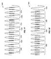
- FIG. 20shows how InsteonTM messages are transmitted, retransmitted, and acknowledged.
- FIG. 21is a block diagram showing how the InsteonTM Engine sends and receives messages.
- FIG. 22is a block diagram showing how the InsteonTM Engine transmits a message on the powerline.
- FIG. 23is a block diagram showing how the InsteonTM Engine receives a message from the powerline.
- FIG. 24is a flowchart showing how an InsteonTM RF daughter board communicates with an InsteonTM motherboard.
- FIG. 25is a flowchart showing how the InsteonTM RF daughter board transmits a message via RF.
- FIG. 26is a flowchart showing how the InsteonTM RF daughter board receives a message via RF.
- FIG. 27is a block diagram of an InsteonTM main board with optional daughter board.
- FIG. 28is a block diagram of an InsteonTM main board with an RF daughter board.
- FIG. 29is a block diagram of an InsteonTM main board with a USB daughter board.
- FIG. 30is a block diagram of an InsteonTM main board with an RS232 daughter board.
- FIG. 31is a block diagram of an InsteonTM main board with an Ethernet daughter board.
- FIG. 32shows a wire-in InsteonTM wall switch.
- FIG. 33shows a wire-in InsteonTM keypad controller.
- FIG. 34shows a plug-in InsteonTM lamp dimmer, appliance controller or communications interface device.
- FIG. 35shows a plug-in InsteonTM lamp dimmer with RF communications.
- FIG. 36shows a tabletop or wallmount InsteonTM pushbutton controller.
- FIG. 37shows an InsteonTM pushbutton controller with its hinged button cover opened.
- FIG. 38shows a tabletop or wallmount InsteonTM touchscreen controller.
- FIG. 39is a layout of specific InsteonTM messages that can be sent according to certain assumptions for an example of an InsteonTM usage session.
- FIG. 1shows a network of control and communication devices constructed according to the teachings of the present invention and hereinafter referred to as InsteonTM devices, INSTEONTM being a trademark of applicant's assignee.
- Electrical poweris most commonly distributed to buildings and homes in North America as two-phase 220-volt alternating current (220 VAC).
- the three-wire 220 VAC powerlineis split into two two-wire 110 VAC powerlines, known as Phase 1 and Phase 2 .
- Phase 1is designated 10
- Phase 2is designated 11 .
- Phase 1 wiringis typically used for half the circuits in the building, and Phase 2 is used for the other half.
- InsteonTM devicesapparatus according to the invention will be designated InsteonTM devices.
- InsteonTM devices 20 , 21 , 22 , and 23are shown connected to powerline phases 10 and 11 .
- InsteonTM devicescommunicate with each other over the powerline using the InsteonTM Powerline protocol 30 , which will be described in detail in what follows.
- X10 devices 51 and 52Also shown connected to the powerline are X10 devices 51 and 52 .
- X10 devicescommunicate over the powerline using the X10 protocol 50 .
- the InsteonTM Powerline protocol 30is compatible with the X10 protocol 50 , meaning that InsteonTM devices can both listen and talk to X10 devices using the X10 protocol 50 .
- X10 devicesare insensitive to the InsteonTM Powerline protocol 30 .
- InsteonTM devicesmay optionally comprise RF communication means, as is the case with InsteonTM devices 20 and 21 .
- InsteonTM RF devicescan communicate with other InsteonTM RF devices using the InsteonTM RF protocol 60 .
- InsteonTM devices that can use both the InsteonTM Powerline protocol 30 and the InsteonTM RF protocol 60solve a significant problem experienced by devices that only communicate via the powerline. Powerline signals on opposite powerline phases 10 and 11 are severely attenuated, because there is no direct circuit connection for them to travel over.
- a traditional solution to this problemis to connect a phase coupling device between the powerline phases, either by hardwiring it in at a junction box or by plugging it into a 220 VAC outlet.
- InsteonTM devicescapable of both InsteonTM Powerline 30 and InsteonTM RF 60 protocols automatically solves the powerline phase coupling problem whenever such devices are connected on opposite powerline phases.
- InsteonTM device 20can not only communicate via powerline with all devices on powerline phase 1 , 10 , but it can also communicate via powerline with all devices on powerline phase 2 , 11 , because it can communicate via InsteonTM RF protocol 60 with InsteonTM device 21 , which in turn is directly connected to powerline phase 2 , 11 .
- InsteonTM devicescan also interface with computers and other digital equipment.
- InsteonTM device 20can communicate with PC 71 using a serial link 70 .
- Serial communications 70is a means whereby networks of InsteonTM devices can bridge to networks of otherwise incompatible devices in a building, connect to computers, act as nodes on a local-area network (LAN), or get onto the global Internet. Coupled with the ability to download new software into InsteonTM devices, such connections allow networks of InsteonTM devices to perform very sophisticated new functions, including functions not envisioned at the time of manufacture or installation.
- FIG. 2shows how multiple InsteonTM devices, each of which is capable of repeating InsteonTM messages, form a reliable communications network.
- devices 110 and 111known as SignaLincTM devices, are capable of both InsteonTM powerline and InsteonTM RF communications.
- Devices 120 , 121 , 122 , and 123are only capable of InsteonTM RF communications.
- the remaining devices, 31 , 32 , 33 , 34 and 40 , 41 , 42 , 43are only capable of InsteonTM powerline communications.
- Every InsteonTM deviceis capable of repeating InsteonTM messages, using the InsteonTM protocol according to the present invention, as described hereinafter in detail. Adding more devices increases the number of available pathways for messages to travel. Path diversity results in a higher probability that a message will arrive at its intended destination, so the more InsteonTM devices in a network, the better.
- RF device 120desires to send a message to RF device 123 , but RF device 123 is out of range. The message will still get through, however, because devices within range of device 120 , say devices 110 and 121 , will receive the message and repeat it to other devices within range of themselves.
- device 110might reach devices 121 , 111 , and 122 , and devices 111 and 121 might be within range of the intended recipient, device 123 . Therefore, there are many ways for a message to travel: device 120 to 121 to 123 (2 hops), device 120 to 110 to 111 to 123 (3 hops), device 120 to 110 to 121 to 111 to 123 (4 hops) are some examples.
- FIG. 2also shows how path diversity on the powerline has a similar beneficial effect.
- powerline device 40may not be able to communicate directly with device 43 because of signal attenuation problems or because a direct path through the electric wiring does not exist. But a message from device 40 will still reach device 43 by taking a path via devices 40 to 111 to 43 (2 hops), or a path 40 to 41 to 111 to 43 (3 hops), or a path 40 to 41 to 42 to 43 (4 hops).
- FIG. 2shows how messages can travel among powerline devices that are installed on different phases of a building's wiring.
- At least one InsteonTM hybrid powerline/RF devicemust be installed on each powerline phase.
- SignaLincTM device 110is installed on phase A and SignaLincTM device 111 is installed on phase B.
- Direct RF paths between devices 110 to 111 (1 hop), or indirect paths using 110 , 121 and 111 or 110 , 122 and 111 (2 hops)allow messages to propagate between the powerline phases.
- All InsteonTM devicesare peers, meaning that any device can act as a master (sending messages), slave (receiving messages), or repeater (relaying messages). This relationship is illustrated in FIG. 3 , where InsteonTM device 210 , acting as a master, sends messages to multiple InsteonTM devices acting as slaves 220 , 221 , and 222 . Multiple InsteonTM devices acting as masters 230 , 231 , and 232 can also send messages to a single InsteonTM device acting as a slave 221 .
- Any InsteonTM devicecan repeat messages by acting as both a slave and a master, as with SwitchLincTM device 250 , which is shown relaying a message from ControLincTM device 240 acting as a master to LampLincTM device 260 acting as a slave.
- InsteonTM devicescommunicate with each other by sending messages. Messages sent over the powerline are broken up into packets, with each packet sent in conjunction with a zero-crossing of the voltage on the powerline. As shown in FIG. 4 , there are two kinds of InsteonTM messages, Standard Messages 310 and Extended Messages 320 . Standard Messages comprise five packets and Extended Messages comprise eleven packets. Each packet contains 24 bits of information, but the information is interpreted in two different ways. A Standard Packet 330 appears as the first packet in an InsteonTM message, as shown by the symbol 331 in Standard Message 310 and Extended Message 320 . The remaining packets in a message are Long Packets 340 , as shown by symbols 341 in Standard Message 310 and Extended Message 320 .
- Powerline packetsbegin with a series of Sync Bits. There are eight Sync Bits 332 in a Standard Packet 330 and there are two Sync Bits 342 in a Long Packet 340 . Following the Sync Bits are four Start Code Bits, shown as 333 in the Standard Packet 330 and as 343 in the Long Packet 340 . The remaining bits in a packet are Data Bits. There are twelve Data Bits 334 in a Standard Packet 330 , and there are eighteen Data Bits 344 in a Long Packet 340 .
- the total number of Data Bits in a Standard Message 310is 12+(4 ⁇ 18), which is 84, or 101 ⁇ 2 bytes. The last four data bits in a Standard Message are ignored, so the usable data is ten bytes.
- the total number of Data Bits in an Extended Message 320is 12+(10 ⁇ 18), which is 192, or 24 bytes.
- FIG. 5shows the contents of InsteonTM messages sent using RF. Because InsteonTM RF messaging is much faster than powerline messaging, there is no need to break up RF messages into smaller packets.
- An RF Standard messageis shown as 410 and an RF Extended message is shown as 420 . In both cases the message begins with two Sync Bytes 411 or 421 , followed by one Start Code Byte 412 or 422 .
- RF Standard messages 410contain ten Data Bytes (80 bits) 413
- RF Extended messages 420contain twenty-four Data Bytes (192 bits) 423 .
- the bytes in an InsteonTM messageare transmitted most-significant byte first, and the bits are transmitted most-significant bit first.
- the first field in an InsteonTM messageis the From Address 510 , a 24-bit (3-byte) number that uniquely identifies the InsteonTM device originating the message being sent. There are 16,777,216 possible InsteonTM devices identifiable by a 3-byte number. This number can be thought of as an ID Code or, equivalently, as an address for an InsteonTM device. During manufacture, a unique ID Code is stored in each device in nonvolatile memory.
- the second field in an InsteonTM messageis the To Address 520 , also a 24-bit (3-byte) number.
- Most InsteonTM messagesare of the Direct, or Point-to-Point (P2P), type, where the intended recipient is another single, unique InsteonTM device.
- P2PPoint-to-Point
- the third field, the Message Flags byte 530determines the type of InsteonTM Message. If the message is indeed Direct, the To Address 520 contains the 3-byte unique ID Code for the intended recipient.
- InsteonTM messagescan also be sent to all recipients within range, as Broadcast messages, or they can be sent to all members of a group of devices, as Group Broadcast messages.
- the To Address field 520contains a Device Type byte, a Device Subtype byte, and a Firmware Version byte.
- the To Address field 520contains a Group Number. Group Numbers can range from 0 to 255, given by one byte, so the two most-significant bytes of the three-byte field will be zero.
- the third field in an InsteonTM messagenot only signifies the Message Type but it also contains other information about the message.
- Message Typeswill be explained in more detail below.
- Bit 4the Extended flag 535 , is set to one if the message is an Extended message, i.e. contains 14 User Data bytes, or else it is set to zero if the message is a Standard message containing no User Data.
- the low nibblecontains two two-bit fields, Hops Left 536 (bits 3 and 2 ) and Max Hops 537 (bits 1 and 0 ). These two fields control message retransmission as explained below.
- the fourth field in an InsteonTM messageis a two-byte Command 540 , made up of Command 1 541 and Command 2 542 .
- the usage of this fielddepends on the Message Type as explained fully below.
- User Datacan be arbitrarily defined. If more than 14 bytes of User Data need to be transmitted, multiple InsteonTM Extended messages will have to be sent. Users can define a packetizing method for their data so that a receiving device can reliably reassemble long messages. Encrypting User Data can provide private, secure communications for sensitive applications such as security systems.
- the last field in an InsteonTM messageis a one-byte CRC, or Cyclic Redundancy Check 560 .
- the InsteonTM transmitting devicecomputes the CRC over all the bytes in a message beginning with the From Address 510 .
- Methods for computing a CRCare well known in the art. InsteonTM uses a software-implemented 7-bit linear-feedback shift register with taps at the two most-significant bits. The CRC covers 9 bytes for Standard messages and 23 bytes for Extended messages.
- An InsteonTM receiving devicecomputes its own CRC over the same message bytes as it receives them. If the message is corrupt, the receiver's CRC will not match the transmitted CRC. Detection of message integrity allows for highly reliable, verified communications.
- the InsteonTM ACK/NAK(acknowledge, non-acknowledge) closed-loop messaging protocol based on this detection method is disclosed below.
- FIG. 8enumerates the meaning of the bit fields in the Message Flags byte 530 of FIG. 6 and FIG. 7 .
- the Broadcast/NAK flag 611 (bit 7 ), the Group flag 612 (bit 6 ), and the ACK flag 613 (bit 5 )together denote the eight possible Message Types 610 .
- Broadcast messagescontain general information with no specific destination. They are directed to the community of devices within range. Broadcast messages are not acknowledged.
- Direct messagesalso referred to as Point-to-Point (P2P) messages
- P2PPoint-to-Point
- the recipientresponds to Direct messages by returning an Acknowledge message.
- the Broadcast/NAK flag 611will be set whenever the message is a Broadcast message or a Group Broadcast message. In those two cases the Acknowledge flag 613 will be clear. If the Acknowledge flag 613 is set, the message is an Acknowledge message. In that case the Broadcast/NAK flag 611 will be set when the Acknowledge message is a NAK, and it will be clear when the Acknowledge message is an ACK.
- the Group flag 612will be set to indicate the message is a Group Broadcast message or part of a Group-cleanup conversation. This flag will be clear for general Broadcast messages and Direct conversations.
- Broadcast messagesare Message Type 100.
- Direct (P2P) messagesare 000.
- An ACK of a Direct messageis 001, and a NAK of a Direct message is 101.
- a Group Broadcast messageis 110.
- Group Broadcastsare followed up by a series of Group-cleanup Direct messages 010 to each member of the group.
- Each recipient of a Group-cleanup Direct messagewill return an acknowledgement with a Group-cleanup ACK 011 or a Group-cleanup NAK 111 .
- Bit 4 , 621 in FIG. 8is the Extended Message flag 620 . As disclosed above, this flag is set for 24-byte Extended messages that contain a 14-byte User Data field, and the flag is clear for 10-byte Standard messages that do not contain User Data.
- Max Hops 640 and Hops Left 630manage message retransmission.
- All InsteonTM devicesare capable of repeating messages by receiving and retransmitting them. Without a mechanism for limiting the number of times a message can be retransmitted, an uncontrolled “data storm” of endlessly repeated messages could saturate the network.
- InsteonTM messagesare originated with the 2-bit Max Hops field 640 set to a value of 0,1, 2, or 3, and the 2-bit Hops Left field 630 set to the same value. A Max Hops value of zero tells other devices within range not to retransmit the message.
- a higher Max Hops valuetells devices receiving the message to retransmit it depending on the Hops Left field 630 . If the Hops Left value is one or more, the receiving device decrements the Hops Left value by one, then retransmits the message with the new Hops Left value. Devices that receive a message with a Hops Left value of zero will not retransmit that message. Also, a device that is the intended recipient of a message will not retransmit the message, no matter what the Hops Left value is.
- Max Hopsreally means maximum retransmissions allowed. All InsteonTM messages “hop” at least once, so the value in the Max Hops field 640 is one less than the number of times a message actually hops from one device to another. Since the maximum value in this field is three, there can be four actual hops, comprising the original transmission and three retransmissions. Four hops can span a chain of five devices. This situation is shown schematically in FIG. 9 .
- the flowchart in FIG. 10shows how an InsteonTM device receives messages and determines whether to retransmit them or process them.
- an InsteonTM devicereceives a message in step 710 , it determines in step 715 whether it needs to process the message or not.
- a devicewill need to process Direct messages if the device is the addressee, Group Broadcast messages if the device is a member of the group, and all Broadcast messages. If the message needs to be processed, the device does so in step 740 , and then if the message is found to be a Direct or Direct Group-cleanup message in step 745 , the device sends an Acknowledge message back to the message originator in step 750 and ends the task at step 755 .
- step 720determines if the message should be retransmitted.
- step 720the Max Hops bit field of the Message Flags byte is tested. If the Max Hops value is zero, processing is finished at step 755 , else the Hops Left bit field is tested at step 725 . If there are zero Hops Left, processing is finished at step 755 , else the device decrements the Hops Left value by one at step 730 and retransmits the message at step 735 .
- the flowchart in FIG. 11shows how an InsteonTM device sends messages to multiple recipient devices in a group.
- Group membershipis stored in a database in the device following a previous enrollment process.
- the devicefirst sends a Group Broadcast message intended for all members of a given group.
- the Message Type field in the Message Flags byteis set to 110 to signify a Group Broadcast message, and the To Address field is set to the group number, which can range from 0 to 255.
- the transmitting devicesends a Direct Group-cleanup message individually to each member of the group in its database.
- the devicefirst sets the message To Address to that of the first member of the group, then it sends a Direct Group-cleanup message to that addressee at step 820 . If Group-cleanup messages have been sent to every member of the group, as determined at step 825 , transmission is finished at step 835 . Otherwise, the device sets the message To Address to that of the next member of the group and sends the next Group-cleanup message to that addressee at step 820 .
- the flowchart in FIG. 12shows how Direct messages can be retried multiple times if an expected ACK is not received from the addressee.
- a devicesends a Direct or a Direct Group-cleanup message to an addressee at step 915 .
- the devicewaits for an Acknowledge message from the addressee. The exact timing for this step is given below. If at step 925 an Acknowledge message is received and it contains an ACK with the expected status, the process is finished at step 945 . If at step 925 an Acknowledge message is not received, or if it is not satisfactory, a Retry Counter is tested at step 930 . If the maximum number of retries has already been attempted, the process fails at step 945 .
- InsteonTM devicesdefault to a maximum number of retries of five. If fewer than five retries have been tried at step 930 the device increments its Retry Counter at step 935 . At step 940 the device will also increment the Max Hops field in the Message Flags byte, up to a maximum of three, in an attempt to achieve greater range for the message by retransmitting it more times by more devices. The message is sent again at step 915 .
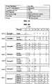
- FIG. 13summarizes all the fields in every type of InsteonTM message.
- Standard messages 1050are enumerated in lines 1051 through 1058 and Extended messages are enumerated in lines 1061 through 1068 .
- the figureclearly shows that the only difference between Standard and Extended messages is that the Extended Flag 1021 is clear for Standard messages and set for Extended messages, and Extended messages possess a 14-byte User Data field 1070 .
- the From Address 1010 , the To Address 1015 , the Message Flags 1020 , and the CRCs 1040 and 1045are as explained above.
- the Command 1 field 1030 and the Command 2 field 1035contain different information for each of the eight types of InsteonTM messages 1051 through 1058 or 1061 through 1068 .
- the two fields togethercontain a 2-byte command chosen from a possible 65,536 commands suitable for sending to all devices at once.
- a Broadcast commandcould direct ail devices to enter a system setup mode. Every receiving device contains a database of Broadcast commands that it is capable of executing.
- the two Command fields 1030 and 1035together comprise a 2-byte command chosen from a possible 65,536 commands suitable for sending to a single device.
- a Direct commandcould tell a LampLincTM lamp control device to turn on the lamp plugged into it. Every receiving device contains a database of Direct commands that it is capable of executing.
- the Insteon T protocolrequires that Direct messages be acknowledged.
- a receiving devicecan issue an acknowledgement of successful communication and completion of a task, i.e. an ACK as shown in line 1057 or 1067 . Otherwise the receiving device can issue a NAK as in line 1058 or 1068 , which indicates some kind of failure. If a receiving device fails to send an ACK or a NAK back to the originating device, the originating device can retry the message as shown in FIG. 12 .
- a receiving deviceswaps the From Address 1010 and the To Address 1015 in the message it received, and sets the Message Type bits to 001 for an ACK or 101 for a NAK.
- the receiving devicecomposes a 2-byte status response code for an ACK or else a 2-byte reason code for a NAK, which it inserts in the Command fields 1030 and 1035 .
- These response codesare created according to a set of rules encoded in the software of the device.
- a lamp dimmerreceives a command to set the lamp to a certain brightness level, issued as a Set Brightness code in the Command 1 field 1030 and the desired brightness level as one of 256 values in the Command 2 field 1035 , the dimmer could respond with an ACK message containing the same two bytes in the Command fields 1030 and 1035 to indicate successful execution of the command.
- InsteonTM message typesare for dealing with groups of devices.
- Group Broadcast messagesexist as a performance enhancement. While it is true that all the members of a group of devices could be sent individual Direct messages with the same command (to turn on, for example), it would take a noticeable amount of time for all the messages to be transmitted in sequence. The members of the group would not execute the command all at once, but rather in the order received. InsteonTM solves this problem by first sending a Group Broadcast message, then following it up with individual Direct “Group-cleanup” messages.
- Group Broadcast messagesshown in lines 1052 and 1062 of FIG. 13 , contain a Group Number in the To Address field 1015 , and a Group Command in the Command fields 1030 and 1035 .
- the Group Commandwill be sent in the Command 1 field 1030 and the Group Number will be sent in the Command 2 field 1035 .
- Recipients of a Group Broadcast messagecheck the Group Number in the To Address field 1015 against their own group memberships recorded in a database.
- This databasepreferably in nonvolatile memory, is established during a prior group enrollment process. If the recipient is a member of the group being broadcast to, it executes the command in the Command 1 field 1030 . Since the Group Command only occupies one byte, the other byte in field 1035 can be a parameter or a subcommand.
- Group Broadcast command recipientscan then expect a Direct individually-addressed Group-cleanup message. If the recipient has already executed the Group Command in field 1030 , it will not execute the command a second time. However, if the recipient missed the Group Broadcast command for any reason, it will not have executed it, so it will execute the command after receiving the Direct Group-cleanup message.
- the recipient deviceAfter receiving the Direct Group-cleanup message and executing the Group Command, the recipient device will respond with a Group-cleanup ACK message, or if something went wrong, a Group-cleanup NAK message.
- the Command 1 field 1030will contain the same one-byte Group Command received during the Direct Group-cleanup message.
- the other byte in the Command 2 field 1035will contain a one-byte ACK Status code in the case of an ACK, or a one-byte NAK Reason code in the case of a NAK.
- These one-byte codescan be a subset of the corresponding two-byte codes used in Direct ACK and Direct NAK messages.
- InsteonTM devicescommunicate on the powerline by adding a signal to the powerline voltage.
- powerline voltageis 110 VAC RMS, alternating at 60 Hz.
- An InsteonTM powerline signaluses a carrier frequency of 131.65 KHz, with a nominal amplitude of 4.64 volts peak-to-peak into a 5 ohm load.
- the impedance of powerlinesvaries widely, depending on the powerline configuration and what is plugged into it, so measured InsteonTM powerline signals can vary from sub-millivolt to more than 5 volts.
- InsteonTM datais modulated onto the 131.65 KHz carrier using binary phase-shift keying, or BPSK, chosen for reliable performance in the presence of noise.
- BPSKbinary phase-shift keying
- FIG.14shows an InsteonTM 131.65 KHz powerline carrier signal with alternating BPSK bit modulation.
- InsteonTMuses ten cycles of carrier for each bit.
- Bit 1 1110interpreted as a one, begins with a positive-going carrier cycle.
- Bit 2 1120interpreted as a zero, begins with a negative-going carrier cycle.
- Bit 3 1130begins with a positive-going carrier cycle, so it is interpreted as a one. Note that the sense of the bit interpretations is arbitrary. That is, ones and zeros could be reversed as long as the interpretation is consistent. Phase transitions only occur when a bitstream changes from a zero to a one or from a one to a zero. A one followed by another one, or a zero followed by another zero, will not cause a phase transition. This type of coding is known as NRZ, or non-return to zero.
- FIG. 14shows abrupt phase transitions of 180 degrees at the bit boundaries 1115 and 1125 .
- Abrupt phase transitionsintroduce troublesome high-frequency components into the signal's spectrum.
- Phase-locked detectorscan have trouble tracking such a signal.
- InsteonTMuses a gradual phase change to reduce the unwanted frequency components.
- FIG. 15shows the same BPSK signal with gradual phase shifting.
- the transmitterintroduces the phase change by inserting 1.5 cycles of carrier at 1.5 times the 131.65 KHz frequency.
- the phase of the carrieris reversed at the end of the period due to the odd number of half-cycles. Note the smooth transitions 1115 and 1125 in the figure.
- All InsteonTM powerline packetscontain 24 bits, as was shown in FIG. 4 . Since a bit takes ten cycles of 131.65 KHz carrier, there are 240 cycles of carrier in an InsteonTM packet, meaning that a packet lasts 1.823 milliseconds.
- the powerline environmentis notorious for uncontrolled noise, especially high-amplitude spikes caused by motors, dimmers and compact fluorescent lighting. This noise is minimal during the time that the current on the powerline reverses direction, a time known as the powerline zero crossing. Therefore, InsteonTM packets are transmitted near the zero crossing, as shown in FIG. 16 .
- FIG. 16shows a single powerline cycle 1205 , which possesses two zero crossings 1210 and 1215 .
- An InsteonTM packet 1220is shown at zero crossing 1210 and a second InsteonTM packet 1225 at zero crossing 1215 .
- InsteonTM packetsbegin 800 microseconds before a zero crossing and last until 1023 microseconds after the zero crossing.
- An expanded view 1240 of an InsteonTM packet 1250is shown with an X10 burst 1260 superimposed.
- the X10 signal 1260begins at the zero crossing 1270 , 800 microseconds after the beginning of the InsteonTM packet 1250 . Both signals end at approximately the same time, 1023 microseconds after the zero crossing.
- InsteonTM devicesachieve compatibility with X10 by listening for an InsteonTM signal beginning 800 microseconds before the zero crossing.
- InsteonTM receivers implemented in softwarecan be very sensitive, but at the cost of having to receive a substantial portion of a packet before being able to validate that a true InsteonTM packet is being received.
- Reliable validationmay not occur until as much as 450 microseconds after the zero crossing, although an InsteonTM device will still begin listening for a possible X10 burst right at the zero crossing. If at the 450-microsecond mark the InsteonTM receiver validates that it is not receiving an InsteonTM packet but that there is an X10 burst present, the InsteonTM receiver will switch to X10 mode and listen for a complete X10 message over the next 11 powerline cycles. If the InsteonTM device detects that it is receiving an InsteonTM packet, it will remain in InsteonTM mode and listen for X10 until it recelves the rest of the complete InsteonTM message.
- InsteonTM devicesimplemented using substantially more signal detection hardware, as can be achieved in an application-specific integrated circuit (ASIC) with second-order phase-locked loops, can detect the presence of valid InsteonTM packets during the 800 microseconds before the zero crossing. Able to independently and simultaneously listen for X10, such devices can boost X10 bursts after only a short hardware X10 detector delay.
- ASICapplication-specific integrated circuit
- FIG. 16also shows that the raw bitrate for InsteonTM is much faster for InsteonTM than for X10.
- An InsteonTM bit 1280requires ten cycles of 131.65 KHz carrier, or 75.96 microseconds, whereas an X10 bit requires two 120-cycle bursts 1285 of 120 KHz.
- One X10 burst 1285takes 1000 microseconds, but since each X10 burst is sent at a zero crossing, it takes 16,667 microseconds to send the two bursts in a bit, resulting in a sustained bitrate of 60 bits per second.
- InsteonTM packetscomprise 24 bits, and an InsteonTM packet can be sent during each zero crossing, so the nominal sustained bitrate for InsteonTM is 2880 bits per second, 48 times faster than X10.
- InsteonTMwaits for one or two additional zero crossings after sending a message to allow time for potential retransmission of the message by InsteonTM RF devices.
- FIG.17shows a series of five-packet Standard InsteonTM messages 1310 being sent on the powerline signal 1305 .
- InsteonTMwaits for one zero crossing 1320 after each Standard packet before sending another packet.
- FIG. 18shows a series of eleven-packet Extended InsteonTM messages 1330 being sent on the powerline signal 1305 .
- InsteonTMwaits for two zero crossings 1340 after efter Extended packet before sending another packet.
- InsteonTM Standard messagescontain 120 raw data bits and require six zero crossings, or 50 milliseconds to send.
- Extended messagescontain 264 raw data bits and require thirteen zero crossings, or 108.33 milliseconds to send. Therefore, the actual raw bitrate for InsteonTM is 2400 bits per second for Standard messages, or 2437 bits per second for Extended messages, instead of the 2880 bits per second it would be without waiting for the extra zero crossings.
- InsteonTM Standard messagescontain 9 bytes (72 bits) of usable data, not counting packet sync and start code bytes, nor the message CRC byte.
- Extended messagescontain 23 bytes (184 bits) of usable data using the same criteria. Therefore, the bitrates for usable data are further reduced to 1440 bits per second for Standard messages and 1698 bits per second for Extended messages. If one only counts the 14 bytes (112 bits) of User Data in Extended messages, the User Data bitrate is 1034 bits per second.
- RF InsteonTM devicescan send and receive the same messages that appear on the powerline. Unlike powerline messages, however, messages sent by RF are not broken up into smaller packets sent at powerline zero crossings, but instead are sent whole, as was shown in FIG. 5 . As with powerline, there are two RF message lengths: Standard 10-byte messages and Extended 24-byte messages.
- FIG. 19gives the specifications for InsteonTM RF signaling.
- the center frequencylies in the band 902 to 924 MHz, which is permitted for unlicensed operation in the United States.
- Each bitis Manchester encoded, meaning that two symbols are sent for each bit.
- a one-symbol followed by a zero-symboldesignates a one-bit
- a zero-symbol followed by a one-symboldesignates a zero-bit.
- Symbolsare modulated onto the carrier using frequency-shift keying (FSK), where a zero-symbol modulates the carrier half the FSK deviation frequency downward and a one-symbol modulates the carrier half the FSK deviation frequency upward.
- the FSK deviation frequency chosen for InsteonTMis 64 KHz.
- Symbolsare modulated onto the carrier at 38,400 symbols per second, resulting in a raw data rata of half that, or 19,200 bits per second.
- the typical range for free-space receptionis 150 feet, which is reduced in the presence of walls and other RF energy absorbers.
- InsteonTM devicestransmit data with the most-significant bit sent first.
- RF messagesbegin with two sync bytes 411 or 421 comprising AAAA in hexadecimal, followed by a start code byte 412 or 422 of C3 in hexadecimal.
- Ten data bytes 413follow in Standard messages, or twenty-four data bytes 423 in Extended messages.
- the last data byte in a messageis a CRC over the data bytes as disclosed above.
- the InsteonTM Messaging protocolincludes message retransmission, a method for enabling other InsteonTM devices to help relay a message to increase its range.
- messagecan be retransmitted a maximum of three times. The larger the number of retransmissions, however, the longer the message will take to complete.
- An InsteonTM Message on the powerlineoccupies either six or thirteen zero crossing periods, depending on whether the message is Standard or Extended. This message transmission time, six or thirteen powerline half-cycles, is called a timeslot in the following discussion.
- InsteonTM Messagecan be transmitted, retransmitted, or acknowledged.
- the entire process of communicating an InsteonTM Message, which may involve retransmissions and acknowledgements,will occur over integer multiples of timeslots.
- Example 1 1401shows a Broadcast message with no retransmissions.
- the Tindicates that the Sender has originated and transmitted a single message. There is no acknowledgement that intended recipients have heard the message.
- the messagerequires one timeslot of six or thirteen powerline zero crossings to complete.
- Example 2shows a Broadcast message with a Max Hops of one. Max Hops can range from zero to three as explained above in conjunction with FIG. 9 .
- the Sendertransmits a Broadcast message as signified by the T.
- Another InsteonTM devicefunctioning as a repeater, listens to the message, as signified by an L, and then retransmits it in the next timeslot as indicated by the R.
- Example 3 1403shows the progression of the message among an originating Sender and three repeating devices.
- Example 3assumes that the range between repeaters is such that only adjacent repeaters can hear each other. Also, only Repeater 1 can hear the Sender. Note that the Sender will not retransmit its own message.
- Example 4shows what happens if the Max Hops value is zero.
- the Adesignates the timeslot in which the Recipient acknowledges receipt of the Direct message.
- the Cshows the timeslot when the Sender finds that the message is confirmed.
- Example 7, 1407shows what happens when Max Hops is three and three retransmissions are in fact needed for the message to reach the Recipient. Note that if the Sender or Recipient were to hear the other's message earlier than shown, it still must wait until Max Hops timeslots have occurred after the message was originated before it is free to send its own message. If devices did not wait, they would jam each other by sending different messages in the same timeslot. A device can calculate how many timeslots have passed prior to receiving a message by subtracting the Hops Left number in the received message from the Max Hops number.
- InsteonTM devicescan determine when all of the possible retransmissions and acknowledgements for an InsteonTM message will be completed according to the above protocol. Similarly, InsteonTM devices can monitor X10 message traffic and thereby calculate when an X10 command will finish being sent. By waiting until preexisting message traffic is finished before transmitting, InsteonTM devices that wish to originate a message can avoid possible jamming of any InsteonTM or X10 communications already in progress. This form of listen-before-talk is called “politeness.”
- Politenessis further extended if an InsteonTM device wishes to send more than one message in a row. In that case, the device waits one additional powerline zero crossing period before initiating a follow-on message. The additional time gives other InsteonTM devices that may have been waiting for message traffic to complete an opportunity to transmit, and prevents a single device from monopolizing the channel with a long series of its own messages.
- InsteonTM systemsachieve a marked increase in the reliability of communications. The reason is that multiple InsteonTM devices can transmit the same message at the same time within a given timeslot. InsteonTM devices within range of each other thus “help each other out.” Most networking protocols for shared physical media prohibit multiple devices from simultaneously transmitting within the same band, as discussed above in the section on prior art. In contrast, InsteonTM turns what is usually a problem into a benefit by insuring that devices transmitting simultaneously will be sending the same messages in synchrony with each other.
- InsteonTM receivershave a wide dynamic range, from millivolts to five volts or so, which will allow them to track signals even if they fade temporarily. Adding more transmitters reduces the probability of signal cancellation even more. Rather, the probability that the sum of all the signals will increase in signal strength becomes much greater.
- the InsteonTM powerline carrieris modulated using binary phase-shift keying (BPSK), meaning that receivers are looking for 180-degree phase shifts in the carrier to detect changes in a string of bits from a one to a zero or vice-versa.
- BPSKbinary phase-shift keying
- Multiple transmittersregardless of the absolute phase of their carriers, will produce signals whose sum still possesses 180-degree phase reversals at bit-change boundaries, so long as their relative carrier frequencies to do not shift more than a few degrees over a packet time.
- bit timings for each transmitterneed to be fairly well locked, so InsteonTM transmitters are synchronized to powerline zero crossings.
- An InsteonTM bitlasts for ten cycles of the 131.65 KHz powerline carrier, or 76 microseconds.
- the powerline zero crossing detectorshould be accurate within one or two carrier periods so that bits received from multiple transmitters will overlay each other.
- InsteonTM powerline transmitters simulcasting the same messagewill improve the strength of the powerline signal throughout a building. Since RF signaling is used as an extension to powerline signaling, it also is based on simulcasting. However, with RF, even when the carrier and data are ideally synchronized, interference patterns will form where the carrier signal is canceled. As with powerline, for a cancellation to occur, two carriers must be 180 degrees out of phase and the amplitudes must be the same. Perfect cancellation is practically impossible to obtain. In general, two co-located carriers on the same frequency with random phase relationships and the same antenna polarization will sum to a power level greater than that of just one transmitter only 67% of the time. As one of the transmitters is moved away from a receiver, the probability of cancellation drops further. As the number of transmitters increases, the probability of cancellation becomes nearly zero.
- Mobile InsteonTM RF devicessuch as handheld controllers, are battery operated. To conserve power, mobile devices are not configured as RF repeaters, but only as message originators, so simulcasting is not an issue. InsteonTM devices that do repeat RF messages are attached to the powerline, so most of them will not be moved around after initial setup. During setup, RF devices can be located, and their antennas adjusted, so that no signal cancellation occurs. With the location of the transmitters fixed, the non-canceling configuration will be maintained indefinitely.
- InsteonTM RF devices attached to the powerlineuse the zero crossing for message synchronization. These devices receive InsteonTM messages synchronously on the powerline, synchronously via RF from RF repeaters, or possibly asynchronously via RF from mobile RF devices. Messages that need to be retransmitted will have a Hops Left count greater than zero. If the InsteonTM device receives such a message from the powerline, it will retransmit the message using RF as soon as it has received the last packet of the powerline message, then it will retransmit the message on the powerline in the next timeslot. If the device receives the message via RF, it will retransmit the message on the powerline in the next timeslot, then it will retransmit the message using RF immediately after sending the last packet of the powerline message.
- the InsteonTM Enginecomprises hardware and firmware that enable InsteonTM devices to send and receive InsteonTM messages.
- FIG. 21shows the overall flow of information through the InsteonTM Engine.
- Received signals 1510come from the powerline or via RF.
- Signal conditioning circuitry 1515processes the raw signal and converts it into a digital bitstream.
- Message receiver firmware 1520processes the bitstream as required and places the message payload data into a buffer 1525 which is available to the application running on the InsteonTM device.
- the message controller 1550tells the application that data is available using control flags 1555 .
- the applicationplaces message data in a buffer 1545 , then tells the message controller 1550 to send the message using control flags 1555 .
- the message transmitter firmware 1540processes the message into a raw bitstream, which it feeds to the transmitter section of the modem 1535 .
- the modem transmittersends the bitstream as a powerline or RF signal 1530 .
- the message transmitter 1540 of FIG. 21is given in greater detail in FIG. 22 , which shows how the InsteonTM Engine sends an InsteonTM Message on the powerline.
- An InsteonTM applicationfirst composes a message 1610 that it wishes to send, excluding the CRC byte, and puts the message data in the transmit buffer 1615 .
- the applicationthen tells the transmit controller 1625 to send the message by setting appropriate control flags 1620 .
- the transmit controller 1625packetizes the message data by using multiplexer 1635 to put sync bits and a start code from generator 1630 at the beginning of a packet followed by data shifted out of the first-in first-out (FIFO) transmit buffer 1615 .
- FIFOfirst-in first-out
- a CRC generator 1630calculates the CRC byte, which is appended to the bitstream by multiplexer 1635 as the last byte in the last packet of the message.
- the bitstreamis buffered in a shift register 1640 and clocked out in phase with the powerline zero crossings detected by zero crossing detector 1645 .
- the BPSK modulator 1655shifts the phase of the 131.65 KHz carrier from carrier generator 1650 by 180 degrees for zero-bits, and leaves the carrier unmodulated for one-bits. Note that the phase is shifted gradually over one carrier period as disclosed in conjunction with FIG. 15 .
- the modulated carrier signalis applied to the powerline by the modem transmit circuitry 1535 of FIG. 21 .
- the message receiver 1520 of FIG. 21is given in greater detail in FIG. 23 , which shows how the InsteonTM Engine receives InsteonTM messages from the powerline.
- the modem receive circuitry 1515 of FIG. 21conditions the signal on the powerline and transforms it into a digital data stream that the firmware in FIG. 23 processes to retrieve InsteonTM messages.
- Raw data 1710 from the powerlineis typically very noisy, because the received InsteonTM signal can have an amplitude as low as a only few millivolts, and the powerline often carries high-energy noise spikes or other noise of its own. Therefore, in a preferred embodiment, a Costas phase-locked loop (PLL) 1720 , implemented in firmware, is used to find the BPSK InsteonTM signal within the noise.
- PLLCostas phase-locked loop
- the phase-lock detector 1725provides one input to the window timer 1745 , which also receives a zero crossing signal 1750 and an indication that a start code in a packet has been found by start code detector 1740 .
- the Costas PLL 1720sends data to the bit sync detector 1730 .
- the bit sync detector 1730will be able to recover a bit clock, which it uses to shift data into data shift register 1735 .
- the start code detector 1740looks for the start code following the sync bits and outputs a detect signal to the window timer 1745 after it has found one.
- the window timer 1745determines that a valid InsteonTM packet is being received when the data stream begins 800 microseconds before the powerline zero crossing, the phase lock detector 1725 indicates lock, and detector 1740 has found a valid start code.
- the window timer 1745sets a start detect flag 1790 and enables the receive buffer controller 1755 to begin accumulating packet data from shift register 1735 into the FIFO receive buffer 1760 .
- the storage controller 1755insures that the FIFO 1760 only builds up the data bytes in a message, and not sync bits or start codes. It stores the correct number of bytes, 10 for a Standard message and 24 for an Extended message, by inspecting the Extended Message bit in the Message Flags byte. When the correct number of bytes has been accumulated, a HaveMsg flag 1765 is set to indicate a message has been received.
- Costas PLLshave a phase ambiguity of 180 degrees, since they can lock to a signal equally well in phase or antiphase. Therefore, the detected data from PLL 1720 may be inverted from its true sense.
- the start code detector 1740resolves the ambiguity by looking for the true start code, C3 hexadecimal, and also its complement, 3C hexadecimal. If it finds the complement, the PLL is locked in antiphase and the data bits are inverted.
- a signal from the start code detector 1740tells the data complementer 1770 whether to un-invert the data or not.
- the CRC checker 1775computes a CRC on the received data and compares it to the CRC in the received message. If they match, the CRC OK flag 1780 is set.
- Data from the complementer 1770flows into an application buffer, not shown, via path 1785 .
- the applicationwill have received a valid message when the HaveMsg flag 1765 and the CRC OK flag 1780 are both set.
- FIG. 24shows how the InsteonTM Engine sends and receives messages via RF.
- an InsteonTM device for the powerlinecan be fitted with a daughter board that extends the device's capabilities.
- the daughter board 1850 shown in FIG. 24provides an RF interface to the host 1810 . It has an onboard RF transceiver and its own microcontroller unit (MCU), which acts as a slave to the host MCU.
- MCUmicrocontroller unit
- the host and the slave MCUscommunicate using the well-known RS232 serial protocol 1880 at TTL logic levels.
- the InsteonTM Engine running on the host MCUexecutes the procedure beginning at step 1812 . First, it sends a transmit command to the slave MCU on the RF daughter board at step 1814 , then it waits for an acknowledgement that the command has been received and the slave MCU is ready to transmit at step 1816 . When the slave MCU is ready, the host sends the data in the InsteonTM Message to it in step 1818 . Since the slave MCU handles all the details of sending an RF message, the host can resume other operations at step 1820 .
- the hostexecutes the procedure beginning at step 1822 .
- the hostchecks its RS232 receive buffer at step 1824 to see if the slave has notified it that an RF message is available. If not, the host continues with other processing at step 1830 , but if there is an RF message the host sends an acknowledgement to the slave at step 1826 .
- the slavesends the data in the message to the host in step 1828 and the host continues processing in step 1830 .
- the slave MCU on the RF daughter board 1850handles its tasks as shown in the flowchart on the right side of FIG. 24 .
- the slave MCUperiodically checks its RS232 receive buffer at step 1852 for commands from the host.
- step 1854if the slave finds that it has received a command from the host to transmit an RF message, it acknowledges the command at step 1856 , receives the message data from the host at step 1858 , and then composes the RF message and transmits it at step 1859 .
- the slave MCUfinds it has not received a transmit command from the host, it attempts to receive RF data from the onboard RF transceiver at step 1860 . If the slave has not received a valid RF message at step 1862 it reenters its polling loop at step 1852 and tries again. If, however, the slave MCU has received a valid RF message, it notifies the host at step 1864 and waits for an acknowledgement that the host is ready to receive the data at step 1866 . When the host sends an acknowledgement, the slave sends the data in the message to the host in step 1868 , then resumes its polling loop at step 1852 .
- FIG. 25shows in greater detail how the slave MCU 1925 composes and transmits an RF message at step 1859 of FIG. 24 .
- the stepsare similar to those for sending powerline messages given in FIG. 22 , except that RF messages are sent all at once in a single packet.
- the host MCUcomposes a message that it wishes to send, excluding the CRC byte, and sends the message data to the slave MCU 1925 via RS232 serial communications 1920 .
- the slaveputs the message data into transmit buffer 1915 .
- the slave MCU 1925uses multiplexer 1935 to put sync bits and a start code from generator 1930 at the beginning of the RF message followed by data shifted out of the first-in first-out (FIFO) transmit buffer 1915 .
- FIFOfirst-in first-out
- a CRC generator 1930calculates the CRC byte, which is appended to the bitstream by multiplexer 1935 as the last byte of the message.
- the bitstreamis buffered in a shift register 1940 and clocked out to the RF transceiver 1955 .
- the transceivergenerates an RF carrier, translates the bits in the message into Manchester-encoded symbols, FM modulates the carrier with the symbol stream, and transmits the resulting RF signal using antenna 1960 .
- the RF transceiver 1955is a single-chip hardware device and the other blocks in the figure are implemented in firmware running on the slave MCU 1925 .
- FIG. 26shows in greater detail how the slave MCU receives an RF message at step 1860 of FIG. 24 .
- the stepsare similar to those for receiving powerline messages given in FIG. 23 , except that RF messages are sent all at once in a single packet.
- the RF transceiver 2015receives an RF transmission from antenna 2010 and FM demodulates it to recover the baseband Manchester symbols.
- the sync bits at the beginning of the messageallow the transceiver to recover a bit clock, which it uses to recover the data bits from the Manchester symbols.
- the transceiveroutputs the bit clock and the recovered data bits to shift register 2020 , which accumulates the bitstream in the message.
- the start code detector 2025looks for the start code following the sync bits at the beginning of the message and outputs a detect signal 2060 to the slave MCU 2065 after it has found one.
- the start detect flag 2060enables the receive buffer controller 2030 to begin accumulating message data from shift register 2020 into the FIFO receive buffer 2035 .
- the storage controller 2030insures that the FIFO 2035 only stores the data bytes in a message, and not the sync bits or start code. It stores the correct number of bytes, 10 for a Standard message and 24 for an Extended message, by inspecting the Extended Message bit in the Message Flags byte. When the correct number of bytes has been accumulated, a HaveMsg flag 2055 is set to indicate a message has been received.
- the CRC checker 2040computes a CRC on the received data and compares it to the CRC in the received message. If they match, the CRC OK flag 2045 is set. When the HaveMsg flag 2055 and the CRC OK flag 2045 are both set, the message data is ready to be sent to the host via RS232 communications 2070 .
- the RF transceiver 2015is a single-chip hardware device and the other blocks in the figure are implemented in firmware running on the slave MCU 2065 .
- the powerline interface 2150comprises a powerline transmitter 2152 and receiver 2154 , which are capable of sending and receiving both InsteonTM and X10 signals over the powerline.
- the load control 2156typically comprises a triac or a relay.
- a triaccan provide variable power to resistive loads, such as lamps, in order to dim them. Inductive or high-power loads can be switched on or off using a mechanical relay.
- Some load control modulesare also capable of sensing whether a controlled load has been turned on or off manually. For example, if a lamp is plugged into an InsteonTM lamp controller and a person turns on the lamp using the switch on the lamp, the load control module can sense the current draw and turn on the triac so the lamp will illuminate. Conversely, if the triac turns on but the lamp's switch is off, the load control module can sense the problem so that the InsteonTM device can display or send an appropriate error message.
- InsteonTM devicescan incorporate a display, such as a monochrome or color LCD as used in cellphones, PDAs or PCs. There may be multiple pushbuttons configured as a keypad or keyboard, or there may be other types of sensing devices such as proximity detectors.
- a displaysuch as a monochrome or color LCD as used in cellphones, PDAs or PCs.
- pushbuttonsconfigured as a keypad or keyboard, or there may be other types of sensing devices such as proximity detectors.
- proximity detectorsOne skilled in the art can envision a broad array of devices into which InsteonTM technology can be embedded, and the preferred embodiment disclosed here is only one configuration of many possible alternative configurations.
- FIG. 28shows an InsteonTM main board 2210 with an MCU 2215 connected via RS232 2230 to an RF daughter board 2220 .
- the RF daughter boardcomprises its own MCU 2222 in communication with an RF transceiver chip 2224 .
- the RF transceivercomprises circuitry 2226 to both send and receive RF signals using antenna 2228 .
- FIG. 29shows an InsteonTM main board 2310 with an MCU 2315 connected to a Universal Serial Bus (USB) daughter board 2320 .
- the USB boardcomprises its own slave MCU 2322 with an on-chip USB interface, a realtime clock (RTC) 2324 , and additional non-volatile random-access memory (NVRAM) 2326 .
- the slave MCU 2322communicates with the host MCU 2315 using serial RS232 2330 .
- the RTC and the NVRAMare connected to the host MCU via an I2C bus 2335 .
- the USB interface 2328enables InsteonTM devices to interface with any other equipment that has a USB port.
- FIG. 30shows an InsteonTM main board 2410 with an MCU 2415 connected to an RS232 daughter board 2420 .
- the RS232 boardcomprises an RS232 Transceiver 2422 with a level converter 2423 , a realtime clock (RTC) 2424 , and additional non-volatile random-access memory (NVRAM) 2426 .
- the RTC and the NVRAMare connected to the host MCU via an I2C bus 2435 .
- the host MCU 2415connects via the RS232 serial link 2430 to the RS232 interface 2428 , thus enabling InsteonTM devices to interface with any other equipment that has an RS232 port.
- FIG. 31shows an InsteonTM main board 2510 with an MCU 2515 connected to an Internet protocol (IP) daughter board 2520 , which allows InsteonTM devices to communicate with a local-area network (LAN) or the Internet.
- IPInternet protocol
- the IP board 2520has its own slave MCU 2522 running a Dynamic Host Configuration Protocol (DHCP) client, an Address Resolution Protocol (ARP) client, and a Hypertext Transport Protocol (HTTP) stack.
- DHCPDynamic Host Configuration Protocol
- ARPAddress Resolution Protocol
- HTTPHypertext Transport Protocol
- the MCU 2522attaches to an Ethernet LAN 2540 via Ethernet controller 2528 and physical interface 2529 .
- the LANcan connect to the Internet 2544 via a router 2542 . Once on the Internet, the InsteonTM device can interface with computers 2546 anywhere in the world.
- Products that can be improved using InsteonTM technologyinclude (1) electrical devices such as plug-in or wire-in dimmers, switches, or outlets, (2) home appliances; (3) annunciators, thermostats, access controllers; (4) pool/spa and irrigation controllers; (5) environmental, device status, motion, room occupancy, or contact sensors; and (6) PC, touchscreen, keypad, handheld, or keyfob controllers.
- InsteonTM devicescan interoperate with other devices communicating using WiFi (IEEE 802.11), BlueTooth, ZigBee, ZWave, HomePlug, HomeRF, Intellon, Echelon, CEBus, or other future technology.
- WiFiIEEE 802.11
- ZigBeeZigBee
- ZWaveZeroWave
- HomePlugHomePlug
- HomeRFIntellon
- EchelonEchelon
- CEBusor other future technology.
- a network of InsteonTM devices with at least one device having USB, RS232, or Ethernet communications capabilitiescan connect to a PC or access points to the Internet. New software can be downloaded to InsteonTM devices, making them capable of being upgraded with new capabilities in the future. This same connectivity also allows local networks of InsteonTM devices to interact with remote processes.
- An infrastructure of low-cost, reliable devices capable of being upgraded and interfaced remotelycan be used in so many different ways that it is not possible to foresee them all.
- FIG. 33shows an InsteonTM device 2710 that wires into a junction box in place of a wall switch. It has eight pushbuttons 2720 , which are illuminated from behind by white LEDs that can be filtered to be any color. Transparent legends, printable by a laser printer, can be placed behind the buttons to label them.
- the item 2750serves the same purpose as item 2650 in FIG. 32 .
- FIG. 37shows another version of a pushbutton controller 3110 with substantially more buttons 3120 .
- Cover 3130when closed, covers all but eight of the buttons, providing a simpler, less cluttered interface to the user, similar to that of FIG. 36 .
- FIG. 38shows an InsteonTM controller device 3210 with a touchscreen liquid-crystal display (LCD) 3230 and six pushbuttons 3220 .
- the touchscreen LCDcan be monochrome or color and optionally backlit.
- LED 3240provides additional user feedback.
- InsteonTM Extended messagesprogrammers are free to devise all kinds of meanings for the User Data that can be exchanged among devices.
- device firmwarecould include an interpreter for an entire high-level language that is compiled into token strings and downloaded into devices using Extended messages.
- firmwareFor the switch to control the lamp modules, there must be firmware in the devices that enables them to be linked as members of a common group. This firmware might respond to a series of InsteonTM Messages sent by a PC via a USB or RS232 interface device, or it might enable a user to link the devices manually by pressing buttons.
- One possible firmware design that would allow users to manually accomplish the above group enrollmentmight be the following.
- the switch modulewould broadcast a message giving its device type and a “Set Button Pressed” command.
- the userwould push the Setup button 2850 of lamp module A of FIG. 34 .
- Lamp Module Abroadcasts its device address, device type, and a “Set Button Pressed” command.
- the usercan operate both lamp modules at once using the switch module.
- the lampscould be turned on, and by pressing the bottom of the paddle, the lamps could be turned off. Pressing and holding the top of the paddle could brighten the lamps gradually until the user lets up. Dimming the lamps could be similarly accomplished using the bottom of the paddle.
- Line 3310is a Group Broadcast message telling group 1 to turn on.
- the From Address, 00003Eis the address of the switch module.
- the To Address, 000001is the group number.
- Command 1the Group Command 01 , means “Turn On,” and Command 2 , the parameter, is 00.
- the two lamp modulesreceive this message, check their group database, and finding that they are indeed members of group 1, execute the command to turn on their loads. Other recipients of the message are not members of group 1, so they ignore the message.
- the switch modulefollows up the Group Broadcast command with a Direct Group-cleanup message to lamp module A, repeating the “Turn On” command. Again the From Address is 00003E, but this time the To Address is 000054, or lamp module A.
- the flags, 00signify Direct, Standard message, 0 Hops left, 0 Max Hops.
- Command 1, 41means “Group-cleanup, Turn On,” and Command 2, the group number, is 01.
- Line 3330is the acknowledgement from lamp module A.
- the From Address, 000054is lamp module A, and the To Address, 00003E, is the switch module.
- Command 1 and Command 2are repeats of the same fields in the Direct message, 41 and 01.
- Line 3340 and line 3350are the Direct message and the ACK for lamp module B.
- the fieldsare the same except that the address of lamp module B, 000051, is substituted for 000054, the address of lamp module A.
Landscapes
- Engineering & Computer Science (AREA)
- Computer Networks & Wireless Communication (AREA)
- Signal Processing (AREA)
- Power Engineering (AREA)
- Small-Scale Networks (AREA)
- Mobile Radio Communication Systems (AREA)
- Cable Transmission Systems, Equalization Of Radio And Reduction Of Echo (AREA)
- Communication Control (AREA)
- Radio Relay Systems (AREA)
- Selective Calling Equipment (AREA)
Abstract
Description
Claims (63)
Priority Applications (24)
| Application Number | Priority Date | Filing Date | Title |
|---|---|---|---|
| US11/012,616US7345998B2 (en) | 2004-12-15 | 2004-12-15 | Mesh network of intelligent devices communicating via powerline and radio frequency |
| JP2007546626AJP5114206B2 (en) | 2004-12-15 | 2005-06-01 | Intelligent device mesh network that communicates over power lines and radio frequencies |
| KR1020087027891AKR100910993B1 (en) | 2004-12-15 | 2005-06-01 | Mesh network of intelligent devices communicating via powerline and radio frequency |
| EP05756399.1AEP1825630B1 (en) | 2004-12-15 | 2005-06-01 | Mesh network of intelligent devices communicating via powerline and radio frequency |
| BRPI0515801-0ABRPI0515801A (en) | 2004-12-15 | 2005-06-01 | network (mesh) of smart devices that communicate over power line and radio frequency |
| HK08100046.6AHK1109527B (en) | 2004-12-15 | 2005-06-01 | Mesh network of intelligent devices communicating via powerline and radio frequency |
| AU2005317202AAU2005317202B2 (en) | 2004-12-15 | 2005-06-01 | Mesh network of intelligent devices communicating via powerline and radio frequency |
| PCT/US2005/019080WO2006065275A1 (en) | 2004-12-15 | 2005-06-01 | Mesh network of intelligent devices communicating via powerline and radio frequency |
| CN2010101359742ACN101917215B (en) | 2004-12-15 | 2005-06-01 | Mesh network of intelligent devices communicating via powerline and radio frequency |
| CA2587440ACA2587440C (en) | 2004-12-15 | 2005-06-01 | Mesh network of intelligent devices communicating via powerline and radio frequency |
| KR1020087027889AKR100910992B1 (en) | 2004-12-15 | 2005-06-01 | Mesh network of intelligent devices communicating via powerline and radio frequency |
| NZ556068ANZ556068A (en) | 2004-12-15 | 2005-06-01 | Mesh network of intelligent devices communicating via powerline and radio frequency |
| KR1020077013414AKR100910994B1 (en) | 2004-12-15 | 2005-06-01 | Mesh network of intelligent devices communicating via powerline and radio frequency |
| MX2007007203AMX2007007203A (en) | 2004-12-15 | 2005-06-01 | Mesh network of intelligent devices communicating via powerline and radio frequency. |
| CN2005800427877ACN101076967B (en) | 2004-12-15 | 2005-06-01 | Smart device mesh network via power line and radio frequency communication |
| TW094141730ATWI311419B (en) | 2004-12-15 | 2005-11-28 | Mesh network of intelligent devices communicating via powerline and radio frequency |
| MYPI2012003571AMY158614A (en) | 2004-12-15 | 2005-12-13 | Mesh network of intelligent devices communicating via powerline and radio frequency |
| MYPI20055843AMY146971A (en) | 2004-12-15 | 2005-12-13 | Mesh network of intelligent devices communicating via powerline and radio frequency |
| IL182905AIL182905A (en) | 2004-12-15 | 2007-05-01 | Mesh network of intelligent devices communicating via powerline and radio frequency |
| US12/011,817US8081649B2 (en) | 2004-12-15 | 2008-01-29 | Network of intelligent devices communicating via powerline and radio frequency |
| AU2009233636AAU2009233636B2 (en) | 2004-12-15 | 2009-11-02 | Mesh network of intelligent devices communicating via powerline and radio frequency |
| AU2009233635AAU2009233635B2 (en) | 2004-12-15 | 2009-11-02 | Mesh network of intelligent devices communicating via powerline and radio frequency |
| AU2009251115AAU2009251115B2 (en) | 2004-12-15 | 2009-12-23 | Mesh Network of intelligent devices communicating via powerline and radio frequency |
| HK11101036.1AHK1146984B (en) | 2004-12-15 | 2011-02-01 | Mesh network of intelligent devices communicating via powerline and radio frequency |
Applications Claiming Priority (1)
| Application Number | Priority Date | Filing Date | Title |
|---|---|---|---|
| US11/012,616US7345998B2 (en) | 2004-12-15 | 2004-12-15 | Mesh network of intelligent devices communicating via powerline and radio frequency |
Related Child Applications (1)
| Application Number | Title | Priority Date | Filing Date |
|---|---|---|---|
| US12/011,817ContinuationUS8081649B2 (en) | 2004-12-15 | 2008-01-29 | Network of intelligent devices communicating via powerline and radio frequency |
Publications (2)
| Publication Number | Publication Date |
|---|---|
| US20060126617A1 US20060126617A1 (en) | 2006-06-15 |
| US7345998B2true US7345998B2 (en) | 2008-03-18 |
Family
ID=36583737
Family Applications (2)
| Application Number | Title | Priority Date | Filing Date |
|---|---|---|---|
| US11/012,616Active2026-09-14US7345998B2 (en) | 2004-12-15 | 2004-12-15 | Mesh network of intelligent devices communicating via powerline and radio frequency |
| US12/011,817Expired - Fee RelatedUS8081649B2 (en) | 2004-12-15 | 2008-01-29 | Network of intelligent devices communicating via powerline and radio frequency |
Family Applications After (1)
| Application Number | Title | Priority Date | Filing Date |
|---|---|---|---|
| US12/011,817Expired - Fee RelatedUS8081649B2 (en) | 2004-12-15 | 2008-01-29 | Network of intelligent devices communicating via powerline and radio frequency |
Country Status (14)
| Country | Link |
|---|---|
| US (2) | US7345998B2 (en) |
| EP (1) | EP1825630B1 (en) |
| JP (1) | JP5114206B2 (en) |
| KR (3) | KR100910993B1 (en) |
| CN (2) | CN101917215B (en) |
| AU (4) | AU2005317202B2 (en) |
| BR (1) | BRPI0515801A (en) |
| CA (1) | CA2587440C (en) |
| IL (1) | IL182905A (en) |
| MX (1) | MX2007007203A (en) |
| MY (2) | MY158614A (en) |
| NZ (1) | NZ556068A (en) |
| TW (1) | TWI311419B (en) |
| WO (1) | WO2006065275A1 (en) |
Cited By (90)
| Publication number | Priority date | Publication date | Assignee | Title |
|---|---|---|---|---|
| US20050100043A1 (en)* | 2000-04-19 | 2005-05-12 | Serconet Ltd | Network combining wired and non-wired segments |
| US20060226958A1 (en)* | 2005-03-16 | 2006-10-12 | Domosys Corporation | System and method for power line communication |
| US20070277541A1 (en)* | 2004-11-30 | 2007-12-06 | Akinori Nakai | Air Conditioner |
| US20080091432A1 (en)* | 2006-10-17 | 2008-04-17 | Donald Dalton | System and method for voice control of electrically powered devices |
| US20080212514A1 (en)* | 2007-01-11 | 2008-09-04 | Qualcomm Incorporated | Collision-free group hopping in a wireless communication system |
| US7715534B2 (en) | 2000-03-20 | 2010-05-11 | Mosaid Technologies Incorporated | Telephone outlet for implementing a local area network over telephone lines and a local area network using such outlets |
| US20100145544A1 (en)* | 2007-08-28 | 2010-06-10 | Forbes Jr Joseph W | System and method for selective disconnection of electrical service to end customers |
| US20100145534A1 (en)* | 2007-08-28 | 2010-06-10 | Forbes Jr Joseph W | System and method for determining and utilizing customer energy profiles for load control for individual structures, devices, and aggregation of same |
| US20100191862A1 (en)* | 2007-08-28 | 2010-07-29 | Forbes Jr Joseph W | System and method for priority delivery of load management messages on ip-based networks |
| US20100198713A1 (en)* | 2007-08-28 | 2010-08-05 | Forbes Jr Joseph W | System and method for manipulating controlled energy using devices to manage customer bills |
| US7852874B2 (en) | 1998-07-28 | 2010-12-14 | Mosaid Technologies Incorporated | Local area network of serial intelligent cells |
| US7873058B2 (en) | 2004-11-08 | 2011-01-18 | Mosaid Technologies Incorporated | Outlet with analog signal adapter, a method for use thereof and a network using said outlet |
| US7881462B2 (en) | 2004-02-16 | 2011-02-01 | Mosaid Technologies Incorporated | Outlet add-on module |
| US7990908B2 (en) | 2002-11-13 | 2011-08-02 | Mosaid Technologies Incorporated | Addressable outlet, and a network using the same |
| US20110187275A1 (en)* | 2010-02-04 | 2011-08-04 | Ywire Technologies Inc. | Lighting control switch apparatus and system |
| US8010812B2 (en) | 2007-08-28 | 2011-08-30 | Forbes Jr Joseph W | Method and apparatus for actively managing consumption of electric power supplied by one or more electric utilities |
| US20110238235A1 (en)* | 2011-02-22 | 2011-09-29 | Asoka Usa Corporation | Set Of Sensor Units For Communication Enabled For Streaming Media Delivery With Monitoring And Control Of Power Usage Of Connected Appliances |
| US20120029717A1 (en)* | 2010-07-28 | 2012-02-02 | Cox Robert J | Reconfigurable load-control receiver |
| US20120086363A1 (en)* | 2008-09-10 | 2012-04-12 | Jonathan Golding | Intelligent lighting management and building control system |
| US8396606B2 (en) | 2007-08-28 | 2013-03-12 | Consert Inc. | System and method for estimating and providing dispatchable operating reserve energy capacity through use of active load management |
| US8458307B2 (en) | 2011-08-19 | 2013-06-04 | Ecolink Intelligent Technology, Inc. | Method and apparatus for self-assigning network identification codes |
| US8527107B2 (en) | 2007-08-28 | 2013-09-03 | Consert Inc. | Method and apparatus for effecting controlled restart of electrical servcie with a utility service area |
| US20140009063A1 (en)* | 2012-07-03 | 2014-01-09 | Smartlabs, Inc. | Simulcast mesh dimmable illumination source |
| US8630743B2 (en) | 2011-09-01 | 2014-01-14 | Rain Bird Corporation | Methods and systems for use in controlling irrigation |
| US8644166B2 (en) | 2011-06-03 | 2014-02-04 | Asoka Usa Corporation | Sensor having an integrated Zigbee® device for communication with Zigbee® enabled appliances to control and monitor Zigbee® enabled appliances |
| US8700187B2 (en) | 2007-08-28 | 2014-04-15 | Consert Inc. | Method and apparatus for actively managing consumption of electric power supplied by one or more electric utilities |
| US8755946B2 (en) | 2011-02-22 | 2014-06-17 | Asoka Usa Corporation | Method and apparatus for using PLC-based sensor units for communication and streaming media delivery, and for monitoring and control of power usage of connected appliances |
| US8806239B2 (en) | 2007-08-28 | 2014-08-12 | Causam Energy, Inc. | System, method, and apparatus for actively managing consumption of electric power supplied by one or more electric power grid operators |
| US8805552B2 (en) | 2007-08-28 | 2014-08-12 | Causam Energy, Inc. | Method and apparatus for actively managing consumption of electric power over an electric power grid |
| US8806209B2 (en)* | 2012-12-22 | 2014-08-12 | Wigwag, Llc | Provisioning of electronic devices |
| US8816610B2 (en) | 2010-07-30 | 2014-08-26 | John Joseph King | Configurable light timer and a method of implementing a configurable light timer |
| US8849715B2 (en) | 2012-10-24 | 2014-09-30 | Causam Energy, Inc. | System, method, and apparatus for settlement for participation in an electric power grid |
| US8855279B2 (en) | 2007-08-28 | 2014-10-07 | Consert Inc. | Apparatus and method for controlling communications to and from utility service points |
| US8890505B2 (en) | 2007-08-28 | 2014-11-18 | Causam Energy, Inc. | System and method for estimating and providing dispatchable operating reserve energy capacity through use of active load management |
| US8901858B2 (en) | 2010-07-30 | 2014-12-02 | John Joseph King | User interface and a method of implementing a user interface of a configurable light timer |
| WO2015011528A1 (en) | 2013-07-25 | 2015-01-29 | Ecole Polytechnique Federale De Lausanne (Epfl) | Distributed intelligent modules system using power-line communication for electrical appliance automation |
| US8996183B2 (en) | 2007-08-28 | 2015-03-31 | Consert Inc. | System and method for estimating and providing dispatchable operating reserve energy capacity through use of active load management |
| US20150113299A1 (en)* | 2011-11-22 | 2015-04-23 | Cisco Technology, Inc. | System and method for network enabled wake for networks |
| US9035572B1 (en) | 2012-02-07 | 2015-05-19 | Dolan Designs Incorporated | Combined lighting device with an integrated dimming control system |
| US9130402B2 (en) | 2007-08-28 | 2015-09-08 | Causam Energy, Inc. | System and method for generating and providing dispatchable operating reserve energy capacity through use of active load management |
| US9157624B2 (en) | 2013-03-14 | 2015-10-13 | Bby Solutions, Inc. | Modular LED bulb with user replaceable components |
| US9172245B1 (en) | 2010-12-06 | 2015-10-27 | Sandia Corporation | Intelligent electrical outlet for collective load control |
| US9177323B2 (en) | 2007-08-28 | 2015-11-03 | Causam Energy, Inc. | Systems and methods for determining and utilizing customer energy profiles for load control for individual structures, devices, and aggregation of same |
| US9207698B2 (en) | 2012-06-20 | 2015-12-08 | Causam Energy, Inc. | Method and apparatus for actively managing electric power over an electric power grid |
| US9226373B2 (en) | 2013-10-30 | 2015-12-29 | John Joseph King | Programmable light timer and a method of implementing a programmable light timer |
| US9251700B2 (en) | 2013-10-28 | 2016-02-02 | Smartlabs, Inc. | Methods and systems for powerline and radio frequency communications |
| US9249612B2 (en) | 2010-02-10 | 2016-02-02 | The Chamberlain Group, Inc. | Apparatus and method for operating devices based upon vehicle detection for use with a movable barrier |
| US9257842B2 (en) | 2011-02-22 | 2016-02-09 | Asoka Usa Corporation | Set-top-box having a built-in master node that provides an external interface for communication and control in a power-line-based residential communication system |
| US9300484B1 (en)* | 2013-07-12 | 2016-03-29 | Smartlabs, Inc. | Acknowledgement as a propagation of messages in a simulcast mesh network |
| US9317984B2 (en) | 2013-10-28 | 2016-04-19 | Smartlabs, Inc. | Systems and methods to control locking and unlocking of doors using powerline and radio frequency communications |
| US9324203B2 (en) | 2013-10-28 | 2016-04-26 | Smartlabs, Inc. | Systems and methods to control a door keypad |
| US9329607B2 (en) | 2014-08-08 | 2016-05-03 | Leviton Manufacturing Co., Inc. | Electrical load controller having a frame with an integrally formed backlightable indicator region |
| US9347242B2 (en) | 2013-10-28 | 2016-05-24 | Smartlabs, Inc. | Systems and methods to automatically detect a door state |
| US9361786B2 (en) | 2013-12-05 | 2016-06-07 | Smartlabs, Inc. | Systems and methods to control window coverings using powerline and radio frequency communications |
| US9392675B2 (en) | 2013-03-14 | 2016-07-12 | Lutron Electronics Co., Inc. | Digital load control system providing power and communication via existing power wiring |
| US9398667B2 (en) | 2014-08-08 | 2016-07-19 | Leviton Manufacturing Co., Inc. | Dimmer switch having dimmer actuator operable for actuating an air-gap switch |
| US9424740B2 (en) | 2011-09-06 | 2016-08-23 | General Electric Company | Monitoring system and method |
| US9425979B2 (en) | 2014-11-12 | 2016-08-23 | Smartlabs, Inc. | Installation of network devices using secure broadcasting systems and methods from remote intelligent devices |
| US9438573B2 (en) | 2014-11-12 | 2016-09-06 | Smartlabs, Inc. | Systems and methods to securely install network devices using physical confirmation |
| US9474133B2 (en) | 2014-12-01 | 2016-10-18 | Smartlabs, Inc. | Sensor lighting control systems and methods |
| US9513648B2 (en) | 2012-07-31 | 2016-12-06 | Causam Energy, Inc. | System, method, and apparatus for electric power grid and network management of grid elements |
| US9529345B2 (en) | 2013-12-05 | 2016-12-27 | Smartlabs, Inc. | Systems and methods to automatically adjust window coverings |
| US9531587B2 (en) | 2014-11-12 | 2016-12-27 | Smartlabs, Inc. | Systems and methods to link network controllers using installed network devices |
| US9563215B2 (en) | 2012-07-14 | 2017-02-07 | Causam Energy, Inc. | Method and apparatus for actively managing electric power supply for an electric power grid |
| US9578443B2 (en) | 2014-12-19 | 2017-02-21 | Smartlabs, Inc. | Smart home device adaptive configuration systems and methods |
| US9615428B2 (en) | 2011-02-01 | 2017-04-04 | John Joseph King | Arrangement for an outdoor light enabling motion detection |
| US9736789B2 (en) | 2011-02-22 | 2017-08-15 | Asoka Usa Corporation | Power line communication-based local hotspot with wireless power control capability |
| US9736911B2 (en) | 2012-01-17 | 2017-08-15 | Lutron Electronics Co. Inc. | Digital load control system providing power and communication via existing power wiring |
| US9794855B2 (en) | 2014-10-01 | 2017-10-17 | At&T Intellectual Property I, L.P. | Facilitation of geographically addressed data streaming |
| US9882734B2 (en) | 2011-08-19 | 2018-01-30 | Ecolink Intelligent Technology Inc. | Method and apparatus for network device detection |
| US9907149B1 (en) | 2012-02-07 | 2018-02-27 | Dolan Designs Incorporated | Combined lighting device with an integrated dimming control system |
| US9916946B1 (en) | 2016-11-02 | 2018-03-13 | Leviton Manufacturing Co., Inc. | Frame having a single actuator opening shared by a toggle actuator and slidable dimmer actuator |
| US9985796B2 (en) | 2014-12-19 | 2018-05-29 | Smartlabs, Inc. | Smart sensor adaptive configuration systems and methods using cloud data |
| US10117308B2 (en) | 2012-11-30 | 2018-10-30 | Enlighted, Inc. | Associating information with an asset or a physical space |
| US10178737B2 (en) | 2016-04-02 | 2019-01-08 | Enlighted, Inc. | Monitoring occupancy of a desktop with a desktop apparatus |
| US10182487B2 (en) | 2012-11-30 | 2019-01-15 | Enlighted, Inc. | Distributed fixture beacon management |
| US10276332B2 (en) | 2016-11-02 | 2019-04-30 | Leviton Manufacturing Co., Inc. | Actuator alternating indicator light |
| US10295969B2 (en) | 2007-08-28 | 2019-05-21 | Causam Energy, Inc. | System and method for generating and providing dispatchable operating reserve energy capacity through use of active load management |
| US10310534B2 (en) | 2012-07-31 | 2019-06-04 | Causam Energy, Inc. | System, method, and data packets for messaging for electric power grid elements over a secure internet protocol network |
| US20190296797A1 (en)* | 2016-11-30 | 2019-09-26 | Sagemcom Energy & Telecom Sas | Electricity meter comprising a powerline interface and at least one radio-frequency interface |
| US10547178B2 (en) | 2012-06-20 | 2020-01-28 | Causam Energy, Inc. | System and methods for actively managing electric power over an electric power grid |
| US10768653B2 (en) | 2012-06-20 | 2020-09-08 | Causam Holdings, LLC | System and methods for actively managing electric power over an electric power grid and providing revenue grade data usable for settlement |
| US10813199B2 (en) | 2012-02-07 | 2020-10-20 | Dolan Designs Incorporated | Combined lighting device with an integrated dimming control system |
| US10861112B2 (en) | 2012-07-31 | 2020-12-08 | Causam Energy, Inc. | Systems and methods for advanced energy settlements, network-based messaging, and applications supporting the same on a blockchain platform |
| US11004160B2 (en) | 2015-09-23 | 2021-05-11 | Causam Enterprises, Inc. | Systems and methods for advanced energy network |
| US11128554B1 (en) | 2019-02-01 | 2021-09-21 | Cisco Technology, Inc. | Increasing throughput for multi-PHY networks |
| US11445585B2 (en) | 2020-03-20 | 2022-09-13 | Leviton Manufacturing Company, Inc. | Non-neutral-based, illuminated electrical load controls |
| US11489690B2 (en) | 2014-12-19 | 2022-11-01 | Smartlabs, Inc. | System communication utilizing path between neighboring networks |
| US11632343B2 (en) | 2017-11-08 | 2023-04-18 | Carrier Corporation | Mesh networking using peer to peer messages for a hospitality entity |
| US12438368B2 (en) | 2007-08-28 | 2025-10-07 | Causam Enterprises, Inc. | System and method for estimating and providing dispatchable operating reserve energy capacity through use of active load management |
Families Citing this family (115)
| Publication number | Priority date | Publication date | Assignee | Title |
|---|---|---|---|---|
| IL135744A (en) | 2000-04-18 | 2008-08-07 | Mosaid Technologies Inc | Telephone communication system over a single telephone line |
| DE112005000455T5 (en)* | 2004-02-25 | 2007-02-08 | Control4 Corp., Draper | System for remotely controlling an electrical switching device |
| IL161869A (en) | 2004-05-06 | 2014-05-28 | Serconet Ltd | System and method for carrying a wireless based signal over wiring |
| US8374087B2 (en)* | 2004-09-23 | 2013-02-12 | Sony Corporation | Reliable audio-video transmission system using multi-media diversity |
| KR100692529B1 (en)* | 2005-07-01 | 2007-03-09 | 삼성전자주식회사 | Computer-readable recording medium recording optimized delay time determination method, apparatus and optimized delay time determination program |
| US8213895B2 (en)* | 2005-10-03 | 2012-07-03 | Broadcom Europe Limited | Multi-wideband communications over multiple mediums within a network |
| US7808985B2 (en)* | 2006-11-21 | 2010-10-05 | Gigle Networks Sl | Network repeater |
| US20080159358A1 (en)* | 2007-01-02 | 2008-07-03 | David Ruiz | Unknown Destination Traffic Repetition |
| EP1770870B1 (en)* | 2005-10-03 | 2019-04-03 | Avago Technologies International Sales Pte. Limited | Powerline communication device and method |
| US8406239B2 (en)* | 2005-10-03 | 2013-03-26 | Broadcom Corporation | Multi-wideband communications over multiple mediums |
| US20070076666A1 (en)* | 2005-10-03 | 2007-04-05 | Riveiro Juan C | Multi-Wideband Communications over Power Lines |
| US7996516B2 (en)* | 2005-12-29 | 2011-08-09 | Panasonic Electric Works Co., Ltd. | Systems and methods for automatic configuration of devices within a network utilizing inherited configuration data |
| US7813451B2 (en) | 2006-01-11 | 2010-10-12 | Mobileaccess Networks Ltd. | Apparatus and method for frequency shifting of a wireless signal and systems using frequency shifting |
| US20150187209A1 (en) | 2006-01-31 | 2015-07-02 | Sigma Designs, Inc. | Method and system for synchronization and remote control of controlling units |
| US10277519B2 (en) | 2006-01-31 | 2019-04-30 | Silicon Laboratories Inc. | Response time for a gateway connecting a lower bandwidth network with a higher speed network |
| US10326537B2 (en) | 2006-01-31 | 2019-06-18 | Silicon Laboratories Inc. | Environmental change condition detection through antenna-based sensing of environmental change |
| US8219705B2 (en)* | 2006-01-31 | 2012-07-10 | Sigma Designs, Inc. | Silent acknowledgement of routing in a mesh network |
| US8626251B2 (en)* | 2006-01-31 | 2014-01-07 | Niels Thybo Johansen | Audio-visual system energy savings using a mesh network |
| US9166812B2 (en)* | 2006-01-31 | 2015-10-20 | Sigma Designs, Inc. | Home electrical device control within a wireless mesh network |
| US20070177576A1 (en)* | 2006-01-31 | 2007-08-02 | Niels Thybo Johansen | Communicating metadata through a mesh network |
| US8509790B2 (en)* | 2006-01-31 | 2013-08-13 | Tommas Jess Christensen | Multi-speed mesh networks |
| US8626178B2 (en)* | 2006-01-31 | 2014-01-07 | Niels Thybo Johansen | Audio-visual system control using a mesh network |
| US8223783B2 (en)* | 2006-01-31 | 2012-07-17 | Sigma Designs, Inc. | Using battery-powered nodes in a mesh network |
| US8300652B2 (en) | 2006-01-31 | 2012-10-30 | Sigma Designs, Inc. | Dynamically enabling a secondary channel in a mesh network |
| US7680041B2 (en) | 2006-01-31 | 2010-03-16 | Zensys A/S | Node repair in a mesh network |
| US8194569B2 (en)* | 2006-01-31 | 2012-06-05 | Sigma Designs, Inc. | Static update controller enablement in a mesh network |
| US7860146B2 (en)* | 2006-07-06 | 2010-12-28 | Gigle Networks, Inc. | Adaptative multi-carrier code division multiple access |
| CA2552620C (en)* | 2006-07-20 | 2014-07-15 | Ruggedcom Inc. | An anchoring member to facilitate fastening daughter boards to a mother board and a method for use |
| US9705562B2 (en)* | 2006-07-25 | 2017-07-11 | Broadcom Europe Limited | Dual transformer communication interface |
| US8213582B2 (en)* | 2008-03-14 | 2012-07-03 | Broadcom Europe Limited | Coupling signal processing circuitry with a wireline communications medium |
| US8885814B2 (en)* | 2006-07-25 | 2014-11-11 | Broadcom Europe Limited | Feedback impedance control for driving a signal |
| US7761627B2 (en)* | 2006-12-22 | 2010-07-20 | Qualcomm Incorporated | Wireless USB hub |
| US20080218398A1 (en)* | 2007-03-08 | 2008-09-11 | Po-Wen Jeng | Remote control integration device for controlling electronic devices |
| US7969156B2 (en)* | 2007-03-30 | 2011-06-28 | Liebert Corporation | Method and apparatus for monitoring a load |
| GB2448701A (en)* | 2007-04-24 | 2008-10-29 | Mark Anton Massel | Communication infrastructure with multi port nodes which retransmit messages |
| US8312347B2 (en)* | 2007-05-04 | 2012-11-13 | Leviton Manufacturing Co., Inc. | Lighting control protocol |
| US20080303661A1 (en)* | 2007-06-06 | 2008-12-11 | Chick James S | Compact and self-contained security system |
| GB2450904A (en)* | 2007-07-11 | 2009-01-14 | En Twyn Ltd | Wall socket faceplate with additional port |
| US8594133B2 (en) | 2007-10-22 | 2013-11-26 | Corning Mobileaccess Ltd. | Communication system using low bandwidth wires |
| US8855093B2 (en)* | 2007-12-12 | 2014-10-07 | Broadcom Corporation | Method and system for chip-to-chip communications with wireline control |
| US8175649B2 (en) | 2008-06-20 | 2012-05-08 | Corning Mobileaccess Ltd | Method and system for real time control of an active antenna over a distributed antenna system |
| JP4992066B2 (en)* | 2008-05-15 | 2012-08-08 | 株式会社メガチップス | Communication system and communication apparatus |
| US7602220B1 (en) | 2008-06-24 | 2009-10-13 | Gigle Semiconductor, Ltd. | Resistor-input transconductor including common-mode compensation |
| BRPI0917008A2 (en) | 2008-08-08 | 2016-02-16 | Powermax Global Llc | secure long distance data communications over power lines for meter reading and other communications services |
| WO2010023619A1 (en) | 2008-08-27 | 2010-03-04 | Koninklijke Philips Electronics N.V. | Commissioning a network system |
| US7956689B2 (en)* | 2008-10-13 | 2011-06-07 | Broadcom Corporation | Programmable gain amplifier and transconductance compensation system |
| US7795973B2 (en) | 2008-10-13 | 2010-09-14 | Gigle Networks Ltd. | Programmable gain amplifier |
| FR2937814A1 (en)* | 2008-10-28 | 2010-04-30 | Poweo | CURRENT COMMUNICATOR COMMUNICATION HOUSING FOR DOMOTIC USE |
| WO2010089719A1 (en) | 2009-02-08 | 2010-08-12 | Mobileaccess Networks Ltd. | Communication system using cables carrying ethernet signals |
| CN101957922B (en)* | 2009-07-21 | 2014-04-23 | 刘礼白 | Implementing method of air interface uplink channel for shift m sequence spread spectrum radio frequency identification device (RFID) |
| US8537795B2 (en)* | 2009-07-28 | 2013-09-17 | Intel Corporation | Method, apparatus and system for forwarding frame in wireless communication systems |
| JP5432628B2 (en)* | 2009-08-06 | 2014-03-05 | 住友電気工業株式会社 | Power line communication device, power supply circuit with communication function, electrical equipment and control monitoring system |
| EP2504981B1 (en) | 2009-11-27 | 2018-07-25 | Philips Lighting Holding B.V. | Wireless network system with enhanced address conflict resolving functionality |
| KR101534874B1 (en)* | 2009-12-30 | 2015-07-24 | 엘에스산전 주식회사 | Power line communication system and method |
| CN101741428B (en)* | 2010-01-12 | 2013-09-11 | 国电龙源电气有限公司 | Electric line carrier communication circuit and modulating and demodulating methods thereof |
| US8463454B2 (en)* | 2010-01-22 | 2013-06-11 | General Electric Company | Wireless ballast control unit |
| FR2958475B1 (en)* | 2010-03-30 | 2012-09-28 | Sophia Conseil | CONTROL SYSTEM. |
| WO2012010170A1 (en) | 2010-07-22 | 2012-01-26 | Barfred Niels G | An intelligent switch |
| US20120083934A1 (en)* | 2010-09-30 | 2012-04-05 | Sharp Laboratories Of America, Inc. | Monitoring and controlling energy in an office environment |
| US8540522B2 (en) | 2010-10-05 | 2013-09-24 | Lumetric Lighting, Inc. | Utility control system and method |
| TWI454074B (en)* | 2010-10-14 | 2014-09-21 | Himax Media Solutions Inc | System and a method of regulating a slicer for a communication receiver |
| US8170722B1 (en)* | 2010-12-09 | 2012-05-01 | Elbex Video Ltd. | Method and apparatus for coding and linking electrical appliances for control and status report |
| CN102571149B (en)* | 2010-12-29 | 2014-07-23 | 杭州讯能科技有限公司 | Relay method and nodal point of power line communication |
| WO2012116801A1 (en)* | 2011-03-01 | 2012-09-07 | As-International Association E.V. | Bus system having a master and a group of slaves and communication method for interchanging data in such a bus system |
| KR101108032B1 (en)* | 2011-03-21 | 2012-01-25 | 엘지전자 주식회사 | Lighting system |
| US8966337B2 (en)* | 2011-06-20 | 2015-02-24 | Texas Instruments Incorporated | Powerline communication frames having CRC within header |
| WO2012176821A1 (en)* | 2011-06-21 | 2012-12-27 | パナソニック株式会社 | Measuring system |
| US11917740B2 (en) | 2011-07-26 | 2024-02-27 | Hunter Industries, Inc. | Systems and methods for providing power and data to devices |
| US10874003B2 (en)* | 2011-07-26 | 2020-12-22 | Hunter Industries, Inc. | Systems and methods for providing power and data to devices |
| JP5799668B2 (en)* | 2011-08-25 | 2015-10-28 | 株式会社バッファロー | Communication apparatus, communication system, and communication setting information sharing method |
| EP2829152A2 (en) | 2012-03-23 | 2015-01-28 | Corning Optical Communications Wireless Ltd. | Radio-frequency integrated circuit (rfic) chip(s) for providing distributed antenna system functionalities, and related components, systems, and methods |
| US9281691B2 (en)* | 2012-03-29 | 2016-03-08 | Microsemi Corp.—Analog Mixed Signal Group, Ltd. | Detection for four pair powered devices |
| US20140219369A1 (en)* | 2013-02-07 | 2014-08-07 | Flextronics Ap, Llc | Power line communications signal aggregation and switch |
| CN104348551B (en)* | 2013-07-23 | 2018-12-28 | 中兴通讯股份有限公司 | A kind of the dynamic bandwidth dispatching method and device of smooth burst mode transmission looped network |
| GB201313212D0 (en)* | 2013-07-24 | 2013-09-04 | En Twyn Ltd | A power socket terminal |
| PL3063877T3 (en) | 2013-10-28 | 2018-06-29 | Philips Lighting Holding B.V. | Dc track lighting systems control |
| CN103760877A (en)* | 2014-01-29 | 2014-04-30 | 天津大学 | Air quality detection data acquisition unit and system based on supply network transmission |
| US10637681B2 (en) | 2014-03-13 | 2020-04-28 | Silicon Laboratories Inc. | Method and system for synchronization and remote control of controlling units |
| US10912179B2 (en) | 2014-06-27 | 2021-02-02 | Belkin International, Inc. | Systems and methods for contextual intelligence using networked devices |
| US10194512B2 (en) | 2014-06-27 | 2019-01-29 | Belkin International Inc. | Network light switch with mechanical/electrical interface port |
| WO2015200689A1 (en)* | 2014-06-27 | 2015-12-30 | Belkin International, Inc. | Light switch controlling light source via wireless transmission |
| US9184960B1 (en) | 2014-09-25 | 2015-11-10 | Corning Optical Communications Wireless Ltd | Frequency shifting a communications signal(s) in a multi-frequency distributed antenna system (DAS) to avoid or reduce frequency interference |
| US10686914B2 (en)* | 2014-11-04 | 2020-06-16 | Texas Instruments Incorporated | Automatic selection of MAC protocol to support multiple prime PLC standards |
| US9704375B2 (en)* | 2014-12-29 | 2017-07-11 | Honeywell International Inc. | Multi-channel public announcement and voice alarm system architecture to support addressable devices, wireless expansion and intercom |
| US9750115B2 (en)* | 2015-01-23 | 2017-08-29 | Robert Bosch Gmbh | Interface module for powering wireless user interface through light switch |
| EP3089372B1 (en) | 2015-04-27 | 2019-06-12 | Deutsche Telekom AG | Assembly and method for integrated transmission of messages via electrical energy supply networks |
| DE102015207985B4 (en) | 2015-04-30 | 2024-08-22 | Zumtobel Lighting Gmbh | Method and system for transmitting control commands for distributed units |
| US10918030B2 (en) | 2015-05-26 | 2021-02-16 | Hunter Industries, Inc. | Decoder systems and methods for irrigation control |
| US10559977B2 (en) | 2015-07-10 | 2020-02-11 | United Technologies Corporation | Intra-microgrid communication architecture |
| KR101603518B1 (en)* | 2015-09-10 | 2016-03-15 | (주) 에이피 시스템 | Power line communication system and method using mesh network |
| JP6688954B2 (en)* | 2015-11-18 | 2020-04-28 | パナソニックIpマネジメント株式会社 | Message receiving device and screen transition method |
| US9991066B2 (en) | 2016-01-11 | 2018-06-05 | Honeywell International Inc. | Synchronizing switching times of relays to a zero-crossing |
| DE102016205054A1 (en)* | 2016-03-24 | 2017-09-28 | Fraunhofer-Gesellschaft zur Förderung der angewandten Forschung e.V. | TELEGRAM MESSAGE TRANSMISSION PROCEDURE FOR BIDIRECTIONAL NETWORKS |
| WO2017165912A1 (en)* | 2016-03-30 | 2017-10-05 | Sockitz Pty Ltd | An interchangeable circuitry module network |
| US10531542B2 (en) | 2016-04-22 | 2020-01-07 | Nanogrid Limited | Systems and methods for connecting and controlling configurable lighting units |
| WO2018047181A1 (en)* | 2016-09-08 | 2018-03-15 | Etugo Technologies Ltd. | Smart switch network |
| US10637673B2 (en) | 2016-12-12 | 2020-04-28 | Silicon Laboratories Inc. | Energy harvesting nodes in a mesh network |
| JP6799825B2 (en)* | 2017-02-15 | 2020-12-16 | パナソニックIpマネジメント株式会社 | Lighting equipment and terminal equipment |
| CN107124372A (en)* | 2017-04-28 | 2017-09-01 | 杭州万高通信技术有限公司 | It is a kind of that interval frame transmission method and its device can be used based on zero-crossing |
| FR3070808A1 (en)* | 2017-09-04 | 2019-03-08 | Somfy Activites Sa | DOMOTIC SYSTEM FOR A BUILDING AND BUILDING COMPRISING SUCH A DOMOTIC SYSTEM |
| CN108089491B (en)* | 2017-11-28 | 2019-04-02 | 武汉合康智能电气有限公司 | A kind of multi-channel-CAN communication bus ports-Extending method and system |
| JP6998567B2 (en)* | 2017-11-29 | 2022-02-04 | パナソニックIpマネジメント株式会社 | Lighting equipment |
| US10373484B1 (en)* | 2018-03-12 | 2019-08-06 | Ledvance Llc | Apparatus system and method for controlling multiple devices simultaneously using short-range wireless communication |
| CN110300039B (en) | 2018-03-23 | 2020-12-15 | 华为技术有限公司 | Network access method, agent coordination device and site device for hybrid networking |
| CN108829401B (en)* | 2018-05-21 | 2021-02-09 | 全球能源互联网研究院有限公司 | Monitoring mode switching method, device, terminal and readable storage medium |
| US10972305B2 (en)* | 2018-06-22 | 2021-04-06 | Bullfrog International, Lc | Power line communications network system for a spa |
| AU2019361728B2 (en)* | 2018-10-19 | 2025-07-10 | Valmont Industries, Inc. | System and method for detecting and identifying power line carrier controlled devices within an irrigation system |
| CN109855794A (en)* | 2018-12-09 | 2019-06-07 | 北京航天计量测试技术研究所 | A kind of pressure in-line calibration device based on the fusion of multi-communication protocol information |
| KR20220165727A (en)* | 2020-02-05 | 2022-12-15 | 콤스코프 테크놀로지스, 엘엘씨 | Fronthaul interface for advanced split-radio access network (RAN) systems |
| CN111541518A (en)* | 2020-04-17 | 2020-08-14 | 展讯通信(上海)有限公司 | Data transmission method and communication device of serial bus |
| CN116325861B (en)* | 2020-09-25 | 2025-05-02 | 华为技术有限公司 | Communication method, device and system |
| JP7700474B2 (en)* | 2021-03-04 | 2025-07-01 | オムロン株式会社 | Master unit, slave unit, repeater, and wireless communication system |
| FR3126573B1 (en)* | 2021-08-26 | 2024-11-08 | Sagemcom Energy & Telecom Sas | TRANSMISSION METHOD AND NODE DEVICE IMPLEMENTING SAID METHOD |
| FR3126580B1 (en)* | 2021-08-26 | 2024-11-08 | Sagemcom Energy & Telecom Sas | TRANSMISSION METHOD AND NODE DEVICE IMPLEMENTING SAID METHOD |
| CN117914355A (en)* | 2022-10-12 | 2024-04-19 | 华为技术有限公司 | A device control method and apparatus |
Citations (17)
| Publication number | Priority date | Publication date | Assignee | Title |
|---|---|---|---|---|
| US4918690A (en) | 1987-11-10 | 1990-04-17 | Echelon Systems Corp. | Network and intelligent cell for providing sensing, bidirectional communications and control |
| US4955018A (en) | 1987-11-10 | 1990-09-04 | Echelon Systems Corporation | Protocol for network having plurality of intelligent cells |
| US4969147A (en) | 1987-11-10 | 1990-11-06 | Echelon Systems Corporation | Network and intelligent cell for providing sensing, bidirectional communications and control |
| US5090024A (en) | 1989-08-23 | 1992-02-18 | Intellon Corporation | Spread spectrum communications system for networks |
| US5192231A (en) | 1990-06-19 | 1993-03-09 | Echelon Corporation | Power line communications coupler |
| US5420572A (en) | 1990-12-03 | 1995-05-30 | Echelon Corporation | Configuration device for use in a networked communication system |
| US5754754A (en)* | 1995-07-26 | 1998-05-19 | International Business Machines Corporation | Transmission order based selective repeat data transmission error recovery system and method |
| US6031818A (en)* | 1997-03-19 | 2000-02-29 | Lucent Technologies Inc. | Error correction system for packet switching networks |
| US6636488B1 (en)* | 2000-10-11 | 2003-10-21 | Aperto Networks, Inc. | Automatic retransmission and error recovery for packet oriented point-to-multipoint communication |
| US6693907B1 (en)* | 2000-04-11 | 2004-02-17 | Sun Microsystems, Inc. | Method and system for measuring reception characteristics in a multicast data distribution group |
| US20040131125A1 (en) | 2001-03-30 | 2004-07-08 | Advanced Metering Data Comm. Systems, L.L.C. | Enhanced wireless packet data communication system, method, and apparatus applicable to both wide area networks and local area networks |
| US6896551B2 (en) | 2000-12-22 | 2005-05-24 | Echelon Corporation | Power line phase coupler system |
| US6918077B2 (en)* | 1998-11-30 | 2005-07-12 | Matsushita Electric Industrial Co., Ltd. | Data transmission method and data transmission apparatus |
| US7046642B1 (en)* | 1997-05-05 | 2006-05-16 | Mark Cheng | Dynamic configuration of radio link protocol in a telecommunications system |
| US7069490B2 (en)* | 2000-10-27 | 2006-06-27 | Tsinghua University | Method for retransmission of lost packet in fading channels |
| US7233573B2 (en)* | 2003-02-08 | 2007-06-19 | Hewlett-Packard Development Company, L.P. | Apparatus and method for receiving data from a network |
| US7286511B2 (en)* | 2002-11-07 | 2007-10-23 | Koninklijke Philips Electronics N.V. | System and method for an IEEE 802.11 access point to prevent traffic suffering bad link quality from affecting other traffic |
Family Cites Families (12)
| Publication number | Priority date | Publication date | Assignee | Title |
|---|---|---|---|---|
| JP2980500B2 (en)* | 1993-12-10 | 1999-11-22 | 沖電気工業株式会社 | Distributed control detour route search method |
| US5828293A (en)* | 1997-06-10 | 1998-10-27 | Northern Telecom Limited | Data transmission over a power line communications system |
| US5929748A (en)* | 1997-06-12 | 1999-07-27 | Microsoft Corporation | Automated home control using existing electrical lines as a communications medium |
| US7283476B2 (en)* | 1999-01-11 | 2007-10-16 | Hewlett-Packard Development Company, L.P. | Identity negotiation switch protocols |
| JP2004504788A (en)* | 2000-07-20 | 2004-02-12 | コーニンクレッカ フィリップス エレクトロニクス エヌ ヴィ | System and method for communicating data through multiple networks |
| KR100434270B1 (en)* | 2001-05-30 | 2004-06-04 | 엘지전자 주식회사 | Control System for Home Appliance Network |
| US7570656B2 (en)* | 2001-06-18 | 2009-08-04 | Yitran Communications Ltd. | Channel access method for powerline carrier based media access control protocol |
| JP2003046417A (en)* | 2001-08-02 | 2003-02-14 | Furukawa Electric Co Ltd:The | Communication device and communication system using the device |
| JP4098987B2 (en)* | 2002-01-31 | 2008-06-11 | 富士通株式会社 | Interface conversion system and data transfer method |
| JP2004007457A (en)* | 2002-04-25 | 2004-01-08 | Sony Corp | Communication system, communication controller and communication control method, communication equipment and communication method, and computer program |
| JP2003347975A (en)* | 2002-05-28 | 2003-12-05 | Matsushita Electric Works Ltd | Power line carrier communication relaying method, power line carrier communication terminal, and relaying apparatus |
| JP2004172989A (en)* | 2002-11-20 | 2004-06-17 | Mitsubishi Electric Corp | Node device and optical field network system |
- 2004
- 2004-12-15USUS11/012,616patent/US7345998B2/enactiveActive
- 2005
- 2005-06-01BRBRPI0515801-0Apatent/BRPI0515801A/ennot_activeApplication Discontinuation
- 2005-06-01CACA2587440Apatent/CA2587440C/ennot_activeExpired - Fee Related
- 2005-06-01WOPCT/US2005/019080patent/WO2006065275A1/enactiveApplication Filing
- 2005-06-01AUAU2005317202Apatent/AU2005317202B2/ennot_activeCeased
- 2005-06-01KRKR1020087027891Apatent/KR100910993B1/ennot_activeExpired - Fee Related
- 2005-06-01CNCN2010101359742Apatent/CN101917215B/ennot_activeExpired - Fee Related
- 2005-06-01MXMX2007007203Apatent/MX2007007203A/ennot_activeApplication Discontinuation
- 2005-06-01NZNZ556068Apatent/NZ556068A/ennot_activeIP Right Cessation
- 2005-06-01KRKR1020077013414Apatent/KR100910994B1/ennot_activeExpired - Fee Related
- 2005-06-01KRKR1020087027889Apatent/KR100910992B1/ennot_activeExpired - Fee Related
- 2005-06-01CNCN2005800427877Apatent/CN101076967B/ennot_activeExpired - Fee Related
- 2005-06-01JPJP2007546626Apatent/JP5114206B2/ennot_activeExpired - Fee Related
- 2005-06-01EPEP05756399.1Apatent/EP1825630B1/ennot_activeExpired - Lifetime
- 2005-11-28TWTW094141730Apatent/TWI311419B/ennot_activeIP Right Cessation
- 2005-12-13MYMYPI2012003571Apatent/MY158614A/enunknown
- 2005-12-13MYMYPI20055843Apatent/MY146971A/enunknown
- 2007
- 2007-05-01ILIL182905Apatent/IL182905A/enactiveIP Right Grant
- 2008
- 2008-01-29USUS12/011,817patent/US8081649B2/ennot_activeExpired - Fee Related
- 2009
- 2009-11-02AUAU2009233635Apatent/AU2009233635B2/ennot_activeCeased
- 2009-11-02AUAU2009233636Apatent/AU2009233636B2/ennot_activeCeased
- 2009-12-23AUAU2009251115Apatent/AU2009251115B2/ennot_activeCeased
Patent Citations (17)
| Publication number | Priority date | Publication date | Assignee | Title |
|---|---|---|---|---|
| US4918690A (en) | 1987-11-10 | 1990-04-17 | Echelon Systems Corp. | Network and intelligent cell for providing sensing, bidirectional communications and control |
| US4955018A (en) | 1987-11-10 | 1990-09-04 | Echelon Systems Corporation | Protocol for network having plurality of intelligent cells |
| US4969147A (en) | 1987-11-10 | 1990-11-06 | Echelon Systems Corporation | Network and intelligent cell for providing sensing, bidirectional communications and control |
| US5090024A (en) | 1989-08-23 | 1992-02-18 | Intellon Corporation | Spread spectrum communications system for networks |
| US5192231A (en) | 1990-06-19 | 1993-03-09 | Echelon Corporation | Power line communications coupler |
| US5420572A (en) | 1990-12-03 | 1995-05-30 | Echelon Corporation | Configuration device for use in a networked communication system |
| US5754754A (en)* | 1995-07-26 | 1998-05-19 | International Business Machines Corporation | Transmission order based selective repeat data transmission error recovery system and method |
| US6031818A (en)* | 1997-03-19 | 2000-02-29 | Lucent Technologies Inc. | Error correction system for packet switching networks |
| US7046642B1 (en)* | 1997-05-05 | 2006-05-16 | Mark Cheng | Dynamic configuration of radio link protocol in a telecommunications system |
| US6918077B2 (en)* | 1998-11-30 | 2005-07-12 | Matsushita Electric Industrial Co., Ltd. | Data transmission method and data transmission apparatus |
| US6693907B1 (en)* | 2000-04-11 | 2004-02-17 | Sun Microsystems, Inc. | Method and system for measuring reception characteristics in a multicast data distribution group |
| US6636488B1 (en)* | 2000-10-11 | 2003-10-21 | Aperto Networks, Inc. | Automatic retransmission and error recovery for packet oriented point-to-multipoint communication |
| US7069490B2 (en)* | 2000-10-27 | 2006-06-27 | Tsinghua University | Method for retransmission of lost packet in fading channels |
| US6896551B2 (en) | 2000-12-22 | 2005-05-24 | Echelon Corporation | Power line phase coupler system |
| US20040131125A1 (en) | 2001-03-30 | 2004-07-08 | Advanced Metering Data Comm. Systems, L.L.C. | Enhanced wireless packet data communication system, method, and apparatus applicable to both wide area networks and local area networks |
| US7286511B2 (en)* | 2002-11-07 | 2007-10-23 | Koninklijke Philips Electronics N.V. | System and method for an IEEE 802.11 access point to prevent traffic suffering bad link quality from affecting other traffic |
| US7233573B2 (en)* | 2003-02-08 | 2007-06-19 | Hewlett-Packard Development Company, L.P. | Apparatus and method for receiving data from a network |
Cited By (254)
| Publication number | Priority date | Publication date | Assignee | Title |
|---|---|---|---|---|
| US8908673B2 (en) | 1998-07-28 | 2014-12-09 | Conversant Intellectual Property Management Incorporated | Local area network of serial intelligent cells |
| US8867523B2 (en) | 1998-07-28 | 2014-10-21 | Conversant Intellectual Property Management Incorporated | Local area network of serial intelligent cells |
| US8885660B2 (en) | 1998-07-28 | 2014-11-11 | Conversant Intellectual Property Management Incorporated | Local area network of serial intelligent cells |
| US8885659B2 (en) | 1998-07-28 | 2014-11-11 | Conversant Intellectual Property Management Incorporated | Local area network of serial intelligent cells |
| US7978726B2 (en) | 1998-07-28 | 2011-07-12 | Mosaid Technologies Incorporated | Local area network of serial intelligent cells |
| US7852874B2 (en) | 1998-07-28 | 2010-12-14 | Mosaid Technologies Incorporated | Local area network of serial intelligent cells |
| US8363797B2 (en) | 2000-03-20 | 2013-01-29 | Mosaid Technologies Incorporated | Telephone outlet for implementing a local area network over telephone lines and a local area network using such outlets |
| US8855277B2 (en) | 2000-03-20 | 2014-10-07 | Conversant Intellectual Property Managment Incorporated | Telephone outlet for implementing a local area network over telephone lines and a local area network using such outlets |
| US7715534B2 (en) | 2000-03-20 | 2010-05-11 | Mosaid Technologies Incorporated | Telephone outlet for implementing a local area network over telephone lines and a local area network using such outlets |
| US8867506B2 (en) | 2000-04-19 | 2014-10-21 | Conversant Intellectual Property Management Incorporated | Network combining wired and non-wired segments |
| US7633966B2 (en) | 2000-04-19 | 2009-12-15 | Mosaid Technologies Incorporated | Network combining wired and non-wired segments |
| US8982904B2 (en) | 2000-04-19 | 2015-03-17 | Conversant Intellectual Property Management Inc. | Network combining wired and non-wired segments |
| US20050100043A1 (en)* | 2000-04-19 | 2005-05-12 | Serconet Ltd | Network combining wired and non-wired segments |
| US7715441B2 (en) | 2000-04-19 | 2010-05-11 | Mosaid Technologies Incorporated | Network combining wired and non-wired segments |
| US8289991B2 (en) | 2000-04-19 | 2012-10-16 | Mosaid Technologies Incorporated | Network combining wired and non-wired segments |
| US7876767B2 (en) | 2000-04-19 | 2011-01-25 | Mosaid Technologies Incorporated | Network combining wired and non-wired segments |
| US8848725B2 (en) | 2000-04-19 | 2014-09-30 | Conversant Intellectual Property Management Incorporated | Network combining wired and non-wired segments |
| US7933297B2 (en) | 2000-04-19 | 2011-04-26 | Mosaid Technologies Incorporated | Network combining wired and non-wired segments |
| US7636373B2 (en) | 2000-04-19 | 2009-12-22 | Mosaid Technologies Incorporated | Network combining wired and non-wired segments |
| US8873575B2 (en) | 2000-04-19 | 2014-10-28 | Conversant Intellectual Property Management Incorporated | Network combining wired and non-wired segments |
| US8982903B2 (en) | 2000-04-19 | 2015-03-17 | Conversant Intellectual Property Management Inc. | Network combining wired and non-wired segments |
| US8873586B2 (en) | 2000-04-19 | 2014-10-28 | Conversant Intellectual Property Management Incorporated | Network combining wired and non-wired segments |
| US7990908B2 (en) | 2002-11-13 | 2011-08-02 | Mosaid Technologies Incorporated | Addressable outlet, and a network using the same |
| US7881462B2 (en) | 2004-02-16 | 2011-02-01 | Mosaid Technologies Incorporated | Outlet add-on module |
| US7873058B2 (en) | 2004-11-08 | 2011-01-18 | Mosaid Technologies Incorporated | Outlet with analog signal adapter, a method for use thereof and a network using said outlet |
| US20070277541A1 (en)* | 2004-11-30 | 2007-12-06 | Akinori Nakai | Air Conditioner |
| US20120314783A1 (en)* | 2005-03-16 | 2012-12-13 | Analog Devices, B.V. | System and method for power line communication |
| US8223880B2 (en)* | 2005-03-16 | 2012-07-17 | Analog Devices, B.V. | System and method for power line communication |
| US20060226958A1 (en)* | 2005-03-16 | 2006-10-12 | Domosys Corporation | System and method for power line communication |
| US20080091432A1 (en)* | 2006-10-17 | 2008-04-17 | Donald Dalton | System and method for voice control of electrically powered devices |
| US20080212514A1 (en)* | 2007-01-11 | 2008-09-04 | Qualcomm Incorporated | Collision-free group hopping in a wireless communication system |
| US8625652B2 (en)* | 2007-01-11 | 2014-01-07 | Qualcomm Incorporated | Collision-free group hopping in a wireless communication system |
| US11022995B2 (en) | 2007-08-28 | 2021-06-01 | Causam Enterprises, Inc. | Method and apparatus for actively managing consumption of electric power over an electric power grid |
| US8996183B2 (en) | 2007-08-28 | 2015-03-31 | Consert Inc. | System and method for estimating and providing dispatchable operating reserve energy capacity through use of active load management |
| US9651973B2 (en) | 2007-08-28 | 2017-05-16 | Causam Energy, Inc. | System and method for estimating and providing dispatchable operating reserve energy capacity through use of active load management |
| US8307225B2 (en) | 2007-08-28 | 2012-11-06 | Consert Inc. | Method and apparatus for actively managing consumption of electric power supplied by one or more electric utilities |
| US8396606B2 (en) | 2007-08-28 | 2013-03-12 | Consert Inc. | System and method for estimating and providing dispatchable operating reserve energy capacity through use of active load management |
| US11733726B2 (en) | 2007-08-28 | 2023-08-22 | Causam Enterprises, Inc. | System, method, and apparatus for actively managing consumption of electric power supplied by one or more electric power grid operators |
| US11735915B2 (en) | 2007-08-28 | 2023-08-22 | Causam Enterprises, Inc. | System and method for estimating and providing dispatchable operating reserve energy capacity through use of active load management |
| US8527107B2 (en) | 2007-08-28 | 2013-09-03 | Consert Inc. | Method and apparatus for effecting controlled restart of electrical servcie with a utility service area |
| US8542685B2 (en) | 2007-08-28 | 2013-09-24 | Consert, Inc. | System and method for priority delivery of load management messages on IP-based networks |
| US9881259B2 (en) | 2007-08-28 | 2018-01-30 | Landis+Gyr Innovations, Inc. | System and method for estimating and providing dispatchable operating reserve energy capacity through use of active load management |
| US8260470B2 (en) | 2007-08-28 | 2012-09-04 | Consert, Inc. | System and method for selective disconnection of electrical service to end customers |
| US11119521B2 (en) | 2007-08-28 | 2021-09-14 | Causam Enterprises, Inc. | System, method, and apparatus for actively managing consumption of electric power supplied by one or more electric power grid operators |
| US11108263B2 (en) | 2007-08-28 | 2021-08-31 | Causam Enterprises, Inc. | System and method for estimating and providing dispatchable operating reserve energy capacity through use of active load management |
| US9899836B2 (en) | 2007-08-28 | 2018-02-20 | Causam Energy, Inc. | Systems and methods for determining and utilizing customer energy profiles for load control for individual structures, devices, and aggregation of same |
| US8700187B2 (en) | 2007-08-28 | 2014-04-15 | Consert Inc. | Method and apparatus for actively managing consumption of electric power supplied by one or more electric utilities |
| US11650612B2 (en) | 2007-08-28 | 2023-05-16 | Causam Enterprises, Inc. | Method and apparatus for actively managing consumption of electric power over an electric power grid |
| US8806239B2 (en) | 2007-08-28 | 2014-08-12 | Causam Energy, Inc. | System, method, and apparatus for actively managing consumption of electric power supplied by one or more electric power grid operators |
| US8805552B2 (en) | 2007-08-28 | 2014-08-12 | Causam Energy, Inc. | Method and apparatus for actively managing consumption of electric power over an electric power grid |
| US12438368B2 (en) | 2007-08-28 | 2025-10-07 | Causam Enterprises, Inc. | System and method for estimating and providing dispatchable operating reserve energy capacity through use of active load management |
| US11651295B2 (en) | 2007-08-28 | 2023-05-16 | Causam Enterprises, Inc. | Systems and methods for determining and utilizing customer energy profiles for load control for individual structures, devices, and aggregation of same |
| US20100145544A1 (en)* | 2007-08-28 | 2010-06-10 | Forbes Jr Joseph W | System and method for selective disconnection of electrical service to end customers |
| US10116134B2 (en) | 2007-08-28 | 2018-10-30 | Causam Energy, Inc. | Systems and methods for determining and utilizing customer energy profiles for load control for individual structures, devices, and aggregation of same |
| US8145361B2 (en) | 2007-08-28 | 2012-03-27 | Consert, Inc. | System and method for manipulating controlled energy using devices to manage customer bills |
| US8855279B2 (en) | 2007-08-28 | 2014-10-07 | Consert Inc. | Apparatus and method for controlling communications to and from utility service points |
| US8131403B2 (en) | 2007-08-28 | 2012-03-06 | Consert, Inc. | System and method for determining and utilizing customer energy profiles for load control for individual structures, devices, and aggregation of same |
| US8315717B2 (en) | 2007-08-28 | 2012-11-20 | Consert Inc. | Method and apparatus for actively managing consumption of electric power supplied by an electric utility |
| US8032233B2 (en) | 2007-08-28 | 2011-10-04 | Consert Inc. | Method and apparatus for actively managing consumption of electric power supplied by an electric utility |
| US9305454B2 (en) | 2007-08-28 | 2016-04-05 | Consert Inc. | Apparatus and method for controlling communications to and from fixed position communication devices over a fixed bandwidth communication link |
| US8010812B2 (en) | 2007-08-28 | 2011-08-30 | Forbes Jr Joseph W | Method and apparatus for actively managing consumption of electric power supplied by one or more electric utilities |
| US10295969B2 (en) | 2007-08-28 | 2019-05-21 | Causam Energy, Inc. | System and method for generating and providing dispatchable operating reserve energy capacity through use of active load management |
| US8890505B2 (en) | 2007-08-28 | 2014-11-18 | Causam Energy, Inc. | System and method for estimating and providing dispatchable operating reserve energy capacity through use of active load management |
| US10303194B2 (en) | 2007-08-28 | 2019-05-28 | Causam Energy, Inc | System, method, and apparatus for actively managing consumption of electric power supplied by one or more electric power grid operators |
| US20100198713A1 (en)* | 2007-08-28 | 2010-08-05 | Forbes Jr Joseph W | System and method for manipulating controlled energy using devices to manage customer bills |
| US11025057B2 (en) | 2007-08-28 | 2021-06-01 | Causam Enterprises, Inc. | Systems and methods for determining and utilizing customer energy profiles for load control for individual structures, devices, and aggregation of same |
| US20100191862A1 (en)* | 2007-08-28 | 2010-07-29 | Forbes Jr Joseph W | System and method for priority delivery of load management messages on ip-based networks |
| US20100145534A1 (en)* | 2007-08-28 | 2010-06-10 | Forbes Jr Joseph W | System and method for determining and utilizing customer energy profiles for load control for individual structures, devices, and aggregation of same |
| US10985556B2 (en) | 2007-08-28 | 2021-04-20 | Causam Energy, Inc. | Systems and methods for determining and utilizing customer energy profiles for load control for individual structures, devices, and aggregation of same |
| US10389115B2 (en) | 2007-08-28 | 2019-08-20 | Causam Energy, Inc. | Systems and methods for determining and utilizing customer energy profiles for load control for individual structures, devices, and aggregation of same |
| US10833504B2 (en) | 2007-08-28 | 2020-11-10 | Causam Energy, Inc. | Systems and methods for determining and utilizing customer energy profiles for load control for individual structures, devices, and aggregation of same |
| US10396592B2 (en) | 2007-08-28 | 2019-08-27 | Causam Energy, Inc. | System and method for estimating and providing dispatchable operating reserve energy capacity through use of active load management |
| US10394268B2 (en) | 2007-08-28 | 2019-08-27 | Causam Energy, Inc. | Method and apparatus for actively managing consumption of electric power over an electric power grid |
| US9177323B2 (en) | 2007-08-28 | 2015-11-03 | Causam Energy, Inc. | Systems and methods for determining and utilizing customer energy profiles for load control for individual structures, devices, and aggregation of same |
| US9069337B2 (en) | 2007-08-28 | 2015-06-30 | Consert Inc. | System and method for estimating and providing dispatchable operating reserve energy capacity through use of active load management |
| US9130402B2 (en) | 2007-08-28 | 2015-09-08 | Causam Energy, Inc. | System and method for generating and providing dispatchable operating reserve energy capacity through use of active load management |
| US12422874B2 (en) | 2007-08-28 | 2025-09-23 | Causam Enterprises, Inc. | System, method, and apparatus for actively managing consumption of electric power supplied by one or more electric power grid operators |
| US20120086363A1 (en)* | 2008-09-10 | 2012-04-12 | Jonathan Golding | Intelligent lighting management and building control system |
| US8457793B2 (en)* | 2008-09-10 | 2013-06-04 | Enlighted, Inc. | Intelligent lighting management and building control system |
| US11676079B2 (en) | 2009-05-08 | 2023-06-13 | Causam Enterprises, Inc. | System and method for generating and providing dispatchable operating reserve energy capacity through use of active load management |
| US20110187275A1 (en)* | 2010-02-04 | 2011-08-04 | Ywire Technologies Inc. | Lighting control switch apparatus and system |
| US9544975B2 (en) | 2010-02-04 | 2017-01-10 | Ywire Technologies Inc. | Lighting control switch apparatus and system |
| US9249612B2 (en) | 2010-02-10 | 2016-02-02 | The Chamberlain Group, Inc. | Apparatus and method for operating devices based upon vehicle detection for use with a movable barrier |
| US20120029717A1 (en)* | 2010-07-28 | 2012-02-02 | Cox Robert J | Reconfigurable load-control receiver |
| US9462665B2 (en) | 2010-07-30 | 2016-10-04 | John Joseph King | Circuit for and method of receiving data to control the operation of a configurable light timer |
| US8816610B2 (en) | 2010-07-30 | 2014-08-26 | John Joseph King | Configurable light timer and a method of implementing a configurable light timer |
| US8901858B2 (en) | 2010-07-30 | 2014-12-02 | John Joseph King | User interface and a method of implementing a user interface of a configurable light timer |
| US9049116B2 (en) | 2010-07-30 | 2015-06-02 | John Joseph King | Configurable light timer and method of receiving data to control the operation of a configurable light timer |
| US9172245B1 (en) | 2010-12-06 | 2015-10-27 | Sandia Corporation | Intelligent electrical outlet for collective load control |
| US11297709B2 (en) | 2011-02-01 | 2022-04-05 | Cantigny Lighting Control, Llc | Circuit arrangement for enabling motion detection to control an outdoor light |
| US9615428B2 (en) | 2011-02-01 | 2017-04-04 | John Joseph King | Arrangement for an outdoor light enabling motion detection |
| US9257842B2 (en) | 2011-02-22 | 2016-02-09 | Asoka Usa Corporation | Set-top-box having a built-in master node that provides an external interface for communication and control in a power-line-based residential communication system |
| US9736789B2 (en) | 2011-02-22 | 2017-08-15 | Asoka Usa Corporation | Power line communication-based local hotspot with wireless power control capability |
| US9565470B2 (en) | 2011-02-22 | 2017-02-07 | Asoka Usa Corporation | Set-top-box having a built-in master node that provides an external interface for communication and control in a power-line-based residential communication system |
| US8755946B2 (en) | 2011-02-22 | 2014-06-17 | Asoka Usa Corporation | Method and apparatus for using PLC-based sensor units for communication and streaming media delivery, and for monitoring and control of power usage of connected appliances |
| US9063528B2 (en) | 2011-02-22 | 2015-06-23 | Asoka Usa Corporation | Set of sensor units for communication enabled for streaming media delivery with monitoring and control of power usage of connected appliances |
| US20110238235A1 (en)* | 2011-02-22 | 2011-09-29 | Asoka Usa Corporation | Set Of Sensor Units For Communication Enabled For Streaming Media Delivery With Monitoring And Control Of Power Usage Of Connected Appliances |
| US8364326B2 (en) | 2011-02-22 | 2013-01-29 | Asoka Usa Corporation | Set of sensor units for communication enabled for streaming media delivery with monitoring and control of power usage of connected appliances |
| US9300359B2 (en) | 2011-02-22 | 2016-03-29 | Asoka Usa Corporation | Sensor having an integrated Zigbee® device for communication with Zigbee® enabled appliances to control and monitor Zigbee® enabled appliances |
| US8644166B2 (en) | 2011-06-03 | 2014-02-04 | Asoka Usa Corporation | Sensor having an integrated Zigbee® device for communication with Zigbee® enabled appliances to control and monitor Zigbee® enabled appliances |
| US8619819B2 (en) | 2011-08-19 | 2013-12-31 | Ecolink Intelligent Technology, Inc. | Robust communication protocol for home networks |
| US11894943B2 (en) | 2011-08-19 | 2024-02-06 | Ecolink Intelligent Technology, Inc. | Method and apparatus for network device detection |
| US8458307B2 (en) | 2011-08-19 | 2013-06-04 | Ecolink Intelligent Technology, Inc. | Method and apparatus for self-assigning network identification codes |
| US9882734B2 (en) | 2011-08-19 | 2018-01-30 | Ecolink Intelligent Technology Inc. | Method and apparatus for network device detection |
| US11621867B2 (en) | 2011-08-19 | 2023-04-04 | Ecolink Intelligent Technology, Inc. | Method and apparatus for network device detection |
| US10420295B2 (en) | 2011-09-01 | 2019-09-24 | Rain Bird Corporation | Methods and systems for use in controlling irrigation |
| US8989908B2 (en) | 2011-09-01 | 2015-03-24 | Rain Bird Corporation | Methods and systems for use in controlling irrigation |
| US11234379B2 (en) | 2011-09-01 | 2022-02-01 | Rain Bird Corporation | Methods and systems for use in controlling irrigation |
| US11730095B2 (en) | 2011-09-01 | 2023-08-22 | Rain Bird Corporation | Methods and systems for use in controlling irrigation |
| US9445556B2 (en) | 2011-09-01 | 2016-09-20 | Rain Bird Corporation | Methods and systems for use in controlling irrigation |
| US12295296B2 (en) | 2011-09-01 | 2025-05-13 | Rain Bird Corporation | Methods and systems for use in controlling irrigation |
| US8630743B2 (en) | 2011-09-01 | 2014-01-14 | Rain Bird Corporation | Methods and systems for use in controlling irrigation |
| US9424740B2 (en) | 2011-09-06 | 2016-08-23 | General Electric Company | Monitoring system and method |
| US9977479B2 (en)* | 2011-11-22 | 2018-05-22 | Cisco Technology, Inc. | System and method for network enabled wake for networks |
| US20150113299A1 (en)* | 2011-11-22 | 2015-04-23 | Cisco Technology, Inc. | System and method for network enabled wake for networks |
| US9736911B2 (en) | 2012-01-17 | 2017-08-15 | Lutron Electronics Co. Inc. | Digital load control system providing power and communication via existing power wiring |
| US10231317B2 (en) | 2012-01-17 | 2019-03-12 | Lutron Electronics Co., Inc. | Digital load control system providing power and communication via existing power wiring |
| US11540379B2 (en) | 2012-01-17 | 2022-12-27 | Lutron Technology Company Llc | Digital load control system providing power and communication via existing power wiring |
| US10609792B2 (en) | 2012-01-17 | 2020-03-31 | Lutron Technology Company Llc | Digital load control system providing power and communication via existing power wiring |
| US9538622B1 (en) | 2012-02-07 | 2017-01-03 | Dolan Designs Incorporated | Combined lighting device with an integrated dimming control system |
| US9035572B1 (en) | 2012-02-07 | 2015-05-19 | Dolan Designs Incorporated | Combined lighting device with an integrated dimming control system |
| US10813199B2 (en) | 2012-02-07 | 2020-10-20 | Dolan Designs Incorporated | Combined lighting device with an integrated dimming control system |
| US11466828B2 (en) | 2012-02-07 | 2022-10-11 | Dolan Designs Incorporated | Combined lighting device with an integrated dimming control system |
| US9907149B1 (en) | 2012-02-07 | 2018-02-27 | Dolan Designs Incorporated | Combined lighting device with an integrated dimming control system |
| US10278269B2 (en) | 2012-02-07 | 2019-04-30 | Dolan Designs Incorporated | Combined lighting device with an integrated dimming control system |
| US10547178B2 (en) | 2012-06-20 | 2020-01-28 | Causam Energy, Inc. | System and methods for actively managing electric power over an electric power grid |
| US10768653B2 (en) | 2012-06-20 | 2020-09-08 | Causam Holdings, LLC | System and methods for actively managing electric power over an electric power grid and providing revenue grade data usable for settlement |
| US11703903B2 (en) | 2012-06-20 | 2023-07-18 | Causam Enterprises, Inc. | Method and apparatus for actively managing electric power over an electric power grid |
| US12429894B2 (en) | 2012-06-20 | 2025-09-30 | Causam Enterprises, Inc. | System and methods for actively managing electric power over an electric power grid |
| US11703902B2 (en) | 2012-06-20 | 2023-07-18 | Causam Enterprises, Inc. | System and methods for actively managing electric power over an electric power grid and providing revenue grade data usable for settlement |
| US12386375B2 (en) | 2012-06-20 | 2025-08-12 | Causam Enterprises, Inc. | Method and apparatus for actively managing electric power over an electric power grid |
| US12372993B2 (en) | 2012-06-20 | 2025-07-29 | Causam Enterprises, Inc. | System and methods for actively managing electric power over an electric power grid and providing revenue grade data usable for settlement |
| US9207698B2 (en) | 2012-06-20 | 2015-12-08 | Causam Energy, Inc. | Method and apparatus for actively managing electric power over an electric power grid |
| US11899483B2 (en) | 2012-06-20 | 2024-02-13 | Causam Exchange, Inc. | Method and apparatus for actively managing electric power over an electric power grid |
| US11899482B2 (en) | 2012-06-20 | 2024-02-13 | Causam Exchange, Inc. | System and method for actively managing electric power over an electric power grid and providing revenue grade data usable for settlement |
| US12124285B2 (en) | 2012-06-20 | 2024-10-22 | Causam Enterprises, Inc. | System and methods for actively managing electric power over an electric power grid |
| US10088859B2 (en) | 2012-06-20 | 2018-10-02 | Causam Energy, Inc. | Method and apparatus for actively managing electric power over an electric power grid |
| US11262779B2 (en) | 2012-06-20 | 2022-03-01 | Causam Enterprises, Inc. | Method and apparatus for actively managing electric power over an electric power grid |
| US11228184B2 (en) | 2012-06-20 | 2022-01-18 | Causam Enterprises, Inc. | System and methods for actively managing electric power over an electric power grid |
| US12210367B1 (en) | 2012-06-20 | 2025-01-28 | Causam Enterprises, Inc. | System and methods for actively managing electric power over an electric power grid |
| US10831223B2 (en) | 2012-06-20 | 2020-11-10 | Causam Energy, Inc. | System and method for actively managing electric power over an electric power grid and providing revenue grade data usable for settlement |
| US9755744B2 (en) | 2012-07-03 | 2017-09-05 | Smartlabs, Inc. | Simulcast mesh dimmable illumination source |
| US10181902B2 (en) | 2012-07-03 | 2019-01-15 | Smartlabs, Inc. | Multi-media communication device |
| US10594398B2 (en) | 2012-07-03 | 2020-03-17 | Smartlabs, Inc. | Multi-media communication device |
| US9232615B2 (en)* | 2012-07-03 | 2016-01-05 | Smartlabs, Inc. | Simulcast mesh dimmable illumination source |
| US20140009063A1 (en)* | 2012-07-03 | 2014-01-09 | Smartlabs, Inc. | Simulcast mesh dimmable illumination source |
| US9401763B2 (en) | 2012-07-03 | 2016-07-26 | Smartlabs, Inc. | Simulcast mesh dimmable illumination source |
| US12061491B2 (en) | 2012-07-14 | 2024-08-13 | Causam Exchange, Inc. | Method and apparatus for actively managing electric power supply for an electric power grid |
| US9563215B2 (en) | 2012-07-14 | 2017-02-07 | Causam Energy, Inc. | Method and apparatus for actively managing electric power supply for an electric power grid |
| US10429871B2 (en) | 2012-07-14 | 2019-10-01 | Causam Energy, Inc. | Method and apparatus for actively managing electric power supply for an electric power grid |
| US11782470B2 (en) | 2012-07-14 | 2023-10-10 | Causam Enterprises, Inc. | Method and apparatus for actively managing electric power supply for an electric power grid |
| US11126213B2 (en) | 2012-07-14 | 2021-09-21 | Causam Enterprises, Inc. | Method and apparatus for actively managing electric power supply for an electric power grid |
| US11625058B2 (en) | 2012-07-14 | 2023-04-11 | Causam Enterprises, Inc. | Method and apparatus for actively managing electric power supply for an electric power grid |
| US12181904B2 (en) | 2012-07-14 | 2024-12-31 | Causam Enterprises, Inc. | Method and apparatus for actively managing electric power supply for an electric power grid |
| US10768654B2 (en) | 2012-07-14 | 2020-09-08 | Causam Energy, Inc. | Method and apparatus for actively managing electric power supply for an electric power grid |
| US10320227B2 (en) | 2012-07-31 | 2019-06-11 | Causam Energy, Inc. | System, method, and apparatus for electric power grid and network management of grid elements |
| US10998764B2 (en) | 2012-07-31 | 2021-05-04 | Causam Enterprises, Inc. | System, method, and apparatus for electric power grid and network management of grid elements |
| US11501389B2 (en) | 2012-07-31 | 2022-11-15 | Causam Enterprises, Inc. | Systems and methods for advanced energy settlements, network-based messaging, and applications supporting the same on a blockchain platform |
| US11316367B2 (en) | 2012-07-31 | 2022-04-26 | Causam Enterprises, Inc. | System, method, and apparatus for electric power grid and network management of grid elements |
| US10310534B2 (en) | 2012-07-31 | 2019-06-04 | Causam Energy, Inc. | System, method, and data packets for messaging for electric power grid elements over a secure internet protocol network |
| US10429872B2 (en) | 2012-07-31 | 2019-10-01 | Causam Energy, Inc. | System, method, and data packets for messaging for electric power grid elements over a secure internet protocol network |
| US11307602B2 (en) | 2012-07-31 | 2022-04-19 | Causam Enterprises, Inc. | System, method, and data packets for messaging for electric power grid elements over a secure internet protocol network |
| US11782471B2 (en) | 2012-07-31 | 2023-10-10 | Causam Enterprises, Inc. | System, method, and data packets for messaging for electric power grid elements over a secure internet protocol network |
| US11095151B2 (en) | 2012-07-31 | 2021-08-17 | Causam Enterprises, Inc. | System, method, and apparatus for electric power grid and network management of grid elements |
| US11561565B2 (en) | 2012-07-31 | 2023-01-24 | Causam Enterprises, Inc. | System, method, and data packets for messaging for electric power grid elements over a secure internet protocol network |
| US9513648B2 (en) | 2012-07-31 | 2016-12-06 | Causam Energy, Inc. | System, method, and apparatus for electric power grid and network management of grid elements |
| US10523050B2 (en) | 2012-07-31 | 2019-12-31 | Causam Energy, Inc. | System, method, and apparatus for electric power grid and network management of grid elements |
| US10996706B2 (en) | 2012-07-31 | 2021-05-04 | Causam Enterprises, Inc. | System, method, and data packets for messaging for electric power grid elements over a secure internet protocol network |
| US12282349B2 (en) | 2012-07-31 | 2025-04-22 | Causam Enterprises, Inc. | System, method, and data packets for messaging for electric power grid elements over a secure internet protocol network |
| US10559976B2 (en) | 2012-07-31 | 2020-02-11 | Causam Energy, Inc. | System, method, and apparatus for electric power grid and network management of grid elements |
| US11561564B2 (en) | 2012-07-31 | 2023-01-24 | Causam Enterprises, Inc. | System, method, and apparatus for electric power grid and network management of grid elements |
| US11650613B2 (en) | 2012-07-31 | 2023-05-16 | Causam Enterprises, Inc. | System, method, and apparatus for electric power grid and network management of grid elements |
| US10381870B2 (en) | 2012-07-31 | 2019-08-13 | Causam Energy, Inc. | System, method, and apparatus for electric power grid and network management of grid elements |
| US10651682B2 (en) | 2012-07-31 | 2020-05-12 | Causam Energy, Inc. | System, method, and apparatus for electric power grid and network management of grid elements |
| US12013711B2 (en) | 2012-07-31 | 2024-06-18 | Causam Enterprises, Inc. | System, method, and data packets for messaging for electric power grid elements over a secure internet protocol network |
| US11681317B2 (en) | 2012-07-31 | 2023-06-20 | Causam Enterprises, Inc. | System, method, and data packets for messaging for electric power grid elements over a secure internet protocol network |
| US11774996B2 (en) | 2012-07-31 | 2023-10-03 | Causam Enterprises, Inc. | System, method, and apparatus for electric power grid and network management of grid elements |
| US12007802B2 (en) | 2012-07-31 | 2024-06-11 | Causam Enterprises, Inc. | System, method, and apparatus for electric power grid and network management of grid elements |
| US9806563B2 (en) | 2012-07-31 | 2017-10-31 | Causam Energy, Inc. | System, method, and apparatus for electric power grid and network management of grid elements |
| US11747849B2 (en) | 2012-07-31 | 2023-09-05 | Causam Enterprises, Inc. | System, method, and apparatus for electric power grid and network management of grid elements |
| US10852760B2 (en) | 2012-07-31 | 2020-12-01 | Causam Enterprises, Inc. | System, method, and data packets for messaging for electric power grid elements over a secure internet protocol network |
| US10861112B2 (en) | 2012-07-31 | 2020-12-08 | Causam Energy, Inc. | Systems and methods for advanced energy settlements, network-based messaging, and applications supporting the same on a blockchain platform |
| US10985609B2 (en) | 2012-07-31 | 2021-04-20 | Causam Enterprises, Inc. | System, method, and apparatus for electric power grid and network management of grid elements |
| US10938236B2 (en) | 2012-07-31 | 2021-03-02 | Causam Enterprises, Inc. | System, method, and apparatus for electric power grid and network management of grid elements |
| US11823292B2 (en) | 2012-10-24 | 2023-11-21 | Causam Enterprises, Inc. | System, method, and apparatus for settlement for participation in an electric power grid |
| US11270392B2 (en) | 2012-10-24 | 2022-03-08 | Causam Exchange, Inc. | System, method, and apparatus for settlement for participation in an electric power grid |
| US11288755B2 (en) | 2012-10-24 | 2022-03-29 | Causam Exchange, Inc. | System, method, and apparatus for settlement for participation in an electric power grid |
| US10529037B2 (en) | 2012-10-24 | 2020-01-07 | Causam Energy, Inc. | System, method, and apparatus for settlement for participation in an electric power grid |
| US11263710B2 (en) | 2012-10-24 | 2022-03-01 | Causam Exchange, Inc. | System, method, and apparatus for settlement for participation in an electric power grid |
| US10521868B2 (en) | 2012-10-24 | 2019-12-31 | Causam Energy, Inc. | System, method, and apparatus for settlement for participation in an electric power grid |
| US8849715B2 (en) | 2012-10-24 | 2014-09-30 | Causam Energy, Inc. | System, method, and apparatus for settlement for participation in an electric power grid |
| US10497073B2 (en) | 2012-10-24 | 2019-12-03 | Causam Energy, Inc. | System, method, and apparatus for settlement for participation in an electric power grid |
| US10497074B2 (en) | 2012-10-24 | 2019-12-03 | Causam Energy, Inc. | System, method, and apparatus for settlement for participation in an electric power grid |
| US11816744B2 (en) | 2012-10-24 | 2023-11-14 | Causam Exchange, Inc. | System, method, and apparatus for settlement for participation in an electric power grid |
| US11803921B2 (en) | 2012-10-24 | 2023-10-31 | Causam Exchange, Inc. | System, method, and apparatus for settlement for participation in an electric power grid |
| US11798103B2 (en) | 2012-10-24 | 2023-10-24 | Causam Exchange, Inc. | System, method, and apparatus for settlement for participation in an electric power grid |
| US11195239B2 (en) | 2012-10-24 | 2021-12-07 | Causam Enterprises, Inc. | System, method, and apparatus for settlement for participation in an electric power grid |
| US10182487B2 (en) | 2012-11-30 | 2019-01-15 | Enlighted, Inc. | Distributed fixture beacon management |
| US10117308B2 (en) | 2012-11-30 | 2018-10-30 | Enlighted, Inc. | Associating information with an asset or a physical space |
| US9674879B2 (en) | 2012-12-22 | 2017-06-06 | Wigwag, Llc | Provisioning of electronic devices |
| US8806209B2 (en)* | 2012-12-22 | 2014-08-12 | Wigwag, Llc | Provisioning of electronic devices |
| US10506689B2 (en) | 2013-03-14 | 2019-12-10 | Lutron Technology Company Llc | Digital load control system providing power and communication via existing power wiring |
| US11528796B2 (en) | 2013-03-14 | 2022-12-13 | Lutron Technology Company Llc | Digital load control system providing power and communication via existing power wiring |
| US10004127B2 (en) | 2013-03-14 | 2018-06-19 | Lutron Electronics Co., Inc. | Digital load control system providing power and communication via existing power wiring |
| US9157624B2 (en) | 2013-03-14 | 2015-10-13 | Bby Solutions, Inc. | Modular LED bulb with user replaceable components |
| US9999115B2 (en) | 2013-03-14 | 2018-06-12 | Lutron Electronics Co., Inc. | Digital control system providing power and communications via existing power wiring |
| US9392675B2 (en) | 2013-03-14 | 2016-07-12 | Lutron Electronics Co., Inc. | Digital load control system providing power and communication via existing power wiring |
| US11910508B2 (en) | 2013-03-14 | 2024-02-20 | Lutron Technology Company Llc | Digital load control system providing power and communication via existing power wiring |
| US9538618B2 (en) | 2013-03-14 | 2017-01-03 | Lutron Electronics Co., Inc. | Digital load control system providing power and communication via existing power wiring |
| US10893595B2 (en) | 2013-03-14 | 2021-01-12 | Lutron Technology Company Llc | Digital load control system providing power and communication via existing power wiring |
| US10624194B1 (en) | 2013-03-14 | 2020-04-14 | Lutron Technology Company Llc | Digital load control system providing power and communication via existing power wiring |
| US10292245B2 (en) | 2013-03-14 | 2019-05-14 | Lutron Technology Company Llc | Digital load control system providing power and communication via existing power wiring |
| US9642226B2 (en) | 2013-03-14 | 2017-05-02 | Lutron Electronics Co., Inc. | Digital load control system providing power and communication via existing power wiring |
| US10159139B2 (en) | 2013-03-14 | 2018-12-18 | Lutron Electronics Co., Inc. | Digital load control system providing power and communication via existing power wiring |
| US9628422B2 (en) | 2013-07-12 | 2017-04-18 | Smartlabs, Inc. | Acknowledgement as a propagation of messages in a simulcast mesh network |
| US9300484B1 (en)* | 2013-07-12 | 2016-03-29 | Smartlabs, Inc. | Acknowledgement as a propagation of messages in a simulcast mesh network |
| WO2015011528A1 (en) | 2013-07-25 | 2015-01-29 | Ecole Polytechnique Federale De Lausanne (Epfl) | Distributed intelligent modules system using power-line communication for electrical appliance automation |
| US9774467B2 (en) | 2013-07-25 | 2017-09-26 | Ecole Polytechnique Federale De Lausanne (Epfl) | Distributed intelligent modules system using power-line communication for electrical appliance automation |
| US9754483B2 (en) | 2013-10-28 | 2017-09-05 | Smartlabs, Inc. | Methods and systems for powerline and radio frequency communications |
| US9251700B2 (en) | 2013-10-28 | 2016-02-02 | Smartlabs, Inc. | Methods and systems for powerline and radio frequency communications |
| US9317984B2 (en) | 2013-10-28 | 2016-04-19 | Smartlabs, Inc. | Systems and methods to control locking and unlocking of doors using powerline and radio frequency communications |
| US9324203B2 (en) | 2013-10-28 | 2016-04-26 | Smartlabs, Inc. | Systems and methods to control a door keypad |
| US9347242B2 (en) | 2013-10-28 | 2016-05-24 | Smartlabs, Inc. | Systems and methods to automatically detect a door state |
| US10349502B2 (en) | 2013-10-30 | 2019-07-09 | Cantigny Lighting Control, Llc | Timer and a method of implementing a timer |
| US9226373B2 (en) | 2013-10-30 | 2015-12-29 | John Joseph King | Programmable light timer and a method of implementing a programmable light timer |
| US9888551B1 (en) | 2013-10-30 | 2018-02-06 | Cantigny Lighting Control, Llc | Programmable light timer and a method of programming a programmable light timer |
| US10433406B2 (en) | 2013-10-30 | 2019-10-01 | Cantigny Lighting Control, Llc | Programmable light timer and a method of implementing a programmable light timer |
| US9320122B2 (en) | 2013-10-30 | 2016-04-19 | Cantigny Lighting Control, Llc | Programmable light timer and a method of implementing a progammable light timer |
| US9529345B2 (en) | 2013-12-05 | 2016-12-27 | Smartlabs, Inc. | Systems and methods to automatically adjust window coverings |
| US9361786B2 (en) | 2013-12-05 | 2016-06-07 | Smartlabs, Inc. | Systems and methods to control window coverings using powerline and radio frequency communications |
| US9329607B2 (en) | 2014-08-08 | 2016-05-03 | Leviton Manufacturing Co., Inc. | Electrical load controller having a frame with an integrally formed backlightable indicator region |
| US9398667B2 (en) | 2014-08-08 | 2016-07-19 | Leviton Manufacturing Co., Inc. | Dimmer switch having dimmer actuator operable for actuating an air-gap switch |
| US10062528B2 (en) | 2014-08-08 | 2018-08-28 | Leviton Manufacturing Co., Inc. | Electrical load controller having a frame with an integrally formed backlightable indicator region |
| US9767973B2 (en) | 2014-08-08 | 2017-09-19 | Leviton Manufacturing Co., Inc. | Electrical load controller having a frame with an integrally formed backlightable indicator region |
| US9794855B2 (en) | 2014-10-01 | 2017-10-17 | At&T Intellectual Property I, L.P. | Facilitation of geographically addressed data streaming |
| US9425979B2 (en) | 2014-11-12 | 2016-08-23 | Smartlabs, Inc. | Installation of network devices using secure broadcasting systems and methods from remote intelligent devices |
| US9438573B2 (en) | 2014-11-12 | 2016-09-06 | Smartlabs, Inc. | Systems and methods to securely install network devices using physical confirmation |
| US9531587B2 (en) | 2014-11-12 | 2016-12-27 | Smartlabs, Inc. | Systems and methods to link network controllers using installed network devices |
| US9474133B2 (en) | 2014-12-01 | 2016-10-18 | Smartlabs, Inc. | Sensor lighting control systems and methods |
| US11489690B2 (en) | 2014-12-19 | 2022-11-01 | Smartlabs, Inc. | System communication utilizing path between neighboring networks |
| US9578443B2 (en) | 2014-12-19 | 2017-02-21 | Smartlabs, Inc. | Smart home device adaptive configuration systems and methods |
| US9985796B2 (en) | 2014-12-19 | 2018-05-29 | Smartlabs, Inc. | Smart sensor adaptive configuration systems and methods using cloud data |
| US11004160B2 (en) | 2015-09-23 | 2021-05-11 | Causam Enterprises, Inc. | Systems and methods for advanced energy network |
| US10178737B2 (en) | 2016-04-02 | 2019-01-08 | Enlighted, Inc. | Monitoring occupancy of a desktop with a desktop apparatus |
| US9916946B1 (en) | 2016-11-02 | 2018-03-13 | Leviton Manufacturing Co., Inc. | Frame having a single actuator opening shared by a toggle actuator and slidable dimmer actuator |
| US10475605B2 (en) | 2016-11-02 | 2019-11-12 | Leviton Manufacturing Co., Inc. | Actuator alternating indicator light |
| US10276332B2 (en) | 2016-11-02 | 2019-04-30 | Leviton Manufacturing Co., Inc. | Actuator alternating indicator light |
| US20190296797A1 (en)* | 2016-11-30 | 2019-09-26 | Sagemcom Energy & Telecom Sas | Electricity meter comprising a powerline interface and at least one radio-frequency interface |
| US10804967B2 (en)* | 2016-11-30 | 2020-10-13 | Sagemcom Energy & Telecom Sas | Electricity meter comprising a powerline communication interface and at least one radio-frequency interface |
| US11632343B2 (en) | 2017-11-08 | 2023-04-18 | Carrier Corporation | Mesh networking using peer to peer messages for a hospitality entity |
| US11784950B2 (en) | 2017-11-08 | 2023-10-10 | Carrier Corporation | Mesh networking using peer to peer messages for a hospitality entity |
| US11128554B1 (en) | 2019-02-01 | 2021-09-21 | Cisco Technology, Inc. | Increasing throughput for multi-PHY networks |
| US11811636B2 (en) | 2019-02-01 | 2023-11-07 | Cisco Technology, Inc. | Increasing throughput for multi-PHY networks |
| US11445585B2 (en) | 2020-03-20 | 2022-09-13 | Leviton Manufacturing Company, Inc. | Non-neutral-based, illuminated electrical load controls |
Also Published As
Similar Documents
| Publication | Publication Date | Title |
|---|---|---|
| US7345998B2 (en) | Mesh network of intelligent devices communicating via powerline and radio frequency | |
| US20180302235A1 (en) | Modular assembly device controller | |
| US9386668B2 (en) | Lighting control system | |
| US20120001567A1 (en) | Lighting Control System | |
| KR101386877B1 (en) | System for powerline communications using AC One line | |
| US9474133B2 (en) | Sensor lighting control systems and methods | |
| USRE49454E1 (en) | Lighting control system | |
| US20200213005A1 (en) | Interchangeable modular assembly device | |
| HK1109527B (en) | Mesh network of intelligent devices communicating via powerline and radio frequency | |
| HK1146984B (en) | Mesh network of intelligent devices communicating via powerline and radio frequency | |
| HK1132852A (en) | System for control of lights and motors |
Legal Events
| Date | Code | Title | Description |
|---|---|---|---|
| AS | Assignment | Owner name:SMARTHOME, INC., CALIFORNIA Free format text:ASSIGNMENT OF ASSIGNORS INTEREST;ASSIGNORS:CREGG, DANIEL D.;ESCOBOSA, MARCUS P.;WALTER, RONALD J.;AND OTHERS;REEL/FRAME:016101/0853 Effective date:20041215 | |
| AS | Assignment | Owner name:KENSEY, JOHN P., CALIFORNIA Free format text:SECURITY AGREEMENT;ASSIGNOR:SMARTHOME, INC.;REEL/FRAME:016795/0599 Effective date:20051102 | |
| AS | Assignment | Owner name:SMARTLABS, INC., CALIFORNIA Free format text:CHANGE OF NAME;ASSIGNOR:SMARTHOME, INC.;REEL/FRAME:017497/0665 Effective date:20060119 | |
| AS | Assignment | Owner name:SMARTLABS, INC., CALIFORNIA Free format text:RELEASE BY SECURED PARTY;ASSIGNOR:KENSEY, JOHN P.;REEL/FRAME:017974/0988 Effective date:20060620 Owner name:LIDIE, BRUCE, CALIFORNIA Free format text:SECURITY AGREEMENT;ASSIGNOR:SMARTLABS, INC.;REEL/FRAME:017975/0202 Effective date:20060620 | |
| AS | Assignment | Owner name:SMARTLABS, INC., CALIFORNIA Free format text:CHANGE OF NAME;ASSIGNOR:SMARTHOME, INC.;REEL/FRAME:018936/0083 Effective date:20051228 | |
| FEPP | Fee payment procedure | Free format text:PAYOR NUMBER ASSIGNED (ORIGINAL EVENT CODE: ASPN); ENTITY STATUS OF PATENT OWNER: SMALL ENTITY | |
| STCF | Information on status: patent grant | Free format text:PATENTED CASE | |
| FPAY | Fee payment | Year of fee payment:4 | |
| FPAY | Fee payment | Year of fee payment:8 | |
| MAFP | Maintenance fee payment | Free format text:PAYMENT OF MAINTENANCE FEE, 12TH YR, SMALL ENTITY (ORIGINAL EVENT CODE: M2553); ENTITY STATUS OF PATENT OWNER: SMALL ENTITY Year of fee payment:12 |