US7345673B2 - Input unit arrangement - Google Patents
Input unit arrangementDownload PDFInfo
- Publication number
- US7345673B2 US7345673B2US11/226,428US22642805AUS7345673B2US 7345673 B2US7345673 B2US 7345673B2US 22642805 AUS22642805 AUS 22642805AUS 7345673 B2US7345673 B2US 7345673B2
- Authority
- US
- United States
- Prior art keywords
- input unit
- function
- unit arrangement
- coding pattern
- mouse
- Prior art date
- Legal status (The legal status is an assumption and is not a legal conclusion. Google has not performed a legal analysis and makes no representation as to the accuracy of the status listed.)
- Expired - Fee Related, expires
Links
Images


Classifications
- G—PHYSICS
- G06—COMPUTING OR CALCULATING; COUNTING
- G06F—ELECTRIC DIGITAL DATA PROCESSING
- G06F3/00—Input arrangements for transferring data to be processed into a form capable of being handled by the computer; Output arrangements for transferring data from processing unit to output unit, e.g. interface arrangements
- G06F3/01—Input arrangements or combined input and output arrangements for interaction between user and computer
- G06F3/03—Arrangements for converting the position or the displacement of a member into a coded form
- G06F3/0304—Detection arrangements using opto-electronic means
- G06F3/0317—Detection arrangements using opto-electronic means in co-operation with a patterned surface, e.g. absolute position or relative movement detection for an optical mouse or pen positioned with respect to a coded surface
- G06F3/0321—Detection arrangements using opto-electronic means in co-operation with a patterned surface, e.g. absolute position or relative movement detection for an optical mouse or pen positioned with respect to a coded surface by optically sensing the absolute position with respect to a regularly patterned surface forming a passive digitiser, e.g. pen optically detecting position indicative tags printed on a paper sheet
- G—PHYSICS
- G06—COMPUTING OR CALCULATING; COUNTING
- G06F—ELECTRIC DIGITAL DATA PROCESSING
- G06F3/00—Input arrangements for transferring data to be processed into a form capable of being handled by the computer; Output arrangements for transferring data from processing unit to output unit, e.g. interface arrangements
- G06F3/01—Input arrangements or combined input and output arrangements for interaction between user and computer
- G06F3/03—Arrangements for converting the position or the displacement of a member into a coded form
- G06F3/033—Pointing devices displaced or positioned by the user, e.g. mice, trackballs, pens or joysticks; Accessories therefor
- G06F3/0354—Pointing devices displaced or positioned by the user, e.g. mice, trackballs, pens or joysticks; Accessories therefor with detection of 2D relative movements between the device, or an operating part thereof, and a plane or surface, e.g. 2D mice, trackballs, pens or pucks
- G06F3/03545—Pens or stylus
Definitions
- This inventionconcerns an input unit arrangement with at least two functions.
- the inventionalso concerns a mouse pad, use of an absolute position-coding pattern and a method for controlling an input unit arrangement.
- a mouseis used to position a cursor on a computer screen and to give various commands to the computer.
- JP 09190277discloses an optical mouse which has a CCD line sensor for the X-axis and a CCD line sensor for the Y-axis. Data which is recorded by the CCD line sensors at a particular time is compared with data which is recorded at a subsequent time, by means of which the movement of the mouse in the X- and Y-direction can be determined.
- U.S. Pat. No. 4,814,553discloses a similar optical mouse which can determine its absolute position on a mouse pad which is provided with a specific line pattern.
- a mouse function and an input function in an input unitis also known from, for instance, U.S. Pat. No. 4,804,949, WO00/08593 and U.S. Pat. No. 5,932,863.
- a further example of thisis shown in the Applicant's International Patent Publication WO99/60468.
- Thisdescribes an input unit comprising an image-recording device for recording images and an image processing device for processing the images to achieve the input function and the mouse function.
- the mouse functionis more specifically based on the determination of the relative positions of images recorded in succession.
- a mouse or other input unitis to be able to carry out as many functions as possible and be used by the user in as flexible and simple a way as possible.
- An object of the inventionis therefore to make it possible for the user to switch between different functions of an input unit quickly and easily.
- the inventionrelates to an input unit arrangement which comprises an image-recording device for recording images and a signal-processing device for processing the images to achieve a mouse function mode and an input function mode, the input unit arrangement being arranged to switch from the input function mode to the mouse function mode when the signal-processing device detects a predetermined position-coding pattern in one of said images.
- the input unit arrangementautomatically switches from the input function mode to the mouse function mode when the predetermined position-coding pattern is detected.
- the position-coding patternis advantageously located on a mouse pad which is used together with the input unit arrangement.
- the image-recording devicerecords images of the position-coding pattern on the mouse pad.
- the signal-processing devicedetects that the position-coding pattern is the predetermined one, it processes the recorded images in such a way that the mouse function mode is achieved.
- input function modeis meant here a function mode whereby the user can input information into a receiver for storage and processing within this, as distinct from the mouse function mode which is used for positioning purposes.
- the whole input unit arrangementcan be contained in one casing, that is in one physical unit. It can also be divided between two physical casings, for example a user unit which the user operates and a computer with which the user unit communicates, in which case part of the signal-processing can be carried out in the computer.
- the signal-processing devicecan thus be fully integrated with the image-recording device, can be partially integrated with this or be separated from this.
- the input unit arrangementcan also be suitably arranged to switch from the mouse function mode to the input function mode when the signal-processing device detects another pattern than the predetermined position-coding pattern in one of said images, so that an automatic switching is also achieved for the input function mode.
- the other patterncan be an arbitrary pattern, that is the signal-processing device detects that an image does not contain the predetermined position-coding pattern.
- the switchingcan also take place on the basis of positive identification of another predetermined pattern, but does not need to be a position-coding pattern.
- the position-coding patternis advantageously a first subset of an absolute position-coding pattern, which subset codes a plurality of absolute positions, the input unit arrangement being arranged to carry out the switching from the input function mode to the mouse function mode when the signal-processing device detects one of said plurality of absolute positions on the basis of the predetermined pattern.
- An absolute position-coding patternis advantageous as the identification of this requires little processor capacity in the input unit arrangement.
- the patterncan be detected in the form of the positions or coordinates which it codes. No matching of any previously stored pattern needs to be carried out.
- the input unit arrangementonly needs to be supplemented by a simple program routine which checks whether the positions lie within the coordinate area which is coded by the predetermined position-coding pattern on the mouse pad and activates the mouse function mode if this is the case.
- U.S. Pat. No. 5,852,434describes an example of an absolute position-coding pattern.
- the Applicant's International Patent Applications WO00/73981 and PCT/SE00/01895describe other examples of absolute position-coding patterns which can be used to digitize handwritten text which is written on a writing surface provided with this pattern, i.e. to input information into a computer.
- the patternscan, however, also be used to achieve a mouse function of an input unit arrangement. If the pattern codes a sufficiently large number of positions, a first subset of the pattern, that is a particular position or coordinate area, can be dedicated to the mouse function mode and a second subset of the pattern to the input function mode.
- the arrangementis advantageously adapted to switch from the mouse function mode to the input function mode when it detects a position which is coded by a second subset of the absolute position-coding pattern.
- the second subset of the absolute position-coding patterncan, for example, be dedicated to recording of handwritten text, so that the signal-processing device, when detecting positions of coordinates which are coded by this part of the pattern, processes the coordinates as representing handwriting.
- the second subsetcan be dedicated to switching the input unit arrangement for recording of text, i.e. recording of characters from a base, so that the signal-processing device is caused to analyze the subsequent images for identification of characters.
- the second subsetcan be dedicated to switching the input unit arrangement for recording of images, so that the signal-processing device is caused to record and, optionally, put together the subsequent images.
- the second subsetcan be dedicated to switching the input unit arrangement for photographing, so that the signal-processing device is caused to record individual images, for instance triggered by an operating button included in the arrangement.
- the input function modemay comprise different partial functions, between which the arrangement can also be switched automatically.
- the mouse function modemay also comprise different partial functions, such as a relative mouse function, an absolute mouse function, a scrolling function or a control function, between which the arrangement can also be switched automatically.
- the partial functions of the mouse function modewill be described in more detail below in connection with the second aspect of the invention.
- the first and second subsets of the absolute position-coding patterncan in turn be divided into subregions, the input unit arrangement being adapted to achieve different partial functions depending upon which subregion is detected by the signal-processing device.
- the absolute position-coding patternis divided in the form of a tree structure, which in some cases may be advantageous as regards the control of the input unit arrangement between its various functions.
- the absolute position-coding patterncan be considered to code absolute positions which make up a virtual coordinate surface, on which each position is defined by two coordinates. If there are a plurality of virtual coordinate surfaces, a third coordinate can be used to define which coordinate surface is intended. According to an embodiment of the invention, unique regions or coordinate areas on such a virtual coordinate surface are dedicated to various function modes or to various partial functions within these. An input unit arrangement containing information about the virtual coordinate surface, or at least part thereof, can thus be caused to achieve a function mode or partial function by a simple comparison of the position coded by a current image with the region division of the virtual coordinate surface.
- the inventiontherefore relates to an input unit arrangement which has a mouse function mode and which comprises an image-recording device for recording images and a signal-processing device for processing the images to achieve the mouse function mode, the signal-processing device being arranged to detect part of an absolute position-coding pattern in one of said images, determine a position based on the detected part of the absolute position-coding pattern, and establish to which of at least two regions of the absolute position-coding pattern the position belongs, the input unit arrangement being arranged to carry out various functions depending on which region the signal-processing device establishes.
- the input unit arrangementthus contains information about at least two different regions or coordinate areas of the absolute position-coding pattern and has different functions associated with these regions.
- the input unit arrangementis advantageously switchable to a control function for generating a command for control of an electronic device communicating with the input unit arrangement, such as a computer, telephone, PDA etc, when it detects a first of said at least two regions.
- the control functioncan be considered to constitute part of the mouse function mode since the user, instead of clicking with a mouse button, reads a part, associated with a region, of the absolute position-coding pattern. The user can thus use the input unit arrangement in essentially the same way both for positioning a cursor and for giving commands to the electronic device with which the input unit arrangement communicates.
- the commandcan advantageously concern execution of software in the electronic device.
- the usercan then, for example, cause a computer to open a program for electronic mail simply by placing the input unit arrangement on a part of the absolute position-coding pattern which codes a position within a region which is dedicated to this.
- the input unit arrangementis advantageously switchable to a relative mouse function when the signal-processing device detects a position within a region dedicated to relative mouse function and absolute mouse function when the signal-processing device detects a position within a region dedicated to absolute mouse function.
- the arrangementis advantageously switchable to a scrolling function when the signal-processing device detects a position within a region dedicated to scrolling function. This thus replaces the scrolling roller which is to be found on some mechanical mice.
- the inventionconcerns an input unit arrangement which has at least a first and a second function and which comprises an image-recording device for recording images and a signal-processing device for processing the images, the input unit arrangement being arranged to switch from the first function to the second function when the signal-processing device detects a predetermined position-coding pattern in one of said images.
- the first and second functionscan be, for example, some of the following: a relative mouse function, an absolute mouse function, a scrolling function, a control function, a text or image inputting function, a handwriting recording function or a photographing function.
- the functions of the input unit arrangementneed not be based on images.
- the handwriting recording function and the relative mouse functioncan be based on non-optical movement detection, such as via a trackball or acceleration sensors or by triangulation of electromagnetic signals.
- at least one of the first and second functionsis preferably achieved via the processing of the images in the signal-processing device.
- the inventionconcerns a mouse pad which is provided with a position-coding pattern which is divided into at least two regions or coordinate areas which are intended to achieve different functions of an input unit arrangement.
- mouse padis in this context to be given a broad interpretation and is considered to comprise, for instance, a paper product with a position-coding pattern printed thereon, suitably with some kind of visual indications.
- the inventionconcerns use of an absolute position-coding pattern to cause an input unit arrangement to switch from a first to a second function.
- the inventionrelates to a method for controlling an input unit arrangement between a first and a second function, which input unit arrangement comprises an image-recording device for recording images and a signal-processing device for processing the images, the input unit arrangement being automatically switched from the first function to the second function when the signal-processing device detects a predetermined position-coding pattern in one of said images.
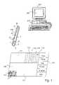
- FIG. 1is a schematic view of an embodiment of an input unit arrangement according to the invention, an embodiment of a mouse pad according to the invention, and a computer with which the input unit arrangement communicates, and
- FIGS. 2 a - bschematically illustrate examples of the division of a virtual coordinate surface which is made up by the absolute position-coding pattern which codes positions on the mouse pad in FIG. 1 .
- the figureshows a mouse pad 100 , a computer 200 and an input unit 300 for the computer 200 . Together with programs in the computer 200 , the input unit 300 forms an input unit arrangement according to the invention.
- the mouse pad 100is divided into a plurality of different areas. It has a first working field 110 for relative mouse function, a second working field 111 for absolute mouse function, a scrolling field 112 , a scanner field 113 for switching to a scanner or reading pen function, a photo field 114 for switching to a photographing function, a handwriting field 115 for switching to a handwriting recording function, and a command field 120 in which a number of predetermined commands are indicated.
- An absolute position-coding pattern 150extends over the whole mouse pad 100 .
- the patternis shown greatly enlarged on only a small part of the mouse pad 100 .
- the absolute position-coding patterncan be any type which systematically codes coordinates for a large number of positions on the mouse pad 100 , so that the position of the input unit 300 can be determined regardless of where the input unit is placed on the mouse pad 100 .
- the patterncan, for example, be of the type shown in U.S. Pat. No. 5,852,434, where each position is coded by one specific symbol.
- itcan advantageously be of the type shown in the Applicant's International Patent Applications WO00/73981, PCT/SE00/01667 and PCT/SE00/01895, where each position is coded by a plurality of symbols and each symbol contributes to the coding of several positions.
- the patternis constructed of a small number of types of symbol.
- itcan be constructed of two different-sized dots which represent a one and a zero respectively or of a dot which can have four different positions in relation to a raster point and in this way can code four different values.
- the figureshows the position-coding pattern on the mouse pad 100 constructed of symbols in the form of dots D of two different sizes. These represent a one and a zero respectively. A number of such symbols, for example 5 ⁇ 5 dots, combine to code a position on the mouse pad 100 . Each position is in this context given by at least two coordinates.
- the input unit arrangementhas a mouse function mode and an input function mode.
- the mouse function modeincludes, as partial functions, the relative mouse function, the absolute mouse function, the scrolling function and the control function.
- the input function modeincludes, as partial functions, the scanner function, the photographing function and the handwriting recording function.
- the input unit 300has a casing 1 in the shape of a pen.
- One short side of the casing 1has a window 2 through which images are recorded for different image-based functions of the input unit 300 .
- the casing 1contains principally an optics part, an electronic part and a power supply.
- the optics partcomprises a plurality of light-emitting diodes 6 , a lens system 7 and an optical sensor 8 which constitutes the interface with the electronic part.
- the light-emitting diodes 6are intended to illuminate a surface of the base which is then below the window.
- the lens system 7is intended to project an image of the surface which is below the window 2 onto the light-sensitive sensor 8 in as correct a way as possible.
- the optical sensor 8can consist of an area sensor, such as a CMOS sensor or a CCD sensor with built-in A/D converter. Such sensors are commercially available.
- the power supply for the input unitis obtained from a battery 12 , but can alternatively be obtained from a mains connection (not shown).
- the electronic partcomprises a processor 20 with conventional associated circuits, such as various types of memory, and associated programs for carrying out the functions described here.
- the processor 20forms part of the input unit arrangement's signal-processing device.
- the processor 20is wholly or partly replaced by a specially adapted hardware circuit, such as an ASIC or FPGA.
- the electronic partalso comprises a transceiver 26 for transmitting information to/from the computer 200 .
- the transceiver 26can be based on infrared technology, ultrasonics or radio technology for transmission over short distances, for example in accordance with the Bluetooth standard.
- the electronic partfurther comprises buttons 27 , by means of which the user can control the input unit, for example switch it on and off.
- the computer 200is an ordinary personal computer with circuits and programs which make possible communication with the input unit 300 . However, in this embodiment this also contains software which constitutes part of the input unit arrangement's signal-processing device.
- the softwarestores information about which functions are associated with different regions of the position-coding pattern.
- the softwareis shown symbolically by broken lines and reference numeral 210 .
- the input unit arrangementhas a mouse function mode and an input function mode, including, inter alia, a scanner function.
- the scanner functionis used to record text.
- the scanner functioncan be of the type described in the Applicant's Patent Publication WO98/20446, where text is recorded by recording a plurality of images with partially overlapping content and putting them together, after which the characters in the put-together image are localized, identified and stored in character-coded format.
- the scanner functioncan alternatively be used to input image information.
- the mouse function modeis used to control a cursor on the display 201 of a computer 200 and to give different commands to the computer 200 .
- the mouse function modeis also image-based and is achieved as follows.
- the sensor 8records images at a predetermined frequency. Each image reproduces part of the position-coding pattern on the mouse pad 100 , which part is sufficiently large for the processor 20 to be able to determine the position of the input unit 300 on the mouse pad 100 .
- the processor 20localizes the symbols of which the position-coding pattern is constructed in each image, translates the symbols into coordinates according to pre-determined rules and sends the coordinates to the computer 200 via the transceiver 26 .
- the software 210interprets the coordinates and converts these into positioning signals for a cursor on the display 201 of the computer.
- the arrangement described aboveis used in the following way.
- the userwants to use the input unit 300 as an ordinary relative mouse. He places the input unit 300 in the first working field 110 .
- the processor 20detects the coordinates in the image recorded by the sensor 8 , switches the input unit 300 to the mouse function mode and sends the coordinates to the computer 200 , in which the software 210 detects that the coordinates belong to the working field 110 and that they are therefore to be interpreted as belonging to the relative mouse function.
- the software 210receives coordinates which belong to the working field 110 it will generate commands to the computer 200 for moving the cursor on the screen 201 in a corresponding way to the way the user has moved the input unit 300 over the working field 110 .
- the working field 111 for absolute mouse functioncan be used in a corresponding way, with the difference that the software 210 maps absolute positions in the working field 111 to absolute positions of the cursor on the computer screen 201 .
- the useredits a document in the computer 200 . He can mark text in the same way as with a traditional mouse by “clicking” with the buttons 27 . Assume that the user first wants to replace a first piece of text with a second piece of text which is situated elsewhere in the text. The user presses one of the buttons 27 and moves the input unit 300 over the second piece of text for marking thereof. Then he places the input unit 300 on the mouse pad 100 in that part of the command field 120 which is labeled with the command “cut”.
- the input unit 300then sends the coordinates read from this partial field to the software 210 in the computer 200 which identifies that the coordinates represent the command “cut” and creates the corresponding command for the word-processing application concerned, which cuts out the marked piece of text.
- the usernext marks the first piece of text using the input unit 300 and then causes the computer 200 to paste the cut-out piece of text in place of the marked text by reading the coordinates for the command “paste” using the input unit 300 .
- the usercan himself define which functions are to be implemented upon the detection of coordinates within various coordinate areas, for example the one marked “user-defined” on the mouse pad 100 . This can be carried out by means of the software 210 .
- the usercan carry out a number of functions in a convenient way by means of just one input unit 300 which reads coordinates on a mouse pad 100 .
- One more exampleis a photographing function which allows recording of individual images at a distance from the input unit 300 .
- the input unit 300records at least one position in the photo field 114 of the mouse pad 100
- the input unit 300switches to the photographing function, in which the user, by pressing one of the buttons 27 , can capture images of the surroundings.
- the lens systemmust be adjusted so that a sharp image on the sensor 8 is obtained at an infinite distance, or normally a distance of about two meters.
- the lens system 7is adjusted in such manner that a sharp image is obtained of an object which is positioned at the window 2 , i.e. normally about two centimeters from the sensor 8 .
- the input unit 300can be programmed to reset from the photographing function to a standard function (default), such as the scanner function, after a predetermined period of time has passed, for instance after a few minutes.
- the embodiment in FIG. 1also comprises a handwriting recording function which allows recording of handwritten text. Examples of such handwriting recording are disclosed in WO99/60467.
- the input unit 300records a position in the handwriting field 115 , it switches to the handwriting recording function, in which the user can enter information by moving the input unit over the working field 110 .
- the mouse pad 100may comprise a working field (not shown) which is dedicated to recording of handwriting and within which information is written by means of the input unit 300 .
- the input unit 300is switched between different function positions.
- the input unit 300When the input unit 300 is in the mouse position, it generates a sequence of coordinates to the software in the computer, regardless of whether the arrangement is intended to operate with relative mouse function, absolute mouse function, scrolling function or control function.
- the software 210then analyzes the received coordinates and executes adequate mouse functions on the basis thereof.
- the input unit 300In the photo position, the input unit 300 generates individual images while in the text inputting position, it performs character recognition (OCR) and then generates character-coded text, and in the handwriting position the input unit 300 generates either a sequence of coordinates forming a graphical trace of the handwriting or a version of the handwriting, which is subjected to character recognition (ICR).
- OCRcharacter recognition
- the switching of the input unit 300implies that its processor 20 must contain at least certain information about the coordinate areas which are associated with various functions.
- the use of a position-coding patternallows the input unit 300 , while demanding a small amount of processor power and storage capacity, to identify different function positions based on the detected coordinates.
- the input unit 300need only detect coordinates within the main region in order to switch to the mouse position.
- FIG. 2 aschematically shows a virtual coordinate surface 400 which is made up by all positions which the absolute position-coding pattern has the capacity to code.
- a first main region 405 on the virtual surface 400is dedicated to the mouse function mode.
- the main region 405comprises a subregion 410 dedicated to the relative mouse function, a subregion 411 dedicated to the absolute mouse function, a subregion 412 dedicated to the scrolling function and a subregion 420 which is in turn additionally segmented and dedicated to the control function.
- a second main region 406 on the virtual surface 400is dedicated to the input function mode and comprises a subregion 413 dedicated to the scanner function, a subregion 414 dedicated to the photographing function and a subregion 415 dedicated to the handwriting recording function.
- FIG. 2Bshows schematically another example of the division of the virtual coordinate surface 400 , where the different subregions 410 - 420 are not included in superordinate, coherent main regions.
- the mouse pad 100 in FIG. 1is thus provided with parts of the absolute position-coding pattern, more specifically the parts coding positions within selected coordinate areas 410 - 420 on the virtual surface 400 .
- the arrangementis automatically switched to the function which is associated with the position which is coded by the pattern in the last recorded image.
- the arrangementcan be arranged in such manner that certain functions are connected statically and other functions are connected dynamically. More specifically, the mouse function mode can be connected only as long as associated positions are detected, i.e. dynamically, while the arrangement remains connected in the scanner function and the photographing function also when the input unit is raised from the mouse pad, i.e. these functions are connected statically. This means that the arrangement is automatically switched back to the last static function, whereby the user's managing of the arrangement is facilitated. In an alternative, it is however conceivable for all functions to be connected statically.
- the input unit arrangementneed not have both an input function mode and a mouse function mode. It can have a mouse function mode only, in which case the reading of the coordinates on the mouse pad is used in the same way as above, but of course without switching to an input function mode.
- the input unit arrangementis switched between arbitrary functions when detecting a predetermined position-coding pattern.
- a switching of the input unit between different function positionstakes place on the basis of the detected coordinates, while the software in the computer carries out the switching between different partial functions within the scope of the mouse function mode.
- the operations of the arrangementcan, however, take place, arbitrarily distributed among the input unit and the computer.
- all processingtakes place in the input unit, which generates control commands and/or processed data to the computer.
- character recognition and similar subsequent processingcan be located in the computer, which as a rule has more processor power and storage capacity than the input unit.
- the input unitis only arranged to output the recorded images to the computer, in which the software detects coordinates and switches the arrangement between different functions.
- the input unit arrangementcan communicate with other types of computer-based devices, for instance a PDA or a mobile phone.
Landscapes
- Engineering & Computer Science (AREA)
- General Engineering & Computer Science (AREA)
- Theoretical Computer Science (AREA)
- Human Computer Interaction (AREA)
- Physics & Mathematics (AREA)
- General Physics & Mathematics (AREA)
- Position Input By Displaying (AREA)
Abstract
Description
Claims (24)
Priority Applications (1)
| Application Number | Priority Date | Filing Date | Title |
|---|---|---|---|
| US11/226,428US7345673B2 (en) | 2000-02-18 | 2005-09-15 | Input unit arrangement |
Applications Claiming Priority (8)
| Application Number | Priority Date | Filing Date | Title |
|---|---|---|---|
| SE0000541ASE0000541L (en) | 2000-02-18 | 2000-02-18 | Electronic device control |
| SE0000541-3 | 2000-02-18 | ||
| SE0000939ASE0000939L (en) | 2000-02-18 | 2000-03-21 | Inenhetsarrangemang |
| SE0000939-9 | 2000-03-21 | ||
| US20816900P | 2000-05-31 | 2000-05-31 | |
| US20816400P | 2000-05-31 | 2000-05-31 | |
| US09/784,551US6992655B2 (en) | 2000-02-18 | 2001-02-16 | Input unit arrangement |
| US11/226,428US7345673B2 (en) | 2000-02-18 | 2005-09-15 | Input unit arrangement |
Related Parent Applications (1)
| Application Number | Title | Priority Date | Filing Date |
|---|---|---|---|
| US09/784,551DivisionUS6992655B2 (en) | 2000-02-18 | 2001-02-16 | Input unit arrangement |
Publications (2)
| Publication Number | Publication Date |
|---|---|
| US20060007183A1 US20060007183A1 (en) | 2006-01-12 |
| US7345673B2true US7345673B2 (en) | 2008-03-18 |
Family
ID=27532709
Family Applications (2)
| Application Number | Title | Priority Date | Filing Date |
|---|---|---|---|
| US09/784,551Expired - LifetimeUS6992655B2 (en) | 2000-02-18 | 2001-02-16 | Input unit arrangement |
| US11/226,428Expired - Fee RelatedUS7345673B2 (en) | 2000-02-18 | 2005-09-15 | Input unit arrangement |
Family Applications Before (1)
| Application Number | Title | Priority Date | Filing Date |
|---|---|---|---|
| US09/784,551Expired - LifetimeUS6992655B2 (en) | 2000-02-18 | 2001-02-16 | Input unit arrangement |
Country Status (1)
| Country | Link |
|---|---|
| US (2) | US6992655B2 (en) |
Cited By (27)
| Publication number | Priority date | Publication date | Assignee | Title |
|---|---|---|---|---|
| US20060209175A1 (en)* | 2005-03-18 | 2006-09-21 | Searete Llc, A Limited Liability Corporation Of The State Of Delaware | Electronic association of a user expression and a context of the expression |
| US20060209043A1 (en)* | 2005-03-18 | 2006-09-21 | Searete Llc, A Limited Liability Corporation Of The State Of Delaware | Machine-differentiatable identifiers having a commonly accepted meaning |
| US20060212430A1 (en)* | 2005-03-18 | 2006-09-21 | Searete Llc, A Limited Liability Corporation Of The State Of Delaware | Outputting a saved hand-formed expression |
| US20060209051A1 (en)* | 2005-03-18 | 2006-09-21 | Searete Llc, A Limited Liability Corporation Of The State Of Delaware | Electronic acquisition of a hand formed expression and a context of the expression |
| US20060208085A1 (en)* | 2005-03-18 | 2006-09-21 | Searete Llc, A Limited Liability Corporation Of The State Of Delaware | Acquisition of a user expression and a context of the expression |
| US20060267964A1 (en)* | 2005-05-25 | 2006-11-30 | Searete Llc, A Limited Liability Corporation Of The State Of Delaware | Performing an action with respect to hand-formed expression |
| US20070075989A1 (en)* | 2005-03-18 | 2007-04-05 | Searete Llc, A Limited Liability Corporation Of The State Of Delaware | Electronic acquisition of a hand formed expression and a context of the expression |
| US20070120837A1 (en)* | 2005-03-18 | 2007-05-31 | Searete Llc, A Limited Liability Corporation Of The State Of Delaware | Including environmental information in a manual expression |
| US20070126717A1 (en)* | 2005-03-18 | 2007-06-07 | Searete Llc, A Limited Liability Corporation Of The State Of Delaware | Including contextual information with a formed expression |
| US20070273674A1 (en)* | 2005-03-18 | 2007-11-29 | Searete Llc, A Limited Liability Corporation | Machine-differentiatable identifiers having a commonly accepted meaning |
| US20080088604A1 (en)* | 2006-10-11 | 2008-04-17 | Searete Llc, A Limited Liability Corporation | Contextual information encoded in a formed expression |
| US20080180412A1 (en)* | 2007-01-31 | 2008-07-31 | Microsoft Corporation | Dual mode digitizer |
| US8712193B2 (en) | 2000-11-06 | 2014-04-29 | Nant Holdings Ip, Llc | Image capture and identification system and process |
| US8792750B2 (en) | 2000-11-06 | 2014-07-29 | Nant Holdings Ip, Llc | Object information derived from object images |
| US8824738B2 (en) | 2000-11-06 | 2014-09-02 | Nant Holdings Ip, Llc | Data capture and identification system and process |
| US9170449B2 (en) | 2013-01-28 | 2015-10-27 | Samsung Display Co., Ltd. | Display device |
| US9310892B2 (en) | 2000-11-06 | 2016-04-12 | Nant Holdings Ip, Llc | Object information derived from object images |
| US10380920B2 (en) | 2013-09-23 | 2019-08-13 | SonoSim, Inc. | System and method for augmented ultrasound simulation using flexible touch sensitive surfaces |
| US10617568B2 (en) | 2000-11-06 | 2020-04-14 | Nant Holdings Ip, Llc | Image capture and identification system and process |
| US11315439B2 (en) | 2013-11-21 | 2022-04-26 | SonoSim, Inc. | System and method for extended spectrum ultrasound training using animate and inanimate training objects |
| US11495142B2 (en) | 2019-01-30 | 2022-11-08 | The Regents Of The University Of California | Ultrasound trainer with internal optical tracking |
| US11600201B1 (en) | 2015-06-30 | 2023-03-07 | The Regents Of The University Of California | System and method for converting handheld diagnostic ultrasound systems into ultrasound training systems |
| US11631342B1 (en) | 2012-05-25 | 2023-04-18 | The Regents Of University Of California | Embedded motion sensing technology for integration within commercial ultrasound probes |
| US11627944B2 (en) | 2004-11-30 | 2023-04-18 | The Regents Of The University Of California | Ultrasound case builder system and method |
| US11749137B2 (en) | 2017-01-26 | 2023-09-05 | The Regents Of The University Of California | System and method for multisensory psychomotor skill training |
| US11810473B2 (en) | 2019-01-29 | 2023-11-07 | The Regents Of The University Of California | Optical surface tracking for medical simulation |
| US12399923B1 (en) | 2023-09-15 | 2025-08-26 | Gabriele Nataneli | Multi-modal enhancement of large language models without retraining |
Families Citing this family (98)
| Publication number | Priority date | Publication date | Assignee | Title |
|---|---|---|---|---|
| US8352400B2 (en) | 1991-12-23 | 2013-01-08 | Hoffberg Steven M | Adaptive pattern recognition based controller apparatus and method and human-factored interface therefore |
| US7904187B2 (en) | 1999-02-01 | 2011-03-08 | Hoffberg Steven M | Internet appliance system and method |
| US7091959B1 (en)* | 1999-03-31 | 2006-08-15 | Advanced Digital Systems, Inc. | System, computer program product, computing device, and associated methods for form identification and information manipulation |
| SE517445C2 (en)* | 1999-10-01 | 2002-06-04 | Anoto Ab | Position determination on a surface provided with a position coding pattern |
| AU772145B2 (en)* | 1999-10-25 | 2004-04-08 | Silverbrook Research Pty Ltd | Electronically controllable pen |
| US20030061188A1 (en)* | 1999-12-23 | 2003-03-27 | Linus Wiebe | General information management system |
| US20060082557A1 (en)* | 2000-04-05 | 2006-04-20 | Anoto Ip Lic Hb | Combined detection of position-coding pattern and bar codes |
| JP2002150306A (en)* | 2000-09-04 | 2002-05-24 | Minolta Co Ltd | Image processing device, image processing method, image processing program, and computer-readable recording medium with image processing program recorded thereon |
| US6798907B1 (en)* | 2001-01-24 | 2004-09-28 | Advanced Digital Systems, Inc. | System, computer software product and method for transmitting and processing handwritten data |
| US20020107885A1 (en)* | 2001-02-01 | 2002-08-08 | Advanced Digital Systems, Inc. | System, computer program product, and method for capturing and processing form data |
| US7916124B1 (en) | 2001-06-20 | 2011-03-29 | Leapfrog Enterprises, Inc. | Interactive apparatus using print media |
| SE0102210L (en)* | 2001-06-21 | 2003-02-12 | Anoto Ab | Program control procedure |
| KR20030050741A (en)* | 2001-12-19 | 2003-06-25 | 삼성전자주식회사 | Method for inputting character fast and easily in portable device having limited display size and number of key, and Portable device using the same |
| AU2012202678B2 (en)* | 2002-09-26 | 2015-07-16 | Kenji Yoshida | Information reproduction i/o method using dot pattern, information reproduction device, mobile information i/o device, and electronic toy |
| US7133563B2 (en)* | 2002-10-31 | 2006-11-07 | Microsoft Corporation | Passive embedded interaction code |
| US7116840B2 (en) | 2002-10-31 | 2006-10-03 | Microsoft Corporation | Decoding and error correction in 2-D arrays |
| SE523298C2 (en)* | 2002-11-19 | 2004-04-06 | Tetra Laval Holdings & Finance | Methods of transferring information from a plant for the manufacture of packaging material to a filling machine, ways of providing a packaging material with information, and packaging material and its use 2805 |
| US20040239615A1 (en)* | 2003-05-27 | 2004-12-02 | International Business Machines Corporation | System and method for providing a computer user with alerts using a lighted mouse pad |
| US20050060644A1 (en)* | 2003-09-15 | 2005-03-17 | Patterson John Douglas | Real time variable digital paper |
| US20050117911A1 (en)* | 2003-11-27 | 2005-06-02 | John Hsuan | Multifunctional optical device |
| US7583842B2 (en)* | 2004-01-06 | 2009-09-01 | Microsoft Corporation | Enhanced approach of m-array decoding and error correction |
| US7263224B2 (en)* | 2004-01-16 | 2007-08-28 | Microsoft Corporation | Strokes localization by m-array decoding and fast image matching |
| US8442331B2 (en)* | 2004-02-15 | 2013-05-14 | Google Inc. | Capturing text from rendered documents using supplemental information |
| US7707039B2 (en)* | 2004-02-15 | 2010-04-27 | Exbiblio B.V. | Automatic modification of web pages |
| US8799303B2 (en)* | 2004-02-15 | 2014-08-05 | Google Inc. | Establishing an interactive environment for rendered documents |
| US20060041484A1 (en) | 2004-04-01 | 2006-02-23 | King Martin T | Methods and systems for initiating application processes by data capture from rendered documents |
| US20060136629A1 (en)* | 2004-08-18 | 2006-06-22 | King Martin T | Scanner having connected and unconnected operational behaviors |
| US7812860B2 (en)* | 2004-04-01 | 2010-10-12 | Exbiblio B.V. | Handheld device for capturing text from both a document printed on paper and a document displayed on a dynamic display device |
| US10635723B2 (en) | 2004-02-15 | 2020-04-28 | Google Llc | Search engines and systems with handheld document data capture devices |
| US7831933B2 (en) | 2004-03-17 | 2010-11-09 | Leapfrog Enterprises, Inc. | Method and system for implementing a user interface for a device employing written graphical elements |
| US20060125805A1 (en)* | 2004-03-17 | 2006-06-15 | James Marggraff | Method and system for conducting a transaction using recognized text |
| US7853193B2 (en)* | 2004-03-17 | 2010-12-14 | Leapfrog Enterprises, Inc. | Method and device for audibly instructing a user to interact with a function |
| US20060033725A1 (en)* | 2004-06-03 | 2006-02-16 | Leapfrog Enterprises, Inc. | User created interactive interface |
| US20080313172A1 (en)* | 2004-12-03 | 2008-12-18 | King Martin T | Determining actions involving captured information and electronic content associated with rendered documents |
| US7894670B2 (en) | 2004-04-01 | 2011-02-22 | Exbiblio B.V. | Triggering actions in response to optically or acoustically capturing keywords from a rendered document |
| US8146156B2 (en) | 2004-04-01 | 2012-03-27 | Google Inc. | Archive of text captures from rendered documents |
| US20070300142A1 (en)* | 2005-04-01 | 2007-12-27 | King Martin T | Contextual dynamic advertising based upon captured rendered text |
| US8081849B2 (en)* | 2004-12-03 | 2011-12-20 | Google Inc. | Portable scanning and memory device |
| US9143638B2 (en) | 2004-04-01 | 2015-09-22 | Google Inc. | Data capture from rendered documents using handheld device |
| US9008447B2 (en)* | 2004-04-01 | 2015-04-14 | Google Inc. | Method and system for character recognition |
| US9116890B2 (en) | 2004-04-01 | 2015-08-25 | Google Inc. | Triggering actions in response to optically or acoustically capturing keywords from a rendered document |
| US8793162B2 (en)* | 2004-04-01 | 2014-07-29 | Google Inc. | Adding information or functionality to a rendered document via association with an electronic counterpart |
| US20100185538A1 (en)* | 2004-04-01 | 2010-07-22 | Exbiblio B.V. | Content access with handheld document data capture devices |
| US8621349B2 (en)* | 2004-04-01 | 2013-12-31 | Google Inc. | Publishing techniques for adding value to a rendered document |
| US7990556B2 (en) | 2004-12-03 | 2011-08-02 | Google Inc. | Association of a portable scanner with input/output and storage devices |
| US20060081714A1 (en) | 2004-08-23 | 2006-04-20 | King Martin T | Portable scanning device |
| US20060098900A1 (en) | 2004-09-27 | 2006-05-11 | King Martin T | Secure data gathering from rendered documents |
| US8713418B2 (en)* | 2004-04-12 | 2014-04-29 | Google Inc. | Adding value to a rendered document |
| US8620083B2 (en) | 2004-12-03 | 2013-12-31 | Google Inc. | Method and system for character recognition |
| US8874504B2 (en)* | 2004-12-03 | 2014-10-28 | Google Inc. | Processing techniques for visual capture data from a rendered document |
| US8489624B2 (en) | 2004-05-17 | 2013-07-16 | Google, Inc. | Processing techniques for text capture from a rendered document |
| US9460346B2 (en) | 2004-04-19 | 2016-10-04 | Google Inc. | Handheld device for capturing text from both a document printed on paper and a document displayed on a dynamic display device |
| US7656395B2 (en)* | 2004-07-15 | 2010-02-02 | Microsoft Corporation | Methods and apparatuses for compound tracking systems |
| US8346620B2 (en) | 2004-07-19 | 2013-01-01 | Google Inc. | Automatic modification of web pages |
| US7733326B1 (en) | 2004-08-02 | 2010-06-08 | Prakash Adiseshan | Combination mouse, pen-input and pen-computer device |
| US20100092095A1 (en)* | 2008-10-14 | 2010-04-15 | Exbiblio B.V. | Data gathering in digital and rendered document environments |
| US20110075228A1 (en)* | 2004-12-03 | 2011-03-31 | King Martin T | Scanner having connected and unconnected operational behaviors |
| US7639876B2 (en)* | 2005-01-14 | 2009-12-29 | Advanced Digital Systems, Inc. | System and method for associating handwritten information with one or more objects |
| US7607076B2 (en) | 2005-02-18 | 2009-10-20 | Microsoft Corporation | Embedded interaction code document |
| US7826074B1 (en) | 2005-02-25 | 2010-11-02 | Microsoft Corporation | Fast embedded interaction code printing with custom postscript commands |
| US20060215913A1 (en)* | 2005-03-24 | 2006-09-28 | Microsoft Corporation | Maze pattern analysis with image matching |
| US7421439B2 (en) | 2005-04-22 | 2008-09-02 | Microsoft Corporation | Global metadata embedding and decoding |
| US7599560B2 (en) | 2005-04-22 | 2009-10-06 | Microsoft Corporation | Embedded interaction code recognition |
| US20060242562A1 (en)* | 2005-04-22 | 2006-10-26 | Microsoft Corporation | Embedded method for embedded interaction code array |
| US7720286B2 (en)* | 2005-05-25 | 2010-05-18 | Advanced Digital Systems, Inc. | System and method for associating handwritten information with one or more objects via discontinuous regions of a printed pattern |
| US7400777B2 (en)* | 2005-05-25 | 2008-07-15 | Microsoft Corporation | Preprocessing for information pattern analysis |
| US7729539B2 (en)* | 2005-05-31 | 2010-06-01 | Microsoft Corporation | Fast error-correcting of embedded interaction codes |
| US7580576B2 (en)* | 2005-06-02 | 2009-08-25 | Microsoft Corporation | Stroke localization and binding to electronic document |
| US7619607B2 (en) | 2005-06-30 | 2009-11-17 | Microsoft Corporation | Embedding a pattern design onto a liquid crystal display |
| US7922099B1 (en) | 2005-07-29 | 2011-04-12 | Leapfrog Enterprises, Inc. | System and method for associating content with an image bearing surface |
| US7622182B2 (en) | 2005-08-17 | 2009-11-24 | Microsoft Corporation | Embedded interaction code enabled display |
| US7817816B2 (en)* | 2005-08-17 | 2010-10-19 | Microsoft Corporation | Embedded interaction code enabled surface type identification |
| US20090127006A1 (en)* | 2005-11-11 | 2009-05-21 | Stefan Lynggaard | Information Management in an Electronic Pen Arrangement |
| US8599143B1 (en) | 2006-02-06 | 2013-12-03 | Leapfrog Enterprises, Inc. | Switch configuration for detecting writing pressure in a writing device |
| JP4042065B1 (en)* | 2006-03-10 | 2008-02-06 | 健治 吉田 | Input processing system for information processing device |
| CN100381997C (en)* | 2006-04-29 | 2008-04-16 | 怡利电子工业股份有限公司 | Menu selection method of touch key |
| EP2035909A1 (en)* | 2006-06-16 | 2009-03-18 | Khaled A. Kaladeh | Interactive printed position coded pattern whiteboard |
| US8261967B1 (en) | 2006-07-19 | 2012-09-11 | Leapfrog Enterprises, Inc. | Techniques for interactively coupling electronic content with printed media |
| EP2067119A2 (en) | 2006-09-08 | 2009-06-10 | Exbiblio B.V. | Optical scanners, such as hand-held optical scanners |
| WO2008031625A2 (en)* | 2006-09-15 | 2008-03-20 | Exbiblio B.V. | Capture and display of annotations in paper and electronic documents |
| US11449158B2 (en)* | 2006-12-28 | 2022-09-20 | International Business Machines Corporation | Interactive, touch-sensitive user interface device |
| WO2008095228A1 (en)* | 2007-02-08 | 2008-08-14 | Silverbrook Research Pty Ltd | Method of sensing motion of a sensing device relative to a surface |
| TW200919298A (en)* | 2007-08-01 | 2009-05-01 | Silverbrook Res Pty Ltd | Interactive handheld scanner |
| US20110145068A1 (en)* | 2007-09-17 | 2011-06-16 | King Martin T | Associating rendered advertisements with digital content |
| US20090078473A1 (en)* | 2007-09-26 | 2009-03-26 | Digital Pen Systems | Handwriting Capture For Determining Absolute Position Within A Form Layout Using Pen Position Triangulation |
| KR101717101B1 (en)* | 2007-12-12 | 2017-03-27 | 가부시키가이샤 아이피 솔루션즈 | Information input device, information processing device, information input system, information processing system, two-dimensional format information server, information input method, control program, and recording medium |
| DE202010018601U1 (en)* | 2009-02-18 | 2018-04-30 | Google LLC (n.d.Ges.d. Staates Delaware) | Automatically collecting information, such as gathering information using a document recognizing device |
| US8447066B2 (en) | 2009-03-12 | 2013-05-21 | Google Inc. | Performing actions based on capturing information from rendered documents, such as documents under copyright |
| CN102349087B (en) | 2009-03-12 | 2015-05-06 | 谷歌公司 | Automatically provide content associated with captured information, such as information captured in real time |
| US9081799B2 (en)* | 2009-12-04 | 2015-07-14 | Google Inc. | Using gestalt information to identify locations in printed information |
| US9323784B2 (en)* | 2009-12-09 | 2016-04-26 | Google Inc. | Image search using text-based elements within the contents of images |
| GB2480602A (en)* | 2010-05-24 | 2011-11-30 | Shahar Nitzan | Orientation surfaces and uses thereof |
| TWI420351B (en)* | 2010-12-13 | 2013-12-21 | Hon Hai Prec Ind Co Ltd | Electronic reading device |
| US20140225827A1 (en)* | 2011-09-22 | 2014-08-14 | Hewlett-Packard Development Company, L.P. | Soft button input systems and methods |
| JP2015187830A (en) | 2014-03-12 | 2015-10-29 | パナソニックIpマネジメント株式会社 | display control system |
| US10852856B2 (en)* | 2017-03-14 | 2020-12-01 | Hades-Gaming Corp. | Computer input apparatus and input method thereof |
| US20200097096A1 (en)* | 2017-06-16 | 2020-03-26 | Hewlett-Packard Development Company, L.P. | Displaying images from multiple devices |
| US11046182B2 (en)* | 2018-10-22 | 2021-06-29 | Nio Usa, Inc. | System and method for providing momentum scrolling via a rotary user interface device |
Citations (31)
| Publication number | Priority date | Publication date | Assignee | Title |
|---|---|---|---|---|
| US4804949A (en)* | 1987-03-20 | 1989-02-14 | Everex Ti Corporation | Hand-held optical scanner and computer mouse |
| US4814553A (en) | 1985-06-21 | 1989-03-21 | Advanced Robotic Technology, Inc. | Absolute position controller |
| US5294792A (en) | 1991-12-31 | 1994-03-15 | Texas Instruments Incorporated | Writing tip position sensing and processing apparatus |
| US5661506A (en) | 1994-11-10 | 1997-08-26 | Sia Technology Corporation | Pen and paper information recording system using an imaging pen |
| WO1998020446A1 (en) | 1996-11-01 | 1998-05-14 | C Technologies Ab | Recording method and apparatus |
| US5852434A (en)* | 1992-04-03 | 1998-12-22 | Sekendur; Oral F. | Absolute optical position determination |
| US5856822A (en) | 1995-10-27 | 1999-01-05 | 02 Micro, Inc. | Touch-pad digital computer pointing-device |
| US5932863A (en) | 1994-05-25 | 1999-08-03 | Rathus; Spencer A. | Method and apparatus for accessing electric data via a familiar printed medium |
| WO1999050787A1 (en) | 1998-04-01 | 1999-10-07 | Xerox Corporation | Cross-network functions via linked hardcopy and electronic documents |
| WO1999056200A1 (en) | 1998-04-28 | 1999-11-04 | Alop Electronics Co., Ltd. | Data input device and method, and computer system using the same and method for running program of computer system |
| WO1999060468A1 (en) | 1998-04-30 | 1999-11-25 | C Technologies Ab | Input unit, method for using the same and input system |
| WO1999060467A1 (en) | 1998-04-30 | 1999-11-25 | C Technologies Ab | Device and method for recording hand-written information |
| WO2000008593A2 (en) | 1998-08-07 | 2000-02-17 | Thomas Teufel | Combined mouse |
| WO2000025293A1 (en) | 1998-10-23 | 2000-05-04 | Raphael Cohen | Pen-input device |
| US6061051A (en) | 1997-01-17 | 2000-05-09 | Tritech Microelectronics | Command set for touchpad pen-input mouse |
| US6128007A (en)* | 1996-07-29 | 2000-10-03 | Motorola, Inc. | Method and apparatus for multi-mode handwritten input and hand directed control of a computing device |
| WO2000073981A1 (en) | 1999-05-28 | 2000-12-07 | Anoto Ab | Recording of information |
| WO2001016691A1 (en) | 1999-08-30 | 2001-03-08 | Anoto Ab | Notepad |
| WO2001026032A1 (en) | 1999-10-01 | 2001-04-12 | Anoto Ab | Encoded paper for optical reading |
| WO2001061635A2 (en) | 2000-02-16 | 2001-08-23 | Telefonaktiebolaget L M Ericsson (Publ) | Method and system for configuring and unlocking an electronic reading device |
| US6310988B1 (en) | 1996-12-20 | 2001-10-30 | Xerox Parc | Methods and apparatus for camera pen |
| US20010035861A1 (en) | 2000-02-18 | 2001-11-01 | Petter Ericson | Controlling and electronic device |
| US6392632B1 (en)* | 1998-12-08 | 2002-05-21 | Windbond Electronics, Corp. | Optical mouse having an integrated camera |
| US20020091711A1 (en) | 1999-08-30 | 2002-07-11 | Petter Ericson | Centralized information management |
| US6498604B1 (en)* | 1997-02-12 | 2002-12-24 | Kanitech A/S | Input device for a computer |
| US6502756B1 (en) | 1999-05-28 | 2003-01-07 | Anoto Ab | Recording of information |
| US20030046256A1 (en) | 1999-12-23 | 2003-03-06 | Ola Hugosson | Distributed information management |
| US20030061188A1 (en) | 1999-12-23 | 2003-03-27 | Linus Wiebe | General information management system |
| US6567120B1 (en) | 1996-10-14 | 2003-05-20 | Nikon Corporation | Information processing apparatus having a photographic mode and a memo input mode |
| US6603464B1 (en)* | 2000-03-03 | 2003-08-05 | Michael Irl Rabin | Apparatus and method for record keeping and information distribution |
| US6906699B1 (en)* | 1998-04-30 | 2005-06-14 | C Technologies Ab | Input unit, method for using the same and input system |
Family Cites Families (1)
| Publication number | Priority date | Publication date | Assignee | Title |
|---|---|---|---|---|
| US529792A (en)* | 1894-11-27 | Thomas anderson hodgson |
- 2001
- 2001-02-16USUS09/784,551patent/US6992655B2/ennot_activeExpired - Lifetime
- 2005
- 2005-09-15USUS11/226,428patent/US7345673B2/ennot_activeExpired - Fee Related
Patent Citations (31)
| Publication number | Priority date | Publication date | Assignee | Title |
|---|---|---|---|---|
| US4814553A (en) | 1985-06-21 | 1989-03-21 | Advanced Robotic Technology, Inc. | Absolute position controller |
| US4804949A (en)* | 1987-03-20 | 1989-02-14 | Everex Ti Corporation | Hand-held optical scanner and computer mouse |
| US5294792A (en) | 1991-12-31 | 1994-03-15 | Texas Instruments Incorporated | Writing tip position sensing and processing apparatus |
| US5852434A (en)* | 1992-04-03 | 1998-12-22 | Sekendur; Oral F. | Absolute optical position determination |
| US5932863A (en) | 1994-05-25 | 1999-08-03 | Rathus; Spencer A. | Method and apparatus for accessing electric data via a familiar printed medium |
| US5661506A (en) | 1994-11-10 | 1997-08-26 | Sia Technology Corporation | Pen and paper information recording system using an imaging pen |
| US5856822A (en) | 1995-10-27 | 1999-01-05 | 02 Micro, Inc. | Touch-pad digital computer pointing-device |
| US6128007A (en)* | 1996-07-29 | 2000-10-03 | Motorola, Inc. | Method and apparatus for multi-mode handwritten input and hand directed control of a computing device |
| US6567120B1 (en) | 1996-10-14 | 2003-05-20 | Nikon Corporation | Information processing apparatus having a photographic mode and a memo input mode |
| WO1998020446A1 (en) | 1996-11-01 | 1998-05-14 | C Technologies Ab | Recording method and apparatus |
| US6310988B1 (en) | 1996-12-20 | 2001-10-30 | Xerox Parc | Methods and apparatus for camera pen |
| US6061051A (en) | 1997-01-17 | 2000-05-09 | Tritech Microelectronics | Command set for touchpad pen-input mouse |
| US6498604B1 (en)* | 1997-02-12 | 2002-12-24 | Kanitech A/S | Input device for a computer |
| WO1999050787A1 (en) | 1998-04-01 | 1999-10-07 | Xerox Corporation | Cross-network functions via linked hardcopy and electronic documents |
| WO1999056200A1 (en) | 1998-04-28 | 1999-11-04 | Alop Electronics Co., Ltd. | Data input device and method, and computer system using the same and method for running program of computer system |
| WO1999060468A1 (en) | 1998-04-30 | 1999-11-25 | C Technologies Ab | Input unit, method for using the same and input system |
| US6906699B1 (en)* | 1998-04-30 | 2005-06-14 | C Technologies Ab | Input unit, method for using the same and input system |
| WO1999060467A1 (en) | 1998-04-30 | 1999-11-25 | C Technologies Ab | Device and method for recording hand-written information |
| WO2000008593A2 (en) | 1998-08-07 | 2000-02-17 | Thomas Teufel | Combined mouse |
| WO2000025293A1 (en) | 1998-10-23 | 2000-05-04 | Raphael Cohen | Pen-input device |
| US6392632B1 (en)* | 1998-12-08 | 2002-05-21 | Windbond Electronics, Corp. | Optical mouse having an integrated camera |
| WO2000073981A1 (en) | 1999-05-28 | 2000-12-07 | Anoto Ab | Recording of information |
| US6502756B1 (en) | 1999-05-28 | 2003-01-07 | Anoto Ab | Recording of information |
| WO2001016691A1 (en) | 1999-08-30 | 2001-03-08 | Anoto Ab | Notepad |
| US20020091711A1 (en) | 1999-08-30 | 2002-07-11 | Petter Ericson | Centralized information management |
| WO2001026032A1 (en) | 1999-10-01 | 2001-04-12 | Anoto Ab | Encoded paper for optical reading |
| US20030061188A1 (en) | 1999-12-23 | 2003-03-27 | Linus Wiebe | General information management system |
| US20030046256A1 (en) | 1999-12-23 | 2003-03-06 | Ola Hugosson | Distributed information management |
| WO2001061635A2 (en) | 2000-02-16 | 2001-08-23 | Telefonaktiebolaget L M Ericsson (Publ) | Method and system for configuring and unlocking an electronic reading device |
| US20010035861A1 (en) | 2000-02-18 | 2001-11-01 | Petter Ericson | Controlling and electronic device |
| US6603464B1 (en)* | 2000-03-03 | 2003-08-05 | Michael Irl Rabin | Apparatus and method for record keeping and information distribution |
Non-Patent Citations (2)
| Title |
|---|
| Abstract of Japanese Patent Publication No. JP9190277, esp (C) cenet database, published Jul. 22, 1997. |
| XP002328425: Dymetman and Copperman, Intelligent Paper, Xerox Research Center Europe; published in Apr. 1998. |
Cited By (141)
| Publication number | Priority date | Publication date | Assignee | Title |
|---|---|---|---|---|
| US9336453B2 (en) | 2000-11-06 | 2016-05-10 | Nant Holdings Ip, Llc | Image capture and identification system and process |
| US8792750B2 (en) | 2000-11-06 | 2014-07-29 | Nant Holdings Ip, Llc | Object information derived from object images |
| US9025814B2 (en) | 2000-11-06 | 2015-05-05 | Nant Holdings Ip, Llc | Image capture and identification system and process |
| US9025813B2 (en) | 2000-11-06 | 2015-05-05 | Nant Holdings Ip, Llc | Image capture and identification system and process |
| US9152864B2 (en) | 2000-11-06 | 2015-10-06 | Nant Holdings Ip, Llc | Object information derived from object images |
| US10772765B2 (en) | 2000-11-06 | 2020-09-15 | Nant Holdings Ip, Llc | Image capture and identification system and process |
| US10639199B2 (en) | 2000-11-06 | 2020-05-05 | Nant Holdings Ip, Llc | Image capture and identification system and process |
| US10635714B2 (en) | 2000-11-06 | 2020-04-28 | Nant Holdings Ip, Llc | Object information derived from object images |
| US10617568B2 (en) | 2000-11-06 | 2020-04-14 | Nant Holdings Ip, Llc | Image capture and identification system and process |
| US10509821B2 (en) | 2000-11-06 | 2019-12-17 | Nant Holdings Ip, Llc | Data capture and identification system and process |
| US10509820B2 (en) | 2000-11-06 | 2019-12-17 | Nant Holdings Ip, Llc | Object information derived from object images |
| US10500097B2 (en) | 2000-11-06 | 2019-12-10 | Nant Holdings Ip, Llc | Image capture and identification system and process |
| US10095712B2 (en) | 2000-11-06 | 2018-10-09 | Nant Holdings Ip, Llc | Data capture and identification system and process |
| US10089329B2 (en) | 2000-11-06 | 2018-10-02 | Nant Holdings Ip, Llc | Object information derived from object images |
| US10080686B2 (en) | 2000-11-06 | 2018-09-25 | Nant Holdings Ip, Llc | Image capture and identification system and process |
| US9844466B2 (en) | 2000-11-06 | 2017-12-19 | Nant Holdings Ip Llc | Image capture and identification system and process |
| US9844469B2 (en) | 2000-11-06 | 2017-12-19 | Nant Holdings Ip Llc | Image capture and identification system and process |
| US9844467B2 (en) | 2000-11-06 | 2017-12-19 | Nant Holdings Ip Llc | Image capture and identification system and process |
| US9844468B2 (en) | 2000-11-06 | 2017-12-19 | Nant Holdings Ip Llc | Image capture and identification system and process |
| US9824099B2 (en) | 2000-11-06 | 2017-11-21 | Nant Holdings Ip, Llc | Data capture and identification system and process |
| US9808376B2 (en) | 2000-11-06 | 2017-11-07 | Nant Holdings Ip, Llc | Image capture and identification system and process |
| US9805063B2 (en) | 2000-11-06 | 2017-10-31 | Nant Holdings Ip Llc | Object information derived from object images |
| US9785651B2 (en) | 2000-11-06 | 2017-10-10 | Nant Holdings Ip, Llc | Object information derived from object images |
| US9785859B2 (en) | 2000-11-06 | 2017-10-10 | Nant Holdings Ip Llc | Image capture and identification system and process |
| US9613284B2 (en) | 2000-11-06 | 2017-04-04 | Nant Holdings Ip, Llc | Image capture and identification system and process |
| US9578107B2 (en) | 2000-11-06 | 2017-02-21 | Nant Holdings Ip, Llc | Data capture and identification system and process |
| US9536168B2 (en) | 2000-11-06 | 2017-01-03 | Nant Holdings Ip, Llc | Image capture and identification system and process |
| US9360945B2 (en) | 2000-11-06 | 2016-06-07 | Nant Holdings Ip Llc | Object information derived from object images |
| US9342748B2 (en) | 2000-11-06 | 2016-05-17 | Nant Holdings Ip. Llc | Image capture and identification system and process |
| US9330328B2 (en) | 2000-11-06 | 2016-05-03 | Nant Holdings Ip, Llc | Image capture and identification system and process |
| US9330327B2 (en) | 2000-11-06 | 2016-05-03 | Nant Holdings Ip, Llc | Image capture and identification system and process |
| US9330326B2 (en) | 2000-11-06 | 2016-05-03 | Nant Holdings Ip, Llc | Image capture and identification system and process |
| US9324004B2 (en) | 2000-11-06 | 2016-04-26 | Nant Holdings Ip, Llc | Image capture and identification system and process |
| US9317769B2 (en) | 2000-11-06 | 2016-04-19 | Nant Holdings Ip, Llc | Image capture and identification system and process |
| US9310892B2 (en) | 2000-11-06 | 2016-04-12 | Nant Holdings Ip, Llc | Object information derived from object images |
| US9311552B2 (en) | 2000-11-06 | 2016-04-12 | Nant Holdings IP, LLC. | Image capture and identification system and process |
| US9311554B2 (en) | 2000-11-06 | 2016-04-12 | Nant Holdings Ip, Llc | Image capture and identification system and process |
| US9311553B2 (en) | 2000-11-06 | 2016-04-12 | Nant Holdings IP, LLC. | Image capture and identification system and process |
| US8712193B2 (en) | 2000-11-06 | 2014-04-29 | Nant Holdings Ip, Llc | Image capture and identification system and process |
| US8718410B2 (en) | 2000-11-06 | 2014-05-06 | Nant Holdings Ip, Llc | Image capture and identification system and process |
| US9288271B2 (en) | 2000-11-06 | 2016-03-15 | Nant Holdings Ip, Llc | Data capture and identification system and process |
| US8774463B2 (en) | 2000-11-06 | 2014-07-08 | Nant Holdings Ip, Llc | Image capture and identification system and process |
| US9262440B2 (en) | 2000-11-06 | 2016-02-16 | Nant Holdings Ip, Llc | Image capture and identification system and process |
| US9154694B2 (en) | 2000-11-06 | 2015-10-06 | Nant Holdings Ip, Llc | Image capture and identification system and process |
| US8798368B2 (en) | 2000-11-06 | 2014-08-05 | Nant Holdings Ip, Llc | Image capture and identification system and process |
| US8798322B2 (en) | 2000-11-06 | 2014-08-05 | Nant Holdings Ip, Llc | Object information derived from object images |
| US9244943B2 (en) | 2000-11-06 | 2016-01-26 | Nant Holdings Ip, Llc | Image capture and identification system and process |
| US8824738B2 (en) | 2000-11-06 | 2014-09-02 | Nant Holdings Ip, Llc | Data capture and identification system and process |
| US8837868B2 (en) | 2000-11-06 | 2014-09-16 | Nant Holdings Ip, Llc | Image capture and identification system and process |
| US8842941B2 (en) | 2000-11-06 | 2014-09-23 | Nant Holdings Ip, Llc | Image capture and identification system and process |
| US8849069B2 (en) | 2000-11-06 | 2014-09-30 | Nant Holdings Ip, Llc | Object information derived from object images |
| US8855423B2 (en) | 2000-11-06 | 2014-10-07 | Nant Holdings Ip, Llc | Image capture and identification system and process |
| US8861859B2 (en) | 2000-11-06 | 2014-10-14 | Nant Holdings Ip, Llc | Image capture and identification system and process |
| US8867839B2 (en) | 2000-11-06 | 2014-10-21 | Nant Holdings Ip, Llc | Image capture and identification system and process |
| US8873891B2 (en) | 2000-11-06 | 2014-10-28 | Nant Holdings Ip, Llc | Image capture and identification system and process |
| US8885983B2 (en) | 2000-11-06 | 2014-11-11 | Nant Holdings Ip, Llc | Image capture and identification system and process |
| US8885982B2 (en) | 2000-11-06 | 2014-11-11 | Nant Holdings Ip, Llc | Object information derived from object images |
| US9235600B2 (en) | 2000-11-06 | 2016-01-12 | Nant Holdings Ip, Llc | Image capture and identification system and process |
| US8923563B2 (en) | 2000-11-06 | 2014-12-30 | Nant Holdings Ip, Llc | Image capture and identification system and process |
| US9182828B2 (en) | 2000-11-06 | 2015-11-10 | Nant Holdings Ip, Llc | Object information derived from object images |
| US8938096B2 (en) | 2000-11-06 | 2015-01-20 | Nant Holdings Ip, Llc | Image capture and identification system and process |
| US8948544B2 (en) | 2000-11-06 | 2015-02-03 | Nant Holdings Ip, Llc | Object information derived from object images |
| US8948460B2 (en) | 2000-11-06 | 2015-02-03 | Nant Holdings Ip, Llc | Image capture and identification system and process |
| US8948459B2 (en) | 2000-11-06 | 2015-02-03 | Nant Holdings Ip, Llc | Image capture and identification system and process |
| US9014515B2 (en) | 2000-11-06 | 2015-04-21 | Nant Holdings Ip, Llc | Image capture and identification system and process |
| US9014513B2 (en) | 2000-11-06 | 2015-04-21 | Nant Holdings Ip, Llc | Image capture and identification system and process |
| US9014512B2 (en) | 2000-11-06 | 2015-04-21 | Nant Holdings Ip, Llc | Object information derived from object images |
| US9014514B2 (en) | 2000-11-06 | 2015-04-21 | Nant Holdings Ip, Llc | Image capture and identification system and process |
| US9014516B2 (en) | 2000-11-06 | 2015-04-21 | Nant Holdings Ip, Llc | Object information derived from object images |
| US9020305B2 (en) | 2000-11-06 | 2015-04-28 | Nant Holdings Ip, Llc | Image capture and identification system and process |
| US9031290B2 (en) | 2000-11-06 | 2015-05-12 | Nant Holdings Ip, Llc | Object information derived from object images |
| US9154695B2 (en) | 2000-11-06 | 2015-10-06 | Nant Holdings Ip, Llc | Image capture and identification system and process |
| US9170654B2 (en) | 2000-11-06 | 2015-10-27 | Nant Holdings Ip, Llc | Object information derived from object images |
| US9031278B2 (en) | 2000-11-06 | 2015-05-12 | Nant Holdings Ip, Llc | Image capture and identification system and process |
| US9036949B2 (en) | 2000-11-06 | 2015-05-19 | Nant Holdings Ip, Llc | Object information derived from object images |
| US9036862B2 (en) | 2000-11-06 | 2015-05-19 | Nant Holdings Ip, Llc | Object information derived from object images |
| US9036948B2 (en) | 2000-11-06 | 2015-05-19 | Nant Holdings Ip, Llc | Image capture and identification system and process |
| US9036947B2 (en) | 2000-11-06 | 2015-05-19 | Nant Holdings Ip, Llc | Image capture and identification system and process |
| US9046930B2 (en) | 2000-11-06 | 2015-06-02 | Nant Holdings Ip, Llc | Object information derived from object images |
| US9087240B2 (en) | 2000-11-06 | 2015-07-21 | Nant Holdings Ip, Llc | Object information derived from object images |
| US9104916B2 (en) | 2000-11-06 | 2015-08-11 | Nant Holdings Ip, Llc | Object information derived from object images |
| US9110925B2 (en) | 2000-11-06 | 2015-08-18 | Nant Holdings Ip, Llc | Image capture and identification system and process |
| US9116920B2 (en) | 2000-11-06 | 2015-08-25 | Nant Holdings Ip, Llc | Image capture and identification system and process |
| US9135355B2 (en) | 2000-11-06 | 2015-09-15 | Nant Holdings Ip, Llc | Image capture and identification system and process |
| US9141714B2 (en) | 2000-11-06 | 2015-09-22 | Nant Holdings Ip, Llc | Image capture and identification system and process |
| US9148562B2 (en) | 2000-11-06 | 2015-09-29 | Nant Holdings Ip, Llc | Image capture and identification system and process |
| US11627944B2 (en) | 2004-11-30 | 2023-04-18 | The Regents Of The University Of California | Ultrasound case builder system and method |
| US8599174B2 (en) | 2005-03-18 | 2013-12-03 | The Invention Science Fund I, Llc | Verifying a written expression |
| US7760191B2 (en)* | 2005-03-18 | 2010-07-20 | The Invention Science Fund 1, Inc | Handwriting regions keyed to a data receptor |
| US20060212430A1 (en)* | 2005-03-18 | 2006-09-21 | Searete Llc, A Limited Liability Corporation Of The State Of Delaware | Outputting a saved hand-formed expression |
| US20060209053A1 (en)* | 2005-03-18 | 2006-09-21 | Searete Llc, A Limited Liability Corporation Of The State Of Delaware | Article having a writing portion and preformed identifiers |
| US8928632B2 (en) | 2005-03-18 | 2015-01-06 | The Invention Science Fund I, Llc | Handwriting regions keyed to a data receptor |
| US8897605B2 (en) | 2005-03-18 | 2014-11-25 | The Invention Science Fund I, Llc | Decoding digital information included in a hand-formed expression |
| US8823636B2 (en) | 2005-03-18 | 2014-09-02 | The Invention Science Fund I, Llc | Including environmental information in a manual expression |
| US8787706B2 (en) | 2005-03-18 | 2014-07-22 | The Invention Science Fund I, Llc | Acquisition of a user expression and an environment of the expression |
| US8749480B2 (en) | 2005-03-18 | 2014-06-10 | The Invention Science Fund I, Llc | Article having a writing portion and preformed identifiers |
| US8640959B2 (en) | 2005-03-18 | 2014-02-04 | The Invention Science Fund I, Llc | Acquisition of a user expression and a context of the expression |
| US20060209043A1 (en)* | 2005-03-18 | 2006-09-21 | Searete Llc, A Limited Liability Corporation Of The State Of Delaware | Machine-differentiatable identifiers having a commonly accepted meaning |
| US8340476B2 (en) | 2005-03-18 | 2012-12-25 | The Invention Science Fund I, Llc | Electronic acquisition of a hand formed expression and a context of the expression |
| US8300943B2 (en) | 2005-03-18 | 2012-10-30 | The Invention Science Fund I, Llc | Forms for completion with an electronic writing device |
| US8290313B2 (en) | 2005-03-18 | 2012-10-16 | The Invention Science Fund I, Llc | Electronic acquisition of a hand formed expression and a context of the expression |
| US8244074B2 (en) | 2005-03-18 | 2012-08-14 | The Invention Science Fund I, Llc | Electronic acquisition of a hand formed expression and a context of the expression |
| US20060209051A1 (en)* | 2005-03-18 | 2006-09-21 | Searete Llc, A Limited Liability Corporation Of The State Of Delaware | Electronic acquisition of a hand formed expression and a context of the expression |
| US8229252B2 (en) | 2005-03-18 | 2012-07-24 | The Invention Science Fund I, Llc | Electronic association of a user expression and a context of the expression |
| US8102383B2 (en) | 2005-03-18 | 2012-01-24 | The Invention Science Fund I, Llc | Performing an action with respect to a hand-formed expression |
| US20060209175A1 (en)* | 2005-03-18 | 2006-09-21 | Searete Llc, A Limited Liability Corporation Of The State Of Delaware | Electronic association of a user expression and a context of the expression |
| US20110109595A1 (en)* | 2005-03-18 | 2011-05-12 | Cohen Alexander J | Handwriting Regions Keyed to a Data Receptor |
| US20110069041A1 (en)* | 2005-03-18 | 2011-03-24 | Cohen Alexander J | Machine-differentiatable identifiers having a commonly accepted meaning |
| US20060209052A1 (en)* | 2005-03-18 | 2006-09-21 | Cohen Alexander J | Performing an action with respect to a hand-formed expression |
| US7873243B2 (en) | 2005-03-18 | 2011-01-18 | The Invention Science Fund I, Llc | Decoding digital information included in a hand-formed expression |
| US20100315425A1 (en)* | 2005-03-18 | 2010-12-16 | Searete Llc | Forms for completion with an electronic writing device |
| US7826687B2 (en) | 2005-03-18 | 2010-11-02 | The Invention Science Fund I, Llc | Including contextual information with a formed expression |
| US7813597B2 (en) | 2005-03-18 | 2010-10-12 | The Invention Science Fund I, Llc | Information encoded in an expression |
| US20060208085A1 (en)* | 2005-03-18 | 2006-09-21 | Searete Llc, A Limited Liability Corporation Of The State Of Delaware | Acquisition of a user expression and a context of the expression |
| US7791593B2 (en) | 2005-03-18 | 2010-09-07 | The Invention Science Fund I, Llc | Machine-differentiatable identifiers having a commonly accepted meaning |
| US20060209042A1 (en)* | 2005-03-18 | 2006-09-21 | Searete Llc, A Limited Liability Corporation Of The State Of Delaware | Handwriting regions keyed to a data receptor |
| US7672512B2 (en) | 2005-03-18 | 2010-03-02 | Searete Llc | Forms for completion with an electronic writing device |
| US20070075989A1 (en)* | 2005-03-18 | 2007-04-05 | Searete Llc, A Limited Liability Corporation Of The State Of Delaware | Electronic acquisition of a hand formed expression and a context of the expression |
| US20070080955A1 (en)* | 2005-03-18 | 2007-04-12 | Searete Llc, A Limited Liability Corporation Of The State Of Deleware | Electronic acquisition of a hand formed expression and a context of the expression |
| US20080088605A1 (en)* | 2005-03-18 | 2008-04-17 | Searete Llc, A Limited Liability Corporation | Decoding digital information included in a hand-formed expression |
| US20080088606A1 (en)* | 2005-03-18 | 2008-04-17 | Searete Llc, A Limited Liability Corporation | Information encoded in an expression |
| US20070273674A1 (en)* | 2005-03-18 | 2007-11-29 | Searete Llc, A Limited Liability Corporation | Machine-differentiatable identifiers having a commonly accepted meaning |
| US20070146350A1 (en)* | 2005-03-18 | 2007-06-28 | Searete Llc, A Limited Liability Corporation Of The State Of Delaware | Verifying a written expression |
| US20070126717A1 (en)* | 2005-03-18 | 2007-06-07 | Searete Llc, A Limited Liability Corporation Of The State Of Delaware | Including contextual information with a formed expression |
| US20070120837A1 (en)* | 2005-03-18 | 2007-05-31 | Searete Llc, A Limited Liability Corporation Of The State Of Delaware | Including environmental information in a manual expression |
| US20060267964A1 (en)* | 2005-05-25 | 2006-11-30 | Searete Llc, A Limited Liability Corporation Of The State Of Delaware | Performing an action with respect to hand-formed expression |
| US8232979B2 (en) | 2005-05-25 | 2012-07-31 | The Invention Science Fund I, Llc | Performing an action with respect to hand-formed expression |
| US20080088604A1 (en)* | 2006-10-11 | 2008-04-17 | Searete Llc, A Limited Liability Corporation | Contextual information encoded in a formed expression |
| US7809215B2 (en) | 2006-10-11 | 2010-10-05 | The Invention Science Fund I, Llc | Contextual information encoded in a formed expression |
| US20080180412A1 (en)* | 2007-01-31 | 2008-07-31 | Microsoft Corporation | Dual mode digitizer |
| US11631342B1 (en) | 2012-05-25 | 2023-04-18 | The Regents Of University Of California | Embedded motion sensing technology for integration within commercial ultrasound probes |
| US9495041B2 (en) | 2013-01-28 | 2016-11-15 | Samsung Display Co., Ltd. | Display device |
| US9170449B2 (en) | 2013-01-28 | 2015-10-27 | Samsung Display Co., Ltd. | Display device |
| US10380920B2 (en) | 2013-09-23 | 2019-08-13 | SonoSim, Inc. | System and method for augmented ultrasound simulation using flexible touch sensitive surfaces |
| US11315439B2 (en) | 2013-11-21 | 2022-04-26 | SonoSim, Inc. | System and method for extended spectrum ultrasound training using animate and inanimate training objects |
| US11594150B1 (en) | 2013-11-21 | 2023-02-28 | The Regents Of The University Of California | System and method for extended spectrum ultrasound training using animate and inanimate training objects |
| US11600201B1 (en) | 2015-06-30 | 2023-03-07 | The Regents Of The University Of California | System and method for converting handheld diagnostic ultrasound systems into ultrasound training systems |
| US11749137B2 (en) | 2017-01-26 | 2023-09-05 | The Regents Of The University Of California | System and method for multisensory psychomotor skill training |
| US11810473B2 (en) | 2019-01-29 | 2023-11-07 | The Regents Of The University Of California | Optical surface tracking for medical simulation |
| US11495142B2 (en) | 2019-01-30 | 2022-11-08 | The Regents Of The University Of California | Ultrasound trainer with internal optical tracking |
| US12399923B1 (en) | 2023-09-15 | 2025-08-26 | Gabriele Nataneli | Multi-modal enhancement of large language models without retraining |
Also Published As
| Publication number | Publication date |
|---|---|
| US20060007183A1 (en) | 2006-01-12 |
| US6992655B2 (en) | 2006-01-31 |
| US20020044134A1 (en) | 2002-04-18 |
Similar Documents
| Publication | Publication Date | Title |
|---|---|---|
| US7345673B2 (en) | Input unit arrangement | |
| US7054487B2 (en) | Controlling and electronic device | |
| EP1259874A1 (en) | Input unit arrangement | |
| US7295193B2 (en) | Written command | |
| US6722574B2 (en) | Business card | |
| KR100918535B1 (en) | Notepad | |
| JP5084718B2 (en) | Combination detection of position coding pattern and barcode | |
| EP0652505B1 (en) | Input/display integrated information processing device | |
| US8416188B2 (en) | System for controlling movement of a cursor on a display device | |
| US7176896B1 (en) | Position code bearing notepad employing activation icons | |
| US6906699B1 (en) | Input unit, method for using the same and input system | |
| US20030034961A1 (en) | Input system and method for coordinate and pattern | |
| US20040236741A1 (en) | Method computer program product and device for arranging coordinate areas relative to each other | |
| KR20040038643A (en) | Universal computing device | |
| EP1073944A1 (en) | Input unit, method for using the same and input system | |
| EP1272971B1 (en) | Information management | |
| US20090127006A1 (en) | Information Management in an Electronic Pen Arrangement | |
| WO2002058029A3 (en) | Optical position determination on any surface | |
| JP5084087B2 (en) | Handwriting command | |
| KR100766096B1 (en) | Control System and Method in Computer Environment | |
| EP1382006B1 (en) | Business card with a position-coding pattern | |
| CA2331095A1 (en) | Device and method for recording hand-written information | |
| JP2009122887A (en) | Terminal device and program thereof | |
| JP3882805B2 (en) | Handwriting information generation method, handwriting information generation device, and character input device | |
| JP5041340B2 (en) | Terminal device and program thereof |
Legal Events
| Date | Code | Title | Description |
|---|---|---|---|
| AS | Assignment | Owner name:ANOTO AKTIEBOLAG (ANOTO AB),SWEDEN Free format text:ASSIGNMENT OF ASSIGNORS INTEREST;ASSIGNOR:ANOTO IP LIC HANDELSBOLAG (ANOTO IP LIC HB);REEL/FRAME:017964/0148 Effective date:20060622 Owner name:ANOTO AKTIEBOLAG (ANOTO AB), SWEDEN Free format text:ASSIGNMENT OF ASSIGNORS INTEREST;ASSIGNOR:ANOTO IP LIC HANDELSBOLAG (ANOTO IP LIC HB);REEL/FRAME:017964/0148 Effective date:20060622 | |
| FEPP | Fee payment procedure | Free format text:PAYOR NUMBER ASSIGNED (ORIGINAL EVENT CODE: ASPN); ENTITY STATUS OF PATENT OWNER: SMALL ENTITY | |
| STCF | Information on status: patent grant | Free format text:PATENTED CASE | |
| CC | Certificate of correction | ||
| FPAY | Fee payment | Year of fee payment:4 | |
| AS | Assignment | Owner name:EWIG INDUSTRIES MACAO COMMERCIAL OFFSHORE LTD., CH Free format text:SECURITY AGREEMENT;ASSIGNOR:ANOTO AB;REEL/FRAME:031601/0720 Effective date:20130906 | |
| AS | Assignment | Owner name:ANOTO AB, SWEDEN Free format text:RELEASE OF SECURITY INTEREST;ASSIGNOR:EWIG INDUSTRIES MACAO COMMERCIAL OFFSHORE LTD.;REEL/FRAME:033191/0110 Effective date:20140617 | |
| FPAY | Fee payment | Year of fee payment:8 | |
| FEPP | Fee payment procedure | Free format text:PAT HOLDER CLAIMS SMALL ENTITY STATUS, ENTITY STATUS SET TO SMALL (ORIGINAL EVENT CODE: LTOS); ENTITY STATUS OF PATENT OWNER: SMALL ENTITY | |
| FEPP | Fee payment procedure | Free format text:MAINTENANCE FEE REMINDER MAILED (ORIGINAL EVENT CODE: REM.); ENTITY STATUS OF PATENT OWNER: SMALL ENTITY | |
| LAPS | Lapse for failure to pay maintenance fees | Free format text:PATENT EXPIRED FOR FAILURE TO PAY MAINTENANCE FEES (ORIGINAL EVENT CODE: EXP.); ENTITY STATUS OF PATENT OWNER: SMALL ENTITY | |
| STCH | Information on status: patent discontinuation | Free format text:PATENT EXPIRED DUE TO NONPAYMENT OF MAINTENANCE FEES UNDER 37 CFR 1.362 | |
| FP | Lapsed due to failure to pay maintenance fee | Effective date:20200318 |