US7344541B2 - Methods and apparatus for femoral and tibial resection - Google Patents
Methods and apparatus for femoral and tibial resectionDownload PDFInfo
- Publication number
- US7344541B2 US7344541B2US10/756,817US75681704AUS7344541B2US 7344541 B2US7344541 B2US 7344541B2US 75681704 AUS75681704 AUS 75681704AUS 7344541 B2US7344541 B2US 7344541B2
- Authority
- US
- United States
- Prior art keywords
- guide
- cutting
- saw blade
- femur
- tibia
- Prior art date
- Legal status (The legal status is an assumption and is not a legal conclusion. Google has not performed a legal analysis and makes no representation as to the accuracy of the status listed.)
- Expired - Fee Related, expires
Links
- 238000000034methodMethods0.000titleclaimsabstractdescription157
- 238000002271resectionMethods0.000titledescription83
- 238000005520cutting processMethods0.000claimsabstractdescription471
- 239000007943implantSubstances0.000claimsabstractdescription209
- 210000000988bone and boneAnatomy0.000claimsabstractdescription165
- 210000003127kneeAnatomy0.000claimsabstractdescription63
- 210000000629knee jointAnatomy0.000claimsabstractdescription15
- 238000011882arthroplastyMethods0.000claimsabstract31
- 210000000689upper legAnatomy0.000claimsdescription219
- 210000002303tibiaAnatomy0.000claimsdescription134
- 230000007246mechanismEffects0.000claimsdescription21
- 238000003801millingMethods0.000description95
- 239000000463materialSubstances0.000description44
- 210000004417patellaAnatomy0.000description22
- 210000003423ankleAnatomy0.000description17
- 239000000919ceramicSubstances0.000description12
- 238000013461designMethods0.000description12
- 230000008901benefitEffects0.000description10
- 238000001356surgical procedureMethods0.000description10
- 238000013150knee replacementMethods0.000description9
- 241001422033ThestylusSpecies0.000description8
- 230000002829reductive effectEffects0.000description8
- 210000001519tissueAnatomy0.000description8
- 208000005189EmbolismDiseases0.000description6
- 230000006870functionEffects0.000description6
- 210000003041ligamentAnatomy0.000description6
- 210000003205muscleAnatomy0.000description6
- 230000014759maintenance of locationEffects0.000description5
- 230000013011matingEffects0.000description5
- 239000002184metalSubstances0.000description5
- 241001227561ValgusSpecies0.000description4
- 241000469816VarusSpecies0.000description4
- 210000004439collateral ligamentAnatomy0.000description4
- 230000036961partial effectEffects0.000description4
- 210000002967posterior cruciate ligamentAnatomy0.000description4
- 230000009467reductionEffects0.000description4
- 230000036346tooth eruptionEffects0.000description4
- 238000011883total knee arthroplastyMethods0.000description4
- 241000763859Dyckia brevifoliaSpecies0.000description3
- 206010062575Muscle contractureDiseases0.000description3
- 229910010293ceramic materialInorganic materials0.000description3
- 208000006111contractureDiseases0.000description3
- 230000007423decreaseEffects0.000description3
- 238000002513implantationMethods0.000description3
- 239000007788liquidSubstances0.000description3
- 210000004285patellofemoral jointAnatomy0.000description3
- 239000004033plasticSubstances0.000description3
- 238000002360preparation methodMethods0.000description3
- 238000007493shaping processMethods0.000description3
- 206010003694AtrophyDiseases0.000description2
- 206010028980NeoplasmDiseases0.000description2
- 210000000577adipose tissueAnatomy0.000description2
- 230000037444atrophyEffects0.000description2
- 238000010276constructionMethods0.000description2
- 125000004122cyclic groupChemical group0.000description2
- 230000000694effectsEffects0.000description2
- 230000000399orthopedic effectEffects0.000description2
- 210000000426patellar ligamentAnatomy0.000description2
- 230000007170pathologyEffects0.000description2
- 230000000717retained effectEffects0.000description2
- 210000004872soft tissueAnatomy0.000description2
- 210000002435tendonAnatomy0.000description2
- 230000035899viabilityEffects0.000description2
- 208000008924Femoral FracturesDiseases0.000description1
- 206010024452Ligament laxityDiseases0.000description1
- 230000004075alterationEffects0.000description1
- 238000013459approachMethods0.000description1
- 230000001054cortical effectEffects0.000description1
- 230000007812deficiencyEffects0.000description1
- 230000001627detrimental effectEffects0.000description1
- 238000005553drillingMethods0.000description1
- 230000035876healingEffects0.000description1
- 210000001624hipAnatomy0.000description1
- 238000003780insertionMethods0.000description1
- 230000037431insertionEffects0.000description1
- 230000002452interceptive effectEffects0.000description1
- 239000011344liquid materialSubstances0.000description1
- 230000005226mechanical processes and functionsEffects0.000description1
- 230000004048modificationEffects0.000description1
- 238000012986modificationMethods0.000description1
- 230000001009osteoporotic effectEffects0.000description1
- 230000008439repair processEffects0.000description1
- 238000004513sizingMethods0.000description1
- 239000011343solid materialSubstances0.000description1
- 229910001220stainless steelInorganic materials0.000description1
- 238000006467substitution reactionMethods0.000description1
- 230000007704transitionEffects0.000description1
- 230000003313weakening effectEffects0.000description1
Images


Classifications
- A—HUMAN NECESSITIES
- A61—MEDICAL OR VETERINARY SCIENCE; HYGIENE
- A61F—FILTERS IMPLANTABLE INTO BLOOD VESSELS; PROSTHESES; DEVICES PROVIDING PATENCY TO, OR PREVENTING COLLAPSING OF, TUBULAR STRUCTURES OF THE BODY, e.g. STENTS; ORTHOPAEDIC, NURSING OR CONTRACEPTIVE DEVICES; FOMENTATION; TREATMENT OR PROTECTION OF EYES OR EARS; BANDAGES, DRESSINGS OR ABSORBENT PADS; FIRST-AID KITS
- A61F2/00—Filters implantable into blood vessels; Prostheses, i.e. artificial substitutes or replacements for parts of the body; Appliances for connecting them with the body; Devices providing patency to, or preventing collapsing of, tubular structures of the body, e.g. stents
- A61F2/02—Prostheses implantable into the body
- A61F2/30—Joints
- A61F2/38—Joints for elbows or knees
- A61F2/3859—Femoral components
- A—HUMAN NECESSITIES
- A61—MEDICAL OR VETERINARY SCIENCE; HYGIENE
- A61B—DIAGNOSIS; SURGERY; IDENTIFICATION
- A61B17/00—Surgical instruments, devices or methods
- A61B17/14—Surgical saws
- A61B17/15—Guides therefor
- A61B17/154—Guides therefor for preparing bone for knee prosthesis
- A61B17/155—Cutting femur
- A—HUMAN NECESSITIES
- A61—MEDICAL OR VETERINARY SCIENCE; HYGIENE
- A61B—DIAGNOSIS; SURGERY; IDENTIFICATION
- A61B17/00—Surgical instruments, devices or methods
- A61B17/16—Instruments for performing osteoclasis; Drills or chisels for bones; Trepans
- A61B17/1662—Instruments for performing osteoclasis; Drills or chisels for bones; Trepans for particular parts of the body
- A61B17/1675—Instruments for performing osteoclasis; Drills or chisels for bones; Trepans for particular parts of the body for the knee
- A—HUMAN NECESSITIES
- A61—MEDICAL OR VETERINARY SCIENCE; HYGIENE
- A61B—DIAGNOSIS; SURGERY; IDENTIFICATION
- A61B17/00—Surgical instruments, devices or methods
- A61B17/16—Instruments for performing osteoclasis; Drills or chisels for bones; Trepans
- A61B17/17—Guides or aligning means for drills, mills, pins or wires
- A61B17/1739—Guides or aligning means for drills, mills, pins or wires specially adapted for particular parts of the body
- A61B17/1764—Guides or aligning means for drills, mills, pins or wires specially adapted for particular parts of the body for the knee
- A—HUMAN NECESSITIES
- A61—MEDICAL OR VETERINARY SCIENCE; HYGIENE
- A61B—DIAGNOSIS; SURGERY; IDENTIFICATION
- A61B17/00—Surgical instruments, devices or methods
- A61B17/14—Surgical saws
- A61B17/15—Guides therefor
- A61B17/154—Guides therefor for preparing bone for knee prosthesis
- A61B17/157—Cutting tibia
- A—HUMAN NECESSITIES
- A61—MEDICAL OR VETERINARY SCIENCE; HYGIENE
- A61B—DIAGNOSIS; SURGERY; IDENTIFICATION
- A61B17/00—Surgical instruments, devices or methods
- A61B17/16—Instruments for performing osteoclasis; Drills or chisels for bones; Trepans
- A61B17/17—Guides or aligning means for drills, mills, pins or wires
- A61B17/1739—Guides or aligning means for drills, mills, pins or wires specially adapted for particular parts of the body
- A61B17/1764—Guides or aligning means for drills, mills, pins or wires specially adapted for particular parts of the body for the knee
- A61B17/1767—Guides or aligning means for drills, mills, pins or wires specially adapted for particular parts of the body for the knee for the patella
- A—HUMAN NECESSITIES
- A61—MEDICAL OR VETERINARY SCIENCE; HYGIENE
- A61B—DIAGNOSIS; SURGERY; IDENTIFICATION
- A61B17/00—Surgical instruments, devices or methods
- A61B17/16—Instruments for performing osteoclasis; Drills or chisels for bones; Trepans
- A61B2017/1602—Mills
Definitions
- This inventiongenerally relates to methods and apparatus for femoral and tibial resection to allow for the interconnection or attachment of various prosthetic devices.
- a series of planar and/or curvilinear surfaces, or “resections,”are created to allow for the attachment of prosthetic or other devices to the femur, tibia and/or patella.
- resectionsplanar and/or curvilinear surfaces, or “resections,” are created to allow for the attachment of prosthetic or other devices to the femur, tibia and/or patella.
- the central axis of the femur, the posterior and distal femoral condyles, and/or the anterior distal femoral cortexas guides to determine the location and orientation of distal femoral resections.
- the location and orientation of these resectionsare critical in that they dictate the final location and orientation of the distal femoral implant.
- the apparatus of the present inventioncomprises a number of components including a positioning apparatus, a pattern apparatus and a cutting apparatus.
- the pattern apparatusis oriented and located by the use of the positioning apparatus which references the geometry of a bone to be resected and/or other anatomic landmarks. When used to resect a distal femur, the positioning apparatus also references the long axis of the femur. Once the positioning apparatus has been properly located, aligned, and initially fixed in place, the pattern apparatus may be attached thereto, and then adjusted according to the preferences of the surgeon utilizing the apparatus, and then the pattern apparatus can be rigidly fixed to a bone to be resected. This ensures the pattern apparatus is properly located and oriented prior to the use of the cutting apparatus to remove material from the bone.
- the positioning apparatusis located and aligned utilizing the intramedullary canal of the femur, (thereby approximating the long axis of the femur), the distal surfaces of the femoral condyles, the anterior surface of the distal femur, and the posterior surfaces of the femoral condyles, which are referenced to indicate the appropriate location and orientation of the pattern apparatus.
- Fixation meansmay be used to fix the positioning apparatus, as well as the pattern apparatus to the distal femur.
- Meansmay be present in the positioning apparatus and/or pattern device for allowing the following additional adjustments in the location and orientation of the pattern device:
- Cannulated screws, fixation nails or other fixation meansmay then be used to firmly fix the pattern apparatus to the distal femur.
- the positioning apparatusmay then be disconnected from the pattern apparatus and removed from the distal femur. Thus, the location and orientation of the pattern apparatus is established.
- the pattern devicepossesses slot-like features, or a cutting path, having geometry that matches or relates to the desired geometry of the cut.
- the cutting pathresembles the interior profile of the distal femoral prosthesis.
- the cutting pathguides the cutting apparatus to precisely and accurately remove material from the distal femur.
- the distal femuris thereby properly prepared to accept a properly aligned and located distal prosthesis.
- the pattern devicemay be an integral part of the positioning apparatus which is oriented and located by referencing the geometry of the patella itself as well as the structures of the patellofemoral mechanism to determine the location and orientation of a predominantly planar resection.
- the cutting devicemay then be employed to perform the resection of the patella by traversing the path dictated by the pattern device, thus dictating the final location and orientation of the patella prosthesis.
- the apparatus of the present inventioncomprises a number of components including an ankle clamp, an alignment rod, a fixation head, cutting guide clamps having an integral attachment mechanism, and a milling bit.
- the method of present inventionincludes the steps of attaching the ankle clamp about the ankle, interconnecting the distal end of the alignment rod with the ankle clamp, interconnecting the fixation head with the proximal end of the alignment rod, partially attaching the fixation head to the proximal tibia, aligning the alignment rod, completely attaching the fixation head to the proximal tibia, interconnecting the cutting guide clamps with the alignment rod, positioning the cutting guide clamps about the proximal tibia, securing the cutting guide clamps to the tibia at a proper location, removing the fixation head, and cutting the proximal tibia with the milling bit.
- the implant of the present inventionhas an outer bearing surface and an inner attachment surface.
- the outer bearing surfacefunctions as a joint contact surface for the reconstructed bone.
- the inner attachment surfacecontacts a bone and is attached thereto.
- the inner attachment surface of the implantis curvilinear from an anterior to a posterior area of the femur, as is conventionally known, and is also curvilinear from a medial to a lateral area of the femur to approximate the shape of natural femur.
- the resection of the femur for accommodating the implantcan be properly performed by a milling device employing one or more curvilinear milling bits.
- the curvilinear implant of the present inventionwill allow for a very thin implant cross-section and therefore necessitate the removal of the least amount of viable osseous tissue. Accordingly, the kinematics of the artificial joint could be made to be as close as possible to that of a healthy, natural knee joint.
- the curvilinear geometry of the implantdramatically decreases the stress risers inherent in conventional rectilinear femoral implants and allows for a thinner cross-sectional geometry while potentially increasing the resistance of the implant to mechanical failure under fatigue or impact loading.
- the curvilinear geometry of the implantmay also allow for an advantageous reduction in the flexural rigidity of the implant which may result in avoidance of the “stress-shielding” inherent in rigid implant designs.
- This curvilinear implant of the present inventioncould also result in a less expensive femoral implant because of the reduced amount of material needed for the implant, as well as an improved, more natural, and even stronger knee replacement.
- the cross-section of the implantcould be varied to assist in seating the implant and to increase the strength and fit of the implant.
- the implants of the present invention having curvilinear implant surfacescould be fabricated of metal, plastic, or ceramic or any other material. Further, the thickness of the implants and the material required to fabricate the implant could be reduced as the implants are adapted to increasingly curvilinear surfaces.
- resected surfaces of a femur or other bone to accept the implant of the present inventioncould be prepared by the apparatus and method for resection shown and described in the prior related applications set forth herein, the entire disclosures of which are expressly incorporated herein by reference.
- the apparatus of the present inventioncomprises a number of components including a positioning and drill guide, a cutting guide and a cutting apparatus.
- the drill guideis used to create holes in the medial and lateral sides of the femur that correspond to the fixation features of the cutting guide.
- the cutting guideis oriented and located by inserting fixation nubs connected to the cutting guide into the medial and lateral holes in the femur.
- the cutting guidecan then be further affixed to the femur.
- the cutting apparatuscan then be used with the cutting guide to resect the femur.
- a conventional cutting block used with a conventional oscillating sawcan also be positioned and interconnected with a femur in a similar manner using the drill guide of the present invention to create medial and lateral holes.
- a cutting guidecan then be attached to the holes.
- a conventional cutting blockcan be interconnected with the cutting guide for attachment of the block to the femur.
- This inventioncan also be used in connection with a cortical milling system, i.e., a cutting system for providing a curvilinear cutting path and curvilinear cutting profile.
- a tibial cutting guidecan similarly be positioned on a tibia with a drill guide.
- It is even a further object of this inventionis to provide a resection apparatus capable of forming some or all of the resected surfaces of the distal human femur.
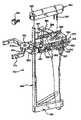
- FIG. 1is an exploded view of the resection apparatus of the present invention showing the positioning apparatus body, the angular adjustment component and the rotational alignment component.
- FIG. 2is a side plan view of the guide device of the resection apparatus of FIG. 1 attached to a distal human femur.
- FIG. 3is an exploded view of the pattern device of the resection apparatus of the present invention.
- FIG. 4is a side plan view of the resection apparatus shown in FIG. 2 with the pattern device fixed to the distal human femur.
- FIG. 5is an exploded front view of the cutting device of the resection apparatus of the present invention.
- FIG. 6is a top plan view of the pattern device and the cutting device of the resection apparatus of the present invention affixed to the distal human femur.
- FIG. 7is a side plan view of an intermedullary rod having a helical groove for use with the resection apparatus shown in FIG. 1 .
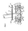
- FIG. 8is a partially exploded side plan view of an embodiment of the tibial resection apparatus of the present invention shown attached to the tibia, wherein the cutting guide clamps are of a fixed size and directly interconnect with the alignment rod.
- FIG. 9is a top plan view of the tibial resection apparatus, shown in FIG. 8 prior to insertion of the milling bit into the apparatus.
- FIG. 10is a partially exploded side plan view of another embodiment of the tibial resection apparatus shown in FIG. 8 , wherein the cutting guide clamps interconnect with the alignment rod by means of a cutting guide clamp linkage.
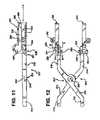
- FIG. 11is a side plan view of an embodiment of the cutting guide clamps shown in FIG. 8 , wherein the cutting guide clamps are adjustable.
- FIG. 12is a top plan view of the cutting guide clamps shown in FIG. 11 .
- FIG. 13is a perspective view of an embodiment of the tibial resection apparatus shown in FIG. 8 , showing the proximal tibial referencing stylus attached to the cutting guide clamps.
- FIG. 14is a cross-sectional view of the profile of the ends of the clamp members taken along line A-A in FIG. 12 .
- FIG. 15is a cross-sectional view of the profile of the ends of the cutting guides taken along line B-B in FIG. 12 , the ends of the clamps mating with the ends of the cutting guides for positioning the cutting guides with respect to the clamps.
- FIG. 16is a perspective view of an alternate embodiment of a U-shaped cutting guide for use in the present invention.
- FIG. 17is a top plan view of another alternate embodiment of a square U-shaped cutting guide for use in the present invention.
- FIG. 18is a perspective view of another alternate embodiment of a partial cutting guide for use in the present invention when the patellar tendon, patella, or quad tendon interferes with placement of the cutting guide about the tibia.
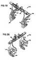
- FIG. 19is a rear perspective view of an embodiment of the pattern apparatus of the present invention.
- FIG. 20is a front perspective view of the pattern apparatus shown in FIG. 19 .
- FIG. 21is a partially exploded side plan view of the positioning apparatus shown in FIG. 19 .
- FIG. 22is an exploded perspective view of the cross-bar of the pattern apparatus shown in FIG. 19 .
- FIG. 23is a partially cut away side plan view of the pattern plate/cross-bar attachment linkage for interconnecting the pattern plate to the cross-bar as shown in FIG. 19 .
- FIG. 24is a perspective view of the positioning apparatus of the present invention.
- FIG. 25is a top plan view of the positioning apparatus shown in FIG. 24 .
- FIG. 26is an exploded perspective view of the positioning apparatus shown in FIG. 24 .
- FIG. 27is an exploded perspective view of the protractor rod guide assembly portion of the positioning apparatus shown in FIG. 24 .
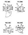
- FIGS. 28A-28Dare plan views of another embodiment of a rod guide assembly for use with the positioning apparatus shown in FIG. 24 .
- FIG. 29is a side plan view of an embodiment of the fixation device for affixing the pattern apparatus shown in FIG. 19 to a bone.
- FIG. 30is a partial side plan view of the pattern apparatus shown in FIG. 19 , showing the posterior/anterior referencing guide.
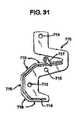
- FIG. 31is a side plan view of another embodiment of the pattern apparatus shown in FIG. 19 .
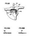
- FIG. 32is a side plan view of another embodiment of the positioning apparatus shown in FIG. 24 for use in performing ligament balancing;
- FIGS. 32A and 32Bare cross-sectional views along section A-A in FIG. 32 .
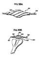
- FIGS. 33A and Bare front plan views of an embodiment of the cutting apparatus of the present invention for cutting a bone a in curvilinear cross-sectional plane.
- FIG. 34is a perspective view of a handle for guiding a milling bit along a cutting path.
- FIG. 35is a perspective view of another embodiment of the pattern apparatus shown in FIG. 19 , having a milling bit engaged therewith.
- FIG. 36is a side plan view of the pattern apparatus shown in FIG. 35 with the milling bit disengaged from the pattern apparatus.
- FIG. 37is another side plan view of the pattern apparatus shown in FIG. 36 showing the milling bit engaged with the pattern apparatus.
- FIG. 38is a perspective view of a femoral implant having a curved implant bearing surface.
- FIG. 39is a side plan view of the femoral implant shown in FIG. 38 .
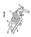
- FIG. 40is a side plan view of another embodiment of the pattern apparatus and positioning apparatus of the present invention for resecting a patella.
- FIG. 41is a top plan view of the patella resection apparatus shown in FIG. 40 .
- FIG. 42is a front plan view of the patella resection apparatus shown in FIG. 40 .
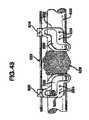
- FIG. 43is a perspective view of another embodiment of the pattern apparatus of the present invention for cutting a bone.
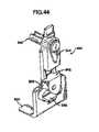
- FIG. 44is a perspective view of another embodiment of the alignment apparatus shown in FIG. 24 .
- FIG. 45is a partially exploded side plan view of another embodiment of the pattern apparatus of the present invention for cutting a bone.
- FIG. 46is a partially exploded perspective view of the interconnection of a handle with milling bit for use in connection with pattern plate shown in FIG. 45 .
- FIG. 47is front plan view of another cutting apparatus for use in connection with the present invention.
- FIG. 48is a side plan view of the femoral implant shown in FIG. 38 , FIGS. 48A , 48 B, 48 C and 48 D being sectional views taken along lines A-A, B-B, C-C and D-D of FIG. 48 , respectively.
- FIG. 49is a side plan view of the curvilinear milling bit and resection guide shown in FIG. 35 .
- FIG. 50is a side plan view of another embodiment of the femoral implant shown in FIG. 38 .
- the resecting apparatus of the present inventioncomprises a number of components, namely positioning apparatus generally indicated at 10 comprising positioning body generally indicated at 12 , angular adjustment block generally indicated at 32 , rotational alignment device generally indicated at 50 , pattern device generally indicated at 59 and cutting means generally indicated at 90 .
- the positioning apparatusincludes a positioning body generally indicated at 12 having sides 13 , top surface 14 , front surface 15 , back surface 19 and cross member 18 . Extending from a lower end of the positioning body 12 is positioning tongue 20 having an upper surface 22 . Extending into the positioning body 12 from top surface 14 to the cross member 18 and through the front and back surfaces 15 and 19 , is a gap generally defined by slots 16 and partial slot walls 17 . Sides 13 include apertures 24 for receiving locking screws 25 . Also extending through the body 12 from the back surface 19 to the front surface 15 are apertures 27 for receiving fixation screws 26 .
- the positioning apparatus 10receives and holds angular adjustment block generally indicated at 32 .
- Angular adjustment block 32includes a front surface 34 having wings 36 sized to be received by the slots 16 in the positioning body 12 to hold the angular adjustment block 32 .
- the angular adjustment block 32is locked into place in the positioning body 12 by means of locking screws 25 , which extend through apertures 24 in the positioning body 12 and contact the wings 36 of the angular adjustment block 32 to secure the angular adjustment block 32 to the positioning body 12 .
- the angular adjustment block 32establishes the angular alignment and anterior/posterior location of the positioning apparatus 10 .
- the angular adjustment block 32also includes back surface 38 and an aperture 40 extending from the back surface 38 through the angular adjustment block 32 to the front surface 34 .
- the aperture 40receives an intermedullary rod 42 therethrough.
- the intermedullary rod 42comprises a shaft 43 and a handle 44 .
- the shaft 43extends through the angular adjustment block 32 and into the intermedullary canal which extends along the axis of the femur to aid in establishing the orientation of the resection apparatus of the present invention as hereinafter described.
- the rotational alignment devicegenerally indicated at 50 , includes a shaft 51 having a groove 52 therealong and a block 53 having a back surface 54 and wings 56 .
- the rotational alignment device 50is interconnected with the positioning body 12 by means of the wings 56 received in slots 16 of the positioning body 12 .
- the rotational alignment device 50may be secured to the positioning body 12 by means of locking screws 25 which extend through apertures 24 in the positioning body 12 to contact the wings 56 .
- the locking screws 25may be made of various configurations depending upon their specific function. Importantly, the locking screws 25 are used to rigidly affix one component or device to another to ensure that the relative locations and orientations are maintained despite the rigors of surgery.
- the entire positioning apparatus 10is connected to a human femur 7 by means of the shaft 43 of the intermedullary rod 42 .
- the shaft 43extends through the angular adjustment block 32 , and thereby through the positioning body 12 into the intermedullary canal which extends along the axis of the femur 7 .
- the intermedullary rod 42shown in FIG. 7 , has a groove 41 transversing a helical path 45 along the axis of the shaft 43 .
- the groove 41relieves intermedullary pressure that leads to fatty embolisms.
- the basic concept of the intermedullary rod 42 with the groove 41is that as it is inserted into the femur, which contains liquid fatty tissue, the liquid fatty tissue is drawn up the groove 41 of the intermedullary rod 42 to draw the fatty liquid tissue out of the femur.
- the intermedullary rodwould have a hexagonal head, (not shown) to permit it to be driven by a powered device such as an electrical hand held tool.
- the groove 41does not have a cutting edge, which would risk perforation of the femoral cortex. Accordingly, the device does not cut solid material, but removes liquid material from the intermedullary canal. Therefore, the risk of fatty embolism is reduced.
- fixation screws 26may be advanced through the apertures 27 in the positioning body 12 until they make contact with the distal femoral condyles of the femur 7 , and are then driven into the distal femoral condyles of the femur 7 to initially affix the positioning apparatus to the distal femur 7 .
- the fixation screws 26may also be advanced and adjusted to make up for deficiencies in the distal femoral condyles. Accordingly, the positioning body 12 is positioned such that the front surface 15 is put into contact with the distal femoral condyles by direct contact, and the tongue 20 is positioned under the femur 7 and in contact therewith.
- the shaft 51 of the rotational alignment device 50extends above the femur 7 and allows for rotation of the pattern device 59 , hereinafter described, about the distal femur 7 . Additionally, the rotational alignment device 50 allows for the anterior/posterior positioning of the pattern device 59 with respect to the femur 7 .
- the configurations of the positioning body 12 , the angular adjustment block 32 and the rotational alignment device 50are not limited to the structure set forth herein, but may be of different shapes and may interconnect in different ways. These components may even be formed as a unitary or partially unitary device.
- the pattern device 59includes pattern plates 60 having tops 61 , and cutting paths, generally indicated at 62 , extending therethrough.
- the cutting paths 62outline the desired resection shape of the distal femur 7 .
- the cutting paths 62could include a first vertical path 64 , extending to a first diagonal path 65 , extending to a second diagonal path 66 , extending to a second vertical path 67 , extending to a third diagonal path 68 and then extending to a horizontal path 69 .
- the cutting paths 62could describe any desired resection shape for the femur 7 .
- the pattern plates 60also include locking screws 75 for interconnecting the pattern plates 60 with a crossbar 80 .
- the pattern device 59 of the present inventionpreferably includes two pattern plates 60 held in a spaced apart relationship by crossbar 80 .
- the crossbar 80separates the pattern plates 60 sufficiently to permit the pattern plates 60 to extend along the sides of the distal femur 7 .
- the crossbar 80includes a front surface 82 , back surface 84 , a top surface 83 , a central aperture 86 extending from the front surface 82 to the back surface 84 , a lock aperture 88 extending through the top surface 83 , and a lock screw 89 .
- the central aperture 86 of the crossbar 80receives the shaft 51 of the rotational alignment device 50 .
- the pattern device 59is interconnected with the positioning apparatus 10 so that the pattern device 59 is properly oriented with respect to the femur 7 .
- lock screw 89is extended through lock aperture 88 to contact the shaft 51 to lock the crossbar 80 and, accordingly, the pattern device 59 , onto the shaft 51 of the rotational alignment device 50 , and accordingly, to positioning apparatus 10 .
- This completed assemblyis attached to the femur 7 , as shown in FIG. 4 .
- the pattern plates 60include plate apertures 72 for receiving cannulated screws 70 which have apertures extending therethrough for receiving fixation nails 71 therethrough. Accordingly, after the pattern device 59 is interconnected with the positioning apparatus 10 , and properly located and oriented with respect to the femur 7 , the cannulated screws 70 are extended through the plate aperture 72 to contact the sides of the distal femur 7 . Then, in order to fix the pattern plates 60 with respect to the femur 7 , the fixation nails 71 are driven into the distal femur 7 to lock the pattern plate 60 into position on the distal femur 7 .
- the cannulated screws 70have sharp leading edges for allowing decisive purchase in the distal femur 7 before the introduction of the fixation nails 71 to complete fixation of the pattern device 59 to the distal femur 7 .
- the pattern plates 60by virtue of the cutting paths 62 , dictate the shape of the resection of the femur 7 .
- the cutting paths 62are essentially channels through the pattern plates 60 .
- the cutting paths 62receive the cutting device and guide it as it resects the surface of the distal femur 7 .
- the pattern plates 60straddle the distal femur 7 mediolaterally and are suspended by the crossbar 80 .
- crossbar 80maintains the proper relationship between the pattern plates 60 before and during the resection of the distal femur 7 .
- the location of the crossbar 80 and accordingly, the pattern plates 60may be adjusted with respect to the positioning apparatus 10 by adjusting the position of the block 53 of the rotational alignment device 50 within the slots 16 of the positioning body 12 , and locking the same with locking screws 25 .
- the cutting paths 62 in the pattern plates 60receive and guide the cutting device shown in FIG. 5 and generally indicated at 90 .
- the cutting device 90performs the actual cutting of the femur 7 to resect the femur 7 .
- the cutting devicemay be of any known configuration.
- the cutting deviceis a drill.
- the drill 90is generally cylindrical in shape and may possess helical cutting teeth along its length to cut the femur 7 .
- the drill 90includes a hexagonal end 95 to permit the use of an electric powered drive, typically an electric drill.
- the drill 90includes drill bushings 92 at the ends of the drill 90 to provide a non-metallic bearing between the cutting paths 62 in the pattern plates 60 to avoid galling and to ensure smooth articulation of the drill 90 along the cutting path 62 .
- retention springs 94Positioned between the drill bushings 92 and the drill 90 are retention springs 94 which are essentially coil springs retained within the drill bushings 92 to allow the drill bushings 92 to be easily attached and removed from the drill 90 .
- These retention springs 94are commercially available in medical grade stainless steels.
- the drill bushings 92retain the retention springs 94 which hold the drill bushings 92 in position 92 on the drill 90 while allowing the drill bushings 92 to rotate freely.
- the drill 90may also include circumferential grooves 91 for allowing attachment and retention of the drill bushings 92 by means of the retention springs 94 .
- the configuration of the drill 90can vary in accordance with what is known in the art, as long as the cutting device can follow the cutting paths 62 in the pattern plates 60 to resect the femur 7 .
- positioning apparatus 10may be removed from connection to the distal femur 7 leaving the pattern device 59 attached to the distal femur 7 to permit resecting of the distal femur.
- the drill 90is then positioned within the cutting paths 62 between the pattern plates 60 .
- the drill 90is rotated by power means in connection with the hexagonal end 95 , and is then moved along the cutting path 62 to resect the distal femur 7 .
- the cutting meanscould be operated by hand.
- the pattern plates 60may also comprise plates having edges in the shape of the desired distal femoral resection pattern.
- the cutting devicemay be drawn along the edges of the pattern plates to resect the distal femur.
- any cutting device that can be employed to follow the cutting paths in the pattern platesis considered to be within the scope of this invention.
- the resection apparatus of the present inventionprovides extremely accurate and reproducible bone cuts. While the anterior and distal areas of the femur will almost always be able to be prepared in this manner, interference from soft tissue such as fat and ligaments may prohibit satisfactory preparation of the posterior femur. The preparation of any remaining femoral surfaces may be completed in any manner known in the art after using the instrumentation of the present invention.
- the tibial resection apparatus of the present inventionincludes a number of components, namely, cutting guide clamps generally indicated at 210 , cutting guides generally indicated at 220 , ankle clamp generally indicated at 250 , alignment rod generally indicated at 260 , cutting guide clamp linkage generally indicated at 270 , fixation block generally indicated at 280 , proximal tibial referencing stylus generally indicated at 290 , and milling bit generally indicated at 255 .
- the cutting guides 220may be formed integrally with the cutting guide clamps 210 as shown in FIGS. 8 and 9 , or as separate members as shown in FIGS. 11 , 12 and 13 .
- the cutting guides 220may ride the alignment 260 as shown in FIGS. 8 and 9 , or they may interconnect with the alignment rod 260 by means of cutting guide clamp linkage 270 , as shown in FIGS. 11 , 12 and 13 .
- the ankle clamp 250is attached at or just above the ankle and exterior to the skin. Any conventional ankle clamp may be used to firmly engage the ankle, or to engage the tibia above the ankle, to obtain a reference point for the other components of the present invention.
- the ankle clampis interconnected with and locked into place on the alignment rod 260 in any way known in the art.
- the alignment rod 260is vertically adjustable with respect to the ankle clamp 250 . This vertical adjustment can be achieved at the ankle clamp 250 , at the interconnection of the ankle clamp 250 and the alignment rod 260 , or within the alignment rod 260 itself.
- the alignment rodincludes a first lower end 262 having an aperture 263 extending vertically therein for telescopically receiving a second upper end 265 of the alignment rod 260 .
- a set screw 264is provided for fixing the upper end 265 with respect to the lower end 262 .
- the fixation block 280is interconnected with an upper end of the alignment rod 260 by means of an aperture 282 in the fixation block 280 sized to receive the alignment rod 260 therethrough, or in any other manner known in the art.
- a set screw 284may be provided to extend into the fixation block 280 , through set screw aperture 286 in fixation block 280 , to contact the alignment rod 260 , to lock the fixation block 280 onto the alignment rod 260 .
- the fixation block 280additionally includes apertures extending vertically therethrough for receiving fixation pins 288 for affixing the fixation block 280 to the proximal tibia 208 .
- the ankle clamp 250is attached about the ankle, or about the tibia just above the ankle, on the exterior of the skin.
- the fixation block 280is already interconnected with the alignment rod 260 . It is preliminarily positioned over the proximal tibia 208 , and one of the fixation pins 288 is driven into the proximal tibia 208 . Thereafter, the alignment rod 260 is adjusted to establish proper varus/valgus alignment and flexion/extension angulation as is conventionally known.
- the other fixation pin 288is driven into the proximal tibia 208 to completely fix the fixation block 280 to the proximal tibia 208 to lock in the proper alignment of the alignment rod 260 . Then, the fixation block 280 may be locked into position on the alignment rod 260 .
- the cutting guide clamps 210 and the cutting guides 220may be employed.
- the cutting guide clamps 210are interconnected with the alignment rod 260 by means of cutting guide linkage 270 .
- the cutting guide clamps 210could directly interconnect with the alignment rod 260 through apertures in the cutting guide clamps 210 , as shown in FIGS. 8 and 9 . As shown in FIG.
- the cutting guide clamp linkage 270comprises a body 271 having an alignment rod aperture 272 for receiving and riding the alignment rod 260 and a pivot locking set screw 274 which extends into the cutting guide clamp linkage 270 through set screw aperture 275 for contacting the alignment rod 260 and locking the cutting guide clamp linkage 270 with respect to the alignment rod 260 .
- the alignment rod 260may be desirable for the alignment rod 260 to have a flattened surface extending longitudinally along the alignment rod 260 for co-acting with set screw 274 for maintaining proper alignment between the cutting guide clamp linkage 270 and the alignment rod 260 .
- the cutting guide clamp linkage 270also includes a pivot shaft 276 rigidly interconnected with the body 271 of the cutting guide clamp linkage 270 by member 277 to position the pivot shaft 276 a distance away from the body 271 such that the cutting guide clamps 210 can be interconnected with the pivot shaft 276 and can be properly utilized without interfering with the body 271 of the cutting guide clamp linkage 270 .
- the cutting guide clamp linkage 270is moved into its approximate desired position at the proximal tibia 208 . It should be noted that the cutting guide clamp linkage 270 of present invention is positioned on the alignment rod 260 at the beginning of the procedure, prior to aligning the alignment rod 260 , and prior to interconnecting the fixation block 280 with the alignment rod 260 . However, it is within the scope of the present invention to provide a cutting guide clamp linkage 270 which is attachable to the alignment rod 260 after the alignment rod 260 has been aligned and locked into position.
- the cutting guide clamp linkage 270After the cutting guide clamp linkage 270 is preliminarily approximately located, it is locked into place on the alignment rod 260 . Thereafter, the cutting guide clamps 210 may be interconnected with the pivot shaft 276 by means of corresponding pivot apertures 217 in the cutting guide clamps 210 .
- the cutting guide clamps 210include opposing hand grips 212 for grasping and manipulating the cutting guide clamps 210 .
- Crossbar members 214extend from the hand grips 212 to clamp members 218 .
- the crossbar members 214cross over each other at cross over point 215 whereat the crossbar members 214 have mating recessed portions 216 which function to maintain the hand grips 212 in the same plane as the clamp members 218 .
- the crossbar members 214can pivot with respect to each other such that movement of the hand grips 212 towards each other moves the clamp members 218 together, and likewise, movement of the hand grip members 212 away from each other serves to move the clamp members 218 apart in the same manner as scissors or pliers.
- the crossbar members 214have corresponding pivot apertures 217 for receiving the pivot shaft 276 of the cutting guide clamp linkage 270 .
- the cutting guide clamps 210pivot about the pivot shaft 276 of the cutting guide clamp linkage 270 .
- the crossbar members 214could be interconnected with each other by a rivet or other means known in the art, or could be entirely independent pieces which co-act as set forth above only upon being seated on pivot shaft 276 .
- the clamp members 218 of the cutting guide clamps 210include cutting guide adjustment screw apertures 219 at the far ends thereof for receiving A-P adjustment screws 230 for adjustably interconnecting the cutting guides 220 with the clamp members 218 , for adjustable movement in the direction shown by arrow C in FIG. 11 .
- the clamp members 218may be adjustably interconnected with the cutting guides 220 in any way known in the art.
- the cutting guide adjustment screw apertures 218are threaded and the cutting guides 220 have corresponding elongated apertures 228 extending over a portion of the length thereof for receiving the A-P adjustment screws at a desired location therealong.
- the A-P adjustment screwsinclude a head 231 , a retaining head 232 , and a threaded shaft 234 .
- the A-P adjustment screws 230are tightened down to lock the cutting guides 220 onto the clamp members 218 by actuating the head 231 to turn down the threaded shaft 234 with respect to the clamp member 218 .
- the retaining head 232 of the A-P adjustment screwsprevent the shaft 234 from being backed off out of engagement with the clamp member 218 .
- the clamp members 218are shaped with opposing interior edges having chamfers 238 and the opposite exterior edges of the cutting guides 220 have mating recesses 239 , both of said profiles extending along the contacting surfaces of the clamp members 218 , as seen along line A-A in FIG. 12 , and the cutting guides 220 , as seen along line B-B in FIG. 12 , to maintain a proper planar alignment therebetween.
- the cutting guides 220may include A-P adjustment screw recesses 237 for receiving the head 231 of the A-P adjustment screw 230 .
- the cutting guides 220further include tibia attachment means for attaching the cutting guides 220 to the tibia 208 .
- Any known attachment meansmay be employed to attach the cutting guides 220 to the tibia 208 .
- a preferred attachment means for attaching the cutting guides 220 to the tibia 208are pins 236 extending through pin apertures 227 in the cutting guides 220 .
- the pins 236may be captured in the pin apertures 227 , or they may be entirely separate.
- Such meansmay include a plurality of small pins captured by the cutting guide 220 , or any other suitable means. After the preliminary attachment of the cutting guides 220 to the tibia 208 , final attachment may be made by attachment pins 236 or by any other means known in the art.
- the cutting guides 220include cutting slots 222 which each comprise lower cutting slot guide surface 223 and upper cutting slot retaining surface 225 , as well as cutting slot entrance and exit 224 at one end thereof and cutting slot end wall 226 at the other end thereof.
- the cutting slot 222is of a length sufficient to extend across the proximal tibia 208 , at a desired angle to the intermedullary canal, at the widest point of the proximal tibia 208 , to allow the entire upper surface of the proximal tibia 208 to be cut.
- the cutting slot 222is of a size sufficient to receive a cylindrical milling bit 255 such as that shown in FIG. 16 and described in U.S. Pat. No.
- the milling bit 255comprises central cutting portion 257 having helical cutting teeth along its length for cutting bone.
- the milling bit 255further comprises spindles 256 extending from the central cutting portion 257 for supporting the central cutting portion 257 .
- the milling bit 255is inserted into and received in the cutting slot 222 through cutting slot entrance 224 , along the direction shown by arrow A in FIG. 16 .
- the cutting slot entrance 224may be of a wider slot area or an upturned portion of the slot 222 or the milling bit 255 may merely be inserted and removed from the slot 222 at an end thereof.
- the spindles 256extend through and co-act with the lower cutting guide surface 223 and the upper retaining surface 225 of the cutting slot 222 to guide the milling bit 255 along the cutting slot 222 to resect the proximal tibia 208 , along the direction shown by arrow B in FIG. 16 .
- a means for engaging the milling bit 255 with a drive means such as an electric drill, or other drive meansis a means for engaging the milling bit 255 with a drive means such as an electric drill, or other drive means.
- This engagement meansmay include a hexagonal head on one of the spindles, or any other suitable method of engagement known in the art.
- bushingsmay be employed, either on the milling bit 255 or captured by the cutting slot 222 , to provide a non-metallic bearing between the spindles 256 of the milling bit 255 and the cutting slot 222 to avoid galling and to ensure smooth articulation of the milling bit 255 along the cutting slots 222 .
- the configuration of the milling bit 255may be varied in accordance with what is known in the art, as long as the cutting device can follow the cutting path of the cutting slot to resect the proximal tibia.
- other cutting toolsmay be used in accordance with the present invention, including an oscillating or reciprocating saw or other means for resecting the tibia by following the cutting slots on the cutting guides.
- the cutting guides 220are adjusted with respect to the clamp members 218 for proper anterior-posterior positioning to extend along the proximal tibia 208 for guiding the milling bit 255 .
- the cutting slots 222should extend beyond the edges of the proximal tibia 208 .
- a proximal tibial referencing stylus 290may be attached to a referencing bracket 292 on the cutting guides 220 .
- the referencing bracket 292may be positioned in any location on the cutting guides 220 , or on any other convenient component of the tibia resection system of the present invention.
- the referencing stylus 290may be formed as part of a component of the present invention, or as a separate component which could function merely by contacting the cutting guides 220 of the present invention or any other component thereof.
- the referencing stylus 290shown in FIG.
- stylus body 294which may be interconnected with the referencing bracket 292 in any manner known in the art, preferably by a quick release and connect mechanism or a threaded connection.
- the stylus body 294supports a stylus arm 296 , which is rotatable with respect to the stylus body 294 and configured to extend out and down from the stylus body 294 to contact the proximal tibia 208 at a tip 298 of the stylus arm 296 .
- the stylus body 294 , arm 296 and tip 298are sized to contact the proximal tibia 208 to reference the positioning of the cutting guides 220 to cut the proximal tibia at a proper distance below the proximal tibia 208 as is known in the art.
- the stylus arm 296may include more than one tip 298 , such other tips extending down from the stylus body 294 in varying distances.
- the hand grips 212are actuated to press the cutting guides 220 against the proximal tibia 208 to preliminarily lock them into position on the proximal tibia 208 .
- the cutting guides 220are fixed to the proximal tibia 208 by pins 236 or any other desired fixation means.
- the fixation block 280can then be removed from the proximal tibia 208 , and the proximal tibia 208 may be resected.
- the cutting operationis similar to the cutting operation set forth in U.S. Pat. No. 5,514,139, filed Sep. 2, 1994 by Goldstein, et al.
- the cutting operationcomprises inserting the milling bit 255 into the cutting guide slots 222 through the slot entrance/exit 224 to position the central cutting portion 257 between the cutting guides 220 , the spindles 256 extending through the cutting guide slots 222 .
- the drive meansmay be interconnected therewith, actuated, and the milling bit 255 moved along the cutting slots 222 to resect the proximal tibia 208 .
- a handlemay be provided for attachment to the spindle which is not driven so that such spindle may be guided evenly through the cutting slots 222 to facilitate the cutting procedure.
- a handlecan be provided which interconnects with both spindles to further facilitate control of the milling bit 255 during the cutting procedure.
- the bushings that fit over the spindles 256 of milling bit 255 and ride in the cutting slots 222may be captured in the ends of the handle and the milling bit received therethrough.
- the cutting guide 320 shown in FIG. 16is of a generally U-shaped configuration, having cutting guide slots 322 , lower cutting guide surface 323 , upper retaining surface 325 , pin apertures 327 and alignment rod aperture 328 .
- This cutting guide 320is used in the same manner as the cutting guides hereinbefore described, the differences being that the cutting guide 320 interconnects directly with the alignment rod and that various size cutting guides must be provided to accommodate various sized tibias.
- the cutting guide 320shown in FIG. 17 , operates in the same manner as the cutting guide devices hereinbefore described, but it does not include cutting guide clamps.
- the cutting guide 320includes cutting slots 322 , and it interconnects directly with alignment rod by means of aperture 328 .
- the distance between facing members 330can be adjusted by moving base members 332 and 334 with respect to each other to size the cutting guide 320 for the tibia to be cut.
- the base members 332 and 334may be locked with respect to each other by set screw 336 or any other means known in the art.
- FIG. 18shows an embodiment of the cutting guide for use when the patellar tendon, the patella, or the quad tendon interferes with the placement of the other cutting guides of the present invention.
- the cutting guide 350may be directly interconnected with the alignment rod, and positioned on the tibia as hereinbefore set forth.
- this embodiment of the inventionincludes only one cutting guide.
- the cutting guide 350 and the cutting guide slot 322may be wider than in the previous embodiments to help stabilize the milling bit in operation.
- the milling bitmay be first plunged across the tibia, and then moved therealong.
- the milling bitmay be spring loaded to increase resistance as it is plunged through the cutting guide to bias the bit against being plunged too far across the tibia to cause damage to the tissue about the tibia.
- a support membernot shown, could be provided to extend from the cutting guide 350 , over and across the tibia to the other side thereof where it could have a slot to capture the milling bit and provide additional support thereto.
- the reference numerals 338 , 360 and 392correspond to the reference numerals 238 , 260 and 292 respectively.
- the pattern apparatus of the present inventioncomprises pattern plates, generally indicated at 432 , and crossbar apparatus, generally indicated at 440 .
- Pattern plates 432include fixation apertures 434 extending therethrough for accepting fixation means, as will hereinafter be described, for affixing the pattern plates 432 to a bone.
- the pattern plates 432further include a cutting path 436 for dictating the path along which a bone is to be cut. As shown in FIGS. 19-23 , which are directed to an embodiment of the present invention for resecting a distal femur, the cutting path 436 in the pattern plates 432 matches the profile of a femoral component of a knee prosthesis for resecting the femur to accept the femoral component of the prosthesis.
- the cutting path 436could be identical in size and shape to an interior bearing surface of a femoral component of the knee prosthesis, or could vary in size and shape in accordance with alternative methods and apparatus used to perform the resection.
- the cutting pathcould be larger than the desired resection, but a larger cutting tool could be used to arrive at a resection of the desired the desired size.
- the cutting path 436includes an anterior end 436 A, an anterior cut portion 436 B, an anterior chamfer portion 436 C, a distal cut portion 436 D, a posterior chamfer portion 436 E, a posterior cut portion 436 F, and a posterior end 436 G.
- the cutting path 436could be of any desired shape in accordance with the prosthesis systems of the various manufacturers of such prosthesis, the desires of the surgeon utilizing the apparatus and/or the application for which a bone is to be cut.
- a single pattern plate 432may be employed in resecting a femur or other bone (and in some cases, i.e., a partial femur resection, it may be preferable to employ a single pattern plate 432 ), two pattern plates 432 are generally employed to co-act with each other to support a cutting means on two sides of a bone to be cut.
- a preferred embodiment of the present inventionas shown in FIGS. 19-21 , comprises two pattern plates 432 positioned on opposing sides of a femur.
- the pattern plates 432are interconnected with each other, and maintained in proper alignment with respect to each other by a crossbar apparatus generally indicated at 440 , to straddle a bone.
- the pattern plates 432include crossbar apertures 438 for interconnecting with the crossbar apparatus 440 .
- the pattern platesmay also include crossbar slots 439 for permitting quick connect/disconnect between the pattern plates 432 and the crossbar apparatus 440 .
- the pattern plates 432could interconnect with the crossbar in any other manner known in the art, or especially with bone cutting applications other than resecting the femur, the pattern plates 432 could be used without a crossbar.
- the crossbar apparatus 440includes a number of component parts, namely, T-bar 442 having a top 444 and a stem 446 interconnected with and extending from the top 444 in the same plane.
- the T-bar 442shown in the figures, comprises a flat metal member having a uniform rectangular cross-section through both the top 444 and the stem 446 .
- Three threaded lock apertures 448are formed through the T-bar 442 , one at each end of the top 444 and at the far end of the stem 446 .
- Lock screws 450having gripable heads 452 and shafts 454 with threaded waists 456 , threadably engage the threaded lock apertures 448 in the T-bar 442 .
- the lock screws 450further include pin holes 458 extending radially through the shafts 454 at the terminal ends thereof for receiving pins 459 for capturing the lock screws 450 on the T-bar 442 .
- the crossbar apparatus 440further includes linkages 460 having a first end for interconnection with the T-bar 442 and a second end for supporting and engaging pattern plates 432 .
- the first ends of the linkage 460include a lower flat surface 462 for contacting the T-bar 442 , overhanging shoulders 464 for contacting the sides of the T-bar 442 , and an upper flat surface 466 for contact with the lock screws 450 for locking the linkages 460 onto the T-bar 442 .
- the second ends of the linkage 460include cylindrical supports 468 for supporting the pattern plates 432 thereon.
- the cylindrical supports 468include axial extending apertures 469 for receiving capture pins 470 therethrough, the capture pins 470 including flanged ends 472 and threaded ends 474 .
- the capture pins 470serve to capture pattern lock nuts 476 on the linkages 460 , the capture pins 470 extending through the axial apertures 469 , the flanged ends 472 retaining the capture pins 470 therein, the threaded ends 474 extending out of the cylindrical supports 469 and into the threaded interior 477 of the pattern lock nuts 476 .
- the cylindrical supports 468receive the crossbar apertures 438 of the pattern plates 432 and the pattern lock nuts 476 are threaded down onto the capture pins 470 to secure the pattern plates 432 to the crossbar apparatus 440 .
- the crossbar apparatussufficient for supporting the pattern plates of the present invention are considered within the scope of the present invention.
- the positioning apparatusgenerally comprises positioning body 520 and alignment apparatus 580 .
- the positioning body 520comprises a frame 522 having sides 524 , bottom 526 and top 528 arranged to form a frame having a rectangular aperture defined therewithin.
- the top 528further includes a head 530 formed thereon having a linkage aperture 532 extending therethrough at an upper end thereof, and having a lock aperture 534 extending from the upper edge of the head to the linkage aperture 532 .
- a lock screw 536having a threaded shaft 538 extends into and is threadably engaged with the lock aperture 534 for locking the head 530 to a linkage, namely crossbar linkage 540 .
- Crossbar linkage 540includes a first end having an upper flat surface 542 for interconnecting with the crossbar in a manner similar to the pattern plate linkages for attaching the pattern plates to the crossbar as hereinbefore described.
- the crossbar linkage 540further includes a shaft 544 which is received by the linkage aperture 532 in the head 530 to interconnect the positioning body 520 with the crossbar linkage 540 and hence with the crossbar apparatus 440 and the pattern apparatus 430 .
- the positioning bodycan then be locked onto the crossbar linkage 540 by means of lock screw 536 .
- the end of shaft 544 of the crossbar linkage 540includes projections 546 extending axially from the shaft 544 .
- the projections 546extend beyond the frame 522 and are received in slots 556 in alignment indicator 550 for keying the orientation of the alignment indicator 550 with the alignment of the crossbar linkage 540 , and hence with the alignment of the crossbar apparatus 440 and the pattern apparatus 430 .
- the alignment indicator 550includes an alignment arrow 552 for indicating alignment on a scale that may be set forth on the positioning body 520 .
- An indicator pin 558 having a shaft 559may be employed to pin the alignment indicator 550 to the crossbar linkage 540 .
- the skid 560includes skid apertures 562 , one of which may include an aperture flat 564 for ensuring proper alignment and positioning of the skid 560 with respect to the positioning body 520 .
- the skid 560is attached to the bottom 526 of the positioning body 520 by means of skid bolts 566 having threaded shafts 568 which co-act with threaded apertures in the bottom 526 of the positioning body 520 .
- the skidscould be formed integrally as part of the positioning body.
- the sides 524 of the positioning body 520include slots 570 extending in a facing relationship along the sides 524 .
- the slotsextend from exterior surfaces of the sides to interior surfaces thereof, i.e., to the interior rectangular aperture formed within the positioning body 520 .
- the alignment apparatus 580interconnects with the positioning body 520 by means of alignment guide body 582 which is a U-shaped member having sides 584 and a bottom 586 .
- the alignment guide body 582is sized to fit within the rectangular aperture formed within the positioning body 520 .
- the alignment guide body 582is retained within the positioning body by means of guide studs 572 that extend through the sides 524 of the positioning body 520 within the slots 570 and into guide apertures 588 at one side of the alignment guide body 582 .
- a lock stud 584extends through the slot 570 in the side 524 of the positioning body 520 and into a threaded lock aperture 589 in the alignment guide body 582 .
- the guide studs 572 and the lock stud 574co-act to maintain the alignment guide body 582 within the positioning body 520 , and the lock stud 574 can be threaded down to lock the vertical position of the alignment guide body 582 with respect to the positioning body 520 .
- the alignment plate 592includes bolt apertures 595 aligned with the plate apertures 591 of the alignment guide body 582 , and plate bolts 594 extend through the bolt apertures 595 in the alignment plate 592 and into the plate apertures 591 to secure the alignment plate 592 to the alignment guide body 582 .
- the alignment plate 592further includes rod guide aperture 597 which receives rod guide bolt 596 therethrough to interconnect the alignment plate 592 with the IM rod guide 610 as will hereinafter be described. Additionally, the alignment plate 592 includes lock slot 606 extending through the alignment plate 592 along an arc for purposes hereinafter described.
- the IM rod guide 610includes IM rod aperture 612 for receiving an IM rod therethrough.
- the IM rod guide 610is interconnected at a forward end with the alignment plate 592 by means of plate attachment aperture 614 on the rod guide 610 which receives rod guide bolt 596 therein, after such bolt 596 passes through the alignment plate 592 to secure the rod guide 610 in a pivoting relationship with respect the alignment plate 592 at forward ends of the rod guide 610 and the alignment plate 592 .
- the IM rod guide 610is additionally interconnected with the alignment plate 592 by rod guide lock bolt 600 which includes a threaded shaft 210 and pin aperture 602 .
- the rod guide lock bolt 600extends through the slot 606 in the alignment plate 592 and through threaded lock bolt aperture 616 in the rod guide 610 where it is captured by means of capture pin 618 extending through the pin aperture 602 .
- the IM rod guidefurther includes rod guide handle 620 which is configured to be easily manipulated.
- the alignment plate 592further includes a printed angular rotation scale which indicates the degree of angular rotation between the rod guide 620 and the alignment apparatus, and hence, the angular rotation between the IM rod and the positioning body 520 .
- a printed angular rotation scalewhich indicates the degree of angular rotation between the rod guide 620 and the alignment apparatus, and hence, the angular rotation between the IM rod and the positioning body 520 .
- IM rod guide block 630is used instead of the alignment plate 592 and the alignment guide body 582 .
- the IM rod guide block 630includes a rear surface 632 , a front surface 634 , a top surface 636 and sides 638 .
- the sides 638include retaining flanges 640 at the rear and front surfaces for retaining the IM rod guide block 630 within the rectangular aperture formed by the positioning body 520 .
- the IM rod guide block 630further includes IM rod aperture 642 extending through the block 630 from the rear surface 632 to the front surface 634 for accepting the IM rod therethrough.
- the rod aperture 642extends through the guide block 630 at an angle A with respect to axis of the guide block for accommodating the varus/valgus orientation of the femur.
- the guide block 630is part of a set of blocks having rod apertures of various angles extending therethrough, i.e., 5, 7, 9, 11, 13 degrees, for use with femurs having varying angles of orientation.
- the guide block 630also includes lock aperture 646 for locking the proper vertical position of the guide block 630 with respect to the positioning body 620 .
- the guide block 630may additionally include two apertures 644 for accepting an anterior referencing arm for use in determining the anterior/posterior size of the femur. It should be noted that other alignment means for aligning the positioning apparatus with respect to a bone to be cut are considered within the scope of the present invention.
- FIG. 29shows a preferred fixation means, generally indicated at 660 .
- the fixation means 660includes a spike plate 664 carrying on one side thereof a spike or spikes 662 for contacting, and even extending into, bone 661 .
- spike plate socket 666At the other side of the spike plate 664 is spike plate socket 666 for receiving plate driving ball 668 in a keyed relationship therewith.
- the driving ball 668is interconnected to an end of driving sleeve 670 and which has a threaded aperture extending therein from the opposite end thereof.
- a driving screw 672 having a threaded shaft 674co-acts with the internally threaded driving sleeve 670 such that the rotation of the driving screw 672 either propels or retracts the driving sleeve 670 , as well as the spike or spikes 662 , with respect to the driving screw 672 .
- the driving screw 672further includes a captured head 678 and capture flange 676 .
- the captured head 678is received within a fixation aperture 434 in the pattern plate 432 , the capture flange 676 preventing the captured head 678 from passing through the fixation aperture 434 .
- a driving cap 680is interconnected with the captured head 678 at the outside of the pattern plate 432 .
- the driving cap 680includes a shaft 682 received by the captured head 678 , a flanged head 684 for contacting against the outside of the pattern plate 432 , and a driver recess 686 of any desirable configuration for receiving driving means such as a flat, phillips or hex head driving means for driving the driving cap 680 to drive the driving screw 672 to move the spike or spikes 662 towards or away from a bone.
- driving meanssuch as a flat, phillips or hex head driving means for driving the driving cap 680 to drive the driving screw 672 to move the spike or spikes 662 towards or away from a bone.
- this type of fixation meansallows for fixation of the pattern plates 432 to even osteoporotic bones. Additionally, this fixation means is self-adjusting to fit changing contours of bones. Further, because of its relatively low profile, this fixation means does not interfere with soft tissue about a bone to be cut.
- Other types of fixation meansinclude cannulated screws, pins, spring loaded screws, captured screws, spiked screws and/or combinations thereof, all of which are considered within the scope of the present invention and could be used in connection with the present invention.
- the apparatus of the present inventionfurther includes built-in anterior/posterior referencing means as shown in FIG. 30 for use in connection with preparation of the distal femur in total knee replacement.
- anterior/posterior referencingrefers to proper positioning of the distal femur cuts with respect to the anterior and/or posterior sides of the femur or other bone to be cut.
- the anterior/posterior difference between femoral implant sizesmay vary by as much as 3 to 5 millimeters between sizes. Of course, many femurs are between sizes. Disregarding proper positioning of the cutting guide and the associated femur cuts could lead to flexion contracture (where the bone is slightly below size and the implant adds too much material to posterior side of femur which results in the inability to move the knee into flexion because the extra posterior material contacts the tibial implant components) and/or anterior notching of the femur (where the bone is slightly above size and the anterior runout point of the anterior cut is recessed in the anterior side of the bone in a sharp notch, thus seriously weakening the structural integrity of the distal femur, especially under cyclic fatigue or impact loading conditions).
- anterior referencing systemshave a major advantage over posterior referencing systems in that they theoretically never notch the anterior cortex of the femur.
- the drawback of anterior referencingis that a slightly larger bone results in collateral ligament laxity in flexion and a slightly smaller bone will result in collateral ligament tightening in flexion (flexion contracture).
- Posterior referencing systemshave a major advantage over anterior referencing systems in that they theoretically never develop flexion contracture.
- the drawbackis that a slightly large femur is prone to anterior notching, which can increase the likelihood of distal femoral fractures under either impact loading or cyclic fatigue loading.
- the positioning apparatus 510references the posterior femoral condyles (posterior referencing), while the pattern plates 432 allow for precise referencing of the anterior femoral cortex.
- the anterior referencing devicecan be as simple as that shown in FIG. 30 , wherein a referencing pin 694 is placed through the anterior-most cutting paths 436 of the pattern plates 432 to contact the anterior femoral cortex 661 .
- the pattern plates 432include markings S (smaller size) and L (larger size). When the pin 694 falls between the S and L marks, the pattern plates 432 are the proper size and are properly positioned for that femur.
- the pattern plate 432could be adjusted vertically via means not shown to compensate for between-size bones.
- the pattern platecould include a plunger assembly at the anterior end of the cutting path.
- the plungercould be movable vertically to contact the femur and indicate size of the femur with respect to the pattern plate in use.
- the plungercould be incrementally marked from +4 to ⁇ 4 millimeters with 0 being the proper size for the pattern plates in use.
- the pattern platescould be sized up or down if the femur is off of the scale, or the pattern plates could be moved up or down to compensate for between size bones depending upon surgeon preference. If, for example, a bone registers a +2, anterior notching of the femur would occur. To avoid this, the pattern plates could be moved anteriorally 1 millimeter to +1.
- anterior notchingwould be minimized and the posterior femoral condyles would only lack 1 millimeter of material, which should not be detrimental as some ligamentous laxity in flexion is acceptable because the collateral ligaments are normally slightly looser in flexion than they are in extension. It should be noted that the radii or curve in the anterior-most area of the cutting path will assure that anterior notching is easily avoidable.
- the pattern platesbasically comprise only the lower edge, or bearing surface 716 of the cutting path 436 of pattern plates 432 shown in FIGS. 19-21 .
- the pattern plate 710includes fixation apertures 712 and crossbar aperture 714 .
- the milling apparatusbears against the bearing surface and follows the same therealong to resect the bone in accordance with the shape of the bearing surface 716 .
- the bearing surfacecould be smaller or larger than the desired cut location depending on the size of the milling apparatus.
- the pattern plate 710could further include a groove or guide means 718 extending in the pattern plate alongside the bearing surface and the milling apparatus could include an arm or other retaining linkage 717 extending from the handle or bushing of the milling apparatus and into the groove 718 for engagement with the groove 718 for guiding or retaining the milling apparatus along the bearing surface 716 of the pattern plate 710 .
- the bearing surfacecould also comprise just the upper surface of the cutting path 436 of the pattern plates 432 , as shown in FIGS. 19-21 .
- an alternative embodiment of the alignment guide body 730can be used for performing ligament balancing.
- the alignment guide body 730 of this embodimentcan include a skid 732 formed as a part of the guide body 730 , or attachable thereto.
- the skid 732is of a relatively thick cross-section, approaching or equal to the cross-section of the guide body 730 .
- the guide body 730is attached to the femur 661 and the femur may be moved from extension to flexion and back, while the ligament tension of the collateral ligaments is reviewed. Ligamentous release can be performed to balance the ligaments.
- shims 736in either a rectangular cross-section ( FIG. 32A ) or an angled cross-section ( FIG. 32B ), can be used in connection with the alignment guide body 830 and skid 732 . These shims could be positioned between the underside of the skid 732 and the resected tibia.
- a cylindrical milling bitis used for following the cutting path described in the pattern plates for resecting a bone.
- a flat reciprocating bitmuch like a hacksaw, for following the cutting paths described in the pattern plates for resecting a bone.
- a cylindrical milling bit or a flat reciprocating bit having a smooth center section without cutting meansAn advantage of a cutting tool without cutting means along a center portion thereof is the protection of posterior cruciate ligament during resection of the femur. Accordingly, one cutting tool could be used to make the anterior cut, the anterior chamfer, the distal cut and the posterior chamfer, while another cutting tool, with a smooth center portion, could be used to make the posterior cut to avoid any chance of jeopardizing the posterior cruciate ligament.
- milling bits herein describedcan be used with or without a guide handle as will hereinafter be described. Further, it should be pointed out that it is within the scope of the present invention to fabricate the milling bit or other cutting tool from metal as heretofore known, or to alternatively fabricate the milling bit or other cutting tool from a ceramic material.
- An advantage of a ceramic milling bit or cutting toolis that such resists wear and, accordingly would be a non-disposable component of the present invention which would help to reduce the cost of the system of the present invention.
- the term cutting profilethe profile geometry of a mediolateral section taken normal to the cutting path through the bony surfaces created by cutting the bone.
- a milling apparatus having a three-dimensional profile, or a form cuttercan be used to shape a bone in three-dimensions.
- the curved profile milling bit 750like the milling bits used in the previous embodiments of the present invention, includes cutting teeth 752 along the length thereof and spindles 754 at the ends thereof. This milling bit 730 can follow a pattern described by pattern plates and can be guided with a handle as will be hereinafter described.
- any prosthetic implant used for attachment to a femur resected by the curved profile milling bitwould necessarily have an appropriately contoured inner fixation surface for mating with contoured surface of the femur.
- the curved profile milling bitcould have one or more curvilinear bulges along the length thereof, as shown in FIG. 33 , or alternatively, could have one or more bulges discretely formed along the length thereof as shown in FIG. 35 .
- a guide handlegenerally indicated at 698 may be used to guide the milling bit along the cutting path of the pattern plate.
- the guide handle 698comprises a grip portion 700 which is grasped by the user for manipulating the guide handle 698 and accordingly, the milling bit.
- the grip portion 700is interconnected with a crossbar member 702 which includes a extension member 703 telescopically interconnected therewith.
- the crossbar member 702 and the extension member 703may be positioned perpendicular with respect to grip portion 700 .
- the extension member 703is telescopically movable in and out of crossbar member 702 .
- Meansmay be provided for locking the relative position of the extension with respect to the crossbar.
- the grip portionmay rigidly or pivotally be interconnected with the crossbar as desired.
- the sidebars 704Extending from outer ends of the crossbar 702 and the extension member 703 are sidebars 704 in facing and parallel relationship.
- the sidebars 704have two ends, the first of which are interconnected with the crossbar and the extension member, and the second of which are configured to receive and capture spindles or bushings of a milling bit in spindle bushings 706 .
- the spindle bushingsare positioned in a facing relation and could include captured bushings.
- the captured bushingsreceive the spindles of a milling bit.
- the captured bushingsare sized to be received by the cutting path in the pattern plates and co-act therewith to guide a milling bit therealong.
- the milling bitis placed into the cutting path.
- a milling handle 698is positioned such the spindle bushings are aligned with the spindles of the milling bit.
- the extensionis actuated to retract into the crossbar to move the spindle bushings onto the spindles of the milling bit where they are captured.
- the spindle bushingsare positioned within the cutting path of a pattern plate or plates. If necessary, the extension and crossbar can be locked down to lock the entire apparatus.
- the milling bitis actuated and the grip portion of the handle is grasped and manipulated to move the milling bit along the cutting path to cut a bone.
- the platescould take the form of a rail assembly, generally indicated at 760 , positioned distally of the distal femur 661 .
- the platescould be affixed to the femur by fixation arms 762 , attached at one or more points to the rail assembly 760 , and including fixation apertures 764 for receiving fixation screws or other fixation means for attaching the fixation arms 762 , and hence the rail assembly 760 , to a distal femur 661 .
- the rail assembly 760includes one or more guide rails 766 which match the shape of the desired resection, though the rails may be larger or smaller depending on the dimensions of the milling apparatus used and the positioning of the assembly 760 with respect to the femur.
- an end rail 768may be used to interconnect such guide rails 766 .
- the end rail 768could be replaced by a connection means similar to the crossbar apparatus 440 , hereinbefore described.
- the rail assemblymay be positioned on the distal femur in accordance with the teachings contained herein, or in any other manner known in the art.
- a milling bit 770may be used to follow the guide rails 766 to resect the femur 661 , the guide spindles 772 , or bushings (not shown), of the milling bit 770 , contacting and riding the guide rails 766 .
- the rail assembly 760is attached to a femur and used in much the same way as the pattern plates previously described with the exception that the rail assembly can be positioned substantially distal of the femur, thereby potentially requiring less exposure and possibly resulting in less interference for placement thereof.
- the rail assembly 760could further include an upper retaining rail for forming a slot or cutting path for capturing the milling bit therein. Additionally, it should be noted that any milling bit described herein could be used with rail assembly 760 including a curved profile milling bit.
- an implant 780may have curvilinear interior surfaces 782 , as well as a more conventional curvilinear exterior surface.
- the particular example cited hereinis a femoral implant used in total knee arthroplasty but the principles described herein may be applied to any application where foreign or indigenous material is affixed to an anatomic feature.
- the curvilinear bone surfaces necessary for proper fixation of such an implantmay be generated through the use of the curvilinear milling or form cutter and the curvilinear cutting path means discussed herein.
- the implantmay possess a notch between members 784 (posterior femoral implant condyles) in the areas approximately in between the distal and posterior femoral condylar areas to accommodate the posterior cruciate ligament and other factors. Because of the notch between the posterior femoral condyles it may not be necessary for the form cutter to cut any material in the notch. It may be desirable to provide outer flat surfaces 785 with an adjoining curvilinear surface 782 positioned therebetween. Other combinations of flat or curvilinear surfaces are also within the scope of the present invention.
- a secondary form cutteras shown in FIG. 47 for use in creating a slot or slots in or near the distal area of the femur after it has been resected.
- a secondary cutter 790would include engagement means 792 for engagement with driving means, and a shaft 794 carrying cutters 796 for cutting slots into the femur through one or more of the resected surfaces thereof.
- the form cutterto create the aforementioned slots to accommodate the fixation fins which may be molded as an integral part of the interior surface of the implant. These fins would provide mediolateral fixation stability in addition to that provided by the trochlear groove geometry of the implant. Further, the fins also provide for additional surface area for bony contact and ingrowth to increase implant fixation both in cemented and cementless total knee arthroplasty.
- the femoral component herein describedwill allow for the thinnest implant cross-section possible (perhaps 3 mm to 6 mm in thickness) and therefore necessitate the removal of the least amount of viable osseous tissue. This is especially critical in situations where the probability of revision surgery is high and the amount of viable bone available for revision implant fixation and apposition is a significant factor in the viability of the revision procedure.
- the external geometry of the femoral implantcan be optimized for patellofemoral articulation as well as tibiofemoral articulation.
- the kinematics of the artificial jointcould be made to be as close as possible to that of a healthy, natural knee joint.
- the curvilinear geometry of the implantdramatically decreases the stress risers inherent in conventional rectilinear femoral implants and allows for a thinner cross-sectional geometry while potentially increasing the resistance of the implant to mechanical failure under fatigue or impact loading.
- the curvilinear geometry of the implantmay also allow for an advantageous reduction in the flexural rigidity of the implant which may result in avoidance of the “stress-shielding” inherent in rigid implant designs.
- Stress shieldingbeing a phenomenon that may occur when living bony tissue is prevented from experiencing the stresses necessary to stimulate its growth by the presence of a stiff implant. This phenomenon is analogous to the atrophy of muscle tissue when the muscle is not used, i.e., when a cast is placed on a person's arm the muscles in that arm gradually weaken for lack of use.
- the curvilinear implant designmay allow for the use of a ceramic material in its construction. Since ceramics are generally relatively weak in tension, existing ceramic implant designs contain very thick cross-sections which require a great deal of bony material removal to allow for proper implantation. Utilization of ceramics in the curvilinear implant will not only allow for the superior surface properties of ceramic, but also avoid the excessively thick cross-sections currently required for the use of the material.
- the implants of the present invention having curvilinear implant surfacescould be fabricated of metal, plastic, or ceramic or any other material. Further, the thickness of the implants and the material required to fabricate the implant could be reduced as the implants are adapted to increasingly curvilinear surfaces. Also, it should be pointed out the such implants with curvilinear implant surfaces require less bone to be removed to obtain a fit between the implant and the bone. Finally, it should be noted that curvilinear milling bits hereinbefore described would work well for preparing a bone to receive an implant with curvilinear interior implant surface.
- the apparatus for preparing a patellacomprises a plier-like patella resection apparatus generally indicated at 800 .
- the patella resection apparatus 800includes grip handles 802 for manipulating the apparatus, cross-over members 804 pivotally interconnected with each other by pin 806 , and patella clamp members 808 extending from the cross-over members in parallel and facing relation.
- the patella clamp members 808have beveled edges 810 for contacting and supporting a patella along the outer edges thereof.
- Guide member structures 812are mounted on each of the patella clamp members 808 to form a retainer for a cutting means to follow a cutting path defined by the upper surface of the clamp members.
- Bushings 814are captured within the retainer and the cutting path for receiving a cutting means 816 and guiding the cutting means 816 along the cutting path.
- the pattern devicemay be an integral part of the positioning apparatus which is oriented and located by referencing the geometry of the patella itself as well as the structures of the patellofemoral mechanism to determine the location and orientation of a predominantly planar resection.
- the cutting devicemay then be employed to perform the resection of the patella by traversing the path dictated by the pattern device, thus dictating the final location and orientation of the patella prosthesis.
- FIG. 43another embodiment of the pattern apparatus of the present invention for cutting bone is shown.
- This embodiment of the inventionincludes pattern plates 832 having cutting paths 836 described therein.
- the pattern plates 832may be positioned on a bone 828 having a tumor or other pathology 829 associated therewith.
- the pattern plates 832may be interconnected by crossbars 838 with opposing pattern plates (not shown) positioned on the opposite side of the bone 828 .
- each set of pattern plates 832could be interconnected by means of positioning rod 839 extending between the crossbars 838 to maintain the relative location and orientation between the sets of pattern plates 832 .
- the pattern platescan be positioned along the bone in accordance with what is known in the art, disclosed herein or hereafter developed.
- the pattern platesAfter the pattern plates are properly positioned, they can be affixed to the bone 828 with fixation means extending through fixation apertures 834 .
- cuttingcan commence by traversing a cutting means along the cutting paths 836 of the pattern plates 832 .
- the tumor or other pathology 829can be cut from the bone 828 and a bone graft or other surgical procedure can be implemented to repair and/or replace the bone that has been cut.
- the benefits of cutting a bone with the pattern plates of the present inventioninclude providing smooth and even cuts to the bone to facilitate fixation of bone grafts or other means for repairing and/or replacing bone. Further, the same pattern plates can be used to cut another identical sized and shaped bone for grafting to the first bone to replace the cut away bone.
- the positioning body 840comprises a crossbar linkage 842 and an alignment indicator 844 at an upper end thereof for interconnecting with a crossbar to align pattern plates interconnected with such crossbar.
- the positioning body 840also includes an alignment block 846 for interconnecting with an intramedullary rod in much the same manner as the IM rod guide block shown in FIG. 28 .
- the alignment block 846is vertically movable along the positioning body 840 and can be locked into a desired position by means of lock screw 860 which bears against a flange 848 of the alignment block 846 .
- the positioning body 840further includes skids 850 for contacting the posterior surface of the distal femoral condyles for referencing same.
- one pattern plate of the present inventioncan be used by itself to guide a cutting means along a cutting path to cut a bone. Such an application is particularly useful for unicondylar resecting of a femur.
- Use of a single pattern plate 862is facilitated by bushing 868 having an outer flange 870 with a bearing surface 872 and an internal bore 874 sized to receive a spindle 865 of a cutting tool therein.
- the bushing 868is sized to fit into the cutting path 864 of the pattern plate 862 , the bearing surface 872 of the flange 870 contacting the side of the pattern plate 862 .
- Washer 876includes a central bore 878 sized to receive the far end of the bushing 868 extending past the pattern plate 862 , the washer bearing against the side of the pattern plate 862 opposite the side that the bearing surface 872 of the flange 870 of the bushing 868 bears against.
- this linkcan be fortified by means of bearing arms 880 interconnected with the bushing and the washer, or formed integrally as part thereof, which by pressure means are forced together to retain the bushing within the cutting path of the pattern plate.
- the spindle of the cutting meanscan be inserted through the bushing and interconnected with means 866 for driving the cutting means.
- the cutting meansmay be desirable to support the cutting means at the pattern plate and also at the other end thereof.
- One could effect such desired support at the other end of the cutting meansby a brace or other linkage interconnecting the other end of the cutting means with a secondary support or anchor means positioned on the opposite side of the bone or at another location.
- the implant apparatus of the present inventioncomprises curvilinear interior fixation surface 920 as well as curvilinear exterior bearing surface 940 .
- the implant of the present inventionincludes curvilinear surfaces extending from an anterior to a posterior area of the femur and/or implant, as is conventionally known, as well as curvilinear surfaces extending from a medial to a lateral area of the femur and/or implant to approximate the shape of natural femur.
- the fixation pathi.e., corresponding to the cutting path along which the milling bit rides to resect the femur; indicated by arrow A in FIG.
- the cutting profile (arrow B) of the interior fixation surface 920could include a curved or flat area 922 and another curved or flat area 924 therebetween.
- the outer areas 922are flat or relatively flat and the inner area 924 is curved to approximate the shape of a natural distal femur 912 . It should be pointed out that the outer areas 922 could be curved, and the inner area 924 could also be curved, but embodying differing radii of curvature.
- the geometry of the internal fixation surface 920 of the implant 910could be varied as desired. As such, any combination of flat surfaces and curvilinear surfaces could be used. As shown in FIG. 48 , and in more detail in FIGS. 48A , 48 B, 48 C and 48 D, the cross-sectional thickness and mediolateral width of the implant of the present invention could vary along the implant 910 . This variance results from merging a cutting tool to cut a bone, i.e., the implant 910 closely resembles in size and shape the material removed from the bone. Accordingly, the cut starts as a point 925 and grows in depth and width.
- the curvilinear bone surfaces necessary for proper fixation of such an implant 910may be generated through the use of the curvilinear milling bit or form cutter and the curvilinear cutting path means discussed in the previous related applications set forth herein, the entire disclosures of which are expressly incorporated herein by reference.
- the milling bithas a profile resulting in form cutter configuration which is concentric about its longitudinal axis to effect a curvilinear cutting profile for receiving the implant of the present invention.
- FIGS. 35 and 49One embodiment of such a form cutter is shown in FIGS. 35 and 49 .
- the form cutter shown in FIGS. 35 and 49comprises a cutting guide 950 having cutting paths 952 interconnected by member 954 .
- a milling bit 960having cylindrical milling areas 962 at the ends, and a curved milling area 964 at the center could be used. Of course, the milling areas carry cutting teeth.
- Spindles 961 interconnected at each end of the milling bit 960could engage and ride the cutting path 952 of the cutting guide 950 .
- the milling bit 960is then guided along the cutting path 952 by means of a handle.
- the shape of the milling bit 960could be varied as desired to create a resection having a desired cutting path as well as a desired cutting profile.
- the implant 910may possess a notch 970 between members 972 (posterior femoral implant condyles) in the areas approximately between the distal and posterior femoral condylar areas to accommodate the posterior cruciate ligament, as well as for other reasons. Because of the notch 970 between the posterior femoral condyles, the form cutter may not cut any material in the notch 970 .
- a secondary form cutter as shown in FIG. 47for use in creating a slot or slots in or near the distal area of the femur before or after it has been resected.
- a secondary cutter 790would include engagement means 792 for engagement with driving means, and a shaft 794 carrying one or more cutters 796 for cutting slots into the femur through one or more of the resected surfaces thereof.
- the form cutterto create the aforementioned slots in the distal femur to accommodate the fixation fins which may be molded as an integral part of the interior surface of the implant 910 .
- An implant with fixation finsis shown in FIG. 50 .
- the fins 980would provide mediolateral fixation stability in addition to that provided by the trochlear groove geometry of the implant 910 . Further, the fins also provide for additional surface area for bony contact and ingrowth to increase implant fixation both in cemented and cementless total knee arthroplasty.
- FIG. 33 bshows another embodiment of a milling bit, generally indicated at 754 for creating a curvilinear cutting path and curvilinear cutting profile in femur 756 .
- the transition from a first cutting area 984 to a second cutting area 986is continuous and smooth.
- This milling bit 754also includes spindles 981 at the ends thereof for engagement with pattern means to guide the milling bit along a cutting path.
- the femoral component herein describedwill allow for the thinnest implant cross-section possible (perhaps 3 mm to 6 mm in nominal thickness) and therefore necessitate the removal of the least amount of viable osseous tissue. This is especially critical in situations where the probability of revision surgery is high and the amount of viable bone available for revision implant fixation and apposition is a significant factor in the viability of the revision procedure.
- the external geometry of the femoral implantcan be optimized for patellofemoral articulation as well as tibiofemoral articulation.
- the kinematics of the artificial jointcould be made to be as close as possible to that of a healthy, natural knee joint.
- the curvilinear geometry of the implantdramatically decreases the stress risers inherent in conventional rectilinear femoral implants and allows for a thinner cross-sectional geometry while potentially increasing the resistance of the implant to mechanical failure under fatigue or impact loading.
- the implantcould have a relatively consistent cross-sectional thickness throughout the implant, or it could be varied as desired.
- the curvilinear geometry of the implantmay also allow for an advantageous reduction in the flexural rigidity of the implant which may result in avoidance of the “stress-shielding” inherent in rigid implant designs.
- Stress shieldingbeing a phenomenon that may occur when living bony tissue is prevented from experiencing the stresses necessary to stimulate its growth by the presence of a stiff implant. This phenomenon is analogous to the atrophy of muscle tissue when the muscle is not used, i.e., when a cast is placed on a person's arm the muscles in that arm gradually weaken for lack of use.
- the curvilinear implant of the present inventioncould allow for the use of a ceramic material in its construction. Since ceramics are generally relatively weak in tension, existing ceramic implant designs contain very thick cross-sections which require a great deal of bony material removal to allow for proper implantation. Utilization of ceramics in the curvilinear implant would not only allow for the superior surface properties of ceramic, but also avoid the excessively thick cross-sections currently required for the use of the material.
- the curvilinear implant of the present inventioncould result in a less expensive femoral implant because of the reduced amount of material needed for the implant, as well as an improved, more natural, and even stronger knee replacement. It may desirable to vary the cross-section of the implant to assist in seating the implant, to increase the joint kinematics and to increase the strength and fit of the implant.
- the implant of the present inventioncould be fabricated of metal, plastic, or ceramic or any other material or combination thereof. Further, the thickness of the implants and the material required to fabricate the implant could be reduced as the implants are adapted to increasingly curvilinear surfaces. Also, it should be pointed out that such implants with curvilinear implant surfaces require less bone to be removed to obtain a fit between the implant and the bone. Finally, it should be noted that curvilinear milling bits hereinbefore described would work well for preparing a bone to receive an implant with curvilinear interior implant surface.
- a milling bit having a curved profileone can cut a femur to resemble the natural shape of the femur, i.e., the resected femur would include condylar bulges and a central notch. This would reduce the amount of bony material that must be removed from the femur while maintaining the structural integrity of the femur.
- any prosthetic implant used for attachment to a femur resected by the curved profile milling bitwould necessarily have an appropriately contoured inner fixation surface for mating with contoured surface of the femur.
- the curved profile milling bitcould have one or more curvilinear bulges along the length thereof, as shown in FIGS. 35 and 49 , or alternatively, could have one or more bulges discretely formed along the length thereof.
Landscapes
- Health & Medical Sciences (AREA)
- Life Sciences & Earth Sciences (AREA)
- Surgery (AREA)
- Orthopedic Medicine & Surgery (AREA)
- Biomedical Technology (AREA)
- Veterinary Medicine (AREA)
- Oral & Maxillofacial Surgery (AREA)
- Public Health (AREA)
- General Health & Medical Sciences (AREA)
- Engineering & Computer Science (AREA)
- Animal Behavior & Ethology (AREA)
- Heart & Thoracic Surgery (AREA)
- Medical Informatics (AREA)
- Molecular Biology (AREA)
- Dentistry (AREA)
- Nuclear Medicine, Radiotherapy & Molecular Imaging (AREA)
- Physical Education & Sports Medicine (AREA)
- Transplantation (AREA)
- Cardiology (AREA)
- Vascular Medicine (AREA)
- Surgical Instruments (AREA)
- Prostheses (AREA)
Abstract
Description
Claims (54)
Priority Applications (12)
| Application Number | Priority Date | Filing Date | Title |
|---|---|---|---|
| US10/756,817US7344541B2 (en) | 1994-09-02 | 2004-01-13 | Methods and apparatus for femoral and tibial resection |
| US10/967,673US20050149040A1 (en) | 1994-09-02 | 2004-10-23 | Methods and apparatus for orthopedic surgical navigation and alignment |
| US10/977,365US7967822B2 (en) | 1994-09-02 | 2004-10-29 | Methods and apparatus for orthopedic implants |
| US11/933,298US8062377B2 (en) | 2001-03-05 | 2007-10-31 | Methods and apparatus for knee arthroplasty |
| US12/638,692US8088167B2 (en) | 2001-03-05 | 2009-12-15 | Femoral prosthetic implant |
| US12/757,778US7935151B2 (en) | 2001-03-05 | 2010-04-09 | Femoral prosthetic implant |
| US13/169,728US9066804B2 (en) | 1994-09-02 | 2011-06-27 | Method and apparatus for femoral and tibial resection |
| US13/291,701US8603095B2 (en) | 1994-09-02 | 2011-11-08 | Apparatuses for femoral and tibial resection |
| US13/311,798US8430932B2 (en) | 2001-03-05 | 2011-12-06 | Femoral prosthetic implant |
| US14/753,857US9192391B2 (en) | 2001-03-05 | 2015-06-29 | Method for minimally invasive total knee arthroplasty |
| US14/948,534US9421022B2 (en) | 2001-03-05 | 2015-11-23 | Method and apparatus for total knee arthroplasty |
| US15/223,390US20170079670A1 (en) | 2001-03-05 | 2016-07-29 | Method and apparatus for femoral resection alignment |
Applications Claiming Priority (9)
| Application Number | Priority Date | Filing Date | Title |
|---|---|---|---|
| US08/300,379US5514139A (en) | 1994-09-02 | 1994-09-02 | Method and apparatus for femoral resection |
| US08/342,143US5597379A (en) | 1994-09-02 | 1994-11-18 | Method and apparatus for femoral resection alignment |
| US08/479,363US5643272A (en) | 1994-09-02 | 1995-06-07 | Method and apparatus for tibial resection |
| US08/603,582US5810827A (en) | 1994-09-02 | 1996-02-20 | Method and apparatus for bony material removal |
| US08/649,465US5755803A (en) | 1994-09-02 | 1996-05-17 | Prosthetic implant |
| US08/892,286US5879354A (en) | 1994-09-02 | 1997-07-14 | Prosthetic implant |
| US09/261,528US6197064B1 (en) | 1994-09-02 | 1999-03-03 | Prosthetic implant |
| US09/799,325US6695848B2 (en) | 1994-09-02 | 2001-03-05 | Methods for femoral and tibial resection |
| US10/756,817US7344541B2 (en) | 1994-09-02 | 2004-01-13 | Methods and apparatus for femoral and tibial resection |
Related Parent Applications (1)
| Application Number | Title | Priority Date | Filing Date |
|---|---|---|---|
| US09/799,325ContinuationUS6695848B2 (en) | 1994-09-02 | 2001-03-05 | Methods for femoral and tibial resection |
Related Child Applications (3)
| Application Number | Title | Priority Date | Filing Date |
|---|---|---|---|
| US10/967,673ContinuationUS20050149040A1 (en) | 1994-09-02 | 2004-10-23 | Methods and apparatus for orthopedic surgical navigation and alignment |
| US10/977,365ContinuationUS7967822B2 (en) | 1994-09-02 | 2004-10-29 | Methods and apparatus for orthopedic implants |
| US11/933,298ContinuationUS8062377B2 (en) | 2001-03-05 | 2007-10-31 | Methods and apparatus for knee arthroplasty |
Publications (2)
| Publication Number | Publication Date |
|---|---|
| US20050055028A1 US20050055028A1 (en) | 2005-03-10 |
| US7344541B2true US7344541B2 (en) | 2008-03-18 |
Family
ID=27569501
Family Applications (6)
| Application Number | Title | Priority Date | Filing Date |
|---|---|---|---|
| US09/799,325Expired - Fee RelatedUS6695848B2 (en) | 1994-09-02 | 2001-03-05 | Methods for femoral and tibial resection |
| US10/756,817Expired - Fee RelatedUS7344541B2 (en) | 1994-09-02 | 2004-01-13 | Methods and apparatus for femoral and tibial resection |
| US10/958,203AbandonedUS20050149038A1 (en) | 1994-09-02 | 2004-10-04 | Methods and apparatus for orthopedic implant preparation systems |
| US10/967,673AbandonedUS20050149040A1 (en) | 1994-09-02 | 2004-10-23 | Methods and apparatus for orthopedic surgical navigation and alignment |
| US10/977,365Expired - Fee RelatedUS7967822B2 (en) | 1994-09-02 | 2004-10-29 | Methods and apparatus for orthopedic implants |
| US13/169,728Expired - Fee RelatedUS9066804B2 (en) | 1994-09-02 | 2011-06-27 | Method and apparatus for femoral and tibial resection |
Family Applications Before (1)
| Application Number | Title | Priority Date | Filing Date |
|---|---|---|---|
| US09/799,325Expired - Fee RelatedUS6695848B2 (en) | 1994-09-02 | 2001-03-05 | Methods for femoral and tibial resection |
Family Applications After (4)
| Application Number | Title | Priority Date | Filing Date |
|---|---|---|---|
| US10/958,203AbandonedUS20050149038A1 (en) | 1994-09-02 | 2004-10-04 | Methods and apparatus for orthopedic implant preparation systems |
| US10/967,673AbandonedUS20050149040A1 (en) | 1994-09-02 | 2004-10-23 | Methods and apparatus for orthopedic surgical navigation and alignment |
| US10/977,365Expired - Fee RelatedUS7967822B2 (en) | 1994-09-02 | 2004-10-29 | Methods and apparatus for orthopedic implants |
| US13/169,728Expired - Fee RelatedUS9066804B2 (en) | 1994-09-02 | 2011-06-27 | Method and apparatus for femoral and tibial resection |
Country Status (1)
| Country | Link |
|---|---|
| US (6) | US6695848B2 (en) |
Cited By (51)
| Publication number | Priority date | Publication date | Assignee | Title |
|---|---|---|---|---|
| US20020087274A1 (en)* | 1998-09-14 | 2002-07-04 | Alexander Eugene J. | Assessing the condition of a joint and preventing damage |
| US20040138670A1 (en)* | 2003-01-15 | 2004-07-15 | Robert Metzger | Method and apparatus for less invasive knee resection |
| US20050021044A1 (en)* | 2003-06-09 | 2005-01-27 | Vitruvian Orthopaedics, Llc | Surgical orientation device and method |
| US20050149042A1 (en)* | 2003-01-15 | 2005-07-07 | Robert Metzger | Instrumentation for knee resection |
| US20050149040A1 (en)* | 1994-09-02 | 2005-07-07 | Haines Timothy G. | Methods and apparatus for orthopedic surgical navigation and alignment |
| US20060015117A1 (en)* | 2004-01-14 | 2006-01-19 | Haines Timothy G | Methods and apparatus for minimally invasive arthroplasty |
| US20060015109A1 (en)* | 2004-01-14 | 2006-01-19 | Haines Timothy G | Methods and apparatus for improved cutting tools for resection |
| US20060030853A1 (en)* | 2004-01-14 | 2006-02-09 | Haines Timothy G | Methods and apparatus for pinplasty bone resection |
| US20070015995A1 (en)* | 1998-09-14 | 2007-01-18 | Philipp Lang | Joint and cartilage diagnosis, assessment and modeling |
| US20070055270A1 (en)* | 2004-05-19 | 2007-03-08 | Howmedica Osteonics Corp. | Navigated lateral /medial femoral resection guide |
| US20080208010A1 (en)* | 2007-02-22 | 2008-08-28 | Searete Llc, A Limited Liability Corporation Of The State Of Delaware | Coded-sequence activation of surgical implants |
| US20090076514A1 (en)* | 2004-02-02 | 2009-03-19 | Haines Timothy G | Methods and apparatus for improved profile based resection |
| US7559931B2 (en) | 2003-06-09 | 2009-07-14 | OrthAlign, Inc. | Surgical orientation system and method |
| US20100063508A1 (en)* | 2008-07-24 | 2010-03-11 | OrthAlign, Inc. | Systems and methods for joint replacement |
| US20100100192A1 (en)* | 2001-03-05 | 2010-04-22 | Haines Timothy G | Femoral prosthetic implant |
| US20100262160A1 (en)* | 2009-04-14 | 2010-10-14 | Searete Llc, A Limited Liability Corporation Of The State Of Delaware | Adjustable orthopedic implant and method for treating an orthopedic condition in a subject |
| US7887542B2 (en) | 2003-01-15 | 2011-02-15 | Biomet Manufacturing Corp. | Method and apparatus for less invasive knee resection |
| US20110190898A1 (en)* | 2010-01-29 | 2011-08-04 | Lenz Nathaniel M | Cruciate-retaining knee prosthesis |
| US20110208093A1 (en)* | 2010-01-21 | 2011-08-25 | OrthAlign, Inc. | Systems and methods for joint replacement |
| US20110218543A1 (en)* | 2009-07-24 | 2011-09-08 | OrthAlign, Inc. | Systems and methods for joint replacement |
| US8036729B2 (en) | 1998-09-14 | 2011-10-11 | The Board Of Trustees Of The Leland Stanford Junior University | Assessing the condition of a joint and devising treatment |
| USD651317S1 (en)* | 2010-06-04 | 2011-12-27 | Zimmer, Inc. | Femoral prosthesis sizing tool |
| US8114083B2 (en) | 2004-01-14 | 2012-02-14 | Hudson Surgical Design, Inc. | Methods and apparatus for improved drilling and milling tools for resection |
| US8369926B2 (en) | 1998-09-14 | 2013-02-05 | The Board Of Trustees Of The Leland Stanford Junior University | Assessing the condition of a joint and devising treatment |
| US8551100B2 (en) | 2003-01-15 | 2013-10-08 | Biomet Manufacturing, Llc | Instrumentation for knee resection |
| US8603095B2 (en) | 1994-09-02 | 2013-12-10 | Puget Bio Ventures LLC | Apparatuses for femoral and tibial resection |
| US8740906B2 (en) | 2004-01-14 | 2014-06-03 | Hudson Surgical Design, Inc. | Method and apparatus for wireplasty bone resection |
| US8740985B1 (en) | 2012-11-30 | 2014-06-03 | Smith & Nephew, Inc. | Knee prosthesis |
| US8834486B2 (en) | 2003-12-08 | 2014-09-16 | Biomet Manufacturing, Llc | Femoral guide for implanting a femoral knee prosthesis |
| US8852197B2 (en) | 2011-06-30 | 2014-10-07 | Depuy (Ireland) | Surgical instrument assemblies for use in surgically preparing a tibia for implantation of a prosthetic component |
| US8926619B2 (en) | 2011-06-30 | 2015-01-06 | Depuy (Ireland) | Method of surgically preparing a tibia for implantation of a prosthetic component |
| US8939986B2 (en) | 2011-06-30 | 2015-01-27 | Depuy (Ireland) | Surgical instruments for use in surgically preparing a tibia for implantation of a prosthetic component |
| US8951301B2 (en) | 2011-06-30 | 2015-02-10 | Depuy (Ireland) | Method of using a trialing system for a knee prosthesis |
| US8968412B2 (en) | 2011-06-30 | 2015-03-03 | Depuy (Ireland) | Trialing system for a knee prosthesis and method of use |
| US8974468B2 (en) | 2008-09-10 | 2015-03-10 | OrthAlign, Inc. | Hip surgery systems and methods |
| US8979847B2 (en) | 2011-06-06 | 2015-03-17 | Biomet Manufacturing, Llc | Method and apparatus for implanting a knee prosthesis |
| US8986390B2 (en) | 2011-06-30 | 2015-03-24 | Depuy (Ireland) | Method of trialing a knee prosthesis |
| US9114012B2 (en) | 2011-06-30 | 2015-08-25 | Depuy (Ireland) | Femoral trial component |
| US9271840B2 (en) | 2010-03-10 | 2016-03-01 | John Keggi | Low stress all poly tibial component |
| US9286686B2 (en) | 1998-09-14 | 2016-03-15 | The Board Of Trustees Of The Leland Stanford Junior University | Assessing the condition of a joint and assessing cartilage loss |
| US9549742B2 (en) | 2012-05-18 | 2017-01-24 | OrthAlign, Inc. | Devices and methods for knee arthroplasty |
| US9649160B2 (en) | 2012-08-14 | 2017-05-16 | OrthAlign, Inc. | Hip replacement navigation system and method |
| US9833249B2 (en) | 2011-08-29 | 2017-12-05 | Morton Bertram, III | Bony balancing apparatus and method for total knee replacement |
| US9861491B2 (en) | 2014-04-30 | 2018-01-09 | Depuy Ireland Unlimited Company | Tibial trial system for a knee prosthesis |
| US9878140B2 (en) | 2001-08-14 | 2018-01-30 | Applied Medical Resources Corporation | Access sealing apparatus and method |
| US10195056B2 (en) | 2015-10-19 | 2019-02-05 | Depuy Ireland Unlimited Company | Method for preparing a patient's tibia to receive an implant |
| US10363149B2 (en) | 2015-02-20 | 2019-07-30 | OrthAlign, Inc. | Hip replacement navigation system and method |
| US10537445B2 (en) | 2015-10-19 | 2020-01-21 | Depuy Ireland Unlimited Company | Surgical instruments for preparing a patient's tibia to receive an implant |
| US10863995B2 (en) | 2017-03-14 | 2020-12-15 | OrthAlign, Inc. | Soft tissue measurement and balancing systems and methods |
| US10869771B2 (en) | 2009-07-24 | 2020-12-22 | OrthAlign, Inc. | Systems and methods for joint replacement |
| US10918499B2 (en) | 2017-03-14 | 2021-02-16 | OrthAlign, Inc. | Hip replacement navigation systems and methods |
Families Citing this family (186)
| Publication number | Priority date | Publication date | Assignee | Title |
|---|---|---|---|---|
| US6346074B1 (en) | 1993-02-22 | 2002-02-12 | Heartport, Inc. | Devices for less invasive intracardiac interventions |
| US7618451B2 (en)* | 2001-05-25 | 2009-11-17 | Conformis, Inc. | Patient selectable joint arthroplasty devices and surgical tools facilitating increased accuracy, speed and simplicity in performing total and partial joint arthroplasty |
| US20110071645A1 (en)* | 2009-02-25 | 2011-03-24 | Ray Bojarski | Patient-adapted and improved articular implants, designs and related guide tools |
| US8556983B2 (en) | 2001-05-25 | 2013-10-15 | Conformis, Inc. | Patient-adapted and improved orthopedic implants, designs and related tools |
| US8617242B2 (en)* | 2001-05-25 | 2013-12-31 | Conformis, Inc. | Implant device and method for manufacture |
| US8545569B2 (en) | 2001-05-25 | 2013-10-01 | Conformis, Inc. | Patient selectable knee arthroplasty devices |
| US8480754B2 (en) | 2001-05-25 | 2013-07-09 | Conformis, Inc. | Patient-adapted and improved articular implants, designs and related guide tools |
| US7534263B2 (en)* | 2001-05-25 | 2009-05-19 | Conformis, Inc. | Surgical tools facilitating increased accuracy, speed and simplicity in performing joint arthroplasty |
| US8735773B2 (en) | 2007-02-14 | 2014-05-27 | Conformis, Inc. | Implant device and method for manufacture |
| US8083745B2 (en) | 2001-05-25 | 2011-12-27 | Conformis, Inc. | Surgical tools for arthroplasty |
| US9603711B2 (en) | 2001-05-25 | 2017-03-28 | Conformis, Inc. | Patient-adapted and improved articular implants, designs and related guide tools |
| US8882847B2 (en)* | 2001-05-25 | 2014-11-11 | Conformis, Inc. | Patient selectable knee joint arthroplasty devices |
| US7468075B2 (en) | 2001-05-25 | 2008-12-23 | Conformis, Inc. | Methods and compositions for articular repair |
| US20030055502A1 (en) | 2001-05-25 | 2003-03-20 | Philipp Lang | Methods and compositions for articular resurfacing |
| US8771365B2 (en) | 2009-02-25 | 2014-07-08 | Conformis, Inc. | Patient-adapted and improved orthopedic implants, designs, and related tools |
| US6488687B1 (en)* | 1997-09-18 | 2002-12-03 | Medidea, Llc | Joint replacement method and apparatus |
| US7419491B2 (en)* | 1997-09-18 | 2008-09-02 | Medidea, Llc | Bone-conserving orthopedic instrumentation and appliances |
| ATE285207T1 (en) | 1999-10-22 | 2005-01-15 | Archus Orthopedics Inc | FACET ARTHROPLASTY DEVICES |
| US6702821B2 (en) | 2000-01-14 | 2004-03-09 | The Bonutti 2003 Trust A | Instrumentation for minimally invasive joint replacement and methods for using same |
| US7635390B1 (en) | 2000-01-14 | 2009-12-22 | Marctec, Llc | Joint replacement component having a modular articulating surface |
| US6770078B2 (en) | 2000-01-14 | 2004-08-03 | Peter M. Bonutti | Movable knee implant and methods therefor |
| US7104996B2 (en)* | 2000-01-14 | 2006-09-12 | Marctec. Llc | Method of performing surgery |
| ES2553715T3 (en) | 2000-03-10 | 2015-12-11 | Smith & Nephew, Inc. | Apparatus for use in arthroplasty in a knee joint |
| US20050113846A1 (en)* | 2001-02-27 | 2005-05-26 | Carson Christopher P. | Surgical navigation systems and processes for unicompartmental knee arthroplasty |
| DE60232315D1 (en)* | 2001-02-27 | 2009-06-25 | Smith & Nephew Inc | SURGICAL NAVIGATION SYSTEM FOR PARTIAL KNEE JOINT CONSTRUCTION |
| US7547307B2 (en) | 2001-02-27 | 2009-06-16 | Smith & Nephew, Inc. | Computer assisted knee arthroplasty instrumentation, systems, and processes |
| US8439926B2 (en) | 2001-05-25 | 2013-05-14 | Conformis, Inc. | Patient selectable joint arthroplasty devices and surgical tools |
| US7708741B1 (en) | 2001-08-28 | 2010-05-04 | Marctec, Llc | Method of preparing bones for knee replacement surgery |
| US7618421B2 (en)* | 2001-10-10 | 2009-11-17 | Howmedica Osteonics Corp. | Tools for femoral resection in knee surgery |
| AU2002348204A1 (en) | 2001-11-28 | 2003-06-10 | Wright Medical Technology, Inc. | Instrumentation for minimally invasive unicompartmental knee replacement |
| US7141053B2 (en)* | 2001-11-28 | 2006-11-28 | Wright Medical Technology, Inc. | Methods of minimally invasive unicompartmental knee replacement |
| JP2005516724A (en) | 2002-02-11 | 2005-06-09 | スミス アンド ネフュー インコーポレーテッド | Image guided fracture reduction |
| US20040039395A1 (en)* | 2002-05-24 | 2004-02-26 | Coon Thomas M. | Instruments for knee surgery and method of use |
| JP2006501977A (en)* | 2002-10-07 | 2006-01-19 | コンフォーミス・インコーポレイテッド | Minimally invasive joint implant with a three-dimensional profile that conforms to the joint surface |
| US7144399B2 (en)* | 2002-10-25 | 2006-12-05 | Zimmer Technology, Inc. | Instrumentation guide for orthopedic surgery |
| JP2006505366A (en) | 2002-11-07 | 2006-02-16 | コンフォーミス・インコーポレイテッド | Method of determining meniscus size and shape and devised treatment |
| US20040097951A1 (en)* | 2002-11-18 | 2004-05-20 | Steffensmeier Scott J. | Measurement instrument for use in orthopaedic surgery |
| US7094241B2 (en) | 2002-11-27 | 2006-08-22 | Zimmer Technology, Inc. | Method and apparatus for achieving correct limb alignment in unicondylar knee arthroplasty |
| US7029477B2 (en)* | 2002-12-20 | 2006-04-18 | Zimmer Technology, Inc. | Surgical instrument and positioning method |
| ES2465090T3 (en) | 2002-12-20 | 2014-06-05 | Smith & Nephew, Inc. | High performance knee prostheses |
| US20040172044A1 (en)* | 2002-12-20 | 2004-09-02 | Grimm James E. | Surgical instrument and method of positioning same |
| US20070282347A9 (en)* | 2002-12-20 | 2007-12-06 | Grimm James E | Navigated orthopaedic guide and method |
| US7241298B2 (en)* | 2003-01-31 | 2007-07-10 | Howmedica Osteonics Corp. | Universal alignment guide |
| US7011664B2 (en)* | 2003-01-31 | 2006-03-14 | Zimmer Technology, Inc. | Resection guide alignment apparatus |
| US7175630B2 (en)* | 2003-02-03 | 2007-02-13 | Zimmer Technology, Inc. | Bone cutting template and method of use |
| US20040153066A1 (en) | 2003-02-03 | 2004-08-05 | Coon Thomas M. | Apparatus for knee surgery and method of use |
| US6916324B2 (en)* | 2003-02-04 | 2005-07-12 | Zimmer Technology, Inc. | Provisional orthopedic prosthesis for partially resected bone |
| US20040153087A1 (en)* | 2003-02-04 | 2004-08-05 | Sanford Adam H. | Provisional orthopedic implant with removable guide |
| DE50303568D1 (en)* | 2003-04-25 | 2006-07-06 | Zimmer Gmbh | Device for preparing a femoral condyle |
| EP1470786B1 (en)* | 2003-04-25 | 2005-10-05 | Zimmer GmbH | Device for preparation of a femoral condyle |
| JP4231813B2 (en)* | 2003-05-06 | 2009-03-04 | ツィマー ゲーエムベーハー | Traction equipment |
| US7534270B2 (en)* | 2003-09-03 | 2009-05-19 | Integra Lifesciences Corporation | Modular total ankle prosthesis apparatuses and methods |
| ATE289787T1 (en) | 2003-09-15 | 2005-03-15 | Zimmer Gmbh | ADJUSTMENT DEVICE |
| US7862570B2 (en) | 2003-10-03 | 2011-01-04 | Smith & Nephew, Inc. | Surgical positioners |
| US20050085822A1 (en)* | 2003-10-20 | 2005-04-21 | Thornberry Robert C. | Surgical navigation system component fault interfaces and related processes |
| US7764985B2 (en)* | 2003-10-20 | 2010-07-27 | Smith & Nephew, Inc. | Surgical navigation system component fault interfaces and related processes |
| ATE495706T1 (en) | 2003-11-14 | 2011-02-15 | Smith & Nephew Inc | ADJUSTABLE SURGICAL CUTTING SYSTEMS |
| WO2005053559A1 (en)* | 2003-11-25 | 2005-06-16 | Smith & Nephew, Inc. | Methods and apparatuses for providing a navigational array |
| US20050113659A1 (en)* | 2003-11-26 | 2005-05-26 | Albert Pothier | Device for data input for surgical navigation system |
| US7641661B2 (en) | 2003-12-26 | 2010-01-05 | Zimmer Technology, Inc. | Adjustable resection guide |
| WO2005072629A1 (en)* | 2004-01-16 | 2005-08-11 | Smith & Nephew, Inc. | Computer-assisted ligament balancing in total knee arthroplasty |
| US20050159759A1 (en)* | 2004-01-20 | 2005-07-21 | Mark Harbaugh | Systems and methods for performing minimally invasive incisions |
| WO2005070319A1 (en)* | 2004-01-22 | 2005-08-04 | Smith & Nephew, Inc. | Methods, systems, and apparatuses for providing patient-mounted surgical navigational sensors |
| US20050171545A1 (en)* | 2004-01-30 | 2005-08-04 | Howmedica Osteonics Corp. | Knee computer-aided navigation instruments |
| EP1561431B1 (en)* | 2004-02-03 | 2009-08-12 | BrainLAB AG | Device for determining the position of a cutting guide |
| US8114086B2 (en)* | 2004-03-08 | 2012-02-14 | Zimmer Technology, Inc. | Navigated cut guide locator |
| US7993341B2 (en) | 2004-03-08 | 2011-08-09 | Zimmer Technology, Inc. | Navigated orthopaedic guide and method |
| US20050234465A1 (en)* | 2004-03-31 | 2005-10-20 | Mccombs Daniel L | Guided saw with pins |
| CA2561493A1 (en)* | 2004-03-31 | 2005-10-20 | Smith & Nephew, Inc. | Methods and apparatuses for providing a reference array input device |
| US20050234466A1 (en)* | 2004-03-31 | 2005-10-20 | Jody Stallings | TLS adjustable block |
| US20050228404A1 (en)* | 2004-04-12 | 2005-10-13 | Dirk Vandevelde | Surgical navigation system component automated imaging navigation and related processes |
| JP4808704B2 (en)* | 2004-04-15 | 2011-11-02 | スミス アンド ネフュー インコーポレーテッド | Detachable and repositionable reference frame for computer-assisted surgery |
| EP1737375B1 (en)* | 2004-04-21 | 2021-08-11 | Smith & Nephew, Inc | Computer-aided navigation systems for shoulder arthroplasty |
| US20050279368A1 (en)* | 2004-06-16 | 2005-12-22 | Mccombs Daniel L | Computer assisted surgery input/output systems and processes |
| US8167888B2 (en)* | 2004-08-06 | 2012-05-01 | Zimmer Technology, Inc. | Tibial spacer blocks and femoral cutting guide |
| EP1809209A2 (en)* | 2004-08-19 | 2007-07-25 | Kinetikos Medical Incorporated | Modular total ankle prosthesis apparatuses, systems and methods, and systems and methods for bone resection and prosthetic implantation |
| US7377924B2 (en)* | 2004-09-09 | 2008-05-27 | Howmedica Osteonics Corp. | Navigated drill guided resection block |
| JP2008521574A (en)* | 2004-12-02 | 2008-06-26 | スミス アンド ネフュー インコーポレーテッド | System providing a reference plane for attaching an acetabular cup |
| CA2591977C (en)* | 2004-12-21 | 2013-07-30 | Smith & Nephew, Inc. | Distal femoral trial with removable cutting guide |
| US20060161051A1 (en)* | 2005-01-18 | 2006-07-20 | Lauralan Terrill-Grisoni | Method of computer-assisted ligament balancing and component placement in total knee arthroplasty |
| US20060200158A1 (en)* | 2005-01-29 | 2006-09-07 | Farling Toby N | Apparatuses and methods for arthroplastic surgery |
| US8771279B2 (en) | 2005-01-31 | 2014-07-08 | Arthrex, Inc. | Method and apparatus for performing an osteotomy in bone |
| WO2008039269A2 (en)* | 2006-08-02 | 2008-04-03 | Ibalance Medical, Inc. | Method and apparatus for performing an open wedge, high tibial osteotomy |
| WO2006091704A1 (en) | 2005-02-22 | 2006-08-31 | Smith & Nephew, Inc. | In-line milling system |
| US20060241397A1 (en)* | 2005-02-22 | 2006-10-26 | Assaf Govari | Reference pad for position sensing |
| US9421019B2 (en)* | 2005-04-07 | 2016-08-23 | Omnilife Science, Inc. | Robotic guide assembly for use in computer-aided surgery |
| US7695479B1 (en) | 2005-04-12 | 2010-04-13 | Biomet Manufacturing Corp. | Femoral sizer |
| US20070118055A1 (en)* | 2005-11-04 | 2007-05-24 | Smith & Nephew, Inc. | Systems and methods for facilitating surgical procedures involving custom medical implants |
| US20070149977A1 (en)* | 2005-11-28 | 2007-06-28 | Zimmer Technology, Inc. | Surgical component positioner |
| US7520880B2 (en) | 2006-01-09 | 2009-04-21 | Zimmer Technology, Inc. | Adjustable surgical support base with integral hinge |
| US7744600B2 (en)* | 2006-01-10 | 2010-06-29 | Zimmer Technology, Inc. | Bone resection guide and method |
| US7780671B2 (en)* | 2006-01-23 | 2010-08-24 | Zimmer Technology, Inc. | Bone resection apparatus and method for knee surgery |
| US7662183B2 (en) | 2006-01-24 | 2010-02-16 | Timothy Haines | Dynamic spinal implants incorporating cartilage bearing graft material |
| US20070186738A1 (en)* | 2006-01-31 | 2007-08-16 | Zimmer Technology, Inc. | Tibial cut guide assembly having rotatable cut guide body |
| US8623026B2 (en) | 2006-02-06 | 2014-01-07 | Conformis, Inc. | Patient selectable joint arthroplasty devices and surgical tools incorporating anatomical relief |
| CN105030296A (en)* | 2006-02-06 | 2015-11-11 | 康复米斯公司 | Patient selectable joint arthroplasty devices and surgical tools |
| US8591516B2 (en) | 2006-02-27 | 2013-11-26 | Biomet Manufacturing, Llc | Patient-specific orthopedic instruments |
| US20150335438A1 (en) | 2006-02-27 | 2015-11-26 | Biomet Manufacturing, Llc. | Patient-specific augments |
| US9918740B2 (en) | 2006-02-27 | 2018-03-20 | Biomet Manufacturing, Llc | Backup surgical instrument system and method |
| US9289253B2 (en) | 2006-02-27 | 2016-03-22 | Biomet Manufacturing, Llc | Patient-specific shoulder guide |
| US8603180B2 (en) | 2006-02-27 | 2013-12-10 | Biomet Manufacturing, Llc | Patient-specific acetabular alignment guides |
| US8407067B2 (en) | 2007-04-17 | 2013-03-26 | Biomet Manufacturing Corp. | Method and apparatus for manufacturing an implant |
| US10278711B2 (en) | 2006-02-27 | 2019-05-07 | Biomet Manufacturing, Llc | Patient-specific femoral guide |
| US9173661B2 (en) | 2006-02-27 | 2015-11-03 | Biomet Manufacturing, Llc | Patient specific alignment guide with cutting surface and laser indicator |
| US8070752B2 (en) | 2006-02-27 | 2011-12-06 | Biomet Manufacturing Corp. | Patient specific alignment guide and inter-operative adjustment |
| US9113971B2 (en) | 2006-02-27 | 2015-08-25 | Biomet Manufacturing, Llc | Femoral acetabular impingement guide |
| US9345548B2 (en) | 2006-02-27 | 2016-05-24 | Biomet Manufacturing, Llc | Patient-specific pre-operative planning |
| US9339278B2 (en) | 2006-02-27 | 2016-05-17 | Biomet Manufacturing, Llc | Patient-specific acetabular guides and associated instruments |
| US9907659B2 (en) | 2007-04-17 | 2018-03-06 | Biomet Manufacturing, Llc | Method and apparatus for manufacturing an implant |
| US7780672B2 (en)* | 2006-02-27 | 2010-08-24 | Biomet Manufacturing Corp. | Femoral adjustment device and associated method |
| US7695520B2 (en)* | 2006-05-31 | 2010-04-13 | Biomet Manufacturing Corp. | Prosthesis and implementation system |
| US9795399B2 (en) | 2006-06-09 | 2017-10-24 | Biomet Manufacturing, Llc | Patient-specific knee alignment guide and associated method |
| US7678115B2 (en)* | 2006-06-21 | 2010-03-16 | Howmedia Osteonics Corp. | Unicondylar knee implants and insertion methods therefor |
| US20080015602A1 (en)* | 2006-06-22 | 2008-01-17 | Howmedica Osteonics Corp. | Cutting block for bone resection |
| CA2656359C (en) | 2006-06-30 | 2016-11-22 | Smith & Nephew, Inc. | Anatomical motion hinged prosthesis |
| US7828752B2 (en)* | 2006-10-05 | 2010-11-09 | Arthroplasty Innovations, Llc | Device and method for locating the anteroposterior femoral axis to determine proper femoral component rotation in knee replacement |
| US7938833B2 (en)* | 2006-11-14 | 2011-05-10 | Howmedica Osteonics Corp. | Adjustable resection guide |
| US20080183176A1 (en)* | 2007-01-26 | 2008-07-31 | Howmedica Osteonics Corp. | Linked tibial resection guide |
| US8814874B2 (en)* | 2007-02-13 | 2014-08-26 | Medtronic Navigation, Inc. | Navigated cut guide for total knee reconstruction |
| US8147497B2 (en)* | 2007-03-02 | 2012-04-03 | Greatbatch Medical S.A. | In situ patellar fixing system |
| GB2447702A (en) | 2007-03-23 | 2008-09-24 | Univ Leeds | Surgical bone cutting template |
| US7955336B2 (en)* | 2007-04-13 | 2011-06-07 | Warsaw Orthopedic, Inc. | Cutting instrument and method of use for preparing an osteochondral plug for implantation |
| US20080287958A1 (en)* | 2007-05-14 | 2008-11-20 | Howmedica Osteonics Corp. | Flexible intramedullary rod |
| WO2008157412A2 (en) | 2007-06-13 | 2008-12-24 | Conformis, Inc. | Surgical cutting guide |
| US8265949B2 (en) | 2007-09-27 | 2012-09-11 | Depuy Products, Inc. | Customized patient surgical plan |
| EP2194889B1 (en) | 2007-09-30 | 2015-09-23 | DePuy Products, Inc. | Customized patient-specific orthopaedic surgical instrumentation |
| US8357111B2 (en) | 2007-09-30 | 2013-01-22 | Depuy Products, Inc. | Method and system for designing patient-specific orthopaedic surgical instruments |
| US8512346B2 (en)* | 2008-01-16 | 2013-08-20 | Orthosoft Inc. | Method and system for computer assisted orthopedic knee surgery |
| WO2009094808A1 (en)* | 2008-01-28 | 2009-08-06 | Beijing Montagne Medical Device Co., Ltd | Femoral condyle cutting and shaping device |
| WO2009111626A2 (en) | 2008-03-05 | 2009-09-11 | Conformis, Inc. | Implants for altering wear patterns of articular surfaces |
| US8226658B2 (en)* | 2008-05-09 | 2012-07-24 | Depuy Products, Inc. | Instrument for guiding resection of a greater tubercle |
| WO2009140294A1 (en) | 2008-05-12 | 2009-11-19 | Conformis, Inc. | Devices and methods for treatment of facet and other joints |
| EP2337510B1 (en) | 2008-06-25 | 2018-10-31 | Stryker European Holdings I, LLC | Surgical instrumentation for implanting a prothesis |
| DE102008052680A1 (en)* | 2008-10-22 | 2010-04-29 | Surgitaix Ag | Device for the controlled adjustment of a surgical positioning unit |
| US9033958B2 (en)* | 2008-11-11 | 2015-05-19 | Perception Raisonnement Action En Medecine | Surgical robotic system |
| JP5404342B2 (en)* | 2009-01-06 | 2014-01-29 | キヤノン株式会社 | Optical scanning device and image forming apparatus using the same |
| US9017334B2 (en) | 2009-02-24 | 2015-04-28 | Microport Orthopedics Holdings Inc. | Patient specific surgical guide locator and mount |
| US12383287B2 (en) | 2009-02-24 | 2025-08-12 | Microport Orthopedics Holdings, Inc. | Systems and methods for installing an orthopedic implant |
| US8808297B2 (en) | 2009-02-24 | 2014-08-19 | Microport Orthopedics Holdings Inc. | Orthopedic surgical guide |
| US8808303B2 (en) | 2009-02-24 | 2014-08-19 | Microport Orthopedics Holdings Inc. | Orthopedic surgical guide |
| WO2010099231A2 (en) | 2009-02-24 | 2010-09-02 | Conformis, Inc. | Automated systems for manufacturing patient-specific orthopedic implants and instrumentation |
| SG10201401326SA (en)* | 2009-04-16 | 2014-10-30 | Conformis Inc | Patient-specific joint arthroplasty devices for ligament repair |
| US9168106B2 (en)* | 2009-05-05 | 2015-10-27 | Blue Ortho | Device and method for instrument adjustment in computer assisted surgery |
| EP2453820B1 (en)* | 2009-07-15 | 2016-06-29 | Orthohelix Surgical Designs, Inc. | Orthopedic implants system including a variable axis locking mechanism |
| US9259255B2 (en) | 2009-07-15 | 2016-02-16 | Orthohelix Surgical Designs, Inc. | Variable axis locking mechanism for use in orthopedic implants |
| CA2782137A1 (en) | 2009-12-11 | 2011-06-16 | Conformis, Inc. | Patient-specific and patient-engineered orthopedic implants |
| US9113970B2 (en) | 2010-03-10 | 2015-08-25 | Orthohelix Surgical Designs, Inc. | System for achieving selectable fixation in an orthopedic plate |
| GB201006590D0 (en) | 2010-04-20 | 2010-06-02 | Goodfellow John | Unicondylar knee replacement |
| USD646388S1 (en)* | 2010-05-28 | 2011-10-04 | Zimmer, Inc. | Extramedullary rod alignment adapter |
| USD649638S1 (en)* | 2010-05-28 | 2011-11-29 | Zimmer, Inc. | Tibial depth resection stylus |
| USD651314S1 (en)* | 2010-05-28 | 2011-12-27 | Zimmer, Inc. | Extramedullary modular post |
| USD646389S1 (en)* | 2010-06-01 | 2011-10-04 | Zimmer, Inc. | Patella osteotomy guide |
| CA2808090C (en) | 2010-08-12 | 2018-09-11 | Smith & Nephew, Inc. | Structures for use in orthopaedic implant fixation and methods of installation onto a bone |
| US8747410B2 (en) | 2010-10-26 | 2014-06-10 | Zimmer, Inc. | Patellar resection instrument with variable depth guide |
| US9968376B2 (en) | 2010-11-29 | 2018-05-15 | Biomet Manufacturing, Llc | Patient-specific orthopedic instruments |
| US20120191199A1 (en)* | 2010-12-17 | 2012-07-26 | Michael Raemisch | Method and apparatus for distal radioulnar joint (druj) arthroplasty |
| WO2012112694A2 (en) | 2011-02-15 | 2012-08-23 | Conformis, Inc. | Medeling, analyzing and using anatomical data for patient-adapted implants. designs, tools and surgical procedures |
| US9241745B2 (en) | 2011-03-07 | 2016-01-26 | Biomet Manufacturing, Llc | Patient-specific femoral version guide |
| US8771324B2 (en) | 2011-05-27 | 2014-07-08 | Globus Medical, Inc. | Securing fasteners |
| US9220510B2 (en) | 2011-06-15 | 2015-12-29 | Perception Raisonnement Action En Medecine | System and method for bone preparation for an implant |
| WO2012176054A1 (en) | 2011-06-22 | 2012-12-27 | Medacta International S.A. | Device for patellar resurfacing |
| US8663234B2 (en) | 2011-08-01 | 2014-03-04 | Zimmer, Inc. | Combination ligament tensioner and alignment device |
| US9486226B2 (en) | 2012-04-18 | 2016-11-08 | Conformis, Inc. | Tibial guides, tools, and techniques for resecting the tibial plateau |
| US9017339B2 (en) | 2012-04-26 | 2015-04-28 | Stryker Trauma Gmbh | Measurement device for external fixation frame |
| US9675471B2 (en) | 2012-06-11 | 2017-06-13 | Conformis, Inc. | Devices, techniques and methods for assessing joint spacing, balancing soft tissues and obtaining desired kinematics for joint implant components |
| WO2014124233A1 (en)* | 2013-02-08 | 2014-08-14 | Orthopaedic International, Inc. | Instruments and methods for locating a femoral mechanical axis |
| CN103892896B (en)* | 2014-04-09 | 2015-07-08 | 张英泽 | Three-dimensional restorer for fractured clavicles |
| TR201412961A2 (en)* | 2014-11-04 | 2016-05-23 | Melih Gueven | High tibial osteotomy external fixator. |
| AU2015341696B2 (en)* | 2014-11-07 | 2020-01-30 | Implantcast Gmbh | A method and apparatus for joint reconstruction |
| AU2016290962B2 (en)* | 2015-07-08 | 2021-04-08 | Zimmer, Inc. | Patient-specific instrumentation for implant revision surgery |
| CN106618812B (en)* | 2016-10-28 | 2018-07-10 | 许伟华 | Femoral head prosthesis is implanted into auxiliary positioning guider and high-precision method for implantation |
| US10722310B2 (en) | 2017-03-13 | 2020-07-28 | Zimmer Biomet CMF and Thoracic, LLC | Virtual surgery planning system and method |
| JP6998393B2 (en) | 2017-07-28 | 2022-02-04 | ライト メディカル テクノロジー インコーポレイテッド | Joint osteotomy system and method |
| US11013607B2 (en) | 2017-09-22 | 2021-05-25 | Encore Medical, L.P. | Talar ankle implant |
| EP3501432A1 (en) | 2017-12-20 | 2019-06-26 | Stryker European Holdings I, LLC | Joint instrumentation |
| US11123085B2 (en) | 2018-04-11 | 2021-09-21 | Howmedica Osteonics Corp. | Cutting tool positioned by flexible rod for revision surgery |
| US11051829B2 (en) | 2018-06-26 | 2021-07-06 | DePuy Synthes Products, Inc. | Customized patient-specific orthopaedic surgical instrument |
| WO2020117327A1 (en) | 2018-12-03 | 2020-06-11 | Wright Medical Technology, Inc. | Minimally invasive guides and cutting instruments |
| CN109730730A (en)* | 2019-03-18 | 2019-05-10 | 谢红波 | A kind of novel children ophthalmic adjustable type eye speculum |
| EP3975939B1 (en) | 2019-05-29 | 2024-11-13 | Wright Medical Technology, Inc. | Device for preparing a tibia for receiving tibial implant component of a replacement ankle |
| EP4316392A3 (en)* | 2019-08-14 | 2024-05-15 | Smith & Nephew, Inc. | Instruments and methods for preparing a femur in a partial knee reconstruction |
| WO2021146015A1 (en) | 2020-01-17 | 2021-07-22 | Wright Medical Technology, Inc. | Guidance tools, systems, and methods |
| CN111772728A (en)* | 2020-07-06 | 2020-10-16 | 深圳市鑫君特智能医疗器械有限公司 | Intelligent osteotomy system and osteotomy device |
| EP4236851A1 (en) | 2020-10-30 | 2023-09-06 | MAKO Surgical Corp. | Robotic surgical system with slingshot prevention |
| USD1044829S1 (en) | 2021-07-29 | 2024-10-01 | Mako Surgical Corp. | Display screen or portion thereof with graphical user interface |
| US12076025B2 (en)* | 2022-05-11 | 2024-09-03 | DePuy Synthes Products, Inc. | Polymer cutting block |
Citations (79)
| Publication number | Priority date | Publication date | Assignee | Title |
|---|---|---|---|---|
| US3739662A (en) | 1971-01-15 | 1973-06-19 | Matthews J & Co | Retread tire marking method and apparatus |
| US3774244A (en) | 1972-02-08 | 1973-11-27 | Relief Ruptured And Crippled S | Knee-joint prosthesis |
| US3798679A (en) | 1971-07-09 | 1974-03-26 | Ewald Frederick | Joint prostheses |
| US3816855A (en) | 1971-06-01 | 1974-06-18 | Nat Res Dev | Knee joint prosthesis |
| SU577020A1 (en) | 1976-06-08 | 1977-10-25 | Центральный Ордена Трудового Красного Знамени Научно-Исследовательский Институт Травматологии И Ортопедии Им. Н.Н.Приорова | Device for working ends of joints |
| US4178641A (en) | 1977-01-26 | 1979-12-18 | Schutt and Grundei O.H.G. | Knee-joint-endoprothese |
| US4353135A (en) | 1980-05-09 | 1982-10-12 | Minnesota Mining And Manufacturing Company | Patellar flange and femoral knee-joint prosthesis |
| US4358859A (en) | 1979-10-04 | 1982-11-16 | Schurman David J | Articulated prosthetic knee and method for implanting same |
| US4421112A (en) | 1982-05-20 | 1983-12-20 | Minnesota Mining And Manufacturing Company | Tibial osteotomy guide assembly and method |
| US4457307A (en) | 1982-08-20 | 1984-07-03 | Stillwell William T | Bone cutting device for total knee replacement |
| US4474177A (en) | 1983-03-09 | 1984-10-02 | Wright Manufacturing Company | Method and apparatus for shaping a distal femoral surface |
| US4487203A (en) | 1981-11-03 | 1984-12-11 | Androphy Gary W | Triplanar knee resection method |
| US4501266A (en) | 1983-03-04 | 1985-02-26 | Biomet, Inc. | Knee distraction device |
| US4502483A (en) | 1983-03-09 | 1985-03-05 | Dow Corning Corporation | Method and apparatus for shaping a distal femoral surface |
| US4524766A (en) | 1982-01-07 | 1985-06-25 | Petersen Thomas D | Surgical knee alignment method and system |
| US4566448A (en) | 1983-03-07 | 1986-01-28 | Rohr Jr William L | Ligament tensor and distal femoral resector guide |
| US4568348A (en) | 1982-03-13 | 1986-02-04 | Chas. F. Thackray Limited | Knee prosthesis |
| US4567886A (en) | 1983-01-06 | 1986-02-04 | Petersen Thomas D | Flexion spacer guide for fitting a knee prosthesis |
| US4586933A (en) | 1983-09-30 | 1986-05-06 | Hiromu Shoji | Dual articulating total knee prosthesis |
| US4586496A (en) | 1984-03-05 | 1986-05-06 | Waldemar Link Gmbh & Co. | Surgical chisel |
| EP0189253A2 (en) | 1985-01-18 | 1986-07-30 | Pfizer Hospital Products Group, Inc. | Press fit knee prosthesis and instrumentation |
| US4653488A (en) | 1982-02-18 | 1987-03-31 | Howmedica, Inc. | Prosthetic knee implantation |
| US4662889A (en) | 1983-04-28 | 1987-05-05 | Feldmuhle Aktiengesellschaft | Knee joint prosthesis |
| US4721104A (en) | 1985-12-02 | 1988-01-26 | Dow Corning Wright Corporation | Femoral surface shaping apparatus for posterior-stabilized knee implants |
| US4722330A (en) | 1986-04-22 | 1988-02-02 | Dow Corning Wright Corporation | Femoral surface shaping guide for knee implants |
| US4736737A (en)* | 1986-03-31 | 1988-04-12 | William Fargie | Tibial cutting jig |
| US4738256A (en) | 1985-06-26 | 1988-04-19 | Finsbury (Instruments) Limited | Surgical tool |
| US4770663A (en) | 1984-11-29 | 1988-09-13 | Lothar Hanslik | Knee joint endoprosthesis |
| US4787383A (en) | 1985-12-19 | 1988-11-29 | Howmedica, Inc. | Prosthetic knee implantation |
| US4822365A (en) | 1986-05-30 | 1989-04-18 | Walker Peter S | Method of design of human joint prosthesis |
| US4841975A (en) | 1987-04-15 | 1989-06-27 | Cemax, Inc. | Preoperative planning of bone cuts and joint replacement using radiant energy scan imaging |
| US4892093A (en) | 1988-10-28 | 1990-01-09 | Osteonics Corp. | Femoral cutting guide |
| US4896663A (en) | 1988-10-14 | 1990-01-30 | Boehringer Mannheim Corporation | Self centering femoral drill jig |
| US4938762A (en) | 1987-12-16 | 1990-07-03 | Protek Ag | Reference system for implantation of condylar total knee prostheses |
| US4952213A (en) | 1989-02-03 | 1990-08-28 | Boehringer Mannheim Corporation | Tibial cutting guide |
| US5002545A (en) | 1989-01-30 | 1991-03-26 | Dow Corning Wright Corporation | Tibial surface shaping guide for knee implants |
| US5021056A (en)* | 1989-09-14 | 1991-06-04 | Intermedics Orthopedics, Inc. | Upper tibial osteotomy system |
| US5047032A (en) | 1987-10-21 | 1991-09-10 | Richards Medical Company | Method and apparatus for cutting joint surfaces |
| US5049149A (en) | 1988-12-14 | 1991-09-17 | Joachim Schmidt | Sawing gauge system |
| US5053037A (en) | 1991-03-07 | 1991-10-01 | Smith & Nephew Richards Inc. | Femoral instrumentation for long stem surgery |
| FR2664157A1 (en) | 1990-07-06 | 1992-01-10 | Jbs Sa | Femoral cutting guide |
| EP0466659A2 (en) | 1990-06-22 | 1992-01-15 | G. Cremascoli S.R.L. | Apparatus for resecting the femoral and tibial bones for fitting knee articulation prostheses |
| US5098436A (en) | 1991-03-07 | 1992-03-24 | Dow Corning Wright Corporation | Modular guide for shaping of femur to accommodate intercondylar stabilizing housing and patellar track of implant |
| US5100409A (en) | 1991-03-07 | 1992-03-31 | Dow Corning Wright Corporation | Shaping and trial reduction guide for implantation of femoral prosthesis and method of using same |
| US5129909A (en) | 1991-03-13 | 1992-07-14 | Sutherland Charles J | Apparatus and method for making precise bone cuts in total knee replacement |
| US5147365A (en) | 1991-08-19 | 1992-09-15 | Intermedics Orthopedics, Inc. | Patellar osteotomy guide |
| EP0538153A1 (en) | 1991-10-01 | 1993-04-21 | Impact | Modular auxiliary instrument for the implantation of a knee prosthesis |
| US5226916A (en) | 1990-08-28 | 1993-07-13 | British Technology Group Limited | Prosthetic femoral components |
| US5228459A (en) | 1990-01-08 | 1993-07-20 | Caspari Richard B | Method of resecting bone |
| US5234432A (en) | 1992-03-13 | 1993-08-10 | Brown Byron L | Method and apparatus for definitive cutting of a femur |
| US5234433A (en)* | 1989-09-26 | 1993-08-10 | Kirschner Medical Corporation | Method and instrumentation for unicompartmental total knee arthroplasty |
| US5250050A (en) | 1987-02-07 | 1993-10-05 | Pfizer Hospital Products Group, Inc. | Apparatus for knee prosthesis |
| US5269786A (en) | 1992-02-20 | 1993-12-14 | Arthrex Inc. | PCL oriented placement tibial guide method |
| US5284482A (en) | 1991-02-08 | 1994-02-08 | Mikhail Michael W E | Universal patellar clamp |
| US5306276A (en) | 1991-12-10 | 1994-04-26 | Zimmer, Inc. | Tibial resector guide |
| US5314482A (en) | 1988-02-05 | 1994-05-24 | British Technology Group Ltd. | Femoral component, tool and method |
| US5342368A (en) | 1992-07-08 | 1994-08-30 | Petersen Thomas D | Intramedullary universal proximal tibial resector guide |
| US5364401A (en) | 1992-10-08 | 1994-11-15 | Wright Medical Technology, Inc. | External alignment system for preparing a femur for an implant |
| US5454816A (en) | 1992-02-07 | 1995-10-03 | Howmedica International Inc. | Femoral cutting guide |
| EP0682916A2 (en) | 1994-05-16 | 1995-11-22 | Bristol-Myers Squibb Company | Tibial milling guide system |
| US5474559A (en) | 1993-07-06 | 1995-12-12 | Zimmer, Inc. | Femoral milling instrumentation for use in total knee arthroplasty with optional cutting guide attachment |
| WO1996001588A1 (en) | 1994-07-12 | 1996-01-25 | Biomicron | Apparatus for resectioning knee condyles, enabling a prosthesis to be fitted and method for positioning such an apparatus |
| WO1996007361A1 (en) | 1994-09-02 | 1996-03-14 | Hudson Surgical Design, Inc. | Femoral and tibial resection method and apparatus |
| US5514143A (en) | 1991-11-27 | 1996-05-07 | Apogee Medical Products, Inc. | Apparatus and method for use during surgery |
| US5514139A (en) | 1994-09-02 | 1996-05-07 | Hudson Surgical Design, Inc. | Method and apparatus for femoral resection |
| US5542947A (en) | 1995-05-12 | 1996-08-06 | Huwmedica Inc. | Slotted patella resection guide and stylus |
| US5578039A (en) | 1995-02-15 | 1996-11-26 | Smith & Nephew Richards Inc. | Tibial resection instrumentation and surgical method |
| US5593411A (en) | 1995-03-13 | 1997-01-14 | Zimmer, Inc. | Orthopaedic milling guide for milling intersecting planes |
| US5597379A (en) | 1994-09-02 | 1997-01-28 | Hudson Surgical Design, Inc. | Method and apparatus for femoral resection alignment |
| US5601563A (en) | 1995-08-25 | 1997-02-11 | Zimmer, Inc. | Orthopaedic milling template with attachable cutting guide |
| US5611802A (en) | 1995-02-14 | 1997-03-18 | Samuelson; Kent M. | Method and apparatus for resecting bone |
| US5653714A (en) | 1996-02-22 | 1997-08-05 | Zimmer, Inc. | Dual slide cutting guide |
| WO1997029703A1 (en) | 1996-02-20 | 1997-08-21 | Hudson Surgical Design, Inc. | Prosthetic implant |
| WO1997029704A1 (en) | 1996-02-20 | 1997-08-21 | Hudson Surgical Design, Inc. | Method and apparatus for bony material removal |
| US5682886A (en) | 1995-12-26 | 1997-11-04 | Musculographics Inc | Computer-assisted surgical system |
| US5690637A (en) | 1995-04-13 | 1997-11-25 | France Bloc | Guide for patellar cuts |
| US5690635A (en) | 1988-04-26 | 1997-11-25 | The Board Of Regents Of The University Of Washington | Prosthesis template for use in a robot-aided system for surgery |
| US5980526A (en) | 1997-02-12 | 1999-11-09 | Orthopaedic Innovations, Inc. | Wedge osteotomy device including a guide for controlling osteotomy depth |
| US6695848B2 (en) | 1994-09-02 | 2004-02-24 | Hudson Surgical Design, Inc. | Methods for femoral and tibial resection |
Family Cites Families (317)
| Publication number | Priority date | Publication date | Assignee | Title |
|---|---|---|---|---|
| US2697433A (en) | 1951-12-04 | 1954-12-21 | Max A Zehnder | Device for accurately positioning and guiding guide wires used in the nailing of thefemoral neck |
| US3457922A (en) | 1966-12-13 | 1969-07-29 | Charles D Ray | Stereotaxic surgical instrument and method |
| GB1360485A (en) | 1971-04-21 | 1974-07-17 | Helfet Arthur Jacob | Replacements for bicondylar joints in natural or artificial human limbs |
| CH555671A (en) | 1972-09-01 | 1974-11-15 | Sulzer Ag | ENDO-PROSTHESIS FOR A KNEE JOINT. |
| US3977289A (en) | 1973-01-08 | 1976-08-31 | National Research Development Corporation | Saws and blades therefor |
| GB1462876A (en)* | 1973-05-17 | 1977-01-26 | Thackray C F Ltd | Knee arthroplasty |
| US3906550A (en) | 1973-12-27 | 1975-09-23 | William Rostoker | Prosthetic device having a porous fiber metal structure |
| GB1509194A (en)* | 1974-04-22 | 1978-05-04 | Nat Res Dev | Endoprosthetic devices |
| US3943934A (en)* | 1974-09-30 | 1976-03-16 | Minnesota Mining And Manufacturing Company | Quick release mechanism for surgical devices |
| SE7500547L (en) | 1975-01-20 | 1976-01-19 | Saab Scania Ab | DEVICE FOR THE SUBSTANCE OF PLANA AND RELATIVELY EACH OTHER SPECIFIC SAFETY THROUGH A SURGICAL BENSAG |
| US4016606A (en)* | 1975-07-14 | 1977-04-12 | Research Corporation | Knee joint prosthesis |
| US4069824A (en)* | 1976-07-12 | 1978-01-24 | Weinstock Robert E | Method of and apparatus for forming a crescentic joint in a bone |
| US4349058A (en) | 1977-01-28 | 1982-09-14 | Comparetto John E | Cutting tool and a method of using same |
| DE2845231A1 (en) | 1977-10-21 | 1979-05-03 | Indong Oh | JOINT PROSTHESIS AND PROCEDURE FOR IMPLANTING THEREOF |
| US4213209A (en) | 1978-05-22 | 1980-07-22 | New York Society For The Relief Of The Ruptured And Crippled | Knee joint prosthesis |
| CH632151A5 (en)* | 1978-10-06 | 1982-09-30 | Sulzer Ag | ENDOPROTHESIS FOR A KNEE JOINT. |
| US4207627A (en) | 1979-01-18 | 1980-06-17 | Cloutier Jean Marie | Knee prosthesis |
| US4340978A (en) | 1979-07-02 | 1982-07-27 | Biomedical Engineering Corp. | New Jersey meniscal bearing knee replacement |
| EP0052631A4 (en) | 1980-05-02 | 1983-09-07 | Acufex Microsurgical Inc | Microsurgical scissors. |
| CH653238A5 (en)* | 1981-07-14 | 1985-12-31 | Richard Arnegger | SAW BLADE. |
| US5147364A (en) | 1981-08-20 | 1992-09-15 | Ohio Medical Instrument Company | Osteotomy saw/file, cutting guide and method |
| US4479271A (en) | 1981-10-26 | 1984-10-30 | Zimmer, Inc. | Prosthetic device adapted to promote bone/tissue ingrowth |
| US4567885A (en) | 1981-11-03 | 1986-02-04 | Androphy Gary W | Triplanar knee resection system |
| NZ205096A (en) | 1982-09-10 | 1986-03-14 | Univ Kingston | Mounting apparatus for bone cutting device |
| JPS59170717A (en) | 1983-03-17 | 1984-09-27 | Tokyo Keiki Co Ltd | Gyro device |
| US4659331A (en)* | 1983-11-28 | 1987-04-21 | Regents Of University Of Michigan | Prosthesis interface surface and method of implanting |
| NL8304339A (en) | 1983-12-16 | 1985-07-16 | Jonas Lindwer | WEIGHT PROSTHESIS AND A TOOL TO BE USED THEREOF. |
| JPS60121046U (en) | 1984-01-25 | 1985-08-15 | 株式会社 サンレ−ル | Connection device for horizontal frames such as handrails, etc. |
| DE3433264C2 (en) | 1984-09-11 | 1986-10-02 | S + G Implants GmbH, 2400 Lübeck | Tibial part for a knee joint endoprosthesis |
| CA1264674A (en) | 1984-10-17 | 1990-01-23 | Paul Ducheyne | Porous flexible metal fiber material for surgical implantation |
| JPS61182729A (en)* | 1985-02-09 | 1986-08-15 | Fanuc Ltd | Tapering controller of wire-cut electric discharge machine |
| JPS61170453U (en) | 1985-04-09 | 1986-10-22 | ||
| US4714473A (en) | 1985-07-25 | 1987-12-22 | Harrington Arthritis Research Center | Knee prosthesis |
| EP0227932B1 (en) | 1985-12-13 | 1993-01-13 | American Cyanamid Company | Novel fused pyridine compounds, intermediates for the preparation of, and use of said compounds as herbicidal agents |
| JPS62133948U (en) | 1986-02-17 | 1987-08-24 | ||
| US4703751A (en) | 1986-03-27 | 1987-11-03 | Pohl Kenneth P | Method and apparatus for resecting a distal femoral surface |
| US4709699A (en) | 1986-08-06 | 1987-12-01 | Fort Wayne Metals Research Products Corporation | Surgeon's Gigli saw and method |
| US4739751A (en) | 1986-10-03 | 1988-04-26 | Temple University | Apparatus and method for reconstructive surgery |
| US4759350A (en) | 1986-10-17 | 1988-07-26 | Dunn Harold K | Instruments for shaping distal femoral and proximal tibial surfaces |
| US4963152A (en) | 1986-10-27 | 1990-10-16 | Intermedics Orthopedics, Inc. | Asymmetric prosthetic tibial component |
| US5041138A (en) | 1986-11-20 | 1991-08-20 | Massachusetts Institute Of Technology | Neomorphogenesis of cartilage in vivo from cell culture |
| US4718413A (en) | 1986-12-24 | 1988-01-12 | Orthomet, Inc. | Bone cutting guide and methods for using same |
| US4714472A (en) | 1987-01-20 | 1987-12-22 | Osteonics Corp. | Knee prosthesis with accommodation for angular misalignment |
| US5002547A (en) | 1987-02-07 | 1991-03-26 | Pfizer Hospital Products Group, Inc. | Apparatus for knee prosthesis |
| JPH068033Y2 (en) | 1987-03-11 | 1994-03-02 | 隆生 柳野 | Airtight container |
| US4731086A (en)* | 1987-04-20 | 1988-03-15 | Dow Corning Wright | Shim for femoral knee joint prosthesis and method of using |
| CH672419A5 (en) | 1987-06-30 | 1989-11-30 | Sulzer Ag | |
| JPH053880Y2 (en) | 1987-07-06 | 1993-01-29 | ||
| US5007934A (en)* | 1987-07-20 | 1991-04-16 | Regen Corporation | Prosthetic meniscus |
| US4880429A (en) | 1987-07-20 | 1989-11-14 | Stone Kevin R | Prosthetic meniscus |
| US4844064A (en) | 1987-09-30 | 1989-07-04 | Baxter Travenol Laboratories, Inc. | Surgical cutting instrument with end and side openings |
| US4893619A (en)* | 1988-02-04 | 1990-01-16 | Intermedics Orthopedics, Inc. | Humeral osteotomy guide |
| JPH01119244U (en) | 1988-02-08 | 1989-08-11 | ||
| FR2629339B1 (en) | 1988-04-01 | 1997-09-12 | Broc Christian | LAYING MATERIAL FOR PARTICULARLY A TIBIAL AND / OR FEMORAL ELEMENT OF A BI-COMPARTMENTAL KNEE JOINT PROSTHESIS |
| US4950298A (en) | 1988-04-08 | 1990-08-21 | Gustilo Ramon B | Modular knee joint prosthesis |
| US4834758A (en)* | 1988-05-26 | 1989-05-30 | New York Society For The Relief Of The Ruptured And Crippled, Maintaining The Hospital For Special Surgery | Bone prosthesis for the leg and thigh |
| FR2635675B1 (en) | 1988-08-23 | 1990-11-30 | Laboureau Jacques Philippe | ANCILLARY INSTRUMENTATION FOR THE IMPLANTATION OF A TOTAL KNEE PROSTHESIS AND SECONDARY FOR AXIAL CORRECTION OSTEOTOMIES |
| US4944757A (en) | 1988-11-07 | 1990-07-31 | Martinez David M | Modulator knee prosthesis system |
| US4919667A (en)* | 1988-12-02 | 1990-04-24 | Stryker Corporation | Implant |
| US4926847A (en)* | 1988-12-27 | 1990-05-22 | Johnson & Johnson Orthopaedics, Inc. | Surgical cutting block |
| US4872452A (en) | 1989-01-09 | 1989-10-10 | Minnesota Mining And Manufacturing Company | Bone rasp |
| US4935023A (en) | 1989-01-09 | 1990-06-19 | Dow Corning Wright | Femoral surface shaping guide for knee implants |
| US4936853A (en) | 1989-01-11 | 1990-06-26 | Kirschner Medical Corporation | Modular knee prosthesis |
| IT1227847B (en) | 1989-01-11 | 1991-05-10 | Cremascoli Spa G | EQUIPMENT FOR THE CORRECT FEMORAL RESECTION AND FOR THE APPLICATION OF REPLACEMENT PROSTHESES OF THE KNEE ARTICULATION. |
| US5178626A (en)* | 1989-01-13 | 1993-01-12 | Pappas Michael J | Stepped surgical saw blade |
| US5007933A (en)* | 1989-01-31 | 1991-04-16 | Osteonics Corp. | Modular knee prosthesis system |
| JPH02274214A (en) | 1989-04-15 | 1990-11-08 | Tadahiro Arimoto | Cordless tissue warmer |
| US4938769A (en) | 1989-05-31 | 1990-07-03 | Shaw James A | Modular tibial prosthesis |
| DE3921973C1 (en) | 1989-07-04 | 1990-10-31 | Rainer Dr. 8000 Muenchen De Baumgart | |
| JPH0638971Y2 (en) | 1989-07-18 | 1994-10-12 | 小野田エー・エル・シー株式会社 | Wall panel mounting structure |
| JPH0541510Y2 (en) | 1989-08-25 | 1993-10-20 | ||
| FR2651114B1 (en) | 1989-08-29 | 1991-10-18 | Commissariat Energie Atomique | DEVICE FOR POSITIONING AND GUIDING THE BLADE OF A SURGICAL SAW. |
| DE3931397A1 (en) | 1989-09-20 | 1991-03-28 | Star Gmbh | ROLLER BEARING FOR LINEAR MOVEMENT KEYWORD: RAIL GUIDE WITH PRELOAD ADJUSTMENT |
| US5122144A (en)* | 1989-09-26 | 1992-06-16 | Kirschner Medical Corporation | Method and instrumentation for unicompartmental total knee arthroplasty |
| KR920703475A (en) | 1989-10-26 | 1992-12-18 | 원본미기재 | Compact SiC Ceramic Products |
| US4971075A (en) | 1989-11-17 | 1990-11-20 | Hans Lee | Surgical kit and method for tendon repair |
| FR2656217B1 (en) | 1989-12-26 | 1997-04-25 | Kyocera Corp | ARTIFICIAL KNEE JOINT. |
| US5035699A (en) | 1990-01-09 | 1991-07-30 | Dow Corning Wright | Patella track cutter and guide |
| US5147405A (en) | 1990-02-07 | 1992-09-15 | Boehringer Mannheim Corporation | Knee prosthesis |
| US5062852A (en) | 1990-02-09 | 1991-11-05 | Intermedics Orthopedics, Inc. | Tibial prosthesis with independent medial and lateral baseplates |
| GB9005496D0 (en)* | 1990-03-12 | 1990-05-09 | Howmedica | Tibial component for a replacement knee prosthesis and total knee prosthesis incorporating such a component |
| JPH03267055A (en) | 1990-03-16 | 1991-11-27 | Koshino Nariko | Shank side component of artificial knee joint |
| US5217463A (en) | 1990-04-11 | 1993-06-08 | Mikhail W F Michael | Method for performing knee surgery and retractors for use therein |
| US5358531A (en)* | 1990-06-12 | 1994-10-25 | British Technology Group Limited | Prosthetic knee joint devices |
| US5116375A (en)* | 1990-08-27 | 1992-05-26 | Hofmann Aaron A | Knee prosthesis |
| US5021061A (en) | 1990-09-26 | 1991-06-04 | Queen's University At Kingston | Prosthetic patello-femoral joint |
| US5370701A (en) | 1990-09-28 | 1994-12-06 | Arch Development Corporation | Rotating/sliding contrained prosthetic knee |
| JPH0761335B2 (en) | 1990-11-16 | 1995-07-05 | バークシャー リサーチ アンド ディベロプメント インコーポレイテッド | Adjustable endoluminal valve dissector |
| US5176710A (en)* | 1991-01-23 | 1993-01-05 | Orthopaedic Research Institute | Prosthesis with low stiffness factor |
| US5206023A (en)* | 1991-01-31 | 1993-04-27 | Robert F. Shaw | Method and compositions for the treatment and repair of defects or lesions in cartilage |
| GB9102348D0 (en) | 1991-02-04 | 1991-03-20 | Inst Of Orthopaedics The | Prosthesis for knee replacement |
| GB9102633D0 (en) | 1991-02-07 | 1991-03-27 | Finsbury Instr Ltd | Knee prosthesis |
| US5391170A (en)* | 1991-12-13 | 1995-02-21 | David A. McGuire | Angled surgical screw driver and methods of arthroscopic ligament reconstruction |
| US5092869A (en)* | 1991-03-01 | 1992-03-03 | Biomet, Inc. | Oscillating surgical saw guide pins and instrumentation system |
| US5100408A (en)* | 1991-03-07 | 1992-03-31 | Smith & Nephew Richards Inc. | Femoral instrumentation for long stem surgery |
| US5358527A (en) | 1991-03-22 | 1994-10-25 | Forte Mark R | Total knee prosthesis with resurfacing and posterior stabilization capability |
| US5236461A (en) | 1991-03-22 | 1993-08-17 | Forte Mark R | Totally posterior stabilized knee prosthesis |
| US5112336A (en)* | 1991-05-14 | 1992-05-12 | Intermedics Orthopedics, Inc. | Drill guide and template for prosthetic devices |
| US5133759A (en) | 1991-05-24 | 1992-07-28 | Turner Richard H | Asymmetrical femoral condye total knee arthroplasty prosthesis |
| JPH04361746A (en) | 1991-06-07 | 1992-12-15 | I N R Kenkyusho:Kk | Dental bone processing tool and device |
| US5203807A (en)* | 1991-07-10 | 1993-04-20 | Smith & Nephew Richards Inc. | Knee joint prosthesis articular surface |
| US5201881A (en)* | 1991-08-13 | 1993-04-13 | Smith & Nephew Richards Inc. | Joint prosthesis with improved shock absorption |
| CH685669A5 (en) | 1991-08-28 | 1995-09-15 | Sulzer Aktiengesellschaftprote | Knee joint prosthesis. |
| US5133758A (en) | 1991-09-16 | 1992-07-28 | Research And Education Institute, Inc. Harbor-Ucla Medical Center | Total knee endoprosthesis with fixed flexion-extension axis of rotation |
| US5344423A (en) | 1992-02-06 | 1994-09-06 | Zimmer, Inc. | Apparatus and method for milling bone |
| US5330534A (en) | 1992-02-10 | 1994-07-19 | Biomet, Inc. | Knee joint prosthesis with interchangeable components |
| US5932214A (en) | 1994-08-11 | 1999-08-03 | Biogen, Inc. | Treatment for inflammatory bowel disease with VLA-4 blockers |
| US5520695A (en)* | 1992-02-14 | 1996-05-28 | Johnson & Johnson Professional, Inc. | Instruments for use in knee replacement surgery |
| US5275603A (en) | 1992-02-20 | 1994-01-04 | Wright Medical Technology, Inc. | Rotationally and angularly adjustable tibial cutting guide and method of use |
| US5263956A (en) | 1992-03-04 | 1993-11-23 | Neuro Navigational Corporation | Ball joint for neurosurgery |
| US5197944A (en)* | 1992-03-30 | 1993-03-30 | Smith & Nephew Richards Inc. | Ankle clamp |
| ZA933167B (en) | 1992-05-03 | 1993-11-14 | Technology Finance Corp | Surgical instruments |
| US5190547A (en)* | 1992-05-15 | 1993-03-02 | Midas Rex Pneumatic Tools, Inc. | Replicator for resecting bone to match a pattern |
| SE9201557D0 (en) | 1992-05-18 | 1992-05-18 | Astra Ab | JOINT PROSTHESIS AND APPARATUS FOR PREPARING THE BONE PRIOR TO FITTING OF THE PROSTHESIS |
| US5282867A (en)* | 1992-05-29 | 1994-02-01 | Mikhail Michael W E | Prosthetic knee joint |
| DE4219939C2 (en) | 1992-06-18 | 1995-10-19 | Klaus Dipl Ing Radermacher | Device for aligning, positioning and guiding machining tools, machining or measuring devices for machining a bony structure and method for producing this device |
| US5824102A (en) | 1992-06-19 | 1998-10-20 | Buscayret; Christian | Total knee prosthesis |
| US5417695A (en)* | 1992-07-27 | 1995-05-23 | Pfizer Hospital Products Group, Inc. | Instrumentation for preparing a distal femur |
| US5344458A (en) | 1992-08-06 | 1994-09-06 | Bonutti Peter M | Arthroplasty component |
| US5279575A (en)* | 1992-08-13 | 1994-01-18 | Brigham & Women's Hospital | Locking pivotal surgical orifice |
| WO1994005212A1 (en) | 1992-09-10 | 1994-03-17 | Depuy Inc. | Method and apparatus for installing a femoral component |
| US5312411A (en) | 1992-10-27 | 1994-05-17 | Smith & Nephew Richards, Inc. | Uni-compartmental femoral knee instruments and prosthesis |
| US5413604A (en)* | 1992-12-24 | 1995-05-09 | Osteonics Corp. | Prosthetic knee implant for an anterior cruciate ligament deficient total knee replacement |
| WO1994014366A2 (en) | 1992-12-28 | 1994-07-07 | Synvasive Technology, Inc. | Surgical cutting block and method of use |
| DE9300271U1 (en) | 1993-01-12 | 1993-03-11 | Howmedica GmbH, 2314 Schönkirchen | Surgical saw |
| US5340129A (en) | 1993-01-21 | 1994-08-23 | Minnesota Mining And Manufacturing Company | Saw blade retention system |
| US5370699A (en) | 1993-01-21 | 1994-12-06 | Orthomet, Inc. | Modular knee joint prosthesis |
| US5728162A (en)* | 1993-01-28 | 1998-03-17 | Board Of Regents Of University Of Colorado | Asymmetric condylar and trochlear femoral knee component |
| FR2701387B1 (en) | 1993-02-10 | 1995-06-23 | Reach | POSTERO-STABILIZED KNEE PROSTHESIS. |
| US5551429A (en) | 1993-02-12 | 1996-09-03 | Fitzpatrick; J. Michael | Method for relating the data of an image space to physical space |
| US5443464A (en) | 1993-02-16 | 1995-08-22 | Memphis Orthopaedic Design, Inc. | External fixator apparatus |
| US5358529A (en) | 1993-03-05 | 1994-10-25 | Smith & Nephew Richards Inc. | Plastic knee femoral implants |
| GB9306898D0 (en) | 1993-04-01 | 1993-05-26 | Ang Swee C | Implantable prosthetic patellar components |
| AU679242B2 (en)* | 1993-06-21 | 1997-06-26 | Howmedica Osteonics Corp. | Apparatus and method for aligning knee prostheses |
| CA2126627C (en) | 1993-07-06 | 2005-01-25 | Kim C. Bertin | Femoral milling instrumentation for use in total knee arthroplasty with optional cutting guide attachment |
| GB9314832D0 (en)* | 1993-07-16 | 1993-09-01 | Walker Peter S | Prostheses for knee replacement |
| US5364402A (en)* | 1993-07-29 | 1994-11-15 | Intermedics Orthopedics, Inc. | Tibial spacer saw guide |
| FR2710258B1 (en) | 1993-09-20 | 1995-12-15 | Medinov Sa | Knee prosthesis. |
| US5571100B1 (en) | 1993-11-01 | 1998-01-06 | Gyrus Medical Ltd | Electrosurgical apparatus |
| US5417694A (en)* | 1993-11-08 | 1995-05-23 | Smith & Nephew Richards Inc. | Distal femoral cutting guide apparatus with anterior or posterior referencing for use in knee joint replacement surgery |
| US5405349A (en) | 1993-11-24 | 1995-04-11 | Intermedics Orthopedics, Inc. | Cutting jig for posterior stabilized knee prosthesis |
| US5415663A (en)* | 1993-12-02 | 1995-05-16 | Johnson & Johnson Orthopaedics, Inc. | Orthopaedic cutting guides with retractable saw blade slots |
| US5540695A (en) | 1994-02-18 | 1996-07-30 | Howmedica Inc. | Osteotomy cutting guide |
| US5601566A (en)* | 1994-02-22 | 1997-02-11 | Osteonics Corp. | Method and apparatus for the alignment of a femoral knee prosthesis |
| US5462551A (en) | 1994-04-04 | 1995-10-31 | Innovative Medical Products Inc. | Knee positioner |
| DE4412748A1 (en) | 1994-04-15 | 1995-10-19 | Flachglas Ag | Transfer device for curved glass panes |
| BE1008372A3 (en) | 1994-04-19 | 1996-04-02 | Materialise Nv | METHOD FOR MANUFACTURING A perfected MEDICAL MODEL BASED ON DIGITAL IMAGE INFORMATION OF A BODY. |
| DE4423717C1 (en) | 1994-07-08 | 1996-01-04 | Eska Medical Gmbh & Co | Device for determining resection surfaces on the femur and on the tibia for preparing an implantation of a total knee joint endoprosthesis |
| GB9415180D0 (en) | 1994-07-28 | 1994-09-21 | Walker Peter S | Stabilised mobile bearing knee |
| US5549688A (en) | 1994-08-04 | 1996-08-27 | Smith & Nephew Richards Inc. | Asymmetric femoral prosthesis |
| US7077867B1 (en) | 1994-08-12 | 2006-07-18 | Diamicron, Inc. | Prosthetic knee joint having at least one diamond articulation surface |
| US5769899A (en) | 1994-08-12 | 1998-06-23 | Matrix Biotechnologies, Inc. | Cartilage repair unit |
| US5514136A (en)* | 1994-09-06 | 1996-05-07 | Wright Medical Technology, Inc. | Surgical instrument for driving and rotating a long bone prosthesis |
| GB9418492D0 (en)* | 1994-09-14 | 1994-11-02 | Goodfellow John W | Prosthetic knee joint device |
| ATE228338T1 (en) | 1994-10-07 | 2002-12-15 | Univ St Louis | SURGICAL NAVIGATION ARRANGEMENT INCLUDING REFERENCE AND LOCATION SYSTEMS |
| WO1996013233A1 (en)* | 1994-10-28 | 1996-05-09 | Intermedics Orthopedics, Inc. | Knee prosthesis with shims |
| US5702458A (en) | 1994-12-09 | 1997-12-30 | New York Society For The Ruptured And Crippled Maintaining The Hospital For Special Surgery | Joint prosthesis |
| IT1277091B1 (en) | 1994-12-30 | 1997-11-04 | Jbs Sa | STABILIZED RECOVERY PROSTHESIS FROM BEHIND BY KNEE ARTICULATION |
| AUPN089495A0 (en) | 1995-02-03 | 1995-03-02 | Denupo Pty. Ltd. | Knee prosthesis |
| US5613969A (en)* | 1995-02-07 | 1997-03-25 | Jenkins, Jr.; Joseph R. | Tibial osteotomy system |
| US5639279A (en) | 1995-02-09 | 1997-06-17 | Intermedics Orthopedics, Inc. | Posteriorly-stabilized prosthetic knee |
| US5609642A (en) | 1995-02-15 | 1997-03-11 | Smith & Nephew Richards Inc. | Tibial trial prosthesis and bone preparation system |
| US5562674A (en) | 1995-02-27 | 1996-10-08 | Zimmer, Inc. | Intramedullary rod with guide member locator |
| US5569262A (en) | 1995-05-19 | 1996-10-29 | Carney; William P. | Guide tool for surgical devices |
| US5776137A (en) | 1995-05-31 | 1998-07-07 | Katz; Lawrence | Method and apparatus for locating bone cuts at the distal condylar femur region to receive a knee prosthesis |
| DE19521597A1 (en) | 1995-06-14 | 1996-12-19 | Kubein Meesenburg Dietmar | Artificial joint, especially an endoprosthesis to replace natural joints |
| US5643270A (en) | 1995-08-03 | 1997-07-01 | Combs; C. Robert | Multi-plane curvilinear saw, guide and method |
| EP0761242A1 (en) | 1995-08-21 | 1997-03-12 | Bristol-Myers Squibb Company | Orthopaedic implant with bearing surface |
| US5697935A (en) | 1995-09-12 | 1997-12-16 | Medex Marketing, Inc. | Device and method for removing fastening implements from bone |
| US5871546A (en)* | 1995-09-29 | 1999-02-16 | Johnson & Johnson Professional, Inc. | Femoral component condyle design for knee prosthesis |
| US5658293A (en) | 1995-10-10 | 1997-08-19 | Zimmer, Inc. | Guide platform associated with intramedullary rod |
| US5690632A (en) | 1995-11-30 | 1997-11-25 | Schwartz; Paul Steven | Osteosynthesis screw fastener having angularly adjustable threads and methods of use therefor |
| US5681354A (en) | 1996-02-20 | 1997-10-28 | Board Of Regents, University Of Colorado | Asymmetrical femoral component for knee prosthesis |
| ATE206604T1 (en)* | 1996-02-21 | 2001-10-15 | Plus Endoprothetik Ag | KNEE JOINT PROSTHESIS |
| DE19606462C1 (en) | 1996-02-21 | 1997-10-16 | Plus Endoprothetik Ag | Knee joint endoprosthesis |
| WO1997030648A1 (en) | 1996-02-23 | 1997-08-28 | Midwest Orthopedic Research Foundation | Device and method for distal femur cutting and prothesis measuring |
| GB9609609D0 (en)* | 1996-05-08 | 1996-07-10 | Midland International Orthopae | Knee prosthesis |
| US5799055A (en) | 1996-05-15 | 1998-08-25 | Northwestern University | Apparatus and method for planning a stereotactic surgical procedure using coordinated fluoroscopy |
| US5725530A (en)* | 1996-06-19 | 1998-03-10 | Popken; John A. | Surgical saw and methods therefor |
| US5782921A (en) | 1996-07-23 | 1998-07-21 | Johnson & Johnson Professional, Inc. | Modular knee prosthesis |
| US5681316A (en)* | 1996-08-22 | 1997-10-28 | Johnson & Johnson Professional, Inc. | Tibial resection guide |
| US5824100A (en) | 1996-10-30 | 1998-10-20 | Osteonics Corp. | Knee prosthesis with increased balance and reduced bearing stress |
| DE19646891A1 (en)* | 1996-11-13 | 1998-05-14 | Kubein Meesenburg Dietmar | Artificial joint, especially an endoprosthesis to replace natural joints |
| DE19647155C2 (en) | 1996-11-14 | 1998-11-19 | Plus Endoprothetik Ag | Implant |
| GB2336317B (en)* | 1996-12-09 | 2001-02-14 | Jacques Afriat | Complete knee joint prosthesis |
| US5766257A (en) | 1997-01-28 | 1998-06-16 | Implant Manufacturing And Testing Corporation | Artificial joint having natural load transfer |
| AU737097B2 (en) | 1997-01-28 | 2001-08-09 | New York Society For The Relief Of The Ruptured And Crippled, Maintaining The Hospital For Special Surgery | Method and apparatus for femoral resection |
| FR2760352B3 (en) | 1997-03-10 | 1999-04-16 | Philippe Berret | TOTAL KNEE PROSTHESIS |
| GB2323034B (en)* | 1997-03-13 | 2001-07-25 | Zimmer Ltd | Prosthesis for knee replacement |
| GB9707717D0 (en) | 1997-04-16 | 1997-06-04 | Walker Peter S | Knee prosthesis having guide surfaces for control of anterior-posterior translation |
| US6139581A (en) | 1997-06-06 | 2000-10-31 | Depuy Orthopaedics, Inc. | Posterior compensation tibial tray |
| RU2121319C1 (en) | 1997-08-14 | 1998-11-10 | Акционерное общество открытого типа "Санкт-Петербургский институт огнеупоров" | Knee joint endoprosthesis |
| US6039764A (en)* | 1997-08-18 | 2000-03-21 | Arch Development Corporation | Prosthetic knee with adjusted center of internal/external rotation |
| US6206926B1 (en)* | 1997-10-06 | 2001-03-27 | Biomedical Engineering Trust I | Prosthetic knee joint with enhanced posterior stabilization and dislocation prevention features |
| EP0913132B1 (en) | 1997-10-28 | 2004-02-11 | Centerpulse Orthopedics Ltd. | Knee prosthesis |
| US5782925A (en) | 1997-11-06 | 1998-07-21 | Howmedica Inc. | Knee implant rotational alignment apparatus |
| CA2254218C (en) | 1997-11-18 | 2003-11-25 | Michael J. Pappas | Prosthetic knee joint with enhanced posterior stabilization and dislocation prevention features |
| ES2226186T3 (en) | 1997-11-29 | 2005-03-16 | Surgicraft Limited | SURGICAL IMPLANT AND SURGICAL FIXING SCREW. |
| US6325828B1 (en) | 1997-12-02 | 2001-12-04 | Rose Biomedical Research | Apparatus for knee prosthesis |
| US6348058B1 (en)* | 1997-12-12 | 2002-02-19 | Surgical Navigation Technologies, Inc. | Image guided spinal surgery guide, system, and method for use thereof |
| BE1011626A3 (en) | 1997-12-17 | 1999-11-09 | Memento S A | A total knee prosthesis tibial plateau mobile rotating. |
| EP0923916A1 (en) | 1997-12-19 | 1999-06-23 | Sulzer Orthopädie AG | Knee joint prosthesis |
| US5986169A (en) | 1997-12-31 | 1999-11-16 | Biorthex Inc. | Porous nickel-titanium alloy article |
| US6171340B1 (en)* | 1998-02-27 | 2001-01-09 | Mcdowell Charles L. | Method and device for regenerating cartilage in articulating joints |
| US6123729A (en) | 1998-03-10 | 2000-09-26 | Bristol-Myers Squibb Company | Four compartment knee |
| FR2777452B1 (en)* | 1998-04-15 | 2000-12-15 | Aesculap Sa | KNEE PROSTHESIS |
| US6090144A (en)* | 1998-05-12 | 2000-07-18 | Letot; Patrick | Synthetic knee system |
| EP0956836B1 (en)* | 1998-05-13 | 2004-07-28 | DePuy Products, Inc. | Tibial tray with adjustable keel |
| US6110182A (en) | 1998-06-22 | 2000-08-29 | Ohio Medical Instruments Company, Inc. | Target socket |
| ES2304794T3 (en)* | 1998-06-22 | 2008-10-16 | Ao Technology Ag | PAREO OF LOCATION THROUGH LOCALIZATION SCREWS. |
| US6080195A (en) | 1998-07-08 | 2000-06-27 | Johnson & Johnson Professional, Inc. | Rotatable and translatable joint prosthesis with posterior stabilization |
| US6179064B1 (en)* | 1998-07-22 | 2001-01-30 | Schlumberger Technology Corporation | System for indicating the firing of a perforating gun |
| US6477400B1 (en) | 1998-08-20 | 2002-11-05 | Sofamor Danek Holdings, Inc. | Fluoroscopic image guided orthopaedic surgery system with intraoperative registration |
| US6132468A (en) | 1998-09-10 | 2000-10-17 | Mansmann; Kevin A. | Arthroscopic replacement of cartilage using flexible inflatable envelopes |
| US6443991B1 (en) | 1998-09-21 | 2002-09-03 | Depuy Orthopaedics, Inc. | Posterior stabilized mobile bearing knee |
| US6195577B1 (en)* | 1998-10-08 | 2001-02-27 | Regents Of The University Of Minnesota | Method and apparatus for positioning a device in a body |
| WO2000021442A1 (en)* | 1998-10-09 | 2000-04-20 | Surgical Navigation Technologies, Inc. | Image guided vertebral distractor |
| US6500208B1 (en)* | 1998-10-16 | 2002-12-31 | Biomet, Inc. | Nonmodular joint prosthesis convertible in vivo to a modular prosthesis |
| US6430434B1 (en) | 1998-12-14 | 2002-08-06 | Integrated Surgical Systems, Inc. | Method for determining the location and orientation of a bone for computer-assisted orthopedic procedures using intraoperatively attached markers |
| US6623526B1 (en) | 1999-01-08 | 2003-09-23 | Corin Limited | Knee prosthesis |
| US6306172B1 (en) | 1999-01-28 | 2001-10-23 | Johnson & Johnson Professional, Inc. | Modular tibial insert for prosthesis system |
| US6361564B1 (en)* | 1999-02-02 | 2002-03-26 | Aesculap | Total knee joint comprising an insert movable relative to a tenon |
| US6285902B1 (en)* | 1999-02-10 | 2001-09-04 | Surgical Insights, Inc. | Computer assisted targeting device for use in orthopaedic surgery |
| US6368353B1 (en)* | 1999-02-24 | 2002-04-09 | Michel A. Arcand | Shoulder prosthesis apparatus and methods |
| US6413279B1 (en) | 1999-03-01 | 2002-07-02 | Biomet, Inc. | Floating bearing knee joint prosthesis with a fixed tibial post |
| US6165223A (en) | 1999-03-01 | 2000-12-26 | Biomet, Inc. | Floating bearing knee joint prosthesis with a fixed tibial post |
| US6470207B1 (en) | 1999-03-23 | 2002-10-22 | Surgical Navigation Technologies, Inc. | Navigational guidance via computer-assisted fluoroscopic imaging |
| US6491699B1 (en) | 1999-04-20 | 2002-12-10 | Surgical Navigation Technologies, Inc. | Instrument guidance method and system for image guided surgery |
| US7297161B2 (en) | 1999-05-10 | 2007-11-20 | Fell Barry M | Surgically implantable knee prosthesis |
| US6923831B2 (en)* | 1999-05-10 | 2005-08-02 | Barry M. Fell | Surgically implantable knee prosthesis having attachment apertures |
| US7338524B2 (en) | 1999-05-10 | 2008-03-04 | Fell Barry M | Surgically implantable knee prosthesis |
| US6855165B2 (en)* | 1999-05-10 | 2005-02-15 | Barry M. Fell | Surgically implantable knee prosthesis having enlarged femoral surface |
| US6866684B2 (en)* | 1999-05-10 | 2005-03-15 | Barry M. Fell | Surgically implantable knee prosthesis having different tibial and femoral surface profiles |
| US7491235B2 (en)* | 1999-05-10 | 2009-02-17 | Fell Barry M | Surgically implantable knee prosthesis |
| US20050033424A1 (en)* | 1999-05-10 | 2005-02-10 | Fell Barry M. | Surgically implantable knee prosthesis |
| US6966928B2 (en)* | 1999-05-10 | 2005-11-22 | Fell Barry M | Surgically implantable knee prosthesis having keels |
| US6911044B2 (en) | 1999-05-10 | 2005-06-28 | Barry M. Fell | Surgically implantable knee prosthesis having medially shifted tibial surface |
| US6302892B1 (en) | 1999-08-04 | 2001-10-16 | Percardia, Inc. | Blood flow conduit delivery system and method of use |
| GB9919954D0 (en) | 1999-08-23 | 1999-10-27 | Walker Peter S | Linked condylar total knee replacement |
| ATE272372T1 (en) | 1999-09-24 | 2004-08-15 | Ct Pulse Orthopedics Ltd | TIBIAL PART FOR A KNEE JOINT PROSTHESIS AND KIT WITH SUCH A TIBIAL PART |
| US6620198B2 (en)* | 1999-10-07 | 2003-09-16 | Exactech, Inc. | Composite bearing inserts for total knee joints |
| US6401346B1 (en) | 1999-11-24 | 2002-06-11 | Russell Brett Roberts | Power coping band saw |
| US6379388B1 (en)* | 1999-12-08 | 2002-04-30 | Ortho Development Corporation | Tibial prosthesis locking system and method of repairing knee joint |
| ES2330829T3 (en) | 1999-12-13 | 2009-12-16 | Zimmer Gmbh | KIT FOR A PROTECTION OF KNEE ARTICULATION. |
| CN1806775A (en) | 2000-01-14 | 2006-07-26 | 维亚科公司 | Tissue annuloplasty band and apparatus and method for fashioning, sizing and implanting the same |
| US6702821B2 (en)* | 2000-01-14 | 2004-03-09 | The Bonutti 2003 Trust A | Instrumentation for minimally invasive joint replacement and methods for using same |
| US7104996B2 (en)* | 2000-01-14 | 2006-09-12 | Marctec. Llc | Method of performing surgery |
| US6342075B1 (en) | 2000-02-18 | 2002-01-29 | Macarthur A. Creig | Prosthesis and methods for total knee arthroplasty |
| AU2001251700A1 (en) | 2000-02-23 | 2001-09-03 | Ethicon Inc. | Apparatus and method for reconstructing a ligament |
| FR2805454B1 (en) | 2000-02-24 | 2003-01-10 | Aesculap Sa | KNEE PROSTHESIS WITH CAVITY IN THE TROCHLE |
| US6523681B1 (en)* | 2000-02-25 | 2003-02-25 | Technicor, Inc. | Absorbent/adsorbent pads |
| US6725080B2 (en)* | 2000-03-01 | 2004-04-20 | Surgical Navigation Technologies, Inc. | Multiple cannula image guided tool for image guided procedures |
| US6491726B2 (en) | 2000-03-08 | 2002-12-10 | Biomedical Engineering Trust I | Posterior stabilized prosthetic knee replacement with bearing translation and dislocation prevention features |
| ES2553715T3 (en) | 2000-03-10 | 2015-12-11 | Smith & Nephew, Inc. | Apparatus for use in arthroplasty in a knee joint |
| US6475241B2 (en) | 2000-03-13 | 2002-11-05 | Biomedical Engineering Trust I | Posterior stabilized knee replacement with bearing translation for knees with retained collateral ligaments |
| US6306146B1 (en) | 2000-04-06 | 2001-10-23 | Ohio Medical Instrument Company, Inc. | Surgical instrument support and method |
| US6701174B1 (en)* | 2000-04-07 | 2004-03-02 | Carnegie Mellon University | Computer-aided bone distraction |
| US6711432B1 (en)* | 2000-10-23 | 2004-03-23 | Carnegie Mellon University | Computer-aided orthopedic surgery |
| US6375658B1 (en)* | 2000-04-28 | 2002-04-23 | Smith & Nephew, Inc. | Cartilage grafting |
| US6679917B2 (en)* | 2000-05-01 | 2004-01-20 | Arthrosurface, Incorporated | System and method for joint resurface repair |
| US6520964B2 (en)* | 2000-05-01 | 2003-02-18 | Std Manufacturing, Inc. | System and method for joint resurface repair |
| DE20008103U1 (en) | 2000-05-05 | 2001-09-13 | Coripharm Medizinprodukte GmbH & Co. KG., 64807 Dieburg | Preparation and application device for materials, in particular bone cement, to be prepared from at least one powdery or granular and a liquid component immediately before use to form a pasty, flowable mass |
| US6436145B1 (en) | 2000-06-02 | 2002-08-20 | Zimmer, Inc. | Plug for a modular orthopaedic implant and method for assembly |
| JP3679315B2 (en) | 2000-07-19 | 2005-08-03 | 経憲 武井 | Knee prosthesis |
| DE10037345A1 (en) | 2000-07-29 | 2002-02-07 | Juergen Buchholz | Surgical element |
| WO2002034310A2 (en) | 2000-10-25 | 2002-05-02 | Sdgi Holdings, Inc. | Self-forming orthopedic implants |
| DE10057675C2 (en)* | 2000-11-21 | 2003-02-13 | Andrej Nowakowski | Knee endoprosthesis |
| US6645251B2 (en) | 2001-01-22 | 2003-11-11 | Smith & Nephew, Inc. | Surfaces and processes for wear reducing in orthopaedic implants |
| US6458128B1 (en) | 2001-01-24 | 2002-10-01 | Ethicon, Inc. | Electrosurgical instrument with a longitudinal element for conducting RF energy and moving a cutting element |
| US7018418B2 (en)* | 2001-01-25 | 2006-03-28 | Tecomet, Inc. | Textured surface having undercut micro recesses in a surface |
| US6485519B2 (en) | 2001-01-29 | 2002-11-26 | Bristol-Myers Squibb Company | Constrained prosthetic knee with rotating bearing |
| US6773461B2 (en) | 2001-01-29 | 2004-08-10 | Zimmer Technology, Inc. | Constrained prosthetic knee with rotating bearing |
| US6719800B2 (en) | 2001-01-29 | 2004-04-13 | Zimmer Technology, Inc. | Constrained prosthetic knee with rotating bearing |
| US20020120340A1 (en) | 2001-02-23 | 2002-08-29 | Metzger Robert G. | Knee joint prosthesis |
| US7547307B2 (en)* | 2001-02-27 | 2009-06-16 | Smith & Nephew, Inc. | Computer assisted knee arthroplasty instrumentation, systems, and processes |
| DE60232315D1 (en) | 2001-02-27 | 2009-06-25 | Smith & Nephew Inc | SURGICAL NAVIGATION SYSTEM FOR PARTIAL KNEE JOINT CONSTRUCTION |
| US6595997B2 (en) | 2001-02-28 | 2003-07-22 | Howmedica Osteonics Corp. | Methods used in performing femoral and tibial resection in knee surgery |
| US6685711B2 (en)* | 2001-02-28 | 2004-02-03 | Howmedica Osteonics Corp. | Apparatus used in performing femoral and tibial resection in knee surgery |
| US6934655B2 (en)* | 2001-03-16 | 2005-08-23 | Mindspeed Technologies, Inc. | Method and apparatus for transmission line analysis |
| US6672224B2 (en)* | 2001-03-21 | 2004-01-06 | Asf-Keystone, Inc. | Railway car truck with a rocker seat |
| JP2002274214A (en) | 2001-03-22 | 2002-09-25 | Nissan Diesel Motor Co Ltd | Rollover preventer of vehicle |
| US7776085B2 (en)* | 2001-05-01 | 2010-08-17 | Amedica Corporation | Knee prosthesis with ceramic tibial component |
| US6554838B2 (en)* | 2001-05-31 | 2003-04-29 | Howmedica Osteonics Corp. | Method and apparatus for implanting a prosthetic device |
| US6482209B1 (en)* | 2001-06-14 | 2002-11-19 | Gerard A. Engh | Apparatus and method for sculpting the surface of a joint |
| US6942627B2 (en) | 2001-07-19 | 2005-09-13 | Ethicon Endo-Surgery, Inc. | Surgical biopsy device having a flexible cutter |
| CN1194792C (en)* | 2001-08-14 | 2005-03-30 | 吕应中 | Frostless cryogenic gas dewatering device |
| US6858032B2 (en)* | 2001-08-23 | 2005-02-22 | Midwest Orthopaedic Research Foundation | Rotating track cutting guide system |
| US7618421B2 (en)* | 2001-10-10 | 2009-11-17 | Howmedica Osteonics Corp. | Tools for femoral resection in knee surgery |
| US7141053B2 (en) | 2001-11-28 | 2006-11-28 | Wright Medical Technology, Inc. | Methods of minimally invasive unicompartmental knee replacement |
| EP1480549A4 (en)* | 2002-03-05 | 2010-05-26 | Zimmer Inc | Minimally invasive total knee arthroplasty method and instrumentation |
| US6875222B2 (en)* | 2002-03-12 | 2005-04-05 | Depuy Products, Inc. | Blade for resection of bone for prosthesis implantation, blade stop and method |
| US7048741B2 (en) | 2002-05-10 | 2006-05-23 | Swanson Todd V | Method and apparatus for minimally invasive knee arthroplasty |
| US20040039396A1 (en)* | 2002-08-23 | 2004-02-26 | Orthosoft Inc. | Universal positioning block |
| US20040122305A1 (en) | 2002-12-20 | 2004-06-24 | Grimm James E. | Surgical instrument and method of positioning same |
| US7029477B2 (en)* | 2002-12-20 | 2006-04-18 | Zimmer Technology, Inc. | Surgical instrument and positioning method |
| ES2465090T3 (en) | 2002-12-20 | 2014-06-05 | Smith & Nephew, Inc. | High performance knee prostheses |
| US7660623B2 (en) | 2003-01-30 | 2010-02-09 | Medtronic Navigation, Inc. | Six degree of freedom alignment display for medical procedures |
| US7241298B2 (en) | 2003-01-31 | 2007-07-10 | Howmedica Osteonics Corp. | Universal alignment guide |
| US7175630B2 (en)* | 2003-02-03 | 2007-02-13 | Zimmer Technology, Inc. | Bone cutting template and method of use |
| EP1605810A2 (en) | 2003-02-04 | 2005-12-21 | Z-Kat, Inc. | Computer-assisted knee replacement apparatus and method |
| US6916324B2 (en) | 2003-02-04 | 2005-07-12 | Zimmer Technology, Inc. | Provisional orthopedic prosthesis for partially resected bone |
| WO2004070580A2 (en) | 2003-02-04 | 2004-08-19 | Z-Kat, Inc. | Computer-assisted knee replacement apparatus and method |
| WO2004100758A2 (en) | 2003-05-16 | 2004-11-25 | Mazor Surgical Technologies Ltd | Robotic total/partial knee arthoplastics |
| AU2003902467A0 (en) | 2003-05-19 | 2003-06-05 | Boris Rjazancev | A prosthetic component, a method of attaching a prosthetic component to a bone, a method of performing knee replacement surgery and a frame for application to a knee joint during knee replacement surgery |
| US7252685B2 (en) | 2003-06-05 | 2007-08-07 | Sdgi Holdings, Inc. | Fusion implant and method of making same |
| US7422605B2 (en) | 2003-07-17 | 2008-09-09 | Exactech, Inc. | Mobile bearing knee prosthesis |
| US6898858B1 (en) | 2003-08-12 | 2005-05-31 | Barry Spell | Folding concealed hacksaw |
| US7857814B2 (en)* | 2004-01-14 | 2010-12-28 | Hudson Surgical Design, Inc. | Methods and apparatus for minimally invasive arthroplasty |
| US9814539B2 (en)* | 2004-01-14 | 2017-11-14 | Puget Bioventures Llc | Methods and apparatus for conformable prosthetic implants |
| US7815645B2 (en)* | 2004-01-14 | 2010-10-19 | Hudson Surgical Design, Inc. | Methods and apparatus for pinplasty bone resection |
| US8114083B2 (en) | 2004-01-14 | 2012-02-14 | Hudson Surgical Design, Inc. | Methods and apparatus for improved drilling and milling tools for resection |
| US20060030854A1 (en) | 2004-02-02 | 2006-02-09 | Haines Timothy G | Methods and apparatus for wireplasty bone resection |
| US8021368B2 (en)* | 2004-01-14 | 2011-09-20 | Hudson Surgical Design, Inc. | Methods and apparatus for improved cutting tools for resection |
| US20050171604A1 (en) | 2004-01-20 | 2005-08-04 | Alexander Michalow | Unicondylar knee implant |
| US20070179607A1 (en) | 2006-01-31 | 2007-08-02 | Zimmer Technology, Inc. | Cartilage resurfacing implant |
| US20080172054A1 (en) | 2007-01-16 | 2008-07-17 | Zimmer Technology, Inc. | Orthopedic device for securing to tissue |
| US20090030853A1 (en)* | 2007-03-30 | 2009-01-29 | De La Motte Alain L | System and a method of profiting or generating income from the built-in equity in real estate assets or any other form of illiquid asset |
- 2001
- 2001-03-05USUS09/799,325patent/US6695848B2/ennot_activeExpired - Fee Related
- 2004
- 2004-01-13USUS10/756,817patent/US7344541B2/ennot_activeExpired - Fee Related
- 2004-10-04USUS10/958,203patent/US20050149038A1/ennot_activeAbandoned
- 2004-10-23USUS10/967,673patent/US20050149040A1/ennot_activeAbandoned
- 2004-10-29USUS10/977,365patent/US7967822B2/ennot_activeExpired - Fee Related
- 2011
- 2011-06-27USUS13/169,728patent/US9066804B2/ennot_activeExpired - Fee Related
Patent Citations (92)
| Publication number | Priority date | Publication date | Assignee | Title |
|---|---|---|---|---|
| US3739662A (en) | 1971-01-15 | 1973-06-19 | Matthews J & Co | Retread tire marking method and apparatus |
| US3816855A (en) | 1971-06-01 | 1974-06-18 | Nat Res Dev | Knee joint prosthesis |
| US3798679A (en) | 1971-07-09 | 1974-03-26 | Ewald Frederick | Joint prostheses |
| US3774244A (en) | 1972-02-08 | 1973-11-27 | Relief Ruptured And Crippled S | Knee-joint prosthesis |
| SU577020A1 (en) | 1976-06-08 | 1977-10-25 | Центральный Ордена Трудового Красного Знамени Научно-Исследовательский Институт Травматологии И Ортопедии Им. Н.Н.Приорова | Device for working ends of joints |
| US4178641A (en) | 1977-01-26 | 1979-12-18 | Schutt and Grundei O.H.G. | Knee-joint-endoprothese |
| US4358859A (en) | 1979-10-04 | 1982-11-16 | Schurman David J | Articulated prosthetic knee and method for implanting same |
| US4353135A (en) | 1980-05-09 | 1982-10-12 | Minnesota Mining And Manufacturing Company | Patellar flange and femoral knee-joint prosthesis |
| US4487203A (en) | 1981-11-03 | 1984-12-11 | Androphy Gary W | Triplanar knee resection method |
| US4524766A (en) | 1982-01-07 | 1985-06-25 | Petersen Thomas D | Surgical knee alignment method and system |
| US4653488A (en) | 1982-02-18 | 1987-03-31 | Howmedica, Inc. | Prosthetic knee implantation |
| US4568348A (en) | 1982-03-13 | 1986-02-04 | Chas. F. Thackray Limited | Knee prosthesis |
| US4421112A (en) | 1982-05-20 | 1983-12-20 | Minnesota Mining And Manufacturing Company | Tibial osteotomy guide assembly and method |
| US4457307A (en) | 1982-08-20 | 1984-07-03 | Stillwell William T | Bone cutting device for total knee replacement |
| US4567886A (en) | 1983-01-06 | 1986-02-04 | Petersen Thomas D | Flexion spacer guide for fitting a knee prosthesis |
| US4501266A (en) | 1983-03-04 | 1985-02-26 | Biomet, Inc. | Knee distraction device |
| US4566448A (en) | 1983-03-07 | 1986-01-28 | Rohr Jr William L | Ligament tensor and distal femoral resector guide |
| US4502483A (en) | 1983-03-09 | 1985-03-05 | Dow Corning Corporation | Method and apparatus for shaping a distal femoral surface |
| US4474177A (en) | 1983-03-09 | 1984-10-02 | Wright Manufacturing Company | Method and apparatus for shaping a distal femoral surface |
| US4662889A (en) | 1983-04-28 | 1987-05-05 | Feldmuhle Aktiengesellschaft | Knee joint prosthesis |
| US4586933A (en) | 1983-09-30 | 1986-05-06 | Hiromu Shoji | Dual articulating total knee prosthesis |
| US4586496A (en) | 1984-03-05 | 1986-05-06 | Waldemar Link Gmbh & Co. | Surgical chisel |
| US4770663A (en) | 1984-11-29 | 1988-09-13 | Lothar Hanslik | Knee joint endoprosthesis |
| EP0189253A2 (en) | 1985-01-18 | 1986-07-30 | Pfizer Hospital Products Group, Inc. | Press fit knee prosthesis and instrumentation |
| US4738256A (en) | 1985-06-26 | 1988-04-19 | Finsbury (Instruments) Limited | Surgical tool |
| US4721104A (en) | 1985-12-02 | 1988-01-26 | Dow Corning Wright Corporation | Femoral surface shaping apparatus for posterior-stabilized knee implants |
| US4787383A (en) | 1985-12-19 | 1988-11-29 | Howmedica, Inc. | Prosthetic knee implantation |
| US4736737A (en)* | 1986-03-31 | 1988-04-12 | William Fargie | Tibial cutting jig |
| US4722330A (en) | 1986-04-22 | 1988-02-02 | Dow Corning Wright Corporation | Femoral surface shaping guide for knee implants |
| US4822365A (en) | 1986-05-30 | 1989-04-18 | Walker Peter S | Method of design of human joint prosthesis |
| US5250050A (en) | 1987-02-07 | 1993-10-05 | Pfizer Hospital Products Group, Inc. | Apparatus for knee prosthesis |
| US4841975A (en) | 1987-04-15 | 1989-06-27 | Cemax, Inc. | Preoperative planning of bone cuts and joint replacement using radiant energy scan imaging |
| US5047032A (en) | 1987-10-21 | 1991-09-10 | Richards Medical Company | Method and apparatus for cutting joint surfaces |
| US4938762A (en) | 1987-12-16 | 1990-07-03 | Protek Ag | Reference system for implantation of condylar total knee prostheses |
| US5314482A (en) | 1988-02-05 | 1994-05-24 | British Technology Group Ltd. | Femoral component, tool and method |
| US5690635A (en) | 1988-04-26 | 1997-11-25 | The Board Of Regents Of The University Of Washington | Prosthesis template for use in a robot-aided system for surgery |
| US4896663A (en) | 1988-10-14 | 1990-01-30 | Boehringer Mannheim Corporation | Self centering femoral drill jig |
| US4892093A (en) | 1988-10-28 | 1990-01-09 | Osteonics Corp. | Femoral cutting guide |
| US5049149A (en) | 1988-12-14 | 1991-09-17 | Joachim Schmidt | Sawing gauge system |
| US5002545A (en) | 1989-01-30 | 1991-03-26 | Dow Corning Wright Corporation | Tibial surface shaping guide for knee implants |
| US4952213A (en) | 1989-02-03 | 1990-08-28 | Boehringer Mannheim Corporation | Tibial cutting guide |
| US5021056A (en)* | 1989-09-14 | 1991-06-04 | Intermedics Orthopedics, Inc. | Upper tibial osteotomy system |
| US5234433A (en)* | 1989-09-26 | 1993-08-10 | Kirschner Medical Corporation | Method and instrumentation for unicompartmental total knee arthroplasty |
| US5304181A (en) | 1990-01-08 | 1994-04-19 | Caspari Richard B | Methods and apparatus for arthroscopic prosthetic knee replacement |
| US5263498A (en) | 1990-01-08 | 1993-11-23 | Caspari Richard B | Method of arthroscopically preparing an articular bone surface |
| US5228459A (en) | 1990-01-08 | 1993-07-20 | Caspari Richard B | Method of resecting bone |
| EP0466659A2 (en) | 1990-06-22 | 1992-01-15 | G. Cremascoli S.R.L. | Apparatus for resecting the femoral and tibial bones for fitting knee articulation prostheses |
| FR2664157A1 (en) | 1990-07-06 | 1992-01-10 | Jbs Sa | Femoral cutting guide |
| US5226916A (en) | 1990-08-28 | 1993-07-13 | British Technology Group Limited | Prosthetic femoral components |
| US5284482A (en) | 1991-02-08 | 1994-02-08 | Mikhail Michael W E | Universal patellar clamp |
| US5100409A (en) | 1991-03-07 | 1992-03-31 | Dow Corning Wright Corporation | Shaping and trial reduction guide for implantation of femoral prosthesis and method of using same |
| US5053037A (en) | 1991-03-07 | 1991-10-01 | Smith & Nephew Richards Inc. | Femoral instrumentation for long stem surgery |
| US5098436A (en) | 1991-03-07 | 1992-03-24 | Dow Corning Wright Corporation | Modular guide for shaping of femur to accommodate intercondylar stabilizing housing and patellar track of implant |
| US5129909A (en) | 1991-03-13 | 1992-07-14 | Sutherland Charles J | Apparatus and method for making precise bone cuts in total knee replacement |
| US5147365A (en) | 1991-08-19 | 1992-09-15 | Intermedics Orthopedics, Inc. | Patellar osteotomy guide |
| EP0538153A1 (en) | 1991-10-01 | 1993-04-21 | Impact | Modular auxiliary instrument for the implantation of a knee prosthesis |
| US5514143A (en) | 1991-11-27 | 1996-05-07 | Apogee Medical Products, Inc. | Apparatus and method for use during surgery |
| US5306276A (en) | 1991-12-10 | 1994-04-26 | Zimmer, Inc. | Tibial resector guide |
| US5454816A (en) | 1992-02-07 | 1995-10-03 | Howmedica International Inc. | Femoral cutting guide |
| US5269786A (en) | 1992-02-20 | 1993-12-14 | Arthrex Inc. | PCL oriented placement tibial guide method |
| US5234432A (en) | 1992-03-13 | 1993-08-10 | Brown Byron L | Method and apparatus for definitive cutting of a femur |
| US5342368A (en) | 1992-07-08 | 1994-08-30 | Petersen Thomas D | Intramedullary universal proximal tibial resector guide |
| US5364401A (en) | 1992-10-08 | 1994-11-15 | Wright Medical Technology, Inc. | External alignment system for preparing a femur for an implant |
| US5474559A (en) | 1993-07-06 | 1995-12-12 | Zimmer, Inc. | Femoral milling instrumentation for use in total knee arthroplasty with optional cutting guide attachment |
| EP0682916A2 (en) | 1994-05-16 | 1995-11-22 | Bristol-Myers Squibb Company | Tibial milling guide system |
| WO1996001588A1 (en) | 1994-07-12 | 1996-01-25 | Biomicron | Apparatus for resectioning knee condyles, enabling a prosthesis to be fitted and method for positioning such an apparatus |
| US5755803A (en) | 1994-09-02 | 1998-05-26 | Hudson Surgical Design | Prosthetic implant |
| WO1996007361A1 (en) | 1994-09-02 | 1996-03-14 | Hudson Surgical Design, Inc. | Femoral and tibial resection method and apparatus |
| US6056754A (en) | 1994-09-02 | 2000-05-02 | Hudson Surgical Design, Inc. | Method and apparatus for patella resection and guide handle |
| US6695848B2 (en) | 1994-09-02 | 2004-02-24 | Hudson Surgical Design, Inc. | Methods for femoral and tibial resection |
| US5597379A (en) | 1994-09-02 | 1997-01-28 | Hudson Surgical Design, Inc. | Method and apparatus for femoral resection alignment |
| US5879354A (en) | 1994-09-02 | 1999-03-09 | Hudson Surgical Design, Inc. | Prosthetic implant |
| US5810827A (en) | 1994-09-02 | 1998-09-22 | Hudson Surgical Design, Inc. | Method and apparatus for bony material removal |
| US6197064B1 (en) | 1994-09-02 | 2001-03-06 | Hudson Surgical Design, Inc. | Prosthetic implant |
| US5643272A (en) | 1994-09-02 | 1997-07-01 | Hudson Surgical Design, Inc. | Method and apparatus for tibial resection |
| US20050149038A1 (en) | 1994-09-02 | 2005-07-07 | Hudson Surgical, Inc. | Methods and apparatus for orthopedic implant preparation systems |
| US20050149039A1 (en) | 1994-09-02 | 2005-07-07 | Haines Timothy G. | Methods and apparatus for orthopedic implants |
| US20050149040A1 (en) | 1994-09-02 | 2005-07-07 | Haines Timothy G. | Methods and apparatus for orthopedic surgical navigation and alignment |
| US5514139A (en) | 1994-09-02 | 1996-05-07 | Hudson Surgical Design, Inc. | Method and apparatus for femoral resection |
| US5611802A (en) | 1995-02-14 | 1997-03-18 | Samuelson; Kent M. | Method and apparatus for resecting bone |
| US5667511A (en) | 1995-02-15 | 1997-09-16 | Smith & Nephew Richards Inc. | Tibial resection instrumentation and surgical method |
| US5628749A (en) | 1995-02-15 | 1997-05-13 | Smith & Nephew Richards Inc. | Tibial resection instrumentation and surgical method |
| US5578039A (en) | 1995-02-15 | 1996-11-26 | Smith & Nephew Richards Inc. | Tibial resection instrumentation and surgical method |
| US5593411A (en) | 1995-03-13 | 1997-01-14 | Zimmer, Inc. | Orthopaedic milling guide for milling intersecting planes |
| US5690637A (en) | 1995-04-13 | 1997-11-25 | France Bloc | Guide for patellar cuts |
| US5542947A (en) | 1995-05-12 | 1996-08-06 | Huwmedica Inc. | Slotted patella resection guide and stylus |
| US5601563A (en) | 1995-08-25 | 1997-02-11 | Zimmer, Inc. | Orthopaedic milling template with attachable cutting guide |
| US5682886A (en) | 1995-12-26 | 1997-11-04 | Musculographics Inc | Computer-assisted surgical system |
| WO1997029704A1 (en) | 1996-02-20 | 1997-08-21 | Hudson Surgical Design, Inc. | Method and apparatus for bony material removal |
| WO1997029703A1 (en) | 1996-02-20 | 1997-08-21 | Hudson Surgical Design, Inc. | Prosthetic implant |
| US5653714A (en) | 1996-02-22 | 1997-08-05 | Zimmer, Inc. | Dual slide cutting guide |
| US5980526A (en) | 1997-02-12 | 1999-11-09 | Orthopaedic Innovations, Inc. | Wedge osteotomy device including a guide for controlling osteotomy depth |
Cited By (147)
| Publication number | Priority date | Publication date | Assignee | Title |
|---|---|---|---|---|
| US20050149038A1 (en)* | 1994-09-02 | 2005-07-07 | Hudson Surgical, Inc. | Methods and apparatus for orthopedic implant preparation systems |
| US7967822B2 (en) | 1994-09-02 | 2011-06-28 | Hudson Surgical Design, Inc. | Methods and apparatus for orthopedic implants |
| US8603095B2 (en) | 1994-09-02 | 2013-12-10 | Puget Bio Ventures LLC | Apparatuses for femoral and tibial resection |
| US9066804B2 (en) | 1994-09-02 | 2015-06-30 | Puget Bioventures Llc | Method and apparatus for femoral and tibial resection |
| US20050149040A1 (en)* | 1994-09-02 | 2005-07-07 | Haines Timothy G. | Methods and apparatus for orthopedic surgical navigation and alignment |
| US20050149039A1 (en)* | 1994-09-02 | 2005-07-07 | Haines Timothy G. | Methods and apparatus for orthopedic implants |
| US8265730B2 (en) | 1998-09-14 | 2012-09-11 | The Board Of Trustees Of The Leland Stanford Junior University | Assessing the condition of a joint and preventing damage |
| US8306601B2 (en) | 1998-09-14 | 2012-11-06 | The Board Of Trustees Of The Leland Stanford Junior University | Assessing the condition of a joint and devising treatment |
| US8369926B2 (en) | 1998-09-14 | 2013-02-05 | The Board Of Trustees Of The Leland Stanford Junior University | Assessing the condition of a joint and devising treatment |
| USRE43282E1 (en) | 1998-09-14 | 2012-03-27 | The Board Of Trustees Of The Leland Stanford Junior University | Assessing the condition of a joint and devising treatment |
| US20070015995A1 (en)* | 1998-09-14 | 2007-01-18 | Philipp Lang | Joint and cartilage diagnosis, assessment and modeling |
| US20020087274A1 (en)* | 1998-09-14 | 2002-07-04 | Alexander Eugene J. | Assessing the condition of a joint and preventing damage |
| US8036729B2 (en) | 1998-09-14 | 2011-10-11 | The Board Of Trustees Of The Leland Stanford Junior University | Assessing the condition of a joint and devising treatment |
| US9286686B2 (en) | 1998-09-14 | 2016-03-15 | The Board Of Trustees Of The Leland Stanford Junior University | Assessing the condition of a joint and assessing cartilage loss |
| US8862202B2 (en) | 1998-09-14 | 2014-10-14 | The Board Of Trustees Of The Leland Stanford Junior University | Assessing the condition of a joint and preventing damage |
| US20090076371A1 (en)* | 1998-09-14 | 2009-03-19 | The Board Of Trustees Of The Leland Stanford Junior University | Joint and Cartilage Diagnosis, Assessment and Modeling |
| US7935151B2 (en) | 2001-03-05 | 2011-05-03 | Hudson Surgical Design, Inc. | Femoral prosthetic implant |
| US8088167B2 (en) | 2001-03-05 | 2012-01-03 | Hudson Surgical Design, Inc. | Femoral prosthetic implant |
| US8430932B2 (en) | 2001-03-05 | 2013-04-30 | Puget Bio Ventures LLC | Femoral prosthetic implant |
| US8062377B2 (en) | 2001-03-05 | 2011-11-22 | Hudson Surgical Design, Inc. | Methods and apparatus for knee arthroplasty |
| US9421022B2 (en) | 2001-03-05 | 2016-08-23 | Puget Bioventures Llc | Method and apparatus for total knee arthroplasty |
| US20100100192A1 (en)* | 2001-03-05 | 2010-04-22 | Haines Timothy G | Femoral prosthetic implant |
| US9192391B2 (en) | 2001-03-05 | 2015-11-24 | Puget Bioventures Llc | Method for minimally invasive total knee arthroplasty |
| US20100185203A1 (en)* | 2001-03-05 | 2010-07-22 | Hudson Surgical Design, Inc. | Femoral prosthetic implant |
| US9878140B2 (en) | 2001-08-14 | 2018-01-30 | Applied Medical Resources Corporation | Access sealing apparatus and method |
| US7887542B2 (en) | 2003-01-15 | 2011-02-15 | Biomet Manufacturing Corp. | Method and apparatus for less invasive knee resection |
| US7789885B2 (en) | 2003-01-15 | 2010-09-07 | Biomet Manufacturing Corp. | Instrumentation for knee resection |
| US20040138670A1 (en)* | 2003-01-15 | 2004-07-15 | Robert Metzger | Method and apparatus for less invasive knee resection |
| US20050149042A1 (en)* | 2003-01-15 | 2005-07-07 | Robert Metzger | Instrumentation for knee resection |
| US7837690B2 (en) | 2003-01-15 | 2010-11-23 | Biomet Manufacturing Corp. | Method and apparatus for less invasive knee resection |
| US8518047B2 (en) | 2003-01-15 | 2013-08-27 | Biomet Manufacturing, Llc | Method and apparatus for less invasive knee resection |
| US8551100B2 (en) | 2003-01-15 | 2013-10-08 | Biomet Manufacturing, Llc | Instrumentation for knee resection |
| US8870883B2 (en) | 2003-01-15 | 2014-10-28 | Biomet Manufacturing, Llc | Method for less invasive knee resection |
| US9693788B2 (en) | 2003-01-15 | 2017-07-04 | Biomet Manufacturing, Llc | Instrumentation for knee resection |
| US9023053B2 (en) | 2003-01-15 | 2015-05-05 | Biomet Manufacturing, Llc | Instrumentation for knee resection |
| US8974467B2 (en) | 2003-06-09 | 2015-03-10 | OrthAlign, Inc. | Surgical orientation system and method |
| US20050021044A1 (en)* | 2003-06-09 | 2005-01-27 | Vitruvian Orthopaedics, Llc | Surgical orientation device and method |
| US11903597B2 (en) | 2003-06-09 | 2024-02-20 | OrthAlign, Inc. | Surgical orientation system and method |
| US11179167B2 (en) | 2003-06-09 | 2021-11-23 | OrthAlign, Inc. | Surgical orientation system and method |
| US8888786B2 (en) | 2003-06-09 | 2014-11-18 | OrthAlign, Inc. | Surgical orientation device and method |
| US8057482B2 (en) | 2003-06-09 | 2011-11-15 | OrthAlign, Inc. | Surgical orientation device and method |
| US8057479B2 (en) | 2003-06-09 | 2011-11-15 | OrthAlign, Inc. | Surgical orientation system and method |
| US20100016705A1 (en)* | 2003-06-09 | 2010-01-21 | Orthalign, Inc | Surgical orientation system and method |
| US20090318931A1 (en)* | 2003-06-09 | 2009-12-24 | OrthAlign, Inc. | Surgical orientation device and method |
| US7559931B2 (en) | 2003-06-09 | 2009-07-14 | OrthAlign, Inc. | Surgical orientation system and method |
| US8834486B2 (en) | 2003-12-08 | 2014-09-16 | Biomet Manufacturing, Llc | Femoral guide for implanting a femoral knee prosthesis |
| US8287545B2 (en) | 2004-01-14 | 2012-10-16 | Hudson Surgical Design, Inc. | Methods and apparatus for enhanced retention of prosthetic implants |
| US8740906B2 (en) | 2004-01-14 | 2014-06-03 | Hudson Surgical Design, Inc. | Method and apparatus for wireplasty bone resection |
| US20060030853A1 (en)* | 2004-01-14 | 2006-02-09 | Haines Timothy G | Methods and apparatus for pinplasty bone resection |
| US20060015109A1 (en)* | 2004-01-14 | 2006-01-19 | Haines Timothy G | Methods and apparatus for improved cutting tools for resection |
| US20090138018A1 (en)* | 2004-01-14 | 2009-05-28 | Haines Timothy G | Methods and apparatus for pivotable guide surfaces for arthroplasty |
| US8298238B2 (en) | 2004-01-14 | 2012-10-30 | Hudson Surgical Design, Inc. | Methods and apparatus for pivotable guide surfaces for arthroplasty |
| US20060015117A1 (en)* | 2004-01-14 | 2006-01-19 | Haines Timothy G | Methods and apparatus for minimally invasive arthroplasty |
| US9814539B2 (en) | 2004-01-14 | 2017-11-14 | Puget Bioventures Llc | Methods and apparatus for conformable prosthetic implants |
| US7815645B2 (en) | 2004-01-14 | 2010-10-19 | Hudson Surgical Design, Inc. | Methods and apparatus for pinplasty bone resection |
| US7857814B2 (en) | 2004-01-14 | 2010-12-28 | Hudson Surgical Design, Inc. | Methods and apparatus for minimally invasive arthroplasty |
| US8114083B2 (en) | 2004-01-14 | 2012-02-14 | Hudson Surgical Design, Inc. | Methods and apparatus for improved drilling and milling tools for resection |
| US8021368B2 (en) | 2004-01-14 | 2011-09-20 | Hudson Surgical Design, Inc. | Methods and apparatus for improved cutting tools for resection |
| US20090076514A1 (en)* | 2004-02-02 | 2009-03-19 | Haines Timothy G | Methods and apparatus for improved profile based resection |
| US8353914B2 (en) | 2004-02-02 | 2013-01-15 | Hudson Surgical Design, Inc. | Methods and apparatus for improved profile based resection |
| US7998142B2 (en)* | 2004-05-19 | 2011-08-16 | Howmedica Osteonics Corp. | Navigated lateral/medial femoral resection guide |
| US20070123900A1 (en)* | 2004-05-19 | 2007-05-31 | Howmedica Osteonics Corp. | Navigated lateral/medial femoral resection guide |
| US8075566B2 (en) | 2004-05-19 | 2011-12-13 | Howmedica Osteonics Corp. | Navigated lateral/medial femoral resection guide |
| US20070055270A1 (en)* | 2004-05-19 | 2007-03-08 | Howmedica Osteonics Corp. | Navigated lateral /medial femoral resection guide |
| US8875714B2 (en) | 2007-02-22 | 2014-11-04 | The Invention Science Fund I, Llc | Coded-sequence activation of surgical implants |
| US20080207983A1 (en)* | 2007-02-22 | 2008-08-28 | Searete Llc, A Limited Liability Corporation Of The State Of Delaware | Coded-sequence activation of surgical implants |
| US20080208010A1 (en)* | 2007-02-22 | 2008-08-28 | Searete Llc, A Limited Liability Corporation Of The State Of Delaware | Coded-sequence activation of surgical implants |
| US9855075B2 (en) | 2008-07-24 | 2018-01-02 | OrthAlign, Inc. | Systems and methods for joint replacement |
| US9192392B2 (en) | 2008-07-24 | 2015-11-24 | OrthAlign, Inc. | Systems and methods for joint replacement |
| US11684392B2 (en) | 2008-07-24 | 2023-06-27 | OrthAlign, Inc. | Systems and methods for joint replacement |
| US10864019B2 (en) | 2008-07-24 | 2020-12-15 | OrthAlign, Inc. | Systems and methods for joint replacement |
| US9572586B2 (en) | 2008-07-24 | 2017-02-21 | OrthAlign, Inc. | Systems and methods for joint replacement |
| US11871965B2 (en) | 2008-07-24 | 2024-01-16 | OrthAlign, Inc. | Systems and methods for joint replacement |
| US8998910B2 (en) | 2008-07-24 | 2015-04-07 | OrthAlign, Inc. | Systems and methods for joint replacement |
| US11547451B2 (en) | 2008-07-24 | 2023-01-10 | OrthAlign, Inc. | Systems and methods for joint replacement |
| US12239344B2 (en) | 2008-07-24 | 2025-03-04 | OrthAlign, Inc. | Systems and methods for joint replacement |
| US20100063508A1 (en)* | 2008-07-24 | 2010-03-11 | OrthAlign, Inc. | Systems and methods for joint replacement |
| US8911447B2 (en) | 2008-07-24 | 2014-12-16 | OrthAlign, Inc. | Systems and methods for joint replacement |
| US10206714B2 (en) | 2008-07-24 | 2019-02-19 | OrthAlign, Inc. | Systems and methods for joint replacement |
| US20100137869A1 (en)* | 2008-07-24 | 2010-06-03 | OrthAlign, Inc. | Systems and methods for joint replacement |
| US8974468B2 (en) | 2008-09-10 | 2015-03-10 | OrthAlign, Inc. | Hip surgery systems and methods |
| US11540746B2 (en) | 2008-09-10 | 2023-01-03 | OrthAlign, Inc. | Hip surgery systems and methods |
| US12232863B2 (en) | 2008-09-10 | 2025-02-25 | OrthAlign, Inc. | Hip surgery systems and methods |
| US9931059B2 (en) | 2008-09-10 | 2018-04-03 | OrthAlign, Inc. | Hip surgery systems and methods |
| US11179062B2 (en) | 2008-09-10 | 2021-11-23 | OrthAlign, Inc. | Hip surgery systems and methods |
| US10321852B2 (en) | 2008-09-10 | 2019-06-18 | OrthAlign, Inc. | Hip surgery systems and methods |
| US9095436B2 (en) | 2009-04-14 | 2015-08-04 | The Invention Science Fund I, Llc | Adjustable orthopedic implant and method for treating an orthopedic condition in a subject |
| US20100262160A1 (en)* | 2009-04-14 | 2010-10-14 | Searete Llc, A Limited Liability Corporation Of The State Of Delaware | Adjustable orthopedic implant and method for treating an orthopedic condition in a subject |
| US9095437B2 (en) | 2009-04-14 | 2015-08-04 | The Invention Science Fund I, Llc | Adjustable orthopedic implant and method for treating an orthopedic condition in a subject |
| US20100262239A1 (en)* | 2009-04-14 | 2010-10-14 | Searete Llc, A Limited Liability Corporation Of The State Delaware | Adjustable orthopedic implant and method for treating an orthopedic condition in a subject |
| US10238510B2 (en) | 2009-07-24 | 2019-03-26 | OrthAlign, Inc. | Systems and methods for joint replacement |
| US12318313B2 (en) | 2009-07-24 | 2025-06-03 | OrthAlign, Inc. | Systems and methods for joint replacement |
| US11633293B2 (en) | 2009-07-24 | 2023-04-25 | OrthAlign, Inc. | Systems and methods for joint replacement |
| US20110218543A1 (en)* | 2009-07-24 | 2011-09-08 | OrthAlign, Inc. | Systems and methods for joint replacement |
| US10869771B2 (en) | 2009-07-24 | 2020-12-22 | OrthAlign, Inc. | Systems and methods for joint replacement |
| US9271756B2 (en) | 2009-07-24 | 2016-03-01 | OrthAlign, Inc. | Systems and methods for joint replacement |
| US8118815B2 (en) | 2009-07-24 | 2012-02-21 | OrthAlign, Inc. | Systems and methods for joint replacement |
| US9775725B2 (en) | 2009-07-24 | 2017-10-03 | OrthAlign, Inc. | Systems and methods for joint replacement |
| US9339226B2 (en) | 2010-01-21 | 2016-05-17 | OrthAlign, Inc. | Systems and methods for joint replacement |
| US20110208093A1 (en)* | 2010-01-21 | 2011-08-25 | OrthAlign, Inc. | Systems and methods for joint replacement |
| US20110190898A1 (en)* | 2010-01-29 | 2011-08-04 | Lenz Nathaniel M | Cruciate-retaining knee prosthesis |
| US8900316B2 (en) | 2010-01-29 | 2014-12-02 | Smith & Nephew, Inc. | Cruciate-retaining knee prosthesis |
| US10952862B2 (en) | 2010-01-29 | 2021-03-23 | Smith & Nephew, Inc. | Cruciate-retaining knee prosthesis |
| US12150860B2 (en) | 2010-01-29 | 2024-11-26 | Smith & Nephew, Inc. | Cruciate-retaining knee prosthesis |
| US9271840B2 (en) | 2010-03-10 | 2016-03-01 | John Keggi | Low stress all poly tibial component |
| USD651317S1 (en)* | 2010-06-04 | 2011-12-27 | Zimmer, Inc. | Femoral prosthesis sizing tool |
| US10744005B2 (en) | 2011-06-06 | 2020-08-18 | Biomet Manufacturing, Llc | Method and apparatus for implanting a knee prosthesis |
| US9770345B2 (en) | 2011-06-06 | 2017-09-26 | Biomet Manufacturing, Llc | Method and apparatus for implanting a knee prosthesis |
| US8979847B2 (en) | 2011-06-06 | 2015-03-17 | Biomet Manufacturing, Llc | Method and apparatus for implanting a knee prosthesis |
| US12357477B2 (en) | 2011-06-06 | 2025-07-15 | Biomet Manufacturing, Llc | Method and apparatus for implanting a knee prosthesis |
| US11660212B2 (en) | 2011-06-06 | 2023-05-30 | Biomet Manufacturing, Llc | Method and apparatus for implanting a knee prosthesis |
| US9402747B2 (en) | 2011-06-30 | 2016-08-02 | Depuy (Ireland) | Femoral trial component |
| US8951301B2 (en) | 2011-06-30 | 2015-02-10 | Depuy (Ireland) | Method of using a trialing system for a knee prosthesis |
| US8968412B2 (en) | 2011-06-30 | 2015-03-03 | Depuy (Ireland) | Trialing system for a knee prosthesis and method of use |
| US8986390B2 (en) | 2011-06-30 | 2015-03-24 | Depuy (Ireland) | Method of trialing a knee prosthesis |
| US8939986B2 (en) | 2011-06-30 | 2015-01-27 | Depuy (Ireland) | Surgical instruments for use in surgically preparing a tibia for implantation of a prosthetic component |
| US9314257B2 (en) | 2011-06-30 | 2016-04-19 | Depuy (Ireland) | Surgical instruments and method for use in surgically preparing a tibia for implantation of a prosthetic component |
| US8926619B2 (en) | 2011-06-30 | 2015-01-06 | Depuy (Ireland) | Method of surgically preparing a tibia for implantation of a prosthetic component |
| US8852197B2 (en) | 2011-06-30 | 2014-10-07 | Depuy (Ireland) | Surgical instrument assemblies for use in surgically preparing a tibia for implantation of a prosthetic component |
| US9114012B2 (en) | 2011-06-30 | 2015-08-25 | Depuy (Ireland) | Femoral trial component |
| US9132011B2 (en) | 2011-06-30 | 2015-09-15 | Depuy (Ireland) | Femoral trial component |
| US9833249B2 (en) | 2011-08-29 | 2017-12-05 | Morton Bertram, III | Bony balancing apparatus and method for total knee replacement |
| US10716580B2 (en) | 2012-05-18 | 2020-07-21 | OrthAlign, Inc. | Devices and methods for knee arthroplasty |
| US9549742B2 (en) | 2012-05-18 | 2017-01-24 | OrthAlign, Inc. | Devices and methods for knee arthroplasty |
| US10603115B2 (en) | 2012-08-14 | 2020-03-31 | OrthAlign, Inc. | Hip replacement navigation system and method |
| US12433694B2 (en) | 2012-08-14 | 2025-10-07 | OrthAlign, Inc. | Hip replacement navigation system and method |
| US11911119B2 (en) | 2012-08-14 | 2024-02-27 | OrthAlign, Inc. | Hip replacement navigation system and method |
| US12144567B2 (en) | 2012-08-14 | 2024-11-19 | OrthAlign, Inc. | Hip replacement navigation system and method |
| US11653981B2 (en) | 2012-08-14 | 2023-05-23 | OrthAlign, Inc. | Hip replacement navigation system and method |
| US9649160B2 (en) | 2012-08-14 | 2017-05-16 | OrthAlign, Inc. | Hip replacement navigation system and method |
| US9398958B2 (en) | 2012-11-30 | 2016-07-26 | Smith & Nephew, Inc. | Knee prosthesis |
| US8740985B1 (en) | 2012-11-30 | 2014-06-03 | Smith & Nephew, Inc. | Knee prosthesis |
| US11684479B2 (en) | 2014-04-30 | 2023-06-27 | Depuy Ireland Unlimited Company | Tibial trial system for a knee prosthesis and method |
| US10952863B2 (en) | 2014-04-30 | 2021-03-23 | Depuy Ireland Unlimited Company | Tibial trial system for a knee prosthesis and method |
| US9861491B2 (en) | 2014-04-30 | 2018-01-09 | Depuy Ireland Unlimited Company | Tibial trial system for a knee prosthesis |
| US10265183B2 (en) | 2014-04-30 | 2019-04-23 | Depuy Ireland Unlimited Company | Tibial trial system for a knee prosthesis and method |
| US10363149B2 (en) | 2015-02-20 | 2019-07-30 | OrthAlign, Inc. | Hip replacement navigation system and method |
| US11020245B2 (en) | 2015-02-20 | 2021-06-01 | OrthAlign, Inc. | Hip replacement navigation system and method |
| US12376972B2 (en) | 2015-02-20 | 2025-08-05 | OrthAlign, Inc. | Hip replacement navigation system and method |
| US10952874B2 (en) | 2015-10-19 | 2021-03-23 | Depuy Ireland Unlimited Company | Method for preparing a patient's tibia to receive an implant |
| US10537445B2 (en) | 2015-10-19 | 2020-01-21 | Depuy Ireland Unlimited Company | Surgical instruments for preparing a patient's tibia to receive an implant |
| US11806252B2 (en) | 2015-10-19 | 2023-11-07 | Depuy Ireland Unlimited Company | Surgical instruments for preparing a patient's tibia to receive an implant |
| US10195056B2 (en) | 2015-10-19 | 2019-02-05 | Depuy Ireland Unlimited Company | Method for preparing a patient's tibia to receive an implant |
| US10918499B2 (en) | 2017-03-14 | 2021-02-16 | OrthAlign, Inc. | Hip replacement navigation systems and methods |
| US10863995B2 (en) | 2017-03-14 | 2020-12-15 | OrthAlign, Inc. | Soft tissue measurement and balancing systems and methods |
| US11547580B2 (en) | 2017-03-14 | 2023-01-10 | OrthAlign, Inc. | Hip replacement navigation systems and methods |
| US11786261B2 (en) | 2017-03-14 | 2023-10-17 | OrthAlign, Inc. | Soft tissue measurement and balancing systems and methods |
Also Published As
| Publication number | Publication date |
|---|---|
| US9066804B2 (en) | 2015-06-30 |
| US20050149038A1 (en) | 2005-07-07 |
| US20050149040A1 (en) | 2005-07-07 |
| US20020029038A1 (en) | 2002-03-07 |
| US7967822B2 (en) | 2011-06-28 |
| US20050149039A1 (en) | 2005-07-07 |
| US20110257654A1 (en) | 2011-10-20 |
| US20050055028A1 (en) | 2005-03-10 |
| US6695848B2 (en) | 2004-02-24 |
Similar Documents
| Publication | Publication Date | Title |
|---|---|---|
| US7344541B2 (en) | Methods and apparatus for femoral and tibial resection | |
| US9421022B2 (en) | Method and apparatus for total knee arthroplasty | |
| US8603095B2 (en) | Apparatuses for femoral and tibial resection | |
| US6056754A (en) | Method and apparatus for patella resection and guide handle | |
| US12156664B2 (en) | Resection guides, sweeping reamers, and methods for use in total ankle replacement | |
| CA1211331A (en) | Method and apparatus for shaping a distal femoral surface | |
| US9693788B2 (en) | Instrumentation for knee resection | |
| US6197064B1 (en) | Prosthetic implant | |
| US8518047B2 (en) | Method and apparatus for less invasive knee resection | |
| US20040153066A1 (en) | Apparatus for knee surgery and method of use | |
| GB2322304A (en) | Surgical tool aligning device | |
| US11553928B2 (en) | Tibial cutting guide assemblies and associated instrumentation for performing surgical methods | |
| IE83815B1 (en) | Surgical instrumentation |
Legal Events
| Date | Code | Title | Description |
|---|---|---|---|
| STCF | Information on status: patent grant | Free format text:PATENTED CASE | |
| RR | Request for reexamination filed | Effective date:20101015 | |
| FPAY | Fee payment | Year of fee payment:4 | |
| AS | Assignment | Owner name:PUGET BIOVENTURES LLC, WASHINGTON Free format text:ASSIGNMENT OF ASSIGNORS INTEREST;ASSIGNOR:HUDSON SURGICAL DESIGN, INC.;REEL/FRAME:029691/0033 Effective date:20130115 | |
| FPAY | Fee payment | Year of fee payment:8 | |
| DC | Disclaimer filed | Free format text:DISCLAIM COMPLETE CLAIMS 1-54 OF SAID PATENT Effective date:20181221 | |
| CONR | Reexamination decision confirms claims | Kind code of ref document:C1 Free format text:REEXAMINATION CERTIFICATE Filing date:20101015 Effective date:20190807 | |
| FEPP | Fee payment procedure | Free format text:MAINTENANCE FEE REMINDER MAILED (ORIGINAL EVENT CODE: REM.); ENTITY STATUS OF PATENT OWNER: LARGE ENTITY | |
| LAPS | Lapse for failure to pay maintenance fees | Free format text:PATENT EXPIRED FOR FAILURE TO PAY MAINTENANCE FEES (ORIGINAL EVENT CODE: EXP.); ENTITY STATUS OF PATENT OWNER: LARGE ENTITY | |
| STCH | Information on status: patent discontinuation | Free format text:PATENT EXPIRED DUE TO NONPAYMENT OF MAINTENANCE FEES UNDER 37 CFR 1.362 | |
| FP | Expired due to failure to pay maintenance fee | Effective date:20200318 | |
| CONR | Reexamination decision confirms claims | Kind code of ref document:C1 Free format text:REEXAMINATION CERTIFICATE Filing date:20101015 Effective date:20190807 |