US7344494B2 - Endoscope with variable direction of view module - Google Patents
Endoscope with variable direction of view moduleDownload PDFInfo
- Publication number
- US7344494B2 US7344494B2US11/048,021US4802105AUS7344494B2US 7344494 B2US7344494 B2US 7344494B2US 4802105 AUS4802105 AUS 4802105AUS 7344494 B2US7344494 B2US 7344494B2
- Authority
- US
- United States
- Prior art keywords
- distal section
- main shaft
- shaft
- disposed
- reflector
- Prior art date
- Legal status (The legal status is an assumption and is not a legal conclusion. Google has not performed a legal analysis and makes no representation as to the accuracy of the status listed.)
- Active, expires
Links
- 230000003287optical effectEffects0.000claimsdescription11
- 239000000835fiberSubstances0.000claimsdescription7
- 238000005286illuminationMethods0.000claimsdescription6
- 230000008901benefitEffects0.000description12
- 230000033001locomotionEffects0.000description6
- 230000005484gravityEffects0.000description4
- 230000007246mechanismEffects0.000description4
- 230000005540biological transmissionEffects0.000description3
- 230000008859changeEffects0.000description3
- 239000006059cover glassSubstances0.000description3
- 238000003384imaging methodMethods0.000description3
- 238000000034methodMethods0.000description3
- 239000007787solidSubstances0.000description3
- 230000009466transformationEffects0.000description3
- 238000001839endoscopyMethods0.000description2
- 230000008569processEffects0.000description2
- 230000001954sterilising effectEffects0.000description2
- 238000004659sterilization and disinfectionMethods0.000description2
- 230000006978adaptationEffects0.000description1
- 210000003484anatomyAnatomy0.000description1
- 238000003491arrayMethods0.000description1
- 210000001367arteryAnatomy0.000description1
- 238000005452bendingMethods0.000description1
- 238000001574biopsyMethods0.000description1
- 239000008280bloodSubstances0.000description1
- 210000004369bloodAnatomy0.000description1
- 239000002775capsuleSubstances0.000description1
- 230000002596correlated effectEffects0.000description1
- 230000000875corresponding effectEffects0.000description1
- 230000007613environmental effectEffects0.000description1
- 230000000968intestinal effectEffects0.000description1
- 238000004519manufacturing processMethods0.000description1
- 230000009347mechanical transmissionEffects0.000description1
- 238000012986modificationMethods0.000description1
- 230000004048modificationEffects0.000description1
- 239000013307optical fiberSubstances0.000description1
- 238000003860storageMethods0.000description1
- 238000012876topographyMethods0.000description1
- 210000003462veinAnatomy0.000description1
Images


Classifications
- A—HUMAN NECESSITIES
- A61—MEDICAL OR VETERINARY SCIENCE; HYGIENE
- A61B—DIAGNOSIS; SURGERY; IDENTIFICATION
- A61B1/00—Instruments for performing medical examinations of the interior of cavities or tubes of the body by visual or photographical inspection, e.g. endoscopes; Illuminating arrangements therefor
- A61B1/00163—Optical arrangements
- A61B1/00174—Optical arrangements characterised by the viewing angles
- A61B1/00183—Optical arrangements characterised by the viewing angles for variable viewing angles
- A—HUMAN NECESSITIES
- A61—MEDICAL OR VETERINARY SCIENCE; HYGIENE
- A61B—DIAGNOSIS; SURGERY; IDENTIFICATION
- A61B1/00—Instruments for performing medical examinations of the interior of cavities or tubes of the body by visual or photographical inspection, e.g. endoscopes; Illuminating arrangements therefor
- A61B1/005—Flexible endoscopes
- A61B1/0051—Flexible endoscopes with controlled bending of insertion part
Definitions
- the present inventionrelates to variable direction of view endoscopes and applies primarily to flexible endoscopes.
- variable direction of view endoscopescome in two general classes: rigid and flexible.
- Rigid variable direction of view scopeseither change their line of sight mechanically, as disclosed in U.S. Pat. No. 3,856,000 to Chikama, U.S. Pat. No. 6,371,909 to Hoeg, U.S. Pat. No. 6,560,013 to Ramsbottom, U.S. Pat. No. 4,697,577 to Forkner, U.S. Pat. No. 6,500,115 to Krattiger et al., and U.S. Pat. No. 5,762,603 to Thompson, or electronically, as disclosed in U.S. Pat. No.
- the first advantage with these designsis that they allow wide range scanning without having to move the endoscope, making them ideal for inspecting small cavities.
- the view vectorcan be rotated about the longitudinal axis of the scope (pan), and about an axis normal to the endoscope shaft (tilt) to cover a large solid angle. Typically, these two degrees of freedom are rigidly actuated from the proximal end of the endoscope. Because these scopes rigidly transmit motion from the operator to the view vector, the view is relatively easy to control, a key advantage.
- flexible variable direction of view endoscopeschange their viewing direction by deflecting the entire distal section of the instrument.
- Their main advantage over rigid scopesis that they can reach certain areas not accessible by rigid instruments. Otherwise they are inferior in the following ways:
- the primary object of the present inventionis to provide a flexible endoscope with the capabilities and advantages of a rigid variable direction of view endoscope.
- Another object of the present inventionis to make flexible endoscopes more compatible with computer-aided navigation systems. Still further objects and advantages will become apparent from the ensuing description and drawings.
- a flexible endoscopehas a pivotable view vector, a distal section rotatable about its longitudinal axis, a distal image sensor, distal actuators, distal sensors, and a solid state illumination system.
- FIG. 1shows the operating principle of a rigid variable direction of view endoscope and an example of a parameterization of the view vector coordinates relative to the coordinates of the endoscope frame.
- FIG. 2Ashows how the distal view vector coordinates of a flexible endoscope are arbitrary/unknown relative to the proximal coordinates of frame/handle.
- FIG. 2Bshows the concept of a flexible endoscope shaft which can be deflected at the tip by internal cables.
- FIG. 3illustrates the concept of torsional wind-up of a flexible endoscope.
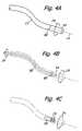
- FIGS. 4A , 4 B, and 4 Cschematically show the principle of an independently rotatable distal section of a flexible endoscope and various ways of actuating this distal section.
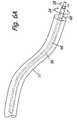
- FIG. 5illustrates a flexible endoscope shaft with a two degree of freedom distal section for variable direction viewing.
- FIG. 6Aschematically shows the principle of concentric flexible drive shafts for actuating two degrees of freedom.
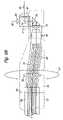
- FIG. 6Bschematically shows the internal structure of the distal section of a flexible variable direction of view endoscope actuated by concentric flexible drive shafts.
- FIGS. 7A and 7Bshow sectionals of embodiments of distal sections of a variable direction of view endoscope.
- FIG. 8illustrates a self-contained distal section of a variable direction of view endoscope containing an image sensor, an optical objective system, electromechanical actuators for two degrees of view vector freedom, and accelerometers for sensing pitch, roll, and yaw.
- FIG. 1shows a parameterization of a rigid variable direction of view endoscope consisting of a handle 10 and a shaft 12 with a longitudinal axis 14 .
- the handle 10can be parameterized by coordinate axes 16 , 18 , 20 which provide a reference frame for describing the relative motion of a variable view vector 22 .
- the view vector 22can be rotated about the longitudinal axis 14 in a first degree of freedom 24 and about a second axis 26 in a second degree of freedom 28 .
- a camera 30(which could also be located in the endoscope tip) produces an image 32 of the endoscopic view 34 . Rotation of the image 32 constitutes a third degree of freedom 36 .
- Encoders and processorsmonitor the states of the three degrees of freedom 24 , 28 , 36 and provide information about the running configuration of the endoscope relative to its default configuration.
- the default configurationis the basic reference state of the endoscope and is important in calculating viewing configurations corresponding to desired views requested by the operator.
- Some variable direction of view endoscopeswill also include accelerometers 38 , 40 , 42 which measure roll, pitch and yaw of the endoscope handle 10 and thus provide the information necessary to enable gravity referenced navigation of the view 34 . Whether the viewing navigation is gravity referenced, view referenced, or scope frame referenced, it fundamentally relies on the rigid and thus measurable relationship between the distal mechanics of the endoscope and its proximal handle 10 .
- FIGS. 2A and 2Brespectively show a flexible endoscope and a flexible endoscope shaft 12 with a deflectable tip 44 actuated by cables 46 connected to distal vertebra 48 .
- the longitudinal axis 14is variable and curvilinear, the direction of view vector 22 relative to the handle 10 and coordinate axes 16 , 18 , 20 is unknown.
- Gravity referenced navigationalso becomes impossible with proximally placed accelerometers because the attitude of the handle 10 is not correlated to the attitude of the endoscope tip.
- FIG. 3illustrates torsional wind-up of a flexible endoscope shaft 12 caused by frictional forces from the surroundings 49 .
- the endoscope handle 10is twisted from an initial configuration to a new configuration through an angle 54 , the proximal end of the endoscope shaft 12 follows the motion of the handle 10 while the distal end only twists through a smaller angle 56 .
- This wind-upis responsible for complete or partial loss of the first degree of freedom.
- FIG. 4Ashows a distal section 54 which is rotatable relative to a stationary shaft 12 .
- the distal section 54is anchored to a flexible drive shaft 56 similar to speedometer cable, as shown in FIG. 4B .
- the drive shaft 56is not subjected to frictional forces from the environment, it can be as compliant as the outside shaft 12 and still provide sufficient torque to the distal section 54 .
- an actuatorsuch as a motor 58 , can be used to rotate the distal section 54 .
- the motor 58could be housed in either the shaft 12 or the distal section 54 .
- the interface 60 between the distal section 54 and the shaft 12can be a rotating seal or it can be covered with a thin sleeve in applications which have strict sterilization requirements.
- These drive mechanismsdo not preclude vertebral or other type of tip deflecting mechanisms positioned in the shaft 12 .
- the second degree of freedom required for variable direction of view endoscopyis typically provided through optical elements configured to rotate about an axis 26 normal to the endoscope longitudinal axis 14 .
- FIG. 5shows a flexible shaft 12 with a rigid distal section 54 having two degrees of freedom 24 , 28 .
- the configuration of the distal section 54which is similar to that disclosed in U.S. Pat. No. 6,648,817 to Schara et al., has a pivotable view vector 22 , a spherical coverglass 62 allowing scanning through a range 64 , and a recessed portion behind the coverglass 62 for maximal retroviewing.
- Illuminationis provided by LED arrays 66 which receive power through a rotating electrical connection (not shown) at the interface 60 . Illumination could also be provided through traditional optical fibers, but this would require either a fiber optic slip ring, as disclosed in U.S. Pat. No. 5,621,830 to Lucey, or slack fibers which would impose a limited travel on the first degree of freedom 24 .
- the second degree of freedom 28can be actuated by another flexible drive shaft 68 routed through the core of the drive shaft 56 which actuates the first degree of freedom 24 , as shown in FIG. 6A .
- This shaft 68is outfitted with a drive gear 70 and mechanically couples to a driven gear 72 , both illustrated in FIG. 6B .
- the driven gear 72houses a first reflector 74 and can be rotated about the axis 26 .
- Light from the environmentis delivered to a fiber optic relay 76 through the coverglass 62 , the first reflector 74 , a second reflector 78 , and a lens train 80 along a folded optical path 82 .
- the hollow drive shaft 68houses the fiber relay 76 and thus accomplishes both mechanical and optical transmission.
- the drive shaft 56is anchored to the distal section 54 and can be rotated independently of the shaft 68 .
- the drive shafts 56 , 68can be arranged concentrically, but this is not necessary.
- FIG. 7Ashows an alternative embodiment of the distal section 54 where the drive shaft for the second degree of freedom has been replaced by a motor 84 , and the fiber optic relay has been substituted with a distal image sensor 86 , eliminating the need for a second reflector in the lens train 80 .
- the reflector 74is driven directly by a hollow-shaft motor 88 without the use of gears 70 , 72 . Both of these designs have the advantage of not needing a lengthy optical transmission system or a lengthy mechanical transmission for the second degree of freedom.
- the first degree of freedom 24can be driven by either a flexible shaft or a distal actuator ( FIGS. 4B , 4 C).
- FIG. 8illustrates distal section 54 as a complete self-contained module which houses actuators 58 , 88 for the two degrees of freedom 24 , 28 , an image sensor 86 with an optical objective system 80 , and accelerometers 38 , 40 , 42 for sensing roll, pitch, and yaw, enabling gravity referenced navigation.
- These accelerometerscould also be placed in the flexible endoscope shaft as long as they are close enough to the tip that there is a fixed geometric relationship between the accelerometers and the tip mechanics.
- the coordinate axes 16 , 18 , 20can be oriented according to a desired parameterization.
- the module 54would also be equipped with a solid state illumination system (not shown) and optionally a battery which would remove the need for supplying power through a rotating electrical connection at the interface 60 .
- a solid state illumination systemnot shown
- a batterywhich would remove the need for supplying power through a rotating electrical connection at the interface 60 .
- the module 54could be made detachable from the main endoscope shaft, possibly affording sterilization, storage, manufacturing, and cost advantages.
- An example of a detachable moduleis the Karl Storz DCI system which has a detachable shaft and optical relay sterilizable separately from a motorized electromechanical imaging unit. However, this system is not multidirectional and also has the actuators and sensors in the proximal rather than distal end.
- the present inventionprovides a flexible endoscope with the capabilities and advantages of a rigid variable direction of view endoscope.
- the modularity of this inventioncould also afford certain advantages to the fields of rigid and semi-flexible variable direction of view endoscopy.
Landscapes
- Health & Medical Sciences (AREA)
- Life Sciences & Earth Sciences (AREA)
- Surgery (AREA)
- Biomedical Technology (AREA)
- Medical Informatics (AREA)
- Optics & Photonics (AREA)
- Pathology (AREA)
- Radiology & Medical Imaging (AREA)
- Biophysics (AREA)
- Engineering & Computer Science (AREA)
- Physics & Mathematics (AREA)
- Heart & Thoracic Surgery (AREA)
- Nuclear Medicine, Radiotherapy & Molecular Imaging (AREA)
- Molecular Biology (AREA)
- Animal Behavior & Ethology (AREA)
- General Health & Medical Sciences (AREA)
- Public Health (AREA)
- Veterinary Medicine (AREA)
- Instruments For Viewing The Inside Of Hollow Bodies (AREA)
- Endoscopes (AREA)
Abstract
Description
- Restricted mobility. Because they must flex in order to change their line of sight, mobility is restricted in small cavities. Specifically, the tip can not actuate properly if it is too close to a wall.
- Unknown viewpoint. It is often difficult for the user to stay oriented when using flexible endoscopes because the view point displaces itself in a confusing way as the tip is flexed. Kanehira (U.S. Pat. No. 3,880,148) tried to solve these problems by incorporating a pivotable distal reflector as seen in rigid variable direction of view scopes, but the design was too complex, and it suffered from another fundamental shortcoming of flexible endoscopes: shaft wind-up.
- Shaft wind-up. A flexible shaft cannot predictably transmit twisting motions. Unlike rigid variable direction of view endoscopes which can rely on rigid transmission of a torsional moment through their shaft to obtain the necessary second degree of view vector freedom at the tip, flexible endoscopes tend to wind up and do not reliably transmit twisting motions from the proximal to the distal end. This is because the surrounding tissue exerts sufficient frictional force to counteract twist force from the operator. This problem is so severe that makers of flexible endoscopes eventually designed four-way tip deflection mechanisms in an attempt to regain some of the mobility lost through shaft wind-up. Stored torsional energy can also cause a wound scope to release unexpectedly, possibly injuring tissue.
- Indeterminate kinematics. Besides reduced controllability from twisting and bending, the flexible nature of the endoscope shaft introduces a further complication: the kinematic relationship between the distal and proximal ends is unknown. Because a flexible shaft accommodates the geometry/topography of its surroundings, the configuration of the endoscope tip and its view vector can not be correctly computed from sensor inputs at the proximal end. This means that unless the tip or shaft is instrumented with sensors, it is impossible to provide advanced navigation features (such as those described by Hale et al.).
- Decoupled viewing process. Another drawback resulting from the mathematical decoupling between the distal and proximal ends is that the scope's viewing direction can not be mentally visualized by the operator during use. Getting an external estimate of where an endoscope is “looking” during a procedure is important as the clinician tries to integrate preexisting knowledge of the anatomy with the viewing process. With rigid fixed-viewing endoscopes the operator can extrapolate the viewing direction as an extension of the longitudinal axis of the endoscope even though the tip is concealed by surrounding tissue. With rigid variable viewing direction instruments the configuration of the view vector is kinematically determinate and so can be presented graphically to the user (Hale et al). Neither of these advantages is possible with current flexible endoscopes.
Claims (20)
Priority Applications (2)
| Application Number | Priority Date | Filing Date | Title |
|---|---|---|---|
| US11/048,021US7344494B2 (en) | 2004-02-09 | 2005-01-31 | Endoscope with variable direction of view module |
| US11/867,103US9591962B2 (en) | 2004-02-09 | 2007-10-04 | Endoscope with variable direction of view module |
Applications Claiming Priority (2)
| Application Number | Priority Date | Filing Date | Title |
|---|---|---|---|
| US54294304P | 2004-02-09 | 2004-02-09 | |
| US11/048,021US7344494B2 (en) | 2004-02-09 | 2005-01-31 | Endoscope with variable direction of view module |
Related Child Applications (1)
| Application Number | Title | Priority Date | Filing Date |
|---|---|---|---|
| US11/867,103ContinuationUS9591962B2 (en) | 2004-02-09 | 2007-10-04 | Endoscope with variable direction of view module |
Publications (2)
| Publication Number | Publication Date |
|---|---|
| US20050177026A1 US20050177026A1 (en) | 2005-08-11 |
| US7344494B2true US7344494B2 (en) | 2008-03-18 |
Family
ID=34829820
Family Applications (2)
| Application Number | Title | Priority Date | Filing Date |
|---|---|---|---|
| US11/048,021Active2025-12-09US7344494B2 (en) | 2004-02-09 | 2005-01-31 | Endoscope with variable direction of view module |
| US11/867,103Active2029-06-30US9591962B2 (en) | 2004-02-09 | 2007-10-04 | Endoscope with variable direction of view module |
Family Applications After (1)
| Application Number | Title | Priority Date | Filing Date |
|---|---|---|---|
| US11/867,103Active2029-06-30US9591962B2 (en) | 2004-02-09 | 2007-10-04 | Endoscope with variable direction of view module |
Country Status (1)
| Country | Link |
|---|---|
| US (2) | US7344494B2 (en) |
Cited By (18)
| Publication number | Priority date | Publication date | Assignee | Title |
|---|---|---|---|---|
| US20090112061A1 (en)* | 2007-10-25 | 2009-04-30 | Dhs Company Ltd. | Endoscope capable of varying field of vision |
| US20090196459A1 (en)* | 2008-02-01 | 2009-08-06 | Perceptron, Inc. | Image manipulation and processing techniques for remote inspection device |
| US20110130616A1 (en)* | 2003-06-18 | 2011-06-02 | Seeney Charles E | Magnetically Responsive Nanoparticle Therapeutic Constructs and Methods of Making and Using |
| US20120078049A1 (en)* | 2010-09-17 | 2012-03-29 | Henke-Sass, Wolf Gmbh | Endoscope with variable direction of view |
| US20120078048A1 (en)* | 2010-09-17 | 2012-03-29 | Henke-Sass, Wolf Gmbh | Endoscope with variable direction of view |
| US20140012080A1 (en)* | 2011-03-10 | 2014-01-09 | Panasonic Corporation | Endoscopic camera and endoscopic device |
| US8758234B2 (en) | 2008-07-08 | 2014-06-24 | Karl Storz Imaging, Inc. | Solid state variable direction of view endoscope |
| US8771177B2 (en) | 2008-07-08 | 2014-07-08 | Karl Storz Imaging, Inc. | Wide angle flexible endoscope |
| US20150031948A1 (en)* | 2006-05-09 | 2015-01-29 | Boston Scientific Scimed, Inc. | Medical device positioning system |
| US9763563B2 (en) | 2012-07-11 | 2017-09-19 | Karl Storz Imaging, Inc. | Endoscopic camera single-button mode activation |
| US9849070B2 (en)* | 2011-08-29 | 2017-12-26 | Art Healthcare Ltd. | Postpyloric feeding device and methods for using thereof |
| US10092169B2 (en) | 2008-07-08 | 2018-10-09 | Karl Storz Imaging, Inc. | Solid state variable direction of view endoscope |
| US10098523B2 (en) | 2015-11-18 | 2018-10-16 | Art Healthcare Ltd. | Sheath and hub for imaging endoscope |
| US10517470B2 (en) | 2016-05-13 | 2019-12-31 | Karl Storz Endovision, Inc. | Optical instrument and articulating image sensing apparatus therefor |
| US11032481B2 (en) | 2018-07-06 | 2021-06-08 | Medos International Sarl | Camera scope electronic variable prism |
| US11202014B2 (en) | 2018-07-06 | 2021-12-14 | Medos International Sari | Camera scope electronic variable angle of view |
| US12070196B2 (en) | 2020-11-23 | 2024-08-27 | Medos International Sarl | Arthroscopic medical implements and assemblies |
| US12220104B2 (en) | 2019-10-07 | 2025-02-11 | S&N Orion Prime, S.A. | Systems and methods for changing the direction of view during video guided clinical procedures using real-time image processing |
Families Citing this family (88)
| Publication number | Priority date | Publication date | Assignee | Title |
|---|---|---|---|---|
| US20070208328A1 (en)* | 1995-08-31 | 2007-09-06 | Dmitri Boutoussov | Contra-angel rotating handpiece having tactile-feedback tip ferrule |
| US8182473B2 (en) | 1999-01-08 | 2012-05-22 | Palomar Medical Technologies | Cooling system for a photocosmetic device |
| US6517532B1 (en) | 1997-05-15 | 2003-02-11 | Palomar Medical Technologies, Inc. | Light energy delivery head |
| ES2226133T3 (en) | 1997-05-15 | 2005-03-16 | Palomar Medical Technologies, Inc. | DERMATOLOGICAL TREATMENT DEVICE. |
| ES2245506T3 (en) | 1998-03-12 | 2006-01-01 | Palomar Medical Technologies, Inc. | ELECTROMAGNETIC RADIATION APPLICATION SYSTEM ON SKIN. |
| WO2004000098A2 (en) | 2002-06-19 | 2003-12-31 | Palomar Medical Technologies, Inc. | Method and apparatus for treatment of cutaneous and subcutaneous conditions |
| EP2522294A2 (en) | 2002-10-23 | 2012-11-14 | Palomar Medical Technologies, Inc. | Phototreatment device for use with coolants and topical substances |
| WO2009058350A1 (en)* | 2007-11-02 | 2009-05-07 | The Trustees Of Columbia University In The City Of New York | Insertable surgical imaging device |
| US7292759B2 (en)* | 2005-06-07 | 2007-11-06 | Biolase Technology, Inc. | Contra-angle rotating handpiece having tactile-feedback tip ferrule |
| US7909756B2 (en)* | 2005-01-26 | 2011-03-22 | Karl Storz Imaging, Inc. | Illumination system for variable direction of view instruments |
| US7856985B2 (en) | 2005-04-22 | 2010-12-28 | Cynosure, Inc. | Method of treatment body tissue using a non-uniform laser beam |
| US20090067189A1 (en)* | 2005-06-07 | 2009-03-12 | Dmitri Boutoussov | Contra-angle rotating handpiece having tactile-feedback tip ferrule |
| CN101309631A (en) | 2005-09-15 | 2008-11-19 | 帕洛玛医疗技术公司 | Skin optical characterization device |
| JP4545696B2 (en)* | 2005-09-30 | 2010-09-15 | 富士フイルム株式会社 | Optical probe |
| EP1891882A3 (en)* | 2006-04-05 | 2008-12-31 | Arthrex, Inc. | Deflectable tip videoarthroscope |
| US7586957B2 (en) | 2006-08-02 | 2009-09-08 | Cynosure, Inc | Picosecond laser apparatus and methods for its operation and use |
| US20080112885A1 (en) | 2006-09-06 | 2008-05-15 | Innurvation, Inc. | System and Method for Acoustic Data Transmission |
| US8529441B2 (en) | 2008-02-12 | 2013-09-10 | Innurvation, Inc. | Ingestible endoscopic optical scanning device |
| US20100016662A1 (en)* | 2008-02-21 | 2010-01-21 | Innurvation, Inc. | Radial Scanner Imaging System |
| US8617058B2 (en) | 2008-07-09 | 2013-12-31 | Innurvation, Inc. | Displaying image data from a scanner capsule |
| JP5477294B2 (en)* | 2008-10-20 | 2014-04-23 | コニカミノルタ株式会社 | Optical rotating probe |
| DE102009013761A1 (en)* | 2009-03-17 | 2010-09-23 | Fraunhofer-Gesellschaft zur Förderung der angewandten Forschung e.V. | An endoscope and an imaging device |
| US9919168B2 (en) | 2009-07-23 | 2018-03-20 | Palomar Medical Technologies, Inc. | Method for improvement of cellulite appearance |
| US8647259B2 (en) | 2010-03-26 | 2014-02-11 | Innurvation, Inc. | Ultrasound scanning capsule endoscope (USCE) |
| WO2011143269A1 (en)* | 2010-05-10 | 2011-11-17 | Nanamed, Llc | Method and endoscopic device for examining or imaging an interior surface of a corporeal cavity |
| US20120116213A1 (en)* | 2010-11-09 | 2012-05-10 | Forster David C | Orientation determination of a medical device within a patient |
| CN102525386B (en) | 2010-12-17 | 2015-11-25 | 世意法(北京)半导体研发有限责任公司 | Capsule endoscope |
| US11412998B2 (en) | 2011-02-10 | 2022-08-16 | Karl Storz Imaging, Inc. | Multi-source medical display |
| US10631712B2 (en) | 2011-02-10 | 2020-04-28 | Karl Storz Imaging, Inc. | Surgeon's aid for medical display |
| US10674968B2 (en)* | 2011-02-10 | 2020-06-09 | Karl Storz Imaging, Inc. | Adjustable overlay patterns for medical display |
| WO2013009887A1 (en) | 2011-07-11 | 2013-01-17 | Board Of Regents Of The University Of Nebraska | Robotic surgical devices, systems and related methods |
| US20130079644A1 (en)* | 2011-09-23 | 2013-03-28 | Tyco Electronics Corporation | Optical Probe with Electric Motor |
| EP2574268B1 (en)* | 2011-09-30 | 2017-07-12 | Karl Storz GmbH & Co. KG | Endoscope with adjustable view angle |
| WO2013052137A2 (en) | 2011-10-03 | 2013-04-11 | Board Of Regents Of The University Of Nebraska | Robotic surgical devices, systems and related methods |
| JPWO2013069382A1 (en) | 2011-11-09 | 2015-04-02 | オリンパス株式会社 | Endoscope |
| ES2951058T3 (en)* | 2012-03-09 | 2023-10-17 | 3Shape As | 3D scanner with steam autoclavable tip containing a heated optical element |
| EP2832282A4 (en)* | 2012-03-30 | 2015-12-02 | Olympus Corp | Insertion device, rotating tubular member and drive unit |
| EP2839552A4 (en) | 2012-04-18 | 2015-12-30 | Cynosure Inc | PICOSECOND LASER APPARATUS AND METHOD OF PROCESSING TARGET TISSUES USING THE SAME |
| EP2844181B1 (en) | 2012-05-01 | 2021-03-10 | Board of Regents of the University of Nebraska | Single site robotic device and related systems |
| US20130317519A1 (en) | 2012-05-25 | 2013-11-28 | Hansen Medical, Inc. | Low friction instrument driver interface for robotic systems |
| US12295680B2 (en) | 2012-08-08 | 2025-05-13 | Board Of Regents Of The University Of Nebraska | Robotic surgical devices, systems and related methods |
| EP2882331A4 (en) | 2012-08-08 | 2016-03-23 | Univ Nebraska | ROBOTIC SURGICAL SYSTEMS AND DEVICES, AND ASSOCIATED METHODS |
| US9408527B2 (en)* | 2012-11-01 | 2016-08-09 | Karl Storz Imaging, Inc. | Solid state variable direction of view endoscope with rotatable wide-angle field for maximal image performance |
| CA2906672C (en) | 2013-03-14 | 2022-03-15 | Board Of Regents Of The University Of Nebraska | Methods, systems, and devices relating to force control surgical systems |
| US9173713B2 (en) | 2013-03-14 | 2015-11-03 | Hansen Medical, Inc. | Torque-based catheter articulation |
| US9326822B2 (en) | 2013-03-14 | 2016-05-03 | Hansen Medical, Inc. | Active drives for robotic catheter manipulators |
| US20140277334A1 (en) | 2013-03-14 | 2014-09-18 | Hansen Medical, Inc. | Active drives for robotic catheter manipulators |
| US11213363B2 (en) | 2013-03-14 | 2022-01-04 | Auris Health, Inc. | Catheter tension sensing |
| US10285757B2 (en) | 2013-03-15 | 2019-05-14 | Cynosure, Llc | Picosecond optical radiation systems and methods of use |
| US20140276647A1 (en) | 2013-03-15 | 2014-09-18 | Hansen Medical, Inc. | Vascular remote catheter manipulator |
| US20140276936A1 (en) | 2013-03-15 | 2014-09-18 | Hansen Medical, Inc. | Active drive mechanism for simultaneous rotation and translation |
| US9408669B2 (en) | 2013-03-15 | 2016-08-09 | Hansen Medical, Inc. | Active drive mechanism with finite range of motion |
| US10966700B2 (en) | 2013-07-17 | 2021-04-06 | Virtual Incision Corporation | Robotic surgical devices, systems and related methods |
| US10046140B2 (en) | 2014-04-21 | 2018-08-14 | Hansen Medical, Inc. | Devices, systems, and methods for controlling active drive systems |
| US10569052B2 (en) | 2014-05-15 | 2020-02-25 | Auris Health, Inc. | Anti-buckling mechanisms for catheters |
| US9561083B2 (en) | 2014-07-01 | 2017-02-07 | Auris Surgical Robotics, Inc. | Articulating flexible endoscopic tool with roll capabilities |
| EP3217890B1 (en) | 2014-11-11 | 2020-04-08 | Board of Regents of the University of Nebraska | Robotic device with compact joint design |
| JP6116780B1 (en)* | 2015-07-14 | 2017-04-19 | オリンパス株式会社 | Endoscope |
| WO2017024081A1 (en) | 2015-08-03 | 2017-02-09 | Board Of Regents Of The University Of Nebraska | Robotic surgical devices systems and related methods |
| CN108348133B (en) | 2015-09-09 | 2020-11-13 | 奥瑞斯健康公司 | Instrument Manipulators for Surgical Robotic Systems |
| US9955986B2 (en) | 2015-10-30 | 2018-05-01 | Auris Surgical Robotics, Inc. | Basket apparatus |
| US10231793B2 (en) | 2015-10-30 | 2019-03-19 | Auris Health, Inc. | Object removal through a percutaneous suction tube |
| US9949749B2 (en) | 2015-10-30 | 2018-04-24 | Auris Surgical Robotics, Inc. | Object capture with a basket |
| WO2017183196A1 (en)* | 2016-04-22 | 2017-10-26 | オリンパス株式会社 | Flexible tube insertion device |
| US10454347B2 (en) | 2016-04-29 | 2019-10-22 | Auris Health, Inc. | Compact height torque sensing articulation axis assembly |
| CA3024623A1 (en) | 2016-05-18 | 2017-11-23 | Virtual Incision Corporation | Robotic surgical devices, systems and related methods |
| US11241559B2 (en) | 2016-08-29 | 2022-02-08 | Auris Health, Inc. | Active drive for guidewire manipulation |
| WO2018045036A1 (en) | 2016-08-30 | 2018-03-08 | Board Of Regents Of The University Of Nebraska | Robotic device with compact joint design and an additional degree of freedom and related systems and methods |
| KR20230096148A (en) | 2016-08-31 | 2023-06-29 | 아우리스 헬스, 인코포레이티드 | Length conservative surgical instrument |
| US10244926B2 (en) | 2016-12-28 | 2019-04-02 | Auris Health, Inc. | Detecting endolumenal buckling of flexible instruments |
| US11026758B2 (en) | 2017-06-28 | 2021-06-08 | Auris Health, Inc. | Medical robotics systems implementing axis constraints during actuation of one or more motorized joints |
| WO2019012824A1 (en)* | 2017-07-13 | 2019-01-17 | オリンパス株式会社 | Endoscope |
| CN117017492A (en) | 2017-09-27 | 2023-11-10 | 虚拟切割有限公司 | Robotic surgical device with tracking camera technology and related systems and methods |
| CN111770736A (en) | 2017-12-11 | 2020-10-13 | 奥瑞斯健康公司 | Systems and methods for instrument-based insertion architectures |
| US11510736B2 (en) | 2017-12-14 | 2022-11-29 | Auris Health, Inc. | System and method for estimating instrument location |
| CA3087672A1 (en) | 2018-01-05 | 2019-07-11 | Board Of Regents Of The University Of Nebraska | Single-arm robotic device with compact joint design and related systems and methods |
| EP3740150A4 (en) | 2018-01-17 | 2021-11-03 | Auris Health, Inc. | SURGICAL ROBOTIC SYSTEMS WITH IMPROVED ROBOTIC ARMS |
| WO2019165426A1 (en) | 2018-02-26 | 2019-08-29 | Cynosure, Inc. | Q-switched cavity dumped sub-nanosecond laser |
| KR102712920B1 (en) | 2018-06-27 | 2024-10-07 | 아우리스 헬스, 인코포레이티드 | Alignment and attachment systems for medical devices |
| WO2020012576A1 (en)* | 2018-07-11 | 2020-01-16 | オリンパス株式会社 | Endoscope system, method of calibrating endoscope, and device for controlling endoscope |
| WO2020069080A1 (en) | 2018-09-28 | 2020-04-02 | Auris Health, Inc. | Devices, systems, and methods for manually and robotically driving medical instruments |
| WO2020146348A1 (en) | 2019-01-07 | 2020-07-16 | Virtual Incision Corporation | Robotically assisted surgical system and related devices and methods |
| WO2020197671A1 (en) | 2019-03-22 | 2020-10-01 | Auris Health, Inc. | Systems and methods for aligning inputs on medical instruments |
| US11896330B2 (en) | 2019-08-15 | 2024-02-13 | Auris Health, Inc. | Robotic medical system having multiple medical instruments |
| US11737845B2 (en) | 2019-09-30 | 2023-08-29 | Auris Inc. | Medical instrument with a capstan |
| EP4084724A4 (en) | 2019-12-31 | 2023-12-27 | Auris Health, Inc. | ADVANCED BASKET DRIVE MODE |
| CN114901188A (en) | 2019-12-31 | 2022-08-12 | 奥瑞斯健康公司 | Dynamic pulley system |
| US20250052996A1 (en)* | 2023-08-08 | 2025-02-13 | Baker Hughes Holdings Llc | Automatic slap impact mitigation system |
Citations (25)
| Publication number | Priority date | Publication date | Assignee | Title |
|---|---|---|---|---|
| US3856000A (en) | 1972-06-19 | 1974-12-24 | Machido Seisakusho Kk | Endoscope |
| US3880148A (en) | 1972-09-25 | 1975-04-29 | Olympus Optical Co | Endoscope |
| US4037938A (en) | 1974-11-27 | 1977-07-26 | Olympus Optical Co., Ltd. | Retrofocus-type objective for endoscopes |
| US4042295A (en) | 1974-10-15 | 1977-08-16 | Olympus Optical Co., Inc. | Retrofocus-type objective for endoscopes |
| US4140364A (en) | 1973-06-23 | 1979-02-20 | Olympus Optical Co., Ltd. | Variable field optical system for endoscopes |
| US4598980A (en) | 1983-07-23 | 1986-07-08 | Fuji Photo Optical Co., Ltd. | Objective optical system for endoscope |
| US4697577A (en) | 1986-05-22 | 1987-10-06 | Baxter Travenol Laboratories, Inc. | Scanning microtelescope for surgical applications |
| US5313306A (en) | 1991-05-13 | 1994-05-17 | Telerobotics International, Inc. | Omniview motionless camera endoscopy system |
| US5524180A (en) | 1992-08-10 | 1996-06-04 | Computer Motion, Inc. | Automated endoscope system for optimal positioning |
| US5762603A (en) | 1995-09-15 | 1998-06-09 | Pinotage, Llc | Endoscope having elevation and azimuth control of camera assembly |
| US5800341A (en) | 1994-03-30 | 1998-09-01 | Medical Media Systems | Electronically steerable endoscope |
| WO1999042028A1 (en) | 1998-02-19 | 1999-08-26 | California Institute Of Technology | Apparatus and method for providing spherical viewing during endoscopic procedures |
| DE29907430U1 (en) | 1999-04-27 | 1999-09-16 | Schich, Gisbert, 91522 Ansbach | Endoscope with rotating optics |
| US6097423A (en) | 1997-06-06 | 2000-08-01 | Karl Storz Imaging, Inc. | Image orientation for endoscopic video displays |
| US6190309B1 (en)* | 1997-11-07 | 2001-02-20 | Matsushita Electric Industrial Co., Ltd. | Video scope and portable accommodation case therefor |
| WO2001022865A1 (en) | 1999-09-28 | 2001-04-05 | Keymed (Medical & Industrial Equipment) Ltd. | Endoscope with variable direction of view |
| US20010031912A1 (en) | 2000-04-10 | 2001-10-18 | Cbeyond Inc. | Image sensor and an endoscope using the same |
| US20010035902A1 (en) | 2000-03-08 | 2001-11-01 | Iddan Gavriel J. | Device and system for in vivo imaging |
| US20020068853A1 (en) | 2000-04-10 | 2002-06-06 | Doron Adler | Intra vascular imaging method and apparatus |
| US6500115B2 (en) | 1998-08-28 | 2002-12-31 | Storz Endoskop Gmbh | Endoscope |
| US6648817B2 (en) | 2001-11-15 | 2003-11-18 | Endactive, Inc. | Apparatus and method for stereo viewing in variable direction-of-view endoscopy |
| US6663559B2 (en) | 2001-12-14 | 2003-12-16 | Endactive, Inc. | Interface for a variable direction of view endoscope |
| US20040249247A1 (en)* | 2003-05-01 | 2004-12-09 | Iddan Gavriel J. | Endoscope with panoramic view |
| US20050085698A1 (en)* | 2003-10-16 | 2005-04-21 | Snecma Moteurs | Endoscope with ultraviolet illumination |
| US6958034B2 (en)* | 2002-02-11 | 2005-10-25 | Given Imaging Ltd. | Self propelled device |
Family Cites Families (7)
| Publication number | Priority date | Publication date | Assignee | Title |
|---|---|---|---|---|
| US5019121A (en)* | 1990-05-25 | 1991-05-28 | Welch Allyn, Inc. | Helical fluid-actuated torsional motor |
| US6134003A (en)* | 1991-04-29 | 2000-10-17 | Massachusetts Institute Of Technology | Method and apparatus for performing optical measurements using a fiber optic imaging guidewire, catheter or endoscope |
| US6450950B2 (en)* | 1992-11-12 | 2002-09-17 | Karl Storz Gmbh & Co. Kg | Endoscope having stereo-lateral-view optics |
| WO1996002184A1 (en)* | 1994-07-14 | 1996-02-01 | Washington Research Foundation | Method and apparatus for detecting barrett's metaplasia of the esophagus |
| US6478730B1 (en)* | 1998-09-09 | 2002-11-12 | Visionscope, Inc. | Zoom laparoscope |
| US6879851B2 (en)* | 2001-06-07 | 2005-04-12 | Lightlab Imaging, Llc | Fiber optic endoscopic gastrointestinal probe |
| FR2832516B1 (en)* | 2001-11-19 | 2004-01-23 | Tokendo Sarl | ROTARY ENDOSCOPES WITH A DEVIED DISTAL VIEW |
- 2005
- 2005-01-31USUS11/048,021patent/US7344494B2/enactiveActive
- 2007
- 2007-10-04USUS11/867,103patent/US9591962B2/enactiveActive
Patent Citations (27)
| Publication number | Priority date | Publication date | Assignee | Title |
|---|---|---|---|---|
| US3856000A (en) | 1972-06-19 | 1974-12-24 | Machido Seisakusho Kk | Endoscope |
| US3880148A (en) | 1972-09-25 | 1975-04-29 | Olympus Optical Co | Endoscope |
| US4140364A (en) | 1973-06-23 | 1979-02-20 | Olympus Optical Co., Ltd. | Variable field optical system for endoscopes |
| US4042295A (en) | 1974-10-15 | 1977-08-16 | Olympus Optical Co., Inc. | Retrofocus-type objective for endoscopes |
| US4037938A (en) | 1974-11-27 | 1977-07-26 | Olympus Optical Co., Ltd. | Retrofocus-type objective for endoscopes |
| US4598980A (en) | 1983-07-23 | 1986-07-08 | Fuji Photo Optical Co., Ltd. | Objective optical system for endoscope |
| US4697577A (en) | 1986-05-22 | 1987-10-06 | Baxter Travenol Laboratories, Inc. | Scanning microtelescope for surgical applications |
| US5313306A (en) | 1991-05-13 | 1994-05-17 | Telerobotics International, Inc. | Omniview motionless camera endoscopy system |
| US5524180A (en) | 1992-08-10 | 1996-06-04 | Computer Motion, Inc. | Automated endoscope system for optimal positioning |
| US5800341A (en) | 1994-03-30 | 1998-09-01 | Medical Media Systems | Electronically steerable endoscope |
| US5762603A (en) | 1995-09-15 | 1998-06-09 | Pinotage, Llc | Endoscope having elevation and azimuth control of camera assembly |
| US6097423A (en) | 1997-06-06 | 2000-08-01 | Karl Storz Imaging, Inc. | Image orientation for endoscopic video displays |
| US6190309B1 (en)* | 1997-11-07 | 2001-02-20 | Matsushita Electric Industrial Co., Ltd. | Video scope and portable accommodation case therefor |
| US6371909B1 (en) | 1998-02-19 | 2002-04-16 | California Institute Of Technology | Apparatus and method for providing spherical viewing during endoscopic procedures |
| WO1999042028A1 (en) | 1998-02-19 | 1999-08-26 | California Institute Of Technology | Apparatus and method for providing spherical viewing during endoscopic procedures |
| US6500115B2 (en) | 1998-08-28 | 2002-12-31 | Storz Endoskop Gmbh | Endoscope |
| DE29907430U1 (en) | 1999-04-27 | 1999-09-16 | Schich, Gisbert, 91522 Ansbach | Endoscope with rotating optics |
| WO2001022865A1 (en) | 1999-09-28 | 2001-04-05 | Keymed (Medical & Industrial Equipment) Ltd. | Endoscope with variable direction of view |
| US6560013B1 (en) | 1999-09-28 | 2003-05-06 | Keymed (Medical & Industrial Equipment) Ltd. | Endoscope with variable direction of view |
| US20010035902A1 (en) | 2000-03-08 | 2001-11-01 | Iddan Gavriel J. | Device and system for in vivo imaging |
| US20020068853A1 (en) | 2000-04-10 | 2002-06-06 | Doron Adler | Intra vascular imaging method and apparatus |
| US20010031912A1 (en) | 2000-04-10 | 2001-10-18 | Cbeyond Inc. | Image sensor and an endoscope using the same |
| US6648817B2 (en) | 2001-11-15 | 2003-11-18 | Endactive, Inc. | Apparatus and method for stereo viewing in variable direction-of-view endoscopy |
| US6663559B2 (en) | 2001-12-14 | 2003-12-16 | Endactive, Inc. | Interface for a variable direction of view endoscope |
| US6958034B2 (en)* | 2002-02-11 | 2005-10-25 | Given Imaging Ltd. | Self propelled device |
| US20040249247A1 (en)* | 2003-05-01 | 2004-12-09 | Iddan Gavriel J. | Endoscope with panoramic view |
| US20050085698A1 (en)* | 2003-10-16 | 2005-04-21 | Snecma Moteurs | Endoscope with ultraviolet illumination |
Cited By (31)
| Publication number | Priority date | Publication date | Assignee | Title |
|---|---|---|---|---|
| US20110130616A1 (en)* | 2003-06-18 | 2011-06-02 | Seeney Charles E | Magnetically Responsive Nanoparticle Therapeutic Constructs and Methods of Making and Using |
| US20150031948A1 (en)* | 2006-05-09 | 2015-01-29 | Boston Scientific Scimed, Inc. | Medical device positioning system |
| US20190046009A1 (en)* | 2006-05-09 | 2019-02-14 | Boston Scientific Scimed, Inc. | Medical device positioning system |
| US10136796B2 (en)* | 2006-05-09 | 2018-11-27 | Boston Scientific Scimed, Inc. | Medical device positioning system |
| US11284778B2 (en) | 2006-05-09 | 2022-03-29 | Boston Scientific Scimed, Inc. | Medical device positioning system |
| US11937774B2 (en) | 2006-05-09 | 2024-03-26 | Boston Scientific Scimed, Inc. | Medical device positioning system |
| US10561301B2 (en) | 2006-05-09 | 2020-02-18 | Boston Scientific Scimed, Inc. | Medical device positioning system |
| US20090112061A1 (en)* | 2007-10-25 | 2009-04-30 | Dhs Company Ltd. | Endoscope capable of varying field of vision |
| US20090196459A1 (en)* | 2008-02-01 | 2009-08-06 | Perceptron, Inc. | Image manipulation and processing techniques for remote inspection device |
| US8758234B2 (en) | 2008-07-08 | 2014-06-24 | Karl Storz Imaging, Inc. | Solid state variable direction of view endoscope |
| US10092169B2 (en) | 2008-07-08 | 2018-10-09 | Karl Storz Imaging, Inc. | Solid state variable direction of view endoscope |
| US8992423B2 (en) | 2008-07-08 | 2015-03-31 | Karl Storz Imaging, Inc. | Solid state variable direction of view endoscope |
| US8771177B2 (en) | 2008-07-08 | 2014-07-08 | Karl Storz Imaging, Inc. | Wide angle flexible endoscope |
| US8790252B2 (en)* | 2010-09-17 | 2014-07-29 | Henke-Sass, Wolf Gmbh | Endoscope with variable direction of view |
| US8852086B2 (en)* | 2010-09-17 | 2014-10-07 | Henke-Sass, Wolf Gmbh | Endoscope with variable direction of view |
| US20120078048A1 (en)* | 2010-09-17 | 2012-03-29 | Henke-Sass, Wolf Gmbh | Endoscope with variable direction of view |
| US20120078049A1 (en)* | 2010-09-17 | 2012-03-29 | Henke-Sass, Wolf Gmbh | Endoscope with variable direction of view |
| US9649016B2 (en)* | 2011-03-10 | 2017-05-16 | Panasonic Intellectual Property Management Co., Ltd. | Endoscopic camera and endoscopic device |
| US20140012080A1 (en)* | 2011-03-10 | 2014-01-09 | Panasonic Corporation | Endoscopic camera and endoscopic device |
| US9849070B2 (en)* | 2011-08-29 | 2017-12-26 | Art Healthcare Ltd. | Postpyloric feeding device and methods for using thereof |
| US9763563B2 (en) | 2012-07-11 | 2017-09-19 | Karl Storz Imaging, Inc. | Endoscopic camera single-button mode activation |
| US10588493B2 (en) | 2015-11-18 | 2020-03-17 | Art Healthcare Ltd. | Sheath and hub for imaging endoscope |
| US10098523B2 (en) | 2015-11-18 | 2018-10-16 | Art Healthcare Ltd. | Sheath and hub for imaging endoscope |
| US10517470B2 (en) | 2016-05-13 | 2019-12-31 | Karl Storz Endovision, Inc. | Optical instrument and articulating image sensing apparatus therefor |
| US11032481B2 (en) | 2018-07-06 | 2021-06-08 | Medos International Sarl | Camera scope electronic variable prism |
| US11202014B2 (en) | 2018-07-06 | 2021-12-14 | Medos International Sari | Camera scope electronic variable angle of view |
| US11317029B2 (en) | 2018-07-06 | 2022-04-26 | Medos International Sarl | Camera scope electronic variable prism |
| US12082772B2 (en) | 2018-07-06 | 2024-09-10 | Medos International Sarl | Camera scope electronic variable prism |
| US12200364B2 (en) | 2018-07-06 | 2025-01-14 | Medos International Sarl | Camera scope electronic variable prism |
| US12220104B2 (en) | 2019-10-07 | 2025-02-11 | S&N Orion Prime, S.A. | Systems and methods for changing the direction of view during video guided clinical procedures using real-time image processing |
| US12070196B2 (en) | 2020-11-23 | 2024-08-27 | Medos International Sarl | Arthroscopic medical implements and assemblies |
Also Published As
| Publication number | Publication date |
|---|---|
| US20080021282A1 (en) | 2008-01-24 |
| US9591962B2 (en) | 2017-03-14 |
| US20050177026A1 (en) | 2005-08-11 |
Similar Documents
| Publication | Publication Date | Title |
|---|---|---|
| US7344494B2 (en) | Endoscope with variable direction of view module | |
| US12419713B2 (en) | Surgical instrument with sensor aligned cable guide | |
| JP3610110B2 (en) | Medical manipulator | |
| US6695774B2 (en) | Apparatus and method for controlling endoscopic instruments | |
| EP2064984B1 (en) | Therapeutic device system and manipulator system | |
| CN107530134B (en) | Electromechanical Surgical System | |
| US6197017B1 (en) | Articulated apparatus for telemanipulator system | |
| US6432112B2 (en) | Articulated apparatus for telemanipulator system | |
| Szewczyk et al. | An active tubular polyarticulated micro-system for flexible endoscope | |
| JP2011530373A (en) | System with laparoscopic operation with DOF N | |
| EP0587506A1 (en) | Control mechanism for steerable elongated probe | |
| CN116098713B (en) | Main wrist, main operating equipment and surgical robot | |
| CN101610710A (en) | Multi-joint bending mechanism and multi-joint medical device with multi-joint bending mechanism | |
| US10251532B2 (en) | Method and system for using a variable direction of view endoscope with a robotic endoscope holder | |
| KR20110008189A (en) | Coupler for transferring controller motion from the robot manipulator to the attached instrument | |
| KR102754144B1 (en) | multi-joint type surgical device | |
| US20250186149A1 (en) | End effector unit, surgical tool device, arm device, and master-slave system | |
| JP3679440B2 (en) | Medical manipulator | |
| JP3628742B2 (en) | Medical manipulator | |
| US20220354346A1 (en) | Endoscope | |
| US7273450B2 (en) | Stereoscopic observation system | |
| CN217566304U (en) | Medical robot with image system | |
| WO2019012824A1 (en) | Endoscope | |
| US10674893B2 (en) | Endoscopic surgical device and guide device | |
| CN220898786U (en) | Actuator joint seat, surgical instrument and surgical robot |
Legal Events
| Date | Code | Title | Description |
|---|---|---|---|
| AS | Assignment | Owner name:KARL STORZ DEVELOPMENT CORPORATION, CALIFORNIA Free format text:ASSIGNMENT OF ASSIGNORS INTEREST;ASSIGNOR:ENDACTIVE, INC;REEL/FRAME:016446/0734 Effective date:20050701 | |
| AS | Assignment | Owner name:KARL STORZ DEVELOPMENT CORP., CALIFORNIA Free format text:CORRECTIVE ASSIGNMENT TO CORRECT THE ASSIGNEE NAME PREVIOUSLY RECORDED ON REEL 016446 FRAME 0734. ASSIGNOR(S) HEREBY CONFIRMS THE ASSIGNMENT OF ASSIGNOR'S INTEREST;ASSIGNOR:ENDACTIVE, INC;REEL/FRAME:016522/0966 Effective date:20050701 Owner name:KARL STORZ DEVELOPMENT CORP., CALIFORNIA Free format text:CORRECTIVE ASSIGNMENT TO CORRECT THE ASSIGNEE NAME PREVIOUSLY RECORDED ON REEL 016446 FRAME 0734;ASSIGNOR:ENDACTIVE, INC;REEL/FRAME:016522/0966 Effective date:20050701 | |
| AS | Assignment | Owner name:ENDACTIVE, INC., CALIFORNIA Free format text:ASSIGNMENT OF ASSIGNORS INTEREST;ASSIGNORS:HALE, ERIC L.;HOEG, HANS DAVID;SCHARA, NATHAN JON;REEL/FRAME:018505/0657 Effective date:20061023 | |
| STCF | Information on status: patent grant | Free format text:PATENTED CASE | |
| AS | Assignment | Owner name:KARL STORZ IMAGING, INC., CALIFORNIA Free format text:NUNC PRO TUNC ASSIGNMENT;ASSIGNOR:KARL STORZ DEVELOPMENT CORP.;REEL/FRAME:025114/0991 Effective date:20101004 | |
| FEPP | Fee payment procedure | Free format text:PAT HOLDER NO LONGER CLAIMS SMALL ENTITY STATUS, ENTITY STATUS SET TO UNDISCOUNTED (ORIGINAL EVENT CODE: STOL); ENTITY STATUS OF PATENT OWNER: LARGE ENTITY | |
| FPAY | Fee payment | Year of fee payment:4 | |
| FPAY | Fee payment | Year of fee payment:8 | |
| MAFP | Maintenance fee payment | Free format text:PAYMENT OF MAINTENANCE FEE, 12TH YEAR, LARGE ENTITY (ORIGINAL EVENT CODE: M1553); ENTITY STATUS OF PATENT OWNER: LARGE ENTITY Year of fee payment:12 |