US7344481B2 - Treadmill with moveable console - Google Patents
Treadmill with moveable consoleDownload PDFInfo
- Publication number
- US7344481B2 US7344481B2US10/754,166US75416604AUS7344481B2US 7344481 B2US7344481 B2US 7344481B2US 75416604 AUS75416604 AUS 75416604AUS 7344481 B2US7344481 B2US 7344481B2
- Authority
- US
- United States
- Prior art keywords
- console
- height
- user
- treadmill
- cushioning
- Prior art date
- Legal status (The legal status is an assumption and is not a legal conclusion. Google has not performed a legal analysis and makes no representation as to the accuracy of the status listed.)
- Active, expires
Links
Images


Classifications
- A—HUMAN NECESSITIES
- A63—SPORTS; GAMES; AMUSEMENTS
- A63B—APPARATUS FOR PHYSICAL TRAINING, GYMNASTICS, SWIMMING, CLIMBING, OR FENCING; BALL GAMES; TRAINING EQUIPMENT
- A63B22/00—Exercising apparatus specially adapted for conditioning the cardio-vascular system, for training agility or co-ordination of movements
- A63B22/02—Exercising apparatus specially adapted for conditioning the cardio-vascular system, for training agility or co-ordination of movements with movable endless bands, e.g. treadmills
- A63B22/0207—Exercising apparatus specially adapted for conditioning the cardio-vascular system, for training agility or co-ordination of movements with movable endless bands, e.g. treadmills having shock absorbing means
- A63B22/0221—Exercising apparatus specially adapted for conditioning the cardio-vascular system, for training agility or co-ordination of movements with movable endless bands, e.g. treadmills having shock absorbing means on the frame supporting the rollers
- A—HUMAN NECESSITIES
- A63—SPORTS; GAMES; AMUSEMENTS
- A63B—APPARATUS FOR PHYSICAL TRAINING, GYMNASTICS, SWIMMING, CLIMBING, OR FENCING; BALL GAMES; TRAINING EQUIPMENT
- A63B22/00—Exercising apparatus specially adapted for conditioning the cardio-vascular system, for training agility or co-ordination of movements
- A63B22/02—Exercising apparatus specially adapted for conditioning the cardio-vascular system, for training agility or co-ordination of movements with movable endless bands, e.g. treadmills
- A63B22/0235—Exercising apparatus specially adapted for conditioning the cardio-vascular system, for training agility or co-ordination of movements with movable endless bands, e.g. treadmills driven by a motor
- A63B22/0242—Exercising apparatus specially adapted for conditioning the cardio-vascular system, for training agility or co-ordination of movements with movable endless bands, e.g. treadmills driven by a motor with speed variation
- A63B22/025—Exercising apparatus specially adapted for conditioning the cardio-vascular system, for training agility or co-ordination of movements with movable endless bands, e.g. treadmills driven by a motor with speed variation electrically, e.g. D.C. motors with variable speed control
- A—HUMAN NECESSITIES
- A63—SPORTS; GAMES; AMUSEMENTS
- A63B—APPARATUS FOR PHYSICAL TRAINING, GYMNASTICS, SWIMMING, CLIMBING, OR FENCING; BALL GAMES; TRAINING EQUIPMENT
- A63B2208/00—Characteristics or parameters related to the user or player
- A63B2208/12—Characteristics or parameters related to the user or player specially adapted for children
- A—HUMAN NECESSITIES
- A63—SPORTS; GAMES; AMUSEMENTS
- A63B—APPARATUS FOR PHYSICAL TRAINING, GYMNASTICS, SWIMMING, CLIMBING, OR FENCING; BALL GAMES; TRAINING EQUIPMENT
- A63B2225/00—Miscellaneous features of sport apparatus, devices or equipment
- A63B2225/09—Adjustable dimensions
- A63B2225/093—Height
- A—HUMAN NECESSITIES
- A63—SPORTS; GAMES; AMUSEMENTS
- A63B—APPARATUS FOR PHYSICAL TRAINING, GYMNASTICS, SWIMMING, CLIMBING, OR FENCING; BALL GAMES; TRAINING EQUIPMENT
- A63B2225/00—Miscellaneous features of sport apparatus, devices or equipment
- A63B2225/09—Adjustable dimensions
- A63B2225/096—Adjustable dimensions automatically adjusted according to anthropometric data of the user
Definitions
- the present inventionrelates to exercise apparatuses.
- the present inventionrelates to a self-adjusting treadmill having a movable console and/or a self adjusting cushioning assembly.
- Exercise treadmillshave long been a mainstay of the home and institutional exercise equipment market.
- One advantage of exercise treadmillsis that they decrease the wear on a user's joints when the user is running or walking, as opposed to walking on a street, trail, or other hard and/or uneven surface.
- Exercise treadmills having adjustable features that allow tailoring of the exercise experience to an individual userhave become more popular in recent years.
- Exercise treadmillstypically utilize a console having user interfaces to allow a user to view exercise program information and input or select different exercise program information or features.
- Such consolestypically allow a user some degree of interactivity and tailoring of treadmill features including speed, displayed information, and exercise program duration.
- the height of such consolesis typically set at an intermediate height so as to be usable by most users. However, the intermediate height of the console may not be optimal for many of the users who will utilize the treadmill. Manipulation of the controls, while possible for many users, may not be well tailored to any actual user of the treadmill. Additionally, the height of the console may not comport with a unusually tall or unusually short user. 3
- cushioning mechanismsprovide alleviation from the impact experienced during user exercise.
- a variety of different types of cushioning mechanismsare available, ranging from elastomeric members placed between the deck and the frame of a treadmill to more complex mechanisms that involve adjustability of the amount of cushioning provided.
- One drawback of many existing cushioning systemsis that they are designed primarily to enable adjustment before or after a given exercise routine. Such systems can be difficult, if not impractical, to adjust during the course of the exercise routine. As a result it may not be possible to tailor the amount of cushioning to different users or to variable intensities experienced during a workout. For example, a user who begins exercising more intensely during a particular exercise routine may require more cushioning than the user would if the user were walking. In addition, a desirable amount of cushioning for one user, may not be suitable for another user.
- the present inventionrelates to exercise apparatuses.
- the present inventionrelates to a self-adjusting treadmill having a moveable console and a self-adjusting cushioning assembly.
- the moveable console and the self-adjusting cushioning assembly of the treadmillautomatically adjust based on user parameters when the user steps on the treadmill.
- the user parameterscan be input by the user or automatically detected by the movable console and/or the cushioning mechanism.
- the consoledetects the height of the user and automatically raises or lowers the console to tailor the positioning of the console relative to the height of the user.
- the self-adjusting cushioning assemblydetects the weight of the user and automatically adjusts the amount of cushioning provided to accommodate the weight of the user.
- the moveable consoleincludes a height sensor and a console height adjustment mechanism.
- the height sensorutilizes a light source, such as a laser, infrared (IR), or other source of light to determine the height of the user.
- the console height adjustment mechanismadjusts the height of the console such that the height of the console is tailored to the height of the user.
- the consolestarts in a default position at its uppermost position.
- the height sensorsare automatically activated and light is emitted from the height sensor.
- the angle of the lightcorresponds with a desired placement of the console relative to the height of the user.
- the console height adjustment mechanismbegins to lower the console.
- the height of the useris detected when the console is lowered to a position in which the light emitted from the height sensor contacts and reflects from the user. Based on the angle of the light emitted from the height sensor, the height of the user can be determined. Once the height of the user is detected the console height adjustment mechanism discontinues further downward movement of the console. This is because the console is in a desired height relative to the sensed height of the user. According to another embodiment of the present invention, the console starts at a default lowest position and is raised until reflection of the light is no longer detected.
- the cushioning assemblyis utilized in connection with a deck of the treadbase of treadmill.
- the cushioning assemblyis adapted to absorb the impact of a user exercising on the treadbase.
- the cushioning assemblyprovides a variable amount of cushioning, thus allowing the deck to move a greater or lesser amount when the user is exercising on the treadbase.
- a deflection sensor assembly of the cushioning assemblyautomatically detects the weight of the user. Based on the sensed weight of the user, the cushioning assembly is automatically adjusted to provide a desired amount of cushioning based on the weight of the user.
- a usercan select a desired amount of cushioning.
- the weight of the useris factored in with the selected amount of cushioning desired and the cushioning assembly is adjusted to provide the desired amount of cushioning based on the weight of the user.
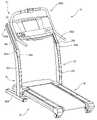
- FIG. 1is a perspective view of the self-adjusting treadmill illustrating the configuration of the console.
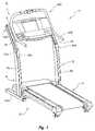
- FIG. 2Ais a side view of the self-adjusting treadmill with the console positioned at a lower height corresponding with the height of the user exercising on the self-adjusting treadmill.
- FIG. 2Bis a side view of the self-adjusting treadmill illustrating the console at a higher position corresponding with the height of the user exercising on the self-adjusting treadmill.
- FIG. 3is a perspective view of the console of the self-adjusting treadmill illustrating components of the console including the height sensor.
- FIG. 4is a front view of the height sensor of the console.
- FIG. 5is a cut-away view of the console height adjustment mechanism of the console.
- FIG. 6is a flow diagram illustrating a method of utilizing a self-adjusting console.
- FIG. 7is a side view of the self-adjusting treadmill illustrating the cushioning assembly according to one aspect of the present invention.
- FIG. 8is an internal view of the tread base illustrating the cushioning assembly utilized in connection with the self-adjusting treadmill.
- FIG. 9is a bottom view of the self-adjusting treadmill illustrating the adjustment rod and cushioning adjustment motor utilized to control adjustment of the cushioning assembly of the self-adjusting treadmill.
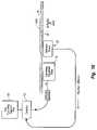
- FIG. 10is a functional block diagram illustrating a system for controlling adjustment of the cushioning assembly in connection with the self-adjusting treadmill.
- the present inventionrelates to exercise apparatuses.
- the present inventionrelates to a self-adjusting treadmill having a moveable console and a self-adjusting cushioning assembly.
- the moveable console and the self-adjusting cushioning assembly of the treadmillautomatically adjust based on user parameters.
- the user parameterscan be input by the user or automatically detected when the user is positioned on the tread base.
- the consoledetects the height of the user and is automatically raised or lowered to tailor the positioning of the console relative to the height of the user.
- the self-adjusting cushioning assemblydetects the weight of the user and automatically adjusts the amount of cushioning to accommodate the weight of the user.
- FIG. 1illustrates a treadmill 10 utilized according to one embodiment of the present invention.
- treadmill 10is a self-adjusting treadmill having one or more features which detect user parameters and which automatically adjust one or more components of the treadmill based on the sensed user parameters.
- user parametersinclude, but are not limited to, the user's weight, height, body mass index, body fat percentage, height of one or more body features, heart rate, and the like.
- a variety of types of user parameterscan be utilized in a variety of manners without departing from the scope and spirit of the present invention.
- the height of the usercan be utilized to set the height of a console of the treadmill.
- the weight of the useris utilized to set the amount of the cushioning of the treadmill.
- treadmill 10comprises a frame 20 , a console 30 , a drive motor assembly 40 , and a tread base 50 .
- Frame 20is coupled to other components of treadmill 10 .
- Frame 20provides stability to treadmill 10 when a user is exercising thereon. Additionally, frame 20 provides a mechanism to secure the components of treadmill 10 and to provide the desired configuration of treadmill 10 .
- Console 30is coupled to an upper portion of frame 20 .
- Console 30provides a user interface which allows a user to view information regarding an exercise routine being performed, select different exercise program variables, view parameters of the treadmill, and any of a variety of other features that can enhance the user's overall workout experience.
- Console 30can include control circuitry to regulate operation of other components of the treadmill.
- Drive motor assembly 40is coupled to a bottom portion of frame 20 .
- Drive motor assembly 40is positioned toward the front of treadmill 10 .
- Drive motor assembly 40facilitates movement of an endless belt and inclining of tread base 50 . Movement of the endless belt allows a user to run on the otherwise stationary tread base 50 . As the user exercises on the endless belt, inclining of tread base 50 can simulate natural changes in the slope of the running surface that are encountered during a typical outdoor exercise routine.
- Tread base 50provides a surface allowing a user to exercise on treadmill 10 .
- Tread base 50provides a desired amount of cushioning to the user exercising thereon.
- Tread base 50is coupled to frame 20 and drive motor assembly 40 .
- Frame 20provides stability and support to other components of treadmill 10 .
- Frame 20comprises a base 22 , upright frame members 24 a, b , and console support members 26 a, b .
- Base 22is positioned at the bottom of frame 20 .
- Base 22is configured to be in contact with the floor or other surface on which treadmill 10 is positioned.
- Upright frame members 24 a, bare coupled to base 22 and console support members 26 a, b .
- Upright frame members 24 a, bsupport console support members 26 a, b while providing a desired degree of displacement between base 22 and console support members 26 a, b .
- upright frame members 24 a, bare fixedly connected to base 22 to provide a rigid and constant configuration of frame 20 .
- Console support members 26 a, bare coupled to the upper ends of upright frame members 24 a, b .
- Console support members 26 a, bare also coupled to console 30 .
- the coupling between console support members 26 a, b and console 30permits console 30 to move relative to console support members 26 a, b .
- console support members 26 a, bare positioned at an angle relative to upright frame members 24 a, b .
- the angle at which console support members 26 a, b are positioned relative to upright frame members 24 a, ballow the height of console 30 to be adjusted while also changing how close console 30 is positioned relative to the user.
- a cross member 28is connected to the upper ends of console support members 26 a, b .
- Cross member 28maintains a desired displacement between console support members 26 a, b while also maintaining the overall configuration of frame 20 .
- console support membersare immovably coupled relative to console.
- the console support membersare configured to move relative to other components of the frame to change the height of the console.
- a single console support memberis positioned such that the console can move relative to the single console support member.
- the consolemoves relative to the frame without the use of console support members.
- console 30is configured to be moveable relative to at least one other component of treadmill 10 .
- console 30moves relative to both frame 20 and tread base 50 .
- Console 30is movably coupled to console support members 26 a, b such that console 30 moves relative to console support members 26 a, b when the height of console 30 is being adjusted.
- the height of console 30is automatically adjusted when the user stands on tread base 50 .
- console 30automatically detects the height of the user and adjusts the height of console 30 to tailor the height of console 30 to the user.
- the consolechanges position based on the speed that the endless belt is moving about the tread base.
- the consolechanges position based on the proximity of the user to the console.
- the consolecan move forward and backward in addition to up and down.
- FIG. 2Ais a side perspective view of treadmill 10 illustrating a user exercising on treadmill 10 .
- the configuration of drive motor assembly 40 and tread base 50 relative to frame 20is illustrated.
- Console 30is coupled to console support members 26 a, b .
- Console 30is illustrated at a position near the lower end of console support members 26 a, b .
- console 30is positioned at or near its lowest height setting.
- a height sensor 36 of console 30is positioned on the upper extremity of console 30 . Height sensor 36 directs a signal, such as a light source, infrared source, laser or other means of detecting the height of the user, in the direction of the user.
- the infrared lightemanates from height sensor 36 and then monitors for reflection of the infrared light off a surface such as the user's head or torso.
- Sensor 36detects the height of the user by monitoring a transition from the presence of reflected light to the absence of reflected light or vice versa. Once the height of the user is detected movement of console 30 is stopped, thus setting the height of console 30 at a height tailored to the height of the user. In the illustrated embodiment, the user has a relatively short height and thus console 30 is positioned at or near its lowest position.
- the height of console 30is adjusted from a default position at either its lowest or highest position. For example, where the default height of console 30 is at the highest position, the console 30 moves from its highest position downwards until the height of the user is sensed and the corresponding desired console height is achieved. Where the default height of the console is its highest position, the console does not move if reflected light is sensed. Movement of the console 30 only begins when height sensor 36 detects an absence of reflected infrared light. As the console 30 moves downwards relative to console support members 26 a, b an infrared light beam emanates from height sensor 36 and the sensor monitors for reflection of the infrared light beam. As console 30 moves in the downward direction, the infrared light beam intersects the head of the user.
- the infrared light beamintersects the head of the user, the infrared light reflects from the head of the user and is detected by the infrared sensor of height sensor 36 . Once the reflected light is detected, movement of the console 30 is stopped setting the height of console 30 . This tailors the height of console 30 relative to the user allowing simple and advantageous manipulation of the controls on console 30 . This also allows the user to view the screens and/or monitors utilized in connection with console 30 at an optimal height. Additionally, positioning of console 30 tailors the height of handrail assembly such that the handrail can be grasped easily and at a comfortable angle by the user.
- FIG. 2Bis a side perspective view of treadmill 10 illustrating operation of console 30 .
- a useris excising on treadmill 10 .
- the useris positioned on tread base 50 .
- the user exercising on treadmill 10is substantially taller than the user depicted in FIG. 2A .
- Height sensor 36 of console 30detects the taller height of the user exercising on treadmill 10 .
- Console 30is adjusted to position console 30 at a height tailored to the height of the user.
- console 30is positioned at its highest elevation allowing the taller user to easily view the display of console 30 , adjust user settings, and or grip handrails of console 30 .
- FIG. 3is a cross-sectional view of console 30 illustrating components of console 30 including height adjustment motor 31 .
- console 30is positioned between console support members 26 a, b and below cross member 28 .
- Console 30provides a mechanism for communicating information to the user and receiving input from the user.
- console 30includes a handrail assembly 32 , a user interface 34 , a height sensor 36 , and a console height adjustment mechanism 38 .
- Handrail assembly 32 of console 30is positioned on lateral sides of console 30 .
- Handrail assembly 32provides a mechanism allowing a user to grasp console 30 to provide stability and support to the user.
- movement of console 30results in adjustment of the elevation of the handrail assembly 32 .
- the elevation of handrail assembly 32is also adjusted to tailor the elevation of handrail assembly 32 to facilitate comfortable gripping by the user of the handrail assembly 32 .
- the handrail assembly 32is adjustable independently from the console.
- the handrail assemblyis directly connected to the frame of the treadmill.
- a different mechanism for allowing a user to grip the treadmill and to provide stability and support to the useris provided.
- User interface 34is positioned on the front of console 30 to facilitate interactivity between treadmill 10 and the user.
- the user interfaceincludes a display and a plurality of buttons.
- the displayprovides a mechanism for communicating information, data, exercise program information, user physiological information, or any of a variety of other types and combinations of information to the user.
- the buttonsallow the user to select different exercise program routines, different display screens, speeds of running, degrees of incline of the tread base 50 , and a variety of other types and parameters of the treadmill to provide the desired interactivity and tailoring of the treadmill to the specifications desired by the user.
- a variety of types and configurations of user interfacescan be utilized in connection with console 30 without departing from the scope or spirit of the present invention.
- a plurality of user displaysare positioned on console 30 .
- no interactive displayis utilized.
- Height sensor 36is coupled to handrail assembly 32 at the top of console 30 .
- Height sensor 36senses the height of the user positioned on tread base 50 .
- the height sensorcan detect the height of the user independent of movement of console.
- the height sensordetects the height of the user as the console moves from top to bottom or bottom to top.
- the height sensoris positioned on the frame of the treadmill.
- the height sensoris positioned at a location on the console other than the top of the handrail assembly.
- Console height adjustment mechanism 38moves the console to tailor the height of the console to the height of the user standing on the tread base 50 .
- console height adjustment mechanism 38comprises a gear 380 , a height adjustment motor 382 , a drive shaft 383 , and a bracket 385 .
- Gear 380engages console support members 26 a, b to move console 30 relative to frame 20 and tread base 50 .
- Height adjustment motor 382provides the force to cause movement of gear 380 and the consequent raising and/or lowering of console 30 .
- the consolecan be manually adjusted.
- the consolecomprises a motorized console assembly that is automatically adjustable.
- the consolecan be adjusted based on personalized setting selected relative to, or by, a user.
- Height adjustment motor 382provides the force necessary to generate the rotational movement of drive shaft 383 .
- Drive shaft 383conveys the force provided by height adjustment motor 382 to gear 380 .
- the lower end of console support member 26 ais illustrated with endcap member 264 a being removed.
- the grooves in console support member 26 aare adapted to accommodate a portion of console height adjustment mechanism 38 .
- An illustrative console height adjustment mechanismwill be illustrated in greater detail with reference to FIG. 5 .
- FIG. 4illustrates a height sensor 36 according to one embodiment of the present invention.
- height sensor 36is coupled to a cross portion of handrail assembly 32 .
- height sensor 36includes a handrail sensor mechanism 360 and status Light Emitting Diodes (leds) 366 a - e .
- Sensor mechanism 360detects the height of a user positioned on tread base 50 of treadmill 10 .
- Sensor mechanism 360includes a light source 362 and a light detector 364 .
- Light source 362provides the light that is utilized to detect the height of the user. Light emanating from light source 362 can reflect from the user when the light contacts the user. When light reflects from the user, it is detected by light detector 364 . In this manner, sensor mechanism 360 can detect whether a user is positioned in front of height sensor 36 .
- height sensor 36utilizes movement of console 30 to detect the height of the user. For example, where the console starts at a default position at its upper-most height, light emanates from light source 362 . Light detector 364 is actuated to determine whether light from light source 362 is reflecting from the user. If no reflected light is detected, console 30 moves downward in the direction of the lower end 262 a, b of console support members 26 a, b . As console 30 moves downward, light source 362 intersects the point at which the user's head is contacted by light emanating from light source 362 . As the light emanating from light source 362 contacts the user's head it is reflected such that it can be detected by light detector 364 . At this point, the height of the user is ascertained and the height of the console is set accordingly.
- console 30stops its downward progression.
- the angle of the light emanating from light source 362is set such that the light will contact and reflect from the user when console 30 is at the desired height for the user.
- the height of the consoleis set at a level tailored to the height of the user positioned on tread base 50 .
- light source 362utilizes an infrared beam to detect the height of the user.
- light emanating from the light sourceis directed at an upward angle such that the console is positioned at a desirable elevation relative to the overall height of the user.
- a laser or other light sourceis utilized in connection with the sensor mechanism.
- the consolestarts at a default position in which the console is at its lowest height and moves upward to detect the height of the user.
- status leds 366 a - eare positioned on the upper portion of height sensor 36 .
- Status leds 366 a - eprovide a visual indication of operability of height sensor 36 .
- status leds 366 a - ecan provide an indication by flashing alternatively, consecutively, iteratively or in any other type or combination to indicate operability of height sensor 36 .
- when height sensor 36 is attempting to identify the height of the userstatus leds 366 a - e flash to indicate that a determination of the user's height is in progress.
- one or more of the status leds 366 a - eare actuated as an indicator of the height detected and thus the height of console 30 .
- a variety of types and other configurations of status ledscan be utilized in a variety of manners without departing from the scope and spirit of the present invention.
- FIG. 5is a cut-away side view of console support member 26 a illustrating console height adjustment mechanism 38 of console 30 .
- the lower end 262 a of console support member 26 ais illustrated.
- Lower end 262 a of console support member 26 aincludes a gear slot 270 , a rack 272 , an upper guide portion 274 , and a lower guide portion 276 .
- the components of console support member 26 ainteract with console height adjustment mechanism 38 to allow for movement of console 30 .
- Console height adjustment mechanism 38includes a gear 380 and a height adjustment motor 382 (see FIG. 3 ).
- Gear 380engages rack 272 of console support member 26 a .
- As gear 380 is rotated by height adjustment motor 382 movement of gear 380results in repositioning of console 380 as the teeth of gear 380 engage rack 272 .
- Gear 380is positioned in gear slot 270 .
- the size and width of gear slot 270accommodates gear 380 to allow for movement of gear 380 along the length of rack 272 .
- Upper guide portion 274 and lower guide portion 276engage a flange of console 30 .
- the flange, in combination with upper guide portions 274 and lower guide portion 276ensures smooth and efficient movement of console 30 while preventing lateral movement along the length of console 30 .
- the console height adjustment mechanismutilizes a lead screw to adjust to the height of the console.
- the consoleis moved by moving the console support members.
- FIG. 6is a flow diagram illustrating a method for adjusting the height of a console based on the height of the user positioned on the treadmill.
- the methodis started in step 102 . It is than ascertained whether a user is positioned on the treadmill in step 104 . Once it is determined that a user is positioned on the treadmill, downward movement of the console is started from a default position at the console's uppermost position in step 106 . Once downward movement of the console is started, a sensing signal is emitted from the sensor in step 108 .
- the sensing signalcan comprise a infrared light source, a laser, or other signal utilized to detect the height of the user.
- step 110the presence or absence of a reflected signal is detected in step 110 . It is then determined if a reflective signal has been detected in step 112 . If no reflected signal has been detected then the method returns to step 108 and a sensing signal is again emitted from the sensor. If a reflected signal has been detected then downward movement of the console is stopped in step 114 . Once the lowering of the treadmill console has been stopped, the height of the user has been ascertained and the console has tailored to the height of the user and the method is ended in step 116 .
- additional actsare utilized to readjust the treadmill every time the user changes the degree of inclination of the tread base.
- detection of the height of the userdoes not start from a default position.
- the consolestarts with upward movement where a reflected signal is detected or starts with downward movement where no reflected signal is detected. The height of the user is determined where the sensor detects a transition from a reflected signal to a non-reflected signal and vice versa.
- FIG. 7is a side perspective view of treadmill 10 illustrating a cushioning assembly 60 according to one aspect of the present invention.
- Cushioning assembly 60is utilized in connection with tread base 50 .
- Tread base 50provides a surface allowing a user to exercise on treadmill 10 .
- Tread base 50is coupled to frame 20 and drive motor assembly 40 .
- Tread base 50includes a proximal end 52 , a distal end 54 , an endless belt 55 , a deck 56 , and a tread base frame 58 .
- Proximal end 52 of tread base 50is positioned adjacent to drive motor assembly 40 .
- Distal end 54is positioned away from drive motor assembly 40 .
- Endless belt 55is trained around deck 56 .
- Endless belt 55provides a continuous running surface simulating movement of a road base or other ambulatory surface on which a user ambulates during exercise on treadmill 10 .
- Deck 56provides support below endless belt 55 to withstand impact from a user exercising thereon. According to one embodiment of the present invention, deck 56 flexes during impact to provide cushioning to a user exercising on tread base 50 .
- Tread base frame 58provides a support structure upon which other components of tread base 50 are coupled.
- Cushioning assembly 60is coupled to tread base 50 .
- Cushioning assembly 60provides cushioning to control the amount of deflection of deck 56 with respect to tread base frame 58 .
- cushioning assembly 60automatically adjusts the amount of cushioning experienced by the user on deck 56 .
- the amount of cushioning providedcan be varied based on the weight, desired amount of deflection of the deck, or other parameters that can be utilized to customize the amount of cushioning provided by cushioning assembly to a user exercising on tread base 50 .
- cushioning assembly 60comprises a variable cushioning mechanism 70 and a deflection sensor assembly 80 .
- Variable cushioning mechanism 70provides a mechanism for providing variable amounts of cushioning to a user exercising on tread base 50 .
- Deflection sensor assembly 80provides a mechanism for monitoring user parameters, such as the weight of the user or body mass index of the user, to automatically adjust the amount of cushioning provided by cushioning assembly 60 .
- variable cushioning mechanism 70includes a cushioning member 72 .
- Cushioning member 72is coupled to a portion of tread base frame 58 .
- Cushioning member 72is comprised of a resilient material that is utilized to absorb impact on deck 56 .
- Cushioning member 72contacts deck 56 such that when a user is exercising on deck 56 cushioning member 72 absorbs impact while also controlling the amount of deflection of deck 56 .
- Variable cushioning mechanism 70is one example of an adjustment mechanism. Variable cushioning mechanism 70 will be discussed in greater detail with reference to FIG. 8 .
- the adjustment mechanismis selected from one of the group consisting of a rheologic mechanism, an airbag, a spring, an air shock, a hydraulic cylinder, a hydraulic bellow, a leaf spring, a coil spring, a solid hollow elastomeric member, a bellows, a cylinder, and a gas shock.
- deflection sensor assembly 80includes a sensor mechanism 82 and a deflection member 84 .
- Deflection member 84is coupled to deck 56 such that deflection of deck 56 result in movement of deflection member 84 .
- Sensor mechanism 82is coupled to tread base frame 58 .
- Sensor mechanism 82detects movement of deflection member 84 and monitors the amount of movement of deflection member 84 . Based on the amount of movement of deflection member 84 sensor mechanism is able to ascertain the amount of deflection of deck 56 .
- the deflection of the deckcan be utilized in a variety of manners without departing from the scope and spirit of the present invention.
- the amount of deflection of the deckcan be utilized to determine if the user can safely use the treadmill.
- a small amount of deflectioncan allow the system to determine if a child is positioned on the treadmill. Based on the determination, the system can prevent movement of the endless belt.
- the amount of deflection of deckcan be used to ascertain the weight of the user standing on deck.
- the amount of deflection of deckis used to maintain desired amounts of cushioning for users of different weights.
- the amount of cushioningis set at a pre-adjustment setting when the user first steps on the tread base and is then adjusted as the user begins to exercise.
- Utilizing the pre-adjustment settingallows the system to approximate the cushioning setting that will provide the desired amount of cushioning during exercise.
- the amount of cushioningcan be controlled to maintain a desired amount of deflection of the deck.
- the following numerical descriptionprovides an example of how a pre-adjustment setting can be utilized.
- the amount of cushioningis adjusted to maintain the displacement of the deck between 0.5 inches and 0.75 inches. When a heavy user steps on the deck resulting in displacement of more than 0.75 inches, the amount of cushioning is decreased until the displacement is less than 0.75 inches. When a light user steps on the deck resulting in displacement of less than 0.5 inches, the amount of cushioning is increased until the displacement is greater than 0.5 inches.
- the amount of cushioningis adjusted if the displacement of the treadmill is not between the target displacement of 0.75 inches and 1.0 inches.
- the amount of displacement experienced when exercise is startedwill be approximately between the target of 0.75 inches and 1.0 inches.
- Deflection sensor assemblycan be utilized in a variety of manners to sense parameters regarding the user. For example, the body mass index of the user can be determined using the height and automatically sensed weight of the user. In another embodiment, indicia are utilized to illustrate a point on tread base on which the user is to stand to accurately sense the height and weight of the user. Deflection sensor assembly will be discussed in greater detail with reference to FIG. 8 .
- the cushioning assembly of the present inventioncan be utilized with a variety of types and configurations of treadmills. For example, the cushioning assembly can be utilized with a treadmill in which the deck does not flex to absorb impact of the user exercising thereon.
- FIG. 8is a close up side view of cushioning assembly 60 illustrating variable cushioning mechanism 70 and deflection sensor assembly 80 .
- variable cushioning mechanism 70is coupled to tread base frame 58 such that cushioning member 72 contacts deck 56 .
- Variable cushioning mechanism 70includes cushioning member 72 , lever arm 74 , and moveable fulcrum 76 .
- cushioning member 72is adapted to contact deck 56 so as to absorb impact from a user exercising on tread base 50 .
- Cushioning member 72is coupled to lever arm 74 .
- Lever arm 74provides a variable amount of resistance based on the effective length of the lever as determined by the position of movable fulcrum 76 along the length of lever arm 74 .
- Lever arm 74is coupled to a cross member of tread base frame 58 .
- Moveable fulcrum 76is positioned beneath lever arm 74 between cushioning member 72 and the point of coupling with cross member 59 .
- cushioning member 72absorbs energy from the deflection of deck 56 .
- Lever arm 74can flex and thus absorb some of the energy from the deflection of deck 56 .
- Moveable fulcrum 76can be moved closer to, and away from, cushioning member 72 .
- the effective length of lever arm 74 and the amount of flexing of lever arm 74varies based on the position of moveable fulcrum 76 .
- cushioning member 72lever arm 74 flexes less than when movable fulcrum is positioned nearer to point of coupling 59 .
- the smaller amount of flex of lever arm 74results in a smaller amount of deflection of deck 56 .
- the userexperiences less cushioning and a stiffer deck during exercise on tread base 50 .
- greater leveragecan be exerted on lever arm 74 resulting in a greater displacement of deck 56 and flexing of lever arm 74 .
- the userexperiences more cushioning and a softer deck when a user is exercising on tread base.
- Deflection sensor assembly 80allows cushioning assembly 60 to automatically adjust the position of moveable fulcrum 76 to provide a desired amount of cushioning from variable cushioning mechanism 70 . Because deflection of the deck is based in part on the weight of the person exercising on deck 56 moveable fulcrum 76 can be repositioned to maintain a desired amount of cushioning when a user of a different weight begins to exercise on deck 56 . For example, if an intermediate amount of cushioning is selected, moveable fulcrum 76 will be moved toward cushioning member 72 when a relatively light weight user is replaced by a heavier user.
- deflection sensor assembly 80is configured to sense differences in the weight of a new user positioned on deck 56 to automatically make adjustments to variable cushioning mechanism 70 to maintain a desired level of cushioning.
- deflection member 84is coupled to deck 56 of tread base 50 . When a user is positioned on tread base 50 , deck 56 deflects in a downward direction. Such deflection is sensed by sensor mechanism 82 . The amount of movement of deflection member 84 is monitored and the weight of the user positioned on tread base 50 is ascertained. Based on the known weight of the user, moveable fulcrum 76 can be repositioned to maintain the desired degree of cushioning provided by variable cushioning mechanism 70 .
- variable cushioning mechanism 70is given a pre-adjustment setting based on a coarse weight reading of the user when the user first is positioned on the deck. Once the user begins to exercise, the variable cushioning mechanism 70 undergoes additional adjustment to fine tune the amount of cushioning subsequent to the coarse weight reading. By providing a pre-adjustment setting based on a coarse weight reading, the variable cushioning mechanism 70 can more closely approximate the desired amount of cushioning before the user starts exercising. Thus, even before the exact weight or desired setting of the variable cushioning mechanism is ascertained, a rough estimation of the setting of the variable cushioning mechanism is provided.
- a variety of coarse weight categoriesare determined with a pre-adjustment setting for the variable cushioning mechanism being associated with each coarse weight category. When the user steps on the deck 56 , the coarse weight reading of the user is ascertained, associated with a weight category, and then the variable cushioning mechanism is automatically adjusted to the pre-adjustment setting associated with coarse weight category.
- the deflection sensor assemblycomprises a hall effect sensor.
- the deflection sensoris from a group comprising an optical sensor, a magnetic sensor, a potentiometer, a linear potentiometer, or a rotary potentiometer, a contact sensor, a contact sensing device.
- the sensordetects the weight of the user without sensing deflection of the deck.
- deflection sensor assembly 80 and variable cushioning mechanisms 70can be utilized to provide additional functionality other than maintaining a desired degree of cushioning relative to users of different weights”
- a user of a constant weightmay desire a change in the amount of cushioning provided by variable cushioning mechanism 70 based on the type or intensity of exercise to be performed. For example, a user may select a large amount of cushioning for a long and slow paced workout while desiring a small amount of cushioning for a shorter more intense workout.
- moveable fulcrum 76can be repositioned along the length of lever arm 74 to accommodate such changes in the desired amount of cushioning.
- deflection of deck 56can be a function of the amount of force exerted by the user on deck 56 during an exercise routine.
- a user having a constant weightwill exert a given amount of pressure on deck 56 when walking and relatively greater amount of pressure on deck 56 , resulting in a larger deflection of deck 56 , when running at full speed.
- Such changes in deflectioncan be monitored by deflection sensor assembly 80 .
- moveable fulcrum 76can be moved along the length of lever arm 74 to maintain a desired degree of cushioning during an exercise routine in which the force exerted by the user on deck 56 changes during the routine.
- FIG. 9illustrates a bottom perspective view of treadmill 10 illustrating components of cushioning assembly 60 according to one aspect of the present invention.
- variable cushioning mechanism 70includes cushioning members 72 a, b , lever arms 74 a, b , moveable fulcrums 76 a, b and a transverse bar 78 .
- Cushioning members 76 a, bare positioned on each side of deck 56 to provide a bilateral and predetermined amount of cushioning on deck 56 .
- lever arms 74 a, b and moveable fulcrums 76 a, bare positioned on either side of deck 56 to provide the desired level of cushioning on deck 56 .
- Transverse bar 78is positioned between moveable fulcrum 76 a, b .
- Transverse bar 78facilitates uniform movement of moveable fulcrum 76 a, b to maintain an equal amount of displacement of moveable fulcrums 76 a, b .
- a consistent amount of cushioningis provided by lever arms 74 a, b and cushioning members 72 a, b .
- Transverse bar 78is coupled to adjustment rod 90 .
- Adjustment rod 90is coupled to cushioning adjustment motor 92 .
- Cushioning adjustment motor 92causes lengthening and shortening of adjustment rod 90 .
- movement of transverse bar 78occurs proximally and distally along the length of moveable fulcrum 76 a, b .
- Movement of transverse bar 78results in movement of moveable fulcrum 76 a, b and a change in the amount of cushioning provided by variable cushioning mechanism 70 .
- a variety of types and configurations of cushioning assembly 60can be used without departing from the scope and spirit of the present invention.
- a lead screw assemblyis utilized to cause movement of the moveable fulcrum.
- a single cushioning memberis positioned across the entire lateral length of the deck.
- a plurality of variable cushioning mechanismsare positioned along the length of tread base.
- a cushioning assemblyis adapted to provide a variable amount of cushioning with a treadmill in which the cushioning is provided by mechanisms other than the treadmill deck.
- FIG. 10is a block diagram view illustrating operation of cushioning assembly 60 according to one aspect of the present invention.
- deflection sensor assembly 80detects deflection of deck 56 and conveys the amount of deflection to controller 101 .
- Controller 101ascertains the weight of the user based on the reported deflection and known properties of deck 56 .
- the userinputs the desired amount of cushioning to be provided by the variable cushioning mechanism 70 by inputting the desired amount of cushioning into user cushioning selection pad 100 .
- user cushioning selection pad 100is provided in the user interface of console 30 .
- controller 101Based on the weight of the user and information regarding the desired amount of cushioning input into user cushioning selection pad 100 , controller 101 sends cushioning instructions to cushioning adjustment motor 92 of variable cushioning mechanism 70 .
- the cushioning adjustment motor 92causes movement of moveable fulcrum 76 a, b to change the amount of cushioning to the desired amount of cushioning.
- cushioning assembly 60automatically detects the weight of the user and adjusts the amount of cushioning provided by variable cushioning mechanism 70 such that the amount of cushioning provided is appropriate based on the desired amount of cushioning selected by the user.
- the controllercomprises an input mechanism that allows the user to input a desired amount of cushioning.
- the desired amount of cushioningis selected from a group consisting of hard, medium or soft cushioning.
- the desired amount of cushioningcan be selected from a continuum of amounts of cushioning.
- any changes in deflection of deck 56are sensed by deflection sensor 80 , and conveyed back to controller 101 .
- Such changes in deflection of deck 56can be caused by an increased impact force related to the intensity of the user's workout; changes in the weight of the user subsequent to a change in user; or other factors such as the use of weights added during the exercise routine.
- any changes in the desired amount of cushioning to be provided by variable cushioning mechanism 70can be monitored by controller 101 .
- any combination of changes in reported deflection and desired amount of cushioning input by usercan result in new cushioning instructions to variable cushioning mechanism 70 .
- Such instructionscan result in change of the position of moveable fulcrums 76 a, b to change the amount of cushioning provided by lever arm 74 and cushioning member 72 .
- the controllercan be automatically set to change the amount of cushioning based on the amount of deflection of deck.
- the deflection sensor and controllercan be integrally coupled into a single unit.
- the deflection sensoris actuated only in response to user input on the user cushioning selection pad. Any variety of combinations of cushioning assemblies and moveable consoles can be utilized without departing from the scope and spirit of the present invention.
- the disclosure of patent application entitled, “Cushioning Treadmill”, filed Jan. 9, 2004 of Express Mail Number EV 396 740 446 US,is hereby incorporated by reference in its entirety.
Landscapes
- Health & Medical Sciences (AREA)
- Cardiology (AREA)
- Vascular Medicine (AREA)
- General Health & Medical Sciences (AREA)
- Physical Education & Sports Medicine (AREA)
- Rehabilitation Tools (AREA)
Abstract
Description
Claims (37)
Priority Applications (1)
| Application Number | Priority Date | Filing Date | Title |
|---|---|---|---|
| US10/754,166US7344481B2 (en) | 2004-01-09 | 2004-01-09 | Treadmill with moveable console |
Applications Claiming Priority (1)
| Application Number | Priority Date | Filing Date | Title |
|---|---|---|---|
| US10/754,166US7344481B2 (en) | 2004-01-09 | 2004-01-09 | Treadmill with moveable console |
Publications (2)
| Publication Number | Publication Date |
|---|---|
| US20050164838A1 US20050164838A1 (en) | 2005-07-28 |
| US7344481B2true US7344481B2 (en) | 2008-03-18 |
Family
ID=34794719
Family Applications (1)
| Application Number | Title | Priority Date | Filing Date |
|---|---|---|---|
| US10/754,166Active2025-10-21US7344481B2 (en) | 2004-01-09 | 2004-01-09 | Treadmill with moveable console |
Country Status (1)
| Country | Link |
|---|---|
| US (1) | US7344481B2 (en) |
Cited By (65)
| Publication number | Priority date | Publication date | Assignee | Title |
|---|---|---|---|---|
| US20070225120A1 (en)* | 2006-03-27 | 2007-09-27 | Peter Schenk | Zero-learning-curve exercise console |
| US20080312047A1 (en)* | 2007-06-18 | 2008-12-18 | Johnson Health Tech Co., Ltd | Treadmill |
| US20120032896A1 (en)* | 2010-08-06 | 2012-02-09 | Jan Vesely | Self-service terminal and configurable screen therefor |
| US8435160B1 (en)* | 2011-02-07 | 2013-05-07 | Gerald M. Clum | Shock-absorbing treadmill |
| USD704778S1 (en)* | 2013-01-11 | 2014-05-13 | Ds-Design | Treadmill |
| US20150192929A1 (en)* | 2011-12-06 | 2015-07-09 | Microsoft Technology Licensing, Llc | Electronic compensated pivot control |
| US9764184B2 (en) | 2014-12-19 | 2017-09-19 | True Fitness Technology, Inc. | High-incline treadmill |
| US20180099179A1 (en)* | 2016-10-12 | 2018-04-12 | Icon Health & Fitness, Inc. | Linear Bearing for Console Positioning |
| US20180117419A1 (en)* | 2016-11-01 | 2018-05-03 | Icon Health & Fitness, Inc. | Distance Sensor for Console Positioning |
| US10188890B2 (en) | 2013-12-26 | 2019-01-29 | Icon Health & Fitness, Inc. | Magnetic resistance mechanism in a cable machine |
| US10252109B2 (en) | 2016-05-13 | 2019-04-09 | Icon Health & Fitness, Inc. | Weight platform treadmill |
| US10258828B2 (en) | 2015-01-16 | 2019-04-16 | Icon Health & Fitness, Inc. | Controls for an exercise device |
| US10272317B2 (en) | 2016-03-18 | 2019-04-30 | Icon Health & Fitness, Inc. | Lighted pace feature in a treadmill |
| US10279212B2 (en) | 2013-03-14 | 2019-05-07 | Icon Health & Fitness, Inc. | Strength training apparatus with flywheel and related methods |
| US10293211B2 (en) | 2016-03-18 | 2019-05-21 | Icon Health & Fitness, Inc. | Coordinated weight selection |
| US10335632B2 (en) | 2015-12-31 | 2019-07-02 | Nautilus, Inc. | Treadmill including a deck locking mechanism |
| US10376736B2 (en) | 2016-10-12 | 2019-08-13 | Icon Health & Fitness, Inc. | Cooling an exercise device during a dive motor runway condition |
| US10398932B2 (en) | 2015-12-31 | 2019-09-03 | Nautilus, Inc. | Treadmill including a lift assistance mechanism |
| US10426989B2 (en) | 2014-06-09 | 2019-10-01 | Icon Health & Fitness, Inc. | Cable system incorporated into a treadmill |
| US10433612B2 (en) | 2014-03-10 | 2019-10-08 | Icon Health & Fitness, Inc. | Pressure sensor to quantify work |
| US10441840B2 (en) | 2016-03-18 | 2019-10-15 | Icon Health & Fitness, Inc. | Collapsible strength exercise machine |
| US10441844B2 (en) | 2016-07-01 | 2019-10-15 | Icon Health & Fitness, Inc. | Cooling systems and methods for exercise equipment |
| US10449416B2 (en) | 2015-08-26 | 2019-10-22 | Icon Health & Fitness, Inc. | Strength exercise mechanisms |
| US10471299B2 (en) | 2016-07-01 | 2019-11-12 | Icon Health & Fitness, Inc. | Systems and methods for cooling internal exercise equipment components |
| US10493349B2 (en) | 2016-03-18 | 2019-12-03 | Icon Health & Fitness, Inc. | Display on exercise device |
| US10500473B2 (en) | 2016-10-10 | 2019-12-10 | Icon Health & Fitness, Inc. | Console positioning |
| US10543395B2 (en) | 2016-12-05 | 2020-01-28 | Icon Health & Fitness, Inc. | Offsetting treadmill deck weight during operation |
| US10561894B2 (en) | 2016-03-18 | 2020-02-18 | Icon Health & Fitness, Inc. | Treadmill with removable supports |
| US10625137B2 (en) | 2016-03-18 | 2020-04-21 | Icon Health & Fitness, Inc. | Coordinated displays in an exercise device |
| US10661114B2 (en) | 2016-11-01 | 2020-05-26 | Icon Health & Fitness, Inc. | Body weight lift mechanism on treadmill |
| US10661119B2 (en) | 2018-04-30 | 2020-05-26 | James P. Bradley | Autonomous safety system for a treadmill |
| US10729965B2 (en) | 2017-12-22 | 2020-08-04 | Icon Health & Fitness, Inc. | Audible belt guide in a treadmill |
| US10786706B2 (en) | 2018-07-13 | 2020-09-29 | Icon Health & Fitness, Inc. | Cycling shoe power sensors |
| US10918905B2 (en) | 2016-10-12 | 2021-02-16 | Icon Health & Fitness, Inc. | Systems and methods for reducing runaway resistance on an exercise device |
| US10940360B2 (en) | 2015-08-26 | 2021-03-09 | Icon Health & Fitness, Inc. | Strength exercise mechanisms |
| US10953305B2 (en) | 2015-08-26 | 2021-03-23 | Icon Health & Fitness, Inc. | Strength exercise mechanisms |
| US11000730B2 (en) | 2018-03-16 | 2021-05-11 | Icon Health & Fitness, Inc. | Elliptical exercise machine |
| US11033777B1 (en) | 2019-02-12 | 2021-06-15 | Icon Health & Fitness, Inc. | Stationary exercise machine |
| US11058914B2 (en) | 2016-07-01 | 2021-07-13 | Icon Health & Fitness, Inc. | Cooling methods for exercise equipment |
| US11058913B2 (en) | 2017-12-22 | 2021-07-13 | Icon Health & Fitness, Inc. | Inclinable exercise machine |
| US11187285B2 (en) | 2017-12-09 | 2021-11-30 | Icon Health & Fitness, Inc. | Systems and methods for selectively rotationally fixing a pedaled drivetrain |
| US11244751B2 (en) | 2012-10-19 | 2022-02-08 | Finish Time Holdings, Llc | Method and device for providing a person with training data of an athlete as the athlete is performing a swimming workout |
| US11298577B2 (en) | 2019-02-11 | 2022-04-12 | Ifit Inc. | Cable and power rack exercise machine |
| US11326673B2 (en) | 2018-06-11 | 2022-05-10 | Ifit Inc. | Increased durability linear actuator |
| US11451108B2 (en) | 2017-08-16 | 2022-09-20 | Ifit Inc. | Systems and methods for axial impact resistance in electric motors |
| US20220362627A1 (en)* | 2021-05-17 | 2022-11-17 | Rexon Industrial Corp., Ltd. | Treadmill with anti-entrapment function |
| US20220379163A1 (en)* | 2021-05-25 | 2022-12-01 | Rexon Industrial Corp., Ltd. | Treadmill with safety monitoring function and safety monitoring method for treadmil |
| US11534654B2 (en) | 2019-01-25 | 2022-12-27 | Ifit Inc. | Systems and methods for an interactive pedaled exercise device |
| US11534651B2 (en) | 2019-08-15 | 2022-12-27 | Ifit Inc. | Adjustable dumbbell system |
| US11673036B2 (en) | 2019-11-12 | 2023-06-13 | Ifit Inc. | Exercise storage system |
| US11794070B2 (en) | 2019-05-23 | 2023-10-24 | Ifit Inc. | Systems and methods for cooling an exercise device |
| US11850497B2 (en) | 2019-10-11 | 2023-12-26 | Ifit Inc. | Modular exercise device |
| US11878199B2 (en) | 2021-02-16 | 2024-01-23 | Ifit Inc. | Safety mechanism for an adjustable dumbbell |
| US11931621B2 (en) | 2020-03-18 | 2024-03-19 | Ifit Inc. | Systems and methods for treadmill drift avoidance |
| US11951377B2 (en) | 2020-03-24 | 2024-04-09 | Ifit Inc. | Leaderboard with irregularity flags in an exercise machine system |
| US12029935B2 (en) | 2021-08-19 | 2024-07-09 | Ifit Inc. | Adjustment mechanism for an adjustable kettlebell |
| US12029961B2 (en) | 2020-03-24 | 2024-07-09 | Ifit Inc. | Flagging irregularities in user performance in an exercise machine system |
| US12176009B2 (en) | 2021-12-30 | 2024-12-24 | Ifit Inc. | Systems and methods for synchronizing workout equipment with video files |
| US12219201B2 (en) | 2021-08-05 | 2025-02-04 | Ifit Inc. | Synchronizing video workout programs across multiple devices |
| US12263371B2 (en) | 2021-04-27 | 2025-04-01 | Ifit Inc. | Devices, systems, and methods for rotating a tread belt in two directions |
| US12280294B2 (en) | 2021-10-15 | 2025-04-22 | Ifit Inc. | Magnetic clutch for a pedaled drivetrain |
| US12350573B2 (en) | 2021-04-27 | 2025-07-08 | Ifit Inc. | Systems and methods for cross-training on exercise devices |
| US12350547B2 (en) | 2022-02-28 | 2025-07-08 | Ifit Inc. | Devices, systems, and methods for moving a movable step through a transition zone |
| US12409375B2 (en) | 2022-03-18 | 2025-09-09 | Ifit Inc. | Systems and methods for haptic simulation in incline exercise devices |
| US12433815B2 (en) | 2020-10-02 | 2025-10-07 | Ifit Inc. | Massage roller with pressure sensors |
Families Citing this family (18)
| Publication number | Priority date | Publication date | Assignee | Title |
|---|---|---|---|---|
| US7771319B1 (en)* | 2004-05-10 | 2010-08-10 | Michael G. Lannon | Exercising apparatus |
| ITBO20060534A1 (en)* | 2006-07-11 | 2008-01-12 | Technogym Spa | GINNICA MACHINE. |
| US8082029B2 (en)* | 2007-05-17 | 2011-12-20 | Brunswick Corporation | Adjustable sensors for use with exercise apparatus |
| US9339691B2 (en) | 2012-01-05 | 2016-05-17 | Icon Health & Fitness, Inc. | System and method for controlling an exercise device |
| US20130190136A1 (en)* | 2012-01-09 | 2013-07-25 | Icon Health & Fitness, Inc. | Exercise Device With Adjustable Console |
| US8764609B1 (en) | 2012-05-20 | 2014-07-01 | Issam A. Elahmadie | Exercise enhancement machine |
| CN103340735B (en)* | 2013-07-26 | 2015-11-25 | 上海市第六人民医院 | Force measurement type walking aid device |
| CN104606842B (en)* | 2013-11-04 | 2018-08-28 | 岱宇国际股份有限公司 | Plane type running machine |
| WO2015195965A1 (en) | 2014-06-20 | 2015-12-23 | Icon Health & Fitness, Inc. | Post workout massage device |
| WO2016065077A1 (en) | 2014-10-23 | 2016-04-28 | Corepact, Llc | Cordless treadmill |
| US10391361B2 (en) | 2015-02-27 | 2019-08-27 | Icon Health & Fitness, Inc. | Simulating real-world terrain on an exercise device |
| CN105999623A (en)* | 2016-07-01 | 2016-10-12 | 河南省人民医院 | Mobile panel movement testing machine capable of adjusting armrest height automatically |
| US10671705B2 (en) | 2016-09-28 | 2020-06-02 | Icon Health & Fitness, Inc. | Customizing recipe recommendations |
| CN113058209A (en)* | 2021-03-23 | 2021-07-02 | 泊康科技股份有限公司 | Running board hardness self-adjusting method applied to running board and application |
| CN113018767A (en)* | 2021-03-23 | 2021-06-25 | 泊康科技股份有限公司 | Running board capable of acquiring sinking amplitude variation value of running board and running machine |
| CN113018766B (en)* | 2021-03-23 | 2022-04-19 | 泊康科技股份有限公司 | Running board and running machine capable of realizing self adjustment of hardness of running board |
| TWI764731B (en)* | 2021-05-25 | 2022-05-11 | 力山工業股份有限公司 | A treadmill with safety monitoring system and monitoring method thereof |
| WO2023250432A1 (en)* | 2022-06-24 | 2023-12-28 | Life Fitness, Llc | Fitness machines with adjustable shock absorption and methods of adjusting shock absorption for fitness machines |
Citations (29)
| Publication number | Priority date | Publication date | Assignee | Title |
|---|---|---|---|---|
| US4708337A (en)* | 1985-12-20 | 1987-11-24 | Industrial Technology Research Institute | Automatic treadmill |
| US4976424A (en)* | 1987-08-25 | 1990-12-11 | Schwinn Bicycle Company | Load control for exercise device |
| USD318699S (en) | 1989-02-01 | 1991-07-30 | Jacobson David L | Treadmill |
| USD323009S (en) | 1990-01-31 | 1992-01-07 | Proform Fitness Products, Inc. | Treadmill exerciser |
| USD323199S (en) | 1990-01-31 | 1992-01-14 | Proform Fitness Products, Inc. | Treadmill exerciser |
| USD323198S (en) | 1990-01-31 | 1992-01-14 | Proform Fitness Products, Inc. | Treadmill exerciser |
| US5102380A (en) | 1989-02-01 | 1992-04-07 | Proform Fitness Products, Inc. | Cooling exercise treadmill |
| US5104119A (en) | 1989-01-03 | 1992-04-14 | Lynch Robert P | Treadmill with variable upper body resistance loading |
| US5145481A (en) | 1990-07-10 | 1992-09-08 | Fitness Master, Inc. | Ski exercise machine |
| US5277678A (en)* | 1992-07-28 | 1994-01-11 | Fitness Master, Inc. | Video interactive ski exerciser |
| US5282776A (en) | 1992-09-30 | 1994-02-01 | Proform Fitness Products, Inc. | Upper body exerciser |
| USD344557S (en) | 1993-05-25 | 1994-02-22 | Proform Fitness Products, Inc. | Treadmill |
| USD348493S (en) | 1993-04-08 | 1994-07-05 | Proform Fitness Products, Inc. | Combined handle and console unit for an exercise machine |
| US5336145A (en) | 1991-08-30 | 1994-08-09 | Keiser Dennis L | Apparatus having a movable load bearing surface |
| USD351202S (en) | 1993-04-08 | 1994-10-04 | Proform Fitness Products, Inc. | Treadmill base |
| USD351633S (en) | 1993-04-08 | 1994-10-18 | Proform Fitness Products, Inc. | Combined handle and console unit for an exerciser |
| US5595556A (en) | 1992-09-30 | 1997-01-21 | Icon Health & Fitness, Inc. | Treadmill with upper body system |
| US5645509A (en) | 1991-07-02 | 1997-07-08 | Icon Health & Fitness, Inc. | Remote exercise control system |
| US5771152A (en)* | 1995-05-08 | 1998-06-23 | International Business Machines Corporation | Computer system with a tilt adjustment mechanism |
| US5860893A (en) | 1996-01-30 | 1999-01-19 | Icon Health & Fitness | Treadmill with folding handrails |
| US5890562A (en)* | 1996-08-16 | 1999-04-06 | Bt Prime Mover, Inc. | Control console for material handling vehicle |
| USD421779S (en) | 1996-11-01 | 2000-03-21 | Piaget Gary D | Treadmill-type exercise apparatus |
| US6135924A (en)* | 1997-04-11 | 2000-10-24 | Unisen, Inc. | Treadmill with optical position sensing |
| US6163451A (en)* | 1998-10-28 | 2000-12-19 | Senor Science Co., Ltd. | Display base |
| US6276749B1 (en)* | 1999-03-24 | 2001-08-21 | Komatsu Ltd. | Position adjusting apparatus of control console for work vehicle |
| US6432026B1 (en) | 2000-07-21 | 2002-08-13 | Leao Wang | Height-adjustable mechanism for a running frame of a treadmill |
| US6450284B1 (en)* | 1999-04-19 | 2002-09-17 | Hitachi Construction Machinery Co., Ltd. | Cab for construction machinery |
| US6461275B1 (en) | 2000-10-30 | 2002-10-08 | Leao Wang | Elevatingly folding unit of electric exercise treadmill |
| US6475121B2 (en) | 2001-01-16 | 2002-11-05 | Leao Wang | Elevating apparatus of an exercise treadmill |
- 2004
- 2004-01-09USUS10/754,166patent/US7344481B2/enactiveActive
Patent Citations (29)
| Publication number | Priority date | Publication date | Assignee | Title |
|---|---|---|---|---|
| US4708337A (en)* | 1985-12-20 | 1987-11-24 | Industrial Technology Research Institute | Automatic treadmill |
| US4976424A (en)* | 1987-08-25 | 1990-12-11 | Schwinn Bicycle Company | Load control for exercise device |
| US5104119A (en) | 1989-01-03 | 1992-04-14 | Lynch Robert P | Treadmill with variable upper body resistance loading |
| US5102380A (en) | 1989-02-01 | 1992-04-07 | Proform Fitness Products, Inc. | Cooling exercise treadmill |
| USD318699S (en) | 1989-02-01 | 1991-07-30 | Jacobson David L | Treadmill |
| USD323009S (en) | 1990-01-31 | 1992-01-07 | Proform Fitness Products, Inc. | Treadmill exerciser |
| USD323198S (en) | 1990-01-31 | 1992-01-14 | Proform Fitness Products, Inc. | Treadmill exerciser |
| USD323199S (en) | 1990-01-31 | 1992-01-14 | Proform Fitness Products, Inc. | Treadmill exerciser |
| US5145481A (en) | 1990-07-10 | 1992-09-08 | Fitness Master, Inc. | Ski exercise machine |
| US5645509A (en) | 1991-07-02 | 1997-07-08 | Icon Health & Fitness, Inc. | Remote exercise control system |
| US5336145A (en) | 1991-08-30 | 1994-08-09 | Keiser Dennis L | Apparatus having a movable load bearing surface |
| US5277678A (en)* | 1992-07-28 | 1994-01-11 | Fitness Master, Inc. | Video interactive ski exerciser |
| US5282776A (en) | 1992-09-30 | 1994-02-01 | Proform Fitness Products, Inc. | Upper body exerciser |
| US5595556A (en) | 1992-09-30 | 1997-01-21 | Icon Health & Fitness, Inc. | Treadmill with upper body system |
| USD351202S (en) | 1993-04-08 | 1994-10-04 | Proform Fitness Products, Inc. | Treadmill base |
| USD351633S (en) | 1993-04-08 | 1994-10-18 | Proform Fitness Products, Inc. | Combined handle and console unit for an exerciser |
| USD348493S (en) | 1993-04-08 | 1994-07-05 | Proform Fitness Products, Inc. | Combined handle and console unit for an exercise machine |
| USD344557S (en) | 1993-05-25 | 1994-02-22 | Proform Fitness Products, Inc. | Treadmill |
| US5771152A (en)* | 1995-05-08 | 1998-06-23 | International Business Machines Corporation | Computer system with a tilt adjustment mechanism |
| US5860893A (en) | 1996-01-30 | 1999-01-19 | Icon Health & Fitness | Treadmill with folding handrails |
| US5890562A (en)* | 1996-08-16 | 1999-04-06 | Bt Prime Mover, Inc. | Control console for material handling vehicle |
| USD421779S (en) | 1996-11-01 | 2000-03-21 | Piaget Gary D | Treadmill-type exercise apparatus |
| US6135924A (en)* | 1997-04-11 | 2000-10-24 | Unisen, Inc. | Treadmill with optical position sensing |
| US6163451A (en)* | 1998-10-28 | 2000-12-19 | Senor Science Co., Ltd. | Display base |
| US6276749B1 (en)* | 1999-03-24 | 2001-08-21 | Komatsu Ltd. | Position adjusting apparatus of control console for work vehicle |
| US6450284B1 (en)* | 1999-04-19 | 2002-09-17 | Hitachi Construction Machinery Co., Ltd. | Cab for construction machinery |
| US6432026B1 (en) | 2000-07-21 | 2002-08-13 | Leao Wang | Height-adjustable mechanism for a running frame of a treadmill |
| US6461275B1 (en) | 2000-10-30 | 2002-10-08 | Leao Wang | Elevatingly folding unit of electric exercise treadmill |
| US6475121B2 (en) | 2001-01-16 | 2002-11-05 | Leao Wang | Elevating apparatus of an exercise treadmill |
Non-Patent Citations (3)
| Title |
|---|
| Flex'nStride, The Affordable Cross-Training Treadmill, available on information and belief at least as early as Aug. 1993 (2 pages). |
| NordicTrack's Walk Fit, The Wall Street Journal, Aug. 1993 (1 page). |
| Pro-Form, Cross Walk, available on information and belief at least as early as Aug. 1993 (6 pages). |
Cited By (107)
| Publication number | Priority date | Publication date | Assignee | Title |
|---|---|---|---|---|
| US20070225120A1 (en)* | 2006-03-27 | 2007-09-27 | Peter Schenk | Zero-learning-curve exercise console |
| US7648443B2 (en)* | 2006-03-27 | 2010-01-19 | Peter Schenk | Zero-learning-curve exercise console |
| US20080312047A1 (en)* | 2007-06-18 | 2008-12-18 | Johnson Health Tech Co., Ltd | Treadmill |
| US8922498B2 (en)* | 2010-08-06 | 2014-12-30 | Ncr Corporation | Self-service terminal and configurable screen therefor |
| US20120032896A1 (en)* | 2010-08-06 | 2012-02-09 | Jan Vesely | Self-service terminal and configurable screen therefor |
| US8435160B1 (en)* | 2011-02-07 | 2013-05-07 | Gerald M. Clum | Shock-absorbing treadmill |
| US20150192929A1 (en)* | 2011-12-06 | 2015-07-09 | Microsoft Technology Licensing, Llc | Electronic compensated pivot control |
| US9846438B2 (en)* | 2011-12-06 | 2017-12-19 | Microsoft Technology Licensing, Llc | Electronic compensated pivot control |
| US11244751B2 (en) | 2012-10-19 | 2022-02-08 | Finish Time Holdings, Llc | Method and device for providing a person with training data of an athlete as the athlete is performing a swimming workout |
| US11810656B2 (en) | 2012-10-19 | 2023-11-07 | Finish Time Holdings, Llc | System for providing a coach with live training data of an athlete as the athlete is training |
| US12340891B2 (en) | 2012-10-19 | 2025-06-24 | Finish Time Network LLC | System and method for providing a trainer with live training data of an individual as the individual is performing a training workout |
| US11923066B2 (en) | 2012-10-19 | 2024-03-05 | Finish Time Holdings, Llc | System and method for providing a trainer with live training data of an individual as the individual is performing a training workout |
| US11322240B2 (en) | 2012-10-19 | 2022-05-03 | Finish Time Holdings, Llc | Method and device for providing a person with training data of an athlete as the athlete is performing a running workout |
| USD704778S1 (en)* | 2013-01-11 | 2014-05-13 | Ds-Design | Treadmill |
| US11338169B2 (en) | 2013-03-14 | 2022-05-24 | IFIT, Inc. | Strength training apparatus |
| US10279212B2 (en) | 2013-03-14 | 2019-05-07 | Icon Health & Fitness, Inc. | Strength training apparatus with flywheel and related methods |
| US11878206B2 (en) | 2013-03-14 | 2024-01-23 | Ifit Inc. | Strength training apparatus |
| US10709925B2 (en) | 2013-03-14 | 2020-07-14 | Icon Health & Fitness, Inc. | Strength training apparatus |
| US10953268B1 (en) | 2013-03-14 | 2021-03-23 | Icon Health & Fitness, Inc. | Strength training apparatus |
| US10188890B2 (en) | 2013-12-26 | 2019-01-29 | Icon Health & Fitness, Inc. | Magnetic resistance mechanism in a cable machine |
| US10758767B2 (en) | 2013-12-26 | 2020-09-01 | Icon Health & Fitness, Inc. | Resistance mechanism in a cable exercise machine |
| US10967214B1 (en) | 2013-12-26 | 2021-04-06 | Icon Health & Fitness, Inc. | Cable exercise machine |
| US11700905B2 (en) | 2014-03-10 | 2023-07-18 | Ifit Inc. | Pressure sensor to quantify work |
| US10932517B2 (en) | 2014-03-10 | 2021-03-02 | Icon Health & Fitness, Inc. | Pressure sensor to quantify work |
| US10433612B2 (en) | 2014-03-10 | 2019-10-08 | Icon Health & Fitness, Inc. | Pressure sensor to quantify work |
| US10426989B2 (en) | 2014-06-09 | 2019-10-01 | Icon Health & Fitness, Inc. | Cable system incorporated into a treadmill |
| US10092792B2 (en) | 2014-12-19 | 2018-10-09 | True Fitness Technology, Inc. | High-incline treadmill |
| US11123600B2 (en) | 2014-12-19 | 2021-09-21 | True Fitness Technology, Inc. | High-incline treadmill |
| US9764184B2 (en) | 2014-12-19 | 2017-09-19 | True Fitness Technology, Inc. | High-incline treadmill |
| US11612783B2 (en) | 2014-12-19 | 2023-03-28 | True Fitness Technology, Inc. | High-incline treadmill |
| US10258828B2 (en) | 2015-01-16 | 2019-04-16 | Icon Health & Fitness, Inc. | Controls for an exercise device |
| US10953305B2 (en) | 2015-08-26 | 2021-03-23 | Icon Health & Fitness, Inc. | Strength exercise mechanisms |
| US10449416B2 (en) | 2015-08-26 | 2019-10-22 | Icon Health & Fitness, Inc. | Strength exercise mechanisms |
| US10940360B2 (en) | 2015-08-26 | 2021-03-09 | Icon Health & Fitness, Inc. | Strength exercise mechanisms |
| US10335632B2 (en) | 2015-12-31 | 2019-07-02 | Nautilus, Inc. | Treadmill including a deck locking mechanism |
| US10398932B2 (en) | 2015-12-31 | 2019-09-03 | Nautilus, Inc. | Treadmill including a lift assistance mechanism |
| US12023549B2 (en) | 2016-03-18 | 2024-07-02 | Ifit Inc. | Stationary exercise machine configured to execute a programmed workout with aerobic portions and lifting portions |
| US11565148B2 (en) | 2016-03-18 | 2023-01-31 | Ifit Inc. | Treadmill with a scale mechanism in a motor cover |
| US10293211B2 (en) | 2016-03-18 | 2019-05-21 | Icon Health & Fitness, Inc. | Coordinated weight selection |
| US10272317B2 (en) | 2016-03-18 | 2019-04-30 | Icon Health & Fitness, Inc. | Lighted pace feature in a treadmill |
| US10625137B2 (en) | 2016-03-18 | 2020-04-21 | Icon Health & Fitness, Inc. | Coordinated displays in an exercise device |
| US10864407B2 (en) | 2016-03-18 | 2020-12-15 | Icon Health & Fitness, Inc. | Coordinated weight selection |
| US12029944B2 (en) | 2016-03-18 | 2024-07-09 | Ifit Inc. | Stationary exercise machine configured to execute a programmed workout with aerobic portions and lifting portions |
| US11013960B2 (en) | 2016-03-18 | 2021-05-25 | Icon Health & Fitness, Inc. | Exercise system including a stationary bicycle and a free weight cradle |
| US10561894B2 (en) | 2016-03-18 | 2020-02-18 | Icon Health & Fitness, Inc. | Treadmill with removable supports |
| US12029943B2 (en) | 2016-03-18 | 2024-07-09 | Ifit Inc. | Stationary exercise machine configured to execute a programmed workout with aerobic portions and lifting portions |
| US11794075B2 (en) | 2016-03-18 | 2023-10-24 | Ifit Inc. | Stationary exercise machine configured to execute a programmed workout with aerobic portions and lifting portions |
| US10493349B2 (en) | 2016-03-18 | 2019-12-03 | Icon Health & Fitness, Inc. | Display on exercise device |
| US10441840B2 (en) | 2016-03-18 | 2019-10-15 | Icon Health & Fitness, Inc. | Collapsible strength exercise machine |
| US11779812B2 (en) | 2016-05-13 | 2023-10-10 | Ifit Inc. | Treadmill configured to automatically determine user exercise movement |
| US10252109B2 (en) | 2016-05-13 | 2019-04-09 | Icon Health & Fitness, Inc. | Weight platform treadmill |
| US10994173B2 (en) | 2016-05-13 | 2021-05-04 | Icon Health & Fitness, Inc. | Weight platform treadmill |
| US10471299B2 (en) | 2016-07-01 | 2019-11-12 | Icon Health & Fitness, Inc. | Systems and methods for cooling internal exercise equipment components |
| US11058914B2 (en) | 2016-07-01 | 2021-07-13 | Icon Health & Fitness, Inc. | Cooling methods for exercise equipment |
| US10441844B2 (en) | 2016-07-01 | 2019-10-15 | Icon Health & Fitness, Inc. | Cooling systems and methods for exercise equipment |
| US10500473B2 (en) | 2016-10-10 | 2019-12-10 | Icon Health & Fitness, Inc. | Console positioning |
| US20180099179A1 (en)* | 2016-10-12 | 2018-04-12 | Icon Health & Fitness, Inc. | Linear Bearing for Console Positioning |
| US10561893B2 (en)* | 2016-10-12 | 2020-02-18 | Icon Health & Fitness, Inc. | Linear bearing for console positioning |
| US10918905B2 (en) | 2016-10-12 | 2021-02-16 | Icon Health & Fitness, Inc. | Systems and methods for reducing runaway resistance on an exercise device |
| US10376736B2 (en) | 2016-10-12 | 2019-08-13 | Icon Health & Fitness, Inc. | Cooling an exercise device during a dive motor runway condition |
| US20180117419A1 (en)* | 2016-11-01 | 2018-05-03 | Icon Health & Fitness, Inc. | Distance Sensor for Console Positioning |
| US10343017B2 (en)* | 2016-11-01 | 2019-07-09 | Icon Health & Fitness, Inc. | Distance sensor for console positioning |
| US10661114B2 (en) | 2016-11-01 | 2020-05-26 | Icon Health & Fitness, Inc. | Body weight lift mechanism on treadmill |
| US10543395B2 (en) | 2016-12-05 | 2020-01-28 | Icon Health & Fitness, Inc. | Offsetting treadmill deck weight during operation |
| US11451108B2 (en) | 2017-08-16 | 2022-09-20 | Ifit Inc. | Systems and methods for axial impact resistance in electric motors |
| US12270441B2 (en) | 2017-12-09 | 2025-04-08 | Ifit Inc. | Systems and methods for selectively rotationally fixing a pedaled drivetrain |
| US11187285B2 (en) | 2017-12-09 | 2021-11-30 | Icon Health & Fitness, Inc. | Systems and methods for selectively rotationally fixing a pedaled drivetrain |
| US11708874B2 (en) | 2017-12-09 | 2023-07-25 | Ifit Inc. | Systems and methods for selectively rotationally fixing a pedaled drivetrain |
| US11680611B2 (en) | 2017-12-09 | 2023-06-20 | Ifit Inc. | Systems and methods for selectively rotationally fixing a pedaled drivetrain |
| US11058913B2 (en) | 2017-12-22 | 2021-07-13 | Icon Health & Fitness, Inc. | Inclinable exercise machine |
| US10729965B2 (en) | 2017-12-22 | 2020-08-04 | Icon Health & Fitness, Inc. | Audible belt guide in a treadmill |
| US11000730B2 (en) | 2018-03-16 | 2021-05-11 | Icon Health & Fitness, Inc. | Elliptical exercise machine |
| US11596830B2 (en) | 2018-03-16 | 2023-03-07 | Ifit Inc. | Elliptical exercise machine |
| US10661119B2 (en) | 2018-04-30 | 2020-05-26 | James P. Bradley | Autonomous safety system for a treadmill |
| US11326673B2 (en) | 2018-06-11 | 2022-05-10 | Ifit Inc. | Increased durability linear actuator |
| US10786706B2 (en) | 2018-07-13 | 2020-09-29 | Icon Health & Fitness, Inc. | Cycling shoe power sensors |
| US12005315B2 (en) | 2018-07-13 | 2024-06-11 | Ifit Inc. | Cycling shoe power sensors |
| US11534654B2 (en) | 2019-01-25 | 2022-12-27 | Ifit Inc. | Systems and methods for an interactive pedaled exercise device |
| US11298577B2 (en) | 2019-02-11 | 2022-04-12 | Ifit Inc. | Cable and power rack exercise machine |
| US11642564B2 (en) | 2019-02-11 | 2023-05-09 | Ifit Inc. | Exercise machine |
| US11452903B2 (en) | 2019-02-11 | 2022-09-27 | Ifit Inc. | Exercise machine |
| US11951358B2 (en) | 2019-02-12 | 2024-04-09 | Ifit Inc. | Encoding exercise machine control commands in subtitle streams |
| US11058918B1 (en) | 2019-02-12 | 2021-07-13 | Icon Health & Fitness, Inc. | Producing a workout video to control a stationary exercise machine |
| US11033777B1 (en) | 2019-02-12 | 2021-06-15 | Icon Health & Fitness, Inc. | Stationary exercise machine |
| US11426633B2 (en) | 2019-02-12 | 2022-08-30 | Ifit Inc. | Controlling an exercise machine using a video workout program |
| US11794070B2 (en) | 2019-05-23 | 2023-10-24 | Ifit Inc. | Systems and methods for cooling an exercise device |
| US11534651B2 (en) | 2019-08-15 | 2022-12-27 | Ifit Inc. | Adjustable dumbbell system |
| US12296247B2 (en) | 2019-10-11 | 2025-05-13 | Ifit Inc. | Modular exercise device |
| US11850497B2 (en) | 2019-10-11 | 2023-12-26 | Ifit Inc. | Modular exercise device |
| US11673036B2 (en) | 2019-11-12 | 2023-06-13 | Ifit Inc. | Exercise storage system |
| US11931621B2 (en) | 2020-03-18 | 2024-03-19 | Ifit Inc. | Systems and methods for treadmill drift avoidance |
| US12029961B2 (en) | 2020-03-24 | 2024-07-09 | Ifit Inc. | Flagging irregularities in user performance in an exercise machine system |
| US11951377B2 (en) | 2020-03-24 | 2024-04-09 | Ifit Inc. | Leaderboard with irregularity flags in an exercise machine system |
| US12433815B2 (en) | 2020-10-02 | 2025-10-07 | Ifit Inc. | Massage roller with pressure sensors |
| US11878199B2 (en) | 2021-02-16 | 2024-01-23 | Ifit Inc. | Safety mechanism for an adjustable dumbbell |
| US12239872B2 (en) | 2021-02-16 | 2025-03-04 | Ifit Inc. | Safety mechanism for an adjustable dumbbell |
| US12350573B2 (en) | 2021-04-27 | 2025-07-08 | Ifit Inc. | Systems and methods for cross-training on exercise devices |
| US12263371B2 (en) | 2021-04-27 | 2025-04-01 | Ifit Inc. | Devices, systems, and methods for rotating a tread belt in two directions |
| US11938369B2 (en)* | 2021-05-17 | 2024-03-26 | Rexon Industrial Corp., Ltd. | Treadmill with anti-entrapment function |
| US20220362627A1 (en)* | 2021-05-17 | 2022-11-17 | Rexon Industrial Corp., Ltd. | Treadmill with anti-entrapment function |
| US20220379163A1 (en)* | 2021-05-25 | 2022-12-01 | Rexon Industrial Corp., Ltd. | Treadmill with safety monitoring function and safety monitoring method for treadmil |
| US12219201B2 (en) | 2021-08-05 | 2025-02-04 | Ifit Inc. | Synchronizing video workout programs across multiple devices |
| US12029935B2 (en) | 2021-08-19 | 2024-07-09 | Ifit Inc. | Adjustment mechanism for an adjustable kettlebell |
| US12280294B2 (en) | 2021-10-15 | 2025-04-22 | Ifit Inc. | Magnetic clutch for a pedaled drivetrain |
| US12176009B2 (en) | 2021-12-30 | 2024-12-24 | Ifit Inc. | Systems and methods for synchronizing workout equipment with video files |
| US12350547B2 (en) | 2022-02-28 | 2025-07-08 | Ifit Inc. | Devices, systems, and methods for moving a movable step through a transition zone |
| US12409375B2 (en) | 2022-03-18 | 2025-09-09 | Ifit Inc. | Systems and methods for haptic simulation in incline exercise devices |
Also Published As
| Publication number | Publication date |
|---|---|
| US20050164838A1 (en) | 2005-07-28 |
Similar Documents
| Publication | Publication Date | Title |
|---|---|---|
| US7344481B2 (en) | Treadmill with moveable console | |
| US20050164839A1 (en) | Cushioning treadmill | |
| EP0403924B1 (en) | Exercise treadmill | |
| US7815549B2 (en) | Control system and method for an exercise apparatus | |
| US20060172862A1 (en) | Physical exercise apparatus and footrest platform for use with the apparatus | |
| CA3010980C (en) | Exercise treadmill | |
| TWI576137B (en) | Ladder machine | |
| US7381161B2 (en) | Exercise treadmill for pulling and dragging action | |
| US5685804A (en) | Stationary exercise device | |
| US5899833A (en) | Orbital stepping exercise apparatus | |
| US6855093B2 (en) | Stairclimber apparatus pedal mechanism | |
| US6923746B1 (en) | Exercise treadmill | |
| US20150119202A1 (en) | Exercise device with braking system | |
| JP2008284320A (en) | Balance exercise trainer | |
| KR100819205B1 (en) | Intelligent treadmill for detecting exercise state and method of operating same | |
| EP1225959B1 (en) | Apparatus for simulating a ski slope | |
| CN1984697B (en) | Exercise apparatus for simulating skating movement | |
| AU2005338658B2 (en) | Exercise treadmill for pulling and dragging action | |
| US20230414992A1 (en) | Fitness machines with adjustable shock absorption and methods of adjusting shock absorption for fitness machines | |
| WO2023250432A1 (en) | Fitness machines with adjustable shock absorption and methods of adjusting shock absorption for fitness machines | |
| CN112618278A (en) | Multifunctional walking simulator | |
| CN112619041A (en) | Leg rehabilitation training device | |
| CN112603769A (en) | Pedal mechanism for leg rehabilitation training | |
| HK1015721A1 (en) | Stationary exercise device | |
| HK1015721B (en) | Stationary exercise device |
Legal Events
| Date | Code | Title | Description |
|---|---|---|---|
| AS | Assignment | Owner name:ICON IP, INC., UTAH Free format text:ASSIGNMENT OF ASSIGNORS INTEREST;ASSIGNORS:WATTERSON, SCOTT R.;DALEBOUT, WILLIAM T.;ASHBY, DARREN C.;REEL/FRAME:015380/0428 Effective date:20040517 | |
| AS | Assignment | Owner name:BANK OF AMERICA, N.A., AS ADMINISTRATIVE AGENT, MASSACHUSETTS Free format text:PATENT COLLATERAL ASSIGNMENT AND SECURITY AGREEMENT;ASSIGNOR:ICON IP, INC.;REEL/FRAME:016735/0410 Effective date:20051031 Owner name:BANK OF AMERICA, N.A., AS ADMINISTRATIVE AGENT,MAS Free format text:PATENT COLLATERAL ASSIGNMENT AND SECURITY AGREEMENT;ASSIGNOR:ICON IP, INC.;REEL/FRAME:016735/0410 Effective date:20051031 Owner name:BANK OF AMERICA, N.A., AS ADMINISTRATIVE AGENT, MA Free format text:PATENT COLLATERAL ASSIGNMENT AND SECURITY AGREEMENT;ASSIGNOR:ICON IP, INC.;REEL/FRAME:016735/0410 Effective date:20051031 | |
| AS | Assignment | Owner name:BACK BAY CAPITAL FUNDING LLC, MASSACHUSETTS Free format text:SECURITY AGREEMENT;ASSIGNOR:ICON IP, INC.;REEL/FRAME:016844/0452 Effective date:20051031 | |
| STCF | Information on status: patent grant | Free format text:PATENTED CASE | |
| CC | Certificate of correction | ||
| AS | Assignment | Owner name:ICON IP, INC., A DELAWARE CORPORATION, UTAH Free format text:RELEASE OF SECURITY INTEREST;ASSIGNOR:BLUE RIDGE INVESTMENTS, L.L.C., (SUCCESSON INTEREST TO BACK BAY CAPITAL FUNDING LLC);REEL/FRAME:024906/0311 Effective date:20100820 Owner name:ICON IP, INC., A DELAWARE CORPORATION, UTAH Free format text:RELEASE OF SECURITY INTEREST;ASSIGNOR:BANK OF AMERICA, N.A., AS ADMINISTRATIVE AGENT;REEL/FRAME:025105/0106 Effective date:20100820 | |
| AS | Assignment | Owner name:BANK OF AMERICA, N.A., AS ADMINISTRATIVE AGENT, MA Free format text:SECURITY INTEREST;ASSIGNORS:ICON HEALTH & FITNESS, INC., A DELAWARE CORPORATION;HF HOLDINGS, INC., A DELAWARE CORPORATION;ICON INTERNATIONAL HOLDINGS, INC., A DELAWARE CORPORATION;AND OTHERS;REEL/FRAME:024953/0310 Effective date:20100729 | |
| AS | Assignment | Owner name:WILMINGTON TRUST FSB, AS COLLATERAL AGENT, MINNESO Free format text:SECURITY AGREEMENT;ASSIGNORS:ICON HEALTH & FITNESS, INC., A DELAWARE CORPORATION;ICON INTERNATIONAL HOLDINGS, INC., A DELAWARE CORPORATION;UNIVERSAL TECHNICAL SERVICES, A UTAH CORPORATION;AND OTHERS;REEL/FRAME:025309/0683 Effective date:20101008 | |
| AS | Assignment | Owner name:ICON IP, INC., UTAH Free format text:RELEASE OF SECURITY INTEREST;ASSIGNOR:BANK OF AMERICA, N.A., AS ADMINISTRATIVE AGENT;REEL/FRAME:025304/0570 Effective date:20100820 | |
| FPAY | Fee payment | Year of fee payment:4 | |
| AS | Assignment | Owner name:ICON HEALTH & FITNESS, INC., UTAH Free format text:ASSIGNMENT OF ASSIGNORS INTEREST;ASSIGNOR:ICON IP, INC.;REEL/FRAME:034650/0013 Effective date:20141216 | |
| AS | Assignment | Owner name:BANK OF AMERICA, N.A., AS ADMINISTRATIVE AGENT, MA Free format text:SECURITY AGREEMENT;ASSIGNORS:ICON HEALTH & FITNESS, INC.;ICON IP, INC.;REEL/FRAME:036104/0833 Effective date:20150710 | |
| FPAY | Fee payment | Year of fee payment:8 | |
| AS | Assignment | Owner name:ICON IP, INC., UTAH Free format text:RELEASE OF SECURITY INTEREST IN PATENTS;ASSIGNOR:BANK OF AMERICA, N.A., ACTING IN ITS CAPACITY AS AGENT FOR THE LENDERS;REEL/FRAME:039584/0575 Effective date:20160803 Owner name:HF HOLDINGS, INC., UTAH Free format text:RELEASE OF SECURITY INTEREST IN PATENTS;ASSIGNOR:BANK OF AMERICA, N.A., ACTING IN ITS CAPACITY AS AGENT FOR THE LENDERS;REEL/FRAME:039584/0575 Effective date:20160803 Owner name:HF HOLDINGS, INC., UTAH Free format text:RELEASE OF SECURITY INTEREST IN PATENTS;ASSIGNOR:BANK OF AMERICA, N.A., ACTING IN ITS CAPACITY AS AGENT FOR THE LENDERS;REEL/FRAME:039584/0886 Effective date:20160803 Owner name:ICON IP, INC., UTAH Free format text:RELEASE OF SECURITY INTEREST IN PATENTS;ASSIGNOR:BANK OF AMERICA, N.A., ACTING IN ITS CAPACITY AS AGENT FOR THE LENDERS;REEL/FRAME:039584/0886 Effective date:20160803 Owner name:ICON HEALTH & FITNESS, INC, UTAH Free format text:RELEASE OF SECURITY INTEREST IN PATENTS;ASSIGNOR:BANK OF AMERICA, N.A., ACTING IN ITS CAPACITY AS AGENT FOR THE LENDERS;REEL/FRAME:039584/0886 Effective date:20160803 Owner name:FREE MOTION FITNESS, INC., UTAH Free format text:RELEASE OF SECURITY INTEREST IN PATENTS;ASSIGNOR:BANK OF AMERICA, N.A., ACTING IN ITS CAPACITY AS AGENT FOR THE LENDERS;REEL/FRAME:039584/0575 Effective date:20160803 Owner name:ICON - ALTRA LLC, UTAH Free format text:RELEASE OF SECURITY INTEREST IN PATENTS;ASSIGNOR:BANK OF AMERICA, N.A., ACTING IN ITS CAPACITY AS AGENT FOR THE LENDERS;REEL/FRAME:039584/0886 Effective date:20160803 Owner name:ICON INTERNATIONAL HOLDINGS, INC., UTAH Free format text:RELEASE OF SECURITY INTEREST IN PATENTS;ASSIGNOR:BANK OF AMERICA, N.A., ACTING IN ITS CAPACITY AS AGENT FOR THE LENDERS;REEL/FRAME:039584/0886 Effective date:20160803 Owner name:ICON DU CANADA INC., CANADA Free format text:RELEASE OF SECURITY INTEREST IN PATENTS;ASSIGNOR:BANK OF AMERICA, N.A., ACTING IN ITS CAPACITY AS AGENT FOR THE LENDERS;REEL/FRAME:039584/0886 Effective date:20160803 Owner name:ICON - ALTRA LLC, UTAH Free format text:RELEASE OF SECURITY INTEREST IN PATENTS;ASSIGNOR:BANK OF AMERICA, N.A., ACTING IN ITS CAPACITY AS AGENT FOR THE LENDERS;REEL/FRAME:039584/0575 Effective date:20160803 Owner name:ICON HEALTH & FITNESS, INC, UTAH Free format text:RELEASE OF SECURITY INTEREST IN PATENTS;ASSIGNOR:BANK OF AMERICA, N.A., ACTING IN ITS CAPACITY AS AGENT FOR THE LENDERS;REEL/FRAME:039584/0575 Effective date:20160803 Owner name:ICON INTERNATIONAL HOLDINGS, INC., UTAH Free format text:RELEASE OF SECURITY INTEREST IN PATENTS;ASSIGNOR:BANK OF AMERICA, N.A., ACTING IN ITS CAPACITY AS AGENT FOR THE LENDERS;REEL/FRAME:039584/0575 Effective date:20160803 Owner name:ICON DU CANADA INC., CANADA Free format text:RELEASE OF SECURITY INTEREST IN PATENTS;ASSIGNOR:BANK OF AMERICA, N.A., ACTING IN ITS CAPACITY AS AGENT FOR THE LENDERS;REEL/FRAME:039584/0575 Effective date:20160803 Owner name:UNIVERSAL TECHNICAL SERVICES, UTAH Free format text:RELEASE OF SECURITY INTEREST IN PATENTS;ASSIGNOR:BANK OF AMERICA, N.A., ACTING IN ITS CAPACITY AS AGENT FOR THE LENDERS;REEL/FRAME:039584/0886 Effective date:20160803 Owner name:FREE MOTION FITNESS, INC., UTAH Free format text:RELEASE OF SECURITY INTEREST IN PATENTS;ASSIGNOR:BANK OF AMERICA, N.A., ACTING IN ITS CAPACITY AS AGENT FOR THE LENDERS;REEL/FRAME:039584/0886 Effective date:20160803 Owner name:UNIVERSAL TECHNICAL SERVICES, UTAH Free format text:RELEASE OF SECURITY INTEREST IN PATENTS;ASSIGNOR:BANK OF AMERICA, N.A., ACTING IN ITS CAPACITY AS AGENT FOR THE LENDERS;REEL/FRAME:039584/0575 Effective date:20160803 | |
| AS | Assignment | Owner name:UNIVERSAL TECHNICAL SERVICES, UTAH Free format text:RELEASE OF SECURITY INTEREST IN INTELLECTUAL PROPERTY;ASSIGNOR:WILMINGTON TRUST,NATIONAL ASSOCIATION (AS SUCCESSOR BY MERGER TO WILMINGTON TRUST FSB), AS COLLATERAL AGENT;REEL/FRAME:039610/0346 Effective date:20160803 Owner name:ICON DU CANADA INC., UTAH Free format text:RELEASE OF SECURITY INTEREST IN INTELLECTUAL PROPERTY;ASSIGNOR:WILMINGTON TRUST,NATIONAL ASSOCIATION (AS SUCCESSOR BY MERGER TO WILMINGTON TRUST FSB), AS COLLATERAL AGENT;REEL/FRAME:039610/0346 Effective date:20160803 Owner name:ICON HEALTH & FITNESS, INC., UTAH Free format text:RELEASE OF SECURITY INTEREST IN INTELLECTUAL PROPERTY;ASSIGNOR:WILMINGTON TRUST,NATIONAL ASSOCIATION (AS SUCCESSOR BY MERGER TO WILMINGTON TRUST FSB), AS COLLATERAL AGENT;REEL/FRAME:039610/0346 Effective date:20160803 Owner name:ICON IP, INC., UTAH Free format text:RELEASE OF SECURITY INTEREST IN INTELLECTUAL PROPERTY;ASSIGNOR:WILMINGTON TRUST,NATIONAL ASSOCIATION (AS SUCCESSOR BY MERGER TO WILMINGTON TRUST FSB), AS COLLATERAL AGENT;REEL/FRAME:039610/0346 Effective date:20160803 Owner name:ICON INTERNATIONAL HOLDINGS, INC., UTAH Free format text:RELEASE OF SECURITY INTEREST IN INTELLECTUAL PROPERTY;ASSIGNOR:WILMINGTON TRUST,NATIONAL ASSOCIATION (AS SUCCESSOR BY MERGER TO WILMINGTON TRUST FSB), AS COLLATERAL AGENT;REEL/FRAME:039610/0346 Effective date:20160803 Owner name:FREE MOTION FITNESS, INC., UTAH Free format text:RELEASE OF SECURITY INTEREST IN INTELLECTUAL PROPERTY;ASSIGNOR:WILMINGTON TRUST,NATIONAL ASSOCIATION (AS SUCCESSOR BY MERGER TO WILMINGTON TRUST FSB), AS COLLATERAL AGENT;REEL/FRAME:039610/0346 Effective date:20160803 | |
| AS | Assignment | Owner name:JPMORGAN CHASE BANK, N.A., AS ADMINISTRATIVE AGENT Free format text:PATENT SECURITY AGREEMENT;ASSIGNORS:ICON HEALTH FITNESS, INC.;HF HOLDINGS, INC.;UNIVERSAL TECHNICAL SERVICES;AND OTHERS;REEL/FRAME:039669/0311 Effective date:20160803 Owner name:JPMORGAN CHASE BANK, N.A., AS ADMINISTRATIVE AGENT Free format text:PATENT SECURITY AGREEMENT;ASSIGNORS:ICON HEALTH & FITNESS, INC.;HF HOLDINGS, INC.;UNIVERSAL TECHNICAL SERVICES;AND OTHERS;REEL/FRAME:039669/0311 Effective date:20160803 | |
| MAFP | Maintenance fee payment | Free format text:PAYMENT OF MAINTENANCE FEE, 12TH YEAR, LARGE ENTITY (ORIGINAL EVENT CODE: M1553); ENTITY STATUS OF PATENT OWNER: LARGE ENTITY Year of fee payment:12 | |
| AS | Assignment | Owner name:ICON HEALTH & FITNESS, INC., UTAH Free format text:TERMINATION AND RELEASE OF SECURITY INTEREST IN PATENT RIGHTS;ASSIGNOR:JPMORGAN CHASE BANK, N.A., AS ADMINISTRATIVE AGENT;REEL/FRAME:052671/0737 Effective date:20200427 Owner name:ICON IP, INC., UTAH Free format text:TERMINATION AND RELEASE OF SECURITY INTEREST IN PATENT RIGHTS;ASSIGNOR:JPMORGAN CHASE BANK, N.A., AS ADMINISTRATIVE AGENT;REEL/FRAME:052671/0737 Effective date:20200427 Owner name:JPMORGAN CHASE BANK, N.A., AS ADMINISTRATIVE AGENT, ILLINOIS Free format text:PATENT SECURITY AGREEMENT;ASSIGNOR:ICON HEALTH & FITNESS, INC.;REEL/FRAME:053548/0453 Effective date:20200427 | |
| AS | Assignment | Owner name:BANK OF AMERICA, N.A., AS ADMINISTRATIVE AGENT, CALIFORNIA Free format text:SECURITY INTEREST;ASSIGNOR:ICON HEALTH & FITNESS, INC.;REEL/FRAME:056238/0818 Effective date:20210512 | |
| AS | Assignment | Owner name:ICON HEALTH & FITNESS, INC., UTAH Free format text:TERMINATION AND RELEASE OF SECURITY INTEREST IN PATENTS;ASSIGNOR:JPMORGAN CHASE BANK, N.A., AS ADMINISTRATIVE AGENT;REEL/FRAME:056654/0951 Effective date:20210512 | |
| AS | Assignment | Owner name:IFIT INC, UTAH Free format text:CHANGE OF NAME;ASSIGNOR:ICON HEALTH & FITNESS, INC.;REEL/FRAME:058742/0476 Effective date:20210809 | |
| AS | Assignment | Owner name:IFIT INC., UTAH Free format text:TO CORRECT AN ERROR IN A COVER SHEET PREVIOUSLY RECORDED AT REEL/FRAME 058742/0476 - CORRECT ASSIGNEE NAME IFIT INC TO IFIT INC;ASSIGNOR:ICON HEALTH & FITNESS, INC.;REEL/FRAME:058957/0531 Effective date:20210809 | |
| AS | Assignment | Owner name:PLC AGENT LLC, MASSACHUSETTS Free format text:SECURITY INTEREST;ASSIGNOR:IFIT INC.;REEL/FRAME:059249/0466 Effective date:20220224 | |
| AS | Assignment | Owner name:ICON PREFERRED HOLDINGS, L.P., UTAH Free format text:INTELLECTUAL PROPERTY SECURITY AGREEMENT;ASSIGNOR:IFIT INC.;REEL/FRAME:059633/0313 Effective date:20220224 | |
| AS | Assignment | Owner name:ICON PREFERRED HOLDINGS, L.P., NEW YORK Free format text:CORRECTIVE ASSIGNMENT TO CORRECT THE THE ASSIGNEE'S ADDRESS PREVIOUSLY RECORDED AT REEL: 059633 FRAME: 0313. ASSIGNOR(S) HEREBY CONFIRMS THE ASSIGNMENT;ASSIGNOR:IFIT INC.;REEL/FRAME:060512/0315 Effective date:20220224 | |
| AS | Assignment | Owner name:LC9 CONNECTED HOLDINGS, LP, CONNECTICUT Free format text:SECURITY INTEREST;ASSIGNORS:IFIT INC.;ICON IP, INC.;REEL/FRAME:059857/0830 Effective date:20220224 | |
| AS | Assignment | Owner name:LC9 CONNECTED HOLDINGS, LP, CONNECTICUT Free format text:SECURITY INTEREST;ASSIGNORS:IFIT INC.;ICON IP, INC.;REEL/FRAME:066094/0529 Effective date:20231214 | |
| AS | Assignment | Owner name:CERBERUS BUSINESS FINANCE AGENCY, LLC, NEW YORK Free format text:SECURITY INTEREST;ASSIGNOR:IFIT, INC.;REEL/FRAME:071278/0707 Effective date:20250512 | |
| AS | Assignment | Owner name:ICON IP INC., UTAH Free format text:RELEASE BY SECURED PARTY;ASSIGNOR:ICON PREFERRED HOLDINGS, L.P.;REEL/FRAME:071336/0725 Effective date:20250512 Owner name:IFIT INC., UTAH Free format text:RELEASE BY SECURED PARTY;ASSIGNOR:ICON PREFERRED HOLDINGS, L.P.;REEL/FRAME:071336/0725 Effective date:20250512 | |
| AS | Assignment | Owner name:ICON IP, INC., UTAH Free format text:RELEASE BY SECURED PARTY;ASSIGNOR:BANK OF AMERICA, N.A.;REEL/FRAME:071351/0624 Effective date:20250512 Owner name:IFIT, INC. (F/K/A ICON HEALTH & FITNESS, INC.), UTAH Free format text:RELEASE BY SECURED PARTY;ASSIGNOR:BANK OF AMERICA, N.A.;REEL/FRAME:071351/0624 Effective date:20250512 Owner name:ICON IP, INC., UTAH Free format text:RELEASE BY SECURED PARTY;ASSIGNOR:PLC AGENT LLC;REEL/FRAME:071358/0584 Effective date:20250512 Owner name:IFIT INC., UTAH Free format text:RELEASE BY SECURED PARTY;ASSIGNOR:PLC AGENT LLC;REEL/FRAME:071358/0584 Effective date:20250512 | |
| AS | Assignment | Owner name:ICON IP INC., UTAH Free format text:RELEASE BY SECURED PARTY;ASSIGNOR:LC9 CONNECTED HOLDINGS, LP;REEL/FRAME:071407/0001 Effective date:20250512 Owner name:IFIT INC., UTAH Free format text:RELEASE BY SECURED PARTY;ASSIGNOR:LC9 CONNECTED HOLDINGS, LP;REEL/FRAME:071407/0001 Effective date:20250512 | |
| AS | Assignment | Owner name:ICON IP INC., UTAH Free format text:RELEASE OF INTELLECTUAL PROPERTY SECURITY INTEREST (4TH LIEN);ASSIGNOR:LC9 CONNECTED HOLDINGS, LP;REEL/FRAME:071429/0479 Effective date:20250512 Owner name:IFIT INC., UTAH Free format text:RELEASE OF INTELLECTUAL PROPERTY SECURITY INTEREST (4TH LIEN);ASSIGNOR:LC9 CONNECTED HOLDINGS, LP;REEL/FRAME:071429/0479 Effective date:20250512 |