US7343202B2 - Method for affecting urinary function with electrode implantation in adipose tissue - Google Patents
Method for affecting urinary function with electrode implantation in adipose tissueDownload PDFInfo
- Publication number
- US7343202B2 US7343202B2US11/150,419US15041905AUS7343202B2US 7343202 B2US7343202 B2US 7343202B2US 15041905 AUS15041905 AUS 15041905AUS 7343202 B2US7343202 B2US 7343202B2
- Authority
- US
- United States
- Prior art keywords
- adipose tissue
- electrically conductive
- conductive portion
- pulse generator
- lead
- Prior art date
- Legal status (The legal status is an assumption and is not a legal conclusion. Google has not performed a legal analysis and makes no representation as to the accuracy of the status listed.)
- Expired - Lifetime
Links
- 210000000577adipose tissueAnatomy0.000titleclaimsabstractdescription59
- 238000000034methodMethods0.000titleclaimsabstractdescription37
- 230000002485urinary effectEffects0.000titleclaimsdescription13
- 238000002513implantationMethods0.000titledescription19
- 230000000638stimulationEffects0.000claimsabstractdescription56
- 238000004873anchoringMethods0.000claimsabstractdescription44
- 210000005036nerveAnatomy0.000claimsabstractdescription28
- 230000005012migrationEffects0.000claimsabstractdescription11
- 238000013508migrationMethods0.000claimsabstractdescription11
- 210000001519tissueAnatomy0.000claimsdescription33
- 238000007920subcutaneous administrationMethods0.000claimsdescription15
- 210000004392genitaliaAnatomy0.000claimsdescription14
- 210000004061pubic symphysisAnatomy0.000claimsdescription12
- 208000000921Urge Urinary IncontinenceDiseases0.000claimsdescription10
- 230000006870functionEffects0.000claimsdescription9
- 210000004197pelvisAnatomy0.000claimsdescription7
- 230000004044responseEffects0.000claimsdescription6
- 230000008878couplingEffects0.000claimsdescription5
- 238000010168coupling processMethods0.000claimsdescription5
- 238000005859coupling reactionMethods0.000claimsdescription5
- 206010066218Stress Urinary IncontinenceDiseases0.000claimsdescription3
- 239000002861polymer materialSubstances0.000claimsdescription3
- 238000004891communicationMethods0.000claimsdescription2
- 208000022170stress incontinenceDiseases0.000claimsdescription2
- 210000000944nerve tissueAnatomy0.000claims1
- 210000003205muscleAnatomy0.000abstractdescription13
- 239000007943implantSubstances0.000description27
- 238000012360testing methodMethods0.000description25
- 230000005641tunnelingEffects0.000description24
- 238000001356surgical procedureMethods0.000description23
- 206010046543Urinary incontinenceDiseases0.000description13
- 238000012216screeningMethods0.000description13
- 210000003932urinary bladderAnatomy0.000description11
- 230000002146bilateral effectEffects0.000description9
- 230000033001locomotionEffects0.000description8
- 230000008602contractionEffects0.000description7
- 210000001696pelvic girdleAnatomy0.000description7
- 210000001015abdomenAnatomy0.000description6
- 206010002091AnaesthesiaDiseases0.000description5
- 238000011282treatmentMethods0.000description5
- CPKVUHPKYQGHMW-UHFFFAOYSA-N1-ethenylpyrrolidin-2-one;molecular iodineChemical compoundII.C=CN1CCCC1=OCPKVUHPKYQGHMW-UHFFFAOYSA-N0.000description4
- 229940064804betadineDrugs0.000description4
- 210000003029clitorisAnatomy0.000description4
- 229940079593drugDrugs0.000description4
- 239000003814drugSubstances0.000description4
- 210000003692iliumAnatomy0.000description4
- 208000015181infectious diseaseDiseases0.000description4
- 238000002690local anesthesiaMethods0.000description4
- 210000003899penisAnatomy0.000description4
- 210000002640perineumAnatomy0.000description4
- 210000005070sphincterAnatomy0.000description4
- CQVWXNBVRLKXPE-UHFFFAOYSA-N2-octyl cyanoacrylateChemical compoundCCCCCCC(C)OC(=O)C(=C)C#NCQVWXNBVRLKXPE-UHFFFAOYSA-N0.000description3
- LCSKNASZPVZHEG-UHFFFAOYSA-N3,6-dimethyl-1,4-dioxane-2,5-dione;1,4-dioxane-2,5-dioneChemical groupO=C1COC(=O)CO1.CC1OC(=O)C(C)OC1=OLCSKNASZPVZHEG-UHFFFAOYSA-N0.000description3
- 206010021639IncontinenceDiseases0.000description3
- 208000027418Wounds and injuryDiseases0.000description3
- 230000003187abdominal effectEffects0.000description3
- 210000001789adipocyteAnatomy0.000description3
- 230000037005anaesthesiaEffects0.000description3
- 230000008901benefitEffects0.000description3
- YZIYKJHYYHPJIB-UUPCJSQJSA-Nchlorhexidine gluconateChemical compoundOC[C@@H](O)[C@@H](O)[C@H](O)[C@@H](O)C(O)=O.OC[C@@H](O)[C@@H](O)[C@H](O)[C@@H](O)C(O)=O.C1=CC(Cl)=CC=C1NC(=N)NC(=N)NCCCCCCNC(=N)NC(=N)NC1=CC=C(Cl)C=C1YZIYKJHYYHPJIB-UUPCJSQJSA-N0.000description3
- 230000006378damageEffects0.000description3
- 208000037265diseases, disorders, signs and symptomsDiseases0.000description3
- 208000035475disorderDiseases0.000description3
- 239000000835fiberSubstances0.000description3
- 239000003292glueSubstances0.000description3
- 229940098803hibiclensDrugs0.000description3
- 210000001981hip boneAnatomy0.000description3
- 230000002262irrigationEffects0.000description3
- 238000003973irrigationMethods0.000description3
- 230000036407painEffects0.000description3
- 210000002700urineAnatomy0.000description3
- NNJVILVZKWQKPM-UHFFFAOYSA-NLidocaineChemical compoundCCN(CC)CC(=O)NC1=C(C)C=CC=C1CNNJVILVZKWQKPM-UHFFFAOYSA-N0.000description2
- 230000032683agingEffects0.000description2
- 239000003242anti bacterial agentSubstances0.000description2
- 229940088710antibiotic agentDrugs0.000description2
- 210000001367arteryAnatomy0.000description2
- 230000000712assemblyEffects0.000description2
- 238000000429assemblyMethods0.000description2
- 238000013542behavioral therapyMethods0.000description2
- 210000000746body regionAnatomy0.000description2
- 210000000988bone and boneAnatomy0.000description2
- 230000006835compressionEffects0.000description2
- 238000007906compressionMethods0.000description2
- 238000002224dissectionMethods0.000description2
- 238000002651drug therapyMethods0.000description2
- 230000004064dysfunctionEffects0.000description2
- 230000000694effectsEffects0.000description2
- 239000012634fragmentSubstances0.000description2
- 230000004927fusionEffects0.000description2
- 230000036541healthEffects0.000description2
- 210000001624hipAnatomy0.000description2
- 230000006872improvementEffects0.000description2
- 208000014674injuryDiseases0.000description2
- 238000003780insertionMethods0.000description2
- 230000037431insertionEffects0.000description2
- 238000009434installationMethods0.000description2
- 229960004194lidocaineDrugs0.000description2
- 210000003041ligamentAnatomy0.000description2
- 239000000463materialSubstances0.000description2
- 238000012544monitoring processMethods0.000description2
- 230000002232neuromuscularEffects0.000description2
- 210000000056organAnatomy0.000description2
- 206010033675panniculitisDiseases0.000description2
- 230000000149penetrating effectEffects0.000description2
- 229920001296polysiloxanePolymers0.000description2
- 210000003689pubic boneAnatomy0.000description2
- 230000009467reductionEffects0.000description2
- 230000035807sensationEffects0.000description2
- 230000001953sensory effectEffects0.000description2
- 230000021317sensory perceptionEffects0.000description2
- 230000006641stabilisationEffects0.000description2
- 238000011105stabilizationMethods0.000description2
- 210000004304subcutaneous tissueAnatomy0.000description2
- 230000001225therapeutic effectEffects0.000description2
- 230000008733traumaEffects0.000description2
- 238000011277treatment modalityMethods0.000description2
- 210000001835visceraAnatomy0.000description2
- 206010011224CoughDiseases0.000description1
- 206010020751HypersensitivityDiseases0.000description1
- 241001465754MetazoaSpecies0.000description1
- 208000012902Nervous system diseaseDiseases0.000description1
- 239000004743PolypropyleneSubstances0.000description1
- 239000004820Pressure-sensitive adhesiveSubstances0.000description1
- UELITFHSCLAHKR-UHFFFAOYSA-Nacibenzolar-S-methylChemical compoundCSC(=O)C1=CC=CC2=C1SN=N2UELITFHSCLAHKR-UHFFFAOYSA-N0.000description1
- 239000000654additiveSubstances0.000description1
- 230000000996additive effectEffects0.000description1
- 230000002411adverseEffects0.000description1
- 208000026935allergic diseaseDiseases0.000description1
- 230000007815allergyEffects0.000description1
- 210000003484anatomyAnatomy0.000description1
- 230000001078anti-cholinergic effectEffects0.000description1
- 230000003466anti-cipated effectEffects0.000description1
- 238000003491arrayMethods0.000description1
- 230000004888barrier functionEffects0.000description1
- 238000005452bendingMethods0.000description1
- 230000003115biocidal effectEffects0.000description1
- 210000004204blood vesselAnatomy0.000description1
- 210000004027cellAnatomy0.000description1
- 230000035606childbirthEffects0.000description1
- 230000000295complement effectEffects0.000description1
- 210000002808connective tissueAnatomy0.000description1
- 238000011109contaminationMethods0.000description1
- 206010013781dry mouthDiseases0.000description1
- 230000005684electric fieldEffects0.000description1
- 230000003203everyday effectEffects0.000description1
- 238000001125extrusionMethods0.000description1
- 239000012530fluidSubstances0.000description1
- 238000009802hysterectomyMethods0.000description1
- 210000003405ileumAnatomy0.000description1
- 230000002401inhibitory effectEffects0.000description1
- 230000030214innervationEffects0.000description1
- 210000002239ischium boneAnatomy0.000description1
- 239000007788liquidSubstances0.000description1
- 210000003141lower extremityAnatomy0.000description1
- 210000002988lumbosacral plexusAnatomy0.000description1
- 230000014759maintenance of locationEffects0.000description1
- 239000012528membraneSubstances0.000description1
- 239000002184metalSubstances0.000description1
- 238000012978minimally invasive surgical procedureMethods0.000description1
- 230000003387muscularEffects0.000description1
- 230000007383nerve stimulationEffects0.000description1
- 235000001968nicotinic acidNutrition0.000description1
- 210000001672ovaryAnatomy0.000description1
- 238000004806packaging method and processMethods0.000description1
- 239000006187pillSubstances0.000description1
- 239000000902placeboSubstances0.000description1
- 229940068196placeboDrugs0.000description1
- 239000004033plasticSubstances0.000description1
- 229920003023plasticPolymers0.000description1
- 239000002985plastic filmSubstances0.000description1
- -1polypropylenePolymers0.000description1
- 229920001155polypropylenePolymers0.000description1
- 229920002635polyurethanePolymers0.000description1
- 239000004814polyurethaneSubstances0.000description1
- 238000002360preparation methodMethods0.000description1
- 230000008569processEffects0.000description1
- 210000002307prostateAnatomy0.000description1
- 230000001850reproductive effectEffects0.000description1
- 238000011160researchMethods0.000description1
- 239000000523sampleSubstances0.000description1
- 210000004706scrotumAnatomy0.000description1
- 210000001599sigmoid colonAnatomy0.000description1
- 206010041232sneezingDiseases0.000description1
- 210000004872soft tissueAnatomy0.000description1
- 239000007787solidSubstances0.000description1
- 210000001032spinal nerveAnatomy0.000description1
- 229910001220stainless steelInorganic materials0.000description1
- 239000010935stainless steelSubstances0.000description1
- 230000004936stimulating effectEffects0.000description1
- 239000000126substanceSubstances0.000description1
- 238000002560therapeutic procedureMethods0.000description1
- 210000001113umbilicusAnatomy0.000description1
- 210000003708urethraAnatomy0.000description1
- 206010046494urge incontinenceDiseases0.000description1
- 230000003202urodynamic effectEffects0.000description1
- 210000004291uterusAnatomy0.000description1
- 210000003462veinAnatomy0.000description1
Images


Classifications
- A—HUMAN NECESSITIES
- A61—MEDICAL OR VETERINARY SCIENCE; HYGIENE
- A61N—ELECTROTHERAPY; MAGNETOTHERAPY; RADIATION THERAPY; ULTRASOUND THERAPY
- A61N1/00—Electrotherapy; Circuits therefor
- A61N1/18—Applying electric currents by contact electrodes
- A61N1/32—Applying electric currents by contact electrodes alternating or intermittent currents
- A61N1/36—Applying electric currents by contact electrodes alternating or intermittent currents for stimulation
- A61N1/36007—Applying electric currents by contact electrodes alternating or intermittent currents for stimulation of urogenital or gastrointestinal organs, e.g. for incontinence control
- A—HUMAN NECESSITIES
- A61—MEDICAL OR VETERINARY SCIENCE; HYGIENE
- A61N—ELECTROTHERAPY; MAGNETOTHERAPY; RADIATION THERAPY; ULTRASOUND THERAPY
- A61N1/00—Electrotherapy; Circuits therefor
- A61N1/02—Details
- A61N1/04—Electrodes
- A61N1/05—Electrodes for implantation or insertion into the body, e.g. heart electrode
- A61N1/0521—Genital electrodes
- A61N1/0524—Vaginal electrodes
- A—HUMAN NECESSITIES
- A61—MEDICAL OR VETERINARY SCIENCE; HYGIENE
- A61N—ELECTROTHERAPY; MAGNETOTHERAPY; RADIATION THERAPY; ULTRASOUND THERAPY
- A61N1/00—Electrotherapy; Circuits therefor
- A61N1/02—Details
- A61N1/04—Electrodes
- A61N1/05—Electrodes for implantation or insertion into the body, e.g. heart electrode
- A61N1/0551—Spinal or peripheral nerve electrodes
- A61N1/0558—Anchoring or fixation means therefor
- A—HUMAN NECESSITIES
- A61—MEDICAL OR VETERINARY SCIENCE; HYGIENE
- A61N—ELECTROTHERAPY; MAGNETOTHERAPY; RADIATION THERAPY; ULTRASOUND THERAPY
- A61N1/00—Electrotherapy; Circuits therefor
- A61N1/02—Details
- A61N1/04—Electrodes
- A61N1/05—Electrodes for implantation or insertion into the body, e.g. heart electrode
- A61N1/0551—Spinal or peripheral nerve electrodes
- A—HUMAN NECESSITIES
- A61—MEDICAL OR VETERINARY SCIENCE; HYGIENE
- A61N—ELECTROTHERAPY; MAGNETOTHERAPY; RADIATION THERAPY; ULTRASOUND THERAPY
- A61N1/00—Electrotherapy; Circuits therefor
- A61N1/18—Applying electric currents by contact electrodes
- A61N1/32—Applying electric currents by contact electrodes alternating or intermittent currents
- A61N1/36—Applying electric currents by contact electrodes alternating or intermittent currents for stimulation
- A61N1/372—Arrangements in connection with the implantation of stimulators
Definitions
- This inventionrelates to systems and methods for stimulating nerves and muscles in animals, including humans.
- SUIStress Incontinence
- UUIUrinary Urge Incontinence
- One present surgical modalityinvolves the posterior installation by a percutaneous needle of electrodes through the muscles and ligaments over the S3 spinal foramen near the right or left sacral nerve roots (InterStimTM Treatment, Medtronic).
- the electrodesare connected to a remote neurostimulator implantable pulse generator implanted in a subcutaneous pocket on the right hip to provide unilateral spinal nerve stimulation.
- This surgical procedure near the spineis complex and requires the skills of specialized medical personnel.
- the modalityhas demonstrated limited effectiveness. For people suffering from UUI, less than 50% have remained dry following the surgical procedure.
- a recently proposed alternative surgical modality(Advanced Bionics Corporation) entails the implantation through a 12 gauge hypodermic needle of an integrated neurostimulator and bi-polar electrode 16 assembly (called the Bion® System) through the perineum into tissue near the pudendal nerve on the left side adjacent the ischial spine. See, e.g., Mann et al, Published Patent Application US2002/0055761. The clinical effectiveness of this modality is not known.
- One aspect of the inventionprovides systems and methods that include a stimulation electrode assembly comprising an elongated lead sized and configured to be implanted within an adipose tissue region.
- the leadincludes an electrically conductive portion to apply electrical stimulation to nerve or muscle in the adipose tissue region and at least one expandable anchoring structure deployable from the lead to engage adipose tissue and resist dislodgment and/or migration of the electrically conductive portion within the adipose tissue region.
- Another aspect of the inventionprovides a functional kit for the stimulation electrode assembly, together with instructions for implanting and operating the assembly in a targeted adipose tissue region.
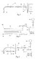
- FIG. 1is a plane view of an implant system for treating urinary incontinence in humans.
- FIG. 2is a plane view of a system of surgical tools that can be use to implant the system shown in FIG. 1 .
- FIG. 3is a plane view of test screening system that can used when the system shown in FIG. 1 is implanted in a two stage surgical procedure.
- FIG. 4is a plane view of a clinical programmer that can be used in conjunction with the system shown in FIG. 1 .
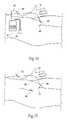
- FIGS. 5A and 5Bare anterior anatomic views of the system shown in FIG. 1 after implantation in an adipose tissue region at or near the pubic symphysis.
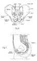
- FIG. 6is an anterior anatomic view of the pelvic girdle in a human.
- FIG. 7is a lateral section view of the pelvic girdle region shown in FIG. 6 .
- FIG. 8is an inferior view of the pelvic girdle region shown in FIG. 6 .
- FIGS. 9 to 20illustrate steps of implanting the system shown in FIG. 1 in a single surgical procedure.
- FIGS. 21 to 30illustrate steps of implanting the system shown in FIG. 1 in a two stage surgical procedure.
- FIG. 31is an anterior anatomic view of the system shown in FIG. 1 after implantation, showing the use of the clinical programmer shown in FIG. 4 to program the system.
- FIG. 32is an anterior anatomic view of the system shown in FIG. 1 after implantation, showing the use of a controller to operate the system.
- FIG. 33is an anatomic section view of a region of adipose tissue.
- FIGS. 34 and 35are anatomic section views of the adipose tissue region shown in FIG. 33 with a single lead and electrode associated with the system shown in FIG. 1 , after having been implanted.
- FIG. 36is a side interior view of a representative embodiment of a lead of the type shown in FIGS. 34 and 35 .
- FIG. 37is an end section view of the lead taken generally along line 37 - 37 in FIG. 36 .
- FIG. 38Ais an elevation view, in section, of a lead and electrode of the type shown in FIGS. 34 and 35 residing within an introducer sheath for implantation in a targeted tissue region, the anchoring members being shown retracted within the sheath.
- FIG. 38Bis an elevation view, in section, of a lead and electrode of the type shown in FIG. 39 after withdrawal of the introducer sheath 32 , the anchoring members being shown extended for use.
- FIG. 39is an elevation view of an alternative representative embodiment of lead having anchoring members.
- FIG. 40is a plane view of a kit packaging the implant system shown in FIG. 1 for use.
- FIG. 41is a plane view of two kits that facilitate the implantation of an implant system shown in FIG. 1 in a two stage surgical procedure.
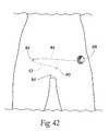
- FIG. 42is an anterior anatomic view of an embodiment of an external pulse generator coupled to a lead and electrode during the test stage of a two step surgical procedure for implanting the system shown in FIG. 1 .
- FIG. 1shows an implant system 10 for treating urinary incontinence in humans.
- the implant system 10includes an implantable lead 12 having a proximal and a distal end.
- the proximal endcarries a plug 22 , which is desirably of an industry-standard size, for coupling to an industry-sized connector 14 on a implantable pulse generator 18 .
- the distal endincludes at least one electrically conductive surface, which will also in shorthand be called an electrode 16 .
- the leadelectrically connects the electrode 16 to the connector 14 , and this to the implantable pulse generator 18 itself, while electrically insulating the wire from the body tissue except at the electrode 16 .
- the lead 12 and electrode 16are sized and configured to be implanted percutaneously in tissue, and to be tolerated by an individual during extended use without pain or discomfort.
- the comfortis both in terms of the individual's sensory perception of the electrical waveforms that the electrode applies, as well as the individual's sensory perception of the physical presence of the electrode and lead.
- the lead 12 and electrode 16are desirably “imperceptible.”
- the lead 12 and electrode 16are sized and configured to reside with stability in soft or adipose tissue 54 in the lower anterior pelvic region of the body (see FIG. 5 ). It has been discovered that, when properly placed in this region, a single lead/electrode 16 is uniquely able to deliver electrical stimulation current simultaneously to both left and right branches of the dorsal genital nerves, present near the clitoris in a female and near the base of the penis of a male (see FIGS. 5A and 5B ). Specific features of the lead 12 and electrode 16 that make them well suited for this purpose, as well as other purposes, will be described in greater detail later.
- the implant system 10also includes an implantable pulse generator 18 .
- the implantable pulse generator 18includes a circuit that generates electrical stimulation waveforms.
- An on-board batteryprovides the power.
- the implantable pulse generator 18also includes an on-board, programmable microprocessor, which carries embedded code. The code expresses pre-programmed rules or algorithms under which the desired electrical stimulation waveforms are generated by the circuit.
- the metal case of the implantable pulse generatoralso serves as the return electrode for the stimulus current introduced by the lead/electrode when operated in a monopolar configuration.
- the implantable pulse generator 18is sized and configured to be implanted subcutaneously in tissue, desirably in a subcutaneous pocket remote from the electrode 16 and using a minimally invasive surgical procedure.
- the implantation sitecan comprise a tissue region on the posterior hip.
- the implantation sitecan comprise a more medial tissue region in the lower abdomen.
- the implantable pulse generator 18can reside for extended use without causing pain and/or discomfort and/or without effecting body image.
- the implant system 10includes an external patient controller 26 (see FIG. 5A also).
- the controller 26is sized and configured to be held by the individual to transcutaneously activate and deactivate or modify the output of the implantable pulse generator.
- the controller 26may, e.g., be a simple magnet that, when placed near the site where the implantable pulse generator 18 is implanted (see FIG. 32 ), toggles a magnetic switch within the implantable pulse generator 18 between an on condition and an off condition, or advances through a sequence of alternative stimulus modes pre-programmed by the clinician into implantable pulse generator 18 .
- the controller 26may comprise more sophisticated circuitry that would allow the individual to make these selections through an RF field (magnetic and/or electric) that passes through the skin and tissue within an arm's length distance from the implantable pulse generator.
- the implantable pulse generator 18when switched on, the implantable pulse generator 18 generates prescribed stimulation waveforms through the lead 12 and to the electrode 16 . These waveforms bilaterally stimulate the left and right branches of the dorsal genital nerves in a manner that achieves the desired physiologic response.
- the implant system 10 shown in FIG. 1makes desirable a system of physician surgical tools (shown in FIG. 2 ) to facilitate implantation of the implant system 10 in the intended way, desirably on an outpatient basis.
- the surgical tool system 28 shown in FIG. 2includes a needle 30 (or trocar) and a companion introducer sleeve 32 .
- the sleeve 32is electrically insulated or insulated except at its tip.
- the needle 30is also electrically insulated, except at its tip.
- the tool system 28also includes an external pulse generator 34 , which operates to generate stimulation wave pulses of the same type as the implantable pulse generator 18 .
- the external pulse generator 34includes a connector cable 36 to couple the external pulse generator 34 to the needle 30 .
- a patch electrode 38is also included, which is to be placed on the skin of the individual and coupled to the external pulse generator 34 , to serve as a return path for the stimulation waveforms.
- the needle 30is placed tip-first into the sleeve 32 , and the sleeve 32 and needle 30 are advanced percutaneously into the targeted tissue region in the lower abdomen.
- the needle 30 and return electrode 38are coupled to the external pulse generator 34 , to apply stimulation waveforms through the tip of the needle concurrent with positioning of the needle 30 .
- the physiciancan probe the tissue region, penetrating and withdrawing the needle 30 as necessary in a minimally invasive way, until a subcutaneous location where optimal intended stimulation results are realized.
- the needle 30can be withdrawn from the sleeve 32 , followed by insertion of the lead 12 , electrode-first, through the sleeve 32 into the location. Then the sleeve 32 is withdrawn which fixes the location of the electrode 16 , as will be described in greater detail later.
- the external pulse generator 34is coupled to the lead 12 through the cable 36 to confirm that the electrode 16 resides in the desired location before tunneling the lead.
- the tool system 28also includes a tunneling tool 40 .
- the tunneling tool 40is manipulated by the physician to route the lead 12 subcutaneously to the pocket site where the implantable pulse generator 18 is to be implanted.
- the lead 12is coupled to the implantable pulse generator 18 .
- the lead 12 and implantable pulse generator 18are placed into the subcutaneous pocket, which is sutured closed.
- the implant system 10can be implanted in the manner shown in FIGS. 5A and 5B .
- the surgical tool system 28is used to implant the implant system 10 in a single surgical procedure.
- a two-stage surgical procedurecan be used.
- the first stagecomprises a screening phase that performs test stimulation using a temporary external pulse generator to evaluate if an individual is a suitable candidate for extended placement of the implantable pulse generator.
- the first stagecan be conducted, e.g., during a nominal two week period. If the patient is a suitable candidate, the second stage can be scheduled, which is the implantation of the implantable pulse generator 18 itself, as described above.
- a test screening system 42(shown in FIG. 3 ) can be provided to facilitate the two stage procedure.
- the test screening system 42includes the lead 12 and electrode 16 , which are the same as those included with the implant system 10 shown in FIG. 1 .
- the test screening system 42also includes a percutaneous extension cable 44 , which is sized and configured to be tunneled subcutaneously from the pocket site to a remote site (e.g. 5-10 cm medially) where it exits the skin.
- the percutaneous extension cablehas a proximal and distal end.
- the proximal endcarries a receptacle 46 for connection to the industry-standard size plug on the end of the lead 12 .
- the distal end of the percutaneous extension cable 44carries a plug 48 that couples to an external test cable 88 , which itself is coupled to an external pulse generator 34 , which the test screening system 42 further includes.
- the external pulse generator 34can also be of the same type previously described in connection with the surgical tool system 28 .
- the patch return electrode 38is included, or is otherwise available, to be coupled to the external pulse generator 34 .
- An alternative form of an external pulse generator 34usable with the test screening system 42 , will be described later.
- the test screening system 42also includes the external test cable 88 .
- One end of the external test cable 88carries a plug 90 to connect to the external pulse generator 34 .
- the other end of the external test cable 88includes a connector to receive the plug 48 of the percutaneous extension cable 44 .
- This end of the external test cable 88can also be sized and configured to connect directly to the surface patch electrode 38 .
- the physicianmakes use of the needle 30 and sleeve 32 of a surgical tool system 28 to implant the electrode 16 and lead 12 in the desired location, in the manner previously described.
- These components of a surgical tool system 28can be provided with the test screening system 42 .
- the percutaneous extension cable 44is coupled to the lead 12 .
- the physiciansubcutaneously tunnels the percutaneous extension cable 44 to a suitable exit site, which is desirably remote from the site where the pocket for the implanted pulse generator is to be created in the second phase. Further details of this will be described in greater detail later.
- a short length of the percutaneous extension cable 44 that carries the plug 48extends outside the exit site, for coupling the electrode 16 to the external pulse generator 34 via the test cable 88 .
- the return patch electrode 38is also coupled to the external pulse generator 34 .
- the individual patientwears the external pulse generator 34 and return patch electrode 38 for the prescribed test period.
- the external pulse generator 34supplies the prescribed stimulation regime. If an improvement in urinary continence is achieved, the second phase is warranted. In the second phase, the percutaneous extension cable 44 is removed and discarded, and the implantable pulse generator is connected to the lead 12 and installed in a pocket remote from the electrode 16 in the manner previously described.
- a clinical tool system 50is desirably provided to condition the implantable pulse generator 18 to perform in the intended manner.
- the clinical tool system 50includes a clinical programmer 52 and perhaps a separate wand connected to the programmer by a cable.
- the clinical programmer 52can be placed into transcutaneous communication with an implantable pulse generator 18 , e.g., through a radio-frequency magnetic and/or electric field (see FIG. 31 ), or using a wand.
- the clinical programmer 52may incorporate a custom program operating on a handheld computer or other personal digital appliance (PDA). Should a personal digital appliance be used with a custom program, then the circuitry necessary to generate and detect the RF fields used to communicate with the implantable pulse generator would be located in the wand.
- PDApersonal digital appliance
- the clinical programmer 52 or PDAincludes an on-board microprocessor powered by a rechargeable, on-board battery (not shown).
- the microprocessorcarries embedded code which may include pre-programmed rules or algorithms that allow a clinician to remotely download program stimulus parameters and stimulus sequences parameters into the implantable pulse generator.
- the microprocessor of the clinical programmer 52is also desirably able to interrogate the implantable pulse generator and upload operational data from the implanrable pulse generator.
- certain components of the implant system 10are sized and configured to be implanted in adipose tissue in a particular location in an individual's lower abdomen, where it has been discovered that effective bilateral stimulation of both the left and right branches of the dorsal genital nerves can be achieved with a single electrode.
- the main anatomic landmark guiding the unique placement of these componentsis the pubic symphysis.
- the hip bonesare two large, irregularly shaped bones, each of which develops from the fusion of three bones, the ilium, ischium, and pubis.
- the iliumis the superior, fan-shaped part of the hip bone.
- the ala of the iliumrepresents the spread of the fan.
- the ilium crestrepresents the rim of the fan. It has a curve that follows the contour of the ala between the anterior and posterior superior iliac spines.
- the sacrumis formed by the fusion of five originally separate sacral vertebrae.
- the hip bonesare joined at the pubic symphysis anteriorly and to the sacrum posteriorly to form the pelvic girdle (see FIG. 6 ).
- the pelvic girdleis attached to the lower limbs.
- the abdominal viscerae.g., the ileum and sigmoid colon
- the pelvic viscerae.g., the urinary bladder and female reproductive organs such as the uterus and ovaries.
- the pudendal nerveis derived at the sacral plexus from the anterior divisions of the ventral rami of S 2 through S 4 .
- the pudendal nerveextends bilaterally, in separate branches on left and right sides of the pelvic girdle. Each branch accompanies the interior pudendal artery and leaves the pelvis through the left and right greater sciatic foramens between the piriformis and coccygeus muscles.
- the brancheshook around the ischial spine and sacrospinous ligament and enter the skin and muscles of the perineum through the left and right lesser sciatic foramen.
- the bilateral left and right brachesextend anteriorly through the perineum, each ending as the dorsal genital nerve of the penis or clitoris.
- the genital nervesare the chief sensory nerve of the external genitalia.
- the FIGS.are largely based upon the anatomy of a female, but the parts of the male perineum are homologues of the female.
- adipose tissue 54overlays the pubic symphysis.
- the bilateral branches of the genital nervesinnervate this tissue region.
- this tissue regionis known as the mons pubis.
- the penis and scrotumextend from this region. Further discussion regarding the fixation of the lead 12 and electrode 16 in adipose tissue 54 will be described later.
- Betadineor Hibiclens Solutions for cases of Betadine allergy.
- implantation of the implant system 10 shown in FIG. 1can entail a single surgical procedure or a two-step surgical procedure. Each will now be described.
- FIGS. 9 to 20illustrate steps of implanting an implant system 10 in a single surgical procedure.
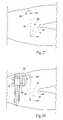
- the site for the needle puncture 60is located midline or near-midline, near the inferior border of the pubic symphysis aiming toward the clitoris (or the base of the penis in males).
- Local anesthesiae.g., 1% Lidocaine (2-5 ccs) or equivalent—is injected prior to making the anticipated needle 30 puncture site.
- the needle 30 and sleeve 32are advanced percutaneously into the anesthetized site 60 to a depth necessary to reach the target site between the pubic symphysis and the clitoris.
- the needle 30is coupled to the external pulse generator 34 (via the cable 36 ), to apply stimulation waveforms through the needle tip concurrent with positioning of the needle 30 .
- a patch electrode 38 placed on the skin of the individualis also coupled to the external pulse generator 34 to serve as a return path for the stimulation waveforms.
- the physicianmonitors anal pressure , and/or anal sphincter contractions, patient-reported sensations, and/or bladder contractions in concert with applying stimulation waveforms through the needle tip, penetrating and withdrawing the needle 30 as necessary m a nummally invasive way, until a subcutaneous location where bilateral stimulation of both left and right branches of the genital nerves results.
- the external pulse generator 34is disconnected and the needle 30 is withdrawn from the sleeve 32 .
- the lead 12electrode-first
- the lead 12is passed through the sleeve 32 into the location.
- the introducing sleeve 32is withdrawn, which fixes the location of the electrode 16 .
- the external pulse generator 34is again coupled to the lead 12 via the cable 36 (see FIG. 14 ) to apply stimulation pulses through the electrode 16 , to confirm that the electrode 16 resides in the location previously found. This aspect of the deployment of the electrode 16 will be described in greater detail later.
- the incision site for forming the subcutaneous pocket 56 for the implantable pulse generatorcomprises a lateral 2 cm incision 98 (see FIG. 15 ), which, in FIG. 15 , is located two finger-breaths medial to the anterior iliac spine and made in the direction of the dermatomal skin line.
- Local anesthesiae.g., 1% Lidocaine (2-5 ccs) or equivalent—is injected before making the incision in this site.
- the incision for the pocket 56is made using a skin knife.
- the incisionis made large enough to accept the index or dissecting finger of the implant physician.
- a subcutaneous pocket 56is made to accept the implantable pulse generator 18 using blunt dissection techniques of the subcutaneous tissues.
- the axis of the pocket 56follows the direction of the dermatomal skin line and the entrance site of the lead 12 /electrode 16 .
- a subcutaneous tunnelis formed for connecting the electrode 16 to the implantable pulse generator 18 .
- the size of the needle puncture site 60is increased using a skin knife.
- the tunneling tool 40(shown in FIG. 2 ) is passed through the pocket incision site 98 (see FIG. 16 ) toward and through the needle puncture site 60 .
- the tunneling tool 40desirably includes a removable blunt tip 62 (see FIG. 2 ) that is present during tunneling, but that is removed once passage through the distant incision site 60 occurs. With the blunt tip 62 removed, the lead 12 can be passed through the open lumen of the tunneling tool 40 to the pocket incision site 98 , as FIG. 17 shows. Withdrawal of the tunneling tool 40 delivers the plug 22 of the lead 12 through the pocket incision 98 into the procedural field.
- a tunneling tool 40comprising a stylet and sheath can be placed at the site of the needle puncture site and advanced toward the pocket incision. Removal of the stylet allows the physician to pass the lead 12 through the sheath to the pocket incision site, followed by removal of the sheath.
- the plug 22can be connected to the implantable pulse generator 18 .
- the lead 12 and implanrable pulse generator 18can be placed into the pocket 56 (as FIG. 19 shows).
- the implantable pulse generator 18is located approximately 1 cm from the surface of the skin; and the cable is oriented with an open loop of cable to allow for motion of the abdominal contents without transmitting forces along the cable and lead.
- Both wound sitesare irrigated with irrigation solutions (1 ⁇ 2 strength betadine or Hibiclens solution or equivalent).
- the skin sitesare closed using Derma-bond glue or stitches of 4-0 vicryl, as FIG. 20 shows.
- Dressingis desirably applied for about twenty-four hours.
- the incisionsare desirably kept dry for forty-eight hours.
- FIGS. 21 to 30illustrate steps of implanting an implant system 10 in a two stage surgical procedure.
- the first stageinstalls the electrode 16 and lead 12 in the manner described above, and connects the lead 12 to a temporary external pulse generator 34 . If the use of the external pulse generator 34 achieves the desired results, an implantable pulse generator is implanted in the second stage in the manner described above.
- the same preoperative antibiotics and skin prep as previously describedare performed. Under anesthesia, the electrode 16 /lead 12 are located and tunneled to the site that will later (in stage 2 ) hold the implantable pulse generator. In the first stage (see FIG. 21 ), the lead 12 is connected to the percutaneous extension cable 44 , which has been earlier described and is shown in FIG. 3 .
- a first incision 64is formed at the intended site of the pocket 56 for the implantable pulse generator 18 .
- this site 64is generally located two finger-breaths medial to the anterior iliac spine and made in the direction of the dermatomal skin line.
- the size of the needle puncture site 60is also increased using a skin knife, in preparation for tunneling.
- a tunneling tool 40(shown in FIG. 2 ) is passed through the first incision 64 toward and through the needle puncture site 60 (or vice versa), as previously described.
- the blunt tip 62 of the tunneling tool 40is removed, and the percutaneous extension cable 44 and connected lead 12 are passed through the open lumen of the tunneling tool 40 to the first incision site 64 .
- Withdrawal of the tunneling tool 40delivers the plug 48 of the percutaneous extension cable 44 through the first incision 64 into the procedural field.
- a second incision site 66is made across the pelvis away from the first incision site 64 .
- the percutaneous extension cable 44will be eventually routed to the second incision site 66 .
- the infectionoccurs away from the region where the pocket 56 for the implantable pulse generator 18 is to be formed (i.e., at the first incision site 64 ).
- the first incision site 64is thereby shielded from channel infection during the first stage, in anticipation forming a stetile pocket 56 for the implantable generator in the second stage.
- the tunneling tool 40is advanced from the second incision site 66 subcutaneously toward and through the first incision site 64 (or vice versa).
- the blunt tip 62 of the tunneling tool 40is removed, and the percutaneous extension cable 44 is passed through the open lumen of the tunneling tool 40 to the second incision site.
- Withdrawal of the tunneling tool 40delivers the plug 48 of the percutaneous extension cable 44 through the second incision 66 into the procedural field.
- a short length of the percutaneous cable 44is then secured externally to the skin with sterile tape 100 .
- the plug 48 at the end of the percutaneous extension cable 44is available for connection to the external test cable 88 (as FIG. 28 shows).
- the remainder of the percutaneous cable 44is located under the skin and is free of exposure to outside contamination.
- the sterile tape 100 covering the exit site and the re-growth of tissuemaintains this sterile barrier.
- An external pulse generator 34 of the type previously describedis coupled to the exposed plug 48 of the percutaneous extension cable through an external test cable 88 , as FIG. 28 shows.
- the patch electrode 38is placed on the skin and likewise coupled to the external pulse generator 34 .
- the individualwears the external pulse generator 34 (e.g., in a belt holster or taped to the skin) and return patch electrode 38 (on the skin) for the prescribed test period.
- the external pulse generator 34supplies the prescribed stimulation regime. If an improvement in urinary continence is achieved during the test phase, the second phase of the surgical procedure is scheduled to proceed.
- a neuromuscular stimulation device 68can be used of the type described in co-pending U.S. Pat. application Ser. No. 10/777,771, filed Feb. 12, 2004 and entided “Portable Percutaneous Assemblies, Systems, and Methods for Providing Highly Selective Functional or Therapeutic Neurostimulation,” which is incorporated herein by reference.
- the device 68comprises a skin-worn patch or carrier, which can be carried, e.g., by use of a pressure-sensitive adhesive, without discomfort and without affecting body image on the torso of an individual near the second incision.
- the carriercarries an on-board electronics pod, which generates the desired electrical current patterns.
- the podhouses microprocessor-based, programmable circuitry that generates stimulus currents, time or sequence stimulation pulses, and logs and monitors usage.
- the electronics podalso includes an electrode connection region, to physically and electrically couple the lead 12 to the circuitry of the electronics pod.
- the carrieralso includes a power input bay, to receive a small, lightweight, primary cell battery, which can be released and replaced as prescribed.
- the batteryprovides power to the electronics pod. It is contemplated that, in a typical regime during stage one, the individual will be instructed to regularly remove and discard the battery (e.g., about once a day or once a week), replacing it with a fresh battery. This arrangement simplifies meeting the power demands of the electronics pod.
- the use of the neuromuscular stimulation deviceparallels a normal, accustomed medication regime, with the battery being replaced at a prescribed frequency similar to an individual administering a medication regime in pill form.
- the same preoperative antibiotics and skin prep as previously describedare performed.
- the external pulse generator 34 , return electrode 38 , and external test cable 88are disconnected from the percutaneous extension cable 44 .
- the first and second incisions 64 and 66are reopened.
- the connection between the percutaneous extension cable 44 and lead 12is disconnected.
- the percutaneous extension cable 44is removed through the second incision 66 and discarded, as FIG. 29 shows.
- the first incision 64is enlarged to form a subcutaneous pocket 56 to accept the implantable pulse generator 18 using blunt dissection techniques of the subcutaneous tissues, as previously described (see FIG. 30 ).
- the connector 14 of the lead 12is extracted through the pocket 56 into the procedural field.
- the leadWith the pocket 56 formed (see FIG. 18 ), and the lead 12 delivered into the procedural field, the lead can now be connected to the implantable pulse generator 18 .
- the lead 12 and implantable pulse generator 18can be placed into the pocket 56 (as FIG. 19 shows).
- the implantable pulse generatoris located approximately 1 cm from the surface of the skin; and the cable is oriented with an open loop of cable to allow for motion of the abdominal contents without transmitting forces along the cable and lead.
- the wound sitesare irrigated with irrigation solutions (1/2 strength betadine or Hibiclens solution).
- irrigation solutions1/2 strength betadine or Hibiclens solution.
- the skin sitesare closed using Derma-bond glue or stitches of 4-0 vicryl, as FIG. 20 shows.
- Dressingis desirably applied for about twenty-four hours.
- the incisionsare desirably kept dry for forty-eight hours.
- Neurostimulation leads and electrodes that may be well suited for implantation in muscle tissueare not well not suited for implantation in soft adipose tissue 54 in the targeted location at or near the pubic symphysis.
- adipose tissue 54is unlike muscle tissue, and also because the vascularization and innervation of tissue at or near the pubic symphysis is unlike tissue in a muscle mass.
- Muscular tissueis formed by tough bundles of fibers with intermediate areolar tissue. The fibers consist of a contractile substance enclosed in a tubular sheath. The fibers lend bulk, density, and strength to muscle tissue that are not found in soft adipose tissue 54 . Muscles are also not innervated with sensory nerves or highly vascularized with blood vessels to the extent found in the pubic region of the body.
- Adipose tissue 54(see FIG. 33 ) consists of small vesicles, called fat-cells, lodged in the meshes of highly vascularized areolar tissue containing minute veins, minute arteries, and capillary blood vessels.
- the fat-cellsvary in size, but are about the average diameter of 1/500 of an inch. They are formed of an exceedingly delicate protoplasmic membrane, filled with fatty matter, which is liquid during life and turns solid after death. They are round or spherical where they have not been subject to pressure; otherwise they assume a more or less angular outline.
- the fat-cellsare contained in clusters in the areolae of fine connective tissue, and are held together mainly by a network of capillary blood vessels, which are distributed to them.
- the lead 12 and electrode 16are sized and configured to be inserted into and to rest in soft adipose tissue 54 (see FIG. 34 ) in the lower abdomen without causing pain or discomfort or impact body image. Desirably, the lead 12 and electrode 16 can be inserted using a small (e.g., smaller than 16 gauge) introducer with minimal tissue trauma.
- the lead 12 and electrode 16are formed from a biocompatible and electrochemically suitable material and possess no sharp features that can irritate tissue during extended use.
- the lead 12 and electrode 16possess mechanical characteristics including mechanical compliance (flexibility) along their axis (axially), as well as perpendicular to their axis (radially), and unable to transmit torque, to flexibly respond to dynamic stretching, bending, and crushing forces that can be encountered within soft, mobile adipose tissue 54 in this body region without damage or breakage, and to accommodate relative movement of the implantable pulse generator coupled to the lead 12 without imposing force or torque to the electrode 16 which tends to dislodge the electrode.
- the lead 12 and electrode 16desirably include an anchoring means 70 for providing retention strength to resist migration within or extrusion from soft, mobile adipose tissue 54 in this body region in response to force conditions normally encountered during periods of extended use.
- the anchoring means 70is desirably sized and configured to permit the electrode 16 position to be adjusted easily during insertion, allowing placement at the optimal location where bilateral stimulation of the left and right branches of the genital nerves occurs.
- the anchoring means 70functions to hold the electrode at the implanted location despite the motion of the tissue and small forces transmitted by the lead due to relative motion of the connected implantable pulse generator due to changes in body posture or external forces applied to the abdomen.
- the anchoring means 70should allow reliable release of the electrode 16 at higher force levels, to permit withdrawal of the implanted electrode 16 by purposeful pulling on the lead 12 at such higher force levels, without breaking or leaving fragments, should removal of the implanted electrode 16 be desired.
- FIGS. 36 and 37show a representative embodiment of a lead 12 and electrode 16 that provide the foregoing features.
- the lead 12comprises a molded or extruded component 72 , which encapsulates a coiled stranded wire element 74 .
- the wire elementmay be bifilar, as shown in FIG. 36 .
- the molded or extruded lead 12can have an outside diameter as small as about 1 mm.
- the lead 12may be approximately 10 cm to 30 cm in length.
- the coil's pitchcan be constant or, as FIG. 36 shows, the coil's pitch can alternate from high to low spacing to allow for flexibility in both compression and tension.
- the tight pitchwill allow for movement in tension, while the open pitch will allow for movement in compression.
- the electrode 16 or electrically conductive surfacecan be formed from Pair (or, alternatively, 316L stainless steel) and possess a conductive surface of approximately 10 mm 2 -20 mm 2 . This surface area provides current densities up to 2mA/mm2 with per pulse charge densities less than 0.5 ⁇ C/mm2.
- FIG. 35shows a monopolar electrode configuration.
- the casing of the implantable pulse generator 18serves as a return electrode.
- the single electrode 16is provided at the distal-most end.
- one or more additional conductive surfacescan be provided, spaced proximally from the tip electrode 16 , to provide a bipolar electrode configuration.
- the anchoring means 70takes the form of an array of flexible tines 76 or filaments proximal to the distal-most electrode 16 .
- the tines 76are desirably present relatively large, planar surfaces, and are placed in multiple rows axially along the lead 12 .
- the tines 76are normally biased toward a radially outward condition into tissue. In this condition, the large surface area and orientation of the tines 76 allow the lead 12 to resist dislodgement or migration of the electrode 16 out of the correct location in the surrounding tissue.
- the tines 76are biased toward a proximal-pointing orientation, to better resist proximal migration of the electrode 16 with lead tension.
- the tines 76are desirably made from a polymer material, e.g., high durometer silicone, polyurethane, or polypropylene, bonded to or molded with the lead 12 .
- the tines 76can be deflected toward a distal direction in response to exerting a pulling force on the lead 12 at a threshold axial force level, which is greater than expected day-to-day axial forces.
- the tines 76are sized and configured to yield during proximal passage through tissue in result to such forces, causing minimal tissue trauma, and without breaking or leaving fragments, despite the possible presence of some degree of tissue in-growth. This feature permits the withdrawal of the implanted electrode 16 , if desired, by purposeful pulling on the lead 12 at the higher axial force level.
- the anchoring means 70is prevented from fully engaging body tissue until after the electrode 16 has been deployed.
- the electrode 16is not deployed until after it has been correctly located during the implantation (installation) process.
- the lead 12 and electrode 16are intended to be percutaneously introduced through a sleeve 32 shown in FIG. 2 (this is also shown in FIG. 12 ).
- the tines 76assume a collapsed condition against the lead 12 body when within the sleeve 32 . In this condition, the tines 76 are shielded from contact with tissue.
- the sleeve 32can be withdrawn, holding the lead 12 and electrode 16 stationary (see FIG. 38B . Free of the sleeve 32 , the tines 76 spring open to assume their radially deployed condition in tissue, fixing the electrode 16 in the desired location.
- the position of the electrode 16 relative to the anchoring means 70allows for both advancement and retraction of the electrode delivery sleeve during implantation while simultaneously delivering test stimulation.
- the sleeve 32can be drawn back relative to the lead 12 to deploy the electrode 16 anchoring means 70 , but only when the physician determines that the desired electrode location has been reached.
- the withdrawal of the sleeve 32 from the lead 12causes the anchoring means 70 to deploy without changing the position of electrode 16 in the desired location (or allowing only a small and predictable, set motion of the electrode).
- the flexible, silicone-coated or polyurethane-coat lead 12 and electrode 16are left implanted in the tissue.
- the anchoring means 70can include an open-form conical structure 100 proximal to the distal-most electrode 16 , alone or in combination with one or more arrays of flexible tines 76 spaced more proximally away from the electrode.
- the structure 100comprises an array of circumferentially spaced-apart tines 102 joined by cross members 104 , thereby forming a conically shaped basket structure that increases in diameter (i.e., by tapering radially outward) with distance from the electrode 12 .
- the tines 102 and cross members 104are desirably made from flexible or resilient wire or polymer material, so that the structure 100 can be collapsed back against the lead 12 into a low profile for introduction through the sleeve 32 . Withdrawal of the sleeve 32 frees the structure 100 to resiliendy spring into the open-form conical shape shown in FIG. 39 .
- the structure 100provides localized stabilization for the more distal regions of the lead 12 , including the electrode 16 , which is additive to the stabilization provided to the more proximal regions of the lead 12 by the more proximally spaced tines 76 .
- the structure 100 and the tines 76provide complementary (“belt-and-suspenders”) resistance against migration of the lead 12 and electrode 16 within mobile adipose tissue 54 in response to forces that tend to flex or twist the more distal regions of the lead 12 relative to more proximal regions of the lead 12 .
- kits 78 , 80 , and 82can take various forms.
- each kit 78 , 80 , and 82comprises a sterile, wrapped assembly.
- Each kit 78 , 80 , and 82includes an interior tray 84 made, e.g., from die cut cardboard, plastic sheet, or thermo-formed plastic material, which hold the contents.
- Each kit 78 , 80 , and 82also preferably includes directions 86 for using the contents of the kit to carry out a desired procedure.
- the directions 86can, of course vary.
- the directions 86shall be physically present in the kits, but can also be supplied separately.
- the directions 86can be embodied in separate instruction manuals, or in video or audio tapes, CD's, and DVD's.
- the instructions 86 for usecan also be available through an internet web page.
- kits 78 , 80 , and 82can vary.
- a representative kit 78is shown for carrying out a single stage implant procedure as previously described.
- the kit 78includes the implant system 10 comprising the implantable lead 12 and electrode 16 , an implantable pulse generator 18 , and an external controller 26 .
- the kit 78also includes the surgical tool system 28 comprising the needle 30 , sleeve 32 , and tunneling tool 40 .
- An external pulse generator 34can also be provided, but this device will typically be available in the surgical suite.
- the instructions 86 for use in the kit 78direct use of these instruments to implant the lead 12 and electrode 16 , form the subcutaneous pocket, tunnel the lead 12 , and implant the implantable pulse generator 18 in the subcutaneous pocket in the manner previously described and as shown in FIGS. 9 to 20 .
- the instructions 86 for usecan also direct use of the external controller 26 to operate the implantable pulse generator 18 , as well as use of a clinician programmer 52 to program the implantable pulse generator 18 .
- kits 80 and 82are shown that, together, allow the physician to carry out a two stage surgical procedure.
- the first kit 80includes the test screening system 42 comprising the implantable lead 12 and electrode 16 , the percutaneous extension cable 44 , and an external pulse generator 34 and patch electrode 38 for use on a temporary basis during the screening phase.
- the kit 80also includes the surgical tools system comprising the needle 30 , sleeve 32 , and tunneling tool 40 .
- the instructions 86 for usedirect use of these instruments to install the lead 12 and electrode 16 , tunnel the lead 12 and percutaneous cable 44 , and connect the temporary external pulse generator 34 during a first surgical stage for patient screening purposes, in the manner previously described and as shown in FIGS. 21 to 27 .
- the instructions 86 for usecan also direct use of the external pulse generator 34 .
- the second kit 82contains the instruments to carry out the second stage of the procedure.
- the second kit 82includes an implantable pulse generator 18 , an external controller 26 , and a tunneling tool 40 .
- the instructions 86 for usedirect use of these components to remove the percutaneous cable 44 and couple the lead 12 to the implantable pulse generator 18 , and implant the implantable pulse generator 18 in a subcutaneous pocket in the manner previously described and as shown in FIGS. 28 to 30 and 18 to 20 .
- the instructions 86 for usecan also direct use of the external controller 26 to operate the implantable pulse generator, as well as use of a clinician programmer to program the implantable pulse generator.
Landscapes
- Health & Medical Sciences (AREA)
- General Health & Medical Sciences (AREA)
- Veterinary Medicine (AREA)
- Biomedical Technology (AREA)
- Nuclear Medicine, Radiotherapy & Molecular Imaging (AREA)
- Radiology & Medical Imaging (AREA)
- Life Sciences & Earth Sciences (AREA)
- Engineering & Computer Science (AREA)
- Animal Behavior & Ethology (AREA)
- Public Health (AREA)
- Cardiology (AREA)
- Heart & Thoracic Surgery (AREA)
- Gastroenterology & Hepatology (AREA)
- Neurology (AREA)
- Neurosurgery (AREA)
- Orthopedic Medicine & Surgery (AREA)
- Electrotherapy Devices (AREA)
Abstract
Description
Claims (20)
Priority Applications (4)
| Application Number | Priority Date | Filing Date | Title |
|---|---|---|---|
| US11/150,419US7343202B2 (en) | 2004-02-12 | 2005-06-10 | Method for affecting urinary function with electrode implantation in adipose tissue |
| US11/290,736US7865250B2 (en) | 2004-06-10 | 2005-11-30 | Methods for electrical stimulation of nerves in adipose tissue regions |
| US11/290,268US20060149345A1 (en) | 2003-09-12 | 2005-11-30 | Neuromodulation stimulation for the restoration of sexual function |
| US11/980,989US8649870B2 (en) | 2004-02-12 | 2007-10-31 | Systems and methods including lead and electrode structures sized and configured for implantation in adipose tissue |
Applications Claiming Priority (3)
| Application Number | Priority Date | Filing Date | Title |
|---|---|---|---|
| US10/777,771US7120499B2 (en) | 2004-02-12 | 2004-02-12 | Portable percutaneous assemblies, systems and methods for providing highly selective functional or therapeutic neuromuscular stimulation |
| US57874204P | 2004-06-10 | 2004-06-10 | |
| US11/150,419US7343202B2 (en) | 2004-02-12 | 2005-06-10 | Method for affecting urinary function with electrode implantation in adipose tissue |
Related Parent Applications (2)
| Application Number | Title | Priority Date | Filing Date |
|---|---|---|---|
| US10/777,771Continuation-In-PartUS7120499B2 (en) | 2004-02-12 | 2004-02-12 | Portable percutaneous assemblies, systems and methods for providing highly selective functional or therapeutic neuromuscular stimulation |
| US11/545,339Continuation-In-PartUS7571002B2 (en) | 2004-02-12 | 2006-10-10 | Portable percutaneous assemblies, systems and methods for providing highly selective functional or therapeutic neuromuscular stimulation |
Related Child Applications (3)
| Application Number | Title | Priority Date | Filing Date |
|---|---|---|---|
| US11/290,268Continuation-In-PartUS20060149345A1 (en) | 2003-09-12 | 2005-11-30 | Neuromodulation stimulation for the restoration of sexual function |
| US11/290,736Continuation-In-PartUS7865250B2 (en) | 2004-06-10 | 2005-11-30 | Methods for electrical stimulation of nerves in adipose tissue regions |
| US11/980,989ContinuationUS8649870B2 (en) | 2004-02-12 | 2007-10-31 | Systems and methods including lead and electrode structures sized and configured for implantation in adipose tissue |
Publications (2)
| Publication Number | Publication Date |
|---|---|
| US20060004429A1 US20060004429A1 (en) | 2006-01-05 |
| US7343202B2true US7343202B2 (en) | 2008-03-11 |
Family
ID=39185297
Family Applications (2)
| Application Number | Title | Priority Date | Filing Date |
|---|---|---|---|
| US11/150,419Expired - LifetimeUS7343202B2 (en) | 2003-09-12 | 2005-06-10 | Method for affecting urinary function with electrode implantation in adipose tissue |
| US11/980,989Expired - Fee RelatedUS8649870B2 (en) | 2004-02-12 | 2007-10-31 | Systems and methods including lead and electrode structures sized and configured for implantation in adipose tissue |
Family Applications After (1)
| Application Number | Title | Priority Date | Filing Date |
|---|---|---|---|
| US11/980,989Expired - Fee RelatedUS8649870B2 (en) | 2004-02-12 | 2007-10-31 | Systems and methods including lead and electrode structures sized and configured for implantation in adipose tissue |
Country Status (1)
| Country | Link |
|---|---|
| US (2) | US7343202B2 (en) |
Cited By (62)
| Publication number | Priority date | Publication date | Assignee | Title |
|---|---|---|---|---|
| US20050278000A1 (en)* | 2004-06-10 | 2005-12-15 | Strother Robert B | Implantable pulse generator for providing functional and/or therapeutic stimulation of muscles and/or nerves and/or central nervous system tissue |
| US20060173507A1 (en)* | 2004-06-10 | 2006-08-03 | Ndi Medical, Llc | Systems for electrical stimulation of nerves in adipose tissue regions |
| US20070060980A1 (en)* | 2004-06-10 | 2007-03-15 | Ndi Medical, Llc | Implantable pulse generator systems and methods for providing functional and/or therapeutic stimulation of muscles and/or nerves and/or central nervous system tissue |
| US20070060968A1 (en)* | 2004-06-10 | 2007-03-15 | Ndi Medical, Llc | Implantable pulse generator systems and methods for providing functional and/or therapeutic stimulation of muscles and/or nerves and/or central nervous system tissue |
| US20070265675A1 (en)* | 2006-05-09 | 2007-11-15 | Ams Research Corporation | Testing Efficacy of Therapeutic Mechanical or Electrical Nerve or Muscle Stimulation |
| US20070293910A1 (en)* | 2004-06-10 | 2007-12-20 | Ndi Medical, Inc. | Implantable pulse generator for providing functional and/or therapeutic stimulation of muscles and/or nerves and/or central nervous system tissue |
| US20080071322A1 (en)* | 2004-02-12 | 2008-03-20 | Ndi Medical, Llc | Systems and methods including lead and electrode structures sized and configured for implantation in adipose tissue |
| US20080161874A1 (en)* | 2004-02-12 | 2008-07-03 | Ndi Medical, Inc. | Systems and methods for a trial stage and/or long-term treatment of disorders of the body using neurostimulation |
| US20080161876A1 (en)* | 2006-12-21 | 2008-07-03 | Ams Research Corporation | Electrode implantation in male external urinary sphincter |
| US20090012592A1 (en)* | 2006-07-10 | 2009-01-08 | Ams Research Corporation | Tissue anchor |
| US20090036946A1 (en)* | 2001-11-29 | 2009-02-05 | American Medical Systems, Inc. | Pelvic disorder treatments |
| US20090043356A1 (en)* | 2006-03-03 | 2009-02-12 | Ams Research Corporation | Electrode Sling for Treating Stress and Urge Incontinence |
| US20090248095A1 (en)* | 2008-04-01 | 2009-10-01 | Boston Scientific Neuromodulation Corporation | Anchoring units for leads of implantable electric stimulation systems and methods of making and using |
| US20090254151A1 (en)* | 2008-04-02 | 2009-10-08 | Boston Scientific Neuromodulation Corporation | Lead anchor for implantable devices and methods of manufacture and use |
| US7761167B2 (en) | 2004-06-10 | 2010-07-20 | Medtronic Urinary Solutions, Inc. | Systems and methods for clinician control of stimulation systems |
| US20100217340A1 (en)* | 2009-02-23 | 2010-08-26 | Ams Research Corporation | Implantable Medical Device Connector System |
| US20100256696A1 (en)* | 2009-04-07 | 2010-10-07 | Boston Scientific Neuromodulation Corporation | Anchoring Units For Implantable Electrical Stimulation Systems And Methods Of Making And Using |
| US20100274336A1 (en)* | 2009-04-27 | 2010-10-28 | Boston Scientific Neuromodulation Corporation | Torque lock anchor and methods and devices using the anchor |
| US20110178573A1 (en)* | 2009-04-27 | 2011-07-21 | Boston Scientific Neuromodulation Corporation | Torque lock anchor and methods and devices using the anchor |
| US20120016377A1 (en)* | 2010-07-15 | 2012-01-19 | Greatbatch Ltd. | Tunneling tool for implantable leads |
| US8160710B2 (en) | 2006-07-10 | 2012-04-17 | Ams Research Corporation | Systems and methods for implanting tissue stimulation electrodes in the pelvic region |
| US8195304B2 (en) | 2004-06-10 | 2012-06-05 | Medtronic Urinary Solutions, Inc. | Implantable systems and methods for acquisition and processing of electrical signals |
| US8380312B2 (en) | 2009-12-31 | 2013-02-19 | Ams Research Corporation | Multi-zone stimulation implant system and method |
| US8467875B2 (en) | 2004-02-12 | 2013-06-18 | Medtronic, Inc. | Stimulation of dorsal genital nerves to treat urologic dysfunctions |
| US8641210B2 (en) | 2011-11-30 | 2014-02-04 | Izi Medical Products | Retro-reflective marker including colored mounting portion |
| US8661573B2 (en) | 2012-02-29 | 2014-03-04 | Izi Medical Products | Protective cover for medical device having adhesive mechanism |
| US8774942B2 (en) | 2007-07-10 | 2014-07-08 | Ams Research Corporation | Tissue anchor |
| US9216563B2 (en) | 2013-08-19 | 2015-12-22 | Boston Scientific Neuromodulation Corporation | Lead anchor with adhesive and systems and methods using the lead anchor |
| US9220887B2 (en) | 2011-06-09 | 2015-12-29 | Astora Women's Health LLC | Electrode lead including a deployable tissue anchor |
| US9364658B2 (en) | 2014-03-03 | 2016-06-14 | Boston Scientific Neuromodulation Corporation | Electrical stimulation leads with multiple anchoring units and methods of making and using |
| US20160199096A1 (en)* | 2015-01-13 | 2016-07-14 | Boston Scientific Neuromodulation Corporation | Insertion tool for implanting a paddle lead and methods and systems utilizing the tool |
| US9415212B2 (en) | 2014-02-28 | 2016-08-16 | Boston Scientific Neuromodulation Corporation | Side loading lead anchor and methods of making and using thereof |
| US9427573B2 (en) | 2007-07-10 | 2016-08-30 | Astora Women's Health, Llc | Deployable electrode lead anchor |
| US9480846B2 (en) | 2006-05-17 | 2016-11-01 | Medtronic Urinary Solutions, Inc. | Systems and methods for patient control of stimulation systems |
| US9517334B2 (en) | 2013-08-19 | 2016-12-13 | Boston Scientific Neuromodulation Corporation | Lead anchors and systems and methods employing the lead anchors |
| US9533141B2 (en) | 2014-07-07 | 2017-01-03 | Boston Scientific Neuromodulation Corporation | Electrical stimulation leads and systems with elongate anchoring elements |
| US9539433B1 (en) | 2009-03-18 | 2017-01-10 | Astora Women's Health, Llc | Electrode implantation in a pelvic floor muscular structure |
| US9636498B2 (en) | 2015-08-03 | 2017-05-02 | Boston Scientific Neuromodulation Corporation | Lead anchor with a wedge and systems using the lead anchor |
| US9649489B2 (en) | 2014-06-02 | 2017-05-16 | Boston Scientific Neuromodulation Corporation | Electrical stimulation leads and systems with anchoring units having struts and methods of making and using |
| US9669210B2 (en) | 2014-04-22 | 2017-06-06 | Boston Scientific Neuromodulation Corporation | Electrical stimulation leads and systems with folding anchoring units and methods of making and using |
| US9731112B2 (en) | 2011-09-08 | 2017-08-15 | Paul J. Gindele | Implantable electrode assembly |
| US9744354B2 (en) | 2008-12-31 | 2017-08-29 | Cyberonics, Inc. | Obstructive sleep apnea treatment devices, systems and methods |
| US9987482B2 (en) | 2014-05-27 | 2018-06-05 | Boston Scientific Neuromodulation Corporation | Systems and methods for making and using reversible mechanical lead anchors for electrical stimulation systems |
| US10052484B2 (en) | 2011-10-03 | 2018-08-21 | Cyberonics, Inc. | Devices and methods for sleep apnea treatment |
| US10071242B2 (en) | 2016-02-29 | 2018-09-11 | Boston Scientific Neuromodulation Corporation | Lead anchor for an electrical stimulation system |
| US10231645B2 (en) | 2011-01-28 | 2019-03-19 | Livanova Usa, Inc. | Screening devices and methods for obstructive sleep apnea therapy |
| US10369354B2 (en) | 2016-05-17 | 2019-08-06 | Boston Scientific Neuromodulation Corporation | Systems and method for anchoring a lead for neurostimulation of a target anatomy |
| US10384055B2 (en) | 2013-12-04 | 2019-08-20 | Boston Scientific Neuromodulation Corporation | Insertion tool for implanting a paddle lead and methods and systems utilizing the tool |
| US10406353B2 (en) | 2013-05-14 | 2019-09-10 | Boston Scientific Neuromodulation Corporation | Electrical stimulation leads with anchoring unit and electrode arrangement and methods of making and using |
| US10589089B2 (en) | 2017-10-25 | 2020-03-17 | Epineuron Technologies Inc. | Systems and methods for delivering neuroregenerative therapy |
| US10632308B2 (en) | 2006-10-13 | 2020-04-28 | Livanova Usa, Inc. | Obstructive sleep apnea treatment devices, systems and methods |
| US10709886B2 (en) | 2017-02-28 | 2020-07-14 | Boston Scientific Neuromodulation Corporation | Electrical stimulation leads and systems with elongate anchoring elements and methods of making and using |
| US10835739B2 (en) | 2017-03-24 | 2020-11-17 | Boston Scientific Neuromodulation Corporation | Electrical stimulation leads and systems with elongate anchoring elements and methods of making and using |
| US10857351B2 (en) | 2017-04-28 | 2020-12-08 | Boston Scientific Neuromodulation Corporation | Lead anchors for electrical stimulation leads and systems and methods of making and using |
| WO2021080865A1 (en) | 2019-10-22 | 2021-04-29 | Hologic, Inc. | Transvaginal treatment of stress urinary incontinence |
| US11247043B2 (en) | 2019-10-01 | 2022-02-15 | Epineuron Technologies Inc. | Electrode interface devices for delivery of neuroregenerative therapy |
| US11247045B2 (en) | 2017-10-25 | 2022-02-15 | Epineuron Technologies Inc. | Systems and methods for delivering neuroregenerative therapy |
| US11383083B2 (en) | 2014-02-11 | 2022-07-12 | Livanova Usa, Inc. | Systems and methods of detecting and treating obstructive sleep apnea |
| US11471685B2 (en) | 2006-10-13 | 2022-10-18 | Livanova Usa, Inc. | Obstructive sleep apnea treatment devices, systems and methods |
| US20220347470A1 (en)* | 2018-12-20 | 2022-11-03 | Galvani Bioelectronics Limited | Neurostimulation device for blocking blood flow between electrodes |
| US11529514B2 (en) | 2011-01-28 | 2022-12-20 | Livanova Usa, Inc. | Obstructive sleep apnea treatment devices, systems and methods |
| US12357823B2 (en) | 2019-05-24 | 2025-07-15 | Inspire Medical Systems, Inc. | Systems and methods for treating incontinence |
Families Citing this family (49)
| Publication number | Priority date | Publication date | Assignee | Title |
|---|---|---|---|---|
| US20080077192A1 (en) | 2002-05-03 | 2008-03-27 | Afferent Corporation | System and method for neuro-stimulation |
| US8086318B2 (en)* | 2004-02-12 | 2011-12-27 | Ndi Medical, Llc | Portable assemblies, systems, and methods for providing functional or therapeutic neurostimulation |
| US7644714B2 (en)* | 2005-05-27 | 2010-01-12 | Apnex Medical, Inc. | Devices and methods for treating sleep disorders |
| US7809443B2 (en)* | 2006-01-31 | 2010-10-05 | Medtronic, Inc. | Electrical stimulation to alleviate chronic pelvic pain |
| AU2007243788B2 (en)* | 2006-04-04 | 2010-10-28 | Ams Research Corporation | A tunneling instrument for and method of subcutaneously passing a medical electrical lead |
| US8219202B2 (en) | 2006-04-28 | 2012-07-10 | Medtronic, Inc. | Electrical stimulation of ilioinguinal nerve to alleviate chronic pelvic pain |
| US20070253997A1 (en)* | 2006-04-28 | 2007-11-01 | Medtronic, Inc. | Drug delivery to alleviate chronic pelvic pain |
| US7881783B2 (en)* | 2006-04-28 | 2011-02-01 | Medtronics, Inc. | Implantable medical electrical stimulation lead, such as a PNE lead, and method of use |
| US20070255333A1 (en)* | 2006-04-28 | 2007-11-01 | Medtronic, Inc. | Neuromodulation therapy for perineal or dorsal branch of pudendal nerve |
| US20070255368A1 (en)* | 2006-04-28 | 2007-11-01 | Bonde Eric H | Implantable medical electrical stimulation lead with distal fixation and method |
| US7761166B2 (en) | 2006-04-28 | 2010-07-20 | Medtronic, Inc. | Electrical stimulation of iliohypogastric nerve to alleviate chronic pelvic pain |
| US9713706B2 (en)* | 2006-10-31 | 2017-07-25 | Medtronic, Inc. | Implantable medical elongated member including intermediate fixation |
| US11679261B2 (en) | 2007-03-09 | 2023-06-20 | Mainstay Medical Limited | Systems and methods for enhancing function of spine stabilization muscles associated with a spine surgery intervention |
| WO2008112178A1 (en) | 2007-03-09 | 2008-09-18 | Dan Sachs | Muscle stimulator |
| US11331488B2 (en) | 2007-03-09 | 2022-05-17 | Mainstay Medical Limited | Systems and methods for enhancing function of spine stabilization muscles associated with a spine surgery intervention |
| US9072897B2 (en) | 2007-03-09 | 2015-07-07 | Mainstay Medical Limited | Systems and methods for restoring muscle function to the lumbar spine |
| US10925637B2 (en)* | 2010-03-11 | 2021-02-23 | Mainstay Medical Limited | Methods of implanting electrode leads for use with implantable neuromuscular electrical stimulator |
| US11679262B2 (en) | 2007-03-09 | 2023-06-20 | Mainstay Medical Limited | Systems and methods for restoring muscle function to the lumbar spine |
| US7908015B2 (en)* | 2008-07-31 | 2011-03-15 | Medtronic, Inc. | Subcutaneously implantable lead including distal fixation mechanism |
| US8700177B2 (en) | 2008-08-01 | 2014-04-15 | Ndi Medical, Llc | Systems and methods for providing percutaneous electrical stimulation |
| WO2010014259A1 (en)* | 2008-08-01 | 2010-02-04 | Ndi Medical, Llc | Portable assemblies, systems, and methods for providing functional or therapeutic neurostimulation |
| EP2331201B1 (en) | 2008-10-01 | 2020-04-29 | Inspire Medical Systems, Inc. | System for treating sleep apnea transvenously |
| US9403020B2 (en) | 2008-11-04 | 2016-08-02 | Nevro Corporation | Modeling positions of implanted devices in a patient |
| JP5575789B2 (en) | 2008-11-19 | 2014-08-20 | インスパイア・メディカル・システムズ・インコーポレイテッド | How to treat sleep-disordered breathing |
| JP2012521864A (en) | 2009-03-31 | 2012-09-20 | インスパイア・メディカル・システムズ・インコーポレイテッド | Percutaneous access method in a system for treating sleep-related abnormal breathing |
| US20110004288A1 (en)* | 2009-06-12 | 2011-01-06 | Terrance Ransbury | Intravascular implantable device having integrated anchor mechanism |
| EP2544759B1 (en) | 2010-03-11 | 2017-05-31 | Mainstay Medical Limited | Modular stimulator for treatment of back pain, implantable rf ablation system |
| US11786725B2 (en) | 2012-06-13 | 2023-10-17 | Mainstay Medical Limited | Systems and methods for restoring muscle function to the lumbar spine and kits for implanting the same |
| US11684774B2 (en) | 2010-03-11 | 2023-06-27 | Mainstay Medical Limited | Electrical stimulator for treatment of back pain and methods of use |
| US9950159B2 (en) | 2013-10-23 | 2018-04-24 | Mainstay Medical Limited | Systems and methods for restoring muscle function to the lumbar spine and kits for implanting the same |
| US12097365B2 (en) | 2010-03-11 | 2024-09-24 | Mainstay Medical Limited | Electrical stimulator for the treatment of back pain and methods of use |
| US8965482B2 (en) | 2010-09-30 | 2015-02-24 | Nevro Corporation | Systems and methods for positioning implanted devices in a patient |
| US8805519B2 (en) | 2010-09-30 | 2014-08-12 | Nevro Corporation | Systems and methods for detecting intrathecal penetration |
| AU2013211937B2 (en) | 2012-01-25 | 2016-07-28 | Nevro Corporation | Lead anchors and associated systems and methods |
| US10327810B2 (en) | 2016-07-05 | 2019-06-25 | Mainstay Medical Limited | Systems and methods for enhanced implantation of electrode leads between tissue layers |
| US9186501B2 (en)* | 2012-06-13 | 2015-11-17 | Mainstay Medical Limited | Systems and methods for implanting electrode leads for use with implantable neuromuscular electrical stimulator |
| US10195419B2 (en) | 2012-06-13 | 2019-02-05 | Mainstay Medical Limited | Electrode leads for use with implantable neuromuscular electrical stimulator |
| US9427565B2 (en)* | 2012-11-07 | 2016-08-30 | The Florida International University Board Of Trustees | Modular multi-channel inline connector system |
| US9440076B2 (en)* | 2013-03-15 | 2016-09-13 | Globus Medical, Inc. | Spinal cord stimulator system |
| US9265935B2 (en) | 2013-06-28 | 2016-02-23 | Nevro Corporation | Neurological stimulation lead anchors and associated systems and methods |
| WO2015196164A2 (en) | 2014-06-21 | 2015-12-23 | Accelemed, Llc | Method and apparatus for neuromodulation treatments of pain and other conditions |
| US10471268B2 (en) | 2014-10-16 | 2019-11-12 | Mainstay Medical Limited | Systems and methods for monitoring muscle rehabilitation |
| WO2017165410A1 (en) | 2016-03-21 | 2017-09-28 | Nalu Medical, Inc. | Devices and methods for positioning external devices in relation to implanted devices |
| EP3484577B1 (en) | 2016-07-18 | 2025-06-18 | Nalu Medical, Inc. | Systems for treating pelvic disorders and pain conditions |
| WO2018156953A1 (en) | 2017-02-24 | 2018-08-30 | Nalu Medical, Inc. | Apparatus with sequentially implanted stimulators |
| US10980999B2 (en) | 2017-03-09 | 2021-04-20 | Nevro Corp. | Paddle leads and delivery tools, and associated systems and methods |
| AU2018265016B2 (en) | 2017-05-09 | 2023-01-05 | Nalu Medical, Inc. | Stimulation apparatus |
| WO2019191423A1 (en) | 2018-03-29 | 2019-10-03 | Nevro Corp. | Leads having sidewall openings, and associated systems and methods |
| AU2021247476A1 (en)* | 2020-03-30 | 2022-12-08 | Berlin Heals Gmbh | An electric field or electric voltage delivering electrode system for the treatment of internal organ oedema |
Citations (75)
| Publication number | Priority date | Publication date | Assignee | Title |
|---|---|---|---|---|
| US3727616A (en) | 1971-06-15 | 1973-04-17 | Gen Dynamics Corp | Electronic system for the stimulation of biological systems |
| US3870051A (en) | 1972-04-27 | 1975-03-11 | Nat Res Dev | Urinary control |
| US3939843A (en) | 1974-03-04 | 1976-02-24 | Medtronic, Inc. | Transvenous electrode |
| US3941136A (en) | 1973-11-21 | 1976-03-02 | Neuronyx Corporation | Method for artificially inducing urination, defecation, or sexual excitation |
| US4232679A (en) | 1977-01-26 | 1980-11-11 | Pacesetter Systems, Inc. | Programmable human tissue stimulator |
| US4262678A (en) | 1979-06-28 | 1981-04-21 | Medtronic, Inc. | Pacing lead with tine protector |
| US4406288A (en) | 1981-04-06 | 1983-09-27 | Hugh P. Cash | Bladder control device and method |
| US4407303A (en) | 1980-04-21 | 1983-10-04 | Siemens Aktiengesellschaft | Endocardial electrode arrangement |
| US4569351A (en) | 1984-12-20 | 1986-02-11 | University Of Health Sciences/The Chicago Medical School | Apparatus and method for stimulating micturition and certain muscles in paraplegic mammals |
| US4585013A (en) | 1981-04-20 | 1986-04-29 | Cordis Corporation | Lumenless pervenous electrical lead and method of implantation |
| US4585005A (en) | 1984-04-06 | 1986-04-29 | Regents Of University Of California | Method and pacemaker for stimulating penile erection |
| US4607639A (en) | 1984-05-18 | 1986-08-26 | Regents Of The University Of California | Method and system for controlling bladder evacuation |
| US4703755A (en) | 1984-05-18 | 1987-11-03 | The Regents Of The University Of California | Control system for the stimulation of two bodily functions |
| US4716888A (en) | 1985-06-17 | 1988-01-05 | Cordis Corporation | Tined leads |
| US4739764A (en) | 1984-05-18 | 1988-04-26 | The Regents Of The University Of California | Method for stimulating pelvic floor muscles for regulating pelvic viscera |
| US4771779A (en) | 1984-05-18 | 1988-09-20 | The Regents Of The University Of California | System for controlling bladder evacuation |
| US4989617A (en) | 1989-07-14 | 1991-02-05 | Case Western Reserve University | Intramuscular electrode for neuromuscular stimulation system |
| US5113869A (en) | 1990-08-21 | 1992-05-19 | Telectronics Pacing Systems, Inc. | Implantable ambulatory electrocardiogram monitor |
| US5154172A (en) | 1989-11-13 | 1992-10-13 | Cyberonics, Inc. | Constant current sources with programmable voltage source |
| US5215086A (en) | 1991-05-03 | 1993-06-01 | Cyberonics, Inc. | Therapeutic treatment of migraine symptoms by stimulation |
| US5222494A (en) | 1991-07-31 | 1993-06-29 | Cyberonics, Inc. | Implantable tissue stimulator output stabilization system |
| US5257634A (en) | 1992-07-16 | 1993-11-02 | Angeion Corporation | Low impedence defibrillation catheter electrode |
| US5282845A (en) | 1990-10-01 | 1994-02-01 | Ventritex, Inc. | Multiple electrode deployable lead |
| US5300107A (en) | 1992-10-22 | 1994-04-05 | Medtronic, Inc. | Universal tined myocardial pacing lead |
| US5330515A (en) | 1992-06-17 | 1994-07-19 | Cyberonics, Inc. | Treatment of pain by vagal afferent stimulation |
| US5344439A (en)* | 1992-10-30 | 1994-09-06 | Medtronic, Inc. | Catheter with retractable anchor mechanism |
| US5370671A (en) | 1991-03-26 | 1994-12-06 | Empi, Inc. | Incontinence electrode apparatus |
| US5411537A (en) | 1993-10-29 | 1995-05-02 | Intermedics, Inc. | Rechargeable biomedical battery powered devices with recharging and control system therefor |
| US5454840A (en) | 1994-04-05 | 1995-10-03 | Krakovsky; Alexander A. | Potency package |
| US5476500A (en) | 1993-12-20 | 1995-12-19 | Ventritex, Inc. | Endocardial lead system with defibrillation electrode fixation |
| US5562717A (en) | 1992-05-23 | 1996-10-08 | Axelgaard Manufacturing Company, Ltd. | Electrical stimulation for treatment of incontinence and other neuromuscular disorders |
| US5588960A (en)* | 1994-12-01 | 1996-12-31 | Vidamed, Inc. | Transurethral needle delivery device with cystoscope and method for treatment of urinary incontinence |
| US5683447A (en) | 1995-12-19 | 1997-11-04 | Ventritex, Inc. | Lead with septal defibrillation and pacing electrodes |
| US5722999A (en) | 1995-08-02 | 1998-03-03 | Pacesetter, Inc. | System and method for storing and displaying historical medical data measured by an implantable medical device |
| US5733322A (en) | 1995-05-23 | 1998-03-31 | Medtronic, Inc. | Positive fixation percutaneous epidural neurostimulation lead |
| US5755767A (en) | 1996-08-02 | 1998-05-26 | Pacesetter, Inc. | Anti-dislodgment and anti-perforation distal tip design for transvenous lead |
| US5922015A (en) | 1996-03-14 | 1999-07-13 | Biotronik Mess- Und Therapiegeraete Gmbh & Co. Ingenieurbuero Berlin | Implantable device which permits removal without traumatizing the surrounding tissue |
| US5984854A (en) | 1996-02-15 | 1999-11-16 | Nihon Kohden Corporation | Method for treating urinary incontinence and an apparatus therefor |
| US6055457A (en) | 1998-03-13 | 2000-04-25 | Medtronic, Inc. | Single pass A-V lead with active fixation device |
| US6055456A (en) | 1999-04-29 | 2000-04-25 | Medtronic, Inc. | Single and multi-polar implantable lead for sacral nerve electrical stimulation |
| US6061596A (en) | 1995-11-24 | 2000-05-09 | Advanced Bionics Corporation | Method for conditioning pelvic musculature using an implanted microstimulator |
| US6091995A (en)* | 1996-11-08 | 2000-07-18 | Surx, Inc. | Devices, methods, and systems for shrinking tissues |
| US6181965B1 (en) | 1996-02-20 | 2001-01-30 | Advanced Bionics Corporation | Implantable microstimulator system for prevention of disorders |
| US6185452B1 (en) | 1997-02-26 | 2001-02-06 | Joseph H. Schulman | Battery-powered patient implantable device |
| US6208894B1 (en) | 1997-02-26 | 2001-03-27 | Alfred E. Mann Foundation For Scientific Research And Advanced Bionics | System of implantable devices for monitoring and/or affecting body parameters |
| US6240316B1 (en) | 1998-08-14 | 2001-05-29 | Advanced Bionics Corporation | Implantable microstimulation system for treatment of sleep apnea |
| US6266557B1 (en) | 1998-06-29 | 2001-07-24 | The Procter & Gamble Company | Biofeedback device for an incontinent person |
| US6308101B1 (en) | 1998-07-31 | 2001-10-23 | Advanced Bionics Corporation | Fully implantable cochlear implant system |
| US6381496B1 (en) | 1999-10-01 | 2002-04-30 | Advanced Bionics Corporation | Parameter context switching for an implanted device |
| US20020055761A1 (en) | 1998-07-06 | 2002-05-09 | Mann Carla M. | Implantable stimulator systems and methods for treatment of incontinence and pain |
| US20020055779A1 (en) | 1996-03-05 | 2002-05-09 | Brian J. Andrews | Neural prosthesis |
| US6432037B1 (en) | 2000-08-31 | 2002-08-13 | Flexiprobe Ltd. | Intravaginal device for electrically stimulating and/or for sensing electrical activity of muscles and/or nerves defining and surrounding the intravaginal cavity |
| US20030004553A1 (en) | 2001-03-30 | 2003-01-02 | Case Western Reserve University | Systems and methods for selectively stimulating components in, on, or near the pudendal nerve or its branches to achieve selective physiologic responses |
| US6505074B2 (en)* | 1998-10-26 | 2003-01-07 | Birinder R. Boveja | Method and apparatus for electrical stimulation adjunct (add-on) treatment of urinary incontinence and urological disorders using an external stimulator |
| US6510347B2 (en) | 2000-08-17 | 2003-01-21 | William N. Borkan | Spinal cord stimulation leads |
| US20030018365A1 (en) | 2001-07-20 | 2003-01-23 | Loeb Gerald E. | Method and apparatus for the treatment of urinary tract dysfunction |
| US6516227B1 (en) | 1999-07-27 | 2003-02-04 | Advanced Bionics Corporation | Rechargeable spinal cord stimulator system |
| US20030100930A1 (en) | 2001-11-29 | 2003-05-29 | Biocontrol Medical Ltd. | Pelvic disorder treatment device |
| US20030114905A1 (en) | 1999-10-01 | 2003-06-19 | Kuzma Janusz A. | Implantable microdevice with extended lead and remote electrode |
| US6650943B1 (en) | 2000-04-07 | 2003-11-18 | Advanced Bionics Corporation | Fully implantable neurostimulator for cavernous nerve stimulation as a therapy for erectile dysfunction and other sexual dysfunction |
| US6652449B1 (en) | 1998-10-06 | 2003-11-25 | Bio Control Medical, Ltd. | Control of urge incontinence |
| US6684109B1 (en) | 2000-09-13 | 2004-01-27 | Oscor Inc. | Endocardial lead |
| US20040088024A1 (en) | 2001-03-08 | 2004-05-06 | Firlik Andrew D. | Methods and apparatus for effectuating a lasting change in a neural-function of a patient |
| US6735475B1 (en) | 2001-01-30 | 2004-05-11 | Advanced Bionics Corporation | Fully implantable miniature neurostimulator for stimulation as a therapy for headache and/or facial pain |
| US6735474B1 (en) | 1998-07-06 | 2004-05-11 | Advanced Bionics Corporation | Implantable stimulator system and method for treatment of incontinence and pain |
| US20040111126A1 (en) | 2002-12-06 | 2004-06-10 | The Regents Of The University Of California | Methods and systems for selective control of bladder function |
| US20040162594A1 (en) | 2001-05-17 | 2004-08-19 | King Gary W. | Apparatus and method for blocking activation of tissue or conduction of action potentials while other tissue is being therapeutically activated |
| US6836684B1 (en) | 1998-10-30 | 2004-12-28 | Neurocon Aps | Method to control an overactive bladder |
| US20050055063A1 (en) | 2001-07-20 | 2005-03-10 | Loeb Gerald E. | Method and apparatus for the treatment of urinary tract dysfunction |
| US20050143787A1 (en) | 2002-05-09 | 2005-06-30 | Boveja Birinder R. | Method and system for providing electrical pulses for neuromodulation of vagus nerve(s), using rechargeable implanted pulse generator |
| US6920359B2 (en) | 2000-02-15 | 2005-07-19 | Advanced Bionics Corporation | Deep brain stimulation system for the treatment of Parkinson's Disease or other disorders |
| US6937894B1 (en) | 2001-11-08 | 2005-08-30 | Pacesetter, Inc. | Method of recharging battery for an implantable medical device |
| US20060025829A1 (en) | 2004-07-28 | 2006-02-02 | Armstrong Randolph K | Power supply monitoring for an implantable device |
| US6999819B2 (en)* | 2001-08-31 | 2006-02-14 | Medtronic, Inc. | Implantable medical electrical stimulation lead fixation method and apparatus |
| US7047078B2 (en) | 2001-03-30 | 2006-05-16 | Case Western Reserve University | Methods for stimulating components in, on, or near the pudendal nerve or its branches to achieve selective physiologic responses |
Family Cites Families (33)
| Publication number | Priority date | Publication date | Assignee | Title |
|---|---|---|---|---|
| US132969A (en)* | 1872-11-12 | Improvement | ||
| US123952A (en)* | 1872-02-20 | Improvement in loom picking mechanisms | ||
| US173507A (en)* | 1876-02-15 | Improvement in ferry-guards | ||
| US191874A (en)* | 1877-06-12 | Improvement in machines for uniting the soles to uppers of boots and shoes | ||
| US147886A (en)* | 1874-02-24 | Improvement in boiler-feeders | ||
| US239224A (en)* | 1881-03-22 | campbell | ||
| US4014346A (en)* | 1975-06-26 | 1977-03-29 | Research Corporation | Hermetically sealed cardiac pacer system and recharging system therefor |
| US4519404A (en)* | 1983-09-28 | 1985-05-28 | Fleischhacker John J | Endocardial electrode lead with conical fixation mechanism |
| US5350413B1 (en)* | 1990-06-21 | 1999-09-07 | Heart Inst Research Corp | Transcutaneous energy transfer device |
| US5144946A (en)* | 1991-08-05 | 1992-09-08 | Siemens Pacesetter, Inc. | Combined pacemaker substrate and electrical interconnect and method of assembly |
| US5400784A (en)* | 1993-10-15 | 1995-03-28 | Case Western Reserve University | Slowly penetrating inter-fascicular nerve cuff electrode and method of using |
| CA2121219A1 (en) | 1994-04-11 | 1995-10-12 | Robert L. Erickson | Methods using repositionable instructions and kits containing same |
| US5449512A (en)* | 1994-08-24 | 1995-09-12 | The Procter & Gamble Company | Anhydrous after shave lotions |
| US5945762A (en)* | 1998-02-10 | 1999-08-31 | Light Sciences Limited Partnership | Movable magnet transmitter for inducing electrical current in an implanted coil |
| US6006133A (en)* | 1998-04-03 | 1999-12-21 | Medtronic, Inc. | Implantable medical device having flat electrolytic capacitor with consolidated electrode assembly |
| US6836685B1 (en)* | 1998-04-07 | 2004-12-28 | William R. Fitz | Nerve stimulation method and apparatus for pain relief |
| US20060122660A1 (en)* | 1998-10-26 | 2006-06-08 | Boveja Birinder R | Method and system for modulating sacral nerves and/or its branches in a patient to provide therapy for urological disorders and/or fecal incontinence, using rectangular and/or complex electrical pulses |
| EP1790304B1 (en) | 1999-05-11 | 2016-08-31 | Atrionix, Inc. | Tissue ablation system including a balloon anchor wire |
| US6660265B1 (en)* | 1999-10-15 | 2003-12-09 | The Brigham & Women's Hospital, Inc. | Fresh, cryopreserved, or minimally cardiac valvular xenografts |
| US6666828B2 (en)* | 2001-06-29 | 2003-12-23 | Medtronic, Inc. | Catheter system having disposable balloon |
| US7328068B2 (en)* | 2003-03-31 | 2008-02-05 | Medtronic, Inc. | Method, system and device for treating disorders of the pelvic floor by means of electrical stimulation of the pudendal and associated nerves, and the optional delivery of drugs in association therewith |
| US7608067B2 (en) | 2002-11-06 | 2009-10-27 | Aram Bonni | Patient-adjustable incontinence device (AID) |
| JP3921221B2 (en) | 2002-11-14 | 2007-05-30 | 株式会社塚田メディカル・リサーチ | Interstitial cystitis diagnostic catheter |
| US7499758B2 (en)* | 2003-04-11 | 2009-03-03 | Cardiac Pacemakers, Inc. | Helical fixation elements for subcutaneous electrodes |
| US7343202B2 (en)* | 2004-02-12 | 2008-03-11 | Ndi Medical, Llc. | Method for affecting urinary function with electrode implantation in adipose tissue |
| US8165695B2 (en)* | 2004-02-11 | 2012-04-24 | Ethicon, Inc. | System and method for selectively stimulating different body parts |
| US20080161874A1 (en) | 2004-02-12 | 2008-07-03 | Ndi Medical, Inc. | Systems and methods for a trial stage and/or long-term treatment of disorders of the body using neurostimulation |
| US20080132969A1 (en)* | 2004-02-12 | 2008-06-05 | Ndi Medical, Inc. | Systems and methods for bilateral stimulation of left and right branches of the dorsal genital nerves to treat urologic dysfunctions |
| US8086318B2 (en) | 2004-02-12 | 2011-12-27 | Ndi Medical, Llc | Portable assemblies, systems, and methods for providing functional or therapeutic neurostimulation |
| US8467875B2 (en)* | 2004-02-12 | 2013-06-18 | Medtronic, Inc. | Stimulation of dorsal genital nerves to treat urologic dysfunctions |
| CA2566614A1 (en)* | 2004-06-10 | 2005-12-29 | Ndi Medical, Llc | Systems and methods for bilateral stimulation of left and right branches of the dorsal genital nerves to treat dysfunctions, such as urinary incontinence |
| US7894913B2 (en)* | 2004-06-10 | 2011-02-22 | Medtronic Urinary Solutions, Inc. | Systems and methods of neuromodulation stimulation for the restoration of sexual function |
| WO2006124068A1 (en) | 2005-05-13 | 2006-11-23 | Ndi Medical, Llc | Systems for electrical stimulation of nerves in adipose tissue regions |
- 2005
- 2005-06-10USUS11/150,419patent/US7343202B2/ennot_activeExpired - Lifetime
- 2007
- 2007-10-31USUS11/980,989patent/US8649870B2/ennot_activeExpired - Fee Related
Patent Citations (84)
| Publication number | Priority date | Publication date | Assignee | Title |
|---|---|---|---|---|
| US3727616A (en) | 1971-06-15 | 1973-04-17 | Gen Dynamics Corp | Electronic system for the stimulation of biological systems |
| US3870051A (en) | 1972-04-27 | 1975-03-11 | Nat Res Dev | Urinary control |
| US3941136A (en) | 1973-11-21 | 1976-03-02 | Neuronyx Corporation | Method for artificially inducing urination, defecation, or sexual excitation |
| US3939843A (en) | 1974-03-04 | 1976-02-24 | Medtronic, Inc. | Transvenous electrode |
| US4232679B1 (en) | 1977-01-26 | 1988-05-31 | ||
| US4232679A (en) | 1977-01-26 | 1980-11-11 | Pacesetter Systems, Inc. | Programmable human tissue stimulator |
| US4262678A (en) | 1979-06-28 | 1981-04-21 | Medtronic, Inc. | Pacing lead with tine protector |
| US4407303A (en) | 1980-04-21 | 1983-10-04 | Siemens Aktiengesellschaft | Endocardial electrode arrangement |
| US4406288A (en) | 1981-04-06 | 1983-09-27 | Hugh P. Cash | Bladder control device and method |
| US4585013A (en) | 1981-04-20 | 1986-04-29 | Cordis Corporation | Lumenless pervenous electrical lead and method of implantation |
| US4585005A (en) | 1984-04-06 | 1986-04-29 | Regents Of University Of California | Method and pacemaker for stimulating penile erection |
| US4703755A (en) | 1984-05-18 | 1987-11-03 | The Regents Of The University Of California | Control system for the stimulation of two bodily functions |
| US4739764A (en) | 1984-05-18 | 1988-04-26 | The Regents Of The University Of California | Method for stimulating pelvic floor muscles for regulating pelvic viscera |
| US4607639A (en) | 1984-05-18 | 1986-08-26 | Regents Of The University Of California | Method and system for controlling bladder evacuation |
| US4771779A (en) | 1984-05-18 | 1988-09-20 | The Regents Of The University Of California | System for controlling bladder evacuation |
| US4569351A (en) | 1984-12-20 | 1986-02-11 | University Of Health Sciences/The Chicago Medical School | Apparatus and method for stimulating micturition and certain muscles in paraplegic mammals |
| US4716888A (en) | 1985-06-17 | 1988-01-05 | Cordis Corporation | Tined leads |
| US4989617A (en) | 1989-07-14 | 1991-02-05 | Case Western Reserve University | Intramuscular electrode for neuromuscular stimulation system |
| US5154172A (en) | 1989-11-13 | 1992-10-13 | Cyberonics, Inc. | Constant current sources with programmable voltage source |
| US5113869A (en) | 1990-08-21 | 1992-05-19 | Telectronics Pacing Systems, Inc. | Implantable ambulatory electrocardiogram monitor |
| US5282845A (en) | 1990-10-01 | 1994-02-01 | Ventritex, Inc. | Multiple electrode deployable lead |
| US5370671A (en) | 1991-03-26 | 1994-12-06 | Empi, Inc. | Incontinence electrode apparatus |
| US5215086A (en) | 1991-05-03 | 1993-06-01 | Cyberonics, Inc. | Therapeutic treatment of migraine symptoms by stimulation |
| US5222494A (en) | 1991-07-31 | 1993-06-29 | Cyberonics, Inc. | Implantable tissue stimulator output stabilization system |
| US5562717A (en) | 1992-05-23 | 1996-10-08 | Axelgaard Manufacturing Company, Ltd. | Electrical stimulation for treatment of incontinence and other neuromuscular disorders |
| US5330515A (en) | 1992-06-17 | 1994-07-19 | Cyberonics, Inc. | Treatment of pain by vagal afferent stimulation |
| US5257634A (en) | 1992-07-16 | 1993-11-02 | Angeion Corporation | Low impedence defibrillation catheter electrode |
| US5300107A (en) | 1992-10-22 | 1994-04-05 | Medtronic, Inc. | Universal tined myocardial pacing lead |
| US5344439A (en)* | 1992-10-30 | 1994-09-06 | Medtronic, Inc. | Catheter with retractable anchor mechanism |
| US5411537A (en) | 1993-10-29 | 1995-05-02 | Intermedics, Inc. | Rechargeable biomedical battery powered devices with recharging and control system therefor |
| US5476500A (en) | 1993-12-20 | 1995-12-19 | Ventritex, Inc. | Endocardial lead system with defibrillation electrode fixation |
| US5454840A (en) | 1994-04-05 | 1995-10-03 | Krakovsky; Alexander A. | Potency package |
| US5588960A (en)* | 1994-12-01 | 1996-12-31 | Vidamed, Inc. | Transurethral needle delivery device with cystoscope and method for treatment of urinary incontinence |
| US5733322A (en) | 1995-05-23 | 1998-03-31 | Medtronic, Inc. | Positive fixation percutaneous epidural neurostimulation lead |
| US5722999A (en) | 1995-08-02 | 1998-03-03 | Pacesetter, Inc. | System and method for storing and displaying historical medical data measured by an implantable medical device |
| US6061596A (en) | 1995-11-24 | 2000-05-09 | Advanced Bionics Corporation | Method for conditioning pelvic musculature using an implanted microstimulator |
| US5683447A (en) | 1995-12-19 | 1997-11-04 | Ventritex, Inc. | Lead with septal defibrillation and pacing electrodes |
| US5984854A (en) | 1996-02-15 | 1999-11-16 | Nihon Kohden Corporation | Method for treating urinary incontinence and an apparatus therefor |
| US6181965B1 (en) | 1996-02-20 | 2001-01-30 | Advanced Bionics Corporation | Implantable microstimulator system for prevention of disorders |
| US20040093093A1 (en) | 1996-03-05 | 2004-05-13 | The Governors Of The University Of Alberta | Neural prosthesis |
| US20020055779A1 (en) | 1996-03-05 | 2002-05-09 | Brian J. Andrews | Neural prosthesis |
| US5922015A (en) | 1996-03-14 | 1999-07-13 | Biotronik Mess- Und Therapiegeraete Gmbh & Co. Ingenieurbuero Berlin | Implantable device which permits removal without traumatizing the surrounding tissue |
| US5755767A (en) | 1996-08-02 | 1998-05-26 | Pacesetter, Inc. | Anti-dislodgment and anti-perforation distal tip design for transvenous lead |
| US6091995A (en)* | 1996-11-08 | 2000-07-18 | Surx, Inc. | Devices, methods, and systems for shrinking tissues |
| US6185452B1 (en) | 1997-02-26 | 2001-02-06 | Joseph H. Schulman | Battery-powered patient implantable device |
| US6208894B1 (en) | 1997-02-26 | 2001-03-27 | Alfred E. Mann Foundation For Scientific Research And Advanced Bionics | System of implantable devices for monitoring and/or affecting body parameters |
| US6055457A (en) | 1998-03-13 | 2000-04-25 | Medtronic, Inc. | Single pass A-V lead with active fixation device |
| US6266557B1 (en) | 1998-06-29 | 2001-07-24 | The Procter & Gamble Company | Biofeedback device for an incontinent person |
| US20020055761A1 (en) | 1998-07-06 | 2002-05-09 | Mann Carla M. | Implantable stimulator systems and methods for treatment of incontinence and pain |
| US6941171B2 (en) | 1998-07-06 | 2005-09-06 | Advanced Bionics Corporation | Implantable stimulator methods for treatment of incontinence and pain |
| US6735474B1 (en) | 1998-07-06 | 2004-05-11 | Advanced Bionics Corporation | Implantable stimulator system and method for treatment of incontinence and pain |
| US6308101B1 (en) | 1998-07-31 | 2001-10-23 | Advanced Bionics Corporation | Fully implantable cochlear implant system |
| US6345202B2 (en) | 1998-08-14 | 2002-02-05 | Advanced Bionics Corporation | Method of treating obstructive sleep apnea using implantable electrodes |
| US6240316B1 (en) | 1998-08-14 | 2001-05-29 | Advanced Bionics Corporation | Implantable microstimulation system for treatment of sleep apnea |
| US6652449B1 (en) | 1998-10-06 | 2003-11-25 | Bio Control Medical, Ltd. | Control of urge incontinence |
| US6505074B2 (en)* | 1998-10-26 | 2003-01-07 | Birinder R. Boveja | Method and apparatus for electrical stimulation adjunct (add-on) treatment of urinary incontinence and urological disorders using an external stimulator |
| US6836684B1 (en) | 1998-10-30 | 2004-12-28 | Neurocon Aps | Method to control an overactive bladder |
| US6360750B1 (en) | 1999-04-29 | 2002-03-26 | Medtronic, Inc. | Minimally invasive surgical techniques for implanting devices that deliver stimulant to the nervous system |
| US6055456A (en) | 1999-04-29 | 2000-04-25 | Medtronic, Inc. | Single and multi-polar implantable lead for sacral nerve electrical stimulation |
| US6516227B1 (en) | 1999-07-27 | 2003-02-04 | Advanced Bionics Corporation | Rechargeable spinal cord stimulator system |
| US6381496B1 (en) | 1999-10-01 | 2002-04-30 | Advanced Bionics Corporation | Parameter context switching for an implanted device |
| US20030114905A1 (en) | 1999-10-01 | 2003-06-19 | Kuzma Janusz A. | Implantable microdevice with extended lead and remote electrode |
| US6920359B2 (en) | 2000-02-15 | 2005-07-19 | Advanced Bionics Corporation | Deep brain stimulation system for the treatment of Parkinson's Disease or other disorders |
| US6650943B1 (en) | 2000-04-07 | 2003-11-18 | Advanced Bionics Corporation | Fully implantable neurostimulator for cavernous nerve stimulation as a therapy for erectile dysfunction and other sexual dysfunction |
| US6510347B2 (en) | 2000-08-17 | 2003-01-21 | William N. Borkan | Spinal cord stimulation leads |
| US20040030360A1 (en) | 2000-08-31 | 2004-02-12 | Meir Eini | Intravaginal device for electrically stimulating and/or for sensing electrical activity of muscles and or nerves defining and surrounding the intravaginal cavity |
| US6432037B1 (en) | 2000-08-31 | 2002-08-13 | Flexiprobe Ltd. | Intravaginal device for electrically stimulating and/or for sensing electrical activity of muscles and/or nerves defining and surrounding the intravaginal cavity |
| US6684109B1 (en) | 2000-09-13 | 2004-01-27 | Oscor Inc. | Endocardial lead |
| US6735475B1 (en) | 2001-01-30 | 2004-05-11 | Advanced Bionics Corporation | Fully implantable miniature neurostimulator for stimulation as a therapy for headache and/or facial pain |
| US20040088024A1 (en) | 2001-03-08 | 2004-05-06 | Firlik Andrew D. | Methods and apparatus for effectuating a lasting change in a neural-function of a patient |
| US20030004553A1 (en) | 2001-03-30 | 2003-01-02 | Case Western Reserve University | Systems and methods for selectively stimulating components in, on, or near the pudendal nerve or its branches to achieve selective physiologic responses |
| US7047078B2 (en) | 2001-03-30 | 2006-05-16 | Case Western Reserve University | Methods for stimulating components in, on, or near the pudendal nerve or its branches to achieve selective physiologic responses |
| US6907293B2 (en) | 2001-03-30 | 2005-06-14 | Case Western Reserve University | Systems and methods for selectively stimulating components in, on, or near the pudendal nerve or its branches to achieve selective physiologic responses |
| US20040162594A1 (en) | 2001-05-17 | 2004-08-19 | King Gary W. | Apparatus and method for blocking activation of tissue or conduction of action potentials while other tissue is being therapeutically activated |
| US20050055063A1 (en) | 2001-07-20 | 2005-03-10 | Loeb Gerald E. | Method and apparatus for the treatment of urinary tract dysfunction |
| US20030018365A1 (en) | 2001-07-20 | 2003-01-23 | Loeb Gerald E. | Method and apparatus for the treatment of urinary tract dysfunction |
| US6999819B2 (en)* | 2001-08-31 | 2006-02-14 | Medtronic, Inc. | Implantable medical electrical stimulation lead fixation method and apparatus |
| US6937894B1 (en) | 2001-11-08 | 2005-08-30 | Pacesetter, Inc. | Method of recharging battery for an implantable medical device |
| US6862480B2 (en) | 2001-11-29 | 2005-03-01 | Biocontrol Medical Ltd. | Pelvic disorder treatment device |
| US20030100930A1 (en) | 2001-11-29 | 2003-05-29 | Biocontrol Medical Ltd. | Pelvic disorder treatment device |
| US20050143787A1 (en) | 2002-05-09 | 2005-06-30 | Boveja Birinder R. | Method and system for providing electrical pulses for neuromodulation of vagus nerve(s), using rechargeable implanted pulse generator |
| US20050149146A1 (en) | 2002-05-09 | 2005-07-07 | Boveja Birinder R. | Method and system to provide therapy for obesity and other medical disorders, by providing electrical pules to symapthetic nerves or vagal nerve(s) with rechargeable implanted pulse generator |
| US20040111126A1 (en) | 2002-12-06 | 2004-06-10 | The Regents Of The University Of California | Methods and systems for selective control of bladder function |
| US20060025829A1 (en) | 2004-07-28 | 2006-02-02 | Armstrong Randolph K | Power supply monitoring for an implantable device |
Non-Patent Citations (52)
| Title |
|---|
| "Aberrant reflexes and function of the pelvic organs following spinal cord injury in man," M.D. Craggs et al.; Autonomic Neuroscience: Basic & Clinical; 126-127 (2006) 355-370. |
| "Bladder inhibition by penile nerve stimulation in spinal cord injury patients," The Journal of Urology, 147(1), 100-3; Wheeler et al. (1992). |
| "Detection and inhibition of hyper-reflexia-like bladder contractions in the cat by sacral nerve root recording and electrical stimulation," Neurouroloty and Urodynamics, 20(2), 215-230 Jezernik S., Grill, W. M. & Sinkjaer, T. (2001. |
| "Detrusor inhibition induced from mechanical stimulation of the anal region and from electrical stimulation of pudendal nerve afferents," Investigative Urology, 5, 374-8; Sundin, T., Carlsson, C-A. & Kock, N. G. (1974). |
| "Emerging clinical applications of electrical stimulation: opportunities for restoration of function," Grill et al.; Journal of Rehabilitation Research and Development, vol. 38 No. 6, Nov./Dec. 2001. |
| "Neuromodulation of the lower urinary tract," Experimental Physiology, 84, 149-160. Craggs, M. & McFarlane, J. P. (1999). |
| "Prolonged enhancement of the micturition reflex in the cat by repetitive stimulation of bladder afferents," Journal of Physiology, 517.2, 599-605; Jiang, C-H. & Lindstrom, S. (1999). |
| "Self-controlled dorsal penile nerve stimulation to inhibit bladder hyperreflexia in incomplete spinal injury: A case report," Arch Phys Med Rehabil, 83, 273-7; Lee, Y. H. & Creasey, G. H. (2002). |
| 2004 Advanced Bionics Corporation Patient System Handbook. |
| 2004 Advanced Bionics Corporation Physician Implant Manual. |
| 2004 Advanced Bionics Corpporation Summary of Safety and Effectiveness, pp. 1-18. |
| 2005 Advanced Neuromodulation Systems, Inc.; ANS Medical-Determining chronic pain causes and treatments; website: http:/ / www.ans-medical.com/medicalprofessional/physician/rechargeableipgsystems.cfm. |
| 2005 Biocontrol Medical article: "Lower Urinary Tract," Israel Nissenkom and Peter R. De Jong, pp. 1253-1258. |
| 2005 Cyberonics VNS Therapy website: http://www.vnstherapy.com/Epilepsy/hcp/forsurgeons/implantedcomponents.aspx. |
| Aug. 2002 Physician's Manual; Cyberonics Models 100 and 101 NeuroCybernetic Prosthesis System, NCP Pulse Generator, pp. 1-92. |
| Bemelmans, Bart L H et al., "Neuromodulation by Implant for Treating Lower Urinary Tract Symptoms and Dysfunction", Eur Urol, 1999 Aug. 36(2): 81-91. |
| Bower WF et al., "A Urodynamic Study of Surface Neuromodulation versus Sham in Detrusor Instability and Sensory Urgency", J. Urology 1998; 160: 2133-2136. |
| Brindley, G. et al., "Sacral Anterior Root Stimulators for Bladder Control in Paraplegia", Paraplegia 1982; 20(6):365-381. |
| Caldwell, C. (1971) Multielectrode Electrical Stimulation of Nerve, in Development of Orthotic Systems using Functional Electrical Stimulation and Myoelectric Control, Final Report Project #19-P-58391-F-01, University of Lubljana, Faculty of Electrical Engineering, Lubljana, Yugoslavia. |
| Dalmose AL et al., "Conditional Stimulation of the Dorsal Penile/Clitoral Nerve", Neurourol Urodyn 2003; 33(2): 130-37. |
| Fossberg E et al., "Maximal Electrical Stimulation in the Treatment of Unstable Detrusor and Urge Incontinence", Eur Urol 1990; 18: 120-123. |
| Grill, W.M. (2001) "Selective Activation of the Nervous System for Motor System Neural Prostheses" in Intel-ligent Systems and Technologies in Rehabilitation Engineering, H.-N.L. Teodorescu, L.C. Jain, Eds., CRC Press, 211-241. |
| Grill, W.M., J.T. Mortimer (1996) Quantification of recruitment properties of multiple contact cuff electrodes. IEEE Transactions on Rehabilitation Engineering 4(2):49-62. |
| Gustafson K et al., "A Catheter Based Method to Activate Urethral Sensory Nerve Fibers", J Urol 2003; 170(1):126-129. |
| Gustafson K et al., "A Urethral Afferent Mediated Excitatory Bladder Reflex Exists in Humans", Neurosci Lett 2004; 360(1-2):9-12. |
| Jezernik S et al., "Electrical Stimulation for the Treatment of Bladder Dysfunction; Current Status and Future Possibilities", Neurol Res 2002; 24:413-30. |
| Jiang C et al., "Prolonged Increase in Micturition Threshold Volume by Anogenital Afferent Stimulation in the Rat", Br J Urol 1998; 82(3):398-403. |
| Juenemann K et al., "Clinical Significance of Sacral and Pudendal Nerve Anatomy", J Urol 1988; 139(1):74-80. |
| Madersbacher, H, "Urinary Urge and Reflex Incontinence", Urologe A 1991; 30(4): 215-222 (Abstract only - Article in German). |
| Mar. 2002 Physician's Manual; Cyberonics Model 201 NeuroCybernetic Prosthesis (NCP) Programming Wand, pp. 1-18. |
| Mazieres, L et al., "Bladder Parasympathetic Response to Electrical Stimulation of Urethral Afferents in the Cat", Neurol Urodynam 1997; 16: 471-472. |
| Mazieres, L et al., "The C Fibre Reflex of the Cat Urinary Bladder", J Physiol 1998; 513 (Pt 2):531-541. |
| McNeal, D.R. (1974) Selective stimulation, in Annual reports of Progress, Rehabilitaiton Engineering Center, Ranchio Los Amigos Hospital, Downey, CA, pp. 24-25. |
| McNeal, D.R., B.R. Bowman (1985) Selective activation of muscles using peripheral nerve electrodes. Med. and Biol. Eng. and Comp. 23:249-253. |
| Nakamura et al., "Bladder Inhibition by Penile Electrical Stimulation", Br J Urol 1984; 56: 413-415. |
| Nov. 21, 2001 Advanced Neuromodulation Systems, Inc. (ANS) Summary of Safety and Effectiveness Data, pp. 1-17. |
| Oct. 2001 Advanced Neuromodulation Systems, Inc. ANS Genesis Neurostimulation System Programmer User's Guide. |
| Oliver, S et al., "Measuring the Sensations of Urge and Bladder Filing During Cystometry in Urge Incontinence and the Effects of Neuromodulation", Neurourol Urodyn 2003; 22: 7-16. |
| Previnaire JG et al., "Short-Term Effect of Pudendal Nerve Electrical Stimulation on Detrusor Hyperreflexia in Spinal Cord Injury Patients: Importance of Current Strength", Paraplegia 1996; 34: 95-99. |
| Rijkhoff N et al., "Urinary Bladder Control by Electrical Stimulation: Reiew of Electrical Stimulation Techniques in Spinal Cord Injury", Neurourol Urodyn 1997; 16(1):39-53. |
| Schmidt, Ra, "Applications of Neurostimulation in Urology", 1988; 7:585-92. |
| Spinelli, M et al., "A New Minimally Invasive Procedure for Pudendal Nerve Stimulation to Treat Neurogenic Bladder: Description of the Method and Preliminary Data", Neurourol and Urodyn. 2005; 24:305-309. |
| Starbuck, D.L. (1965) Myo-electric control of paralyzed muscles. IEEE Transactions on Biomedical Engineering 12(3):169-172, Jul.-Oct. |
| Starbuck, D.L., Mortimer, J.T., Sheally C.N., Reswick, J.B. (1966) An implantable electrodes system for nerve stimulation, Proc. 19th Ann. Conf. on Eng. in Med. and Biol. 8:38. |
| Sweeney, J.D., D.A. Ksienski, J.T. Mortimer (1990) A nerve cuff technique for selective excitation of peripheral nerve trunk regions. IEEE Trans. Biomed. Eng. 37:706-715. |
| Talaat, M., "Afferent Impulses in the Nerves Supplying the Urinary Bladder", Journal of Physiology 1937; 89:1-13. |
| Tanagho, Ea et al., "Electrical Stimulation in the Clinical Management of the Neurogenic Bladder", J Urol. 1988; 140:1331-1339. |
| U.S. Appl. No. 60/486,573, filed Jul. 2003, Loeb et al. |
| Veraart, C., W.M. Grill, J.T. Mortimer (1993) Selective control of muscle activation with a multipolar nerve cuff electrode, IEEE Trans. Biomed. Engineering 40:640-653. |
| Vodusek, DB et al., "Detrusor Inhibition Induced by Stimulation of Pudendal Nerve Afferents", Neuroul and Urodyn. 1986; 5:381-389. |
| Wheeler et al.; "Management of incontienent SCI patients with penile stimulation; preliminary results," J Am Paraplegia Soc. Apr. 1994; 17(2):55-9. |
| Yang, C. et al., "Peripheral Distribution of the Human Dorsal Nerve of the Penis", J Urol. 1998; 159(6):1912-6; discussion 1916. |
Cited By (112)
| Publication number | Priority date | Publication date | Assignee | Title |
|---|---|---|---|---|
| US20090036946A1 (en)* | 2001-11-29 | 2009-02-05 | American Medical Systems, Inc. | Pelvic disorder treatments |
| US20080071322A1 (en)* | 2004-02-12 | 2008-03-20 | Ndi Medical, Llc | Systems and methods including lead and electrode structures sized and configured for implantation in adipose tissue |
| US8467875B2 (en) | 2004-02-12 | 2013-06-18 | Medtronic, Inc. | Stimulation of dorsal genital nerves to treat urologic dysfunctions |
| US8649870B2 (en)* | 2004-02-12 | 2014-02-11 | Medtronic Uninary Solutions, Inc. | Systems and methods including lead and electrode structures sized and configured for implantation in adipose tissue |
| US20080161874A1 (en)* | 2004-02-12 | 2008-07-03 | Ndi Medical, Inc. | Systems and methods for a trial stage and/or long-term treatment of disorders of the body using neurostimulation |
| US20070293910A1 (en)* | 2004-06-10 | 2007-12-20 | Ndi Medical, Inc. | Implantable pulse generator for providing functional and/or therapeutic stimulation of muscles and/or nerves and/or central nervous system tissue |
| US8195304B2 (en) | 2004-06-10 | 2012-06-05 | Medtronic Urinary Solutions, Inc. | Implantable systems and methods for acquisition and processing of electrical signals |
| US10434320B2 (en) | 2004-06-10 | 2019-10-08 | Medtronic Urinary Solutions, Inc. | Implantable pulse generator systems and methods for providing functional and/or therapeutic stimulation of muscles and/or nerves and/or central nervous system tissue |
| US20070060968A1 (en)* | 2004-06-10 | 2007-03-15 | Ndi Medical, Llc | Implantable pulse generator systems and methods for providing functional and/or therapeutic stimulation of muscles and/or nerves and/or central nervous system tissue |
| US20070060980A1 (en)* | 2004-06-10 | 2007-03-15 | Ndi Medical, Llc | Implantable pulse generator systems and methods for providing functional and/or therapeutic stimulation of muscles and/or nerves and/or central nervous system tissue |
| US20060173507A1 (en)* | 2004-06-10 | 2006-08-03 | Ndi Medical, Llc | Systems for electrical stimulation of nerves in adipose tissue regions |
| US10293168B2 (en) | 2004-06-10 | 2019-05-21 | Medtronic Urinary Solutions, Inc. | Systems and methods for clinician control of stimulation systems |
| US8706252B2 (en) | 2004-06-10 | 2014-04-22 | Medtronic, Inc. | Systems and methods for clinician control of stimulation system |
| US20050278000A1 (en)* | 2004-06-10 | 2005-12-15 | Strother Robert B | Implantable pulse generator for providing functional and/or therapeutic stimulation of muscles and/or nerves and/or central nervous system tissue |
| US8165692B2 (en) | 2004-06-10 | 2012-04-24 | Medtronic Urinary Solutions, Inc. | Implantable pulse generator power management |
| US7761167B2 (en) | 2004-06-10 | 2010-07-20 | Medtronic Urinary Solutions, Inc. | Systems and methods for clinician control of stimulation systems |
| US9724526B2 (en) | 2004-06-10 | 2017-08-08 | Medtronic Urinary Solutions, Inc. | Implantable pulse generator systems and methods for operating the same |
| US9308382B2 (en) | 2004-06-10 | 2016-04-12 | Medtronic Urinary Solutions, Inc. | Implantable pulse generator systems and methods for providing functional and/or therapeutic stimulation of muscles and/or nerves and/or central nervous system tissue |
| US7813809B2 (en) | 2004-06-10 | 2010-10-12 | Medtronic, Inc. | Implantable pulse generator for providing functional and/or therapeutic stimulation of muscles and/or nerves and/or central nervous system tissue |
| US20100274324A1 (en)* | 2004-06-10 | 2010-10-28 | Medtronic Urinary Solutions, Inc. | Systems and methods for clinician control of stimulation system |
| US9216294B2 (en) | 2004-06-10 | 2015-12-22 | Medtronic Urinary Solutions, Inc. | Systems and methods for clinician control of stimulation systems |
| US7865250B2 (en)* | 2004-06-10 | 2011-01-04 | Medtronic Urinary Solutions, Inc. | Methods for electrical stimulation of nerves in adipose tissue regions |
| US9205255B2 (en) | 2004-06-10 | 2015-12-08 | Medtronic Urinary Solutions, Inc. | Implantable pulse generator systems and methods for providing functional and/or therapeutic stimulation of muscles and/or nerves and/or central nervous system tissue |
| US8195296B2 (en) | 2006-03-03 | 2012-06-05 | Ams Research Corporation | Apparatus for treating stress and urge incontinence |
| US9889298B2 (en) | 2006-03-03 | 2018-02-13 | Astora Women's Health, Llc | Electrode sling for treating stress and urge incontinence |
| US20090043356A1 (en)* | 2006-03-03 | 2009-02-12 | Ams Research Corporation | Electrode Sling for Treating Stress and Urge Incontinence |
| US20070265675A1 (en)* | 2006-05-09 | 2007-11-15 | Ams Research Corporation | Testing Efficacy of Therapeutic Mechanical or Electrical Nerve or Muscle Stimulation |
| US10322287B2 (en) | 2006-05-17 | 2019-06-18 | Medtronic Urinary Solutions, Inc. | Systems and methods for patient control of stimulation systems |
| US9480846B2 (en) | 2006-05-17 | 2016-11-01 | Medtronic Urinary Solutions, Inc. | Systems and methods for patient control of stimulation systems |
| US20090012592A1 (en)* | 2006-07-10 | 2009-01-08 | Ams Research Corporation | Tissue anchor |
| US8160710B2 (en) | 2006-07-10 | 2012-04-17 | Ams Research Corporation | Systems and methods for implanting tissue stimulation electrodes in the pelvic region |
| US10632308B2 (en) | 2006-10-13 | 2020-04-28 | Livanova Usa, Inc. | Obstructive sleep apnea treatment devices, systems and methods |
| US11471685B2 (en) | 2006-10-13 | 2022-10-18 | Livanova Usa, Inc. | Obstructive sleep apnea treatment devices, systems and methods |
| US11517746B2 (en) | 2006-10-13 | 2022-12-06 | Livanova Usa, Inc. | Obstructive sleep apnea treatment devices, systems and methods |
| USRE48025E1 (en) | 2006-10-13 | 2020-06-02 | Livanova Usa, Inc. | Obstructive sleep apnea treatment devices, systems and methods |
| USRE48024E1 (en) | 2006-10-13 | 2020-06-02 | Livanova Usa, Inc. | Obstructive sleep apnea treatment devices, systems and methods |
| US7647113B2 (en) | 2006-12-21 | 2010-01-12 | Ams Research Corporation | Electrode implantation in male external urinary sphincter |
| US20080161876A1 (en)* | 2006-12-21 | 2008-07-03 | Ams Research Corporation | Electrode implantation in male external urinary sphincter |
| US8774942B2 (en) | 2007-07-10 | 2014-07-08 | Ams Research Corporation | Tissue anchor |
| US9427573B2 (en) | 2007-07-10 | 2016-08-30 | Astora Women's Health, Llc | Deployable electrode lead anchor |
| US8751016B2 (en) | 2008-04-01 | 2014-06-10 | Boston Scientific Neuromodulation Corporation | Anchoring units for leads of implantable electric stimulation systems and methods of making and using |
| US20090248095A1 (en)* | 2008-04-01 | 2009-10-01 | Boston Scientific Neuromodulation Corporation | Anchoring units for leads of implantable electric stimulation systems and methods of making and using |
| US8509917B2 (en) | 2008-04-01 | 2013-08-13 | Boston Scientific Neuromodulation Corporation | Anchoring units for leads of implantable electric stimulation systems and methods of making and using |
| US8019443B2 (en) | 2008-04-01 | 2011-09-13 | Boston Scientific Neuromodulation Corporation | Anchoring units for leads of implantable electric stimulation systems and methods of making and using |
| US8224460B2 (en) | 2008-04-01 | 2012-07-17 | Boston Scientific Neuromodulation Corporation | Anchoring units for leads of implantable electric stimulation systems and methods of making and using |
| US9320891B2 (en) | 2008-04-02 | 2016-04-26 | Boston Scientific Neuromodulation Corporation | Lead anchor for implantable devices and methods of manufacture and use |
| US20090254151A1 (en)* | 2008-04-02 | 2009-10-08 | Boston Scientific Neuromodulation Corporation | Lead anchor for implantable devices and methods of manufacture and use |
| US9744354B2 (en) | 2008-12-31 | 2017-08-29 | Cyberonics, Inc. | Obstructive sleep apnea treatment devices, systems and methods |
| US11400287B2 (en) | 2008-12-31 | 2022-08-02 | Livanova Usa, Inc. | Obstructive sleep apnea treatment devices, systems and methods |
| US10632306B2 (en) | 2008-12-31 | 2020-04-28 | Livanova Usa, Inc. | Obstructive sleep apnea treatment devices, systems and methods |
| US20100217340A1 (en)* | 2009-02-23 | 2010-08-26 | Ams Research Corporation | Implantable Medical Device Connector System |
| US9539433B1 (en) | 2009-03-18 | 2017-01-10 | Astora Women's Health, Llc | Electrode implantation in a pelvic floor muscular structure |
| US20170151428A1 (en)* | 2009-04-07 | 2017-06-01 | Boston Scientific Neuromodulation Corporation | Anchoring units for implantable electrical stimulation systems and methods of making and using |
| US20100256696A1 (en)* | 2009-04-07 | 2010-10-07 | Boston Scientific Neuromodulation Corporation | Anchoring Units For Implantable Electrical Stimulation Systems And Methods Of Making And Using |
| US20150250998A1 (en)* | 2009-04-07 | 2015-09-10 | Boston Scientific Neuromodulation Corporation | Anchoring units for implantable electrical stimulation systems and methods of making and using |
| US9610435B2 (en)* | 2009-04-07 | 2017-04-04 | Boston Scientific Neuromodulation Corporation | Anchoring units for implantable electrical stimulation systems and methods of making and using |
| US20100274336A1 (en)* | 2009-04-27 | 2010-10-28 | Boston Scientific Neuromodulation Corporation | Torque lock anchor and methods and devices using the anchor |
| US9352147B2 (en) | 2009-04-27 | 2016-05-31 | Boston Scientific Neuromodulation Corporation | Torque lock anchor and methods and devices using the anchor |
| US9887470B2 (en) | 2009-04-27 | 2018-02-06 | Boston Scienific Neuromodulation Corporation | Torque lock anchor and methods and devices using the anchor |
| US20110178573A1 (en)* | 2009-04-27 | 2011-07-21 | Boston Scientific Neuromodulation Corporation | Torque lock anchor and methods and devices using the anchor |
| US10159833B2 (en) | 2009-04-27 | 2018-12-25 | Boston Scientific Neuromodulation Corporation | Torque lock anchor and methods and devices using the anchor |
| US8380312B2 (en) | 2009-12-31 | 2013-02-19 | Ams Research Corporation | Multi-zone stimulation implant system and method |
| US9381030B2 (en)* | 2010-07-15 | 2016-07-05 | Nuvectra Corporation | Tunneling tool for implantable leads |
| US20120016377A1 (en)* | 2010-07-15 | 2012-01-19 | Greatbatch Ltd. | Tunneling tool for implantable leads |
| US10231645B2 (en) | 2011-01-28 | 2019-03-19 | Livanova Usa, Inc. | Screening devices and methods for obstructive sleep apnea therapy |
| US11529514B2 (en) | 2011-01-28 | 2022-12-20 | Livanova Usa, Inc. | Obstructive sleep apnea treatment devices, systems and methods |
| US11000208B2 (en) | 2011-01-28 | 2021-05-11 | Livanova Usa, Inc. | Screening devices and methods for obstructive sleep apnea therapy |
| US9220887B2 (en) | 2011-06-09 | 2015-12-29 | Astora Women's Health LLC | Electrode lead including a deployable tissue anchor |
| US9731112B2 (en) | 2011-09-08 | 2017-08-15 | Paul J. Gindele | Implantable electrode assembly |
| US10052484B2 (en) | 2011-10-03 | 2018-08-21 | Cyberonics, Inc. | Devices and methods for sleep apnea treatment |
| US10864375B2 (en) | 2011-10-03 | 2020-12-15 | Livanova Usa, Inc. | Devices and methods for sleep apnea treatment |
| US8651274B2 (en) | 2011-11-30 | 2014-02-18 | Izi Medical Products | Packaging for retro-reflective markers |
| US8672490B2 (en) | 2011-11-30 | 2014-03-18 | Izi Medical Products | High reflectivity retro-reflective marker |
| US8668342B2 (en) | 2011-11-30 | 2014-03-11 | Izi Medical Products | Material thickness control over retro-reflective marker |
| US9085401B2 (en) | 2011-11-30 | 2015-07-21 | Izi Medical Products | Packaging for retro-reflective markers |
| US8662684B2 (en) | 2011-11-30 | 2014-03-04 | Izi Medical Products | Radiopaque core |
| US9964649B2 (en) | 2011-11-30 | 2018-05-08 | Izi Medical Products | Packaging for retro-reflective markers |
| US8646921B2 (en) | 2011-11-30 | 2014-02-11 | Izi Medical Products | Reflective marker being radio-opaque for MRI |
| US8668344B2 (en) | 2011-11-30 | 2014-03-11 | Izi Medical Products | Marker sphere including edged opening to aid in molding |
| US8641210B2 (en) | 2011-11-30 | 2014-02-04 | Izi Medical Products | Retro-reflective marker including colored mounting portion |
| US8668345B2 (en) | 2011-11-30 | 2014-03-11 | Izi Medical Products | Retro-reflective marker with snap on threaded post |
| US8668343B2 (en) | 2011-11-30 | 2014-03-11 | Izi Medical Products | Reflective marker with alignment feature |
| US8661573B2 (en) | 2012-02-29 | 2014-03-04 | Izi Medical Products | Protective cover for medical device having adhesive mechanism |
| US10406353B2 (en) | 2013-05-14 | 2019-09-10 | Boston Scientific Neuromodulation Corporation | Electrical stimulation leads with anchoring unit and electrode arrangement and methods of making and using |
| US9517334B2 (en) | 2013-08-19 | 2016-12-13 | Boston Scientific Neuromodulation Corporation | Lead anchors and systems and methods employing the lead anchors |
| US9216563B2 (en) | 2013-08-19 | 2015-12-22 | Boston Scientific Neuromodulation Corporation | Lead anchor with adhesive and systems and methods using the lead anchor |
| US10384055B2 (en) | 2013-12-04 | 2019-08-20 | Boston Scientific Neuromodulation Corporation | Insertion tool for implanting a paddle lead and methods and systems utilizing the tool |
| US11383083B2 (en) | 2014-02-11 | 2022-07-12 | Livanova Usa, Inc. | Systems and methods of detecting and treating obstructive sleep apnea |
| US9415212B2 (en) | 2014-02-28 | 2016-08-16 | Boston Scientific Neuromodulation Corporation | Side loading lead anchor and methods of making and using thereof |
| US9364658B2 (en) | 2014-03-03 | 2016-06-14 | Boston Scientific Neuromodulation Corporation | Electrical stimulation leads with multiple anchoring units and methods of making and using |
| US9669210B2 (en) | 2014-04-22 | 2017-06-06 | Boston Scientific Neuromodulation Corporation | Electrical stimulation leads and systems with folding anchoring units and methods of making and using |
| US9987482B2 (en) | 2014-05-27 | 2018-06-05 | Boston Scientific Neuromodulation Corporation | Systems and methods for making and using reversible mechanical lead anchors for electrical stimulation systems |
| US9649489B2 (en) | 2014-06-02 | 2017-05-16 | Boston Scientific Neuromodulation Corporation | Electrical stimulation leads and systems with anchoring units having struts and methods of making and using |
| US9533141B2 (en) | 2014-07-07 | 2017-01-03 | Boston Scientific Neuromodulation Corporation | Electrical stimulation leads and systems with elongate anchoring elements |
| US9956000B2 (en)* | 2015-01-13 | 2018-05-01 | Boston Scientific Neuromodulation Corporation | Insertion tool for implanting a paddle lead and methods and systems utilizing the tool |
| US20160199096A1 (en)* | 2015-01-13 | 2016-07-14 | Boston Scientific Neuromodulation Corporation | Insertion tool for implanting a paddle lead and methods and systems utilizing the tool |
| US9636498B2 (en) | 2015-08-03 | 2017-05-02 | Boston Scientific Neuromodulation Corporation | Lead anchor with a wedge and systems using the lead anchor |
| US10071242B2 (en) | 2016-02-29 | 2018-09-11 | Boston Scientific Neuromodulation Corporation | Lead anchor for an electrical stimulation system |
| US10369354B2 (en) | 2016-05-17 | 2019-08-06 | Boston Scientific Neuromodulation Corporation | Systems and method for anchoring a lead for neurostimulation of a target anatomy |
| US10709886B2 (en) | 2017-02-28 | 2020-07-14 | Boston Scientific Neuromodulation Corporation | Electrical stimulation leads and systems with elongate anchoring elements and methods of making and using |
| US10835739B2 (en) | 2017-03-24 | 2020-11-17 | Boston Scientific Neuromodulation Corporation | Electrical stimulation leads and systems with elongate anchoring elements and methods of making and using |
| US10857351B2 (en) | 2017-04-28 | 2020-12-08 | Boston Scientific Neuromodulation Corporation | Lead anchors for electrical stimulation leads and systems and methods of making and using |
| US11247044B2 (en) | 2017-10-25 | 2022-02-15 | Epineuron Technologies Inc. | Devices for delivering neuroregenerative therapy |
| US10589089B2 (en) | 2017-10-25 | 2020-03-17 | Epineuron Technologies Inc. | Systems and methods for delivering neuroregenerative therapy |
| US11247045B2 (en) | 2017-10-25 | 2022-02-15 | Epineuron Technologies Inc. | Systems and methods for delivering neuroregenerative therapy |
| US12318608B2 (en) | 2017-10-25 | 2025-06-03 | Epineuron Technologies Inc. | Devices and methods for delivering neuroregenerative therapy |
| US20220347470A1 (en)* | 2018-12-20 | 2022-11-03 | Galvani Bioelectronics Limited | Neurostimulation device for blocking blood flow between electrodes |
| US12357823B2 (en) | 2019-05-24 | 2025-07-15 | Inspire Medical Systems, Inc. | Systems and methods for treating incontinence |
| US11364381B2 (en) | 2019-10-01 | 2022-06-21 | Epineuron Technologies Inc. | Methods for delivering neuroregenerative therapy and reducing post-operative and chronic pain |
| US11247043B2 (en) | 2019-10-01 | 2022-02-15 | Epineuron Technologies Inc. | Electrode interface devices for delivery of neuroregenerative therapy |
| WO2021080865A1 (en) | 2019-10-22 | 2021-04-29 | Hologic, Inc. | Transvaginal treatment of stress urinary incontinence |
| EP4582138A2 (en) | 2019-10-22 | 2025-07-09 | Hologic, Inc. | Transvaginal treatment of stress urinary incontinence |
Also Published As
| Publication number | Publication date |
|---|---|
| US20080071322A1 (en) | 2008-03-20 |
| US8649870B2 (en) | 2014-02-11 |
| US20060004429A1 (en) | 2006-01-05 |
Similar Documents
| Publication | Publication Date | Title |
|---|---|---|
| US7343202B2 (en) | Method for affecting urinary function with electrode implantation in adipose tissue | |
| US7565198B2 (en) | Systems and methods for bilateral stimulation of left and right branches of the dorsal genital nerves to treat dysfunctions, such as urinary incontinence | |
| US8467875B2 (en) | Stimulation of dorsal genital nerves to treat urologic dysfunctions | |
| US20080132969A1 (en) | Systems and methods for bilateral stimulation of left and right branches of the dorsal genital nerves to treat urologic dysfunctions | |
| US7865250B2 (en) | Methods for electrical stimulation of nerves in adipose tissue regions | |
| US7894913B2 (en) | Systems and methods of neuromodulation stimulation for the restoration of sexual function | |
| US9907476B2 (en) | Multi-electrode peripheral nerve evaluation lead and related system and method of use | |
| US20080071321A1 (en) | Systems and methods of neuromodulation stimulation for the restoration of sexual function | |
| US20030078633A1 (en) | Methods and implantable apparatus for electrical therapy | |
| US20080161874A1 (en) | Systems and methods for a trial stage and/or long-term treatment of disorders of the body using neurostimulation | |
| WO2008153726A2 (en) | Systems and methods for the treatment of bladder dysfunctions using neuromodulation stimulation | |
| WO2014153219A1 (en) | Devices and methods for treating urological disorders | |
| US7949408B2 (en) | System and method for electrically probing and providing medical electrical stimulation | |
| US20170043156A1 (en) | System and method for implantation of lead and electrodes to the endopelvic portion of the pelvic nerves and connection cable for electrode with direction marker | |
| US20140228643A1 (en) | System and method for implantation of lead and electrodes to the endopelvic portion of the pelvic nerves to treat pelvic floor/organ dysfunctions and pelvic neuropathic pain | |
| HK1102705B (en) | Systems and methods for bilateral stimulation of left and right branches of the dorsal genital nerves to treat dysfunctions, such as urinary incontinence |
Legal Events
| Date | Code | Title | Description |
|---|---|---|---|
| AS | Assignment | Owner name:NDI MEDICAL, LLC, OHIO Free format text:ASSIGNMENT OF ASSIGNORS INTEREST;ASSIGNORS:MRVA, JOSEPH J.;STROTHER, ROBERT B.;THROPE, GEOFFREY B.;AND OTHERS;REEL/FRAME:017004/0671;SIGNING DATES FROM 20050830 TO 20050908 | |
| AS | Assignment | Owner name:NDI MEDICAL, INC., OHIO Free format text:ASSIGNMENT OF ASSIGNORS INTEREST;ASSIGNOR:NDI MEDICAL, LLC;REEL/FRAME:019341/0104 Effective date:20070417 | |
| STCF | Information on status: patent grant | Free format text:PATENTED CASE | |
| AS | Assignment | Owner name:MEDTRONIC URINARY SOLUTIONS, INC., MINNESOTA Free format text:CHANGE OF NAME;ASSIGNOR:NDI MEDICAL, INC.;REEL/FRAME:021118/0882 Effective date:20080521 Owner name:MEDTRONIC URINARY SOLUTIONS, INC.,MINNESOTA Free format text:CHANGE OF NAME;ASSIGNOR:NDI MEDICAL, INC.;REEL/FRAME:021118/0882 Effective date:20080521 | |
| FEPP | Fee payment procedure | Free format text:PAT HOLDER NO LONGER CLAIMS SMALL ENTITY STATUS, ENTITY STATUS SET TO UNDISCOUNTED (ORIGINAL EVENT CODE: STOL); ENTITY STATUS OF PATENT OWNER: LARGE ENTITY | |
| REFU | Refund | Free format text:REFUND - SURCHARGE, PETITION TO ACCEPT PYMT AFTER EXP, UNINTENTIONAL (ORIGINAL EVENT CODE: R2551); ENTITY STATUS OF PATENT OWNER: LARGE ENTITY | |
| FPAY | Fee payment | Year of fee payment:4 | |
| FPAY | Fee payment | Year of fee payment:4 | |
| SULP | Surcharge for late payment | ||
| FPAY | Fee payment | Year of fee payment:8 | |
| MAFP | Maintenance fee payment | Free format text:PAYMENT OF MAINTENANCE FEE, 12TH YEAR, LARGE ENTITY (ORIGINAL EVENT CODE: M1553); ENTITY STATUS OF PATENT OWNER: LARGE ENTITY Year of fee payment:12 |