US7343177B2 - Modular ear-piece/microphone (headset) operable to service voice activated commands - Google Patents
Modular ear-piece/microphone (headset) operable to service voice activated commandsDownload PDFInfo
- Publication number
- US7343177B2 US7343177B2US11/120,900US12090005AUS7343177B2US 7343177 B2US7343177 B2US 7343177B2US 12090005 AUS12090005 AUS 12090005AUS 7343177 B2US7343177 B2US 7343177B2
- Authority
- US
- United States
- Prior art keywords
- wireless
- voice
- operable
- microphone
- modular
- Prior art date
- Legal status (The legal status is an assumption and is not a legal conclusion. Google has not performed a legal analysis and makes no representation as to the accuracy of the status listed.)
- Expired - Fee Related, expires
Links
- 238000004891communicationMethods0.000claimsabstractdescription100
- 238000012545processingMethods0.000claimsabstractdescription50
- 238000000034methodMethods0.000claimsabstractdescription37
- 230000008569processEffects0.000claimsabstractdescription21
- 230000008878couplingEffects0.000claimsabstractdescription10
- 238000010168coupling processMethods0.000claimsabstractdescription10
- 238000005859coupling reactionMethods0.000claimsabstractdescription10
- 230000006870functionEffects0.000claimsdescription70
- 230000005236sound signalEffects0.000claimsdescription34
- 230000001413cellular effectEffects0.000claimsdescription24
- 230000000977initiatory effectEffects0.000claimsdescription8
- 238000009877renderingMethods0.000claims1
- 238000010586diagramMethods0.000description25
- 230000008867communication pathwayEffects0.000description21
- 108091006146ChannelsProteins0.000description14
- 230000001360synchronised effectEffects0.000description9
- 230000037361pathwayEffects0.000description8
- 230000004044responseEffects0.000description5
- 230000005540biological transmissionEffects0.000description4
- 238000007726management methodMethods0.000description4
- 230000000007visual effectEffects0.000description4
- 230000008901benefitEffects0.000description3
- 230000002349favourable effectEffects0.000description3
- 238000012360testing methodMethods0.000description3
- 238000010200validation analysisMethods0.000description3
- 230000006855networkingEffects0.000description2
- 230000003068static effectEffects0.000description2
- 238000012795verificationMethods0.000description2
- 230000003190augmentative effectEffects0.000description1
- 238000013475authorizationMethods0.000description1
- 230000015572biosynthetic processEffects0.000description1
- 210000004556brainAnatomy0.000description1
- 230000015556catabolic processEffects0.000description1
- 238000006731degradation reactionMethods0.000description1
- 230000001934delayEffects0.000description1
- 230000001419dependent effectEffects0.000description1
- 230000000994depressogenic effectEffects0.000description1
- 230000009977dual effectEffects0.000description1
- 238000005516engineering processMethods0.000description1
- VJYFKVYYMZPMAB-UHFFFAOYSA-NethoprophosChemical compoundCCCSP(=O)(OCC)SCCCVJYFKVYYMZPMAB-UHFFFAOYSA-N0.000description1
- 230000003993interactionEffects0.000description1
- 230000002452interceptive effectEffects0.000description1
- 238000003032molecular dockingMethods0.000description1
- 238000003909pattern recognitionMethods0.000description1
- 238000011084recoveryMethods0.000description1
- 238000000926separation methodMethods0.000description1
- 238000000060site-specific infrared dichroism spectroscopyMethods0.000description1
- 238000012546transferMethods0.000description1
Images


Classifications
- H—ELECTRICITY
- H04—ELECTRIC COMMUNICATION TECHNIQUE
- H04M—TELEPHONIC COMMUNICATION
- H04M1/00—Substation equipment, e.g. for use by subscribers
- H04M1/72—Mobile telephones; Cordless telephones, i.e. devices for establishing wireless links to base stations without route selection
- H04M1/725—Cordless telephones
- H—ELECTRICITY
- H04—ELECTRIC COMMUNICATION TECHNIQUE
- H04M—TELEPHONIC COMMUNICATION
- H04M1/00—Substation equipment, e.g. for use by subscribers
- H04M1/02—Constructional features of telephone sets
- H04M1/04—Supports for telephone transmitters or receivers
- H04M1/05—Supports for telephone transmitters or receivers specially adapted for use on head, throat or breast
- H—ELECTRICITY
- H04—ELECTRIC COMMUNICATION TECHNIQUE
- H04M—TELEPHONIC COMMUNICATION
- H04M1/00—Substation equipment, e.g. for use by subscribers
- H04M1/60—Substation equipment, e.g. for use by subscribers including speech amplifiers
- H04M1/6033—Substation equipment, e.g. for use by subscribers including speech amplifiers for providing handsfree use or a loudspeaker mode in telephone sets
- H04M1/6041—Portable telephones adapted for handsfree use
- H04M1/6058—Portable telephones adapted for handsfree use involving the use of a headset accessory device connected to the portable telephone
- H04M1/6066—Portable telephones adapted for handsfree use involving the use of a headset accessory device connected to the portable telephone including a wireless connection
- H—ELECTRICITY
- H04—ELECTRIC COMMUNICATION TECHNIQUE
- H04M—TELEPHONIC COMMUNICATION
- H04M1/00—Substation equipment, e.g. for use by subscribers
- H04M1/72—Mobile telephones; Cordless telephones, i.e. devices for establishing wireless links to base stations without route selection
- H04M1/725—Cordless telephones
- H04M1/72502—Cordless telephones with one base station connected to a single line
Definitions
- This inventiongenerally relates to wireless communications and more particularly to the servicing of voice activated commands within a modular headset operable to support voice communications.
- Wireless communicationsoffer users the ability to be “wired” from almost anywhere in the world.
- Cellular telephones, satellite telephones, wireless local area networks, personal digital assistants (PDAs) with radio frequency (RF) interfaces, laptop computers with RF interfaces and other such devicesenable these wireless communications.
- PDAspersonal digital assistants
- RFradio frequency
- Such wireless communicationshave been extended to personal wireless networks, such as these defined by the Bluetooth specification. Not only have cellular telephones become very popular, but Wireless Local Area Networking (WLAN) devices have also proliferated.
- WLANWireless Local Area Networking
- One standard for wireless networkingwhich has been widely accepted, is the Specification of the Bluetooth System, v. 1.0 (“Bluetooth Specification”).
- the Bluetooth Specificationenables the creation of small personal area networks (PAN's) where the typical operating range of a device is 100 meters or less.
- PANpersonal area networks
- Bluetooth devices sharing a common channel sequenceform a piconet.
- Two or more piconets co-located in the same area, with or without inter-piconet communications,is known as a scatternet.
- the Bluetooth Specificationsupports voice communications between Bluetooth enabled devices. When a pair of Bluetooth devices supports voice communication, the voice communications must be wirelessly supported in a continuous fashion so that carried voice signals are of an acceptable quality.
- One popular use of personal wireless networkscouples a wireless headset(s) with cellular telephone(s), personal computer(s), and laptop(s), etc.
- the Bluetooth Specificationprovides specific guidelines for providing such wireless headset functionality. Additionally, pairing and registration protocols are desirable to maintain privacy and security.
- Bluetoothprovides a headset profile that defines protocols and procedures for implementing a wireless headset to a device private network. Once configured, the headset functions as the device's audio input and output. As further defined by the Bluetooth Specification, the headset must be able to send AT (Attention) commands and receive resulting codes, such that the headset can initiate and terminate calls.
- the Bluetooth Specificationalso defines certain headset profile restrictions. These restrictions include an assumption that the ultimate headset is assumed to be the only use case active between the two devices.
- the transmission of audiois based on continuously variable slope delta (CVSD) modulation. The result is monophonic audio of a quality without perceived audio degradation. Only one audio connection at a time is supported between the headset and audio gateway.
- the audio gatewaycontrols the synchronous connection orientated (SCO) link establishment and release.
- SCOsynchronous connection orientated
- the headsetdirectly connects and disconnects the internal audio stream upon SCO link establishment and release. Once the link is established, valid speech exists on the SCO link in both directions.
- the headset profileoffers only basic inoperability such that the handling of multiple calls or enhanced call functions at the audio gateway is not supported.
- Another limitationrelates to the manner which Bluetooth devices service only single channel audio communications. In most cases, the Bluetooth device is simply a replacement for a wired headset. Such a use of the Bluetooth device, while providing benefits in mobility of the user, provides little additional benefit over wired devices. In fact, privacy and security associated with these devices can be less than that offered by wired devices. Because wired solutions provide many current Bluetooth devices, that service voice communications, the use of such devices may be questioned.
- Embodiments of the present inventionare directed to systems and methods that are further described in the following description and claims. Other features and advantages and features of embodiments of the present invention may become apparent from the description, accompanying drawings and claims.
- FIG. 1is a diagram of a wireless headset in accordance with one embodiment of the present invention.
- FIG. 2is a diagram of another modular wireless headset in accordance with one embodiment of the present invention.
- FIG. 3is a diagram of a wireless headset operable to couple to various devices in accordance with one embodiment of the present invention
- FIG. 4is a block diagram of a multi-channel wireless headset in accordance with one embodiment of the present invention.
- FIG. 5is a schematic block diagram of an access point in accordance with one embodiment of the present invention.
- FIG. 6is a functional block diagram of wireless earpiece in accordance with one embodiment of the present invention.
- FIG. 7is a functional block diagram of a wireless microphone in accordance with one embodiment of the present invention.
- FIG. 8is a schematic block diagram of a wireless microphone in accordance with the present invention.
- FIG. 9is a schematic block diagram of a wireless microphone in accordance with the present invention.
- FIG. 10is a logic diagram illustrating operation of a wireless headset in performing call management
- FIG. 11is a diagram of a modular communication device in accordance with one embodiment of the present invention.
- FIG. 12is a logic diagram of a method for servicing voice communication with a headset in accordance with one embodiment of the present invention.
- FIG. 13is a logic diagram of a method for servicing voice communication with a headset in accordance with one embodiment of the present invention.
- FIG. 1is a diagram of a modular wireless headset 10 wirelessly coupled to base unit 16 that includes wireless earpiece 12 and wireless microphone 14 .
- Wireless earpiece 12communicates wirelessly with microphone 14 .
- wireless earpiece 12 and wireless microphone 14may also physically couple to exchange information establishing trusted pair relationships or establish an alternate communication pathway.
- earpiece 12 and microphone 14may be separate communication devices.
- a shaped batterymay be used as the framework of the headset and removably couple to earpiece 12 . Those devices may individually communicate with base unit 16 via separate communication pathways or through a single wireless interface contained either in the earpiece or microphone.
- earpiece 12 and microphone 14may both communicate with base unit 16 , which may be a cellular telephone, wire line telephone, laptop computer, personal computer, personal digital assistant, etc., using transceiver (transmitter and/or receiver) 13 of FIG. 2 via a first communication pathway 18 .
- Base unit 16may also directly couple the headset to voice communication networks such as radio, cellular, wireless voice or packet data, public switched telephone networks (PSTN), private branch exchanges or others known to those skilled in the art.
- PSTNpublic switched telephone networks
- transceivers 13 and 15may be integrated within earpiece 12 and microphone 14 .
- Base unit 16is operable to establish a wireless pathway to earpiece 12 and/or microphone 14 . This pathway may be direct or via another wireless component and pathway, such as pathway 21 .
- wireless microphone 14may communicate via base unit 16 through a wireless pathway between earpiece 12 and base unit 16 .
- wireless earpiece 12could communicate with base unit 16 through wireless microphone 14 .
- Microphone 14may communicate with the base unit 16 or earpiece 12 using transceiver (or transmitter) 15 of FIG. 2 via communication pathway 20 or 21 , respectively. Either or both earpiece 12 and microphone 14 may have a user interface 22 . If the communication pathways are established in accordance with the Bluetooth specification, communication resources 18 , 20 , and 21 may be different timeslot allocations on the same synchronous connection orientated (SCO) link, or may be separate SCO links.
- SCOsynchronous connection orientated
- Earpiece 12 and microphone 14both contain a pairing circuit. These pairing circuits are operable to pair the wireless earpiece and microphone when pairing information associated with the individual earpiece 12 and microphone 14 compare favorably. If the pairing information associated with the individual earpiece 12 and microphone 14 compares unfavorably, these individual components may not pair to form a modular wireless headset. Pairing allows the microphone and earpiece, after the wireless earpiece and microphone are successfully paired, to establish a wireless connection between them. Also in the event that one of the modular components needs to be added or replaced to the modular wireless headset 10 , this component would have to pair to the other components present.
- Pairingquite simply is the act of introducing two wireless devices to one another so that they can then communicate. Pairing enables the two or more wireless devices to join and become a trusted pair. Within a trusted pair, each device recognizes the other device(s). Then, each device can automatically accept communication and bypass the discovery and authentication process that normally happen during an initial wireless interaction between devices. Once the trusted pair is established, some embodiments may require user authentication before other devices are allowed to enter into the trusted pair. This prevents, for example, a second wireless earpiece, not of the trusted pair, from establishing communications with wireless headset 10 . This could result in an untrusted earpiece eavesdropping on the voice communication serviced by modular wireless headset 10 . Thus, pairing enables security and privacy for voice communications serviced by modular wireless headset 10 .
- some embodimentsmay only pair when a discoverability function associated with the wireless device is enabled.
- the devicemay pair when physically coupled or when a user toggles a pairing switch located on user interface 22 .
- the discoverability/pairing functionis not enabled, the wireless devices will not accept communications from unknown devices.
- Standards such as the 802.11 standardmay specify a common medium access control (MAC) Layer, operable to provide a variety of functions that support the operation wireless local area networks (LANs).
- MACmedium access control
- the MAC Layermanages and maintains communications between wireless components (i.e. radio network cards and access points) by coordinating access to a shared radio channel and utilizing protocols that enhance communications over a wireless medium.
- the MAC Layermay use a Physical (PHY) Layer, such as 802.11n, 802.11g, 802.11b or 802.11a, to perform the tasks of carrier sensing, transmission, and receiving of frames.
- PHYPhysical
- the pairing and registration circuitsmay implement MAC layer security with software code executed within the various wireless components.
- the authentication process of proving identity specified by the 802.11 standardincludes two forms: Open system authentication and shared key authentication.
- Open system authenticationis mandatory, and it's a two step process.
- a network interface card (NIC)first initiates the process by sending an authentication request frame to the access point or base station.
- the access point or base stationreplies with an authentication response frame containing approval or disapproval of authentication.
- Shared key authenticationis an optional four step process that bases authentication on whether the authenticating device has the correct WEP (wired equivalent privacy) key.
- WEPwireless equivalent privacy
- the radio NICuses its WEP key to encrypt the challenge text and then sends it back to the access point or base station in another authentication frame.
- the access point or base stationdecrypts the challenge text and compares it to the initial text. If the text is equivalent, then the access point assumes that the radio NIC has the correct key.
- the access pointfinishes the sequence by sending an authentication frame to the radio NIC with the approval or disapproval.
- the radio NICOnce authenticated, the radio NIC must associate with the access point or base station before sending data frames. Association is necessary to synchronize the radio NIC and access point or base station with important information, such as supported data rates.
- the radio NICinitiates the association by sending an association request frame containing elements such as SSID and supported data rates.
- the access pointresponds by sending an association response frame containing an association ID along with other information regarding the access point. Once the radio NIC and access point complete the association process, they can send data frames to each other.
- User interface 22may also allow a user to initiate call functions or network hardware operations. These call functions include call initiation operations, call conferencing operations, call forwarding operations, call hold operations, call muting operations, and call waiting operations. Additionally, user interface 22 allows the user to access network interface functions, hardware functions, base unit interface functions, directory functions, caller ID functions, voice activated commands, playback commands and device programming functions. User interface 22 can be any combinations of a visual interface as evidenced by display 24 , tactile interface as evidenced by buttons 26 , and/or an audio interface.
- Each of these devices, earpiece 12 , microphone 14 and base unit 16may support one or more versions of the Bluetooth Specification or other wireless protocols.
- a Bluetooth “scatternet”is formed from multiple “piconets” with overlapping coverage.
- a user of modular wireless headset 10may establish communications with any available base unit 16 .
- Wireless headset 10may have a minimal user interface 22 where a single authenticate or register button initiates registration.
- Modular wireless headset 10includes a registration circuit. This registration circuit needs to reside in either or both the wireless microphone and wireless earpiece. The registration circuit receives and exchanges registration information with base unit 16 .
- the modular wireless headsetcompares their registration information with the exchanged information to determine whether or not modular wireless headset 10 is authorized to use base unit 16 .
- Authorizationwill occur when the registration information within the modular wireless headset compares favorably to that of the base unit. This may involve accessing a third-party database in order to confirm where the base unit establishes communications between a servicing network, such as a cellular or public switch telephone network (PSTN) network, or a local authentication via a local database that may compare biometric, password user interface, VRS voice pattern recognition, encryption key/Donegal, in order to allow modular wireless headset 10 to access resources available through base unit 16 .
- a servicing networksuch as a cellular or public switch telephone network (PSTN) network
- PSTNpublic switch telephone network
- Registrationmay determine what resources the headset may access. For example, access may be granted to an available one cellular network but not a wireless packet data network. Registration may require physically coupling modular wireless headset 10 to base unit 16 or establishing wireless communications. In the case where wireless communications are established, this may require additional user input or proximity testing to authenticate and register the modular wireless headset to the base unit.
- the base unit, as well as the modular wireless headsetmay access memory either local or via server or network to validate the registration information associated with the other component. Thus, both the base unit needs to compare the registration information and result in a favorable comparison, as well as the modular wireless headset comparing the registration information in order to result in a favorable comparison. For example, where fees are required for access, the user may not authenticate registration to avoid the fee. Registration allows communications to be automatically exchanged between the modular wireless headset and the base unit. This improves both security and privacy for communications serviced using the modular wireless headset.
- Wireless headset 10may reside within the service coverage area of multiple base units. Thus, when headset 10 enters (or powers up in) an area with more than one functioning wireless network, a user may depress authenticate button 26 , use a voice command or other means to start the authentication/registration process. With the button depressed, the wireless headset attempts to establish communications with base unit 16 . Subsequent authentication operations are required to have the wireless headset join the selected network. These subsequent operations may include prompting the user for selection of the network, requiring that an entry be previously made in an access list to allow wireless headset 10 to join or otherwise complete the authentication operations (registration).
- headset 10may service voice communications with the base unit via respective WLAN links. Such calls will be received and managed by base unit 16 or headset 10 . Management duties for the calls may be divided between base unit 16 and headset 10 . For example, upper level portions of the cellular protocol stack may be supported by the headset while the lower level portions are supported by the base unit. Integrated circuits in either headset 10 or base unit 16 support call functions. These call functions include, but are not limited to, call initiation and termination, call conferencing operations, call forwarding operations, call hold operations, call muting operations, or call waiting operations, and may be initiated through user interface 22 .
- FIG. 2is a diagram of a modular wireless headset that includes earpiece 12 , microphone 14 .
- This headsetmay also include display/camera 17 , and portable touch-screen/whiteboard 19 to support net-meetings.
- Microphone 14 , earpiece 12 , display/camera 17 and portable touch-screen/whiteboard 19may each be a separate physical device that communicates wirelessly when paired to form a modular wireless headset.
- Earpiece 12is a separate device from microphone 14 , that together function to provide the modular wireless headset shown in FIG. 1 . Accordingly, earpiece 12 , microphone 14 , display/camera 17 , and a portable touch-screen/whiteboard 19 are separate communication devices that may individually communicate with base units via separate or shared communication pathways.
- a single communication pathway using time divisionmay be used to communicate between earpiece 12 , microphone 14 , display/camera 17 , portable touch-screen/whiteboard 19 and base units (base units 30 - 37 or access point 21 ). These communications are secured by both pairing and registration. Encryption, validation, or other like methods known to those skilled in the art may also be used and support one-way or two-way audio, video or text communications.
- One way communicationsallow the headset to act as receivers to broadcast information, while two-way communications allow real-time voice communications, such as phone or radio communications, which may be augmented with data, text and video to support interactive net-meetings.
- Earpiece 12once paired to form a modular wireless headset and registered to a base unit, may automatically communicate with base unit 16 and attached resources.
- FIG. 3depicts those resources as a cellular telephone network, wire line telephone, Ethernet telephone, laptop computer, personal computer, personal digital assistant, etc, using transceiver (or receiver) 13 via a first communication pathways 18 .
- Base unit 16may establish a wireless pathway to earpiece 12 or microphone 14 .
- the microphone 14once authorized or validated, may communicate with the base unit 16 using transceiver (or transmitter) 15 via a second communication pathway 20 or by sharing communication pathway 18 with earpiece 12 .
- Display/camera 17 and portable touch-screen/whiteboard 19may communicate with the base unit 16 using transceivers (receivers and/or transmitters) 25 and 27 via communication pathways 21 and 23 , respectively, or by relaying communications through another wireless component.
- communication resourcesmay be different timeslot allocations on the same synchronous connection orientated (SCO) link, or may be separate SCO links.
- SCOsynchronous connection orientated
- These communication pathwaysmay be secured by encryption, validation, pairing, or other like means to secure the communications exchanged with the base unit. Validation or pairing may prevent unauthorized devices from communicatively coupling to the base unit.
- the quality of data provided to these devicesmay be adjusted according to which devices are actually present and supported. For example, audio quality can be improved and may even support stereo (multi-channel audio). This option may limit resources provided to microphone 14 , display/camera 17 , or whiteboard 19 to service multi-channel audio. Another example may favor the use of only earphone 12 and display/camera 17 to render streamed video and audio content. To coordinate the presentation of both audio and video in such an example, earphone 12 and display/camera 17 and their received communications may be synchronized to provide a quality viewing experience. Similarly, to coordinate the presentation of multiple audio channels, earphones 12 may be synchronized in order to provide a quality experience.
- To coordinate the presentation of real-time two-way audio earphones 12 and microphone 14may be synchronized such that unacceptable delays do not exist within exchanged voice communications. This coordination ensures there is no undue delay between the presentations provided by these individual devices allowing the user to perceive a seamless presentation.
- This embodimentallows the multimedia device to support net-meetings that require the delivery of complete Internet conferencing solutions with multi-point data conferencing, text chat, whiteboard, and file transfer, as well as point-to-point audio and video. Additionally, this allows the multimedia device to coordinate the presentation of these different media formats without necessarily requiring shared physical connections of these devices.
- the protocol used between modular componentsmay allow the base unit to send data to each device in a coordinated manner that allows for the synchronized presentation of multimedia content by the devices.
- the informationmay be supplied to one component and then distributed within the trusted pair devices that make up the modular wireless headset. For example, one embodiment may allocate a predetermined portion of each data transmission for each media format. This would allow base unit 16 to transmit the same data to each device, wherein each device only processes that content intended for that device.
- base unit or access pointcommunicates in parallel with each device. By coordinating the data or packets exchanged with the devices, their individual presentations may be synchronized.
- Earpiece 12 and microphone 14may have on-chip operations to support call conferencing, call waiting, flash, and other features associated with telephones or net-meetings. These functions may me accessed and reviewed by a user interface and display within the base unit or a user interface and display located on or coupled to either earphone 12 or microphone 14 .
- the user interface and display, located on or coupled to either the base unit or earphone 12 or microphone 14may have a display and button(s) that may be used to program device, perform directory functions including selecting number to call, view caller ID, initiate call waiting, or initiate call conferencing.
- circuitry within earphone 12 or microphone 14may enable voice activated dialing. The actual voice recognition could be performed within earphone 12 , microphone 14 , or a base unit.
- earphone 12 or microphone 14may act to initiate calls and receive calls.
- a link between earphone 12 and microphone 14would allow earphone 12 or microphone 14 to share resources, such as batter life, and allow earphone 12 or microphone 14 to be recharged from a base unit.
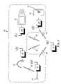
- Each of the devices 30 - 37also includes piconet RF interface 38 and/or wireless interface 39 .
- Piconet RF interface 38may be constructed to support one or more versions of the Bluetooth specification.
- each of the piconet RF interfaces 38 - 36include a radio frequency transceiver that operates at 2.4 gigahertz and baseband processing for modulating and demodulating data that is transceived within a piconet.
- wireless headset 10may be wirelessly coupled with any one of the devices 30 - 37 and act as the headset communicatively coupled and registered to the devices 30 - 37 .
- Devices 30 - 37may further include a wireless LAN (WLAN) RF interface 39 .
- the wireless LAN RF interfaces 39may be constructed in accordance with one or more versions of IEEE802.11 (a), (b), and/or (g) or other WLAN protocol known to those skilled in the art. Accordingly, each of the WLAN RF interfaces 39 include an RF transceiver that may operate in the 2.4 gigahertz range and/or in the 5.25 or 5.75 gigahertz range and further includes baseband processing to modulate and demodulate data that is transceived over the corresponding wireless communication link.
- piconet RF interfacesallow point-to-point communication between the associated devices, while the WLAN RF interfaces enable the associated devices to communicate indirectly via base units.
- laptop 34can communicate directly with cellular telephone 36 .
- WLAN RF interfaces 39laptop 34 communicates indirectly, via access point 21 , with cellular telephone 36 .
- the coverage area of a piconetis significantly smaller than the coverage area of a WLAN.
- headset 10 and cellular telephone 36were unable to establish a piconet connection via piconet RF interfaces 38 due to distance between the devices. These devices would be able to establish a wireless communication link via the WLAN RF interfaces 39 and access point 21 .
- Dual communication pathwaysallow communications to be switched between pathways, dependent on factors such as audio quality, signal strength, and available bandwidth.
- Wireless headset 10may establish a piconet with any one of the devices 30 - 37 or with access point 21 , which includes WLAN RF interface 39 and piconet RF interface 38 .
- wireless headset 10may function as the headset for wire line telephone 37 , Ethernet telephone 35 , personal digital assistant 30 , personal computer 32 , laptop computer 34 and/or cellular telephone 36 provided a piconet and registration can be established with the device.
- an extended networkmay be created utilizing the WLAN connectivity and at least one corresponding piconet.
- the piconet RF interfaces of cellular telephone 36 and headset 10would establish a piconet, which may be established in accordance with the Bluetooth specification.
- cellular telephone 36via its WLAN RF interface, establishes a wireless connection with access point 21 .
- Access point 21then establishes a communication link with wire line telephone 37 .
- headset 10may be directly coupled to LAN 50 or coupled to a private branch exchange (PBX), which in turn is coupled to access point 21 .
- PBXprivate branch exchange
- the range of headset 10may be extended utilizing the WLAN within the geographic area.
- headset 10extends the mobility of its user, extends the range of headset use and expands on headset functionality while preserving privacy and security by seeking service from base units to which it may be registered.
- headset 10may establish a piconet with cell phone 36 . This allows cell phone 36 to establish an alternate communication pathway for the communications serviced by wired telephone 37 . Then it is possible for the call serviced by telephone 37 or 35 to be “handed off” to cellular telephone 36 .
- FIG. 4is a diagram of another embodiment of a modular wireless headset 10 that includes two earpieces 12 A and 12 B, microphone 14 , and user interface 22 .
- microphone 14communicates with base unit 16 via communication pathway 20
- earpiece 12 Acommunicates with base unit 16 using transceiver (or receiver) 13 A via communication pathway 18
- earpiece 12 Bcommunicates with base unit 16 using transceiver (or receiver) 13 B via communication pathway 32 .
- earpieces 12 A and 12 B, and microphone 14may establish a piconet and communicate with base unit 16 via a single communication pathway.
- voice produced by the individual using microphone 14is received via a microphone transducer and converted into RF signals by circuitry within microphone 14 , as shown in FIG. 7 .
- These RF signalsare provided to base unit 16 via the previously identified communication pathways.
- Base unit 16includes a corresponding receiver antenna 46 and receiver module to recapture the audio signals received via communication pathways 18 , 20 and 32 .
- base unit 16includes at least one transmitter to transmit audio information to the earpiece(s) 12 A and 12 B.
- base unit 16may transmit left channel stereo information to earpiece 12 A and right channel stereo information to earpiece 12 B.
- microphone 14may also receive voice commands that are recognized and executed by processing modules within the modular headset. The processing of these commands will be discussed in further detail with reference to FIG. 7 .
- Wireless headphone(s)may be realized by omitting microphone 14 and including either one or both of earpieces 12 A and 12 B.
- base unit 16may be a playback device such as a CD player, DVD player, cassette player, etc. operable to stream audio information. If the display of FIG. 2 is utilized as well, both streaming audio and video may be enjoyed by the user.
- FIG. 5is a diagram of a base unit that supports modular wireless multimedia devices.
- Base unit 16includes a combination of transmitter and receiver (or transceiver) modules that accept and modulate or demodulate streamed audio, video, text, or data to and from earpiece(s) 12 and microphone 14 , display 17 and whiteboard 19 through antenna 46 .
- the base unitmay be incorporated within or operably couple to another device such as a playback device, laptop, cellular telephone, land based telephone or other like device known to those skilled in the art.
- a playback devicesuch as a playback device, laptop, cellular telephone, land based telephone or other like device known to those skilled in the art.
- one embodimenthas transmitter module 40 and receiver module 42 .
- Base unit 16also includes registration circuit 49 with which to compare registration information contained in memory available to base unit 16 and registration information received from headset 10 . Registration may occur by physically coupling or docking headset 10 to the base unit or may occur wirelessly. Registration allows a trusted relationship to be established between base unit 16 and headset 10 . This relationship ensures privacy and security of communication service by the wireless connection between base unit 16 and headset 10 . This trusted relationship utilizes a pass key or other like means of verification to ensure that base unit 16 and headset 10 have permission to access one another. Once the trusted relationship is established through registration, the re-initialization of that relationship is not necessary in order to service communications between base unit 16 and headset 10 .
- the registration information to be exchanged and comparedmay include voice patterns, biometric information, user tactile inputs in response to stimuli, password, voice recognized input, audio or video tests, encryption keys, handwriting recognition inputs, third party verification and testing, proximity information or other like information known to those skilled in the art. This same set of information may also be used in the previously identified paring process.
- Transmitter module 40accepts voice communications or unmodulated streamed audio, video, data or text from a servicing network or playback device 44 (e.g., DVD player, MP3 player, CD player, cassette player, or other like devices known to those skilled in the art). Playback device 44 may be integrated within base unit 16 . Transmitter module 40 then modulates the streamed audio into low intermediate frequency (IF) signal. In the case where two earpieces are employed, multiple transmitter modules or time separation may be employed to modulate the streamed audio into low IF signals for the earpieces for each channel (i.e. left and right channels of stereo transmissions. These multiple signals are synchronized in their presentation to a user.
- IFintermediate frequency
- receiver module 42accepts modulated streamed audio, video, data or text from multimedia device 10 .
- Receiver module 42recovers signals from the received low IF signals. The recovered signals are then relayed to the servicing network or presentation device 45 .
- the generation of low IF signals and subsequent demodulation to recapture audio signalmay be done in accordance with a particular wireless communication standard.
- the Bluetooth specificationmay be used, IEEE802.11 (a), (b), and/or (g) may also be used, etc. when base unit 16 couples to a telephone network (PSTN, cellular, satellite, WLAN, VOIP, etc.).
- Base unit 16may receive data associated with the command as well. For example, caller ID information may be passed to user interface 22 or enhanced call operations may be initiated based on input received at the user interface.
- FIG. 6is a schematic block diagram of earpiece 12 .
- Earpiece 12includes receiver module 41 , optional user interface 43 , processing module 45 and speaker module 47 .
- Receiver module 40includes antenna 46 , bandpass filter 48 , low noise amplifier 50 , down converter 52 and local oscillator 54 .
- User interface 43can be any combinations of a visual interface as evidenced by display 22 , tactile interface as evidenced by buttons 26 , and/or an audio interface represented by microphone/speaker and may operably couple to processing module 58 to initiate call functions or playback functions which will be described further in FIG. 10 .
- Processing module 45performs data recovery and includes an analog-to-digital converter (ADC) 56 .
- the processing modulealso includes pairing circuit 49 and registration circuit 51 .
- Digital channel filter 60 and demodulator 61process the recovered signal while setup module 76 , pairing circuit 49 and registration circuit 51 act to establish secure, private communications path with trusted devices and the base units.
- Speaker module 47includes a digital-to-analog converter (DAC) 62 , variable gain module 64 , and at least one speaker 66 to render recovered communications.
- DACdigital-to-analog converter
- receiver module 41receives inbound RF signal 68 from base unit 16 via antenna 46 .
- Bandpass filter 48filters the received RF signal 68 which are subsequently amplified by low noise amplifier 50 .
- Down converter 52converts the filtered and amplified RF signal 68 into low intermediate frequency (IF) signal 70 based on a local oscillator 54 .
- Low IF signals 70may have a carrier frequency at DC ranging to a few megahertz.
- Processing module 45receives low IF signals 70 and converts the low IF signals 70 into digital signals via ADC 56 .
- Processing module 45may be a single processing device or a plurality of processing devices.
- Such a processing devicemay be a microprocessor, micro-controller, digital signal processor, microcomputer, central processing unit, field programmable gate array, programmable logic device, state machine, logic circuitry, analog circuitry, digital circuitry, and/or any device that manipulates signals (analog and/or digital) based on operational instructions.
- the memory(not shown) may be a single memory device or a plurality of memory devices.
- Such a memory devicemay be a read-only memory, random access memory, volatile memory, non-volatile memory, static memory, dynamic memory, flash memory, and/or any device that stores digital information.
- processing module 58implements one or more of its functions via a state machine, analog circuitry, digital circuitry, and/or logic circuitry
- the memory storing the corresponding operational instructionsis embedded with the circuitry comprising the state machine, analog circuitry, digital circuitry, and/or logic circuitry.
- Digital channel filter 60receives the digital low IF signals 72 and filters these signals.
- Demodulator 61recovers audio signals 74 from the filtered low IF signals.
- the generation of RF signal 68 and subsequent demodulation to recapture audio signal 74may be done in accordance with a particular wireless communication standard.
- the Bluetooth specificationmay be used; IEEE802.11 (a), (b), and/or (g) may also be used, etc.
- Speaker module 47converts digital audio signal 72 into analog signals rendered to the user through speakers 66 .
- Adjustable gain module 64adjusts the gain (i.e., adjusts volume), and provides the amplified signals to speaker 66 , which produces audible signals 74 . As long as the piconet remains in place between earpiece 12 and base unit 16 , earpiece 12 will produce audible signals 74 from received inbound RF signal 68 .
- FIG. 7is a schematic block diagram of microphone 14 that includes audio input module 80 , transmitter module 82 and user interface 101 .
- Audio input module 80includes microphone 84 , amplifier 86 , ADC 88 , processing module 100 that includes a setup module 92 and modulator 90 , and DAC 62 .
- Setup module 92further includes a pairing circuit and an optional registration circuit to establish secure, private communications as previously described.
- User interface 101can be any combinations of a visual interface as evidenced by display 103 , tactile interface as evidenced by buttons 107 , and/or an audio interface represented by microphone/speaker 109 and may operably couple to processing module 100 to initiate call functions which will be described further in FIG. 10 .
- Transmitter module 82includes up-converter 94 , local oscillator 96 , power amplifier 97 , bandpass filter 98 , and antenna 102 .
- ADC 88couples to microphone 84 where ADC 88 can produce a digital audio signal from the analog audio signals captured by the microphone.
- Multiple CODECsmay be used.
- a voice recognition software (VRS) codecmay be used when the ADC operates in a voice command mode.
- a voice codec that supports voice communicationsmay be used when the ADC is operating in a voice mode. The user may be able to select in the voice command mode with a one-touch button or other user interface causing the ADC to utilize a separate codec for the voice command mode.
- ADC 88may be located either in microphone 14 or within earpiece 12 .
- ADC 88may in fact be two or more ADCs that are coupled to the microphone transducer.
- the first ADCwould be operable to produce digital audio signals from the analog audio signals captured by the microphone in accordance with the VRS CODEC.
- the second ADCoperating in parallel with the first supports voice communications with a separate voice codec.
- These ADCsmay be contained or coupled to processing module 100 .
- voice commandsmay be used to implement many functions. These functions may include, but are not limited to, network interface functions, base unit interface functions, directory functions, caller I.D. functions, call waiting functions, call conferencing functions, call initiation functions, device programming functions, and playback device functions. Additionally, the user voice commands may be used to initiate, validate, and/or authenticate a servicing network and the formation of a trusted relationship between modular components such as microphone 14 and earpiece 12 .
- microphone 14is configured within a piconet
- microphone 84to receives audio signals 105 and converts these signals to analog signals 106 .
- Amplifier 86amplifies analog audio signals 106 that ADC 88 then converts into digital audio signals 108 .
- Modulator 90modulates the digital signals based on a predetermined communication standard. As shown, modulator 90 and setup module 92 are implemented within processing module 100 .
- Processing module 100may be a single processing device or a plurality of processing devices.
- Such a processing devicemay be a microprocessor, micro-controller, digital signal processor, microcomputer, central processing unit, field programmable gate array, programmable logic device, state machine, logic circuitry, analog circuitry, digital circuitry, and/or any device that manipulates signals (analog and/or digital) based on operational instructions.
- the memorymay be a single memory device or a plurality of memory devices.
- Such a memory devicemay be a read-only memory, random access memory, volatile memory, non-volatile memory, static memory, dynamic memory, flash memory, and/or any device that stores digital information.
- processing module 100implements one or more of its functions via a state machine, analog circuitry, digital circuitry, and/or logic circuitry
- the memory storing the corresponding operational instructionsis embedded with the circuitry comprising the state machine, analog circuitry, digital circuitry, and/or logic circuitry.
- Up-converter 94converts modulated signals 110 into RF signals based on local oscillator 96 .
- Power amplifier 97amplifies these signals which may be subsequently processed by bandpass filter 98 .
- the filtered RF signalsare then transmitted via antenna 102 as outbound RF signals 110 to base unit 16 .
- the piconetis established to include microphone 14 and base unit 16 in a trusted pair, microphone 14 may transmit to base unit 16 in the manner described.
- separable connector 112may physically connect setup modules 76 and 92 .
- Such a physical connectionallows for earpiece 12 and microphone 14 to communicate in both directions with the base unit.
- base unit 16functioning as the master, may issue a registration request to earpiece 12 coupled to microphone 14 .
- earpiece 12 and microphone 14respond to the request indicating that RF channel(s) be established for the headset.
- the mastercoordinates the establishment of the pathways and provides synchronization information through earpiece 12 and microphone 14 via receiver module 40 of earpiece 12 .
- Setup modules 76 and 92coordinate the registration of earpiece 12 and microphone 14 with the base unit, pairing of earpiece 12 and microphone 14 , as well as coordinating timeslot assignments and/or SCO link assignments. Once the physical connection between earpiece 12 and microphone may be severed to establish earpiece 12 and microphone 14 as separate pieces.
- earpiece 12 and microphone 14may each directly couple to the base unit to accomplish this setup.
- FIGS. 8 and 9illustrate schematic block diagrams of earpiece 12 and microphone 14 that include transceiver modules (i.e., receiver modules and transmitter modules).
- transceiver modulesi.e., receiver modules and transmitter modules.
- the use of the transceiver modulesallow earpiece 12 , microphone 14 and base unit 16 to be physically separate devices and be configured, paired and registered using wireless communications. As such, earpiece 12 and microphone 14 may be continuously worn on a person for receiving incoming calls and/or placing outgoing calls.
- Earpiece 12includes antenna 46 , transmit/receive switch 122 , receiver module 41 , processing module 45 , speaker module 47 , transmitter module 120 , input module 128 and display module 132 .
- Receiver module 41 , processing module 45 and speaker module 47operate as discussed with reference to FIG. 6 .
- Processing module 45may also produce display information for display module 132 .
- the received RF signalmay include information such as caller ID, command information, etc. which is separated by processing module 45 and provided to display module 132 , which may be an LCD display, plasma display, etc.
- Input module 128which may be a keypad, touch screen, voice recognition circuit, or other like user interfaces, receives user commands and produces digital command messages 124 there from.
- digital command messages 124includes, but are not limited to, packet size, synchronization information, frequency hopping initiation information, timeslot allocation information, link establishment information, piconet address information, fast-forward, play, pause, volume adjust, record, stop and rewind.
- Processing module 45receives digital command messages 124 and, when applicable, processes the command messages. For example, if the command message is with respect to a volume adjust; a graphical representation of adjusting the volume may be presented on display module 132 and the gain of amplifier 64 adjusted to adjust the volume associated with speaker 66 . This command may also initiate pairing and registration.
- Transmit module 120receives digital command messages 124 and converts these messages into outbound RF command signals 126 , which are subsequently transmitted to base unit 16 and/or microphone module via antenna 46 . Accordingly, by including transmitter module 120 along with receiver module 41 , earpiece 12 may function as a master and/or slave and exchange/relay data for other components.
- FIG. 9is a schematic block diagram of microphone 14 that includes audio input module 80 , transmitter module 82 , transmit receive switch 122 , antenna 102 , receiver module 132 , input module 140 and display module 138 .
- Input module 140is operable to receive user input commands 142 , including voice commands and convert these commands into digital command messages 144 .
- the combination of audio input module 80 and input module 140include one or more ADCs, such as previously described ADC 88 operable to processed transduced audio communications with a voice CODEC and voice commands with a voice recognition software (VRS) CODEC.
- ADCssuch as previously described ADC 88 operable to processed transduced audio communications with a voice CODEC and voice commands with a voice recognition software (VRS) CODEC.
- Input module 140couples to or includes a user interface that allows a user to initiate call functions or network hardware operations, such as pairing and registration.
- Network interface functionsmay include base unit interface functions, component interface functions, directory functions, caller ID functions, voice activated commands and device programming functions.
- This user interfacecan be any combinations of visual interface(s), tactile interface(s), and/or an audio interface(s) that allow the user to input commands 142 .
- Digital command messages 144may be similar to digital command messages 124 and may further include establish a call, terminate a call, call waiting, or other like functions.
- Transmitter module 82converts digital command messages 144 into RF command signals 134 that are transmitted via antenna 102 . Similarly, inbound RF command signals 135 may be received by receiver module 132 via antenna 102 .
- Display module 138which may be a LCD display, plasma display, etc., receives digital command messages 136 and may display corresponding configuration messages. In addition, any display information received from the host and/or microphone module regarding setup, operation, or as part of the data content, may be displayed on display module 138 .
- FIG. 10is a logic diagram illustrating operation of a wireless headset constructed according to the present invention in serving voice communications while providing call management.
- the operations described with reference to FIG. 10may be performed whole or in part by an on-chip processor within or coupled to processing modules 58 and 100 of FIGS. 6 and 7 .
- the wireless headsetservices normal operations, e.g., single call or device playback.
- Other modular devicessuch as those of FIG. 2 that couple to the microphone or headset, may perform these operations.
- These functionsmay be implemented by voice commands recognized by the VRS CODEC as discussed with reference to FIGS. 7 and 9 .
- step 1004One particular operation that the wireless headset may perform is to place a call on hold (step 1004 ). In such case, the wireless headset ceases producing audio input and audio output for the call (step 1006 ). These operations are continued during a wait state (step 1008 ) until normal operations are resumed for the call (step 1010 ). From step 1010 , operation proceeds to step 1002 .
- the call hold operations of steps 1004 - 1010may be performed in conjunction with the other operations of FIG. 10 , e.g., call waiting, call muting, call conferencing, etc.
- Call conferencingmay be initiated by the wireless headset or by a master device if the wireless headset does not have sufficient user interface for call conferencing initiation.
- a new callis established by the wireless headset (step 1014 ).
- This new callmay be serviced by the additional channels serviced by the wireless headset.
- the wireless headsetsupports multiple channels. Using this multiple channels, the wireless headset receives audio input from all participants (step 1016 ) and combines the audio input, along with the input generated by the user of the wireless headset. The wireless headset then directs the combined audio to all participants (their servicing CODECs at step 1020 ). Note that these operations are continually performed for the duration of the conference call.
- the wireless headsetmay also mute calls (step 1022 ). In such case, the wireless headset simply ceases all audio output ( 1024 ) and waits for the user of the wireless headset to cease the muting operations (step 1026 ). When the muting has been ceased, the wireless headset resumes the audio servicing of the call (step 1028 ).
- the wireless multimedia devicealso performs call waiting operations (step 1030 ). In such case, the wireless multimedia device receives an indication that a call is inbound (step 1032 ). However, instead of immediately servicing the call, the wireless multimedia device notifies the user of the wireless multimedia device of the call (step 1034 ), e.g., provides a beeping indication to the user of the wireless multimedia device. The wireless multimedia device then services the call (step 1036 ), at the direction of the user to either complete the call, have the call join a currently serviced call (via call conferencing operations in some cases), or to ignore the call.
- the wireless multimedia devicemay also perform call forwarding operations according to the present invention (step 1038 ). In such case, the wireless multimedia device receives the call (step 1040 ). However, instead of servicing the call, the wireless multimedia device determines a forwarding location for the call (step 1042 ) and then forwards the call (step 1044 ). Operation from steps 1010 , 1020 , 1028 , 1036 , and 1044 return to step 1002 .
- FIG. 11is a schematic block diagram of modular communication device 150 , such as a wireless terminal (e.g., cell phone or wireless packet data phone) that includes host device (base unit) 152 , detachable microphone 154 and detachable earpiece 156 .
- modular communication device 150may function as a typical device (e.g., cellular telephone, CD player, cassette player, etc.) when detachable earpiece 156 and detachable microphone 154 are physically connected to host device 152 .
- a wireless connectioncouples detachable earpiece 156 and host device 152 .
- modular communication device 150may include multiple detachable earpieces 156 .
- modular communication device 150may omit detachable microphone 154 if host device 152 is a playback type device (e.g., DVD player, CD player, cassette player, etc.).
- modular communication device 150may omit detachable earpiece 156 when functioning as a recording device (e.g., dictaphone).
- Detachable earpiece 156 and microphone 154may have on-chip operations to support call conferencing, call waiting, flash, and other features associated with telephones. These functions may be accessed and reviewed by a user interface 158 and display 160 within host device 152 or a user interface and display located on either detachable earpiece 156 or microphone 154 .
- the user interface and display, located on either the host device or detachable earpiece 156 and microphone 154may have a display and button(s) that may be used to program device, perform directory functions including selecting number to call, view caller ID, initiate call waiting, or initiate call conferencing.
- circuitry within the earpiece 156 and microphone 154may enable voice activated dialing.
- the actual voice recognitioncould be performed within earpiece 156 , microphone 154 , or host device 152 .
- earpiece 156 and microphone 154may act to initiate calls and receive calls.
- a link between earpiece 156 and microphone 154would allow earpiece 156 and microphone 154 to share resources, such as battery life, and allow earpiece 156 and microphone 154 to be recharged from host device 152 .
- Earpiece/microphone/base portionare included with cell phone battery.
- Cell phone batteryhas openings 162 and 164 located therein for storage/recharging of earpiece 156 and microphone 154 . When located in these openings, the earpiece/microphone will be recharged from the cell phone battery.
- the new cell phone batterymay include base portion RF interface and interface to cell phone port. Existing cell phone port technology could be used to treat the earpiece/microphone in the same manner as wired earpiece/microphone is treated.
- FIG. 12is a logic flow diagram of a method of servicing voice communications between a destination terminal and modular wireless headset.
- audio information from the useris received through a microphone as described previously with reference to microphone 14 .
- This audio informationis received in step 200 .
- a usermay activate a voice command mode with a one-touch button or other like interface known to those having skill in the art.
- a determinationis made as to whether or not a voice command mode is active or selected. If the voice command mode is not active normal operations and servicing of the audio communications will continue utilizing a voice CODECs in step 204 .
- ADCs utilizing a VRS CODECwill convert the voice commands, audio communications received through the microphone, into digital commands in step 206 . These digital commands are used in step 208 to initiate specific functions such as enhanced call features, equipment features, network functions or other like features.
- FIG. 13provides a second logic flow diagram, however, in this case multiple ADCs are present wherein each ADC is operable to process received audio information.
- audio informationis received by the multiple ADCs.
- a first ADCmay process the audio information with a VRS CODEC in step 302 then a determination may be made at decision point 304 as to whether or not a voice command is present within the processed audio information. If not, the audio information may be processed using a voice CODEC in step 306 and the call for other audio communications will continue to be normally serviced. Should a voice command be present as determined at step 304 , the voice command will be converted into a digital command in step 308 , after which the digital command may be initiated in step 310 . Although described as occurring in series in FIG. 13 , the processing by the multiple ADCs utilizing multiple CODECs may occur in parallel.
- the present inventionprovides a modular headset operable to support both voice communications and voice activated commands. This may involve the use of multiple voice CODECs to process voice communications and voice activated commands.
- the modular headsetincludes both a microphone and wireless earpiece.
- the earpiecemay further include an interface, a processing circuit, a speaker, a user interface, a pairing circuit, and a registration circuit.
- the interfaceallows the earpiece to communicate with the base unit that couples the modular headset to a servicing network.
- One or more analog to digital converters (ADCs)which may be located within either the microphone or earpiece, are operable to process the transduced voice communications in accordance with either a voice CODEC and/or voice recognition CODEC depending on the selected mode of operation or the processing architecture.
- the term “substantially” or “approximately”, as may be used herein,provides an industry-accepted tolerance to its corresponding term. Such an industry-accepted tolerance ranges from less than one percent to twenty percent and corresponds to, but is not limited to, component values, integrated circuit process variations, temperature variations, rise and fall times, and/or thermal noise.
- the term “operably coupled”, as may be used herein,includes direct coupling and indirect coupling via another component, element, circuit, or module where, for indirect coupling, the intervening component, element, circuit, or module does not modify the information of a signal but may adjust its current level, voltage level, and/or power level.
- inferred couplingincludes direct and indirect coupling between two elements in the same manner as “operably coupled”.
- the term “compares favorably”, as may be used herein,indicates that a comparison between two or more elements, items, signals, etc., provides a desired relationship. For example, when the desired relationship is that signal 1 has a greater magnitude than signal 2 , a favorable comparison may be achieved when the magnitude of signal 1 is greater than that of signal 2 or when the magnitude of signal 2 is less than that of signal 1 .
Landscapes
- Engineering & Computer Science (AREA)
- Signal Processing (AREA)
- Computer Networks & Wireless Communication (AREA)
- Health & Medical Sciences (AREA)
- Otolaryngology (AREA)
- Telephone Function (AREA)
Abstract
Description
Claims (26)
Priority Applications (3)
| Application Number | Priority Date | Filing Date | Title |
|---|---|---|---|
| US11/120,900US7343177B2 (en) | 2005-05-03 | 2005-05-03 | Modular ear-piece/microphone (headset) operable to service voice activated commands |
| US11/932,362US20080058023A1 (en) | 2005-05-03 | 2007-10-31 | Modular ear-piece/microphone (headset) operable to service voice activated commands |
| US12/343,846US8116823B2 (en) | 2005-05-03 | 2008-12-24 | Modular ear-piece/microphone (headset) operable to service voice activated commands |
Applications Claiming Priority (1)
| Application Number | Priority Date | Filing Date | Title |
|---|---|---|---|
| US11/120,900US7343177B2 (en) | 2005-05-03 | 2005-05-03 | Modular ear-piece/microphone (headset) operable to service voice activated commands |
Related Child Applications (1)
| Application Number | Title | Priority Date | Filing Date |
|---|---|---|---|
| US11/932,362ContinuationUS20080058023A1 (en) | 2005-05-03 | 2007-10-31 | Modular ear-piece/microphone (headset) operable to service voice activated commands |
Publications (2)
| Publication Number | Publication Date |
|---|---|
| US20060252470A1 US20060252470A1 (en) | 2006-11-09 |
| US7343177B2true US7343177B2 (en) | 2008-03-11 |
Family
ID=37394641
Family Applications (3)
| Application Number | Title | Priority Date | Filing Date |
|---|---|---|---|
| US11/120,900Expired - Fee RelatedUS7343177B2 (en) | 2005-05-03 | 2005-05-03 | Modular ear-piece/microphone (headset) operable to service voice activated commands |
| US11/932,362AbandonedUS20080058023A1 (en) | 2005-05-03 | 2007-10-31 | Modular ear-piece/microphone (headset) operable to service voice activated commands |
| US12/343,846Expired - Fee RelatedUS8116823B2 (en) | 2005-05-03 | 2008-12-24 | Modular ear-piece/microphone (headset) operable to service voice activated commands |
Family Applications After (2)
| Application Number | Title | Priority Date | Filing Date |
|---|---|---|---|
| US11/932,362AbandonedUS20080058023A1 (en) | 2005-05-03 | 2007-10-31 | Modular ear-piece/microphone (headset) operable to service voice activated commands |
| US12/343,846Expired - Fee RelatedUS8116823B2 (en) | 2005-05-03 | 2008-12-24 | Modular ear-piece/microphone (headset) operable to service voice activated commands |
Country Status (1)
| Country | Link |
|---|---|
| US (3) | US7343177B2 (en) |
Cited By (23)
| Publication number | Priority date | Publication date | Assignee | Title |
|---|---|---|---|---|
| US20060166718A1 (en)* | 2005-01-24 | 2006-07-27 | Nambirajan Seshadri | Pairing modular wireless earpiece/microphone (HEADSET) to a serviced base portion and subsequent access thereto |
| US20060294262A1 (en)* | 2005-06-22 | 2006-12-28 | Airus Technology Co., Ltd. | Portable VOIP wireless connector |
| US20070016344A1 (en)* | 2005-07-15 | 2007-01-18 | Arinc, Incorporated | Systems and methods for voice communications and control using adapted portable data storage and display devices |
| US20070143105A1 (en)* | 2005-12-16 | 2007-06-21 | Keith Braho | Wireless headset and method for robust voice data communication |
| US20070260236A1 (en)* | 2006-04-14 | 2007-11-08 | Samsung Electronics Co., Ltd. | Radio frequency communication devices using chaotic signal and method thereof |
| US20080242328A1 (en)* | 2007-03-29 | 2008-10-02 | Echostar Satellite Llc | Broadcast communication system and method for providing users with information associated with a geographical area |
| US20090325650A1 (en)* | 2005-02-15 | 2009-12-31 | Broadcom Corporation | Handover of call serviced by modular ear-piece/microphone between servicing base portions |
| US7738434B1 (en)* | 2002-03-04 | 2010-06-15 | Plantronics, Inc. | Control and management of a wired or wireless headset |
| USD619124S1 (en) | 2009-08-07 | 2010-07-06 | Ansr Audio | Wireless ear worn microphone transmitter |
| US20100296444A1 (en)* | 2009-05-22 | 2010-11-25 | Raytheon Company | System and Method for Providing Voice Communications Over a Multi-Level Secure Network |
| US20110107415A1 (en)* | 2009-11-05 | 2011-05-05 | Yangmin Shen | Portable computing device and headset interface |
| US20110124321A1 (en)* | 2009-11-23 | 2011-05-26 | Samsung Electronics Co. Ltd. | Apparatus and method for changing communication mode in mobile terminal |
| US8842849B2 (en) | 2006-02-06 | 2014-09-23 | Vocollect, Inc. | Headset terminal with speech functionality |
| US20140350943A1 (en)* | 2006-07-08 | 2014-11-27 | Personics Holdings, LLC. | Personal audio assistant device and method |
| US8930647B1 (en) | 2011-04-06 | 2015-01-06 | P4tents1, LLC | Multiple class memory systems |
| US9158546B1 (en) | 2011-04-06 | 2015-10-13 | P4tents1, LLC | Computer program product for fetching from a first physical memory between an execution of a plurality of threads associated with a second physical memory |
| US9164679B2 (en) | 2011-04-06 | 2015-10-20 | Patents1, Llc | System, method and computer program product for multi-thread operation involving first memory of a first memory class and second memory of a second memory class |
| US9170744B1 (en) | 2011-04-06 | 2015-10-27 | P4tents1, LLC | Computer program product for controlling a flash/DRAM/embedded DRAM-equipped system |
| US9176671B1 (en) | 2011-04-06 | 2015-11-03 | P4tents1, LLC | Fetching data between thread execution in a flash/DRAM/embedded DRAM-equipped system |
| US9417754B2 (en) | 2011-08-05 | 2016-08-16 | P4tents1, LLC | User interface system, method, and computer program product |
| US20190159001A1 (en)* | 2016-05-04 | 2019-05-23 | D & L High-Tech Corporation Limited | Bluetooth microphone |
| US11425485B2 (en) | 2008-04-07 | 2022-08-23 | Koss Corporation | Wireless earphone that transitions between wireless networks |
| US11450331B2 (en) | 2006-07-08 | 2022-09-20 | Staton Techiya, Llc | Personal audio assistant device and method |
Families Citing this family (76)
| Publication number | Priority date | Publication date | Assignee | Title |
|---|---|---|---|---|
| US8204435B2 (en)* | 2003-05-28 | 2012-06-19 | Broadcom Corporation | Wireless headset supporting enhanced call functions |
| US20060166717A1 (en)* | 2005-01-24 | 2006-07-27 | Nambirajan Seshadri | Managing access of modular wireless earpiece/microphone (HEADSET) to public/private servicing base station |
| US7558529B2 (en)* | 2005-01-24 | 2009-07-07 | Broadcom Corporation | Earpiece/microphone (headset) servicing multiple incoming audio streams |
| US7931537B2 (en)* | 2005-06-24 | 2011-04-26 | Microsoft Corporation | Voice input in a multimedia console environment |
| US8087936B2 (en)* | 2005-10-03 | 2012-01-03 | Jason Knable | Systems and methods for verbal communication from a speech impaired individual |
| WO2007064735A2 (en)* | 2005-11-29 | 2007-06-07 | Ll International Shoe Company, Inc. | Data system for an article of footwear |
| US8073152B1 (en)* | 2006-06-12 | 2011-12-06 | Plantronics, Inc. | Automated voice over internet protocol wireless headset |
| US8006002B2 (en)* | 2006-12-12 | 2011-08-23 | Apple Inc. | Methods and systems for automatic configuration of peripherals |
| US8031164B2 (en) | 2007-01-05 | 2011-10-04 | Apple Inc. | Backlight and ambient light sensor system |
| US8698727B2 (en) | 2007-01-05 | 2014-04-15 | Apple Inc. | Backlight and ambient light sensor system |
| US8438322B2 (en)* | 2007-01-31 | 2013-05-07 | Broadcom Corporation | Processing module with millimeter wave transceiver interconnection |
| US9486703B2 (en)* | 2007-01-31 | 2016-11-08 | Broadcom Corporation | Mobile communication device with game application for use in conjunction with a remote mobile communication device and methods for use therewith |
| US20090011832A1 (en)* | 2007-01-31 | 2009-01-08 | Broadcom Corporation | Mobile communication device with game application for display on a remote monitor and methods for use therewith |
| US8116294B2 (en)* | 2007-01-31 | 2012-02-14 | Broadcom Corporation | RF bus controller |
| US8254319B2 (en)* | 2007-01-31 | 2012-08-28 | Broadcom Corporation | Wireless programmable logic device |
| US8239650B2 (en)* | 2007-01-31 | 2012-08-07 | Broadcom Corporation | Wirelessly configurable memory device addressing |
| US8200156B2 (en)* | 2007-01-31 | 2012-06-12 | Broadcom Corporation | Apparatus for allocation of wireless resources |
| US20080320293A1 (en)* | 2007-01-31 | 2008-12-25 | Broadcom Corporation | Configurable processing core |
| US8121541B2 (en)* | 2007-01-31 | 2012-02-21 | Broadcom Corporation | Integrated circuit with intra-chip and extra-chip RF communication |
| US8223736B2 (en)* | 2007-01-31 | 2012-07-17 | Broadcom Corporation | Apparatus for managing frequency use |
| US8289944B2 (en)* | 2007-01-31 | 2012-10-16 | Broadcom Corporation | Apparatus for configuration of wireless operation |
| US8238275B2 (en)* | 2007-01-31 | 2012-08-07 | Broadcom Corporation | IC with MMW transceiver communications |
| US8280303B2 (en)* | 2007-01-31 | 2012-10-02 | Broadcom Corporation | Distributed digital signal processor |
| US8204075B2 (en)* | 2007-01-31 | 2012-06-19 | Broadcom Corporation | Inter-device wireless communication for intra-device communications |
| US20090197641A1 (en)* | 2008-02-06 | 2009-08-06 | Broadcom Corporation | Computing device with handheld and extended computing units |
| US8125950B2 (en)* | 2007-01-31 | 2012-02-28 | Broadcom Corporation | Apparatus for wirelessly managing resources |
| US20090017910A1 (en)* | 2007-06-22 | 2009-01-15 | Broadcom Corporation | Position and motion tracking of an object |
| US20080192951A1 (en)* | 2007-02-08 | 2008-08-14 | Edward Moura | Spectator broadcast system with an ear mounted receiver |
| US8693877B2 (en) | 2007-03-09 | 2014-04-08 | Apple Inc. | Integrated infrared receiver and emitter for multiple functionalities |
| US8155663B2 (en)* | 2007-04-13 | 2012-04-10 | Tessera, Inc. | Wearable ultra-thin miniaturized mobile communications |
| US8254605B2 (en)* | 2007-05-29 | 2012-08-28 | Livescribe, Inc. | Binaural recording for smart pen computing systems |
| US8284951B2 (en)* | 2007-05-29 | 2012-10-09 | Livescribe, Inc. | Enhanced audio recording for smart pen computing systems |
| US8972739B1 (en)* | 2007-06-01 | 2015-03-03 | Plantronics, Inc. | Methods and systems for secure pass-set entry in an I/O device |
| US20120034936A1 (en)* | 2007-08-02 | 2012-02-09 | Sure Best Limited | Associated communication apparatus |
| US8340058B2 (en)* | 2007-10-29 | 2012-12-25 | Nvidia Corporation | Headphone with enhanced voice communication |
| US8175646B2 (en)* | 2008-02-06 | 2012-05-08 | Broadcom Corporation | Networking of multiple mode handheld computing unit |
| US8195928B2 (en)* | 2008-02-06 | 2012-06-05 | Broadcom Corporation | Handheld computing unit with merged mode |
| US8117370B2 (en)* | 2008-02-06 | 2012-02-14 | Broadcom Corporation | IC for handheld computing unit of a computing device |
| US8717974B2 (en)* | 2008-02-06 | 2014-05-06 | Broadcom Corporation | Handheld computing unit coordination of femtocell AP functions |
| US20090198798A1 (en)* | 2008-02-06 | 2009-08-06 | Broadcom Corporation | Handheld computing unit back-up system |
| US8064952B2 (en)* | 2008-02-06 | 2011-11-22 | Broadcom Corporation | A/V control for a computing device with handheld and extended computing units |
| US9113240B2 (en)* | 2008-03-18 | 2015-08-18 | Qualcomm Incorporated | Speech enhancement using multiple microphones on multiple devices |
| US8355515B2 (en)* | 2008-04-07 | 2013-01-15 | Sony Computer Entertainment Inc. | Gaming headset and charging method |
| US8430750B2 (en)* | 2008-05-22 | 2013-04-30 | Broadcom Corporation | Video gaming device with image identification |
| DE102008031407A1 (en)* | 2008-07-02 | 2010-01-14 | Enocean Gmbh | Initialization procedure and operating procedure for a radio network |
| US8498425B2 (en)* | 2008-08-13 | 2013-07-30 | Onvocal Inc | Wearable headset with self-contained vocal feedback and vocal command |
| US8825015B2 (en)* | 2008-09-18 | 2014-09-02 | Nvidia Corporation | Accessing web pages on communication paths with low bandwidth |
| US20110306393A1 (en) | 2010-06-15 | 2011-12-15 | Tomasz Goldman | Headset base with display and communications base |
| US8838029B2 (en)* | 2009-01-20 | 2014-09-16 | Gn Netcom A/S | Headset system with two user interfaces |
| US8571151B2 (en)* | 2009-03-18 | 2013-10-29 | Qualcomm Incorporated | Emulation of N-bits uniform quantizer from multiple incoherent and noisy one-bit measurements |
| US8965282B2 (en)* | 2009-03-18 | 2015-02-24 | Qualcomm Incorporated | Finite rate of innovation (FRI) techniques for low power body area network (LP-BAN) communications |
| US8625817B2 (en)* | 2009-03-18 | 2014-01-07 | Qualcomm Incorporated | Faster cadzow denoising based on partial eigenvalue decomposition |
| US8724686B2 (en)* | 2009-03-18 | 2014-05-13 | Qualcomm Incorporated | Equalization by the pulse shape inverse of the input to the FRI processing in pulse based communications |
| CA2729983C (en) | 2009-04-24 | 2016-07-26 | Skullcandy, Inc. | Wireless synchronization mechanism |
| US20110280414A1 (en)* | 2010-04-09 | 2011-11-17 | Virginia Johanna Intelisano | Fuzzy woofies: one-way communication between two wireless audio headphone communication systems receiving audio from an audio source |
| EP2393264B1 (en)* | 2010-06-04 | 2017-05-10 | GN Audio A/S | A headset base with wireless connection to a communication base |
| US8761674B2 (en)* | 2011-02-25 | 2014-06-24 | Timothy R. Beevers | Electronic communication system that mimics natural range and orientation dependence |
| US9148280B2 (en)* | 2011-09-29 | 2015-09-29 | Verizon Patent And Licensing Inc. | Method and system for providing secure, modular multimedia interaction |
| WO2013087099A1 (en) | 2011-12-14 | 2013-06-20 | Gn Netcom A/S | Headset base with holder for mobile communication device |
| US20130328667A1 (en)* | 2012-06-10 | 2013-12-12 | Apple Inc. | Remote interaction with siri |
| US9536528B2 (en)* | 2012-07-03 | 2017-01-03 | Google Inc. | Determining hotword suitability |
| US8964822B2 (en) | 2013-02-21 | 2015-02-24 | Nvidia Corporation | Communication system and method |
| US9167347B1 (en)* | 2013-05-13 | 2015-10-20 | Rose Silberberg | Multi media wireless headphones |
| CN103888615A (en)* | 2014-03-26 | 2014-06-25 | 深圳市欧珀通信软件有限公司 | Base, mobile terminal control system and mobile terminal control method |
| DE102015117057B4 (en) | 2014-10-07 | 2017-07-27 | Sennheiser Electronic Gmbh & Co. Kg | Wireless audio transmission system, in particular wireless microphone system and method for wireless audio transmission |
| KR20160048429A (en)* | 2014-10-24 | 2016-05-04 | 엘지전자 주식회사 | Mobile terminal and method for controlling the same |
| US10368170B2 (en)* | 2015-04-17 | 2019-07-30 | Kyocera Corporation | Smart headset and method of routing service in response to proximity to mobile device |
| US20160381452A1 (en)* | 2015-06-25 | 2016-12-29 | Robert Rodriguez | Stand-alone headphones with digital music player |
| US10289205B1 (en)* | 2015-11-24 | 2019-05-14 | Google Llc | Behind the ear gesture control for a head mountable device |
| US9635161B1 (en)* | 2015-12-07 | 2017-04-25 | Motorola Mobility Llc | Methods, systems, and devices for pairing wireless communication devices |
| TW201724871A (en)* | 2015-12-28 | 2017-07-01 | 鴻海精密工業股份有限公司 | Wireless head and microphone having same |
| US9912798B2 (en) | 2016-03-17 | 2018-03-06 | Sandisk Technologies Llc | Wearable device with receptacle to receive an audio device and method of operating same |
| US10678502B2 (en) | 2016-10-20 | 2020-06-09 | Qualcomm Incorporated | Systems and methods for in-ear control of remote devices |
| US11222060B2 (en) | 2017-06-16 | 2022-01-11 | Hewlett-Packard Development Company, L.P. | Voice assistants with graphical image responses |
| US10531247B2 (en)* | 2017-10-19 | 2020-01-07 | Libre Wireless Technologies Inc. | Internet-of-things devices and related methods for performing in-call interactions |
| US20230008865A1 (en)* | 2021-07-12 | 2023-01-12 | Apple Inc. | Method and system for volume control |
Citations (2)
| Publication number | Priority date | Publication date | Assignee | Title |
|---|---|---|---|---|
| US20040001588A1 (en)* | 2002-06-28 | 2004-01-01 | Hairston Tommy Lee | Headset cellular telephones |
| US6714233B2 (en)* | 2000-06-21 | 2004-03-30 | Seiko Epson Corporation | Mobile video telephone system |
Family Cites Families (5)
| Publication number | Priority date | Publication date | Assignee | Title |
|---|---|---|---|---|
| DE19645259C2 (en) | 1996-11-02 | 2001-02-08 | Juergen Prelle | Device for a mobile phone |
| US6424820B1 (en)* | 1999-04-02 | 2002-07-23 | Interval Research Corporation | Inductively coupled wireless system and method |
| US6952483B2 (en)* | 1999-05-10 | 2005-10-04 | Genisus Systems, Inc. | Voice transmission apparatus with UWB |
| DE10114109A1 (en) | 2001-03-22 | 2002-09-26 | Siemens Ag | Radio headset for mobile telephone uses loudspeaker for reproduction of audio signals received directly from base station of mobile radio network |
| US7110798B2 (en)* | 2002-05-09 | 2006-09-19 | Shary Nassimi | Wireless headset |
- 2005
- 2005-05-03USUS11/120,900patent/US7343177B2/ennot_activeExpired - Fee Related
- 2007
- 2007-10-31USUS11/932,362patent/US20080058023A1/ennot_activeAbandoned
- 2008
- 2008-12-24USUS12/343,846patent/US8116823B2/ennot_activeExpired - Fee Related
Patent Citations (2)
| Publication number | Priority date | Publication date | Assignee | Title |
|---|---|---|---|---|
| US6714233B2 (en)* | 2000-06-21 | 2004-03-30 | Seiko Epson Corporation | Mobile video telephone system |
| US20040001588A1 (en)* | 2002-06-28 | 2004-01-01 | Hairston Tommy Lee | Headset cellular telephones |
Cited By (113)
| Publication number | Priority date | Publication date | Assignee | Title |
|---|---|---|---|---|
| US7738434B1 (en)* | 2002-03-04 | 2010-06-15 | Plantronics, Inc. | Control and management of a wired or wireless headset |
| US20060166718A1 (en)* | 2005-01-24 | 2006-07-27 | Nambirajan Seshadri | Pairing modular wireless earpiece/microphone (HEADSET) to a serviced base portion and subsequent access thereto |
| US7778601B2 (en)* | 2005-01-24 | 2010-08-17 | Broadcom Corporation | Pairing modular wireless earpiece/microphone (HEADSET) to a serviced base portion and subsequent access thereto |
| US8086279B2 (en)* | 2005-02-15 | 2011-12-27 | Broadcom Corporation | Handover of call serviced by modular ear-piece/microphone between servicing base portions |
| US20090325650A1 (en)* | 2005-02-15 | 2009-12-31 | Broadcom Corporation | Handover of call serviced by modular ear-piece/microphone between servicing base portions |
| US20060294262A1 (en)* | 2005-06-22 | 2006-12-28 | Airus Technology Co., Ltd. | Portable VOIP wireless connector |
| US20070016344A1 (en)* | 2005-07-15 | 2007-01-18 | Arinc, Incorporated | Systems and methods for voice communications and control using adapted portable data storage and display devices |
| US8417185B2 (en) | 2005-12-16 | 2013-04-09 | Vocollect, Inc. | Wireless headset and method for robust voice data communication |
| US20070143105A1 (en)* | 2005-12-16 | 2007-06-21 | Keith Braho | Wireless headset and method for robust voice data communication |
| US8842849B2 (en) | 2006-02-06 | 2014-09-23 | Vocollect, Inc. | Headset terminal with speech functionality |
| US20070260236A1 (en)* | 2006-04-14 | 2007-11-08 | Samsung Electronics Co., Ltd. | Radio frequency communication devices using chaotic signal and method thereof |
| US10885927B2 (en) | 2006-07-08 | 2021-01-05 | Staton Techiya, Llc | Personal audio assistant device and method |
| US10236012B2 (en) | 2006-07-08 | 2019-03-19 | Staton Techiya, Llc | Personal audio assistant device and method |
| US10236011B2 (en) | 2006-07-08 | 2019-03-19 | Staton Techiya, Llc | Personal audio assistant device and method |
| US12080312B2 (en) | 2006-07-08 | 2024-09-03 | ST R&DTech LLC | Personal audio assistant device and method |
| US10297265B2 (en) | 2006-07-08 | 2019-05-21 | Staton Techiya, Llc | Personal audio assistant device and method |
| US10311887B2 (en)* | 2006-07-08 | 2019-06-04 | Staton Techiya, Llc | Personal audio assistant device and method |
| US10236013B2 (en) | 2006-07-08 | 2019-03-19 | Staton Techiya, Llc | Personal audio assistant device and method |
| US11450331B2 (en) | 2006-07-08 | 2022-09-20 | Staton Techiya, Llc | Personal audio assistant device and method |
| US20140350943A1 (en)* | 2006-07-08 | 2014-11-27 | Personics Holdings, LLC. | Personal audio assistant device and method |
| US10971167B2 (en) | 2006-07-08 | 2021-04-06 | Staton Techiya, Llc | Personal audio assistant device and method |
| US10629219B2 (en) | 2006-07-08 | 2020-04-21 | Staton Techiya, Llc | Personal audio assistant device and method |
| US10410649B2 (en) | 2006-07-08 | 2019-09-10 | Station Techiya, LLC | Personal audio assistant device and method |
| US20100194984A1 (en)* | 2007-03-29 | 2010-08-05 | Echostar Technologies Llc | Broadcast communication system and method for providing users with information associated with a geographical area |
| US9235981B2 (en) | 2007-03-29 | 2016-01-12 | Echostar Technologies L.L.C. | Broadcast communication system and method for providing users with information associated with a geographical area |
| US20080242328A1 (en)* | 2007-03-29 | 2008-10-02 | Echostar Satellite Llc | Broadcast communication system and method for providing users with information associated with a geographical area |
| US20100199303A1 (en)* | 2007-03-29 | 2010-08-05 | Echostar Technologies Llc | Broadcast communication system and method for providing users with information associated with a geographical area |
| US20110207395A1 (en)* | 2007-03-29 | 2011-08-25 | Echostar Technologies L.L.C. | Broadcast Communication System and Method for Providing Users with Information Associated with a Geographical Area |
| US8412092B2 (en)* | 2007-03-29 | 2013-04-02 | Echostar Technologies L.L.C. | Broadcast communication system and method for providing users with information associated with a geographical area |
| US8041332B2 (en) | 2007-03-29 | 2011-10-18 | Echostar Technologies L.L.C. | Broadcast communication system and method for providing users with information associated with a geographical area |
| US8175513B2 (en)* | 2007-03-29 | 2012-05-08 | Echostar Technologies L.L.C. | Broadcast communication system and method for providing users with information associated with a geographical area |
| US20120208449A1 (en)* | 2007-03-29 | 2012-08-16 | Echostar Technologies L.L.C. | Broadcast communication system and method for providing users with information associated witih a geographical area |
| US7734246B2 (en)* | 2007-03-29 | 2010-06-08 | Echostar Technologies L.L.C. | Broadcast communication system and method for providing users with information associated with a geographical area |
| US11792561B2 (en) | 2008-04-07 | 2023-10-17 | Koss Corporation | Wireless earphones that play lossy compressed streaming audio |
| US11653139B2 (en) | 2008-04-07 | 2023-05-16 | Koss Corporation | Wireless earphones that play lossy compressed streaming audio |
| US11425485B2 (en) | 2008-04-07 | 2022-08-23 | Koss Corporation | Wireless earphone that transitions between wireless networks |
| US11425486B2 (en) | 2008-04-07 | 2022-08-23 | Koss Corporation | Wireless earphone that transitions between wireless networks |
| US11582546B2 (en) | 2008-04-07 | 2023-02-14 | Koss Corporation | Wireless earphones with hanger bars |
| US11606638B2 (en) | 2008-04-07 | 2023-03-14 | Koss Corporation | Wireless earphones with digital signal processors |
| US20100299724A1 (en)* | 2009-05-22 | 2010-11-25 | Raytheon Company | User Interface for Providing Voice Communications Over a Multi-Level Secure Network |
| US9160753B2 (en) | 2009-05-22 | 2015-10-13 | Raytheon Company | Analog voice bridge |
| US20100296507A1 (en)* | 2009-05-22 | 2010-11-25 | Raytheon Company | Analog Voice Bridge |
| US8863270B2 (en) | 2009-05-22 | 2014-10-14 | Raytheon Company | User interface for providing voice communications over a multi-level secure network |
| US8730871B2 (en) | 2009-05-22 | 2014-05-20 | Raytheon Company | System and method for providing voice communications over a multi-level secure network |
| US20100296444A1 (en)* | 2009-05-22 | 2010-11-25 | Raytheon Company | System and Method for Providing Voice Communications Over a Multi-Level Secure Network |
| USD619124S1 (en) | 2009-08-07 | 2010-07-06 | Ansr Audio | Wireless ear worn microphone transmitter |
| US8438659B2 (en) | 2009-11-05 | 2013-05-07 | Vocollect, Inc. | Portable computing device and headset interface |
| US20110107415A1 (en)* | 2009-11-05 | 2011-05-05 | Yangmin Shen | Portable computing device and headset interface |
| US20110124321A1 (en)* | 2009-11-23 | 2011-05-26 | Samsung Electronics Co. Ltd. | Apparatus and method for changing communication mode in mobile terminal |
| US9164679B2 (en) | 2011-04-06 | 2015-10-20 | Patents1, Llc | System, method and computer program product for multi-thread operation involving first memory of a first memory class and second memory of a second memory class |
| US8930647B1 (en) | 2011-04-06 | 2015-01-06 | P4tents1, LLC | Multiple class memory systems |
| US9158546B1 (en) | 2011-04-06 | 2015-10-13 | P4tents1, LLC | Computer program product for fetching from a first physical memory between an execution of a plurality of threads associated with a second physical memory |
| US9170744B1 (en) | 2011-04-06 | 2015-10-27 | P4tents1, LLC | Computer program product for controlling a flash/DRAM/embedded DRAM-equipped system |
| US9223507B1 (en) | 2011-04-06 | 2015-12-29 | P4tents1, LLC | System, method and computer program product for fetching data between an execution of a plurality of threads |
| US9195395B1 (en) | 2011-04-06 | 2015-11-24 | P4tents1, LLC | Flash/DRAM/embedded DRAM-equipped system and method |
| US9189442B1 (en) | 2011-04-06 | 2015-11-17 | P4tents1, LLC | Fetching data between thread execution in a flash/DRAM/embedded DRAM-equipped system |
| US9182914B1 (en) | 2011-04-06 | 2015-11-10 | P4tents1, LLC | System, method and computer program product for multi-thread operation involving first memory of a first memory class and second memory of a second memory class |
| US9176671B1 (en) | 2011-04-06 | 2015-11-03 | P4tents1, LLC | Fetching data between thread execution in a flash/DRAM/embedded DRAM-equipped system |
| US10222892B1 (en) | 2011-08-05 | 2019-03-05 | P4tents1, LLC | System, method, and computer program product for a multi-pressure selection touch screen |
| US10222894B1 (en) | 2011-08-05 | 2019-03-05 | P4tents1, LLC | System, method, and computer program product for a multi-pressure selection touch screen |
| US10275087B1 (en) | 2011-08-05 | 2019-04-30 | P4tents1, LLC | Devices, methods, and graphical user interfaces for manipulating user interface objects with visual and/or haptic feedback |
| US10275086B1 (en) | 2011-08-05 | 2019-04-30 | P4tents1, LLC | Gesture-equipped touch screen system, method, and computer program product |
| US10222895B1 (en) | 2011-08-05 | 2019-03-05 | P4tents1, LLC | Pressure-based touch screen system, method, and computer program product with virtual display layers |
| US10222891B1 (en) | 2011-08-05 | 2019-03-05 | P4tents1, LLC | Setting interface system, method, and computer program product for a multi-pressure selection touch screen |
| US10338736B1 (en) | 2011-08-05 | 2019-07-02 | P4tents1, LLC | Devices, methods, and graphical user interfaces for manipulating user interface objects with visual and/or haptic feedback |
| US10345961B1 (en) | 2011-08-05 | 2019-07-09 | P4tents1, LLC | Devices and methods for navigating between user interfaces |
| US10365758B1 (en) | 2011-08-05 | 2019-07-30 | P4tents1, LLC | Devices, methods, and graphical user interfaces for manipulating user interface objects with visual and/or haptic feedback |
| US10386960B1 (en) | 2011-08-05 | 2019-08-20 | P4tents1, LLC | Devices, methods, and graphical user interfaces for manipulating user interface objects with visual and/or haptic feedback |
| US10222893B1 (en) | 2011-08-05 | 2019-03-05 | P4tents1, LLC | Pressure-based touch screen system, method, and computer program product with virtual display layers |
| US10521047B1 (en) | 2011-08-05 | 2019-12-31 | P4tents1, LLC | Gesture-equipped touch screen system, method, and computer program product |
| US10534474B1 (en) | 2011-08-05 | 2020-01-14 | P4tents1, LLC | Gesture-equipped touch screen system, method, and computer program product |
| US10540039B1 (en) | 2011-08-05 | 2020-01-21 | P4tents1, LLC | Devices and methods for navigating between user interface |
| US10551966B1 (en) | 2011-08-05 | 2020-02-04 | P4tents1, LLC | Gesture-equipped touch screen system, method, and computer program product |
| US10592039B1 (en) | 2011-08-05 | 2020-03-17 | P4tents1, LLC | Gesture-equipped touch screen system, method, and computer program product for displaying multiple active applications |
| US10606396B1 (en) | 2011-08-05 | 2020-03-31 | P4tents1, LLC | Gesture-equipped touch screen methods for duration-based functions |
| US10209809B1 (en) | 2011-08-05 | 2019-02-19 | P4tents1, LLC | Pressure-sensitive touch screen system, method, and computer program product for objects |
| US10642413B1 (en) | 2011-08-05 | 2020-05-05 | P4tents1, LLC | Gesture-equipped touch screen system, method, and computer program product |
| US10649578B1 (en) | 2011-08-05 | 2020-05-12 | P4tents1, LLC | Gesture-equipped touch screen system, method, and computer program product |
| US10649571B1 (en) | 2011-08-05 | 2020-05-12 | P4tents1, LLC | Devices, methods, and graphical user interfaces for manipulating user interface objects with visual and/or haptic feedback |
| US10649580B1 (en) | 2011-08-05 | 2020-05-12 | P4tents1, LLC | Devices, methods, and graphical use interfaces for manipulating user interface objects with visual and/or haptic feedback |
| US10649581B1 (en) | 2011-08-05 | 2020-05-12 | P4tents1, LLC | Devices, methods, and graphical user interfaces for manipulating user interface objects with visual and/or haptic feedback |
| US10649579B1 (en) | 2011-08-05 | 2020-05-12 | P4tents1, LLC | Devices, methods, and graphical user interfaces for manipulating user interface objects with visual and/or haptic feedback |
| US10656757B1 (en) | 2011-08-05 | 2020-05-19 | P4tents1, LLC | Gesture-equipped touch screen system, method, and computer program product |
| US10656758B1 (en) | 2011-08-05 | 2020-05-19 | P4tents1, LLC | Gesture-equipped touch screen system, method, and computer program product |
| US10656752B1 (en) | 2011-08-05 | 2020-05-19 | P4tents1, LLC | Gesture-equipped touch screen system, method, and computer program product |
| US10656756B1 (en) | 2011-08-05 | 2020-05-19 | P4tents1, LLC | Gesture-equipped touch screen system, method, and computer program product |
| US10656759B1 (en) | 2011-08-05 | 2020-05-19 | P4tents1, LLC | Devices, methods, and graphical user interfaces for manipulating user interface objects with visual and/or haptic feedback |
| US10656754B1 (en) | 2011-08-05 | 2020-05-19 | P4tents1, LLC | Devices and methods for navigating between user interfaces |
| US10656753B1 (en) | 2011-08-05 | 2020-05-19 | P4tents1, LLC | Gesture-equipped touch screen system, method, and computer program product |
| US10656755B1 (en) | 2011-08-05 | 2020-05-19 | P4tents1, LLC | Gesture-equipped touch screen system, method, and computer program product |
| US10664097B1 (en) | 2011-08-05 | 2020-05-26 | P4tents1, LLC | Devices, methods, and graphical user interfaces for manipulating user interface objects with visual and/or haptic feedback |
| US10671213B1 (en) | 2011-08-05 | 2020-06-02 | P4tents1, LLC | Devices, methods, and graphical user interfaces for manipulating user interface objects with visual and/or haptic feedback |
| US10671212B1 (en) | 2011-08-05 | 2020-06-02 | P4tents1, LLC | Gesture-equipped touch screen system, method, and computer program product |
| US10725581B1 (en) | 2011-08-05 | 2020-07-28 | P4tents1, LLC | Devices, methods and graphical user interfaces for manipulating user interface objects with visual and/or haptic feedback |
| US10782819B1 (en) | 2011-08-05 | 2020-09-22 | P4tents1, LLC | Gesture-equipped touch screen system, method, and computer program product |
| US10788931B1 (en) | 2011-08-05 | 2020-09-29 | P4tents1, LLC | Devices, methods, and graphical user interfaces for manipulating user interface objects with visual and/or haptic feedback |
| US10838542B1 (en) | 2011-08-05 | 2020-11-17 | P4tents1, LLC | Gesture-equipped touch screen system, method, and computer program product |
| US10209806B1 (en) | 2011-08-05 | 2019-02-19 | P4tents1, LLC | Tri-state gesture-equipped touch screen system, method, and computer program product |
| US10936114B1 (en) | 2011-08-05 | 2021-03-02 | P4tents1, LLC | Gesture-equipped touch screen system, method, and computer program product |
| US10209808B1 (en) | 2011-08-05 | 2019-02-19 | P4tents1, LLC | Pressure-based interface system, method, and computer program product with virtual display layers |
| US10996787B1 (en) | 2011-08-05 | 2021-05-04 | P4tents1, LLC | Gesture-equipped touch screen system, method, and computer program product |
| US11061503B1 (en) | 2011-08-05 | 2021-07-13 | P4tents1, LLC | Devices, methods, and graphical user interfaces for manipulating user interface objects with visual and/or haptic feedback |
| US10209807B1 (en) | 2011-08-05 | 2019-02-19 | P4tents1, LLC | Pressure sensitive touch screen system, method, and computer program product for hyperlinks |
| US10203794B1 (en) | 2011-08-05 | 2019-02-12 | P4tents1, LLC | Pressure-sensitive home interface system, method, and computer program product |
| US10162448B1 (en) | 2011-08-05 | 2018-12-25 | P4tents1, LLC | System, method, and computer program product for a pressure-sensitive touch screen for messages |
| US10156921B1 (en) | 2011-08-05 | 2018-12-18 | P4tents1, LLC | Tri-state gesture-equipped touch screen system, method, and computer program product |
| US10146353B1 (en) | 2011-08-05 | 2018-12-04 | P4tents1, LLC | Touch screen system, method, and computer program product |
| US10120480B1 (en) | 2011-08-05 | 2018-11-06 | P4tents1, LLC | Application-specific pressure-sensitive touch screen system, method, and computer program product |
| US11740727B1 (en) | 2011-08-05 | 2023-08-29 | P4Tents1 Llc | Devices, methods, and graphical user interfaces for manipulating user interface objects with visual and/or haptic feedback |
| US10031607B1 (en) | 2011-08-05 | 2018-07-24 | P4tents1, LLC | System, method, and computer program product for a multi-pressure selection touch screen |
| US9417754B2 (en) | 2011-08-05 | 2016-08-16 | P4tents1, LLC | User interface system, method, and computer program product |
| US20190159001A1 (en)* | 2016-05-04 | 2019-05-23 | D & L High-Tech Corporation Limited | Bluetooth microphone |
| US10382930B2 (en)* | 2016-05-04 | 2019-08-13 | D & L High-Tech Company Limited | Bluetooth microphone |
Also Published As
| Publication number | Publication date |
|---|---|
| US20090104940A1 (en) | 2009-04-23 |
| US8116823B2 (en) | 2012-02-14 |
| US20060252470A1 (en) | 2006-11-09 |
| US20080058023A1 (en) | 2008-03-06 |
Similar Documents
| Publication | Publication Date | Title |
|---|---|---|
| US7343177B2 (en) | Modular ear-piece/microphone (headset) operable to service voice activated commands | |
| US7778601B2 (en) | Pairing modular wireless earpiece/microphone (HEADSET) to a serviced base portion and subsequent access thereto | |
| US9258055B2 (en) | Wireless earpiece and wireless microphone to service multiple audio streams | |
| US7877115B2 (en) | Battery management in a modular earpiece microphone combination | |
| US8204435B2 (en) | Wireless headset supporting enhanced call functions | |
| US8086279B2 (en) | Handover of call serviced by modular ear-piece/microphone between servicing base portions | |
| US8489151B2 (en) | Integrated and detachable wireless headset element for cellular/mobile/portable phones and audio playback devices | |
| US7813698B2 (en) | Modular wireless multimedia device | |
| US9716969B2 (en) | Method and apparatus for controlling device in wireless communication system | |
| US7877121B2 (en) | Modular wireless headset and/or headphones | |
| US7023821B2 (en) | Voice over IP portable transreceiver | |
| EP4458031A1 (en) | Bluetooth enabled intercom with hearing aid functionality | |
| EP2755368B1 (en) | Teleconferencing system comprising Master Communication Device for mixing audio and connecting to neighbouring devices | |
| US20160366263A1 (en) | Method and device for transmitting or receiving data in wireless communication system | |
| US20060194621A1 (en) | Modular ear-piece/microphone that anchors voice communications | |
| US20040058674A1 (en) | Multi-homing and multi-hosting of wireless audio subsystems | |
| US20060166717A1 (en) | Managing access of modular wireless earpiece/microphone (HEADSET) to public/private servicing base station | |
| CN113365250A (en) | Wireless headset | |
| US8233930B1 (en) | Dual-channel conferencing with connection-based floor control | |
| JP2003061160A (en) | Mobile telephone |
Legal Events
| Date | Code | Title | Description |
|---|---|---|---|
| AS | Assignment | Owner name:BROADCOM CORPORATION, CALIFORNIA Free format text:ASSIGNMENT OF ASSIGNORS INTEREST;ASSIGNORS:SESHADRI, NAMBIRAJAN;KARAOGUZ, JEYHAN;BENNETT, JAMES D.;REEL/FRAME:016073/0957;SIGNING DATES FROM 20050418 TO 20050429 | |
| FEPP | Fee payment procedure | Free format text:PAYOR NUMBER ASSIGNED (ORIGINAL EVENT CODE: ASPN); ENTITY STATUS OF PATENT OWNER: LARGE ENTITY | |
| STCF | Information on status: patent grant | Free format text:PATENTED CASE | |
| FPAY | Fee payment | Year of fee payment:4 | |
| FPAY | Fee payment | Year of fee payment:8 | |
| SULP | Surcharge for late payment | Year of fee payment:7 | |
| AS | Assignment | Owner name:BANK OF AMERICA, N.A., AS COLLATERAL AGENT, NORTH CAROLINA Free format text:PATENT SECURITY AGREEMENT;ASSIGNOR:BROADCOM CORPORATION;REEL/FRAME:037806/0001 Effective date:20160201 Owner name:BANK OF AMERICA, N.A., AS COLLATERAL AGENT, NORTH Free format text:PATENT SECURITY AGREEMENT;ASSIGNOR:BROADCOM CORPORATION;REEL/FRAME:037806/0001 Effective date:20160201 | |
| AS | Assignment | Owner name:AVAGO TECHNOLOGIES GENERAL IP (SINGAPORE) PTE. LTD., SINGAPORE Free format text:ASSIGNMENT OF ASSIGNORS INTEREST;ASSIGNOR:BROADCOM CORPORATION;REEL/FRAME:041706/0001 Effective date:20170120 Owner name:AVAGO TECHNOLOGIES GENERAL IP (SINGAPORE) PTE. LTD Free format text:ASSIGNMENT OF ASSIGNORS INTEREST;ASSIGNOR:BROADCOM CORPORATION;REEL/FRAME:041706/0001 Effective date:20170120 | |
| AS | Assignment | Owner name:BROADCOM CORPORATION, CALIFORNIA Free format text:TERMINATION AND RELEASE OF SECURITY INTEREST IN PATENTS;ASSIGNOR:BANK OF AMERICA, N.A., AS COLLATERAL AGENT;REEL/FRAME:041712/0001 Effective date:20170119 | |
| AS | Assignment | Owner name:AVAGO TECHNOLOGIES INTERNATIONAL SALES PTE. LIMITE Free format text:MERGER;ASSIGNOR:AVAGO TECHNOLOGIES GENERAL IP (SINGAPORE) PTE. LTD.;REEL/FRAME:047195/0658 Effective date:20180509 | |
| AS | Assignment | Owner name:AVAGO TECHNOLOGIES INTERNATIONAL SALES PTE. LIMITE Free format text:CORRECTIVE ASSIGNMENT TO CORRECT THE EFFECTIVE DATE OF MERGER PREVIOUSLY RECORDED ON REEL 047195 FRAME 0658. ASSIGNOR(S) HEREBY CONFIRMS THE THE EFFECTIVE DATE IS 09/05/2018;ASSIGNOR:AVAGO TECHNOLOGIES GENERAL IP (SINGAPORE) PTE. LTD.;REEL/FRAME:047357/0302 Effective date:20180905 | |
| AS | Assignment | Owner name:AVAGO TECHNOLOGIES INTERNATIONAL SALES PTE. LIMITE Free format text:CORRECTIVE ASSIGNMENT TO CORRECT THE ERROR IN RECORDING THE MERGER PREVIOUSLY RECORDED AT REEL: 047357 FRAME: 0302. ASSIGNOR(S) HEREBY CONFIRMS THE ASSIGNMENT;ASSIGNOR:AVAGO TECHNOLOGIES GENERAL IP (SINGAPORE) PTE. LTD.;REEL/FRAME:048674/0834 Effective date:20180905 | |
| FEPP | Fee payment procedure | Free format text:MAINTENANCE FEE REMINDER MAILED (ORIGINAL EVENT CODE: REM.); ENTITY STATUS OF PATENT OWNER: LARGE ENTITY | |
| LAPS | Lapse for failure to pay maintenance fees | Free format text:PATENT EXPIRED FOR FAILURE TO PAY MAINTENANCE FEES (ORIGINAL EVENT CODE: EXP.); ENTITY STATUS OF PATENT OWNER: LARGE ENTITY | |
| STCH | Information on status: patent discontinuation | Free format text:PATENT EXPIRED DUE TO NONPAYMENT OF MAINTENANCE FEES UNDER 37 CFR 1.362 |