US7343028B2 - Method and apparatus for red-eye detection - Google Patents
Method and apparatus for red-eye detectionDownload PDFInfo
- Publication number
- US7343028B2 US7343028B2US10/440,173US44017303AUS7343028B2US 7343028 B2US7343028 B2US 7343028B2US 44017303 AUS44017303 AUS 44017303AUS 7343028 B2US7343028 B2US 7343028B2
- Authority
- US
- United States
- Prior art keywords
- red
- eye
- pixels
- photographic image
- regions
- Prior art date
- Legal status (The legal status is an assumption and is not a legal conclusion. Google has not performed a legal analysis and makes no representation as to the accuracy of the status listed.)
- Active, expires
Links
Images


Classifications
- G—PHYSICS
- G06—COMPUTING OR CALCULATING; COUNTING
- G06T—IMAGE DATA PROCESSING OR GENERATION, IN GENERAL
- G06T7/00—Image analysis
- G06T7/90—Determination of colour characteristics
- G—PHYSICS
- G06—COMPUTING OR CALCULATING; COUNTING
- G06V—IMAGE OR VIDEO RECOGNITION OR UNDERSTANDING
- G06V40/00—Recognition of biometric, human-related or animal-related patterns in image or video data
- G06V40/10—Human or animal bodies, e.g. vehicle occupants or pedestrians; Body parts, e.g. hands
- G06V40/18—Eye characteristics, e.g. of the iris
- G06V40/193—Preprocessing; Feature extraction
- G—PHYSICS
- G06—COMPUTING OR CALCULATING; COUNTING
- G06V—IMAGE OR VIDEO RECOGNITION OR UNDERSTANDING
- G06V40/00—Recognition of biometric, human-related or animal-related patterns in image or video data
- G06V40/10—Human or animal bodies, e.g. vehicle occupants or pedestrians; Body parts, e.g. hands
- G06V40/16—Human faces, e.g. facial parts, sketches or expressions
- G06V40/161—Detection; Localisation; Normalisation
- G—PHYSICS
- G06—COMPUTING OR CALCULATING; COUNTING
- G06T—IMAGE DATA PROCESSING OR GENERATION, IN GENERAL
- G06T2207/00—Indexing scheme for image analysis or image enhancement
- G06T2207/30—Subject of image; Context of image processing
- G06T2207/30216—Redeye defect
Definitions
- the present inventionrelates to a digital image processing technique, and more particularly to a method and apparatus for detecting red-eye regions in a digital image.
- Red-eyeis a commonly occurring problem in flash photography, and typically occurs when the bright flash light of the camera is reflected from the blood vessels in the eye, giving the eye an unnatural red hue. Recognizing that the quality of photographs can be significantly improved if red-eyes can be fixed, research has focused on replacing red pixels with a more natural eye color once the image areas to be fixed have been indicated. If numerous images are to be processed in this manner, however, for example in a photofinishing lab, requiring an operator to examine each image and outline the red-eyes is difficult.
- a method of automatically detecting red-eye regions in a photographic imagecomprises: accessing digital image data representing a color photographic image; detecting red-eye candidate regions in the photographic image by processing the digital image data, the step of detecting red-eye candidate regions including calculating feature values for multiple positions of the photographic image and identifying red-eye candidate regions based on the calculated feature values resulting from the calculating step; and performing face detection to determine whether an identified red-eye candidate region is associated with a face.
- an apparatus for automatically detecting red-eye regions in a photographic imagecomprises: an image data unit for providing digital image data representing a color photographic image; a red-eye candidate detecting unit for detecting red-eye candidate regions in the photographic image by processing the digital image data, the red-eye candidate detecting unit detecting red-eye candidate regions by calculating feature values for multiple positions of the photographic image, and identifying red-eye candidate regions based on the calculated feature values; and a face detection unit for performing face detection to determine whether a detected red-eye candidate region is associated with a face.
- a method of automatically detecting red-eye pixels in a photographic imagecomprises: accessing digital image data representing a color photographic image; normalizing each of a plurality of pixels of the digital image data based on pixels in the neighborhood of the pixel being normalized; applying a linear discriminant function to the normalized pixels; and determining whether each of a plurality of normalized pixels is a red-eye pixel or not based on the result of applying the linear discriminant function.
- an apparatus for automatically detecting red-eye pixels in a photographic imagecomprises: an image data input for providing digital image data representing a color photographic image; and a red-eye pixel detecting unit for detecting red-eye pixels by normalizing each of a plurality of pixels of the digital image data based on pixels in the neighborhood of the pixel being normalized; applying a linear discriminant function to the normalized pixels; and determining whether each of a plurality of normalized pixels is a red-eye pixel or not based on the result of applying the linear discriminant function.
- FIG. 1is a block diagram of a system for automatic red-eye detection and correction according to an embodiment of the present invention
- FIG. 2is a block diagram illustrating in more detail aspects of the image processing unit of the system illustrated in FIG. 1 according to an embodiment of the present invention
- FIG. 3Ais a flow diagram illustrating operations performed by a red-eye candidate detection unit to detect the position of red-eye candidate regions according to an embodiment of the present invention
- FIG. 3Billustrates a technique for creating intermediate thresholds for early rejection during classification according to an embodiment of the present invention
- FIG. 3Cillustrates a technique for applying intermediate thresholds for early rejection during classification according to an embodiment of the present invention
- FIG. 4illustrates an exemplary result of detecting the position of red-eye candidates according to implementation of the present invention
- FIG. 5is a flow diagram illustrating operations performed by a face detection unit for eliminating red-eye candidates not associated with a detected face region according to an embodiment of the present invention
- FIG. 6illustrates an exemplary output for the face detection unit according to an embodiment of the present invention
- FIG. 7is a flow diagram illustrating operations of a red-eye outline detection unit according to an embodiment of the present invention.
- FIG. 8illustrates aspects of the operation for detecting a red-eye outline according to the operations illustrated in the flow diagram of FIG. 7 ;
- FIG. 9illustrates an exemplary output of the red-eye outline detection unit according to an embodiment of the present invention.
- FIG. 10is a block diagram illustrating an alternative implementation for the image processing unit for the system illustrated in FIG. 1 ;
- FIG. 11is a flow diagram illustrating operations performed by the complementary red-eye pixel detector in accordance with an implementation of the present invention.
- FIG. 12Aillustrates an exemplary red-eye condition
- FIG. 12Billustrates an exemplary output of the red-eye pixel detection performed in accordance with the embodiment of the present invention illustrated in FIG. 10 .
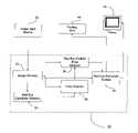
- FIG. 1illustrates a block diagram of a system for automatically detecting red-eye regions in a photographic image and for correcting red-eye regions according to an embodiment of the present invention.
- the system 100 illustrated in FIG. 1includes the following components: an image input device 20 ; an image processing unit 30 ; a printing unit 40 ; a user input unit 50 ; and a display 60 . Operation of and functional interaction between the components illustrated in FIG. 1 will become apparent from the following discussion.
- the image input device 20provides digital image data representing a color photograph.
- the image input device 20may be a scanner for scanning images recorded on film, e.g., including CCD sensors for photoelectronically reading R (red), G (green), and B (blue) image information from film, frame by frame.
- the image input device 20may be one or more of any number of devices for providing digital image data derived from photographic film or a digital camera, e.g., a recording medium (a CD-R, floppy disk, etc.) or a network connection.
- the image processing unit 30receives digital image data from the image input device 20 and performs red-eye detection and reduction in a manner discussed in detail below.
- a usermay view outputs of image processing unit 30 , including intermediate results of red-eye detection, via display 60 and may input commands to the image processing unit 30 via the user input device 50 .
- the user inputincludes a keyboard 52 and a mouse 54 .
- the image processing unit 30may perform additional image processing functions, such as known color/density correction functions, as well as image cropping, compression, etc. in accordance with commands received from the user input device 50 .
- the printing unit 40receives the output of the image processing unit 30 and generates a hard copy of the processed image data.
- the printing unit 40may expose a light-sensitive material according to image data output by the image processing unit 30 to record an image on the light-sensitive material.
- the printing unit 40may take on other forms, such as a color laser printer.
- the processed image datamay be returned to the customer as an image file, e.g., via a portable recording medium or via a network (not shown).
- FIG. 2illustrates details of the image processing unit 30 for performing red-eye detection and reduction according to a first embodiment of the present invention.
- the image processing unit 30includes: an image memory 32 , which receives digital image data from the image input device 20 ; a red-eye candidate detector 34 ; a face detector 36 ; a red-eye outline/pixel detector 38 ; and a red-eye reduction module 39 .
- an image memory 32which receives digital image data from the image input device 20 ; a red-eye candidate detector 34 ; a face detector 36 ; a red-eye outline/pixel detector 38 ; and a red-eye reduction module 39 .
- FIG. 2illustrates details of the image processing unit 30 for performing red-eye detection and reduction according to a first embodiment of the present invention.
- the image processing unit 30includes: an image memory 32 , which receives digital image data from the image input device 20 ; a red-eye candidate detector 34 ; a face detector 36 ; a red-eye outline/pixel detector 38 ; and a
- red-eye candidate detectionto find red-eye-like candidate image patches and face detection to eliminate false positives (i.e., image regions that look like possible red-eyes, but are not); and a red-eye outline/pixel detector that determines the red-eye outline and red-eye pixels within such an outline. Operation of the components of the image processing unit 30 illustrated in FIG. 2 will next be described with reference to FIGS. 3-9 .
- FIG. 3Ais a flow diagram illustrating operations performed by the red-eye candidate detector 34 in accordance with an embodiment of the present invention.
- the red-eye candidate detector 34accesses digital image data from the image memory 32 for the image being considered (S 112 ).
- the image data received by the red-eye candidate detector 34may be pre-processed, for example using local luminance equalization to enhance red-eye detection.
- local luminance equalizationmay be performed by normalizing each pixel using the average luminance for a rectangular (or some other shape) neighborhood around the pixel being normalized, for example by subtracting the average local luminance from the pixel being normalized or dividing the pixel being normalized by the average local luminance.
- known techniques for luminance adjustmentcan be applied.
- the red-eye candidate detector 34When the image data received from the image memory 32 is R, G, B data, the red-eye candidate detector 34 performs color conversion to the YCbCr color space, which captures the illuminance, blueness, and redness measurements of each pixel (S 114 ). Recognizing that the skin surrounding a red-eye often appears somewhat red or pink, an embodiment of the present application also uses an additional color channel, Cr*, that facilitates discrimination between red-eye and surrounding skin pixels. Such an auxiliary color channel is described in detail below with reference to the second embodiment of the present application.
- the input image data(e.g., 1200 ⁇ 1800 pixels) may be size adjusted (e.g., to 900 ⁇ 1350 pixels) to increase speed, more specifically so that the red-eye candidate detector 34 will not look for red-eyes that are too small.
- the red-eye candidate detector 34divides the image into overlapping image patches of fixed size (e.g., 11 ⁇ 11 pixels) and multiple scales of such a fixed size (e.g., scaled by a factor of 2, 4, 8 . . . ) (S 116 ), and calculates feature values for each image patch using the YCbCrCr* color channels. Scaling is performed since red-eyes may appear in a variety of sizes. Each calculated feature value uses pixel values from a particular color channel or a combination of color channels.
- each feature valuemay be calculated by taking an average value of a color channel over a rectangular region (e.g., an entire 11 ⁇ 11 image patch or a sub-region of the patch), or by calculating a difference of such averages in two separate rectangular areas. It should be recognized that hundreds or even thousands of different feature values are possible.
- the red-eye candidate detector 34determines whether a particular image patch represents a red-eye candidate by combining calculated feature values, thereby obtaining a classifier response (“confidence value”) (S 120 ), which is compared to a threshold value to either accept/reject the corresponding image patch as a red-eye candidate (S 122 ).
- the feature valuesmay be quantized (e.g., into 64 levels) and the threshold for accepting/rejecting red-eye candidates may be based on a histogram generated during a “learning” process (discussed in greater detail below). Having determined an initial set of red-eye candidate regions, the red-eye candidate detector 34 may perform post-processing, such as non-maximum suppression (i.e., keeping only local maximum of the classifier response) (S 124 ) and outputs the position and scale of the remaining red-eye candidates (S 126 ).
- post-processingsuch as non-maximum suppression (i.e., keeping only local maximum of the classifier response) (S 124 ) and outputs the position and scale of the remaining red-eye candidates (S 126 ).
- early rejectionmay be implemented, calculating intermediate classifier response values that are compared to intermediate thresholds, thereby allowing the system to quickly eliminate image patches as not corresponding to red-eye regions.
- This early rejection techniquemay prevent the occurrence of false negatives by using a training technique discussed below.
- Red-eyesare, essentially, small red circular blobs, but accurately and quickly identifying red-eyes presents challenges. Furthermore, if a red-eye detector is designed by hand, it is difficult to ensure that the detector is robust or applicable to many types of red-eye.
- One implementation of the present inventionchooses the alternative: learning the detector automatically from data. In particular, sufficient quantities of (positive) example images of red-eyes, and (negative) examples of non-red-eye images are gathered. The training examples may be normalized to have a fixed size (re-scaling the red-eyes as necessary). Next, machine learning methods can be applied to train the classifier to distinguish between positive and negative data. Such a classifier looks at an image patch of a fixed size (e.g., 11 ⁇ 11 pixels) and determines whether or not it represents a red-eye.
- a fixed sizee.g., 11 ⁇ 11 pixels
- Training the classifierfor a set of positive and negative examples, is an iterative process where the weak classifiers f i are learned in a sequence, and the weights of the training examples are updated so that they are higher for the examples that are more difficult, i.e., those which are misclassified by the combination of the weak classifiers learned so far.
- the red-eye detector 34should have a very low false positive rate, since each photograph will contain a huge number of potential faces or red-eyes, at different positions and scales. Thus, it is preferable to have a large set of representative negative examples. However, the same set of training examples do not have to be used at all iterations of training. Instead, bootstrapping may be applied: after every few weak classifiers, the current state of the detector is known, which is applied to background images and the patterns falsely classified as positive are extracted. These false positives become the negative training set for the next several training iterations.
- the thresholdscan be computed by analyzing a large number of positive training examples, and computing the thresholds ⁇ 1 , . .
- ⁇ Kis found by computing the intermediate classifier response f 1 ( X )+ . . . + f K ⁇ 1 ( X ) (equation 10) for each example X, setting the response to ⁇ if the example is rejected by any of the thresholds ⁇ 1 . . . ⁇ K ⁇ 1 . Then, ⁇ K is chosen so that the fraction of responses that are below ⁇ K is r K .
- the systemcan decide the order in which to apply the weak classifiers.
- the order of weak classifiersmay be learned using boosting.
- the systemcould use the greedy search method to find the first weak classifier to use (and the corresponding threshold ⁇ 1 ) so as to maximize the number of rejected negative examples; the subsequent classifiers and thresholds being found similarly.
- FIG. 3Bshows the flowchart for learning the intermediate thresholds in accordance with an implementation of the present invention.
- FIG. 3Cshows how the intermediate thresholds may be used for early rejection.
- a plurality of training examplesare input (S 150 ), corresponding to red-eye regions of various size and non-red-eye regions, and a plurality of feature values, feature 1—feature 4 in the example of FIG. 3B , are successively calculated (S 152 - 1 , S 152 - 2 , S 152 - 3 , S 152 - 4 ).
- an accumulated responseis generated for each feature value (S 154 - 1 , S 154 - 2 , S 154 - 3 , S 154 - 4 ) to calculate a plurality of intermediate thresholds (S 156 - 1 , S 156 - 2 , S 156 - 3 , S 156 - 4 ), which can subsequently be used for early rejection.
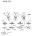
- FIG. 3Cillustrates an exemplary implementation of using such intermediate thresholds.
- image datais input (S 170 ) and a plurality of feature values, feature 1—feature 4 in the example of FIG. 3C , are successively calculated (S 172 - 1 , S 172 - 2 , S 172 - 3 , S 172 - 4 ).
- a response value for the input image datais successively calculated based on calculated feature values (S 174 - 1 , S 174 - 2 , S 174 - 3 , S 174 - 4 ), and compared to a threshold so that the input data is rejected as red-eye candidate if the accumulated response falls below the previously-calculated intermediate threshold (S 176 - 1 , S 174 - 2 , S 174 - 3 ). In this way, the steps of calculating additional feature values for a particular image region may be avoided if an intermediate response value falls below an intermediate threshold.
- FIG. 4illustrates an exemplary result of the red-eye candidate detector 34 , including a rectangle around remaining red-eye candidates.
- the red-eye candidate detectormay include false-positives, such as lights having a hue/shape that may be confused with the red-eye region.
- the face detector 36eliminates such false positives included in the set of red-eye candidates output by the red-eye candidate detector 34 .
- FIG. 5is a flow diagram illustrating operations performed by the face detector 36 in accordance with an embodiment of the present invention.
- the above-described techniques for training and early rejectionmay also be applied to face detection.
- the face detector 36eliminates false positives by eliminating red-eye candidates not associated with a face.
- the face detector 36accesses image data from the image memory 32 (S 212 ) and receives red-eye candidates (position, scale) from the red-eye candidate detector 34 (S 214 ).
- the face detector 36only utilizes luminance values, Y, to perform face detection.
- the face detector 36transforms such data into a color space that includes the luminance, Y, channel for each pixel.
- the face detector 36calculates feature values for scaled/rotated image regions containing a red-eye candidate as indicated by the red-eye candidate detector 34 (S 216 ), such calculated feature values being compared to a threshold to identify the corresponding image patch as a face region or a non-face region (S 218 ).
- the face detector 36is able to eliminate red-eye candidates not associated with a detected face region (S 220 ), and outputs the remaining red-eye candidates (S 222 ).
- images for face detectionare represented with quantized wavelet coefficients of the image luminance.
- the face detector 36may compute the Discrete Wavelet Transform (DWT) of the luminance using a 5/3 filter bank, and keep only the HL and LH bands at 3 levels of decomposition (that is, using the responses to horizontal and vertical bar filters at 3 scales).
- DWTDiscrete Wavelet Transform
- Face detection using DWT coefficientsis known and described in H. Schneiderman et al., “A statistical method for 3d object detection applied to faces and cars,” in IEEE Conf. on Computer Vision and Pattern Recognition , 2000, pp. 746-51.
- the wavelet coefficientsmay be contrast-normalized using local image variance and quantized to 7 levels each.
- Each feature used for face detectionmay be a combination of 4 quantized DWT coefficients. Therefore, each candidate face image may be represented with a set of discrete features.
- the red-eye detectionis faster (i.e., less computationally intensive) than face detection.
- the red-eyes (i)can be represented using smaller patches as compared to faces (e.g., 11 ⁇ 11 pixels for eyes vs. 31 ⁇ 28 pixels for faces), and (ii) are rotation invariant, and also more scale invariant than faces.
- facese.g., 11 ⁇ 11 pixels for eyes vs. 31 ⁇ 28 pixels for faces
- ii)are rotation invariant, and also more scale invariant than faces.
- a single orientation of the image and scales spaced by a factor of 2may be considered, whereas, for faces, 4 or 12 rotations of the image and scales spaced by a factor of 1.2 may be considered. Therefore, applying red-eye detection before face detection, and considering a candidate face only if a red-eye was detected nearby, significantly improves detection speed.
- the face detector 36may be trained, using a set of positive images containing faces and negative images without faces.
- FIG. 6illustrates an exemplary output of the face detector 36 , which, as compared to FIG. 4 , has eliminated the false positives generated by the red-eye candidate detector 34 .
- the red-eye outline/pixel detector 38accurately determines the outline for the identified red-eye regions associated with a face and pixels within the detected outline.
- FIG. 7is a flow diagram illustrating operations performed by the red-eye outline/pixel detector 38 according to an embodiment of the present invention.
- the red-eye outline/pixel detector 38initially receives red-eye positions, scale information from the face detector 36 (S 312 ), and accesses image data from image memory 32 .
- the red-eye outline/pixel detector 38calculates feature values for the identified red-eye image patches (S 314 ).
- the red-eye outline/pixel detector 38may be trained to respond to the edges of the red-eye region.
- the red-eye outline/pixel detector 38is trained in accordance with an embodiment of the present invention to respond to the top edge of the red-eye, such that the top edge of the red-eye is detected from multiple rotations of the red-eye image patch (S 316 ).
- the edge detectormay be trained in a way identical to the red-eye detector 34 , except for the geometric normalization of positive training examples. In other words, the same feature types may be used.
- the training red-eye exampleswere centered at the center of the image patch.
- Training the edge detector 38each red-eye is rotated by a random angle and the upper-most point of the rotated red-eye is placed at the center of the image patch, thus ensuring that the detector is anchored to the edge rather than the center of the red-eye.
- the red-eye outlineis detected and the red-eye pixels within the outline are output (S 318 ). It should be recognized that fewer rotations (e.g., 6, 4, or 3 rotations) or a greater number of rotations may be used.
- the red-eye outline/pixel detector 38may be used to eliminate additional false positives, e.g., based on a geometric analysis of the detected outline. For example, if the aspect ratio of the outline is not close to 1, the identified red-eye may be eliminated because red-eyes may be expected to be roughly circular in shape.
- FIG. 9illustrates an exemplary output of the red-eye outline/pixel detector 38 .
- the red-eye reduction module 39may be incorporated to change the identified pixels within the red-eye outline to a more natural color. In this process, the red-eye reduction module 39 may choose a different color for different pixels or may substitute red-eye pixels with a predetermined value.
- FIG. 10is a block diagram illustrating components of an image processing unit 30 a in accordance with a second embodiment of the present invention.
- the image processing unit 36includes the following elements: an image memory 32 a ; a red-eye candidate detector 34 a ; a face detector 36 a ; a red-eye outline/pixel detector 38 a ; a red-eye reduction module 39 a ; and a complementary red-eye pixel detector 35 .
- the red-eye candidate detector 34 a , the face detector 36 a , and the red-eye outline/pixel detector 38 amay function in like manner to the corresponding elements of the first embodiment.
- the complementary red-eye pixel detector 35further performs red-eye pixel detection, the results of which can be combined with the output of the red-eye outline/pixel detector 38 a to more accurately indicate pixels that should be subject to red-eye reduction processing by the red-eye reduction module 39 a.
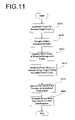
- FIG. 11is a flow diagram illustrating operations performed by the complementary red-eye pixel detector 35 in accordance with an implementation of the present invention.
- the complementary red-eye pixel detector 35effectively distinguishes red-eye pixels from surrounding pixels by converting image data into a color channel, Cr*, specifically designed to maximize differences between the red-eye pixels and surrounding pixels.
- the complementary red-eye pixel detector 35accesses image data from the image memory 32 a (S 610 ), which is subsequently processed by dividing the image into regions.
- the object of interesti.e., a red-eye
- background regionsmay span a similar range of colors.
- the second embodiment of the present applicationautomatically determines a feature to separate red-eye pixels from background pixels using training examples.
- object pixels of the input imageare known.
- a sampleis generated by normalizing its value by the background in the same image. Normalizing may be achieved by subtracting the mean value of the background from the object pixel. Alternatively, the object pixel value may be divided by the mean of the background.
- the normalized sample valuesare applied to a linear discriminant function, the Fisher linear discriminant according to an implementation of the present invention, thereby resulting a measure f that takes as input a normalized sample value and returns a value which reflects the confidence that the normalized sample value came from a red-eye.
- Sis the (mean normalized) covariance matrix of x.
- the complementary red-eye pixel detector 35normalizes each pixel value and applies f.
- the pixel xis normalized based on the mean value of a neighborhood of x, such a neighborhood being designed so as to exclude most object pixels.
- the neighborhoodis designed so that the range of colors in the neighborhood is coherent and as distinct as possible from the pixels of interest.
- the neighborhoodcan be the annulus around the red-eye area, which is expected to contain primarily skin.
- the end result of the complementary red-eye pixel detector 35is a binary mask, identifying the red-eye pixels (S 620 ).
- the output of the complementary red-eye pixel detector 35may be combined with the output of the red-eye outline/pixel detector 38 a (as shown in the embodiment of FIG. 10 ) to improve detection accuracy.
- the color channel utilized by the complementary red-eye pixel detector 35may be utilized by the red-eye candidate detector to improve detection therein and may be used as a pre-processing to reject uninteresting areas because it is fast to compute.
- FIG. 12Aillustrates an example of a red-eye condition input to the complementary red-eye pixel detector 35
- FIG. 12Billustrates an exemplary binary mask (the hatched region representing red-eye pixels) output by the complementary red-eye pixel detector 35 .
- One advantage of the complementary red-eye pixel detector 35 seen from FIG. 12Bis that interior portions of the eye that are not negatively affected by the red-eye condition are separated from the surrounding red-eye portion, such that non-affected pixels within the eye are not subject to subsequent red-eye reduction, thus preserving a natural appearance in the end result.
Landscapes
- Engineering & Computer Science (AREA)
- Theoretical Computer Science (AREA)
- Physics & Mathematics (AREA)
- General Physics & Mathematics (AREA)
- Health & Medical Sciences (AREA)
- General Health & Medical Sciences (AREA)
- Human Computer Interaction (AREA)
- Multimedia (AREA)
- Computer Vision & Pattern Recognition (AREA)
- Ophthalmology & Optometry (AREA)
- Oral & Maxillofacial Surgery (AREA)
- Image Analysis (AREA)
- Image Processing (AREA)
- Facsimile Image Signal Circuits (AREA)
Abstract
Description
f(X)=f1(X)+f2(X)+, (equation 1)
where each fk(X) is a weak classifier. Training the classifier, for a set of positive and negative examples, is an iterative process where the weak classifiers fiare learned in a sequence, and the weights of the training examples are updated so that they are higher for the examples that are more difficult, i.e., those which are misclassified by the combination of the weak classifiers learned so far.
where X1. . . XNare the training examples, and yiare the labels (1 for positive examples, −1 for negative ones). One can verify that this objective function is maximized when, for all examples, f(Xi) is high in magnitude and of the same sign as yi—but this is impossible in practice because, for the classifier to generalize, the complexity of f(X) must be constrained. To optimize the objective function, the weights of the training examples are updated after each iteration, so that, when training the (i+1)th weak classifier fi+1, a training example X=(X1, . . . ,XK) with label y=±1 receives the weight:
The image features used for red-eye and face detection (described below) can take on a finite number of values, and it is natural to consider weak classifiers that look at a single feature. For a specific feature Xk, the probabilities of observing each value xkin an object of interest P(Xk=xk|y=1): and in a random image of a background P(Xk=xk|y=−1) can be learned. Each distribution is learned from a set of weighted examples and is represented with a histogram—with a bin for each feature value x. It can be shown that, to maximize the objective function, the classifier that looks at the feature Xkmust output:
At each iteration of the training procedure, each possible feature is tried, the corresponding weak classifier is computed, the resulting value of the objective function Φ is evaluated, and the feature for which Φ is the highest is selected.
f(X)=f1(X)+f2(X)+ . . . +fN(X) (equation 5)
at each location. Many negative patterns can be rejected early, from just a few leading terms in that sum. To implement this early rejection, a set of thresholds θ1, θ2, . . . ,θNis computed, such that a pattern X is classified as positive if not only f(X)>0 but also, for each i, the ith partial sum:
f1(X)+ . . . +fi(X)≧θi. (equation 6)
These intermediate thresholds are computed by considering a large number of positive examples, selecting those that are correctly classified (i.e., those for which f(X)>0), and computing:
θi=minx(f1(X)+ . . . +fi(X)). (equation 7)
Thus, if a face example X is correctly classified, then for each i we have:
f1(X)+ . . . +fi(X)≧θi. (equation 8)
rK=R·(K/N), (equation 9)
where R is the false negative rate of the overall classifier (determined in advance). Then, the false rejection rate of the first K stages of the classifier increases linearly with K, finally reaching R when K=N. The thresholds can be computed by analyzing a large number of positive training examples, and computing the thresholds θ1, . . . ,θNone by one. θKis found by computing the intermediate classifier response
f1(X)+ . . . +fK−1(X) (equation 10)
for each example X, setting the response to −∞ if the example is rejected by any of the thresholds θ1. . . θK−1. Then, θKis chosen so that the fraction of responses that are below θKis rK.
f(x)=w*x (equation 11)
The vector w is fixed and is computed via the known Fisher method from the normalized training samples x:
w=inverse(S)+mean(x) (equation 12)
S is the (mean normalized) covariance matrix of x. Once f has been determined, the complementary red-
Claims (38)
Priority Applications (5)
| Application Number | Priority Date | Filing Date | Title |
|---|---|---|---|
| US10/440,173US7343028B2 (en) | 2003-05-19 | 2003-05-19 | Method and apparatus for red-eye detection |
| EP05027116AEP1653409B1 (en) | 2003-05-19 | 2004-05-18 | Method and apparatus for red-eye detection |
| EP04011775AEP1480168B1 (en) | 2003-05-19 | 2004-05-18 | Method and apparatus for red-eye detection |
| DE602004026504TDE602004026504D1 (en) | 2003-05-19 | 2004-05-18 | Red eye detection method and device |
| JP2004148183AJP4529172B2 (en) | 2003-05-19 | 2004-05-18 | Method and apparatus for detecting red eye region in digital image |
Applications Claiming Priority (1)
| Application Number | Priority Date | Filing Date | Title |
|---|---|---|---|
| US10/440,173US7343028B2 (en) | 2003-05-19 | 2003-05-19 | Method and apparatus for red-eye detection |
Publications (2)
| Publication Number | Publication Date |
|---|---|
| US20040233299A1 US20040233299A1 (en) | 2004-11-25 |
| US7343028B2true US7343028B2 (en) | 2008-03-11 |
Family
ID=33097935
Family Applications (1)
| Application Number | Title | Priority Date | Filing Date |
|---|---|---|---|
| US10/440,173Active2025-11-20US7343028B2 (en) | 2003-05-19 | 2003-05-19 | Method and apparatus for red-eye detection |
Country Status (4)
| Country | Link |
|---|---|
| US (1) | US7343028B2 (en) |
| EP (2) | EP1480168B1 (en) |
| JP (1) | JP4529172B2 (en) |
| DE (1) | DE602004026504D1 (en) |
Cited By (32)
| Publication number | Priority date | Publication date | Assignee | Title |
|---|---|---|---|---|
| US20050041868A1 (en)* | 2003-07-08 | 2005-02-24 | Bertrand Chupeau | Process and device for detecting faces in a colour image |
| US20050220347A1 (en)* | 2004-03-31 | 2005-10-06 | Fuji Photo Film Co., Ltd. | Particular-region detection method and apparatus, and program therefor |
| US20050232481A1 (en)* | 2004-04-16 | 2005-10-20 | Donghui Wu | Automatic red eye removal |
| US20050238217A1 (en)* | 2004-04-06 | 2005-10-27 | Fuji Photo Film Co., Ltd. | Particular-region detection method and apparatus, and program therefor |
| US20050271295A1 (en)* | 2004-05-13 | 2005-12-08 | Naohiro Tabata | Image correction apparatus |
| US20060132856A1 (en)* | 2004-11-26 | 2006-06-22 | Fuji Photo Film Co., Ltd. | Image forming method and image forming apparatus |
| US20060215880A1 (en)* | 2005-03-18 | 2006-09-28 | Rikard Berthilsson | Method for tracking objects in a scene |
| US20060257132A1 (en)* | 2005-05-16 | 2006-11-16 | Shiffer Katerina L | Methods and apparatus for automated, multi-level red eye correction |
| US20060257026A1 (en)* | 2005-05-16 | 2006-11-16 | Shiffer Katerina L | Methods and apparatus for efficient, automated red eye detection |
| US20060257017A1 (en)* | 2005-05-12 | 2006-11-16 | Huitao Luo | Classification methods, classifier determination methods, classifiers, classifier determination devices, and articles of manufacture |
| US20060274950A1 (en)* | 2005-06-06 | 2006-12-07 | Xerox Corporation | Red-eye detection and correction |
| US20070140556A1 (en)* | 2005-12-20 | 2007-06-21 | Xerox Corporation | Red eye detection and correction |
| US20070263928A1 (en)* | 2006-05-15 | 2007-11-15 | Fujifilm Corporation | Method, apparatus, and program for processing red eyes |
| US20080137944A1 (en)* | 2006-12-12 | 2008-06-12 | Luca Marchesotti | Adaptive red eye correction |
| US20090018985A1 (en)* | 2007-07-13 | 2009-01-15 | Microsoft Corporation | Histogram-based classifiers having variable bin sizes |
| US20090297048A1 (en)* | 2008-06-02 | 2009-12-03 | Massachusetts Institute Of Technology | Fast pattern classification based on a sparse transform |
| US20100303345A1 (en)* | 2009-06-01 | 2010-12-02 | Apple, Inc. | Red-eye reduction using facial detection |
| US20110081079A1 (en)* | 2009-10-07 | 2011-04-07 | Jie Wang | Automatic Red-Eye Object Classification In Digital Images Using A Boosting-Based Framework |
| US20110115949A1 (en)* | 2005-11-18 | 2011-05-19 | Tessera Technologies Ireland Limited | Two Stage Detection for Photographic Eye Artifacts |
| US20110142337A1 (en)* | 2008-08-01 | 2011-06-16 | Jonathan Deonarine | Method For Red-eye Detection |
| US20110255751A1 (en)* | 2007-07-12 | 2011-10-20 | Samsung Electronics Co., Ltd. | Digital image processing apparatus, method of controlling the same, and recording medium for storing program for executing the method |
| US20120121173A1 (en)* | 2009-05-08 | 2012-05-17 | Kazuki Aisaka | Image processing apparatus and method, and program |
| US8559707B2 (en) | 2010-12-15 | 2013-10-15 | Industrial Technology Research Institute | System and method for face detection using face region location and size predictions and computer program product thereof |
| US8571271B2 (en) | 2011-05-26 | 2013-10-29 | Microsoft Corporation | Dual-phase red eye correction |
| US8786735B2 (en) | 2011-03-21 | 2014-07-22 | Apple Inc. | Red-eye removal using multiple recognition channels |
| US8811683B2 (en) | 2011-06-02 | 2014-08-19 | Apple Inc. | Automatic red-eye repair using multiple recognition channels |
| US8818091B2 (en) | 2011-03-21 | 2014-08-26 | Apple Inc. | Red-eye removal using multiple recognition channels |
| US8837822B2 (en) | 2011-03-21 | 2014-09-16 | Apple Inc. | Red-eye removal using multiple recognition channels |
| US8837827B2 (en) | 2011-03-21 | 2014-09-16 | Apple Inc. | Red-eye removal using multiple recognition channels |
| US8837785B2 (en) | 2011-03-21 | 2014-09-16 | Apple Inc. | Red-eye removal using multiple recognition channels |
| US8970902B2 (en) | 2011-09-19 | 2015-03-03 | Hewlett-Packard Development Company, L.P. | Red-eye removal systems and method for variable data printing (VDP) workflows |
| US9041954B2 (en) | 2011-06-07 | 2015-05-26 | Hewlett-Packard Development Company, L.P. | Implementing consistent behavior across different resolutions of images |
Families Citing this family (40)
| Publication number | Priority date | Publication date | Assignee | Title |
|---|---|---|---|---|
| US7042505B1 (en) | 1997-10-09 | 2006-05-09 | Fotonation Ireland Ltd. | Red-eye filter method and apparatus |
| US7738015B2 (en) | 1997-10-09 | 2010-06-15 | Fotonation Vision Limited | Red-eye filter method and apparatus |
| US7630006B2 (en) | 1997-10-09 | 2009-12-08 | Fotonation Ireland Limited | Detecting red eye filter and apparatus using meta-data |
| US8036458B2 (en) | 2007-11-08 | 2011-10-11 | DigitalOptics Corporation Europe Limited | Detecting redeye defects in digital images |
| US7970182B2 (en) | 2005-11-18 | 2011-06-28 | Tessera Technologies Ireland Limited | Two stage detection for photographic eye artifacts |
| US8170294B2 (en) | 2006-11-10 | 2012-05-01 | DigitalOptics Corporation Europe Limited | Method of detecting redeye in a digital image |
| US8254674B2 (en) | 2004-10-28 | 2012-08-28 | DigitalOptics Corporation Europe Limited | Analyzing partial face regions for red-eye detection in acquired digital images |
| US7536036B2 (en) | 2004-10-28 | 2009-05-19 | Fotonation Vision Limited | Method and apparatus for red-eye detection in an acquired digital image |
| US7792970B2 (en) | 2005-06-17 | 2010-09-07 | Fotonation Vision Limited | Method for establishing a paired connection between media devices |
| US7587085B2 (en) | 2004-10-28 | 2009-09-08 | Fotonation Vision Limited | Method and apparatus for red-eye detection in an acquired digital image |
| US7574016B2 (en) | 2003-06-26 | 2009-08-11 | Fotonation Vision Limited | Digital image processing using face detection information |
| US7920723B2 (en) | 2005-11-18 | 2011-04-05 | Tessera Technologies Ireland Limited | Two stage detection for photographic eye artifacts |
| US8520093B2 (en) | 2003-08-05 | 2013-08-27 | DigitalOptics Corporation Europe Limited | Face tracker and partial face tracker for red-eye filter method and apparatus |
| US9412007B2 (en) | 2003-08-05 | 2016-08-09 | Fotonation Limited | Partial face detector red-eye filter method and apparatus |
| JP2005092759A (en)* | 2003-09-19 | 2005-04-07 | Fuji Photo Film Co Ltd | Image processing device and method, red-eye detection method, and program |
| JP4517633B2 (en)* | 2003-11-25 | 2010-08-04 | ソニー株式会社 | Object detection apparatus and method |
| JP4373828B2 (en)* | 2004-03-22 | 2009-11-25 | 富士フイルム株式会社 | Specific area detection method, specific area detection apparatus, and program |
| JP4757559B2 (en) | 2004-08-11 | 2011-08-24 | 富士フイルム株式会社 | Apparatus and method for detecting components of a subject |
| JP4378258B2 (en)* | 2004-10-14 | 2009-12-02 | 富士フイルム株式会社 | Image correction apparatus and control method thereof |
| JP4901229B2 (en)* | 2005-03-11 | 2012-03-21 | 富士フイルム株式会社 | Red-eye detection method, apparatus, and program |
| US7599577B2 (en) | 2005-11-18 | 2009-10-06 | Fotonation Vision Limited | Method and apparatus of correcting hybrid flash artifacts in digital images |
| EP1987475A4 (en) | 2006-02-14 | 2009-04-22 | Fotonation Vision Ltd | Automatic detection and correction of non-red eye flash defects |
| JP4549997B2 (en) | 2006-03-30 | 2010-09-22 | 富士フイルム株式会社 | Red-eye detection device, red-eye detection method, and red-eye detection program |
| EP2033142B1 (en) | 2006-06-12 | 2011-01-26 | Tessera Technologies Ireland Limited | Advances in extending the aam techniques from grayscale to color images |
| JP4895797B2 (en)* | 2006-12-26 | 2012-03-14 | アイシン精機株式会社 | Wrinkle detection device, wrinkle detection method and program |
| US20080170778A1 (en)* | 2007-01-15 | 2008-07-17 | Huitao Luo | Method and system for detection and removal of redeyes |
| US8055067B2 (en) | 2007-01-18 | 2011-11-08 | DigitalOptics Corporation Europe Limited | Color segmentation |
| JP2010520567A (en) | 2007-03-05 | 2010-06-10 | フォトネーション ビジョン リミテッド | Red-eye false detection filtering using face position and orientation |
| US8503818B2 (en) | 2007-09-25 | 2013-08-06 | DigitalOptics Corporation Europe Limited | Eye defect detection in international standards organization images |
| US8212864B2 (en) | 2008-01-30 | 2012-07-03 | DigitalOptics Corporation Europe Limited | Methods and apparatuses for using image acquisition data to detect and correct image defects |
| CN101983507A (en)* | 2008-02-01 | 2011-03-02 | 惠普开发有限公司 | Automatic redeye detection |
| US8433144B2 (en)* | 2008-03-27 | 2013-04-30 | Hewlett-Packard Development Company, L.P. | Systems and methods for detecting red-eye artifacts |
| US9053524B2 (en)* | 2008-07-30 | 2015-06-09 | Fotonation Limited | Eye beautification under inaccurate localization |
| US8081254B2 (en) | 2008-08-14 | 2011-12-20 | DigitalOptics Corporation Europe Limited | In-camera based method of detecting defect eye with high accuracy |
| US8295637B2 (en)* | 2009-01-07 | 2012-10-23 | Seiko Epson Corporation | Method of classifying red-eye objects using feature extraction and classifiers |
| JP5449460B2 (en) | 2011-06-28 | 2014-03-19 | 富士フイルム株式会社 | Image processing apparatus, image processing method, and image processing program |
| TW201328312A (en)* | 2011-12-27 | 2013-07-01 | Icatch Technology Inc | Image processing method and device for redeye correction |
| JP5867198B2 (en)* | 2012-03-14 | 2016-02-24 | オムロン株式会社 | Area designation method and area designation apparatus |
| FR2989198A1 (en)* | 2012-04-06 | 2013-10-11 | St Microelectronics Grenoble 2 | METHOD AND DEVICE FOR DETECTING AN OBJECT IN AN IMAGE |
| JP5802255B2 (en) | 2013-03-13 | 2015-10-28 | 富士フイルム株式会社 | Layout editing apparatus, layout editing method and program |
Citations (11)
| Publication number | Priority date | Publication date | Assignee | Title |
|---|---|---|---|---|
| US5432863A (en) | 1993-07-19 | 1995-07-11 | Eastman Kodak Company | Automated detection and correction of eye color defects due to flash illumination |
| US5819247A (en) | 1995-02-09 | 1998-10-06 | Lucent Technologies, Inc. | Apparatus and methods for machine learning hypotheses |
| US6252976B1 (en) | 1997-08-29 | 2001-06-26 | Eastman Kodak Company | Computer program product for redeye detection |
| US6278491B1 (en) | 1998-01-29 | 2001-08-21 | Hewlett-Packard Company | Apparatus and a method for automatically detecting and reducing red-eye in a digital image |
| US20030044177A1 (en) | 2001-09-03 | 2003-03-06 | Knut Oberhardt | Method for the automatic detection of red-eye defects in photographic image data |
| US6665434B1 (en)* | 1999-03-11 | 2003-12-16 | Fuji Photo Film Co., Ltd. | Device, method, and recordium for correcting color imbalance of an image |
| US20040170337A1 (en)* | 2003-02-28 | 2004-09-02 | Eastman Kodak Company | Method and system for enhancing portrait images that are processed in a batch mode |
| US6829384B2 (en)* | 2001-02-28 | 2004-12-07 | Carnegie Mellon University | Object finder for photographic images |
| US6980691B2 (en)* | 2001-07-05 | 2005-12-27 | Corel Corporation | Correction of “red-eye” effects in images |
| US7042505B1 (en)* | 1997-10-09 | 2006-05-09 | Fotonation Ireland Ltd. | Red-eye filter method and apparatus |
| US7082211B2 (en)* | 2002-05-31 | 2006-07-25 | Eastman Kodak Company | Method and system for enhancing portrait images |
Family Cites Families (5)
| Publication number | Priority date | Publication date | Assignee | Title |
|---|---|---|---|---|
| JP3036285B2 (en) | 1993-03-05 | 2000-04-24 | ミノルタ株式会社 | Red eye position detector |
| JP2907120B2 (en)* | 1996-05-29 | 1999-06-21 | 日本電気株式会社 | Red-eye detection correction device |
| US6009209A (en)* | 1997-06-27 | 1999-12-28 | Microsoft Corporation | Automated removal of red eye effect from a digital image |
| JP2002027242A (en)* | 2000-07-03 | 2002-01-25 | Sharp Corp | Image processing method, image processing apparatus, image forming apparatus including the same, and recording medium |
| EP1293933A1 (en)* | 2001-09-03 | 2003-03-19 | Agfa-Gevaert AG | Method for automatically detecting red-eye defects in photographic image data |
- 2003
- 2003-05-19USUS10/440,173patent/US7343028B2/enactiveActive
- 2004
- 2004-05-18DEDE602004026504Tpatent/DE602004026504D1/ennot_activeExpired - Lifetime
- 2004-05-18EPEP04011775Apatent/EP1480168B1/ennot_activeExpired - Lifetime
- 2004-05-18EPEP05027116Apatent/EP1653409B1/ennot_activeExpired - Lifetime
- 2004-05-18JPJP2004148183Apatent/JP4529172B2/ennot_activeExpired - Lifetime
Patent Citations (12)
| Publication number | Priority date | Publication date | Assignee | Title |
|---|---|---|---|---|
| US5432863A (en) | 1993-07-19 | 1995-07-11 | Eastman Kodak Company | Automated detection and correction of eye color defects due to flash illumination |
| US5819247A (en) | 1995-02-09 | 1998-10-06 | Lucent Technologies, Inc. | Apparatus and methods for machine learning hypotheses |
| US6252976B1 (en) | 1997-08-29 | 2001-06-26 | Eastman Kodak Company | Computer program product for redeye detection |
| US7042505B1 (en)* | 1997-10-09 | 2006-05-09 | Fotonation Ireland Ltd. | Red-eye filter method and apparatus |
| US6278491B1 (en) | 1998-01-29 | 2001-08-21 | Hewlett-Packard Company | Apparatus and a method for automatically detecting and reducing red-eye in a digital image |
| US6665434B1 (en)* | 1999-03-11 | 2003-12-16 | Fuji Photo Film Co., Ltd. | Device, method, and recordium for correcting color imbalance of an image |
| US6829384B2 (en)* | 2001-02-28 | 2004-12-07 | Carnegie Mellon University | Object finder for photographic images |
| US6980691B2 (en)* | 2001-07-05 | 2005-12-27 | Corel Corporation | Correction of “red-eye” effects in images |
| US20030044177A1 (en) | 2001-09-03 | 2003-03-06 | Knut Oberhardt | Method for the automatic detection of red-eye defects in photographic image data |
| US7082211B2 (en)* | 2002-05-31 | 2006-07-25 | Eastman Kodak Company | Method and system for enhancing portrait images |
| US20040170337A1 (en)* | 2003-02-28 | 2004-09-02 | Eastman Kodak Company | Method and system for enhancing portrait images that are processed in a batch mode |
| US7039222B2 (en)* | 2003-02-28 | 2006-05-02 | Eastman Kodak Company | Method and system for enhancing portrait images that are processed in a batch mode |
Non-Patent Citations (11)
| Title |
|---|
| "A Statistical Method for 3D Object Detection Applied to Faces and Cars" By Henry Schneiderman and Takeo Kanade, Robotics Institute Carnegie Mellon University, Jun. 13-15, 2000. |
| "Experiments with a New Boosting Algorithm" By Yoav Freund and Robert E. Schapire, AT&T Research, Jan. 22, 1996, pp. 1-15. |
| "Logistic Regression, AdaBoost and Bregman Distances" By Michael Collins, Robert E. Schapire, Yoram Singer, Thirteenth Annual Conference on Computational Learning Theory, 2000, pp. 1-26. |
| "Robust Real-Time Object Detection" By Paul Viola, Michael Jones, Second International Workshop on Statistical and Computational Theories of Vision-Modeling, learning, Computing, and Sampling, Vancouver, Canada, Jul. 13, 2001, pp. 1-25. |
| "The Boosting Approach to Machine Learing An Overview" By Robet E. Schapire, AT&T Labs-Research Shannon Laboratory, MSRI Workshop on Nonlinear Estimation and Classification, 2002, pp. 1-23. |
| Haro, A., et al., "Detecting and Tracking Eyes By Using Physiological Properties, Dynamics, and Appearance," Proceedings 2000 IEEE Conference on Computer Vision and Pattern Recognition, vol. 1 of 2, Jun. 13-15, 2000, pp. 163-168, XP001035597. |
| Ioffe, S., "Red Eye Detection with Machine Learning," Proceedings of 2003 IEEE Int. Conf. Image Processing, vol. 2, Sep. 14, 2003, pp. 871-874, XP010670596. |
| L. Davis et al., "Terrain Typing for Real Robots," Proceedings of the Detroit, MI Intelligent Vehicles '95 Symposium, Sep. 25-26, 1995, New York, NY, IEEE, US, Sep. 25, 1995, pp. 400-405. |
| M. Celenk, "A Color Clustering Technique for Image Segmentation," Computer Vision Graphics and Image Processing, Academic Press, Duluth, MN, vol. 52, No. 2, Nov. 1, 1990, pp. 145-170. |
| M. Ollis et al., "Vision-based perception for an automated harvester," Intelligent Robots and Systems, 1997, Proceedings of the 1997 IEEE/RSJ International Conference on Grenoble, France, Sep. 7-11, 1997, New York, NY, IEEE, US, Sep. 7, 1997, pp. 1838-1844. |
| M. Unser et al., "A Multi-Resolution Feature Reduction Technique for Image Segmentation with Multiple Components," Proceedings of the Conference on Computer Vision and Pattern Recognition, Ann Arbor, Jun. 5-9, 1988, Washington, IEEE Comp. Soc. Press, US, Jun. 5, 1988 pp. 568-573. |
Cited By (53)
| Publication number | Priority date | Publication date | Assignee | Title |
|---|---|---|---|---|
| US20050041868A1 (en)* | 2003-07-08 | 2005-02-24 | Bertrand Chupeau | Process and device for detecting faces in a colour image |
| US7551756B2 (en)* | 2003-07-08 | 2009-06-23 | Thomson Licensing | Process and device for detecting faces in a colour image |
| US20050220347A1 (en)* | 2004-03-31 | 2005-10-06 | Fuji Photo Film Co., Ltd. | Particular-region detection method and apparatus, and program therefor |
| US7613332B2 (en)* | 2004-03-31 | 2009-11-03 | Fujifilm Corporation | Particular-region detection method and apparatus, and program therefor |
| US20050238217A1 (en)* | 2004-04-06 | 2005-10-27 | Fuji Photo Film Co., Ltd. | Particular-region detection method and apparatus, and program therefor |
| US7620242B2 (en)* | 2004-04-06 | 2009-11-17 | Fujifilm Corporation | Particular-region detection method and apparatus, and program therefor |
| US20050232481A1 (en)* | 2004-04-16 | 2005-10-20 | Donghui Wu | Automatic red eye removal |
| US7852377B2 (en)* | 2004-04-16 | 2010-12-14 | Arcsoft, Inc. | Automatic red eye removal |
| US20050271295A1 (en)* | 2004-05-13 | 2005-12-08 | Naohiro Tabata | Image correction apparatus |
| US7539342B2 (en)* | 2004-05-13 | 2009-05-26 | Omron Corporation | Image correction apparatus |
| US20060132856A1 (en)* | 2004-11-26 | 2006-06-22 | Fuji Photo Film Co., Ltd. | Image forming method and image forming apparatus |
| US20060215880A1 (en)* | 2005-03-18 | 2006-09-28 | Rikard Berthilsson | Method for tracking objects in a scene |
| US8111873B2 (en)* | 2005-03-18 | 2012-02-07 | Cognimatics Ab | Method for tracking objects in a scene |
| US20060257017A1 (en)* | 2005-05-12 | 2006-11-16 | Huitao Luo | Classification methods, classifier determination methods, classifiers, classifier determination devices, and articles of manufacture |
| US7643674B2 (en)* | 2005-05-12 | 2010-01-05 | Hewlett-Packard Development Company, L.P. | Classification methods, classifier determination methods, classifiers, classifier determination devices, and articles of manufacture |
| US20060257026A1 (en)* | 2005-05-16 | 2006-11-16 | Shiffer Katerina L | Methods and apparatus for efficient, automated red eye detection |
| US20060257132A1 (en)* | 2005-05-16 | 2006-11-16 | Shiffer Katerina L | Methods and apparatus for automated, multi-level red eye correction |
| US8374403B2 (en)* | 2005-05-16 | 2013-02-12 | Cisco Technology, Inc. | Methods and apparatus for efficient, automated red eye detection |
| US7831067B2 (en)* | 2005-05-16 | 2010-11-09 | Cisco Technology, Inc. | Methods and apparatus for automated, multi-level red eye correction |
| US20060274950A1 (en)* | 2005-06-06 | 2006-12-07 | Xerox Corporation | Red-eye detection and correction |
| US7907786B2 (en) | 2005-06-06 | 2011-03-15 | Xerox Corporation | Red-eye detection and correction |
| US8160308B2 (en)* | 2005-11-18 | 2012-04-17 | DigitalOptics Corporation Europe Limited | Two stage detection for photographic eye artifacts |
| US20110115949A1 (en)* | 2005-11-18 | 2011-05-19 | Tessera Technologies Ireland Limited | Two Stage Detection for Photographic Eye Artifacts |
| US7567707B2 (en)* | 2005-12-20 | 2009-07-28 | Xerox Corporation | Red eye detection and correction |
| US20070140556A1 (en)* | 2005-12-20 | 2007-06-21 | Xerox Corporation | Red eye detection and correction |
| US20070263928A1 (en)* | 2006-05-15 | 2007-11-15 | Fujifilm Corporation | Method, apparatus, and program for processing red eyes |
| US7970180B2 (en)* | 2006-05-15 | 2011-06-28 | Fujifilm Corporation | Method, apparatus, and program for processing red eyes |
| US20080137944A1 (en)* | 2006-12-12 | 2008-06-12 | Luca Marchesotti | Adaptive red eye correction |
| US7764846B2 (en) | 2006-12-12 | 2010-07-27 | Xerox Corporation | Adaptive red eye correction |
| US20110255751A1 (en)* | 2007-07-12 | 2011-10-20 | Samsung Electronics Co., Ltd. | Digital image processing apparatus, method of controlling the same, and recording medium for storing program for executing the method |
| US7822696B2 (en)* | 2007-07-13 | 2010-10-26 | Microsoft Corporation | Histogram-based classifiers having variable bin sizes |
| US20090018985A1 (en)* | 2007-07-13 | 2009-01-15 | Microsoft Corporation | Histogram-based classifiers having variable bin sizes |
| US20090297048A1 (en)* | 2008-06-02 | 2009-12-03 | Massachusetts Institute Of Technology | Fast pattern classification based on a sparse transform |
| US8553984B2 (en)* | 2008-06-02 | 2013-10-08 | Massachusetts Institute Of Technology | Fast pattern classification based on a sparse transform |
| US8396261B2 (en)* | 2008-08-01 | 2013-03-12 | Hewlett-Packard Development Company, L.P. | Method for red-eye detection |
| US20110142337A1 (en)* | 2008-08-01 | 2011-06-16 | Jonathan Deonarine | Method For Red-eye Detection |
| US8577137B2 (en)* | 2009-05-08 | 2013-11-05 | Sony Corporation | Image processing apparatus and method, and program |
| US20120121173A1 (en)* | 2009-05-08 | 2012-05-17 | Kazuki Aisaka | Image processing apparatus and method, and program |
| US8559668B2 (en)* | 2009-06-01 | 2013-10-15 | Apple Inc. | Red-eye reduction using facial detection |
| US20100303345A1 (en)* | 2009-06-01 | 2010-12-02 | Apple, Inc. | Red-eye reduction using facial detection |
| US20110081079A1 (en)* | 2009-10-07 | 2011-04-07 | Jie Wang | Automatic Red-Eye Object Classification In Digital Images Using A Boosting-Based Framework |
| US8170332B2 (en)* | 2009-10-07 | 2012-05-01 | Seiko Epson Corporation | Automatic red-eye object classification in digital images using a boosting-based framework |
| US8559707B2 (en) | 2010-12-15 | 2013-10-15 | Industrial Technology Research Institute | System and method for face detection using face region location and size predictions and computer program product thereof |
| US8837827B2 (en) | 2011-03-21 | 2014-09-16 | Apple Inc. | Red-eye removal using multiple recognition channels |
| US8786735B2 (en) | 2011-03-21 | 2014-07-22 | Apple Inc. | Red-eye removal using multiple recognition channels |
| US8837785B2 (en) | 2011-03-21 | 2014-09-16 | Apple Inc. | Red-eye removal using multiple recognition channels |
| US8818091B2 (en) | 2011-03-21 | 2014-08-26 | Apple Inc. | Red-eye removal using multiple recognition channels |
| US8837822B2 (en) | 2011-03-21 | 2014-09-16 | Apple Inc. | Red-eye removal using multiple recognition channels |
| US8571271B2 (en) | 2011-05-26 | 2013-10-29 | Microsoft Corporation | Dual-phase red eye correction |
| US8811683B2 (en) | 2011-06-02 | 2014-08-19 | Apple Inc. | Automatic red-eye repair using multiple recognition channels |
| US9041954B2 (en) | 2011-06-07 | 2015-05-26 | Hewlett-Packard Development Company, L.P. | Implementing consistent behavior across different resolutions of images |
| US8970902B2 (en) | 2011-09-19 | 2015-03-03 | Hewlett-Packard Development Company, L.P. | Red-eye removal systems and method for variable data printing (VDP) workflows |
| US9215349B2 (en) | 2011-09-19 | 2015-12-15 | Hewlett-Packard Development Company, L.P. | Red-eye removal systems and method for variable data printing (VDP) workflows |
Also Published As
| Publication number | Publication date |
|---|---|
| JP2004348733A (en) | 2004-12-09 |
| EP1480168A3 (en) | 2005-01-19 |
| US20040233299A1 (en) | 2004-11-25 |
| DE602004026504D1 (en) | 2010-05-27 |
| EP1653409B1 (en) | 2011-07-13 |
| EP1653409A1 (en) | 2006-05-03 |
| EP1480168B1 (en) | 2010-04-14 |
| EP1480168A2 (en) | 2004-11-24 |
| JP4529172B2 (en) | 2010-08-25 |
Similar Documents
| Publication | Publication Date | Title |
|---|---|---|
| US7343028B2 (en) | Method and apparatus for red-eye detection | |
| Ioffe | Red eye detection with machine learning | |
| US6885766B2 (en) | Automatic color defect correction | |
| US8548257B2 (en) | Distinguishing between faces and non-faces | |
| US7120279B2 (en) | Method for face orientation determination in digital color images | |
| US6895112B2 (en) | Red-eye detection based on red region detection with eye confirmation | |
| US8923564B2 (en) | Face searching and detection in a digital image acquisition device | |
| EP1391842B1 (en) | Method for locating faces in digital color images | |
| US7764846B2 (en) | Adaptive red eye correction | |
| EP1223550B1 (en) | Method for detecting skin color in a digital image | |
| US8861845B2 (en) | Detecting and correcting redeye in an image | |
| US7567707B2 (en) | Red eye detection and correction | |
| JP4345622B2 (en) | Eye color estimation device | |
| US7715596B2 (en) | Method for controlling photographs of people | |
| US8605955B2 (en) | Methods and apparatuses for half-face detection | |
| US8401250B2 (en) | Detecting objects of interest in still images | |
| US8446494B2 (en) | Automatic redeye detection based on redeye and facial metric values | |
| JP2010045819A (en) | Face detecting camera and method | |
| WO2022120532A1 (en) | Presentation attack detection | |
| CN106803080B (en) | A Complementary Pedestrian Detection Method Based on Shape Boltzmann Machine | |
| Ghouzali et al. | A skin detection algorithm based on discrete cosine transform and generalized Gaussian density |
Legal Events
| Date | Code | Title | Description |
|---|---|---|---|
| AS | Assignment | Owner name:FUJI PHOTO FILM CO., LTD., JAPAN Free format text:ASSIGNMENT OF ASSIGNORS INTEREST;ASSIGNORS:IOFFE, SERGEY;CHINEN, TROY T.;REEL/FRAME:014094/0972 Effective date:20030515 | |
| AS | Assignment | Owner name:FUJIFILM HOLDINGS CORPORATION, JAPAN Free format text:CHANGE OF NAME;ASSIGNOR:FUJI PHOTO FILM CO., LTD.;REEL/FRAME:018898/0872 Effective date:20061001 Owner name:FUJIFILM HOLDINGS CORPORATION,JAPAN Free format text:CHANGE OF NAME;ASSIGNOR:FUJI PHOTO FILM CO., LTD.;REEL/FRAME:018898/0872 Effective date:20061001 | |
| AS | Assignment | Owner name:FUJIFILM CORPORATION, JAPAN Free format text:ASSIGNMENT OF ASSIGNORS INTEREST;ASSIGNOR:FUJIFILM HOLDINGS CORPORATION;REEL/FRAME:018934/0001 Effective date:20070130 Owner name:FUJIFILM CORPORATION,JAPAN Free format text:ASSIGNMENT OF ASSIGNORS INTEREST;ASSIGNOR:FUJIFILM HOLDINGS CORPORATION;REEL/FRAME:018934/0001 Effective date:20070130 | |
| FEPP | Fee payment procedure | Free format text:PAYOR NUMBER ASSIGNED (ORIGINAL EVENT CODE: ASPN); ENTITY STATUS OF PATENT OWNER: LARGE ENTITY | |
| STCF | Information on status: patent grant | Free format text:PATENTED CASE | |
| FPAY | Fee payment | Year of fee payment:4 | |
| FPAY | Fee payment | Year of fee payment:8 | |
| MAFP | Maintenance fee payment | Free format text:PAYMENT OF MAINTENANCE FEE, 12TH YEAR, LARGE ENTITY (ORIGINAL EVENT CODE: M1553); ENTITY STATUS OF PATENT OWNER: LARGE ENTITY Year of fee payment:12 |