US7342488B2 - System and method for providing home awareness - Google Patents
System and method for providing home awarenessDownload PDFInfo
- Publication number
- US7342488B2 US7342488B2US10/965,463US96546304AUS7342488B2US 7342488 B2US7342488 B2US 7342488B2US 96546304 AUS96546304 AUS 96546304AUS 7342488 B2US7342488 B2US 7342488B2
- Authority
- US
- United States
- Prior art keywords
- monitoring unit
- sensor
- text message
- household
- amenity
- Prior art date
- Legal status (The legal status is an assumption and is not a legal conclusion. Google has not performed a legal analysis and makes no representation as to the accuracy of the status listed.)
- Expired - Lifetime, expires
Links
- 238000000034methodMethods0.000titleclaimsabstractdescription25
- 238000012544monitoring processMethods0.000claimsabstractdescription88
- 230000004044responseEffects0.000claimsabstractdescription12
- XLYOFNOQVPJJNP-UHFFFAOYSA-NwaterSubstancesOXLYOFNOQVPJJNP-UHFFFAOYSA-N0.000claimsdescription13
- 239000000779smokeSubstances0.000description10
- 238000010586diagramMethods0.000description5
- 230000006399behaviorEffects0.000description4
- 230000007613environmental effectEffects0.000description4
- 238000012986modificationMethods0.000description4
- 230000004048modificationEffects0.000description4
- 238000001514detection methodMethods0.000description3
- 230000005236sound signalEffects0.000description3
- UGFAIRIUMAVXCW-UHFFFAOYSA-NCarbon monoxideChemical compound[O+]#[C-]UGFAIRIUMAVXCW-UHFFFAOYSA-N0.000description2
- XEEYBQQBJWHFJM-UHFFFAOYSA-NIronChemical compound[Fe]XEEYBQQBJWHFJM-UHFFFAOYSA-N0.000description2
- 229910002091carbon monoxideInorganic materials0.000description2
- 238000004891communicationMethods0.000description2
- 230000036541healthEffects0.000description2
- 235000013372meatNutrition0.000description2
- 239000003973paintSubstances0.000description2
- 230000008569processEffects0.000description2
- 238000012545processingMethods0.000description2
- 230000001052transient effectEffects0.000description2
- 230000005540biological transmissionEffects0.000description1
- 230000001413cellular effectEffects0.000description1
- 239000003086colorantSubstances0.000description1
- 238000001035dryingMethods0.000description1
- 238000005516engineering processMethods0.000description1
- 235000013305foodNutrition0.000description1
- 230000008014freezingEffects0.000description1
- 238000007710freezingMethods0.000description1
- 230000006870functionEffects0.000description1
- 239000011521glassSubstances0.000description1
- 238000003780insertionMethods0.000description1
- 230000037431insertionEffects0.000description1
- 238000009434installationMethods0.000description1
- 229910052742ironInorganic materials0.000description1
- 238000012423maintenanceMethods0.000description1
- 238000004519manufacturing processMethods0.000description1
- 230000003287optical effectEffects0.000description1
- 230000011664signalingEffects0.000description1
- 230000000007visual effectEffects0.000description1
- 238000005406washingMethods0.000description1
Images


Classifications
- H—ELECTRICITY
- H04—ELECTRIC COMMUNICATION TECHNIQUE
- H04N—PICTORIAL COMMUNICATION, e.g. TELEVISION
- H04N7/00—Television systems
- H04N7/18—Closed-circuit television [CCTV] systems, i.e. systems in which the video signal is not broadcast
- H04N7/181—Closed-circuit television [CCTV] systems, i.e. systems in which the video signal is not broadcast for receiving images from a plurality of remote sources
- G—PHYSICS
- G08—SIGNALLING
- G08B—SIGNALLING OR CALLING SYSTEMS; ORDER TELEGRAPHS; ALARM SYSTEMS
- G08B25/00—Alarm systems in which the location of the alarm condition is signalled to a central station, e.g. fire or police telegraphic systems
- G08B25/01—Alarm systems in which the location of the alarm condition is signalled to a central station, e.g. fire or police telegraphic systems characterised by the transmission medium
- G08B25/08—Alarm systems in which the location of the alarm condition is signalled to a central station, e.g. fire or police telegraphic systems characterised by the transmission medium using communication transmission lines
- G08B25/085—Alarm systems in which the location of the alarm condition is signalled to a central station, e.g. fire or police telegraphic systems characterised by the transmission medium using communication transmission lines using central distribution transmission lines
- G—PHYSICS
- G08—SIGNALLING
- G08B—SIGNALLING OR CALLING SYSTEMS; ORDER TELEGRAPHS; ALARM SYSTEMS
- G08B25/00—Alarm systems in which the location of the alarm condition is signalled to a central station, e.g. fire or police telegraphic systems
- G08B25/14—Central alarm receiver or annunciator arrangements
- H—ELECTRICITY
- H04—ELECTRIC COMMUNICATION TECHNIQUE
- H04N—PICTORIAL COMMUNICATION, e.g. TELEVISION
- H04N21/00—Selective content distribution, e.g. interactive television or video on demand [VOD]
- H04N21/40—Client devices specifically adapted for the reception of or interaction with content, e.g. set-top-box [STB]; Operations thereof
- H04N21/43—Processing of content or additional data, e.g. demultiplexing additional data from a digital video stream; Elementary client operations, e.g. monitoring of home network or synchronising decoder's clock; Client middleware
- H04N21/436—Interfacing a local distribution network, e.g. communicating with another STB or one or more peripheral devices inside the home
- H04N21/43615—Interfacing a Home Network, e.g. for connecting the client to a plurality of peripherals
- H—ELECTRICITY
- H04—ELECTRIC COMMUNICATION TECHNIQUE
- H04N—PICTORIAL COMMUNICATION, e.g. TELEVISION
- H04N21/00—Selective content distribution, e.g. interactive television or video on demand [VOD]
- H04N21/40—Client devices specifically adapted for the reception of or interaction with content, e.g. set-top-box [STB]; Operations thereof
- H04N21/47—End-user applications
- H04N21/488—Data services, e.g. news ticker
- H04N21/4882—Data services, e.g. news ticker for displaying messages, e.g. warnings, reminders
- H—ELECTRICITY
- H04—ELECTRIC COMMUNICATION TECHNIQUE
- H04N—PICTORIAL COMMUNICATION, e.g. TELEVISION
- H04N21/00—Selective content distribution, e.g. interactive television or video on demand [VOD]
- H04N21/40—Client devices specifically adapted for the reception of or interaction with content, e.g. set-top-box [STB]; Operations thereof
- H04N21/47—End-user applications
- H04N21/478—Supplemental services, e.g. displaying phone caller identification, shopping application
Definitions
- This inventionrelates, in general, to consumer electronic devices and, in particular, to a system and method for monitoring home status and providing home awareness to television viewers through the use of a monitoring unit in a connected home.
- Televisionprovides news and entertainment to viewers through an ever increasing offering of content made possible by local access channels, cable systems, pay-per-view channels, satellite systems, game consoles, and DVD players, for example.
- the news and entertainment options available via televisionhave increased, the amount of time viewers typically spend watching television has increased as well. Consequently, television has become the audio and visual medium of choice for providing information. Accordingly, a need has arisen for systems and methods that utilize television to provide content other than news and entertainment.
- a sensoris associated with a household amenity.
- a wireless signalis transmitted to a monitoring unit which, in turn, superimposes a text message indicative of the event onto a video signal.
- a display unitsuch as a television, is connected to the monitoring unit and displays the video signal including the superimposed text message.
- a system and method for providing environmental awarenessare disclosed.
- a plurality of sensorsmay be dispersed in the environment to transmit a wireless signal in response to an event occurrence.
- a monitoring unitresponsive to the wireless signal, superimposes a message onto a video signal which is displayed by a display unit.
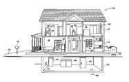
- FIG. 1is a schematic diagram of a home wherein the system for providing home awareness is being advantageously utilized
- FIG. 2is a schematic diagram of one embodiment of a system for providing home awareness
- FIG. 3is a functional block diagram of one embodiment of a system for providing home awareness
- FIG. 4is a functional block diagram of one embodiment of a wireless signal being processed by a monitoring unit of the system for providing home awareness;
- FIG. 5is a functional block diagram of another embodiment of a wireless signal being processed by a monitoring unit of the system for providing home awareness;
- FIG. 6is a flow chart of one embodiment of a method for providing home awareness.
- FIG. 7is a flow chart of one embodiment of the operation of a monitoring unit of the system for providing home awareness.
- a home 10utilizing one embodiment of a system for home awareness is depicted.
- the home 10includes a first floor 12 , a second floor 14 , a basement 16 , and a yard 18 .
- a living room 20 , an entry way 22 , and a kitchen 24are located on the first floor 12 .
- a television 26receives programming through a set top box 28 which may provide cable programming or satellite programming, for example.
- a monitoring unit 30is connected to the television 26 and the set top box 28 such that the video signal feed is relayed from the set top box 28 to the monitoring unit 30 to the television 26 .
- Sensorsare associated with various household amenities throughout the first floor 12 , second floor 14 , basement 16 , and yard 18 of the home 10 .
- Each sensoris operable to transmit a wireless signal in response to an event occurrence associated with the respective household amenity.
- the eventmay be the ringing of a doorbell, the detection of water, or the detection of a low battery, for example.
- the monitoring unit 30receives the wireless signals from the sensors and superimposes text messages indicative of the events onto the video signal that is received from the set top box 28 and transmitted to the television 26 .
- the text messagesprovide a television viewer with the ability to monitor the status of home 10 and determine home awareness while engaged in watching television programming.
- the term text messageencompasses messages comprising words, icons, symbols, and combinations thereof.
- the entry way 22includes a front door 32 having a doorbell associated therewith.
- a sensor connected to the doorbellsenses when the doorbell is rung and sends a corresponding wireless signal to the monitoring unit 30 , which superimposes the text message “DOORBELL” onto the video signal feed being provided to the television 26 .
- the television viewer or viewersread the text message and are aware of the ringing doorbell while watching the television in the living room 20 . This is particularly useful in instances where the television viewers have the television volume excessively high or the doorbell amplifier and speaker is sufficiently removed from the living room 20 .
- the kitchen 24includes a number of household amenities such as a refrigerator 34 that is equipped with a sensor that detects the status of the refrigerator door, i.e., open or closed.
- a wireless signalis transmitted from the sensor to the monitoring unit 30 .
- the monitoring unit 30superimposes the text message “REFRIGERATOR DOOR AJAR” onto the video signal feed being provided to the television 26 .
- a smoke detector 36is another household amenity that is located in the kitchen 24 .
- a sensor associated with the smoke detector 36monitors the battery and sends an appropriate wireless signal to the monitoring unit 30 when the battery becomes low. Additionally, the sensor associated with the smoke detector 36 transmits a wireless signal when the smoke detector detects smoke.
- a signal relay unit 38is located on a counter top in the kitchen 38 to relay weak wireless signals from household amenities to the monitoring unit 30 .
- the signal relay unit 38may relay weak wireless signals from the basement 16 or the lawn 18 to the monitoring unit 30 .
- the second floor 14 of the house 10includes a study 40 , a hallway 42 , and a bedroom 44 .
- a computer 46is located in the study 40 .
- a sensor associated with the computer 46sends a wireless signal to the monitoring unit 30 in response to receiving an email.
- a telephone 48is sitting on a stand in hallway 42 .
- a sensor associated with the telephone 48monitors for an incoming call and broadcasts a wireless signal in response thereto.
- the room 44includes an entry point or window 50 having a sensor associated with a security system. The sensor broadcasts a wireless signal in response to the detection of broken glass or the opening of the window 50 , for example.
- the basement 16includes a number of household amenities having sensors associated therewith that send wireless signals to the monitoring unit 30 .
- a water shut-off box 52 , a hot-water heater 54 , a washer and dryer 56 , a meat freezer 58 , and a sump pump 60each have a sensor that detects the occurrence of an event.
- the sensor associated with the water shut-off box 52may detect the condition of the water valve; namely open or closed.
- the sensor associated with the washer and dryer 56alerts the television viewer when a load has finished washing or drying.
- the sensor associated with the meat freezer 58detects an ajar door and the sensor associated with the sump pump 60 broadcasts a wireless signal upon detecting the presence of water.
- the amenities found in lawn 18may also include sensors.
- a mailbox 62may include a sensor that detects the opening and closing of the mailbox door in order to provide an indication that mail has arrived.
- a pet bowl 64may include a sensor that detects the emptying of the food in the bowl.
- the household amenities described hereinencompass simple mailboxes to complex security systems. Accordingly, it should be appreciated that the home 10 utilizing the system for providing home awareness presented herein permits members of the household to monitor any technology that the household is inclined to implement.
- the sensorsmay monitor household amenities relating to the environment, family comfort, utilities, appliances, and security.
- the sensorsmay monitor the turning ON or OFF of particular lights, power usage, the opening and closing of a garage door, the turning ON and OFF of an iron, the freezing of a pipe, the presence water leaks, the presence of gas or carbon monoxide (CO), temperature and humidity, the efficiency of an HVAC system, and the presence of smoke or fire.
- the system for home awarenessmay provide schedule reminders, medical alerts, and the like. It should be understood that although only one television is illustrated in FIG. 1 , the systems and methods presented herein may be utilized in a multiple television or multiple display environments wherein a monitoring unit associated with each display receives all or a portion of the wireless signals from the sensors and provides the appropriate text messages.
- the computer 46 located in the study 40has a monitoring unit connected therewith so that a user of the computer 46 is provided with home awareness.
- a monitoring unitconnected therewith so that a user of the computer 46 is provided with home awareness.
- FIG. 2depicts one embodiment of a system 80 for providing home awareness.
- the television 26which may be a CRT television, front projection system or flat panel system, for example, provides programming 82 by way of set top box 28 while the monitoring unit 30 receives broadcasted wireless signals from sensors associated with household amenities.
- a doorbell 84 having a sensoris positioned at the front door 32 .
- the sensor associated with the doorbellbroadcasts a wireless signal 86 that is received by the monitoring unit 30 .
- the monitoring unit 30superimposes the text message “DOORBELL” over programming 82 at the location indicated by reference numeral 88 .
- the smoke alarm 36broadcasts a wireless signal 90 upon detecting a low battery condition.
- the monitoring unit 30In response to the wireless signal 90 , the monitoring unit 30 generates the text message “SMOKE DETECTOR BATTERY LOW” and superimposes this text message onto the video signal feed that the monitoring unit 30 is relaying from the set top box 28 to the television 26 .
- the text message “SMOKE DETECTOR BATTERY LOW”is displayed at the bottom of the program 82 as indicated by reference numeral 88 .
- a viewer watching the program 82may utilize remote control 92 to affect or modify the behavior of the monitoring unit 30 .
- the remote control 92sends a wireless “snooze” signal 94 to the monitoring unit 30 , which in turn, will suppress the “SMOKE DETECTOR BATTERY LOW” message for a period of time.
- the system and method presented hereinuses a television to provide home awareness to television viewers by utilizing the reporting abilities of disparate sensors in conjunction with the communication facility of a connected home.
- FIG. 3depicts one embodiment of a system 100 for providing home awareness.
- a monitoring unit 102is coupled to a set top box 104 which provides a video signal 106 . Additionally, the set top box 104 provides an audio signal 108 . It should be appreciated that in another embodiment both the video signal 106 and the audio signal 108 may be supplied to the monitoring unit 102 .
- the monitoring unitis operable to overlay a text message onto the video signal 106 .
- a video signal 106 ′which may include the overlaid text message, and the audio signal 108 are supplied to a display unit 110 which, in one embodiment, comprises a television. It should be appreciated, however, that the display unit 110 may be a computer monitor or other device that provides for the resolution and presentation of information.
- the video signal 106is passed through the monitoring unit and is substantially identical to the video signal 106 ′.
- Sensors 112which are labeled sensor 1 through sensor n, are associated with household amenities. As illustrated, sensor 1 of the sensors 112 is transmitting a wireless signal 114 to the monitoring unit 102 .
- the sensors 112are wireless-enabled devices that provide wireless signals to the monitoring unit 102 by using any known or heretofore yet unknown wireless standard. In one embodiment, an Institute of Electrical and Electronics Engineers IEEE-based 802 standard such as 802.11 or 802.15 is utilized to transmit information from the sensors 112 to the monitoring unit 102 .
- each sensormay include a transmitter that is battery powered. In another embodiment, each sensor is embedded in the household amenity as an OEM offering.
- a control unit 116is transmitting a wireless signal 118 to the monitoring unit 102 .
- the control unitmay be utilized to program the monitoring unit 102 or alter the behavior of the monitoring unit 102 .
- the control unit 116is integrated with the monitoring unit 102 .
- the control unit 116is a television remote control, a cellular phone, Personal Digital Assistant (PDA) or other electronic device that is capable of wireless communications.
- PDAPersonal Digital Assistant
- the wireless signals 114 and 118are received by an RF receiver 120 .
- the monitoring unitis equipped with an infrared sensor.
- a processor 124communicates with the RF receiver 120 , message memory 126 , a video overlay circuit 128 , and an audio alarm 130 .
- the processor 124handles the processing of the wireless signal and, in particular, establishes the text message to be inserted by the video overlay circuit 128 based upon the content of the wireless signal and, in one embodiment, the use of the message memory 126 .
- the audio alarmmay be utilized to notify a household member of a message in instances where the television is turned OFF.
- the monitoring unit 102may turn the television ON upon receiving a wireless signal.
- each of the components of the monitoring unit 102may be any combination of hardware, software, and firmware.
- the monitoring unit 102may be integrated with the set top box 104 , the display unit 110 , or both.
- the monitoring unit 102may be integrated with a cable box, a satellite box, a video cassette device (e.g., recorder and/or player), a DVD device, a television receiver, or a monitor, for example.
- the video overlay circuit 128inserts the text message onto line 21 of the vertical blanking interval (VBI) of the video signal in a manner that is similar to closed caption signaling, which is defined by the Electronics Industry Alliance 608B (EIA-608B) standard. Further, the video overlay circuit 128 may utilize both caption channels (CC 1 and CC 2 ) and both text channels (T 1 and T 2 ) that are associated with field 1 of the EIA-608B standard. In another embodiment, the video overlay circuit 128 may utilize the additional caption channels (CC 3 and CC 4 ), additional text channels (T 1 and T 2 ), and extended data services (XDS) that are associated with field 2 of the EIA-608B standard.
- VBIvertical blanking interval
- XDSextended data services
- the video overlay circuit 128may also employ the Serial Digital Interface (SD-SDI) 601 standard or the High Definition (HD) SDI standard defined by the Advanced Television Systems Committee (ATSC).
- SD-SDI 601 standarduses line 21 of the VBI and adds the functionality that the video signal may be digital.
- HD-SDI standardallocates a data rate of 9600 bps for closed captioning use. This high data rate allows the text message to be embellished with multiple colors and a customizable caption appearance that may include characters.
- the text message or text messages superimposed by the video overlay circuit 128may be displayed in a “roll up,” “paint on,” or “pop up” mode.
- the roll up modefacilitates comprehension of the message during live events. Text messages are displayed or wiped on the television from the left to the right and then rolled up as the next line appears underneath.
- paint on modea single line of text is wiped onto the screen where it remains briefly before being wiped off.
- pop up modea complete sentence or statement is “popped” onto the television screen before being removed after a predetermined period of time.
- the monitoring unit 102may perform additional functions.
- the monitoring unit 102may be able to request the current status of a sensor or activate or de-active an actuator device that is associated with the sensor.
- both the monitoring unit 102 and a sensorare equipped with transceivers that provide for both sending and receiving signals.
- the sensorwould be equipped with the required electronics and mechanics to achieve the desired actuation.
- the monitoring unit 102is not limited to systems for providing home awareness.
- the monitoring unit 102may be utilized in applications to provide environmental awareness to individuals.
- the monitoring unit 102may be utilized in transient environments such as hotels, inns, public houses, and the like.
- the monitoring unit 102may be utilized in non residential and commercial settings such as airports, office buildings, and malls, for example.
- televisions or other types of displaysmay be positioned in heavy traffic zones, such as hallways near elevator banks or restrooms, to provide environmental awareness relative to building maintenance or, more importantly, emergency instructions detailing available exit or escape routes.
- the monitoring unitmay be connected to a television and in response to receiving a wireless signal regarding an alarm event occurrence, the monitoring unit may superimpose onto the television a text message detailing an escape route or other vital emergency instructions.
- FIG. 4depicts one embodiment of a wireless signal 140 being processed by a monitoring unit of the system for providing home awareness.
- the wireless signal 140includes a start signal portion 142 , a control signal portion 144 , a data signal portion 146 , and an end signal portion 148 .
- the start signal portion 142indicates that a valid wireless transmission is to follow. Additionally, the start signal portion 142 may include a unique identification of the sensor that provides the monitoring unit with an indication that the wireless signal to follow is authentic.
- the control signal portion 144may be a four digit number that is used to position the text on the screen. In one implementation, the first two digits may specify the row with the 01 being the top row on the screen and the maximum row value being 12. The last two digits specify the start column wherein the value 01 specifies the left side of the screen and 28 is the maximum column value. In this embodiment, a special value of 9999, for example, may be used to turn off the display and erase the text data.
- the data signal portion 146contains the text message to be superimposed onto the video signal.
- the data signal portion 146may be a variable length field that utilizes the values depicted in the following character code table (wherein the rows are indicative of the upper nibble and the columns are indicative of the lower nibble) to relay a text message.
- the end signal portion 148is utilized to terminate the wireless signal.
- control signal portion 144is accessed to determine the location in the video signal 150 to position the text message contained in the data signal portion 146 .
- FIG. 5depicts another embodiment of a wireless signal 160 being processed by a monitoring unit of the system for providing home awareness.
- the wireless signal 160includes a start signal portion 162 , a code signal portion 164 , and an end signal portion 166 .
- the start signal portion 162identifies the beginning of a valid wireless signal and the end signal portion 166 identifies the termination of the valid wireless signal.
- the code signal portion 164provides a code that is utilized to access the text message to be displayed from a database 168 .
- the code signal portion 164is employed during a table search of database 168 to access data 170 , which contains the text message and insertion instructions.
- the database 168may form a portion of the message memory 126 of FIG. 3 .
- the text messageis superimposed into the appropriate location of the video signal 172 .
- the sensorswill only have the ability to send short general text messages or numeric codes. Given the limited processing and memory capabilities of the sensors, the code signal embodiment of FIG. 5 may be preferable to the embedded data embodiment of FIG. 4 .
- FIG. 6depicts one embodiment of a method for providing home awareness.
- an occurrence of an eventis detected at a household amenity.
- a wireless signalis sent from a sensor associated with the household amenity.
- the wireless signalis received at a monitoring unit.
- a text messageis superimposed onto a video feed supplied to a television.
- the text messageis displayed on the television. It should be understood that the methodology presented in FIG. 6 is applicable to providing environmental awareness in addition to home awareness.
- FIG. 7depicts one embodiment of the operation of a monitoring unit of the system for providing home awareness.
- the monitoring unitis in an operational mode at block 200 .
- the monitoring unitreceives a wireless signal and the type of wireless signal is determined at decision block 204 . If the wireless signal is a control signal, then at block 206 the signal is interpreted and the appropriate behavior modification is implemented. Following the implementation of the behavior modification, the process returns to block 200 by way of block 208 .
- the wireless signalis an invalid signal, i.e., a signal not intended for the monitoring unit, then the signal is disregarded at block 210 and the process continues to block 208 .
- a variety of techniquesmay be utilized to determine if a wireless signal is an authentic signal from a sensor associated with a household amenity.
- a unique identification codeis assigned to each sensor during the manufacture of the sensor. During the installation of the system, each identification code is entered into the monitoring unit.
- the monitoring unitmay be configured with the use of a computer.
- the text messageis determined at block 212 .
- the text messagemay be determined using the embedded data embodiment of FIG. 4 or the code signal embodiment of FIG. 5 , for example.
- the text messageis superimposed onto the video signal.
- an audio alarmis sounded at block 218 and the methodology continues to block 208 .
- the alarmmay be sounded when the television is OFF to alert a household member that a message has been received. When the television is ON, the alarm may be sounded to emphasize a particularly important message. Otherwise, if no alarm is required, then the methodology progresses to block 208 .
Landscapes
- Engineering & Computer Science (AREA)
- Multimedia (AREA)
- Signal Processing (AREA)
- Business, Economics & Management (AREA)
- Emergency Management (AREA)
- Physics & Mathematics (AREA)
- General Physics & Mathematics (AREA)
- Alarm Systems (AREA)
- Testing, Inspecting, Measuring Of Stereoscopic Televisions And Televisions (AREA)
Abstract
Description
| TABLE I |
| Characters Displayed on the Screen |
| 0 | 1 | 2 | 3 | 4 | 5 | 6 | 7 | 8 | 9 | A | B | C | E | F | |||
| 1 | ® | ° | ½ |  | ™ |  | £ |  | à | i | è | â | ê | î | ô | û |
| 2 | = | ! | ” | # | $ | % | & | ′ | ( | ) | á | + | , | − | . | / |
| 3 | 0 | 1 | 2 | 3 | 4 | 5 | 6 | 7 | 8 | 9 | : | ; | < | 0 | > | ? |
| 4 | @ | A | B | C | D | E | F | G | H | I | J | K | L | M | N | O |
| 5 | P | Q | R | S | T | U | V | W | X | Y | Z | [ | é | ] | í | ó |
| 6 | a | b | c | d | e | f | g | h | i | j | k | l | m | n | o | |
| 7 | p | q | r | s | t | u | v | w | x | y | z | ç | ÷ | Ñ | ñ | ▮ |
| 8 | ‘ | ’ | © | SM | “ | ” | β | ¥ |  | ⊖ |  | {umlaut over ( )} | · | << | >> | |
| A | - | - | — | | | ┌ | ┐ |  | | | └ | ┘ | ⊥ | | | ├ | ┤ |  | |
| B | 0 | { | } | \ | {circumflex over ( )} | — | | | ~ | ||||||||
Claims (22)
Priority Applications (2)
| Application Number | Priority Date | Filing Date | Title |
|---|---|---|---|
| US10/965,463US7342488B2 (en) | 2004-10-13 | 2004-10-13 | System and method for providing home awareness |
| PCT/US2005/036649WO2006044443A2 (en) | 2004-10-13 | 2005-10-06 | System and method for providing home awareness |
Applications Claiming Priority (1)
| Application Number | Priority Date | Filing Date | Title |
|---|---|---|---|
| US10/965,463US7342488B2 (en) | 2004-10-13 | 2004-10-13 | System and method for providing home awareness |
Publications (2)
| Publication Number | Publication Date |
|---|---|
| US20060087428A1 US20060087428A1 (en) | 2006-04-27 |
| US7342488B2true US7342488B2 (en) | 2008-03-11 |
Family
ID=36203480
Family Applications (1)
| Application Number | Title | Priority Date | Filing Date |
|---|---|---|---|
| US10/965,463Expired - LifetimeUS7342488B2 (en) | 2004-10-13 | 2004-10-13 | System and method for providing home awareness |
Country Status (2)
| Country | Link |
|---|---|
| US (1) | US7342488B2 (en) |
| WO (1) | WO2006044443A2 (en) |
Cited By (12)
| Publication number | Priority date | Publication date | Assignee | Title |
|---|---|---|---|---|
| US20070171044A1 (en)* | 2006-01-24 | 2007-07-26 | Ollis Jeffrey D | System for reporting an adverse condition |
| US20080074277A1 (en)* | 2006-09-27 | 2008-03-27 | Mona Singh | Methods, systems, and computer program products for presenting a message on a display based on a display based on video frame types presented on the display |
| US20090249428A1 (en)* | 2008-03-31 | 2009-10-01 | At&T Knowledge Ventures, Lp | System and method of interacting with home automation systems via a set-top box device |
| US20090303033A1 (en)* | 2008-06-06 | 2009-12-10 | David Wiesenfeld | Interactive advertising display |
| US20100033319A1 (en)* | 2008-08-08 | 2010-02-11 | Pattok Greg R | Notification system and method thereof |
| US20100319021A1 (en)* | 2009-06-11 | 2010-12-16 | Embarq Holdings Company, Llc | System and method for emergency communications through a set-top box |
| US20110012746A1 (en)* | 2009-07-16 | 2011-01-20 | Fish Jr Richard T | Notification Appliance and Method Thereof |
| US20110321105A1 (en)* | 2010-06-24 | 2011-12-29 | Vanessa Ogle | System and Method for Alternate Multi-Channel Bi-Directional Data Transmission |
| US8232884B2 (en) | 2009-04-24 | 2012-07-31 | Gentex Corporation | Carbon monoxide and smoke detectors having distinct alarm indications and a test button that indicates improper operation |
| US20130049607A1 (en)* | 2010-05-21 | 2013-02-28 | Sharp Kabushiki Kaisha | Controller, method of controlling illumination, and network system |
| US10334304B2 (en) | 2013-06-12 | 2019-06-25 | Vivint, Inc. | Set top box automation |
| US10841121B1 (en) | 2019-09-30 | 2020-11-17 | Hilton International Holding Llc | Hospitality system and method of using the same |
Families Citing this family (53)
| Publication number | Priority date | Publication date | Assignee | Title |
|---|---|---|---|---|
| US7342488B2 (en) | 2004-10-13 | 2008-03-11 | Innvision Networks, Llc | System and method for providing home awareness |
| GB2436924A (en)* | 2006-04-08 | 2007-10-10 | David Everett | Portable security monitor |
| US8212681B2 (en)* | 2006-04-12 | 2012-07-03 | Gvbb Holdings S.A.R.L. | Automated theater warning technique |
| US20080085696A1 (en)* | 2006-10-10 | 2008-04-10 | Salahshour Chad S | Emergency communication system utilizing available radio frequencies and telephone lines |
| US20080211730A1 (en)* | 2007-01-26 | 2008-09-04 | Woosnam Calvin H | Gimbaled Mount System for Satellites |
| US9300993B2 (en) | 2008-08-29 | 2016-03-29 | Centurylink Intellectual Property Llc | Method and system for providing a content notification for a set-top box |
| US20100262403A1 (en)* | 2009-04-10 | 2010-10-14 | Bradford White Corporation | Systems and methods for monitoring water heaters or boilers |
| KR101563487B1 (en) | 2009-05-11 | 2015-10-27 | 엘지전자 주식회사 | Portable terminal controlling home appliance |
| US8467275B2 (en) | 2009-05-29 | 2013-06-18 | Centurylink Intellectual Property Llc | System and method for sharing user content through a set-top box |
| US8253558B2 (en)* | 2009-06-11 | 2012-08-28 | Embarq Holdings Company, Llc | System and method for emergency communication of a location through a set-top box |
| ES2337011B1 (en)* | 2009-12-07 | 2011-02-02 | Universitat Ramon Llull Fundacio Privada (20%) | DOMOTIC CONTROL PROCEDURE AND COMMUNICATIONS SYSTEM USING THIS PROCEDURE. |
| US9599981B2 (en)* | 2010-02-04 | 2017-03-21 | Echostar Uk Holdings Limited | Electronic appliance status notification via a home entertainment system |
| US8316413B2 (en) | 2010-02-04 | 2012-11-20 | Eldon Technology Limited | Apparatus for displaying electrical device usage information on a television receiver |
| US8955022B2 (en) | 2010-09-15 | 2015-02-10 | Comcast Cable Communications, Llc | Securing property |
| JP2015518950A (en) | 2012-05-10 | 2015-07-06 | ノルグレン オートメーション ソーリューションズ エルエルシーNorgren Automation Solutions,Llc. | Method and apparatus for automatically drying wet floors |
| US9955204B2 (en) | 2013-03-06 | 2018-04-24 | Centurylink Intellectual Property Llc | System and method for distributing content through a set-top box |
| US9955227B2 (en) | 2013-03-13 | 2018-04-24 | Centurylink Intellectual Property Llc | System and method for communicating alerts through a set-top box |
| US9224286B2 (en)* | 2013-03-15 | 2015-12-29 | Adt Us Holdings, Inc. | Security system health monitoring |
| KR20150056397A (en)* | 2013-11-15 | 2015-05-26 | 삼성전자주식회사 | broadcast receiving apparatus and method for displaying notice message using the same |
| US10939155B2 (en) | 2013-11-19 | 2021-03-02 | Comcast Cable Communications, Llc | Premises automation control |
| US9495860B2 (en) | 2013-12-11 | 2016-11-15 | Echostar Technologies L.L.C. | False alarm identification |
| US20150161452A1 (en) | 2013-12-11 | 2015-06-11 | Echostar Technologies, Llc | Home Monitoring and Control |
| US9900177B2 (en) | 2013-12-11 | 2018-02-20 | Echostar Technologies International Corporation | Maintaining up-to-date home automation models |
| US9769522B2 (en) | 2013-12-16 | 2017-09-19 | Echostar Technologies L.L.C. | Methods and systems for location specific operations |
| US20150181152A1 (en)* | 2013-12-20 | 2015-06-25 | Skylight Healthcare Corporation | Systems, devices and methods for interactive and bidirectional message overlay on a communications signal |
| US9767232B2 (en) | 2014-01-30 | 2017-09-19 | Schechter Tech, Llc | Temperature monitoring with simulated thermal buffer computed at a base station |
| US9723393B2 (en) | 2014-03-28 | 2017-08-01 | Echostar Technologies L.L.C. | Methods to conserve remote batteries |
| US9621959B2 (en) | 2014-08-27 | 2017-04-11 | Echostar Uk Holdings Limited | In-residence track and alert |
| US9824578B2 (en) | 2014-09-03 | 2017-11-21 | Echostar Technologies International Corporation | Home automation control using context sensitive menus |
| US9989507B2 (en) | 2014-09-25 | 2018-06-05 | Echostar Technologies International Corporation | Detection and prevention of toxic gas |
| US9511259B2 (en) | 2014-10-30 | 2016-12-06 | Echostar Uk Holdings Limited | Fitness overlay and incorporation for home automation system |
| US9983011B2 (en) | 2014-10-30 | 2018-05-29 | Echostar Technologies International Corporation | Mapping and facilitating evacuation routes in emergency situations |
| US9967614B2 (en) | 2014-12-29 | 2018-05-08 | Echostar Technologies International Corporation | Alert suspension for home automation system |
| US9729989B2 (en) | 2015-03-27 | 2017-08-08 | Echostar Technologies L.L.C. | Home automation sound detection and positioning |
| US9946857B2 (en) | 2015-05-12 | 2018-04-17 | Echostar Technologies International Corporation | Restricted access for home automation system |
| US9948477B2 (en) | 2015-05-12 | 2018-04-17 | Echostar Technologies International Corporation | Home automation weather detection |
| US9632746B2 (en) | 2015-05-18 | 2017-04-25 | Echostar Technologies L.L.C. | Automatic muting |
| US9247322B1 (en)* | 2015-05-29 | 2016-01-26 | Schechter Tech, Llc | Low-power user interface device for environmental monitoring system |
| US9960980B2 (en) | 2015-08-21 | 2018-05-01 | Echostar Technologies International Corporation | Location monitor and device cloning |
| US9996066B2 (en) | 2015-11-25 | 2018-06-12 | Echostar Technologies International Corporation | System and method for HVAC health monitoring using a television receiver |
| US10101717B2 (en) | 2015-12-15 | 2018-10-16 | Echostar Technologies International Corporation | Home automation data storage system and methods |
| US9798309B2 (en) | 2015-12-18 | 2017-10-24 | Echostar Technologies International Corporation | Home automation control based on individual profiling using audio sensor data |
| US10091017B2 (en) | 2015-12-30 | 2018-10-02 | Echostar Technologies International Corporation | Personalized home automation control based on individualized profiling |
| US10060644B2 (en) | 2015-12-31 | 2018-08-28 | Echostar Technologies International Corporation | Methods and systems for control of home automation activity based on user preferences |
| US10073428B2 (en) | 2015-12-31 | 2018-09-11 | Echostar Technologies International Corporation | Methods and systems for control of home automation activity based on user characteristics |
| US9628286B1 (en) | 2016-02-23 | 2017-04-18 | Echostar Technologies L.L.C. | Television receiver and home automation system and methods to associate data with nearby people |
| US9882736B2 (en) | 2016-06-09 | 2018-01-30 | Echostar Technologies International Corporation | Remote sound generation for a home automation system |
| CN106056864A (en)* | 2016-06-24 | 2016-10-26 | 广州市韩天然电子科技有限公司 | Household intelligent water leakage alarm system |
| US10294600B2 (en) | 2016-08-05 | 2019-05-21 | Echostar Technologies International Corporation | Remote detection of washer/dryer operation/fault condition |
| US10049515B2 (en) | 2016-08-24 | 2018-08-14 | Echostar Technologies International Corporation | Trusted user identification and management for home automation systems |
| CN106488336B (en)* | 2016-11-21 | 2019-11-12 | 株洲中车时代电气股份有限公司 | A kind of engine video frequency transmission method and system based on event corner |
| KR102397906B1 (en)* | 2017-11-02 | 2022-05-13 | 삼성전자주식회사 | Near field communication device |
| US12231257B2 (en)* | 2022-05-12 | 2025-02-18 | Ecolink Intelligent Technology, Inc. | System, method and apparatus for propagating a primary alert of a monitoring system or device |
Citations (27)
| Publication number | Priority date | Publication date | Assignee | Title |
|---|---|---|---|---|
| US4926256A (en) | 1988-08-08 | 1990-05-15 | Pioneer Electronic Corporation | Billing data display system for a closed circuit television system |
| US5543852A (en)* | 1994-06-02 | 1996-08-06 | Index Systems, Inc. | Apparatus and methods for avoiding loss of closed caption data when using extended data services |
| US5822012A (en) | 1995-08-28 | 1998-10-13 | Samsung Electronics Co., Ltd. | Home automation apparatus using a digital television receiver |
| US5867205A (en) | 1994-11-14 | 1999-02-02 | Intel Corporation | Method and apparatus for controlling video/audio and channel selection for a communication signal based on textual information indicative of channel contents of a signal |
| US20020083470A1 (en) | 2000-12-21 | 2002-06-27 | Philips Electronics North America Corporation | System and method for sending out-of-band service information to a host device |
| US6424252B1 (en)* | 2000-12-13 | 2002-07-23 | Maury Adler | Paging system for washers and dryers |
| US20020101537A1 (en) | 2001-01-31 | 2002-08-01 | International Business Machines Corporation | Universal closed caption portable receiver |
| US20030005462A1 (en)* | 2001-05-22 | 2003-01-02 | Broadus Charles R. | Noise reduction for teleconferencing within an interactive television system |
| US20030065803A1 (en) | 2001-09-28 | 2003-04-03 | Koninklijke Philips Electronics N. V. | Intelligent delivery method for streamed content |
| US20030097659A1 (en)* | 2001-11-16 | 2003-05-22 | Goldman Phillip Y. | Interrupting the output of media content in response to an event |
| US20030121036A1 (en) | 2001-12-03 | 2003-06-26 | Howard C. Lock | CATV messaging alert system |
| US20030121059A1 (en) | 2001-12-21 | 2003-06-26 | Koninklijke Philips Electronics N.V. | Method and apparatus for providing a reminder message to display |
| US6587739B1 (en)* | 2000-09-29 | 2003-07-01 | Sunbeam Products, Inc. | Appliance communication and control system and appliances for use in same |
| US20030131356A1 (en)* | 1998-12-21 | 2003-07-10 | Andrew M. Proehl | Method and apparatus for notification on a broadcast device |
| US6601103B1 (en) | 1996-08-22 | 2003-07-29 | Intel Corporation | Method and apparatus for providing personalized supplemental programming |
| US20030221198A1 (en) | 2002-05-21 | 2003-11-27 | Sloo David Hendler | Interest messaging entertainment system |
| US6732369B1 (en) | 1995-10-02 | 2004-05-04 | Starsight Telecast, Inc. | Systems and methods for contextually linking television program information |
| US20040113770A1 (en)* | 2002-07-11 | 2004-06-17 | Dietrich Falk | Monitoring system and monitoring method |
| US20040117843A1 (en)* | 2002-12-11 | 2004-06-17 | Jeyhan Karaoguz | Media exchange network supporting local and remote personalized media overlay |
| US20040148632A1 (en)* | 2003-01-23 | 2004-07-29 | Ji-Hyun Park | Remote controller and set-top-box therefor |
| US6816069B2 (en) | 1999-02-22 | 2004-11-09 | Mark P. Quigley | Command console for home monitoring system |
| US20050039219A1 (en)* | 1994-10-12 | 2005-02-17 | Pixel Instruments | Program viewing apparatus and method |
| US20050071879A1 (en)* | 2003-07-10 | 2005-03-31 | University Of Florida Research Foundation, Inc. | Smart space appliance control using a mobile communications device |
| US20050125083A1 (en)* | 2003-11-10 | 2005-06-09 | Kiko Frederick J. | Automation apparatus and methods |
| US20060012466A1 (en)* | 2004-07-13 | 2006-01-19 | Honeywell International, Inc. | Apparatus and method for wireless doorbell and security control panel interaction |
| WO2006044443A2 (en) | 2004-10-13 | 2006-04-27 | Innvision Networks, Llc | System and method for providing home awareness |
| US20060168635A1 (en)* | 2005-01-14 | 2006-07-27 | Kabushiki Kaisha Toshiba | Device control system, device control method, and control program |
Family Cites Families (4)
| Publication number | Priority date | Publication date | Assignee | Title |
|---|---|---|---|---|
| US6269364B1 (en)* | 1998-09-25 | 2001-07-31 | Intel Corporation | Method and apparatus to automatically test and modify a searchable knowledge base |
| US7133863B2 (en)* | 2000-12-28 | 2006-11-07 | Intel Corporation | Method and apparatus to search for information |
| US20040027487A1 (en)* | 2002-08-09 | 2004-02-12 | Rzadzki Robert J. | System to provide custom text and graphic information to a television system infrastructure |
| US7076484B2 (en)* | 2002-09-16 | 2006-07-11 | International Business Machines Corporation | Automated research engine |
- 2004
- 2004-10-13USUS10/965,463patent/US7342488B2/ennot_activeExpired - Lifetime
- 2005
- 2005-10-06WOPCT/US2005/036649patent/WO2006044443A2/enactiveApplication Filing
Patent Citations (28)
| Publication number | Priority date | Publication date | Assignee | Title |
|---|---|---|---|---|
| US4926256A (en) | 1988-08-08 | 1990-05-15 | Pioneer Electronic Corporation | Billing data display system for a closed circuit television system |
| US5543852A (en)* | 1994-06-02 | 1996-08-06 | Index Systems, Inc. | Apparatus and methods for avoiding loss of closed caption data when using extended data services |
| US20050039219A1 (en)* | 1994-10-12 | 2005-02-17 | Pixel Instruments | Program viewing apparatus and method |
| US5867205A (en) | 1994-11-14 | 1999-02-02 | Intel Corporation | Method and apparatus for controlling video/audio and channel selection for a communication signal based on textual information indicative of channel contents of a signal |
| US5878222A (en) | 1994-11-14 | 1999-03-02 | Intel Corporation | Method and apparatus for controlling video/audio and channel selection for a communication signal based on channel data indicative of channel contents of a signal |
| US5822012A (en) | 1995-08-28 | 1998-10-13 | Samsung Electronics Co., Ltd. | Home automation apparatus using a digital television receiver |
| US6732369B1 (en) | 1995-10-02 | 2004-05-04 | Starsight Telecast, Inc. | Systems and methods for contextually linking television program information |
| US6601103B1 (en) | 1996-08-22 | 2003-07-29 | Intel Corporation | Method and apparatus for providing personalized supplemental programming |
| US20030131356A1 (en)* | 1998-12-21 | 2003-07-10 | Andrew M. Proehl | Method and apparatus for notification on a broadcast device |
| US6816069B2 (en) | 1999-02-22 | 2004-11-09 | Mark P. Quigley | Command console for home monitoring system |
| US6587739B1 (en)* | 2000-09-29 | 2003-07-01 | Sunbeam Products, Inc. | Appliance communication and control system and appliances for use in same |
| US6424252B1 (en)* | 2000-12-13 | 2002-07-23 | Maury Adler | Paging system for washers and dryers |
| US20020083470A1 (en) | 2000-12-21 | 2002-06-27 | Philips Electronics North America Corporation | System and method for sending out-of-band service information to a host device |
| US20020101537A1 (en) | 2001-01-31 | 2002-08-01 | International Business Machines Corporation | Universal closed caption portable receiver |
| US20030005462A1 (en)* | 2001-05-22 | 2003-01-02 | Broadus Charles R. | Noise reduction for teleconferencing within an interactive television system |
| US20030065803A1 (en) | 2001-09-28 | 2003-04-03 | Koninklijke Philips Electronics N. V. | Intelligent delivery method for streamed content |
| US20030097659A1 (en)* | 2001-11-16 | 2003-05-22 | Goldman Phillip Y. | Interrupting the output of media content in response to an event |
| US20030121036A1 (en) | 2001-12-03 | 2003-06-26 | Howard C. Lock | CATV messaging alert system |
| US20030121059A1 (en) | 2001-12-21 | 2003-06-26 | Koninklijke Philips Electronics N.V. | Method and apparatus for providing a reminder message to display |
| US20030221198A1 (en) | 2002-05-21 | 2003-11-27 | Sloo David Hendler | Interest messaging entertainment system |
| US20040113770A1 (en)* | 2002-07-11 | 2004-06-17 | Dietrich Falk | Monitoring system and monitoring method |
| US20040117843A1 (en)* | 2002-12-11 | 2004-06-17 | Jeyhan Karaoguz | Media exchange network supporting local and remote personalized media overlay |
| US20040148632A1 (en)* | 2003-01-23 | 2004-07-29 | Ji-Hyun Park | Remote controller and set-top-box therefor |
| US20050071879A1 (en)* | 2003-07-10 | 2005-03-31 | University Of Florida Research Foundation, Inc. | Smart space appliance control using a mobile communications device |
| US20050125083A1 (en)* | 2003-11-10 | 2005-06-09 | Kiko Frederick J. | Automation apparatus and methods |
| US20060012466A1 (en)* | 2004-07-13 | 2006-01-19 | Honeywell International, Inc. | Apparatus and method for wireless doorbell and security control panel interaction |
| WO2006044443A2 (en) | 2004-10-13 | 2006-04-27 | Innvision Networks, Llc | System and method for providing home awareness |
| US20060168635A1 (en)* | 2005-01-14 | 2006-07-27 | Kabushiki Kaisha Toshiba | Device control system, device control method, and control program |
Cited By (23)
| Publication number | Priority date | Publication date | Assignee | Title |
|---|---|---|---|---|
| US7492253B2 (en)* | 2006-01-24 | 2009-02-17 | General Instrument Corporation | System for reporting an adverse condition |
| US20070171044A1 (en)* | 2006-01-24 | 2007-07-26 | Ollis Jeffrey D | System for reporting an adverse condition |
| US20080074277A1 (en)* | 2006-09-27 | 2008-03-27 | Mona Singh | Methods, systems, and computer program products for presenting a message on a display based on a display based on video frame types presented on the display |
| US20140240599A1 (en)* | 2006-09-27 | 2014-08-28 | Scenera Technologies, Llc | Methods, Systems, And Computer Program Products For Presenting A Message On A Display Based On A Type Of Video Image Data For Presentation On The Display |
| US7962932B2 (en)* | 2006-09-27 | 2011-06-14 | Scenera Technologies, Llc | Methods, systems, and computer program products for presenting a message on a display based on a display based on video frame types presented on the display |
| US20110210981A1 (en)* | 2006-09-27 | 2011-09-01 | Mona Singh | Methods, Systems, And Computer Program Products For Presenting A Message On A Display Based On A Type Of Video Image Data For Presentation On The Display |
| US8732744B2 (en)* | 2006-09-27 | 2014-05-20 | Scenera Technologies, Llc | Methods, systems, and computer program products for presenting a message on a display based on a type of video image data for presentation on the display |
| US8413204B2 (en)* | 2008-03-31 | 2013-04-02 | At&T Intellectual Property I, Lp | System and method of interacting with home automation systems via a set-top box device |
| US20090249428A1 (en)* | 2008-03-31 | 2009-10-01 | At&T Knowledge Ventures, Lp | System and method of interacting with home automation systems via a set-top box device |
| US9872064B2 (en) | 2008-03-31 | 2018-01-16 | At&T Intellectual Property I, L.P. | System and method of interacting with home automation systems via a set-top box device |
| US9571884B2 (en) | 2008-03-31 | 2017-02-14 | At&T Intellectual Property I, L.P. | System and method of interacting with home automation systems via a set-top box device |
| US20090303033A1 (en)* | 2008-06-06 | 2009-12-10 | David Wiesenfeld | Interactive advertising display |
| US20100033319A1 (en)* | 2008-08-08 | 2010-02-11 | Pattok Greg R | Notification system and method thereof |
| US7920053B2 (en) | 2008-08-08 | 2011-04-05 | Gentex Corporation | Notification system and method thereof |
| US8232884B2 (en) | 2009-04-24 | 2012-07-31 | Gentex Corporation | Carbon monoxide and smoke detectors having distinct alarm indications and a test button that indicates improper operation |
| US8584189B2 (en)* | 2009-06-11 | 2013-11-12 | Centurylink Intellectual Property Llc | System and method for emergency communications through a set-top box |
| US20100319021A1 (en)* | 2009-06-11 | 2010-12-16 | Embarq Holdings Company, Llc | System and method for emergency communications through a set-top box |
| US8836532B2 (en) | 2009-07-16 | 2014-09-16 | Gentex Corporation | Notification appliance and method thereof |
| US20110012746A1 (en)* | 2009-07-16 | 2011-01-20 | Fish Jr Richard T | Notification Appliance and Method Thereof |
| US20130049607A1 (en)* | 2010-05-21 | 2013-02-28 | Sharp Kabushiki Kaisha | Controller, method of controlling illumination, and network system |
| US20110321105A1 (en)* | 2010-06-24 | 2011-12-29 | Vanessa Ogle | System and Method for Alternate Multi-Channel Bi-Directional Data Transmission |
| US10334304B2 (en) | 2013-06-12 | 2019-06-25 | Vivint, Inc. | Set top box automation |
| US10841121B1 (en) | 2019-09-30 | 2020-11-17 | Hilton International Holding Llc | Hospitality system and method of using the same |
Also Published As
| Publication number | Publication date |
|---|---|
| WO2006044443A3 (en) | 2006-06-15 |
| US20060087428A1 (en) | 2006-04-27 |
| WO2006044443A2 (en) | 2006-04-27 |
Similar Documents
| Publication | Publication Date | Title |
|---|---|---|
| US7342488B2 (en) | System and method for providing home awareness | |
| US20180249188A1 (en) | Set-Top Box with Interactive Portal and System and Method for Use of Same | |
| US8019476B2 (en) | Control device, control method, recording medium, program, and building | |
| CN107741698B (en) | Linkage control method, device and system for intelligent household appliance and entrance guard equipment | |
| US8378808B1 (en) | Dual intercom-interfaced smoke/fire detection system and associated method | |
| KR20100124730A (en) | Alarm unit and alarm system | |
| US11640736B2 (en) | Controlled indoor access using smart indoor door knobs | |
| US20110260871A1 (en) | System for tracking a presence of persons in a building, a method and a computer program product | |
| US8441350B2 (en) | Apparatus and method for operation of a display device to provide a home security alarm | |
| JP2011055121A (en) | Equipment control system | |
| JP5350705B2 (en) | Controller device | |
| KR101477424B1 (en) | Smart Information Display Device Capable of Interworking with User Terminal and System Thereof | |
| JP7158274B2 (en) | Security system | |
| JP2017085582A (en) | Television information system | |
| KR101713335B1 (en) | refrigerator and silver-care system using refrigerator | |
| JP7128109B2 (en) | Security system | |
| US20200244475A1 (en) | Notification control apparatus, detection apparatus, notification control system, notification control method, and detection method | |
| JP2004146872A (en) | Housing information system | |
| JP2015225358A (en) | Home electrical equipment and absence intrusion notification system using it | |
| KR101235606B1 (en) | The wall pad | |
| JP7146623B2 (en) | Security system | |
| JP2006350505A (en) | Communication terminal, earthquake countermeasure method and program | |
| KR100734167B1 (en) | System to measure harmful gas and operate exhaust system using kitchen TV | |
| KR20150107456A (en) | Video phone, Control system using that video phone and Control method thereof | |
| JP7227761B2 (en) | Security system |
Legal Events
| Date | Code | Title | Description |
|---|---|---|---|
| AS | Assignment | Owner name:INNVISION NETWORKS, LLC, TEXAS Free format text:ASSIGNMENT OF ASSIGNORS INTEREST;ASSIGNORS:WOLFE, EDWARD H.;CHISHOLM, ERIC W.;REEL/FRAME:015898/0292 Effective date:20041012 | |
| STCF | Information on status: patent grant | Free format text:PATENTED CASE | |
| AS | Assignment | Owner name:ENSEO, INC., TEXAS Free format text:ASSIGNMENT OF ASSIGNORS INTEREST;ASSIGNOR:INNVISION NETWORKS, LLC;REEL/FRAME:025339/0214 Effective date:20101029 | |
| FPAY | Fee payment | Year of fee payment:4 | |
| FPAY | Fee payment | Year of fee payment:8 | |
| AS | Assignment | Owner name:SILICON VALLEY BANK, CALIFORNIA Free format text:SECURITY INTEREST;ASSIGNOR:ENSEO, INC.;REEL/FRAME:043210/0881 Effective date:20170712 | |
| MAFP | Maintenance fee payment | Free format text:PAYMENT OF MAINTENANCE FEE, 12TH YR, SMALL ENTITY (ORIGINAL EVENT CODE: M2553); ENTITY STATUS OF PATENT OWNER: SMALL ENTITY Year of fee payment:12 | |
| AS | Assignment | Owner name:ENSEO, LLC, TEXAS Free format text:CHANGE OF NAME;ASSIGNOR:ENSEO, INC.;REEL/FRAME:055139/0530 Effective date:20200313 | |
| AS | Assignment | Owner name:PROSPECT CAPITAL CORPORATION, NEW YORK Free format text:SECURITY INTEREST;ASSIGNORS:ENSEO, LLC;CATAPULT TECHNOLOGIES, LLC;REEL/FRAME:056462/0174 Effective date:20210602 | |
| AS | Assignment | Owner name:ENSEO, LLC, TEXAS Free format text:RELEASE BY SECURED PARTY;ASSIGNOR:SILICON VALLEY BANK;REEL/FRAME:056445/0915 Effective date:20210602 |