US7341609B2 - Reforming and hydrogen purification system - Google Patents
Reforming and hydrogen purification systemDownload PDFInfo
- Publication number
- US7341609B2 US7341609B2US10/263,949US26394902AUS7341609B2US 7341609 B2US7341609 B2US 7341609B2US 26394902 AUS26394902 AUS 26394902AUS 7341609 B2US7341609 B2US 7341609B2
- Authority
- US
- United States
- Prior art keywords
- hydrogen
- reformer
- vessel
- catalyst bed
- raffinate
- Prior art date
- Legal status (The legal status is an assumption and is not a legal conclusion. Google has not performed a legal analysis and makes no representation as to the accuracy of the status listed.)
- Expired - Lifetime, expires
Links
Images


Classifications
- C—CHEMISTRY; METALLURGY
- C01—INORGANIC CHEMISTRY
- C01B—NON-METALLIC ELEMENTS; COMPOUNDS THEREOF; METALLOIDS OR COMPOUNDS THEREOF NOT COVERED BY SUBCLASS C01C
- C01B3/00—Hydrogen; Gaseous mixtures containing hydrogen; Separation of hydrogen from mixtures containing it; Purification of hydrogen
- C01B3/50—Separation of hydrogen or hydrogen containing gases from gaseous mixtures, e.g. purification
- C01B3/501—Separation of hydrogen or hydrogen containing gases from gaseous mixtures, e.g. purification by diffusion
- C—CHEMISTRY; METALLURGY
- C01—INORGANIC CHEMISTRY
- C01B—NON-METALLIC ELEMENTS; COMPOUNDS THEREOF; METALLOIDS OR COMPOUNDS THEREOF NOT COVERED BY SUBCLASS C01C
- C01B3/00—Hydrogen; Gaseous mixtures containing hydrogen; Separation of hydrogen from mixtures containing it; Purification of hydrogen
- C01B3/02—Production of hydrogen or of gaseous mixtures containing a substantial proportion of hydrogen
- C01B3/32—Production of hydrogen or of gaseous mixtures containing a substantial proportion of hydrogen by reaction of gaseous or liquid organic compounds with gasifying agents, e.g. water, carbon dioxide, air
- C01B3/34—Production of hydrogen or of gaseous mixtures containing a substantial proportion of hydrogen by reaction of gaseous or liquid organic compounds with gasifying agents, e.g. water, carbon dioxide, air by reaction of hydrocarbons with gasifying agents
- C01B3/38—Production of hydrogen or of gaseous mixtures containing a substantial proportion of hydrogen by reaction of gaseous or liquid organic compounds with gasifying agents, e.g. water, carbon dioxide, air by reaction of hydrocarbons with gasifying agents using catalysts
- C01B3/384—Production of hydrogen or of gaseous mixtures containing a substantial proportion of hydrogen by reaction of gaseous or liquid organic compounds with gasifying agents, e.g. water, carbon dioxide, air by reaction of hydrocarbons with gasifying agents using catalysts the catalyst being continuously externally heated
- C—CHEMISTRY; METALLURGY
- C01—INORGANIC CHEMISTRY
- C01B—NON-METALLIC ELEMENTS; COMPOUNDS THEREOF; METALLOIDS OR COMPOUNDS THEREOF NOT COVERED BY SUBCLASS C01C
- C01B2203/00—Integrated processes for the production of hydrogen or synthesis gas
- C01B2203/02—Processes for making hydrogen or synthesis gas
- C01B2203/0205—Processes for making hydrogen or synthesis gas containing a reforming step
- C01B2203/0227—Processes for making hydrogen or synthesis gas containing a reforming step containing a catalytic reforming step
- C01B2203/0233—Processes for making hydrogen or synthesis gas containing a reforming step containing a catalytic reforming step the reforming step being a steam reforming step
- C—CHEMISTRY; METALLURGY
- C01—INORGANIC CHEMISTRY
- C01B—NON-METALLIC ELEMENTS; COMPOUNDS THEREOF; METALLOIDS OR COMPOUNDS THEREOF NOT COVERED BY SUBCLASS C01C
- C01B2203/00—Integrated processes for the production of hydrogen or synthesis gas
- C01B2203/04—Integrated processes for the production of hydrogen or synthesis gas containing a purification step for the hydrogen or the synthesis gas
- C01B2203/0405—Purification by membrane separation
- C01B2203/041—In-situ membrane purification during hydrogen production
- C—CHEMISTRY; METALLURGY
- C01—INORGANIC CHEMISTRY
- C01B—NON-METALLIC ELEMENTS; COMPOUNDS THEREOF; METALLOIDS OR COMPOUNDS THEREOF NOT COVERED BY SUBCLASS C01C
- C01B2203/00—Integrated processes for the production of hydrogen or synthesis gas
- C01B2203/08—Methods of heating or cooling
- C01B2203/0805—Methods of heating the process for making hydrogen or synthesis gas
- C01B2203/0811—Methods of heating the process for making hydrogen or synthesis gas by combustion of fuel
- Y—GENERAL TAGGING OF NEW TECHNOLOGICAL DEVELOPMENTS; GENERAL TAGGING OF CROSS-SECTIONAL TECHNOLOGIES SPANNING OVER SEVERAL SECTIONS OF THE IPC; TECHNICAL SUBJECTS COVERED BY FORMER USPC CROSS-REFERENCE ART COLLECTIONS [XRACs] AND DIGESTS
- Y02—TECHNOLOGIES OR APPLICATIONS FOR MITIGATION OR ADAPTATION AGAINST CLIMATE CHANGE
- Y02E—REDUCTION OF GREENHOUSE GAS [GHG] EMISSIONS, RELATED TO ENERGY GENERATION, TRANSMISSION OR DISTRIBUTION
- Y02E60/00—Enabling technologies; Technologies with a potential or indirect contribution to GHG emissions mitigation
- Y02E60/30—Hydrogen technology
- Y02E60/50—Fuel cells
- Y—GENERAL TAGGING OF NEW TECHNOLOGICAL DEVELOPMENTS; GENERAL TAGGING OF CROSS-SECTIONAL TECHNOLOGIES SPANNING OVER SEVERAL SECTIONS OF THE IPC; TECHNICAL SUBJECTS COVERED BY FORMER USPC CROSS-REFERENCE ART COLLECTIONS [XRACs] AND DIGESTS
- Y02—TECHNOLOGIES OR APPLICATIONS FOR MITIGATION OR ADAPTATION AGAINST CLIMATE CHANGE
- Y02P—CLIMATE CHANGE MITIGATION TECHNOLOGIES IN THE PRODUCTION OR PROCESSING OF GOODS
- Y02P20/00—Technologies relating to chemical industry
- Y02P20/10—Process efficiency
- Y02P20/129—Energy recovery, e.g. by cogeneration, H2recovery or pressure recovery turbines
Definitions
- the present inventionis directed to a steam reformer for producing purified hydrogen including purified hydrogen for fuel cells.
- Purified hydrogenis an important commodity in semiconductor, metallurgical, and chemical processing. It is also highly useful as a source of fuel for fuel cells, which can produce electrical power from hydrogen.
- Hydrogencan be liberated from hydrogen-containing compounds such as alcohol by reforming with steam at elevated temperatures over a catalyst bed. Since this reaction is endothermic, the heat can be supplied from an external burner, or the heat can be supplied in-situ by mixing some oxygen and partially burning some of the fuel.
- the former processis generally called steam reforming; when air or oxygen is mixed with the fuel to supply heat the process is referred to as autothermal or partial oxidation reforming.
- meanscan be employed to separate the hydrogen, e.g. via a selective membrane.
- the high purity hydrogencan then be used in an industrial process, in a fuel cell for power generation or other applications requiring purified hydrogen.
- hydrogen purificationis not used; the reformed gas is sent to a fuel cell after a selective oxidation step to further reduce carbon monoxide levels.
- the reformerwill generally require dewpoint control, careful attention to prevent high carbon monoxide levels, and integration means with the fuel cell to receive the spent gas after much of the hydrogen has been exhausted.
- the present inventionis particularly directed to a hydrogen purification reformer which may be constructed as a compact unit with efficient heating of the reformer from a burner.
- the burner gashas a minimal pressure drop in the system which results in a low power and low cost air supply for processing of the hydrogen rich fuel.
- the novel reformer system of the present inventionincludes a catalyst unit or bed which is constructed and arranged along the path of a feedstock between a feedstock input and a spaced feedstock output.
- the catalystis operable upon heating to establish an endothermic reaction on the feedstock to produce hydrogen.
- the catalystmay be of any operative material, in any available form, such as a self supporting mass, a granular mass or combination thereof. If a granular mass is used, a confining enclosure supports the mass with a construction allowing release of the hydrogen therefrom for subsequent collection via a hydrogen permeable membrane.
- a burner unithas a flue gas output stream communicating essentially directly from the burner unit to the catalyst unit and having a length substantially on the order of the length of the catalyst unit, i.e. typically the spacing between the catalyst unit's outlet and inlet.
- the flue gas streamthus passes laterally over substantially the entire length of the catalyst resulting in minimal air pressure drop in the system.
- a hydrogen collectoris located adjacent the catalyst unit to collect the purified hydrogen, or may alternatively be located downstream in the same or in a separate pressure vessel.
- the hydrogen collectormay include one or more hydrogen selective permeable membrane units located along the path of the hydrogen liberated from the catalyst bed to collect the hydrogen.
- the preferred constructionparticularly provides for the efficient functioning of the catalyst and the heating of the catalyst, the feedstock and the air supply, as well as permitting use of a relatively low pressure air supply, yielding higher energy efficiency.
- This constructionthus establishes improved heating of the catalyst to produce the free hydrogen and the extraction thereof from a catalyst unit.
- This systemfurther permits optimizing the heating pattern of the stream over the length of the bed for the internal processing of the feedstock, as hereinafter described.
- a pressure vesselcontains a closed hydrogen selective permeable membrane core unit surrounded by a catalyst bed or unit.
- a gas fired heating unithas a flue gas output which is aligned with the pressure vessel and particularly the catalyst unit.
- the heating unitcreates a flue gas stream related to the length and cross section of the catalyst unit.
- the flue gas streampasses laterally over the catalyst unit to heat the catalyst unit throughout the length thereof.
- the catalyst unitmay be heated uniformly or may be heated to a desired thermal gradient.
- the hydrogen rich feedstock passing through the heated catalyst unitis reformed, producing hydrogen.
- a substantial portion of this hydrogensubsequently passes through the hydrogen selective permeable membrane core unit, and the remaining hydrogen and other gases, hereinafter referred to as raffinate, exits the pressure vessel, passes through a pressure control device such as a back pressure regulator, and is subsequently is used to supply heat for the reforming process via the gas fired heating unit.
- the heating unitis preferably a catalytic burner which is preferably fueled by the raffinate exiting the pressure vessel.
- the burnermay be a separate burner or constructed as an integrated part of the pressure vessel. In either construction, the raffinate is mixed with air, travels through the burner, and passes a heated stream of flue gas directly from the burner over the pressure vessel.
- the pressure vesselincludes an outer shell or wall which is formed of a heat conductive material.
- a plurality of heat conductive finsare intimately affixed to the outer wall throughout the vessel, through which the heated burner flue gas passes to thoroughly heat the reforming catalyst bed contained within the pressure vessel.
- the pressure vesselis located between and defines an inlet burner flue gas passageway and an outlet burner flue gas passageway.
- the feedstockis preheated through recovery of heat from at least one of the purified hydrogen, the raffinate, and the burner flue gas, and preferably from all three sources. Even if the feedstock is fully preheated to the desired reaction temperature, the endothermic reaction within the catalyst generally requires an additional supply of heat such as from the burner flue gas in order to maintain a sufficient temperature for the desired reforming reactions to occur.
- the pressure vesselis also preferably formed with a hydrogen collection system including one or more collection structures.
- Each collection structureincludes an inner membrane core of a porous material with a metallic hydrogen permeable selective membrane affixed to the core that forms a hydrogen selective core-membrane unit.
- the metallic hydrogen selective membranemay, for example, be a palladium or a palladium-copper alloy coating, the latter which may be fabricated with plating and annealing techniques familiar to those skilled in the art.
- each core-membrane unitis separated and spaced from the catalyst unit, particularly where a granular catalyst is used, to prevent abrading contact of the thin membrane with the catalyst material.
- a guard layermay be placed between the catalyst and the membrane, where the guard is porous or contains apertures for communicating the reformed gases to the hydrogen selective permeable membrane.
- the pressure vesselis further formed in the preferred embodiment with an outer closed end and an opposite open end, which may be closed by a releasable cover or header unit.
- the input and output linesare secured to the cover.
- the linesinclude a feedstock line to input the feedstock into the catalyst bed, a raffinate output line to receive the raffinate from the catalyst unit and a purified hydrogen output line for transmitting the purified hydrogen from the core-membrane unit.
- the pressure vesselis typically formed of a metallic alloy.
- a plurality of spaced finswhich are also good conductors of heat, are firmly affixed to and extend from the pressure vessel.
- the finsmay not be necessary for heat transfer into the catalyst area, and the pressure vessel fins may then be eliminated from the preferred embodiment, with the vessel still defining the air and heating gas passageway and the exit or exhaust passageway.
- the heating systempreferably includes a controlled distribution of a stream of the burner fluid or flue gas over the catalyst unit to produce an optimal reforming of feedstock. This requires a maximum heat input at the inlet or entrance of the feedstock into the unit with a progressive patterned reduction or gradient over the length of the unit to the outlet, since a higher proportion of the endothermic reaction occurs nearest the entrance point (the inlet end) into the catalyst.
- the burner flue gases, the heated raffinate and the collected hydrogenare used to heat the cold input air to the burner and to preheat the hydrogen rich feedstock prior to passing of the feedstock through the reforming catalyst unit.
- conduitscarry the raffinate and the purified hydrogen as they exit the pressure vessel.
- the conduitseach include at least in part a metal or other heat transfer material which are coupled and preferably bonded to each other and to a corresponding third metal conduit carrying the feedstock to the catalytic unit, in counterflow fashion.
- the several conduitsare preferably coupled to each other by a high heat transfer bonding, as by welding, brazing or the like, to promote heating of the cold feedstock. Other forms of coupling the conduits may be used.
- the flue gas from a catalytic burner unit downstream of the catalyst bedis coupled to an extended length of the input feedstock line, as by locating a coiled length thereof within the outlet passageway carrying the hot exhaust flue gas.
- This constructioncan be used to preheat the feedstock with the flue gas exhaust, which is particularly advantageous when using a catalytic burner.
- a burner air inlet chamber for supplying air to the burner and an exhaust chamber for discharging of the flue gas from the catalytic unitare located in closely-spaced side-by-side orientation.
- a heat recuperatorincludes a transfer assembly extended between the two chambers to thereby capture the heat in the burner flue gas and transmit the heat to the burner inlet air, preferably in a counterflow fashion, prior to exhausting of the flue gas from the system. This construction can be used to preheat the burner inlet air with the flue gas exhaust.
- a preferred structure of the heat transfer assemblyincludes a series of relatively thin heat conductive and apertured plates which extend between and across the two chambers.
- the platesare separated by thin thermally insulating separators between the adjacent chambers to prevent the burner flue gas from passing into the air inlet chamber or passageway. These thin separators may also serve to thermally isolate the apertured plates from one another.
- the reformer apparatusis further preferably constructed by orienting of the components in a linear, parallel orientation along a linear axis.
- the maximum outputis thereby related to the proportional linear length of the related components, with the catalytic burner area, catalyst volume, and heat transfer surface areas generally remaining constant per unit length of the device.
- the location and structure of the burner, and several heat recuperating systemshave a linear orientation related to the pressure vessel.
- the capacity of the reforming systemis then directly related to the linear length of the components in the final assembly resulting in efficient and ready scaling of hydrogen generation.
- Various monitorsmay be and preferably are coupled to the fluids within the system to control the operation of the reformer.
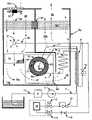
- FIG. 1is a schematic illustration of a steam reformer unit for producing purified hydrogen coupled to a fuel cell
- FIG. 2is a pictorial view of a hydrogen purifying unit
- FIG. 2 ais a view of the hydrogen purifying unit of FIG. 2 with a partial removal of the outer walls;
- FIG. 3is a rear perspective view of FIG. 2 a;
- FIG. 4is a rear perspective view of a hydrogen reformer unit shown in FIG. 2 with a reformer vessel unit removed;
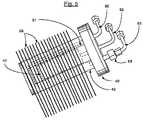
- FIG. 5is a perspective view the vessel unit shown in FIG. 4 for reforming of purified hydrogen
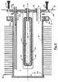
- FIG. 6is an exploded cross sectional view of the vessel unit shown in FIG. 5 .
- FIG. 7is a cross section of the vessel unit shown in FIGS. 5 and 6 ;
- FIG. 7 ais an enlarged fragmentary sectional view of parts shown in FIGS. 6 and 7 to illustrate a detail of a sealing unit
- FIG. 8is a right front perspective view of the hydrogen reformer unit shown in FIG. 4 with the outer enclosure partially removed;
- FIG. 8 ais a sectional view of a brazed connection of system fluid lines to preheat the feedstock fuel prior to introduction into the pressure vessel;
- FIG. 9is a left front perspective view of the reformer unit shown in FIGS. 4 and 8 , with the outer enclosure partially removed;
- FIG. 9 ais a left rear perspective view of the reformer unit shown in FIG. 9 ;
- FIG. 9 bis a cross-sectional view illustrating a parallel heat processing input passageway and an exhaust output passageway with the inter-related system components
- FIG. 10is an end view of a heat transfer and recuperative unit shown in FIGS. 8 and 9 - 9 b for preheating the air supply to the burner in the instance where the seal between the plates is only formed in one axis;
- FIG. 11is an enlarged view of a heat transfer plate of FIG. 10 with an improved plate separating structure
- FIG. 12is a graphical illustration of the heat input to the catalytic bed and the resulting free hydrogen created.
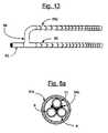
- FIG. 13is a view of a structure for supplying raffinate to the burner to provide a dispersed flue gas to the finned pressure vessel.
- FIG. 1is a simplified illustration of a system for generating purified hydrogen from a hydrogen rich fuel source 1 for consumption by device 14 , which may, for example, be a fuel cell used for supplying electrical power to a load.
- the illustrated embodiment of FIG. 1includes a unique hydrogen purifier 18 within a suitable support such as outer housing 36 , in combination with the associated components.
- the system of FIG. 1includes a steam reformer having a reformer pressure vessel unit 19 which is operable to process fuel/water feedstock from a source 1 .
- a common pump for the fuel and wateris illustrated for the case where the fuel and water are miscible as a pre-mixed feedstock, it is understood that more than one pump may be used for the fuel and water, respectively, along with any needed flow and pressure monitoring means, with the fuel and water streams meeting together prior to arriving at the catalyst filled chamber 7 .
- the pressure vessel unit 19contains an inner hydrogen purifier core unit 18 .
- the pressure vessel unit 19is larger than the unit 18 and forms the catalyst-filled chamber 7 .
- the fuel from source 1is shown as a mixture of fuel and water and constitutes a feedstock which is pulled through line 17 to filter 2 , and pumped by a pump 3 via a line 4 to the counterflow heat exchanger 9 . After receiving heat at heat exchanger 9 the feedstock then receives more heat in heat exchanger 5 , finally arriving at pressure vessel 19 by means of line 6 into pressure vessel inlet connection 60 . The feedstock thus is fed into catalyst filled chamber 7 , which is heated, as hereinafter described, and the fuel/water feedstock reacts to produce free hydrogen.
- Unit 18is an elongate member which contains a special hydrogen selective permeable membrane, as hereinafter described, which passes the hydrogen contained in the reformed gases into the interior of unit 18 , wherein the purified hydrogen is subsequently transferred to line 11 by means of hydrogen outlet 62 . While generally illustrated as a tubular member the shape of unit 18 is not constricted to any particular form, and can assume any form suitable for the application. Hydrogen purified by unit 18 and passing through line 11 transmits heat to the feedstock in heat exchanger 9 prior to passing through hydrogen output pressure regulator 12 . Once the hydrogen pressure has been regulated by regulator 12 the hydrogen may then pass through solenoid valve 13 to consuming device 14 . Since consuming device 14 may consist of a fuel cell with a required periodic bleed, a return line from consuming device 14 is included, with passage through bleed solenoid valve 15 and check valve 16 , where the bleed hydrogen is injected into line 83 .
- consuming device 14may consist of a fuel cell with a required periodic bleed, a return line from
- the volume and activity of catalyst 7 and the heating thereofis such that the processed fuel is nearly completely steam-reformed by the time it is withdrawn through line 8 .
- raffinateThe remaining fuel and reaction by-products, including unliberated hydrogen, hereinafter referred to as raffinate, is withdrawn from catalyst-filled chamber 7 by a line 8 .
- the raffinatethen transmits heat to the incoming feedstock in heat exchanger 9 , after which it passes through feedstock back pressure regulator 10 .
- the raffinatedepressurizes upon passing through regulator 10 and travels though line 83 to burner distributor 21 .
- a catalytic burner 75is mounted within outer housing 36 to receive raffinate from distributor 21 mixed with burner air.
- the raffinateis discharged into the air flow via pores or holes in distributor 21 , such as more clearly shown in FIG. 13 for a dual-distributor mechanism.
- the air and raffinateare mixed at the input to burner 75 which creates a hot flue gas stream 75 a which passes into the adjacent chamber and functions as described above to heat the catalyst filled chamber 7 .
- the system shown in FIG. 1provides particular features for improving the efficiency and functioning of the reforming process for the generation and purification of hydrogen.
- the systemprovides various heat recovery from the heated fluids in the lines at heat exchanger 9 and the heated flue gases 78 a which flow downstream of heat exchanger 5 .
- the portions of lines 4 , 8 and 11are coupled to each other by a counterflow heat exchange unit 9 which transfers heat from the reformed gases back to the incoming feedstock in counterflow fashion. This improves efficiency and also serves to cool the gas prior to arrival at hydrogen output regulator 12 and feedstock pressure regulator 10 , protecting the devices from thermal damage.
- the line 4is shown with a coiled heat exchanger section 5 which is in contact with the burner flue gas 79 .
- Heat exchanger 5is configured to raise the feedstock to the desired operating temperature for the catalyst in catalyst-filled chamber 7 .
- heat exchanger 5may include several turns of finned tubing to facilitate heat transfer from flue gas 79 , or it may consist of an unfinned tube with one or more parallel turns.
- a heat transfer assembly 30is located spanning the exhaust chamber 91 and the burner air inlet chamber 90 downstream of fan 20 and fan filter 20 a .
- a backup fan 20 bas illustrated in FIG. 2 a , may also be used in series with the main fan 20 .
- the hot flue gas 78 a entering assembly 30raises the temperature of the assembly 30 on the flue gas side which transmits the heat into the cool portion of the assembly 30 on the air inlet in a counterflow fashion.
- the assembly 30is specially constructed to prevent the transfer of fluids in the respective chambers into the other chamber, as more fully described in a preferred construction of the system of FIG. 1 , as shown in FIGS. 2-12 , by the use of thermally insulating sealing gasket 97 . Insulating gaskets 97 furthermore allow the perforated or expanded metal plates 96 of assembly 30 to operate at different temperatures such that counterflow exchange may be improved.
- FIG. 1While the arrangement of heat exchangers regulators, valves, and the like illustrated in FIG. 1 are specifically shown in a preferred orientation, various arrangements of parts may be employed to achieve similar results within the framework of the invention, and may be arranged as needed by those skilled in the art.
- a compact hydrogen source unit 33includes an outer enclosure wall 34 (partially shown in FIGS. 2 a - 4 ) within which an air supply section 35 is formed across the front wall, and connected to a hydrogen generating unit enclosed in enclosure 36 .
- a control section 37is located to the one side of the air supply section 35 and the hydrogen generator unit in enclosure 36 .
- Section 37contains various parts previously described in FIG. 1 such as the pressure regulation and solenoid valves.
- the air supply section 35includes a housing with an air filter 20 a within which an air supply fan 20 is located with a backup fan 20 b downstream of fan 20 .
- the backup fan 20 bis an axial type, and the main fan 20 is of a blower type.
- Fan 20pulls air through filter 20 a and blows it into a housing surrounding backup fan 20 b .
- An air passageway tube 38connects the output end of backup fan 20 b to the hydrogen generator unit in enclosure 36 .
- the outer face of the housing 35 ais covered by filter 20 a and an outer apertured face cover 38 b.
- the hydrogen generator unit in enclosure 36is mounted behind the air supply section 35 and is surrounded by perimeter insulation 39 resting on a rigid thermally insulating base support platform 39 a .
- the insulation surrounding the high temperature parts contained in enclosure 36permits the efficient operation of the reformer. Specifically this is done by placing the metallic fastening means to enclosure 36 at the lowest temperature portion of enclosure 36 . This includes the air passageway tube 38 , and the top of unit 33 in FIG. 2 , to which enclosure 36 is fastened. This permits structural attachment of enclosure 36 to the rest of device 33 while minimizing thermal losses.
- the input of the air to the generating unit in enclosure 36is via the air passageway tube 38 .
- the perimeter wall insulation 39is only partially shown for clarity of illustrations and understanding of the processing of the air and heating fuel system of the preferred system.
- the pressure vessel 40includes an outer shell or container 42 within which an inner purifier core unit 41 which is centrally located and secured.
- a separate cup-shape guard member 51is secured between the outer shell or container 42 and the purifier core unit 41 .
- the guard member 51is spaced from the container 42 and forms a catalyst chamber 7 and is also spaced from the core unit 41 to prevent abutting engagement of a granular catalyst 50 in chamber 7 with the core unit 41 .
- the container 42includes an outer tubular wall 45 , open at both ends prior to assembly.
- the outer endis closed by a flat end wall 46 welded with weld 47 a ( 47 a denoting all welds in FIGS. 6 and 7 ) to the tube 45 and spaced from the inner ends of the cup-shaped guard member 51 and purifier core unit 41 .
- the opposite or inner end of the tube 45is closed by a header unit 46 a including a flange member 47 secured to the open end of the tube 45 , as by a weldment 47 a .
- Header unit 46 ais bolted with bolts 53 in a sealed connection using copper seal ring 52 a to the flange member 47 .
- the guard member 51 and the purifier core unit 41are secured to the header 46 a to form a removable unit relative to the flange 47 and the outer shell 45 or container 42 .
- Cover 64is also attached to the flange 46 a via bolts 53 .
- the cup-shaped guard member 51is formed of suitable perforated metal or other suitable material to confine the catalyst 50 and to permit free passage of the hydrogen as well as other gaseous material.
- the open end of the guard member 51is secured to the header 46 a by welding or other connecting means.
- the purifier core unit 41is formed of a porous ceramic body 41 a with an outer hydrogen permeable metal coating 41 b , with presently known materials such as palladium or a palladium copper alloy coating, forming a hydrogen selective membrane, and thus a hydrogen purifier core unit 41 .
- the reformed gasespass freely through the guard 51 into the core unit 41 .
- the hydrogen gasonly passes into the inner collection chamber 41 c of the core unit 41 as a result of traversing the outer hydrogen selective membrane 41 b .
- the guard 51may take the form of a porous wall, an apertured wall or even a tubular member directing the free hydrogen toward the end thereof, with the hydrogen discharging therefrom, into the membrane unit. Where the catalyst is in the form of one or more monolithic catalyst elements or units mounted in spaced relation to the selective membrane unit or units, the guard 51 may not be necessary.
- the flange 47is recessed and telescoped over the outer end of the tube 45 and is welded to the exterior of the tube 45 as at 47 a .
- the header 46 ais bolted to the flange 47 with a high pressure sealed gasket 52 a therebetween.
- the illustrated sealed joint( FIG. 7 a ) includes a copper seal ring 52 a located between the flange 47 and header 46 a .
- a sharp sealing edge 52 cprojects outwardly from 47 and 46 a into embedded engagement with the copper ring 52 a upon tightening of the securement bolts 53 .
- the sealestablishes a high pressure closure to confine reformed gases within vessel 40 .
- Other suitable sealsmay be used in the preferred system, and in other systems may be constructed without a removable cover structure.
- end piece 46 amay be welded or brazed to the end of tube 45 for a permanent closure of pressure vessel 40 .
- the input/output linesare sealed within header 46 a and are coupled to the several passages within the core unit 41 and catalyst chamber 7 of the illustrated embodiment, as follows.
- a feedstock fuel line 60is secured in sealed relation to the header 46 a .
- the fuel line 60extends inwardly into the catalyst-filled chamber 7 , and through the catalyst 50 to the inner end portion of the chamber.
- the inner end of line 60terminates, close to the end wall 46 to feed the hydrogen rich feedstock fuel into the closed end of the catalyst filled chamber 7 , under appropriate pressure, to move the feedstock axially through the catalyst 50 toward the header 46 a .
- An alternate arrangement within the scope of this inventionutilizes a feedstock delivery tube 60 and a raffinate exit tube 63 which extends the length of catalyst bed 7 , where the tubes are closed at the ends and perforated, such that the gas flows between the perforated tubes rather than down the axial length of the catalyst bed.
- Other arrangements within the pressure vessel apparent to those skilled within the artcan be implemented as well.
- a hydrogen recovery line 62is secured within the header 46 a and terminates at the inner core chamber 41 c of core unit 41 and serves to recover the free hydrogen which has passed through the membrane 41 b of purifier core unit 41 .
- a raffinate line 63is secured to the header 46 a in alignment with the lower or bottom side of the catalyst chamber 7 .
- the pressurized feedstockpasses through the catalyst 50 and exits as raffinate through the raffinate line 63 under pressure.
- the raffinategenerally contains a significant level of hydrogen and functions as a fuel for the catalytic burner in the air passageway, as hereinafter described.
- the raffinate at the outlet of the catalyst, downstream of the purifier unit 41can provide a fuel to a catalytic or other burner unit. Unreformed fuel, unrecovered hydrogen, and side-reaction products such as carbon monoxide or methane can serve to function as a fuel in a catalytic or other burners.
- the particulars of gases contained in the raffinatedepend upon the fuel type, steam-to-carbon ratio, pressure, catalyst type, flow rate, and temperature, and may also vary depending on the time on stream of the catalyst.
- raffinateThe reformed feedstock with hydrogen removed by purifier 41 is generically identified herein as raffinate, which will cover all reformed feedstock exiting a catalyst unit and a hydrogen purification unit and coupled to the system burner, as disclosed herein, as well as such fuel when combined with or replaced by a separate fuel source.
- the container 42 and particularly the tubular wall 45has spaced and heat conductive fins 59 intimately secured, as by brazing or other high heat transmitting connection, to the container wall 45 .
- the fins 59are shown as rectangular members which are shaped and formed to fit within the corresponding opening in the enclosure for optimal heating of the catalyst and generation of purified hydrogen, as hereinafter described.
- the fins 59are spaced, with size and positioning selected to provide rapid heating of the vessel, while yielding a minimal pressure drop for the laterally passing flue gas flow.
- the fins 59are preferably formed of a suitable material such as copper for rapid heat transfer to the vessel, and particularly to catalyst 50 .
- the pressure vessel 40( FIG. 4 ) is removably secured within an opening 65 in the enclosure 36 by a plate 64 secured to the header 46 a and to the enclosure frame structure by attachment screws 65 a .
- the finned vessel 40is enclosed within an internal wall structure to define an air/fuel inlet passageway and an outer exhaust passageway, as hereinafter described.
- the finned pressure vessel 40 and particularly purifier core unit 41 thereofmay require replacement in the event that a breach or other degradation of membrane 41 b occurs, or if the catalyst activity declines significantly due to coking, poisoning, aging, or other reasons.
- the other componentsare expected to have a long life.
- the finned pressure vessel 40is removable as a unit.
- the illustrated header 46 amay be released from flange 47 and replaced by a new header with a new core unit and guard unit within the finned container 42 .
- the catalystmay also be replaced during this operation, which is particularly straightforward if the catalyst is formed as a monolithic annular piece rather than the granular material illustrated as 50 .
- the illustrated unitthus provides for a low cost replacement purifier 41 and pressure vessel 40 for simple serviceability and long life operation of the reformer.
- the feedstock feed line 60 , the hydrogen (H 2 ) recovery line 62 and the raffinate line 63are secured to header 46 a in spaced relation for inputting the feedstock and withdrawing the purified hydrogen and the raffinate, relative to container 42 , as shown in FIGS. 8 and 9 .
- Each lineis similarly constructed with a like line coupling unit 67 which may be released and later re-sealed when servicing the unit.
- the raffinate line 62additionally may have a larger releasable coupling 68 between header 46 a and the coupling 67 to open the line 63 .
- Thisprovides convenient means for replacing the granular catalyst 50 , as may be periodically required.
- header 46 amust be removed to replace the monolithic catalyst, in which case coupling 68 becomes unnecessary.
- the pressure vessel 40is removably mounted within the enclosure 36 , as shown in FIGS. 4 , 8 and 9 - 9 b by fastening screws 65 a .
- the housing enclosure 36further contains a variety of interior walls and flow directing means to channel the heating gases through the enclosure.
- an upper vertical divider wall 69divides the air inlet plenum 90 from the exhaust gas plenum 91 , extending between and abutting recuperator assembly 30 and the top of enclosure 36 , as well as the sides of enclosure 36 to form an effective barrier between plenums 90 and 91 .
- rigid thermally insulating vertical divider wall 70further separates the gas flow.
- Horizontal wall 70abuts and seals to rigid thermally insulating horizontal wall 71 .
- Horizontal wall 71contains an opening 74 permitting the mixed air and raffinate to flow into catalytic burner 75 ; otherwise horizontal wall 71 abuts and seals against the outer enclosure 36 and vertical wall 70 to prevent the flow of gases elsewhere.
- Horizontal wall 71in combination with the bottom and sides of enclosure 36 and the spaced fins 59 of vessel 40 , forms a passageway 74 b for flue gas 75 a for heating fins 59 and the interior of vessel 40 .
- vertical flue gas divider wall 73formed of rigid thermally insulating material, abutting and sealing against wall 71 and sides of enclosure 36 , directs the flue gas through passageway 76 in its opening 78 .
- Wall 73 and the enclosure 36further define a vertical passage way for flue gas 79 , containing heat exchanger 5 .
- Heat exchanger 5illustrated as several coils of finned tubing ( FIGS. 9 a and 9 b ) is connected within the feedstock line 60 which is connected to the incoming feedstock line 4 to the catalyst bed, as hereinafter described.
- the finned tubing 5is located in that portion of exhausting flue gas 79 passing therethrough and is effective for preheating the feedstock in heat exchanger 5 prior to its sequential introduction into line 6 , connector 67 , and line 60 arriving at the catalyst 50 .
- Raffinate line 63exits vessel 40 through coupling 68 and 67 to raffinate line 8 ( FIG. 1 ).
- Raffinate line 8passes through heat exchanger 9 , and then into control section 37 containing feedstock/raffinate back pressure regulator 10 .
- the back pressure regulator 10depressurizes the raffinate where it then is allowed to combine with fuel cell bleed hydrogen before arriving at burner feed line 83 .
- Burner feed line 83then passes into enclosure 36 to the burner distributor.
- An illustrative burner distributoris shown in FIG.
- FIGS. 9 , 9 a , and 9 bshow a tee fitting 86 and two perforated distributors 85 and 85 a .
- 85 and 85 aare shown in FIGS. 9 , 9 a , and 9 b as well, where they are positioned to mix the raffinate with the incoming burner air prior to arrival at burner 75 .
- Each tube 85 - 85 ais hollow and sealed at the outer most ends.
- Each tube 85 - 85 ais preferably a porous or perforated material, such as a ceramic material, a sintered metal, or perforated tubing or other like functioning material.
- the inlet air 74 a in passageway 74is relatively cold air and the raffinate cannot be generated until the catalytic bed is at a temperature sufficient to process feedstock.
- an auxiliary heating sourceis normally required during start-up.
- An electrical heater 88is shown mounted ( FIGS. 9-9 a ) above the burner 75 .
- the heater 88is turned on automatically during the start up of the system to heat the inlet air supply to the temperature necessary for raising the catalytic burner temperature to the “light-off” temperature, and the catalyst bed to a temperature sufficient to reform the fuel.
- the pump 3may start pumping feedstock into the device, resulting in generation of the hydrogen freeing reaction in the catalyst 50 and the subsequent raffinate fuel for firing of the burner 75 .
- the necessary catalyst bed temperatureis on the order of 250-500° C., depending on the fuel and catalyst choice, and the catalytic burner light-off temperature for hydrogen in the raffinate is above approximately 100° C.
- the heater 88 for heating of the inlet air supplymay be terminated because the raffinate entering the burner 75 is then adequate to maintain the proper heating of the catalyst.
- the preheating of the feedstock as described in the preferred constructionfurther maintains the proper reactance in the catalyst without an auxiliary heat source after light-off.
- the raffinate( FIGS. 9 and 9 b ) is mixed with the air flow in the air inlet passageway 74 and the mixture passes into and through the burner 75 which burns to form high temperature fluid or flue gas 75 a .
- the flue gas 75 aflows directly into the inlet passageway 74 b , to and over pressure vessel 40 as shown in FIGS. 4 , 8 and 9 b .
- the heated flue gas 75 apasses through the fins and over the container 42 of pressure vessel 40 as the only exit from the supply or inlet passageway 74 b .
- the fins 59are suitably spaced transfer the heat into the pressure vessel 40 to heat the catalyst 50 and thereby generate the hydrogen for capture within the core unit 41 .
- the heating of the catalyst 50may include special distribution on the axis of the bed or catalyst unit.
- An optimal heat distribution curve 100 and a resulting reaction curve 101are shown in FIG. 12 .
- the heat distribution curve 100is high over approximately the first half of the catalyst 50 and then gradually decreases to a low level adjacent the exit or discharge end of the catalyst, since the bulk of the endothermic reaction occurs at the beginning of the catalyst bed.
- the resulting reaction curve 101 for generating the free hydrogenincludes a rapid increase in the hydrogen over the high heat input portion and then levels off to a slight release curve to the exit or discharge end of the catalyst 50 .
- FIG. 13illustrates a special construction of the raffinate input to the burner 75 for the optional heating distribution of the vessel.
- the raffinate distribution holes in 85 and 85 aare varied to supply a richer raffinate/air mix nearer the feedstock inlet end of the catalyst bed 7 , while the exit ends of 85 and 85 a have fewer holes, providing a leaner raffinate/air mix.
- the richest and therefore hottest flue gasis therefore applied at the entrance end of the catalyst bed 7 and the leanest and therefore coolest flue gas at the exit end of the bed 7 , generally in accordance with the illustration.
- the catalytic burnermay reside on the surface of the vessel or on the fins secured to the vessel. Methods for forming catalytic surfaces via methods of coating are known to those skilled in the art and are not discussed in further detail. If the catalytic burner is coated on the fins, the fins are preferably closely spaced throughout the length of the catalyst unit. This is necessary to insure that un-burned raffinate does not slip past the fins and flow into the exhaust passageway 76 with the exiting flue gas 79 . In this case it is also preferable to use the graduated burner diffuser illustrated in FIG. 13 .
- FIGS. 4 , 8 and 8 aA preferred feedstock heat exchanger illustrated as finned unit 5 is shown in FIGS. 4 , 8 and 8 a .
- the lines 8 and 11 exiting vessel 40 via couplingsinclude lengths of bare metal tubes which are assembled with a metal tube of cold feedstock line 4 in positive abutting engagement.
- the bare metal tubesare held in abutting and heat transfer engagement by a suitable coupling, preferably by a heat transfer bond; for example, brazing or welding the three tubes to each other throughout a substantial length as at 84 c , or otherwise similar by connecting the tubes with other heat-transmitting and bonding materials.
- the bonded tubes 4 , 8 , and 11may be covered by an outer wrap of an insulating cloth 84 b over the bonded tubes.
- the bonded linesare assembled in a counterflow assembly with the coldest end of the feedstock line 4 abutting the coldest ends of lines 8 and 11 . This serves to minimize heat losses, increasing the efficiency of the reformer.
- the heat exchanger 5also serves to cool the hydrogen and raffinate prior to arriving at regulators 12 and 10 , respectively, preventing overheating of the regulators and allowing for a lower cost, lower operating temperature regulator.
- the bonded lines 4 , 8 , and 11are shown in U-shape configuration with equal side ends to create an extended length.
- the overall length of the legsis related to and generally corresponds to the length of vessel 40 and the inner core unit so that the heat exchanger unit is sized or scaled to the system size with the vessel 40 and the inlet and exhaust as well as for system scaling as hereinafter discussed.
- Thisalso provides a relatively simple but highly effective system for heating of the feedstock.
- Other systems of coupling the lines to each othermay be used.
- the required heating of the catalyst bed for effective generation of purified hydrogenis reduced, and the counterflow arrangement of the heat exchanger increases efficiency.
- the air inlet plenum 90is formed to one side of wall 69 and extended over one half of the top of enclosure 36 .
- the other half of the top of enclosure 36contains exhaust chamber 91 to the other side of the dividing wall 69 .
- Ambient air from fan 20arrives in plenum 90 through air inlet 38 , and exhaust leaving plenum 91 exits via exhaust aperture 92 .
- a heat recovery structure 30couples in counterflow fashion the heat in the exhaust flue gas 78 a to the air arriving through air inlet 38 as follows.
- the air inlet chamber 90 of FIGS. 1 , 8 and 9is connected to the air supply tube or passageway 38 shown in FIGS. 2 a - 3 .
- the exhaust chamber 91includes the exhaust opening 92 in the rear structural wall, as shown in FIGS. 3 , 8 and 9 b.
- a multiple plate assembly 30is secured below wall 69 , spanning the inlet air and exhaust flue gas streams.
- FIGS. 10 and 11are enlarged pictorial views of the heat transfer plate assembly 30 with enlarged plates 96 for clearly illustrating one preferred construction of the heat recuperating system for heating the incoming air supply.
- the multiple plate assembly 30includes a plurality of heat transfers plates 96 separated by heat insulating and fluid closing wall gasket members 97 which maintain separation of the incoming air with the exiting flue gas, while allowing the plates 96 to pass through and span the incoming air and exiting flue gas regions.
- the plates 96may be formed as like plates of a suitable metal such as copper, aluminum or other materials which are a good heat transmitting material.
- the illustrated diamond shaped openings 96 a , or any other shaped openingsmay be formed in the metal plates.
- the openingsneed not have the same shape or size, nor are the openings in the adjacent plates necessarily aligned with each other.
- the size and frequency of the openings in the platesis scaled sufficient to allow for easy passage of the air and flue gas with a minimal pressure drop in the respective gas streams.
- the openingsalso allow for a high surface area for transferring heat into and out of the plates.
- the plates 96 and wall members 97are preferably thin elements.
- the plates 96have a thickness of 0.005-0.100 inches, and more preferably 0.020-0.05 inches.
- the thickness of the platesis scaled sufficient to yield a low temperature drop while transmitting heat from the flue gas to the incoming air, and depends somewhat on the metals used and the desired heat flux needed through the plates.
- the separating wall members 97may have a similar thickness or may be thicker than the plates if desired.
- the insulating properties of the members 97are chosen to sufficiently thermally isolate adjacent plates 96 ; this allows for plates to operate at different temperatures thus permitting counterflow heat exchange between the two gas streams. The lowest plate, in contact with the hottest flue gas 78 a , is therefore at the highest temperature, while the highest plate, in contact with the incoming ambient air, is at the lowest temperature.
- the separating wall member 97does not encourage parallel alignment of plates 96 in recuperating assembly 30 .
- member 97 ( a )is augmented with extending legs 97 b as shown in FIG. 11 .
- Stacking of a plurality of members 97 and 96 to form assembly 30thus forces parallel alignment of plates 96 .
- counterflow heat exchange element 30is possible.
- sealing member 97becomes donut-shaped, and extending legs 97 b are no longer required to yield a parallel orientation of plates 96 , where the plates extend between an inner and outer annulus for heat transfer.
- two separate perforated platesmay be folded into a serpentine pattern, yielding parallel plates. These two pieces may be brazed together with a thin piece of metal which serves as divider 97 .
- One serpentine assembly of parallel plateswould extend into the air plenum, while the other would extend into the flue gas plenum, and the heat transfer between plenums would occur at the brazed joint over the single metal divider 97 .
- Other additional variationsmay be obvious to those skilled in the art.
- the illustrated embodimentdiscloses a preferred construction for preheating the supply input air which is supplied to burner 75 .
- a practical assemblyonly needs to include plates or other elements which provide effective heat transfer of the heat in the exhaust gas to the inlet air via mounting of the elements in sealed relation within a separating wall; within the broadest aspect of the present invention.
- the construction for the recovery of the heat in the exhaust gasshould include the relatively large cross-sectional flow areas of the chambers and the associated air and exhaust passageways as well as relatively large openings within the heat transfer plates or other heat transfer elements forming like large openings such that the structure creates a low pressure drop, and a resulting low power consumption to supply air through fan 20 .
- the catalytic burner 75preferably has a relatively large cross-section and is formed with a substantial plurality of like parallel passages in the direction of the air/fuel flow therethrough.
- recuperator for heating the input airmay likewise be formed from aluminum in an expanded and rolled pattern with an open area approaching 40%.
- the pressure vessel 40is similarly and preferably constructed with a relatively large finned construction and with proper spacing of the fins to establish a low system pressure drop in the gases passing over the vessel, as is heat exchanger 5 .
- the other heat recovery systemssuch as the preheat of the feedstock fuel and the recovery of the heat from the purified hydrogen and the reformed gases within the system also provide significant results in producing an efficient and improved reforming apparatus.
- the combined structure with the special air and fuel supplies including the heat exchanges at the air inlet and exhaust passageways, the feedstock preheat coil, the coupled flow lines, the catalytic burner and the finned pressure vesselmay yield a significantly low burner gas pressure drop.
- the electrical power requirement for moving of the air and flue gases into and through the unitis low. This, in combination with low thermal losses, yields a corresponding increase in reformer efficiency.
- the unique characteristic of the illustrated designalso allows for cost effective scalable construction of the systems with different maximum output levels.
- the several components and parts of the illustrated embodiment with the linear axispermits construction of the vessel of different capacity by designing the linear length of the components to be directly related to the desired capacity.
- each of the interacting componentsincluding the burner area, heat exchange area, the catalyst volume, purifier membrane area, the exhaust heat transfer system, the counter flow heating unit coupling the feedstock line to the raffinate line and/or the hydrogen line are directly related to the length on the linear axis of the elements and components and therefore the final structure, as disclosed herein.
- the length of the pressure vesselis doubled, the lengths of the air and exhaust chambers, the inlet air supply and feedstock heat transfer units, and the burner and related passageway will double, producing a doubled output capacity.
- the design and structure of the deviceis particularly unique in allowing for the ease in scalability, but also provides a cost effective service construction.
- the membrane and catalyst componentmay require periodic replacement and is readily replaced in the preferred embodiment.
- Service in the fieldmay thus consist of simply and easily replacing the entire finned pressure vessel containing the purifier unit and catalyst, or replacing the guard and core unit as attached to the header while reusing the finned vessel and flange unit.
- the illustrated embodimentmay process any of a variety of feedstocks. Although illustrated in the preferred embodiment using a miscible water/fuel feedstock, separate fuel and water supply means may be employed, for a variety of fuels, and which may include various other steps such as fuel desulphurization, water conditioning, and the like, in accordance with typical feed conditioning steps as disclosed in the known art. Likewise, the size and placement of the various components may be varied in keeping with the present disclosure. For example, improvements in membrane technology will allow for a much smaller membrane collector area, and similar improvements in catalyst may allow for a smaller catalyst volume.
- the present inventionprovides an improved and unique reformer structure for generating of purified hydrogen from the various fuels containing hydrogen.
- the illustrated preferred embodiment of the inventionalso provides a reforming system which is operable with a low pressure drop in the air supply system, with a resulting cost effective system.
Landscapes
- Chemical & Material Sciences (AREA)
- Organic Chemistry (AREA)
- Chemical Kinetics & Catalysis (AREA)
- Engineering & Computer Science (AREA)
- Combustion & Propulsion (AREA)
- Inorganic Chemistry (AREA)
- Health & Medical Sciences (AREA)
- General Health & Medical Sciences (AREA)
- Hydrogen, Water And Hydrids (AREA)
- Fuel Cell (AREA)
- Devices And Processes Conducted In The Presence Of Fluids And Solid Particles (AREA)
Abstract
Description
Claims (40)
Priority Applications (9)
| Application Number | Priority Date | Filing Date | Title |
|---|---|---|---|
| US10/263,949US7341609B2 (en) | 2002-10-03 | 2002-10-03 | Reforming and hydrogen purification system |
| AU2003282674AAU2003282674A1 (en) | 2002-10-03 | 2003-10-03 | Reforming and hydrogen purification system |
| PCT/US2003/031487WO2004031073A2 (en) | 2002-10-03 | 2003-10-03 | Reforming and hydrogen purification system |
| BR0314535-2ABR0314535A (en) | 2002-10-03 | 2003-10-03 | Reform and hydrogen purification system |
| CA2501137ACA2501137C (en) | 2002-10-03 | 2003-10-03 | Reforming and hydrogen purification system |
| CNB2003801047927ACN100411972C (en) | 2002-10-03 | 2003-10-03 | Reforming and Hydrogen Purification Systems |
| JP2004541679AJP4598529B2 (en) | 2002-10-03 | 2003-10-03 | Reforming and hydrogen purification equipment |
| EP03774560AEP1546031A2 (en) | 2002-10-03 | 2003-10-03 | Reforming and hydrogen purification system |
| US12/034,325US20080134577A1 (en) | 2002-10-03 | 2008-02-20 | Reforming and Hydrogen Purification System |
Applications Claiming Priority (1)
| Application Number | Priority Date | Filing Date | Title |
|---|---|---|---|
| US10/263,949US7341609B2 (en) | 2002-10-03 | 2002-10-03 | Reforming and hydrogen purification system |
Related Child Applications (1)
| Application Number | Title | Priority Date | Filing Date |
|---|---|---|---|
| US12/034,325DivisionUS20080134577A1 (en) | 2002-10-03 | 2008-02-20 | Reforming and Hydrogen Purification System |
Publications (2)
| Publication Number | Publication Date |
|---|---|
| US20040065013A1 US20040065013A1 (en) | 2004-04-08 |
| US7341609B2true US7341609B2 (en) | 2008-03-11 |
Family
ID=32042113
Family Applications (2)
| Application Number | Title | Priority Date | Filing Date |
|---|---|---|---|
| US10/263,949Expired - LifetimeUS7341609B2 (en) | 2002-10-03 | 2002-10-03 | Reforming and hydrogen purification system |
| US12/034,325AbandonedUS20080134577A1 (en) | 2002-10-03 | 2008-02-20 | Reforming and Hydrogen Purification System |
Family Applications After (1)
| Application Number | Title | Priority Date | Filing Date |
|---|---|---|---|
| US12/034,325AbandonedUS20080134577A1 (en) | 2002-10-03 | 2008-02-20 | Reforming and Hydrogen Purification System |
Country Status (8)
| Country | Link |
|---|---|
| US (2) | US7341609B2 (en) |
| EP (1) | EP1546031A2 (en) |
| JP (1) | JP4598529B2 (en) |
| CN (1) | CN100411972C (en) |
| AU (1) | AU2003282674A1 (en) |
| BR (1) | BR0314535A (en) |
| CA (1) | CA2501137C (en) |
| WO (1) | WO2004031073A2 (en) |
Cited By (10)
| Publication number | Priority date | Publication date | Assignee | Title |
|---|---|---|---|---|
| US8961627B2 (en) | 2011-07-07 | 2015-02-24 | David J Edlund | Hydrogen generation assemblies and hydrogen purification devices |
| US9187324B2 (en) | 2012-08-30 | 2015-11-17 | Element 1 Corp. | Hydrogen generation assemblies and hydrogen purification devices |
| US9914641B2 (en) | 2012-08-30 | 2018-03-13 | Element 1 Corp. | Hydrogen generation assemblies |
| US10717040B2 (en) | 2012-08-30 | 2020-07-21 | Element 1 Corp. | Hydrogen purification devices |
| US11738305B2 (en) | 2012-08-30 | 2023-08-29 | Element 1 Corp | Hydrogen purification devices |
| US11814288B2 (en) | 2021-11-18 | 2023-11-14 | 8 Rivers Capital, Llc | Oxy-fuel heated hydrogen production process |
| US11859517B2 (en) | 2019-06-13 | 2024-01-02 | 8 Rivers Capital, Llc | Power production with cogeneration of further products |
| US11891950B2 (en) | 2016-11-09 | 2024-02-06 | 8 Rivers Capital, Llc | Systems and methods for power production with integrated production of hydrogen |
| US12054388B2 (en) | 2017-11-09 | 2024-08-06 | 8 Rivers Capital, Llc | Systems and methods for production and separation of hydrogen and carbon dioxide |
| US12358792B2 (en) | 2023-10-09 | 2025-07-15 | 8 Rivers Capital, Llc | Systems and methods for producing hydrogen with integrated capture of carbon dioxide |
Families Citing this family (39)
| Publication number | Priority date | Publication date | Assignee | Title |
|---|---|---|---|---|
| US20040163313A1 (en)* | 2003-02-20 | 2004-08-26 | Buxbaum Robert E. | Hydrogen generation apparatus |
| US20060156627A1 (en)* | 2003-06-27 | 2006-07-20 | Ultracell Corporation | Fuel processor for use with portable fuel cells |
| US8821832B2 (en) | 2003-06-27 | 2014-09-02 | UltraCell, L.L.C. | Fuel processor for use with portable fuel cells |
| EP1644111A4 (en)* | 2003-06-27 | 2011-02-09 | Ultracell Corp | Annular fuel processor and methods |
| US7569193B2 (en) | 2003-12-19 | 2009-08-04 | Applied Materials, Inc. | Apparatus and method for controlled combustion of gaseous pollutants |
| CN1914118B (en)* | 2004-01-30 | 2010-08-11 | 出光兴产株式会社 | Modifier |
| US7297183B2 (en)* | 2004-09-20 | 2007-11-20 | Idatech, Llc | Hydrogen purification devices, components, and fuel processing systems containing the same |
| US7736599B2 (en)* | 2004-11-12 | 2010-06-15 | Applied Materials, Inc. | Reactor design to reduce particle deposition during process abatement |
| US7354464B2 (en)* | 2004-12-17 | 2008-04-08 | Texaco Inc. | Apparatus and method for producing hydrogen |
| KR20080021697A (en)* | 2005-06-13 | 2008-03-07 | 어플라이드 머티어리얼스, 인코포레이티드 | Waste gas reduction method and apparatus |
| JP4863194B2 (en)* | 2005-09-29 | 2012-01-25 | 株式会社Eneosセルテック | Fuel reformer for fuel cell |
| KR101036734B1 (en)* | 2005-10-31 | 2011-05-24 | 어플라이드 머티어리얼스, 인코포레이티드 | Process reduction reactor |
| WO2007095150A2 (en)* | 2006-02-11 | 2007-08-23 | Applied Materials, Inc. | Methods and apparatus for pfc abatement using a cdo chamber |
| US20070240408A1 (en)* | 2006-04-14 | 2007-10-18 | Ewa Environmental, Inc. | Particle burner including a catalyst booster for exhaust systems |
| US20080271448A1 (en)* | 2007-05-03 | 2008-11-06 | Ewa Environmental, Inc. | Particle burner disposed between an engine and a turbo charger |
| US7566423B2 (en) | 2006-04-26 | 2009-07-28 | Purify Solutions, Inc. | Air purification system employing particle burning |
| US7500359B2 (en)* | 2006-04-26 | 2009-03-10 | Purify Solutions, Inc. | Reverse flow heat exchanger for exhaust systems |
| US20080314035A1 (en)* | 2006-04-14 | 2008-12-25 | Lincoln Evan-Beauchamp | Temperature Ladder and Applications Thereof |
| KR100824527B1 (en)* | 2007-01-09 | 2008-04-22 | 삼성에스디아이 주식회사 | Flat Plate PWR reactor |
| FR2918978B1 (en) | 2007-07-20 | 2010-02-12 | Inst Francais Du Petrole | NOVEL HYDROGEN PURIFICATION PROCESS USING A COMBINATION OF MEMBRANE SEPARATION UNITS |
| US8262752B2 (en) | 2007-12-17 | 2012-09-11 | Idatech, Llc | Systems and methods for reliable feedstock delivery at variable delivery rates |
| KR101403883B1 (en)* | 2008-01-25 | 2014-06-17 | 에스케이이노베이션 주식회사 | A steam reformer using a high-performance metal fiber burner and a hydrogen station including the steam reformer |
| US20090199475A1 (en)* | 2008-02-12 | 2009-08-13 | Genesis Fueltech, Inc. | Reformer and Method of Startup |
| CN101723325B (en)* | 2008-10-29 | 2011-09-21 | 中国石油化工股份有限公司 | Method for recovering low-concentration hydrogen |
| US8038939B2 (en)* | 2009-06-09 | 2011-10-18 | Atrion Medical Products, Inc. | Method and devices for improved disinfection process |
| US8187369B2 (en)* | 2009-09-18 | 2012-05-29 | General Electric Company | Sorbent activation plate |
| US8240370B2 (en)* | 2009-12-18 | 2012-08-14 | Air Products And Chemicals, Inc. | Integrated hydrogen production and hydrocarbon extraction |
| CA2817375C (en)* | 2010-11-08 | 2019-04-30 | Ze Energy Inc. | Gasification furnace, gasification system, reformer and reforming system |
| JP6197301B2 (en)* | 2013-02-14 | 2017-09-20 | 日本特殊陶業株式会社 | Hydrogen production equipment |
| FR3027381A1 (en)* | 2014-10-21 | 2016-04-22 | Air Liquide | REFORMING OVEN COMPRISING FINNED REFORMING TUBES |
| DK178933B1 (en)* | 2016-05-31 | 2017-06-12 | Serenergy As | A fuel cell system with an extruded reformer chamber and a method of operation the fuel cell system |
| NO345296B1 (en)* | 2016-07-14 | 2020-11-30 | Zeg Power As | Method and power plant comprising a Solid Oxide Fuel Cell (SOFC) for production of electrical energy and H2 gas |
| JP6974205B2 (en)* | 2018-02-09 | 2021-12-01 | 株式会社Soken | Fuel cell system |
| CN109179322B (en)* | 2018-11-09 | 2023-11-10 | 沈阳航空航天大学 | An online methanol reformer that uses engine exhaust heat to produce hydrogen-rich gas |
| CN111313059A (en)* | 2020-03-26 | 2020-06-19 | 广东能创科技有限公司 | A methanol-water-hydrogen fuel cell generator |
| CN111825057A (en)* | 2020-08-07 | 2020-10-27 | 广东能创科技有限公司 | Temperature control system and temperature control method for palladium tube purifier in methanol water hydrogen generator |
| US12187612B2 (en) | 2021-06-15 | 2025-01-07 | Element 1 Corp | Hydrogen generation assemblies |
| CN116265381B (en)* | 2022-12-12 | 2024-08-09 | 四川创达新能科技有限公司 | Coil assembly, mixed gas preheating device and steam reforming hydrogen production furnace |
| CN118083912B (en)* | 2023-12-28 | 2025-03-25 | 江苏常氢科技工程研究院有限公司 | A hydrogen purification device for desulfurization using a metal nano-mesoporous structure catalyst |
Citations (65)
| Publication number | Priority date | Publication date | Assignee | Title |
|---|---|---|---|---|
| US4430304A (en)* | 1981-11-13 | 1984-02-07 | The United States Of America As Represented By The United States Department Of Energy | Slab reformer |
| US4849187A (en) | 1987-03-31 | 1989-07-18 | Toyo Engineering Corporation | Steam reforming apparatus |
| US4904455A (en) | 1985-06-27 | 1990-02-27 | Stone & Webster Engineering Corporation | Production of synthesis gas using convective reforming |
| US5198002A (en) | 1992-03-12 | 1993-03-30 | The United States Of America As Represented By The United States Department Of Energy | Gas stream clean-up filter and method for forming same |
| US5215729A (en) | 1990-06-22 | 1993-06-01 | Buxbaum Robert E | Composite metal membrane for hydrogen extraction |
| JPH05147902A (en) | 1991-11-25 | 1993-06-15 | Mitsubishi Heavy Ind Ltd | Production of hydrogen |
| US5226928A (en) | 1989-12-26 | 1993-07-13 | The Tokyo Electric Power Company, Incorporated | Reforming apparatus for hydrocarbon |
| EP0615949A2 (en) | 1993-03-16 | 1994-09-21 | Tokyo Gas Co., Ltd. | Hydrogen producing apparatus |
| US5401589A (en) | 1990-11-23 | 1995-03-28 | Vickers Shipbuilding And Engineering Limited | Application of fuel cells to power generation systems |
| JPH07153320A (en) | 1993-11-29 | 1995-06-16 | Furukawa Electric Co Ltd:The | Multilayer insulated wire and transformer using the same |
| US5484577A (en) | 1994-05-27 | 1996-01-16 | Ballard Power System Inc. | Catalytic hydrocarbon reformer with enhanced internal heat transfer mechanism |
| US5525322A (en) | 1994-10-12 | 1996-06-11 | The Regents Of The University Of California | Method for simultaneous recovery of hydrogen from water and from hydrocarbons |
| US5580523A (en) | 1994-04-01 | 1996-12-03 | Bard; Allen J. | Integrated chemical synthesizers |
| US5589599A (en) | 1994-06-07 | 1996-12-31 | Mcmullen; Frederick G. | Pyrolytic conversion of organic feedstock and waste |
| US5637259A (en) | 1995-12-04 | 1997-06-10 | Natural Resources Canada | Process for producing syngas and hydrogen from natural gas using a membrane reactor |
| US5674301A (en) | 1994-05-23 | 1997-10-07 | Ngk Insulators, Ltd. | Hydrogen preparing apparatus |
| US5679249A (en) | 1991-12-24 | 1997-10-21 | Pall Corporation | Dynamic filter system |
| JPH09283305A (en) | 1996-04-11 | 1997-10-31 | Murata Mfg Co Ltd | Thermistor and method for adjusting resistance value of thermistor |
| US5738708A (en) | 1995-06-07 | 1998-04-14 | The Regents Of The University Of California Office Of Technology Transfer | Composite metal membrane |
| US5741605A (en) | 1996-03-08 | 1998-04-21 | Westinghouse Electric Corporation | Solid oxide fuel cell generator with removable modular fuel cell stack configurations |
| US5741474A (en) | 1994-05-23 | 1998-04-21 | Ngk Insulators, Ltd. | Process for production of high-purity hydrogen |
| US5795666A (en) | 1993-12-04 | 1998-08-18 | Hannelore Binsmaier nee Gallin-Ast | Modular power station for the production primarily of hydrogen from solar energy and a method of generating electric energy |
| US5811065A (en) | 1997-04-24 | 1998-09-22 | Ballard Generation Systems Inc. | Burner exhaust gas collection assembly for a catalytic reformer |
| WO1998052868A1 (en) | 1997-05-23 | 1998-11-26 | Fraunhofer-Gesellschaft zur Förderung der angewandten Forschung e.V. | Device for reforming educts containing hydrocarbons |
| US5861137A (en) | 1996-10-30 | 1999-01-19 | Edlund; David J. | Steam reformer with internal hydrogen purification |
| US5874051A (en) | 1995-12-01 | 1999-02-23 | Daimler-Benz Ag | Method and apparatus for selective catalytic oxidation of carbon monoxide |
| US5888273A (en) | 1996-09-25 | 1999-03-30 | Buxbaum; Robert E. | High temperature gas purification system |
| US5925476A (en) | 1996-09-06 | 1999-07-20 | Toyota Jidosha Kabushiki Kaisha | Fuel-cells generator system and method of generating electricity from fuel cells |
| WO1999036351A1 (en)* | 1998-01-14 | 1999-07-22 | Arthur D. Little, Inc. | Reactor for producing hydrogen from hydrocarbon fuels |
| US5931987A (en) | 1996-11-06 | 1999-08-03 | Buxbaum; Robert E. | Apparatus and methods for gas extraction |
| US5932181A (en) | 1996-12-23 | 1999-08-03 | Yukong Limited | Natural gas-using hydrogen generator |
| US5938800A (en) | 1997-11-13 | 1999-08-17 | Mcdermott Technology, Inc. | Compact multi-fuel steam reformer |
| US5955044A (en) | 1997-09-30 | 1999-09-21 | Johnson Matthey Inc. | Method and apparatus for making ultra-pure hydrogen |
| US5980989A (en) | 1993-03-31 | 1999-11-09 | Ngk Insulators, Ltd. | Gas separator and method for preparing it |
| US5997594A (en) | 1996-10-30 | 1999-12-07 | Northwest Power Systems, Llc | Steam reformer with internal hydrogen purification |
| WO1999065097A1 (en) | 1998-06-09 | 1999-12-16 | Mobil Oil Corporation | Method and system for supplying hydrogen for use in fuel cells |
| US6051192A (en) | 1997-04-15 | 2000-04-18 | International Fuel Cells Corporation | Control system and method for controlling a gas generating system |
| EP1024111A1 (en) | 1999-01-19 | 2000-08-02 | Chinese Petroleum Corporation | Process and apparatus for producing high purity hydrogen |
| US6098620A (en) | 1993-01-29 | 2000-08-08 | Aradigm Corporation | Device for aerosolizing narcotics |
| US6129861A (en) | 1996-05-10 | 2000-10-10 | Forschungszentrum Julich Gmbh | Membrane reactor for producing CO- and CO2 -free hydrogen |
| US6152995A (en) | 1999-03-22 | 2000-11-28 | Idatech Llc | Hydrogen-permeable metal membrane and method for producing the same |
| US6152987A (en) | 1997-12-15 | 2000-11-28 | Worcester Polytechnic Institute | Hydrogen gas-extraction module and method of fabrication |
| EP1055638A2 (en) | 1999-05-24 | 2000-11-29 | Matsushita Electric Industrial Co., Ltd. | Hydrogen generator |
| US6165438A (en) | 1998-01-06 | 2000-12-26 | The Regents Of The University Of California | Apparatus and method for simultaneous recovery of hydrogen from water and from hydrocarbons |
| US6207132B1 (en) | 1998-12-04 | 2001-03-27 | Chinese Petroleum Corporation | Process for producing high purity hydrogen |
| US6214484B1 (en) | 1997-06-06 | 2001-04-10 | Volkswagon Ag | Fuel cell arrangement having a methanol reformer with an energy storage unit and method for controlling the energy flow of the fuel cell arrangement |
| US6214090B1 (en) | 1999-06-18 | 2001-04-10 | The Regents Of The University Of California | Thermally tolerant multilayer metal membrane |
| US6221117B1 (en) | 1996-10-30 | 2001-04-24 | Idatech, Llc | Hydrogen producing fuel processing system |
| US20010000380A1 (en) | 1995-11-06 | 2001-04-26 | Buxbaum Robert E. | Hydrogen generator |
| US6231831B1 (en) | 1997-12-16 | 2001-05-15 | Xcellsis Gmbh | Hydrogen separating membrane, methanol reformation system equipped therewith, and operating method therefor |
| US6242120B1 (en) | 1999-10-06 | 2001-06-05 | Idatech, Llc | System and method for optimizing fuel cell purge cycles |
| US6267801B1 (en) | 1998-09-22 | 2001-07-31 | W. C. Heraeus Gmbh & Co. Kg | Method for producing a tubular hydrogen permeation membrane |
| US6267792B1 (en) | 1998-08-03 | 2001-07-31 | Toyota Jidosha Kabushiki Kaisha | Control apparatus and control method for reformer |
| US20010018139A1 (en) | 2000-01-24 | 2001-08-30 | Toyota Jidosha Kabushiki Kaisha | Fuel gas production system for fuel cells |
| WO2001068514A2 (en) | 2000-03-13 | 2001-09-20 | Idatech, L.L.C. | Fuel processor and systems and devices containing the same |
| US6294149B1 (en) | 1997-12-16 | 2001-09-25 | Xcellsis Gmbh | Process for operating a water vapor reforming system, a reforming system operable thereby and a fuel cell system operating process |
| US6303245B1 (en) | 1999-08-27 | 2001-10-16 | Plug Power Inc. | Fuel cell channeled distribution of hydration water |
| US6319306B1 (en) | 2000-03-23 | 2001-11-20 | Idatech, Llc | Hydrogen-selective metal membrane modules and method of forming the same |
| US20010049038A1 (en) | 2000-03-29 | 2001-12-06 | Ida Tech, Llc | Fuel cell system with load management |
| US20010053472A1 (en) | 2000-06-01 | 2001-12-20 | Ida Tech, Llc | Fuel cells and fuel cell systems containing non-aqueous electrolytes |
| US6375906B1 (en) | 1999-08-12 | 2002-04-23 | Idatech, Llc | Steam reforming method and apparatus incorporating a hydrocarbon feedstock |
| US6376113B1 (en) | 1998-11-12 | 2002-04-23 | Idatech, Llc | Integrated fuel cell system |
| US6383670B1 (en) | 1999-10-06 | 2002-05-07 | Idatech, Llc | System and method for controlling the operation of a fuel processing system |
| JP3309265B2 (en) | 1995-01-19 | 2002-07-29 | 京セラ株式会社 | Battery charging completion determination method |
| WO2002070402A2 (en) | 2001-03-05 | 2002-09-12 | Shell Internationale Research Maatschappij B.V. | Apparatus and process for the production of hydrogen |
Family Cites Families (8)
| Publication number | Priority date | Publication date | Assignee | Title |
|---|---|---|---|---|
| US2947152A (en)* | 1955-11-06 | 1960-08-02 | Philips Corp | Heat exchanger for separating out constituents from a gas by cooling |
| US3607125A (en)* | 1968-12-30 | 1971-09-21 | Gen Electric | Reformer tube construction |
| CH561889A5 (en)* | 1973-04-13 | 1975-05-15 | Schrade Jean | |
| US5025856A (en)* | 1989-02-27 | 1991-06-25 | Sundstrand Corporation | Crossflow jet impingement heat exchanger |
| JP3197095B2 (en)* | 1993-03-16 | 2001-08-13 | 東京瓦斯株式会社 | Hydrogen production equipment |
| JPH092802A (en)* | 1995-06-20 | 1997-01-07 | Tokyo Gas Co Ltd | Hydrogen production equipment |
| JPH11116202A (en)* | 1997-10-16 | 1999-04-27 | Ishikawajima Harima Heavy Ind Co Ltd | Pressurized reformer |
| DE19920168A1 (en)* | 1998-05-16 | 1999-11-18 | Luk Automobiltech Gmbh & Co Kg | Radial piston pump of camshaft and cylinders for vehicle media |
- 2002
- 2002-10-03USUS10/263,949patent/US7341609B2/ennot_activeExpired - Lifetime
- 2003
- 2003-10-03CACA2501137Apatent/CA2501137C/ennot_activeExpired - Lifetime
- 2003-10-03AUAU2003282674Apatent/AU2003282674A1/ennot_activeAbandoned
- 2003-10-03JPJP2004541679Apatent/JP4598529B2/ennot_activeExpired - Fee Related
- 2003-10-03CNCNB2003801047927Apatent/CN100411972C/ennot_activeExpired - Lifetime
- 2003-10-03WOPCT/US2003/031487patent/WO2004031073A2/enactiveApplication Filing
- 2003-10-03BRBR0314535-2Apatent/BR0314535A/ennot_activeApplication Discontinuation
- 2003-10-03EPEP03774560Apatent/EP1546031A2/ennot_activeWithdrawn
- 2008
- 2008-02-20USUS12/034,325patent/US20080134577A1/ennot_activeAbandoned
Patent Citations (70)
| Publication number | Priority date | Publication date | Assignee | Title |
|---|---|---|---|---|
| US4430304A (en)* | 1981-11-13 | 1984-02-07 | The United States Of America As Represented By The United States Department Of Energy | Slab reformer |
| US4904455A (en) | 1985-06-27 | 1990-02-27 | Stone & Webster Engineering Corporation | Production of synthesis gas using convective reforming |
| US4849187A (en) | 1987-03-31 | 1989-07-18 | Toyo Engineering Corporation | Steam reforming apparatus |
| US5226928A (en) | 1989-12-26 | 1993-07-13 | The Tokyo Electric Power Company, Incorporated | Reforming apparatus for hydrocarbon |
| US5215729A (en) | 1990-06-22 | 1993-06-01 | Buxbaum Robert E | Composite metal membrane for hydrogen extraction |
| US5401589A (en) | 1990-11-23 | 1995-03-28 | Vickers Shipbuilding And Engineering Limited | Application of fuel cells to power generation systems |
| JPH05147902A (en) | 1991-11-25 | 1993-06-15 | Mitsubishi Heavy Ind Ltd | Production of hydrogen |
| US5679249A (en) | 1991-12-24 | 1997-10-21 | Pall Corporation | Dynamic filter system |
| US5198002A (en) | 1992-03-12 | 1993-03-30 | The United States Of America As Represented By The United States Department Of Energy | Gas stream clean-up filter and method for forming same |
| US6098620A (en) | 1993-01-29 | 2000-08-08 | Aradigm Corporation | Device for aerosolizing narcotics |
| EP0615949A2 (en) | 1993-03-16 | 1994-09-21 | Tokyo Gas Co., Ltd. | Hydrogen producing apparatus |
| US5639431A (en) | 1993-03-16 | 1997-06-17 | Tokyo Gas Co. Ltd. | Hydrogen producing apparatus |
| US5980989A (en) | 1993-03-31 | 1999-11-09 | Ngk Insulators, Ltd. | Gas separator and method for preparing it |
| JPH07153320A (en) | 1993-11-29 | 1995-06-16 | Furukawa Electric Co Ltd:The | Multilayer insulated wire and transformer using the same |
| US5795666A (en) | 1993-12-04 | 1998-08-18 | Hannelore Binsmaier nee Gallin-Ast | Modular power station for the production primarily of hydrogen from solar energy and a method of generating electric energy |
| US5580523A (en) | 1994-04-01 | 1996-12-03 | Bard; Allen J. | Integrated chemical synthesizers |
| US5674301A (en) | 1994-05-23 | 1997-10-07 | Ngk Insulators, Ltd. | Hydrogen preparing apparatus |
| US5741474A (en) | 1994-05-23 | 1998-04-21 | Ngk Insulators, Ltd. | Process for production of high-purity hydrogen |
| US5897970A (en) | 1994-05-23 | 1999-04-27 | Ngk Insulators, Ltd. | System for production of high-purity hydrogen, process for production of high-purity hydrogen, and fuel cell system |
| US5484577A (en) | 1994-05-27 | 1996-01-16 | Ballard Power System Inc. | Catalytic hydrocarbon reformer with enhanced internal heat transfer mechanism |
| US5589599A (en) | 1994-06-07 | 1996-12-31 | Mcmullen; Frederick G. | Pyrolytic conversion of organic feedstock and waste |
| US5525322A (en) | 1994-10-12 | 1996-06-11 | The Regents Of The University Of California | Method for simultaneous recovery of hydrogen from water and from hydrocarbons |
| JP3309265B2 (en) | 1995-01-19 | 2002-07-29 | 京セラ株式会社 | Battery charging completion determination method |
| US5738708A (en) | 1995-06-07 | 1998-04-14 | The Regents Of The University Of California Office Of Technology Transfer | Composite metal membrane |
| US20010000380A1 (en) | 1995-11-06 | 2001-04-26 | Buxbaum Robert E. | Hydrogen generator |
| US5874051A (en) | 1995-12-01 | 1999-02-23 | Daimler-Benz Ag | Method and apparatus for selective catalytic oxidation of carbon monoxide |
| US5637259A (en) | 1995-12-04 | 1997-06-10 | Natural Resources Canada | Process for producing syngas and hydrogen from natural gas using a membrane reactor |
| US5741605A (en) | 1996-03-08 | 1998-04-21 | Westinghouse Electric Corporation | Solid oxide fuel cell generator with removable modular fuel cell stack configurations |
| JPH09283305A (en) | 1996-04-11 | 1997-10-31 | Murata Mfg Co Ltd | Thermistor and method for adjusting resistance value of thermistor |
| US6129861A (en) | 1996-05-10 | 2000-10-10 | Forschungszentrum Julich Gmbh | Membrane reactor for producing CO- and CO2 -free hydrogen |
| US5925476A (en) | 1996-09-06 | 1999-07-20 | Toyota Jidosha Kabushiki Kaisha | Fuel-cells generator system and method of generating electricity from fuel cells |
| US5888273A (en) | 1996-09-25 | 1999-03-30 | Buxbaum; Robert E. | High temperature gas purification system |
| US6168650B1 (en) | 1996-09-25 | 2001-01-02 | Robert E. Buxbaum | High temperature gas purification apparatus |
| US6221117B1 (en) | 1996-10-30 | 2001-04-24 | Idatech, Llc | Hydrogen producing fuel processing system |
| US5997594A (en) | 1996-10-30 | 1999-12-07 | Northwest Power Systems, Llc | Steam reformer with internal hydrogen purification |
| US5861137A (en) | 1996-10-30 | 1999-01-19 | Edlund; David J. | Steam reformer with internal hydrogen purification |
| US5931987A (en) | 1996-11-06 | 1999-08-03 | Buxbaum; Robert E. | Apparatus and methods for gas extraction |
| US5932181A (en) | 1996-12-23 | 1999-08-03 | Yukong Limited | Natural gas-using hydrogen generator |
| US6051192A (en) | 1997-04-15 | 2000-04-18 | International Fuel Cells Corporation | Control system and method for controlling a gas generating system |
| US5811065A (en) | 1997-04-24 | 1998-09-22 | Ballard Generation Systems Inc. | Burner exhaust gas collection assembly for a catalytic reformer |
| WO1998052868A1 (en) | 1997-05-23 | 1998-11-26 | Fraunhofer-Gesellschaft zur Förderung der angewandten Forschung e.V. | Device for reforming educts containing hydrocarbons |
| US6214484B1 (en) | 1997-06-06 | 2001-04-10 | Volkswagon Ag | Fuel cell arrangement having a methanol reformer with an energy storage unit and method for controlling the energy flow of the fuel cell arrangement |
| US5955044A (en) | 1997-09-30 | 1999-09-21 | Johnson Matthey Inc. | Method and apparatus for making ultra-pure hydrogen |
| US5938800A (en) | 1997-11-13 | 1999-08-17 | Mcdermott Technology, Inc. | Compact multi-fuel steam reformer |
| US6152987A (en) | 1997-12-15 | 2000-11-28 | Worcester Polytechnic Institute | Hydrogen gas-extraction module and method of fabrication |
| US6231831B1 (en) | 1997-12-16 | 2001-05-15 | Xcellsis Gmbh | Hydrogen separating membrane, methanol reformation system equipped therewith, and operating method therefor |
| US6294149B1 (en) | 1997-12-16 | 2001-09-25 | Xcellsis Gmbh | Process for operating a water vapor reforming system, a reforming system operable thereby and a fuel cell system operating process |
| US6165438A (en) | 1998-01-06 | 2000-12-26 | The Regents Of The University Of California | Apparatus and method for simultaneous recovery of hydrogen from water and from hydrocarbons |
| WO1999036351A1 (en)* | 1998-01-14 | 1999-07-22 | Arthur D. Little, Inc. | Reactor for producing hydrogen from hydrocarbon fuels |
| WO1999065097A1 (en) | 1998-06-09 | 1999-12-16 | Mobil Oil Corporation | Method and system for supplying hydrogen for use in fuel cells |
| US6267792B1 (en) | 1998-08-03 | 2001-07-31 | Toyota Jidosha Kabushiki Kaisha | Control apparatus and control method for reformer |
| US6267801B1 (en) | 1998-09-22 | 2001-07-31 | W. C. Heraeus Gmbh & Co. Kg | Method for producing a tubular hydrogen permeation membrane |
| US6376113B1 (en) | 1998-11-12 | 2002-04-23 | Idatech, Llc | Integrated fuel cell system |
| US6207132B1 (en) | 1998-12-04 | 2001-03-27 | Chinese Petroleum Corporation | Process for producing high purity hydrogen |
| EP1024111A1 (en) | 1999-01-19 | 2000-08-02 | Chinese Petroleum Corporation | Process and apparatus for producing high purity hydrogen |
| US6152995A (en) | 1999-03-22 | 2000-11-28 | Idatech Llc | Hydrogen-permeable metal membrane and method for producing the same |
| EP1055638A2 (en) | 1999-05-24 | 2000-11-29 | Matsushita Electric Industrial Co., Ltd. | Hydrogen generator |
| US6214090B1 (en) | 1999-06-18 | 2001-04-10 | The Regents Of The University Of California | Thermally tolerant multilayer metal membrane |
| US6375906B1 (en) | 1999-08-12 | 2002-04-23 | Idatech, Llc | Steam reforming method and apparatus incorporating a hydrocarbon feedstock |
| US6303245B1 (en) | 1999-08-27 | 2001-10-16 | Plug Power Inc. | Fuel cell channeled distribution of hydration water |
| US6383670B1 (en) | 1999-10-06 | 2002-05-07 | Idatech, Llc | System and method for controlling the operation of a fuel processing system |
| US6242120B1 (en) | 1999-10-06 | 2001-06-05 | Idatech, Llc | System and method for optimizing fuel cell purge cycles |
| US20010018139A1 (en) | 2000-01-24 | 2001-08-30 | Toyota Jidosha Kabushiki Kaisha | Fuel gas production system for fuel cells |
| US20010045061A1 (en) | 2000-03-13 | 2001-11-29 | Ida Tech, L.L.C. | Fuel processor and systems and devices containing the same |
| WO2001068514A2 (en) | 2000-03-13 | 2001-09-20 | Idatech, L.L.C. | Fuel processor and systems and devices containing the same |
| US20020041837A1 (en) | 2000-03-23 | 2002-04-11 | Edlund David J. | Hydrogen-selective metal membrane modules and method of forming the same |
| US6319306B1 (en) | 2000-03-23 | 2001-11-20 | Idatech, Llc | Hydrogen-selective metal membrane modules and method of forming the same |
| US20010049038A1 (en) | 2000-03-29 | 2001-12-06 | Ida Tech, Llc | Fuel cell system with load management |
| US20010053472A1 (en) | 2000-06-01 | 2001-12-20 | Ida Tech, Llc | Fuel cells and fuel cell systems containing non-aqueous electrolytes |
| WO2002070402A2 (en) | 2001-03-05 | 2002-09-12 | Shell Internationale Research Maatschappij B.V. | Apparatus and process for the production of hydrogen |
Cited By (26)
| Publication number | Priority date | Publication date | Assignee | Title |
|---|---|---|---|---|
| US10391458B2 (en) | 2011-07-07 | 2019-08-27 | Element 1 Corp. | Hydrogen generation assemblies and hydrogen purification devices |
| US8961627B2 (en) | 2011-07-07 | 2015-02-24 | David J Edlund | Hydrogen generation assemblies and hydrogen purification devices |
| US11364473B2 (en) | 2011-07-07 | 2022-06-21 | Element 1 Corp | Hydrogen generation assemblies and hydrogen purification devices |
| US9656215B2 (en) | 2011-07-07 | 2017-05-23 | Element 1 Corp. | Hydrogen generation assemblies and hydrogen purification devices |
| US11590449B2 (en) | 2012-08-30 | 2023-02-28 | Element 1 Corp | Hydrogen purification devices |
| US9616389B2 (en) | 2012-08-30 | 2017-04-11 | Element 1 Corp. | Hydrogen generation assemblies and hydrogen purification devices |
| US9914641B2 (en) | 2012-08-30 | 2018-03-13 | Element 1 Corp. | Hydrogen generation assemblies |
| US10702827B2 (en) | 2012-08-30 | 2020-07-07 | Element 1 Corp. | Hydrogen generation assemblies and hydrogen purification devices |
| US10710022B2 (en) | 2012-08-30 | 2020-07-14 | Element 1 Corp. | Hydrogen generation assemblies |
| US10717040B2 (en) | 2012-08-30 | 2020-07-21 | Element 1 Corp. | Hydrogen purification devices |
| US11141692B2 (en) | 2012-08-30 | 2021-10-12 | Element 1 Corp | Hydrogen generation assemblies and hydrogen purification devices |
| US12138586B2 (en) | 2012-08-30 | 2024-11-12 | Element 1 Corp | Hydrogen purification devices |
| US9187324B2 (en) | 2012-08-30 | 2015-11-17 | Element 1 Corp. | Hydrogen generation assemblies and hydrogen purification devices |
| US11738305B2 (en) | 2012-08-30 | 2023-08-29 | Element 1 Corp | Hydrogen purification devices |
| US10166506B2 (en) | 2012-08-30 | 2019-01-01 | Element 1 Corp. | Hydrogen generation assemblies and hydrogen purification devices |
| US11891950B2 (en) | 2016-11-09 | 2024-02-06 | 8 Rivers Capital, Llc | Systems and methods for power production with integrated production of hydrogen |
| US12240758B2 (en) | 2017-11-09 | 2025-03-04 | 8 Rivers Capital, Llc | Systems and methods for production and separation of hydrogen and carbon dioxide |
| US12054388B2 (en) | 2017-11-09 | 2024-08-06 | 8 Rivers Capital, Llc | Systems and methods for production and separation of hydrogen and carbon dioxide |
| US11859517B2 (en) | 2019-06-13 | 2024-01-02 | 8 Rivers Capital, Llc | Power production with cogeneration of further products |
| US12098658B2 (en) | 2019-06-13 | 2024-09-24 | 8 Rivers Capital, Llc | Cogeneration of chemical products |
| US12139405B2 (en) | 2021-11-18 | 2024-11-12 | 8 Rivers Capital, Llc | Apparatuses and methods for hydrogen production |
| US12145847B2 (en) | 2021-11-18 | 2024-11-19 | 8 Rivers Capital, Llc | Methods and apparatuses for hydrogen production |
| US11814288B2 (en) | 2021-11-18 | 2023-11-14 | 8 Rivers Capital, Llc | Oxy-fuel heated hydrogen production process |
| US12358794B2 (en) | 2021-11-18 | 2025-07-15 | 8 Rivers Capital, Llc | Apparatuses and methods for hydrogen production |
| US12358793B2 (en) | 2021-11-18 | 2025-07-15 | 8 Rivers Capital, Llc | Methods and apparatuses for hydrogen production |
| US12358792B2 (en) | 2023-10-09 | 2025-07-15 | 8 Rivers Capital, Llc | Systems and methods for producing hydrogen with integrated capture of carbon dioxide |
Also Published As
| Publication number | Publication date |
|---|---|
| WO2004031073A3 (en) | 2004-08-05 |
| US20080134577A1 (en) | 2008-06-12 |
| CN1720194A (en) | 2006-01-11 |
| CA2501137A1 (en) | 2004-04-15 |
| JP4598529B2 (en) | 2010-12-15 |
| BR0314535A (en) | 2005-08-02 |
| CN100411972C (en) | 2008-08-20 |
| CA2501137C (en) | 2012-04-24 |
| US20040065013A1 (en) | 2004-04-08 |
| JP2006502070A (en) | 2006-01-19 |
| AU2003282674A1 (en) | 2004-04-23 |
| EP1546031A2 (en) | 2005-06-29 |
| WO2004031073A2 (en) | 2004-04-15 |
Similar Documents
| Publication | Publication Date | Title |
|---|---|---|
| US7341609B2 (en) | Reforming and hydrogen purification system | |
| US7867300B2 (en) | Ammonia-based hydrogen generation apparatus and method for using same | |
| US7875089B2 (en) | Ammonia-based hydrogen generation apparatus and method for using same | |
| EP1347826B1 (en) | Compact fuel processor for producing a hydrogen rich gas | |
| EP1272259B1 (en) | Method of forming hydrogen-selective metal membrane modules | |
| CA2862527C (en) | Heat integrated reformer with catalytic combustion for hydrogen production | |
| CN100367556C (en) | Thermally enhanced small reformer | |
| US20010045061A1 (en) | Fuel processor and systems and devices containing the same | |
| JPS5884035A (en) | Contact gas reformer | |
| CA2862538A1 (en) | Catalytically heated fuel processor with replaceable structured supports bearing catalyst for fuel cell | |
| CA2692351A1 (en) | Reformer apparatus and method | |
| AU2010234426A1 (en) | Fuel processor for fuel cell systems | |
| BRPI0609781A2 (en) | process for preparing hydrogen in a fuel processor assembly and apparatus for producing hydrogen | |
| WO2006009787A2 (en) | Device for cooling and humidifying reformate | |
| JPH0891803A (en) | Modifying device of methanol for engine | |
| JPH1171101A (en) | High pressure reformer | |
| KR100415235B1 (en) | Fuel processing system | |
| HK1051332B (en) | Method of forming hydrogen-selective metal membrane modules |
Legal Events
| Date | Code | Title | Description |
|---|---|---|---|
| AS | Assignment | Owner name:GENESIS FUELTECH, INC., WASHINGTON Free format text:ASSIGNMENT OF ASSIGNORS INTEREST;ASSIGNOR:DEVRIES, PETER DAVID;REEL/FRAME:013569/0597 Effective date:20021002 | |
| STCF | Information on status: patent grant | Free format text:PATENTED CASE | |
| FPAY | Fee payment | Year of fee payment:4 | |
| FPAY | Fee payment | Year of fee payment:8 | |
| AS | Assignment | Owner name:HORIZON FUEL CELL TECHNOLOGIES PTE LTD, SINGAPORE Free format text:ASSIGNMENT OF ASSIGNORS INTEREST;ASSIGNOR:GENESIS FUELTECH, INC.;REEL/FRAME:037045/0492 Effective date:20151113 | |
| AS | Assignment | Owner name:JIANGSU HORIZON NEW ENERGY TECHNOLOGIES LTD, CHINA Free format text:ASSIGNMENT OF ASSIGNORS INTEREST;ASSIGNOR:HORIZON FUEL CELL TECHNOLOGIES PTE LTD;REEL/FRAME:041994/0754 Effective date:20170412 | |
| MAFP | Maintenance fee payment | Free format text:PAYMENT OF MAINTENANCE FEE, 12TH YR, SMALL ENTITY (ORIGINAL EVENT CODE: M2553); ENTITY STATUS OF PATENT OWNER: SMALL ENTITY Year of fee payment:12 | |
| AS | Assignment | Owner name:HYZON MOTORS INC., NEW YORK Free format text:ASSIGNMENT OF ASSIGNORS INTEREST;ASSIGNOR:JIANGSU HORIZON NEW ENERGY TECHNOLOGIES CO., LTD.;REEL/FRAME:057398/0197 Effective date:20210714 Owner name:JIANGSU HORIZON NEW ENERGY TECHNOLOGIES CO., LTD., CHINA Free format text:ASSIGNMENT OF ASSIGNORS INTEREST;ASSIGNOR:JIANGSU HORIZON NEW ENERGY TECHNOLOGIES CO., LTD.;REEL/FRAME:057398/0197 Effective date:20210714 | |
| AS | Assignment | Owner name:HYZON MOTORS INC., NEW YORK Free format text:ASSIGNMENT OF ASSIGNORS INTEREST;ASSIGNOR:JIANGSU HORIZON NEW ENERGY TECHNOLOGIES CO. LTD.;REEL/FRAME:066021/0922 Effective date:20231215 Owner name:GUANGDONG HORIZON NEW ENERGY TECHNOLOGIES CO., LTD., CHINA Free format text:ASSIGNMENT OF ASSIGNORS INTEREST;ASSIGNOR:JIANGSU HORIZON NEW ENERGY TECHNOLOGIES CO. LTD.;REEL/FRAME:066021/0922 Effective date:20231215 |