US7341593B2 - Prosthetic acetabular cup inserter - Google Patents
Prosthetic acetabular cup inserterDownload PDFInfo
- Publication number
- US7341593B2 US7341593B2US11/072,583US7258305AUS7341593B2US 7341593 B2US7341593 B2US 7341593B2US 7258305 AUS7258305 AUS 7258305AUS 7341593 B2US7341593 B2US 7341593B2
- Authority
- US
- United States
- Prior art keywords
- cup
- inserter
- acetabular cup
- handle
- prosthetic acetabular
- Prior art date
- Legal status (The legal status is an assumption and is not a legal conclusion. Google has not performed a legal analysis and makes no representation as to the accuracy of the status listed.)
- Expired - Lifetime, expires
Links
Images


Classifications
- A—HUMAN NECESSITIES
- A61—MEDICAL OR VETERINARY SCIENCE; HYGIENE
- A61F—FILTERS IMPLANTABLE INTO BLOOD VESSELS; PROSTHESES; DEVICES PROVIDING PATENCY TO, OR PREVENTING COLLAPSING OF, TUBULAR STRUCTURES OF THE BODY, e.g. STENTS; ORTHOPAEDIC, NURSING OR CONTRACEPTIVE DEVICES; FOMENTATION; TREATMENT OR PROTECTION OF EYES OR EARS; BANDAGES, DRESSINGS OR ABSORBENT PADS; FIRST-AID KITS
- A61F2/00—Filters implantable into blood vessels; Prostheses, i.e. artificial substitutes or replacements for parts of the body; Appliances for connecting them with the body; Devices providing patency to, or preventing collapsing of, tubular structures of the body, e.g. stents
- A61F2/02—Prostheses implantable into the body
- A61F2/30—Joints
- A61F2/46—Special tools for implanting artificial joints
- A61F2/4603—Special tools for implanting artificial joints for insertion or extraction of endoprosthetic joints or of accessories thereof
- A61F2/4609—Special tools for implanting artificial joints for insertion or extraction of endoprosthetic joints or of accessories thereof of acetabular cups
- A—HUMAN NECESSITIES
- A61—MEDICAL OR VETERINARY SCIENCE; HYGIENE
- A61F—FILTERS IMPLANTABLE INTO BLOOD VESSELS; PROSTHESES; DEVICES PROVIDING PATENCY TO, OR PREVENTING COLLAPSING OF, TUBULAR STRUCTURES OF THE BODY, e.g. STENTS; ORTHOPAEDIC, NURSING OR CONTRACEPTIVE DEVICES; FOMENTATION; TREATMENT OR PROTECTION OF EYES OR EARS; BANDAGES, DRESSINGS OR ABSORBENT PADS; FIRST-AID KITS
- A61F2/00—Filters implantable into blood vessels; Prostheses, i.e. artificial substitutes or replacements for parts of the body; Appliances for connecting them with the body; Devices providing patency to, or preventing collapsing of, tubular structures of the body, e.g. stents
- A61F2/02—Prostheses implantable into the body
- A61F2/30—Joints
- A61F2/32—Joints for the hip
- A61F2/34—Acetabular cups
- A—HUMAN NECESSITIES
- A61—MEDICAL OR VETERINARY SCIENCE; HYGIENE
- A61F—FILTERS IMPLANTABLE INTO BLOOD VESSELS; PROSTHESES; DEVICES PROVIDING PATENCY TO, OR PREVENTING COLLAPSING OF, TUBULAR STRUCTURES OF THE BODY, e.g. STENTS; ORTHOPAEDIC, NURSING OR CONTRACEPTIVE DEVICES; FOMENTATION; TREATMENT OR PROTECTION OF EYES OR EARS; BANDAGES, DRESSINGS OR ABSORBENT PADS; FIRST-AID KITS
- A61F2/00—Filters implantable into blood vessels; Prostheses, i.e. artificial substitutes or replacements for parts of the body; Appliances for connecting them with the body; Devices providing patency to, or preventing collapsing of, tubular structures of the body, e.g. stents
- A61F2/02—Prostheses implantable into the body
- A61F2/30—Joints
- A61F2/46—Special tools for implanting artificial joints
- A61F2/4603—Special tools for implanting artificial joints for insertion or extraction of endoprosthetic joints or of accessories thereof
- A—HUMAN NECESSITIES
- A61—MEDICAL OR VETERINARY SCIENCE; HYGIENE
- A61F—FILTERS IMPLANTABLE INTO BLOOD VESSELS; PROSTHESES; DEVICES PROVIDING PATENCY TO, OR PREVENTING COLLAPSING OF, TUBULAR STRUCTURES OF THE BODY, e.g. STENTS; ORTHOPAEDIC, NURSING OR CONTRACEPTIVE DEVICES; FOMENTATION; TREATMENT OR PROTECTION OF EYES OR EARS; BANDAGES, DRESSINGS OR ABSORBENT PADS; FIRST-AID KITS
- A61F2/00—Filters implantable into blood vessels; Prostheses, i.e. artificial substitutes or replacements for parts of the body; Appliances for connecting them with the body; Devices providing patency to, or preventing collapsing of, tubular structures of the body, e.g. stents
- A61F2/02—Prostheses implantable into the body
- A61F2/30—Joints
- A61F2002/30001—Additional features of subject-matter classified in A61F2/28, A61F2/30 and subgroups thereof
- A61F2002/30316—The prosthesis having different structural features at different locations within the same prosthesis; Connections between prosthetic parts; Special structural features of bone or joint prostheses not otherwise provided for
- A61F2002/30329—Connections or couplings between prosthetic parts, e.g. between modular parts; Connecting elements
- A61F2002/30383—Connections or couplings between prosthetic parts, e.g. between modular parts; Connecting elements made by laterally inserting a protrusion, e.g. a rib into a complementarily-shaped groove
- A61F2002/30403—Longitudinally-oriented cooperating ribs and grooves on mating lateral surfaces of a mainly longitudinal connection
- A—HUMAN NECESSITIES
- A61—MEDICAL OR VETERINARY SCIENCE; HYGIENE
- A61F—FILTERS IMPLANTABLE INTO BLOOD VESSELS; PROSTHESES; DEVICES PROVIDING PATENCY TO, OR PREVENTING COLLAPSING OF, TUBULAR STRUCTURES OF THE BODY, e.g. STENTS; ORTHOPAEDIC, NURSING OR CONTRACEPTIVE DEVICES; FOMENTATION; TREATMENT OR PROTECTION OF EYES OR EARS; BANDAGES, DRESSINGS OR ABSORBENT PADS; FIRST-AID KITS
- A61F2/00—Filters implantable into blood vessels; Prostheses, i.e. artificial substitutes or replacements for parts of the body; Appliances for connecting them with the body; Devices providing patency to, or preventing collapsing of, tubular structures of the body, e.g. stents
- A61F2/02—Prostheses implantable into the body
- A61F2/30—Joints
- A61F2002/30001—Additional features of subject-matter classified in A61F2/28, A61F2/30 and subgroups thereof
- A61F2002/30316—The prosthesis having different structural features at different locations within the same prosthesis; Connections between prosthetic parts; Special structural features of bone or joint prostheses not otherwise provided for
- A61F2002/30535—Special structural features of bone or joint prostheses not otherwise provided for
- A61F2002/30537—Special structural features of bone or joint prostheses not otherwise provided for adjustable
- A61F2002/30538—Special structural features of bone or joint prostheses not otherwise provided for adjustable for adjusting angular orientation
- A—HUMAN NECESSITIES
- A61—MEDICAL OR VETERINARY SCIENCE; HYGIENE
- A61F—FILTERS IMPLANTABLE INTO BLOOD VESSELS; PROSTHESES; DEVICES PROVIDING PATENCY TO, OR PREVENTING COLLAPSING OF, TUBULAR STRUCTURES OF THE BODY, e.g. STENTS; ORTHOPAEDIC, NURSING OR CONTRACEPTIVE DEVICES; FOMENTATION; TREATMENT OR PROTECTION OF EYES OR EARS; BANDAGES, DRESSINGS OR ABSORBENT PADS; FIRST-AID KITS
- A61F2/00—Filters implantable into blood vessels; Prostheses, i.e. artificial substitutes or replacements for parts of the body; Appliances for connecting them with the body; Devices providing patency to, or preventing collapsing of, tubular structures of the body, e.g. stents
- A61F2/02—Prostheses implantable into the body
- A61F2/30—Joints
- A61F2002/30001—Additional features of subject-matter classified in A61F2/28, A61F2/30 and subgroups thereof
- A61F2002/30316—The prosthesis having different structural features at different locations within the same prosthesis; Connections between prosthetic parts; Special structural features of bone or joint prostheses not otherwise provided for
- A61F2002/30535—Special structural features of bone or joint prostheses not otherwise provided for
- A61F2002/30579—Special structural features of bone or joint prostheses not otherwise provided for with mechanically expandable devices, e.g. fixation devices
- A—HUMAN NECESSITIES
- A61—MEDICAL OR VETERINARY SCIENCE; HYGIENE
- A61F—FILTERS IMPLANTABLE INTO BLOOD VESSELS; PROSTHESES; DEVICES PROVIDING PATENCY TO, OR PREVENTING COLLAPSING OF, TUBULAR STRUCTURES OF THE BODY, e.g. STENTS; ORTHOPAEDIC, NURSING OR CONTRACEPTIVE DEVICES; FOMENTATION; TREATMENT OR PROTECTION OF EYES OR EARS; BANDAGES, DRESSINGS OR ABSORBENT PADS; FIRST-AID KITS
- A61F2/00—Filters implantable into blood vessels; Prostheses, i.e. artificial substitutes or replacements for parts of the body; Appliances for connecting them with the body; Devices providing patency to, or preventing collapsing of, tubular structures of the body, e.g. stents
- A61F2/02—Prostheses implantable into the body
- A61F2/30—Joints
- A61F2002/30001—Additional features of subject-matter classified in A61F2/28, A61F2/30 and subgroups thereof
- A61F2002/30667—Features concerning an interaction with the environment or a particular use of the prosthesis
- A61F2002/3071—Identification means; Administration of patients
- A—HUMAN NECESSITIES
- A61—MEDICAL OR VETERINARY SCIENCE; HYGIENE
- A61F—FILTERS IMPLANTABLE INTO BLOOD VESSELS; PROSTHESES; DEVICES PROVIDING PATENCY TO, OR PREVENTING COLLAPSING OF, TUBULAR STRUCTURES OF THE BODY, e.g. STENTS; ORTHOPAEDIC, NURSING OR CONTRACEPTIVE DEVICES; FOMENTATION; TREATMENT OR PROTECTION OF EYES OR EARS; BANDAGES, DRESSINGS OR ABSORBENT PADS; FIRST-AID KITS
- A61F2/00—Filters implantable into blood vessels; Prostheses, i.e. artificial substitutes or replacements for parts of the body; Appliances for connecting them with the body; Devices providing patency to, or preventing collapsing of, tubular structures of the body, e.g. stents
- A61F2/02—Prostheses implantable into the body
- A61F2/30—Joints
- A61F2/30767—Special external or bone-contacting surface, e.g. coating for improving bone ingrowth
- A61F2/30771—Special external or bone-contacting surface, e.g. coating for improving bone ingrowth applied in original prostheses, e.g. holes or grooves
- A61F2002/30772—Apertures or holes, e.g. of circular cross section
- A61F2002/30784—Plurality of holes
- A61F2002/30787—Plurality of holes inclined obliquely with respect to each other
- A—HUMAN NECESSITIES
- A61—MEDICAL OR VETERINARY SCIENCE; HYGIENE
- A61F—FILTERS IMPLANTABLE INTO BLOOD VESSELS; PROSTHESES; DEVICES PROVIDING PATENCY TO, OR PREVENTING COLLAPSING OF, TUBULAR STRUCTURES OF THE BODY, e.g. STENTS; ORTHOPAEDIC, NURSING OR CONTRACEPTIVE DEVICES; FOMENTATION; TREATMENT OR PROTECTION OF EYES OR EARS; BANDAGES, DRESSINGS OR ABSORBENT PADS; FIRST-AID KITS
- A61F2/00—Filters implantable into blood vessels; Prostheses, i.e. artificial substitutes or replacements for parts of the body; Appliances for connecting them with the body; Devices providing patency to, or preventing collapsing of, tubular structures of the body, e.g. stents
- A61F2/02—Prostheses implantable into the body
- A61F2/30—Joints
- A61F2/30767—Special external or bone-contacting surface, e.g. coating for improving bone ingrowth
- A61F2/30771—Special external or bone-contacting surface, e.g. coating for improving bone ingrowth applied in original prostheses, e.g. holes or grooves
- A61F2002/3082—Grooves
- A61F2002/30822—Circumferential grooves
- A—HUMAN NECESSITIES
- A61—MEDICAL OR VETERINARY SCIENCE; HYGIENE
- A61F—FILTERS IMPLANTABLE INTO BLOOD VESSELS; PROSTHESES; DEVICES PROVIDING PATENCY TO, OR PREVENTING COLLAPSING OF, TUBULAR STRUCTURES OF THE BODY, e.g. STENTS; ORTHOPAEDIC, NURSING OR CONTRACEPTIVE DEVICES; FOMENTATION; TREATMENT OR PROTECTION OF EYES OR EARS; BANDAGES, DRESSINGS OR ABSORBENT PADS; FIRST-AID KITS
- A61F2/00—Filters implantable into blood vessels; Prostheses, i.e. artificial substitutes or replacements for parts of the body; Appliances for connecting them with the body; Devices providing patency to, or preventing collapsing of, tubular structures of the body, e.g. stents
- A61F2/02—Prostheses implantable into the body
- A61F2/30—Joints
- A61F2/32—Joints for the hip
- A61F2/34—Acetabular cups
- A61F2002/3401—Acetabular cups with radial apertures, e.g. radial bores for receiving fixation screws
- A—HUMAN NECESSITIES
- A61—MEDICAL OR VETERINARY SCIENCE; HYGIENE
- A61F—FILTERS IMPLANTABLE INTO BLOOD VESSELS; PROSTHESES; DEVICES PROVIDING PATENCY TO, OR PREVENTING COLLAPSING OF, TUBULAR STRUCTURES OF THE BODY, e.g. STENTS; ORTHOPAEDIC, NURSING OR CONTRACEPTIVE DEVICES; FOMENTATION; TREATMENT OR PROTECTION OF EYES OR EARS; BANDAGES, DRESSINGS OR ABSORBENT PADS; FIRST-AID KITS
- A61F2/00—Filters implantable into blood vessels; Prostheses, i.e. artificial substitutes or replacements for parts of the body; Appliances for connecting them with the body; Devices providing patency to, or preventing collapsing of, tubular structures of the body, e.g. stents
- A61F2/02—Prostheses implantable into the body
- A61F2/30—Joints
- A61F2/32—Joints for the hip
- A61F2/34—Acetabular cups
- A61F2002/348—Additional features
- A61F2002/3482—Two hemispherical halves having completely different structures
- A—HUMAN NECESSITIES
- A61—MEDICAL OR VETERINARY SCIENCE; HYGIENE
- A61F—FILTERS IMPLANTABLE INTO BLOOD VESSELS; PROSTHESES; DEVICES PROVIDING PATENCY TO, OR PREVENTING COLLAPSING OF, TUBULAR STRUCTURES OF THE BODY, e.g. STENTS; ORTHOPAEDIC, NURSING OR CONTRACEPTIVE DEVICES; FOMENTATION; TREATMENT OR PROTECTION OF EYES OR EARS; BANDAGES, DRESSINGS OR ABSORBENT PADS; FIRST-AID KITS
- A61F2220/00—Fixations or connections for prostheses classified in groups A61F2/00 - A61F2/26 or A61F2/82 or A61F9/00 or A61F11/00 or subgroups thereof
- A61F2220/0025—Connections or couplings between prosthetic parts, e.g. between modular parts; Connecting elements
- A—HUMAN NECESSITIES
- A61—MEDICAL OR VETERINARY SCIENCE; HYGIENE
- A61F—FILTERS IMPLANTABLE INTO BLOOD VESSELS; PROSTHESES; DEVICES PROVIDING PATENCY TO, OR PREVENTING COLLAPSING OF, TUBULAR STRUCTURES OF THE BODY, e.g. STENTS; ORTHOPAEDIC, NURSING OR CONTRACEPTIVE DEVICES; FOMENTATION; TREATMENT OR PROTECTION OF EYES OR EARS; BANDAGES, DRESSINGS OR ABSORBENT PADS; FIRST-AID KITS
- A61F2250/00—Special features of prostheses classified in groups A61F2/00 - A61F2/26 or A61F2/82 or A61F9/00 or A61F11/00 or subgroups thereof
- A61F2250/0004—Special features of prostheses classified in groups A61F2/00 - A61F2/26 or A61F2/82 or A61F9/00 or A61F11/00 or subgroups thereof adjustable
- A61F2250/0006—Special features of prostheses classified in groups A61F2/00 - A61F2/26 or A61F2/82 or A61F9/00 or A61F11/00 or subgroups thereof adjustable for adjusting angular orientation
- A—HUMAN NECESSITIES
- A61—MEDICAL OR VETERINARY SCIENCE; HYGIENE
- A61F—FILTERS IMPLANTABLE INTO BLOOD VESSELS; PROSTHESES; DEVICES PROVIDING PATENCY TO, OR PREVENTING COLLAPSING OF, TUBULAR STRUCTURES OF THE BODY, e.g. STENTS; ORTHOPAEDIC, NURSING OR CONTRACEPTIVE DEVICES; FOMENTATION; TREATMENT OR PROTECTION OF EYES OR EARS; BANDAGES, DRESSINGS OR ABSORBENT PADS; FIRST-AID KITS
- A61F2250/00—Special features of prostheses classified in groups A61F2/00 - A61F2/26 or A61F2/82 or A61F9/00 or A61F11/00 or subgroups thereof
- A61F2250/0058—Additional features; Implant or prostheses properties not otherwise provided for
- A61F2250/0085—Identification means; Administration of patients
- A61F2250/0089—Identification means; Administration of patients coded with symbols, e.g. dots, numbers, letters, words
Definitions
- This inventionrelates to a prosthetic acetabular cup inserter which is particularly, although not exclusively, applicable for minimally invasive surgery (MIS) with small incisions.
- the insertercan also be used to orient the cup outer shell in the acetabulum and to impact it.
- the outer shellgenerally receives a polyethylene or ceramic bearing which in turn receives the spherical head of a femoral component.
- the inventionallows the inserter to have a curved shape although the invention can be applied to inserters with a substantially axially straight shape.
- WO 2004/010882shows a surgical impactor which is intended for engagement with a threaded implant.
- the cup holderis provided with a collet which carries a screw thread and the collet can be opened or closed by operation of a tapered cam.
- the camis resiliently biased into its operative position to open the collet to collapse which reduces or collapses a screw thread to detach the impactor from the implant.
- a fundamental problem with this constructionis that the cam is not forceably held in its operative position but merely relies upon a spring so that the cam can move backwards against the spring in certain circumstances thus reducing the grip on the implant.
- the available area of the collet for engaging the implantis restricted by the cover which must extend over the collet to locate it in place.
- U.S. Pat. No. 4,632,111shows apparatus for positioning a prosthetic acetabular cup within an acetabulum and relies upon an expandable elastomeric annular collar.
- the collaris expanded by operation of a hand retainer nut which acts on a threaded stem to provide pressure against the annular collar so that it can be compressed and its diameter increased to grip the inner surface of the cup to be implanted.
- the present inventionis intended to overcome the difficulties of both the above earlier disclosures and to provide a prosthetic acetabular cup inserter which is easier to operate.
- proximalmeans closer to the heart and the term “distal” means more distant from the heart.
- distalmeans more distant from the heart.
- anteriormeans towards the feet and the term “superior” means towards the head.
- anteriormeans towards the front part of the body or the face and the term “posterior” means towards the back of the body.
- medialmeans toward the midline of the body and the term “lateral” means away from the midline of the body.
- a prosthetic acetabular cup inserterincludes an adjustable cup holder having a resilient ring which can be expanded to grasp the cup outer shell with which it is to be used by operation of an elongated flexible element by a tensioning device which tensions, for example, a cable which causes the resilient ring to expand.
- the adjustable cup holdercan be carried on an operating handle and the elongated flexible element can be operable from the handle.
- the handleis connected to the adjustable cup holder by an extension and this can be curved or substantially straight.
- the elongated flexible elementmay conveniently be carried within the extension.
- the tensionis applied to the elongated flexible element by an operating element carried on a ramp or screw thread so that rotation thereof causes lengthwise movement of the elongated flexible element.
- the forcecan be applied to the elongated flexible element by a pivoted trigger mechanism, angular movement of which causes lengthwise movement of the elongated flexible element.
- a devicecan be included for adjusting the operative length and tension of the elongate flexible element.
- the trigger mechanismcan include a rotatable cam which can be operated to apply the tension to the elongate flexible element.
- the adjustable cup holdercan include a backing member, a movable operating member and a resilient deformable member which is deformed to grasp and inner surface of the cup to be inserted when the movable operating member is moved in relation to the backing member.
- the resilient ringcan be made from an elastomeric material and can be axially compressed to cause it to expand radially to grip the cup.
- a systemcan be included for adjusting the operative length and tension of the elongate flexible element.
- the trigger mechanismcan include a rotatable cam which can be operated to apply the tension to the elongate flexible element.
- the adjustable cup holdercan include a backing member, a movable operating member and a resilient deformable member which is deformed to grasp an inner surface of the cup to be inserted when the movable operating member is moved in relation to the backing member.
- the resilient ringcan be made from an elastomeric material and can be axially compressed to cause it to expand radially to grip the cup.
- the adjustable cup holdercan include a backing member and a movable operating member to which the flexible element is connected and between which the resilient ring is located so that it is axially compressed when the movable operating member is moved towards the backing member when tension is applied to the flexible element.
- the resiliently deformable membermay be arranged to grasp the inner rim of the cup or an area adjacent thereto.
- the resiliently deformable membercan be in the form of split ring and the movable operating member can include a tapered portion which acts against the inner surface of the ring to cause it to expand to engage and grip the cup to be inserted.
- the backing membercan be removably secured to the handle or extension thereof to allow the cup holder to be removed and the backing member can be provided with a system for securing it in a predetermined angular position in relation to the axis of the handle and/or extension thereof.
- one end of the elongated flexible elementcan be secured to the movable operating member and the other end secured to the operating element carried on the operating handle or extension.
- a systemcan be included to apply a first tension to the flexible cable to hold the backing member and movable operating member in position in the adjustable cup holder and then to apply a second tension to cause the resilient ring to expand.
- the first tensioncan be achieved in a first position of the trigger and the second tension when the trigger is in a second position.
- the elongated flexible elementcan be made of any suitable material and in a convenient construction is in the form of a metal cable.
- the inventionalso includes a prosthetic acetabular cup inserter as set forth above including in combination therewith one or more alternative cup holders which have different dimensions and are for use with cups of different dimensions from the first and which can be fitted in place of the first cup.
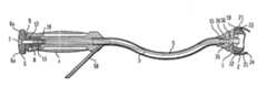
- FIG. 1is a side elevation of a prosthetic acetabular cup inserter but without an adjustable cup holder;
- FIG. 2is a plan view of the cup inserter shown in FIG. 1 ;
- FIG. 3is a cross-sectional side elevation of the other side of the inserter from that shown in FIG. 1 and with the adjustable cup holder in place on a prosthetic acetabular cup;
- FIG. 4is an enlarged cross-sectional elevation of part of the inserter shown in FIGS. 1 to 3 ;
- FIG. 5is a plan view of the elongated flexible element used in the construction shown in FIG. 3 ;
- FIG. 6is a pictorial isometric view from the other end of the elongated flexible element as shown in FIG. 5 ;
- FIGS. 7 to 11are pictorial isometric views showing how the various parts of the adjustable cup holder are assembled together;
- FIG. 12is an isometric view of an alternative construction of part of the adjustable cup holder
- FIG. 13is a pictorial exploded isometric view of the various parts of another alternative construction of adjustable cup holder
- FIG. 14is an isometric view showing the adjustable cup holder shown in FIG. 13 ready to receive the acetabular cup with which it is to be used;
- FIG. 15is another isometric view of the adjustable cup holder shown in FIG. 13 ready to receive the acetabular cup;
- FIG. 16is an isometric view of the adjustable cup holder shown in FIGS. 1 to 12 or 12 to 15 ;
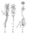
- FIG. 17is a cross-sectional side elevation of part of another alternative construction.
- FIG. 18is a plan view from above of the construction shown in FIG. 17 ;
- FIG. 19is an isometric view of the construction shown in FIGS. 17 and 18 ;
- FIG. 20is a sectional side elevation of an alternative construction with an operating trigger lever in a free position and in which the handle can receive the adjustable cup holder;
- FIG. 21is a view similar to FIG. 20 of the same construction with the operating trigger lever in a position to cause a first tension to hold the adjustable cup holder in position;
- FIG. 22is a view similar to FIGS. 20 and 21 of the same construction with the operating trigger lever in a position to grasp the cup to be inserted;
- FIG. 23is a exploded isometric view of the various parts which make up an alternative construction of an adjustable cup holder
- FIG. 24shows the parts illustrated in FIG. 23 assembled together and ready for assembly onto a shaped end piece on the handle and stem;
- FIG. 25shows the parts shown in FIGS. 23 and 24 in position and ready for rotation to a locked position
- FIG. 26shows the parts locked in position on the handle and stem
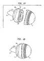
- FIG. 27is an isometric view of the parts shown in FIGS. 23 to 26 in position on the handle and stem and ready to receive the acetabular cup which is to be used;
- FIG. 28is a view similar to view 27 with the acetabular cup in place on the inserter.
- the preferred prosthetic acetabular cup insertercomprises an adjustable cup holder 1 which can be operated to grasp the cup 2 with which it is to be used from a position remote from the cup holder 1 through an elongated flexible element 3 which is in the form of a steel cable.
- the adjustable cup holder 1is carried on an operating handle 4 which can be rubberized and from which the flexible element 3 is operated.
- the free end of handle 4may have a knob 6 with a striker area 6 a .
- the handle 4is connected to the adjustable cup holder by a hollow extension 5 within which the flexible element 3 is carried.
- the extensionis of a curved shape to assist the surgeon during surgery.
- a tension forceis applied to the flexible element 3 by an operating element 6 which is in the form of a grooved knob and which has a screw threaded axial bore 7 .
- An extended portion 8 of the knob 6is located in a top hat shaped bearing 9 and in which it can freely rotate.
- the inner end of the bearing 9is closed but has a shaped bore 10 , provided with three flats which are angularly spaced apart by 120°, and within which a shaped nipple 11 (shown in FIGS. 5 and 6 ) provided on the flexible element 3 can slide but not rotate. From FIGS.
- the shaped nippleis substantially cylindrical apart from a set of three flats 12 which are angularly spaced apart by 120° and this portion of the nipple 11 also carries a screw thread which can co-operate with the screw thread in the bore 7 on the operating knob 6 .
- rotation of the operating knob 6will cause the screw threaded nipple to move backwards and forwards in the screw threaded bore 7 and it is held against rotation by the flats 12 acting against the flats in shaped bore 10 in the bearing 9 .
- Rotational movement of the knob 6can therefore be in a direction to create a tensional force in the flexible element 3 .
- a ring 13is provided in a groove 14 which holds it in place when the flexible element 3 is not assembled, but which can be dismantled for cleaning.
- the end of the extension 5 spaced away from the handle 4includes a substantially conically shaped end piece 15 which is rigidly secured to the hollow extension 5 .
- the end piece 15has a flat substantially circular bearing surface 16 which is provided with a pair of spaced apart shaped abutments 17 and which are arranged diametrically opposed to each other on each side of a bore 18 which communicates with the bore of the hollow extension 5 .
- a backing member in the form of a pressure plate 19has a shaped opening 20 adapted to fit over the abutments 17 which act to prevent plate 19 from rotating on the end piece 15 .
- the backing plate 19has an outer rim 21 which is shaped and adapted to align with the outer rim 22 of the acetabular cup shell to be inserted.
- the inner edge of the outer rim 21 of the plate 19is shaped to receive a resiliently deformable member in the form of a flexible ring 23 . This can be square, rectangular or circular shaped as required.
- the outer diameter of flexible ring 23is very slightly less than the inner diameter of the rim 22 of the cup 2 so that it can extend over it.
- the flexible ring 23is located on a movable operating member 24 which has an outer rim 25 shaped to extend over and engage the outer rim of the ring 23 .
- the movable operating member 24is also provided with a shaped opening 26 and which is of substantially the same shape and dimensions as the opening 20 in the backing member 19 .
- the end of the flexible element 3 displaced from the nipple 11carries a shaped locking head 30 which has a shaped part-circular collar 31 and a cylindrical stem portion 32 .
- the locking head 30has a bore 36 which also extends through the cylindrical portion 32 and the outer end of which is substantially rectangular. This engages with a substantially rectangular nipple 35 (and shown in FIG. 3 ) and prevents the head 30 from rotating on the element 5 .
- the collar 31is shaped to locate within the abutment 17 with its flat sides 37 aligned with the edges 38 of the abutments, as will be clearly seen from FIG.
- the spring 33engages against a shoulder 39 in the bore 36 in the conically shaped end 15 so that the head 31 is biased outwardly from the extension 5 into the position shown in FIG. 9 .
- FIG. 7shows the end piece 15 ready to receive the flexible element 3 . This is inserted so that the end carrying the nipple 11 is pushed through the extension and handle and until it engages with the screw threaded bore 7 in the operating knob 6 . Rotation of the operating knob in the appropriate direction now causes the nipple 11 to move up the bore 7 .
- the backing plate 19can be added by passing it over the projections 17 where it also acts to prevent rotation of the collar 31 as shown in FIG. 9 .
- the movable operating member 24is now placed in position, as indicated in FIG. 10 , and is then rotated through 90° so that its opening 26 lies at right angles to the head 31 and thus locks the assembly together, as shown in FIG. 11 .
- the cup 2 to be insertedWith the parts in the position indicated above the cup 2 to be inserted is placed over the rim of the ring 23 and the operating knob 6 is rotated appropriately which causes a tension and axial movement of the flexible element 3 thus pulling the movable operating member 24 against the resiliently deformable ring 23 so that it is compressed and is forced radially outwardly against the inner surface of the outer edge of the cup thus grasping the rim of the cup and holding it in position in relation to the inserter, as shown in FIG. 3 .
- the cupcan now be inserted in the acetabulum as required and the cup can also be held in this position if impaction is required.
- FIG. 12shows an alternative embodiment in which the same reference numerals are used to indicate similar parts but in this arrangement the shaped abutments 17 are of different dimensions, one, 17 ′, being larger than the other.
- the shaped opening 20is shaped to accommodate the abutments 17 to ensure that the pressure plate 19 can only be fitted in one predetermined position.
- This constructionis for use with prosthetic cups which have a particular anatomic shape and which require insertion in a particular position in the acetabulum.
- FIGS. 13 , 14 and 15show an alternative embodiment in which the same principles are employed as that set forth in FIGS. 1 to 12 but in this construction the adjustable cup holder is designed to operate with a cup 40 which has an internal groove 41 displaced inwardly from its immediate inner rim which carries a ring of depressions.
- the shape of the conical end 15 of the apparatusis similar to that described with regard to FIGS. 1 to 12 but the shaped head 30 on the flexible element 3 is replaced by a head carrying a pair of cylindrical abutments 42 .
- a backing or pressure member 43 of similar construction to but of different shape to that shown in FIG. 9is employed and located on this is a circlip or split ring 44 which replaces the deformable ring 23 shown in FIGS.
- the circlipcan be made of metal or any other suitable material.
- the removable operating member in this constructionis in the form of a dished member 45 which has a conical outer wall 46 and a shaped opening 47 which is dimensioned to pass over the abutments 42 .
- the shape of the abutments 17can be as shown in FIG. 12 .
- the assemblyis placed together in a similar manner to that described with regard to the earlier construction and the removable operating member 45 is again rotated through 90° to hold it in position.
- the flexible element 3again acts to pull the removable operating member 45 towards the backing member 43 but in this case the tapered sides of the operating member engage the inner surface 48 of circlip 44 forcing it apart.
- the cup 40is placed on the assembly operation of the flexible element 3 causes the circlip 44 to expand into the groove 41 on the cup 40 and thus hold it in position.
- the cupcan be released by again operating the knob 6 .
- a guide 50can also be provided on or adjacent the handle to assist the surgeon.
- FIG. 16shows how the rear face of the pressure plate 19 can be marked with a landmark 55 to indicate the position of a trial cup (not shown) to the definitive cup 2 to be inserted using a bistoury marking on the rim of the acetabulum.
- Reference numeral 56indicates an area to position the trial cup following the anterial rim of the acetabulum. The markings are desirable for use with cups which have a particularly shaped rim.
- FIGS. 17 to 19show another alternative construction in which the same reference numerals are used to indicate similar parts to those shown in FIGS. 1 to 12 .
- a trigger mechanismis employed the pivotal movement of which is used to tension the flexible element 3 .
- the trigger mechanismcomprises an operating trigger lever 60 which is located within a slot 61 in the handle 4 and carried on a pivot pin 62 which extends transversely across the handle 4 .
- the trigger lever 61has a pair of flanges 64 each of which has a bore 65 to accept one of the pivot pin 62 .
- the flanges 64each have a cam surface 66 which extends around the end of the trigger lever 60 .
- Cam surfaces 66bear against a cylindrical bearing block 67 carried on an adjustment hand wheel 68 .
- the hand wheel 68has an extension 69 which locates in a bearing bore 70 provided in a handle end cap 71 .
- the end of the flexible element 3is provided with a screw threaded nipple 72 which is carried in a screw threaded bore 73 in the adjusting wheel 68 and extends through an opening 74 in the pivot pin 62 and between the cam flanges 64 .
- the adjustable cup holder 1can be similar to that shown in FIGS. 1 to 12 and the flexible element 3 can be attached in a similar manner, preferably however an alternate cup holder construction is used which is shown in FIGS. 19 to 28 as further described below.
- the triggeris first lifted to the position shown in FIG. 19 . In this position the height of the cam surface is their lowest so that there is the maximum relaxation of the flexible element 3 . This enables the cup to be placed in position on the cup holder.
- the leveris now rotated in an anticlockwise direction when viewed in FIG. 17 which moves the cam surfaces round their highest position which in turn forces the bearing block 67 towards the right (as shown in FIG. 17 ) thus tensioning the flexible element 3 which is connected to the bearing block 67 and the hand wheel 68 , the axial movement being accommodated in the bore 70 .
- the tension of the flexible element 3is sufficient for the flexible ring 23 in the cup holder 1 to grasp the cup.
- the trigger mechanismcan also be employed with the cup holder construction shown in FIGS. 13 to 16 .
- the applied tension at the closed position of the triggercan be adjusted by rotating the hand wheel 68 .
- Thiscan be rotated on the threaded nipple 72 which will cause the nipple to move axially in either direction depending upon the direction of rotation of the hand wheel.
- the effectis to vary the operative length of the flexible element 3 and to increase or decrease the applied tension.
- the hand wheelcan thus be used when different sized cups are employed which, depending upon their dimensions, may require slightly more or less movement of the resilient ring to grasp the cup.
- the trigger mechanismcan include a locking mechanism to allow it to be locked in the position shown in FIG. 17 .
- Thisfor example, can be in the form of a simple rotating clasp indicated by reference numeral 78 and shown in broken lines in FIG. 18 .
- FIGS. 20 and 22show a construction in which the same reference numerals are used to indicate similar parts as in FIGS. 17 to 19 and the constructions of the handle 4 is generally similar to that described in FIGS. 17 , 18 and 19 but the operating trigger lever can be moved to three operative positions.
- the operating trigger leveris indicated by reference numeral 81 and its cams, indicated by reference numeral 82 , have three operating surfaces, indicated by reference numerals 83 , 84 and 85 respectively.
- FIG. 20shows the operating trigger lever 81 in a first position where the cam surface 83 bears against the cylindrical bearing block 67 on the hand wheel 68 .
- the flexible elementcan be assembled onto the handle.
- the hand wheel 68is tightened up to the cam surface 83 and the operating trigger lever 81 is then moved to the second position, as shown in FIG. 21 , and the second cam surface 84 bears against the cylindrical bearing block 67 .
- This cam surfaceis 1.5 mm lower than cam surface 83 and allows the adjustable cup holder assembly to be fitted to the end piece of the extension 5 and for the locking head 30 to be located in place.
- the assemblyis now ready to receive the cup with which it is to be used.
- the operating trigger lever 81When the cup is placed in position on the adjacent cup holder 1 the operating trigger lever 81 is moved to the third position as shown in FIG. 22 . This causes cam surface 85 to engage the cylindrical bearing block 67 and thus tension the flexible element 3 .
- the cam surface 85is 1 mm higher than the cam surface 84 and this provides sufficient tensioning in the flexible element 3 to compress the flexible ring 23 to cause it to expand and grasp the rim of the cup.
- the operating trigger lever 81is moved back to the position shown in FIG. 21 which allows the release of the inserter from the cup and the operating trigger lever can be moved further counterclockwise to a position shown in FIG. 20 to allow the various parts of the cup holder 1 to be released from the end piece 15 .
- FIGS. 17 to 21can be used with the arrangements shown in FIGS. 7 to 15 .
- FIGS. 19 to 28show an alternative form of releasable cup holder which can not only be used with the construction shown in FIGS. 17 to 22 but also with the arrangement shown in FIGS. 1 to 8 .
- the releasable cup holdercomprises a backing member 90 which has an outer rim 91 shaped and adapted to align with the outer rim of the acetabular cup to be inserted.
- the backing member 90is adapted for use with an end piece 92 as shown in FIGS. 19 , 24 , 25 and 26 .
- This end piecewhich is rigidly secured to the hollow extension 5 , has a substantially flat circular bearing surface 93 similar to the bearing surface 16 of the construction shown in FIGS. 7 and 8 . It also has a pair of spaced apart shaped abutments 94 which are arranged diametrically opposed to each other on each side of a bore which communicated through the bore of the hollow extension 5 .
- the end piece 92has a projection 95 adjacent its outer rim and best seen in FIGS. 24 , 25 and 26 and a shaped locking head 30 , similar to that shown in the other constructions, is also provided.
- the backing member 90has a first radial groove 96 from which extends a ramp 97 . This terminates in a flat circumferentially extending surface 98 and leads to a second radially extending groove 99 with which is aligned a cut-out 100 .
- the movable operating member 110 in this constructioncomprises a flanged circular plate 111 the flange 112 having a radially projecting rim 113 .
- a shaped opening 114similar to the shaped opening 26 in the construction shown in FIGS. 7 to 12 , is provided and the circular plate 111 has a projecting pin 115 .
- the flexible element 120 in this arrangementis shaped to extend over the flange 112 and rest against the outer rim 113 .
- This constructionis assembled by placing the flexible element 120 in position on the flange 112 and pushing the operating member 110 onto the backing member 90 , at the same time engaging the pin 115 in a bore 116 in the backing member. It will be appreciated that the pin 115 aligns and holds the parts together.
- the assembled partsare presented to the end piece 92 as shown in FIG. 24 and then pressed against the end piece 92 as shown in FIG. 25 .
- the flexible elementis dimensioned so that it is slightly compressed when the parts are pushed into positions as shown in FIG. 25 with first groove 96 aligned with the projection 95 on the end piece 92 .
- the partsare now rotated in the direction of the arrow shown in FIG. 25 moving the projection 95 up the ramp 97 and around until it engages the second groove 99 as shown in FIG. 26 .
- the operating trigger lever 81 of the construction shown in FIG. 19 or FIGS. 20 to 22is moved to the free position.
- the hand wheel 68is rotated to a position in which there is maximum movement and the handle is then closed which produces a reduced tension force and enables the end piece 30 , which has been passed through a circular opening 121 in the backing member 90 and through the shaped opening 114 in the movable operating member 110 which acts to hold the parts in position.
- this positionis achieved by moving the operating trigger lever 81 to its first tension position.
- the inserteris now assembled and ready to receive the cup 2 with which it is to be used.
- the shaped cupis aligned with the shaped edge 91 of the backing member 90 as shown n FIG. 27 .
- the cupis then placed onto the cup holder 1 as shown in FIG. 28 with the flexible element within the outer rim of the cup in a similar manner to that described with the earlier embodiments.
- the adjustment hand wheelWhen used with the arrangement shown in FIGS. 17 to 19 the adjustment hand wheel is adjusted to provide maximum tension in the flexible element 3 and operating trigger level 60 is then moved to provide the maximum tension of the flexible elements 3 which thus acts to expand the flexible ring 120 by compressing it between the backing member 90 and the operating member 110 , the ring thus expanding radially to grasp the cup 2 .
- the flexible ring 23now performs two functions. It not only provides a resilient bias to hold the parts in position when they are first located on the end piece 92 but, on further compression, it also acts to grasp the cup 2 .
- a number of alternative cup holderscan be provided of different dimensions for use with cups of different dimensions so that a modular construction is achieved.
- one handle and extensioncan be used with a large number of different shaped and sizes adjustable cup holders.
- the various partscan be made from any convenient material, for example the various parts of the adjustable cup holder can be made from metal or a synthetic plastics material. Again, the handle and extension can be metal or a synthetic plastics material as can the end piece. It is also possible to use different materials for the other parts, for example the flexible element could be made from a suitably strong synthetic material as well as from metal.
Landscapes
- Health & Medical Sciences (AREA)
- Transplantation (AREA)
- Orthopedic Medicine & Surgery (AREA)
- Heart & Thoracic Surgery (AREA)
- Cardiology (AREA)
- Oral & Maxillofacial Surgery (AREA)
- Engineering & Computer Science (AREA)
- Biomedical Technology (AREA)
- Physical Education & Sports Medicine (AREA)
- Vascular Medicine (AREA)
- Life Sciences & Earth Sciences (AREA)
- Animal Behavior & Ethology (AREA)
- General Health & Medical Sciences (AREA)
- Public Health (AREA)
- Veterinary Medicine (AREA)
- Prostheses (AREA)
Abstract
Description
Claims (32)
Applications Claiming Priority (2)
| Application Number | Priority Date | Filing Date | Title |
|---|---|---|---|
| GB0405059.7 | 2004-03-05 | ||
| GBGB0405059.7AGB0405059D0 (en) | 2004-03-05 | 2004-03-05 | Prosthetic acetabular cup inserter |
Publications (2)
| Publication Number | Publication Date |
|---|---|
| US20050228395A1 US20050228395A1 (en) | 2005-10-13 |
| US7341593B2true US7341593B2 (en) | 2008-03-11 |
Family
ID=32088824
Family Applications (1)
| Application Number | Title | Priority Date | Filing Date |
|---|---|---|---|
| US11/072,583Expired - LifetimeUS7341593B2 (en) | 2004-03-05 | 2005-03-04 | Prosthetic acetabular cup inserter |
Country Status (5)
| Country | Link |
|---|---|
| US (1) | US7341593B2 (en) |
| EP (1) | EP1570815B1 (en) |
| AU (1) | AU2005200995B2 (en) |
| CA (1) | CA2499337C (en) |
| GB (1) | GB0405059D0 (en) |
Cited By (30)
| Publication number | Priority date | Publication date | Assignee | Title |
|---|---|---|---|---|
| US20070173856A1 (en)* | 2006-01-25 | 2007-07-26 | Parker Brad A | Split thread orthopaedic implant impactor |
| US20090099566A1 (en)* | 2007-10-10 | 2009-04-16 | Maness Megan A | Modular stem inserter |
| US20100032090A1 (en)* | 2008-08-05 | 2010-02-11 | David Myung | Polyurethane-Grafted Hydrogels |
| US20100106159A1 (en)* | 2006-05-01 | 2010-04-29 | Greatbatch Medical Sa | Inserter For Minimally Invasive Joint Surgery Having an Interchangeable Prosthesis Engaging Piston |
| US20110152868A1 (en)* | 2009-12-18 | 2011-06-23 | Lampros Kourtis | Method, device, and system for shaving and shaping of a joint |
| US20110184423A1 (en)* | 2010-01-25 | 2011-07-28 | Howmedica Osteonics Corp. | Inserter for locating and impacting an acetabular cup |
| US8277457B1 (en) | 2004-12-09 | 2012-10-02 | Greatbatch Medical S.A. | Orthopaedic inserter using a collet mechanism |
| US8398650B1 (en) | 2009-01-27 | 2013-03-19 | Greatbatch Medical S.A. | Offset cup impactor with an expandable dome for double mobility implants |
| WO2013078284A1 (en)* | 2011-11-21 | 2013-05-30 | Biomimedica, Inc. | Systems, devices, and methods for anchoring orthopaedic implants to bone |
| US8585709B2 (en) | 2011-01-17 | 2013-11-19 | Greatbatch Medical S.A. | Straight cup impactor with lever arm |
| US8679190B2 (en) | 2004-10-05 | 2014-03-25 | The Board Of Trustees Of The Leland Stanford Junior University | Hydrogel arthroplasty device |
| US8834479B2 (en) | 2010-11-25 | 2014-09-16 | Stryker Ireland Limited | Prosthetic acetabular cup inserter and impactor |
| US8870886B2 (en) | 2011-08-26 | 2014-10-28 | Greatbatch Medical S.A. | Straight cup impactor |
| US8883915B2 (en) | 2008-07-07 | 2014-11-11 | Biomimedica, Inc. | Hydrophobic and hydrophilic interpenetrating polymer networks derived from hydrophobic polymers and methods of preparing the same |
| US8894660B2 (en) | 2010-11-25 | 2014-11-25 | Stryker Ireland Limited | Acetabular cup inserter and impactor |
| US8900245B2 (en)* | 2012-06-07 | 2014-12-02 | Howmedica Osteonics Corp. | Glenosphere inserter and impactor |
| US8961528B2 (en) | 2010-08-27 | 2015-02-24 | Greatbatch Medical S.A. | Offset cup impactor with a grasping plate for double mobility implants |
| US9028502B2 (en) | 2011-09-23 | 2015-05-12 | Greatbatch Medical S.A. | Ceramic implant holder |
| US9119731B2 (en) | 2011-01-17 | 2015-09-01 | Greatbach Medical S.A. | Straight cup impactor |
| US9144496B2 (en) | 2012-04-23 | 2015-09-29 | Zimmer, Inc. | Inserter connection member |
| US20160135862A1 (en)* | 2014-11-17 | 2016-05-19 | Spinal Elements, Inc. | Curved surgical tools |
| US10457803B2 (en) | 2008-07-07 | 2019-10-29 | Hyalex Orthopaedics, Inc. | Orthopedic implants having gradient polymer alloys |
| RU2715458C2 (en)* | 2015-04-28 | 2020-02-28 | Депью Айэлэнд Анлимитед Компани | Device and method of liner insertion into acetabular cup |
| US10792392B2 (en) | 2018-07-17 | 2020-10-06 | Hyalex Orthopedics, Inc. | Ionic polymer compositions |
| US10842650B2 (en)* | 2012-03-30 | 2020-11-24 | DePuy Synthes Products, Inc. | Implant insertion tool for use in a surgical procedure to implant a stemless humeral component |
| US11015016B2 (en) | 2011-10-03 | 2021-05-25 | Hyalex Orthopaedics, Inc. | Polymeric adhesive for anchoring compliant materials to another surface |
| US11077228B2 (en) | 2015-08-10 | 2021-08-03 | Hyalex Orthopaedics, Inc. | Interpenetrating polymer networks |
| KR20230037124A (en) | 2021-09-08 | 2023-03-16 | 주식회사 코렌텍 | Acetabular Cup Impactor, Anteversion Guide and Surgical Instrument thereof |
| KR20230041222A (en) | 2021-09-17 | 2023-03-24 | (주) 해리아나 | Differential Pressure Transmitter and the Method of Measuring Differential Pressure |
| US12064356B2 (en) | 2021-08-19 | 2024-08-20 | Howmedica Osteonics Corp. | Multi-size acetabular impactor |
Families Citing this family (37)
| Publication number | Priority date | Publication date | Assignee | Title |
|---|---|---|---|---|
| US20020120340A1 (en) | 2001-02-23 | 2002-08-29 | Metzger Robert G. | Knee joint prosthesis |
| US7497874B1 (en) | 2001-02-23 | 2009-03-03 | Biomet Manufacturing Corp. | Knee joint prosthesis |
| DE102004042183A1 (en)* | 2004-06-22 | 2006-01-19 | Plus Endoprothetik Ag | Device for setting or removing joints or joint sockets |
| WO2006058221A2 (en) | 2004-11-24 | 2006-06-01 | Abdou Samy M | Devices and methods for inter-vertebral orthopedic device placement |
| US7682363B2 (en)* | 2004-12-09 | 2010-03-23 | Greatbatch Medical S.A. | Inserter for minimally invasive joint surgery |
| US8034080B2 (en) | 2005-02-17 | 2011-10-11 | Kyphon Sarl | Percutaneous spinal implants and methods |
| US20070276373A1 (en)* | 2005-02-17 | 2007-11-29 | Malandain Hugues F | Percutaneous Spinal Implants and Methods |
| US8096995B2 (en) | 2005-02-17 | 2012-01-17 | Kyphon Sarl | Percutaneous spinal implants and methods |
| US8096994B2 (en) | 2005-02-17 | 2012-01-17 | Kyphon Sarl | Percutaneous spinal implants and methods |
| US7976548B2 (en)* | 2005-08-24 | 2011-07-12 | Greatbatch Medical S.A. | Surgical tool holder for facilitated sterilization |
| DE102005041062A1 (en)* | 2005-08-30 | 2007-03-01 | Plus Orthopedics Ag | Device used for manipulation of artificial hip joint, comprises pressure relief valve operated with switch located at handle |
| US8425526B2 (en)* | 2006-10-17 | 2013-04-23 | Smith & Nephew, Inc. | Adjustable impactor |
| US8562616B2 (en) | 2007-10-10 | 2013-10-22 | Biomet Manufacturing, Llc | Knee joint prosthesis system and method for implantation |
| JP5448842B2 (en) | 2007-01-10 | 2014-03-19 | バイオメト マニファクチャリング コーポレイション | Knee joint prosthesis system and implantation method |
| US8163028B2 (en) | 2007-01-10 | 2012-04-24 | Biomet Manufacturing Corp. | Knee joint prosthesis system and method for implantation |
| US8328873B2 (en) | 2007-01-10 | 2012-12-11 | Biomet Manufacturing Corp. | Knee joint prosthesis system and method for implantation |
| US8187280B2 (en) | 2007-10-10 | 2012-05-29 | Biomet Manufacturing Corp. | Knee joint prosthesis system and method for implantation |
| GB0702945D0 (en) | 2007-02-15 | 2007-03-28 | Depuy Ireland Ltd | An instrument for gripping a cup component of a joint prosthesis |
| US8016832B2 (en)* | 2007-05-02 | 2011-09-13 | Zimmer Spine, Inc. | Installation systems for spinal stabilization system and related methods |
| GB0808284D0 (en) | 2008-05-07 | 2008-06-11 | Benoist Girard Sas | |
| US8764806B2 (en) | 2009-12-07 | 2014-07-01 | Samy Abdou | Devices and methods for minimally invasive spinal stabilization and instrumentation |
| US8147526B2 (en) | 2010-02-26 | 2012-04-03 | Kyphon Sarl | Interspinous process spacer diagnostic parallel balloon catheter and methods of use |
| US8845728B1 (en) | 2011-09-23 | 2014-09-30 | Samy Abdou | Spinal fixation devices and methods of use |
| US20130226240A1 (en) | 2012-02-22 | 2013-08-29 | Samy Abdou | Spinous process fixation devices and methods of use |
| US9198767B2 (en) | 2012-08-28 | 2015-12-01 | Samy Abdou | Devices and methods for spinal stabilization and instrumentation |
| US9320617B2 (en) | 2012-10-22 | 2016-04-26 | Cogent Spine, LLC | Devices and methods for spinal stabilization and instrumentation |
| CN112773580B (en) | 2015-07-27 | 2024-06-18 | 黑普创新技术有限责任公司 | Ball and cup impactor for implanting hip joint prosthesis |
| US10857003B1 (en) | 2015-10-14 | 2020-12-08 | Samy Abdou | Devices and methods for vertebral stabilization |
| GB201521501D0 (en)* | 2015-12-07 | 2016-01-20 | Depuy Ireland | Apparatus and method for aligning an acetabular cup |
| CN106983587B (en)* | 2016-01-20 | 2019-03-15 | 北京纳通科技集团有限公司 | Using prosthesis instrument |
| US10973648B1 (en) | 2016-10-25 | 2021-04-13 | Samy Abdou | Devices and methods for vertebral bone realignment |
| US10744000B1 (en) | 2016-10-25 | 2020-08-18 | Samy Abdou | Devices and methods for vertebral bone realignment |
| US10874406B2 (en)* | 2017-02-28 | 2020-12-29 | MFr Technologies, Inc. | Handheld surgical instrument |
| US11179248B2 (en) | 2018-10-02 | 2021-11-23 | Samy Abdou | Devices and methods for spinal implantation |
| EP3682820B1 (en)* | 2019-01-18 | 2022-06-29 | Shukla Medical | Striking assembly and surgical tool assembly |
| FR3136961A1 (en)* | 2022-06-22 | 2023-12-29 | Euros | Instrument for manipulating and impacting a hip prosthesis cup |
| WO2025141612A1 (en)* | 2023-12-28 | 2025-07-03 | Meril Healthcare Pvt. Ltd. | Ceramic liner inserter |
Citations (30)
| Publication number | Priority date | Publication date | Assignee | Title |
|---|---|---|---|---|
| US3859992A (en)* | 1973-06-06 | 1975-01-14 | Harlan C Amstutz | Vacuum-operated acetabular cup holder and positioner |
| US4293962A (en) | 1980-02-14 | 1981-10-13 | Zimmer Usa, Inc. | Bone plug inserting system |
| US4305394A (en) | 1980-12-22 | 1981-12-15 | Bertuch Jr Charles J | Acetabular cup positioning instrument |
| US4632111A (en) | 1985-03-21 | 1986-12-30 | Minnesota Mining And Manufacturing Company | Acetabular cup positioning apparatus |
| US5116339A (en) | 1990-07-11 | 1992-05-26 | Glock Steven R | Acetabular cup installation tool and method of installing an acetabular cup |
| US5169399A (en) | 1991-10-17 | 1992-12-08 | Boehringer Mannheim Corporation | Acetabular cup impactor |
| US5395188A (en) | 1993-12-23 | 1995-03-07 | Roy E. Bowling | Guide for angled and curved drilling |
| US5486181A (en)* | 1994-08-04 | 1996-01-23 | Implex Corporation | Acetabular cup, method and tool and installing the same |
| US5540697A (en) | 1993-02-12 | 1996-07-30 | U.S. Medical Products, Inc. | Prosthetic socket installation apparatus and method |
| US5571111A (en) | 1995-05-01 | 1996-11-05 | Aboczky; Robert I. | Instrument for orienting, inserting and impacting an acetabular cup prosthesis including prosthesis retaining head arrangement |
| US5683399A (en) | 1995-12-01 | 1997-11-04 | Stelkast Incorporated | Acetabular cup insertion tool |
| US5902107A (en) | 1996-11-14 | 1999-05-11 | Lowell; Jeremy | Disposable prophylaxis angle with adjustable head |
| US5908423A (en) | 1993-05-27 | 1999-06-01 | Howmedica, Inc. | Flexible medullary reaming system |
| US5928287A (en)* | 1996-05-09 | 1999-07-27 | Waldemar Link (Gmbh & Co.) | Acetabular cup and surgical instrument for implanting same |
| US5954727A (en) | 1993-10-29 | 1999-09-21 | Howmedica Inc. | Acetabular cup positioning tool and method of positioning an acetabular cup |
| US6022357A (en)* | 1997-03-03 | 2000-02-08 | Aesculap Ag & Co. Kg | Surgical instrument |
| US6063124A (en) | 1999-03-01 | 2000-05-16 | Amstutz; Harlan C. | Acetabular cup prosthesis insertion and removal assembly and technique |
| US6093184A (en) | 1995-03-23 | 2000-07-25 | Sulzer Carbomedics Inc. | Flexible valve rotator |
| US6174313B1 (en) | 1990-06-28 | 2001-01-16 | Peter M. Bonutti | Apparatus and method for tissue removal |
| WO2001006964A1 (en) | 1999-07-27 | 2001-02-01 | Bo Tillander | Directing and compression instrument |
| US6200306B1 (en) | 1999-05-26 | 2001-03-13 | Sulzer Carbomedics Inc. | Bend clip for flexible rotator |
| US6447518B1 (en) | 1995-07-18 | 2002-09-10 | William R. Krause | Flexible shaft components |
| US6468281B1 (en)* | 1998-04-30 | 2002-10-22 | Ceramtec Ag | Instrument for manipulating components of joint prostheses |
| US20030050645A1 (en) | 2002-10-30 | 2003-03-13 | Parker Brad A. | Acetabular cup impactor |
| US6613085B1 (en) | 1996-01-31 | 2003-09-02 | St. Jude Medical, Inc. | Prosthetic heart valve rotator tool |
| US20030229356A1 (en) | 2002-06-10 | 2003-12-11 | Donald Dye | Curved acetabular shell impaction instrument and method of use |
| WO2004010882A1 (en) | 2002-07-25 | 2004-02-05 | Enztec Limited | Surgical impactor with workpiece engageable head |
| US20040153063A1 (en) | 2003-02-04 | 2004-08-05 | Harris Brian R. | Acetabular impactor |
| US20040186586A1 (en) | 2003-02-04 | 2004-09-23 | Seyer Steven F. | Acetabular component insertion and extraction tool for use therewith, and method of locking an acetabular component to an insertion and extraction tool |
| US20060149285A1 (en)* | 2004-12-09 | 2006-07-06 | Precimed S.A. | Inserter for minimally invasive joint surgery |
- 2004
- 2004-03-05GBGBGB0405059.7Apatent/GB0405059D0/ennot_activeCeased
- 2005
- 2005-03-04EPEP05251303.3Apatent/EP1570815B1/ennot_activeExpired - Lifetime
- 2005-03-04AUAU2005200995Apatent/AU2005200995B2/ennot_activeCeased
- 2005-03-04CACA2499337Apatent/CA2499337C/ennot_activeExpired - Fee Related
- 2005-03-04USUS11/072,583patent/US7341593B2/ennot_activeExpired - Lifetime
Patent Citations (30)
| Publication number | Priority date | Publication date | Assignee | Title |
|---|---|---|---|---|
| US3859992A (en)* | 1973-06-06 | 1975-01-14 | Harlan C Amstutz | Vacuum-operated acetabular cup holder and positioner |
| US4293962A (en) | 1980-02-14 | 1981-10-13 | Zimmer Usa, Inc. | Bone plug inserting system |
| US4305394A (en) | 1980-12-22 | 1981-12-15 | Bertuch Jr Charles J | Acetabular cup positioning instrument |
| US4632111A (en) | 1985-03-21 | 1986-12-30 | Minnesota Mining And Manufacturing Company | Acetabular cup positioning apparatus |
| US6174313B1 (en) | 1990-06-28 | 2001-01-16 | Peter M. Bonutti | Apparatus and method for tissue removal |
| US5116339A (en) | 1990-07-11 | 1992-05-26 | Glock Steven R | Acetabular cup installation tool and method of installing an acetabular cup |
| US5169399A (en) | 1991-10-17 | 1992-12-08 | Boehringer Mannheim Corporation | Acetabular cup impactor |
| US5540697A (en) | 1993-02-12 | 1996-07-30 | U.S. Medical Products, Inc. | Prosthetic socket installation apparatus and method |
| US5908423A (en) | 1993-05-27 | 1999-06-01 | Howmedica, Inc. | Flexible medullary reaming system |
| US5954727A (en) | 1993-10-29 | 1999-09-21 | Howmedica Inc. | Acetabular cup positioning tool and method of positioning an acetabular cup |
| US5395188A (en) | 1993-12-23 | 1995-03-07 | Roy E. Bowling | Guide for angled and curved drilling |
| US5486181A (en)* | 1994-08-04 | 1996-01-23 | Implex Corporation | Acetabular cup, method and tool and installing the same |
| US6093184A (en) | 1995-03-23 | 2000-07-25 | Sulzer Carbomedics Inc. | Flexible valve rotator |
| US5571111A (en) | 1995-05-01 | 1996-11-05 | Aboczky; Robert I. | Instrument for orienting, inserting and impacting an acetabular cup prosthesis including prosthesis retaining head arrangement |
| US6447518B1 (en) | 1995-07-18 | 2002-09-10 | William R. Krause | Flexible shaft components |
| US5683399A (en) | 1995-12-01 | 1997-11-04 | Stelkast Incorporated | Acetabular cup insertion tool |
| US6613085B1 (en) | 1996-01-31 | 2003-09-02 | St. Jude Medical, Inc. | Prosthetic heart valve rotator tool |
| US5928287A (en)* | 1996-05-09 | 1999-07-27 | Waldemar Link (Gmbh & Co.) | Acetabular cup and surgical instrument for implanting same |
| US5902107A (en) | 1996-11-14 | 1999-05-11 | Lowell; Jeremy | Disposable prophylaxis angle with adjustable head |
| US6022357A (en)* | 1997-03-03 | 2000-02-08 | Aesculap Ag & Co. Kg | Surgical instrument |
| US6468281B1 (en)* | 1998-04-30 | 2002-10-22 | Ceramtec Ag | Instrument for manipulating components of joint prostheses |
| US6063124A (en) | 1999-03-01 | 2000-05-16 | Amstutz; Harlan C. | Acetabular cup prosthesis insertion and removal assembly and technique |
| US6200306B1 (en) | 1999-05-26 | 2001-03-13 | Sulzer Carbomedics Inc. | Bend clip for flexible rotator |
| WO2001006964A1 (en) | 1999-07-27 | 2001-02-01 | Bo Tillander | Directing and compression instrument |
| US20030229356A1 (en) | 2002-06-10 | 2003-12-11 | Donald Dye | Curved acetabular shell impaction instrument and method of use |
| WO2004010882A1 (en) | 2002-07-25 | 2004-02-05 | Enztec Limited | Surgical impactor with workpiece engageable head |
| US20030050645A1 (en) | 2002-10-30 | 2003-03-13 | Parker Brad A. | Acetabular cup impactor |
| US20040153063A1 (en) | 2003-02-04 | 2004-08-05 | Harris Brian R. | Acetabular impactor |
| US20040186586A1 (en) | 2003-02-04 | 2004-09-23 | Seyer Steven F. | Acetabular component insertion and extraction tool for use therewith, and method of locking an acetabular component to an insertion and extraction tool |
| US20060149285A1 (en)* | 2004-12-09 | 2006-07-06 | Precimed S.A. | Inserter for minimally invasive joint surgery |
Cited By (45)
| Publication number | Priority date | Publication date | Assignee | Title |
|---|---|---|---|---|
| US9387082B2 (en) | 2004-10-05 | 2016-07-12 | The Board Of Trustees Of The Leland Stanford Junior University | Hydrogel arthroplasty device |
| US8679190B2 (en) | 2004-10-05 | 2014-03-25 | The Board Of Trustees Of The Leland Stanford Junior University | Hydrogel arthroplasty device |
| US8277457B1 (en) | 2004-12-09 | 2012-10-02 | Greatbatch Medical S.A. | Orthopaedic inserter using a collet mechanism |
| US8142439B2 (en) | 2006-01-25 | 2012-03-27 | Symmetry Medical Manufacturing, Inc. | Method of connecting an impactor to an orthopaedic implant |
| US20070173856A1 (en)* | 2006-01-25 | 2007-07-26 | Parker Brad A | Split thread orthopaedic implant impactor |
| US20100049257A1 (en)* | 2006-01-25 | 2010-02-25 | Symmetry Medical, Inc. | Split thread orthopaedic implant impactor |
| US7621921B2 (en)* | 2006-01-25 | 2009-11-24 | Symmetry Medical, Inc | Split thread orthopaedic implant impactor |
| US20100106159A1 (en)* | 2006-05-01 | 2010-04-29 | Greatbatch Medical Sa | Inserter For Minimally Invasive Joint Surgery Having an Interchangeable Prosthesis Engaging Piston |
| US8236004B2 (en) | 2006-05-01 | 2012-08-07 | Greatbatch Medical S.A. | Inserter for minimally invasive joint surgery having an interchangeable prosthesis engaging piston |
| US20090099566A1 (en)* | 2007-10-10 | 2009-04-16 | Maness Megan A | Modular stem inserter |
| US10457803B2 (en) | 2008-07-07 | 2019-10-29 | Hyalex Orthopaedics, Inc. | Orthopedic implants having gradient polymer alloys |
| US10752768B2 (en) | 2008-07-07 | 2020-08-25 | Hyalex Orthopaedics, Inc. | Orthopedic implants having gradient polymer alloys |
| US8883915B2 (en) | 2008-07-07 | 2014-11-11 | Biomimedica, Inc. | Hydrophobic and hydrophilic interpenetrating polymer networks derived from hydrophobic polymers and methods of preparing the same |
| US8497023B2 (en) | 2008-08-05 | 2013-07-30 | Biomimedica, Inc. | Polyurethane-grafted hydrogels |
| US20100032090A1 (en)* | 2008-08-05 | 2010-02-11 | David Myung | Polyurethane-Grafted Hydrogels |
| US8853294B2 (en) | 2008-08-05 | 2014-10-07 | Biomimedica, Inc. | Polyurethane-grafted hydrogels |
| US8398650B1 (en) | 2009-01-27 | 2013-03-19 | Greatbatch Medical S.A. | Offset cup impactor with an expandable dome for double mobility implants |
| US20110152868A1 (en)* | 2009-12-18 | 2011-06-23 | Lampros Kourtis | Method, device, and system for shaving and shaping of a joint |
| US8430886B2 (en) | 2010-01-25 | 2013-04-30 | Howmedica Osteonics Corp. | Inserter for locating and impacting an acetabular cup |
| US20110184423A1 (en)* | 2010-01-25 | 2011-07-28 | Howmedica Osteonics Corp. | Inserter for locating and impacting an acetabular cup |
| US8961528B2 (en) | 2010-08-27 | 2015-02-24 | Greatbatch Medical S.A. | Offset cup impactor with a grasping plate for double mobility implants |
| US8834479B2 (en) | 2010-11-25 | 2014-09-16 | Stryker Ireland Limited | Prosthetic acetabular cup inserter and impactor |
| US8894660B2 (en) | 2010-11-25 | 2014-11-25 | Stryker Ireland Limited | Acetabular cup inserter and impactor |
| US9119731B2 (en) | 2011-01-17 | 2015-09-01 | Greatbach Medical S.A. | Straight cup impactor |
| US8585709B2 (en) | 2011-01-17 | 2013-11-19 | Greatbatch Medical S.A. | Straight cup impactor with lever arm |
| US8870886B2 (en) | 2011-08-26 | 2014-10-28 | Greatbatch Medical S.A. | Straight cup impactor |
| US9028502B2 (en) | 2011-09-23 | 2015-05-12 | Greatbatch Medical S.A. | Ceramic implant holder |
| US11760830B2 (en) | 2011-10-03 | 2023-09-19 | Hyalex Orthopaedics, Inc. | Polymeric adhesive for anchoring compliant materials to another surface |
| US11015016B2 (en) | 2011-10-03 | 2021-05-25 | Hyalex Orthopaedics, Inc. | Polymeric adhesive for anchoring compliant materials to another surface |
| US9114024B2 (en) | 2011-11-21 | 2015-08-25 | Biomimedica, Inc. | Systems, devices, and methods for anchoring orthopaedic implants to bone |
| WO2013078284A1 (en)* | 2011-11-21 | 2013-05-30 | Biomimedica, Inc. | Systems, devices, and methods for anchoring orthopaedic implants to bone |
| US11980551B2 (en) | 2012-03-30 | 2024-05-14 | DePuy Synthes Products, Inc. | Implant insertion tool for use in a surgical procedure to implant a stemless humeral component |
| US10842650B2 (en)* | 2012-03-30 | 2020-11-24 | DePuy Synthes Products, Inc. | Implant insertion tool for use in a surgical procedure to implant a stemless humeral component |
| US9144496B2 (en) | 2012-04-23 | 2015-09-29 | Zimmer, Inc. | Inserter connection member |
| US8900245B2 (en)* | 2012-06-07 | 2014-12-02 | Howmedica Osteonics Corp. | Glenosphere inserter and impactor |
| US20160135862A1 (en)* | 2014-11-17 | 2016-05-19 | Spinal Elements, Inc. | Curved surgical tools |
| RU2715458C2 (en)* | 2015-04-28 | 2020-02-28 | Депью Айэлэнд Анлимитед Компани | Device and method of liner insertion into acetabular cup |
| US11077228B2 (en) | 2015-08-10 | 2021-08-03 | Hyalex Orthopaedics, Inc. | Interpenetrating polymer networks |
| US10869950B2 (en) | 2018-07-17 | 2020-12-22 | Hyalex Orthopaedics, Inc. | Ionic polymer compositions |
| US10792392B2 (en) | 2018-07-17 | 2020-10-06 | Hyalex Orthopedics, Inc. | Ionic polymer compositions |
| US11110200B2 (en) | 2018-07-17 | 2021-09-07 | Hyalex Orthopaedics, Inc. | Ionic polymer compositions |
| US11364322B2 (en) | 2018-07-17 | 2022-06-21 | Hyalex Orthopaedics, Inc. | Ionic polymer compositions |
| US12064356B2 (en) | 2021-08-19 | 2024-08-20 | Howmedica Osteonics Corp. | Multi-size acetabular impactor |
| KR20230037124A (en) | 2021-09-08 | 2023-03-16 | 주식회사 코렌텍 | Acetabular Cup Impactor, Anteversion Guide and Surgical Instrument thereof |
| KR20230041222A (en) | 2021-09-17 | 2023-03-24 | (주) 해리아나 | Differential Pressure Transmitter and the Method of Measuring Differential Pressure |
Also Published As
| Publication number | Publication date |
|---|---|
| US20050228395A1 (en) | 2005-10-13 |
| EP1570815A1 (en) | 2005-09-07 |
| EP1570815B1 (en) | 2013-09-18 |
| CA2499337C (en) | 2012-07-03 |
| AU2005200995A1 (en) | 2005-09-22 |
| CA2499337A1 (en) | 2005-09-05 |
| AU2005200995B2 (en) | 2010-09-16 |
| GB0405059D0 (en) | 2004-04-07 |
Similar Documents
| Publication | Publication Date | Title |
|---|---|---|
| US7341593B2 (en) | Prosthetic acetabular cup inserter | |
| US8142439B2 (en) | Method of connecting an impactor to an orthopaedic implant | |
| US6010508A (en) | Automatic impact device | |
| US5540697A (en) | Prosthetic socket installation apparatus and method | |
| US5476466A (en) | Orthopaedic positioning instrument | |
| US8894660B2 (en) | Acetabular cup inserter and impactor | |
| US5735855A (en) | Automatic impact device | |
| US7682363B2 (en) | Inserter for minimally invasive joint surgery | |
| US8585709B2 (en) | Straight cup impactor with lever arm | |
| US8277457B1 (en) | Orthopaedic inserter using a collet mechanism | |
| US8834479B2 (en) | Prosthetic acetabular cup inserter and impactor | |
| US9439780B2 (en) | Acetabular cup inserter handle | |
| JP2006280946A (en) | Controlled-force impact tool | |
| US10722382B2 (en) | Ball and cup impactors for implanting a hip prosthesis | |
| US20240050244A1 (en) | Advanced Rotation Restrictor | |
| KR20230037124A (en) | Acetabular Cup Impactor, Anteversion Guide and Surgical Instrument thereof |
Legal Events
| Date | Code | Title | Description |
|---|---|---|---|
| AS | Assignment | Owner name:BENOIST GIRARD SAS, FRANCE Free format text:ASSIGNMENT OF ASSIGNORS INTEREST;ASSIGNORS:AUXEPAULES, ARNAUD;DELOGE, NICOLAS;REEL/FRAME:016376/0274 Effective date:20050502 | |
| STCF | Information on status: patent grant | Free format text:PATENTED CASE | |
| FPAY | Fee payment | Year of fee payment:4 | |
| AS | Assignment | Owner name:STRYKER IRELAND LIMITED, IRELAND Free format text:CONFIRMATORY LICENSE;ASSIGNOR:BENOIST GIRARD SAS;REEL/FRAME:029674/0420 Effective date:20121126 Owner name:STRYKER IRELAND LIMITED, IRELAND Free format text:CONFIRMATORY ASSIGNMENT;ASSIGNOR:BENOIST GIRARD SAS;REEL/FRAME:029674/0420 Effective date:20121126 | |
| FPAY | Fee payment | Year of fee payment:8 | |
| AS | Assignment | Owner name:STRYKER MEDTECH LIMITED, MALTA Free format text:NUNC PRO TUNC ASSIGNMENT;ASSIGNOR:STRYKER IRELAND LIMITED;REEL/FRAME:037152/0946 Effective date:20151013 Owner name:STRYKER EUROPEAN HOLDINGS I, LLC, MICHIGAN Free format text:NUNC PRO TUNC ASSIGNMENT;ASSIGNOR:STRYKER MEDTECH LIMITED;REEL/FRAME:037153/0241 Effective date:20151013 | |
| AS | Assignment | Owner name:STRYKER EUROPEAN HOLDINGS I, LLC, MICHIGAN Free format text:CORRECTIVE ASSIGNMENT TO CORRECT THE INCORRECT LISTED SERIAL NOS. 09/905,670 AND 07/092,079 PREVIOUSLY RECORDED AT REEL: 037153 FRAME: 0241. ASSIGNOR(S) HEREBY CONFIRMS THE NUNC PRO TUNC ASSIGNMENT EFFECTIVE DATE 9/29/2014;ASSIGNOR:STRYKER MEDTECH LIMITED;REEL/FRAME:038043/0011 Effective date:20151013 | |
| MAFP | Maintenance fee payment | Free format text:PAYMENT OF MAINTENANCE FEE, 12TH YEAR, LARGE ENTITY (ORIGINAL EVENT CODE: M1553); ENTITY STATUS OF PATENT OWNER: LARGE ENTITY Year of fee payment:12 | |
| AS | Assignment | Owner name:STRYKER EUROPEAN OPERATIONS HOLDINGS LLC, MICHIGAN Free format text:CHANGE OF NAME;ASSIGNOR:STRYKER EUROPEAN HOLDINGS III, LLC;REEL/FRAME:052860/0716 Effective date:20190226 Owner name:STRYKER EUROPEAN HOLDINGS III, LLC, DELAWARE Free format text:NUNC PRO TUNC ASSIGNMENT;ASSIGNOR:STRYKER EUROPEAN HOLDINGS I, LLC;REEL/FRAME:052861/0001 Effective date:20200519 | |
| AS | Assignment | Owner name:STRYKER EUROPEAN OPERATIONS HOLDINGS LLC, MICHIGAN Free format text:CHANGE OF ADDRESS;ASSIGNOR:STRYKER EUROPEAN OPERATIONS HOLDINGS LLC;REEL/FRAME:069730/0754 Effective date:20241217 |