US7341560B2 - Apparatuses and methods for non-invasively monitoring blood parameters - Google Patents
Apparatuses and methods for non-invasively monitoring blood parametersDownload PDFInfo
- Publication number
- US7341560B2 US7341560B2US10/958,458US95845804AUS7341560B2US 7341560 B2US7341560 B2US 7341560B2US 95845804 AUS95845804 AUS 95845804AUS 7341560 B2US7341560 B2US 7341560B2
- Authority
- US
- United States
- Prior art keywords
- signal
- biological entity
- analyzing
- generated
- blood flow
- Prior art date
- Legal status (The legal status is an assumption and is not a legal conclusion. Google has not performed a legal analysis and makes no representation as to the accuracy of the status listed.)
- Expired - Lifetime, expires
Links
- 238000000034methodMethods0.000titleclaimsabstractdescription135
- 238000012544monitoring processMethods0.000titleclaimsabstractdescription43
- 210000004369bloodAnatomy0.000titleclaimsdescription52
- 239000008280bloodSubstances0.000titleclaimsdescription52
- 230000017531blood circulationEffects0.000claimsabstractdescription59
- 230000036772blood pressureEffects0.000claimsdescription39
- 238000005070samplingMethods0.000claimsdescription33
- 230000010412perfusionEffects0.000claimsdescription29
- 238000005259measurementMethods0.000claimsdescription26
- 230000010355oscillationEffects0.000claimsdescription26
- 230000002792vascularEffects0.000claimsdescription26
- QVGXLLKOCUKJST-UHFFFAOYSA-Natomic oxygenChemical compound[O]QVGXLLKOCUKJST-UHFFFAOYSA-N0.000claimsdescription24
- 229910052760oxygenInorganic materials0.000claimsdescription24
- 239000001301oxygenSubstances0.000claimsdescription24
- 230000002107myocardial effectEffects0.000claimsdescription21
- 230000004872arterial blood pressureEffects0.000claimsdescription20
- 230000029058respiratory gaseous exchangeEffects0.000claimsdescription14
- 230000035488systolic blood pressureEffects0.000claimsdescription14
- 230000035487diastolic blood pressureEffects0.000claimsdescription12
- 230000000737periodic effectEffects0.000claimsdescription11
- 230000000694effectsEffects0.000claimsdescription8
- 230000002685pulmonary effectEffects0.000claimsdescription6
- 230000001020rhythmical effectEffects0.000claimsdescription6
- 230000002526effect on cardiovascular systemEffects0.000claimsdescription4
- 238000012935AveragingMethods0.000claims1
- 238000003825pressingMethods0.000claims1
- 238000002834transmittanceMethods0.000abstractdescription14
- 230000004044responseEffects0.000abstractdescription4
- 210000003414extremityAnatomy0.000description75
- 210000003128headAnatomy0.000description37
- 210000001519tissueAnatomy0.000description37
- 230000003287optical effectEffects0.000description32
- 238000004458analytical methodMethods0.000description17
- 230000036541healthEffects0.000description16
- 230000000712assemblyEffects0.000description14
- 238000000429assemblyMethods0.000description14
- 102000001554HemoglobinsHuman genes0.000description13
- 108010054147HemoglobinsProteins0.000description13
- 230000008859changeEffects0.000description10
- 238000005086pumpingMethods0.000description10
- 210000004204blood vesselAnatomy0.000description9
- 230000005540biological transmissionEffects0.000description7
- 230000000747cardiac effectEffects0.000description7
- 210000004165myocardiumAnatomy0.000description7
- 230000009471actionEffects0.000description6
- 230000002861ventricularEffects0.000description6
- 230000007423decreaseEffects0.000description5
- 239000000463materialSubstances0.000description5
- 230000008569processEffects0.000description5
- 230000008602contractionEffects0.000description4
- 230000001419dependent effectEffects0.000description4
- 238000003745diagnosisMethods0.000description4
- 239000000853adhesiveSubstances0.000description3
- 230000001070adhesive effectEffects0.000description3
- 210000001367arteryAnatomy0.000description3
- 238000009530blood pressure measurementMethods0.000description3
- 208000019622heart diseaseDiseases0.000description3
- 239000000523sampleSubstances0.000description3
- 230000001052transient effectEffects0.000description3
- CURLTUGMZLYLDI-UHFFFAOYSA-NCarbon dioxideChemical compoundO=C=OCURLTUGMZLYLDI-UHFFFAOYSA-N0.000description2
- 210000000709aortaAnatomy0.000description2
- 210000001765aortic valveAnatomy0.000description2
- 238000010009beatingMethods0.000description2
- 238000004364calculation methodMethods0.000description2
- 238000011088calibration curveMethods0.000description2
- 230000002612cardiopulmonary effectEffects0.000description2
- 210000000624ear auricleAnatomy0.000description2
- 238000012806monitoring deviceMethods0.000description2
- 210000003205muscleAnatomy0.000description2
- 235000015097nutrientsNutrition0.000description2
- 230000000704physical effectEffects0.000description2
- 229920002635polyurethanePolymers0.000description2
- 239000004814polyurethaneSubstances0.000description2
- 108090000623proteins and genesProteins0.000description2
- 230000007704transitionEffects0.000description2
- 210000000689upper legAnatomy0.000description2
- 238000009528vital sign measurementMethods0.000description2
- 239000002699waste materialSubstances0.000description2
- 108010074051C-Reactive ProteinProteins0.000description1
- 102100032752C-reactive proteinHuman genes0.000description1
- 241000282465CanisSpecies0.000description1
- 102000004127CytokinesHuman genes0.000description1
- 108090000695CytokinesProteins0.000description1
- WQZGKKKJIJFFOK-GASJEMHNSA-NGlucoseNatural productsOC[C@H]1OC(O)[C@H](O)[C@@H](O)[C@@H]1OWQZGKKKJIJFFOK-GASJEMHNSA-N0.000description1
- JVTAAEKCZFNVCJ-UHFFFAOYSA-MLactateChemical compoundCC(O)C([O-])=OJVTAAEKCZFNVCJ-UHFFFAOYSA-M0.000description1
- 241001465754MetazoaSpecies0.000description1
- 241000288906PrimatesSpecies0.000description1
- 208000003443UnconsciousnessDiseases0.000description1
- 230000002159abnormal effectEffects0.000description1
- 230000005856abnormalityEffects0.000description1
- 230000001133accelerationEffects0.000description1
- 210000002565arterioleAnatomy0.000description1
- 230000001746atrial effectEffects0.000description1
- 235000013405beerNutrition0.000description1
- 239000003124biologic agentSubstances0.000description1
- 239000000090biomarkerSubstances0.000description1
- 238000004820blood countMethods0.000description1
- 210000000988bone and boneAnatomy0.000description1
- 229910002092carbon dioxideInorganic materials0.000description1
- 239000001569carbon dioxideSubstances0.000description1
- 230000007211cardiovascular eventEffects0.000description1
- 210000004027cellAnatomy0.000description1
- 239000013043chemical agentSubstances0.000description1
- 210000000038chestAnatomy0.000description1
- 239000000470constituentSubstances0.000description1
- 230000003247decreasing effectEffects0.000description1
- 238000010586diagramMethods0.000description1
- 230000009977dual effectEffects0.000description1
- 229920001971elastomerPolymers0.000description1
- 210000003743erythrocyteAnatomy0.000description1
- 230000001747exhibiting effectEffects0.000description1
- 210000003811fingerAnatomy0.000description1
- 229920001821foam rubberPolymers0.000description1
- 210000001061foreheadAnatomy0.000description1
- 239000008103glucoseSubstances0.000description1
- 230000003862health statusEffects0.000description1
- 238000001727in vivoMethods0.000description1
- 208000015181infectious diseaseDiseases0.000description1
- 238000003780insertionMethods0.000description1
- 230000037431insertionEffects0.000description1
- 210000002414legAnatomy0.000description1
- 210000000265leukocyteAnatomy0.000description1
- 210000004072lungAnatomy0.000description1
- 208000010125myocardial infarctionDiseases0.000description1
- 210000003739neckAnatomy0.000description1
- 230000005693optoelectronicsEffects0.000description1
- 239000004033plasticSubstances0.000description1
- 229920003023plasticPolymers0.000description1
- 238000012545processingMethods0.000description1
- 102000004169proteins and genesHuman genes0.000description1
- 238000000718qrs complexMethods0.000description1
- 230000000241respiratory effectEffects0.000description1
- 230000036387respiratory rateEffects0.000description1
- 230000000717retained effectEffects0.000description1
- 230000035945sensitivityEffects0.000description1
- 210000003625skullAnatomy0.000description1
- 230000003595spectral effectEffects0.000description1
- 239000000126substanceSubstances0.000description1
- 239000000725suspensionSubstances0.000description1
- 210000003371toeAnatomy0.000description1
- 238000002604ultrasonographyMethods0.000description1
- 239000002912waste gasSubstances0.000description1
Images


Classifications
- A—HUMAN NECESSITIES
- A61—MEDICAL OR VETERINARY SCIENCE; HYGIENE
- A61B—DIAGNOSIS; SURGERY; IDENTIFICATION
- A61B5/00—Measuring for diagnostic purposes; Identification of persons
- A61B5/02—Detecting, measuring or recording for evaluating the cardiovascular system, e.g. pulse, heart rate, blood pressure or blood flow
- A61B5/024—Measuring pulse rate or heart rate
- A61B5/02416—Measuring pulse rate or heart rate using photoplethysmograph signals, e.g. generated by infrared radiation
- A—HUMAN NECESSITIES
- A61—MEDICAL OR VETERINARY SCIENCE; HYGIENE
- A61B—DIAGNOSIS; SURGERY; IDENTIFICATION
- A61B5/00—Measuring for diagnostic purposes; Identification of persons
- A61B5/0059—Measuring for diagnostic purposes; Identification of persons using light, e.g. diagnosis by transillumination, diascopy, fluorescence
- A—HUMAN NECESSITIES
- A61—MEDICAL OR VETERINARY SCIENCE; HYGIENE
- A61B—DIAGNOSIS; SURGERY; IDENTIFICATION
- A61B5/00—Measuring for diagnostic purposes; Identification of persons
- A61B5/02—Detecting, measuring or recording for evaluating the cardiovascular system, e.g. pulse, heart rate, blood pressure or blood flow
- A61B5/021—Measuring pressure in heart or blood vessels
- A61B5/02108—Measuring pressure in heart or blood vessels from analysis of pulse wave characteristics
- A61B5/02125—Measuring pressure in heart or blood vessels from analysis of pulse wave characteristics of pulse wave propagation time
- A—HUMAN NECESSITIES
- A61—MEDICAL OR VETERINARY SCIENCE; HYGIENE
- A61B—DIAGNOSIS; SURGERY; IDENTIFICATION
- A61B5/00—Measuring for diagnostic purposes; Identification of persons
- A61B5/145—Measuring characteristics of blood in vivo, e.g. gas concentration or pH-value ; Measuring characteristics of body fluids or tissues, e.g. interstitial fluid or cerebral tissue
- A61B5/1455—Measuring characteristics of blood in vivo, e.g. gas concentration or pH-value ; Measuring characteristics of body fluids or tissues, e.g. interstitial fluid or cerebral tissue using optical sensors, e.g. spectral photometrical oximeters
- A61B5/14551—Measuring characteristics of blood in vivo, e.g. gas concentration or pH-value ; Measuring characteristics of body fluids or tissues, e.g. interstitial fluid or cerebral tissue using optical sensors, e.g. spectral photometrical oximeters for measuring blood gases
- A61B5/14552—Details of sensors specially adapted therefor
- A—HUMAN NECESSITIES
- A61—MEDICAL OR VETERINARY SCIENCE; HYGIENE
- A61B—DIAGNOSIS; SURGERY; IDENTIFICATION
- A61B5/00—Measuring for diagnostic purposes; Identification of persons
- A61B5/68—Arrangements of detecting, measuring or recording means, e.g. sensors, in relation to patient
- A61B5/6801—Arrangements of detecting, measuring or recording means, e.g. sensors, in relation to patient specially adapted to be attached to or worn on the body surface
- A61B5/6813—Specially adapted to be attached to a specific body part
- A61B5/6814—Head
- A—HUMAN NECESSITIES
- A61—MEDICAL OR VETERINARY SCIENCE; HYGIENE
- A61B—DIAGNOSIS; SURGERY; IDENTIFICATION
- A61B5/00—Measuring for diagnostic purposes; Identification of persons
- A61B5/68—Arrangements of detecting, measuring or recording means, e.g. sensors, in relation to patient
- A61B5/6801—Arrangements of detecting, measuring or recording means, e.g. sensors, in relation to patient specially adapted to be attached to or worn on the body surface
- A61B5/6813—Specially adapted to be attached to a specific body part
- A61B5/6825—Hand
- A61B5/6826—Finger
- A—HUMAN NECESSITIES
- A61—MEDICAL OR VETERINARY SCIENCE; HYGIENE
- A61B—DIAGNOSIS; SURGERY; IDENTIFICATION
- A61B5/00—Measuring for diagnostic purposes; Identification of persons
- A61B5/68—Arrangements of detecting, measuring or recording means, e.g. sensors, in relation to patient
- A61B5/6801—Arrangements of detecting, measuring or recording means, e.g. sensors, in relation to patient specially adapted to be attached to or worn on the body surface
- A61B5/683—Means for maintaining contact with the body
- A61B5/6838—Clamps or clips
- A—HUMAN NECESSITIES
- A61—MEDICAL OR VETERINARY SCIENCE; HYGIENE
- A61B—DIAGNOSIS; SURGERY; IDENTIFICATION
- A61B2560/00—Constructional details of operational features of apparatus; Accessories for medical measuring apparatus
- A61B2560/04—Constructional details of apparatus
- A61B2560/0406—Constructional details of apparatus specially shaped apparatus housings
- A61B2560/0412—Low-profile patch shaped housings
- A—HUMAN NECESSITIES
- A61—MEDICAL OR VETERINARY SCIENCE; HYGIENE
- A61B—DIAGNOSIS; SURGERY; IDENTIFICATION
- A61B5/00—Measuring for diagnostic purposes; Identification of persons
- A61B5/68—Arrangements of detecting, measuring or recording means, e.g. sensors, in relation to patient
- A61B5/6801—Arrangements of detecting, measuring or recording means, e.g. sensors, in relation to patient specially adapted to be attached to or worn on the body surface
- A61B5/6813—Specially adapted to be attached to a specific body part
- A61B5/6824—Arm or wrist
Definitions
- the present inventionrelates to medical devices and, more particularly, to apparatuses and methods for non-invasively monitoring vital sign parameters of a biological entity, such as a neonate.
- a basic requirement in determining the health of a human adult or neonateis to measure certain vital sign parameters, such as blood pressure, pulse rate, blood oxygen saturation, and respiratory rate.
- measuring blood pressure in a human adultis typically accomplished using either an oscillometric-based method or an auscultatory method, both of which traditionally involve the application of an inflatable blood pressure cuff around the arm of the subject. While oscillometric-based and auscultatory methods are easily implemented with a human adult, these methods are not well suited for subjects such as neonates due to their diminutive size and inability to comprehend and cooperate with the procedure.
- the apparatuses and methodsshould be easily implemented and obtain accurate results, as well as be carried out in a near-continuous manner so as to allow for monitoring without disturbing the subject. Also, the apparatuses and methods should be employed such that any biological entity, regardless of size, may be monitored.
- the present inventionprovides apparatuses for monitoring vital sign parameters of a biological entity.
- the apparatusesinclude at least one light source for transmitting light through the biological entity and at least one photodetector for receiving light transmitted through the biological member. At least one light source and at least one photodetector are configured to be positioned proximate the biological entity in a manner that does not significantly impede blood flow through the biological entity.
- a signalis generated in response to the transmittance or reflectance of light through the biological entity. The signal corresponds to at least one characteristic of the generally unimpeded blood flow through the biological member.
- the apparatusesalso include a control system configured to analyze the signal to determine blood pressure, oxygen saturation, pulse rate, perfusion index, cardiac index, vascular elasticity. and respiration, among other blood parameters, of the biological entity.
- the present inventionalso provides methods for monitoring vital sign parameters in a biological entity.
- the methodincludes positioning at least one sensor assembly proximate the biological entity.
- a signalis generated by at least one sensor assembly that corresponds to at least one characteristic of the blood flow through the biological entity.
- the signalis analyzed to determine blood pressure, oxygen saturation, pulse rate, perfusion index, cardiac index, vascular elasticity, and respiration, among other blood parameters, of the biological entity.
- FIG. 1Adepicts, from a first perspective, a trans-illuminating cuff according to an embodiment of the invention
- FIG. 1Bis a cross-sectional view of the trans-illuminating cuff of FIG. 1A ;
- FIG. 2is a view of the trans-illuminating cuff of FIG. 1A from a second perspective;
- FIG. 3is a depiction of the trans-illuminating cuff of FIG. 1A from a third perspective;
- FIG. 4is a perspective view of a trans-illuminating cuff according to another embodiment of the invention.
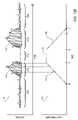
- FIGS. 5A and 5Bdepict two possible optical paths that may be established through a biological member
- FIG. 6Ais a perspective view of the trans-illuminating cuff of FIG. 1A applied to the arm of a neonate;
- FIG. 6Bis a perspective view of the trans-illuminating cuff of FIG. 1A applied to the finger of an adult;
- FIG. 7depicts, from a first perspective, a trans-illuminating patch according to another embodiment of the invention.
- FIG. 8is a view of the trans-illuminating patch of FIG. 7 from a second perspective
- FIG. 9is a front elevational view of the trans-illuminating patch of FIG. 7 applied to the head and neck of an adult;
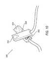
- FIG. 10is a perspective view of a trans-illuminating clip according to another embodiment of the invention.
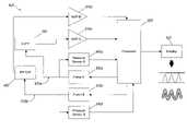
- FIG. 11is a block diagram of a vital sign parameter control system incorporating the trans-illuminating cuff of FIG. 1A and the trans-illuminating patch of FIG. 7 ;
- FIG. 12Aare exemplary pulse waveform signals obtained from the use of the trans-illuminating cuff of FIG. 1A and the trans-illuminating patch of FIG. 7 with a biological member, such as the arm or head of a neonate;
- FIGS. 12B-12Dare exemplary pulse waveform signals of FIG. 12A that have been positioned within an analysis envelope;
- FIGS. 13A and 13Bare further exemplary pulse waveform signals illustrating optical oscillometric blood pressure measurements with a vital sign monitor
- FIG. 14is a graph that illustrates the spectral characteristics of hemoglobin (Hb) and oxygenated hemoglobin (HbO2);
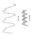
- FIG. 15illustrates the presence of respiratory variations in the graphs of transmittance of light of first and second wavelengths
- FIGS. 16A and 16Bis an exemplary pulse waveform signal that has been labeled to define areas of interest that are related to the pumping action of a heart;
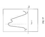
- FIG. 17is an enlarged exemplary pulse waveform signal of FIG. 12A to illustrate transition points of the signal.
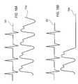
- FIGS. 18A and 18Bare exemplary electrocardiogram signals and an exemplary pulse waveform signals shown for comparison purposes.
- FIG. 1AIllustrated in FIG. 1A is one side of a member trans-illuminating cuff 100 for monitoring certain vital sign parameters of a biological entity.
- a particular biological entity that is discussed in the several embodimentsis a newborn, neonate, or infant (collectively referred to as “neonate” for the remainder of the application and understood to represent not only a person in their early stages of life, but any person of relatively diminutive size, such as an infant, regardless of age).
- neonatea newborn, neonate, or infant
- these several embodiments in use with a neonateit must be understood that these embodiments may also be used to monitor the vital signs of other biological entities such as an adult person or animals (e.g., canines and primates).
- cuff 100includes a flexible support member 122 that can be readily wrapped or applied around an arm, leg, finger or other appendage (collectively referred to as a “limb” for the remainder of the application) of a biological entity.
- limbfor the remainder of the application
- Incorporated within or mounted upon one side of cuff 100is at least one light source 132 and at least one photodetector 134 positioned to diametrically oppose light source 132 when cuff 100 is applied over a limb of a neonate.
- One suitable type of light source for use in cuff 100is a light emitting diode (LED), such as the type L660/805/975-40D00, available from Epitex, Kyoto, Japan, and a suitable photodetector is a photoresistor or photodiode, such as the QSD723 photoresistor available from QT Optoelectronics.
- LEDlight emitting diode
- a suitable photodetectoris a photoresistor or photodiode, such as the QSD723 photoresistor available from QT Optoelectronics.
- other light sources and photodetectors for generating and receiving one of more frequencies of lightmay also be used in cuff 100 without departing from the spirit and scope of the invention.
- cuff 100includes two light sources 132 a and 132 b that are spaced along the interior side of cuff 100 so as to oppose photodetector 134 when cuff 100 is applied over a limb 200 (see, e.g., FIG. 5A ).
- This dual light source configurationprovides for increased transmission of light through the tissue bed and around a bone 210 of limb 200 .
- light source 132 and photodetector 134may be positioned side-by-side to allow for the monitoring of blood parameters based not on light transmitted directly from the light source 132 to the photodetector 134 , but instead on light transmitted into the tissue of the limb 200 by light source 132 and subsequently reflected back to photodetector 134 (see, e.g., FIG. 5B ).
- cuff 100also includes an attachment device 138 for securing cuff 100 to limb 200 of a neonate.
- attachment device 138includes a cinch-loop 140 attached to a first end 142 of the flexible support member 122 through which a second end 144 extends when cuff 100 is applied to the limb of a neonate.
- hook-and-loop style fastener components 146 a and 146 bsuch as Velcro, are applied to the second, or exterior, side of flexible support member 122 .
- fastener components 146 a and 146 bmay be used to secure the cuff 100 in its wrapped position without significantly impeding the flow of blood through the limb (see, e.g., FIGS. 6A and 6B ).
- cuff 100may lack a cinch-loop 140 , relying entirely on hook-and-loop style fastener components 146 a and 146 b to secure cuff 100 .
- further embodimentsmay forgo the hook-and-loop style fastener components 146 a and 146 b in favor of other attachment means, such as, for instance, adhesives, reusable or otherwise, and other types of variable tension fastening systems.
- cuff 100may optionally include one or more inflatable bladders 124 that are either incorporated into cuff 100 or mounted to an interior side of cuff 100 .
- bladder 124may be inflated to a relatively low pressure level that would aid in securing cuff 100 in position while not significantly impeding the flow of blood through limb 200 .
- bladder 124mounts to an interior side of cuff 100 over light source 132 and photodetector 134 .
- bladder 124may be fashioned from a material, such as polyurethane, which is optically transparent to the wavelength of light emitted by light source 132 and to which photodetector 134 is sensitive.
- cuff 100may incorporate a bladder 124 in such a manner that when bladder 124 is inflated, light source 132 and photodetector 134 remain in contact with or proximal to limb 200 . This can be accomplished, for example, by configuring cuff 100 so that light source 132 and photodetector 134 are mounted not upon flexible support member 122 , but upon bladder 124 .
- flexible support member 122may include a generally cylindrical sleeve (not illustrated) that may be slipped around the limb 200 of a neonate.
- the generally cylindrical sleevemay possess elastic characteristics that allow it to stretch and contract as a limb 200 is inserted into the sleeve. The contractile forces generated by the sleeve as it is slipped around a limb 200 also serve to secure the placement of the sleeve without significantly impeding blood flow through the limb.
- flexible support member 122may include a generally cylindrical sleeve that does not have elastic characteristics. Instead, at least one bladder 124 may be incorporated into the sleeve or mounted upon the interior surface of the sleeve. Once sleeve is slipped around the limb 200 of a neonate, bladder 124 may be inflated with sufficient pressure to secure the sleeve around the limb without significantly impeding blood flow. If desired, the bladder may also be inflated to a pressure exceeding the systolic blood pressure of the subject, thereby substantially obstructing the flow of blood through limb 200 .
- a trans-illuminating cuff 300that includes a rigid or semi-rigid housing 310 , such as a plastic tube, into which limb 200 of the neonate can be inserted.
- a rigid or semi-rigid housing 310such as a plastic tube
- at least one light source 332 and at least one photodetector 334are incorporated into or mounted upon housing 310 in such a manner that, upon insertion of limb 200 , light source 332 may transmit light through the tissue of limb 200 , with the transmitted light subsequently being received by photodetector 334 .
- a resilient sleeve or layer of material 320may be incorporated with, or mounted onto, the interior surface of housing 310 .
- Resilient layer 320may include, for example, foam rubber and other materials that readily compress upon being pressed against limb 200 .
- a fixed diameter housing 310may accommodate various limb sizes, the resilient layer 320 compressing and expanding as needed to generally conform to the shape of limb 200 .
- resilient layer 320may be configured so that it does not obstruct the transmission of light from light source 332 into the tissue of limb 200 , nor interfere with the reception of light by photodetector 334 .
- resilient layer 320This can be accomplished through selective placement of resilient layer 320 or, alternatively, by making resilient layer 320 out of a material that is optically transparent to the wavelength(s) of light transmitted by light source 332 and received by photodetector 334 .
- light source 332 and photodetector 334may be positioned on resilient layer 320 instead of housing 310 .
- resilient layer 320aids in positioning the light source 332 and photodetector 334 in close proximity to limb 200 as layer 320 expands and contracts in response to the presence of limb 200 .
- housing 310 of cuff 300may be configured so that resilient layer 320 is supplemented or replaced by at least one bladder (see, e.g., bladder 124 ) that are selectively inflatable to a pressure level sufficient to hold housing 310 in place on limb 200 without significantly impeding the flow of blood through limb 200 .
- the bladder(s)may also be selectively inflated to a pressure exceeding the systolic blood pressure of the neonate, thereby substantially obstructing the flow of blood through limb 200 .
- a trans-illuminating patch 400is provided. Similar to previous embodiments, at least one light source 432 and at least one photodetector 434 are incorporated into or mounted upon patch 400 . Unlike the previous embodiments, patch 400 may be placed on any location or position of the neonate's body and used to monitor the vital sign parameters. Limb 200 may be used for placement, but is not required. Patch 400 may be positioned on the neonate's head, chest, neck, thigh, or other suitable location to monitor vital sign parameters (see e.g., FIG. 9 , patch 400 is positioned on the head and neck of an adult person). Patch 400 may be attached to the particular area of the body with adhesives, reusable or otherwise, or some other attachment device such as a bandage, headband, or the like.
- Patch 400may be positioned on the neonate in relatively flat locations rather than encircling limb 200 like cuffs 100 , 300 . Therefore, light source 432 and photodetector 434 may be positioned side-by-side to allow for monitoring of vital sign parameters based not on light transmitted directly from the light source 432 to photodetector 434 , but instead on light transmitted into the tissue of the neonate's body by light source 432 and subsequently reflected back to photodetector 434 (see, e.g., FIG. 5B ).
- patch 400may also include one or more inflatable bladders (see, e.g., bladder 124 ) that are incorporated into patch 400 .
- the bladdersmay be mounted to patch 400 such that the bladders may be between the neonate and the patch 400 .
- the bladdersmay be fashioned from a material, such as polyurethane, which is optically transparent to the wavelength of light emitted by light sources 432 and to which photodetector 434 is sensitive.
- the bladdersmay be selectively inflated to a pressure exceeding the systolic blood pressure of the neonate, thereby substantially obstructing the flow of blood through that particular area of the neonate's body.
- a trans-illuminating clip 500is provided. Similar to previous embodiments, at least one light source 532 and at least one photodetector 534 are incorporated into or mounted upon clip 500 .
- Clip 500may be secured to smaller portions of the body such as earlobes, fingers, toes, and the like, and used to monitor the vital sign parameters. (see e.g., FIG. 9 , clip 500 is positioned on the earlobe of an adult person).
- Clip 500includes an attachment device 538 that includes a biasing member 540 such as a spring, resilient rubber, or the like, to ensure that light source 532 and photodetector 534 remain proximate the tissue of the neonate.
- control system 600includes a processor 605 that controls, among other things, operation of light sources (e.g., 132 , 432 ) and photodetectors (e.g., 134 , 434 ) in a sensor assembly (e.g. cuff 100 , patch 400 ).
- a sensor assemblye.g. cuff 100 , patch 400 .
- the sensor assembly employing light sources and photodetectorsis the preferred means of generating a signal relating to vital sign parameters, it must be understood that equivalent means for generating signals relating to vital sign parameters may be employed such as ultrasound or the like.
- control system 600is discussed controlling two sensor assemblies, it should be understood that control system 600 may control multiple channels so that multiple sensor assemblies, that are positioned on a neonate, may be used in monitoring vital sign parameters.
- the microprocessorenergizes the light sources continually.
- photodetectorsconvert the light transmitted through the tissue in limb 200 or reflected in head 450 (or other part of the body such as the neck, chest, or thigh) into a corresponding electronic signal.
- This electronic signalis subsequently supplied to processor 605 for analysis after being optionally passed through amplifiers 610 a and 610 b .
- the amplified photodetector output signalis converted to digital form in the microprocessor itself if the microprocessor has an internal A/D converter, or in a separate A/D converter provided between the amplifier and the microprocessor.
- Results of the analysismay then be directed to a variety of output devices, such as, for example, a display screen 620 .
- processor 605is depicted as being separate from the sensor assemblies. However, in an alternative embodiment, control system 600 may be more integrated into the sensor assemblies, with one or more of the components, including processor 605 , being incorporated into the sensor assemblies.
- the sensor assembliesmay also communicate with pumps 630 a , 630 b if one or more inflatable bladders are included in the sensor assemblies. Inflation and deflation of the bladders may be readily controlled by pumps 630 a , 630 b .
- pumps 630 a , 630 bare controlled by processor 605 and convey air into the inflatable bladders through inflation tubes 635 a and 635 b .
- Pressure transducers 640 a and 640 bmay also be incorporated into control system 600 for monitoring the pressure in inflation tubes 635 a and 635 b and the bladders, and conveying signals indicative of such pressure back to the processor 605 . Suitable transducers are available from Cobe Labs, Littleton, Colo.
- a first sensor assemblye.g., cuff 100
- a second sensor assemblye.g., patch 400
- control system 600activates the sensor assemblies by operating or energizing light sources (e.g., 132 , 432 ) and photodetectors (e.g., 134 , 434 ).
- the light sourcesbegin to transmit light of a first wavelength or frequency.
- This transmitted lightrepresenting an optical signal
- This transmitted lightpasses through the skin and into the tissue of limb 200 (see, e.g., FIG. 5A ) and passes through the skin and is reflected off the skull in head 450 (see, e.g., FIG. 5B ).
- the optical signalcontinues to travel through the tissue making up limb 200 and head 450 , including, for example, various types of skin tissue, muscle, and blood vessels.
- portions of the signalare deflected or absorbed.
- the remainder of the optical signal that makes it through the tissue of limb 200is received by the photodetector.
- the remainder of the optical signal that is reflected through the tissue of head 450is received by the photodetector.
- the photodetectorssubsequently convert the optical signals into electric signals to be sent to control system 600 .
- this electric signal produced by the photodetectorsrepresents the transmittance (T) of the optical signal through the tissue of limb 200 and the reflectance (R) through the tissue of head 450 at that moment in time.
- This transmittance (T) or reflectance (R) of the optical signalis not constant, but continuously fluctuates due to ongoing changes occurring in the tissue of limb 200 and head 450 , including without limitation, changes in blood flow.
- bloodis distributed throughout limb 200 and head 450 by a variety of blood vessels, including, for example, arteries and arterioles.
- the rate and volume of blood flow through these vesselsis largely dependent on blood pressure levels, which in turn are dependent on the pumping action of the heart as well as the blood vessels themselves, some of which constrict or dilate depending on the current biological state of the subject. Accordingly, the transmittance (T) of the optical signals through the tissue of limb 200 and reflectance (R) of the optical signals through the tissue of the head 450 are dependent on volumetric changes in blood flow, which, in turn, are dependent on blood pressure levels.
- Pulse waveform signal 700 ais obtained after securing the first sensor assembly around limb 200 and energizing the light source and the photodetector.
- a similar pulse waveform 700 bis obtained after securing the second sensor assembly to head 450 and energizing the light source and the photodetector.
- the rhythmic pattern of fluctuations or oscillations within pulse waveform signals 700 a , 700 brepresent changes in the volumetric flow of blood through limb 200 or head 450 primarily due to the pumping or “beating” action of the human heart.
- pulse waveform signals 700 a , 700 bpermit the determination of certain blood parameters that influence the flow of blood, such as, for example, mean arterial blood pressure, diastolic blood pressure and systolic blood pressure. This determination is possible due to the relationships, as discussed above, between transmittance (T) of the optical signal and between reflectance (R) of the optical signal, volumetric changes in blood flow, and blood pressure levels.
- analysis of pulse waveform signals 700 a , 700 bincludes the application of one or more algorithms that manipulate the data of pulse waveform signals 700 a , 700 b in accordance with one or more predefined relationships that exist between transmittance (T) and reflectance (R) of the optical signal, blood flow and blood pressure levels. This is further discussed below.
- the microprocessormay be suitably programmed to generate an envelope 702 from the pulse waveform signal.
- Envelope 702is comprised of a lower band 704 and upper band 706 that may be positioned around subsequent pulse waveform signals.
- Envelope 702may be used to further aid health care professionals in the near continuous monitoring of a neonate's vital sign parameters and for diagnostic analysis.
- Microprocessor 605may generate envelope 702 from pulse waveform signal 700 a by using a signal sampling technique that is known in the art of signal processing.
- the microprocessormay be programmed to “sample” the pulse waveform signal periodically. Sampling the pulse waveform signal produces a second signal that may be similar to the original pulse waveform signal. The number of samples taken and the time period between samples will determine how closely the sampled signal resembles the original pulse waveform signal taken from the cuff, patch or other like device.
- the microprocessormay be programmed such that lower band 704 and upper band 706 may be developed from the sampled signal, as determined by a healthcare professional, by adjusting the signal gain to produce envelope 702 .
- FIG. 12Billustrates envelope 702 that is a set of simple limit bars (lower band 704 and upper band 706 ) that are based on a sampled electrical signal from the sensor assembly.
- microprocessorsamples the pulse waveform signal at only a few points to identify the peak value of the pulse waveform signal. The microprocessor then sets the lower and upper bands of the envelope based upon the peak value or as directed by a healthcare professional.
- envelope 702more closely resembles the pulse waveform signal that was generated by the microprocessor from the electrical signal received from the sensor assembly.
- the envelope in FIG. 12Cis based on more frequent sampling of the pulse waveform signal than the envelope in FIG. 12B .
- the envelope in FIG. 12Dis based on an even greater frequency of sampling of the pulse waveform signal then the envelope in FIG. 12C so that the lower and upper bands more closely resemble the actual pulse waveform signal.
- the sampling period of the microprocessormay be adjusted to be used in the manner determined by the health care professional.
- the greater the frequency of the sampling periodthe greater the number of sampling points generated, and the more the envelope will resemble the actual electrical signal from the sensor assembly. In this manner the health care professional will have greater precision when employing the use of an envelope in a diagnostic analysis or a near continuous monitor mode.
- envelope 702may be employed for a number of continuous monitoring and diagnostic analysis techniques. For example, an audible alert may be incorporated into control system 600 such that during continuous monitoring of a neonate with sensor assemblies, an alarm may be sounded if the incoming electrical signal crosses either lower band 704 or upper band 706 indicating a unwanted change in vital sign parameters.
- pulse waveform signal 700 amay be analyzed through a process of comparing signal 700 a to a number of previously established pulse waveform signals that have already been associated with one or more known vital sign measurements Specifically, the present analysis method involves the creation of a database of reference envelopes based on previous pulse waveform signals and corresponding blood flow characteristics associated with the reference signals. Each individual envelope characteristic in the database or, alternatively, a combination of two or more envelope characteristics, is then associated with one or more vital sign measurements, such as, for example, blood pressure respiration, and heart rate. A pulse waveform signal 700 a undergoing analysis is evaluated for one or more identifiable and defining characteristics.
- These defining characteristics in the evaluated pulse waveform signal 700 aare compared to the established envelope characteristics maintained in the database. If this comparison meets certain predetermined criteria between the characteristics of the pulse waveform signal 700 a being analyzed and the specific reference characteristics stored in the database, it can be assumed that the blood parameters associated with pulse waveform signal 700 a are the same as the known blood parameters associated with the selected reference envelopes stored in the database. The known blood parameters corresponding to the monitored waveform signal 700 a may then be presented to the healthcare provider, such as on display 620 .
- the envelopes developed from the pulse waveform signalsmay be generated and stored in databases for an entire population.
- a generic database of envelopesmay be developed that may be based on age, gender, size, or any number of attributes. By employing the use of these databases, health care professionals may be able to establish a base line reading for those people who have not had a medical physical in quite some time. Rather than taking several months or years to establish a baseline, a generic pulse waveform envelope baseline can be drawn from the database based on parameters such as size, age, and gender, and the person's pulse waveform signal monitored against established envelopes. While, every person will still require an individual assessment, irregularities may be identified in advance with the use of the generic database of envelopes that closely correspond to a particular person's size, age, gender, etc.
- an individual database of envelopesmay be developed for future diagnostic analysis.
- One examplemay involve a person who visits his health care professional for regular physicals. Each time the person returns his yearly physical, the healthcare professional can access his previous envelopes to be used in comparison purposes with the new pulse waveform signal that is presently being generated. The healthcare professional may be alerted to potential physiological problems if the new signal passes outside the envelope indicating a change in the person's vital sign parameters.
- a personmay find himself in an accident where he is unconscious and cannot communicate with onsite health care professionals.
- Identification information about the victimcan be entered into a computer and the onsite professionals can access the victim's database of pulse waveform signal envelopes to identify any of the victim's vital sign parameter abnormalities that may require attention prior to treating the victim. In this manner, people may receive a relatively quick and accurate diagnosis, which in turn leads to quick and more importantly the correct form of treatment.
- Physiological markers that may be monitored and measured by these embodimentsmay include, but are not limited to, glucose levels, lactate, C-reactive protein, cytokines, white blood cell counts, and gene or protein expression in-vivo. These biological markers not only provide insight into the health status, but also address pre-symptomatic activity due to infection, chemical or biological agent exposure.
- Microprocessor 605may also compare pulse waveform signal 700 a produced from the first sensor assembly positioned around limb 200 (see e.g., FIGS. 6A and 6B ), with pulse waveform signal 700 b produced from the second sensor assembly positioned on head 450 (see e.g., FIG. 9 ).
- a database of envelope signalsmay be created for comparison purposes.
- the health care providermay monitor these waveforms taken from different areas of the subject to diagnosis possible internal biological problems that may be found between the monitoring devices.
- the two separate sensor assembliesmay be used in conjunction with one another for vital sign comparison purposes and analysis of the neonate.
- the sensor assemblymay also be configured to actively measure blood pressure of a subject through an oscillometric-based method.
- the sensor assemblymay include at least one inflatable bladder selectively operable to occlude blood flow in limb 200 or head 450 upon inflation to a sufficiently high enough pressure.
- FIGS. 13A and 13Bdepicts a pulse waveform signal 710 along with a graph 720 of corresponding sensor assembly pressure.
- a pulse waveform signal 710is obtained by applying the sensor assembly around limb 200 or to head 450 of the subject and then subsequently energizing the light source to transmit an optical signal through the tissue of the limb or the head to the photodetector.
- the sensor assemblywill generate a first pulse waveform signal 710 a that is similar in nature to the pulse waveform signals 700 a , 700 b obtained in the previously discussed embodiment of the invention.
- pump 630 a , 630 bactivates, thereby increasing the pressure in the bladders, as illustrated in FIGS. 13A and 13B by graph segment 722 .
- sensor assemblybegins to constrict limb 200 or head 450 . This constriction causes at least a partial pinching of the blood vessels running through the limb or the head, which, in turn, impedes blood flow through the blood vessels.
- the pulses or oscillations in the pulse waveform signal 710 bfirst increase in amplitude, reach a maximum, and then decrease in amplitude.
- the transition period DE in bladder pressureresults in amplified oscillations or spikes in the pulse waveform signal (see, e.g., segment 710 d ).
- the oscillations in the pulse waveform signalreturn to a substantially uniform level.
- the pulse waveform signalexhibits transient increases in the amplitude of the oscillations occurring in the signal (see, e.g., segments 710 b and 710 d ).
- the microprocessoris also sampling the incoming signal so that an envelope 715 may be generated based upon the transient signal.
- the positive peak of the envelopeis at a point where the pulse amplitude reaches a maximum, identified as mean arterial blood pressure (A m ) in FIGS. 13A and 13B .
- the maximum amplitude of the pulseis also a point where the bladder pressure is substantially equal to mean arterial blood pressure.
- waveform signal segments 710 b and 710 dthat correspond to diastolic blood pressure and systolic blood pressure.
- the determination of the oscillation amplitudes at these pointsallows for the determination of diastolic and systolic blood pressure.
- Empirical studiesindicate that these oscillation amplitudes, identified as A d for diastolic pressure and A s for systolic pressure, are related to the oscillation amplitude A m , which corresponds to mean arterial blood pressure.
- diastolic blood pressurecan be identified by first determining the relationship between A d and A m , which is a fixed constant, and then determining oscillation amplitude A m , which is readily identifiable since, by definition, it is the oscillation of maximum amplitude.
- Systolic blood pressurecan be identified in a similar manner.
- a d /A mis a fixed constant value while the relationship of A s /A m may determined by a linear algorithm. Once these points in time are identified, the corresponding cuff pressures that exist at these two times and which correspond, respectively, to diastolic and systolic blood pressures, are readily determined.
- the steady state signal occurring after the deflation of the bladderwill have the characteristics of the calculated blood pressure.
- the steady state signal (e.g. graph segment 710 e ) generated by the sensor assembly after the measurement of mean arterial pressure and deflation of the bladder,may be monitored in a near-continuous manner.
- the steady state signal generated after the deflation of the bladderis a signature of the measured mean arterial pressure and the calculated blood pressure.
- an envelopemay be positioned around waveform signal 710 e and then monitored for one or more predetermined signal characteristics, such as any substantial deviations or fluctuations occurring in the electrical signal that may cross either the lower or upper limit bands of the envelope and indicated an abnormal condition in the neonate.
- Provided pulse waveform signal 710 eremains in a steady state or near steady state condition, it may be assumed that the previously measured blood pressures levels correlating to the waveform signals 710 e have not substantially changed. If at any time the generated signal from the sensor assembly passes outside of the envelope, control system 600 may be programmed to trigger an alarm to notify health care professionals of the irregularity and/or perform a new blood pressure measurement and calculation as described above.
- an actual blood pressure measurement involving inflation of the bladder and subsequent analysis of the pulse waveform signal 710occurs only when changes in the waveform signal 710 e indicate probable changes in blood pressure.
- continuous monitoring of blood pressurecan be maintained without having the intrusive inflating and deflating of the bladder that may disturb the subject.
- the sensor assemblymay also provide near-continuous monitoring of the pulse or heart rate of the subject. This is accomplished in a manner similar to that previously discussed for providing near-continuous monitoring of blood pressures. Specifically, the sensor assembly is applied to a limb of the subject. If the sensor assembly includes one or more bladders, they should be deflated so as to not constrict the limb, and, consequently, impede blood flow. The light source and the photodetector are energized, generating a pulse waveform signal such as that illustrated in FIG. 12 . A similar waveform signal may be generated by a sensor assembly located elsewhere on the subject such as the head.
- the pulse waveform signals 700 a , 700 bare indicative of the volumetric changes occurring in the flow of blood through the limb or head.
- a typical pulse waveform signal 700will be characterized by a rhythmic pattern of fluctuations or oscillations in the signal. These oscillations represent near-continuous changes in the volumetric blood flow due to the pumping or “beating” action of the heart or cardiac muscle. Consequently, heart rate can be monitored by analyzing the waveform signal and determining the number of oscillations that occur within a predetermined period of time.
- HbO2hemoglobin
- Hb+HbO2oxygenated hemoglobin
- control system 600may be configured to function as a pulse oximeter.
- the sensor assemblymay be configured to generate light of two different wavelengths, such as, for example, 650 nanometers (nm) and 805 nm.
- 650 nanometersnm
- 805 nmnm
- hemoglobin (Hb)offers negligible transmission of light having a wavelength of 650 nm
- oxygenated hemoglobinHbO2
- light having a wavelength of 805 nmtransmits equally well though both hemoglobin (Hb) and oxygenated hemoglobin (HbO2).
- the transmission of light at 650 nmindicates a density of oxygenated hemoglobin (HbO2)
- the transmission of light at 805 nmindicates a density of total hemoglobin (Hb+HbO2).
- control unit 600may be configured to alternately energize the two light sources of the sensor assembly in rapid succession, e.g., energizing the light sources at 200 pulses per second. In this manner, high-intensity, short duration pulses of first and second wavelengths of light are alternately transmitted through the tissue of limb 200 or head 450 . After passing through the tissue of limb 200 or reflecting through the tissue of head 450 , the alternating streams of light are received by the photodetectors, which, according to this embodiment, is a broadband photodetector capable of detecting both wavelengths. Alternatively, two separate narrow band photodetectors can be used with the sensor assembly, each photodetector capable of detecting light of one wavelength but not light of the other wavelength.
- the photodetectorsconvert the two alternating optical signals of different wavelengths into an electric signal representing the transmittance of two wavelengths.
- Processor 605analyzes the signal and determines the optical density for each of the two wavelengths.
- the ratio of first wavelength to second wavelength optical densityis subsequently calculated and scaled to provide an output value corresponding to the percentage of oxygen saturation.
- the output value generated from the ratio of optical densitiescan be compared to an appropriate calibration curve programmed into processor 605 , such as, for example, in the form of a lookup table.
- the calibration curverelates optical density to a suspension, such as blood, and is derived from a variation of Beer's law that relates optical density to the concentration of a dissolved substance.
- the senor assemblyincludes at least one inflatable bladder.
- the bladdermay be inflated to a sufficiently high enough pressure so that it constricts the limb or head and drives or squeezes substantially all the blood out of the vessels that run within the portion of the limb or head located in the cuff or beneath the patch. The constriction of the limb or head ensures a lack of blood within the optical path established between the light source and the photodetector. An optical signal passed through these bloodless regions of the limb and head can then be assigned a 100% transmission value.
- the photodetectorscan be synchronously energized with the light sources. This feature ensures that the photodetectors are turned on only when a light source is energized, and minimizes the amount of power drawn by the system, as well as the amount of heat generated by the light sources and photodetectors.
- the present inventionmay also be configured to monitor the respiration rate of a neonate.
- blood oxygen saturation levelsvary subtly with the breathing process, which includes the inspiration of oxygen and expiration of waste gases such as carbon dioxide.
- the sensor assemblypossesses short enough response times in its measuring capabilities to detect the subtle rhythmic changes that occur in blood oxygen saturation levels due to the breathing process.
- FIG. 15depicts an analog recording of the transmittance of the first and second wavelengths of light, such as 650 nm and 805 nm, used to measure blood oxygen saturation levels.
- the relatively high-frequency oscillations 800that occur in the signals due to the pumping of the cardiac or heart muscle, the more subtle rhythmic variations caused by respiration are readily identified within the signals by the addition of a signal envelope 820 .
- the pulse waveform signal generated by sensor assemblymay be analyzed to interpret the performance of the cardio-vascular and pulmonary systems in a human being.
- FIGS. 16A and 16Billustrate a pulse volume waveform signal similar to pulse waveform signal 700 a of FIG. 12A .
- the pulse volume waveform signal of FIG. 16Ahas been labeled as follows to define areas of interest that are related to the pumping action of the heart:
- the pulse waveform signal generated by the sensor assemblymay be used to produce a Myocardial Contractility Index or “Cardiac Index” and a Tissue Perfusion Index.
- Myocardial Contractilityis the ability of the cardiac muscle to contract. The greater the ability of the cardiac muscle to contract, the greater the cardiac output.
- Tissue perfusionis related to the volume and flow of blood through the blood vessels. Tissue perfusion is related to ability of body tissues to efficiently exchange waste and nutrients with the blood and is related to the oxygen saturation levels.
- a cardiac index and a perfusion indexmay be developed from the pulse waveform signals generated by the sensor assembly.
- FIG. 17illustrates a pulse volume waveform signal similar to pulse waveform signal 700 a of FIG. 12A .
- the microprocessormay be suitably programmed to determine the slope of the curve as well as the area under the curve associated with a single contraction or beat of the heart. This single contraction is represented by a time period from t 0 to t total .
- the maximum acceleration, determined by the upward slope of the curverepresents the maximum contractility of the myocardium at a particular heart rate.
- the change in the slopecan be used to develop the Myocardial Contractility Index.
- each of the above ratiosmay change and the rate of change may correlate to underlying heart disease.
- a small change in heart ratemay cause a drastic change in the amount of oxygen being carried in the blood, which changes the efficiency of body tissues to exchange waste and nutrients with the blood.
- a Vascular Elasticity Indexmay also be developed from the same curve used to define the Myocardial Contractility Index and the Tissue Perfusion Index.
- t slope0 - t total t 0 - t total
- Vascular elasticityis a measure of the flexibility of blood vessels. As the flexibility of the blood vessels increase or decrease, each of the above ratios may change and the rate of change may correlate to an underling constriction of the blood vessels leading to heart disease.
- the pulse waveform signal generated from the sensor assemblymay be compared to a signal generated from an electrocardiogram (EKG).
- EKGelectrocardiogram
- a traditional EKGis a measurement of the electrical activity of the heart. There may be cases where an EKG may be reflect the normal electrical activity of the heart, yet there is no actual pumping of blood from the heart. This is known in the art as electromechanical disassociation.
- a sensor assemblysuch as patch 400 or cuff 100 , may be attached to the skin or implanted within the body near or around a major artery such as the aorta. A signal will be generated by the sensor assembly from the flow of blood through the artery as described in previous embodiments. The signal generated by the sensor assembly measures the actual mechanical pumping of the heart as discussed previously.
- FIG. 18Aillustrates the electrical activity of the heart, an EKG 900 , and a signal generated by the pumping action of the heart, the pulse waveform signal similar to 700 a .
- the two signalsmay be monitored concurrently to identify instances when the electrical activity of the heart, as evidenced by the EKG waveform, is present, yet there is no measurement of tissue perfusion by the sensor assembly, i.e., the heart is not pumping (see FIG. 18B ). This would be evidence of electromechanical disassociation. Electromechanical disassociation, if not recognized, may result in death. Also, both signals may be monitored on a particular person that requires the aid of a pacemaker to ensure that the heart is responding to the signals from the pacemaker.
- a health care professionalmay rely on the actual measurements of mean arterial pressure (see FIGS. 13A and 13B ), myocardial contractility (see FIG. 17 ), tissue perfusion (see FIG. 17 ), and vascular elasticity (see FIG. 17 ) as defined and discussed above to perform a diagnostic analysis or diagnosis of a person without having to rely on a calculation of the traditional diastolic and systolic blood pressure numbers.
- the measurements described aboveare all available signals generated from the sensor assemblies that detect the volume and flow of blood through the vessels.
- a health care professionalmay rely on the actual measurements rather than the calculated systolic and diastolic blood pressure numbers to provide a more precise and accurate diagnosis of the pulmonary system of any particular person.
- Databases of envelopesmay also be created as described in previous embodiments based on the above measurements to develop a number diagnostic indexes such as the cardio index, tissue perfusion index, and vascular elasticity index. These databases may be developed either generically across a population of people based on age, gender, size, etc., or specific to one person based on previous physicals and signal monitoring. The above indexes along with a measurement of mean arterial pressure may be used to quickly, precisely, and accurately diagnose a potentially fatal pulmonary issue if left untreated and more importantly undiscovered.
- a sensor assemblysuch as patch 400 or similar device may be adapted for use in an effort monitor the physical health of a person on the battlefield or in flight during a war or fighting situation.
- the embodiments described above to generate pulse waveform signals to monitor vital sign parametersmay be employed to continuously or periodically monitor a person's physical health in battle.
- radio frequency, ultrasonic, or optical based signalsmay be employed to transmit signals between an individual soldier and a central command center monitoring all soldiers.
- Low power devicessuch as patch 400 may be directly interfaced onto the soldier's outer skin or incorporated into their uniforms or gear.
- the sensor assemblies of the present inventionprovides significant advantages over prior art systems and methods by providing the ability to monitor blood parameters, such as blood pressure, heart rate, oxygen saturation and respiration rate, in a near-continuous manner through analysis of a single optical signal. Furthermore, the non-invasive features of the present invention make it an ideal blood parameter monitor for use with neonates. Traditional monitoring devices, such as, for example, ausculatory and prior oscillometric-based methods for monitoring blood pressure, are frequently ineffective with subjects such as neonates due to their relatively small size. In contrast, the sensor assemblies of the present invention are capable of accurately monitoring blood parameters in a relatively small biological entity by transmitting an optical signal through the limb or head of the biological entity. Indeed, the smaller the biological entity, the less tissue the optical signal has to traverse, resulting in a stronger signal that is received by the photodetector and subsequently analyzed to determine vital sign parameters such as, for example, blood pressure.
- the present inventionhas been drawn to a system and method for monitoring certain vital sign parameters of a neonate by directing an optical signal through the tissue of the neonate's limb or forehead. According to the embodiments discussed up until now, this is accomplished through the use of a cuff-based or patch-based structure that wraps around a limb or is position on a head, or, alternatively, into which a limb is inserted, the cuff and patch structure thereby retaining a light source and photodetector in proximity to the limb and head.
- the present inventioncan be implemented in numerous other configurations that would be as equally effective in providing near-continuous monitoring of certain blood parameters of a neonate.
- no such type of cuff structureis utilized.
- the light source and photodetectorare selectively retained in proximity to the limb through the use of some form of clip or clamping structure that does not encircle the entire limb or, alternatively, through the use of a removable adhesive.
Landscapes
- Health & Medical Sciences (AREA)
- Life Sciences & Earth Sciences (AREA)
- Physics & Mathematics (AREA)
- Heart & Thoracic Surgery (AREA)
- Molecular Biology (AREA)
- Veterinary Medicine (AREA)
- Biophysics (AREA)
- Pathology (AREA)
- Engineering & Computer Science (AREA)
- Biomedical Technology (AREA)
- Public Health (AREA)
- Medical Informatics (AREA)
- General Health & Medical Sciences (AREA)
- Surgery (AREA)
- Animal Behavior & Ethology (AREA)
- Cardiology (AREA)
- Physiology (AREA)
- Vascular Medicine (AREA)
- Spectroscopy & Molecular Physics (AREA)
- Optics & Photonics (AREA)
- Measurement Of The Respiration, Hearing Ability, Form, And Blood Characteristics Of Living Organisms (AREA)
- Measuring Pulse, Heart Rate, Blood Pressure Or Blood Flow (AREA)
Abstract
Description
Ad/Am=X, and
As/Am=Y,
where X and Y are constants that are empirically determined based on certain characteristics of the subject, such as shape. Upon determination of oscillation amplitude Amthrough analysis of the pulse waveform signal, one can readily obtain oscillation amplitudes Adand As. The points on the pulse waveform signal that correspond to oscillation amplitudes Adand Asare then identified, by interpolation if necessary. The relationship of Ad/Amis a fixed constant value while the relationship of As/Ammay determined by a linear algorithm. Once these points in time are identified, the corresponding cuff pressures that exist at these two times and which correspond, respectively, to diastolic and systolic blood pressures, are readily determined.
- A. Ventricular Contraction
- B. Ventricular Pressure Rises and Ventricular Volume Increases otherwise known as the QRS Complex
- C. When ventricular pressure exceeds aortic pressure, the aortic valve opens and blood is ejected into the aorta
- D. Isovolumetric Relaxation, muscle relaxes, but maintains volume, and pressure reduces
- E. The rate of volumetric change is shown by the slope of the curve
- F. Dicrotic Notch is observed and is caused by the closure of the aortic valve
- G. T-Wave (EKG) ends, ventricular pressure decreases, and volume increases
- H., I., J. Are the result of Ventricular Systole
- K., L. Relaxation of the Atrial Chamber provides this signal
Changes in A., B., and C. are understood to be related to the capacity of the heart to contract or “pump performance” while changes in E., F., G., and H. are understood to be related to vascular elasticity. The sampling and envelope technique described above in a previous embodiment may be employed to identify changes in the cardio-vascular and pulmonary systems of a particular human being as illustrated inFIG. 16B . The changes in the pulse volume waveform with respect to the envelope may be analyzed and interpreted by a health care professional to predict in advance heart disease and other cardio-vascular events that may be related to a heart attack.
As the heart rate increases or decreases, each of the above ratios may change and the rate of change may correlate to underlying heart disease. A small change in heart rate may cause a drastic change in the amount of oxygen being carried in the blood, which changes the efficiency of body tissues to exchange waste and nutrients with the blood.
Vascular elasticity is a measure of the flexibility of blood vessels. As the flexibility of the blood vessels increase or decrease, each of the above ratios may change and the rate of change may correlate to an underling constriction of the blood vessels leading to heart disease.
Claims (107)
Priority Applications (6)
| Application Number | Priority Date | Filing Date | Title |
|---|---|---|---|
| US10/958,458US7341560B2 (en) | 2004-10-05 | 2004-10-05 | Apparatuses and methods for non-invasively monitoring blood parameters |
| EP05802897AEP1848321A4 (en) | 2004-10-05 | 2005-10-04 | DEVICES AND METHOD FOR NON-INVASIVE MONITORING OF BLOOD PARAMETERS |
| PCT/US2005/035520WO2006041789A2 (en) | 2004-10-05 | 2005-10-04 | Apparatuses and methods for non-invasively monitoring blood parameters |
| US12/025,564US9380951B2 (en) | 2004-10-05 | 2008-02-04 | Non-invasively monitoring blood parameters |
| US12/248,683US20090312613A1 (en) | 2004-10-05 | 2008-10-09 | Non-invasively monitoring blood parameters |
| US15/649,908US20170311824A1 (en) | 2004-10-05 | 2017-07-14 | Non-invasively monitoring blood parameters |
Applications Claiming Priority (1)
| Application Number | Priority Date | Filing Date | Title |
|---|---|---|---|
| US10/958,458US7341560B2 (en) | 2004-10-05 | 2004-10-05 | Apparatuses and methods for non-invasively monitoring blood parameters |
Related Child Applications (1)
| Application Number | Title | Priority Date | Filing Date |
|---|---|---|---|
| US12/025,564ContinuationUS9380951B2 (en) | 2004-10-05 | 2008-02-04 | Non-invasively monitoring blood parameters |
Publications (2)
| Publication Number | Publication Date |
|---|---|
| US20060074283A1 US20060074283A1 (en) | 2006-04-06 |
| US7341560B2true US7341560B2 (en) | 2008-03-11 |
Family
ID=36126449
Family Applications (4)
| Application Number | Title | Priority Date | Filing Date |
|---|---|---|---|
| US10/958,458Expired - LifetimeUS7341560B2 (en) | 2004-10-05 | 2004-10-05 | Apparatuses and methods for non-invasively monitoring blood parameters |
| US12/025,564Active2029-07-06US9380951B2 (en) | 2004-10-05 | 2008-02-04 | Non-invasively monitoring blood parameters |
| US12/248,683AbandonedUS20090312613A1 (en) | 2004-10-05 | 2008-10-09 | Non-invasively monitoring blood parameters |
| US15/649,908AbandonedUS20170311824A1 (en) | 2004-10-05 | 2017-07-14 | Non-invasively monitoring blood parameters |
Family Applications After (3)
| Application Number | Title | Priority Date | Filing Date |
|---|---|---|---|
| US12/025,564Active2029-07-06US9380951B2 (en) | 2004-10-05 | 2008-02-04 | Non-invasively monitoring blood parameters |
| US12/248,683AbandonedUS20090312613A1 (en) | 2004-10-05 | 2008-10-09 | Non-invasively monitoring blood parameters |
| US15/649,908AbandonedUS20170311824A1 (en) | 2004-10-05 | 2017-07-14 | Non-invasively monitoring blood parameters |
Country Status (3)
| Country | Link |
|---|---|
| US (4) | US7341560B2 (en) |
| EP (1) | EP1848321A4 (en) |
| WO (1) | WO2006041789A2 (en) |
Cited By (39)
| Publication number | Priority date | Publication date | Assignee | Title |
|---|---|---|---|---|
| US20070073128A1 (en)* | 2005-09-29 | 2007-03-29 | Carine Hoarau | Medical sensor for reducing motion artifacts and technique for using the same |
| US20070083094A1 (en)* | 2005-10-11 | 2007-04-12 | Colburn Joel C | Medical sensor and technique for using the same |
| US20070203417A1 (en)* | 2005-09-30 | 2007-08-30 | Yoram Wasserman | Signal processing for pulse oximetry |
| US20070260131A1 (en)* | 2006-05-02 | 2007-11-08 | Chin Rodney P | Clip-style medical sensor and technique for using the same |
| US20080075633A1 (en)* | 2006-09-25 | 2008-03-27 | Rafael Ostrowski | Carbon dioxide detector having borosilicate substrate |
| US20080076995A1 (en)* | 2006-09-22 | 2008-03-27 | Nellcor Puritan Bennett Incorporated | Medical sensor for reducing signal artifacts and technique for using the same |
| US20080078394A1 (en)* | 2006-09-25 | 2008-04-03 | Rafael Ostrowski | Carbon dioxide detector having borosilicate substrate |
| US20080081003A1 (en)* | 2006-09-25 | 2008-04-03 | Rafael Ostrowski | Carbon dioxide detector having borosilicate substrate |
| US20080083265A1 (en)* | 2006-09-25 | 2008-04-10 | Rafael Ostrowski | Carbon dioxide detector having borosilicate substrate |
| US20090171226A1 (en)* | 2007-12-31 | 2009-07-02 | Nellcor Puritan Bennett Llc | System and method for evaluating variation in the timing of physiological events |
| US20090177053A1 (en)* | 2007-12-27 | 2009-07-09 | Nellcor Puritan Bennett Llc | Coaxial LED Light Sources |
| US20090324033A1 (en)* | 2008-06-30 | 2009-12-31 | Nellcor Puritan Bennett Ireland | Signal Processing Systems and Methods for Determining Slope Using an Origin Point |
| US20090324034A1 (en)* | 2008-06-30 | 2009-12-31 | Nellcor Puritan Bennett Ireland | Systems and methods for ridge selection in scalograms of signals |
| US20090326871A1 (en)* | 2008-06-30 | 2009-12-31 | Nellcor Puritan Bennett Ireland | Systems and methods for artifact detection in signals |
| US20100014761A1 (en)* | 2008-06-30 | 2010-01-21 | Nellcor Puritan Bennett Llc | Methods And Systems For Discriminating Bands In Scalograms |
| US7676253B2 (en) | 2005-09-29 | 2010-03-09 | Nellcor Puritan Bennett Llc | Medical sensor and technique for using the same |
| US7811276B2 (en) | 2005-11-10 | 2010-10-12 | Nellcor Puritan Bennett Llc | Medical sensor and technique for using the same |
| US20100298721A1 (en)* | 2009-05-22 | 2010-11-25 | Samsung Electronics Co., Ltd. | Apparatus and method for estimating blood pressure by using variable characteristic ratio |
| US20100331709A1 (en)* | 2008-02-08 | 2010-12-30 | Omron Healthcare Co., Ltd. | Detection unit for blood pressure information measurement device and blood pressure information measurement device |
| US7881762B2 (en) | 2005-09-30 | 2011-02-01 | Nellcor Puritan Bennett Llc | Clip-style medical sensor and technique for using the same |
| US20110082357A1 (en)* | 2008-05-28 | 2011-04-07 | Neetour Medical Ltd. | Method and apparatus for co2 evaluation |
| US8145288B2 (en) | 2006-08-22 | 2012-03-27 | Nellcor Puritan Bennett Llc | Medical sensor for reducing signal artifacts and technique for using the same |
| US8175671B2 (en) | 2006-09-22 | 2012-05-08 | Nellcor Puritan Bennett Llc | Medical sensor for reducing signal artifacts and technique for using the same |
| US8190224B2 (en) | 2006-09-22 | 2012-05-29 | Nellcor Puritan Bennett Llc | Medical sensor for reducing signal artifacts and technique for using the same |
| US8219170B2 (en) | 2006-09-20 | 2012-07-10 | Nellcor Puritan Bennett Llc | System and method for practicing spectrophotometry using light emitting nanostructure devices |
| CN102551887A (en)* | 2010-12-09 | 2012-07-11 | 苏州生物医学工程技术研究所 | Graphic intelligent monitoring system for common diseases of neonates |
| US20120277602A1 (en)* | 2011-04-29 | 2012-11-01 | Bbnt Technologies Corp. | Continuous blood pressure monitoring |
| US8721557B2 (en) | 2011-02-18 | 2014-05-13 | Covidien Lp | Pattern of cuff inflation and deflation for non-invasive blood pressure measurement |
| US9044147B2 (en) | 2010-06-17 | 2015-06-02 | Welch Allyn, Inc. | Detection of noise during heart beat variation evaluation |
| US9072433B2 (en) | 2011-02-18 | 2015-07-07 | Covidien Lp | Method and apparatus for noninvasive blood pressure measurement using pulse oximetry |
| US9492095B2 (en) | 2009-12-02 | 2016-11-15 | Neetour Medical Ltd. | Hemodynamics-based monitoring and evaluation of a respiratory condition |
| WO2018069931A1 (en) | 2016-10-12 | 2018-04-19 | Elfi-Tech Ltd. | Method and apparatus for optically measuring blood pressure |
| US11134901B2 (en) | 2016-03-30 | 2021-10-05 | Elfi-Tech Ltd. | Method and apparatus for optically measuring blood pressure |
| US11350837B2 (en) | 2016-03-30 | 2022-06-07 | Elfi-Tech Ltd. | Method and apparatus for optically measuring blood pressure |
| US11426103B2 (en) | 2008-07-03 | 2022-08-30 | Masimo Corporation | Multi-stream data collection system for noninvasive measurement of blood constituents |
| US11638532B2 (en) | 2008-07-03 | 2023-05-02 | Masimo Corporation | User-worn device for noninvasively measuring a physiological parameter of a user |
| US12114974B2 (en) | 2020-01-13 | 2024-10-15 | Masimo Corporation | Wearable device with physiological parameters monitoring |
| US12230393B2 (en) | 2005-03-01 | 2025-02-18 | Willow Laboratories, Inc. | Multiple wavelength sensor emitters |
| US12336796B2 (en) | 2021-07-13 | 2025-06-24 | Masimo Corporation | Wearable device with physiological parameters monitoring |
Families Citing this family (119)
| Publication number | Priority date | Publication date | Assignee | Title |
|---|---|---|---|---|
| ATE479343T1 (en)* | 2002-10-01 | 2010-09-15 | Nellcor Puritan Bennett Inc | USE OF A HEADBAND FOR VOLTAGE DISPLAY AND SYSTEM OF OXYMETER AND HEADBAND |
| US7047056B2 (en) | 2003-06-25 | 2006-05-16 | Nellcor Puritan Bennett Incorporated | Hat-based oximeter sensor |
| US7485094B2 (en)* | 2003-09-30 | 2009-02-03 | Smithmarks, Inc. | Methods of diagnosis using pulse volume measurement |
| US8412297B2 (en)* | 2003-10-01 | 2013-04-02 | Covidien Lp | Forehead sensor placement |
| DE602006010831D1 (en)* | 2005-03-14 | 2010-01-14 | Philips Intellectual Property | METHOD AND DEVICE FOR DETERMINING THE BLOOD IN A BODY ELEMENT |
| US8730031B2 (en) | 2005-04-28 | 2014-05-20 | Proteus Digital Health, Inc. | Communication system using an implantable device |
| EP3827747A1 (en) | 2005-04-28 | 2021-06-02 | Otsuka Pharmaceutical Co., Ltd. | Pharma-informatics system |
| US8802183B2 (en) | 2005-04-28 | 2014-08-12 | Proteus Digital Health, Inc. | Communication system with enhanced partial power source and method of manufacturing same |
| US8836513B2 (en) | 2006-04-28 | 2014-09-16 | Proteus Digital Health, Inc. | Communication system incorporated in an ingestible product |
| US8912908B2 (en) | 2005-04-28 | 2014-12-16 | Proteus Digital Health, Inc. | Communication system with remote activation |
| US9198608B2 (en) | 2005-04-28 | 2015-12-01 | Proteus Digital Health, Inc. | Communication system incorporated in a container |
| US8547248B2 (en) | 2005-09-01 | 2013-10-01 | Proteus Digital Health, Inc. | Implantable zero-wire communications system |
| JP2009544338A (en) | 2006-05-02 | 2009-12-17 | プロテウス バイオメディカル インコーポレイテッド | Treatment regimen customized to the patient |
| US8696593B2 (en)* | 2006-09-27 | 2014-04-15 | Covidien Lp | Method and system for monitoring intracranial pressure |
| EP2073712B1 (en)* | 2006-09-29 | 2010-05-26 | Koninklijke Philips Electronics N.V. | Method and apparatus for hands-free ultrasound |
| JP4552919B2 (en)* | 2006-10-05 | 2010-09-29 | オムロンヘルスケア株式会社 | Sphygmomanometer cuff and sphygmomanometer |
| EP2087589B1 (en) | 2006-10-17 | 2011-11-23 | Proteus Biomedical, Inc. | Low voltage oscillator for medical devices |
| JP4839179B2 (en)* | 2006-10-18 | 2011-12-21 | 敏明 中島 | Treatment system, treatment apparatus, and control method |
| SG175681A1 (en) | 2006-10-25 | 2011-11-28 | Proteus Biomedical Inc | Controlled activation ingestible identifier |
| US8718193B2 (en) | 2006-11-20 | 2014-05-06 | Proteus Digital Health, Inc. | Active signal processing personal health signal receivers |
| CN101686800A (en) | 2007-02-01 | 2010-03-31 | 普罗秋斯生物医学公司 | Ingestible Event Marker System |
| US8956288B2 (en) | 2007-02-14 | 2015-02-17 | Proteus Digital Health, Inc. | In-body power source having high surface area electrode |
| US20080221399A1 (en)* | 2007-03-05 | 2008-09-11 | Triage Wireless, Inc. | Monitor for measuring vital signs and rendering video images |
| EP2063771A1 (en) | 2007-03-09 | 2009-06-03 | Proteus Biomedical, Inc. | In-body device having a deployable antenna |
| EP2124725A1 (en) | 2007-03-09 | 2009-12-02 | Proteus Biomedical, Inc. | In-body device having a multi-directional transmitter |
| US8115618B2 (en) | 2007-05-24 | 2012-02-14 | Proteus Biomedical, Inc. | RFID antenna for in-body device |
| US9186089B2 (en) | 2007-09-14 | 2015-11-17 | Medtronic Monitoring, Inc. | Injectable physiological monitoring system |
| WO2009036327A1 (en) | 2007-09-14 | 2009-03-19 | Corventis, Inc. | Adherent device for respiratory monitoring and sleep disordered breathing |
| US8116841B2 (en) | 2007-09-14 | 2012-02-14 | Corventis, Inc. | Adherent device with multiple physiological sensors |
| WO2009036369A1 (en) | 2007-09-14 | 2009-03-19 | Corventis, Inc. | System and methods for wireless body fluid monitoring |
| EP3922171A1 (en) | 2007-09-14 | 2021-12-15 | Medtronic Monitoring, Inc. | Adherent cardiac monitor with advanced sensing capabilities |
| EP2194858B1 (en) | 2007-09-14 | 2017-11-22 | Corventis, Inc. | Medical device automatic start-up upon contact to patient tissue |
| WO2009036316A1 (en) | 2007-09-14 | 2009-03-19 | Corventis, Inc. | Energy management, tracking and security for adherent patient monitor |
| DK2192946T3 (en) | 2007-09-25 | 2022-11-21 | Otsuka Pharma Co Ltd | In-body device with virtual dipole signal amplification |
| CN104376659B (en) | 2008-03-05 | 2019-10-25 | 普罗透斯数字保健公司 | The ingestible event flag of multi-modal communications and system, and the method using it |
| EP2257216B1 (en) | 2008-03-12 | 2021-04-28 | Medtronic Monitoring, Inc. | Heart failure decompensation prediction based on cardiac rhythm |
| JP5738752B2 (en)* | 2008-04-15 | 2015-06-24 | ノニン・メディカル・インコーポレーテッド | Non-invasive optical sensor |
| WO2009146214A1 (en) | 2008-04-18 | 2009-12-03 | Corventis, Inc. | Method and apparatus to measure bioelectric impedance of patient tissue |
| AU2009268827B2 (en) | 2008-07-08 | 2013-10-24 | Proteus Digital Health, Inc. | Ingestible event marker data framework |
| MY154217A (en) | 2008-08-13 | 2015-05-15 | Proteus Digital Health Inc | Ingestible circuitry |
| US8364220B2 (en) | 2008-09-25 | 2013-01-29 | Covidien Lp | Medical sensor and technique for using the same |
| US8257274B2 (en) | 2008-09-25 | 2012-09-04 | Nellcor Puritan Bennett Llc | Medical sensor and technique for using the same |
| US20100081892A1 (en)* | 2008-09-30 | 2010-04-01 | NelIcor Puritan Bennett Ireland | Systems and Methods for Combined Pulse Oximetry and Blood Pressure Measurement |
| US8036748B2 (en) | 2008-11-13 | 2011-10-11 | Proteus Biomedical, Inc. | Ingestible therapy activator system and method |
| EP2358270A4 (en) | 2008-12-11 | 2014-08-13 | Proteus Digital Health Inc | Evaluation of gastrointestinal function using portable electroviscerography systems and methods of using the same |
| TWI503101B (en) | 2008-12-15 | 2015-10-11 | Proteus Digital Health Inc | Body-associated receiver and method |
| US9659423B2 (en) | 2008-12-15 | 2017-05-23 | Proteus Digital Health, Inc. | Personal authentication apparatus system and method |
| US9439566B2 (en) | 2008-12-15 | 2016-09-13 | Proteus Digital Health, Inc. | Re-wearable wireless device |
| SG172847A1 (en) | 2009-01-06 | 2011-08-29 | Proteus Biomedical Inc | Pharmaceutical dosages delivery system |
| KR20110103446A (en) | 2009-01-06 | 2011-09-20 | 프로테우스 바이오메디컬, 인코포레이티드 | Intake-Related Biofeedback and Individualized Medical Treatment Methods and Systems |
| US11678808B2 (en) | 2009-03-13 | 2023-06-20 | Bluedop Medical, Ltd. | Haemodynamic data estimation apparatus and method of use |
| US8515515B2 (en) | 2009-03-25 | 2013-08-20 | Covidien Lp | Medical sensor with compressible light barrier and technique for using the same |
| WO2010111403A2 (en) | 2009-03-25 | 2010-09-30 | Proteus Biomedical, Inc. | Probablistic pharmacokinetic and pharmacodynamic modeling |
| US8781548B2 (en) | 2009-03-31 | 2014-07-15 | Covidien Lp | Medical sensor with flexible components and technique for using the same |
| WO2010113522A1 (en)* | 2009-04-03 | 2010-10-07 | パナソニック株式会社 | Measurement device, and control method for measurement device |
| EP3906845A1 (en) | 2009-04-28 | 2021-11-10 | Otsuka Pharmaceutical Co., Ltd. | Highly reliable ingestible event markers |
| EP2432458A4 (en) | 2009-05-12 | 2014-02-12 | Proteus Digital Health Inc | Ingestible event markers comprising an ingestible component |
| US8558563B2 (en) | 2009-08-21 | 2013-10-15 | Proteus Digital Health, Inc. | Apparatus and method for measuring biochemical parameters |
| WO2011050283A2 (en) | 2009-10-22 | 2011-04-28 | Corventis, Inc. | Remote detection and monitoring of functional chronotropic incompetence |
| TWI517050B (en) | 2009-11-04 | 2016-01-11 | 普羅托斯數位健康公司 | System for supply chain management |
| UA109424C2 (en) | 2009-12-02 | 2015-08-25 | PHARMACEUTICAL PRODUCT, PHARMACEUTICAL TABLE WITH ELECTRONIC MARKER AND METHOD OF MANUFACTURING PHARMACEUTICAL TABLETS | |
| US9451897B2 (en) | 2009-12-14 | 2016-09-27 | Medtronic Monitoring, Inc. | Body adherent patch with electronics for physiologic monitoring |
| US8688185B2 (en)* | 2009-12-18 | 2014-04-01 | Envitec-Wismar Gmbh | Device for measuring blood, tissue, and skin parameters |
| BR112012019212A2 (en) | 2010-02-01 | 2017-06-13 | Proteus Digital Health Inc | data collection system |
| US8965498B2 (en) | 2010-04-05 | 2015-02-24 | Corventis, Inc. | Method and apparatus for personalized physiologic parameters |
| WO2011127252A2 (en) | 2010-04-07 | 2011-10-13 | Proteus Biomedical, Inc. | Miniature ingestible device |
| TWI557672B (en) | 2010-05-19 | 2016-11-11 | 波提亞斯數位康健公司 | Computer system and computer-implemented method to track medication from manufacturer to a patient, apparatus and method for confirming delivery of medication to a patient, patient interface device |
| US12198790B1 (en) | 2010-10-07 | 2025-01-14 | Masimo Corporation | Physiological monitor sensor systems and methods |
| GB201018413D0 (en) | 2010-11-01 | 2010-12-15 | Univ Cardiff | In-vivo monitoring with microwaves |
| JP2014504902A (en) | 2010-11-22 | 2014-02-27 | プロテウス デジタル ヘルス, インコーポレイテッド | Ingestible device with medicinal product |
| WO2012087634A2 (en)* | 2010-12-23 | 2012-06-28 | Draeger Medical Systems, Inc. | Device and method for combined continuous non-invasive measurement of blood pressure and pulse oximetry (spo2) |
| WO2012125425A2 (en) | 2011-03-11 | 2012-09-20 | Proteus Biomedical, Inc. | Wearable personal body associated device with various physical configurations |
| US9756874B2 (en) | 2011-07-11 | 2017-09-12 | Proteus Digital Health, Inc. | Masticable ingestible product and communication system therefor |
| WO2015112603A1 (en) | 2014-01-21 | 2015-07-30 | Proteus Digital Health, Inc. | Masticable ingestible product and communication system therefor |
| PH12014500174A1 (en) | 2011-07-21 | 2024-02-12 | Proteus Digital Health Inc | Mobile communication device, system, and method |
| WO2013023071A1 (en)* | 2011-08-11 | 2013-02-14 | Reflectance Medical, Inc. | Patient interface for reusable optical sensor |
| US8852095B2 (en)* | 2011-10-27 | 2014-10-07 | Covidien Lp | Headband for use with medical sensor |
| US9235683B2 (en) | 2011-11-09 | 2016-01-12 | Proteus Digital Health, Inc. | Apparatus, system, and method for managing adherence to a regimen |
| EP2874886B1 (en) | 2012-07-23 | 2023-12-20 | Otsuka Pharmaceutical Co., Ltd. | Techniques for manufacturing ingestible event markers comprising an ingestible component |
| US20140073877A1 (en)* | 2012-09-11 | 2014-03-13 | Nellcor Puritan Bennett Llc | Methods and systems for determining physiological information using autocorrelation and an envelope technique |
| US10213114B2 (en) | 2012-10-09 | 2019-02-26 | Koninklijke Philips N.V. | System and method for breathing rate measurements |
| AU2013331417B2 (en) | 2012-10-18 | 2016-06-02 | Proteus Digital Health, Inc. | Apparatus, system, and method to adaptively optimize power dissipation and broadcast power in a power source for a communication device |
| US11149123B2 (en) | 2013-01-29 | 2021-10-19 | Otsuka Pharmaceutical Co., Ltd. | Highly-swellable polymeric films and compositions comprising the same |
| US9662051B2 (en)* | 2013-03-08 | 2017-05-30 | D.E. Hokanson, Inc. | Automated assessment of peripheral vascular condition |
| JP6498177B2 (en) | 2013-03-15 | 2019-04-10 | プロテウス デジタル ヘルス, インコーポレイテッド | Identity authentication system and method |
| WO2014144738A1 (en) | 2013-03-15 | 2014-09-18 | Proteus Digital Health, Inc. | Metal detector apparatus, system, and method |
| EP3005281A4 (en) | 2013-06-04 | 2017-06-28 | Proteus Digital Health, Inc. | System, apparatus and methods for data collection and assessing outcomes |
| US9796576B2 (en) | 2013-08-30 | 2017-10-24 | Proteus Digital Health, Inc. | Container with electronically controlled interlock |
| CA2965941C (en) | 2013-09-20 | 2020-01-28 | Proteus Digital Health, Inc. | Methods, devices and systems for receiving and decoding a signal in the presence of noise using slices and warping |
| WO2015044722A1 (en) | 2013-09-24 | 2015-04-02 | Proteus Digital Health, Inc. | Method and apparatus for use with received electromagnetic signal at a frequency not known exactly in advance |
| US10084880B2 (en) | 2013-11-04 | 2018-09-25 | Proteus Digital Health, Inc. | Social media networking based on physiologic information |
| CN103793593B (en)* | 2013-11-15 | 2018-02-13 | 吴一兵 | One kind obtains brain states objective quantitative and refers to calibration method |
| WO2015127436A2 (en)* | 2014-02-24 | 2015-08-27 | The Trustees Of The University Of Pennsylvania | Pressure modulation, motion detection, individualized geometry, and improved optic-skin coupling to improve long term clinical monitoring with diffuse optics |
| US10758130B2 (en)* | 2014-03-31 | 2020-09-01 | Welch Allyn, Inc. | Single site vitals |
| US9844341B2 (en) | 2014-08-14 | 2017-12-19 | Zoll Medical Corporation | Patient interface for reusable optical sensor |
| US11051543B2 (en) | 2015-07-21 | 2021-07-06 | Otsuka Pharmaceutical Co. Ltd. | Alginate on adhesive bilayer laminate film |
| EP3359040A4 (en)* | 2015-08-05 | 2019-07-17 | X-Cardio Corp. KK | Concave optical sensors |
| US20170049404A1 (en)* | 2015-08-19 | 2017-02-23 | Amiigo, Inc. | Wearable LED Sensor Device Configured to Identify a Wearer's Pulse |
| US11660063B2 (en) | 2015-11-18 | 2023-05-30 | Bluedop Medical, Ltd. | System for determining peripheral artery disease and method of use |
| KR20210018961A (en) | 2016-07-22 | 2021-02-18 | 프로테우스 디지털 헬스, 인코포레이티드 | Electromagnetic sensing and detection of ingestible event markers |
| CN109963499B (en) | 2016-10-26 | 2022-02-25 | 大冢制药株式会社 | Method for manufacturing capsules with ingestible event markers |
| US20190104991A1 (en)* | 2017-10-11 | 2019-04-11 | Edwards Lifesciences Corporation | Self closing finger cuff |
| EP3735181B1 (en) | 2018-01-02 | 2024-05-15 | BlueDop Medical, Ltd. | System for determining peripheral artery disease |
| US12194620B2 (en) | 2018-10-15 | 2025-01-14 | Oliver Crisipin Robotics Limited | Selectively flexible extension tool |
| US11707819B2 (en) | 2018-10-15 | 2023-07-25 | General Electric Company | Selectively flexible extension tool |
| FI128751B (en)* | 2019-01-09 | 2020-11-30 | Turun Yliopisto | An apparatus for measuring functionality of an arterial system |
| US11702955B2 (en) | 2019-01-14 | 2023-07-18 | General Electric Company | Component repair system and method |
| US20210076958A1 (en) | 2019-09-12 | 2021-03-18 | Vivonics, Inc. | System and method for non-invasively measuring blood volume oscillations inside the cranium of a human subject and determining intracranial pressure |
| US12405187B2 (en) | 2019-10-04 | 2025-09-02 | General Electric Company | Insertion apparatus for use with rotary machines |
| US11752622B2 (en) | 2020-01-23 | 2023-09-12 | General Electric Company | Extension tool having a plurality of links |
| US11692650B2 (en) | 2020-01-23 | 2023-07-04 | General Electric Company | Selectively flexible extension tool |
| US11613003B2 (en) | 2020-01-24 | 2023-03-28 | General Electric Company | Line assembly for an extension tool having a plurality of links |
| US11371437B2 (en) | 2020-03-10 | 2022-06-28 | Oliver Crispin Robotics Limited | Insertion tool |
| US12091981B2 (en) | 2020-06-11 | 2024-09-17 | General Electric Company | Insertion tool and method |
| WO2022038364A1 (en)* | 2020-08-21 | 2022-02-24 | Bluedop Medical, Ltd | Continuous blood pressure monitoring |
| US12416800B2 (en) | 2021-01-08 | 2025-09-16 | General Electric Company | Insertion tool |
| US11654547B2 (en) | 2021-03-31 | 2023-05-23 | General Electric Company | Extension tool |
| WO2025034809A1 (en)* | 2023-08-08 | 2025-02-13 | Carnegie Mellon University | Blood pressure estimation using near-infrared spectroscopy |
| US20250255505A1 (en)* | 2024-02-10 | 2025-08-14 | Guy P. Curtis | System and method for using blood flow measurements to monitor health functions |
Citations (6)
| Publication number | Priority date | Publication date | Assignee | Title |
|---|---|---|---|---|
| US5111817A (en)* | 1988-12-29 | 1992-05-12 | Medical Physics, Inc. | Noninvasive system and method for enhanced arterial oxygen saturation determination and arterial blood pressure monitoring |
| US5247931A (en)* | 1991-09-16 | 1993-09-28 | Mine Safety Appliances Company | Diagnostic sensor clasp utilizing a slot, pivot and spring hinge mechanism |
| US5379774A (en)* | 1990-10-23 | 1995-01-10 | Sankyo Company Limited | Measurement of arterial elasticity and the frequency characteristic of the compliance of an artery |
| US5676139A (en)* | 1994-12-14 | 1997-10-14 | Ohmeda Inc. | Spring clip probe housing |
| US6470893B1 (en)* | 2000-05-15 | 2002-10-29 | Peter V. Boesen | Wireless biopotential sensing device and method with capability of short-range radio frequency transmission and reception |
| US20030036690A1 (en)* | 2001-06-20 | 2003-02-20 | Geddes Leslie A. | Body-member-illuminating pressure cuff for use in optical noninvasive measurement of blood parameters |
Family Cites Families (44)
| Publication number | Priority date | Publication date | Assignee | Title |
|---|---|---|---|---|
| AU465302B2 (en)* | 1970-09-18 | 1975-09-25 | Richard Neason Stephens Frederick | Perfusion monitor |
| US5020540A (en)* | 1987-10-09 | 1991-06-04 | Biometrak Corporation | Cardiac biopotential analysis system and method |
| US4949725A (en)* | 1988-07-01 | 1990-08-21 | Bio-Logic Systems Corporation | Apparatus and method for displaying electrical activity generated within a living body |
| WO1992003966A1 (en)* | 1990-08-31 | 1992-03-19 | University Of Utah | Method and apparatus for determining blood pressure |
| US5183051A (en)* | 1991-01-14 | 1993-02-02 | Jonathan Kraidin | Means and apparatus for continuously determining cardiac output in a subject |
| US5181518A (en)* | 1991-02-04 | 1993-01-26 | Mcdonagh Paul F | Method of evaluating cardioprotective agents |
| US5148812A (en)* | 1991-02-20 | 1992-09-22 | Georgetown University | Non-invasive dynamic tracking of cardiac vulnerability by analysis of t-wave alternans |
| JP2979933B2 (en)* | 1993-08-03 | 1999-11-22 | セイコーエプソン株式会社 | Pulse wave analyzer |
| US5533511A (en)* | 1994-01-05 | 1996-07-09 | Vital Insite, Incorporated | Apparatus and method for noninvasive blood pressure measurement |
| US5995857A (en)* | 1996-07-01 | 1999-11-30 | Toomim; I. Hershel | Biofeedback of human central nervous system activity using radiation detection |
| US5836887A (en)* | 1996-09-19 | 1998-11-17 | Colin Corporation | Physical information monitor system having means for determining reference range for abnormality determination, based on moving average of previously obtained values |
| US6018673A (en)* | 1996-10-10 | 2000-01-25 | Nellcor Puritan Bennett Incorporated | Motion compatible sensor for non-invasive optical blood analysis |
| US5868679A (en)* | 1996-11-14 | 1999-02-09 | Colin Corporation | Blood-pressure monitor apparatus |
| WO1999007277A1 (en)* | 1997-08-09 | 1999-02-18 | Roche Diagnostics Gmbh | Analytical device for in vivo analysis in the body of a patient |
| US6050951A (en)* | 1997-11-10 | 2000-04-18 | Critikon Company, L.L.C. | NIBP trigger in response to detected heart rate variability |
| CA2333062A1 (en)* | 1998-06-03 | 1999-12-09 | Mohamed K. Diab | Stereo pulse oximeter |
| DE69800355T2 (en)* | 1998-06-05 | 2001-03-01 | Hewlett-Packard Co., Palo Alto | Pulse rate and heart rate matching detection for pulse oximetry |
| JP2000126142A (en)* | 1998-10-29 | 2000-05-09 | Nippon Colin Co Ltd | Non-regard blood continuous blood pressure estimating device |
| US6684090B2 (en)* | 1999-01-07 | 2004-01-27 | Masimo Corporation | Pulse oximetry data confidence indicator |
| US6298267B1 (en)* | 1999-04-30 | 2001-10-02 | Intermedics Inc. | Method and apparatus for treatment of cardiac electromechanical dissociation |
| US6287252B1 (en)* | 1999-06-30 | 2001-09-11 | Monitrak | Patient monitor |
| US6648820B1 (en)* | 1999-10-27 | 2003-11-18 | Home-Medicine (Usa), Inc. | Medical condition sensing system |
| US6277078B1 (en)* | 1999-11-19 | 2001-08-21 | Remon Medical Technologies, Ltd. | System and method for monitoring a parameter associated with the performance of a heart |
| US6591123B2 (en)* | 2000-08-31 | 2003-07-08 | Mallinckrodt Inc. | Oximeter sensor with digital memory recording sensor data |
| US6606510B2 (en)* | 2000-08-31 | 2003-08-12 | Mallinckrodt Inc. | Oximeter sensor with digital memory encoding patient data |
| US6754516B2 (en)* | 2001-07-19 | 2004-06-22 | Nellcor Puritan Bennett Incorporated | Nuisance alarm reductions in a physiological monitor |
| US7139404B2 (en)* | 2001-08-10 | 2006-11-21 | Hear-Wear Technologies, Llc | BTE/CIC auditory device and modular connector system therefor |
| IL145445A (en)* | 2001-09-13 | 2006-12-31 | Conmed Corp | Signal processing method and device for signal-to-noise improvement |
| US6748254B2 (en)* | 2001-10-12 | 2004-06-08 | Nellcor Puritan Bennett Incorporated | Stacked adhesive optical sensor |
| US6701170B2 (en)* | 2001-11-02 | 2004-03-02 | Nellcor Puritan Bennett Incorporated | Blind source separation of pulse oximetry signals |
| US6776764B2 (en)* | 2002-03-01 | 2004-08-17 | University Of Pittsburgh Of The Commonwealth System Of Higher Education | Use of aortic pulse pressure and flow in bedside hemodynamic management |
| US6850788B2 (en)* | 2002-03-25 | 2005-02-01 | Masimo Corporation | Physiological measurement communications adapter |
| JP2003310579A (en)* | 2002-04-24 | 2003-11-05 | Nippon Colin Co Ltd | Organism monitoring apparatus |
| AUPS214502A0 (en)* | 2002-05-06 | 2002-06-06 | Uscom Pty Ltd | Blood flow oxygen measurement |
| WO2004010844A2 (en)* | 2002-07-26 | 2004-02-05 | Cas Medical Systems, Inc. | Method for spectrophotometric blood oxygenation monitoring |
| US6869402B2 (en)* | 2002-08-27 | 2005-03-22 | Precision Pulsus, Inc. | Method and apparatus for measuring pulsus paradoxus |
| ATE479343T1 (en)* | 2002-10-01 | 2010-09-15 | Nellcor Puritan Bennett Inc | USE OF A HEADBAND FOR VOLTAGE DISPLAY AND SYSTEM OF OXYMETER AND HEADBAND |
| AU2002952144A0 (en)* | 2002-10-17 | 2002-10-31 | Perfusion Diagnostics Pty Ltd | Method and apparatus for measuring tissue perfusion |
| WO2004066814A2 (en)* | 2003-01-24 | 2004-08-12 | Proteus Biomedical Inc. | Method and system for remote hemodynamic monitoring |
| US7330750B2 (en)* | 2003-04-25 | 2008-02-12 | Instrumentarium Corp. | Estimation of cardiac death risk |
| US20040220640A1 (en)* | 2003-04-29 | 2004-11-04 | Medtronic, Inc. | Method and apparatus for determining myocardial electrical resitution and controlling extra systolic stimulation |
| US20040249299A1 (en)* | 2003-06-06 | 2004-12-09 | Cobb Jeffrey Lane | Methods and systems for analysis of physiological signals |
| US20040249302A1 (en)* | 2003-06-09 | 2004-12-09 | Cyberkinetics, Inc. | Methods and systems for processing of brain signals |
| US7381187B2 (en)* | 2003-09-12 | 2008-06-03 | Textronics, Inc. | Blood pressure monitoring system and method of having an extended optical range |
- 2004
- 2004-10-05USUS10/958,458patent/US7341560B2/ennot_activeExpired - Lifetime
- 2005
- 2005-10-04EPEP05802897Apatent/EP1848321A4/ennot_activeWithdrawn
- 2005-10-04WOPCT/US2005/035520patent/WO2006041789A2/enactiveSearch and Examination
- 2008
- 2008-02-04USUS12/025,564patent/US9380951B2/enactiveActive
- 2008-10-09USUS12/248,683patent/US20090312613A1/ennot_activeAbandoned
- 2017
- 2017-07-14USUS15/649,908patent/US20170311824A1/ennot_activeAbandoned
Patent Citations (6)
| Publication number | Priority date | Publication date | Assignee | Title |
|---|---|---|---|---|
| US5111817A (en)* | 1988-12-29 | 1992-05-12 | Medical Physics, Inc. | Noninvasive system and method for enhanced arterial oxygen saturation determination and arterial blood pressure monitoring |
| US5379774A (en)* | 1990-10-23 | 1995-01-10 | Sankyo Company Limited | Measurement of arterial elasticity and the frequency characteristic of the compliance of an artery |
| US5247931A (en)* | 1991-09-16 | 1993-09-28 | Mine Safety Appliances Company | Diagnostic sensor clasp utilizing a slot, pivot and spring hinge mechanism |
| US5676139A (en)* | 1994-12-14 | 1997-10-14 | Ohmeda Inc. | Spring clip probe housing |
| US6470893B1 (en)* | 2000-05-15 | 2002-10-29 | Peter V. Boesen | Wireless biopotential sensing device and method with capability of short-range radio frequency transmission and reception |
| US20030036690A1 (en)* | 2001-06-20 | 2003-02-20 | Geddes Leslie A. | Body-member-illuminating pressure cuff for use in optical noninvasive measurement of blood parameters |
Cited By (76)
| Publication number | Priority date | Publication date | Assignee | Title |
|---|---|---|---|---|
| US12230393B2 (en) | 2005-03-01 | 2025-02-18 | Willow Laboratories, Inc. | Multiple wavelength sensor emitters |
| US7904130B2 (en) | 2005-09-29 | 2011-03-08 | Nellcor Puritan Bennett Llc | Medical sensor and technique for using the same |
| US20070073125A1 (en)* | 2005-09-29 | 2007-03-29 | Carine Hoarau | Medical sensor for reducing motion artifacts and technique for using the same |
| US20070073121A1 (en)* | 2005-09-29 | 2007-03-29 | Carine Hoarau | Medical sensor for reducing motion artifacts and technique for using the same |
| US7676253B2 (en) | 2005-09-29 | 2010-03-09 | Nellcor Puritan Bennett Llc | Medical sensor and technique for using the same |
| US7650177B2 (en) | 2005-09-29 | 2010-01-19 | Nellcor Puritan Bennett Llc | Medical sensor for reducing motion artifacts and technique for using the same |
| US8600469B2 (en) | 2005-09-29 | 2013-12-03 | Covidien Lp | Medical sensor and technique for using the same |
| US20070073128A1 (en)* | 2005-09-29 | 2007-03-29 | Carine Hoarau | Medical sensor for reducing motion artifacts and technique for using the same |
| US8965473B2 (en) | 2005-09-29 | 2015-02-24 | Covidien Lp | Medical sensor for reducing motion artifacts and technique for using the same |
| US8060171B2 (en) | 2005-09-29 | 2011-11-15 | Nellcor Puritan Bennett Llc | Medical sensor for reducing motion artifacts and technique for using the same |
| US7729736B2 (en) | 2005-09-29 | 2010-06-01 | Nellcor Puritan Bennett Llc | Medical sensor and technique for using the same |
| US7881762B2 (en) | 2005-09-30 | 2011-02-01 | Nellcor Puritan Bennett Llc | Clip-style medical sensor and technique for using the same |
| US8005523B2 (en)* | 2005-09-30 | 2011-08-23 | Conmed Corporation | Signal processing for pulse oximetry |
| US20070203417A1 (en)* | 2005-09-30 | 2007-08-30 | Yoram Wasserman | Signal processing for pulse oximetry |
| US20070083094A1 (en)* | 2005-10-11 | 2007-04-12 | Colburn Joel C | Medical sensor and technique for using the same |
| US7811276B2 (en) | 2005-11-10 | 2010-10-12 | Nellcor Puritan Bennett Llc | Medical sensor and technique for using the same |
| US8073518B2 (en) | 2006-05-02 | 2011-12-06 | Nellcor Puritan Bennett Llc | Clip-style medical sensor and technique for using the same |
| US8437826B2 (en) | 2006-05-02 | 2013-05-07 | Covidien Lp | Clip-style medical sensor and technique for using the same |
| US20070260131A1 (en)* | 2006-05-02 | 2007-11-08 | Chin Rodney P | Clip-style medical sensor and technique for using the same |
| US8145288B2 (en) | 2006-08-22 | 2012-03-27 | Nellcor Puritan Bennett Llc | Medical sensor for reducing signal artifacts and technique for using the same |
| US8577436B2 (en) | 2006-08-22 | 2013-11-05 | Covidien Lp | Medical sensor for reducing signal artifacts and technique for using the same |
| US8219170B2 (en) | 2006-09-20 | 2012-07-10 | Nellcor Puritan Bennett Llc | System and method for practicing spectrophotometry using light emitting nanostructure devices |
| US8175671B2 (en) | 2006-09-22 | 2012-05-08 | Nellcor Puritan Bennett Llc | Medical sensor for reducing signal artifacts and technique for using the same |
| US8396527B2 (en) | 2006-09-22 | 2013-03-12 | Covidien Lp | Medical sensor for reducing signal artifacts and technique for using the same |
| US20080076995A1 (en)* | 2006-09-22 | 2008-03-27 | Nellcor Puritan Bennett Incorporated | Medical sensor for reducing signal artifacts and technique for using the same |
| US8195264B2 (en) | 2006-09-22 | 2012-06-05 | Nellcor Puritan Bennett Llc | Medical sensor for reducing signal artifacts and technique for using the same |
| US8190225B2 (en) | 2006-09-22 | 2012-05-29 | Nellcor Puritan Bennett Llc | Medical sensor for reducing signal artifacts and technique for using the same |
| US8190224B2 (en) | 2006-09-22 | 2012-05-29 | Nellcor Puritan Bennett Llc | Medical sensor for reducing signal artifacts and technique for using the same |
| US8420405B2 (en) | 2006-09-25 | 2013-04-16 | Covidien Lp | Carbon dioxide detector having borosilicate substrate |
| US8449834B2 (en) | 2006-09-25 | 2013-05-28 | Covidien Lp | Carbon dioxide detector having borosilicate substrate |
| US20080078394A1 (en)* | 2006-09-25 | 2008-04-03 | Rafael Ostrowski | Carbon dioxide detector having borosilicate substrate |
| US20080081003A1 (en)* | 2006-09-25 | 2008-04-03 | Rafael Ostrowski | Carbon dioxide detector having borosilicate substrate |
| US20080083265A1 (en)* | 2006-09-25 | 2008-04-10 | Rafael Ostrowski | Carbon dioxide detector having borosilicate substrate |
| US8431088B2 (en) | 2006-09-25 | 2013-04-30 | Covidien Lp | Carbon dioxide detector having borosilicate substrate |
| US20080075633A1 (en)* | 2006-09-25 | 2008-03-27 | Rafael Ostrowski | Carbon dioxide detector having borosilicate substrate |
| US8431087B2 (en) | 2006-09-25 | 2013-04-30 | Covidien Lp | Carbon dioxide detector having borosilicate substrate |
| US8577434B2 (en) | 2007-12-27 | 2013-11-05 | Covidien Lp | Coaxial LED light sources |
| US20090177053A1 (en)* | 2007-12-27 | 2009-07-09 | Nellcor Puritan Bennett Llc | Coaxial LED Light Sources |
| US20090171226A1 (en)* | 2007-12-31 | 2009-07-02 | Nellcor Puritan Bennett Llc | System and method for evaluating variation in the timing of physiological events |
| US20100331709A1 (en)* | 2008-02-08 | 2010-12-30 | Omron Healthcare Co., Ltd. | Detection unit for blood pressure information measurement device and blood pressure information measurement device |
| US20110082357A1 (en)* | 2008-05-28 | 2011-04-07 | Neetour Medical Ltd. | Method and apparatus for co2 evaluation |
| US8295567B2 (en) | 2008-06-30 | 2012-10-23 | Nellcor Puritan Bennett Ireland | Systems and methods for ridge selection in scalograms of signals |
| US8827917B2 (en) | 2008-06-30 | 2014-09-09 | Nelleor Puritan Bennett Ireland | Systems and methods for artifact detection in signals |
| US8289501B2 (en) | 2008-06-30 | 2012-10-16 | Nellcor Puritan Bennett Ireland | Methods and systems for discriminating bands in scalograms |
| US20090324033A1 (en)* | 2008-06-30 | 2009-12-31 | Nellcor Puritan Bennett Ireland | Signal Processing Systems and Methods for Determining Slope Using an Origin Point |
| US8077297B2 (en) | 2008-06-30 | 2011-12-13 | Nellcor Puritan Bennett Ireland | Methods and systems for discriminating bands in scalograms |
| US8483459B2 (en) | 2008-06-30 | 2013-07-09 | Nèllcor Puritan Bennett Ireland | Systems and methods for ridge selection in scalograms of signals |
| US9113815B2 (en) | 2008-06-30 | 2015-08-25 | Nellcor Puritan Bennett Ireland | Systems and methods for ridge selection in scalograms of signals |
| US20100014761A1 (en)* | 2008-06-30 | 2010-01-21 | Nellcor Puritan Bennett Llc | Methods And Systems For Discriminating Bands In Scalograms |
| US20090326871A1 (en)* | 2008-06-30 | 2009-12-31 | Nellcor Puritan Bennett Ireland | Systems and methods for artifact detection in signals |
| US20090324034A1 (en)* | 2008-06-30 | 2009-12-31 | Nellcor Puritan Bennett Ireland | Systems and methods for ridge selection in scalograms of signals |
| US12023139B1 (en) | 2008-07-03 | 2024-07-02 | Masimo Corporation | User-worn device for noninvasively measuring a physiological parameter of a user |
| US11751773B2 (en) | 2008-07-03 | 2023-09-12 | Masimo Corporation | Emitter arrangement for physiological measurements |
| US11426103B2 (en) | 2008-07-03 | 2022-08-30 | Masimo Corporation | Multi-stream data collection system for noninvasive measurement of blood constituents |
| US11647914B2 (en) | 2008-07-03 | 2023-05-16 | Masimo Corporation | User-worn device for noninvasively measuring a physiological parameter of a user |
| US11642037B2 (en) | 2008-07-03 | 2023-05-09 | Masimo Corporation | User-worn device for noninvasively measuring a physiological parameter of a user |
| US12036009B1 (en) | 2008-07-03 | 2024-07-16 | Masimo Corporation | User-worn device for noninvasively measuring a physiological parameter of a user |
| US11642036B2 (en) | 2008-07-03 | 2023-05-09 | Masimo Corporation | User-worn device for noninvasively measuring a physiological parameter of a user |
| US11638532B2 (en) | 2008-07-03 | 2023-05-02 | Masimo Corporation | User-worn device for noninvasively measuring a physiological parameter of a user |
| US11484229B2 (en) | 2008-07-03 | 2022-11-01 | Masimo Corporation | User-worn device for noninvasively measuring a physiological parameter of a user |
| US11484230B2 (en) | 2008-07-03 | 2022-11-01 | Masimo Corporation | User-worn device for noninvasively measuring a physiological parameter of a user |
| US9585573B2 (en)* | 2009-05-22 | 2017-03-07 | Samsung Electronics Co., Ltd. | Apparatus and method for estimating blood pressure by using variable characteristic ratio |
| US20100298721A1 (en)* | 2009-05-22 | 2010-11-25 | Samsung Electronics Co., Ltd. | Apparatus and method for estimating blood pressure by using variable characteristic ratio |
| US9492095B2 (en) | 2009-12-02 | 2016-11-15 | Neetour Medical Ltd. | Hemodynamics-based monitoring and evaluation of a respiratory condition |
| US9044147B2 (en) | 2010-06-17 | 2015-06-02 | Welch Allyn, Inc. | Detection of noise during heart beat variation evaluation |
| CN102551887A (en)* | 2010-12-09 | 2012-07-11 | 苏州生物医学工程技术研究所 | Graphic intelligent monitoring system for common diseases of neonates |
| US9072433B2 (en) | 2011-02-18 | 2015-07-07 | Covidien Lp | Method and apparatus for noninvasive blood pressure measurement using pulse oximetry |
| US9700217B2 (en) | 2011-02-18 | 2017-07-11 | Covidien Lp | Method and apparatus for noninvasive blood pressure measurement using pulse oximetry |
| US8721557B2 (en) | 2011-02-18 | 2014-05-13 | Covidien Lp | Pattern of cuff inflation and deflation for non-invasive blood pressure measurement |
| US20120277602A1 (en)* | 2011-04-29 | 2012-11-01 | Bbnt Technologies Corp. | Continuous blood pressure monitoring |
| US8747328B2 (en)* | 2011-04-29 | 2014-06-10 | Raytheon Bbn Technologies Corp. | Continuous blood pressure monitoring |
| US11350837B2 (en) | 2016-03-30 | 2022-06-07 | Elfi-Tech Ltd. | Method and apparatus for optically measuring blood pressure |
| US11134901B2 (en) | 2016-03-30 | 2021-10-05 | Elfi-Tech Ltd. | Method and apparatus for optically measuring blood pressure |
| WO2018069931A1 (en) | 2016-10-12 | 2018-04-19 | Elfi-Tech Ltd. | Method and apparatus for optically measuring blood pressure |
| US12114974B2 (en) | 2020-01-13 | 2024-10-15 | Masimo Corporation | Wearable device with physiological parameters monitoring |
| US12336796B2 (en) | 2021-07-13 | 2025-06-24 | Masimo Corporation | Wearable device with physiological parameters monitoring |
Also Published As
| Publication number | Publication date |
|---|---|
| EP1848321A2 (en) | 2007-10-31 |
| US9380951B2 (en) | 2016-07-05 |
| WO2006041789A3 (en) | 2006-06-01 |
| US20060074283A1 (en) | 2006-04-06 |
| US20170311824A1 (en) | 2017-11-02 |
| US20090312613A1 (en) | 2009-12-17 |
| US20080132769A1 (en) | 2008-06-05 |
| WO2006041789A2 (en) | 2006-04-20 |
| EP1848321A4 (en) | 2011-03-02 |
Similar Documents
| Publication | Publication Date | Title |
|---|---|---|
| US7341560B2 (en) | Apparatuses and methods for non-invasively monitoring blood parameters | |
| US5111817A (en) | Noninvasive system and method for enhanced arterial oxygen saturation determination and arterial blood pressure monitoring | |
| EP3270772B1 (en) | Method and apparatus for measuring blood pressure | |
| US6801798B2 (en) | Body-member-illuminating pressure cuff for use in optical noninvasive measurement of blood parameters | |
| CA2492027C (en) | Body surface probe, apparatus and method for non-invasively detecting medical conditions | |
| US8721557B2 (en) | Pattern of cuff inflation and deflation for non-invasive blood pressure measurement | |
| US9072433B2 (en) | Method and apparatus for noninvasive blood pressure measurement using pulse oximetry | |
| EP0512987A4 (en) | Enhanced arterial oxygen saturation determination and arterial blood pressure monitoring | |
| US12419528B2 (en) | Photoplethysmography-based blood pressure monitoring device | |
| US12036005B2 (en) | Apparatus and methods for measuring blood pressure and other vital signs via a finger | |
| KR20200129811A (en) | Blood Pressure Meter And Method For Measuring Blood Pressure Using The Same | |
| US20170055852A1 (en) | Device and system for determining physiological parameters from the sternum bone | |
| JP2025521184A (en) | Apparatus and method for measuring blood pressure and other vital signs via the finger | |
| US12268481B2 (en) | Photoplethysmography-based blood pressure monitoring device | |
| JPH05503856A (en) | Enhanced arterial oxygen saturation determination method and arterial blood pressure monitoring method | |
| US20230363653A1 (en) | Wearable vital signs monitoring device and method | |
| WO2024238220A1 (en) | Photoplethysmography-based blood pressure monitoring device | |
| Mafi | Blood pressure estimation using oscillometric pulse morphology | |
| JPH0221844A (en) | Hemandynamometer probe and blood pressure measuring device | |
| CA2074956A1 (en) | Enhanced arterial oxygen saturation determination and arterial blood pressure monitoring | |
| AU2002318363A1 (en) | Body-member-illuminating pressure cuff for noninvasive optical measurement |
Legal Events
| Date | Code | Title | Description |
|---|---|---|---|
| AS | Assignment | Owner name:THERON TECHNOLOGIES, LLC, INDIANA Free format text:ASSIGNMENT OF ASSIGNORS INTEREST;ASSIGNORS:HENDERSON, LESLIE G.;BAILEY, THEODORE M. BAILEY;REEL/FRAME:015882/0012 Effective date:20040914 | |
| AS | Assignment | Owner name:OPTICAL VITALS, LLC, INDIANA Free format text:CHANGE OF NAME;ASSIGNOR:THERON TECHNOLOGIES, LLC;REEL/FRAME:017944/0739 Effective date:20050830 | |
| AS | Assignment | Owner name:RADER, FISHMAN & GRAUER PLLC, MICHIGAN Free format text:ASSIGNMENT OF ASSIGNORS INTEREST;ASSIGNOR:OPTICAL VITALS, LLC;REEL/FRAME:020360/0647 Effective date:20071129 | |
| STCF | Information on status: patent grant | Free format text:PATENTED CASE | |
| FEPP | Fee payment procedure | Free format text:PAT HOLDER NO LONGER CLAIMS SMALL ENTITY STATUS, ENTITY STATUS SET TO UNDISCOUNTED (ORIGINAL EVENT CODE: STOL); ENTITY STATUS OF PATENT OWNER: LARGE ENTITY Free format text:PAYOR NUMBER ASSIGNED (ORIGINAL EVENT CODE: ASPN); ENTITY STATUS OF PATENT OWNER: LARGE ENTITY | |
| FPAY | Fee payment | Year of fee payment:4 | |
| AS | Assignment | Owner name:COVIDIEN LP, MASSACHUSETTS Free format text:ASSIGNMENT OF ASSIGNORS INTEREST;ASSIGNOR:RADER, FISHMAN & GRAUER PLLC;REEL/FRAME:031678/0508 Effective date:20130805 | |
| FPAY | Fee payment | Year of fee payment:8 | |
| MAFP | Maintenance fee payment | Free format text:PAYMENT OF MAINTENANCE FEE, 12TH YEAR, LARGE ENTITY (ORIGINAL EVENT CODE: M1553); ENTITY STATUS OF PATENT OWNER: LARGE ENTITY Year of fee payment:12 |