US7341530B2 - Virtual strike zone - Google Patents
Virtual strike zoneDownload PDFInfo
- Publication number
- US7341530B2 US7341530B2US10/331,117US33111702AUS7341530B2US 7341530 B2US7341530 B2US 7341530B2US 33111702 AUS33111702 AUS 33111702AUS 7341530 B2US7341530 B2US 7341530B2
- Authority
- US
- United States
- Prior art keywords
- video
- ball
- camera
- strike zone
- determining
- Prior art date
- Legal status (The legal status is an assumption and is not a legal conclusion. Google has not performed a legal analysis and makes no representation as to the accuracy of the status listed.)
- Expired - Lifetime, expires
Links
Images


Classifications
- A—HUMAN NECESSITIES
- A63—SPORTS; GAMES; AMUSEMENTS
- A63F—CARD, BOARD, OR ROULETTE GAMES; INDOOR GAMES USING SMALL MOVING PLAYING BODIES; VIDEO GAMES; GAMES NOT OTHERWISE PROVIDED FOR
- A63F13/00—Video games, i.e. games using an electronically generated display having two or more dimensions
- A63F13/80—Special adaptations for executing a specific game genre or game mode
- A63F13/812—Ball games, e.g. soccer or baseball
- A63F13/10—
- A—HUMAN NECESSITIES
- A63—SPORTS; GAMES; AMUSEMENTS
- A63B—APPARATUS FOR PHYSICAL TRAINING, GYMNASTICS, SWIMMING, CLIMBING, OR FENCING; BALL GAMES; TRAINING EQUIPMENT
- A63B24/00—Electric or electronic controls for exercising apparatus of preceding groups; Controlling or monitoring of exercises, sportive games, training or athletic performances
- A63B24/0021—Tracking a path or terminating locations
- A—HUMAN NECESSITIES
- A63—SPORTS; GAMES; AMUSEMENTS
- A63F—CARD, BOARD, OR ROULETTE GAMES; INDOOR GAMES USING SMALL MOVING PLAYING BODIES; VIDEO GAMES; GAMES NOT OTHERWISE PROVIDED FOR
- A63F13/00—Video games, i.e. games using an electronically generated display having two or more dimensions
- A63F13/20—Input arrangements for video game devices
- A63F13/21—Input arrangements for video game devices characterised by their sensors, purposes or types
- A63F13/213—Input arrangements for video game devices characterised by their sensors, purposes or types comprising photodetecting means, e.g. cameras, photodiodes or infrared cells
- A—HUMAN NECESSITIES
- A63—SPORTS; GAMES; AMUSEMENTS
- A63F—CARD, BOARD, OR ROULETTE GAMES; INDOOR GAMES USING SMALL MOVING PLAYING BODIES; VIDEO GAMES; GAMES NOT OTHERWISE PROVIDED FOR
- A63F13/00—Video games, i.e. games using an electronically generated display having two or more dimensions
- A63F13/45—Controlling the progress of the video game
- A—HUMAN NECESSITIES
- A63—SPORTS; GAMES; AMUSEMENTS
- A63F—CARD, BOARD, OR ROULETTE GAMES; INDOOR GAMES USING SMALL MOVING PLAYING BODIES; VIDEO GAMES; GAMES NOT OTHERWISE PROVIDED FOR
- A63F13/00—Video games, i.e. games using an electronically generated display having two or more dimensions
- A63F13/50—Controlling the output signals based on the game progress
- A63F13/53—Controlling the output signals based on the game progress involving additional visual information provided to the game scene, e.g. by overlay to simulate a head-up display [HUD] or displaying a laser sight in a shooting game
- A—HUMAN NECESSITIES
- A63—SPORTS; GAMES; AMUSEMENTS
- A63F—CARD, BOARD, OR ROULETTE GAMES; INDOOR GAMES USING SMALL MOVING PLAYING BODIES; VIDEO GAMES; GAMES NOT OTHERWISE PROVIDED FOR
- A63F2300/00—Features of games using an electronically generated display having two or more dimensions, e.g. on a television screen, showing representations related to the game
- A63F2300/60—Methods for processing data by generating or executing the game program
- A63F2300/66—Methods for processing data by generating or executing the game program for rendering three dimensional images
- A—HUMAN NECESSITIES
- A63—SPORTS; GAMES; AMUSEMENTS
- A63F—CARD, BOARD, OR ROULETTE GAMES; INDOOR GAMES USING SMALL MOVING PLAYING BODIES; VIDEO GAMES; GAMES NOT OTHERWISE PROVIDED FOR
- A63F2300/00—Features of games using an electronically generated display having two or more dimensions, e.g. on a television screen, showing representations related to the game
- A63F2300/60—Methods for processing data by generating or executing the game program
- A63F2300/69—Involving elements of the real world in the game world, e.g. measurement in live races, real video
- A—HUMAN NECESSITIES
- A63—SPORTS; GAMES; AMUSEMENTS
- A63F—CARD, BOARD, OR ROULETTE GAMES; INDOOR GAMES USING SMALL MOVING PLAYING BODIES; VIDEO GAMES; GAMES NOT OTHERWISE PROVIDED FOR
- A63F2300/00—Features of games using an electronically generated display having two or more dimensions, e.g. on a television screen, showing representations related to the game
- A63F2300/80—Features of games using an electronically generated display having two or more dimensions, e.g. on a television screen, showing representations related to the game specially adapted for executing a specific type of game
- A63F2300/8011—Ball
Definitions
- the present inventionis directed to the depiction of a strike zone (or other) to an image.
- the present inventionpertains to a system that adds a graphical image of the strike zone to a video or other image of a baseball game.
- the systemdetermines location of the strike zone and the ball in real space. The locations of the strike zone and the ball are depicted in the video. Based on knowing the locations of the strike zone and the ball, the system can determines whether the pitch was a strike or a ball.
- the present inventioncan be accomplished using hardware, software, or a combination of both hardware and software.
- the software used for the present inventionis stored on one or more processor readable storage media including hard disk drives, CD-ROMs, DVDs, optical disks, floppy disks, tape drives, RAM, ROM or other suitable storage devices.
- processor readable storage mediaincluding hard disk drives, CD-ROMs, DVDs, optical disks, floppy disks, tape drives, RAM, ROM or other suitable storage devices.
- some or all of the softwarecan be replaced by dedicated hardware including custom integrated circuits, gate arrays, FPGAs, PLDs, and special purpose computers.
- FIG. 1illustrates the graphic effect added by one embodiment of the present invention.
- FIG. 2is a block diagram of the components of one embodiment of the tracking system.
- FIG. 3is a flowchart describing one embodiment of the process for setting the boundaries of the strike zone.
- FIG. 4is a flow chart that explains one embodiment of the process of tracking a baseball.
- FIG. 5is a block diagram of one embodiment of the equipment for the low first and low third cameras.
- FIG. 6is a block diagram of one embodiment of the components at the production center.
- FIG. 7depicts a flowchart which describes one embodiment of the process performed by the enhancement system of FIG. 6 .
- FIG. 8is a flow chart describing one embodiment of the process of determining the offsets based on the edges.
- FIG. 9is a flow chart describing one embodiment of the process of finding a match for one edge that was transformed to the corresponding actual edge in the current field of video.
- One embodiment of the systemadds a graphical image of the strike zone to a video of a baseball game.
- the systemcan be used with live video, still images or replays.
- the virtual strike zone graphicappears as a three dimensional box.
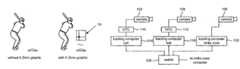
- FIG. 1illustrates the graphic effect added by one embodiment of the present invention.
- the left imageshows a batter at home plate.
- the image on the rightshows a batter at home plate with the strike zone graphic 10 added by the system.
- the graphicwill include cross hairs and a solid circle to indicate the location where the baseball intersected the front plane of the strike zone.
- the three dimensional strike zonewill be seen from different perspectives. The system, however, takes no measures to account for occlusions.
- One embodiment of the present inventionincludes two subsystems: a tracking system and an enhancement system.
- the tracking systemis used to track the three dimensional positions of the ball and the strike zone.
- the enhancement systemis used to add the desired graphical effect to the video of the baseball game.
- FIG. 2is a block diagram of the components of the tracking system.
- the tracking systemincludes two sensor cameras 102 and 104 for tracking a baseball and one sensor camera 106 for tracking the height of the strike zone. These cameras are rigidly mounted and, thus, cannot pan, tilt or zoom.
- the first sensor camera 102is mounted in the stadium, above the field, and approximately perpendicular to the line of the pitch (“first base sensor”).
- the first base sensorhas a field of view that includes the last half of the pitch.
- the second sensor camera 104is near and behind home plate (“high home sensor”).
- the third sensor camera 106used for tracking the height of the strike zone, is positioned to have a good view of home plate. Usually, this camera sensor will be located in center field (“centerfield sensor”).
- the sensor camerasdo not provide video for broadcast, they are only used for tracking the strike zone and the ball.
- the sensor cameras for tracking the ballcommunicate video to Vertical Interval Time Code (VITC) inserters 110 and 112 .
- VTCVertical Interval Time Code
- the video from each VITC inserteris sent to a respective tracking computer 114 and 116 .
- the tracking computers 114 and 116are connected to each other and to the Strike Zone computer 122 (described below) via a switch 126 (using Ethernet).
- the tracking computer connected to the camera sensor for tracking the strike zonehas a graphical user interface (GUI) which is used to set the height of the strike zone.
- GUIgraphical user interface
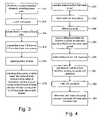
- FIG. 3is a flowchart describing the process for setting the boundaries of the strike zone.
- the physical dimensions of the baseball diamondincluding home plate
- a three dimensional coordinate systemis defined with the origin of the coordinate system at the corner of home plate. This three dimensional coordinate system is used for tracking the baseball, the strike zone and various edges (discussed below). The measurements for the diamond are made in this coordinate system.
- the systemcreates three parallel lines in the three dimensional coordinate system (step 206 ). Each of the three lines is at a different height.
- the three dimensional coordinates of the three linesare converted to two dimensional positions in the video from the center field sensor using a transformation matrix (see step 204 ) based on the orientation and location of the center field sensor (step 208 ).
- the converted linesare then projected on the video from the center field sensor.
- Sliders on a GUI from the tracking computercan be moved to adjust the positions of the lines (step 210 ). There is one slider for each line. The Operator moves the sliders so that the bottom line is at the bottom of the batter's feet, the middle line passes through the hollow of the back of the batter's knee and the top line passes through the batter's belt buckle.
- the operatorcan move the three sliders.
- An operatorcan also move a joystick.
- This joystickwill adjust the top line, the belt buckle line.
- the knee linealso moves to maintain the ratio of spacing between the lines.
- the operatoruses the joy stick.
- the systemcan also operate with separate joysticks for the belt and knee line.
- the tracking computerchanges the three dimensional location of the appropriate line(s). Once a three dimensional position of a line is changed, the new three dimensional position is transformed to a new two dimensional position in the video and the line is moved in the video accordingly.
- the systemcalculates the dimensions of the strike zone as follows (step 212 ).
- the four sides of the three dimensional box representing the strike zoneare defined by the dimensions of home plate.
- the bottom of the strike zoneis set to at the back of the hollow of the batter's knee. This corresponds to the middle line of the three lines.
- the top of the strike zonecorresponds to a position 21 ⁇ 2 diameters of a baseball above the batter's belt buckle (the top line).
- FIG. 4is a flow chart that explains the process of tracking a baseball.
- the operator of the GUI for the master tracking computerwill push a button on the GUI or keyboard to indicate that the batter is set (step 250 ).
- a batteris set when the batter's front foot is planted.
- the set buttonindicates to the system to stop accepting data about the height of the strike zone. It is also used as a trigger the system to save the last second of video and the next second of video to the hard disk (step 252 ).
- step 254the fields of stored video are then differenced against adjoining-in-time fields (even fields are differenced against previous even fields and odd fields are differenced against previous odd fields).
- Each tracking computerlooks at the differenced fields from its associated sensor camera (step 256 ). Prior to the game, an operator will indicate where in the video the ball is expected to be during a pitch. The tracking computer will look in those areas for a cluster of pixels that are in the YUV color space of the ball's color. Pre-set variables define the minimum and maximum sizes of a cluster in numbers of pixels, as well as acceptable shapes for the cluster's bounding box. A number of clusters are thus identified in each field. After a few consecutive fields are processed, the system selects at most one cluster based on relative position: the cluster must be identifiable in subsequent fields, with different positions obtained by a regular translation. The translation parameters (direction, amplitude) are pre-set variables. All such variables can be interactively modified during the operation of the system.
- clusterswere selected for each of the cameras, they are matched (step 258 ). For each pair of matched clusters, a three dimensional position is determined by creating symbolic lines of position from each camera to the potential ball location based on the cluster (step 260 ). An adjoining line is determined at the closest point of intersection between the two lines of position. The three dimensional position determined is based on the x coordinate of the position where the determined adjoining line crosses the line of position from the high home sensor. The y and z coordinates are based on the y and z coordinates of the position where the determined adjoining line crosses the line of position from the first base sensor. The resulting set of three dimensional locations are operated on by a Kalman filter, which filters the data and creates a set of three dimensional locations representing the path of the ball (step 262 ).
- the systemdetermines when and where the ball intersected (or would have intersected) the plane at the front surface of the strike zone (step 264 ).
- the tracking computerreports to the Strike Zone computer a time code indicating when the ball crossed the plane, the three dimensional location where it crossed the plane, whether it was a strike or a ball, and a three dimensional location for where the ball would have hit the catcher's glove.
- the height information for the strike zoneis also communicated at various times during the game.
- the three dimensional location for where the ball would have hit the catcher's gloveis estimated by determining the trajectory of the ball and predicting where it will be one frame after it crosses the front surface of the strike zone.
- the enhancement subsystem of the systemincludes four broadcast cameras, associated hardware, and a production center.
- the four broadcast camerasare located at a high location on the stadium behind home plate (high high home), a low position near the first baseline (low first), a low position near the third baseline (low third) and in center field (center field). The positions vary based on the production requirements and/or the stadium.
- the high high home camera and the center field camerado not pan, tilt or zoom.
- the low first and low third camerascan pan, tilt and zoom.
- FIG. 5is a block diagram of the equipment for the low first and low third cameras.
- the low first and low third cameras 302are each associated with a set of camera sensors (CS) 304 .
- These camera sensorsinclude an optical shaft encoder to measure pan, an optical shaft encoder to measure tilt, a set of inclinometers that measure attitude of the camera head and electronics for sensing the positions of the camera's zoom lens and 2 ⁇ extender.
- the information from the camera sensorsis encoded on an audio signal and sent down one of the microphone channels from the camera to a camera control unit (CCU) 306 .
- the CCUtransmits the video to a VITC inserter 308 which adds time code.
- the output of the VITC inserter 308is sent to a production truck and to one of the edge tracking computers (discussed below).
- the audio signal from CCU 306is sent to an audio demodulator (below).
- FIG. 6is a block diagram of the components at the production center, which is housed in a truck at the stadium.
- the audio signals from the appropriate camerasare received by an audio demodulator 320 which extracts the camera sensor data and provides that camera sensor data to a personal computer, labeled as Gather.
- the camera sensor datais packaged and forwarded to an O2 computer (from Silicon Graphics), labeled as the Strike Zone computer.
- the video that the broadcaster chooses to enhanceis first sent to a VITC inserter 330 , which is synced with the other VITC inserters mentioned above.
- the VITC inserters associated with the broadcast camerasadd a camera ID and a time stamp to lines 21 and 22 of the vertical blanking interval.
- VITC inserter 330adds a time stamp to lines 16 - 18 .
- the video from the VITC inserter 330is sent to the Strike Zone computer and video delay 332 .
- Time code datais sent from the VITC to the Gather computer via an RS232 line.
- Video from the video delayis transmitted to keyer 334 and the Render computer.
- the Strike Zone computerreceives the camera sensor data from the Gather computer, receives the video from VITC inserter 330 , and receives the ball positions and strike zone positions from the master tracking computer.
- the Strike Zone computerdetermines if and where to add the graphics to the video. This information is sent to the Render computer, which renders the graphical enhancement and sends that information to keyer 34 .
- Keyer 34adds the virtual strike zone, cross hairs and solid circle graphics from the Redner computer to the delayed video. From keyer 34 , the video is communicated back to the broadcaster.
- FIG. 7depicts a flowchart which describes the process performed by the enhancement system of FIG. 6 .
- the Strike Zone computerreceives video from the broadcaster (step 400 ). That video includes a camera identifier in the vertical blanking interval. Based on that camera identifier, the Strike Zone computer accesses the appropriate camera sensor data (step 402 ) and transforms the locations of the strike zone (step 404 ) and ball (step 406 ) (if the ball is to be depicted in the video) to two dimensional positions in the video. The Strike Zone computer uses a transformation matrix based on the camera sensor data to perform the transformation. The positions of the strike zone and the ball are then adjusted based on offsets (step 408 ).
- offsetsinclude an X offset and a Y offset, which are in units of pixels. If the X offset is three pixels, then each of the positions determined for the strike zone and the ball are shifted in the X direction by three pixels. The offsets are a measure of the error in the camera sensor data. The determination of the offsets will be discussed below.
- the virtual images of the strike zone, ball position and/or crosshairsare rendered by the Render computer. These images are then added to the video using the keyer (step 410 ).
- the strike zoneis added to every field of video that passes through the keyer.
- the crosshairsare not always added to the video.
- a seven frame animationis created.
- the cross hairsare added with the center of the cross hairs being at the center of the strike zone.
- the cross hairsare centered at the position that the ball intersects the front surface of the strike zone.
- the intervening framesshow the center of the cross hairs at intervening locations moving from the center of the strike zone to the position of the ball when it intersects the strike zone. Note that the seventh frame depicts the game at the time the ball intersects the front surface of the strike zone.
- the pitchwas a ball
- the cross hairsare not added to the video. Instead, a circle is added to the video, indicating the position of the ball when it intersected the plane corresponding to the front surface of the strike zone. If a ball trail is used (if the camera angle is a side view and the pitch was a strike) then a trail animates from the front plane of the strike zone to the estimated position of the ball where it contacted the catcher's glove. This ball trail graphic does not use data from any positions prior to the ball intersecting the strike zone.
- the transformed positions of the ball and strike zoneare adjusted based on an X offset and a Y offset.
- These offsetsare determined by the four edge track computers depicted in FIG. F.
- Each edge track computerreceives camera sensor data from the Gather computer and video for its associated broadcast camera.
- the edge track computerdetermines an X offset and a Y offset for the associated broadcast camera based on edges in the video. These offsets are reported to the Gather computer.
- the Gather computertransmits the offsets to the Strike Zone computer, which uses the appropriate offsets based on which camera supplied the video chosen by the broadcaster.
- edgesPrior to the game, the operator of the system selects a set of edges for use by the edge computers. These edges are frequently updated during the game. The edges selected should be easy to see, and not at the location of or near the perimeter of where the strike zone will be inserted. Each selection of an edge identifies one pixel as the edge.
- An edgeis a color transition in the video image. When an edge is selected, the operator indicates whether the edge is a horizontal edge or a vertical edge. An edge is a horizontal edge if the transition is made between consecutive pixels in a vertical direction, thus (possibly) creating a horizontal line. An edge is a vertical edge if the transition is made between consecutive pixels in a horizontal direction, thus (possibly) creating a vertical line.
- edges and five horizontal edgesare selected, but more is better (e.g. twenty five vertical edges and twenty five horizontal edges).
- the edgesare selected using a mouse.
- the position of the edge pixelsare transformed to locations in three dimensional space.
- the systemstores the color values (e.g. Y, Cr, Cb) for the edge pixel, for seven pixels to one side of the edge pixel, and for eight pixels to the other side of the edge pixel.
- the sixteen consecutive pixelsare on a vertical line.
- For a vertical edgethe sixteen consecutive pixels are on a horizontal line.
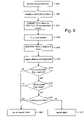
- FIG. 8is a flow chart describing the process of determining the offsets based on the edges.
- step 500 of FIG. 8the three dimensional position of the edge points are transformed to the current field of the video from the broadcaster.
- the appropriate edge tracking computerattempts to match the transformed edges with the same edges in the current field (step 502 ).
- the camera sensor datais error free
- camera lens modelis error free
- the camera platformis perfectly rigid
- the transformed edge positionsmatch the actual positions of the edges in the current field.
- the transformed edge positionsmay differ from the actual positions of the edges in the current field by a small number of pixels.
- the offset processattempts to determine the amount these positions differ.
- the systemdetermines a first average delta X and a first average delta Y (step 504 ).
- the average delta Xis the average difference between the transformed X positions and the actual X positions.
- the average delta Yis the average difference between the transformed Y positions and the actual Y positions.
- each of the transformed edge positionsare updated by the average delta X and average delta Y values (step 506 ).
- the systemattempts to match the transformed edges having positions updated by the average delta X and average delta Y values with the actual edges in the current field (step 508 ).
- a new set of average delta X and an average delta Y valuesare computed (step 510 ).
- “Outlier” edgesare then removed (step 512 ).
- An “outlier” edgeis an edge having an associated delta X that is more than three pixels different than the latest average delta X or an edge having an associated delta Y that is more than three pixels different than the latest average delta Y.
- average delta X and average delta Yare recalculated (step 514 ).
- the systemdetermines whether there is enough data being used to calculate the average delta X and the average delta Y (step 516 ). In the current implementation, there is enough data if the average delta X is based on five or more edge matches and the average delta Y is based on five or more edge matches. If there is not enough data, then the offsets (one or both) are not reported by the process of FIG. 8 (step 518 ). The rejection of the X offset due to insufficient data is independent from the rejection of the Y offset due to insufficient data. If there is sufficient data, then the latest average delta X is reported as the X offset and/or the latest average delta Y is reported as the Y offset (step 520 ).
- FIG. 9is a flow chart describing the process of finding a match for one edge that was transformed to the corresponding actual edge in the current field of video.
- the process of FIG. 9is performed for each transformed edge prior to determining average delta X and delta Y.
- the systemstarts by finding the closest scan line to the transformed edge (step 600 ).
- Each edgehad a three dimensional position that is transformed into X and Y coordinates on the current field.
- the Y coordinaterepresents a scan line in the video field.
- the Y coordinatemay not necessarily be an integer. Therefore, the transformed Y coordinate is rounded to the nearest integer in order to identify the closest scan line.
- the systemalso identifies the closest pixel position (step 602 ). That is, the transformed X coordinate pertains to a pixel position on a scan line. If the transformed X coordinate is not an integer, it is rounded to the nearest integer in order to identify a pixel.
- the color value for the edge pixel and the fifteen pixels on the two sides of the edge pixelare compared to the color values of sixteen consecutive pixels in the field. This comparison is performed forty one times.
- the first comparisonis made by lining up the edge pixel with the pixel in the current field having the same pixel position and scan line as previously determined.
- the other fifteen pixels for the edgeare compared against corresponding pixels in the current field.
- the center pixelmay have coordinates ( 50 , 100 ), and the other fifteen pixels may have coordinates of ( 42 , 100 ), ( 43 , 100 ), ( 44 , 100 ), ( 45 , 100 ), ( 46 , 100 ), ( 47 , 100 ), ( 48 , 100 ), ( 49 , 100 ), ( 51 , 100 ), ( 52 , 100 ), ( 53 , 100 ), ( 54 , 100 ), ( 55 , 100 ), ( 56 , 100 ), and ( 57 , 100 ).
- These sixteen edge pixelsare compared to the sixteen pixels in the current field having the same coordinates.
- the comparisonincludes determining the difference between the Y values, Cr values or Cb values.
- the comparisondetermines forty eight difference values, which are then added together to determine a score for the entire comparison.
- This comparison process(step 604 ) is done forty more times, generating forty more scores. However, for each additional comparison the sixteen edge pixels are compared against a different set of pixels from the current field by offsetting the coordinates by up to +/ ⁇ 20. If the edge is a horizontal edge, then the X coordinate is changed for each pixel at each comparison. For example, the center edge having coordinates ( 50 , 100 ) will first be compared against the pixel from the current field having coordinates of ( 50 , 100 ). Subsequent comparison for that edge pixel will look at pixels in the current field with coordinates of ( 30 , 100 ), ( 31 , 100 ), ( 32 , 100 ), . . .
- each scoreassociated with an offset up to +/ ⁇ 20.
- the above exampleis explained in regard to a horizontal edge.
- a vertical edgea vertical set of pixels is compared to sets of vertical pixels with the scan line being changed +/ ⁇ 20 scan lines.
- the scoresare plotted on a graph with score as the vertical axis and offset as the horizontal axis.
- a parabolais fitted to the data (step 606 ).
- the systemdetermines the offset value at the bottom of the parabola (step 608 ) and rounds that offset value to the nearest integer (step 610 ).
- the three diamonds depicted in the flow chart of FIG. 9include three tests for determining whether the rounded offset is reliable data.
- the systemdetermines whether the lowest score of all forty one scores is lower than a threshold (e.g. 500). If not, the rounded offset is not reported (step 620 ).
- step 614the system determines whether the best score divided by the average score is lower than a test factor (e.g. 0.5). If not, the rounded offset is not reported (step 620 ). Third, in step 616 , the system determines whether there is another low offset. That is, is there another valley in the data/curve. If so, the rounded offset is not reported (step 620 ). Otherwise, the rounded offset is reported (step 622 ).
- a test factore.g. 0.5
Landscapes
- Engineering & Computer Science (AREA)
- Multimedia (AREA)
- Human Computer Interaction (AREA)
- Physics & Mathematics (AREA)
- Optics & Photonics (AREA)
- Health & Medical Sciences (AREA)
- General Health & Medical Sciences (AREA)
- Physical Education & Sports Medicine (AREA)
- Length Measuring Devices By Optical Means (AREA)
Abstract
Description
Claims (51)
Priority Applications (1)
| Application Number | Priority Date | Filing Date | Title |
|---|---|---|---|
| US10/331,117US7341530B2 (en) | 2002-01-09 | 2002-12-27 | Virtual strike zone |
Applications Claiming Priority (2)
| Application Number | Priority Date | Filing Date | Title |
|---|---|---|---|
| US34699002P | 2002-01-09 | 2002-01-09 | |
| US10/331,117US7341530B2 (en) | 2002-01-09 | 2002-12-27 | Virtual strike zone |
Publications (2)
| Publication Number | Publication Date |
|---|---|
| US20030171169A1 US20030171169A1 (en) | 2003-09-11 |
| US7341530B2true US7341530B2 (en) | 2008-03-11 |
Family
ID=29553078
Family Applications (1)
| Application Number | Title | Priority Date | Filing Date |
|---|---|---|---|
| US10/331,117Expired - LifetimeUS7341530B2 (en) | 2002-01-09 | 2002-12-27 | Virtual strike zone |
Country Status (1)
| Country | Link |
|---|---|
| US (1) | US7341530B2 (en) |
Cited By (26)
| Publication number | Priority date | Publication date | Assignee | Title |
|---|---|---|---|---|
| US20060068365A1 (en)* | 2004-09-09 | 2006-03-30 | Kirby Smith | Vision training system |
| US20070035665A1 (en)* | 2005-08-12 | 2007-02-15 | Broadcom Corporation | Method and system for communicating lighting effects with additional layering in a video stream |
| US20090182527A1 (en)* | 1999-12-23 | 2009-07-16 | Anoto Aktiebolag (Anoto Ab) | General information management system |
| US20110190912A1 (en)* | 2010-01-29 | 2011-08-04 | Ross Paul | Real time pitch classification |
| US20110205077A1 (en)* | 2010-02-24 | 2011-08-25 | Cavallaro Richard H | Tracking system using proximity and/or presence |
| WO2011130167A1 (en)* | 2010-04-12 | 2011-10-20 | Christenson Charles A | A system and method for providing a performance factor for a pitcher |
| US20120329580A1 (en)* | 2010-02-03 | 2012-12-27 | Visual Sports Systems | Collapsible enclosure for playing games on computers and gaming consoles |
| US9215383B2 (en) | 2011-08-05 | 2015-12-15 | Sportsvision, Inc. | System for enhancing video from a mobile camera |
| US9269160B2 (en) | 2012-11-14 | 2016-02-23 | Presencia En Medios Sa De Cv | Field goal indicator for video presentation |
| US9308426B2 (en) | 2013-03-15 | 2016-04-12 | Wilson Sporting Goods Co. | Ball sensing |
| US20170151481A1 (en)* | 2015-11-30 | 2017-06-01 | James Shaunak Divine | Protective headgear with display and methods for use therewith |
| US9699438B2 (en) | 2010-07-02 | 2017-07-04 | Disney Enterprises, Inc. | 3D graphic insertion for live action stereoscopic video |
| US20170246543A1 (en)* | 2008-10-08 | 2017-08-31 | Interactive Sports Technologies Inc. | Sports simulation system |
| US20170361188A1 (en)* | 2016-06-15 | 2017-12-21 | Cloudgate Corp. | Baseball game system |
| US9955126B2 (en) | 2015-08-19 | 2018-04-24 | Rapsodo Pte. Ltd. | Systems and methods of analyzing moving objects |
| US20180272224A1 (en)* | 2017-03-27 | 2018-09-27 | Boe Technology Group Co., Ltd. | Intelligent baseball device and helmet and method for assisting in judging strike |
| US10234270B2 (en) | 2016-10-13 | 2019-03-19 | Sportsmedia Technology Corporation | Estimating tracking sensor parametrization using known surface constraints |
| US10315093B2 (en) | 2009-01-29 | 2019-06-11 | Trackman A/S | Systems and methods for illustrating the flight of a projectile |
| US10369445B2 (en) | 2016-08-10 | 2019-08-06 | Stephen Joseph Stemle | Video analytics for human performance |
| US10379214B2 (en) | 2016-07-11 | 2019-08-13 | Trackman A/S | Device, system and method for tracking multiple projectiles |
| US10444339B2 (en) | 2016-10-31 | 2019-10-15 | Trackman A/S | Skid and roll tracking system |
| US10473778B2 (en) | 2004-07-02 | 2019-11-12 | Trackman A/S | Method and an apparatus for determining a deviation between an actual direction of a launched projectile and a predetermined direction |
| US10832055B2 (en) | 2018-01-31 | 2020-11-10 | Sportsmedia Technology Corporation | Systems and methods for providing video presentation and video analytics for live sporting events |
| US10894198B1 (en)* | 2019-10-01 | 2021-01-19 | Strikezone Technologies, LLC | Systems and methods for dynamic and accurate pitch detection |
| US10989791B2 (en) | 2016-12-05 | 2021-04-27 | Trackman A/S | Device, system, and method for tracking an object using radar data and imager data |
| US10994172B2 (en) | 2016-03-08 | 2021-05-04 | Sportsmedia Technology Corporation | Systems and methods for integrated automated sports data collection and analytics platform |
Families Citing this family (14)
| Publication number | Priority date | Publication date | Assignee | Title |
|---|---|---|---|---|
| US7428318B1 (en)* | 2003-12-11 | 2008-09-23 | Motion Reality, Inc. | Method for capturing, measuring and analyzing motion |
| US20060142993A1 (en)* | 2004-12-28 | 2006-06-29 | Sony Corporation | System and method for utilizing distance measures to perform text classification |
| US8072482B2 (en) | 2006-11-09 | 2011-12-06 | Innovative Signal Anlysis | Imaging system having a rotatable image-directing device |
| US8335345B2 (en) | 2007-03-05 | 2012-12-18 | Sportvision, Inc. | Tracking an object with multiple asynchronous cameras |
| US9430923B2 (en)* | 2009-11-30 | 2016-08-30 | Innovative Signal Analysis, Inc. | Moving object detection, tracking, and displaying systems |
| TWM381431U (en)* | 2010-01-27 | 2010-06-01 | Song-Ren Chen | Induction type baseball home plate |
| WO2014116282A1 (en)* | 2013-01-22 | 2014-07-31 | University Of Maryland, College Park | Electronic home plate for baseball and softball games and method for automatic determination of presence, position and speed of a ball relative to the strike zone |
| US10139819B2 (en) | 2014-08-22 | 2018-11-27 | Innovative Signal Analysis, Inc. | Video enabled inspection using unmanned aerial vehicles |
| WO2016073561A1 (en) | 2014-11-04 | 2016-05-12 | University Of Maryland | Projectile position measurement using non-linear curve fitting |
| US20160136480A1 (en)* | 2014-11-17 | 2016-05-19 | Verna Ip Holdings, Llc | Systems and methods for wirelessly indicating strike/ball to a home plate umpire of a baseball game |
| US10076698B2 (en)* | 2016-05-17 | 2018-09-18 | Sportsmedia Technology Corporation | Automated or assisted umpiring of baseball game using computer vision |
| KR102475757B1 (en)* | 2018-07-09 | 2022-12-08 | 주식회사 엔씨소프트 | System for displaying strike zone of baseball game and method for the same |
| KR102149003B1 (en)* | 2018-11-16 | 2020-08-28 | 포디리플레이코리아 주식회사 | Method and apparatus for displaying a strike zone |
| US11676443B2 (en)* | 2020-09-22 | 2023-06-13 | Adrenalineip | Method of using video and AI in wagering |
Citations (25)
| Publication number | Priority date | Publication date | Assignee | Title |
|---|---|---|---|---|
| US2943141A (en)* | 1955-01-07 | 1960-06-28 | Servo Corp Of America | Automatic baseball umpire or the like |
| US4084184A (en) | 1976-07-26 | 1978-04-11 | Crain David W | Tv object locator and image identifier |
| US4199141A (en)* | 1978-03-27 | 1980-04-22 | Garcia Abril I | Baseball pitching scoring apparatus |
| US4545576A (en)* | 1982-01-15 | 1985-10-08 | Harris Thomas M | Baseball-strike indicator and trajectory analyzer and method of using same |
| US4563005A (en)* | 1984-01-10 | 1986-01-07 | Fortune 100, Inc. | Apparatus for evaluating baseball pitching performance |
| US5264933A (en) | 1991-07-19 | 1993-11-23 | Princeton Electronic Billboard, Inc. | Television displays having selected inserted indicia |
| US5353392A (en) | 1990-04-11 | 1994-10-04 | Multi Media Techniques | Method and device for modifying a zone in successive images |
| US5401016A (en)* | 1993-05-18 | 1995-03-28 | Heglund; Kenneth W. | Automatic baseball ball and strike indicator |
| US5435545A (en)* | 1993-09-20 | 1995-07-25 | Marotta; Sam A. | Strike zone trainer for hitting a baseball |
| US5443260A (en)* | 1994-05-23 | 1995-08-22 | Dynamic Sports Technology | Virtual reality baseball training and amusement system |
| US5491517A (en) | 1994-03-14 | 1996-02-13 | Scitex America Corporation | System for implanting an image into a video stream |
| US5509649A (en)* | 1994-10-11 | 1996-04-23 | Buhrkuhl; David R. | Device and method for measuring the velocity and zonal position of a pitched ball |
| US5566934A (en)* | 1994-06-17 | 1996-10-22 | Stringliner Company | Baseball trainer |
| US5676607A (en)* | 1996-11-18 | 1997-10-14 | Stumpf; Ernest A. | Laser beam strike zone indicator |
| US5742521A (en)* | 1993-09-10 | 1998-04-21 | Criticom Corp. | Vision system for viewing a sporting event |
| US5769713A (en)* | 1995-06-02 | 1998-06-23 | Katayama; Muneomi | Data processing apparatus for baseball game |
| US5912700A (en) | 1996-01-10 | 1999-06-15 | Fox Sports Productions, Inc. | System for enhancing the television presentation of an object at a sporting event |
| US5917553A (en)* | 1996-10-22 | 1999-06-29 | Fox Sports Productions Inc. | Method and apparatus for enhancing the broadcast of a live event |
| US5984810A (en)* | 1993-01-28 | 1999-11-16 | Frye; William H. | System for training a pitcher to pitch a baseball |
| US6042492A (en)* | 1995-09-21 | 2000-03-28 | Baum; Charles S. | Sports analysis and testing system |
| US6159113A (en)* | 1999-09-16 | 2000-12-12 | Barber; Donald | Baseball strike indicator |
| US6257983B1 (en)* | 2000-05-19 | 2001-07-10 | Square Co., Ltd. | Computer readable program product storing program for cursor display in ball-playing game, said program, and cursor display processing apparatus and method for ball-playing type game |
| US6266100B1 (en)* | 1998-09-04 | 2001-07-24 | Sportvision, Inc. | System for enhancing a video presentation of a live event |
| US20010034278A1 (en)* | 2000-02-01 | 2001-10-25 | Villacorta Gilberto M. | Basketball game |
| US6358164B1 (en)* | 2000-11-08 | 2002-03-19 | Joseph S. Bracewell | Strike zone indicator measurement device |
- 2002
- 2002-12-27USUS10/331,117patent/US7341530B2/ennot_activeExpired - Lifetime
Patent Citations (26)
| Publication number | Priority date | Publication date | Assignee | Title |
|---|---|---|---|---|
| US2943141A (en)* | 1955-01-07 | 1960-06-28 | Servo Corp Of America | Automatic baseball umpire or the like |
| US4084184A (en) | 1976-07-26 | 1978-04-11 | Crain David W | Tv object locator and image identifier |
| US4199141A (en)* | 1978-03-27 | 1980-04-22 | Garcia Abril I | Baseball pitching scoring apparatus |
| US4545576A (en)* | 1982-01-15 | 1985-10-08 | Harris Thomas M | Baseball-strike indicator and trajectory analyzer and method of using same |
| US4563005A (en)* | 1984-01-10 | 1986-01-07 | Fortune 100, Inc. | Apparatus for evaluating baseball pitching performance |
| US5353392A (en) | 1990-04-11 | 1994-10-04 | Multi Media Techniques | Method and device for modifying a zone in successive images |
| US5264933A (en) | 1991-07-19 | 1993-11-23 | Princeton Electronic Billboard, Inc. | Television displays having selected inserted indicia |
| US5984810A (en)* | 1993-01-28 | 1999-11-16 | Frye; William H. | System for training a pitcher to pitch a baseball |
| US5401016A (en)* | 1993-05-18 | 1995-03-28 | Heglund; Kenneth W. | Automatic baseball ball and strike indicator |
| US5742521A (en)* | 1993-09-10 | 1998-04-21 | Criticom Corp. | Vision system for viewing a sporting event |
| US6031545A (en)* | 1993-09-10 | 2000-02-29 | Geovector Corporation | Vision system for viewing a sporting event |
| US5435545A (en)* | 1993-09-20 | 1995-07-25 | Marotta; Sam A. | Strike zone trainer for hitting a baseball |
| US5491517A (en) | 1994-03-14 | 1996-02-13 | Scitex America Corporation | System for implanting an image into a video stream |
| US5443260A (en)* | 1994-05-23 | 1995-08-22 | Dynamic Sports Technology | Virtual reality baseball training and amusement system |
| US5566934A (en)* | 1994-06-17 | 1996-10-22 | Stringliner Company | Baseball trainer |
| US5509649A (en)* | 1994-10-11 | 1996-04-23 | Buhrkuhl; David R. | Device and method for measuring the velocity and zonal position of a pitched ball |
| US5769713A (en)* | 1995-06-02 | 1998-06-23 | Katayama; Muneomi | Data processing apparatus for baseball game |
| US6042492A (en)* | 1995-09-21 | 2000-03-28 | Baum; Charles S. | Sports analysis and testing system |
| US5912700A (en) | 1996-01-10 | 1999-06-15 | Fox Sports Productions, Inc. | System for enhancing the television presentation of an object at a sporting event |
| US5917553A (en)* | 1996-10-22 | 1999-06-29 | Fox Sports Productions Inc. | Method and apparatus for enhancing the broadcast of a live event |
| US5676607A (en)* | 1996-11-18 | 1997-10-14 | Stumpf; Ernest A. | Laser beam strike zone indicator |
| US6266100B1 (en)* | 1998-09-04 | 2001-07-24 | Sportvision, Inc. | System for enhancing a video presentation of a live event |
| US6159113A (en)* | 1999-09-16 | 2000-12-12 | Barber; Donald | Baseball strike indicator |
| US20010034278A1 (en)* | 2000-02-01 | 2001-10-25 | Villacorta Gilberto M. | Basketball game |
| US6257983B1 (en)* | 2000-05-19 | 2001-07-10 | Square Co., Ltd. | Computer readable program product storing program for cursor display in ball-playing game, said program, and cursor display processing apparatus and method for ball-playing type game |
| US6358164B1 (en)* | 2000-11-08 | 2002-03-19 | Joseph S. Bracewell | Strike zone indicator measurement device |
Cited By (57)
| Publication number | Priority date | Publication date | Assignee | Title |
|---|---|---|---|---|
| US20090182527A1 (en)* | 1999-12-23 | 2009-07-16 | Anoto Aktiebolag (Anoto Ab) | General information management system |
| US10473778B2 (en) | 2004-07-02 | 2019-11-12 | Trackman A/S | Method and an apparatus for determining a deviation between an actual direction of a launched projectile and a predetermined direction |
| US10471328B2 (en) | 2004-07-02 | 2019-11-12 | Trackman A/S | Systems and methods for coordinating radar data and image data to track a flight of a projectile |
| US20060068365A1 (en)* | 2004-09-09 | 2006-03-30 | Kirby Smith | Vision training system |
| US20070035665A1 (en)* | 2005-08-12 | 2007-02-15 | Broadcom Corporation | Method and system for communicating lighting effects with additional layering in a video stream |
| US10099144B2 (en)* | 2008-10-08 | 2018-10-16 | Interactive Sports Technologies Inc. | Sports simulation system |
| US20170246543A1 (en)* | 2008-10-08 | 2017-08-31 | Interactive Sports Technologies Inc. | Sports simulation system |
| US10315093B2 (en) | 2009-01-29 | 2019-06-11 | Trackman A/S | Systems and methods for illustrating the flight of a projectile |
| US20110190912A1 (en)* | 2010-01-29 | 2011-08-04 | Ross Paul | Real time pitch classification |
| US8876638B2 (en)* | 2010-01-29 | 2014-11-04 | Mlb Advanced Media, L.P. | Real time pitch classification |
| US9186577B2 (en)* | 2010-02-03 | 2015-11-17 | Visual Sports Systems | Collapsible enclosure for playing games on computers and gaming consoles |
| US20120329580A1 (en)* | 2010-02-03 | 2012-12-27 | Visual Sports Systems | Collapsible enclosure for playing games on computers and gaming consoles |
| US9625321B2 (en) | 2010-02-24 | 2017-04-18 | Sportvision, Inc. | Tracking system |
| US11022690B2 (en) | 2010-02-24 | 2021-06-01 | Sportsmedia Technology Corporation | Tracking system |
| US8884741B2 (en) | 2010-02-24 | 2014-11-11 | Sportvision, Inc. | Tracking system |
| US12345816B2 (en) | 2010-02-24 | 2025-07-01 | Sportsmedia Technology Corporation | Tracking system |
| US11874373B2 (en) | 2010-02-24 | 2024-01-16 | Sportsmedia Technology Corporation | Tracking system |
| US11397264B2 (en) | 2010-02-24 | 2022-07-26 | Sportsmedia Technology Corporation | Tracking system |
| US10241205B2 (en) | 2010-02-24 | 2019-03-26 | Sportsmedia Technology Corporation | Tracking system |
| US20110205077A1 (en)* | 2010-02-24 | 2011-08-25 | Cavallaro Richard H | Tracking system using proximity and/or presence |
| US10613226B2 (en) | 2010-02-24 | 2020-04-07 | Sportsmedia Technology Corporation | Tracking system |
| US20110205022A1 (en)* | 2010-02-24 | 2011-08-25 | Cavallaro Richard H | Tracking system |
| US8786415B2 (en) | 2010-02-24 | 2014-07-22 | Sportvision, Inc. | Tracking system using proximity and/or presence |
| US8535182B2 (en) | 2010-04-12 | 2013-09-17 | Csv Industries, Llc | System and method for providing a performance factor for a pitcher |
| WO2011130167A1 (en)* | 2010-04-12 | 2011-10-20 | Christenson Charles A | A system and method for providing a performance factor for a pitcher |
| US9699438B2 (en) | 2010-07-02 | 2017-07-04 | Disney Enterprises, Inc. | 3D graphic insertion for live action stereoscopic video |
| US9215383B2 (en) | 2011-08-05 | 2015-12-15 | Sportsvision, Inc. | System for enhancing video from a mobile camera |
| US9269160B2 (en) | 2012-11-14 | 2016-02-23 | Presencia En Medios Sa De Cv | Field goal indicator for video presentation |
| US9684971B2 (en) | 2012-11-14 | 2017-06-20 | Presencia En Medios Sa De Cv | Field goal indicator for video presentation |
| US9457251B2 (en) | 2013-03-15 | 2016-10-04 | Wilson Sporting Goods Co. | Ball sensing |
| US9375621B2 (en) | 2013-03-15 | 2016-06-28 | Wilson Sporting Goods, Inc. | Ball sensing |
| US9308426B2 (en) | 2013-03-15 | 2016-04-12 | Wilson Sporting Goods Co. | Ball sensing |
| US10549165B2 (en) | 2013-03-15 | 2020-02-04 | Wilson Sporting Goods Co. | Ball sensing |
| US9955126B2 (en) | 2015-08-19 | 2018-04-24 | Rapsodo Pte. Ltd. | Systems and methods of analyzing moving objects |
| US11103761B2 (en)* | 2015-11-30 | 2021-08-31 | James Shaunak Divine | Protective headgear with display and methods for use therewith |
| US10434396B2 (en)* | 2015-11-30 | 2019-10-08 | James Shaunak Divine | Protective headgear with display and methods for use therewith |
| US20170151481A1 (en)* | 2015-11-30 | 2017-06-01 | James Shaunak Divine | Protective headgear with display and methods for use therewith |
| US12290720B2 (en) | 2016-03-08 | 2025-05-06 | Sportsmedia Technology Corporation | Systems and methods for integrated automated sports data collection and analytics platform |
| US11801421B2 (en) | 2016-03-08 | 2023-10-31 | Sportsmedia Technology Corporation | Systems and methods for integrated automated sports data collection and analytics platform |
| US10994172B2 (en) | 2016-03-08 | 2021-05-04 | Sportsmedia Technology Corporation | Systems and methods for integrated automated sports data collection and analytics platform |
| US20170361188A1 (en)* | 2016-06-15 | 2017-12-21 | Cloudgate Corp. | Baseball game system |
| US10379214B2 (en) | 2016-07-11 | 2019-08-13 | Trackman A/S | Device, system and method for tracking multiple projectiles |
| US10369445B2 (en) | 2016-08-10 | 2019-08-06 | Stephen Joseph Stemle | Video analytics for human performance |
| US11117035B2 (en) | 2016-08-10 | 2021-09-14 | Stephen Joseph Stemle | Video analytics for human performance |
| US10989519B2 (en) | 2016-10-13 | 2021-04-27 | Sportsmedia Technology Corporation | Estimating tracking sensor parametrization using known surface constraints |
| US10234270B2 (en) | 2016-10-13 | 2019-03-19 | Sportsmedia Technology Corporation | Estimating tracking sensor parametrization using known surface constraints |
| US11604061B2 (en) | 2016-10-13 | 2023-03-14 | Sportsmedia Technology Corporation | Estimating tracking sensor parametrization using known surface constraints |
| US10684117B2 (en) | 2016-10-13 | 2020-06-16 | Sportsmedia Technology Corporation | Estimating tracking sensor parametrization using known surface constraints |
| US11913768B2 (en) | 2016-10-13 | 2024-02-27 | Sportsmedia Technology Corporation | Estimating tracking sensor parametrization using known surface constraints |
| US10444339B2 (en) | 2016-10-31 | 2019-10-15 | Trackman A/S | Skid and roll tracking system |
| US10989791B2 (en) | 2016-12-05 | 2021-04-27 | Trackman A/S | Device, system, and method for tracking an object using radar data and imager data |
| US20180272224A1 (en)* | 2017-03-27 | 2018-09-27 | Boe Technology Group Co., Ltd. | Intelligent baseball device and helmet and method for assisting in judging strike |
| US11615617B2 (en) | 2018-01-31 | 2023-03-28 | Sportsmedia Technology Corporation | Systems and methods for providing video presentation and video analytics for live sporting events |
| US10832055B2 (en) | 2018-01-31 | 2020-11-10 | Sportsmedia Technology Corporation | Systems and methods for providing video presentation and video analytics for live sporting events |
| US11978254B2 (en) | 2018-01-31 | 2024-05-07 | Sportsmedia Technology Corporation | Systems and methods for providing video presentation and video analytics for live sporting events |
| US12288395B2 (en) | 2018-01-31 | 2025-04-29 | Sportsmedia Technology Corporation | Systems and methods for providing video presentation and video analytics for live sporting events |
| US10894198B1 (en)* | 2019-10-01 | 2021-01-19 | Strikezone Technologies, LLC | Systems and methods for dynamic and accurate pitch detection |
Also Published As
| Publication number | Publication date |
|---|---|
| US20030171169A1 (en) | 2003-09-11 |
Similar Documents
| Publication | Publication Date | Title |
|---|---|---|
| US7341530B2 (en) | Virtual strike zone | |
| US11463678B2 (en) | System for and method of social interaction using user-selectable novel views | |
| US11951373B2 (en) | Automated or assisted umpiring of baseball game using computer vision | |
| WO2009064895A1 (en) | Fading techniques for virtual viewpoint animations | |
| WO2009064904A1 (en) | 3d textured objects for virtual viewpoint animations | |
| GB2400513A (en) | Generation of an image from a selected viewpoint using real scene image source data | |
| EP2215598A2 (en) | Line removal and object detection in an image | |
| WO2009064902A1 (en) | Updating background texture for virtual viewpoint antimations | |
| EP3836081B1 (en) | Data processing method and apparatus | |
| JP2022077380A (en) | Image processing device, image processing method and program | |
| US11107276B2 (en) | Scaling voxels in a virtual space | |
| JP2023169697A (en) | Information processing apparatus, information processing method, and program | |
| KR20030064928A (en) | Image processing system and database building method for the object information of soccer game |
Legal Events
| Date | Code | Title | Description |
|---|---|---|---|
| AS | Assignment | Owner name:SPORTVISION, INC., NEW YORK Free format text:ASSIGNMENT OF ASSIGNORS INTEREST;ASSIGNORS:CAVALLARO, RICHARD H.;STEINBERG, ERIC;GUEZIEC, ANDRE;AND OTHERS;REEL/FRAME:014049/0882 Effective date:20030430 | |
| AS | Assignment | Owner name:HERCULES TECHNOLOGY GROWTH CAPITAL, INC., CALIFORN Free format text:SECURITY AGREEMENT;ASSIGNOR:SPORTVISION, INC.;REEL/FRAME:017045/0512 Effective date:20050518 | |
| AS | Assignment | Owner name:ESCALATE CAPITAL I, L.P.,CALIFORNIA Free format text:SECURITY AGREEMENT;ASSIGNOR:SPORTSVISION, INC.;REEL/FRAME:017870/0901 Effective date:20060630 Owner name:ESCALATE CAPITAL I, L.P., CALIFORNIA Free format text:SECURITY AGREEMENT;ASSIGNOR:SPORTSVISION, INC.;REEL/FRAME:017870/0901 Effective date:20060630 | |
| STCF | Information on status: patent grant | Free format text:PATENTED CASE | |
| AS | Assignment | Owner name:VELOCITY VENTURE HOLDINGS, LLC, ITS SUCCESSORS AND Free format text:SECURITY AGREEMENT;ASSIGNOR:SPORTVISION, INC.;REEL/FRAME:024411/0791 Effective date:20100518 | |
| AS | Assignment | Owner name:COMERICA BANK, MICHIGAN Free format text:SECURITY AGREEMENT;ASSIGNOR:SPORTVISION, INC.;REEL/FRAME:024686/0042 Effective date:20080619 | |
| AS | Assignment | Owner name:PVI VIRTUAL MEDIA SERVICES, LLC, NEW YORK Free format text:SECURITY AGREEMENT;ASSIGNOR:SPORTVISION, INC.;REEL/FRAME:025584/0166 Effective date:20101210 | |
| FPAY | Fee payment | Year of fee payment:4 | |
| AS | Assignment | Owner name:ESCALATE CAPITAL PARTNERS SBIC I, L.P., TEXAS Free format text:SECURITY AGREEMENT;ASSIGNOR:SPORTVISION, INC.;REEL/FRAME:029609/0386 Effective date:20121224 | |
| AS | Assignment | Owner name:DISNEY ENTERPRISES, INC., CALIFORNIA Free format text:PARTIAL ASSIGNMENT;ASSIGNOR:SPORTVISION, INC.;REEL/FRAME:035516/0761 Effective date:20150413 | |
| AS | Assignment | Owner name:SPORTVISION, INC., ILLINOIS Free format text:RELEASE BY SECURED PARTY;ASSIGNOR:COMERICA BANK;REEL/FRAME:035557/0423 Effective date:20150416 | |
| FPAY | Fee payment | Year of fee payment:8 | |
| AS | Assignment | Owner name:MULTIPLIER CAPITAL, LP, MARYLAND Free format text:SECURITY AGREEMENT;ASSIGNOR:SPORTVISION, INC.;REEL/FRAME:037108/0256 Effective date:20151102 | |
| AS | Assignment | Owner name:SPORTVISION, LLC, ILLINOIS Free format text:RELEASE BY SECURED PARTY;ASSIGNOR:COMERICA BANK;REEL/FRAME:040564/0801 Effective date:20160930 Owner name:SPORTVISION, INC., ILLINOIS Free format text:RELEASE BY SECURED PARTY;ASSIGNOR:COMERICA BANK;REEL/FRAME:040564/0801 Effective date:20160930 | |
| AS | Assignment | Owner name:SPORTSMEDIA TECHNOLOGY CORPORATION, NORTH CAROLINA Free format text:ASSIGNMENT OF ASSIGNORS INTEREST;ASSIGNOR:SPORTSVISION, INC.;REEL/FRAME:042035/0640 Effective date:20170314 | |
| AS | Assignment | Owner name:SPORTSMEDIA TECHNOLOGY CORPORATION, NORTH CAROLINA Free format text:ASSIGNMENT OF ASSIGNORS INTEREST;ASSIGNOR:DISNEY ENTERPRISES, INC.;REEL/FRAME:042663/0411 Effective date:20170606 | |
| AS | Assignment | Owner name:SPORTSMEDIA TECHNOLOGY CORPORATION, NORTH CAROLINA Free format text:CORRECTIVE ASSIGNMENT TO CORRECT THE SPELLING OF ASSIGNOR'S NAME PREVIOUSLY RECORDED ON REEL 042035 FRAME 0640. ASSIGNOR(S) HEREBY CONFIRMS THE ASSIGNMENT;ASSIGNOR:SPORTVISION, INC.;REEL/FRAME:043362/0766 Effective date:20170314 | |
| MAFP | Maintenance fee payment | Free format text:PAYMENT OF MAINTENANCE FEE, 12TH YEAR, LARGE ENTITY (ORIGINAL EVENT CODE: M1553); ENTITY STATUS OF PATENT OWNER: LARGE ENTITY Year of fee payment:12 |