US7339955B2 - TDMA communication method and apparatus using cyclic spreading codes - Google Patents
TDMA communication method and apparatus using cyclic spreading codesDownload PDFInfo
- Publication number
- US7339955B2 US7339955B2US10/961,592US96159204AUS7339955B2US 7339955 B2US7339955 B2US 7339955B2US 96159204 AUS96159204 AUS 96159204AUS 7339955 B2US7339955 B2US 7339955B2
- Authority
- US
- United States
- Prior art keywords
- section
- substreams
- ultra
- wideband
- tdma
- Prior art date
- Legal status (The legal status is an assumption and is not a legal conclusion. Google has not performed a legal analysis and makes no representation as to the accuracy of the status listed.)
- Expired - Fee Related, expires
Links
Images


Classifications
- H—ELECTRICITY
- H04—ELECTRIC COMMUNICATION TECHNIQUE
- H04B—TRANSMISSION
- H04B1/00—Details of transmission systems, not covered by a single one of groups H04B3/00 - H04B13/00; Details of transmission systems not characterised by the medium used for transmission
- H04B1/69—Spread spectrum techniques
- H04B1/7163—Spread spectrum techniques using impulse radio
- H04B1/71635—Transmitter aspects
- H—ELECTRICITY
- H04—ELECTRIC COMMUNICATION TECHNIQUE
- H04B—TRANSMISSION
- H04B1/00—Details of transmission systems, not covered by a single one of groups H04B3/00 - H04B13/00; Details of transmission systems not characterised by the medium used for transmission
- H04B1/69—Spread spectrum techniques
- H04B1/7163—Spread spectrum techniques using impulse radio
- H04B1/71632—Signal aspects
- H—ELECTRICITY
- H04—ELECTRIC COMMUNICATION TECHNIQUE
- H04L—TRANSMISSION OF DIGITAL INFORMATION, e.g. TELEGRAPHIC COMMUNICATION
- H04L27/00—Modulated-carrier systems
- H04L27/26—Systems using multi-frequency codes
- H04L27/2601—Multicarrier modulation systems
Definitions
- the inventionrelates generally to ultra-wideband communications, and more particularly to systems and methods for communication using ultra-wideband technology.
- the electromagnetic spectrum used to convey radio communicationsis a precious commodity. Communication systems seek to use this spectrum as efficiently as possible to maximize the capacity or quantity of information, which can be conveyed using the spectrum.
- Time division multiple access (TDMA) techniquesassign different users to different time slots. Capacity is hard limited by the number of time slots available. To prevent intolerable interference, the portion of the spectrum used in one radio coverage area or cell has conventionally been unusable in adjacent cells. Thus, only a fraction, typically less than one-third, of the entire spectrum available for conveying communications has been conventionally usable in any one location. In other words, conventional TDMA systems employ a frequency reuse pattern of at least three, indicating an inefficient use of spectrum.
- DSSSdirect sequence spread spectrum
- CDMAcode division multiple access
- Capacity in conventional DSSS-CDMA systemsis interference limited. In other words, more and more codes can be assigned so that the given amount of spectrum can service more and more users until interference reaches a level where only a minimally acceptable quality of service results.
- most conventional DSSS-CDMA systemscan assign far fewer codes than appear theoretically possible due to a near-far effect and multipath. The near-far effect results when signals from different users are received with greatly differing field strengths, but this detrimental effect may be ameliorated somewhat by power control.
- Multipathresults when the transmitted signal takes multiple paths to the receiver due to being reflected from and deflected around obstacles in the environment. As the signal propagates over the multiple paths, different propagation delays are experienced. Thus, a signal transmitted at a precise instant in time is received spread over an interval, causing the signal to interfere with itself. In conventional DSSS-CDMA communication systems, multipath tends to destroy the orthogonality of spreading codes, resulting in dramatically increased interference.
- an ultra-wideband communication systemdivides a stream of data conveying symbols into a plurality of unspread substreams.
- a common spreading codeis generated at the ultra-wideband transmitter, and each of the unspread substreams are spread using the common spreading code to form a plurality of spread substreams.
- the spread substreamsare combined to form a composite signal that is transmitted.
- an ultra-wideband communication systemcomprises a demultiplexer for dividing a stream of data conveying symbols into a plurality of unspread substreams.
- a spreading sectionis coupled to the demultiplexer and configured to generate a plurality of spread substreams from the plurality of unspread substreams.
- a combining sectionis coupled to the spreading section and configured to form a composite signal from the plurality of spread substreams, and a transmission section is coupled to the combining section and configured to transmit the composite signal over an ultra-wideband communication channel.
- FIG. 1shows a layout diagram of an exemplary environment in which the present invention may be practiced
- FIG. 2shows a timing diagram, which depicts a temporal format of a TDMA communication signal
- FIG. 3shows a block diagram of a transmitter and a receiver configured in accordance with the teaching of the present invention
- FIG. 4shows a timing diagram depicting how a cyclic spreading code is applied to blocks of unspread data streams in accordance with first, second and third embodiments of a DSSS modulation section in the transmitter of the present invention
- FIG. 5shows a block diagram of the first embodiment of the DSSS modulation section
- FIG. 6shows a block diagram of the second embodiment of the DSSS modulation section
- FIG. 7shows a block diagram of the third embodiment of the DSSS modulation section
- FIG. 8shows a first embodiment of a CDM to TDM converter section in the receiver of the present invention
- FIG. 9shows an exemplary spectral analysis of a suitable spreading code usable in connection with the present invention, the spectral analysis showing a substantially flat response
- FIG. 10shows an exemplary timing diagram of various individual signal components present in a composite signal output from a matched filter portion of a mismatched filter in the CDM to TDM converter
- FIG. 11shows a timing diagram depicting how a cyclic spreading code is applied to blocks of unspread data streams in fourth and fifth embodiments of the DSSS modulation section;
- FIG. 12shows a block diagram of the fourth and fifth embodiments of the DSSS modulation section
- FIG. 13shows a second embodiment of the CDM to TDM converter for use with the fourth embodiment of the DSSS modulation section
- FIG. 14shows a third embodiment of the CDM to TDM converter for use with the fifth embodiment of the DSSS modulation section
- FIG. 15is an illustration of different communication methods.
- FIG. 16is an illustration of two ultra-wideband pulses.
- the present inventionprovides several advantages and features, for example, the present invention combines TDMA and spread spectrum techniques so that wireless communications capacity is increased over the capacities achievable through conventional TDMA and/or CDMA systems using an equivalent amount of spectrum.
- Another advantage of the present inventionis that robust, simple, and inexpensive processing techniques are usable, making the present invention suitable for hubs, subscriber units, mobile stations/fixed stations, portable stations, and the like.
- FDMAfrequency division multiple access
- OFDMorthogonal frequency division multiplexing
- a composite RF communication signalincludes signal components obtained by modulating diverse branches of a single user's data stream using cyclic variants of a common spreading code.
- Another advantageis that the present invention is configured to tolerate self-interference and is better able to tolerate multipath than conventional DSSS-CDMA communication systems.
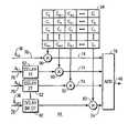
- FIG. 1shows a layout diagram of an exemplary environment in which a communication system 20 configured in accordance with the teaching of the present invention may be practiced.
- Communication system 20includes any number of transmitters (TX's) 22 (three shown) and any number of receivers (RX's) 24 (five shown).
- Transmitters 22wirelessly broadcast messages through RF time domain multiple access (TDMA) communication signals 26 which are receivable by receivers 24 located within radio coverage areas 28 for the transmitters 22 .
- Radio coverage areas 28may also be called cells or sectors. As illustrated in FIG. 1 , various ones of radio coverage areas 28 may be adjacent to one another and even overlap to some extent. In the preferred embodiment, a common spectrum is used in all radio coverage areas 28 so that communication system 20 has a frequency reuse pattern substantially equal to one.
- TDMAtime domain multiple access
- FIG. 1depicts only a forward link in which radio equipment is viewed as being only a transmitter 22 or a receiver 24 .
- a reverse linkmay also be implemented and that each item of equipment may have both a transmitter and receiver.
- the reverse linkmay use the same or a different spectrum from the forward link. If a forward link conforms to the teaching of the present invention, then the reverse link may or may not conform, and vice versa.
- FIG. 2shows a timing diagram, which depicts an exemplary temporal format for TDMA communication signal 26 .
- FIG. 2specifically depicts two frames 30 , each of which is temporally subdivided into any number of timeslots 32 .
- Different timeslots 32are preferably assigned to different receivers 24 ( FIG. 1 ) in a manner well understood in the art so that different recipients are distinguished from one another by being assigned to the different time slots 32 .
- TDMA communication signal 26consumes the entire common spectrum for each time slot 32 .
- Each time slot 32 of TDMA communication signal 26is subdivided into successive blocks 34 of symbols 36 .
- FIG. 2illustrates each of symbols 36 within a block 34 as being concurrently present throughout the entire duration of a block period because certain preferred embodiments discussed below configure symbols 36 to remain present for block periods.
- each symbol 36is independently spread using cyclic variations of the same common code 38 .
- the number M of symbols 36 in a blockmay equal the number N of chips in a spreading code, in which case the spreading factor equals one.
- performance improvementsresult when N is greater than M.
- FIG. 3shows a block diagram of a single transmitter 22 and a single receiver 24 configured in accordance with the teaching of the present invention. Those skilled in the art will appreciate that all transmitters 22 and receivers 24 may be configured similarly. In addition, any number of receivers 24 may, at any given instant, receive TDMA communication signal 26 from a given transmitter 22 and, in fact, may receive TDMA communication signals 26 from more than one transmitter 22 .
- Transmitter 22includes a TDMA modulation section 40 , which generates a TDMA-configured stream 42 of data conveying symbols 36 .
- Stream 42feeds a direct sequence spread spectrum (DSSS) modulation section 44 , which generates a composite signal 46 .
- Composite signal 46feeds a transmission section 48 , which forms TDMA communication signal 26 from composite signal 46 and wirelessly broadcasts TDMA communication signal 2 6 for reception by receivers 24 located within radio coverage area 28 ( FIG. 1 ) of transmitter 22
- any number of data sources 50supply digital data to a multiplexer (MUX) 52 .
- the digital data from data sources 50may be intended for any number of receivers 24 .
- Multiplexer 52groups the digital data so that data intended for different receivers 24 are serially fed to a cyclic redundancy check (CRC) section 54 in accordance with the assignment of timeslots 32 ( FIG. 2 ) to receivers 24 .
- CRC section 54provides forward error correction in a manner well understood by those skilled in the art.
- P/A block encoding section 60applies a type of encoding which primarily reduces the peak-to-average power ratio in composite signal 46 and thereby lessens the demands placed on a power amplifier included in transmission section 48 to faithfully reproduce communication signal 26 with a minimum amount of distortion. This type of encoding may, but is not required to, provide additional coding gain.
- P/A block encoding section 60when P/A block encoding section 60 is included, it applies block encoding so that encoded blocks coincide with successive blocks of symbols 36 ( FIG. 2 ), discussed above. In other words, the data are encoded so that P/A encoded blocks begin with symbol 36 a k,0 ( FIG. 2 ) and end with symbol 36 a k,m ( FIG. 2 ).
- P/A block encoding section 60feeds a constellation encoding section 62 which converts the data into complex symbols in accordance with a predetermined phase constellation.
- a constellation encoding section 62which converts the data into complex symbols in accordance with a predetermined phase constellation.
- each four-bit group of data output from P/A block encoding section 60may be mapped by section 62 into a single complex symbol having in-phase and quadrature components in accordance with a 16-QAM phase constellation.
- the present inventionmay be used with any type or size of phase constellation.
- the stream of complex symbols output from constellation encode section 62passes through a synchronization multiplexer (SYNC MUX) 64 , where a preamble 66 is inserted into the stream at appropriate intervals.
- Preamble 66is a known code which helps receivers 24 obtain synchronization and determine the timing of frames 30 and time slots 32 ( FIG. 2 ).
- the resulting TDMA-configured complex stream 42serves as the output from TDMA modulation section 40 and feeds DSSS modulation section 44 .
- a demultiplexer (DEMUX) 68divides TDMA-configured stream 42 of complex symbols 36 into blocks 34 ( FIG. 2 ) of symbols 36 .
- M unspread complex symbol substreams 70are provided by demultiplexer 68 so that each unspread substream 70 contributes a single complex symbol 36 during each block 34 , and each block 34 has a block period T*M, where T is the symbol period of TDMA-configured stream 42 .
- Unspread substreams 70feed a spreading section 72 .
- cyclic variations of common spreading code 38FIG. 2
- the M spread substreams 74may be passed through an optional peak-to-average (P/A) reduction section 76 which adjusts phase angles of the complex chips conveyed in the spread substreams 74 in a manner understood by those skilled in the art to reduce peak-to-average power ratio and lessen demands placed on a power amplifier.
- P/Apeak-to-average
- a combining section 78combines spread substreams 74 to form composite signal 46 .
- Various embodiments of DSSS modulation section 44are discussed in more detail below.
- Transmission section 48includes any number of components and functions well known to those skilled in the art. For example, scrambling section 56 and/or synchronization multiplexer 64 , discussed above, may be included in transmission section 48 rather than in TDMA modulation section 40 .
- a pulse shaping section(not shown) is desirably included in transmission section 48 to spread the energy from each chip over a number of chip intervals using a suitable filter which minimizes inter-symbol or inter-chip interference so that spectral constraints may be observed.
- Transmission section 48may also include digital-to-analog conversion, quadrature modulation, up-conversion, and power amplification functions, all implemented in conventional fashion.
- Power controlmay be implemented in transmission section 48 at the power amplifier to ameliorate a potential near-far problem, which should be much less pronounced in communication system 20 ( FIG. 1 ) than in traditional CDMA communication systems.
- TDMA communication signal 26is formed from composite signal 46 and wirelessly broadcast from transmission section 48 .
- Receiver 24receives TDMA communication signal 26 .
- communication signal 26is processed through a receiving section 80 and passed to a code division multiplex (CDM) to time division multiplex (TDM) converter 82 .
- CDM to TDM converter 82produces a baseband signal 84 , which is further demodulated in a TDM demodulation section 86 , with individual users receiving their respective data streams 88 .
- TDM demodulation section 86may simply provide a data stream intended for a single user.
- Receiving section 80includes any number of components and functions well known to those skilled in the art. For example, amplifying, filtering, and down-conversion may be performed to form an intermediate frequency (IF) signal.
- the IF signalmay be converted from an analog form into a digital form, and automatic gain control (AGC) may be provided.
- AGCautomatic gain control
- the digitized form of the down-converted communication signal 26passes to CDM to TDM converter 82 .
- CDM to TDM converter 82performs despreading and optionally performs equalization on the communication signal.
- Various embodiments of CDM to TDM converter 82are discussed in more detail below.
- TDM demodulation section 86includes any number of components and functions well known to those skilled in the art. For example, channel estimation and synchronization may be performed in TDM demodulation section 82 . A rake receiver and/or equalizer may be included. De-interleaving, error correction decoding, and descrambling are desirably performed, and preambles and other control data are evaluated to detect time slots assigned to the receiver 24 . These and other components and functions conventionally used in digital demodulators may be included in TDM demodulation section 86 .
- FIG. 4shows a timing diagram depicting how common spreading code 38 ( FIG. 2 ) is applied to blocks 34 ( FIG. 2 ) of unspread data substreams 70 ( FIG. 3 ) in accordance with first, second and third embodiments of DSSS modulation section 44 ( FIG. 3 ) in transmitter 22 ( FIG. 3 ).
- FIG. 4is presented in tabular form, with rows representing the application of the chips of common spreading code 38 to symbols 36 ( FIG. 2 ). Columns in FIG. 4 depict successive blocks 34 .
- spreading code 38is applied to unspread substreams 70 so that composite signal 46 is influenced, at least for a portion of the time, by symbols 36 from two different blocks 34 .
- FIG. 5shows a block diagram of the first embodiment of DSSS modulation section 44 .
- Demultiplexer 68is omitted from FIG. 5 for convenience.
- the unspread substream 70conveying symbols a k,0 experiences no delay before being fed to a first input of a multiplier 90 .
- the unspread substreams 70conveying symbols a k,1 through a k,M ⁇ 1 are respectively delayed in delay elements 92 by 1 through M ⁇ 1 symbol periods (T) before being fed to respective first inputs of other multipliers 90 .
- a spreading code generation section 94generates cyclic variations of common spreading code 38 .
- FIG. 5illustrates code generation section 94 in matrix form, which matrix takes on a cyclic Toeplitz form because the matrix elements hold cyclic variations of the same spreading code 38 .
- different columns of the matrixsupply code chips C o through C N ⁇ 1 to second inputs of respective multipliers 90 .
- Different rows of the matrixindicate different code chips to apply during different chip intervals. So long as the number (N) of chips in spreading code 38 is greater than or equal to the number (M) of symbols 36 per block 34 , different code chips of the same code are applied to different symbols during any and all chip intervals.
- Outputs of multipliers 90provide respective spread substreams 74 .
- FIG. 5omits depiction of optional P/A reduction section 76 ( FIG. 3 ) for convenience.
- Combining section 78takes the form of an adder, so that composite signal 46 during each chip interval equals the sum of M symbols 36 , with each of the M symbols being premultiplied by designated chips of common spreading code 38 .
- DSSS modulating section 44temporally offsets application of common spreading code 38 to unspread substreams 70 so that the resulting spread substreams 74 correspond to unspread substreams 70 modulated by cyclic variations of common spreading code 38 .
- FIG. 6shows a block diagram of the second embodiment of DSSS modulation section 44 .
- This second embodimentis equivalent to the first embodiment of FIG. 5 , but it is implemented differently.
- Demultiplexer 68FIG. 3
- spreading code generation section 94need not be implemented as a two-dimensional matrix having a different row to define the different chips to be applied during different chip intervals, as discussed above in connection with FIG. 5 . Rather, spreading code generation section 94 may be implemented as a one-dimensional matrix having different columns, and only one of those columns is simultaneously applied to different unspread substreams 70 .
- Spreading code generation section 94may be implemented as a shift register configured to shift cyclically at the chip rate.
- FIG. 7shows a block diagram of the third embodiment of DSSS modulating section 44 .
- This third embodimentis also equivalent to the first embodiment of FIG. 5 , but is implemented differently.
- This third embodimentis a finite impulse response (FIR) implementation.
- symbol stream 42( FIG. 3 ) is fed to a series of delay elements 96 , each of which imparts a one-chip interval delay.
- the series of delay elements 96serves the role of demultiplexer 68 ( FIG. 3 ) in this third embodiment, with the input to the first delay element 96 and the outputs of all delay elements 96 providing unspread substreams 70 .
- Delay elements 92FIGS. 5-6 ) from the first and second embodiments of spreading section 72 are omitted.
- Spreading code generation section 94simply provides common spreading code 38 , and need not be cycled because unspread substreams 70 to which spreading code 38 is applied are configured to perform the temporal offsetting requirements. Accordingly, symbol delay elements 92 are omitted and spreading code generating section 94 need not cycle the common spreading code or explicitly provide separate versions of spreading code 38 to separate unspread substreams 70 . Nevertheless, in this third embodiment of DSSS modulation section 44 , spreading section 72 temporally offsets application of common spreading code 38 by sequentially delaying symbols 36 to form unspread substreams 70 and applying spreading code 38 to the delayed symbols in unspread substreams 70 so that the resulting spread substreams 74 correspond to unspread substreams 70 modulated by cyclic variations of common spreading code 38 .
- CDM to TDM converter 82includes a pulse shaping matched filter 98 , the output of which feeds a mismatched filter 100 .
- Pulse shaping matched filter 98complements a pulse shaping filter (not shown) desirably implemented in transmission section 48 of transmitter 22 ( FIG. 3 ) to optimize signal-to-noise ratio and band-limit the signal.
- Pulse shaping matched filter 98is desirably implemented using conventional techniques known to those skilled in the art.
- Mismatched filter 100accomplishes two functions. One function is despreading and the other function is sidelobe suppression. In fact, mismatched filter 100 is desirably implemented to correspond to a spreader matched filter 102 upstream of a sidelobe suppression filter 104 . One technique for implementing mismatched filter 100 is simply to implement two filters coupled in series for the despreading and sidelobe suppression functions. In another technique (not shown) the two functions may be combined in a common filter.
- Mismatched filter 100experiences a signal-to-noise ratio typically worse than that of a matched filter.
- mismatched filter 100is desirably configured to achieve a relative efficiency of greater than 60%, and more preferably greater than 90%, compared to a matched filter.
- common spreading code 38is a strong determinant of the relative efficiency of mismatched filter 100 .
- conventional orthogonal pseudonoise (PN) codes commonly used in conventional CDMA applicationsare unacceptable because their mismatched filters achieve relative efficiencies roughly around only 50%.
- Barker codesmake suitable codes because of aperiodic autocorrelation sidelobes having magnitudes less than or equal to one.
- the limited length (i.e., N ⁇ 13) and/or prime numbered length of many Barker codesproves a detriment.
- other codes having a greater length and slightly greater aperiodic autocorrelation sidelobes, such as magnitudes less than or equal to two or threeare acceptable and may be easily derived by those skilled in the art.
- FIG. 9shows an exemplary spectral analysis of a suitable spreading code usable in connection with the present invention.
- FIG. 9represents an arbitrary code for which a spectral analysis can be performed using a time-frequency domain transformation, such as a Fourier transform. While a code having a precisely flat spectral analysis result is not a requirement, better results are achieved when no frequency bin shows substantially more or less signal level than other bins, as depicted in FIG. 9 .
- the signal level in each binis desirably within ⁇ 25% of the average signal level taken over all bins. In particular, for best results no bins should exhibit a nearly zero signal level.
- mismatched filter 100 illustrated in FIG. 8will be readily understood by those skilled in the art.
- Spreader matched filter 102may be implemented using the complex conjugate of spreading code 38 ( FIG. 2 ) presented in a reverse order.
- Sidelobe suppression filter 104may be implemented using well-known FFT or linear programming techniques.
- the output of spreader matched filter 102 in mismatched filter 100is a composite signal 106 equivalent to the autocorrelation function applied to each of the M unspread and spread substreams 70 and 74 (FIGS. 3 and 5 - 7 ) discussed above.
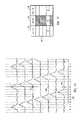
- FIG. 10shows an exemplary timing diagram of the various individual signal components present in composite signal 106 output from the matched filter 102 portion of mismatched filter 100 .
- FIG. 10depicts an exemplary situation where the number of substreams 70 and 74 (i.e., M) equals seven and the number (i.e., N) of chips in spreading code 38 equals seven.
- Mthe number of substreams 70 and 74
- Nthe number of chips in spreading code 38 equals seven.
- each row in FIG. 10represents one of the seven substreams, and each row depicts autocorrelation with an assumed rectangular pulse.
- composite signal 106is the sum of all rows in FIG. 10 rather than seven distinct signals.
- the output sidelobe suppression filter 104provides baseband signal 84 , which also serves as the output of CDM to TDM converter 82 .
- Baseband signal 84is routed to TDM demodulation section 86 .
- a rake receiver(not shown) or equalizer (not shown) may be used in TDM demodulation section 86 to compensate for the multipath. While some inefficiency may result from using a mismatched filter to despread communication signal 26 , any such inefficiency is more than compensated for by a marked improvement in multipath tolerance.
- receiver 24While receiver 24 receives a communication signal 26 from one transmitter 22 , it may simultaneously receive other communication signals 26 from other transmitters 22 in adjacent radio coverage areas 28 ( FIG. 1 ).
- Conventional CDMA techniquesmay be used to prevent interference between such diverse communication signals 26 .
- different spreading codes 38may be selected for use at different transmitters 22 .
- Such different spreading codes 38are desirably configured to have low cross-correlation sidelobes among all spreading codes 38 . If this option is selected, only a few (e.g., 3-7) of such codes need be used to prevent interference because interference should not be a problem between communication signals 26 from non-adjacent radio coverage areas 28 ( FIG. 1 ).
- transmitter 22 and receiver 24may include other stages to further scramble/descramble spread spectrum signals using other spreading codes.
- FIG. 1shows a timing diagram depicting how common spreading code 38 ( FIG. 2 ) is applied to blocks 34 ( FIG. 2 ) of unspread data substreams 70 ( FIG. 3 ) in accordance with fourth and fifth embodiments of DSSS modulation section 44 ( FIG. 3 ) in transmitter 22 ( FIG. 3 ).
- FIG. 11is presented in tabular form, with rows representing the application of the chips of common spreading code 38 to symbols 36 ( FIG. 2 ). Columns in FIG. 11 depict successive blocks 34 .
- spreading code 38 in the fourth and fifth embodimentsis applied to unspread substreams 70 so that composite signal 46 is influenced, at all times, by symbols 36 from only common blocks 34 .
- FIG. 12shows a block diagram of the fourth and fifth embodiments of DSSS modulation section 44 .
- Demultiplexer 68( FIG. 3 ) is omitted from FIG. 12 for convenience.
- FIG. 12represents that N symbols 36 (i.e. a k,0 through a k,N ⁇ 1 ) are provided from demultiplexer 68 during each block 34 ( FIG. 2 ).
- FIG. 12represents that the number (M) of symbols 36 per block 34 equals the number (N) of chips in spreading code 38 .
- the number M of symbols 36 per block 34may be made equal to N by padding with zeros so that the zeros are evenly distributed among the symbols 36 .
- Mthe number of symbols 36 per block 34 may be made equal to N by padding with zeros so that the zeros are evenly distributed among the symbols 36 .
- Mthe number of symbols 36 per block 34 may be made equal to N by padding with zeros so that the zeros are evenly distributed among the symbols 36 .
- Mthe number of symbols 36 per block 34 may be made equal to N by padding with zeros so that the zeros are evenly distributed among the symbols 36 .
- M4 and N equals 12 symbols 36 may be provided by following each symbol 36 in each block 34 with two zeros.
- Unspread substreams 70which provide N symbols 36 per block 34 , pass to an optional time-frequency domain transformation section 110 .
- Time-frequency domain transformation section 110may be implemented as an inverse fast Fourier transform (IFFT).
- IFFTinverse fast Fourier transform
- the fourth embodiment of DSSS modulation section 44shall be deemed to omit section 110
- the fifth embodimentshall be deemed to include section 110 .
- unspread substreams 70convey time domain data to spreading section 72 in the fourth embodiment and frequency domain data to spreading section 72 in the fifth embodiment.
- section 110is not a requirement of the present invention, certain benefits may be achieved by the addition of section 110 as will be discussed below. Moreover, section 110 , or the equivalent, is conventionally included in digital communication transmitters which implement an orthogonal frequency division multiplexed (OFDM) modulation format. In such situations, section 110 may be present for use in connection with the present invention at little additional complexity or expense.
- OFDMorthogonal frequency division multiplexed
- Delay elements 92are omitted in the fourth and fifth embodiments of DSSS modulation section 44 to permit only symbols 36 concurrently present during a common block 34 to influence composite signal 46 .
- spreading section 72 and spreading code generating section 94are implemented in a manner similar to that discussed above in connection with the first and second embodiments of DSSS modulation section 44 ( FIGS. 5-6 ).
- cyclic variations of a single common spreading code 38are applied in the form of a cyclic Toeplitz matrix (see FIG. 5 ).
- spreading code generating section 94acts to multiply the 1 ⁇ N matrix of symbols 36 in each block 34 by spreading code 38 effectively in the form of an N ⁇ N cyclic Toeplitz matrix, it may do so simply through a one-dimensional matrix having different columns applied to different unspread substreams 70 at different multipliers 90 .
- the fourth and fifth embodiments of DSSS modulation section 44are better served with a spreading code 38 having low periodic autocorrelation sidelobes and a substantially flat spectrum.
- Spreading code generation section 94may be implemented as a shift register configured to shift cyclically at the chip rate.
- Spread substreams 74 output from multipliers 90are combined in an adding circuit 78 to form a pre-composite signal 46 ′, which is converted back into parallel streams at a demultiplexer (DEMUX) 112 into N chips per block 34 , labeled b k,0 through b k,N ⁇ 1 in FIG. 12 .
- DEMUXdemultiplexer
- Demultiplexer 112provides one technique for forming a cyclic prefix 114 .
- Chips b k,0 through b k,N ⁇ 1 and cyclic prefix 114are routed in parallel to inputs of a multiplexer (MUX) 116 for conversion into serial composite signal 46 .
- MUXmultiplexer
- chips b k,0 through b k,N ⁇ 1are associated with an intended order, in which chips b k,0 , b k,1 , b k,2 , . . . b k,P occur first in pre-composite signal 46 ′, and chips b k,q , . . .
- the clock rate of multiplexer 116is desirably sufficiently higher than the clock chip rate to accommodate cyclic prefix 114 .
- Transmission section 48forms blocks 34 of communication signal 26 from blocks 34 of composite signal 46 .
- Blocks 34 of communication signal 26propagate to receiver 24 through a communication channel, which may be unique to a specific transmitter 22 location and receiver 24 location.
- Blocks 34 of communication signal 26experience multipath and other types of distortion when propagating through this channel. The mathematical effect of this distortion is equivalent to multiplying composite signal 46 by the transfer function of the channel, which imposes the multipath.
- each block 34 of composite signal 46is formed from the matrix multiplication of the spreading code 38 with a block 34 of symbols 36 .
- the effect of multipath distortionis then the matrix multiplication of the matrix expression of the channel transfer function with this matrix product.
- a matrix multiplicationdoes not observe a communicative mathematical property.
- the product of the channel transfer function by the spreading matrixdoes not necessarily equal the product of spreading matrix by the channel transfer function.
- FIG. 13shows a second embodiment of CDM to TDM converter 82 for use with the fourth embodiment of the DSSS modulation section 44 (i.e., the time domain embodiment).
- the digitized IF form of communication signal 26after being distorted through the communication channel, is applied to a demultiplexer (DEMUX) 118 and a synchronization (SYNC) section 120 .
- An output of synchronization section 120feeds a cyclic prefix removal section 122 of demultiplexer 118 .
- Synchronization section 120identifies the start of blocks 34 , and cyclic prefix removal section 122 removes the first-occurring p chips from each block 34 .
- the last-occurring p chipsduplicate the first-occurring p chips, and the last-occurring p chips and all other chips remain in each block 34 .
- the first-occurring p chipsare removed because they are influenced by multipath from the previous block 34 of communication signal 26 . All chips, which remain in each block 34 , are influenced only by multipath from that block 34 .
- cyclic prefix 114As discussed above, due to the use of cyclic variations of spreading code 38 to spread symbols 36 and the inclusion of cyclic prefix 114 , the matrix multiplication which characterizes the channel now observes the communicative mathematical property. Consequently, despreading may occur before equalization.
- Despreadingmay take place using a despreading code generator 124 , a despreading section 126 , and a combining section 128 .
- Despreading code generator 124 , despreading section 126 , and combining section 128are identical in structure to spreading code generator 94 , spreading section 72 , and combining section 78 in DSSS modulator section 44 of transmitter 22 ( FIG. 12 ), with the despreading code generated in despreading code generator 124 being related to spreading code 38 .
- despreading code chips D nIFFT(1/FFT(C n )), where IFFT and FFT denote inverse fast Fourier transform and fast Fourier transform, respectively, and C n represents the chips of spreading code 38 .
- Spread substreams 130are provided by demultiplexer 118 to multipliers 132 in despreading section 126 along with the despreading code matrix from despreading code generator 124 .
- the despreading codeis applied in the form of a cyclic Toeplitz matrix due to the use of cyclic variations of a common spreading code to which the despreading code is related.
- Multipliers 132provide despread substreams 134 to combiner 128 to add despread substreams 134 on a chip by chip basis into a serial pre-composite baseband signal 136 .
- Pre-composite baseband signal 136is converted into parallel symbol substreams 140 at a demultiplexer (DEMUX) 138 , and symbol substreams 140 are applied to a maximum likelihood sequence estimation (MLSE) equalizer 142 or the equivalent.
- MLSE equalizer 142may also be called a Viterbi equalizer.
- Parallel outputs from MLSE equalizer 142feed a multiplexer (MUX) 144 which converts the parallel symbol substreams into baseband signal 84 for further processing by TDM demodulation section 86 ( FIG. 3 ).
- MUXmultiplexer
- an MLSE equalizeris a simple structure, which is stable and can be effectively configured to compensate for multipath.
- the coupling of MLSE equalizer 142 downstream of despreading section 126is possible due to the use of cyclic variations of common spreading code 38 in transmitter 22 and cyclic prefix 114 to enable matrix multiplication exhibiting the mathematical communicative property.
- FIG. 14shows a third embodiment of CDM to TDM converter 82 for use with the fifth embodiment of DSSS modulation section 44 (i.e., the frequency domain embodiment), discussed above in connection with FIG. 12 .
- the digitized IF form of communication signal 26after being distorted through the communication channel, is applied to demultiplexer (DEMUX) 118 and synchronization (SYNC) section 120 , as discussed above in connection with FIG. 13 .
- DEMUXdemultiplexer
- SYNCsynchronization
- time-frequency domain transformation section 146which complements time-frequency domain transformation section 110 ( FIG. 12 ).
- time-frequency domain transformation section 110 in DSSS modulation section 44implements an inverse fast Fourier transform (IFFT)
- time-frequency domain transformation section 146desirably implements a fast Fourier transform (FFT).
- IFFTinverse fast Fourier transform
- FFTfast Fourier transform
- Mismatched filter 100couples downstream of time-frequency domain transformation section 146 .
- mismatched filter 100may be implemented in a manner that joins despreading and equalization functions in a common frequency domain equalizer.
- coefficients for the frequency domain equalizertake the form D* H(n) /D C(n) , where represents despreading code chips that are related to spreading code 38 in the manner discussed above in connection with FIG. 13 and D* H(n) represents the complex conjugate of the transfer function of the channel.
- D* H(n)represents the complex conjugate of the transfer function of the channel.
- One reason why a frequency domain equalizer is easy and effective to implementis that coefficients are not proportional to the inverse of the transfer function of the channel.
- despreading code chipsare related to the inverse of the FFT of the spreading code, such coefficients do not pose problems because the designer controls the FFT of the code through code selection, and a spreading code having a substantially flat spectral response may be selected, as discussed above in connection with FIG. 9 .
- Parallel outputs of mismatched filter 100pass in parallel to hard decision sections 148 , and parallel outputs of hard decision sections 148 are combined into serial baseband signal 84 in multiplexer (MUX) 144 for further processing in TDM demodulation section 86 ( FIG. 3 ).
- MUXmultiplexer
- mismatched filter 100may reside downstream of time-frequency transformation section 146 , which improves the efficacy and simplicity of the equalization and despreading functions.
- the present inventionprovides an improved method and apparatus for wireless communications.
- the present inventioncontemplates the combination of TDMA and spread spectrum techniques so that wireless communications capacity is increased over the capacities achievable through conventional TDMA and/or CDMA systems using an equivalent amount of spectrum.
- robust, simple, and inexpensive processing techniquesare usable in the present invention, making the present invention suitable for hubs, subscriber units, mobile stations, fixed stations, portable stations, and the like.
- the present inventionmay be adapted to and used in conjunction with a variety of modulation and multiple access techniques, such as frequency division multiple access (FDMA) and orthogonal frequency division multiplexing (OFDM).
- FDMAfrequency division multiple access
- OFDMorthogonal frequency division multiplexing
- the advantages and improvements of the present inventionare achieved, at least in part through the use of a composite RF communication signal which includes signal components obtained by modulating diverse branches of a single user's data stream using cyclic variants of a common spreading code.
- the present inventionis configured to tolerate self-interference and is better able to tolerate multipath than conventional DSSS-CDMA communication systems.
- ultra-wideband (UWB) communication technologyemploys discrete pulses of electromagnetic energy that are emitted at, for example, nanosecond or picosecond intervals (generally tens of picoseconds to hundreds of nanoseconds in duration). For this reason, ultra-wideband is often called “impulse radio.” That is, the UWB pulses may be transmitted without modulation onto a sine wave, or a sinusoidal carrier, in contrast with conventional carrier wave communication technology. Thus, UWB generally requires neither an assigned frequency nor a power amplifier.
- IEEE 802.11ais a wireless local area network (LAN) protocol, which transmits a sinusoidal radio frequency signal at a 5 GHz center frequency, with a radio frequency spread of about 5 MHz.
- LANwireless local area network
- a carrier waveis an electromagnetic wave of a specified frequency and amplitude that is emitted by a radio transmitter in order to carry information.
- the 802.11 protocolis an example of a carrier wave communication technology.
- the carrier wavecomprises a substantially continuous sinusoidal waveform having a specific narrow radio frequency (5 MHz) that has a duration that may range from seconds to minutes.
- an ultra-wideband (UWB) pulsemay have a 2.0 GHz center frequency, with a frequency spread of approximately 4 GHz, as shown in FIG. 16 , which illustrates two typical UWB pulses.
- FIG. 16illustrates that the shorter the UWB pulse in time, the broader the spread of its frequency spectrum. This is because bandwidth is inversely proportional to the time duration of the pulse.
- a 600-picosecond UWB pulsecan have about a 1.8 GHz center frequency, with a frequency spread of approximately 1.6 GHz and a 300-picosecond UWB pulse can have about a 3 GHz center frequency, with a frequency spread of approximately 3.2 GHz.
- UWB pulsesgenerally do not operate within a specific frequency, as shown in FIG. 15 .
- either of the pulses shown in FIG. 16may be frequency shifted, for example, by using heterodyning, to have essentially the same bandwidth but centered at any desired frequency.
- UWB pulsesare spread across an extremely wide frequency range, UWB communication systems allow communications at very high data rates, such as 100 megabits per second or greater.
- the power sampled in, for example, a one megahertz bandwidthis very low.
- UWB pulses of one nano-second duration and one milliwatt average power (0 dBm)spreads the power over the entire one gigahertz frequency band occupied by the pulse.
- the resulting power densityis thus 1 milliwatt divided by the 1,000 MHz pulse bandwidth, or 0.001 milliwatt per megahertz ( ⁇ 30 dBm/MHz).
- UWB pulsesmay be transmitted at relatively low power density (milliwatts per megahertz).
- an alternative UWB communication systemmay transmit at a higher power density.
- UWB pulsesmay be transmitted between 30 dBm to ⁇ 50 dBm.
- UWBultra-wideband
- the April 22 Report and Orderrequires that UWB pulses, or signals occupy greater than 20% fractional bandwidth or 500 megahertz, whichever is smaller.
- Fractional bandwidthis defined as 2 times the difference between the high and low 10 dB cutoff frequencies divided by the sum of the high and low 10 dB cutoff frequencies.
- UWB communication methodsmay transmit UWB pulses that occupy 500 MHz bands within the 7.5 GHz FCC allocation (from 3.1 GHz to 10.6 GHz).
- UWB pulseshave about a 2-nanosecond duration, which corresponds to about a 500 MHz bandwidth.
- the center frequency of the UWB pulsescan be varied to place them wherever desired within the 7.5 GHz allocation.
- IFFTInverse Fast Fourier Transform
- the resultant UWB pulse, or signalis approximately 506 MHz wide, and has a 242 nanosecond duration. It meets the FCC rules for UWB communications because it is an aggregation of many relatively narrow band carriers rather than because of the duration of each pulse.
- OFDMOrthogonal Frequency Division Multiplexing
- UWB pulse durationsmay vary from 2 nanoseconds, which occupies about 500 MHz, to about 133 picoseconds, which occupies about 7.5 GHz of bandwidth. That is, a single UWB pulse may occupy substantially all of the entire allocation for communications (from 3.1 GHz to 10.6 GHz).
- Yet another UWB communication method being evaluated by the IEEE standards committeescomprises transmitting a sequence of pulses that may be approximately 0.7 nanoseconds or less in duration, and at a chipping rate of approximately 1.4 giga pulses per second.
- the pulsesare modulated using a Direct-Sequence modulation technique, and is called DS-UWB. Operation in two bands is contemplated, with one band is centered near 4 GHz with a 1.4 GHz wide signal, while the second band is centered near 8 GHz, with a 2.8 GHz wide UWB signal. Operation may occur at either or both of the UWB bands. Data rates between about 28 Megabits/second to as much as 1,320 Megabits/second are contemplated.
- UWBwireless ultra-wideband
- an ultra-wideband (CUB) communication systemFor example, one embodiment of an UWB communication system divides a stream of data conveying symbols into a plurality of unspread substreams. A common spreading code is generated at the ultra-wideband transmitter, and each of the unspread substreams are spread using the common spreading code to form a plurality of spread substreams. The spread substreams are combined to form a composite signal that is transmitted using a plurality of discrete electromagnetic pulses.
- an ultra-wideband communication systemcomprises a demultiplexer for dividing a stream of data conveying symbols into a plurality of unspread substreams.
- a spreading sectionis coupled to the demultiplexer and configured to generate a plurality of spread substreams from the plurality of unspread substreams.
- a combining sectionis coupled to the spreading section and configured to form a composite signal from the plurality of spread substreams, and a transmission section is coupled to the combining section and configured to transmit the composite signal over an ultra-wideband communication channel.
- the UWB devices, systems and/or methods in the above-described embodimentscommunicate with each other by transmitting and receiving a plurality of discrete electromagnetic pulses, as opposed to a substantially continuous carrier wave.
- Each pulsemay have a duration that can range between about 10 picoseconds to about 1 microsecond, and a power that may range between about +30 dBm to about ⁇ 60 dBm, as measured at a single frequency.
- the present inventionmay be employed in any type of network, be it wireless, wire, or a mix of wire media and wireless components. That is, a network may use both wire media, such as coaxial cable, and wireless devices, such as satellites, or cellular antennas.
- a networkis a group of points or nodes connected by communication paths. The communication paths may use wires or they may be wireless.
- a network as defined hereincan interconnect with other networks and contain sub-networks.
- a network as defined hereincan be characterized in terms of a spatial distance, for example, such as a local area network (LAN), a personal area network (PAN), a metropolitan area network (MAN), a wide area network (WAN), and a wireless personal area network (WPAN), among others.
- LANlocal area network
- PANpersonal area network
- MANmetropolitan area network
- WANwide area network
- WPANwireless personal area network
- a network as defined hereincan also be characterized by the type of data transmission technology used by the network, such as, for example, a Transmission Control Protocol/Internet Protocol (TCP/IP) network, a Systems Network Architecture network, among others.
- a network as defined hereincan also be characterized by whether it carries voice, data, or both kinds of signals.
- a network as defined hereinmay also be characterized by users of the network, such as, for example, users of a public switched telephone network (PSTN) or other type of public network, and private networks (such as within a single room or home), among others.
- PSTNpublic switched telephone network
- a network as defined hereincan also be characterized by the usual nature of its connections, for example, a dial-up network, a switched network, a dedicated network, and a non-switched network, among others.
- a network as defined hereincan also be characterized by the types of physical links that it employs, for example, optical fiber, coaxial cable, a mix of both, unshielded twisted pair,
- the present inventionmay be employed in any type of wireless network, such as a wireless PAN, LAN, MAN, or WAN.
- the present inventionmay be employed in wire media, as the present invention dramatically increases the bandwidth of conventional networks that employ wire media, such as hybrid fiber-coax cable networks, or CATV networks, yet it can be inexpensively deployed without extensive modification to the existing wire media network.
Landscapes
- Engineering & Computer Science (AREA)
- Computer Networks & Wireless Communication (AREA)
- Signal Processing (AREA)
- Mobile Radio Communication Systems (AREA)
- Dc Digital Transmission (AREA)
Abstract
Description
Claims (3)
Priority Applications (3)
| Application Number | Priority Date | Filing Date | Title |
|---|---|---|---|
| US10/961,592US7339955B2 (en) | 2000-09-25 | 2004-10-08 | TDMA communication method and apparatus using cyclic spreading codes |
| PCT/US2005/034649WO2006041681A2 (en) | 2004-10-08 | 2005-09-28 | Ultra-wideband communication systems and methods |
| US11/978,049US20080225963A1 (en) | 2000-09-25 | 2007-10-25 | Ultra-wideband communication systems and methods |
Applications Claiming Priority (2)
| Application Number | Priority Date | Filing Date | Title |
|---|---|---|---|
| US09/670,054US7031371B1 (en) | 2000-09-25 | 2000-09-25 | CDMA/TDMA communication method and apparatus for wireless communication using cyclic spreading codes |
| US10/961,592US7339955B2 (en) | 2000-09-25 | 2004-10-08 | TDMA communication method and apparatus using cyclic spreading codes |
Related Parent Applications (1)
| Application Number | Title | Priority Date | Filing Date |
|---|---|---|---|
| US09/670,054Continuation-In-PartUS7031371B1 (en) | 2000-09-25 | 2000-09-25 | CDMA/TDMA communication method and apparatus for wireless communication using cyclic spreading codes |
Related Child Applications (1)
| Application Number | Title | Priority Date | Filing Date |
|---|---|---|---|
| US11/978,049ContinuationUS20080225963A1 (en) | 2000-09-25 | 2007-10-25 | Ultra-wideband communication systems and methods |
Publications (2)
| Publication Number | Publication Date |
|---|---|
| US20050068932A1 US20050068932A1 (en) | 2005-03-31 |
| US7339955B2true US7339955B2 (en) | 2008-03-04 |
Family
ID=36148786
Family Applications (2)
| Application Number | Title | Priority Date | Filing Date |
|---|---|---|---|
| US10/961,592Expired - Fee RelatedUS7339955B2 (en) | 2000-09-25 | 2004-10-08 | TDMA communication method and apparatus using cyclic spreading codes |
| US11/978,049AbandonedUS20080225963A1 (en) | 2000-09-25 | 2007-10-25 | Ultra-wideband communication systems and methods |
Family Applications After (1)
| Application Number | Title | Priority Date | Filing Date |
|---|---|---|---|
| US11/978,049AbandonedUS20080225963A1 (en) | 2000-09-25 | 2007-10-25 | Ultra-wideband communication systems and methods |
Country Status (2)
| Country | Link |
|---|---|
| US (2) | US7339955B2 (en) |
| WO (1) | WO2006041681A2 (en) |
Cited By (6)
| Publication number | Priority date | Publication date | Assignee | Title |
|---|---|---|---|---|
| US20080100496A1 (en)* | 1998-03-23 | 2008-05-01 | Time Domain Corporation | System and method for person or object position location utilizing impulse radio |
| US20090022233A1 (en)* | 2005-04-18 | 2009-01-22 | Matsushita Electric Industrial Co., Ltd | Radio receiving apparatus and radio receiving method |
| US20090045997A1 (en)* | 2007-08-13 | 2009-02-19 | Honeywell International Inc. | Method and system for communicating using pulsed radar signal data links |
| US20090097579A1 (en)* | 2007-10-16 | 2009-04-16 | Samsung Electronics Co. Ltd. | Apparatus and method for reducing papr in an ofdm system |
| US20160029288A1 (en)* | 2001-04-25 | 2016-01-28 | Koninklijke Philips N.V. | Radio communication system |
| US10957830B2 (en) | 2011-06-24 | 2021-03-23 | Cree, Inc. | High voltage monolithic LED chip with improved reliability |
Families Citing this family (18)
| Publication number | Priority date | Publication date | Assignee | Title |
|---|---|---|---|---|
| KR100782204B1 (en)* | 2000-12-29 | 2007-12-05 | 엘지전자 주식회사 | Code pair generation and code allocation method according to LS code selection |
| US20070129761A1 (en) | 2002-04-08 | 2007-06-07 | Ardian, Inc. | Methods for treating heart arrhythmia |
| US20050035663A1 (en)* | 2003-07-31 | 2005-02-17 | Steven Moore | Electromagnetic pulse generator |
| US7304977B2 (en)* | 2004-02-17 | 2007-12-04 | Texas Instruments Incorporated | Implementation for a 5 sample guard interval for multi-band OFDM |
| US7257151B2 (en)* | 2004-05-05 | 2007-08-14 | Texas Instruments Incorporated | (Updated) preamble for FDMA |
| US7903722B2 (en)* | 2005-01-14 | 2011-03-08 | Thomson Licensing | Hardware-efficient searcher architecture for code division multiple access (CDMA) cellular receivers |
| US8059776B2 (en)* | 2005-01-14 | 2011-11-15 | Thomson Licensing | Method and system for sub-chip resolution for secondary cell search |
| US20080137846A1 (en)* | 2005-01-14 | 2008-06-12 | Alton Shelborne Keel | Ram- Based Scrambling Code Generator for Cdma |
| US20070297493A1 (en)* | 2005-01-14 | 2007-12-27 | Keel Alton S | Efficient Maximal Ratio Combiner for Cdma Systems |
| CN101103547A (en)* | 2005-01-14 | 2008-01-09 | 汤姆森特许公司 | Cell search using rake searcher performing scrambling code determination |
| US7782925B2 (en)* | 2005-08-31 | 2010-08-24 | Freescale Semiconductor, Inc. | Method and device for generating high frequency waveforms |
| US8019435B2 (en) | 2006-05-02 | 2011-09-13 | Boston Scientific Scimed, Inc. | Control of arterial smooth muscle tone |
| US7831002B2 (en)* | 2006-10-11 | 2010-11-09 | The Boeing Company | System, apparatus and method for synchronizing a spreading sequence transmitted during a plurality of time slots |
| TWI387236B (en)* | 2007-08-31 | 2013-02-21 | Univ Yuan Ze | A multicarrier spread spectrum device using cyclic-shift orthogonal keying, transmitter, receiver, and communication system thereof |
| US8018906B2 (en)* | 2007-09-25 | 2011-09-13 | Terrace Communications Corporation | Symbol interleave for wireless communications |
| US8976842B1 (en)* | 2012-11-02 | 2015-03-10 | Comtech Ef Data Corp. | PN code sync detection and carrier frequency offset estimation for the direct sequence spread spectrum receiver |
| US9106321B2 (en) | 2013-09-30 | 2015-08-11 | Qualcomm Incorporated | Receive filters to minimize side lobes in a UWB system |
| CN106301419B (en)* | 2015-06-04 | 2019-05-28 | 华为技术有限公司 | Radio frequency interference removing method and device |
Citations (30)
| Publication number | Priority date | Publication date | Assignee | Title |
|---|---|---|---|---|
| US5177767A (en)* | 1990-03-06 | 1993-01-05 | Canon Kabushiki Kaisha | Spread-spectrum communication system |
| US5377223A (en)* | 1993-08-30 | 1994-12-27 | Interdigital Technology Corporation | Notch filtering a spread spectrum signal using fourier series coefficients |
| US5416767A (en)* | 1993-02-08 | 1995-05-16 | U.S. Philips Corporation | Method of transmitting a data stream, transmitter and receiver |
| US5467367A (en)* | 1991-06-07 | 1995-11-14 | Canon Kabushiki Kaisha | Spread spectrum communication apparatus and telephone exchange system |
| US5563909A (en) | 1993-12-15 | 1996-10-08 | Fujitsu Limited | Radio communication system |
| US5675572A (en) | 1993-07-28 | 1997-10-07 | Sony Corporation | Orthogonal frequency division multiplex modulation apparatus and orthogonal frequency division multiplex demodulation apparatus |
| US5677927A (en)* | 1994-09-20 | 1997-10-14 | Pulson Communications Corporation | Ultrawide-band communication system and method |
| US5852770A (en)* | 1995-09-19 | 1998-12-22 | Sanyo Electric Co., Ltd. | Transmission power control device for a portable terminal |
| US5943331A (en)* | 1997-02-28 | 1999-08-24 | Interdigital Technology Corporation | Orthogonal code synchronization system and method for spread spectrum CDMA communications |
| US5949813A (en) | 1994-07-12 | 1999-09-07 | Usa Digital Radio Partners, Lp | Method and system for simultaneously broadcasting and receiving digital and analog signals |
| US5978412A (en)* | 1996-08-12 | 1999-11-02 | Nec Corporation | Spread spectrum communication system |
| US6049707A (en) | 1997-09-02 | 2000-04-11 | Motorola, Inc. | Broadband multicarrier amplifier system and method using envelope elimination and restoration |
| US6078576A (en)* | 1998-02-04 | 2000-06-20 | Golden Bridge Technology, Inc. | High processing gain CDMA/TDMA system and method |
| US6108317A (en)* | 1995-11-01 | 2000-08-22 | Stm Wireless, Inc. | Cyclic code phase multiple access for inbound satellite communications |
| US6133876A (en)* | 1998-03-23 | 2000-10-17 | Time Domain Corporation | System and method for position determination by impulse radio |
| US6192068B1 (en) | 1996-10-03 | 2001-02-20 | Wi-Lan Inc. | Multicode spread spectrum communications system |
| US6356607B1 (en)* | 1995-06-05 | 2002-03-12 | Omnipoint Corporation | Preamble code structure and detection method and apparatus |
| US6392500B1 (en)* | 1999-04-27 | 2002-05-21 | Sicom, Inc. | Rotationally invariant digital communications |
| USRE37802E1 (en) | 1992-03-31 | 2002-07-23 | Wi-Lan Inc. | Multicode direct sequence spread spectrum |
| US20020159425A1 (en)* | 2000-03-17 | 2002-10-31 | Mitsuru Uesugi | Radio communication apparatus and radio communication method |
| US6549567B1 (en)* | 1994-09-20 | 2003-04-15 | Time Domain Corporation | Full duplex ultrawide-band communication system and method |
| US20030091100A1 (en)* | 2000-06-22 | 2003-05-15 | Hassan El Nahas El Homsi | Method and device for radio signal reception |
| US20030161411A1 (en)* | 1997-12-12 | 2003-08-28 | Mccorkle John W. | Ultra wide bandwidth communications method and system |
| US6690741B1 (en)* | 1997-05-16 | 2004-02-10 | Multispectral Solutions, Inc. | Ultra wideband data transmission system and method |
| US6952456B1 (en)* | 2000-06-21 | 2005-10-04 | Pulse-Link, Inc. | Ultra wide band transmitter |
| US20060039317A1 (en)* | 1999-12-30 | 2006-02-23 | Infineon Technologies Ag | Method and apparatus to support multi standard, multi service base-stations for wireless voice and data netwoks |
| US7076168B1 (en)* | 1998-02-12 | 2006-07-11 | Aquity, Llc | Method and apparatus for using multicarrier interferometry to enhance optical fiber communications |
| US7088795B1 (en)* | 1999-11-03 | 2006-08-08 | Pulse-Link, Inc. | Ultra wide band base band receiver |
| US20060291537A1 (en)* | 1999-06-14 | 2006-12-28 | Time Domain Corporation | Time transfer utilizing ultra wideband signals |
| US7206349B2 (en)* | 2000-02-22 | 2007-04-17 | Koninklijke Philips Electronics N.V. | Multicarrier receiver with channel estimator |
Family Cites Families (90)
| Publication number | Priority date | Publication date | Assignee | Title |
|---|---|---|---|---|
| US3568148A (en)* | 1969-04-02 | 1971-03-02 | Radiation Inc | Decoder for error correcting codes |
| US4001693A (en)* | 1975-05-12 | 1977-01-04 | General Electric Company | Apparatus for establishing communication between a first radio transmitter and receiver and a second radio transmitter and receiver |
| NL8000883A (en)* | 1980-02-13 | 1981-09-16 | Philips Nv | COHERENT RECEIVER FOR ANGLE MODULATED DATA SIGNALS. |
| US4498174A (en)* | 1982-08-25 | 1985-02-05 | Ael Microtel Limited | Parallel cyclic redundancy checking circuit |
| US4569052A (en)* | 1983-07-14 | 1986-02-04 | Sperry Corporation | Coset code generator for computer memory protection |
| US4905234A (en)* | 1987-06-03 | 1990-02-27 | General Electric Company | Apparatus and method for transmitting digital data over a radio communications channel |
| US5109390A (en)* | 1989-11-07 | 1992-04-28 | Qualcomm Incorporated | Diversity receiver in a cdma cellular telephone system |
| US5087835A (en)* | 1991-03-07 | 1992-02-11 | Advanced Micro Devices, Inc. | Positive edge triggered synchronized pulse generator |
| US5177765A (en)* | 1991-06-03 | 1993-01-05 | Spectralink Corporation | Direct-sequence spread-spectrum digital signal acquisition and tracking system and method therefor |
| US5177676A (en)* | 1991-09-27 | 1993-01-05 | Exide Electronics Corporation | Voltage source with enhanced source impedance control |
| JP2802870B2 (en)* | 1993-03-10 | 1998-09-24 | エヌ・ティ・ティ移動通信網株式会社 | Code division multiplex mobile communication apparatus and cell selection method for code division multiplex mobile communication |
| US5389939A (en)* | 1993-03-31 | 1995-02-14 | Hughes Aircraft Company | Ultra wideband phased array antenna |
| US5396110A (en)* | 1993-09-03 | 1995-03-07 | Texas Instruments Incorporated | Pulse generator circuit and method |
| US5659572A (en)* | 1993-11-22 | 1997-08-19 | Interdigital Technology Corporation | Phased array spread spectrum system and method |
| JPH08331095A (en)* | 1995-05-31 | 1996-12-13 | Sony Corp | Communication system |
| US5959980A (en)* | 1995-06-05 | 1999-09-28 | Omnipoint Corporation | Timing adjustment control for efficient time division duplex communication |
| US5734963A (en)* | 1995-06-06 | 1998-03-31 | Flash Comm, Inc. | Remote initiated messaging apparatus and method in a two way wireless data communications network |
| US5606729A (en)* | 1995-06-21 | 1997-02-25 | Motorola, Inc. | Method and apparatus for implementing a received signal quality measurement in a radio communication system |
| EP0768778A1 (en)* | 1995-10-11 | 1997-04-16 | ALCATEL BELL Naamloze Vennootschap | Method for transmission line impulse response equalisation and a device to perform this method |
| JP2780690B2 (en)* | 1995-11-30 | 1998-07-30 | 日本電気株式会社 | Code multiplex communication equipment |
| US6023783A (en)* | 1996-05-15 | 2000-02-08 | California Institute Of Technology | Hybrid concatenated codes and iterative decoding |
| US6064663A (en)* | 1996-09-10 | 2000-05-16 | Nokia Mobile Phones Limited | Cellular CDMA data link utilizing multiplexed channels for data rate increase |
| US6141373A (en)* | 1996-11-15 | 2000-10-31 | Omnipoint Corporation | Preamble code structure and detection method and apparatus |
| US6032033A (en)* | 1996-12-03 | 2000-02-29 | Nortel Networks Corporation | Preamble based selection diversity in a time division multiple access radio system using digital demodulation |
| US6034987A (en)* | 1996-12-17 | 2000-03-07 | Ericsson Inc. | System for improving the quality of a received radio signal |
| US7209523B1 (en)* | 1997-05-16 | 2007-04-24 | Multispectral Solutions, Inc. | Ultra-wideband receiver and transmitter |
| US5867478A (en)* | 1997-06-20 | 1999-02-02 | Motorola, Inc. | Synchronous coherent orthogonal frequency division multiplexing system, method, software and device |
| JP3339405B2 (en)* | 1997-09-04 | 2002-10-28 | アイシン・エィ・ダブリュ株式会社 | Hydraulic control device for automatic transmission |
| US6215777B1 (en)* | 1997-09-15 | 2001-04-10 | Qualcomm Inc. | Method and apparatus for transmitting and receiving data multiplexed onto multiple code channels, frequencies and base stations |
| US6185258B1 (en)* | 1997-09-16 | 2001-02-06 | At&T Wireless Services Inc. | Transmitter diversity technique for wireless communications |
| US6563856B1 (en)* | 1998-07-08 | 2003-05-13 | Wireless Facilities, Inc. | Frame synchronization and detection technique for a digital receiver |
| US6373827B1 (en)* | 1997-10-20 | 2002-04-16 | Wireless Facilities, Inc. | Wireless multimedia carrier system |
| US6012161A (en)* | 1997-11-26 | 2000-01-04 | At&T Corp. | System and method for joint coding and decision feedback equalization |
| US6700939B1 (en)* | 1997-12-12 | 2004-03-02 | Xtremespectrum, Inc. | Ultra wide bandwidth spread-spectrum communications system |
| US6222832B1 (en)* | 1998-06-01 | 2001-04-24 | Tantivy Communications, Inc. | Fast Acquisition of traffic channels for a highly variable data rate reverse link of a CDMA wireless communication system |
| US6686879B2 (en)* | 1998-02-12 | 2004-02-03 | Genghiscomm, Llc | Method and apparatus for transmitting and receiving signals having a carrier interferometry architecture |
| US6700881B1 (en)* | 1998-03-02 | 2004-03-02 | Samsung Electronics Co., Ltd. | Rate control device and method for CDMA communication system |
| JP3094984B2 (en)* | 1998-03-13 | 2000-10-03 | 日本電気株式会社 | Pulse generation circuit |
| US6470055B1 (en)* | 1998-08-10 | 2002-10-22 | Kamilo Feher | Spectrally efficient FQPSK, FGMSK, and FQAM for enhanced performance CDMA, TDMA, GSM, OFDN, and other systems |
| US6529488B1 (en)* | 1998-08-18 | 2003-03-04 | Motorola, Inc. | Multiple frequency allocation radio frequency device and method |
| FI106897B (en)* | 1998-09-14 | 2001-04-30 | Nokia Networks Oy | RAKE receiver |
| US6542722B1 (en)* | 1998-10-21 | 2003-04-01 | Parkervision, Inc. | Method and system for frequency up-conversion with variety of transmitter configurations |
| US6842495B1 (en)* | 1998-11-03 | 2005-01-11 | Broadcom Corporation | Dual mode QAM/VSB receiver |
| US6252910B1 (en)* | 1998-11-11 | 2001-06-26 | Comspace Corporation | Bandwidth efficient QAM on a TDM-FDM system for wireless communications |
| US7110473B2 (en)* | 1998-12-11 | 2006-09-19 | Freescale Semiconductor, Inc. | Mode controller for signal acquisition and tracking in an ultra wideband communication system |
| US6683955B1 (en)* | 1998-12-17 | 2004-01-27 | Intel Corporation | Method for receiving a secured transmission of information through a plurality of frequency orthogonal subchannels |
| US6191724B1 (en)* | 1999-01-28 | 2001-02-20 | Mcewan Thomas E. | Short pulse microwave transceiver |
| US6337878B1 (en)* | 1999-03-03 | 2002-01-08 | Nxt Wave Communications | Adaptive equalizer with decision directed constant modulus algorithm |
| US6570912B1 (en)* | 1999-03-05 | 2003-05-27 | Pctel, Inc. | Hybrid software/hardware discrete multi-tone transceiver |
| US6628728B1 (en)* | 1999-04-28 | 2003-09-30 | Cyntrust Communications, Inc. | Nyquist filter and method |
| US6990348B1 (en)* | 1999-05-07 | 2006-01-24 | At&T Corp. | Self-configuring wireless system and a method to derive re-use criteria and neighboring lists therefor |
| US6198989B1 (en)* | 1999-05-21 | 2001-03-06 | Trimble Navigation Ltd | Monitor and remote control via long baseline RTK |
| EP1065851A1 (en)* | 1999-07-02 | 2001-01-03 | Motorola, Inc. | Decision feedback equaliser with reduced-state sequence estimation |
| US6067290A (en)* | 1999-07-30 | 2000-05-23 | Gigabit Wireless, Inc. | Spatial multiplexing in a cellular network |
| US6570919B1 (en)* | 1999-07-30 | 2003-05-27 | Agere Systems Inc. | Iterative decoding of data packets employing decision feedback equalization |
| DE19942944A1 (en)* | 1999-09-08 | 2001-03-22 | Infineon Technologies Ag | Communication system and corresponding recipient |
| US7406261B2 (en)* | 1999-11-02 | 2008-07-29 | Lot 41 Acquisition Foundation, Llc | Unified multi-carrier framework for multiple-access technologies |
| DE69931521T2 (en)* | 1999-11-26 | 2006-12-21 | Nokia Corp. | Rake receiver |
| US6351499B1 (en)* | 1999-12-15 | 2002-02-26 | Iospan Wireless, Inc. | Method and wireless systems using multiple antennas and adaptive control for maximizing a communication parameter |
| US6526090B1 (en)* | 1999-12-28 | 2003-02-25 | Texas Instruments Incorporated | Demodulation element assignment for a receiver capable of simultaneously demodulating multiple spread spectrum signals |
| US6888809B1 (en)* | 2000-01-13 | 2005-05-03 | Lucent Technologies Inc. | Space-time processing for multiple-input, multiple-output, wireless systems |
| US6336613B1 (en)* | 2000-01-21 | 2002-01-08 | C.E.W. Lighting, Inc. | Adjustable lighting reflector bracket |
| AU2001244007A1 (en)* | 2000-03-31 | 2001-10-15 | Ted Szymanski | Transmitter, receiver, and coding scheme to increase data rate and decrease bit error rate of an optical data link |
| US20020048333A1 (en)* | 2000-05-25 | 2002-04-25 | Nadeem Ahmed | Joint detection in OFDM systems |
| US20020042899A1 (en)* | 2000-06-16 | 2002-04-11 | Tzannes Marcos C. | Systems and methods for LDPC coded modulation |
| US6701129B1 (en)* | 2000-09-27 | 2004-03-02 | Nortel Networks Limited | Receiver based adaptive modulation scheme |
| US6560463B1 (en)* | 2000-09-29 | 2003-05-06 | Pulse-Link, Inc. | Communication system |
| US7177341B2 (en)* | 2000-10-10 | 2007-02-13 | Freescale Semiconductor, Inc. | Ultra wide bandwidth noise cancellation mechanism and method |
| JP2002271428A (en)* | 2001-03-08 | 2002-09-20 | Sony Corp | Communication device, communication method, program and storage means |
| US8515339B2 (en)* | 2001-05-10 | 2013-08-20 | Qualcomm Incorporated | Method and an apparatus for installing a communication system using active combiner/splitters |
| US6633856B2 (en)* | 2001-06-15 | 2003-10-14 | Flarion Technologies, Inc. | Methods and apparatus for decoding LDPC codes |
| US7006564B2 (en)* | 2001-08-15 | 2006-02-28 | Intel Corporation | Adaptive equalizer |
| US6948109B2 (en)* | 2001-10-24 | 2005-09-20 | Vitesse Semiconductor Corporation | Low-density parity check forward error correction |
| US20050053121A1 (en)* | 2001-12-06 | 2005-03-10 | Ismail Lakkis | Ultra-wideband communication apparatus and methods |
| US7218682B2 (en)* | 2002-02-12 | 2007-05-15 | Itt Manufacturing Enterprises, Inc. | Methods and apparatus for synchronously combining signals from plural transmitters |
| US6985532B2 (en)* | 2002-06-07 | 2006-01-10 | Texas Instruments Incorporated | Ultra wideband (UWB) transmitter architecture |
| US6961373B2 (en)* | 2002-07-01 | 2005-11-01 | Solarflare Communications, Inc. | Method and apparatus for channel equalization |
| CN101179733B (en)* | 2002-07-11 | 2011-11-02 | 松下电器产业株式会社 | Storage management method |
| US7609612B2 (en)* | 2002-07-12 | 2009-10-27 | Texas Instruments Incorporated | Multi-carrier transmitter for ultra-wideband (UWB) systems |
| US7178080B2 (en)* | 2002-08-15 | 2007-02-13 | Texas Instruments Incorporated | Hardware-efficient low density parity check code for digital communications |
| JP3564468B2 (en)* | 2002-09-09 | 2004-09-08 | 三星電子株式会社 | Ultra-wideband wireless transmitter, ultra-wideband wireless receiver, and ultra-wideband wireless communication method |
| US7123664B2 (en)* | 2002-09-17 | 2006-10-17 | Nokia Corporation | Multi-mode envelope restoration architecture for RF transmitters |
| US7120856B2 (en)* | 2002-09-25 | 2006-10-10 | Leanics Corporation | LDPC code and encoder/decoder regarding same |
| US7015600B2 (en)* | 2002-10-10 | 2006-03-21 | International Business Machines Corporation | Pulse generator circuit and semiconductor device including same |
| US7221724B2 (en)* | 2002-10-10 | 2007-05-22 | Bitzmo, Inc. | Precision timing generation |
| US7317750B2 (en)* | 2002-10-31 | 2008-01-08 | Lot 41 Acquisition Foundation, Llc | Orthogonal superposition coding for direct-sequence communications |
| US7702986B2 (en)* | 2002-11-18 | 2010-04-20 | Qualcomm Incorporated | Rate-compatible LDPC codes |
| US20050084031A1 (en)* | 2003-08-04 | 2005-04-21 | Lowell Rosen | Holographic communications using multiple code stages |
| US7738545B2 (en)* | 2003-09-30 | 2010-06-15 | Regents Of The University Of Minnesota | Pulse shaper design for ultra-wideband communications |
| US7046187B2 (en)* | 2004-08-06 | 2006-05-16 | Time Domain Corporation | System and method for active protection of a resource |
- 2004
- 2004-10-08USUS10/961,592patent/US7339955B2/ennot_activeExpired - Fee Related
- 2005
- 2005-09-28WOPCT/US2005/034649patent/WO2006041681A2/enactiveApplication Filing
- 2007
- 2007-10-25USUS11/978,049patent/US20080225963A1/ennot_activeAbandoned
Patent Citations (32)
| Publication number | Priority date | Publication date | Assignee | Title |
|---|---|---|---|---|
| US5177767A (en)* | 1990-03-06 | 1993-01-05 | Canon Kabushiki Kaisha | Spread-spectrum communication system |
| US5467367A (en)* | 1991-06-07 | 1995-11-14 | Canon Kabushiki Kaisha | Spread spectrum communication apparatus and telephone exchange system |
| USRE37802E1 (en) | 1992-03-31 | 2002-07-23 | Wi-Lan Inc. | Multicode direct sequence spread spectrum |
| US5416767A (en)* | 1993-02-08 | 1995-05-16 | U.S. Philips Corporation | Method of transmitting a data stream, transmitter and receiver |
| US5675572A (en) | 1993-07-28 | 1997-10-07 | Sony Corporation | Orthogonal frequency division multiplex modulation apparatus and orthogonal frequency division multiplex demodulation apparatus |
| US5377223A (en)* | 1993-08-30 | 1994-12-27 | Interdigital Technology Corporation | Notch filtering a spread spectrum signal using fourier series coefficients |
| US5563909A (en) | 1993-12-15 | 1996-10-08 | Fujitsu Limited | Radio communication system |
| US5949813A (en) | 1994-07-12 | 1999-09-07 | Usa Digital Radio Partners, Lp | Method and system for simultaneously broadcasting and receiving digital and analog signals |
| US5677927A (en)* | 1994-09-20 | 1997-10-14 | Pulson Communications Corporation | Ultrawide-band communication system and method |
| US6549567B1 (en)* | 1994-09-20 | 2003-04-15 | Time Domain Corporation | Full duplex ultrawide-band communication system and method |
| US6356607B1 (en)* | 1995-06-05 | 2002-03-12 | Omnipoint Corporation | Preamble code structure and detection method and apparatus |
| US5852770A (en)* | 1995-09-19 | 1998-12-22 | Sanyo Electric Co., Ltd. | Transmission power control device for a portable terminal |
| US6108317A (en)* | 1995-11-01 | 2000-08-22 | Stm Wireless, Inc. | Cyclic code phase multiple access for inbound satellite communications |
| US5978412A (en)* | 1996-08-12 | 1999-11-02 | Nec Corporation | Spread spectrum communication system |
| US6320897B1 (en) | 1996-10-03 | 2001-11-20 | Wi-Lan Inc. | Multicode spread spectrum communications system |
| US6192068B1 (en) | 1996-10-03 | 2001-02-20 | Wi-Lan Inc. | Multicode spread spectrum communications system |
| US5943331A (en)* | 1997-02-28 | 1999-08-24 | Interdigital Technology Corporation | Orthogonal code synchronization system and method for spread spectrum CDMA communications |
| US6690741B1 (en)* | 1997-05-16 | 2004-02-10 | Multispectral Solutions, Inc. | Ultra wideband data transmission system and method |
| US6049707A (en) | 1997-09-02 | 2000-04-11 | Motorola, Inc. | Broadband multicarrier amplifier system and method using envelope elimination and restoration |
| US20030161411A1 (en)* | 1997-12-12 | 2003-08-28 | Mccorkle John W. | Ultra wide bandwidth communications method and system |
| US6078576A (en)* | 1998-02-04 | 2000-06-20 | Golden Bridge Technology, Inc. | High processing gain CDMA/TDMA system and method |
| US7076168B1 (en)* | 1998-02-12 | 2006-07-11 | Aquity, Llc | Method and apparatus for using multicarrier interferometry to enhance optical fiber communications |
| US6300903B1 (en)* | 1998-03-23 | 2001-10-09 | Time Domain Corporation | System and method for person or object position location utilizing impulse radio |
| US6133876A (en)* | 1998-03-23 | 2000-10-17 | Time Domain Corporation | System and method for position determination by impulse radio |
| US6392500B1 (en)* | 1999-04-27 | 2002-05-21 | Sicom, Inc. | Rotationally invariant digital communications |
| US20060291537A1 (en)* | 1999-06-14 | 2006-12-28 | Time Domain Corporation | Time transfer utilizing ultra wideband signals |
| US7088795B1 (en)* | 1999-11-03 | 2006-08-08 | Pulse-Link, Inc. | Ultra wide band base band receiver |
| US20060039317A1 (en)* | 1999-12-30 | 2006-02-23 | Infineon Technologies Ag | Method and apparatus to support multi standard, multi service base-stations for wireless voice and data netwoks |
| US7206349B2 (en)* | 2000-02-22 | 2007-04-17 | Koninklijke Philips Electronics N.V. | Multicarrier receiver with channel estimator |
| US20020159425A1 (en)* | 2000-03-17 | 2002-10-31 | Mitsuru Uesugi | Radio communication apparatus and radio communication method |
| US6952456B1 (en)* | 2000-06-21 | 2005-10-04 | Pulse-Link, Inc. | Ultra wide band transmitter |
| US20030091100A1 (en)* | 2000-06-22 | 2003-05-15 | Hassan El Nahas El Homsi | Method and device for radio signal reception |
Non-Patent Citations (17)
| Title |
|---|
| Bruno Pattan, A Brief Exposure to Ultra-Wideband Signaling, Microwace Journal, Dec. 2003, 5 pages. |
| Cheong Yui Wong, Roger S. Cheng, Khaled Ben Letaief and Ross D. Murch, Multiuser OFDM with Adaptive Subcarrier, Bit, and Power Allocation, IEEE Journal on Selected Areas in Communications, vol. 17, No. 10, Oct. 1999, pp. 1747-1758. |
| David G. Leeper, Wireless Data Blaster, Scientific American, May 2002, pp. 64-69. |
| Giovanni Cherubini, Hybrid TDMA/CDMA Based on Filtered Multitone Modulation for Uplink Transmission in HFC Networks, IEEE Communications Magazine, Oct. 2003, pp. 108-115. |
| Harald Haas & Stephen McLaughlin, A Dynamic Channel Assignment Algorithm for a Hybrid TDMA/CDMA-TDD Interface Using the Novel TS-Opposing Technique, IEEE Journal On Selected Areas in Communication, vol. 19, No. 10, Oct. 2001, pp. 1831-1846. |
| Jeff Foerster et al., Intel CFP Presentation for a UWB PHY, IEEE P802.15 Working Group for Wireless Personal Area Networks, IEEE 802.15-03/109, Mar. 3, 2003, 53 pages. |
| John A C. Bingham, Multicarrier Modulation for Data Transmission: An Idea Whose Time Has Come, IEEE Communications Magazine, May 1990, pp. 5-14. |
| Joy Kelly et al., Multi-band OFDM Physical Layer Proposal Update, IEEE P802.15 Working Group for Wireless Personal Area Networks, IEEE 802.15-4/0122r4, Mar. 15, 2004, 26 pages. |
| Jussi Aijanen, Otto Lehtinen, Janne Kurjenniemi & Tapani Ristaniemi, Frame Configuration Impact to the Performance of UTRA TDD System, 5 pages. |
| Justin Chuang and Nelson Sollenberger, Beyond 3G: Wideband Wireless Data Access Based on OFDM and Dynamic Packet Assignment, Multiple Access for Broadband Wireless Networks, IEEE Communications Magazine, Jul. 2000, pp. 78-87. |
| K. W. Richardson, UMTS Overview, Electronics & Communication Engineering Journal, Jun. 2000, pp. 93-101. |
| Ove Edfords, Magnus Sandell, Jan-Jaap Van De Beek, Daniel Lamdstrom and Frank Sjoberg, An Introduction to orthogonal frequency-division multiplexing, Sep. 1996, 50 pages. |
| Patrick Vandenameele, Liesbet Van Der Perre, Marc Engels, Bert Gyselinckx and Hugo De Man, A Combined OFDM/SDMA Approach, IEEE Journal on Selected Areas in Communications, Nov. 2000, 27 pages. |
| Paul Walter Baier, Peter Jung & Anja Klain, Taking the Challenge of Multiple Access for Third-Generation Cellular Mobile Radio Systems-A European View, IEEE Communications Magazine, Feb. 1996, pp. 82-89. |
| Prodip Chaudhury, Werner Mohr & Seizo Onoe, The 3GPP Proposal for IMT-2000, IEEE Communications Magazine, Dec. 1999, pp. 72-81. |
| Rick S. Blum, Ye Li, Jack H. Winters and Qing Yan, Improved Space-Time Coding for MIMO-OFDM Wireless Communications, IEEE Transactions on Communications, vol. 49, No. 11, Nov. 2001, pp. 1873-1878. |
| Zhong Ye, Gary J. Saulnier, Kenneth S. Vastola and Michael J. Medley, Throuput Analysis for a Packet Radio Network Using Rate Adaptive OFDM Signaling, IEEE International Conference on Communications, Jun. 1999, 7 pages. |
Cited By (18)
| Publication number | Priority date | Publication date | Assignee | Title |
|---|---|---|---|---|
| US7880608B2 (en)* | 1998-03-23 | 2011-02-01 | Time Domain Corporation | System and method for person or object position location utilizing impulse radio |
| US20080100495A1 (en)* | 1998-03-23 | 2008-05-01 | Time Domain Corporatin | System and method for person or object position location utilizing impulse radio |
| US20080101329A1 (en)* | 1998-03-23 | 2008-05-01 | Time Domain Corporation | System and method for person or object position location utilizing impulse radio |
| US20080100496A1 (en)* | 1998-03-23 | 2008-05-01 | Time Domain Corporation | System and method for person or object position location utilizing impulse radio |
| US8154411B2 (en) | 1998-03-23 | 2012-04-10 | Tdc Acquisition Holdings, Inc. | System and method for person or object position location utilizing impulse radio |
| US8149107B2 (en) | 1998-03-23 | 2012-04-03 | Tdc Acquisition Holdings, Inc. | System and method for person or object position location utilizing impulse radio |
| US20160029288A1 (en)* | 2001-04-25 | 2016-01-28 | Koninklijke Philips N.V. | Radio communication system |
| US9635599B2 (en)* | 2001-04-25 | 2017-04-25 | Koninklijke Philips N.V. | System, method, and devices for multi-path communication |
| US10348613B2 (en) | 2001-04-25 | 2019-07-09 | Koninklijke Philips N.V. | Primary and secondary stations in radio communication system |
| US7848459B2 (en)* | 2005-04-18 | 2010-12-07 | Panasonic Corporation | Radio receiving apparatus and radio receiving method |
| US20090022233A1 (en)* | 2005-04-18 | 2009-01-22 | Matsushita Electric Industrial Co., Ltd | Radio receiving apparatus and radio receiving method |
| US7515091B2 (en)* | 2007-08-13 | 2009-04-07 | Honeywell International Inc. | Method and system for communicating using pulsed radar signal data links |
| US20090045997A1 (en)* | 2007-08-13 | 2009-02-19 | Honeywell International Inc. | Method and system for communicating using pulsed radar signal data links |
| US20090097579A1 (en)* | 2007-10-16 | 2009-04-16 | Samsung Electronics Co. Ltd. | Apparatus and method for reducing papr in an ofdm system |
| US8208567B2 (en)* | 2007-10-16 | 2012-06-26 | Samsung Electronics Co., Ltd. | Apparatus and method for reducing PAPR in an OFDM system |
| US10957830B2 (en) | 2011-06-24 | 2021-03-23 | Cree, Inc. | High voltage monolithic LED chip with improved reliability |
| US11588083B2 (en) | 2011-06-24 | 2023-02-21 | Creeled, Inc. | High voltage monolithic LED chip with improved reliability |
| US11843083B2 (en) | 2011-06-24 | 2023-12-12 | Creeled, Inc. | High voltage monolithic LED chip with improved reliability |
Also Published As
| Publication number | Publication date |
|---|---|
| US20080225963A1 (en) | 2008-09-18 |
| WO2006041681A3 (en) | 2006-12-07 |
| US20050068932A1 (en) | 2005-03-31 |
| WO2006041681A2 (en) | 2006-04-20 |
Similar Documents
| Publication | Publication Date | Title |
|---|---|---|
| US20080225963A1 (en) | Ultra-wideband communication systems and methods | |
| US7031371B1 (en) | CDMA/TDMA communication method and apparatus for wireless communication using cyclic spreading codes | |
| US8332732B2 (en) | Common air interface supporting single carrier and OFDM | |
| US8429502B2 (en) | Frame format for millimeter-wave systems | |
| EP2057753B1 (en) | Communication receiver with multiplexing of received signal, for receive space diversity | |
| US8744389B2 (en) | High data rate transmitter and receiver | |
| US20020159425A1 (en) | Radio communication apparatus and radio communication method | |
| KR100369794B1 (en) | Apparatus and method for generating spread signal of transmitter of mobile communication system | |
| US20080062921A1 (en) | Ultra-wideband communication systems and methods | |
| US20050069020A1 (en) | Ultra-wideband communication apparatus and methods | |
| AU2004313103A1 (en) | Hybrid spread spectrum radio system | |
| US7450637B2 (en) | Ultra-wideband communication apparatus and methods | |
| WO2006052462A2 (en) | Ultra-wideband communication apparatus and methods | |
| JPH08251117A (en) | Multi-carrier transmission system and multi-carrier transmission method | |
| US20080291972A1 (en) | Method and Transmitter, Receiver and Transceiver Systems for Ultra Widebrand Communication | |
| EP1203461A1 (en) | Chip-synchronous cdma multiplexer and method resulting in constant envelope signals | |
| US20050013390A1 (en) | Hybrid UWB receiver with matched filters and pulse correlator | |
| EP0903871B1 (en) | Spread spectrum signal generating device and method | |
| WO2015129195A1 (en) | Wireless transmission device, wireless reception device, wireless communication system, and wireless communication method | |
| AU711458B2 (en) | Multipath resistant, orthogonal code-division multiple access system | |
| US20050058180A1 (en) | Ultra-wideband communication apparatus and methods | |
| Lee | CDMA overlapped carrier allocation schemes for cellular mobile communications | |
| Zhang et al. | A sequency multiplexing technique for mobile communication systems |
Legal Events
| Date | Code | Title | Description |
|---|---|---|---|
| AS | Assignment | Owner name:PULSE-LINK, INC., CALIFORNIA Free format text:ASSIGNMENT OF ASSIGNORS INTEREST;ASSIGNOR:LAKKIS, ISMAIL;REEL/FRAME:015291/0534 Effective date:20041004 | |
| AS | Assignment | Owner name:PULSE-LINK, INC., CALIFORNIA Free format text:ASSIGNMENT OF ASSIGNORS INTEREST;ASSIGNOR:LAKKIS, ISMAIL;REEL/FRAME:015956/0981 Effective date:20041004 | |
| STCF | Information on status: patent grant | Free format text:PATENTED CASE | |
| AS | Assignment | Owner name:AUDIO MPEG, INC., VIRGINIA Free format text:SECURITY AGREEMENT;ASSIGNOR:PULSE~LINK, INC.;REEL/FRAME:022575/0704 Effective date:20090420 Owner name:AUDIO MPEG, INC., VIRGINIA Free format text:SECURITY AGREEMENT;ASSIGNOR:PULSE LINK, INC.;REEL/FRAME:022575/0704 Effective date:20090420 | |
| FPAY | Fee payment | Year of fee payment:4 | |
| FEPP | Fee payment procedure | Free format text:PAYER NUMBER DE-ASSIGNED (ORIGINAL EVENT CODE: RMPN); ENTITY STATUS OF PATENT OWNER: LARGE ENTITY Free format text:PAYOR NUMBER ASSIGNED (ORIGINAL EVENT CODE: ASPN); ENTITY STATUS OF PATENT OWNER: LARGE ENTITY | |
| FEPP | Fee payment procedure | Free format text:PAT HOLDER NO LONGER CLAIMS SMALL ENTITY STATUS, ENTITY STATUS SET TO UNDISCOUNTED (ORIGINAL EVENT CODE: STOL); ENTITY STATUS OF PATENT OWNER: LARGE ENTITY | |
| AS | Assignment | Owner name:INTELLECTUAL VENTURES HOLDING 73 LLC, NEVADA Free format text:ASSIGNMENT OF ASSIGNORS INTEREST;ASSIGNOR:PULSE-LINK, INC.;REEL/FRAME:027910/0936 Effective date:20120213 | |
| FPAY | Fee payment | Year of fee payment:8 | |
| AS | Assignment | Owner name:INTELLECTUAL VENTURES HOLDING 81 LLC, NEVADA Free format text:MERGER;ASSIGNOR:INTELLECTUAL VENTURES HOLDING 73 LLC;REEL/FRAME:037408/0001 Effective date:20150827 | |
| FEPP | Fee payment procedure | Free format text:MAINTENANCE FEE REMINDER MAILED (ORIGINAL EVENT CODE: REM.); ENTITY STATUS OF PATENT OWNER: LARGE ENTITY | |
| LAPS | Lapse for failure to pay maintenance fees | Free format text:PATENT EXPIRED FOR FAILURE TO PAY MAINTENANCE FEES (ORIGINAL EVENT CODE: EXP.); ENTITY STATUS OF PATENT OWNER: LARGE ENTITY | |
| STCH | Information on status: patent discontinuation | Free format text:PATENT EXPIRED DUE TO NONPAYMENT OF MAINTENANCE FEES UNDER 37 CFR 1.362 | |
| FP | Lapsed due to failure to pay maintenance fee | Effective date:20200304 |