US7338760B2 - Sample preparation integrated chip - Google Patents
Sample preparation integrated chipDownload PDFInfo
- Publication number
- US7338760B2 US7338760B2US10/279,627US27962702AUS7338760B2US 7338760 B2US7338760 B2US 7338760B2US 27962702 AUS27962702 AUS 27962702AUS 7338760 B2US7338760 B2US 7338760B2
- Authority
- US
- United States
- Prior art keywords
- assay
- multipurpose
- channel
- sample
- channels
- Prior art date
- Legal status (The legal status is an assumption and is not a legal conclusion. Google has not performed a legal analysis and makes no representation as to the accuracy of the status listed.)
- Expired - Fee Related, expires
Links
Images


Classifications
- B—PERFORMING OPERATIONS; TRANSPORTING
- B01—PHYSICAL OR CHEMICAL PROCESSES OR APPARATUS IN GENERAL
- B01L—CHEMICAL OR PHYSICAL LABORATORY APPARATUS FOR GENERAL USE
- B01L3/00—Containers or dishes for laboratory use, e.g. laboratory glassware; Droppers
- B01L3/50—Containers for the purpose of retaining a material to be analysed, e.g. test tubes
- B01L3/502—Containers for the purpose of retaining a material to be analysed, e.g. test tubes with fluid transport, e.g. in multi-compartment structures
- B01L3/5027—Containers for the purpose of retaining a material to be analysed, e.g. test tubes with fluid transport, e.g. in multi-compartment structures by integrated microfluidic structures, i.e. dimensions of channels and chambers are such that surface tension forces are important, e.g. lab-on-a-chip
- C—CHEMISTRY; METALLURGY
- C12—BIOCHEMISTRY; BEER; SPIRITS; WINE; VINEGAR; MICROBIOLOGY; ENZYMOLOGY; MUTATION OR GENETIC ENGINEERING
- C12Q—MEASURING OR TESTING PROCESSES INVOLVING ENZYMES, NUCLEIC ACIDS OR MICROORGANISMS; COMPOSITIONS OR TEST PAPERS THEREFOR; PROCESSES OF PREPARING SUCH COMPOSITIONS; CONDITION-RESPONSIVE CONTROL IN MICROBIOLOGICAL OR ENZYMOLOGICAL PROCESSES
- C12Q1/00—Measuring or testing processes involving enzymes, nucleic acids or microorganisms; Compositions therefor; Processes of preparing such compositions
- C12Q1/68—Measuring or testing processes involving enzymes, nucleic acids or microorganisms; Compositions therefor; Processes of preparing such compositions involving nucleic acids
- B—PERFORMING OPERATIONS; TRANSPORTING
- B01—PHYSICAL OR CHEMICAL PROCESSES OR APPARATUS IN GENERAL
- B01L—CHEMICAL OR PHYSICAL LABORATORY APPARATUS FOR GENERAL USE
- B01L2200/00—Solutions for specific problems relating to chemical or physical laboratory apparatus
- B01L2200/06—Fluid handling related problems
- B01L2200/0605—Metering of fluids
- B—PERFORMING OPERATIONS; TRANSPORTING
- B01—PHYSICAL OR CHEMICAL PROCESSES OR APPARATUS IN GENERAL
- B01L—CHEMICAL OR PHYSICAL LABORATORY APPARATUS FOR GENERAL USE
- B01L2200/00—Solutions for specific problems relating to chemical or physical laboratory apparatus
- B01L2200/10—Integrating sample preparation and analysis in single entity, e.g. lab-on-a-chip concept
- B—PERFORMING OPERATIONS; TRANSPORTING
- B01—PHYSICAL OR CHEMICAL PROCESSES OR APPARATUS IN GENERAL
- B01L—CHEMICAL OR PHYSICAL LABORATORY APPARATUS FOR GENERAL USE
- B01L2300/00—Additional constructional details
- B01L2300/04—Closures and closing means
- B01L2300/041—Connecting closures to device or container
- B01L2300/044—Connecting closures to device or container pierceable, e.g. films, membranes
- B—PERFORMING OPERATIONS; TRANSPORTING
- B01—PHYSICAL OR CHEMICAL PROCESSES OR APPARATUS IN GENERAL
- B01L—CHEMICAL OR PHYSICAL LABORATORY APPARATUS FOR GENERAL USE
- B01L2300/00—Additional constructional details
- B01L2300/06—Auxiliary integrated devices, integrated components
- B01L2300/0681—Filter
- B—PERFORMING OPERATIONS; TRANSPORTING
- B01—PHYSICAL OR CHEMICAL PROCESSES OR APPARATUS IN GENERAL
- B01L—CHEMICAL OR PHYSICAL LABORATORY APPARATUS FOR GENERAL USE
- B01L2300/00—Additional constructional details
- B01L2300/08—Geometry, shape and general structure
- B01L2300/0861—Configuration of multiple channels and/or chambers in a single devices
- B01L2300/0864—Configuration of multiple channels and/or chambers in a single devices comprising only one inlet and multiple receiving wells, e.g. for separation, splitting
- B—PERFORMING OPERATIONS; TRANSPORTING
- B01—PHYSICAL OR CHEMICAL PROCESSES OR APPARATUS IN GENERAL
- B01L—CHEMICAL OR PHYSICAL LABORATORY APPARATUS FOR GENERAL USE
- B01L2400/00—Moving or stopping fluids
- B01L2400/04—Moving fluids with specific forces or mechanical means
- B01L2400/0403—Moving fluids with specific forces or mechanical means specific forces
- B01L2400/0406—Moving fluids with specific forces or mechanical means specific forces capillary forces
- B—PERFORMING OPERATIONS; TRANSPORTING
- B01—PHYSICAL OR CHEMICAL PROCESSES OR APPARATUS IN GENERAL
- B01L—CHEMICAL OR PHYSICAL LABORATORY APPARATUS FOR GENERAL USE
- B01L2400/00—Moving or stopping fluids
- B01L2400/04—Moving fluids with specific forces or mechanical means
- B01L2400/0403—Moving fluids with specific forces or mechanical means specific forces
- B01L2400/0442—Moving fluids with specific forces or mechanical means specific forces thermal energy, e.g. vaporisation, bubble jet
- B01L2400/0448—Marangoni flow; Thermocapillary effect
- B—PERFORMING OPERATIONS; TRANSPORTING
- B01—PHYSICAL OR CHEMICAL PROCESSES OR APPARATUS IN GENERAL
- B01L—CHEMICAL OR PHYSICAL LABORATORY APPARATUS FOR GENERAL USE
- B01L2400/00—Moving or stopping fluids
- B01L2400/04—Moving fluids with specific forces or mechanical means
- B01L2400/0475—Moving fluids with specific forces or mechanical means specific mechanical means and fluid pressure
- B01L2400/0487—Moving fluids with specific forces or mechanical means specific mechanical means and fluid pressure fluid pressure, pneumatics
- B—PERFORMING OPERATIONS; TRANSPORTING
- B01—PHYSICAL OR CHEMICAL PROCESSES OR APPARATUS IN GENERAL
- B01L—CHEMICAL OR PHYSICAL LABORATORY APPARATUS FOR GENERAL USE
- B01L2400/00—Moving or stopping fluids
- B01L2400/06—Valves, specific forms thereof
- B—PERFORMING OPERATIONS; TRANSPORTING
- B01—PHYSICAL OR CHEMICAL PROCESSES OR APPARATUS IN GENERAL
- B01L—CHEMICAL OR PHYSICAL LABORATORY APPARATUS FOR GENERAL USE
- B01L7/00—Heating or cooling apparatus; Heat insulating devices
- B01L7/52—Heating or cooling apparatus; Heat insulating devices with provision for submitting samples to a predetermined sequence of different temperatures, e.g. for treating nucleic acid samples
- B—PERFORMING OPERATIONS; TRANSPORTING
- B33—ADDITIVE MANUFACTURING TECHNOLOGY
- B33Y—ADDITIVE MANUFACTURING, i.e. MANUFACTURING OF THREE-DIMENSIONAL [3-D] OBJECTS BY ADDITIVE DEPOSITION, ADDITIVE AGGLOMERATION OR ADDITIVE LAYERING, e.g. BY 3-D PRINTING, STEREOLITHOGRAPHY OR SELECTIVE LASER SINTERING
- B33Y80/00—Products made by additive manufacturing
- G—PHYSICS
- G01—MEASURING; TESTING
- G01N—INVESTIGATING OR ANALYSING MATERIALS BY DETERMINING THEIR CHEMICAL OR PHYSICAL PROPERTIES
- G01N1/00—Sampling; Preparing specimens for investigation
- G01N1/28—Preparing specimens for investigation including physical details of (bio-)chemical methods covered elsewhere, e.g. G01N33/50, C12Q
- Y—GENERAL TAGGING OF NEW TECHNOLOGICAL DEVELOPMENTS; GENERAL TAGGING OF CROSS-SECTIONAL TECHNOLOGIES SPANNING OVER SEVERAL SECTIONS OF THE IPC; TECHNICAL SUBJECTS COVERED BY FORMER USPC CROSS-REFERENCE ART COLLECTIONS [XRACs] AND DIGESTS
- Y02—TECHNOLOGIES OR APPLICATIONS FOR MITIGATION OR ADAPTATION AGAINST CLIMATE CHANGE
- Y02A—TECHNOLOGIES FOR ADAPTATION TO CLIMATE CHANGE
- Y02A50/00—TECHNOLOGIES FOR ADAPTATION TO CLIMATE CHANGE in human health protection, e.g. against extreme weather
- Y02A50/30—Against vector-borne diseases, e.g. mosquito-borne, fly-borne, tick-borne or waterborne diseases whose impact is exacerbated by climate change
Definitions
- the present inventionrelates to an apparatus and assay systems which can be employed, for example, for detecting and diagnosing diseases and/or detecting amplified nucleic acid products and/or for pharmacogenetic determinations.
- the apparatuscomprises a substrate with one or more assay stations or wells and channels arranged in a manner to facilitate the flow of fluids through the apparatus and designed to provide for isolation-medium sealing of the assay stations.
- Biochemical testingis becoming an increasingly important tool for various assays including, for example for detecting and monitoring the presence or absence of diseases. While tests have long been known for obtaining basic medical information such as blood type and transplant compatibility, for example, advances in understanding the biochemistry underlying many diseases have vastly expanded the number of tests which can be performed. Thus, many tests have become available for various analytical purposes, such as detecting pathogens, diagnosing and monitoring disease, detecting and monitoring changes in health, and monitoring drug therapy. Genomic data in conjunction with the ability to prepare combinatorial libraries of chemical components has facilitated the discovery of new drugs.
- Yuen, et al.(2001) Genome Research 11:405-412, provides a plexiglass-based microchip module designed and constructed for the integration of blood sample preparation and nucleic acid amplification reactions.
- the microchip modulecomprises a micro heater-cooler and a series of microchannels for transporting human whole blood and reagents.
- the white blood cellsare first isolated from a small volume of whole blood in integrated cell isolation-PCR containing gate-like microstructures which retain white blood cells, albeit at a very low concentration and efficiency (i.e. 3-5%). Red blood cells pass through the micro-filters but tend to clog up the filters over time causing inefficiencies in white blood cell isolation.
- the Yuen, et al. microchipemploys a microtemperature sensor, making the Yuen, et al. chip expensive to fabricate.
- DNA microarray devicesare also currently employed for DNA analysis.
- Two types of DNA microarray technologiesare known, cDNA microarray and oligo microarray. Both technologies examine the mRNA expression in a sample based on hybridization reactions.
- the microarray-based assaysare cumbersome, taking about a day to complete and requiring standalone equipment to conduct sequential batch analyses. Rapid diagnoses are precluded and current microarray devices do not permit sample preparation to be integrated onto the chip.
- Hybridization techniqueshave been developed to conduct various types of nucleic acid analyses to better understand how genetic information functions in diverse types of biological processes.
- Hybridization methodsgenerally employ the binding of certain target nucleic acids by nucleic acid probes under controlled conditions thereby enabling hybridization to occur only between complementary sequences.
- Using hybridization techniquesit is possible to conduct gene expression studies as well as a variety of other types of analysis. For example, gene expression studies are important because differential expression of genes has been shown to be associated with disease states. Many disease states have been characterized by differences in the expression of various genes either through change in copy number of the genetic DNA or through alterations in levels of transcription. In certain diseases, infection by a particular virus is characterized by elevated expression of genes.
- Chips to which nucleic acid probes are attachedcan be used to conduct nucleic acid analyses.
- Probescan be attached at specific sites on the chip, such as assay stations. Assay stations are situated in areas intermediate between first and second multi-purpose channels, wherein assay reactions are run, as detailed below.
- the chipmay include assay stations arranged in the form of an array. Genetic methods utilizing arrays on chips are advantageous because such chips allow for simultaneous, parallel processing that can increase the rate at which analyses can be conducted as compared to conventional methods which often require labor intensive sample preparations and electrophoretic separations.
- Current nucleic acid methods using chipstypically require complex off-chip sample DNA isolation, integrated micro-heaters and micro-temperature sensors for PCR thus making current chips and associated methods of using same very expensive and non-disposable.
- the present inventionis directed to a microchip apparatus and assay systems useful, for example, for detecting and diagnosing the presence of absence of diseases in a subject and/or for detecting amplified nucleic acid products or for pharmacogenetic determinations.
- the apparatuscomprises a substrate with one or assay stations and channels which are designed and arranged in a manner which facilitates the introduction and flow of sample fluid and isolation-medium.
- the apparatuscan also include an integral sample preparation portion and the invention provides an improved result detection system.
- the present inventionrelates to a microchip apparatus on which numerous types of assays can be performed.
- assayherein is meant to describe any qualitative or quantitative analysis of a substance that is examined by trial or experiment, including reactions that indicate the absence of a particular substance, such as, but not limited to, a protein, antibody, nucleic acid fragment as well as any indicator or marker typically utilized in the art for particular assays.
- the instant microchipsgenerally comprise at least one assay station wherein each assay station may communicate with a first and second assay station channel. Also provided are multi-purpose channels in communication with the assay station through which sample solution and/or isolation medium can be introduced and conducted through the microchip.
- An embodiment of the present inventionis directed to an apparatus for detecting a disease comprising a substrate, the substrate having embedded in the substrate: a sample preparation chamber which may be configured for filtering white blood cells; a sample introduction inlet fluidically coupled to said sample preparation chamber; a buffer introduction inlet fluidically coupled to the sample preparation chamber; a flow-promoting fluid chamber, a storage chamber for storing flow-promoting fluid, the storage chamber fluidically coupled to the flow-promoting fluid chamber; and the sample preparation chamber fluidically coupled to the flow-promoting fluid chamber.
- the present inventioncan further comprise an isolation device for isolating and permitting flow of a fluid from the sample preparation chamber to the flow-promoting fluid chamber; a first multi purpose distribution channel fluidically coupled to the flow-promoting fluid chamber; at least one assay station; the first multi purpose channel fluidically coupled to the assay station; and an isolation device for isolating and permitting flow of a fluid from the flow-promoting fluid chamber to the assay station/plurality of assay stations. Further there may be provided at least one buffer introduction inlet, the buffer introduction inlet fluidically coupled to the first multi purpose channel; second multi-purpose channel, the second multi-purpose channel fluidically coupled to the assay station; and an inlet which may provide venting, with the inlet fluidically coupled to the second multi-purpose channel.
- the sample preparation chamber, the storage chamber, the flow-promoting fluid chamber, the assay station, and the channelsmay be embedded within the substrate and can be, if desirable, sealed from the environment.
- the flow-promoting fluid chamber, and associated channels, and the storage chamberare omitted and the functions performed in those chambers are instead performed in the sample preparation chamber.
- An exemplary methodis directed to detecting a presence or absence of a disease state, in a test sample from a subject such as, for example, an organism such as, but not limited to, animals, plants and other living organisms.
- the methodcomprises the steps of: (a) with the isolating device in the isolating position, depositing a specific DNA fragment in the assay station and drying the assay station; (b) applying a sealing layer to the assay station; (c) injecting into the sample introduction inlet a biological blood sample; (d) injecting a washing buffer into the buffer introduction inlet to form a mixture of the sample of blood and the washing buffer in the sample preparation chamber; (e) causing red cells to separate from white blood cells, therein leaving said white blood cells in the sample preparation chamber; (f) injecting a lysing buffer into the buffer introduction inlet to lyse the white blood cells containing DNA fragments into solution in the lysing buffer; (g) injecting a gas into the sample preparation chamber, thereby pushing the lysing buffer into the flow-promoting fluid chamber; (h) diffusing a chemical from the chemical storage chamber into the flow-promoting fluid chamber; (i) causing the isolation device to permit flow of the lysing buffer containing DNA fragments
- FIG. 1is a plan view of the upper surface of an exemplary sample preparation integrated (SPI) chip in accordance with the teachings of the present invention
- FIG. 2is a side view of the exemplary chip of FIG. 1 ;
- FIG. 3is a plan view of the upper surface of another sample preparation integrated (SPI) chip in accordance with an alternate embodiment of the present invention
- FIG. 4is a side view of the exemplary chip of FIG. 3 ;
- FIG. 5Ais a plan view of an exemplary microfluidic chip in accordance with the teachings of the invention.
- FIG. 5Bis a plan view of an alternative exemplary microfluidic chip
- FIG. 5Cis still another view of an exemplary microfluidic chip in accordance with the teachings of the present invention, having sample fluid and an isolation medium therein disposed;
- FIG. 5Dis another embodiment of an exemplary microfluidic chip having sample fluid and isolation medium and a detachable absorbent
- FIG. 5Edepicts the chip of FIG. 5D having isolation medium therein disposed, sealing sample fluid in a plurality of assay stations and an absorbent having excess sample fluid removed;
- FIGS. 6A-Eshow another exemplary embodiment of a microfluidic chip made in accordance with the teachings of the present invention providing another sealing arrangement
- FIG. 6Fshows another exemplary sealing arrangement in accordance with another aspect of the invention.
- FIG. 6Gdepicts another exemplary microfluidic chip made in accordance +with the teachings of the invention.
- FIGS. 7 A- 1 - 7 A- 4show an exemplary sequence of filling a plurality of assay stations with sample fluid
- FIGS. 7 B- 1 - 7 B- 4show the displacement of sample fluid by an isolation medium and sealing on one side of a plurality of assay stations
- FIGS. 7 C- 1 - 7 C- 4show the sealing of another side of a plurality of assay stations by an isolation medium
- FIGS. 7 D- 1 - 2shows another exemplary sequence of filling and sealing a plurality of assay stations
- FIG. 8shows an exemplary analyzer system according to the teachings of the instant invention
- FIG. 9shows an alternative analyzer system that maybe utilized in accordance with the instant invention.
- FIG. 10depicts another exemplary arrangement that may be utilized in accordance with the present invention.
- FIG. 11Adepicts an exemplary sample fluid preparatory area
- FIG. 1Bis a top plan view of sample fluid preparatory area of FIG. 1A ;
- FIG. 12depicts a top view of assay stations having exemplary flow promoting structures
- FIG. 13shows exemplary fluid vent channels of an exemplary assay station configuration
- FIG. 14shows an exemplary bevel that may be provided according to an embodiment
- FIG. 15shows another exemplary embodiment of assay station
- FIG. 16depicts still another exemplary embodiment of assay stations in accordance with the teachings of the invention.
- FIG. 17is a side cross-sectional view of an exemplary configuration of channels in accordance with the teachings of the invention.
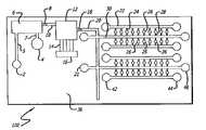
- FIG. 18is another exemplary embodiment of channels for multiple sample testing according to the teachings of the invention.
- the present inventionrelates to an apparatus comprising a substrate having at least one assay station in which the at least one assay station has at least a first assay station channel and in particular embodiments may have at least a second assay station channel.
- the term assay stationdescribes the area at which a particular assay takes place.
- an assay stationcomprises an area bounded by isolation medium, for example.
- the said first and second assay station channelseach separately are in communication with said at least one assay station.
- An arrangement of at least first and second multi-purpose channelsare provided which are in fluid communication with said assay station.
- the first multi-purpose channel and first assay station channelhave internal surface characteristics conducive to conduction of a sample solution therethrough.
- the channelsmay be either hydrophilic or are treated so as to be hydrophilic.
- shape of particular channelsprovides particular conducive or non-conducive characteristics to particular channels, particularly when channels having different relative geometric characteristics are in communication.
- At least one sample fluid inletis in communication with the at least first multi-purpose channel, and at least one isolation-medium inlet is in communication with the at least first and second multi-purpose channels.
- the at least one second multi-purpose channelhas at least an internal surface portion non-conducive to conduction of said sample solution. For example, if the sample fluid is aqueous, the second multipurpose channel inner surface would be hydrophobic or would be treated so as to be hydrophobic.
- the apparatuscan further comprise a sealing layer which seals at least one assay station. If desired the sealing layer can seal only the at least one assay stations or can seal portions of the apparatus substrate up to and including the entire substrate surface.
- the internal surface of said first multi-purpose channelpermits flowthrough of at least one of a sample fluid, air and an isolation-medium and the internal surface of said second multi-purpose channel permits the flowthrough of at least one of air or an isolation-medium but is not conducive to flowthrough the sample fluid.
- the internal surface of the multi-purpose channel and/or a surface of the second assay station channel immediately adjacent to the intersection of the second assay station channel and the second multi-purpose channelare both non-conducive to conduction of said sample fluid. This embodiment further assists in the localization of sample fluid to the assay station as well as the sealing and isolation of the assay station.
- the substratecan be configured such that at least first and second multi-purpose channels are in communication with a plurality of assay stations via the first and second assay station channels, respectively, of said plurality of assay stations.
- the plurality of assay stationsare arranged to provide at least one of simultaneous or sequential filling of the plurality of assay stations with the sample fluid solution conducted thereto via the at least first multi-purpose channels and the first assay station channels. Additionally, the plurality of assay stations can be arranged to provide at least one of simultaneous or sequential filling of the first and second multi-purpose channels with the isolation medium to seal the plurality of assay stations.
- the assay stationscan have disposed therein at least one reaction assay component.
- the reaction assay componentcan be one or more primers and/or a probe.
- a sample fluid inletcan be in communication with a sample fluid preparation area and the substrate can include at least one of a sample preparation chamber which may or may not have a lid. At least one element for controlling fluid flow in at least one of said channels can be incorporated into the apparatus or substrate.
- the flow of sample fluid in the channels on the substratecan be facilitated by the introduction of a flow-promoting fluid in to the sample fluid via a chamber for introduction of flow-promoting fluid.
- the chambercan be in communication with a chamber for mixing said flow-promoting fluid with the sample solution.
- the present inventionfurther comprise a method for conducting reactions on the substrates of this invention.
- An exemplary methodincludes introducing a sample fluid to at least one sample inlet; filling the at least one assay station and the second assay station channel via the at least one multi-purpose channel; allowing isolation-medium from the at least one isolation medium inlet to flow into at least the first multi-purpose channel; and running at least one reaction at said at least one assay station.
- the reaction in the assay stationprovides at least one of qualitative or quantitative data, for example, a colormetric result.
- the at least one of qualitative or quantitative datacan be obtained utilizing fluorecence which can be provided by at least one of intercalation of a flurophore or fluorecently labeled probe.
- the assay stations in the substratecan be irradicated with at least one excitation frequency.
- the probecan be labeled by at least one of a flurophore, an enzyme or component of a binding complex.
- the result of this methodprovides at least one of qualitative or quantitative data relating to the sample fluid being assayed.
- Exemplary qualitative or quantitativemay be exemplarily provided by florescence resonance energy transfer, luminescence or colorimetric change, for example.
- the reactions conducted on the substratecan be conducted under temperature control, for example, thermocycling conditions.
- the test samplecan be provided to the apparatus by initially subjecting the test sample to at least one preparative operation.
- the preparative operationcan be performed separately from said substrate or can be performed at at least one preparative station which is upon or within the substrate.
- the at least one preparative operationcan, for example, provide nucleic acids susceptible for use in the reactions to be conducted in the assay stations on the substrate.
- At least one assay reaction componentcan be disposed or placed into the at least one assay stations.
- the reactionsmay provide for the detection of a variation in nucleic acid sequence that is associated with virulence, disease, a particular phenotype or interindividual or interspecific variations or differences.
- variations in nucleic acid sequencesinclude single nucleotide polymorphisms (SNPs), tandem repeats and insertions and/or deletions.
- the at least one reaction which can be conductedincludes a nucleic acid amplification step, and the assay reaction component might in that case include a primer or primers.
- the method of the inventionprovides for sealing or isolation of the assays stations by displacement of sample fluid in the multi-purpose channels by an isolation-medium.
- the isolation-mediumcan be introduced sequentially into the at least first and second multi-purpose channels or isolation medium can be first introduced into the at least first multipurpose channel followed by introduction into the at least second multipurpose channel.
- the isolation-mediumis typically a material which is of an opposite nature as compared to the sample fluid, that is, substantially immiscible with the sample fluid.
- isolation mediumprovides the purging of air from said at least second multipurpose channel and the purging of said sample fluid from said at least first multipurpose channel, resulting in the isolation of said at least one assay station containing said sample isolation.
- the instant methodincludes a step of at least one of solidifying, curing and polymerizing said isolation medium.
- a particular but not limiting embodiment of the present inventionis directed to sample-preparation integrated, disposable, microfluidic devices and methods of using such devices.
- the devices and methods of the present inventionfacilitate analysis of nucleic acids, e.g. DNA, to rapidly detect and/or assess the risk of diseases in biological samples.
- the devices of the present inventioncan also be used for detecting amplified nucleic acid products for e.g. pharmacogenetic determinations such as for genetic fingerprinting.
- the term “detect” or “detection” or “detecting”means to diagnose or indicate that a subject test sample contains at least one disease-associated nucleic acid.
- deviceis meant a chip which incorporates elements necessary to transport nucleic acids and perform nucleic acid amplification, such as polymerase chain reaction (PCR).
- the devicecan optionally incorporate elements necessary for on-chip isolation of nucleic acids, such as a micro-filter, sized to trap white blood cells from a human blood sample, for example.
- DNA moleculescan be rapidly analyzed from a test sample, e.g. a biological sample.
- the test sampleis assayed to determine the presence or absence of a disease or assess the risk for developing a disease.
- a “test sample” employed by the present inventionincludes animal tissue and blood. The test sample is preferably whole blood.
- tissue homogenate or blood sample from a subjectis tested in the assay system of the invention.
- the tissue sampleis conventionally homogenized, digested and filtered to remove solid debris and obtain DNA in a solution which can be applied to the device of the invention.
- infectious pathogensviruses, bacteria, fungi, protozoans, microbial organisms or the like
- cancerous tumorscan be detected by providing a virus-specific primer or cDNA or fragment, pre-labeled with a fluorescent molecule such as fluorescein.
- the test sample DNAis conducted through the device to the primer where a fluorescent signal will be produced if the test sample contains the disease-causing virus, following PCR.
- Biological test samples in accordance with the present inventionare derived from subjects using well-known techniques such as venipuncture or tissue biopsy. Where the biological test sample is derived from non-human animals, such as livestock, blood and tissue samples are generally obtainable from livestock processing plants. Depending upon the particular embodiment being practiced, the test compounds are provided, e.g. injected, or optionally free in solution. Animals contemplated by the present invention include, for example, humans, reptiles, livestock, avian species, and domesticated pets such as dogs and cats. A preferred animal is a human being.
- the deviceis a lab-on-a-chip which can have various channel dimensions (i.e. lengths, widths, heights, diameters).
- the multipurpose channelsmay have lengths of about 1 mm to about 500 mm in length, from about 2 mm to about 10 mm in width, from about 0.5 mm to about 10 mm in thickness.
- the assay station channelsmay have similar dimensions and have exemplary lengths of about 0.01 mm to about 50 mm.
- a sample preparation areamay be about 5 to about 100 mm in length and width and about 0.5 mm to about 10 mm in height.
- the devicecan contain one or more sample introduction inlets, one or more chambers, one or more interconnected channels (sized to accommodate fluid flow) with surface of entire channels or a part of channels being selectively either inherently hydrophobic or hydrophilic or can be treated with hydrophobic or hydrophilic materials, and one or more assay stations for nucleic acid (e.g., DNA and RNA) amplification.
- the devicealso preferably contains at least one nucleic acid-adsorbant surface, such as a silica-derivitized surface.
- the devicemay alternatively contain at least one membrane filter for separating white blood cells from a test sample.
- the methods of the present inventionare carried out on the device following extraction of a biological test sample for substantially immediate detection results.
- resultscan be obtained in about 5 minutes to 2 about hours.
- the present inventionalso contemplates sample pre-processing off-chip and storage of the test sample, if processing is desired at a later time. Pre-processing is generally employed when the test sample is obtained from flow cell sorting devices or centrifugation devices, and the like. Sample preparation protocols for DNA or RNA can be found in Sambrook et. al., Molecular Cloning, A Laboratory Manual, 2nd edition. and/or be accomplished with kits from Qiagen, Whatman, etc., which utilize columns/membrane to bind DNA.
- pre-processingFor pre-processing, non-nucleic acid molecules that may inhibit subsequent amplification or interfere with the fluorescent analysis of products are removed. Pre-processing is conventionally performed in a device which can be modular and separate from the device of the present invention.
- the pre-processing module contemplated to mate with and/or fluidically attach to the device of the present inventionis a stand alone module.
- the stand alone moduleis linked by a liquid delivery tube which can connect to sample inlet 2 of the device of the present invention.
- pre-processingis performed on-chip.
- DNA and/or RNAis separated from other biological macromolecules and small molecules in crude samples such as body fluids (including blood, feces, sputum, aspirates, swabs), homogenized tissues samples (hair, mouth swabs, biopsies, aspirates, whole organisms), environmental samples (surface swabs, food, water/liquids) and the like.
- body fluidsincluding blood, feces, sputum, aspirates, swabs
- homogenized tissues sampleshair, mouth swabs, biopsies, aspirates, whole organisms
- environmental samplessurface swabs, food, water/liquids
- the present inventioncontemplates enriched or semi-purified populations of: white cells after buffy coat centrifugation separation; cells cultured in vitro and cells obtained after flow sorting.
- Preprocessingis performed off-chip to disintegrate large pieces by the standard procedure of aspirating the solid sample through a fine-bore needle such as a 21G-28G sized needle, for example.
- the samplecan be stored in standard chemicals, such as guanidium isothiocyanate, for example, to inhibit the degradation of DNA or RNA if sample processing cannot take place immediately.
- DNA and/or RNAis isolated from a test sample.
- the DNA and/or RNAis adsorbed onto a derivitized silica surface immobilized on the microdevice in the presence of appropriate buffers such as guanidium isothiocyanate and NH 4 Cl dissolved in water and Tris-HCl adjusted to pH 7.2, for example.
- the nucleic acidsadhere to the surface due to electrostatic charges.
- the adsorbent surfaces contemplated by the present inventioninclude: particle beads (glass beads) held in chambers with filters; paramagnetic particles immobilized in chambers by magnetic fields; and membranes or filters allowing liquids to pass through based on ionic charge properties.
- Immobilized or trapped nucleic acidsare conventionally washed to remove unwanted cellular debris and macromolecules.
- the DNA/RNAis then eluted by changing the charge of surface and/or nucleic acid using buffer of neutral pH (including water), either by forward-flow or by back-flushing.
- the fluidics of sample introduction, washing and elutionare carried out using passive or active valves and pumps, negative pressure suction or positive pressure.
- test samplesare introduced into the device using one or more pumps, such as syringe pumps, manual syringes, peristaltic pumps or vacuum pumps.
- nucleic acidsare amplified at assay stations.
- a digital camera having a sensing element and suitable optics for acquiring imagescan be employed to detect light of specific wavelengths emitted from the samples in the wells.
- Nucleic acidsare selectively amplified to sufficient quantities for direct and simultaneous detection without or with minimal post-amplification steps.
- Amplification reactions contemplated by the present inventioninclude, for example, polymerase chain reaction, ligase chain reaction or isothermal amplification reactions.
- a reverse-transcription step(employing enzymes capable of reverse transcription) for amplifying RNA targets is conducted before the main amplification step.
- a reverse transcription stepis combined with the DNA amplification step.
- nucleic acidsare introduced into the assay stations together with conventional reagents for the amplification reaction such as enzymes, primers, deoxyribonucleotide triphosphates dNTPs, fluorescent dyes, detergents, salts and buffers.
- reagents for the amplification reactionsuch as enzymes, primers, deoxyribonucleotide triphosphates dNTPs, fluorescent dyes, detergents, salts and buffers.
- some of the reagentsmay be pre-applied to the assay station and dried; these reagents will be solubilized on contact with the incoming sample/reagent liquid mix.
- a second liquid in characteristic, immiscible phasesuch as Mineral oil, wax, and the like, can be added to the chip through one or more channels after the sample/reagent mixture. The immiscible liquid will “seal off” fluidic access to the assay stations and act as a physical barrier to prevent the unwanted mixing of the contents of the assay station with that of adjacent as
- the assay stations on the device of the present inventioncan be arrayed in high density, either in two-dimensions or in three-dimensions, with each having an exemplary volume ranging from about 1 pico liter to about 50 micro liters.
- the present inventionhas the capacity to simultaneously amplify and detect nucleic acids present in about 10 to about 50,000 assay stations.
- the present inventionalso contemplates the inclusion of individualized thermal controls for each assay stations.
- the assay stationsare subjected to common thermal parameters. Common thermal parameters permit the reactions in each assay station to be optimized to a single set of thermal conditions by varying the design of the amplification reaction, or the concentrations of the reagents.
- the amplification reactionmay take place either by cycling through a set of predetermined temperatures for example, 95° C. for denaturation, 50-60° C. for primer annealing, with or without a 72° C. extension step.
- the amplification reactionis conducted isothermally at a constant temperature (e.g. 60° C.).
- the products of DNA amplificationare detected in situ homogeneously by detecting fluorescence emitted specifically in the presence of amplified DNA product. Detection is achieved using a fluorophore that specifically fluoresces on binding with double-strand DNA such as ethidium bromide or SYBR Green I, for example.
- a specific DNA sequencecan be detected using one or two fluorophore-labeled oligonucleotide probes using transfer of fluorescent resonance energy.
- the detection stepcan be performed after the complete amplification process.
- the detection stepcan be performed after individual thermal cycles.
- the detection stepcan be performed during intermediate points of an isothermal reaction.
- the detection of amplified nucleic acidsis performed with a digital camera using excitation from an off-chip source of incident UW or other appropriate wavelength light, and off-chip detectors for the emitted wavelength.
- the results of detecting amplified DNA productsare used in comparison against a pre-amplification baseline which is experimentally determined by the fluorescent emission reading within the experiment obtained at amplification cycle zero.
- the pre-amplification baselineis determined with respect to different fluorescent probes at the same assay station, or with probes from the reactions of different assay stations.
- the lab-on-a-chip devicecontains all the integrated elements required for detecting the presence of e.g., viral or bacterial DNA in a biological sample and assessing the risk of disease.
- the present inventionthus contemplates that both quantitative and qualitative measurements of DNA can be used to assess the subject's risk of having a disease or condition. For example, the presence of a Bacillus anthracis DNA in a test sample indicates the subject has been exposed to the bacterium which causes anthrax and may be at risk for having the disease associated therewith. Conversely, the absence of Bacillus anthracis DNA in a test sample indicates that the subject does not have the disease associated therewith.
- infectious bacterial or viral diseasescan be rapidly detected in a test sample in accordance with the present invention.
- diseases detectable in accordance with the present inventioninclude, but are not limited to: anthrax, small pox, Legionnaire's disease, AIDS, Hepatitis A, B, and C, tuberculosis plague, and malaria.
- the present inventionpermits the detection of cancer, leukemia, thalassemia, asthma, allergies, strep or sore throat, food poisoning, near-sightedness in children and adults, Nipah and sexually transmitted diseases.
- the present inventionalso permits the detection of pharmaceuticals in a test sample.
- This aspect of the present inventioncan be used for e.g. rapid drug screening or for determining the presence of a drug in a particular tissue, for drug efficacy assessments, for example.
- Still another aspect of the present inventionprovides for the detection of genetically-modified food and for genetic fingerprinting.
- the chipwill detect the artificially introduced genes in the food by PCR.
- the chipwill analyze DNA sequence variation between individual (human, plants, and animals) by PCR.
- the chip apparatus and fluidic networkcan be manufactured at the micro scale level by existing microfabrication techniques such as glass etching, plastic hot embossing, plastic injection molding, resin casting, laser ablation, stereolithography photolithography, LIGA processes, CNC machining photocuring or metal forming techniques to form a chip with open structures such as open channels and assay stations.
- the open channels and assay stationscan then sealed and closed with cover film or plate.
- the dimensions of the channelscan range typically from 1 micro meter to 10 mm. Therefore, microfabrication is only an option, not the exclusive means by which to produce the chip 100 .
- Other more common technologiessuch as computer numerically controlled (CNC) machining, metal forming, plastic injection molding, or hot embossing can also be used for fabrication.
- CNCcomputer numerically controlled
- exemplary microstructures of a chip apparatus 100 having a sample fluid preparatory area shown as constructed on substrate 36can be made of a suitable material such as glass, plastic, an elastomer such as poly-dimethylsiloxane (PDMS), metal, ceramic or a composite.
- PDMSpoly-dimethylsiloxane
- substrate 36can be made of a suitable material such as glass, plastic, an elastomer such as poly-dimethylsiloxane (PDMS), metal, ceramic or a composite.
- PDMSpoly-dimethylsiloxane
- various standard glass chemical etching techniquescan be used on a glass substrate.
- LIGA processestypically comprise synchrotron radiation in a resist structure, such as polymethylmethacrylate (PMMA), and exposing the structure and chemically developing the structure to provide a micro mold based upon pattern of the resist structure.
- Metallic powder fillingmay be utilized in order to provide for improved conduction of heat, for example, when substrate 36 is comprised of plastic.
- a replication(a type of elastomer casting on a solid microstructured die) and molding techniques can be used. Additionally, silicon and silicon-based compounds may be utilized to provide substrate 36 . Then substrate 36 may be sealed with the sealing layer 40 (not shown in top view). If sealed, various configurations of sealing may be provided, such as sealing a portion of the assay stations 26 only, or sealing assay stations 26 in combination with assay station channels 24 , 28 and/or first and/or second multipurpose channel 30 and 22 , respectively.
- the sealing layeris normally a plastic film that seals the channels and assay station or plurality of assay stations, except chamber 6 and all the inlets and outlets, by a bonding process including, but limited to, thermal bonding, electrostatic bonding, adhesive bonding.
- the sealing layer 40can also consist of other materials such as glass plate or plastic plate or an elastomer like polydimethylsiloxane (PDMS).
- the sealing layer 40may also be comprised of a selfhealing/sealing type of material such as rubbers, elastomers, gels and/or a valve/lid which may be opened via mechanical, and/or electrical, and/or magnetic, and/or chemical means that would allow for introduction of a syringe, for example, into covered assay station 26 , to provide for the application of a particular assay reaction component, for example, into assay station 26 .
- a self-healing/sealing type of materialmay not be utilized.
- Fabrication of the assay stations or portions thereof and the various channelsneed not be restricted to only one of either substrate 36 or sealing layer 40 .
- a portion of assay station structurescan be formed on the substrate 36 or sealing layer 40 , and a portion of channel structure can be made on the sealing layer or substrate.
- the particular portions of various elements provided upon/in the substrate 36 and sealing layer 40are brought together in proper alignment to provide the complete channel or other structure.
- Embodiments of the apparatus 100may include at least one flow controlling element.
- Flow controlling elementsinclude various valves, gates and restrictions that may be provided at virtually any part of the apparatus, including channels as well as points of communication, for example, according to a user's desire or need for regulating/controlling fluid flow.
- Assay station 26may comprise at least one component of any number or type/class of assay reaction, the at least one component including, but not limited to, nucleic acids, probes, primers, antibodies, cells, assaying salts, catalysts, reporters, quenchers, enzymes, proteins, peptides, drugs, small molecules and fluorophores, for example. Additional examples include a synthetic molecule(s) from a combinatorial library of molecules, a peptide library a nucleic acid library or aptamer library.
- the at least one component of the assay reactionmay be disposed into at least one assay station 26 via a carrier.
- a short list of carriersincludes, but is not limited to, aqueous solutions, solvents and gels.
- Air and/or a gasmay also be considered as a carrier for the deposition of at least one component into said at least one assay station 26 (spray or ink jet deposition, for example).
- the particular carrier or carriers so utilizedmay be adapted to be driven off by evaporation, for example.
- Other methods to drive off a carrier, such as ovens, lamps, lasers, force air, etc.,are well known to those in the art.
- the at least one component, such as probes and/or cells for examplemay be bound to the internal surface of assay station 26 by covalent bonds and/or absorption.
- a nucleic acid fragment to be amplified and/or primer or primersmay be deposited into each assay station 26 on the substrate 36 manually or by a liquid dispensing robot.
- the assay station 26is then dried to drive off the carrier of the reaction component before adding the sealing layer 40 .
- the sealing layermay be added before the drying of assay station 26 and in some embodiments the station may not need to be dry.
- Other embodimentsmay have the sealing layer 40 added during the running of the assay.
- the probes/primersmay be added after assay station 26 is filled with sample fluid 56 .
- the nucleic acid fragment to be amplifiedincludes, but is not limited to DNA or RNA fragments, cDNA, nucleic acid primers and/or probes conventionally obtained by the skilled artisan using standard methods.
- a DNA fragment useful in accordance with the inventioncan be pre-fabricated in a commercial DNA synthesizer.
- the assay stationsmay be air dried in accordance with the teachings of the present invention. Drying may be carried out at room temperature at ambient atmospheric pressure. Depending upon the number of assay stations, drying may take from about 10 minutes to about 5 hours. Preferably, the assay stations are dried in about two hours.
- both the substrate 36 and the sealing layer 40have hydrophilic surfaces to enhance the liquid flow by capillary force.
- a typical hydrophilic substrate 36is glass.
- a normally hydrophobic substancesuch as a plastic can be treated to transform the substance into a hydrophilic substance by treating the plastic with diluted hydrofluoric acid or sulfuric acid.
- Another way to alter the surface properties of a hydrophobic substance, contemplated by the invention,is by adding a hydrophilic polymer solution, or by adding a surfactant to the hydrophobic substance, e.g., plastic.
- those of skill in the artare familiar with many various methods for treating/modifying surfaces, particularly surfaces that are to be utilized for microfluidic applications, such as plasma treatments or coatings, for example.
- glasswhich is typically characterized as having hydrophilic surfaces, may be treated so that the surface or portions of its surface has instead hydrophobic characteristics.
- Such treatmentsmay be utilized to provide apparatus and/or portions of the apparatus 100 having particular characteristics (such as wetting characteristics, for example) in accordance with the teachings of the present invention, in order to provide an apparatus configured according to a particular user's preference.
- the surfaces of the various channels and stationsmay have various portions (i.e. substrate, sealing layer) having either wholly, differentially or in any combination, treated surfaces in order to provide a desired arrangement of surface characteristics.
- Channels such as 22 , 20 and 30 in FIG. 1 for examplemay be chemically etched by hydrofluoric (HF) acid on a glass slide for example, after patterning by photolithography using designed masks having desired patterns.
- HFhydrofluoric
- etched slidesare immersed into a freshly prepared mixture of about 70% sulfuric acid and about 30% aqueous solution of hydrogen peroxide (about 30% H 2 O 2 ) at about 100° C. for about 10 min.
- the slidesare then rinsed thoroughly by running tap water over them several times followed by deionised water, respectively.
- the slideis checked for total wetting achieved on every part of the slide, for example, and that there are no remaining hydrophobic patches.
- a portion or portions of the slidemay not be treated if a user desires not to alter the surface characteristics at those area/areas.
- hydrophilic glass surfacesare obtained.
- hydrophilic materialscan be used to treat the plastic surfaces.
- the hydrophilic materialsinclude poly(ethylene imine) (PEI), poly(vinyl alcohol), polyacrylate etc as known in the art.
- Precursor moleculesare prepared freshly at the ratio of about 10% concentration in a suitable solvent, e.g. Hexane, Hexadecane etc.
- Test sample inlet 2 for test sample(e.g. whole blood) is connected typically perpendicular to the upper surface of substrate 36 such that test sample inlet 2 is fluidically coupled to sample preparation chamber 6 through channel 5 .
- Buffer inlet 4is also connected typically perpendicular to the upper surface of substrate 36 , and such that buffer inlet 4 is fluidically coupled to sample preparation chamber 6 through channel 7 .
- Sample preparation chamber 6is sealed at least partially on its lower surface by sintered glass block 31 , to which absorbent 5 and/or a vacuum suction means such as a vacuum pump is applied to extract a mixture of e.g. whole blood sample, lysing buffer and washing buffer through the sintered glass block 31 .
- the block of sintered glass powder 31which is inserted into sample preparation chamber 6 , is also called porous glass.
- the typical size of a poreranges from about 1 micro meter to about 500 micro meter.
- the sintered glass block 31occupies the lower portion of the sample preparation chamber 6 and typically is rigidly fixed inside the chamber 6 by a slight size difference; that is, the size of the glass block 31 is slightly larger than the size of the sample preparation chamber 6 .
- An adhesive substancecan also be used to fix the glass block 31 inside the sample preparation chamber 6 .
- a vacuum, or liquid absorption by the absorbent 5is created underneath the glass block 31 thereby extracting the sample, washing buffer and lysing buffer through the glass block 31 .
- Elution bufferis injected into sample preparation chamber 6 .
- Elution bufferpenetrates into the glass block 31 and releases the DNA molecules from the surface of the glass block 31 .
- the DNA moleculesdiffuse (or by flow circulation) into the elution buffer contained in sample preparation chamber 6 . So, therefore, the elution buffer contains DNA molecules at this time.
- other chemicals required to perform the subsequent PCR reaction and fluorescent detection of the PCR productcan be added to the elution buffer at this time.
- the cellsare lysed utilizing heat.
- the cellsmay be heated to a lysing temperature either when still in sample preparation chamber 6 or may be conducted into the assay stations and lysed there.
- a miniature heater and temperature sensormay be embedded into each assay station 26 in order to perform individual thermal cycling at each assay chamber 26 .
- heatmay be also utilized to evaporate an amount of elution buffer in order to increase the concentration of a solute, for example DNA, in a sample fluid.
- This evaporative stepmay be conducted at the sample preparation area 78 or at individual assay stations 26 , for example, wherein the sealing layer 40 , may be gas permeable but not liquid permeable, for example.
- various electrochemical sensors and electrical and electronic sensorsmay be embedded into each assay station 26 .
- a useris provided electrochemical-based detection/data as a result of assays run within said assay station.
- the datamay be in the form of changes of electrical conductance, resistance and other indicators typical to experiments utilizing electrochemical detection, as known to those in the art.
- the apparatus and methods provided by the present inventionare useful for a number of various assays/reactions.
- all of the required enzymes, fluorescent dye, deoxyribonucleotide triphosphates dNTPs, detergents, and other chemicals and bufferscan be added into sample preparation chamber 6 through buffer inlet 4 .
- vibrating actuator 34can be applied to oscillate, typically vertically, to press diaphragm 48 , thereby agitating the elution buffer in the sample preparation chamber 6 to allow more DNA molecules to leave the glass block 31 and enter the elution buffer which occupies sample preparation chamber 6 .
- a fluidfor example a gas or an oil
- a fluidmay be injected into sample preparation chamber 6 through either through test sample inlet 2 exclusively with buffer inlet 4 closed, or alternatively through test sample inlet 2 with buffer inlet 4 remaining open to act as vent until it is filled with elution buffer.
- the fluidpurges the elution buffer containing the released DNA molecules, and causes exemplary flow controlling element, hydrophobic valve 8 , to open, permitting elution buffer to enter into initially empty chamber for mixing sample solution and flow promoting fluid, where the elution buffer fills chamber 12 .
- the valve 8can also be a valve type that is operated by various other means such as mechanical, electrical, pneumatic or magnetic.
- the elution bufferis prevented from exiting the chamber 12 by hydrophobic valve 18 that is located at the entrance to main liquid distribution channel 20 .
- Providing fluidcan be achieved again through conventional techniques such as pressurization.
- chamber 12Before the buffer in chamber 12 flows out to assay stations, chamber 12 can also be used for the following purposes: (1) to meter the buffer flowing out of chamber 12 (that is, to control the volume of buffer flowing out of chamber 12 by proper choice of volume of chamber 12 ); (2) to retain buffer for period of time to let the DNA distribution homogenize before the buffer flows out of chamber 12 ; and (3) to increase DNA concentration, as mentioned previously, in the chamber 12 by evaporating a portion of the water in buffer. The resulting higher concentration of DNA in buffer flowing to assay stations 26 increases the DNA detection sensitivity and specificity.
- chamber 16is provided for the introduction of flow promoting fluid (FPF), released through diffusion channels 14 to chamber 12 .
- Suitable flow promoting chemicalsinclude, but are not limited to, heparin, sodium dodecyl sulfate (SDS), cetyltrimethyl bromide (CTAB), Triton-X, Tween 20, NP-40 and any other surfactant that does not inhibit subsequent DNA amplification and detection chemistry, and does not fluoresce under detection light excitation.
- one or more main sample fluid channel 20is fluidically coupled to at least one first multi-purpose channel 30 which is in communication with at least one first assay station channel 28 , and at least one assay station 26 .
- first multi-purpose channel 30which is in communication with at least one first assay station channel 28 , and at least one assay station 26 .
- the flowis caused by capillary pressure generated by surface tension which moves the liquid forward.
- Such surface tensionis generated at the contact region between the sample fluid and the solid surface of the chip (that is, the surface of channels 20 , 30 , 28 , and assay stations 26 ). With the addition of the FPF, the surface tension is lowered enough to cause the sample fluid to flow through valve 18 and move further into all other channels and assay stations.
- the air volumes in channels 20 , 30 , 28 and assay stations 26are at least purged by sample fluid through at least one second assay channel 24 , which are fluidically coupled to the assay stations 26 and second multi-purpose channels 22 , so that channels 20 , 30 , 28 and assay stations 26 become filled with the sample fluid.
- the volume capacity of chamber 12is designed to be at least equal to or greater than the combined volume of the channels 20 , 30 , 28 and assay stations 26 .
- Valvescan be installed inside the second assay channel 24 .
- Such valvescan be actuated by actuating means such as mechanical, pneumatic or electromagnetic;
- a porous materialcan be installed inside at least one second assay channel 24 to block the flow of sample fluid but allow air to vent into second multi-purpose channel 22 ;
- a layer of hydrophobic materialmay coat at least a portion of the second assay channel 24 to block the flow of sample fluid but allow air to vent into second multi-purpose channel 22 ;
- the hydrophobic materialtypically can include, but is not limited to, poly (styrene-butadiene-styrene) (SBS), poly(methyl methyacrylate) (PMMA), polycarbonate, polyimide, polypropylene, OTS, fluorochemical acrylate polymer (such as EGC-1700 made by 3M) or epoxy resin.
- SBScan be dissolved in an organic solvent to form a solution, which can be cast onto a glass or plastic surface to obtain a very thin film by drying.
- Epoxy resincan be directly dropped onto glass or plastic surfaces to form a thin film by ultra-violet (UV) curing or heating;
- the hydrophobic materialcoats at least one second multi-purpose channel 22 so that the sample fluid can occupy second assay channel 24 but cannot enter into second multi-purpose channel 22 while air can be purged into second multi-purpose channel 22 .
- the width/diameter of second multipurpose channel 22is provided to be larger that the width/diameter of second assay channel 24 as depicted in exemplary FIG. 17 , which depicts a side cross-sectional view of an example of this type of configuration.
- a drastic enlargement, which may be sharply made, at approximately the end of assay channel 24is effective to stop the flow of sample fluid 56 and prevent it from entering second multipurpose channel 22 .
- Line depicted between the various channelsare only for illustrative purposes, to show graphically the various channels and their spatial relationships in the exemplified figure.
- OTSoctadecyltrichlorosilane
- a suitable solvente.g. Hexane, Hexadecane etc.
- the solutionis then brushed or sprayed into the certain assigned regions for curing for about 15-20 min at room temperature, for example. In this way, hydrophobic surfaces are obtained.
- fluorochemical acrylate polymersuch as EGC-1700 made by 3M
- the coating solutionis prepared freshly with about 1.5% acetic acid and the finished coated slides are preferably cured in an oven, for example, at about 80 to about 100° C. for about 30 min.
- Digital camera 32detects when all the assay stations 26 are filled by sample fluid.
- the digital cameramay be a camera with a charge-coupled device (CCD) sensing element and all possible types of suitable optics for acquiring images.
- An optical filteris positioned in front of the sensing element of the camera, so that only light of specific wavelengths emitted from the liquid in assay stations 26 is allowed to pass through the filter and reach the sensing element (to be detected by the camera).
- isolation medium 54may be introduced through selected combinations of inlets 42 , 44 , 46 , and 21 , for example, which are fluidically coupled to first and second multi-purpose channel 30 and 22 respectively, for example, by any of the following non-comprehensive list of means: electro-osmosis pumping, positive pressurization (such as injection with a syringe), capillary flow, electrowetting, thermocapillary flow and/or vacuum suction.
- isolation mediummay be deposited by casting and/or robotic dispensing, for example, which would purge sample fluid 56 from the first multipurpose channel 30 .
- Filling channels 30 and 22 with isolation mediumcan be executed sequentially or simultaneously, and is typically performed by the introduction of isolation medium through inlets that first purge sample fluid from the first multi-purpose channel and then subsequently isolation medium is introduced into the second multi-purpose channel to purge air therefrom.
- the isolation medium 54fully fills first and second multi-purpose channels 30 and 22 .
- the isolation medium 54is selected so as to be impermeable to the elution buffer, i.e. the buffer cannot diffuse into medium 54 .
- the isolation medium 54typically can be wax, heat cured wax, oil, phase-changing plastics, thermally curable polymer liquid, cyanoacrylate and its derivatives, two-part epoxies or ultra-violet (UV) or visible light curable polymer liquid and hot-melt materials (such as those typically utilized in glue guns, for example).
- isolation mediums 54include, but are not limited to, thermally cured polymer, such as polydimethylsiloxane (PDMS) elastomer, as well as other silicone elastomer and liquid silicone precursors. Curing activation temperatures may be higher than about 40 degrees C.
- PDMSpolydimethylsiloxane
- Exemplary ultra-violet (UV) curable isolation medium 54such as polyacrylate and its derivatives, polyurethane precursors and its derivatives may also be utilized.
- the UV or other appropriate radiation sourcesinclude a UV lamp that is focused onto multipurpose channel 22 and/or 30 , for example, by a lens or lenses, a UV lamp illuminating onto multipurpose channel 22 and/or 30 areas that remain exposed after application of a mask having appropriate cut-out portions which provide multipurpose channel 22 and/or 30 areas exposed to UV, for example.
- a localized irradiation sourcethat may be directed onto isolation-medium 54 containing multipurpose channels 22 and/or 30 may also include a localized UV source such as fiber optics.
- Additional exemplary isolation medium 54may also comprise any adhesive which solidifies as a result of solvent evaporation, for example.
- provisions, such as appropriate venting holes and/or slots, in sealing layer 40 and/or substratemay be provided.
- the venting holes and/or slotsmay be provided in sealing layer 40 areas that cover the multipurpose channels, for example.
- Isolation medium 54is preferably, substantially immiscible with water and/or aqueous fluid, including with water and/or aqueous fluid containing a surfactant. Isolation medium 54 may be non-transparent and/or fluoresce (not at a wavelength or intensity that may interfere with the assay) and have low viscosity.
- a solidifiable sealant 67for example, wax, hot melt adhesive liquid, polymer liquid, elastomers
- Other sealing structuressuch as caps, lids and valves, can also be utilized to seal off air-liquid interfaces and it is preferable that solidifiable sealant 67 and the caps, lids, and valves can endure temperatures up to and around 100° C.
- the sealant 67 and/or the other sealing structuresform a fixed volume of liquid/fluid in the assay stations and suppresses the generation of vapor and during PCR, for example, and any other ration that takes place at elevated temperatures.
- the solidifiable sealant 67may be deposited via robotic, manual and other dispensing means, as known in the microfluidic arts.
- the multipurpose channelsmay have, instead of oil/wax-like-type isolation medium 54 , ambient air or saturated humid air, or any other humidity saturated vapor, introduced and disposed therein after conduction of sample fluid 56 into the assay stations, to minimize evaporation from assay stations.
- Ambient air or saturated humid air, or any other humidity saturated vapormay be utilized to purge sample fluid 56 from first multipurpose channel 30 .
- the chip 100may be subjected to pressure above atmospheric pressure when placed inside an enclosure 514 , such as a molecular analyzer, during analysis such that the evaporative temperature of sample fluid 56 is raised in order to minimize sample fluid evaporation from assays stations.
- an enclosure 514such as a molecular analyzer
- the DNA or other chemicals in the sample fluid contained in each assay station 26are isolated within the domain of the assay stations 26 and the first assay station channel 28 and second assay channel 24 so that the DNA or other chemicals do not diffuse to an adjacent assay station in the assay station array.
- the isolation property of the isolation medium 54is sustained at temperatures up to and around 100° C. Since the highest temperature for the PCR process is 95° C., no cross contamination occurs in the subsequent DNA amplification step.
- the injection of the isolation medium 54can be achieved through conventional techniques such as electro-osmosis, positive pressurization by injection, capillary flow electrowetting, thermocapillary flow or vacuum suction.
- a washing stepmay be added in order to wash away at least one undesired component of a reaction, such as non-specific binding of a labeled probe or other unwanted reaction components, for example, in assay stations 26 .
- Thismay be utilized in embodiments wherein a probe/marker molecules are utilized which are strongly bound to the internal surface of assay station 26 , for example, and also bind to the particular molecule (DNA, for example) that is of interest.
- a washing stepcomprised of introducing a washing buffer (via vacuum or pressure, for example) into the multipurpose channels and assay station and channels, is provided in order to wash away nonspecific components of the assay reaction.
- the markers/probes that are bound to assay chamber 26 surfacesremain behind and are then assayed for the presence or absence of the molecule of interest bound to the marker/probe.
- Each assay station 26may contain a fluorescent dye.
- Digital camera 32captures both white light and/or the fluorescent emission images from fluorescent dye.
- a sealing layer 40may be applied to the upper surfaces of all of the fluid compartments and channels 20 , 30 , 28 and assay stations 26 .
- the sealing layer 40should be bonded to the substrate 36 preferably before the test sample is added to the sample preparation chamber 6 .
- the sealing layer 40may not applied to sample preparation chamber 6 , and the mouths of the inlets 2 , 4 and 21 , 42 , 44 , 46 .
- the sealing layer 40can be omitted from the upper surface of channels 24 and/or 22 depending upon the particular assay protocol utilized and the temperatures associated therewith. Sealing layer 40 may in particular embodiments seal off the channels and assay stations from the environment, enhance the capillary flow, and enable the liquid flow by injection or vacuum.
- the sealing layer 40is normally a plastic film that seals the channels and assay stations, except sample preparation chamber 6 and all the introduction inlets, by a bonding process including, but limited to, thermal bonding, electrostatic bonding, mechanical jointing and adhesive bonding.
- the sealing layercan also be comprised of at least one of a glass plate, a plastic plate, a thermoplastic, an elastomer, a plastic film and a thermally activated adhesive. Additionally, sealing layer may be comprised of the same material as the substrate.
- sealing layer 40 and substrate 36are transparent to UV and other wavelengths, including those in the visible spectrum, and do not generate fluorescence that will interfere with experimental measurements/results.
- sealing layer 40may also be provided with holes/vents that are located at a variety of locations.
- at least one hole in the sealing layermay be provided at a location, or locations in the case of a plurality of holes, over the various areas, such as channels or waste reservoir 45 , for example.
- sealing layer 40may be comprised of a material that is gas permeable. This would allow venting fluids to escape, for example, while providing a barrier to the loss of a liquid fluid from the apparatus 100 , for example. If such a sealing layer is provided, venting holes may not be required to allow fluids and various mediums to flow through the various channels.
- the channels 20 , 30 , 28 , 24 and 22can range in width typically from about 1 micro meter to about 5 mm, while the channels can range in depth typically from about 1 micro meter to about 1 mm.
- the assay stations 26can range in width or diameter typically from about 1 micro meter to about 10 mm, and typically from about 1 micro meter to about 1 mm in depth.
- the surface wetting properties and dimensions of each type of channel 20 , 30 , 28 , 24 and 22can vary from the other types of channels. All of the structures can be manufactured using such processes as micro electromechanical systems (MEMS) technology, computer numerically controlled (CNC) machining, laser machining, electrical discharge machining (EDM), chemical etching, injection molding, hot embossing, or stamping.
- MEMSmicro electromechanical systems
- CNCcomputer numerically controlled
- EDMelectrical discharge machining
- Each assay station 26may subject to a thermal condition required for DNA amplification as previously discussed. Such thermal conditions include thermal cycling required for the polymerase chain reaction (PCR).
- PCRpolymerase chain reaction
- the FPFcan also be added through test sample inlet 2 or buffer inlet 4 to elution buffer in sample preparation chamber 6 to actuate the flow into the assay stations 26 .
- chamber 12channels 14 and chamber 16 .
- This chip designis shown in FIG. 3 and FIG. 4 .
- the valve 8assumes the function of valve 18 shown in FIG. 1 and FIG. 2 .
- the design of the chip 100 and the operating method of sample preparation and analysisis identical to that presented for FIG. 1 and FIG. 2 . Therefore, no additional discussion is presented.
- valve 8 and valve 18can be operated by any means, for example mechanical, electrical, magnetic, chemical or pneumatic.
- the apparatusmay not be provided with a sample preparation area wherein preparation of sample fluid is conducted “off-chip”. Exemplary configurations such as those depicted in FIGS. 5A-E may therefore be provided.
- substrate 36has at least one assay station 26 having in communication thereto a first assay channel 28 and a second assay channel 24 .
- isolation media inlet 42is provided in communication with second multipurpose channel 22 .
- exemplary sample solution inlet 21is also provided in communication with first multipurpose channel 30 .
- a reservoir 45is depicted in communication with first 30 and second 22 multipurpose channel.
- sealing layer 40may be provided over particular areas according to particular embodiments as described previously (not shown due to top view of FIGS. 5A-E ). Exemplary configurations include sealing layer 40 covering assay stations 26 only or in combination with one or both multipurpose channels, for example, depending upon the type of assay to be run and the characteristics of fluids that will be utilized in conjunction with substrate 36 .
- first assay channel 28has a smaller cross-sectional area than the second assay channel 24 , as shown in FIGS. 5A-E . This reduces the speed and/or flow of sample fluid 56 , that enters assay station 26 , thus allowing the air being displaced, via sample fluid 56 entry into assay chamber 26 , to be conducted through second assay chamber channel 24 and into second multipurpose channel 22 . This reduces the likelyhood that air pockets will form and be trapped within assay station 26 as sample fluid 56 flows into assay station 26 and eventually into assay station channel 24 .
- first assay station channel 28is depicted exemplarily herein as having a circular cross-sectional shape/profile, this channel may have any shape that provides flow restriction to minimize sample fluid 56 flow out into first multipurpose channel 30 .
- a portion 50 of second assay station channel 24 adjacent second multipurpose channel 22may be provided with surface characteristics that are non-conducive to the flow of sample solution 56 .
- second multipurpose channel 22may have or be treated to provide a hydrophobic surface.
- sample solution 56is an aqueous solution
- the sample solution 56will flow into assay station 26 via sample solution inlet 21
- first multi-purpose channel 30which in this example has hydrophilic surface characteristics.
- the surfaces of first assay channel 28 and assay station 26also have hydrophilic surfaces, for example.
- Sample solution 56flows to second multipurpose channel 22 and stops, due to second multipurpose channel's 22 hydrophobic surface characteristic or, as in particular embodiments as depicted in FIG. 17 , the abrupt expansion of channel diameter from second assay channel 24 to second multipurpose channel 22 .
- portion 50 of second assay channel 24may also have hydrophobic surface characteristics at which point sample fluid 56 flow would stop, shown in FIG. 5B , C, for example.
- reservoir 45may be provided with absorbent 5 .
- Absorbent 5may be comprised of at least any one of cellulose-based material or synthetic material, polyacrylamide gels, particles and porous materials.
- Reservoir 45may be sealed by sealing layer 40 or may be open to the atmosphere.
- vents 52may be provided so that fluid flow in the various channels may occur.
- reservoir 45 and absorbent 5are herein depicted as being of sufficient size to be in communication with a plurality of terminal portions of multipurpose channels, it is also contemplated that terminal portions of the multipurpose channels may be in communication with exclusive reservoirs and/or absorbent 5 not in communication with any other multipurpose channel.
- isolation medium 54is allowed to flow into first multipurpose conduit 30 .
- Isolation medium 54may be introduced via various methods and in accordance with various embodiments of the instant invention.
- isolation medium 54may be introduced into first multipurpose channel 30 via isolation medium inlet 21 .
- isolation medium inlet 21may serve a dual or multipurpose as sample fluid inlet 21 and as an inlet for isolation medium as shown in FIG. 5A .
- FIG. 5AIn other embodiments for example, as also seen in FIG.
- isolation medium 54may be introduced via an inlet 42 or inlets that do not serve a dual purpose but rather are inlets to second multipurpose channel 22 that is conducive to the flow of air and an isolation medium 54 .
- isolation medium 54not only serves to seal assay station 26 , for example, but also provides for the displacement of sample fluid 56 from first multipurpose channel 30 .
- the displaced sample fluid 56may flow to a reservoir 45 , as exemplified in FIG. 5A , which may or may not be sealed with sealing layer 40 and may or may not contain absorbent 5 .
- isolation fluid 54into the second multipurpose channel 22 , wherein the isolation fluid 54 displaces not sample fluid 56 , but air.
- the surface of second multi-purpose channel 22may be inherently or treated to be hydrophobic, for example, and thus acts to halt the flow of sample fluid at area 50 .
- isolation medium 54Upon introduction of isolation medium 54 into the second multipurpose channels, the air therein is displaced and thus assay station 26 , or pluralities thereof, are sealed by said isolation fluid 54 . This addresses the concern of evaporation and cross contamination of the contents of one assay station with others.
- isolation medium 54may be introduced to exemplary second multipurpose channel 22 .
- isolation medium 54is introduced via inlet 21 , flows and displaces sample fluid 56 from the first multipurpose channel into reservoir 45 . This results in the partial sealing of assay station 26 at the lower hand portion, as depicted. Isolation fluid may then flow into absorbent 5 and then come into communication with second multipurpose channel 22 , as indicated by the arrows, and flow into the second multipurpose channel 22 , displacing the air therein and sealing the upper hand portion of assay station 26 , resulting in the complete sealing of the assay station 26 or stations.
- inlet 42may act as a vent and not as a point of entry for the introduction of isolation fluid into second multipurpose channel 22 , for example, as shown in FIG. 5D .
- FIG. 5Ddepicts a detachable absorbent 5 component, that may be bought into communication with the multipurpose channels.
- the absorbent 5provides for the uptake of excess sample fluid 56 , and may also uptake excess isolation medium 54 .
- the application of absorbent 5may also provide to speed up the filling of assay station 26 or stations by providing another “pulling” force onto the columns of sample fluid 56 in the respective first multipurpose channel.
- isolation medium 54has been introduced via inlets 21 and 42 .
- FIG. 5Ethe assay stations have been sealed and the absorbent 5 removed, now having excess sample fluid contained therein.
- absorbent 5may also have absorbed therein isolation medium 54 .
- FIG. 18An exemplary configuration is depicted in FIG. 18 .
- a common second multipurpose channel 22is provided in communication with multiple assay stations.
- the plurality of assay stationsmay be in communication with a plurality of separate first multipurpose channels, for example as shown ( 30 and 30 ′), into which sample fluid 56 which may differ from one another, may be introduced. This provides for assaying/testing of multiple/different sample fluids on one apparatus.
- FIGS. 6A-Cdepict an alternative embodiment.
- assay station 26 or stationsare provided with a venting hole 66 formed in sealing layer 40 (not shown in FIG. 6A , a top view).
- FIG. 6Ba side view of exemplary FIG. 6A .
- assay station vent 66is shown open to the atmosphere.
- Supports 62are provided to support isolation medium platform 60 which is disposed over at least the assay station vent 66 and defines gap 64 .
- sample fluid 56is introduced into first multipurpose channel 30 and flows and fills assay station 26 via first assay channel 28 .
- sample fluid 56fills assay station 26 (or stations) as well as assay station vent 66 , as seen in FIG. 6B .
- isolation medium 54displaces sample fluid 56 in first multipurpose channel as before.
- isolation medium 54now is introduced to gap 64 .
- Isolation medium 54flows to fill in gap 64 defined by isolation medium platform 60 and sealing layer 40 , as shown in progress in FIG. 6C .
- FIG. 6Ddepicts this filling and sealing process from a cross sectional side view of FIG. 6C .
- FIG. 6Edepicts this exemplary embodiment at the point where the sample fluid in assay stations is sealed by isolation medium 54 .
- a solidifiable sealant 67may be deposited all around isolation medium platform 60 and into all outlets and inlets 21 , for example, in order to seal off and isolate all the fluidic paths (channels and inlets) from the atmosphere, as depicted in a side view in FIG. 6F .
- Thisthus forms a fixed volume (of sample fluid 56 and isolation medium 54 , for example)of liquid inside the chip 100 to suppress vapor generation during PCR and other reaction at elevated temperature.
- Sealant 67can be in form of wax, hot-melt compositions, adhesive liquid, polymer liquid and elastomer for example. Additionally, this solid sealant effect can also be achieved utilizing caps, lids and/or valves, in any preferred combination. It is preferred that solidifiable sealant 67 as well caps, lids and/or valves endure temperatures up to about 100° C.
- isolation medium platform 60is not utilized and assay station vent 66 has been moved to an exemplary position over assay station channel 24 .
- solidifiable sealant 67may be disposed directly onto sealing layer 40 (not shown in this top view) to cover assay station vent 66 as well as outlets and inlets 21 , in order to isolate all the fluidic paths and provide a fixed volume of fluid, as detailed above, from the atmosphere and thus minimized and/or eliminates mixing of fluids (sample fluid 56 in assays stations, for example).
- the sequences of the filling of sample fluid 56 and isolation fluid 54may reversed.
- FIGS. 7 A 1 - 7 C 4depict an exemplary sequence of filling events.
- first multipurpose channel 30 , first and second assay channel, 28 and 24 , as well as assay station 26have hydrophilic surface characteristics
- second multipurpose channel 22has a hydrophobic surface.
- at least a portion of sealing layer 40 located above multipurpose channel 22has a hydrophobic surface.
- FIGS. 7A-1 to 7 A- 4depict an exemplary flow and filling sequence wherein sample fluid 56 , having been introduced into first multipurpose channel 30 , flows through and fills the first multipurpose channel 30 , first assay station channel 28 and assay station 26 , and flows into the second assay station channel 24 and stops adjacent to the second multipurpose channel 22 .
- isolation fluid 54having been introduced into the first multipurpose channel 30 , displaces sample fluid 56 which does not flow into the second multipurpose channel 22 due to the differences in surface characteristics between second multipurpose channel 22 (in this example, hydrophobic) and the second assay station channel 24 (hydrophilic). This results in the isolation and partial sealing of the assay station 26 via the interface between the sample fluid 56 in the first assay station channel 28 and the isolation medium 54 in the first multipurpose channel 30 .
- isolation medium 54having been introduced to second multipurpose channel 22 , flows therethrough and displaces the air within.
- the flow of isolation medium 54 through second multipurpose channel 22completes the sealing of the plurality of assay stations.
- isolation medium 54 and sample fluid 56are substantially immiscible with one another, thus providing a seal at points where they meet, such as shown in FIGS. 7C-4 , for example.
- a solid sealmay be utilized to seal the inlets/outlets of the multipurpose channels. Such a solid barrier prevents vapor generation or expansion of sample fluid 56 at higher temperatures.
- FIGS. 7 A 1 - 7 C- 4depict an exemplary sequence wherein a plurality of assay stations and assay station channels are first filled with sample fluid 56 and subsequently sealed with isolation medium, this is not the only sequence by which the at least one assay station 26 may be filled.
- FIG. 7 D 1 - 2the filling of a plurality of assay stations may be accomplished wherein particular assay stations (and assay channels) are sealed while still other assay stations (and assay channels) are at various stages of filling and sealing.
- the left-most assay station 26 and assay channelsare already filled with sample solution 56 and sealed, while the adjacent assay station and assay channels are filled but only partially sealed by isolation medium 54 .
- isolation medium 54is typically achieved by the timing of the introduction of isolation medium 54 into the first and second multipurpose channels. Additionally, differential application of differing types of isolation medium 54 , having different flow characteristics, into the first and second multipurpose channels 22 and 30 , respectively, may also be utilized to control flow rates through multipurpose channels. Furthermore, differential surface treatments that alter surface energies and interactions with the isolation medium 54 may be utilized to control flow speed, for example.
- isolation medium 54In addition to the filling and sealing sequences described above, reversed filling of the isolation medium 54 into the multipurpose channels may also be utilized.
- sample fluid 56is introduced, as above, and fills assay station 26 , or a plurality thereof.
- isolation medium 54is introduced into one of the multipurpose channels and is subsequently cured and/or polymerized and/or solidified, thus providing assay stations having one of their sides sealed by a solidified isolation medium, for example.
- isolation medium 54(having the same or different composition than the first introduced isolation medium 54 ) is then conducted into the opposing multipurpose channel and may be subsequently cured and/or polymerized/solidified.
- sample fluid 56 and isolation medium 54 fillingprovides for the use of very viscous isolation mediums. Since assay stations and channels are already filled with sample fluid 54 and bounded on one side with a substantially sealed and solid multipurpose channel, the introduction of the second isolation medium 54 into the second multipurpose channel may be accomplished utilizing greater force or pressure upon isolation medium 54 applied secondarily, as the sample fluid will remain in assay station 26 and assay channels 24 , 28 and thus not subject to displacement. This provides for the use of very viscous isolation mediums that may require pressurization to be applied in order for them to flow.
- FIG. 8an exemplary analyzer system is shown. This example is particularly use fully when utilizing a fluorescence-based assay, such as PCR, for example.
- a fluorescence-based assaysuch as PCR
- some or all of the chip 100is illuminated by an excitation light source 500 having a wavelength spectrum required to excite the fluorescent dye contained in each assay station 26 .
- the excitation light 502passes through light filter 504 where it is reflected by optical half-mirror 506 .
- the reflected light 508passes through transparent window 512 and on to the assay stations.
- the entire chip 100is enclosed in an enclosure 514 for thermal control. Thermal control is achieved by temperature control system 516 in conjunction with fluidic handling system 518 which interfaces with the chip 100 .
- the enclosure 514also includes the temperature control system 516 and the fluidic handling system 518 .
- camera 32detects the fluorescent emission images 520 from all or a subset of the assay stations 26 at camera lens 522 . Before the image light 520 reaches the camera lens 522 , it passes through filter 510 that filters out all other light and only allows a narrow spectrum of light emitted from the fluorescent dye to pass through and reach the camera lens 522 . Camera 32 can be located either above or below the chip 100 , although the camera 32 is shown in FIG. 2 and FIG. 4 above the chip 100 . As shown in FIG. 8 , for PCR amplification of DNA, the detection may be performed at the end of each thermal cycle or after the amplifying process has been entirely completed.
- the imagesare analyzed for the fluorescent emission intensity at the location of each assay station, the shape and location of the emission image and the emission intensity.
- the entire imaging, data acquisition and data processingare controlled by a hardware control computer 524 which is connected to camera 32 by connector 526 and to the temperature control system 516 by connector 528 and to the fluidic handling system 518 by connector 530 .
- FIGS. 9 and 10illustrate exemplary arrangement of various components of an analyzer system.
- FIG. 9shows a schematic block diagram of a system in which a light beam, which may have comprise an excitation frequency within the excitation spectrum of a fluorophore, illuminates at least one assay station from sides or from the bottom (A, B and C designations of components).
- Light emitted from source 530 A as an excitation beampasses through a beam collimator 532 A and a filter 534 A, and then strikes onto chip 100 having at least one assay station.
- Florescent emission from the at least one assay stationare imaged to optical sensor 546 by optical capturing assembly 542 A and 542 B and filter 544 .
- a proportional integral and differential (PID) controlled thermal cycling assembly 538 and a two-dimensional translation stage 536is connected to microcontroller subsystem 550 then to main computer 548 .
- PIDproportional integral and differential
- FIG. 10shows a schematic block diagram of a system in which a light beam illuminates at least one assay station from the top.
- Light emitted from source 530 D as an excitation beampasses through a beam collimator 532 D and a filter 534 D is diverted by dichroic mirror 541 and then strikes on chip 100 .
- Fluorescent emission from at least one assay stationis imaged to optical sensor 546 by optical capturing assembly 542 B and filter 544 .
- a PID-controlled thermal cycling assembly 538 and a two-dimensional translation stage 536is connected to microcontroller subsystem 550 then to main computer 548 .
- 500 and 530 light sourcecan be lasers, LEDs (LED Array) or Lamps (CW or pulsed).
- Beam collimator 532is preferred to collimate the output light from light source 530 .
- the beam collimator 532can be a plano-convex lens, for an instance, or it can also be a combination of several optical components such as lenses or lenses in conjunction with optical fiber.
- filter 534After light passes through beam collimator 532 , it is filtered by filter 534 which provides excitation wavelength selection together with filter 544 comprise a pair of excitation and emission wavelength band selectors for certain dye, for example, fluorescent-labels.
- the filter 534can be a single short pass filter having a cutoff wavelength equal to peak excitation wavelength of the dye.
- a pair of short pass filters of the combination of short pass filter and interference filterare be applied.
- the filter 544can be a single long pass filter with cutoff wavelength equal to peak emission wavelength of the dye, or an interference filter with central wavelength equal to peak emission wavelength of the dye.
- a sample preparation area 78may be provided upon substrate 36 , in fluid connection with sample fluid channel 20 .
- the sample preparation area 78may be comprised of particular components depending upon the particular type of assay to be run. Accordingly, one embodiment may comprise a sample preparation chamber 6 having a nucleic acid isolation component 79 and a lid 74 .
- Lid 74may have a flow controlling element 82 in communication with inlets 72 and 70 . Either of inlets 72 and 70 may be configured to receive various solutions such as, lysing solutions, buffer solutions and elution buffers, respectively, or one inlet may be provided through which various fluids, including buffers, may be introduced into the sample preparation chamber 6 .
- Nucleic acid isolation component 79may be comprised of a nucleic acid binding membrane, glass block, magnetic particles or silica beads, for example, as known in the art.
- Sealing layer 40may be provided with flexible portions 90 that may be deformed, for example, by a plunger or any machine part that operates with a thrusting or plunging movement, as exemplified by 80 and 81 . When depressed into flexible portions 90 of sealing layer, flow to channel 20 or waste channel 84 , may be stopped/impeded or allowed to so as to direct fluid flow to one channel or the other.
- an air pump for air purging of washing buffer left in chipmay be utilized and injected by a “fish pump” controlled by valves.
- air pumping of washing buffer and elution buffermay be injected by “fish pump” controlled by valves also.
- sample preparationmay be comprised of the following exemplary steps for the embodiment shown in FIGS. 11A and B.
- a solution having nucleic acids thereinmay be provided into sample preparation chamber 6 having lid 74 removed.
- lid 74is replaced upon sample preparation chamber 6 and washing buffer is introduced into sample preparation chamber 6 with plunger valve 81 closed and plunger valve 80 open to guide the washing buffer to waste reservoir by positive pressure or by vacuum, for example.
- plunger valve 81closed and plunger valve 80 open to guide the washing buffer to waste reservoir by positive pressure or by vacuum, for example.
- onemay pump in air from chip inlet 86 to purge remaining washing buffer inside the sample preparation chamber 6 and channel 88 into waste reservoir (not shown) via waste channel 84 (or vacuum the remaining buffer into waste). This results in the nucleic acids binding to nucleic acid isolation component 79 .
- elution bufferis introduced into sample preparation chamber 6 with plunger valve 80 and 81 closed and chip inlet 86 open to vent air. Air may be pumped into sample preparation chamber 6 to push all the eluent through nucleic acid isolation component 79 and into channel 88 .
- a PCR reaction mixture(comprising for example, dNTPs, buffer and polymerase) may then be added to elution solution via chip inlet 86 and allowed to mix with the elution solution, now containing nucleic acids, thus providing a sample fluid.
- oilmay be added into sample preparation chamber 6 and/or inlet 86 and plunger valve 80 closed and plunger valve 81 open to conduct sample fluid having nucleic acid eluted and PCR mix to assay stations via sample fluid channel 20 .
- the sample fluidmay also flow to at least one assay station via capillary force, for example and not require the addition of air or liquid pressure.
- the assay stations that may be utilized with the instant inventionmay have a variety of configurations.
- the assay station's central portionis provided with flow promoting structures. These may be comprised of a plurality of nodes 37 . These exemplary structures promote even flow of sample fluid 56 into the assay chamber in order to prevent the formation of bubbles within the assay chambers.
- Flow promoting structuresmay also be comprised of columns and/or raised protuberances that may be formed upon substrate 36 or sealing layer 40 or both.
- FIG. 13depicts fluid vent channels 110 that may be formed within second assay channel conduit. These channels help to divert sample fluid 56 that may enter the assay station too quickly and run along sides assay station 26 , as depicted by arrows.
- sample fluid 56which may run along the sides of assay station 26 , from meeting at the entrance to second assay channel 24 and forming a bubble, sample fluid would instead flow into second assay channel 24 while a lagging sample fluid front, so to speak, would fill in assay station 26 without bubble formation.
- FIG. 14depicts another embodiment of assay station 26 .
- second assay channel 24has adjacent to it a beveled portion 112 .
- Beveled portion 112provides for complete isolation-medium 54 filling of second multipurpose channel 22 , thereby reducing bubble formation that may form as fluid flows past sharp 90° corners and ease of manufacturing.
- a maskis typically laid over substrate 36 in a manner such that second multipurpose channel 22 is exposed to the applied treatment, such as the application of a coating.
- application of the maskmay not be exactly laid out to cover over second assay channel 24 in order for the applied treatment to be restricted to being applied only to second multipurpose channel 22 .
- Having bevel 112provides for an increased tolerance for the application of the surface treatment, for example, such that if the laying of the mask is not exact, some of the coating may be applied onto the area adjacent the second assay channel 24 and not adversely affect the flow, filling and eventual stoppage of sample fluid 56 into second assay channel 24 . Additionally, having such a beveled portion allows for improved flow of isolation-medium 54 through second multipurpose channel 22 , allowing for controlled and smooth displacement of air in second multipurpose channel 22 and reduces the likelihood of bubble formation that may occur as a result when second assay channel 24 and second multipurpose channel 22 meet at a sharp corner, such as depicted in FIG. 12 for example.
- FIG. 15depicts yet another assay station 26 having an extended first assay channel 28 .
- sample fluid 56 that flows into and fills such assay stationsis not subjected to the convective flow that may result in the flow of sample fluid from one assay station to another as a result of heating said sample fluid within assay stations.
- Thisis due to the long circuitous path provided by first assay channel 28 , which results in the slowing of the flow of sample fluid 56 out of said assay station and into the first multipurpose channel 30 , for example.
- isolation fluidmay not even be needed to seal assay station and channels from the multipurpose channels.
- FIG. 16depicts another exemplary configuration of an assay station 26 , wherein an arrangement of at least first and second multi-purpose channels is provided. At least one assay station 26 is situated in a position intermediate between a first and second multipurpose channels and is in fluid communication therewith.
- first multi-purpose channel 30has internal surface characteristics conducive to conduction of a sample fluid therethrough while second multipurpose channel 22 may have a hydrophobic surface characteristic that is not conducive to conduction of sample fluid therethrough. The forces/surface characteristics are strong enough to repel sample fluid 56 and retain it in the assay station 26 .
- Assay station channels 24 and 28may have other exemplary configurations such as triangular, ellipse and lozenge-type cross-sectional configurations in addition to circular, semicircular or other cross-sectional shape.
- the method of detecting disease or assessing the risk of disease of the present inventioncomprises the following exemplary steps.
- a test sample of whole blood, for example, from an animalis obtained from a subject.
- each assay station on the chip device 100may have deposited at least one of a specific probe and primer(s), and each assay station is dried. So there is at least one DNA probe and/or primer in all of the assay stations 26 on chip 100 .
- Each assay station 26contains at least one probe or primer (some assays, for example, FRET, requires two primers and 1 or 2 fluorescent dye-labeled probes).
- a quantity of the test sample whole blood obtained from the subjectis provided onto the device by e.g. injection.
- the quantity of blood sample applied to the devicecan be determined by the skilled artisan based on the number of assay stations to be filled. But in general, the amount of blood applied will be sufficient to completely fill the assay stations provided on the chip. Typically, about 0.01 ul to about 10 ml of sample will be sufficient to carry out the methods of the present invention.
- applicationor “applied” is meant that the sample is provided to the device by conventional means including injection, electro-osmosis, pressurization, or vacuum means.
- a gas and/or fluidis injected into sample preparation chamber 6 via test sample inlet 2 exclusively with buffer inlet 4 closed, or else with buffer inlet 4 initially open until buffer inlet 4 is filled, after which it is closed, to purge the elution buffer containing released DNA molecules and push the buffer into an empty chamber 12 and completely fill chamber 12 .
- gases and/or fluids suitable for the methods of the present inventioninclude, but are not limited to air, carbon dioxide, nitrogen, argon, or a purging liquid like oil.
- a flow promoting fluid (FPF) in chamber 16is then released into chamber 12 through diffusion channels 14 . DNA contained in buffer (now sample fluid) will flow into channel 20 and further flow into first multi-purpose channel 30 , first assay station channel 28 and assay station 26 .
- the digital camera 32detects the time when all the assay stations 26 are filled by buffer.
- Isolation medium 54is injected through at least one of ports 44 , 46 into channels 30 and 22 to fully fill the multipurpose channels.
- the isolation medium 54typically can be wax, oil, phase-changing plastics, thermally curable polymer liquid, or ultra-violet (UV) curable polymer liquid.
- the isolation mediumremains at an elevated temperature above about 100° C. via preheating and/or the chip 100 is in an environment of an elevated temperature.
- the isolation mediumis wax
- the waxis pre-heated to a particular temperature, since a medium like wax does not flow in its solid phase.
- the main components of the analyzerare the fluorescent emission detection camera and the related optics which are available commercially, for example, from Hamamatsu, 325-6, Sunayama-cho, Hamamatsu City, Shizhoka Pref., 430-8587, Japan.
- the camera and the optics systemare installed in an enclosure together with a liquid handling system for liquid/sample injection.
- the analyzeralso includes a temperature control system to perform thermal cycling required for PCR amplification of DNA molecules.
- FIGS. 1-4An exemplary method of preparing the sample and extracting DNA from the test sample is illustrated in the following example, exemplarily illustrated in FIGS. 1-4 :
- Step 1Injecting the sample:
- Samplefor example, a test sample (e.g. whole blood), is injected into sample preparation chamber 6 via test sample inlet 2 .
- the injection in this stepcan be achieved by means such as pressurization, capillary pumping, or vacuum suction (a vacuum is conventionally generated below glass block 31 ).
- Cell lysing bufferis injected into sample preparation chamber 6 via inlet 4 .
- Cell lysing bufferlyses both red cells and white cells in sample and DNA molecules are released from the white cells, and become suspended in the lysing buffer contained in sample preparation chamber 6 .
- One example of the cell lysing buffer contemplated by the present inventionis:
- Another lysing buffer contemplated by the present inventionis:
- Triton X-1001 part of 10% Triton X-100, dilute to 10 parts using 6M GuHCl (guadinine hydrochloride) (in 10 mM TE, pH 6.7).
- Samplecan also be mixed with lysing buffer before being injected into sample preparation chamber 6 .
- the lysed whole blood sample (together with the lysing buffer) in sample preparation chamber 6is sucked through the glass block 31 due to the absorption by the absorbent 5 or by vacuum.
- DNA molecules in the lysed sampleare bound to the surface of the glass block 31 , since the glass block 31 has the ability to attract DNA contained in sample.
- the following meanscan also be applied: positive pressurization, such as that generated by a syringe pump, to pump the sample and lysing buffer through the block 31 or electro-osmosis pumping.
- the glass block 31can also be replaced by other filter media including: glass fiber mat or floss, glass powders, non-glass media such as cellulose fiber mat, or magnetic particles with treated surfaces to attract DNA molecules, etc.
- the glass block 31can also be made of a combination of filter media.
- the DNA attraction mechanism on the filter mediacan be in the form of, for example, electrostatic attraction or attraction of DNA to other molecules pre-immobilized onto the filter media.
- Step 3Washing the chamber 2 and glass block 31
- Washing bufferis injected to sample preparation chamber 6 via buffer inlet 4 , and washing buffer is pulled through the glass block 31 due to the absorption by the absorbent 5 or by vacuum. Under the flow of the washing buffer, the DNA molecules bound to the glass block 31 still remain, while all other substances including cell debris or proteins in sample preparation chamber 6 and glass block 31 flow through to a waste drain, which can be the absorbent 5 itself, underneath the glass block 31 . At the end of this washing step, only isolated DNA molecules are collected for subsequent use.
- washing buffer contemplated by the present inventionis
- Another washing buffer contemplated by the present inventionis 80% isopropanol.
- the following meanscan also be applied: positive pressurization such as that generated by a syringe pump to pump the washing buffer through the block 31 or electro-osmosis pumping.
- the elution bufferis injected into sample preparation chamber 6 via buffer inlet 4 to fully occupy sample preparation chamber 6 .
- the dryingis performed by methods such as natural drying or by elevating the ambient temperature or by hot air blowing.
- the drying durationtypically ranges from a few seconds to a few minutes.
- Injection of the elution buffercan also be performed by injecting the buffer into the sample preparation chamber 6 through the glass block 31 (“bottom up”, i.e., injected in the upward direction through the glass block 31 ).
- the elution bufferis capable of releasing attracted DNA molecules from glass block 31 , and the DNA molecules released become suspended in the elution buffer contained in sample preparation chamber 6 above the glass block 31 .
- One example of the elution bufferis autoclaved water.
- Another example of the elution bufferis 10 mM TE at pH 8.4.
- a vibrating actuator 34presses diaphragm 48 to agitate the elution buffer in the sample preparation chamber 6 and glass block 31 to allow more DNA molecules to leave the glass block 31 and enter the elution buffer.
- the present inventionalso contemplates soaking the glass block 31 in elution buffer for about five minutes.
- the elution buffercan contain, or be added with other chemicals for subsequent analysis, (such additional chemicals can be added by premixing such chemicals with the elution buffer, then by adding the mixture to sample preparation chamber 6 subsequently via test sample inlet 2 and/or buffer inlet 4 ).
- Additional chemicals contemplatedinclude the enzymes for DNA amplification, fluorescent dye for fluorescent detection of DNA molecules based on principle of fluorescence energy resonance transfer (FRET), TaqMan® (Roche Molecular Systems, Inc., Somerville, N.J.), SYBR Green® (Molecular Probes, Inc., Eugene, Oreg.), and Molecular Beacon, and any other chemicals required to perform DNA amplifications and fluorescent detection.
- FRETfluorescence energy resonance transfer
- TaqMan®Roche Molecular Systems, Inc., Somerville, N.J.
- SYBR Green®Molecular Probes, Inc., Eugene, Oreg.
- Molecular Beaconany other chemicals required to perform DNA amplifications and fluorescent detection.
- the amount of elution buffershould fully occupy the sample preparation chamber 6 so that the elution buffer can reach the inlet of the channel 10 , as shown in FIG. 1 . Since there exists a valve 8 , the elution buffer is confined to sample preparation chamber 6 during this operating step.
- agitating buffer by actuator 34 acting on diaphragm 48as described above; applying a vibrator to shake the entire substrate 36 (chip) at one or more than one vibration frequencies, especially at a resonant frequency of (1) the entire chip, and (2) the mass of the elution buffer contained in sample preparation chamber 6 ; heating the buffer contained in sample preparation chamber 6 non-uniformly to generate a thermal-gradient induced flow, or forced convection flow, of the buffer inside sample preparation chamber 6 ; adding surfactant to the buffer contained in sample preparation chamber 6 to help to release the DNA molecules from the glass block 31 ; or adding magnetic beads or fibers into buffer and using an electromagnetic actuator to agitate the buffer to help to release the DNA from the glass block 31 .
- test sample inlet 2 and buffer inlet 4can be used interchangeably, or a single port (i.e. test sample inlet 2 or buffer inlet 4 ) can be employed to conduct the methods of the present invention.
- PCR and other amplification assaysWhile the description has been generally directed to PCR and other amplification assays, the invention is by no means so limited.
- the apparatus and methods of the present inventionmay also be utilized to conduct a plethora of various assays, including homogeneous assays.
- Homogeneous assayswhich may be performed on the chip can be divided into 3 general categories: DNA/RNA/Aptamers (nucleic acid based), Protein/antibody based and cell based assays. Exemplary assays and components are provided below.
- primers and probes in 0.1 ⁇ TE bufferwere spotted/placed into the assay stations 26 and then lyophilized. Immobilization of at least one reaction component within at least one assay station may also comprise, for example, immobilization onto beads, gels or membranes. Sample fluid preparation releases DNA or RNA into a PCR reaction mixture (minus primers and probes) and the whole mixture flows into the assay stations via first multi purpose channel 30 or channels. Upon rehydration the primers and probes participate in the PCR or if specified, RT-PCR reaction.
- Detection of productsmay be conducted by, and not limited to, utilizing fluorescence resonance energy transfer (FRET), molecular beacon detection, or normal non-FRET SybrGreen, EtBr detection or other intercalators (PicoGreen, the TOTO dye family e.g. Toto-1, POPO-1, BOBO-1) for example.
- FRETfluorescence resonance energy transfer
- molecular beacon detectionor normal non-FRET SybrGreen, EtBr detection or other intercalators
- PicoGreenthe TOTO dye family e.g. Toto-1, POPO-1, BOBO-1
- amplification and detection methodologiesmay comprise PCR, isothermal amplification methods e.g. nucleic acid strand-based amplification (NASBA), strand displacement amplification (SDA), etc, as well as ligase chain reaction (LCR), rolling circle amplification and ligation, etc., using FRET, molecular beacon, etc. as described above.
- NASBAnucleic acid strand-based amplification
- SDAstrand displacement amplification
- LCRligase chain reaction
- FRETmolecular beacon, etc. as described above.
- PCR mix1 ul of 10 ⁇ Pt Taq polymerae buffer, 0.8 ul of 25 mM MgCl 2 , 1 ul each of 10 uM stock Trytophan hydroxylase, Forward primer (5′-TGT GTT AGC CAT TAT GAT TA 3′) and reverse primer (5′-CTG GAA TAC AAG CTT TAT GCA G-3′), 1 ul of 2 mM dNTPs, 1 ul of long/ul human genomic DNA, 0.5 ul of 10%BSA, 0.5 ul of 60 ⁇ SybrGreen, 1 ul of 5u/ul Platinum Taq Polymerase and 2.2 ul water. In the control, the above components are the same except there is no Taq polymerase.
- PCR conditionshot start 96° C.—1 min, 30 cycles of 95° C.—30 sec, 55° C.—30 sec. and 72° C.—30 sec, 72° C.—5 min, 12° C.—forever.
- PCRwas done in a MJ PCR thermocycler (PTC-200) with an in-situ PCR alpha module. After PCR, the chip 100 was observed under a Leica fluorescent microscope using the same exposure time for each image, hooked up to a computer for digital image capture. The results showed positive amplification of human Tryptophan hydroxylase gene fragment as compared to control reactions.
- PCR mix1 ul of 10 ⁇ Platinum Taq buffer, 1 ul of 2 mM dNTPs, 0.3 ul each of 10 uM stock forward primer (5′-AGC GCC TCG GAC GAA CAC CTA-3′) and reverse primer (5′-GTG TCT CCC GGA TAG CAC-3′), 1 ul of a 20 uM stock fluorescent probe (5′-LCRed640-GGT AGA GCA CTG TTA AGG CTA GGG GGT CAT C-3′-Phosphate), 1 ul of 5 ug/ul BSA, 1.6 ul of 25 mM Mgcl2, 1 ul of 10 ⁇ Sybrgrecn, 0.1 ul of 5u/ul Platinum taq, 1.2 ul of water and 1,5 ul of sample containing P. shigelloides DNA.
- 10 uM stock forward primer5′-AGC GCC TCG GAC GAA CAC CTA-3′
- reverse primer5′-GTG TCT C
- Hot start95° C.—1 min, 70 cycles of 90° C.—0 sec, 70° C.—4 sec , 72° C.—5 sec.
- SNP detectionAllele-specific PCR, dye-labeled oligonucleotide ligation (DOL), PCR-OLA-FRET (oligonucleotide ligation assay), LCR-OLAFRET, allele specific Taqman assay, etc.
- Dye-labeled oligonucleotide ligation (DOL) assayis an assay that uses PCR to amplify the DNA sequence and then post-PCR SNP detection using OLA or oligonucleotide ligation assay with FRET (PCR-OLA-FRET).
- the OLA assayuses 3 probes to detect a SNP, one common donor probe is labeled with FAM (5-carboxy-fluorescein), and the other allele-specific acceptor probe labeled with either ROX (6-carboxy-X-rhodamine) or TAMRA (NNN8,N8-tetramethyl-6-carboxyrhodamine).
- Thermostable ligasewas used to discriminate between a match or mismatch nucleotide at the 5′-of the acceptor probe.
- DOL assayfor detecting codon 39 C/T mutation in the beta-globin gene responsible for beta-o-thalassemia.
- the primers and probeswere lyophilized in the assay stations and the DNA from sample prep portion was infused into the assay stations via the various channels described above.
- PCR-ligation mix2 ul of 100 mM Tris Ph 8.0, 2 ul of 65 mM MgCl2, 2 ul of 0.5M KCl, 2 ul of 10 mM NAD, 2 ul of 2.5 mM dNTPs, 1 ul of each 50 uM stock PCR forward primer (5′-CAT GTG GAG ACA GAG AAG ACT CTT GGG-3′) and reverse primer (5′-GCA GCT CAC TCA GTG TGG CAA AGG-3′), 1 ul of 4 uM FAM-labeled donor probe (5′-FAM-TCT ACC CTT GGA CC-3′), 1 ul of 4 uM Rox-labeled acceptor probe (5′-phosphate-CAG AGG TTC TTT GAG T-3′-ROX), 1 ul of 5 uM TAMRA-labeled acceptor probe (5′-phosphate-TAG AGG TTC TTT GAG TC-3′-TAMRA), 30 ng of human genomic
- PCR-ligation conditionsDenaturation 95° C.—2 min, 10 cycles of 95° C.—15 sec, ramping slowly to 65° C. over 1.5 min, 65° C.—30 sec, followed by 30 cycles of 95° C.—15 sec, 65° C.—30 sec, and ligation using 25 cycles at 95° C.—15 sec, 45° C.—1.5 min.
- RT-PCR-FRET detection of Dengue virus type IIReference: B. H. Tan, E. See, Elizabeth Lim and Eric P. H. Yap, Rapid cycle Real-Time PCR, Methods and Applications, Microbiology and Food analysis, U. Reischl et. al. (Eds.), Springer, pp 241-251.
- RT-PCR mix2 ul of 5 ⁇ RT-PCR buffer, 1 ul of 3 mM dNTPs, 1 ul of 5 ug/ul BSA, 1 ul of 25 mM MnOAc, 0.5 ul each of 9 uM stock forward primer (5′-CCT AGA CAT AAT CGG G-3′) and reverse primer (5′-GTG GTC TTG GTC ATA G-3′) and 0.5 ul of 4 uM stock probe (5′-LCRed640-AGA AAA AAT AAA ACA AGA GC-3′-Phosphate), 0.5 ul of 20 ⁇ SybrGreen, 0.5 ul of 5 ul/ul Tth polymerase, 1.5 ul water and viral RNA added to 10 ul final volume.
- RT-PCR conditionsRT—15 min at 50° C., denaturation 95° C.—5 min, 8 cycles of 95° C.—0 sec and 55° C.—7 sec, 50 cycles of 87° C.—0 sec, 55° C.—7 sec.
- Aptamersare synthetic DNA, RNA or peptide sequences which may be normal and modified (e.g. peptide nucleic acid (PNA), thiophophorylated DNA, etc) that interact with a target protein, ligand (lipid, carbohydrate, metabolite, etc).
- Aptamers labeled with a dyee.g. TAMRA for example, may be synthesized and spotted into assay chamber 26 or chambers and lyophilized.
- a target protein/antigenmay then be introduced into the assay stations utilizing methods as described above. Fluorescent polarization may then be utilized to screen for aptamer/protein binding if one of the binding pair is labeled with the fluorescent dye.
- Protein/Antibody assayssuch as ELISA (enzyme-linked immunosorbent assay) may be utilized according to the teachings of the present invention to detect pathogens (e.g., open sandwich ELISA), protein-rich interactions and drug screenings.
- pathogense.g., open sandwich ELISA
- the antibodies or proteinscan be labeled with pairs of FRET dyes, bioluminescence resonance energy transfer (BRET) protein, fluorescent dye-quencher dye combinations, beta gal complementation assays protein fragments, and dissolved in 1 ⁇ PBS, spotted and lyophilized in the assay stations.
- Sample fluid preparationreleases proteins or other antigens into PBS or TBS buffer with or without detergent (e.g. Tw-20 or Triton-X 100) of various concentration (e.g. 0.05% Tw-20 and 1%Triton-X-100), and these flow into the assay stations via channels as described above.
- the antibodies or protein pairsmay participate in FRET, BRET, fluorescence quenching or beta-gal complementation to generate fluorescence, colorimetric or enhanced chemiluminescence (ECL) signals.
- Antibody-antigen fluorescence quenching assayAn antibody was labeled with OG-514 (Oregon green 514 carboxylic acid, succinimidyl esters) and the antigen (peptide, protein, whole cells, carbohydrate, aptamers, etc.) was labeled with QSY-7 (QSY-7 carboxylic acid, succinimidyl esters). Fluorescence quenching prevented or suppressed the detection of OG-514 fluorescence.
- the labeled antibody-antigen complexwas lyophilized in the assay stations. Sample fluid preparation releases proteins or other antigens into PBS or TBS buffer with or without detergent (e.g. Tw-20 or Triton-X 100) of various concentration (e.g.
- PEphycoerythrin
- APIallophycocyanin
- FRETwas observed when excitation light was directed to PE but the efficiency was only 10%.
- Batard P.et.al., Cytometry Jun. 1, 2002;48(2):97-105.
- the efficiency of FRETmay be improved by using near Infra-red FRET dye pairs such as the squaraine dyes (Sq635 and Sq660).
- Recombinant antibody anti-HELHuman egg lysozyme fragment heavy chain (VH) and light chain (VL) were labeled with succinimide esters of fluorescein and rhodamine-X, respectively.
- the weak affinity of VH and VL towards each otherprevent association and FRET, but at low temperature e.g. about 4C and in the presence of antigen, the VH and VL interactions stabilized and hence FRET occurred.
- significant decrease in the fluorescence at 520 nm and its increase at 605 nmwere observed when an increasing amount of HEL (antigen) was added to the mixture in the concentration range of 1-100 micrograms/ml.
- HELantigen
- a modification of the above methodmay be utilized as follows. Instead of labeling with fluorescent dyes such as fluorescein and rhodamine, chimeric protein of VH—Rluc ( Renilla luciferase) and VL-EYFP (Enhance Yellow fluorescence Protein) is constructed. In the presence of Rluc's substrate coelenterazine, chemilumiscence with emission of light (475 nm) is observed, but no BRET (Bioluminescence fluorescent energy transfer) is observed. However, at low temperature e.g. about 4° C. and in the presence of antigen (HEL), the VH and VL interactions was stabilized, hence BRET occurred and fluorescence of EYFP is detected at 525 nm. Reference: Arai R, et. al., Anal Biochem. Feb. 1, 2001;289(1):77-81.
- Trxthioredoxin
- Trx-VH-EBFPencode blue fluorescent protein
- Trx-VL-EGFPencode green fluorescence protein
- the apparatus and methods of the present inventionmay also be utilized to conduct proteomic studies/assays.
- Protein-protein interactionsare important mechanisms for regulating cellular process, e.g., regulation of transcription by the dimeraztion of basic helix-loop-helix (bHLH) transcription factors, dimerization of Epidermal growth factor (EGF) receptor upon ligand binding to generate cellular signaling, for example.
- bHLHbasic helix-loop-helix
- EGFEpidermal growth factor
- candidate proteins or ‘Preys’ expressed as fusion proteins with enhanced green fluorescent protein (EGFP), for example,may either be lyophilized in assay staions or embedded into hydrogels in the assay stations.
- the target or ‘bait’ expressed as fusion protein with enhanced blue fluorescent protein (EBFP)is introduced into the assay stations through the channels as described above. Protein-protein interaction activates FRET activity, for example or other detection methods, as known in the art.
- the present inventionmay also be utilized in drug screening and toxicological assay applications. Numerous methods for drug screening based on FRET, and other detection methods may be utilized as known to those of ordinary skill in the art.
- toxological assaysmay be conducted according to the teachings of the present invention.
- Synthetic small molecules from combinatorial chemical, or peptide library, aptamer library, etc,are pre-loaded into the assay stations.
- the assay stationshave conducted thereto particular cell type of interest, which may have been recovered from a sample preparation portion of the chip (if so provided), or from tissue culture, growth media.
- a fluorescent vital dyemay also be provided. After a few days observation with microscopy will reveal if cells exposed to the provided pre-loaded components undergo cell death remain alive or are otherwise affected by the pre-loaded assay components that had been provided in the assay stations.
- cellscan be engineered to express the drug target to be tested e.g. multi-subunit receptor, heterodimerizing or homodimerizing protein partner, fused with different fluorescent protein (e.g. EGFP, EYFP).
- fluorescent proteine.g. EGFP, EYFP
- disruption of homodimerized or heterodimerized or multi-subunit protein complex by synthetic ligands, small molecule, aptamer, etccould trigger a decrease in FRET signal.
- target proteindoes not need to be a surface proteins, but can be an intracellular protein or receptor, such as glucocorticoid receptor, that homodimerize in the presence of glucocorticoid, for example.
- the small molecules, ligand, aptamer, etc.may be derived from a combi-chem library, peptide synthesizer, phage library, etc. and are first spotted into the assay station and then lyophilized. Cells engineered with a drug target protein fused to green fluorescent protein (GFP) pairs are then introduced into the assay station(s) 26 via channels, as described above, in cell culture media. Incubation of the cells with the potential drug at about 37C, for example, may trigger protein-protein interaction resulting in FRET, or disruption of protein interaction would decrease FRET.
- GFPgreen fluorescent protein
- Drug screening applicationsmay utilize cell based and/or protein assays. Such screening applications may utilize the introduction of at least one of a population of wild-type cells and a population of cells expressing a recombinant molecule, for example, into said at least one assay station, in accordance with the teachings of the present invention.
- PCR-Taqman assaysmake use of fluorescent quenching whereby a probe is labeled with both quencher and donor.
- the probewhen hybridized to amplified DNA fragments, is digested by the 5′ to 3′ exonuclease activity of Taq polymerase extending downstream from the primer. Upon digestion of the probe, separation of donor from quencher leads to a detectable increase in fluorescence signal from the donor dye. Colorimetric detection can potentially be used in conjunction with beta-gal complementation assays in isothermal amplification assays.
- Another exemplary assay methodology that may be utilizedincludes fluorescence polarization, wherein small fluorescent dNTPs are incorporated into PCR product, for example, and as a result tumble less and decrease their effect on the depolarization of light applied to the assay station 26 having the PCR mixture and potential product therein and subsequently detected.
Landscapes
- Chemical & Material Sciences (AREA)
- Health & Medical Sciences (AREA)
- Life Sciences & Earth Sciences (AREA)
- Organic Chemistry (AREA)
- Zoology (AREA)
- Analytical Chemistry (AREA)
- General Health & Medical Sciences (AREA)
- Engineering & Computer Science (AREA)
- Proteomics, Peptides & Aminoacids (AREA)
- Wood Science & Technology (AREA)
- Biochemistry (AREA)
- Genetics & Genomics (AREA)
- Microbiology (AREA)
- Immunology (AREA)
- Physics & Mathematics (AREA)
- Biotechnology (AREA)
- Bioinformatics & Cheminformatics (AREA)
- General Engineering & Computer Science (AREA)
- Biophysics (AREA)
- Molecular Biology (AREA)
- Dispersion Chemistry (AREA)
- Hematology (AREA)
- Clinical Laboratory Science (AREA)
- Chemical Kinetics & Catalysis (AREA)
- Apparatus Associated With Microorganisms And Enzymes (AREA)
- Measuring Or Testing Involving Enzymes Or Micro-Organisms (AREA)
- Automatic Analysis And Handling Materials Therefor (AREA)
- Sampling And Sample Adjustment (AREA)
Abstract
Description
- (1) For lysing of red blood cells (Buffer A):
- (i) 4.15 g of NH4Cl dissolved in 500 ml of water and Tris-HCl adjusted to pH 7.2.
- (ii) Make a separate stock by dissolving 2.06 g of Tris base into 100 ml water adjusted to pH 7.2.
- Mix (i) and (ii) in the volumetric ratio of 9:1
- (2) For lysing of white blood cells (Buffer B): 6M GuSCN (guadinine isothiocyanate) and 10 mM EDTA
Claims (62)
Priority Applications (5)
| Application Number | Priority Date | Filing Date | Title |
|---|---|---|---|
| US10/279,627US7338760B2 (en) | 2001-10-26 | 2002-10-24 | Sample preparation integrated chip |
| JP2003537788AJP2005506541A (en) | 2001-10-26 | 2002-10-25 | Sample preparation integrated chip |
| PCT/SG2002/000251WO2003035229A2 (en) | 2001-10-26 | 2002-10-25 | Integrated fluidic device for sample preparation and assay |
| AU2002363024AAU2002363024A1 (en) | 2001-10-26 | 2002-10-25 | Integrated fluidic device for sample preparation and assay |
| EP02802084AEP1440168A2 (en) | 2001-10-26 | 2002-10-25 | Integrated fluidic device for sample preparation and assay |
Applications Claiming Priority (2)
| Application Number | Priority Date | Filing Date | Title |
|---|---|---|---|
| US33587501P | 2001-10-26 | 2001-10-26 | |
| US10/279,627US7338760B2 (en) | 2001-10-26 | 2002-10-24 | Sample preparation integrated chip |
Publications (2)
| Publication Number | Publication Date |
|---|---|
| US20030138941A1 US20030138941A1 (en) | 2003-07-24 |
| US7338760B2true US7338760B2 (en) | 2008-03-04 |
Family
ID=26959793
Family Applications (1)
| Application Number | Title | Priority Date | Filing Date |
|---|---|---|---|
| US10/279,627Expired - Fee RelatedUS7338760B2 (en) | 2001-10-26 | 2002-10-24 | Sample preparation integrated chip |
Country Status (5)
| Country | Link |
|---|---|
| US (1) | US7338760B2 (en) |
| EP (1) | EP1440168A2 (en) |
| JP (1) | JP2005506541A (en) |
| AU (1) | AU2002363024A1 (en) |
| WO (1) | WO2003035229A2 (en) |
Cited By (75)
| Publication number | Priority date | Publication date | Assignee | Title |
|---|---|---|---|---|
| US20060194331A1 (en)* | 2002-09-24 | 2006-08-31 | Duke University | Apparatuses and methods for manipulating droplets on a printed circuit board |
| US20060234263A1 (en)* | 2005-03-10 | 2006-10-19 | Gen-Probe Incorporated | Method for reducing the presence of amplification inhibitors in a reaction receptacle |
| US20060285685A1 (en)* | 2005-06-19 | 2006-12-21 | Temba Msezane | DNA Based Identification and Tracking System |
| US20080044914A1 (en)* | 2006-04-18 | 2008-02-21 | Pamula Vamsee K | Protein Crystallization Screening and Optimization Droplet Actuators, Systems and Methods |
| US20080105549A1 (en)* | 2002-09-24 | 2008-05-08 | Pamela Vamsee K | Methods for performing microfluidic sampling |
| US20080274513A1 (en)* | 2005-05-11 | 2008-11-06 | Shenderov Alexander D | Method and Device for Conducting Biochemical or Chemical Reactions at Multiple Temperatures |
| US20090136386A1 (en)* | 2007-07-13 | 2009-05-28 | Handylab, Inc. | Rack for Sample Tubes and Reagent Holders |
| US20090260988A1 (en)* | 2002-09-24 | 2009-10-22 | Duke University | Methods for Manipulating Droplets by Electrowetting-Based Techniques |
| US20100041046A1 (en)* | 2008-08-15 | 2010-02-18 | University Of Washington | Method and apparatus for the discretization and manipulation of sample volumes |
| US20100081923A1 (en)* | 2008-09-29 | 2010-04-01 | Searete Llc, A Limited Liability Corporation Of The State Of Delaware | Histological facilitation systems and methods |
| US20100081190A1 (en)* | 2008-09-29 | 2010-04-01 | Searete Llc, A Limited Liability Corporation Of The State Of Delaware | Histological facilitation systems and methods |
| US20100081919A1 (en)* | 2008-09-29 | 2010-04-01 | Searete Llc, A Limited Liability Corporation Of The State Of Delaware | Histological facilitation systems and methods |
| US20100081925A1 (en)* | 2008-09-29 | 2010-04-01 | Searete Llc, A Limited Liability Corporation Of The State Of Delaware | Histological facilitation systems and methods |
| US20110053151A1 (en)* | 2007-11-07 | 2011-03-03 | The University Of British Columbia | Microfluidic device and method of using same |
| EP2311565A1 (en)* | 2009-10-14 | 2011-04-20 | F. Hoffmann-La Roche AG | Method, structure, device, kit and system for the automated analysis of liquid samples |
| US20110124986A1 (en)* | 2008-07-23 | 2011-05-26 | Masaaki Takama | Microchip, Blood Analysis System and Blood Analysis Method |
| US20110149286A1 (en)* | 2009-12-18 | 2011-06-23 | Chih-Wei Wu | Liquid core waveguide assembly and detecting system including the same |
| US8043581B2 (en) | 2001-09-12 | 2011-10-25 | Handylab, Inc. | Microfluidic devices having a reduced number of input and output connections |
| US8088616B2 (en) | 2006-03-24 | 2012-01-03 | Handylab, Inc. | Heater unit for microfluidic diagnostic system |
| US8105783B2 (en) | 2007-07-13 | 2012-01-31 | Handylab, Inc. | Microfluidic cartridge |
| US8133671B2 (en) | 2007-07-13 | 2012-03-13 | Handylab, Inc. | Integrated apparatus for performing nucleic acid extraction and diagnostic testing on multiple biological samples |
| US8216530B2 (en) | 2007-07-13 | 2012-07-10 | Handylab, Inc. | Reagent tube |
| US20120196320A1 (en)* | 2010-04-20 | 2012-08-02 | Eric J. Seibel | Optical Projection Tomography Microscopy (OPTM) for Large Specimen Sizes |
| USD665095S1 (en) | 2008-07-11 | 2012-08-07 | Handylab, Inc. | Reagent holder |
| US8268246B2 (en) | 2007-08-09 | 2012-09-18 | Advanced Liquid Logic Inc | PCB droplet actuator fabrication |
| US8287820B2 (en) | 2007-07-13 | 2012-10-16 | Handylab, Inc. | Automated pipetting apparatus having a combined liquid pump and pipette head system |
| USD669191S1 (en) | 2008-07-14 | 2012-10-16 | Handylab, Inc. | Microfluidic cartridge |
| US8323900B2 (en) | 2006-03-24 | 2012-12-04 | Handylab, Inc. | Microfluidic system for amplifying and detecting polynucleotides in parallel |
| US8324372B2 (en) | 2007-07-13 | 2012-12-04 | Handylab, Inc. | Polynucleotide capture materials, and methods of using same |
| WO2013028731A1 (en)* | 2011-08-22 | 2013-02-28 | Northeastern University | Density analysis os living organisms by magnetic levitation |
| US8420015B2 (en) | 2001-03-28 | 2013-04-16 | Handylab, Inc. | Systems and methods for thermal actuation of microfluidic devices |
| US8440149B2 (en) | 2001-02-14 | 2013-05-14 | Handylab, Inc. | Heat-reduction methods and systems related to microfluidic devices |
| US8470586B2 (en) | 2004-05-03 | 2013-06-25 | Handylab, Inc. | Processing polynucleotide-containing samples |
| US20130266480A1 (en)* | 2010-12-10 | 2013-10-10 | Fujifilm Corporation | Assay chip |
| USD692162S1 (en) | 2011-09-30 | 2013-10-22 | Becton, Dickinson And Company | Single piece reagent holder |
| US8617905B2 (en) | 1995-09-15 | 2013-12-31 | The Regents Of The University Of Michigan | Thermal microvalves |
| US8679831B2 (en) | 2003-07-31 | 2014-03-25 | Handylab, Inc. | Processing particle-containing samples |
| US8703069B2 (en) | 2001-03-28 | 2014-04-22 | Handylab, Inc. | Moving microdroplets in a microfluidic device |
| US8709787B2 (en) | 2006-11-14 | 2014-04-29 | Handylab, Inc. | Microfluidic cartridge and method of using same |
| US20140202997A1 (en)* | 2013-01-24 | 2014-07-24 | Wisconsin Alumni Research Foundation | Reducing surface asperities |
| US8852862B2 (en)* | 2004-05-03 | 2014-10-07 | Handylab, Inc. | Method for processing polynucleotide-containing samples |
| US8883490B2 (en) | 2006-03-24 | 2014-11-11 | Handylab, Inc. | Fluorescence detector for microfluidic diagnostic system |
| US8895311B1 (en) | 2001-03-28 | 2014-11-25 | Handylab, Inc. | Methods and systems for control of general purpose microfluidic devices |
| US9040288B2 (en) | 2006-03-24 | 2015-05-26 | Handylab, Inc. | Integrated system for processing microfluidic samples, and method of using the same |
| US9186677B2 (en) | 2007-07-13 | 2015-11-17 | Handylab, Inc. | Integrated apparatus for performing nucleic acid extraction and diagnostic testing on multiple biological samples |
| US9222954B2 (en) | 2011-09-30 | 2015-12-29 | Becton, Dickinson And Company | Unitized reagent strip |
| US9259735B2 (en) | 2001-03-28 | 2016-02-16 | Handylab, Inc. | Methods and systems for control of microfluidic devices |
| USD762874S1 (en)* | 2013-07-05 | 2016-08-02 | Hamamatsu Photonics K.K. | Substrate for spectroscopic analysis |
| US9513253B2 (en) | 2011-07-11 | 2016-12-06 | Advanced Liquid Logic, Inc. | Droplet actuators and techniques for droplet-based enzymatic assays |
| US20160354781A1 (en)* | 2015-06-08 | 2016-12-08 | National Taiwan University | Microfluidic plate for sample processing |
| US9618139B2 (en) | 2007-07-13 | 2017-04-11 | Handylab, Inc. | Integrated heater and magnetic separator |
| USD787087S1 (en) | 2008-07-14 | 2017-05-16 | Handylab, Inc. | Housing |
| US9765389B2 (en) | 2011-04-15 | 2017-09-19 | Becton, Dickinson And Company | Scanning real-time microfluidic thermocycler and methods for synchronized thermocycling and scanning optical detection |
| US9802193B2 (en) | 2013-03-13 | 2017-10-31 | Denovo Sciences, Inc. | System and method for capturing and analyzing cells |
| US9821311B2 (en) | 2013-03-13 | 2017-11-21 | Denovo Sciences, Inc. | System for capturing and analyzing cells |
| US10058863B2 (en)* | 2011-08-12 | 2018-08-28 | Molecular Vision Limited | Device for performing an assay |
| US20180311627A1 (en)* | 2015-06-29 | 2018-11-01 | Imec Vzw | Valve-Less Mixing Method and Mixing Device |
| US10190965B2 (en) | 2011-08-01 | 2019-01-29 | Celsee Diagnostics, Inc. | Cell capture system and method of use |
| US10391490B2 (en) | 2013-05-31 | 2019-08-27 | Celsee Diagnostics, Inc. | System and method for isolating and analyzing cells |
| US10466160B2 (en) | 2011-08-01 | 2019-11-05 | Celsee Diagnostics, Inc. | System and method for retrieving and analyzing particles |
| US10509022B2 (en) | 2013-03-13 | 2019-12-17 | Celsee Diagnostics, Inc. | System for imaging captured cells |
| US10718007B2 (en) | 2013-01-26 | 2020-07-21 | Bio-Rad Laboratories, Inc. | System and method for capturing and analyzing cells |
| US10794925B2 (en) | 2015-07-07 | 2020-10-06 | University Of Washington | Systems, methods, and devices for self-digitization of samples |
| US10822644B2 (en) | 2012-02-03 | 2020-11-03 | Becton, Dickinson And Company | External files for distribution of molecular diagnostic tests and determination of compatibility between tests |
| US10821440B2 (en) | 2017-08-29 | 2020-11-03 | Bio-Rad Laboratories, Inc. | System and method for isolating and analyzing cells |
| US10851426B2 (en) | 2013-05-31 | 2020-12-01 | Bio-Rad Laboratories, Inc. | System and method for isolating and analyzing cells |
| US10900032B2 (en) | 2019-05-07 | 2021-01-26 | Bio-Rad Laboratories, Inc. | System and method for automated single cell processing |
| US10900066B2 (en) | 2006-03-24 | 2021-01-26 | Handylab, Inc. | Microfluidic system for amplifying and detecting polynucleotides in parallel |
| US10947581B2 (en) | 2019-04-16 | 2021-03-16 | Bio-Rad Laboratories, Inc. | System and method for leakage control in a particle capture system |
| US11219896B2 (en) | 2013-06-25 | 2022-01-11 | University Of Washington Through Its Center For Commercialization | Self-digitization of sample volumes |
| US11273439B2 (en) | 2019-05-07 | 2022-03-15 | Bio-Rad Laboratories, Inc. | System and method for target material retrieval from microwells |
| US11453906B2 (en) | 2011-11-04 | 2022-09-27 | Handylab, Inc. | Multiplexed diagnostic detection apparatus and methods |
| US11504719B2 (en) | 2020-03-12 | 2022-11-22 | Bio-Rad Laboratories, Inc. | System and method for receiving and delivering a fluid for sample processing |
| US11724256B2 (en) | 2019-06-14 | 2023-08-15 | Bio-Rad Laboratories, Inc. | System and method for automated single cell processing and analyses |
| US11806718B2 (en) | 2006-03-24 | 2023-11-07 | Handylab, Inc. | Fluorescence detector for microfluidic diagnostic system |
Families Citing this family (134)
| Publication number | Priority date | Publication date | Assignee | Title |
|---|---|---|---|---|
| RU2195653C2 (en)* | 1998-06-12 | 2002-12-27 | Асахи Касеи Кабусики Кайся | Analyser |
| US9943847B2 (en) | 2002-04-17 | 2018-04-17 | Cytonome/St, Llc | Microfluidic system including a bubble valve for regulating fluid flow through a microchannel |
| EP1499705A2 (en)* | 2002-05-01 | 2005-01-26 | Massachusetts Institute of Technology | Microfermentors for rapid screening and analysis of biochemical processes |
| US20060199260A1 (en)* | 2002-05-01 | 2006-09-07 | Zhiyu Zhang | Microbioreactor for continuous cell culture |
| US7214348B2 (en)* | 2002-07-26 | 2007-05-08 | Applera Corporation | Microfluidic size-exclusion devices, systems, and methods |
| US7682565B2 (en) | 2002-12-20 | 2010-03-23 | Biotrove, Inc. | Assay apparatus and method using microfluidic arrays |
| US20060094108A1 (en)* | 2002-12-20 | 2006-05-04 | Karl Yoder | Thermal cycler for microfluidic array assays |
| DE10318139B4 (en)* | 2003-04-18 | 2005-02-17 | PRO DESIGN Gesellschaft für Produktentwicklung mbH | Self-configurable biochip |
| US7848703B1 (en) | 2004-12-30 | 2010-12-07 | Cypress Semiconductor Corporation | Method and apparatus for binding wireless devices |
| US8140013B1 (en) | 2003-06-04 | 2012-03-20 | Cypress Semiconductor Corporation | Wireless communication device and method |
| KR101203402B1 (en)* | 2003-06-06 | 2012-11-23 | 마이크로닉스 인코포레이티드. | System and method for heating, cooling and heat cycling on microfluidic device |
| US7648835B2 (en)* | 2003-06-06 | 2010-01-19 | Micronics, Inc. | System and method for heating, cooling and heat cycling on microfluidic device |
| US20040265172A1 (en)* | 2003-06-27 | 2004-12-30 | Pugia Michael J. | Method and apparatus for entry and storage of specimens into a microfluidic device |
| US20040265171A1 (en)* | 2003-06-27 | 2004-12-30 | Pugia Michael J. | Method for uniform application of fluid into a reactive reagent area |
| US7282180B2 (en)* | 2003-07-02 | 2007-10-16 | Immunivest Corporation | Devices and methods to image objects |
| US7582472B2 (en)* | 2003-08-26 | 2009-09-01 | Smith Kenneth E | Apparatus and method for liquid sample testing |
| US20050059139A1 (en)* | 2003-09-11 | 2005-03-17 | Norihisa Mino | Device substrate, method of manufacturing the same, and microchip |
| DE10353985A1 (en)* | 2003-11-19 | 2005-06-23 | Olympus Biosystems Gmbh | Apparatus for manipulation and analysis of micro-objects, useful particularly for cells or their components, is constructed as a fluidics microsystem and/or microchip |
| CA2549849A1 (en)* | 2003-12-10 | 2005-06-30 | Biotrove, Inc. | Improved selective ligation and amplification assay |
| US20050130213A1 (en)* | 2003-12-10 | 2005-06-16 | Tom Morrison | Selective ligation and amplification assay |
| WO2005066372A2 (en)* | 2003-12-31 | 2005-07-21 | Applera Corporation | Quantitative amplification and detection of small numbers of target polynucleotides |
| US7351380B2 (en)* | 2004-01-08 | 2008-04-01 | Sandia Corporation | Microfluidic structures and methods for integrating a functional component into a microfluidic device |
| US20080213755A1 (en)* | 2004-01-12 | 2008-09-04 | Applera Corporation | Method and Device for Detection of Nucleic Acid Sequences |
| US20050164373A1 (en)* | 2004-01-22 | 2005-07-28 | Oldham Mark F. | Diffusion-aided loading system for microfluidic devices |
| GB2416030B (en)* | 2004-01-28 | 2008-07-23 | Norchip As | A diagnostic system for carrying out a nucleic acid sequence amplification and detection process |
| WO2005095262A1 (en)* | 2004-04-01 | 2005-10-13 | Nanyang Technological University | Microchip and method for detecting molecules and molecular interactions |
| US9863941B2 (en) | 2004-04-01 | 2018-01-09 | Nanyang Technological University | Microchip and method for detecting molecules and molecular interactions |
| US20060030036A1 (en)* | 2004-05-28 | 2006-02-09 | Victor Joseph | Chips for multiplex analyses |
| CN103884698B (en)* | 2004-06-07 | 2017-04-12 | 先锋生物科技股份有限公司 | Optical lens system and method for microfluidic devices |
| JP2006029798A (en)* | 2004-07-12 | 2006-02-02 | Hitachi Software Eng Co Ltd | High reaction efficiency bio-substance inspection chip having built-in reagent |
| JP2006087372A (en)* | 2004-09-24 | 2006-04-06 | Fuji Photo Film Co Ltd | Microdevice for separating and refining nucleic acid |
| JP4504289B2 (en)* | 2004-09-27 | 2010-07-14 | シチズンホールディングス株式会社 | Biosensor |
| US7195878B2 (en)* | 2004-09-30 | 2007-03-27 | Cryo-Genomics | Device and method for fecal testing |
| BRPI0518824B1 (en)* | 2004-12-03 | 2017-11-28 | Cytonome/St, Llc | "PARTICLE CARTRIDGE FOR PARTICLE PROCESSING AND METHOD OF PROCESSING OF A SAMPLE" |
| US9260693B2 (en) | 2004-12-03 | 2016-02-16 | Cytonome/St, Llc | Actuation of parallel microfluidic arrays |
| JP4535123B2 (en)* | 2005-01-06 | 2010-09-01 | 株式会社島津製作所 | Gas exchange chip, gas extraction method using the same, and total organic carbon measurement device |
| US20060153745A1 (en)* | 2005-01-11 | 2006-07-13 | Applera Corporation | Fluid processing device for oligonucleotide synthesis and analysis |
| US20060166223A1 (en) | 2005-01-26 | 2006-07-27 | Reed Michael W | DNA purification and analysis on nanoengineered surfaces |
| US20070065948A1 (en)* | 2005-03-15 | 2007-03-22 | Applera Corporation | Use of antibody-surrogate antigen systems for detection of analytes |
| NZ561676A (en)* | 2005-03-16 | 2009-06-26 | Attogenix Biosystems Pte Ltd | Methods and device for transmitting, enclosing and analysing fluid samples |
| EP2597472A3 (en)* | 2005-04-01 | 2014-03-05 | Konica Minolta Medical & Graphic, Inc. | Micro integrated analysis system, testing chip, and testing method |
| US7820109B2 (en)* | 2005-04-20 | 2010-10-26 | Konica Minolta Medical & Graphic Inc. | Testing chip and micro analysis system |
| WO2006118420A1 (en)* | 2005-04-30 | 2006-11-09 | Jae Chern Yoo | Bio-disc, bio-driver apparatus, and assay method using the same |
| CN101203312B (en)* | 2005-06-23 | 2011-08-17 | 拜欧卡蒂斯股份公司 | Cartridges, systems and methods for automated medical diagnosis |
| CN101351542A (en)* | 2005-07-15 | 2009-01-21 | 阿普尔拉公司 | Fluid processing device and method |
| JP2007033167A (en)* | 2005-07-26 | 2007-02-08 | Kagawa Univ | Biochemical chip and manufacturing method thereof |
| US20070031977A1 (en)* | 2005-08-02 | 2007-02-08 | Vann Charles S | Portable genomic analyzer |
| CA2621632A1 (en)* | 2005-09-30 | 2007-04-12 | Caliper Life Sciences, Inc. | Microfluidic device for purifying a biological component using magnetic beads |
| KR101306214B1 (en)* | 2005-10-24 | 2013-09-09 | 미쓰이 가가쿠 가부시키가이샤 | Microchip device |
| AU2006306384B2 (en)* | 2005-10-26 | 2012-06-14 | General Electric Company | Methods and systems for delivery of fluidic samples to sensor arrays |
| DE102006003532B4 (en)* | 2006-01-24 | 2008-11-20 | INSTITUT FüR MIKROTECHNIK MAINZ GMBH | Microfluidic device and modular lab-on-a-chip system |
| JP4832928B2 (en)* | 2006-03-14 | 2011-12-07 | 株式会社生体分子計測研究所 | Biomolecule testing apparatus and biomolecule testing method |
| US7608399B2 (en)* | 2006-06-26 | 2009-10-27 | Blood Cell Storage, Inc. | Device and method for extraction and analysis of nucleic acids from biological samples |
| JP2009541759A (en)* | 2006-07-03 | 2009-11-26 | ゼボ ゲゼルシャフト ミット ベシユレンクテル ハフツング | Biofluid processing method and apparatus for analyte measurement |
| US20100024908A1 (en)* | 2006-11-27 | 2010-02-04 | Takashi Yasuda | Microvolume liquid dispensing device |
| JP2010516281A (en) | 2007-01-22 | 2010-05-20 | ウェハージェン,インコーポレイテッド | High-throughput chemical reaction equipment |
| US20080245740A1 (en)* | 2007-01-29 | 2008-10-09 | Searete Llc, A Limited Liability Corporation Of The State Of Delaware | Fluidic methods |
| WO2008096757A1 (en)* | 2007-02-06 | 2008-08-14 | Toppan Printing Co., Ltd. | Method for detection of biological molecule and chip for detection of biological molecule |
| US9308530B2 (en)* | 2007-03-02 | 2016-04-12 | Shimadzu Corporation | Reaction container plate and reaction treatment apparatus |
| JP4992524B2 (en)* | 2007-04-13 | 2012-08-08 | 株式会社島津製作所 | Reaction vessel plate and reaction processing method |
| WO2008132873A1 (en)* | 2007-04-13 | 2008-11-06 | Shimadzu Corporation | Reaction container plate and reaction processing method |
| JP4911514B2 (en)* | 2007-05-14 | 2012-04-04 | 独立行政法人産業技術総合研究所 | Microchip, liquid dispensing method |
| US20080294361A1 (en)* | 2007-05-24 | 2008-11-27 | Popp Shane M | Intelligent execution system for the monitoring and execution of vaccine manufacturing |
| WO2009018473A1 (en)* | 2007-07-31 | 2009-02-05 | Micronics, Inc. | Sanitary swab collection system, microfluidic assay device, and methods for diagnostic assays |
| US9221056B2 (en) | 2007-08-29 | 2015-12-29 | Canon U.S. Life Sciences, Inc. | Microfluidic devices with integrated resistive heater electrodes including systems and methods for controlling and measuring the temperatures of such heater electrodes |
| WO2009052214A2 (en)* | 2007-10-15 | 2009-04-23 | Complete Genomics, Inc. | Sequence analysis using decorated nucleic acids |
| JP4453090B2 (en)* | 2007-11-08 | 2010-04-21 | セイコーエプソン株式会社 | Biological sample reaction chip and biological sample reaction method |
| WO2009117167A1 (en)* | 2008-01-02 | 2009-09-24 | Blood Cell Storage, Inc. | Devices and processes for nucleic acid extraction |
| JP2009204339A (en)* | 2008-02-26 | 2009-09-10 | Sharp Corp | Liquid feeding structure and microanalyzing chip using the same |
| DE102008017765A1 (en)* | 2008-04-03 | 2009-10-15 | Technische Universität Ilmenau | Microbioreactor and CellChip microtiter plate |
| KR20110101143A (en)* | 2008-11-04 | 2011-09-15 | 블러드 셀 스토리지 인코퍼레이티드 | Nucleic Acid Extraction on Curved Glass Surfaces |
| CN102333890B (en)* | 2009-02-27 | 2017-11-14 | 皇家飞利浦电子股份有限公司 | The gene group selection and sequencing carried out using the microcarrier of coding |
| SG174567A1 (en)* | 2009-03-25 | 2011-10-28 | Univ Nanyang Tech | Apparatus and method for detection of organisms |
| US20100317032A1 (en)* | 2009-06-10 | 2010-12-16 | Fujifilm Corporation | Method for detecting antigen and antigen detection device |
| US20100331673A1 (en)* | 2009-06-26 | 2010-12-30 | Michael Maschke | System and method for reducing patient risk of allergic reaction to contrast agents or medical material |
| US20120245053A1 (en)* | 2009-12-04 | 2012-09-27 | Hitachi, Ltd. | GENE EXPRESSION ANALYSIS METHOD USING TWO DIMENSIONAL cDNA LIBRARY |
| JP5837574B2 (en)* | 2010-05-03 | 2015-12-24 | クリーティービー マイクロテック, インク.Creatv Microtech, Inc. | Polymer microfilter and manufacturing method thereof |
| US11175279B2 (en) | 2010-05-03 | 2021-11-16 | Creatv Microtech, Inc. | Polymer microfilters, devices comprising the same, methods of manufacturing the same, and uses thereof |
| JP4927197B2 (en)* | 2010-06-01 | 2012-05-09 | シャープ株式会社 | Micro-analysis chip, analyzer using the micro-analysis chip, and liquid feeding method |
| US20120190129A1 (en)* | 2011-01-20 | 2012-07-26 | Konica Minolta Holdings, Inc. | Test device, reaction apparatus and reactive test method |
| WO2012159063A2 (en) | 2011-05-19 | 2012-11-22 | Blood Cell Strorage, Inc. | Gravity flow fluidic device for nucleic acid extraction |
| CN104040319A (en)* | 2011-06-14 | 2014-09-10 | 康宁股份有限公司 | Hybrid microfluidic assembly |
| KR101193566B1 (en)* | 2011-08-10 | 2012-10-22 | 고려대학교 산학협력단 | Apparatus of platelet multi-function analysis based on micro-chip |
| US9822890B2 (en)* | 2011-08-30 | 2017-11-21 | The Royal Institution For The Advancement Of Learning/Mcgill University | Method and system for pre-programmed self-power microfluidic circuits |
| EP2785639A1 (en)* | 2011-11-29 | 2014-10-08 | Imec | Deposition of nano-diamond particles |
| US9316661B2 (en)* | 2012-02-24 | 2016-04-19 | Perkinelmer Health Sciences, Inc. | Devices, systems and methods for loading samples |
| AU2013204332B2 (en)* | 2012-04-16 | 2015-07-16 | Commonwealth Scientific And Industrial Research Organisation | Methods and systems for detecting an analyte or classifying a sample |
| US9573128B1 (en)* | 2012-09-06 | 2017-02-21 | SciKon Innovation, Inc. | Fluidics device allowing fluid flow between a plurality of wells |
| EP2945741B1 (en)* | 2013-01-17 | 2021-01-13 | Technion Research & Development Foundation Ltd. | Microfluidic device and method thereof |
| US10466236B2 (en) | 2013-03-29 | 2019-11-05 | Nima Labs, Inc. | System and method for detecting target substances |
| US9939431B2 (en) | 2013-03-29 | 2018-04-10 | Nima Labs, Inc. | Portable device for detection of harmful substances |
| US10254279B2 (en)* | 2013-03-29 | 2019-04-09 | Nima Labs, Inc. | System and method for detection of target substances |
| GB2516669B (en)* | 2013-07-29 | 2015-09-09 | Atlas Genetics Ltd | A method for processing a liquid sample in a fluidic cartridge |
| US11325123B2 (en)* | 2013-08-02 | 2022-05-10 | The Board Of Trustees Of The Leland Stanford Junior University | Flow regulation in fluidic systems using a phase-change material at system ports |
| US10449541B2 (en) | 2013-09-30 | 2019-10-22 | Agency For Science, Technology And Research | Microfluidic device |
| WO2015052034A1 (en)* | 2013-10-07 | 2015-04-16 | Devrim Pesen Okvur | Microfluidic device for investigation of distance dependent interactions in cell biology |
| US20160258020A1 (en)* | 2013-10-21 | 2016-09-08 | The Regents Of The University Of California | Enrichment and detection of nucleic acids with ultra-high sensitivity |
| US10828636B2 (en)* | 2016-10-25 | 2020-11-10 | Fannin Partners Llc | Automated remotely instructed driving of an assay |
| US9387451B2 (en) | 2014-02-03 | 2016-07-12 | International Business Machines Corporation | Flow cell array and uses thereof |
| CN104107734B (en)* | 2014-07-18 | 2016-03-02 | 华南师范大学 | A kind of method of micro-fluidic chip and self assembly |
| WO2016072416A1 (en)* | 2014-11-04 | 2016-05-12 | 凸版印刷株式会社 | Method for introducing nucleic acid, method for detecting nucleic acid, method for analyzing biological component, array device for biological component assay, and kit for analyzing biological component |
| US10035145B2 (en) | 2014-12-02 | 2018-07-31 | SciKon Innovation, Inc. | Piston assembly and related systems for use with a fluidics device |
| EP3259602B9 (en) | 2015-02-20 | 2021-05-19 | Takara Bio USA, Inc. | Method for rapid accurate dispensing, visualization and analysis of single cells |
| WO2016154361A1 (en) | 2015-03-23 | 2016-09-29 | SciKon Innovation, Inc. | A method and related systems for use with a fluidics device |
| SG10201504170UA (en)* | 2015-05-27 | 2016-12-29 | Jn Medsys Pte Ltd | Method Of Evaporating Liquid In Micro-Capillaries |
| JP2017026516A (en)* | 2015-07-24 | 2017-02-02 | 株式会社古河電工アドバンストエンジニアリング | Micro well plate, and method for introducing specimen to well |
| US11229910B2 (en)* | 2015-08-13 | 2022-01-25 | President And Fellows Of Harvard College | Microfluidic devices and systems for cell culture and/or assay |
| KR101623118B1 (en) | 2015-09-03 | 2016-05-23 | 주식회사 노블바이오 | Sample collecting swab using multi-component injection molding |
| WO2017188441A1 (en)* | 2016-04-28 | 2017-11-02 | 凸版印刷株式会社 | Analysis device, analysis kit, and analysis system |
| US11460405B2 (en) | 2016-07-21 | 2022-10-04 | Takara Bio Usa, Inc. | Multi-Z imaging and dispensing with multi-well devices |
| CN110494569B (en) | 2016-11-14 | 2024-08-02 | 联邦科学技术研究组织 | Protease sensor molecules |
| US20180208970A1 (en)* | 2017-01-23 | 2018-07-26 | America Diagnosis, Inc. | Direct quantitative pcr device and method of use thereof |
| WO2018150414A1 (en)* | 2017-02-19 | 2018-08-23 | Technion Research & Development Foundation Limited | Antimicrobial susceptibility test kits |
| CA3090424C (en)* | 2017-02-28 | 2024-03-19 | Lmsera Inc. | Microfluidic device |
| SG11202001121WA (en) | 2017-08-08 | 2020-03-30 | Commw Scient Ind Res Org | Carbohydrate sensors |
| JP6950955B2 (en)* | 2017-12-28 | 2021-10-13 | 国立研究開発法人産業技術総合研究所 | Assay device |
| CN112119151B (en)* | 2018-03-02 | 2025-08-29 | 量子细胞公司 | Methods, compositions and devices for isolating and analyzing regions of interest from tissues for expression analysis |
| CN108517298A (en)* | 2018-03-08 | 2018-09-11 | 中国科学院上海微系统与信息技术研究所 | A kind of micro chamber multicolor fluorescence digital pcr chip and application |
| EP3610947B1 (en)* | 2018-08-17 | 2021-04-21 | F. Hoffmann-La Roche AG | Microfluidic system for digital polymerase chain reaction of a biological sample, and respective method |
| CN109929749B (en)* | 2019-03-27 | 2021-07-27 | 深圳市尚维高科有限公司 | Self-driving microfluidic chip and method of using the same |
| US20220193678A1 (en)* | 2019-04-08 | 2022-06-23 | Technion Research And Development Foundation, Ltd. | Multiplexed array of nanoliter droplet array device |
| CN111394234B (en)* | 2019-12-24 | 2022-11-01 | 南通大学 | Digital chip and method for nucleic acid amplification |
| CN113390698A (en)* | 2020-03-12 | 2021-09-14 | 恩普乐股份有限公司 | Liquid treatment apparatus and liquid treatment method |
| WO2021224250A1 (en)* | 2020-05-04 | 2021-11-11 | Universiteit Antwerpen | Improved fluidic device |
| US20210354140A1 (en)* | 2020-05-18 | 2021-11-18 | Bar Ilan University | Microfluidic device and uses thereof |
| KR102674931B1 (en)* | 2022-01-27 | 2024-06-13 | 스페클립스 주식회사 | Apparatus and method for separating fluid |
| JP7202042B1 (en)* | 2022-04-30 | 2023-01-11 | 慶應義塾 | Medical device and its manufacturing method |
| JPWO2024121959A1 (en)* | 2022-12-07 | 2024-06-13 | ||
| CN115926980B (en)* | 2022-12-23 | 2023-10-24 | 成都诺医德医学检验实验室有限公司 | Chip device and method for cell culture |
| CN116571288B (en)* | 2023-02-01 | 2025-08-29 | 上海前瞻创新研究院有限公司 | A 3D printed resin-based flip chip |
| WO2024203442A1 (en)* | 2023-03-27 | 2024-10-03 | 京セラ株式会社 | Genetic testing device |
| CN116144480B (en)* | 2023-04-20 | 2023-07-28 | 上海芯像生物科技有限公司 | Fluid system, temperature control method thereof and fluid state monitoring method |
| WO2025134379A1 (en)* | 2023-12-22 | 2025-06-26 | 株式会社日立ハイテク | Temperature control system for sample solution used for digital pcr, and method using system |
| EP4609949A1 (en)* | 2024-02-27 | 2025-09-03 | Imec VZW | A microfluidics chip for performing a biochemical reaction |
Citations (50)
| Publication number | Priority date | Publication date | Assignee | Title |
|---|---|---|---|---|
| US5229297A (en) | 1989-02-03 | 1993-07-20 | Eastman Kodak Company | Containment cuvette for PCR and method of use |
| WO1993022053A1 (en) | 1992-05-01 | 1993-11-11 | Trustees Of The University Of Pennsylvania | Microfabricated detection structures |
| US5368729A (en) | 1993-07-23 | 1994-11-29 | Whatman, Inc. | Solid phase extraction device |
| WO1996015450A1 (en) | 1994-11-10 | 1996-05-23 | David Sarnoff Research Center, Inc. | A partitioned microelectronic device array |
| US5589350A (en) | 1992-11-06 | 1996-12-31 | Biolog, Inc. | Testing device for liquid and liquid suspended samples |
| US5948673A (en) | 1995-09-12 | 1999-09-07 | Becton Dickinson And Company | Device and method for DNA amplification and assay |
| DE19810499A1 (en)* | 1998-03-11 | 1999-09-16 | Microparts Gmbh | Micro-titration plate suitable for a range of automated optical test procedures |
| WO1999064840A1 (en) | 1998-06-09 | 1999-12-16 | Caliper Technologies Corp. | Fluorescent polarization detection in microfluidic systems |
| CN1248702A (en) | 1999-09-03 | 2000-03-29 | 何农跃 | PCR microarray probe circulating detection type biological chip |
| US6045758A (en) | 1995-05-31 | 2000-04-04 | Biomerieux, Inc. | Test sample card with cored features |
| WO2000022436A1 (en) | 1998-10-13 | 2000-04-20 | Biomicro Systems, Inc. | Fluid circuit components based upon passive fluid dynamics |
| CN1254845A (en) | 1999-10-27 | 2000-05-31 | 陆祖宏 | Microfluid biochip detection-analysis board and its detection method |
| EP1016864A2 (en) | 1998-12-28 | 2000-07-05 | Affymetrix, Inc. (a California Corporation) | Process for microfabrication of integrated PCR-CE device and product produced by the same |
| WO2000046595A1 (en) | 1999-02-03 | 2000-08-10 | Aclara Biosciences, Inc. | Multichannel control in microfluidics |
| US6103479A (en) | 1996-05-30 | 2000-08-15 | Cellomics, Inc. | Miniaturized cell array methods and apparatus for cell-based screening |
| US6110428A (en) | 1994-08-29 | 2000-08-29 | Akzo Nobel N.V. | Device for use in the isolation of a biological material such as nucleic acid |
| US6126899A (en) | 1996-04-03 | 2000-10-03 | The Perkins-Elmer Corporation | Device for multiple analyte detection |
| US6130098A (en) | 1995-09-15 | 2000-10-10 | The Regents Of The University Of Michigan | Moving microdroplets |
| WO2000060352A2 (en) | 1999-04-01 | 2000-10-12 | Whatman Plc | Fluidic devices |
| WO2000062931A1 (en) | 1999-04-21 | 2000-10-26 | Clinical Micro Sensors, Inc. | The use of microfluidic systems in the electrochemical detection of target analytes |
| US6143496A (en) | 1997-04-17 | 2000-11-07 | Cytonix Corporation | Method of sampling, amplifying and quantifying segment of nucleic acid, polymerase chain reaction assembly having nanoliter-sized sample chambers, and method of filling assembly |
| WO2000067907A2 (en) | 1999-05-11 | 2000-11-16 | Aclara Biosciences, Inc. | Sample evaporative control |
| US6168948B1 (en) | 1995-06-29 | 2001-01-02 | Affymetrix, Inc. | Miniaturized genetic analysis systems and methods |
| US6180062B1 (en)* | 1996-04-26 | 2001-01-30 | Kyoto Daiichi Kagaku Co., Ltd. | Device for analyzing a sample |
| WO2001026799A1 (en) | 1999-10-08 | 2001-04-19 | Bio-Informatics Group, Inc. | Biochip defining a channeled capillary array and associated methods |
| US6235471B1 (en) | 1997-04-04 | 2001-05-22 | Caliper Technologies Corp. | Closed-loop biochemical analyzers |
| WO2001041931A2 (en) | 1999-12-09 | 2001-06-14 | Motorola, Inc. | Multilayered microfluidic devices for analyte reactions |
| US6267859B1 (en) | 1996-07-24 | 2001-07-31 | Hitachi, Ltd | DNA sample preparation and electrophoresis analysis apparatus |
| EP1145760A2 (en) | 1996-06-28 | 2001-10-17 | Caliper Technologies Corp. | High-throughput screening assay systems in microscale fluidic devices |
| US6306348B1 (en) | 1993-11-01 | 2001-10-23 | Nanogen, Inc. | Inorganic permeation layer for micro-electric device |
| US6309602B1 (en) | 1993-11-01 | 2001-10-30 | Nanogen, Inc. | Stacked, reconfigurable system for electrophoretic transport of charged materials |
| US6315953B1 (en) | 1993-11-01 | 2001-11-13 | Nanogen, Inc. | Devices for molecular biological analysis and diagnostics including waveguides |
| US6319472B1 (en) | 1993-11-01 | 2001-11-20 | Nanogen, Inc. | System including functionally separated regions in electrophoretic system |
| US6331274B1 (en) | 1993-11-01 | 2001-12-18 | Nanogen, Inc. | Advanced active circuits and devices for molecular biological analysis and diagnostics |
| US6375899B1 (en) | 1993-11-01 | 2002-04-23 | Nanogen, Inc. | Electrophoretic buss for transport of charged materials in a multi-chamber system |
| US6379897B1 (en) | 2000-11-09 | 2002-04-30 | Nanogen, Inc. | Methods for gene expression monitoring on electronic microarrays |
| US20020055167A1 (en) | 1999-06-25 | 2002-05-09 | Cepheid | Device incorporating a microfluidic chip for separating analyte from a sample |
| US6391578B2 (en) | 1997-04-09 | 2002-05-21 | 3M Innovative Properties Company | Method and devices for partitioning biological sample liquids into microvolumes |
| WO2002043864A2 (en) | 2000-11-03 | 2002-06-06 | Clinical Micro Sensors, Inc. | Devices and methods for biochip multiplexing |
| US6409832B2 (en) | 2000-03-31 | 2002-06-25 | Micronics, Inc. | Protein crystallization in microfluidic structures |
| US6426230B1 (en) | 1997-08-01 | 2002-07-30 | Qualigen, Inc. | Disposable diagnostic device and method |
| WO2002059603A2 (en) | 2001-01-26 | 2002-08-01 | Aviva Biosciences Corporation | Microdevices containing photorecognizable coding patterns and methods of using and producing the same thereof |
| WO2002061858A2 (en) | 2000-11-17 | 2002-08-08 | Thermogenic Imaging, Inc. | Apparatus and methods for infrared calorimetric measurements |
| US20020106787A1 (en) | 1999-04-29 | 2002-08-08 | James Benn | Device for repid DNA sample processing with integrated liquid handling, thermocycling, and purification |
| WO2002061135A2 (en) | 2000-12-19 | 2002-08-08 | The Government Of The United States Of America, A S Represented By The Secretary, Department Of Health And Human Services | Dna array sequence selection |
| US20020142482A1 (en) | 2001-03-28 | 2002-10-03 | Betty Wu | Methods and systems for releasing intracellular material from cells within microfluidic samples of fluids |
| US20020142471A1 (en) | 2001-03-28 | 2002-10-03 | Kalyan Handique | Methods and systems for moving fluid in a microfluidic device |
| US20020143437A1 (en) | 2001-03-28 | 2002-10-03 | Kalyan Handique | Methods and systems for control of microfluidic devices |
| US20020153046A1 (en) | 2001-04-20 | 2002-10-24 | Nanostream, Inc. | Flow control in multi-stream microfluidic devices |
| US20030019522A1 (en) | 2001-07-26 | 2003-01-30 | Gene Parunak | Methods and systems for fluid control in microfluidic devices |
Family Cites Families (5)
| Publication number | Priority date | Publication date | Assignee | Title |
|---|---|---|---|---|
| US20010055812A1 (en)* | 1995-12-05 | 2001-12-27 | Alec Mian | Devices and method for using centripetal acceleration to drive fluid movement in a microfluidics system with on-board informatics |
| GB9620278D0 (en)* | 1996-09-28 | 1996-11-13 | Central Research Lab Ltd | Apparatus for chemical analysis |
| JP3469585B2 (en)* | 1997-05-23 | 2003-11-25 | ガメラ バイオサイエンス コーポレイション | Apparatus and method for using centripetal acceleration to drive flow motion in microfluidics systems |
| AU739563B2 (en)* | 1998-03-11 | 2001-10-18 | Boehringer Ingelheim Microparts Gmbh | Sample support |
| JP2001088096A (en)* | 1999-09-14 | 2001-04-03 | Kawamura Inst Of Chem Res | Micro chemical device with absorbing type liquid feeding mechanism |
- 2002
- 2002-10-24USUS10/279,627patent/US7338760B2/ennot_activeExpired - Fee Related
- 2002-10-25AUAU2002363024Apatent/AU2002363024A1/ennot_activeAbandoned
- 2002-10-25JPJP2003537788Apatent/JP2005506541A/enactivePending
- 2002-10-25EPEP02802084Apatent/EP1440168A2/ennot_activeWithdrawn
- 2002-10-25WOPCT/SG2002/000251patent/WO2003035229A2/enactiveApplication Filing
Patent Citations (54)
| Publication number | Priority date | Publication date | Assignee | Title |
|---|---|---|---|---|
| US5229297A (en) | 1989-02-03 | 1993-07-20 | Eastman Kodak Company | Containment cuvette for PCR and method of use |
| WO1993022053A1 (en) | 1992-05-01 | 1993-11-11 | Trustees Of The University Of Pennsylvania | Microfabricated detection structures |
| US5589350A (en) | 1992-11-06 | 1996-12-31 | Biolog, Inc. | Testing device for liquid and liquid suspended samples |
| US5368729A (en) | 1993-07-23 | 1994-11-29 | Whatman, Inc. | Solid phase extraction device |
| US6375899B1 (en) | 1993-11-01 | 2002-04-23 | Nanogen, Inc. | Electrophoretic buss for transport of charged materials in a multi-chamber system |
| US6309602B1 (en) | 1993-11-01 | 2001-10-30 | Nanogen, Inc. | Stacked, reconfigurable system for electrophoretic transport of charged materials |
| US6306348B1 (en) | 1993-11-01 | 2001-10-23 | Nanogen, Inc. | Inorganic permeation layer for micro-electric device |
| US6315953B1 (en) | 1993-11-01 | 2001-11-13 | Nanogen, Inc. | Devices for molecular biological analysis and diagnostics including waveguides |
| US6319472B1 (en) | 1993-11-01 | 2001-11-20 | Nanogen, Inc. | System including functionally separated regions in electrophoretic system |
| US6331274B1 (en) | 1993-11-01 | 2001-12-18 | Nanogen, Inc. | Advanced active circuits and devices for molecular biological analysis and diagnostics |
| US6110428A (en) | 1994-08-29 | 2000-08-29 | Akzo Nobel N.V. | Device for use in the isolation of a biological material such as nucleic acid |
| WO1996015450A1 (en) | 1994-11-10 | 1996-05-23 | David Sarnoff Research Center, Inc. | A partitioned microelectronic device array |
| US6045758A (en) | 1995-05-31 | 2000-04-04 | Biomerieux, Inc. | Test sample card with cored features |
| US6168948B1 (en) | 1995-06-29 | 2001-01-02 | Affymetrix, Inc. | Miniaturized genetic analysis systems and methods |
| US5948673A (en) | 1995-09-12 | 1999-09-07 | Becton Dickinson And Company | Device and method for DNA amplification and assay |
| US6130098A (en) | 1995-09-15 | 2000-10-10 | The Regents Of The University Of Michigan | Moving microdroplets |
| US6126899A (en) | 1996-04-03 | 2000-10-03 | The Perkins-Elmer Corporation | Device for multiple analyte detection |
| US20020039751A1 (en) | 1996-04-16 | 2002-04-04 | Caliper Technologies Corp. | High throughput screening assay systems in microscale fluidic devices |
| US6180062B1 (en)* | 1996-04-26 | 2001-01-30 | Kyoto Daiichi Kagaku Co., Ltd. | Device for analyzing a sample |
| US6103479A (en) | 1996-05-30 | 2000-08-15 | Cellomics, Inc. | Miniaturized cell array methods and apparatus for cell-based screening |
| EP1145760A2 (en) | 1996-06-28 | 2001-10-17 | Caliper Technologies Corp. | High-throughput screening assay systems in microscale fluidic devices |
| US6267859B1 (en) | 1996-07-24 | 2001-07-31 | Hitachi, Ltd | DNA sample preparation and electrophoresis analysis apparatus |
| US6235471B1 (en) | 1997-04-04 | 2001-05-22 | Caliper Technologies Corp. | Closed-loop biochemical analyzers |
| US6391578B2 (en) | 1997-04-09 | 2002-05-21 | 3M Innovative Properties Company | Method and devices for partitioning biological sample liquids into microvolumes |
| US6143496A (en) | 1997-04-17 | 2000-11-07 | Cytonix Corporation | Method of sampling, amplifying and quantifying segment of nucleic acid, polymerase chain reaction assembly having nanoliter-sized sample chambers, and method of filling assembly |
| US6391559B1 (en) | 1997-04-17 | 2002-05-21 | Cytonix Corporation | Method of sampling, amplifying and quantifying segment of nucleic acid, polymerase chain reaction assembly having nanoliter-sized sample chambers, and method of filling assembly |
| US6426230B1 (en) | 1997-08-01 | 2002-07-30 | Qualigen, Inc. | Disposable diagnostic device and method |
| DE19810499A1 (en)* | 1998-03-11 | 1999-09-16 | Microparts Gmbh | Micro-titration plate suitable for a range of automated optical test procedures |
| WO1999064840A1 (en) | 1998-06-09 | 1999-12-16 | Caliper Technologies Corp. | Fluorescent polarization detection in microfluidic systems |
| WO2000022436A1 (en) | 1998-10-13 | 2000-04-20 | Biomicro Systems, Inc. | Fluid circuit components based upon passive fluid dynamics |
| US6296020B1 (en) | 1998-10-13 | 2001-10-02 | Biomicro Systems, Inc. | Fluid circuit components based upon passive fluid dynamics |
| EP1016864A2 (en) | 1998-12-28 | 2000-07-05 | Affymetrix, Inc. (a California Corporation) | Process for microfabrication of integrated PCR-CE device and product produced by the same |
| WO2000046595A1 (en) | 1999-02-03 | 2000-08-10 | Aclara Biosciences, Inc. | Multichannel control in microfluidics |
| WO2000060352A2 (en) | 1999-04-01 | 2000-10-12 | Whatman Plc | Fluidic devices |
| WO2000062931A1 (en) | 1999-04-21 | 2000-10-26 | Clinical Micro Sensors, Inc. | The use of microfluidic systems in the electrochemical detection of target analytes |
| US20020106787A1 (en) | 1999-04-29 | 2002-08-08 | James Benn | Device for repid DNA sample processing with integrated liquid handling, thermocycling, and purification |
| WO2000067907A2 (en) | 1999-05-11 | 2000-11-16 | Aclara Biosciences, Inc. | Sample evaporative control |
| US20020055167A1 (en) | 1999-06-25 | 2002-05-09 | Cepheid | Device incorporating a microfluidic chip for separating analyte from a sample |
| CN1248702A (en) | 1999-09-03 | 2000-03-29 | 何农跃 | PCR microarray probe circulating detection type biological chip |
| WO2001026799A1 (en) | 1999-10-08 | 2001-04-19 | Bio-Informatics Group, Inc. | Biochip defining a channeled capillary array and associated methods |
| CN1254845A (en) | 1999-10-27 | 2000-05-31 | 陆祖宏 | Microfluid biochip detection-analysis board and its detection method |
| WO2001041931A3 (en) | 1999-12-09 | 2002-01-03 | Motorola Inc | Multilayered microfluidic devices for analyte reactions |
| WO2001041931A2 (en) | 1999-12-09 | 2001-06-14 | Motorola, Inc. | Multilayered microfluidic devices for analyte reactions |
| US6409832B2 (en) | 2000-03-31 | 2002-06-25 | Micronics, Inc. | Protein crystallization in microfluidic structures |
| WO2002043864A2 (en) | 2000-11-03 | 2002-06-06 | Clinical Micro Sensors, Inc. | Devices and methods for biochip multiplexing |
| US6379897B1 (en) | 2000-11-09 | 2002-04-30 | Nanogen, Inc. | Methods for gene expression monitoring on electronic microarrays |
| WO2002061858A2 (en) | 2000-11-17 | 2002-08-08 | Thermogenic Imaging, Inc. | Apparatus and methods for infrared calorimetric measurements |
| WO2002061135A2 (en) | 2000-12-19 | 2002-08-08 | The Government Of The United States Of America, A S Represented By The Secretary, Department Of Health And Human Services | Dna array sequence selection |
| WO2002059603A2 (en) | 2001-01-26 | 2002-08-01 | Aviva Biosciences Corporation | Microdevices containing photorecognizable coding patterns and methods of using and producing the same thereof |
| US20020142482A1 (en) | 2001-03-28 | 2002-10-03 | Betty Wu | Methods and systems for releasing intracellular material from cells within microfluidic samples of fluids |
| US20020142471A1 (en) | 2001-03-28 | 2002-10-03 | Kalyan Handique | Methods and systems for moving fluid in a microfluidic device |
| US20020143437A1 (en) | 2001-03-28 | 2002-10-03 | Kalyan Handique | Methods and systems for control of microfluidic devices |
| US20020153046A1 (en) | 2001-04-20 | 2002-10-24 | Nanostream, Inc. | Flow control in multi-stream microfluidic devices |
| US20030019522A1 (en) | 2001-07-26 | 2003-01-30 | Gene Parunak | Methods and systems for fluid control in microfluidic devices |
Non-Patent Citations (26)
| Title |
|---|
| Blankenstein et al., "Modular Concept of a Laboratory on a Chip for Chemical and Biochemical Analysis," Biosensors & Bioelectronics, vol. 13, No. 3/4, 1998, pp. 427-438. |
| Boone, Travis D. et. al.; Disposable Plastic Microfluidic Arrays For Applications in Biotechnology; The 11<SUP>th </SUP>International Conference on Solid-State Sensors and Actuators; Jun. 10-14, 2001.; pp. 1146-1149. Munich, Germany. |
| Boone, Travis D. et. al.; Disposable Plastic Microfluidic Arrays For Applications in Biotechnology; The 11th International Conference on Solid-State Sensors and Actuators; Jun. 10-14, 2001.; pp. 1146-1149. Munich, Germany. |
| Brennan, Thomas M.; Sequencing by Hybridization Methods to Generate Large Arrays of Oligonucleotides; Department of Energy Final Technical Report, Palo Alto, CA Dec. 31, 1996. |
| Footz, Tim et al.; Sample Purification on a Microfluidic Device; Electrophoresis; 2001; pp. 3868-3875. |
| Gourley, Mark F. et al.; Integration of Electro-Optical Mechanical Systems and Medicine: Where Are We and Where Can We Go; Albuquerque, NM; 1997. |
| Grodzinski, P. et al; Development of Plastic Microfluidic Devices For Sample Preparation; Biomedical Microdevices; 2001; pp. 275-283; Netherlands. |
| Hicks, Jennifer; Genetics and Drug Discovery Dominate Microarray Research; R&D Magazine; Feb. 1999; pp. 28-33. |
| Hodko, Dalibor et al.; Detection of Pathogens Using On-Chip Electrochemical Analysis of PCR Amplified DNA Molecules; Biomedical Instrumentation Based on Micro- and Nanotechnology; 2001; pp. 65-74. |
| Kim, Joon Ho et al.; A Disposable DNA Sample Preparation Microfluidic Chip For Nucleic Acid Probe Assay; 2002; pp. 133-136. |
| Kuhr, Werner G. et al.; Direct Detection of DNA With An Integrated Detector On a Microfluidic Chip; pp. 62-63.; Riverside, CA, no date provided. |
| Lagally, Eric T. & Mathies, Richard A.; Monolithic Integrated PCR Reactor-CE System For DNA Amplification and Analysis to the Single Molecule Limit; 2<SUP>nd </SUP>Annual International IEEE-EMBS Special Topic Conference on Microtechnologies in Medicine and Biology; May 2-4, 2002; pp. 437-441; Madison, WI. |
| Lagally, Eric T. & Mathies, Richard A.; Monolithic Integrated PCR Reactor-CE System For DNA Amplification and Analysis to the Single Molecule Limit; 2nd Annual International IEEE-EMBS Special Topic Conference on Microtechnologies in Medicine and Biology; May 2-4, 2002; pp. 437-441; Madison, WI. |
| Leclair, Tim et al.; Flip Chip Interconnection of DNA Chip Devices; 1998 International Symposium on Microelectronics; pp. 732-736; San Diego, CA. |
| Lee, Gwo-Bin et al.; Microfabricated Plastic Chips By Hot Embossing Methods and Their Applications For DNA Separation and Detection; Microfluidic Devices and Systems III; Sep. 18, 2000; pp. 112-121; Santa Clara, CA. |
| Liu, Robin H.; Highly Parallel Integrated Microfluidic Biochannel Arrays; 14<SUP>th </SUP>IEEE International Conference on Micro Electro Mechanical Systems; 2001; pp. 439-442; Interlaken Switzerland. |
| Liu, Robin H.; Highly Parallel Integrated Microfluidic Biochannel Arrays; 14th IEEE International Conference on Micro Electro Mechanical Systems; 2001; pp. 439-442; Interlaken Switzerland. |
| Lu, Zuhong et al.; Design and On-Chip Synthesis Technology of Oligonucleotide Microarray; Biomedial Photonics and Optoelectronic Imaging; 2000; pp. 118-121; Beijing, China. |
| Lu, Zuhong et al.; Design and On-Chip Synthesis Technology of Oligonucleotide Microarray; Biomedical Photonics and Optoelectronic Imaging; 2000; pp. 118-121; Beijing, China. |
| McCaman, Michael T. et al.; Analysis of Recombinant Adenoviruses Using an Integrated Microfluidic Chip-Based System; Analytical Biochemistry; 2001; pp. 262-268. |
| PCT International Search Report for PCT/SG02/00251, completed Jul. 21, 2003, mailed Jul. 29, 2003. |
| PCT International Search Report for PCT/SG02/00252, completed Jul. 21, 2003, mailed Jul. 29, 2003. |
| Shamansky, Lisa M. et al.; Immobilization and Detection of DNA on Microfluidic Chips; Talanta; 2001; pp. 909-918. |
| Tang, Thompson et al.; Integrated Microfluidic Electrophoresis System For Analysis of Genetic Materials Using Signal Amplification Methods; Analystical Chemistry; Feb. 15, 2002; pp. 725-733. |
| Waters et al., "Multiple Sample PCR Amplification and Electrophoretic Analysis on a Microship," Anal. Chem., Nov. 6, 1998, vol. 70, No. 24, pp. 5172-5176. |
| Yuen, Po Ki, Kricka, Larry J. & Wilding, Peter; Semi-Disposable Microvalves For Use With Microfabricated Devices or Microchips; Journal of Micromechanics and Microengineering; 2000; pp. 401-409; UK. |
Cited By (226)
| Publication number | Priority date | Publication date | Assignee | Title |
|---|---|---|---|---|
| US8617905B2 (en) | 1995-09-15 | 2013-12-31 | The Regents Of The University Of Michigan | Thermal microvalves |
| US9528142B2 (en) | 2001-02-14 | 2016-12-27 | Handylab, Inc. | Heat-reduction methods and systems related to microfluidic devices |
| US8440149B2 (en) | 2001-02-14 | 2013-05-14 | Handylab, Inc. | Heat-reduction methods and systems related to microfluidic devices |
| US9051604B2 (en) | 2001-02-14 | 2015-06-09 | Handylab, Inc. | Heat-reduction methods and systems related to microfluidic devices |
| US8734733B2 (en) | 2001-02-14 | 2014-05-27 | Handylab, Inc. | Heat-reduction methods and systems related to microfluidic devices |
| US8703069B2 (en) | 2001-03-28 | 2014-04-22 | Handylab, Inc. | Moving microdroplets in a microfluidic device |
| US10571935B2 (en) | 2001-03-28 | 2020-02-25 | Handylab, Inc. | Methods and systems for control of general purpose microfluidic devices |
| US10619191B2 (en) | 2001-03-28 | 2020-04-14 | Handylab, Inc. | Systems and methods for thermal actuation of microfluidic devices |
| US8894947B2 (en) | 2001-03-28 | 2014-11-25 | Handylab, Inc. | Systems and methods for thermal actuation of microfluidic devices |
| US8895311B1 (en) | 2001-03-28 | 2014-11-25 | Handylab, Inc. | Methods and systems for control of general purpose microfluidic devices |
| US8420015B2 (en) | 2001-03-28 | 2013-04-16 | Handylab, Inc. | Systems and methods for thermal actuation of microfluidic devices |
| US9259735B2 (en) | 2001-03-28 | 2016-02-16 | Handylab, Inc. | Methods and systems for control of microfluidic devices |
| US10351901B2 (en) | 2001-03-28 | 2019-07-16 | Handylab, Inc. | Systems and methods for thermal actuation of microfluidic devices |
| US9677121B2 (en) | 2001-03-28 | 2017-06-13 | Handylab, Inc. | Systems and methods for thermal actuation of microfluidic devices |
| US8323584B2 (en) | 2001-09-12 | 2012-12-04 | Handylab, Inc. | Method of controlling a microfluidic device having a reduced number of input and output connections |
| US9028773B2 (en) | 2001-09-12 | 2015-05-12 | Handylab, Inc. | Microfluidic devices having a reduced number of input and output connections |
| US8685341B2 (en) | 2001-09-12 | 2014-04-01 | Handylab, Inc. | Microfluidic devices having a reduced number of input and output connections |
| US8043581B2 (en) | 2001-09-12 | 2011-10-25 | Handylab, Inc. | Microfluidic devices having a reduced number of input and output connections |
| US9638662B2 (en) | 2002-09-24 | 2017-05-02 | Duke University | Apparatuses and methods for manipulating droplets |
| US8524506B2 (en) | 2002-09-24 | 2013-09-03 | Duke University | Methods for sampling a liquid flow |
| US20080105549A1 (en)* | 2002-09-24 | 2008-05-08 | Pamela Vamsee K | Methods for performing microfluidic sampling |
| US8349276B2 (en) | 2002-09-24 | 2013-01-08 | Duke University | Apparatuses and methods for manipulating droplets on a printed circuit board |
| US8388909B2 (en) | 2002-09-24 | 2013-03-05 | Duke University | Apparatuses and methods for manipulating droplets |
| US8147668B2 (en) | 2002-09-24 | 2012-04-03 | Duke University | Apparatus for manipulating droplets |
| US9110017B2 (en) | 2002-09-24 | 2015-08-18 | Duke University | Apparatuses and methods for manipulating droplets |
| US8394249B2 (en) | 2002-09-24 | 2013-03-12 | Duke University | Methods for manipulating droplets by electrowetting-based techniques |
| US8221605B2 (en) | 2002-09-24 | 2012-07-17 | Duke University | Apparatus for manipulating droplets |
| US8906627B2 (en) | 2002-09-24 | 2014-12-09 | Duke University | Apparatuses and methods for manipulating droplets |
| US20090260988A1 (en)* | 2002-09-24 | 2009-10-22 | Duke University | Methods for Manipulating Droplets by Electrowetting-Based Techniques |
| US20060194331A1 (en)* | 2002-09-24 | 2006-08-31 | Duke University | Apparatuses and methods for manipulating droplets on a printed circuit board |
| US10731201B2 (en) | 2003-07-31 | 2020-08-04 | Handylab, Inc. | Processing particle-containing samples |
| US12139745B2 (en) | 2003-07-31 | 2024-11-12 | Handylab, Inc. | Processing particle-containing samples |
| US11078523B2 (en) | 2003-07-31 | 2021-08-03 | Handylab, Inc. | Processing particle-containing samples |
| US9670528B2 (en) | 2003-07-31 | 2017-06-06 | Handylab, Inc. | Processing particle-containing samples |
| US8679831B2 (en) | 2003-07-31 | 2014-03-25 | Handylab, Inc. | Processing particle-containing samples |
| US10865437B2 (en) | 2003-07-31 | 2020-12-15 | Handylab, Inc. | Processing particle-containing samples |
| US10604788B2 (en) | 2004-05-03 | 2020-03-31 | Handylab, Inc. | System for processing polynucleotide-containing samples |
| US10364456B2 (en) | 2004-05-03 | 2019-07-30 | Handylab, Inc. | Method for processing polynucleotide-containing samples |
| US10494663B1 (en) | 2004-05-03 | 2019-12-03 | Handylab, Inc. | Method for processing polynucleotide-containing samples |
| US11441171B2 (en) | 2004-05-03 | 2022-09-13 | Handylab, Inc. | Method for processing polynucleotide-containing samples |
| US8852862B2 (en)* | 2004-05-03 | 2014-10-07 | Handylab, Inc. | Method for processing polynucleotide-containing samples |
| US8470586B2 (en) | 2004-05-03 | 2013-06-25 | Handylab, Inc. | Processing polynucleotide-containing samples |
| US10443088B1 (en) | 2004-05-03 | 2019-10-15 | Handylab, Inc. | Method for processing polynucleotide-containing samples |
| US20060234263A1 (en)* | 2005-03-10 | 2006-10-19 | Gen-Probe Incorporated | Method for reducing the presence of amplification inhibitors in a reaction receptacle |
| US7547516B2 (en) | 2005-03-10 | 2009-06-16 | Gen-Probe Incorporated | Method for reducing the presence of amplification inhibitors in a reaction receptacle |
| US20080274513A1 (en)* | 2005-05-11 | 2008-11-06 | Shenderov Alexander D | Method and Device for Conducting Biochemical or Chemical Reactions at Multiple Temperatures |
| US9216415B2 (en) | 2005-05-11 | 2015-12-22 | Advanced Liquid Logic | Methods of dispensing and withdrawing liquid in an electrowetting device |
| US9517469B2 (en)* | 2005-05-11 | 2016-12-13 | Advanced Liquid Logic, Inc. | Method and device for conducting biochemical or chemical reactions at multiple temperatures |
| US9452433B2 (en) | 2005-05-11 | 2016-09-27 | Advanced Liquid Logic, Inc. | Method and device for conducting biochemical or chemical reactions at multiple temperatures |
| US20060285685A1 (en)* | 2005-06-19 | 2006-12-21 | Temba Msezane | DNA Based Identification and Tracking System |
| US11085069B2 (en) | 2006-03-24 | 2021-08-10 | Handylab, Inc. | Microfluidic system for amplifying and detecting polynucleotides in parallel |
| US11959126B2 (en) | 2006-03-24 | 2024-04-16 | Handylab, Inc. | Microfluidic system for amplifying and detecting polynucleotides in parallel |
| US10913061B2 (en) | 2006-03-24 | 2021-02-09 | Handylab, Inc. | Integrated system for processing microfluidic samples, and method of using the same |
| US10900066B2 (en) | 2006-03-24 | 2021-01-26 | Handylab, Inc. | Microfluidic system for amplifying and detecting polynucleotides in parallel |
| US11141734B2 (en) | 2006-03-24 | 2021-10-12 | Handylab, Inc. | Fluorescence detector for microfluidic diagnostic system |
| US11142785B2 (en) | 2006-03-24 | 2021-10-12 | Handylab, Inc. | Microfluidic system for amplifying and detecting polynucleotides in parallel |
| US8088616B2 (en) | 2006-03-24 | 2012-01-03 | Handylab, Inc. | Heater unit for microfluidic diagnostic system |
| US10857535B2 (en) | 2006-03-24 | 2020-12-08 | Handylab, Inc. | Integrated system for processing microfluidic samples, and method of using same |
| US11666903B2 (en) | 2006-03-24 | 2023-06-06 | Handylab, Inc. | Integrated system for processing microfluidic samples, and method of using same |
| US8883490B2 (en) | 2006-03-24 | 2014-11-11 | Handylab, Inc. | Fluorescence detector for microfluidic diagnostic system |
| US11806718B2 (en) | 2006-03-24 | 2023-11-07 | Handylab, Inc. | Fluorescence detector for microfluidic diagnostic system |
| US9802199B2 (en) | 2006-03-24 | 2017-10-31 | Handylab, Inc. | Fluorescence detector for microfluidic diagnostic system |
| US10843188B2 (en) | 2006-03-24 | 2020-11-24 | Handylab, Inc. | Integrated system for processing microfluidic samples, and method of using the same |
| US10821446B1 (en) | 2006-03-24 | 2020-11-03 | Handylab, Inc. | Fluorescence detector for microfluidic diagnostic system |
| US9040288B2 (en) | 2006-03-24 | 2015-05-26 | Handylab, Inc. | Integrated system for processing microfluidic samples, and method of using the same |
| US12162007B2 (en) | 2006-03-24 | 2024-12-10 | Handylab, Inc. | Integrated system for processing microfluidic samples, and method of using same |
| US9080207B2 (en) | 2006-03-24 | 2015-07-14 | Handylab, Inc. | Microfluidic system for amplifying and detecting polynucleotides in parallel |
| US10821436B2 (en) | 2006-03-24 | 2020-11-03 | Handylab, Inc. | Integrated system for processing microfluidic samples, and method of using the same |
| US10799862B2 (en) | 2006-03-24 | 2020-10-13 | Handylab, Inc. | Integrated system for processing microfluidic samples, and method of using same |
| US10695764B2 (en) | 2006-03-24 | 2020-06-30 | Handylab, Inc. | Fluorescence detector for microfluidic diagnostic system |
| US8323900B2 (en) | 2006-03-24 | 2012-12-04 | Handylab, Inc. | Microfluidic system for amplifying and detecting polynucleotides in parallel |
| US8845872B2 (en) | 2006-04-18 | 2014-09-30 | Advanced Liquid Logic, Inc. | Sample processing droplet actuator, system and method |
| US8007739B2 (en) | 2006-04-18 | 2011-08-30 | Advanced Liquid Logic, Inc. | Protein crystallization screening and optimization droplet actuators, systems and methods |
| US20080044914A1 (en)* | 2006-04-18 | 2008-02-21 | Pamula Vamsee K | Protein Crystallization Screening and Optimization Droplet Actuators, Systems and Methods |
| US12128405B2 (en) | 2006-11-14 | 2024-10-29 | Handylab, Inc. | Microfluidic valve and method of making same |
| US10710069B2 (en) | 2006-11-14 | 2020-07-14 | Handylab, Inc. | Microfluidic valve and method of making same |
| US9815057B2 (en) | 2006-11-14 | 2017-11-14 | Handylab, Inc. | Microfluidic cartridge and method of making same |
| US8709787B2 (en) | 2006-11-14 | 2014-04-29 | Handylab, Inc. | Microfluidic cartridge and method of using same |
| US8765076B2 (en) | 2006-11-14 | 2014-07-01 | Handylab, Inc. | Microfluidic valve and method of making same |
| US12030050B2 (en) | 2006-11-14 | 2024-07-09 | Handylab, Inc. | Microfluidic cartridge and method of making same |
| US10234474B2 (en) | 2007-07-13 | 2019-03-19 | Handylab, Inc. | Automated pipetting apparatus having a combined liquid pump and pipette head system |
| US12397295B2 (en) | 2007-07-13 | 2025-08-26 | Handylab, Inc. | Integrated apparatus for performing nucleic acid extraction and diagnostic testing on multiple biological samples |
| US9217143B2 (en) | 2007-07-13 | 2015-12-22 | Handylab, Inc. | Polynucleotide capture materials, and methods of using same |
| US10717085B2 (en) | 2007-07-13 | 2020-07-21 | Handylab, Inc. | Integrated apparatus for performing nucleic acid extraction and diagnostic testing on multiple biological samples |
| US12128402B2 (en) | 2007-07-13 | 2024-10-29 | Handylab, Inc. | Microfluidic cartridge |
| US10632466B1 (en) | 2007-07-13 | 2020-04-28 | Handylab, Inc. | Integrated apparatus for performing nucleic acid extraction and diagnostic testing on multiple biological samples |
| US10625262B2 (en) | 2007-07-13 | 2020-04-21 | Handylab, Inc. | Integrated apparatus for performing nucleic acid extraction and diagnostic testing on multiple biological samples |
| US9618139B2 (en) | 2007-07-13 | 2017-04-11 | Handylab, Inc. | Integrated heater and magnetic separator |
| US9347586B2 (en) | 2007-07-13 | 2016-05-24 | Handylab, Inc. | Automated pipetting apparatus having a combined liquid pump and pipette head system |
| US10625261B2 (en) | 2007-07-13 | 2020-04-21 | Handylab, Inc. | Integrated apparatus for performing nucleic acid extraction and diagnostic testing on multiple biological samples |
| US9186677B2 (en) | 2007-07-13 | 2015-11-17 | Handylab, Inc. | Integrated apparatus for performing nucleic acid extraction and diagnostic testing on multiple biological samples |
| US9259734B2 (en) | 2007-07-13 | 2016-02-16 | Handylab, Inc. | Integrated apparatus for performing nucleic acid extraction and diagnostic testing on multiple biological samples |
| US9701957B2 (en) | 2007-07-13 | 2017-07-11 | Handylab, Inc. | Reagent holder, and kits containing same |
| US8324372B2 (en) | 2007-07-13 | 2012-12-04 | Handylab, Inc. | Polynucleotide capture materials, and methods of using same |
| US10590410B2 (en) | 2007-07-13 | 2020-03-17 | Handylab, Inc. | Polynucleotide capture materials, and methods of using same |
| US8710211B2 (en) | 2007-07-13 | 2014-04-29 | Handylab, Inc. | Polynucleotide capture materials, and methods of using same |
| US9238223B2 (en) | 2007-07-13 | 2016-01-19 | Handylab, Inc. | Microfluidic cartridge |
| US11845081B2 (en) | 2007-07-13 | 2023-12-19 | Handylab, Inc. | Integrated apparatus for performing nucleic acid extraction and diagnostic testing on multiple biological samples |
| US8216530B2 (en) | 2007-07-13 | 2012-07-10 | Handylab, Inc. | Reagent tube |
| US10844368B2 (en) | 2007-07-13 | 2020-11-24 | Handylab, Inc. | Diagnostic apparatus to extract nucleic acids including a magnetic assembly and a heater assembly |
| US10065185B2 (en) | 2007-07-13 | 2018-09-04 | Handylab, Inc. | Microfluidic cartridge |
| US10071376B2 (en) | 2007-07-13 | 2018-09-11 | Handylab, Inc. | Integrated apparatus for performing nucleic acid extraction and diagnostic testing on multiple biological samples |
| US8415103B2 (en) | 2007-07-13 | 2013-04-09 | Handylab, Inc. | Microfluidic cartridge |
| US10100302B2 (en) | 2007-07-13 | 2018-10-16 | Handylab, Inc. | Polynucleotide capture materials, and methods of using same |
| US11549959B2 (en) | 2007-07-13 | 2023-01-10 | Handylab, Inc. | Automated pipetting apparatus having a combined liquid pump and pipette head system |
| US11466263B2 (en) | 2007-07-13 | 2022-10-11 | Handylab, Inc. | Diagnostic apparatus to extract nucleic acids including a magnetic assembly and a heater assembly |
| US10139012B2 (en) | 2007-07-13 | 2018-11-27 | Handylab, Inc. | Integrated heater and magnetic separator |
| US10179910B2 (en) | 2007-07-13 | 2019-01-15 | Handylab, Inc. | Rack for sample tubes and reagent holders |
| US8182763B2 (en) | 2007-07-13 | 2012-05-22 | Handylab, Inc. | Rack for sample tubes and reagent holders |
| US8287820B2 (en) | 2007-07-13 | 2012-10-16 | Handylab, Inc. | Automated pipetting apparatus having a combined liquid pump and pipette head system |
| US20090136386A1 (en)* | 2007-07-13 | 2009-05-28 | Handylab, Inc. | Rack for Sample Tubes and Reagent Holders |
| US8133671B2 (en) | 2007-07-13 | 2012-03-13 | Handylab, Inc. | Integrated apparatus for performing nucleic acid extraction and diagnostic testing on multiple biological samples |
| US11266987B2 (en) | 2007-07-13 | 2022-03-08 | Handylab, Inc. | Microfluidic cartridge |
| US11254927B2 (en) | 2007-07-13 | 2022-02-22 | Handylab, Inc. | Polynucleotide capture materials, and systems using same |
| US8105783B2 (en) | 2007-07-13 | 2012-01-31 | Handylab, Inc. | Microfluidic cartridge |
| US10875022B2 (en) | 2007-07-13 | 2020-12-29 | Handylab, Inc. | Integrated apparatus for performing nucleic acid extraction and diagnostic testing on multiple biological samples |
| US11060082B2 (en) | 2007-07-13 | 2021-07-13 | Handy Lab, Inc. | Polynucleotide capture materials, and systems using same |
| US8268246B2 (en) | 2007-08-09 | 2012-09-18 | Advanced Liquid Logic Inc | PCB droplet actuator fabrication |
| US20110053151A1 (en)* | 2007-11-07 | 2011-03-03 | The University Of British Columbia | Microfluidic device and method of using same |
| US9211537B2 (en)* | 2007-11-07 | 2015-12-15 | The University Of British Columbia | Microfluidic device and method of using same |
| USD665095S1 (en) | 2008-07-11 | 2012-08-07 | Handylab, Inc. | Reagent holder |
| USD787087S1 (en) | 2008-07-14 | 2017-05-16 | Handylab, Inc. | Housing |
| USD669191S1 (en) | 2008-07-14 | 2012-10-16 | Handylab, Inc. | Microfluidic cartridge |
| US20110124986A1 (en)* | 2008-07-23 | 2011-05-26 | Masaaki Takama | Microchip, Blood Analysis System and Blood Analysis Method |
| US20190217289A1 (en)* | 2008-08-15 | 2019-07-18 | University Of Washington | Method and apparatus for the discretization and manipulation of sample volumes |
| US9180453B2 (en)* | 2008-08-15 | 2015-11-10 | University Of Washington | Method and apparatus for the discretization and manipulation of sample volumes |
| US10421070B2 (en) | 2008-08-15 | 2019-09-24 | University Of Washington | Method and apparatus for the discretization and manipulation of sample volumes |
| US20100041046A1 (en)* | 2008-08-15 | 2010-02-18 | University Of Washington | Method and apparatus for the discretization and manipulation of sample volumes |
| US20100081925A1 (en)* | 2008-09-29 | 2010-04-01 | Searete Llc, A Limited Liability Corporation Of The State Of Delaware | Histological facilitation systems and methods |
| US20100081919A1 (en)* | 2008-09-29 | 2010-04-01 | Searete Llc, A Limited Liability Corporation Of The State Of Delaware | Histological facilitation systems and methods |
| US20100081190A1 (en)* | 2008-09-29 | 2010-04-01 | Searete Llc, A Limited Liability Corporation Of The State Of Delaware | Histological facilitation systems and methods |
| US20100081923A1 (en)* | 2008-09-29 | 2010-04-01 | Searete Llc, A Limited Liability Corporation Of The State Of Delaware | Histological facilitation systems and methods |
| EP2311565A1 (en)* | 2009-10-14 | 2011-04-20 | F. Hoffmann-La Roche AG | Method, structure, device, kit and system for the automated analysis of liquid samples |
| US8580567B2 (en) | 2009-10-14 | 2013-11-12 | Roche Diagnostics Operations, Inc. | Method for the automated analysis of liquid samples using centrifugal force in a microfluidic structure |
| US20110149286A1 (en)* | 2009-12-18 | 2011-06-23 | Chih-Wei Wu | Liquid core waveguide assembly and detecting system including the same |
| US10557778B2 (en) | 2010-04-20 | 2020-02-11 | Eric J. Seibel | Optical projection tomography microscopy (OPTM) for large specimen sizes |
| US20120196320A1 (en)* | 2010-04-20 | 2012-08-02 | Eric J. Seibel | Optical Projection Tomography Microscopy (OPTM) for Large Specimen Sizes |
| US8867803B2 (en)* | 2010-04-20 | 2014-10-21 | Eric J. Seibel | Optical projection tomography microscopy (OPTM) for large specimen sizes |
| US9551661B2 (en)* | 2010-12-10 | 2017-01-24 | Fujifilm Corporation | Assay chip |
| US20130266480A1 (en)* | 2010-12-10 | 2013-10-10 | Fujifilm Corporation | Assay chip |
| US10781482B2 (en) | 2011-04-15 | 2020-09-22 | Becton, Dickinson And Company | Scanning real-time microfluidic thermocycler and methods for synchronized thermocycling and scanning optical detection |
| US9765389B2 (en) | 2011-04-15 | 2017-09-19 | Becton, Dickinson And Company | Scanning real-time microfluidic thermocycler and methods for synchronized thermocycling and scanning optical detection |
| US11788127B2 (en) | 2011-04-15 | 2023-10-17 | Becton, Dickinson And Company | Scanning real-time microfluidic thermocycler and methods for synchronized thermocycling and scanning optical detection |
| US9513253B2 (en) | 2011-07-11 | 2016-12-06 | Advanced Liquid Logic, Inc. | Droplet actuators and techniques for droplet-based enzymatic assays |
| US10746648B2 (en) | 2011-08-01 | 2020-08-18 | Bio-Rad Laboratories, Inc. | Cell capture and method of use |
| US11635365B2 (en) | 2011-08-01 | 2023-04-25 | Bio-Rad Laboratories, Inc. | Cell capture system and method of use |
| US10641700B2 (en) | 2011-08-01 | 2020-05-05 | Celsee Diagnostics, Inc. | Cell capture system and method of use |
| US11237096B2 (en) | 2011-08-01 | 2022-02-01 | Bio-Rad Laboratories, Inc. | Cell capture system and method of use |
| US10591404B1 (en) | 2011-08-01 | 2020-03-17 | Celsee Diagnostics, Inc. | Cell capture system and method of use |
| US11231355B2 (en) | 2011-08-01 | 2022-01-25 | Bio-Rad Laboratories, Inc. | Cell capture system and method of use |
| US10782226B1 (en) | 2011-08-01 | 2020-09-22 | Bio-Rad Laboratories, Inc. | Cell capture system and method of use |
| US10564090B2 (en) | 2011-08-01 | 2020-02-18 | Celsee Diagnostics, Inc. | System and method for retrieving and analyzing particles |
| US12152980B2 (en) | 2011-08-01 | 2024-11-26 | Bio-Rad Laboratories, Inc. | System and method for retrieving and analyzing particles |
| US10794817B1 (en) | 2011-08-01 | 2020-10-06 | Bio-Rad Laboratories, Inc. | Cell capture system and method of use |
| US11275015B2 (en) | 2011-08-01 | 2022-03-15 | Bio-Rad Laboratories, Inc. | System and method for retrieving and analyzing particles |
| US10533936B1 (en) | 2011-08-01 | 2020-01-14 | Celsee Diagnostics, Inc. | Cell capture system and method of use |
| US11300496B2 (en) | 2011-08-01 | 2022-04-12 | Bio-Rad Laboratories, Inc. | Cell capture system and method of use |
| US10190965B2 (en) | 2011-08-01 | 2019-01-29 | Celsee Diagnostics, Inc. | Cell capture system and method of use |
| US12066373B2 (en) | 2011-08-01 | 2024-08-20 | Bio-Rad Laboratories, Inc. | System and method for retrieving and analyzing particles |
| US12044614B2 (en) | 2011-08-01 | 2024-07-23 | Bio-Rad Laboratories, Inc. | System and method for retrieving and analyzing particles |
| US10481077B1 (en) | 2011-08-01 | 2019-11-19 | Celsee Diagnostics, Inc. | Cell capture system and method of use |
| US10401277B2 (en) | 2011-08-01 | 2019-09-03 | Celsee Diagnostics, Inc. | Cell capture system and method of use |
| US10466160B2 (en) | 2011-08-01 | 2019-11-05 | Celsee Diagnostics, Inc. | System and method for retrieving and analyzing particles |
| US11946855B2 (en) | 2011-08-01 | 2024-04-02 | Bio-Rad Laboratories, Inc. | Cell capture system and method of use |
| US11073468B2 (en) | 2011-08-01 | 2021-07-27 | Bio-Rad Laboratories, Inc. | Cell capture system and method of use |
| US10436700B1 (en) | 2011-08-01 | 2019-10-08 | Celsee Diagnostics, Inc. | Cell capture system and method of use |
| US10408737B1 (en) | 2011-08-01 | 2019-09-10 | Celsee Diagnostics, Inc. | Cell capture system and method of use |
| US10416070B1 (en) | 2011-08-01 | 2019-09-17 | Celsee Diagnostics, Inc. | Cell capture system and method of use |
| US10408736B1 (en) | 2011-08-01 | 2019-09-10 | Celsee Diagnostics, Inc. | Cell capture system and method of use |
| US10914672B2 (en) | 2011-08-01 | 2021-02-09 | Bio-Rad Laboratories, Inc. | System and method for retrieving and analyzing particles |
| US10921237B2 (en) | 2011-08-01 | 2021-02-16 | Bio-Rad Laboratories, Inc. | Cell capture system and method of use |
| US10345219B2 (en) | 2011-08-01 | 2019-07-09 | Celsee Diagnostics, Inc. | Cell capture system and method of use |
| US10058863B2 (en)* | 2011-08-12 | 2018-08-28 | Molecular Vision Limited | Device for performing an assay |
| WO2013028731A1 (en)* | 2011-08-22 | 2013-02-28 | Northeastern University | Density analysis os living organisms by magnetic levitation |
| US10076754B2 (en) | 2011-09-30 | 2018-09-18 | Becton, Dickinson And Company | Unitized reagent strip |
| USD831843S1 (en) | 2011-09-30 | 2018-10-23 | Becton, Dickinson And Company | Single piece reagent holder |
| USD905269S1 (en) | 2011-09-30 | 2020-12-15 | Becton, Dickinson And Company | Single piece reagent holder |
| USD1029291S1 (en) | 2011-09-30 | 2024-05-28 | Becton, Dickinson And Company | Single piece reagent holder |
| USD692162S1 (en) | 2011-09-30 | 2013-10-22 | Becton, Dickinson And Company | Single piece reagent holder |
| USD742027S1 (en) | 2011-09-30 | 2015-10-27 | Becton, Dickinson And Company | Single piece reagent holder |
| US9480983B2 (en) | 2011-09-30 | 2016-11-01 | Becton, Dickinson And Company | Unitized reagent strip |
| US9222954B2 (en) | 2011-09-30 | 2015-12-29 | Becton, Dickinson And Company | Unitized reagent strip |
| US11453906B2 (en) | 2011-11-04 | 2022-09-27 | Handylab, Inc. | Multiplexed diagnostic detection apparatus and methods |
| US10822644B2 (en) | 2012-02-03 | 2020-11-03 | Becton, Dickinson And Company | External files for distribution of molecular diagnostic tests and determination of compatibility between tests |
| US10315275B2 (en)* | 2013-01-24 | 2019-06-11 | Wisconsin Alumni Research Foundation | Reducing surface asperities |
| US11389902B2 (en)* | 2013-01-24 | 2022-07-19 | Wisconsin Alumni Research Foundation | Reducing surface asperities |
| US20140202997A1 (en)* | 2013-01-24 | 2014-07-24 | Wisconsin Alumni Research Foundation | Reducing surface asperities |
| US10718007B2 (en) | 2013-01-26 | 2020-07-21 | Bio-Rad Laboratories, Inc. | System and method for capturing and analyzing cells |
| US10975422B2 (en) | 2013-01-26 | 2021-04-13 | Bio-Rad Laboratories, Inc. | System and method for capturing and analyzing cells |
| US11345951B2 (en) | 2013-01-26 | 2022-05-31 | Bio-Rad Laboratories, Inc. | System and method for capturing and analyzing cells |
| US12030051B2 (en) | 2013-03-13 | 2024-07-09 | Bio-Rad Laboratories, Inc. | System and method for capturing and analyzing cells |
| US11199532B2 (en) | 2013-03-13 | 2021-12-14 | Bio-Rad Laboratories, Inc. | System for imaging captured cells |
| US12222345B2 (en) | 2013-03-13 | 2025-02-11 | Bio-Rad Laboratories, Inc. | System for imaging captured cells |
| US10509022B2 (en) | 2013-03-13 | 2019-12-17 | Celsee Diagnostics, Inc. | System for imaging captured cells |
| US10350601B2 (en) | 2013-03-13 | 2019-07-16 | Celsee Diagnostics, Inc. | System and method for capturing and analyzing cells |
| US10690650B2 (en) | 2013-03-13 | 2020-06-23 | Bio-Rad Laboratories, Inc. | System for imaging captured cells |
| US9802193B2 (en) | 2013-03-13 | 2017-10-31 | Denovo Sciences, Inc. | System and method for capturing and analyzing cells |
| US9821311B2 (en) | 2013-03-13 | 2017-11-21 | Denovo Sciences, Inc. | System for capturing and analyzing cells |
| US9925538B2 (en) | 2013-03-13 | 2018-03-27 | DeNovo Sciecnes, Inc. | System and method for capturing and analyzing cells |
| US11052396B2 (en) | 2013-05-31 | 2021-07-06 | Bio-Rad Laboratories, Inc. | System and method for isolating and analyzing cells |
| US10449543B2 (en) | 2013-05-31 | 2019-10-22 | Celsee Diagnostics, Inc. | System and method for isolating and analyzing cells |
| US11358147B2 (en) | 2013-05-31 | 2022-06-14 | Bio-Rad Laboratories, Inc. | System and method for isolating and analyzing cells |
| US10512914B2 (en) | 2013-05-31 | 2019-12-24 | Celsee Diagnostics, Inc. | System for isolating and analyzing cells in a single-cell format |
| US10391490B2 (en) | 2013-05-31 | 2019-08-27 | Celsee Diagnostics, Inc. | System and method for isolating and analyzing cells |
| US10851426B2 (en) | 2013-05-31 | 2020-12-01 | Bio-Rad Laboratories, Inc. | System and method for isolating and analyzing cells |
| US11219896B2 (en) | 2013-06-25 | 2022-01-11 | University Of Washington Through Its Center For Commercialization | Self-digitization of sample volumes |
| USD762874S1 (en)* | 2013-07-05 | 2016-08-02 | Hamamatsu Photonics K.K. | Substrate for spectroscopic analysis |
| US20160354781A1 (en)* | 2015-06-08 | 2016-12-08 | National Taiwan University | Microfluidic plate for sample processing |
| US20180311627A1 (en)* | 2015-06-29 | 2018-11-01 | Imec Vzw | Valve-Less Mixing Method and Mixing Device |
| US10537862B2 (en)* | 2015-06-29 | 2020-01-21 | Imec Vzw | Valve-less mixing method and mixing device |
| US11408903B2 (en) | 2015-07-07 | 2022-08-09 | University Of Washington | Systems, methods, and devices for self-digitization of samples |
| US10794925B2 (en) | 2015-07-07 | 2020-10-06 | University Of Washington | Systems, methods, and devices for self-digitization of samples |
| US10821440B2 (en) | 2017-08-29 | 2020-11-03 | Bio-Rad Laboratories, Inc. | System and method for isolating and analyzing cells |
| US11504714B2 (en) | 2017-08-29 | 2022-11-22 | Bio-Rad Laboratories, Inc. | System and method for isolating and analyzing cells |
| US11358146B2 (en) | 2017-08-29 | 2022-06-14 | Bio-Rad Laboratories, Inc. | System and method for isolating and analyzing cells |
| US11865542B2 (en) | 2017-08-29 | 2024-01-09 | Bio-Rad Laboratories, Inc. | System and method for isolating and analyzing cells |
| US11814671B2 (en) | 2019-04-16 | 2023-11-14 | Bio-Rad Laboratories, Inc. | System and method for leakage control in a particle capture system |
| US10947581B2 (en) | 2019-04-16 | 2021-03-16 | Bio-Rad Laboratories, Inc. | System and method for leakage control in a particle capture system |
| US11866766B2 (en) | 2019-04-16 | 2024-01-09 | Bio-Rad Laboratories, Inc. | System and method for leakage control in a particle capture system |
| US11578322B2 (en) | 2019-05-07 | 2023-02-14 | Bio-Rad Laboratories, Inc. | System and method for automated single cell processing |
| US10900032B2 (en) | 2019-05-07 | 2021-01-26 | Bio-Rad Laboratories, Inc. | System and method for automated single cell processing |
| US11833507B2 (en) | 2019-05-07 | 2023-12-05 | Bio-Rad Laboratories, Inc. | System and method for target material retrieval from microwells |
| US11273439B2 (en) | 2019-05-07 | 2022-03-15 | Bio-Rad Laboratories, Inc. | System and method for target material retrieval from microwells |
| US12410427B2 (en) | 2019-05-07 | 2025-09-09 | Bio-Rad Laboratories, Inc. | System and method for automated single cell processing |
| US11724256B2 (en) | 2019-06-14 | 2023-08-15 | Bio-Rad Laboratories, Inc. | System and method for automated single cell processing and analyses |
| US11504719B2 (en) | 2020-03-12 | 2022-11-22 | Bio-Rad Laboratories, Inc. | System and method for receiving and delivering a fluid for sample processing |
Also Published As
| Publication number | Publication date |
|---|---|
| US20030138941A1 (en) | 2003-07-24 |
| AU2002363024A1 (en) | 2003-05-06 |
| EP1440168A2 (en) | 2004-07-28 |
| WO2003035229A2 (en) | 2003-05-01 |
| JP2005506541A (en) | 2005-03-03 |
| WO2003035229A3 (en) | 2004-01-22 |
Similar Documents
| Publication | Publication Date | Title |
|---|---|---|
| US7338760B2 (en) | Sample preparation integrated chip | |
| US20030138819A1 (en) | Method for detecting disease | |
| US11618024B2 (en) | Manipulation of fluids, fluid components and reactions in microfluidic systems | |
| CN112368077B (en) | Flow cell devices and their uses | |
| US20200360876A1 (en) | Microfluidic devices | |
| JP5054096B2 (en) | Biochemistry based on droplets | |
| CN104998700B (en) | Multi-compartment equipment with magnetic-particle | |
| CN105543084B (en) | Analysis system | |
| US20150321194A1 (en) | Self-loading microfluidic device and methods of use | |
| US20050221281A1 (en) | Self-contained microfluidic biochip and apparatus | |
| US20100003666A1 (en) | Microfluidic Methods for Diagnostics and Cellular Analysis | |
| CN109055495A (en) | Device and method using binding member for analysis | |
| CN101472940A (en) | Droplet-based biochemistry | |
| Kokalj et al. | Building bio-assays with magnetic particles on a digital microfluidic platform | |
| JPWO2006046433A1 (en) | Microreactor for genetic testing | |
| WO2007099736A1 (en) | Micro inspection chip, optical detector, and micro comprehensive analytical system | |
| US10946375B2 (en) | Disposable bioassay cartridge and method of performing multiple assay steps and fluid transfer within the cartridge | |
| US20120071358A1 (en) | Fluidic devices and methods for multiplex chemical and biochemical reactions | |
| US20240123447A1 (en) | Methods and related aspects for multiplexed analyte detection using sequential magnetic particle elution | |
| JP2007120399A (en) | Micro fluid chip and micro comprehensive analysis system | |
| WO2013021035A1 (en) | Microfluids for cell-based assays | |
| JP2006121935A (en) | Micro-reactor for inspecting biosubstance equipped with pretreatment means and waste liquid storage tank | |
| JP2007135504A (en) | Nucleic acid testing microreactor holding beads at the amplification site | |
| JP4687413B2 (en) | Method for mixing two or more liquids in a microchip and a micro total analysis system | |
| Yoon | Lab-on-a-chip biosensors |
Legal Events
| Date | Code | Title | Description |
|---|---|---|---|
| AS | Assignment | Owner name:DEFENSE SCIENCE AND TECHNOLOGY AGENCY, SINGAPORE Free format text:ASSIGNMENT OF ASSIGNORS INTEREST;ASSIGNOR:YAP, ERIC PENG HUAT;REEL/FRAME:013559/0276 Effective date:20021119 | |
| AS | Assignment | Owner name:NTU VENTURES PRIVATE LIMITED, SINGAPORE Free format text:ASSIGNMENT OF ASSIGNORS INTEREST;ASSIGNOR:NANYANG TECHNOLOGICAL UNIVERSITY;REEL/FRAME:014262/0588 Effective date:20030605 Owner name:NANYANG TECHNOLOGICAL UNIVERSITY, SINGAPORE Free format text:ASSIGNMENT OF ASSIGNORS INTEREST;ASSIGNORS:GONG, HAI QING;CHEN, LONG QING;REEL/FRAME:014262/0600 Effective date:20030520 | |
| AS | Assignment | Owner name:DEFENCE SCIENCE ORGANIZATION, SINGAPORE Free format text:ASSIGNMENT OF ASSIGNORS INTEREST;ASSIGNOR:DEFENCE SCIENCE AND TECHNOLOGY AGENCY;REEL/FRAME:014403/0494 Effective date:20040225 | |
| STCF | Information on status: patent grant | Free format text:PATENTED CASE | |
| AS | Assignment | Owner name:NANYANG TECHNOLOGICAL UNIVERSITY, SINGAPORE Free format text:ASSIGNMENT OF ASSIGNORS INTEREST;ASSIGNOR:NTU VENTURES PRIVATE LIMITED;REEL/FRAME:021975/0510 Effective date:20080908 | |
| FPAY | Fee payment | Year of fee payment:4 | |
| FPAY | Fee payment | Year of fee payment:8 | |
| FEPP | Fee payment procedure | Free format text:MAINTENANCE FEE REMINDER MAILED (ORIGINAL EVENT CODE: REM.); ENTITY STATUS OF PATENT OWNER: LARGE ENTITY | |
| LAPS | Lapse for failure to pay maintenance fees | Free format text:PATENT EXPIRED FOR FAILURE TO PAY MAINTENANCE FEES (ORIGINAL EVENT CODE: EXP.); ENTITY STATUS OF PATENT OWNER: LARGE ENTITY | |
| STCH | Information on status: patent discontinuation | Free format text:PATENT EXPIRED DUE TO NONPAYMENT OF MAINTENANCE FEES UNDER 37 CFR 1.362 | |
| FP | Lapsed due to failure to pay maintenance fee | Effective date:20200304 |