US7338531B2 - Textile prosthesis - Google Patents
Textile prosthesisDownload PDFInfo
- Publication number
- US7338531B2 US7338531B2US10/398,883US39888303AUS7338531B2US 7338531 B2US7338531 B2US 7338531B2US 39888303 AUS39888303 AUS 39888303AUS 7338531 B2US7338531 B2US 7338531B2
- Authority
- US
- United States
- Prior art keywords
- load bearing
- prosthesis according
- binding yarns
- body portion
- apertures
- Prior art date
- Legal status (The legal status is an assumption and is not a legal conclusion. Google has not performed a legal analysis and makes no representation as to the accuracy of the status listed.)
- Expired - Lifetime
Links
Images


Classifications
- A—HUMAN NECESSITIES
- A61—MEDICAL OR VETERINARY SCIENCE; HYGIENE
- A61F—FILTERS IMPLANTABLE INTO BLOOD VESSELS; PROSTHESES; DEVICES PROVIDING PATENCY TO, OR PREVENTING COLLAPSING OF, TUBULAR STRUCTURES OF THE BODY, e.g. STENTS; ORTHOPAEDIC, NURSING OR CONTRACEPTIVE DEVICES; FOMENTATION; TREATMENT OR PROTECTION OF EYES OR EARS; BANDAGES, DRESSINGS OR ABSORBENT PADS; FIRST-AID KITS
- A61F2/00—Filters implantable into blood vessels; Prostheses, i.e. artificial substitutes or replacements for parts of the body; Appliances for connecting them with the body; Devices providing patency to, or preventing collapsing of, tubular structures of the body, e.g. stents
- A61F2/02—Prostheses implantable into the body
- A61F2/08—Muscles; Tendons; Ligaments
- A—HUMAN NECESSITIES
- A61—MEDICAL OR VETERINARY SCIENCE; HYGIENE
- A61B—DIAGNOSIS; SURGERY; IDENTIFICATION
- A61B17/00—Surgical instruments, devices or methods
- A61B17/56—Surgical instruments or methods for treatment of bones or joints; Devices specially adapted therefor
- A61B17/58—Surgical instruments or methods for treatment of bones or joints; Devices specially adapted therefor for osteosynthesis, e.g. bone plates, screws or setting implements
- A61B17/68—Internal fixation devices, including fasteners and spinal fixators, even if a part thereof projects from the skin
- A61B17/70—Spinal positioners or stabilisers, e.g. stabilisers comprising fluid filler in an implant
- A61B17/7001—Screws or hooks combined with longitudinal elements which do not contact vertebrae
- A61B17/7002—Longitudinal elements, e.g. rods
- A61B17/7019—Longitudinal elements having flexible parts, or parts connected together, such that after implantation the elements can move relative to each other
- A61B17/7022—Tethers, i.e. longitudinal elements capable of transmitting tension only, e.g. straps, sutures or cables
- A—HUMAN NECESSITIES
- A61—MEDICAL OR VETERINARY SCIENCE; HYGIENE
- A61B—DIAGNOSIS; SURGERY; IDENTIFICATION
- A61B17/00—Surgical instruments, devices or methods
- A61B17/56—Surgical instruments or methods for treatment of bones or joints; Devices specially adapted therefor
- A61B17/58—Surgical instruments or methods for treatment of bones or joints; Devices specially adapted therefor for osteosynthesis, e.g. bone plates, screws or setting implements
- A61B17/68—Internal fixation devices, including fasteners and spinal fixators, even if a part thereof projects from the skin
- A61B17/70—Spinal positioners or stabilisers, e.g. stabilisers comprising fluid filler in an implant
- A61B17/7055—Spinal positioners or stabilisers, e.g. stabilisers comprising fluid filler in an implant connected to sacrum, pelvis or skull
- A—HUMAN NECESSITIES
- A61—MEDICAL OR VETERINARY SCIENCE; HYGIENE
- A61B—DIAGNOSIS; SURGERY; IDENTIFICATION
- A61B17/00—Surgical instruments, devices or methods
- A61B17/56—Surgical instruments or methods for treatment of bones or joints; Devices specially adapted therefor
- A61B17/58—Surgical instruments or methods for treatment of bones or joints; Devices specially adapted therefor for osteosynthesis, e.g. bone plates, screws or setting implements
- A61B17/68—Internal fixation devices, including fasteners and spinal fixators, even if a part thereof projects from the skin
- A61B17/70—Spinal positioners or stabilisers, e.g. stabilisers comprising fluid filler in an implant
- A61B17/7059—Cortical plates
- A—HUMAN NECESSITIES
- A61—MEDICAL OR VETERINARY SCIENCE; HYGIENE
- A61B—DIAGNOSIS; SURGERY; IDENTIFICATION
- A61B17/00—Surgical instruments, devices or methods
- A61B17/56—Surgical instruments or methods for treatment of bones or joints; Devices specially adapted therefor
- A61B17/58—Surgical instruments or methods for treatment of bones or joints; Devices specially adapted therefor for osteosynthesis, e.g. bone plates, screws or setting implements
- A61B17/68—Internal fixation devices, including fasteners and spinal fixators, even if a part thereof projects from the skin
- A61B17/80—Cortical plates, i.e. bone plates; Instruments for holding or positioning cortical plates, or for compressing bones attached to cortical plates
- A61B17/8085—Cortical plates, i.e. bone plates; Instruments for holding or positioning cortical plates, or for compressing bones attached to cortical plates with pliable or malleable elements or having a mesh-like structure, e.g. small strips
- A—HUMAN NECESSITIES
- A61—MEDICAL OR VETERINARY SCIENCE; HYGIENE
- A61B—DIAGNOSIS; SURGERY; IDENTIFICATION
- A61B17/00—Surgical instruments, devices or methods
- A61B2017/00004—(bio)absorbable, (bio)resorbable or resorptive
- A—HUMAN NECESSITIES
- A61—MEDICAL OR VETERINARY SCIENCE; HYGIENE
- A61B—DIAGNOSIS; SURGERY; IDENTIFICATION
- A61B17/00—Surgical instruments, devices or methods
- A61B2017/00831—Material properties
- A61B2017/00867—Material properties shape memory effect
- A—HUMAN NECESSITIES
- A61—MEDICAL OR VETERINARY SCIENCE; HYGIENE
- A61F—FILTERS IMPLANTABLE INTO BLOOD VESSELS; PROSTHESES; DEVICES PROVIDING PATENCY TO, OR PREVENTING COLLAPSING OF, TUBULAR STRUCTURES OF THE BODY, e.g. STENTS; ORTHOPAEDIC, NURSING OR CONTRACEPTIVE DEVICES; FOMENTATION; TREATMENT OR PROTECTION OF EYES OR EARS; BANDAGES, DRESSINGS OR ABSORBENT PADS; FIRST-AID KITS
- A61F2/00—Filters implantable into blood vessels; Prostheses, i.e. artificial substitutes or replacements for parts of the body; Appliances for connecting them with the body; Devices providing patency to, or preventing collapsing of, tubular structures of the body, e.g. stents
- A61F2/02—Prostheses implantable into the body
- A61F2/18—Internal ear or nose parts, e.g. ear-drums
- A61F2002/183—Ear parts
- A—HUMAN NECESSITIES
- A61—MEDICAL OR VETERINARY SCIENCE; HYGIENE
- A61F—FILTERS IMPLANTABLE INTO BLOOD VESSELS; PROSTHESES; DEVICES PROVIDING PATENCY TO, OR PREVENTING COLLAPSING OF, TUBULAR STRUCTURES OF THE BODY, e.g. STENTS; ORTHOPAEDIC, NURSING OR CONTRACEPTIVE DEVICES; FOMENTATION; TREATMENT OR PROTECTION OF EYES OR EARS; BANDAGES, DRESSINGS OR ABSORBENT PADS; FIRST-AID KITS
- A61F2220/00—Fixations or connections for prostheses classified in groups A61F2/00 - A61F2/26 or A61F2/82 or A61F9/00 or A61F11/00 or subgroups thereof
- A61F2220/0025—Connections or couplings between prosthetic parts, e.g. between modular parts; Connecting elements
- A61F2220/0075—Connections or couplings between prosthetic parts, e.g. between modular parts; Connecting elements sutured, ligatured or stitched, retained or tied with a rope, string, thread, wire or cable
Definitions
- the present inventionrelates in particular, but not exclusively, to a textile prosthesis and a method of producing a textile prosthesis.
- the prosthesismay be used to regenerate an external fleshy body part such as an ear or may be a surgical implant.
- the textile implantmay be used to replace a damaged ligament.
- Ligamentsjoin bones to bones and during movement of the body, a load is applied to the ligaments.
- a screw fixation deviceto anchor the textile implant to the bone so that the load may be properly transferred across the joint.
- tubular braided structuresare difficult to fix in place using conventional screws.
- the fibres in such a structureare usually angled at between 30° and 60° from the longitudinal axis of the fabric; this permits distortion which is greater than occurs with woven fabrics (where the weft is at approximately 90° to the warp of the fabric), because less load is taken up by the yarn at an angle to the direction of the load.
- the textile implantmay also be necessary for the textile implant to be secured to soft tissue, such as muscle. It is therefore desirable for the textile implant to be capable of being mechanically secured to soft tissue, for example by suturing whilst being able to transfer tensile loadings to the tissue to which it is secured.
- the textile implantmay also be desirable for the textile implant to be capable of promoting tissue ingrowth in order to enable the implant to be biologically connected to the soft tissue.
- a general aim of the present inventionis to provide a textile prosthesis, in particular but not exclusively, a surgical implant, which is better able to accommodate tensile loadings with less structural distortion.
- a textile prosthesiscomprising a unitary body of predetermined shape having structural integrity, the body including at least one anchorage body portion for attachment to an anatomical body part, the body being composed of a combination of binding yarns and tensile load bearing filaments, the binding yarns being located at least in the or in each of said anchorage body portions and being interconnected to one another by sewn stitches, the tensile load bearing filaments being located inbetween said stitches so as to be constrained to extend through said unitary body along predetermined pathways extending in one or more predetermined directions so as to render the body resistance to stretch when a tensile load is applied in said one or more predetermined directions.
- FIG. 1is a diagrammatic representation of an example of a textile prosthesis according to the invention
- FIG. 2is a diagram illustrating the inter-relationship between the binding and tensile load bearing yarns in accordance with a first aspect of the present invention
- FIG. 3is a section along line I-I in FIG. 2 ;
- FIG. 4is a section along line II-II in FIG. 2 ;
- FIG. 5is a section along line III-III in FIG. 2 ;
- FIG. 6is a diagram illustrating the inter-relationship between the binding and tensile load bearing yarns in accordance with a second aspect of the present invention, particularly suitable for forming an aperture;
- FIG. 7is a diagram illustrating the incorporation of additional yarns for the formation of an aperture
- FIG. 8is a diagrammatic plan view of a surgical implant according to a first embodiment of the present invention.
- FIG. 9is an exploded view of the implant of FIG. 8 ;
- FIG. 10is an enlarged part plan view of the implant of FIG. 8 showing an alternative structure
- FIG. 11is a diagram illustrating formation of chain-links for interconnecting a pair of apertures
- FIG. 12is a diagrammatic plan view of a second embodiment according to the present invention.
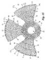
- FIG. 13is a diagrammatic plan view of a third embodiment according to the present invention.
- FIG. 14is a diagrammatic plan view of a fourth embodiment according to the present invention.
- FIG. 15is a diagrammatic plan view of a fifth embodiment according to the present invention.
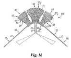
- FIG. 16is a diagrammatic plan view of a sixth embodiment according to the present invention.
- FIG. 17is a diagrammatic plan view showing a modified version of the sixth embodiment.
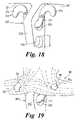
- FIG. 18is a schematic diagram of a metal prosthesis to which the sixth embodiment may be attached.
- FIG. 19is a diagrammatic view showing the modified sixth embodiment attached to the metal prosthesis of FIG. 18 ;
- FIG. 20is an enlarged schematic diagram of the modified sixth embodiment
- FIG. 21is a diagrammatic plan view of a seventh embodiment according to the present invention.
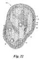
- FIG. 22is a diagrammatic plan view of an eighth embodiment according to the present invention.
- FIG. 23is a diagrammatic plan view of a ninth embodiment according to the present invention.
- FIG. 24is a diagrammatic sketch showing the ninth embodiment in situ.
- a textile prosthesis constructed in accordance with the principles of the present inventionis schematically illustrated in FIGS. 1 to 5 and comprises a body 10 which is composed of binding yarns 30 which are interconnected by sewn stitches and tensile load bearing yarns 20 which are encased within the body by being located in-between the binding yarn stitches.
- the sewn stitches of the binding yarns 30 and the placement of the tensile load bearing yarns 20are preferably created using embroidery techniques on a computer controlled embroidery machine, such as a Tajima or Barudan embroidery machine.
- Such a machineincludes a sewing head located above a base fabric and a looper head located below the base fabric.
- the sewing headsupplies a sewing thread which is preferably interlaced with a looper thread supplied by the looper head. Accordingly during the sewing operation a sewing thread is laid upon the upper surface of the base fabric and a looper thread is laid upon the lower surface of the base fabric.
- the base fabricis normally held in a frame which is moved under the control of the computer by a pantograph.
- any stitchmay be placed at any point within the embroidery frame, and the yarn length portions between successive stitches may be positioned at any angle and be of any length, subject to the dimensions of the embroidery frame.
- the base fabric on which the embroidery is performedmay be removed, preferably by dissolution in a suitable solvent, after completion of the embroidery operation in order to leave the textile prosthesis as a body having its own structural integrity.
- the base fabricmay remain to provide additional structural or tensile support.
- the body 10is illustrated as including two anchorage portions ST and B which when attached to two separate anatomical body parts transmits loads between those parts in a direction LD.
- the body 10may include any number of anchorage portions ST and/or B.
- the body 10may include only one anchorage body portion and this may be either a body portion ST or a body portion B.
- the binding yarns 30co-operate with the load bearing yarns 20 so that the load bearing yarns 20 are constrained to follow predetermined pathways through the body 10 .
- the binding yarns 30may interact with one another to define a non-stretchable stable ground fabric structure, preferably of mesh-like form MS as shown in greater detail in FIGS. 2 to 5 .
- the ground fabric structure MS shown in FIGS. 2 to 5includes a first series (FS) of stitches 31 of upper and lower binding yarns 30 a , 30 b having stitch lengths 35 extending in one direction and a second series (SS) of stitches 32 of upper and lower binding yarns 30 c , 30 d having stitch lengths 36 extending in a different direction, which in the illustrated example is 90° to the direction of the first series FS. It will be appreciated however that the directional angular relationship between the first and second series FS, SS may be greater or less than 90°.
- FIGS. 3 and 4a base fabric BF is shown into which the stitches 31 , 32 are formed. Base fabric BF is subsequently removed to form the mesh-like ground fabric MS.
- the stitches 31 , 32 of the binding yarns 30are spaced apart to define open spaces OS in the mesh-like fabric MS.
- the size of spaces OSmay be changed to vary the density of the mesh-like fabric as desired by for example changing the stitch length between adjacent stitches 31 or adjacent stitches 32 , changing the spacing between the series of stitches FS and SS, changing the size of the binding yarns 30 and/or introducing additional series of binding yarn stitches (i.e. have more than two series of stitches). For instance it is possible to create a relatively open mesh-like structure for promoting tissue ingrowth or a relatively closed mesh-like structure for inhibiting tissue ingrowth.
- the binding yarns 30may interact so as only to constrain the load bearing yarns 20 along said pathways.
- the stitching together of binding yarns 30may be performed so as to layer the binding yarns on top of one another in order to define a predetermined three dimensional shape to a predetermined region of the body 10 .
- the tensile load bearing yarns 20are placed so as to have length portions 21 which extend in the direction of a predetermined tensile load bearing direction LD of the prosthesis body. As seen more clearly in FIG. 5 , the tensile load bearing yarns 20 are located inbetween upper and lower stitch lengths 35 so as to be trapped within the mesh-like fabric MS.
- a precursor layer of binding yarns 20may be stitched into the base fabric which are subsequently overlaid by the load bearing yarn 20 .
- the precursor layermay be of any desired shape and extent in order to provide desired reinforcement and/or increased density of the body in selected areas.
- the stitches 31are closely spaced to the outer sides of the yarns 20 so that the stitch lengths 35 of the binding yarns act to restrain lateral displacement of the tensile load bearing yarns 20 .
- the stitches 31 and size of yarn 30are preferably chosen so that the length portions 35 are closely spaced side by side along the length portions 21 .
- Placement of the load bearing yarns 20may be performed by creating sewn stitches 27 between upper and lower yarns 20 a , 20 b (as seen in FIG. 5 ).
- the load bearing filament 20is supplied from the looper of the embroidery machine and the thread supplied from the needle of the sewing machine is chosen to be much finer than the load bearing filament so that when stitches are formed between the needle thread and the load bearing filament 20 , the load bearing filament remains flat against the base fabric and are not drawn through the base fabric by the needle thread.
- yarns 20may be placed in position by a laying-in technique wherein the yarns 20 are temporarily held in position whilst sewn stitches 31 are created. With laying-in techniques, a single yarn end of yarn 20 , or a desired multiple number of yam ends of yarn 20 may be laid-in during each laying-in process.
- the load bearing yarns 20are placed in position by creating stitches 27 between upper and lower yarns 20 a , 20 b.
- the stitch lengths 28 between adjacent stitches 27is preferably chosen to be the maximum distance required for ensuring correct directional placement of the yarns 20 during the embroidery process.
- the stitch lengths 28are relatively long along rectilinear length portions 21 whereas they are relatively short along curved length portions 21 a.
- each single series of stitches 27locates in place two yarns 20 . Accordingly, prior to encasing the yarns 20 within the binding yarns 30 , it will be appreciated that more than one series of stitches 27 may be created so that more than one pair of upper and lower yarns 20 a , 20 b are located inbetween each pair of stitch lengths 35 .
- the body 10includes an anchorage portion ST for attachment to an anatomical body part defined by soft tissue such as muscle.
- the anchorage portion ST of the present inventionis preferably defined by a planar areal portion of stretch resistive fabric formed by said binding and load bearing yarns.
- the binding yarns 30are preferably sewn together to define the mesh-like structure MS in which one series of stitches M 1 extend in one transverse direction across the load bearing yarn 20 and in which a second series of stitches M 2 extend in an opposite transverse direction across the load bearing yarn 20 .
- the mesh-like structure formed by the binding yarns 30in effect defines a ground fabric structure which is relatively non-stretchable and through which the load bearing yarns 30 are constrained to pass along predefined pathways.
- the mesh-structure MSis open to promote tissue ingrowth such that the anchorage portion ST is able to be secured biologically to soft tissue.
- the load bearing yarns 20are laid along a circuitous route through the anchorage body portion ST such that at certain locations within the body the load bearing yarn 20 is looped relative to the load bearing direction LD to define opposed loops 22 , 23 . Accordingly, when a load is applied in the load bearing direction LD, the load tends to tighten the loops 22 , 23 in direction LD and attempts to pull opposed loops 22 and loops 23 toward one another. However, such movement is resisted by the mesh-structure MS due to the loops 22 , 23 being trapped in the mesh-structure MS, and if provided, by the interaction of stitches 27 of the load bearing yarns 20 with the stitches 31 , 32 of the mesh structure MS.
- an anchoring threadsuch as a suture thread is passed through the mesh-like structure MS and into the soft tissue to which it is to be connected.
- the suture threadwill therefore pass through the open spaces OS in the mesh-like structure and will secure the mesh-like structure to the soft tissue. After tissue ingrowth, the mesh-like structure will also be biologically secured to the soft tissue.
- the mesh-like structurewill resist movement of opposed loops 22 , 23 toward one another and, due to the load bearing yarn 20 being constrained along a circuitous path across a relatively large areal portion, loads are dissipated over a relative large area to the soft tissue.
- the body 10 illustrated in FIG. 1also includes an anchorage portion B which is intended to enable the body 10 to be anchored to a relatively hard anatomical body part such as bone by a fixing means such as a screw.
- the anchorage portion Bincludes at least one aperture 18 and the arrangement shown in FIG. 6 demonstrates how an aperture 18 may be formed for accommodating a fixing means such as a bone screw.
- the tensile load bearing yarns 20extend around the circumference of the aperture 18 and are held in position by a star shaped stitch formation 40 , preferably formed from binding yarns 30 .
- the star formation 40is defined by successive stitches 41 , 42 which are spaced about the circumference of the aperture 18 .
- the stitches 41 , 42are spaced apart to embrace one or more yarns 20 .
- the yarn portions 45 which extend between successive stitches 41 , 42define reinforcement arms 44 which project radially outwardly from the aperture 18 . Accordingly when the prosthesis body is exposed to a tensile load, the yarn length portions 45 tend to be placed in tension to resist the applied load whilst maintaining anchorage of the yarns 20 .
- the load bearing yarn 20is illustrated as extending partly about the circumference of the aperture 18 . It is envisaged that the load bearing yarn 20 may extend continuously around the circumference of the aperture 18 for one or more turns.
- an additional reinforcement yarn 50may be included as shown in FIG. 7 .
- the reinforcement yarn 50is placed so as to extend continually around the circumference of the aperture 18 for a desirable number of turns to define an annulus 51 .
- the annulus 51 defined by the yarn 50is enclosed between successive stitches 41 , 42 .
- the annulus 50assists in resisting deformation of the shape of the aperture 18 when tensile loads are applied.
- FIGS. 6 and 7Although the shape of the aperture in FIGS. 6 and 7 is shown as circular, it will be appreciated that the same structural arrangement of the yarns may be adopted for forming apertures of any desirable shape, such as slot shaped.
- the aperture 18may be closed by fabric, for instance a mesh-like fabric created by binding yarns 30 .
- the aperture 18 constructed in accordance with FIG. 6 or 7may be formed in a mesh-like structure defined by binding yarns 30 .
- the binding yarns defining the stitch formation 40preferably interact with the binding yarns forming the mesh-like structure MS to anchor the stitch formation 40 to the mesh-like structure MS.
- the body 10may include a pull string or ribbon PS which is composed of the binding yarns 30 and load bearing yarns 20 .
- the load bearing yarns 20 of the string or ribbon PSare connected with the remainder of the body 10 , preferably by forming a continuation of the load bearing yarns 20 passing through the remainder of the body 10 , such that tensile loads applied to the ribbon PS are transmitted through the body 10 .
- Thisis advantageous in that it enables a surgeon to attach a first anchorage portion (in the case of FIG. 1 anchorage portion ST) and then pull on the ribbon PS to tension the body 10 whilst attaching the second anchorage portion B. This ensures that the load bearing yarns 20 extending between the anchorage portion ST and B are placed under a desired amount of tension.
- the ribbon PSmay then be severed and removed.
- the ribbon PSmay provide the surgeon with an alternative or additional means for securing the body 10 to an anatomical body part by tying the ribbon PS to that part.
- binding yarns 30 and load bearing yarns 20may be combined to create many different types of body 10 made up of various combinations of anchorage portions, fabric constructions and/or three dimensional shapes tailored for specific implant applications.
- FIG. 8there is shown a first embodiment which is a surgical implant suitable for the repair of the shoulder of a human being, intended to reinforce the natural, but damaged tissue.
- the implantcomprises a body 10 which is generally planar and includes a first discrete body portion 14 , a second discrete body portion 15 and a third discrete body portion 16 .
- the first body portion 14defines an anchorage body portion ST, comprising a mesh-like structure MS 1 formed from binding yarns 30 in which load bearing yarns 20 are trapped.
- the anchorage portion STis intended to be sutured to the natural tendon material forming the rotator cuff of the shoulder.
- the body portion 15defines an anchorage body portion B and preferably includes three apertures 18 each of which enable a bone screw to pass therethrough for securing the body portion 15 to the humeral bone.
- Three apertures 18are provided in order to provide alternative sites for the bone screw and/or provide a plurality of sites for enabling more than one bone screw to be used.
- the number of apertures 18may be less or more than three.
- the apertures 18each have a structure based upon that described with reference to FIGS. 6 and 7 .
- the body portion 16defines ribbon PS to enable the surgeon to pull the body 10 after attaching body portion 14 so as to apply tension prior to attaching body portion 15 .
- body portion 16may be removed by severance from body portion 15 .
- the body 10is constructed using a plurality of yarns which are interconnected by sewn stitches.
- the structure of the implant 10is more clearly shown in FIG. 9 .
- the tensile load bearing yarn 20is placed upon the base fabric (not shown) by stitches 27 being formed between upper and lower yarns 20 a , 20 b at least at each point of change of direction for the yarn 20 . This provides long length portions 21 of yarn 20 .
- the yarn 20runs continuously from the terminal end of body portion 14 , through body portion 15 and into body portion 16 .
- the same yarn 20(composed of one or more yarn ends which are either stitched together or laid-in) is placed along a circuitous route so as to pass continuously along body portions 14 , 15 and 16 and to extend continuously across the area of body portion 14 .
- yarn 20starts outside body 12 at point SP and finishes outside body 12 at point FP.
- the yarn 20is placed within body portion 15 so as to define a window 17 corresponding to the location of apertures 18 .
- Annuli 51 of reinforcement yarn 50are placed upon the yarn portions 21 of body portion 15 and star formations 40 are then placed so as to contain the spirals 51 and also the yarn portions 21 .
- binding yarns 30are placed in position by creating successive stitches to form the mesh-like structure MS, which encase the tensile load bearing yarns 20 as described above.
- FIGS. 10 , 11A modified construction of the anchorage portion B for the first embodiment is illustrated in FIGS. 10 , 11 .
- the load bearing yarn 20instead of extending to define an elongate window 17 , extend around the apertures 18 and are encased within star formations 40 .
- the yarn 20is laid along a pathway which, in effect, defines chain-links 28 (shown schematically in FIG. 11 ) which are each joined about an aperture 18 .
- connection between the chain-links 28ensures that loads applied in direction LD between the anchorage body portion ST and pulling ribbon PS are transmitted through body portion 15 without causing distortion.
- the chain-links 28are each self-supporting such that if one chain link 28 is severed, the load bearing capability of the next adjacent chain link 28 is unaffected.
- the body portion 15may be severed along line S v to enable the surgeon to remove the pulling ribbon PS and the remaining portion of body portion 15 attached thereto. After severance along line S v , the chain-link 28 a is still intact and so is able to transmit loads between aperture 18 b and the anchorage portion ST.
- Formation of each chain-link 28is preferably achieved as illustrated schematically in FIG. 11 .
- a first chain-link 128is formed by placing load bearing yarn 20 along a looped path as indicated by single arrows A 1 about a first pair of adjacent apertures 18 a,b .
- the shape of the looped pathis determined by location of stitches 27 between upper and lower yarns 20 a , 20 b and creates a relatively long rectilinear link portion 130 and a curved link portion 131 which extends approximately halfway about the circumference of aperture 18 .
- the yarn 20is looped for a desired number of turns, for example 6 turns, and then is looped along the next adjacent looped path as indicated by double arrow A 2 about a second pair of adjacent apertures 18 b , 18 c . The process is then repeated to create the next chain-link 28 .
- star formations 40 and/or annuli 51are provided to reinforce each aperture 18 .
- FIG. 12a prosthesis 300 is illustrated which includes several anchorage apertures 18 which are inter-linked by chain-links 28 to provide a spread of loadings in several different directions.
- apertures 18 a , 18 bare interconnected by a chain-link 28 a .
- Aperture 18 bis inter-linked with two additional apertures 18 c , 18 d by chain-links 28 b and 28 c respectively.
- FIG. 13a prosthesis 400 suitable for use as an anterior spinal plate is illustrated.
- the prosthesis 400includes six arms 401 each formed by a series of apertures 18 interconnected by chain-links 28 .
- the arms 401radiate from three main fixation apertures 18 a , 18 b and 18 c .
- These apertures 18 a , 18 b and 18 care attached to the LS vertebra of a patient and the arms 401 are attached to the sacrum. Due to the multiplicity of arms 401 and the plurality of apertures 18 they contain, it is possible to obtain good anchorage on the complex, three dimensional shape of the sacrum.
- each of the outer pair of arms 401is preferably interconnected by a link 28 a to at least two of the apertures 18 a - 18 c in order to provide a desired spread of loadings.
- FIG. 14there is illustrated a prosthesis 500 which is suitable for use as a spinal strap for securing together adjacent vertebrae in a spine.
- the prosthesis 500includes two apertures 18 a , 18 b which are interconnected by a chain-link 28 formed by load bearing filament 20 .
- Load bearing filaments 20are preferably also directed between the apertures 18 a , 18 b to define diagonal portions 28 c .
- the diagonal portions 28 cenable the strap to be twisted without losing its load bearing efficiency.
- the load bearing filaments 20are encased within a mesh structure MS defined by binding yarns 30 .
- the central region MSd of the mesh structureis denser than the remainder of the mesh structure MS in order to resist the load bearing filaments cutting into the bone of the vertebrae of the spine. It is envisaged that the chain-link portions 28 a which extend between apertures 18 a , 18 b may be omitted such that apertures 18 a , 18 b are interconnected by diagonal portions 28 c only.
- apertures 18 a and 18 bare not lying in the same two dimensional plane in that the diagonal links 18 c facilitate an element of axial twist while maintaining overall tension between the apertures.
- FIG. 15there is shown a second embodiment 60 of the present invention which is a prosthesis having three anchorage body portions ST 1 , ST 2 , ST 3 defined by body portions 61 , 62 and 63 each of which is designed to be attached to one of the three tendons of the rotator cuff.
- the body portions 61 , 62 and 63extend from an annular body portion 67 having a central hole 68 .
- the annular body portionis formed from an annulus 51 and a star formation 40 .
- the yarn 20extends from each body portion 61 , 62 , 63 to be securely anchored by the star formation 40 and the binding yarns 30 .
- the body portions 61 , 62 and 63are generally of fan shape and the yarn portions 21 of the tensile load bearing yarn are preferably provided with intermediate loop portions 27 to provide substantially equal spacing between yarn portions 21 despite the fanning out of the yarn portions as the fan shaped body portion becomes wider.
- Each of the body portions 61 , 62 and 63is preferably constituted by said mesh-like structure MS and preferably has additional reinforcement yarns 66 running circumferentially to the central hole 68 .
- This additional reinforcement yarn 66is intended to aid and assist the surgeon in placing the stitches to retain the wing of the implant to the tendon, and also indicate a site beyond which the device can be cut or trimmed to shape, the radially extending yarn portions 21 providing an extra strength area to minimise the possibility of any disintegration of the textile structure.
- the region of the central hole 68through which fits the stem of a modular humeral head, is reinforced using an annulus 51 and star formation 40 and these in combination with the binding yarns 30 hold the tensile load bearing yarns 20 running out into the body portions 61 , 62 , 63 .
- Thisis desirable as the load bearing on the prosthesis 60 can be quite high in the first phase of the rehabilitation of the patient.
- the embodiment 80 illustrated in FIG. 16is a multiple ligament reinforcement prosthesis.
- Prosthesis 80includes three fan shaped anchorage body portions ST 1 , ST 2 , ST 3 defined by body portions 81 , 82 and 83 which are joined together by a connecting body portion 84 .
- the body portions 81 , 82 and 83are of a similar structure to body portions 61 , 62 , 63 described above with the exception that the reinforcement yarn 66 is replaced by a reinforcement yarn 86 which is placed by a succession of stitches 87 which define arcuate zig-zag formations 88 which serve to prevent the fabric fraying after a surgeon has cut inbetween the formations 88 .
- the yarn 86has a contrasting colour to the other yarns in order to give the surgeon an easily recognisable guide for cutting.
- the prosthesis 80includes two arm portions 90 which form pulling ribbons PS connected to body portion 84 .
- Load bearing yarns 20extend continuously through both arm portions 90 and the connecting body portion 84 .
- Arm portions 90assist in the securing of the textile prosthesis to a metal prosthesis anchored within the bone of the patient.
- additional ribbons 91 of similar structure to arms 90depend from the connecting body portion 84 for further assisting in the anchoring of the textile prosthesis around the metal prosthesis.
- the prosthesis 80may be modified to incorporate a pair of apertures 85 for enabling the prosthesis 80 to be connected to the metal prosthesis.
- FIG. 18a suitable metal prosthesis 300 is illustrated in FIG. 18 which has a body 301 intended to be attached, by for example bone screws, to a bone of the patient.
- the body 301includes a flange 303 which includes at least one bore 304 passing therethrough.
- An anchor member 310is provided which has a generally U-shaped body 311 which can be inserted through a bore 304 as illustrated.
- the body 311has two arms 312 which have hook formations 314 at their terminal ends.
- the hook formations 314are spaced apart by a distance corresponding to the distance between apertures 85 to thereby enable the prosthesis 80 to be attached to the anchor member 310 by inserting the hook formations 314 into apertures 85 .
- the load bearing yarns 20 extending through an arm portion 90preferably loops around the nearest aperture 85 . This enables the arm portion 90 to directly transmit loads along the load bearing yarn 20 from the hook portion 314 passing through the aperture 85 .
- load bearing yarns 20which extend through the central body portion 82 also loop around apertures 85 to enable loads to be directly transmitted from the hook formations 314 and in a direction along the length of the central body portion 82 .
- Embodiment 100 illustrated in FIG. 21comprises a body 12 having two discrete anchorage body portions B 1 , B 2 defined by two body portions 101 , 102 which are connected to one another only by tensile load bearing yarn length portions 21 .
- the yarn 20is secured within body portions 101 , 102 by star formations 40 and binding yarns 30 which preferably form a mesh-like structure MS.
- the yarn lengths 21cross over from right to left and left to right as they extend between the body portions 101 , 102 .
- each length portion 21is of a predetermined length so that all length portions 21 have the same tensile load applied thereto when body portions 101 , 102 are pulled part. This has the advantage that there will not be a cascade failure of one yarn length 21 breaking after another once a first one of the lengths 21 has broken.
- Embodiment 110 illustrated in FIG. 22is a textile prosthesis in the shape of an ear.
- the prosthesis 110includes three apertures 18 for bone screws (not shown). Each of the apertures 18 are formed by an annulus 51 and star formation 40 as described above.
- Tensile load bearing yarns 20extend through the body of the prosthesis along a predetermined circuitous path in order to provide reinforcement at desired locations and provide desired shape and volume to the prosthesis.
- the prosthesis 110may be placed in a cell culture medium to allow tissue ingrowth into the textile fabric of the prosthesis before being placed in position adjacent to the head of the patient to allow further tissue ingrowth from the body of the patient.
- Embodiment 120 illustrated in FIGS. 23 , 24is an example of a prosthesis according to the invention which can be used as an automotive transfer device.
- the automotive transfer device of FIG. 23is intended for generating movement about the elbow of a patient.
- the prosthesisincludes a body 10 having a first discrete region 121 , a second discrete region 122 and a third discrete region 123 .
- the first region 121is defined by an anchorage body portion ST which is intended to be wrapped about and secured to the posterior deltoid muscle DM as shown schematically in FIG. 23 .
- the anchorage portion STis first secured by suturing and then biologically by tissue ingrowth.
- the third discrete region 123is secured to the lower arm, for example by a bone anchor or a screw.
- the second region 122In order to enable contractions of the posterior deltoid muscle to be translated into axial displacement of the third region 123 , it is necessary for the intermediate, second discrete region 122 to remain free to move axially relative to the tissue of the patient through which it passes (typically just underneath the patients' skin).
- the second region 122therefore includes a closed mesh-like structure MS c formed from binding yarns 30 which discourages tissue ingrowth.
- the same type of yarnis used for both the sewing and looper heads of the embroidery machine.
- the yarn used for the tensile load bearing yarn 20is preferably a polyester braided thread as used for sutures.
- the load bearing yarn 20has a diametric size varying between 0.2 to 0.5 mm, more preferably is about 0.35 mm.
- Other types of yarncould also be used if desired, for example polypropylene, polyethylene, polyamide.
- a yarninstead of a yarn, other types of material made into filaments may be used, eg. wire of suitable metals such as a SMA (Shape Memory Alloy), aramid fibres, glass strands, etc.
- SMAShape Memory Alloy
- aramid fibresglass strands, etc.
- any filament having the desired tensile load bearing capabilities and flexibility for bending to lie along a circuitous pathwaymay be used.
- the yarn used for the binding yarns 30is also a polyester braided thread.
- the binding yarn 30has a diametric size varying between 0.1 to 0.2 mm.
- the present inventionprovides an improved method of placing fibres so as to manufacture textile prostheses, such as surgical implants (and other products), whereby the fabric structure of body portions of the prosthesis are stronger and/or have better integrity and/or have better load spreading characteristics and/or have better load concentration characteristics and/or exhibit less distortion around holes, and/or are stronger and/or distort less under load and/or creep less under load and/or have improved mesh characteristics to improve tissue ingrowth and/or have a structure intended to reduce tissue ingrowth.
- textile prosthesessuch as surgical implants (and other products)
- the textile connector of the present inventionmay also form reinforcement for encapsulation within a matrix material, e.g. a synthetic resin, in order to form a composite component or may have elements that are encapsulated in a matrix material and elements that extend outside the matrix material, i.e. elements which are unconstrained.
- a matrix materiale.g. a synthetic resin
Landscapes
- Health & Medical Sciences (AREA)
- Orthopedic Medicine & Surgery (AREA)
- Life Sciences & Earth Sciences (AREA)
- Neurology (AREA)
- Surgery (AREA)
- General Health & Medical Sciences (AREA)
- Public Health (AREA)
- Biomedical Technology (AREA)
- Heart & Thoracic Surgery (AREA)
- Veterinary Medicine (AREA)
- Engineering & Computer Science (AREA)
- Animal Behavior & Ethology (AREA)
- Molecular Biology (AREA)
- Nuclear Medicine, Radiotherapy & Molecular Imaging (AREA)
- Medical Informatics (AREA)
- Cardiology (AREA)
- Oral & Maxillofacial Surgery (AREA)
- Transplantation (AREA)
- Vascular Medicine (AREA)
- Neurosurgery (AREA)
- Rehabilitation Therapy (AREA)
- Rheumatology (AREA)
- Prostheses (AREA)
- Materials For Medical Uses (AREA)
Abstract
Description
Claims (30)
Priority Applications (2)
| Application Number | Priority Date | Filing Date | Title |
|---|---|---|---|
| US12/042,311US7828855B2 (en) | 2000-10-11 | 2008-03-04 | Textile prosthesis |
| US12/942,372US20110054610A1 (en) | 2000-10-11 | 2010-11-09 | Textile Prosthesis |
Applications Claiming Priority (3)
| Application Number | Priority Date | Filing Date | Title |
|---|---|---|---|
| GB0024903.7 | 2000-10-11 | ||
| GBGB0024903.7AGB0024903D0 (en) | 2000-10-11 | 2000-10-11 | A textile prothesis |
| PCT/GB2001/004512WO2002030324A1 (en) | 2000-10-11 | 2001-10-11 | A textile prosthesis |
Related Child Applications (1)
| Application Number | Title | Priority Date | Filing Date |
|---|---|---|---|
| US12/042,311DivisionUS7828855B2 (en) | 2000-10-11 | 2008-03-04 | Textile prosthesis |
Publications (2)
| Publication Number | Publication Date |
|---|---|
| US20040078089A1 US20040078089A1 (en) | 2004-04-22 |
| US7338531B2true US7338531B2 (en) | 2008-03-04 |
Family
ID=9901082
Family Applications (3)
| Application Number | Title | Priority Date | Filing Date |
|---|---|---|---|
| US10/398,883Expired - LifetimeUS7338531B2 (en) | 2000-10-11 | 2001-10-11 | Textile prosthesis |
| US12/042,311Expired - Fee RelatedUS7828855B2 (en) | 2000-10-11 | 2008-03-04 | Textile prosthesis |
| US12/942,372AbandonedUS20110054610A1 (en) | 2000-10-11 | 2010-11-09 | Textile Prosthesis |
Family Applications After (2)
| Application Number | Title | Priority Date | Filing Date |
|---|---|---|---|
| US12/042,311Expired - Fee RelatedUS7828855B2 (en) | 2000-10-11 | 2008-03-04 | Textile prosthesis |
| US12/942,372AbandonedUS20110054610A1 (en) | 2000-10-11 | 2010-11-09 | Textile Prosthesis |
Country Status (10)
| Country | Link |
|---|---|
| US (3) | US7338531B2 (en) |
| EP (1) | EP1326554B1 (en) |
| JP (1) | JP4083008B2 (en) |
| KR (1) | KR20030066640A (en) |
| AT (1) | ATE332111T1 (en) |
| AU (1) | AU2001293990A1 (en) |
| DE (1) | DE60121354T2 (en) |
| GB (1) | GB0024903D0 (en) |
| WO (1) | WO2002030324A1 (en) |
| ZA (1) | ZA200303605B (en) |
Cited By (37)
| Publication number | Priority date | Publication date | Assignee | Title |
|---|---|---|---|---|
| US20040224406A1 (en)* | 2001-11-16 | 2004-11-11 | Tissue Regeneration, Inc. | Immunoneutral silk-fiber-based medical devices |
| US20070208342A1 (en)* | 2000-10-11 | 2007-09-06 | Julian Ellis | Connector |
| US20080173223A1 (en)* | 2007-01-22 | 2008-07-24 | Nuvasive, Inc. | 3-dimensional embroidery structures via tension shaping |
| US20080178786A1 (en)* | 2007-01-31 | 2008-07-31 | Nuvasive, Inc. | Using zigzags to create three-dimensional embroidered structures |
| US20080188936A1 (en)* | 2007-02-02 | 2008-08-07 | Tornier, Inc. | System and method for repairing tendons and ligaments |
| US20080228028A1 (en)* | 2007-03-12 | 2008-09-18 | Cook Incorporated | Woven fabric with shape memory element strands |
| US20080306593A1 (en)* | 2004-03-26 | 2008-12-11 | Mcleod Alan Rory Mor | Prosthetic Spinal Disc |
| US20090018655A1 (en)* | 2007-07-13 | 2009-01-15 | John Brunelle | Composite Implant for Surgical Repair |
| US20090024165A1 (en)* | 2007-07-17 | 2009-01-22 | Ferree Bret A | Methods of annulus and ligament reconstruction using flexible devices |
| US20090138082A1 (en)* | 2007-11-19 | 2009-05-28 | Nuvasive, Inc. | Textile-Based Plate Implant and Related Methods |
| US20090171443A1 (en)* | 2007-12-27 | 2009-07-02 | Cook Incorporated | Stent graft having floating yarns |
| US20090318960A1 (en)* | 2006-02-01 | 2009-12-24 | Burkhart Stephen S | Method of knotless tissue fixation with criss-cross suture pattern |
| US20100063599A1 (en)* | 2008-09-05 | 2010-03-11 | Pegasus Biologics, Inc. | Device for soft tissue repair or replacement |
| US20100089297A1 (en)* | 2006-09-25 | 2010-04-15 | Peter Butcher | Embroidery Using Soluble Thread |
| US7713463B1 (en) | 2007-11-13 | 2010-05-11 | Nuvasive, Inc. | Method of manufacturing embroidered surgical implants |
| US20100249930A1 (en)* | 2009-03-31 | 2010-09-30 | Medicinelodge, Inc. Dba Imds Co-Innovation | Double bundle acl repair |
| US20110009960A1 (en)* | 2001-11-16 | 2011-01-13 | Allergan, Inc. | Prosthetic fabric structure |
| US20110054610A1 (en)* | 2000-10-11 | 2011-03-03 | Julian Ellis | Textile Prosthesis |
| US20110184227A1 (en)* | 2009-09-11 | 2011-07-28 | Allergan, Inc. | Prosthetic device and method of manufacturing the same |
| US20110213467A1 (en)* | 2009-01-20 | 2011-09-01 | Zimmer, Inc. | Orthopaedic implant with woven ingrowth material |
| US20110224703A1 (en)* | 2008-12-15 | 2011-09-15 | Allergan, Inc. | Prosthetic device having diagonal yarns and method of manufacturing the same |
| US8282681B2 (en) | 2007-08-13 | 2012-10-09 | Nuvasive, Inc. | Bioresorbable spinal implant and related methods |
| US8377135B1 (en) | 2008-03-31 | 2013-02-19 | Nuvasive, Inc. | Textile-based surgical implant and related methods |
| US8746014B2 (en) | 2008-12-15 | 2014-06-10 | Allergan, Inc. | Method for making a knitted mesh |
| US8968402B2 (en) | 2011-10-18 | 2015-03-03 | Arthrocare Corporation | ACL implants, instruments, and methods |
| US20150148823A1 (en)* | 2008-12-15 | 2015-05-28 | Allergan, Inc. | Pliable silk medical device |
| US9204953B2 (en) | 2008-12-15 | 2015-12-08 | Allergan, Inc. | Biocompatible surgical scaffold with varying stretch |
| US9326840B2 (en) | 2008-12-15 | 2016-05-03 | Allergan, Inc. | Prosthetic device and method of manufacturing the same |
| US10321833B2 (en) | 2016-10-05 | 2019-06-18 | Innovative Surgical Solutions. | Neural locating method |
| US10376208B2 (en) | 2013-09-20 | 2019-08-13 | Innovative Surgical Solutions, Llc | Nerve mapping system |
| US10376209B2 (en) | 2013-09-20 | 2019-08-13 | Innovative Surgical Solutions, Llc | Neural locating method |
| US10449002B2 (en) | 2013-09-20 | 2019-10-22 | Innovative Surgical Solutions, Llc | Method of mapping a nerve |
| US10478097B2 (en) | 2013-08-13 | 2019-11-19 | Innovative Surgical Solutions | Neural event detection |
| US10478096B2 (en) | 2013-08-13 | 2019-11-19 | Innovative Surgical Solutions. | Neural event detection |
| US10870002B2 (en) | 2018-10-12 | 2020-12-22 | DePuy Synthes Products, Inc. | Neuromuscular sensing device with multi-sensor array |
| US10869616B2 (en) | 2018-06-01 | 2020-12-22 | DePuy Synthes Products, Inc. | Neural event detection |
| US11399777B2 (en) | 2019-09-27 | 2022-08-02 | DePuy Synthes Products, Inc. | Intraoperative neural monitoring system and method |
Families Citing this family (58)
| Publication number | Priority date | Publication date | Assignee | Title |
|---|---|---|---|---|
| CA2365376C (en) | 2000-12-21 | 2006-03-28 | Ethicon, Inc. | Use of reinforced foam implants with enhanced integrity for soft tissue repair and regeneration |
| US8512376B2 (en) | 2002-08-30 | 2013-08-20 | Arthrex, Inc. | Method and apparatus for internal fixation of an acromioclavicular joint dislocation of the shoulder |
| US20040078090A1 (en) | 2002-10-18 | 2004-04-22 | Francois Binette | Biocompatible scaffolds with tissue fragments |
| US8197837B2 (en) | 2003-03-07 | 2012-06-12 | Depuy Mitek, Inc. | Method of preparation of bioabsorbable porous reinforced tissue implants and implants thereof |
| US8226715B2 (en)* | 2003-06-30 | 2012-07-24 | Depuy Mitek, Inc. | Scaffold for connective tissue repair |
| US10583220B2 (en) | 2003-08-11 | 2020-03-10 | DePuy Synthes Products, Inc. | Method and apparatus for resurfacing an articular surface |
| US11395865B2 (en) | 2004-02-09 | 2022-07-26 | DePuy Synthes Products, Inc. | Scaffolds with viable tissue |
| WO2005112833A1 (en)* | 2004-05-20 | 2005-12-01 | Pearsalls Limited | Improvements in and relating to surgical implants |
| WO2006133130A2 (en)* | 2005-06-03 | 2006-12-14 | Nuvasive, Inc. | Fibrous spinal implant and method of implantation |
| US7862592B2 (en)* | 2005-12-06 | 2011-01-04 | Nuvasive, Inc. | Methods and apparatus for treating spinal stenosis |
| EP1832246B1 (en)* | 2006-03-08 | 2019-06-12 | Arthrex, Inc. | Bundle graft and method of making same |
| US20080009900A1 (en)* | 2006-06-12 | 2008-01-10 | Kfx Medical Corporation | Surgical grasping device |
| WO2008024920A1 (en)* | 2006-08-24 | 2008-02-28 | Wilson-Cook Medical Inc. | Devices and methods for occluding a fistula |
| WO2008098125A2 (en)* | 2007-02-08 | 2008-08-14 | Nuvasive, Inc. | Medical implants with pre-settled cores and related methods |
| CA2682701A1 (en)* | 2007-03-20 | 2008-09-25 | Serica Technologies, Inc. | Prosthetic device and method of manufacturing the same |
| US20110060366A1 (en)* | 2007-06-29 | 2011-03-10 | Stephen Heim | Facet Joint Implant and Related Methods |
| US9492270B2 (en)* | 2007-09-12 | 2016-11-15 | Alan Joel Melvin | Medical device and tension member for use in a subject |
| WO2009047767A1 (en)* | 2007-10-11 | 2009-04-16 | Tavor [I.T.N] Ltd. | Ligament and tendon prosthesis |
| GB2460041A (en)* | 2008-05-13 | 2009-11-18 | Surgicraft Ltd | A replacement ligament formed from components having different characteristics under load. |
| WO2010059789A2 (en)* | 2008-11-20 | 2010-05-27 | Lifecell Corporation | Method for treatment and prevention of parastomal hernias |
| US8439976B2 (en)* | 2009-03-31 | 2013-05-14 | Arthrex, Inc. | Integrated adjustable button-suture-graft construct with two fixation devices |
| US8460379B2 (en) | 2009-03-31 | 2013-06-11 | Arthrex, Inc. | Adjustable suture button construct and methods of tissue reconstruction |
| GB2474866B8 (en) | 2009-10-29 | 2013-04-10 | Xiros Ltd | Knot slip resistant woven cord |
| EP2536340B1 (en)* | 2010-02-19 | 2018-10-17 | LifeCell Corporation | Abdominal wall treatment devices |
| EP2387970B1 (en) | 2010-05-17 | 2013-07-03 | Tornier, Inc. | Endoprosthetic textile scaffold, especially for repairing rotator cuff tissue of human shoulder |
| EP2455040B1 (en) | 2010-11-17 | 2015-03-04 | Arthrex, Inc. | Adjustable suture-button construct for knotless stabilization of cranial cruciate deficient ligament stifle |
| EP2455001B1 (en) | 2010-11-17 | 2020-07-22 | Arthrex, Inc. | Adjustable suture-button constructs for ligament reconstruction |
| EP2455002B1 (en) | 2010-11-17 | 2019-04-03 | Arthrex, Inc. | Adjustable suture-button construct for ankle syndesmosis repair |
| US9301745B2 (en) | 2011-07-21 | 2016-04-05 | Arthrex, Inc. | Knotless suture constructs |
| US9332979B2 (en) | 2011-07-22 | 2016-05-10 | Arthrex, Inc. | Tensionable knotless acromioclavicular repairs and constructs |
| GB201113303D0 (en) | 2011-08-02 | 2011-09-14 | Xiros Ltd | Connective tissue repair pad |
| US20150127103A1 (en) | 2011-08-02 | 2015-05-07 | Xiros Limited | Connective tissue repair |
| US9107653B2 (en) | 2011-09-22 | 2015-08-18 | Arthrex, Inc. | Tensionable knotless anchors with splice and methods of tissue repair |
| US10245016B2 (en) | 2011-10-12 | 2019-04-02 | Arthrex, Inc. | Adjustable self-locking loop constructs for tissue repairs and reconstructions |
| EP2601894B1 (en) | 2011-12-09 | 2018-08-29 | Arthrex, Inc. | Tensionable knotless anchor systems |
| ES2726105T3 (en) | 2011-12-20 | 2019-10-01 | Lifecell Corp | Fluidizable fabric products |
| AU2012355463C1 (en) | 2011-12-20 | 2016-09-22 | Lifecell Corporation | Sheet tissue products |
| AU2013212592B2 (en) | 2012-01-24 | 2016-06-30 | Lifecell Corporation | Elongated tissue matrices |
| BR112014026088B1 (en) | 2012-04-24 | 2019-11-05 | Lifecell Corp | tissue treatment product |
| US9737292B2 (en) | 2012-06-22 | 2017-08-22 | Arthrex, Inc. | Knotless suture anchors and methods of tissue repair |
| GB201301784D0 (en) | 2013-02-01 | 2013-03-20 | Xiros Ltd | Connective tissue repair technology |
| GB201302114D0 (en) | 2013-02-06 | 2013-03-20 | Xiros Ltd | Connective tissue repair |
| US10213284B2 (en) | 2015-06-30 | 2019-02-26 | Tela Bio, Inc. | Corner-lock stitch patterns |
| EP3324882B1 (en) | 2015-07-21 | 2023-10-25 | Tela Bio, Inc. | Compliance control stitching in substrate materials |
| US10335136B2 (en) | 2015-08-20 | 2019-07-02 | Arthrex, Inc. | Tensionable constructs with multi-limb locking mechanism through single splice and methods of tissue repair |
| US10265060B2 (en) | 2015-08-20 | 2019-04-23 | Arthrex, Inc. | Tensionable constructs with multi-limb locking mechanism through single splice and methods of tissue repair |
| WO2017189772A1 (en) | 2016-04-26 | 2017-11-02 | Tela Bio, Inc. | Hernia repair grafts having anti-adhesion barriers |
| US11324282B2 (en) | 2016-05-16 | 2022-05-10 | Adidas Ag | Three-dimensionally thermo-molded footwear |
| WO2018037257A1 (en)* | 2016-08-22 | 2018-03-01 | Giuseppe Calvosa | Artificial ligament for acromioclavicular luxation |
| US10265160B2 (en) | 2017-01-04 | 2019-04-23 | Arthrex, Inc. | Embroidered textile support a biological graft |
| US10575842B2 (en) | 2017-02-09 | 2020-03-03 | Arthrex, Inc. | Knotless self-locking anchor constructs and methods of tissue fixation |
| US10646327B2 (en) | 2017-02-09 | 2020-05-12 | Arthrex, Inc. | Self-locking suture constructs and methods of tissue fixation |
| US10694817B2 (en) | 2017-03-07 | 2020-06-30 | Adidas Ag | Article of footwear with upper having stitched polymer thread pattern and methods of making the same |
| US10194714B2 (en)* | 2017-03-07 | 2019-02-05 | Adidas Ag | Article of footwear with upper having stitched polymer thread pattern and methods of making the same |
| EP3761963B1 (en) | 2018-03-09 | 2025-01-22 | Tela Bio, Inc. | Surgical repair graft |
| EP3653171B1 (en) | 2018-11-16 | 2024-08-21 | Sofradim Production | Implants suitable for soft tissue repair |
| EP4585235A3 (en) | 2019-03-08 | 2025-08-20 | Tela Bio, Inc. | Textured medical textiles |
| US20230103592A1 (en)* | 2021-10-01 | 2023-04-06 | Ahmadreza Afshar | Surgical device and method for repairing damaged flexor tendons |
Citations (12)
| Publication number | Priority date | Publication date | Assignee | Title |
|---|---|---|---|---|
| US4776851A (en)* | 1986-07-23 | 1988-10-11 | Bruchman William C | Mechanical ligament |
| US4790850A (en)* | 1986-03-14 | 1988-12-13 | Richards Medical Company | Phosthetic ligament |
| EP0314412A1 (en)* | 1987-10-30 | 1989-05-03 | Howmedica Inc. | Device for tendon and ligament repair |
| US4946377A (en)* | 1989-11-06 | 1990-08-07 | W. L. Gore & Associates, Inc. | Tissue repair device |
| WO1990011735A1 (en)* | 1989-04-01 | 1990-10-18 | Ellis Developments Limited | A prosthetic ligament |
| US5004474A (en)* | 1989-11-28 | 1991-04-02 | Baxter International Inc. | Prosthetic anterior cruciate ligament design |
| US5192322A (en)* | 1990-01-08 | 1993-03-09 | Sulzer Brothers Limited | Implant for a prosthetic ligament and/or tendon replacement |
| US5540703A (en)* | 1993-01-06 | 1996-07-30 | Smith & Nephew Richards Inc. | Knotted cable attachment apparatus formed of braided polymeric fibers |
| EP0744162A2 (en)* | 1995-05-25 | 1996-11-27 | Ellis Developments Limited | Textile surgical implants |
| US5800543A (en)* | 1993-03-31 | 1998-09-01 | Surgicraft Limited | Artificial ligament |
| WO2002030306A1 (en) | 2000-10-11 | 2002-04-18 | Ellis Developments Limited | A connector |
| US20040078089A1 (en)* | 2000-10-11 | 2004-04-22 | Julian Ellis | Textile prosthesis |
Family Cites Families (3)
| Publication number | Priority date | Publication date | Assignee | Title |
|---|---|---|---|---|
| FR2666219B1 (en)* | 1990-08-30 | 1997-12-12 | Peyrou Pierre | PROSTHETIC LIGAMENT FOR THE STRENGTHENING OF THE VERTICALIZED JOINT TENDON BY TURNING THE EXTERNAL FIBERS OF THE TENDON. |
| BR9907209A (en)* | 1998-01-26 | 2000-10-03 | Anson Medical Ltd | Graft with a flexible sheet sewn to a reinforcement wire |
| WO2008039497A2 (en)* | 2006-09-25 | 2008-04-03 | Nuvasive, Inc | Embroidery using soluble thread |
- 2000
- 2000-10-11GBGBGB0024903.7Apatent/GB0024903D0/ennot_activeCeased
- 2001
- 2001-10-11JPJP2002533772Apatent/JP4083008B2/ennot_activeExpired - Lifetime
- 2001-10-11USUS10/398,883patent/US7338531B2/ennot_activeExpired - Lifetime
- 2001-10-11ATAT01974475Tpatent/ATE332111T1/ennot_activeIP Right Cessation
- 2001-10-11AUAU2001293990Apatent/AU2001293990A1/ennot_activeAbandoned
- 2001-10-11KRKR10-2003-7005179Apatent/KR20030066640A/ennot_activeAbandoned
- 2001-10-11WOPCT/GB2001/004512patent/WO2002030324A1/enactiveIP Right Grant
- 2001-10-11DEDE60121354Tpatent/DE60121354T2/ennot_activeExpired - Lifetime
- 2001-10-11EPEP01974475Apatent/EP1326554B1/ennot_activeExpired - Lifetime
- 2003
- 2003-05-09ZAZA200303605Apatent/ZA200303605B/enunknown
- 2008
- 2008-03-04USUS12/042,311patent/US7828855B2/ennot_activeExpired - Fee Related
- 2010
- 2010-11-09USUS12/942,372patent/US20110054610A1/ennot_activeAbandoned
Patent Citations (13)
| Publication number | Priority date | Publication date | Assignee | Title |
|---|---|---|---|---|
| US4790850A (en)* | 1986-03-14 | 1988-12-13 | Richards Medical Company | Phosthetic ligament |
| US4776851A (en)* | 1986-07-23 | 1988-10-11 | Bruchman William C | Mechanical ligament |
| EP0314412A1 (en)* | 1987-10-30 | 1989-05-03 | Howmedica Inc. | Device for tendon and ligament repair |
| WO1990011735A1 (en)* | 1989-04-01 | 1990-10-18 | Ellis Developments Limited | A prosthetic ligament |
| US4946377A (en)* | 1989-11-06 | 1990-08-07 | W. L. Gore & Associates, Inc. | Tissue repair device |
| US5004474A (en)* | 1989-11-28 | 1991-04-02 | Baxter International Inc. | Prosthetic anterior cruciate ligament design |
| US5192322A (en)* | 1990-01-08 | 1993-03-09 | Sulzer Brothers Limited | Implant for a prosthetic ligament and/or tendon replacement |
| US5540703A (en)* | 1993-01-06 | 1996-07-30 | Smith & Nephew Richards Inc. | Knotted cable attachment apparatus formed of braided polymeric fibers |
| US5800543A (en)* | 1993-03-31 | 1998-09-01 | Surgicraft Limited | Artificial ligament |
| EP0744162A2 (en)* | 1995-05-25 | 1996-11-27 | Ellis Developments Limited | Textile surgical implants |
| WO2002030306A1 (en) | 2000-10-11 | 2002-04-18 | Ellis Developments Limited | A connector |
| US20040078089A1 (en)* | 2000-10-11 | 2004-04-22 | Julian Ellis | Textile prosthesis |
| US7214225B2 (en)* | 2000-10-11 | 2007-05-08 | Julian Ellis | Connector |
Cited By (71)
| Publication number | Priority date | Publication date | Assignee | Title |
|---|---|---|---|---|
| US20110054610A1 (en)* | 2000-10-11 | 2011-03-03 | Julian Ellis | Textile Prosthesis |
| US20070208342A1 (en)* | 2000-10-11 | 2007-09-06 | Julian Ellis | Connector |
| US8685426B2 (en) | 2001-11-16 | 2014-04-01 | Allergan, Inc. | Methods for making biocompatible, implantable, substantially sericin free silk fabric |
| US9089501B2 (en) | 2001-11-16 | 2015-07-28 | Allergan, Inc. | Sericin extracted fabrics |
| US8628791B2 (en) | 2001-11-16 | 2014-01-14 | Allergan, Inc. | Method of forming an implantable knitted fabric comprising silk fibroin fibers |
| US20040224406A1 (en)* | 2001-11-16 | 2004-11-11 | Tissue Regeneration, Inc. | Immunoneutral silk-fiber-based medical devices |
| US8633027B2 (en) | 2001-11-16 | 2014-01-21 | Allergan, Inc. | Knitted biodegradable silk fabric comprising yarn promoting ingrowth of cells and methods of making |
| US8623398B2 (en) | 2001-11-16 | 2014-01-07 | Allergan, Inc. | Method for generating connective tissue by implanting a biodegradable silk fabric |
| US20110189773A1 (en)* | 2001-11-16 | 2011-08-04 | Allergan, Inc. | Silk fibroin fiber bundles for matrices in tissue engineering |
| US20110167602A1 (en)* | 2001-11-16 | 2011-07-14 | Allergan, Inc. | Immunoneutral silk-fiber-based medical devices |
| US20110009960A1 (en)* | 2001-11-16 | 2011-01-13 | Allergan, Inc. | Prosthetic fabric structure |
| US20110171453A1 (en)* | 2001-11-16 | 2011-07-14 | Allergan, Inc. | Immunoneutral silk-fiber-based medical devices |
| US20100256756A1 (en)* | 2001-11-16 | 2010-10-07 | Allergan, Inc. | Sericin extracted fabrics |
| US9066884B2 (en) | 2001-11-16 | 2015-06-30 | Allergan, Inc. | Sericin extracted fabrics |
| US20080306593A1 (en)* | 2004-03-26 | 2008-12-11 | Mcleod Alan Rory Mor | Prosthetic Spinal Disc |
| US20090318960A1 (en)* | 2006-02-01 | 2009-12-24 | Burkhart Stephen S | Method of knotless tissue fixation with criss-cross suture pattern |
| US20100089297A1 (en)* | 2006-09-25 | 2010-04-15 | Peter Butcher | Embroidery Using Soluble Thread |
| US8074591B2 (en) | 2006-09-25 | 2011-12-13 | Nuvasive, Inc. | Embroidery using soluble thread |
| US20080173223A1 (en)* | 2007-01-22 | 2008-07-24 | Nuvasive, Inc. | 3-dimensional embroidery structures via tension shaping |
| US7942104B2 (en)* | 2007-01-22 | 2011-05-17 | Nuvasive, Inc. | 3-dimensional embroidery structures via tension shaping |
| US20080178786A1 (en)* | 2007-01-31 | 2008-07-31 | Nuvasive, Inc. | Using zigzags to create three-dimensional embroidered structures |
| US7946236B2 (en)* | 2007-01-31 | 2011-05-24 | Nuvasive, Inc. | Using zigzags to create three-dimensional embroidered structures |
| US20080188936A1 (en)* | 2007-02-02 | 2008-08-07 | Tornier, Inc. | System and method for repairing tendons and ligaments |
| US9427342B2 (en) | 2007-03-12 | 2016-08-30 | Cook Medical Technologies Llc | Woven fabric with shape memory element strands |
| US8940041B2 (en) | 2007-03-12 | 2015-01-27 | Cook Medical Technologies Llc | Woven fabric with shape memory element strands |
| US20080228028A1 (en)* | 2007-03-12 | 2008-09-18 | Cook Incorporated | Woven fabric with shape memory element strands |
| US8177834B2 (en)* | 2007-03-12 | 2012-05-15 | Cook Medical Technologies Llc | Woven fabric with shape memory element strands |
| US20090018655A1 (en)* | 2007-07-13 | 2009-01-15 | John Brunelle | Composite Implant for Surgical Repair |
| US8177810B2 (en)* | 2007-07-17 | 2012-05-15 | Anova Corporation | Methods of annulus and ligament reconstruction using flexible devices |
| US20090024165A1 (en)* | 2007-07-17 | 2009-01-22 | Ferree Bret A | Methods of annulus and ligament reconstruction using flexible devices |
| US8282681B2 (en) | 2007-08-13 | 2012-10-09 | Nuvasive, Inc. | Bioresorbable spinal implant and related methods |
| US7713463B1 (en) | 2007-11-13 | 2010-05-11 | Nuvasive, Inc. | Method of manufacturing embroidered surgical implants |
| US20090138082A1 (en)* | 2007-11-19 | 2009-05-28 | Nuvasive, Inc. | Textile-Based Plate Implant and Related Methods |
| US8591584B2 (en) | 2007-11-19 | 2013-11-26 | Nuvasive, Inc. | Textile-based plate implant and related methods |
| US8834552B2 (en) | 2007-12-27 | 2014-09-16 | Cook Medical Technologies Llc | Stent graft having floating yarns |
| US20090171443A1 (en)* | 2007-12-27 | 2009-07-02 | Cook Incorporated | Stent graft having floating yarns |
| US8377135B1 (en) | 2008-03-31 | 2013-02-19 | Nuvasive, Inc. | Textile-based surgical implant and related methods |
| US10493180B2 (en) | 2008-09-05 | 2019-12-03 | Synovis Life Technologies, Inc. | Device for soft tissue repair or replacement |
| US20100063599A1 (en)* | 2008-09-05 | 2010-03-11 | Pegasus Biologics, Inc. | Device for soft tissue repair or replacement |
| US9387280B2 (en) | 2008-09-05 | 2016-07-12 | Synovis Orthopedic And Woundcare, Inc. | Device for soft tissue repair or replacement |
| EP2189123A1 (en) | 2008-11-19 | 2010-05-26 | Nuvasive, Inc. | Textile-based plate implant and related methods |
| US9326840B2 (en) | 2008-12-15 | 2016-05-03 | Allergan, Inc. | Prosthetic device and method of manufacturing the same |
| US9204953B2 (en) | 2008-12-15 | 2015-12-08 | Allergan, Inc. | Biocompatible surgical scaffold with varying stretch |
| US20110224703A1 (en)* | 2008-12-15 | 2011-09-15 | Allergan, Inc. | Prosthetic device having diagonal yarns and method of manufacturing the same |
| US20150148823A1 (en)* | 2008-12-15 | 2015-05-28 | Allergan, Inc. | Pliable silk medical device |
| US9308070B2 (en)* | 2008-12-15 | 2016-04-12 | Allergan, Inc. | Pliable silk medical device |
| US9078731B2 (en) | 2008-12-15 | 2015-07-14 | Allergan, Inc. | Method for making a knitted mesh |
| US8746014B2 (en) | 2008-12-15 | 2014-06-10 | Allergan, Inc. | Method for making a knitted mesh |
| US9204954B2 (en) | 2008-12-15 | 2015-12-08 | Allergan, Inc. | Knitted scaffold with diagonal yarn |
| US20110213467A1 (en)* | 2009-01-20 | 2011-09-01 | Zimmer, Inc. | Orthopaedic implant with woven ingrowth material |
| US9549811B2 (en) | 2009-03-31 | 2017-01-24 | Imds Llc | Double bundle ACL repair |
| US9216079B2 (en) | 2009-03-31 | 2015-12-22 | Imds Llc | Double bundle ACL repair |
| US20100249930A1 (en)* | 2009-03-31 | 2010-09-30 | Medicinelodge, Inc. Dba Imds Co-Innovation | Double bundle acl repair |
| US8617241B2 (en)* | 2009-03-31 | 2013-12-31 | Imds Corporation | Double bundle ACL repair |
| US20110137416A1 (en)* | 2009-03-31 | 2011-06-09 | Thomas H. Myers | Double bundle acl repair |
| US8579975B2 (en)* | 2009-03-31 | 2013-11-12 | Imds Corporation | Double bundle ACL repair |
| US20110184227A1 (en)* | 2009-09-11 | 2011-07-28 | Allergan, Inc. | Prosthetic device and method of manufacturing the same |
| US8968402B2 (en) | 2011-10-18 | 2015-03-03 | Arthrocare Corporation | ACL implants, instruments, and methods |
| US10478097B2 (en) | 2013-08-13 | 2019-11-19 | Innovative Surgical Solutions | Neural event detection |
| US10478096B2 (en) | 2013-08-13 | 2019-11-19 | Innovative Surgical Solutions. | Neural event detection |
| US10376209B2 (en) | 2013-09-20 | 2019-08-13 | Innovative Surgical Solutions, Llc | Neural locating method |
| US10449002B2 (en) | 2013-09-20 | 2019-10-22 | Innovative Surgical Solutions, Llc | Method of mapping a nerve |
| US10376208B2 (en) | 2013-09-20 | 2019-08-13 | Innovative Surgical Solutions, Llc | Nerve mapping system |
| US10321833B2 (en) | 2016-10-05 | 2019-06-18 | Innovative Surgical Solutions. | Neural locating method |
| US11311222B2 (en) | 2016-10-05 | 2022-04-26 | Innovative Surgical Solutions | Neural locating system |
| US12109042B2 (en) | 2016-10-05 | 2024-10-08 | Innovative Surgical Solutions, Llc | Neural locating system and method |
| US10869616B2 (en) | 2018-06-01 | 2020-12-22 | DePuy Synthes Products, Inc. | Neural event detection |
| US10870002B2 (en) | 2018-10-12 | 2020-12-22 | DePuy Synthes Products, Inc. | Neuromuscular sensing device with multi-sensor array |
| US12090320B2 (en) | 2018-10-12 | 2024-09-17 | DePuy Synthes Products, Inc. | Neuromuscular sensing device with multi-sensor array |
| US11399777B2 (en) | 2019-09-27 | 2022-08-02 | DePuy Synthes Products, Inc. | Intraoperative neural monitoring system and method |
| US12303301B2 (en) | 2019-09-27 | 2025-05-20 | DePuy Synthes Products, Inc. | Intraoperative neural monitoring system and method |
Also Published As
| Publication number | Publication date |
|---|---|
| DE60121354T2 (en) | 2007-07-05 |
| US7828855B2 (en) | 2010-11-09 |
| US20110054610A1 (en) | 2011-03-03 |
| JP4083008B2 (en) | 2008-04-30 |
| EP1326554A1 (en) | 2003-07-16 |
| US20040078089A1 (en) | 2004-04-22 |
| DE60121354D1 (en) | 2006-08-17 |
| ZA200303605B (en) | 2004-03-30 |
| EP1326554B1 (en) | 2006-07-05 |
| AU2001293990A1 (en) | 2002-04-22 |
| US20080234835A1 (en) | 2008-09-25 |
| KR20030066640A (en) | 2003-08-09 |
| GB0024903D0 (en) | 2000-11-22 |
| JP2004510543A (en) | 2004-04-08 |
| WO2002030324A1 (en) | 2002-04-18 |
| ATE332111T1 (en) | 2006-07-15 |
Similar Documents
| Publication | Publication Date | Title |
|---|---|---|
| US7338531B2 (en) | Textile prosthesis | |
| US9730784B2 (en) | Connective tissue repair pad | |
| KR100653242B1 (en) | connector | |
| US8591584B2 (en) | Textile-based plate implant and related methods | |
| US10265159B2 (en) | Method and apparatus for stitching tendons | |
| EP2739241B1 (en) | Connective tissue repair | |
| US20110054524A1 (en) | Implantable prosthetic cord | |
| WO2014100109A1 (en) | Method and apparatus for stitching tendons | |
| EP2764845B1 (en) | Connective tissue repair | |
| EP0744165B1 (en) | Device for the repair of the rotator cuff of the shoulder |
Legal Events
| Date | Code | Title | Description |
|---|---|---|---|
| STCF | Information on status: patent grant | Free format text:PATENTED CASE | |
| AS | Assignment | Owner name:NUVASIVE, INC., CALIFORNIA Free format text:ASSIGNMENT OF ASSIGNORS INTEREST;ASSIGNORS:BUTCHER, PETER;MCLEOD, ALAN;SIGNING DATES FROM 20100815 TO 20100816;REEL/FRAME:024838/0647 Owner name:ELLIS DEVELOPMENTS LTD., UNITED KINGDOM Free format text:ASSIGNMENT OF ASSIGNORS INTEREST;ASSIGNOR:ELLIS, JULIAN;REEL/FRAME:024838/0645 Effective date:20100816 | |
| FEPP | Fee payment procedure | Free format text:PAT HOLDER NO LONGER CLAIMS SMALL ENTITY STATUS, ENTITY STATUS SET TO UNDISCOUNTED (ORIGINAL EVENT CODE: STOL); ENTITY STATUS OF PATENT OWNER: LARGE ENTITY | |
| REFU | Refund | Free format text:REFUND - SURCHARGE, PETITION TO ACCEPT PYMT AFTER EXP, UNINTENTIONAL (ORIGINAL EVENT CODE: R2551); ENTITY STATUS OF PATENT OWNER: LARGE ENTITY | |
| FPAY | Fee payment | Year of fee payment:4 | |
| FPAY | Fee payment | Year of fee payment:8 | |
| AS | Assignment | Owner name:BANK OF AMERICA, N.A., AS ADMINISTRATIVE AGENT, TE Free format text:NOTICE OF GRANT OF SECURITY INTEREST IN PATENTS;ASSIGNORS:NUVASIVE, INC.;BIOTRONIC NATIONAL, LLC;NUVASIVE CLINICAL SERVICES MONITORING, INC.;AND OTHERS;REEL/FRAME:042490/0236 Effective date:20170425 Owner name:BANK OF AMERICA, N.A., AS ADMINISTRATIVE AGENT, TEXAS Free format text:NOTICE OF GRANT OF SECURITY INTEREST IN PATENTS;ASSIGNORS:NUVASIVE, INC.;BIOTRONIC NATIONAL, LLC;NUVASIVE CLINICAL SERVICES MONITORING, INC.;AND OTHERS;REEL/FRAME:042490/0236 Effective date:20170425 | |
| MAFP | Maintenance fee payment | Free format text:PAYMENT OF MAINTENANCE FEE, 12TH YEAR, LARGE ENTITY (ORIGINAL EVENT CODE: M1553); ENTITY STATUS OF PATENT OWNER: LARGE ENTITY Year of fee payment:12 | |
| AS | Assignment | Owner name:BANK OF AMERICA, N.A., AS ADMINISTRATIVE AGENT, NORTH CAROLINA Free format text:SECURITY INTEREST;ASSIGNORS:NUVASIVE, INC.;NUVASIVE CLINICAL SERVICES MONITORING, INC.;NUVASIVE CLINICAL SERVICES, INC.;AND OTHERS;REEL/FRAME:052918/0595 Effective date:20200224 |