US7338530B2 - Stent - Google Patents
StentDownload PDFInfo
- Publication number
- US7338530B2 US7338530B2US10/719,066US71906603AUS7338530B2US 7338530 B2US7338530 B2US 7338530B2US 71906603 AUS71906603 AUS 71906603AUS 7338530 B2US7338530 B2US 7338530B2
- Authority
- US
- United States
- Prior art keywords
- stent
- barb
- wings
- stent according
- securement
- Prior art date
- Legal status (The legal status is an assumption and is not a legal conclusion. Google has not performed a legal analysis and makes no representation as to the accuracy of the status listed.)
- Expired - Lifetime
Links
- 239000012530fluidSubstances0.000claimsdescription10
- 230000007704transitionEffects0.000claimsdescription9
- 239000004433Thermoplastic polyurethaneSubstances0.000claimsdescription4
- 230000007423decreaseEffects0.000claimsdescription4
- 229920001971elastomerPolymers0.000claimsdescription4
- 239000000806elastomerSubstances0.000claimsdescription4
- 229920002803thermoplastic polyurethanePolymers0.000claimsdescription4
- 210000000277pancreatic ductAnatomy0.000description23
- 238000001125extrusionMethods0.000description9
- 208000027418Wounds and injuryDiseases0.000description7
- 238000004519manufacturing processMethods0.000description7
- 239000004033plasticSubstances0.000description7
- 229920003023plasticPolymers0.000description7
- 210000001953common bile ductAnatomy0.000description6
- 206010004593Bile duct cancerDiseases0.000description5
- 239000000463materialSubstances0.000description5
- 239000002184metalSubstances0.000description5
- 206010061902Pancreatic neoplasmDiseases0.000description4
- 238000013461designMethods0.000description4
- 238000002513implantationMethods0.000description4
- 238000010276constructionMethods0.000description3
- 201000010099diseaseDiseases0.000description3
- 208000037265diseases, disorders, signs and symptomsDiseases0.000description3
- 208000015486malignant pancreatic neoplasmDiseases0.000description3
- 238000000034methodMethods0.000description3
- 201000002528pancreatic cancerDiseases0.000description3
- 208000008443pancreatic carcinomaDiseases0.000description3
- 208000024891symptomDiseases0.000description3
- 206010061218InflammationDiseases0.000description2
- 206010023126JaundiceDiseases0.000description2
- 208000034693LacerationDiseases0.000description2
- 210000000013bile ductAnatomy0.000description2
- 239000003814drugSubstances0.000description2
- 229940079593drugDrugs0.000description2
- 230000004054inflammatory processEffects0.000description2
- 230000014759maintenance of locationEffects0.000description2
- 230000005012migrationEffects0.000description2
- 238000013508migrationMethods0.000description2
- 230000037361pathwayEffects0.000description2
- 239000007787solidSubstances0.000description2
- 238000001356surgical procedureMethods0.000description2
- 206010067484Adverse reactionDiseases0.000description1
- RYECOJGRJDOGPP-UHFFFAOYSA-NEthylureaChemical compoundCCNC(N)=ORYECOJGRJDOGPP-UHFFFAOYSA-N0.000description1
- 244000286663Ficus elasticaSpecies0.000description1
- 241000282412HomoSpecies0.000description1
- RRHGJUQNOFWUDK-UHFFFAOYSA-NIsopreneChemical compoundCC(=C)C=CRRHGJUQNOFWUDK-UHFFFAOYSA-N0.000description1
- 206010028980NeoplasmDiseases0.000description1
- 206010053648Vascular occlusionDiseases0.000description1
- 206010058990Venous occlusionDiseases0.000description1
- 230000006838adverse reactionEffects0.000description1
- 208000021328arterial occlusionDiseases0.000description1
- 230000008901benefitEffects0.000description1
- 210000000941bileAnatomy0.000description1
- 239000000560biocompatible materialSubstances0.000description1
- 239000013060biological fluidSubstances0.000description1
- 239000012620biological materialSubstances0.000description1
- 230000003247decreasing effectEffects0.000description1
- 238000012976endoscopic surgical procedureMethods0.000description1
- 239000007943implantSubstances0.000description1
- 238000003780insertionMethods0.000description1
- 230000037431insertionEffects0.000description1
- 230000003211malignant effectEffects0.000description1
- 238000012986modificationMethods0.000description1
- 230000004048modificationEffects0.000description1
- 229920001195polyisoprenePolymers0.000description1
- 239000000126substanceSubstances0.000description1
Images


Classifications
- A—HUMAN NECESSITIES
- A61—MEDICAL OR VETERINARY SCIENCE; HYGIENE
- A61F—FILTERS IMPLANTABLE INTO BLOOD VESSELS; PROSTHESES; DEVICES PROVIDING PATENCY TO, OR PREVENTING COLLAPSING OF, TUBULAR STRUCTURES OF THE BODY, e.g. STENTS; ORTHOPAEDIC, NURSING OR CONTRACEPTIVE DEVICES; FOMENTATION; TREATMENT OR PROTECTION OF EYES OR EARS; BANDAGES, DRESSINGS OR ABSORBENT PADS; FIRST-AID KITS
- A61F2/00—Filters implantable into blood vessels; Prostheses, i.e. artificial substitutes or replacements for parts of the body; Appliances for connecting them with the body; Devices providing patency to, or preventing collapsing of, tubular structures of the body, e.g. stents
- A61F2/02—Prostheses implantable into the body
- A61F2/04—Hollow or tubular parts of organs, e.g. bladders, tracheae, bronchi or bile ducts
- A61F2/06—Blood vessels
- A61F2/07—Stent-grafts
- A—HUMAN NECESSITIES
- A61—MEDICAL OR VETERINARY SCIENCE; HYGIENE
- A61F—FILTERS IMPLANTABLE INTO BLOOD VESSELS; PROSTHESES; DEVICES PROVIDING PATENCY TO, OR PREVENTING COLLAPSING OF, TUBULAR STRUCTURES OF THE BODY, e.g. STENTS; ORTHOPAEDIC, NURSING OR CONTRACEPTIVE DEVICES; FOMENTATION; TREATMENT OR PROTECTION OF EYES OR EARS; BANDAGES, DRESSINGS OR ABSORBENT PADS; FIRST-AID KITS
- A61F2/00—Filters implantable into blood vessels; Prostheses, i.e. artificial substitutes or replacements for parts of the body; Appliances for connecting them with the body; Devices providing patency to, or preventing collapsing of, tubular structures of the body, e.g. stents
- A61F2/82—Devices providing patency to, or preventing collapsing of, tubular structures of the body, e.g. stents
- A61F2/848—Devices providing patency to, or preventing collapsing of, tubular structures of the body, e.g. stents having means for fixation to the vessel wall, e.g. barbs
- A—HUMAN NECESSITIES
- A61—MEDICAL OR VETERINARY SCIENCE; HYGIENE
- A61F—FILTERS IMPLANTABLE INTO BLOOD VESSELS; PROSTHESES; DEVICES PROVIDING PATENCY TO, OR PREVENTING COLLAPSING OF, TUBULAR STRUCTURES OF THE BODY, e.g. STENTS; ORTHOPAEDIC, NURSING OR CONTRACEPTIVE DEVICES; FOMENTATION; TREATMENT OR PROTECTION OF EYES OR EARS; BANDAGES, DRESSINGS OR ABSORBENT PADS; FIRST-AID KITS
- A61F2/00—Filters implantable into blood vessels; Prostheses, i.e. artificial substitutes or replacements for parts of the body; Appliances for connecting them with the body; Devices providing patency to, or preventing collapsing of, tubular structures of the body, e.g. stents
- A61F2/82—Devices providing patency to, or preventing collapsing of, tubular structures of the body, e.g. stents
- A61F2/86—Stents in a form characterised by the wire-like elements; Stents in the form characterised by a net-like or mesh-like structure
- A61F2/89—Stents in a form characterised by the wire-like elements; Stents in the form characterised by a net-like or mesh-like structure the wire-like elements comprising two or more adjacent rings flexibly connected by separate members
- A—HUMAN NECESSITIES
- A61—MEDICAL OR VETERINARY SCIENCE; HYGIENE
- A61F—FILTERS IMPLANTABLE INTO BLOOD VESSELS; PROSTHESES; DEVICES PROVIDING PATENCY TO, OR PREVENTING COLLAPSING OF, TUBULAR STRUCTURES OF THE BODY, e.g. STENTS; ORTHOPAEDIC, NURSING OR CONTRACEPTIVE DEVICES; FOMENTATION; TREATMENT OR PROTECTION OF EYES OR EARS; BANDAGES, DRESSINGS OR ABSORBENT PADS; FIRST-AID KITS
- A61F2/00—Filters implantable into blood vessels; Prostheses, i.e. artificial substitutes or replacements for parts of the body; Appliances for connecting them with the body; Devices providing patency to, or preventing collapsing of, tubular structures of the body, e.g. stents
- A61F2/02—Prostheses implantable into the body
- A61F2/04—Hollow or tubular parts of organs, e.g. bladders, tracheae, bronchi or bile ducts
- A61F2002/041—Bile ducts
- A—HUMAN NECESSITIES
- A61—MEDICAL OR VETERINARY SCIENCE; HYGIENE
- A61F—FILTERS IMPLANTABLE INTO BLOOD VESSELS; PROSTHESES; DEVICES PROVIDING PATENCY TO, OR PREVENTING COLLAPSING OF, TUBULAR STRUCTURES OF THE BODY, e.g. STENTS; ORTHOPAEDIC, NURSING OR CONTRACEPTIVE DEVICES; FOMENTATION; TREATMENT OR PROTECTION OF EYES OR EARS; BANDAGES, DRESSINGS OR ABSORBENT PADS; FIRST-AID KITS
- A61F2/00—Filters implantable into blood vessels; Prostheses, i.e. artificial substitutes or replacements for parts of the body; Appliances for connecting them with the body; Devices providing patency to, or preventing collapsing of, tubular structures of the body, e.g. stents
- A61F2/82—Devices providing patency to, or preventing collapsing of, tubular structures of the body, e.g. stents
- A61F2/848—Devices providing patency to, or preventing collapsing of, tubular structures of the body, e.g. stents having means for fixation to the vessel wall, e.g. barbs
- A61F2002/8483—Barbs
- A—HUMAN NECESSITIES
- A61—MEDICAL OR VETERINARY SCIENCE; HYGIENE
- A61F—FILTERS IMPLANTABLE INTO BLOOD VESSELS; PROSTHESES; DEVICES PROVIDING PATENCY TO, OR PREVENTING COLLAPSING OF, TUBULAR STRUCTURES OF THE BODY, e.g. STENTS; ORTHOPAEDIC, NURSING OR CONTRACEPTIVE DEVICES; FOMENTATION; TREATMENT OR PROTECTION OF EYES OR EARS; BANDAGES, DRESSINGS OR ABSORBENT PADS; FIRST-AID KITS
- A61F2220/00—Fixations or connections for prostheses classified in groups A61F2/00 - A61F2/26 or A61F2/82 or A61F9/00 or A61F11/00 or subgroups thereof
- A61F2220/0008—Fixation appliances for connecting prostheses to the body
- A61F2220/0016—Fixation appliances for connecting prostheses to the body with sharp anchoring protrusions, e.g. barbs, pins, spikes
- A—HUMAN NECESSITIES
- A61—MEDICAL OR VETERINARY SCIENCE; HYGIENE
- A61F—FILTERS IMPLANTABLE INTO BLOOD VESSELS; PROSTHESES; DEVICES PROVIDING PATENCY TO, OR PREVENTING COLLAPSING OF, TUBULAR STRUCTURES OF THE BODY, e.g. STENTS; ORTHOPAEDIC, NURSING OR CONTRACEPTIVE DEVICES; FOMENTATION; TREATMENT OR PROTECTION OF EYES OR EARS; BANDAGES, DRESSINGS OR ABSORBENT PADS; FIRST-AID KITS
- A61F2230/00—Geometry of prostheses classified in groups A61F2/00 - A61F2/26 or A61F2/82 or A61F9/00 or A61F11/00 or subgroups thereof
- A61F2230/0002—Two-dimensional shapes, e.g. cross-sections
- A61F2230/0028—Shapes in the form of latin or greek characters
- A61F2230/005—Rosette-shaped, e.g. star-shaped
- A—HUMAN NECESSITIES
- A61—MEDICAL OR VETERINARY SCIENCE; HYGIENE
- A61F—FILTERS IMPLANTABLE INTO BLOOD VESSELS; PROSTHESES; DEVICES PROVIDING PATENCY TO, OR PREVENTING COLLAPSING OF, TUBULAR STRUCTURES OF THE BODY, e.g. STENTS; ORTHOPAEDIC, NURSING OR CONTRACEPTIVE DEVICES; FOMENTATION; TREATMENT OR PROTECTION OF EYES OR EARS; BANDAGES, DRESSINGS OR ABSORBENT PADS; FIRST-AID KITS
- A61F2230/00—Geometry of prostheses classified in groups A61F2/00 - A61F2/26 or A61F2/82 or A61F9/00 or A61F11/00 or subgroups thereof
- A61F2230/0002—Two-dimensional shapes, e.g. cross-sections
- A61F2230/0028—Shapes in the form of latin or greek characters
- A61F2230/0054—V-shaped
- A—HUMAN NECESSITIES
- A61—MEDICAL OR VETERINARY SCIENCE; HYGIENE
- A61F—FILTERS IMPLANTABLE INTO BLOOD VESSELS; PROSTHESES; DEVICES PROVIDING PATENCY TO, OR PREVENTING COLLAPSING OF, TUBULAR STRUCTURES OF THE BODY, e.g. STENTS; ORTHOPAEDIC, NURSING OR CONTRACEPTIVE DEVICES; FOMENTATION; TREATMENT OR PROTECTION OF EYES OR EARS; BANDAGES, DRESSINGS OR ABSORBENT PADS; FIRST-AID KITS
- A61F2230/00—Geometry of prostheses classified in groups A61F2/00 - A61F2/26 or A61F2/82 or A61F9/00 or A61F11/00 or subgroups thereof
- A61F2230/0002—Two-dimensional shapes, e.g. cross-sections
- A61F2230/0028—Shapes in the form of latin or greek characters
- A61F2230/006—Y-shaped
Definitions
- the inventionrelates to stents that can be used to maintain flow of fluid in otherwise blocked ducts in the body. More particularly, the invention relates to stents used to facilitate drainage from a patient's common bile duct and/or pancreatic duct in medical instances where the patient's bile duct or pancreatic duct is obstructed due, for example, to biliary or pancreatic cancer or other disease, whether benign or malignant.
- Biliary and pancreatic cancersoften are diagnosed when the patient presents specific symptoms characteristic of a blockage of either the patient's bile and/or pancreatic duct. In the case of a biliary cancer, the symptoms often include jaundice. Unfortunately, by the time such a stage of either disease is reached, the tumor is usually at an advanced stage and, therefore, is inoperable. Accordingly, management of the disease at this stage usually consists of palliation only.
- the prior artincludes several examples of stents that have been and continue to be employed during endoscopic procedures so that flow of biological fluids may be reasserted in a patient.
- stentsthere are two types of stents that are typically employed: 1) plastic and 2) metal.
- plastic stentsformed in the shape of a cylinder, have a tendency to clog with debris and form a biofilm early in their use, which means that these stents have a limited operational lifetime.
- Conventional metal stentsprovide an improved operational lifetime over plastic stents because they are designed with a larger initial lumen. However, metal stents are often many times more expensive than plastic stents.
- metal stentslike their plastic counterparts, are tubular in design, they also have a tendency to clog during their operational lifetimes. Moreover, metal stents are technically more difficult to insert into the patient and, once in place, cannot be removed.
- U.S. Pat. Nos. 5,486,191 and 5,776,160both describe a winged biliary stent that has a central wire stylet lumen 18 surrounded by a core and several, grooved wings 14 .
- Each wing 14has a width that is substantially larger than the width of the core.
- the wings 14may be disposed around the core in a helical fashion, if desired. Rather than discharge biological flow through a lumen through the center of the device, these stents permit flow across the exterior surfaces of the grooved wings 14 .
- French Patent No. 564,832illustrates a surgical drain.
- the surgical drainhas a large opening that passes through its center.
- the surface of the drainincludes helically-disposed surface protrusions.
- German Patent No. 88138illustrates a wound drain that has a plus-shaped cross-section. It appears that there is a small hole passing through the longitudinal center of the device. Moreover, it also appears that there are a number of semicircular holes passing laterally through the four radial extensions. One end of the drain includes a protrusion, labeled “d.”
- British Patent No. 105,038also describes a surgical drain with a plus-shaped cross-section. As the patent describes, by allowing the patient's tissue to form the walls of the drain, the tissue's normal undulations assist in the drainage of fluid from the wound.
- One embodiment of the drain describedincludes three arms extending outwardly from a central core through which is provided a central opening or passage.
- European Patent No. 0 059 620describes a wound drain catheter with a plurality of strut portions 32 capped with overhang portions 34 .
- the drainis designed to be inserted into a wound and to be connected to a vacuum source to pull fluids from the wound.
- U.S. Pat. No. 4,307,723describes a urethral stent 10 with a central lumen 23 and several grooves 17 in the stent 10 .
- the stent 10includes hooked ends 13 , 14 , which are commonly referred to as “pig tails” in the stent art. Pig tails help hold the stent in position, after the stent has been placed within the patient.
- British Patent No. 189,127describes a wound drainage plug with a central duct E from which several ribs B extend.
- the ribs Bform triangular grooves A around the periphery of the wound drain.
- the drainpreferably is made of India rubber.
- Russian Patent No. 1641356appears to illustrate a drain with a plurality of ribs extending outwardly from a central portion.
- the ribsappear to be helically disposed around the drain.
- U.S. Pat. No. 6,132,471describes a stent for draining the pancreatic and biliary ducts.
- the stent 20is made from a soft, biocompatible material.
- the stentis tubular in shape with a smooth, continuous outer surface and an internal lumen 25 , 45 .
- the distal end portion 30 of the stent 20is formed into a conical or tapered shape 40 .
- the proximal end 35 of the stent 20does not include a tapered section 40 .
- U.S. Patent Application Publication No. 2001/0041929describes a stent 1 that is designed for placement in narrow portions of hollow vessels within the human body.
- the stentis essentially a cylindrical body with a central channel permitting fluid to pass therethrough.
- the stent body 2is made of a flexible web material, even though it is illustrated as a solid, cylindrical tube.
- the first and second end portions 3 , 4have wall thicknesses W E1 and W E2 that are smaller than the wall thickness W H of the central portion 5 .
- the differing wall thicknessesalter the flexibility of the stent 1 by comparison with a stent that does not include this feature.
- U.S. Patent Application Publication No. 2003/0100859describes an arterio-venous shunt graft 10 .
- the shunt graft 10has a main body 12 with an arterial end 14 and a venous end 16 .
- the main body 12may have a tapered portion 20 adjacent to the arterial end 14 .
- a plurality of ribs 22are formed on the exterior of the main body 12 .
- U.S. Pat. No. 6,124,523describes an encapsulated stent 200 that is radially expandable.
- the stent 200has a central passage or lumen 28 passing therethrough.
- the stent 200includes opposing ends 216 , 218 that flare radially outwardly after the stent is radially enlarged.
- Barbs 213are formed on the second tubular member 214 (the outer member) to assist in fixation of the device, once expanded.
- the prior artfails to provide a design for a stent that is simple to manufacture, may be easily inserted into the biliary or pancreatic tract of a patient, and includes one or more securement features so that it resists the tendency to migrate within the patient, even if emplaced within the patient for an extended period of time.
- one aspect of the present inventionis to provide a stent that is manufactured from plastic.
- Another aspect of the present inventionis to provide a stent that does not need to be manually expanded, once inserted into the patient's common bile duct or pancreatic duct.
- Still another aspect of the present inventionprovides a stent that may be inserted into a patient using a guide wire, such as used during an endoscopic surgical procedure.
- a further aspect of the inventionprovides a winged stent that establishes a fluid pathway past an obstruction in the common bile duct or pancreatic duct without relying on a central lumen, which may become obstructed by biological materials during its operational lifetime.
- the present inventionfeatures a stent that, in certain respects, is easier to manufacture and is easier to emplace within a patient than prior art stents, and that has securement barbs that facilitate retention of the stent within the patient.
- a stent according to the inventionhas a number of smooth-surfaced wings extending radially outwardly and longitudinally along substantially the length of the stent, with at least one securement barb disposed adjacent to one end of the stent.
- the securement barbhas a barb root and a barb tip, with the barb root securing the securement barb to the body of the stent.
- the securement barbextends generally radially outwardly from the stent body in cantilevered fashion from the barb root to the barb tip.
- the barb rootis preferably located nearer to the end of the stent body than the barb tip, thus giving the end of the stent a half-arrowhead profile.
- the securement barbtapers in width from the root to the tip, and the root extends circumferentially approximately half way around the stent body. This gives the securement barb a generally teardrop shape when viewed end-on, which helps secure the stent within the common bile duct or pancreatic duct.
- the stentmay also have one or more conically tapered tip portions, with the tip portion being disposed at one or both ends of the stent body.
- the securement barbextends from the tip portion.
- the tip portionextends from a transition region on the body, which is a region where the radial height of the wings decreases toward the end of the stent body.
- the wings of the stentare disposed substantially parallel to one another. In one configuration, the wings extend linearly along the body. In another configuration, they extend helically along the body.
- the wingsmay taper in thickness from their roots to their tips, or they make have a constant thickness.
- the tips of the wingsare rounded or blunted slightly, to minimize or avoid patient discomfort. Blunted tips also help to avoid laceration of, perforation of, damage to, and/or inflammation of the common bile duct or pancreatic duct to minimize potentially adverse reactions when emplaced within a patient.
- the stentmay also have a lumen defined within the body, the lumen extending through the body between the two ends thereof and being constructed and arranged to accommodate a guide wire therein for implantation within the patient.
- the stentcan be formed with a solid body, in which case it would be inserted simply by being pushed along a canula.
- the stent according to the inventionis made from PellethaneTM, which is a trademark of the Dow Chemical Company for a broad product family of thermoplastic polyurethane elastomers.
- the stent manufactured according to the inventionmay include a design where at least one of the ends of the stent preferably has what is referred to in the art as a “pig tail” configuration to enhance retention of the stent within the biliary or pancreatic duct.
- FIG. 1is a perspective view of one embodiment of the stent of the present invention
- FIG. 1Ais an enlarged view of one end of the stent depicted in FIG. 1 ;
- FIG. 2is an enlarged side view of the embodiment of the stent illustrated in FIG. 1 ;
- FIG. 3is an end view of the embodiment of the stent illustrated in FIG. 1 , the view being taken from the line 3 — 3 in FIG. 1 ;
- FIG. 4is a cross-sectional end view of the embodiment illustrated in FIG. 1 , the view being taken along the line 4 — 4 in FIG. 1 ;
- FIG. 5is a cross-sectional end view of one variant of the embodiment illustrated in FIG. 1 ;
- FIG. 6is a perspective view of a second embodiment of the stent of the present invention, showing an alternative construction for the wings disposed thereon;
- FIG. 6Ais an enlarged view of one end of the stent depicted in FIG. 6 ;
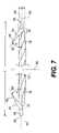
- FIG. 7is an enlarged side view of the embodiment of the stent illustrated in FIG. 6 ;
- FIG. 8is a top view of another embodiment of the stent illustrated in FIG. 1 , showing an alternative arrangement of the ends thereof.
- FIGS. 1–5A first embodiment of a stent 10 according to the invention is illustrated in FIGS. 1–5 .
- the stent 10is generally elongated and is sized to fit within a human's biliary or pancreatic duct. While the stent 10 of the present invention is intended for use in the common bile duct or pancreatic duct of a patient having a ductal occlusion or obstruction, the stent 10 may be used in other areas within the human body. Therefore, while the instant description focuses primarily on biliary and pancreatic ductal uses, the potential areas of use are not intended to be limited thereby.
- the stent 10may find application to various arterial and venous obstructions or occlusions. Moreover, the stent 10 may be employed in other channels within the human body. In addition, the stent 10 is not limited solely to use in humans.
- the stent 10preferably has a length L that is on the order of 12.0 cm and a cross-sectional width W that is on the order of 0.4 cm.
- the dimensions for the length L and width Ware exemplary only. It is contemplated that the length L of the stent 10 may be made longer or shorter depending upon the particular needs for a specific patient and the location where the stent 10 is emplaced. Similarly, the width W also may be increased or decreased to accommodate the specific needs of the patient and the location where the stent 10 is emplaced.
- the stent 10has a main or central body portion 12 that extends substantially along the entire length of the stent 10 , from one end 14 to the other end 16 .
- the stent 10has a plurality of rib-like wings 18 that extend radially from the main or central body portion 12 , substantially along the entire length L thereof. In this embodiment, the wings extend linearly from one end 14 to the other end 16 of the stent 10 .
- the rib-like wings 18present a smooth surface throughout their entire length on the central body portion 12 .
- the surfaces of the wings 18may be grooved, as described in U.S. Pat. Nos.
- the wings 18may be grooved along only a portion of their length but be smooth along another portion. Also, it is contemplated that some of the wings 18 may be grooved while others of the wings 18 present a smooth surface.
- FIG. 5provides a cross-sectional end view of one variant of the stent 10 shown in FIG. 1 . In FIG. 5 , only three wings 18 are employed, rather than the six wings 18 shown in FIG. 4 .
- the threeis the smallest number of wings 18 that may be employed to keep open the biliary or pancreatic duct.
- the largest number of wings 18has not been determined. However, it is believed that the addition of wings 18 beyond a maximum number will inhibit biliary or pancreatic flow. Therefore, there is an upper limit to the number of wings 18 that may be provided.
- Factors that will contribute to the maximum permissible number of wings 18include the shape of the wings 18 , their thicknesses, and their ability to be spaced around the central core, among others.
- the wings 18taper downwardly in thickness from their roots 20 to their radially outer edges 22 , as best illustrated in FIGS. 4 and 5 .
- Such a configurationprovides the wings 18 with sufficient lateral rigidity (i.e., rigidity to resist flexure from side-to-side as illustrated by double-headed arrow F in FIG. 4 ) to hold open the duct into which the stent 10 is placed.
- the wings 18may have a uniform width or thickness from their roots 20 to their radially outer edges 22 .
- the wings 18each have preferably a triangular cross-section. As indicated, this is but one possible construction. It is contemplated that each wing 18 alternatively may have a rectangular cross-section. In these two examples, it is contemplated that the surfaces of the wings 18 are planar. However, the surfaces may also be curved. For example, the wings may present an convex (or concave) parabolic surface, which may facilitate biological flow.
- the radially outer edges (or tips) 22 of the wings 18are shown with a “sharp” edge.
- the radially outer edges 22are formed by the intersection of the two planar surfaces that define the surface of the wings 18 .
- the “sharp” radially outer edges 22 of the wings 18will present any difficulties in the patient, especially because stent 10 is preferably made from a pliable plastic material, it is contemplated that the radially outer edges 22 of the wings 18 might present surfaces that irritate or inflame the interior surfaces of the biliary or pancreatic duct.
- the radial outer edges 22 of the wings 18preferably are rounded or blunted slightly to minimize discomfort to the patient and avoid laceration or inflammation of the biliary or pancreatic duct tissue.
- the surfaces 24 of the wings 18preferably are smooth for ease of manufacturing, i.e., to simplify making the extrusion dies used to make the stent 10 according to the invention.
- the wings 18preferably are uniformly or equiangularly spaced circumferentially around the main or central body portion 12 .
- a small-diameter guidewire lumen 26extends centrally along the entire length of the stent 10 , i.e., from one tip 28 of the stent 10 to the other tip 30 .
- the guidewire lumen 26is on the order of 1 mm in diameter and allows the stent 10 to be moved into proper position by being pushed along a guidewire, as is known in the art.
- a 1 mm diameter lumen 26is not the only size contemplated to fall within the scope of the present invention. To the contrary, any suitable diameter lumen 26 may be employed. Moreover, it may be desirable to have a lumen 26 with a sufficiently large diameter to permit some flow of bile (or other fluid) therethrough, even though such a construction is not preferred for the present invention. It is contemplated that most of (if not all) of the biological flow will occur between the wings 18 of the stent 10 and not through the central lumen 26 .
- the stent 10is illustrated as having a distinct central body portion 12 from which the wings 18 extend, with the guidewire lumen 26 positioned centrally within and extending longitudinally along the length of the main or central body portion 12 , it should be appreciated that it is not strictly necessary to have such a distinct main or central body portion 12 .
- the cross-section of the stent 10may be shaped more like an asterisk (*), with the wings 18 joined to each other and extending from a central juncture region of the asterisk and with the guidewire lumen 26 extending centrally along the length of that central juncture region.
- wings 18connect at their roots 20 to one another to form the central portion 12 and the lumen 26 .
- the stent 10 according to the inventionis preferably tapered and barbed at each end 14 , 16 .
- each end 14 , 16has a transition region 32 , 34 , where the radial height of the wings 18 decreases, and a smooth-surfaced, preferably conically tapered tip portion 36 , 38 .
- the smooth, conically tapered tip portions 36 , 38cooperate with the transition regions 32 , 34 to present a gradual transition from the tips 28 , 30 to the central body portion 12 of the stent 10 . This facilitates placement of the stent 10 in the patient's biliary or pancreatic tract, because, among other reasons, the gradual transition helps guide the stent 10 around the biliary or pancreatic obstruction.
- cantilevered securement barbs 40 , 42extend outwardly from the tip portions 36 , 38 and are angled relative to the central, longitudinal axis 44 of the stent 10 .
- the securement barbs 40 , 42are circumferentially positioned such that their tips 46 , 48 are longitudinally aligned with each other, as illustrated in FIG. 1 .
- theymay be circumferentially offset with respect to each other, as illustrated in FIG. 6 , for example.
- the securement barbs 40 , 42are cantilevered and angled in opposite directions.
- the tips 46 and 48 of the securement barbs 40 , 42are each positioned longitudinally closer to the longitudinal center 50 of the stent 10 than their respective barb roots 52 , 54 .
- the securement barbs 40 , 42form an angle ⁇ between a line 56 extending along the circumferential center of the radially outer surfaces of each of the securement barbs 40 , 42 and the central, longitudinal axis 44 that is less than or equal to about 90°.
- the angle of ⁇is less than or equal to about 75°, with an angle of about 65° being most preferred.
- the angle ⁇is the same at both ends 14 , 16 of the stent 10 . While the angle of ⁇ is preferably about 65°, it is contemplated that the angle ⁇ could be greater or smaller, depending on the surgeon's specific needs.
- the stent 10will resist migration in the biliary or pancreatic duct if the tips 46 , 48 of the securement barbs 40 , 42 are disposed at least slightly toward the centerline 50 of the stent 10 . Not only does this arrangement ensure that the stent 10 will remain securely emplaced with the biliary or pancreatic duct, but angling the securement barbs 40 , 42 in this manner facilitates placement within a patient, because the barbs 40 , 42 may be folded against the central portion 12 when the stent 10 is positioned in the biliary or pancreatic ducts using a cannula.
- the securement barbs 40 , 42were disposed such that their tips 46 , 48 were disposed at an angle ⁇ of greater than 90°, the tips 46 , 48 are believed to present a danger of perforating the biliary or pancreatic ducts when the stent 10 is positioned therein. It is, of course, believed possible to manufacture a stent 10 where the angle ⁇ is greater than 90° and such a stent is intended to be encompassed hereby.
- angle ⁇it is believed that an angle between about 60° and 90° is best to prevent (or at least minimize) migration of the stent 10 once positioned in the biliary or pancreatic duct. If the angle ⁇ is reduced to less than 60°, it is believed that securement barbs 40 , 42 will likely collapse against the main portion 12 of the stent 10 and, thereby, permit the stent 10 to migrate within the biliary or pancreatic duct.
- the angleis such that the securement barbs 40 , 42 can be compressed against the main portion 12 so as to be relatively flush against the radially outer edges 22 of the wings 18 as the stent 10 is being advanced along an implantation cannula used to implant the stent 10 .
- the securement barbs 40 , 42flex radially outwardly due to their inherent flexural resiliency to securely retain the stent 10 in the patient's body.
- the stent 10preferably is symmetric with respect to a plane passing through its longitudinal center 50 , perpendicularly to the central, longitudinal axis 44 .
- symmetryis not required to practice the invention.
- the stent 10may not be symmetrical about the plane disposed perpendicularly to the longitudinal axis 44 .
- there may be only one securement barb 40 , 42 at one end of the stent 10rather than a securement barb 40 , 42 at each end.
- only one endmay include a conically tapered tip portion 36 , 38 .
- the securement barbs 40 , 42wrap circumferentially approximately half way around the stent 10 , i.e., from one side to the other. Furthermore, as shown in FIG. 3 , the side-to-side width of the securement barbs 40 , 42 decreases from the barb roots 52 , 54 to the barb tips 46 , 48 , which gives the securement barbs 40 , 42 a somewhat teardrop or raindrop profile when the stent 10 is viewed end-on.
- the barb tips 46 , 48are preferably rounded, as viewed end-on.
- a blunted or rounded tip 46 , 48minimizes the possibility that the barb tips 46 , 48 will perforate the biliary or pancreatic duct.
- a blunted or rounded tip 46 , 48assures that stent 10 will not irritate the ductal tissue.
- the tips 46 , 48may have any of a number of shapes without departing from the scope of the invention.
- PellethaneTMa biocompatible thermoplastic polyurethane elastomer available from Dow Corning and that has been approved by the Food and Drug Administration for implantation
- PellethaneTMa biocompatible thermoplastic polyurethane elastomer available from Dow Corning and that has been approved by the Food and Drug Administration for implantation
- the extrusion apparatushas a longitudinally extending pin that protrudes through the extrusion opening in the extrusion die to form the guidewire lumen 26 .
- the extrusionis cut into lengths corresponding to the length of the final biliary stent product. Then, the transition regions 32 , 34 are formed, which preferably taper substantially to a somewhat blunted point.
- the tip portions 36 , 38which include the cantilevered securement barbs 40 , 42 , are manufactured separately. Then, the manufacture of the stent 10 is completed by attaching the tip portions 36 , 38 to the transition regions 32 , 34 .
- FIGS. 6 , 6 A, and 7A second embodiment 60 of a stent according to the invention is illustrated in FIGS. 6 , 6 A, and 7 .
- the stent 60differs from the first embodiment in that the wings 18 are helically configured. This helical configuration is obtained simply by rotating the extrusion die as the PellethaneTM is extruded. Because the parts and components of the stent 60 are otherwise identical to the parts and components of the stent 10 shown in FIGS. 1–5 , identical reference numbers are used to describe both embodiments and the second embodiment is not described further herein.
- the stent 10 or 60may include a pig-tail configuration 62 , 64 , in which one or both ends of the stent 10 , 60 is/are curled to a desired extent.
- This configurationmay be used instead of the securement barbs 40 , 42 .
- the pig tails 62 , 64are not shown with the securement barbs 40 , 42 .
- the pig tails 62 , 64may be used in conjunction with the securement barbs 40 , 42 .
- the pig tails 62 , 64increase the engagement pressure (the frictional engagement) between the stent 10 , 60 and the walls of the biliary or pancreatic duct.
- the embodiments of the stent 10 , 60 of the present inventionare described with securement barbs 40 , 42 disposed at the tip portions 36 , 38 .
- the barbs 40 , 42may be positioned between the tip portions 36 , 38 at locations on central portion 12 .
- a plurality of barbs 40 , 42may be employed to secure the stent 10 , 60 in the biliary or pancreatic duct.
- the securement barbs 40 , 42should be located such that the resiliency of the stent 10 , 60 biases the securement barbs 40 , 42 against the walls of the biliary or pancreatic duct.
- PellethaneTMis the preferred material for the manufacture of the stent 10 , 60 because of its flexural characteristics. Moreover, PellethaneTM is preferred because it has been approved by the Food and Drug Administration for implantation in human patients. As would be appreciated by those skilled in the art, however, other materials may be used instead of Pellethane.TM
Landscapes
- Health & Medical Sciences (AREA)
- Heart & Thoracic Surgery (AREA)
- Life Sciences & Earth Sciences (AREA)
- Cardiology (AREA)
- Oral & Maxillofacial Surgery (AREA)
- Transplantation (AREA)
- Engineering & Computer Science (AREA)
- Pulmonology (AREA)
- Biomedical Technology (AREA)
- Vascular Medicine (AREA)
- Gastroenterology & Hepatology (AREA)
- Animal Behavior & Ethology (AREA)
- General Health & Medical Sciences (AREA)
- Public Health (AREA)
- Veterinary Medicine (AREA)
- Media Introduction/Drainage Providing Device (AREA)
- Materials For Medical Uses (AREA)
Abstract
Description
Claims (36)
Priority Applications (4)
| Application Number | Priority Date | Filing Date | Title |
|---|---|---|---|
| US10/719,066US7338530B2 (en) | 2003-11-24 | 2003-11-24 | Stent |
| PCT/US2004/038629WO2005051237A1 (en) | 2003-11-24 | 2004-11-19 | Stent |
| EP04811357AEP1694245A1 (en) | 2003-11-24 | 2004-11-19 | Stent |
| CA002546855ACA2546855A1 (en) | 2003-11-24 | 2004-11-19 | Stent |
Applications Claiming Priority (1)
| Application Number | Priority Date | Filing Date | Title |
|---|---|---|---|
| US10/719,066US7338530B2 (en) | 2003-11-24 | 2003-11-24 | Stent |
Publications (2)
| Publication Number | Publication Date |
|---|---|
| US20050113933A1 US20050113933A1 (en) | 2005-05-26 |
| US7338530B2true US7338530B2 (en) | 2008-03-04 |
Family
ID=34591227
Family Applications (1)
| Application Number | Title | Priority Date | Filing Date |
|---|---|---|---|
| US10/719,066Expired - LifetimeUS7338530B2 (en) | 2003-11-24 | 2003-11-24 | Stent |
Country Status (4)
| Country | Link |
|---|---|
| US (1) | US7338530B2 (en) |
| EP (1) | EP1694245A1 (en) |
| CA (1) | CA2546855A1 (en) |
| WO (1) | WO2005051237A1 (en) |
Cited By (21)
| Publication number | Priority date | Publication date | Assignee | Title |
|---|---|---|---|---|
| US20080288082A1 (en)* | 2007-05-14 | 2008-11-20 | Travis Deal | Open lumen stent |
| US20100100170A1 (en)* | 2008-10-22 | 2010-04-22 | Boston Scientific Scimed, Inc. | Shape memory tubular stent with grooves |
| US20100256731A1 (en)* | 2009-04-02 | 2010-10-07 | Mangiardi Eric K | Stent |
| US20110054448A1 (en)* | 2009-08-28 | 2011-03-03 | Navilyst Medical, Inc. | Medical device containing catheter anchoring feature |
| US20110213453A1 (en)* | 2008-06-11 | 2011-09-01 | Eric Mangiardi | Stent |
| US20110230950A1 (en)* | 2008-09-16 | 2011-09-22 | Tracey Knapp | Stent |
| US20130066328A1 (en)* | 2011-04-07 | 2013-03-14 | Jai Singh | General uterine manipulator and system |
| US20130197536A1 (en)* | 2011-04-07 | 2013-08-01 | Jai Singh | General uterine manipulator and system |
| US8690749B1 (en) | 2009-11-02 | 2014-04-08 | Anthony Nunez | Wireless compressible heart pump |
| US20160081717A1 (en)* | 2011-04-07 | 2016-03-24 | Jai Singh | General uterine manipulator and system |
| US9415196B2 (en) | 2013-03-13 | 2016-08-16 | Boston Scientific Scimed, Inc. | Pancreatic stent drainage system |
| US9532837B2 (en) | 2012-04-20 | 2017-01-03 | Jiwan Steven Singh | Repositionable medical instrument support systems, devices, and methods |
| US20170151051A1 (en)* | 2014-06-26 | 2017-06-01 | S&G Biotech, Inc. | Stent having exterior path |
| US9839508B2 (en) | 2014-10-09 | 2017-12-12 | Boston Scientific Scimed, Inc. | Pancreatic stent with drainage feature |
| US9907584B2 (en) | 2008-06-11 | 2018-03-06 | Eventions, Llc | Orthopedic fastener device |
| US10117760B2 (en) | 2009-04-02 | 2018-11-06 | Q3 Medical Devices Limited | Stent |
| US10245165B2 (en) | 2009-04-02 | 2019-04-02 | Q3 Medical Devices Limited | Stent |
| US11207199B2 (en) | 2008-06-11 | 2021-12-28 | Q3 Medical Devices Limited | Stent with anti-migration devices |
| US11559412B2 (en) | 2019-01-07 | 2023-01-24 | Boston Scientific Scimed, Inc. | Stent with anti-migration feature |
| US11918496B2 (en) | 2020-12-02 | 2024-03-05 | Boston Scientific Scimed, Inc. | Stent with improved deployment characteristics |
| US12329665B2 (en) | 2020-09-29 | 2025-06-17 | Boston Scientific Scimed, Inc. | Stent with anti-migration features |
Families Citing this family (30)
| Publication number | Priority date | Publication date | Assignee | Title |
|---|---|---|---|---|
| US11890181B2 (en)* | 2002-07-22 | 2024-02-06 | Tmt Systems, Inc. | Percutaneous endovascular apparatus for repair of aneurysms and arterial blockages |
| AU2004240592A1 (en)* | 2003-05-15 | 2004-12-02 | Applied Medical Resources Corporation | Echogenic stent |
| US7632361B2 (en) | 2004-05-06 | 2009-12-15 | Tini Alloy Company | Single crystal shape memory alloy devices and methods |
| US20060118210A1 (en)* | 2004-10-04 | 2006-06-08 | Johnson A D | Portable energy storage devices and methods |
| US7763342B2 (en)* | 2005-03-31 | 2010-07-27 | Tini Alloy Company | Tear-resistant thin film methods of fabrication |
| US7540899B1 (en) | 2005-05-25 | 2009-06-02 | Tini Alloy Company | Shape memory alloy thin film, method of fabrication, and articles of manufacture |
| US20070246233A1 (en)* | 2006-04-04 | 2007-10-25 | Johnson A D | Thermal actuator for fire protection sprinkler head |
| US20080051911A1 (en)* | 2006-08-23 | 2008-02-28 | Wilson-Cook Medical Inc. | Stent with antimicrobial drainage lumen surface |
| US20080075557A1 (en)* | 2006-09-22 | 2008-03-27 | Johnson A David | Constant load bolt |
| US20080213062A1 (en)* | 2006-09-22 | 2008-09-04 | Tini Alloy Company | Constant load fastener |
| CA2665868C (en)* | 2006-10-16 | 2013-08-06 | Wilson-Cook Medical Inc. | Nonexpandable stent |
| WO2008133738A2 (en) | 2006-12-01 | 2008-11-06 | Tini Alloy Company | Method of alloying reactive components |
| US8584767B2 (en)* | 2007-01-25 | 2013-11-19 | Tini Alloy Company | Sprinkler valve with active actuation |
| WO2008092028A1 (en)* | 2007-01-25 | 2008-07-31 | Tini Alloy Company | Frangible shape memory alloy fire sprinkler valve actuator |
| US8007674B2 (en) | 2007-07-30 | 2011-08-30 | Tini Alloy Company | Method and devices for preventing restenosis in cardiovascular stents |
| US8556969B2 (en) | 2007-11-30 | 2013-10-15 | Ormco Corporation | Biocompatible copper-based single-crystal shape memory alloys |
| US7842143B2 (en)* | 2007-12-03 | 2010-11-30 | Tini Alloy Company | Hyperelastic shape setting devices and fabrication methods |
| US8382917B2 (en)* | 2007-12-03 | 2013-02-26 | Ormco Corporation | Hyperelastic shape setting devices and fabrication methods |
| US8287602B2 (en)* | 2007-12-12 | 2012-10-16 | Boston Scientific Scimed, Inc. | Urinary stent |
| AU2010261338B2 (en) | 2009-06-18 | 2015-08-20 | Cm Technologies, Inc. | Device for collecting fecal discharge in incontinent patients |
| US8603185B2 (en)* | 2010-03-11 | 2013-12-10 | Cook Medical Technologies Llc | Stent geometry |
| US9101453B2 (en)* | 2010-06-17 | 2015-08-11 | Greg Harold Albers | Urological repair apparatus and method |
| RU2458636C1 (en)* | 2011-03-02 | 2012-08-20 | Александр Сергеевич Толстокоров | Method of preventing bleeding from papillosphincterotomic wound after multi-stage endoscopic operation in case of choledocholithiasis |
| US10124197B2 (en) | 2012-08-31 | 2018-11-13 | TiNi Allot Company | Fire sprinkler valve actuator |
| US11040230B2 (en) | 2012-08-31 | 2021-06-22 | Tini Alloy Company | Fire sprinkler valve actuator |
| JP2016518162A (en)* | 2013-03-15 | 2016-06-23 | ボストン サイエンティフィック サイムド,インコーポレイテッドBoston Scientific Scimed,Inc. | Anti-migration stent coating |
| DE102013019890A1 (en)* | 2013-11-28 | 2015-05-28 | Bentley Innomed Gmbh | Medical implant |
| US20170014247A1 (en)* | 2015-07-15 | 2017-01-19 | Cook Medical Technologies Llc | Stent Anti-Migration Mechanism |
| CN109431650B (en)* | 2018-11-27 | 2021-08-17 | 深圳市先健畅通医疗有限公司 | Covered stent |
| KR102242357B1 (en)* | 2019-02-19 | 2021-04-20 | 서울대학교병원 | Stent for both biliary drainage and biopsy of biliary cancer using dual edge groove |
Citations (51)
| Publication number | Priority date | Publication date | Assignee | Title |
|---|---|---|---|---|
| DE88138C (en) | ||||
| GB105038A (en) | 1916-11-04 | 1917-03-29 | James Alexander Liddell | Improvements in Surgical Drainage Appliances. |
| GB189127A (en) | 1921-11-14 | 1923-05-03 | Manuel Herante Hantcher | Improvements in surgical drainage appliances |
| FR564832A (en) | 1923-03-29 | 1924-01-12 | Drains, probes, tubes and solid cylinders with screw threads made of rubber, gum or any other material suitable for replacing these two substances | |
| US3123077A (en)* | 1964-03-03 | Surgical suture | ||
| US3821956A (en) | 1973-08-14 | 1974-07-02 | D Gordhamer | Bovine teat dilator and medicament dispenser |
| DE7608671U1 (en) | 1976-03-20 | 1976-07-15 | Nessler, Reiner, Dr., 3320 Salzgitter | GUIDE PROBE FOR CATHETERIZATION OF THE VESSELS OF THE HUMAN BODY |
| US4307723A (en)* | 1978-04-07 | 1981-12-29 | Medical Engineering Corporation | Externally grooved ureteral stent |
| EP0059620A1 (en) | 1981-02-26 | 1982-09-08 | Larry Webster Blake | Wound drain catheter |
| US4350169A (en) | 1979-01-05 | 1982-09-21 | Medtronic, Inc. | Flexible tip stiffening stylet for use with body implantable lead |
| US4459318A (en) | 1981-11-09 | 1984-07-10 | American Hospital Supply Corporation | Method for forming a self-lubricating fill tube |
| EP0141006A1 (en) | 1983-09-16 | 1985-05-15 | Terumo Kabushiki Kaisha | Guide wire for catheter |
| US4521210A (en) | 1982-12-27 | 1985-06-04 | Wong Vernon G | Eye implant for relieving glaucoma, and device and method for use therewith |
| US4550447A (en) | 1983-08-03 | 1985-11-05 | Shiley Incorporated | Vascular graft prosthesis |
| US4677143A (en) | 1984-10-01 | 1987-06-30 | Baxter Travenol Laboratories, Inc. | Antimicrobial compositions |
| US4699611A (en) | 1985-04-19 | 1987-10-13 | C. R. Bard, Inc. | Biliary stent introducer |
| US4790810A (en)* | 1985-11-04 | 1988-12-13 | American Medical Systems, Inc. | Ureteral connector stent |
| US4795439A (en) | 1986-06-06 | 1989-01-03 | Edward Weck Incorporated | Spiral multi-lumen catheter |
| US4813925A (en) | 1987-04-21 | 1989-03-21 | Medical Engineering Corporation | Spiral ureteral stent |
| US4846791A (en) | 1988-09-02 | 1989-07-11 | Advanced Medical Technology & Development Corp. | Multi-lumen catheter |
| US4950228A (en)* | 1990-01-10 | 1990-08-21 | Knapp Jr Peter M | Ureteral stent |
| US4973301A (en) | 1989-07-11 | 1990-11-27 | Israel Nissenkorn | Catheter and method of using same |
| SU1641356A1 (en) | 1987-09-15 | 1991-04-15 | Куйбышевская Городская Больница N1 Им.Н.И.Пирогова | Drainage appliance |
| US5052998A (en)* | 1990-04-04 | 1991-10-01 | Zimmon David S | Indwelling stent and method of use |
| SU1715364A1 (en) | 1987-12-23 | 1992-02-28 | Slabinskij Valerij V | Drainage |
| SU1759431A1 (en) | 1989-01-12 | 1992-09-07 | Иркутский Государственный Медицинский Институт | Needle for introducing catheter |
| US5167614A (en) | 1991-10-29 | 1992-12-01 | Medical Engineering Corporation | Prostatic stent |
| US5176626A (en) | 1992-01-15 | 1993-01-05 | Wilson-Cook Medical, Inc. | Indwelling stent |
| US5246445A (en) | 1990-04-19 | 1993-09-21 | Instent Inc. | Device for the treatment of constricted ducts in human bodies |
| US5486191A (en) | 1994-02-02 | 1996-01-23 | John Hopkins University | Winged biliary stent |
| US5522881A (en)* | 1994-06-28 | 1996-06-04 | Meadox Medicals, Inc. | Implantable tubular prosthesis having integral cuffs |
| US5607464A (en) | 1991-02-28 | 1997-03-04 | Medtronic, Inc. | Prosthetic vascular graft with a pleated structure |
| US5628786A (en) | 1995-05-12 | 1997-05-13 | Impra, Inc. | Radially expandable vascular graft with resistance to longitudinal compression and method of making same |
| US5855597A (en)* | 1997-05-07 | 1999-01-05 | Iowa-India Investments Co. Limited | Stent valve and stent graft for percutaneous surgery |
| US5989207A (en)* | 1997-11-03 | 1999-11-23 | Hughes; Boyd R. | Double swirl stent |
| US6124523A (en) | 1995-03-10 | 2000-09-26 | Impra, Inc. | Encapsulated stent |
| US6132471A (en) | 1997-05-09 | 2000-10-17 | Advance Medical Concepts, Inc. | Stent for draining the pancreatic and biliary ducts and instrumentation for the placement thereof |
| JP2000316979A (en) | 1999-05-10 | 2000-11-21 | Fuji Systems Kk | Stent |
| US6214037B1 (en)* | 1999-03-18 | 2001-04-10 | Fossa Industries, Llc | Radially expanding stent |
| US6221060B1 (en)* | 1997-08-19 | 2001-04-24 | Abbeymoor Medical, Inc. | Urethral device with anchoring system |
| US20010041929A1 (en) | 1998-08-31 | 2001-11-15 | Oepen Randolph Von | Stent |
| US6322585B1 (en) | 1998-11-16 | 2001-11-27 | Endotex Interventional Systems, Inc. | Coiled-sheet stent-graft with slidable exo-skeleton |
| US6325820B1 (en) | 1998-11-16 | 2001-12-04 | Endotex Interventional Systems, Inc. | Coiled-sheet stent-graft with exo-skeleton |
| US6332892B1 (en)* | 1999-03-02 | 2001-12-25 | Scimed Life Systems, Inc. | Medical device with one or more helical coils |
| US20020032479A1 (en) | 1995-11-27 | 2002-03-14 | Schneider (Europe) Ag, A/K/A Schneider (Europe) Gmbh | Conical stent |
| US6383171B1 (en)* | 1999-10-12 | 2002-05-07 | Allan Will | Methods and devices for protecting a passageway in a body when advancing devices through the passageway |
| US20030093145A1 (en) | 2001-10-26 | 2003-05-15 | Cook Incorporated | Endoluminal graft |
| US20030100859A1 (en) | 2001-11-27 | 2003-05-29 | Scimed Life Systems, Inc. | Arterio-venous shunt graft |
| US20030120331A1 (en)* | 2001-12-20 | 2003-06-26 | Trivascular, Inc. | Advanced endovascular graft |
| US6692504B2 (en)* | 1999-05-17 | 2004-02-17 | Micrus Corporation | Clot retrieval device |
| US6767339B2 (en)* | 1997-12-12 | 2004-07-27 | Wilson-Cook Medical, Inc. | Body canal intrusion instrumentation having bidirectional coefficient of surface friction with body tissue |
Family Cites Families (1)
| Publication number | Priority date | Publication date | Assignee | Title |
|---|---|---|---|---|
| US4559318A (en)* | 1983-04-26 | 1985-12-17 | Phillips Petroleum Company | Supported vanadium dihalide-ether complex catalyst |
- 2003
- 2003-11-24USUS10/719,066patent/US7338530B2/ennot_activeExpired - Lifetime
- 2004
- 2004-11-19EPEP04811357Apatent/EP1694245A1/ennot_activeWithdrawn
- 2004-11-19WOPCT/US2004/038629patent/WO2005051237A1/ennot_activeApplication Discontinuation
- 2004-11-19CACA002546855Apatent/CA2546855A1/ennot_activeAbandoned
Patent Citations (55)
| Publication number | Priority date | Publication date | Assignee | Title |
|---|---|---|---|---|
| DE88138C (en) | ||||
| US3123077A (en)* | 1964-03-03 | Surgical suture | ||
| GB105038A (en) | 1916-11-04 | 1917-03-29 | James Alexander Liddell | Improvements in Surgical Drainage Appliances. |
| GB189127A (en) | 1921-11-14 | 1923-05-03 | Manuel Herante Hantcher | Improvements in surgical drainage appliances |
| FR564832A (en) | 1923-03-29 | 1924-01-12 | Drains, probes, tubes and solid cylinders with screw threads made of rubber, gum or any other material suitable for replacing these two substances | |
| US3821956A (en) | 1973-08-14 | 1974-07-02 | D Gordhamer | Bovine teat dilator and medicament dispenser |
| DE7608671U1 (en) | 1976-03-20 | 1976-07-15 | Nessler, Reiner, Dr., 3320 Salzgitter | GUIDE PROBE FOR CATHETERIZATION OF THE VESSELS OF THE HUMAN BODY |
| US4307723A (en)* | 1978-04-07 | 1981-12-29 | Medical Engineering Corporation | Externally grooved ureteral stent |
| US4350169A (en) | 1979-01-05 | 1982-09-21 | Medtronic, Inc. | Flexible tip stiffening stylet for use with body implantable lead |
| EP0059620A1 (en) | 1981-02-26 | 1982-09-08 | Larry Webster Blake | Wound drain catheter |
| US4459318A (en) | 1981-11-09 | 1984-07-10 | American Hospital Supply Corporation | Method for forming a self-lubricating fill tube |
| US4521210A (en) | 1982-12-27 | 1985-06-04 | Wong Vernon G | Eye implant for relieving glaucoma, and device and method for use therewith |
| US4550447A (en) | 1983-08-03 | 1985-11-05 | Shiley Incorporated | Vascular graft prosthesis |
| EP0141006A1 (en) | 1983-09-16 | 1985-05-15 | Terumo Kabushiki Kaisha | Guide wire for catheter |
| US4677143A (en) | 1984-10-01 | 1987-06-30 | Baxter Travenol Laboratories, Inc. | Antimicrobial compositions |
| US4699611A (en) | 1985-04-19 | 1987-10-13 | C. R. Bard, Inc. | Biliary stent introducer |
| US4790810A (en)* | 1985-11-04 | 1988-12-13 | American Medical Systems, Inc. | Ureteral connector stent |
| US4795439A (en) | 1986-06-06 | 1989-01-03 | Edward Weck Incorporated | Spiral multi-lumen catheter |
| US4813925A (en) | 1987-04-21 | 1989-03-21 | Medical Engineering Corporation | Spiral ureteral stent |
| SU1641356A1 (en) | 1987-09-15 | 1991-04-15 | Куйбышевская Городская Больница N1 Им.Н.И.Пирогова | Drainage appliance |
| SU1715364A1 (en) | 1987-12-23 | 1992-02-28 | Slabinskij Valerij V | Drainage |
| US4846791A (en) | 1988-09-02 | 1989-07-11 | Advanced Medical Technology & Development Corp. | Multi-lumen catheter |
| SU1759431A1 (en) | 1989-01-12 | 1992-09-07 | Иркутский Государственный Медицинский Институт | Needle for introducing catheter |
| US4973301A (en) | 1989-07-11 | 1990-11-27 | Israel Nissenkorn | Catheter and method of using same |
| US4950228A (en)* | 1990-01-10 | 1990-08-21 | Knapp Jr Peter M | Ureteral stent |
| US5052998A (en)* | 1990-04-04 | 1991-10-01 | Zimmon David S | Indwelling stent and method of use |
| US5246445A (en) | 1990-04-19 | 1993-09-21 | Instent Inc. | Device for the treatment of constricted ducts in human bodies |
| US5607464A (en) | 1991-02-28 | 1997-03-04 | Medtronic, Inc. | Prosthetic vascular graft with a pleated structure |
| US5653745A (en) | 1991-02-28 | 1997-08-05 | Medtronic, Inc. | Prosthetic vascular graft with a pleated structure |
| US5167614A (en) | 1991-10-29 | 1992-12-01 | Medical Engineering Corporation | Prostatic stent |
| US5176626A (en) | 1992-01-15 | 1993-01-05 | Wilson-Cook Medical, Inc. | Indwelling stent |
| US5486191A (en) | 1994-02-02 | 1996-01-23 | John Hopkins University | Winged biliary stent |
| US5776160A (en) | 1994-02-02 | 1998-07-07 | Pankaj Pasricha | Winged biliary stent |
| US5522881A (en)* | 1994-06-28 | 1996-06-04 | Meadox Medicals, Inc. | Implantable tubular prosthesis having integral cuffs |
| US6124523A (en) | 1995-03-10 | 2000-09-26 | Impra, Inc. | Encapsulated stent |
| US5628786A (en) | 1995-05-12 | 1997-05-13 | Impra, Inc. | Radially expandable vascular graft with resistance to longitudinal compression and method of making same |
| US20020032479A1 (en) | 1995-11-27 | 2002-03-14 | Schneider (Europe) Ag, A/K/A Schneider (Europe) Gmbh | Conical stent |
| US5855597A (en)* | 1997-05-07 | 1999-01-05 | Iowa-India Investments Co. Limited | Stent valve and stent graft for percutaneous surgery |
| US6132471A (en) | 1997-05-09 | 2000-10-17 | Advance Medical Concepts, Inc. | Stent for draining the pancreatic and biliary ducts and instrumentation for the placement thereof |
| US6221060B1 (en)* | 1997-08-19 | 2001-04-24 | Abbeymoor Medical, Inc. | Urethral device with anchoring system |
| US5989207A (en)* | 1997-11-03 | 1999-11-23 | Hughes; Boyd R. | Double swirl stent |
| US6767339B2 (en)* | 1997-12-12 | 2004-07-27 | Wilson-Cook Medical, Inc. | Body canal intrusion instrumentation having bidirectional coefficient of surface friction with body tissue |
| US20010041929A1 (en) | 1998-08-31 | 2001-11-15 | Oepen Randolph Von | Stent |
| US6322585B1 (en) | 1998-11-16 | 2001-11-27 | Endotex Interventional Systems, Inc. | Coiled-sheet stent-graft with slidable exo-skeleton |
| US6325820B1 (en) | 1998-11-16 | 2001-12-04 | Endotex Interventional Systems, Inc. | Coiled-sheet stent-graft with exo-skeleton |
| US20010051823A1 (en) | 1998-11-16 | 2001-12-13 | Endotex Interventional Systems, Inc. | Stretchable anti-buckling coiled-sheet stent |
| US20020038142A1 (en) | 1998-11-16 | 2002-03-28 | Endotex Interventional Systems, Inc. | Coiled-sheet stent-graft with slidable exo-skeleton |
| US6332892B1 (en)* | 1999-03-02 | 2001-12-25 | Scimed Life Systems, Inc. | Medical device with one or more helical coils |
| US6214037B1 (en)* | 1999-03-18 | 2001-04-10 | Fossa Industries, Llc | Radially expanding stent |
| JP2000316979A (en) | 1999-05-10 | 2000-11-21 | Fuji Systems Kk | Stent |
| US6692504B2 (en)* | 1999-05-17 | 2004-02-17 | Micrus Corporation | Clot retrieval device |
| US6383171B1 (en)* | 1999-10-12 | 2002-05-07 | Allan Will | Methods and devices for protecting a passageway in a body when advancing devices through the passageway |
| US20030093145A1 (en) | 2001-10-26 | 2003-05-15 | Cook Incorporated | Endoluminal graft |
| US20030100859A1 (en) | 2001-11-27 | 2003-05-29 | Scimed Life Systems, Inc. | Arterio-venous shunt graft |
| US20030120331A1 (en)* | 2001-12-20 | 2003-06-26 | Trivascular, Inc. | Advanced endovascular graft |
Cited By (53)
| Publication number | Priority date | Publication date | Assignee | Title |
|---|---|---|---|---|
| US10390928B2 (en) | 2007-05-14 | 2019-08-27 | Boston Scientific Scimed, Inc. | Open lumen stent |
| US20080288082A1 (en)* | 2007-05-14 | 2008-11-20 | Travis Deal | Open lumen stent |
| US8956419B2 (en)* | 2007-05-14 | 2015-02-17 | Boston Scientific Scimed, Inc. | Open lumen stent |
| US11207199B2 (en) | 2008-06-11 | 2021-12-28 | Q3 Medical Devices Limited | Stent with anti-migration devices |
| US20110213453A1 (en)* | 2008-06-11 | 2011-09-01 | Eric Mangiardi | Stent |
| US9907584B2 (en) | 2008-06-11 | 2018-03-06 | Eventions, Llc | Orthopedic fastener device |
| US8398705B2 (en)* | 2008-06-11 | 2013-03-19 | Eric Mangiardi | Stent |
| US10022165B2 (en) | 2008-06-11 | 2018-07-17 | Eventions, Llc | Orthopedic fastener device |
| US10022164B2 (en) | 2008-06-11 | 2018-07-17 | Eventions, Llc | Orthopedic fastener device |
| US20110230950A1 (en)* | 2008-09-16 | 2011-09-22 | Tracey Knapp | Stent |
| US8764847B2 (en)* | 2008-09-16 | 2014-07-01 | C. R. Bard, Inc. | Stent |
| US20100100170A1 (en)* | 2008-10-22 | 2010-04-22 | Boston Scientific Scimed, Inc. | Shape memory tubular stent with grooves |
| US9980806B2 (en) | 2008-10-22 | 2018-05-29 | Boston Scientific Scimed, Inc. | Shape memory tubular stent with grooves |
| US20210128328A1 (en)* | 2009-04-02 | 2021-05-06 | Q3 Medical Devices Limited | Stent |
| US10779966B2 (en) | 2009-04-02 | 2020-09-22 | Q3 Medical Devices Limited | Stent |
| US12343269B2 (en)* | 2009-04-02 | 2025-07-01 | Q3 Medical Devices Limited | Stent |
| US12268618B2 (en)* | 2009-04-02 | 2025-04-08 | Q3 Medical Devices Limited | Stent |
| US20230263647A1 (en)* | 2009-04-02 | 2023-08-24 | Q3 Medical Devicess Limited | Stent |
| US11596532B2 (en)* | 2009-04-02 | 2023-03-07 | Q3 Medical Devices Limited | Stent |
| US11224528B2 (en) | 2009-04-02 | 2022-01-18 | Q3 Medical Devices Limited | Stent |
| US20100256731A1 (en)* | 2009-04-02 | 2010-10-07 | Mangiardi Eric K | Stent |
| US11173058B2 (en) | 2009-04-02 | 2021-11-16 | Q3 Medical Devices Limited | Stent |
| US10245165B2 (en) | 2009-04-02 | 2019-04-02 | Q3 Medical Devices Limited | Stent |
| US10932925B2 (en) | 2009-04-02 | 2021-03-02 | Q3 Medical Devices Limited | Stent |
| US20200390572A1 (en)* | 2009-04-02 | 2020-12-17 | Q3 Medical Devices Limited | Stent |
| US10201440B2 (en) | 2009-04-02 | 2019-02-12 | Q3 Medical Devices Limited | Stent |
| US10531969B2 (en) | 2009-04-02 | 2020-01-14 | Q3 Medical Devices Limited | Stent |
| US10117760B2 (en) | 2009-04-02 | 2018-11-06 | Q3 Medical Devices Limited | Stent |
| US10583019B2 (en) | 2009-04-02 | 2020-03-10 | Q3 Medical Devices Limited | Stent |
| US20110054448A1 (en)* | 2009-08-28 | 2011-03-03 | Navilyst Medical, Inc. | Medical device containing catheter anchoring feature |
| US8690749B1 (en) | 2009-11-02 | 2014-04-08 | Anthony Nunez | Wireless compressible heart pump |
| US9987042B2 (en)* | 2011-04-07 | 2018-06-05 | Jai Singh | General uterine manipulator and system |
| US20160081717A1 (en)* | 2011-04-07 | 2016-03-24 | Jai Singh | General uterine manipulator and system |
| US20130066328A1 (en)* | 2011-04-07 | 2013-03-14 | Jai Singh | General uterine manipulator and system |
| US9451985B2 (en) | 2011-04-07 | 2016-09-27 | Jiwan Steven Singh | General uterine manipulator and system |
| US20130197536A1 (en)* | 2011-04-07 | 2013-08-01 | Jai Singh | General uterine manipulator and system |
| US10792072B2 (en) | 2011-04-07 | 2020-10-06 | Jai Singh | General uterine manipulator and system |
| US9101390B2 (en)* | 2011-04-07 | 2015-08-11 | Jai Singh | General uterine manipulator and system |
| US9974567B2 (en) | 2011-04-07 | 2018-05-22 | Jiwan Steven Singh | General uterine manipulator and system |
| US20150012009A1 (en)* | 2011-04-07 | 2015-01-08 | Jai Singh | General uterine manipulator and system |
| US10004569B2 (en) | 2012-04-20 | 2018-06-26 | Jiwan Steven Singh | Repositionable medical instrument support systems, devices, and methods |
| US9532837B2 (en) | 2012-04-20 | 2017-01-03 | Jiwan Steven Singh | Repositionable medical instrument support systems, devices, and methods |
| US9415196B2 (en) | 2013-03-13 | 2016-08-16 | Boston Scientific Scimed, Inc. | Pancreatic stent drainage system |
| US20170151051A1 (en)* | 2014-06-26 | 2017-06-01 | S&G Biotech, Inc. | Stent having exterior path |
| US10130460B2 (en)* | 2014-06-26 | 2018-11-20 | S&G Biotech, Inc. | Stent having exterior path |
| US9839508B2 (en) | 2014-10-09 | 2017-12-12 | Boston Scientific Scimed, Inc. | Pancreatic stent with drainage feature |
| US12178694B2 (en) | 2014-10-09 | 2024-12-31 | Boston Scientific Scimed, Inc. | Pancreatic stent with drainage feature |
| US12257140B2 (en) | 2014-10-09 | 2025-03-25 | Boston Scientific Scimed, Inc. | Pancreatic stent with drainage feature |
| US11376111B2 (en) | 2014-10-09 | 2022-07-05 | Boston Scientific Scimed, Inc. | Pancreatic stent with drainage feature |
| US10500035B2 (en) | 2014-10-09 | 2019-12-10 | Boston Scientific Scimed, Inc. | Pancreatic stent with drainage feature |
| US11559412B2 (en) | 2019-01-07 | 2023-01-24 | Boston Scientific Scimed, Inc. | Stent with anti-migration feature |
| US12329665B2 (en) | 2020-09-29 | 2025-06-17 | Boston Scientific Scimed, Inc. | Stent with anti-migration features |
| US11918496B2 (en) | 2020-12-02 | 2024-03-05 | Boston Scientific Scimed, Inc. | Stent with improved deployment characteristics |
Also Published As
| Publication number | Publication date |
|---|---|
| EP1694245A1 (en) | 2006-08-30 |
| CA2546855A1 (en) | 2005-06-09 |
| WO2005051237A1 (en) | 2005-06-09 |
| US20050113933A1 (en) | 2005-05-26 |
Similar Documents
| Publication | Publication Date | Title |
|---|---|---|
| US7338530B2 (en) | Stent | |
| US20240189089A1 (en) | Biliary Stents and Methods | |
| EP3634259B1 (en) | Flow control stent | |
| US6656146B1 (en) | Medical device with tail(s) | |
| US5902282A (en) | Step-down catheter | |
| US6893424B2 (en) | Drain catheters | |
| JP4495736B2 (en) | Ureteral stent with a small bladder tail | |
| US8511310B2 (en) | Therapeutic medical appliance delivery and method of use | |
| WO2001091668A1 (en) | Ureteral stent | |
| JPS63214264A (en) | Method and apparatus for treating prostatic hypertrophy | |
| EP2566561B1 (en) | Improved catheter design for use in treating pleural diseases | |
| US20250009495A1 (en) | Biliary stent and delivery device | |
| US11529497B1 (en) | Centering device for a catheter | |
| CN116456941A (en) | Stent device and method for increasing patency of body opening | |
| US20100010478A1 (en) | Intraurethral catheter | |
| KR102570636B1 (en) | Indwelling catheter for reducing surface friction and pain | |
| EP4599777A1 (en) | Prostatic urethra implant for treating prostate enlargement | |
| CN119488384A (en) | Cutting Tubes, Sheaths, and Delivery Systems |
Legal Events
| Date | Code | Title | Description |
|---|---|---|---|
| AS | Assignment | Owner name:CHECKMED SYSTEMS, INC., PENNSYLVANIA Free format text:ASSIGNMENT OF ASSIGNORS INTEREST;ASSIGNORS:CARTER, FRANK;KALLOO, ANTHONY;PASRICHA, P. JAY;REEL/FRAME:015068/0048;SIGNING DATES FROM 20040303 TO 20040304 | |
| STCF | Information on status: patent grant | Free format text:PATENTED CASE | |
| FEPP | Fee payment procedure | Free format text:PAYOR NUMBER ASSIGNED (ORIGINAL EVENT CODE: ASPN); ENTITY STATUS OF PATENT OWNER: SMALL ENTITY | |
| FPAY | Fee payment | Year of fee payment:4 | |
| FPAY | Fee payment | Year of fee payment:8 | |
| MAFP | Maintenance fee payment | Free format text:PAYMENT OF MAINTENANCE FEE, 12TH YR, SMALL ENTITY (ORIGINAL EVENT CODE: M2553); ENTITY STATUS OF PATENT OWNER: SMALL ENTITY Year of fee payment:12 | |
| AS | Assignment | Owner name:JPMORGAN CHASE BANK, N.A., ILLINOIS Free format text:PATENT SECURITY AGREEMENT;ASSIGNOR:GI SUPPLY, INC.;REEL/FRAME:060560/0880 Effective date:20220608 | |
| AS | Assignment | Owner name:GI SUPPLY, INC., PENNSYLVANIA Free format text:RELEASE BY SECURED PARTY;ASSIGNOR:JPMORGAN CHASE BANK, N.A., AS ADMINISTRATIVE AGENT;REEL/FRAME:066984/0479 Effective date:20240402 |