US7338528B2 - Humeral stem with anatomical location of taper access for fixation of humeral head - Google Patents
Humeral stem with anatomical location of taper access for fixation of humeral headDownload PDFInfo
- Publication number
- US7338528B2 US7338528B2US10/358,079US35807903AUS7338528B2US 7338528 B2US7338528 B2US 7338528B2US 35807903 AUS35807903 AUS 35807903AUS 7338528 B2US7338528 B2US 7338528B2
- Authority
- US
- United States
- Prior art keywords
- head
- stem
- proximal end
- coupling mechanism
- axis
- Prior art date
- Legal status (The legal status is an assumption and is not a legal conclusion. Google has not performed a legal analysis and makes no representation as to the accuracy of the status listed.)
- Expired - Lifetime
Links
- 210000004095humeral headAnatomy0.000titleabstractdescription10
- 230000008878couplingEffects0.000claimsdescription33
- 238000010168coupling processMethods0.000claimsdescription33
- 238000005859coupling reactionMethods0.000claimsdescription33
- 230000007246mechanismEffects0.000claimsdescription16
- 210000002758humerusAnatomy0.000claimsdescription10
- 238000001356surgical procedureMethods0.000abstractdescription2
- 241001653121GlenoidesSpecies0.000description11
- 238000011882arthroplastyMethods0.000description8
- 238000000034methodMethods0.000description6
- 210000000323shoulder jointAnatomy0.000description6
- 229910000684Cobalt-chromeInorganic materials0.000description3
- 239000000560biocompatible materialSubstances0.000description3
- 230000008859changeEffects0.000description3
- 239000010952cobalt-chromeSubstances0.000description3
- 239000007943implantSubstances0.000description3
- RTAQQCXQSZGOHL-UHFFFAOYSA-NTitaniumChemical compound[Ti]RTAQQCXQSZGOHL-UHFFFAOYSA-N0.000description2
- 210000000988bone and boneAnatomy0.000description2
- 239000000919ceramicSubstances0.000description2
- 230000005786degenerative changesEffects0.000description2
- 238000002513implantationMethods0.000description2
- 239000000463materialSubstances0.000description2
- 230000013011matingEffects0.000description2
- 238000012986modificationMethods0.000description2
- 230000004048modificationEffects0.000description2
- 239000010935stainless steelSubstances0.000description2
- 229910001220stainless steelInorganic materials0.000description2
- 239000010936titaniumSubstances0.000description2
- 229910052719titaniumInorganic materials0.000description2
- 230000003044adaptive effectEffects0.000description1
- 239000011248coating agentSubstances0.000description1
- 238000000576coating methodMethods0.000description1
- 210000004394hip jointAnatomy0.000description1
- 230000002427irreversible effectEffects0.000description1
- 210000001503jointAnatomy0.000description1
- 229910052751metalInorganic materials0.000description1
- 239000002184metalSubstances0.000description1
- 210000001991scapulaAnatomy0.000description1
- 239000007921spraySubstances0.000description1
Images


Classifications
- A—HUMAN NECESSITIES
- A61—MEDICAL OR VETERINARY SCIENCE; HYGIENE
- A61F—FILTERS IMPLANTABLE INTO BLOOD VESSELS; PROSTHESES; DEVICES PROVIDING PATENCY TO, OR PREVENTING COLLAPSING OF, TUBULAR STRUCTURES OF THE BODY, e.g. STENTS; ORTHOPAEDIC, NURSING OR CONTRACEPTIVE DEVICES; FOMENTATION; TREATMENT OR PROTECTION OF EYES OR EARS; BANDAGES, DRESSINGS OR ABSORBENT PADS; FIRST-AID KITS
- A61F2/00—Filters implantable into blood vessels; Prostheses, i.e. artificial substitutes or replacements for parts of the body; Appliances for connecting them with the body; Devices providing patency to, or preventing collapsing of, tubular structures of the body, e.g. stents
- A61F2/02—Prostheses implantable into the body
- A61F2/30—Joints
- A61F2/40—Joints for shoulders
- A61F2/4014—Humeral heads or necks; Connections of endoprosthetic heads or necks to endoprosthetic humeral shafts
- A—HUMAN NECESSITIES
- A61—MEDICAL OR VETERINARY SCIENCE; HYGIENE
- A61F—FILTERS IMPLANTABLE INTO BLOOD VESSELS; PROSTHESES; DEVICES PROVIDING PATENCY TO, OR PREVENTING COLLAPSING OF, TUBULAR STRUCTURES OF THE BODY, e.g. STENTS; ORTHOPAEDIC, NURSING OR CONTRACEPTIVE DEVICES; FOMENTATION; TREATMENT OR PROTECTION OF EYES OR EARS; BANDAGES, DRESSINGS OR ABSORBENT PADS; FIRST-AID KITS
- A61F2/00—Filters implantable into blood vessels; Prostheses, i.e. artificial substitutes or replacements for parts of the body; Appliances for connecting them with the body; Devices providing patency to, or preventing collapsing of, tubular structures of the body, e.g. stents
- A61F2/02—Prostheses implantable into the body
- A61F2/30—Joints
- A61F2/40—Joints for shoulders
- A61F2/4059—Humeral shafts
- A—HUMAN NECESSITIES
- A61—MEDICAL OR VETERINARY SCIENCE; HYGIENE
- A61F—FILTERS IMPLANTABLE INTO BLOOD VESSELS; PROSTHESES; DEVICES PROVIDING PATENCY TO, OR PREVENTING COLLAPSING OF, TUBULAR STRUCTURES OF THE BODY, e.g. STENTS; ORTHOPAEDIC, NURSING OR CONTRACEPTIVE DEVICES; FOMENTATION; TREATMENT OR PROTECTION OF EYES OR EARS; BANDAGES, DRESSINGS OR ABSORBENT PADS; FIRST-AID KITS
- A61F2/00—Filters implantable into blood vessels; Prostheses, i.e. artificial substitutes or replacements for parts of the body; Appliances for connecting them with the body; Devices providing patency to, or preventing collapsing of, tubular structures of the body, e.g. stents
- A61F2/02—Prostheses implantable into the body
- A61F2/30—Joints
- A61F2002/30001—Additional features of subject-matter classified in A61F2/28, A61F2/30 and subgroups thereof
- A61F2002/30108—Shapes
- A61F2002/30199—Three-dimensional shapes
- A61F2002/30242—Three-dimensional shapes spherical
- A61F2002/30245—Partial spheres
- A—HUMAN NECESSITIES
- A61—MEDICAL OR VETERINARY SCIENCE; HYGIENE
- A61F—FILTERS IMPLANTABLE INTO BLOOD VESSELS; PROSTHESES; DEVICES PROVIDING PATENCY TO, OR PREVENTING COLLAPSING OF, TUBULAR STRUCTURES OF THE BODY, e.g. STENTS; ORTHOPAEDIC, NURSING OR CONTRACEPTIVE DEVICES; FOMENTATION; TREATMENT OR PROTECTION OF EYES OR EARS; BANDAGES, DRESSINGS OR ABSORBENT PADS; FIRST-AID KITS
- A61F2/00—Filters implantable into blood vessels; Prostheses, i.e. artificial substitutes or replacements for parts of the body; Appliances for connecting them with the body; Devices providing patency to, or preventing collapsing of, tubular structures of the body, e.g. stents
- A61F2/02—Prostheses implantable into the body
- A61F2/30—Joints
- A61F2002/30001—Additional features of subject-matter classified in A61F2/28, A61F2/30 and subgroups thereof
- A61F2002/30316—The prosthesis having different structural features at different locations within the same prosthesis; Connections between prosthetic parts; Special structural features of bone or joint prostheses not otherwise provided for
- A61F2002/30329—Connections or couplings between prosthetic parts, e.g. between modular parts; Connecting elements
- A61F2002/30331—Connections or couplings between prosthetic parts, e.g. between modular parts; Connecting elements made by longitudinally pushing a protrusion into a complementarily-shaped recess, e.g. held by friction fit
- A61F2002/30332—Conically- or frustoconically-shaped protrusion and recess
- A—HUMAN NECESSITIES
- A61—MEDICAL OR VETERINARY SCIENCE; HYGIENE
- A61F—FILTERS IMPLANTABLE INTO BLOOD VESSELS; PROSTHESES; DEVICES PROVIDING PATENCY TO, OR PREVENTING COLLAPSING OF, TUBULAR STRUCTURES OF THE BODY, e.g. STENTS; ORTHOPAEDIC, NURSING OR CONTRACEPTIVE DEVICES; FOMENTATION; TREATMENT OR PROTECTION OF EYES OR EARS; BANDAGES, DRESSINGS OR ABSORBENT PADS; FIRST-AID KITS
- A61F2/00—Filters implantable into blood vessels; Prostheses, i.e. artificial substitutes or replacements for parts of the body; Appliances for connecting them with the body; Devices providing patency to, or preventing collapsing of, tubular structures of the body, e.g. stents
- A61F2/02—Prostheses implantable into the body
- A61F2/30—Joints
- A61F2002/30001—Additional features of subject-matter classified in A61F2/28, A61F2/30 and subgroups thereof
- A61F2002/30316—The prosthesis having different structural features at different locations within the same prosthesis; Connections between prosthetic parts; Special structural features of bone or joint prostheses not otherwise provided for
- A61F2002/30329—Connections or couplings between prosthetic parts, e.g. between modular parts; Connecting elements
- A61F2002/30405—Connections or couplings between prosthetic parts, e.g. between modular parts; Connecting elements made by screwing complementary threads machined on the parts themselves
- A—HUMAN NECESSITIES
- A61—MEDICAL OR VETERINARY SCIENCE; HYGIENE
- A61F—FILTERS IMPLANTABLE INTO BLOOD VESSELS; PROSTHESES; DEVICES PROVIDING PATENCY TO, OR PREVENTING COLLAPSING OF, TUBULAR STRUCTURES OF THE BODY, e.g. STENTS; ORTHOPAEDIC, NURSING OR CONTRACEPTIVE DEVICES; FOMENTATION; TREATMENT OR PROTECTION OF EYES OR EARS; BANDAGES, DRESSINGS OR ABSORBENT PADS; FIRST-AID KITS
- A61F2/00—Filters implantable into blood vessels; Prostheses, i.e. artificial substitutes or replacements for parts of the body; Appliances for connecting them with the body; Devices providing patency to, or preventing collapsing of, tubular structures of the body, e.g. stents
- A61F2/02—Prostheses implantable into the body
- A61F2/30—Joints
- A61F2002/30001—Additional features of subject-matter classified in A61F2/28, A61F2/30 and subgroups thereof
- A61F2002/30316—The prosthesis having different structural features at different locations within the same prosthesis; Connections between prosthetic parts; Special structural features of bone or joint prostheses not otherwise provided for
- A61F2002/30535—Special structural features of bone or joint prostheses not otherwise provided for
- A61F2002/30604—Special structural features of bone or joint prostheses not otherwise provided for modular
- A61F2002/30616—Sets comprising a plurality of prosthetic parts of different sizes or orientations
- A—HUMAN NECESSITIES
- A61—MEDICAL OR VETERINARY SCIENCE; HYGIENE
- A61F—FILTERS IMPLANTABLE INTO BLOOD VESSELS; PROSTHESES; DEVICES PROVIDING PATENCY TO, OR PREVENTING COLLAPSING OF, TUBULAR STRUCTURES OF THE BODY, e.g. STENTS; ORTHOPAEDIC, NURSING OR CONTRACEPTIVE DEVICES; FOMENTATION; TREATMENT OR PROTECTION OF EYES OR EARS; BANDAGES, DRESSINGS OR ABSORBENT PADS; FIRST-AID KITS
- A61F2/00—Filters implantable into blood vessels; Prostheses, i.e. artificial substitutes or replacements for parts of the body; Appliances for connecting them with the body; Devices providing patency to, or preventing collapsing of, tubular structures of the body, e.g. stents
- A61F2/02—Prostheses implantable into the body
- A61F2/30—Joints
- A61F2/40—Joints for shoulders
- A61F2/4014—Humeral heads or necks; Connections of endoprosthetic heads or necks to endoprosthetic humeral shafts
- A61F2002/4029—Necks
- A61F2002/4033—Necks with an integral complete or partial peripheral collar at its base
- A—HUMAN NECESSITIES
- A61—MEDICAL OR VETERINARY SCIENCE; HYGIENE
- A61F—FILTERS IMPLANTABLE INTO BLOOD VESSELS; PROSTHESES; DEVICES PROVIDING PATENCY TO, OR PREVENTING COLLAPSING OF, TUBULAR STRUCTURES OF THE BODY, e.g. STENTS; ORTHOPAEDIC, NURSING OR CONTRACEPTIVE DEVICES; FOMENTATION; TREATMENT OR PROTECTION OF EYES OR EARS; BANDAGES, DRESSINGS OR ABSORBENT PADS; FIRST-AID KITS
- A61F2/00—Filters implantable into blood vessels; Prostheses, i.e. artificial substitutes or replacements for parts of the body; Appliances for connecting them with the body; Devices providing patency to, or preventing collapsing of, tubular structures of the body, e.g. stents
- A61F2/02—Prostheses implantable into the body
- A61F2/30—Joints
- A61F2/40—Joints for shoulders
- A61F2/4014—Humeral heads or necks; Connections of endoprosthetic heads or necks to endoprosthetic humeral shafts
- A61F2002/4037—Connections of heads to necks
- A—HUMAN NECESSITIES
- A61—MEDICAL OR VETERINARY SCIENCE; HYGIENE
- A61F—FILTERS IMPLANTABLE INTO BLOOD VESSELS; PROSTHESES; DEVICES PROVIDING PATENCY TO, OR PREVENTING COLLAPSING OF, TUBULAR STRUCTURES OF THE BODY, e.g. STENTS; ORTHOPAEDIC, NURSING OR CONTRACEPTIVE DEVICES; FOMENTATION; TREATMENT OR PROTECTION OF EYES OR EARS; BANDAGES, DRESSINGS OR ABSORBENT PADS; FIRST-AID KITS
- A61F2/00—Filters implantable into blood vessels; Prostheses, i.e. artificial substitutes or replacements for parts of the body; Appliances for connecting them with the body; Devices providing patency to, or preventing collapsing of, tubular structures of the body, e.g. stents
- A61F2/02—Prostheses implantable into the body
- A61F2/30—Joints
- A61F2/40—Joints for shoulders
- A61F2/4014—Humeral heads or necks; Connections of endoprosthetic heads or necks to endoprosthetic humeral shafts
- A61F2002/4044—Connections of necks to shafts
- A—HUMAN NECESSITIES
- A61—MEDICAL OR VETERINARY SCIENCE; HYGIENE
- A61F—FILTERS IMPLANTABLE INTO BLOOD VESSELS; PROSTHESES; DEVICES PROVIDING PATENCY TO, OR PREVENTING COLLAPSING OF, TUBULAR STRUCTURES OF THE BODY, e.g. STENTS; ORTHOPAEDIC, NURSING OR CONTRACEPTIVE DEVICES; FOMENTATION; TREATMENT OR PROTECTION OF EYES OR EARS; BANDAGES, DRESSINGS OR ABSORBENT PADS; FIRST-AID KITS
- A61F2/00—Filters implantable into blood vessels; Prostheses, i.e. artificial substitutes or replacements for parts of the body; Appliances for connecting them with the body; Devices providing patency to, or preventing collapsing of, tubular structures of the body, e.g. stents
- A61F2/02—Prostheses implantable into the body
- A61F2/30—Joints
- A61F2/40—Joints for shoulders
- A61F2/4014—Humeral heads or necks; Connections of endoprosthetic heads or necks to endoprosthetic humeral shafts
- A61F2002/4051—Connections of heads directly to shafts
- A—HUMAN NECESSITIES
- A61—MEDICAL OR VETERINARY SCIENCE; HYGIENE
- A61F—FILTERS IMPLANTABLE INTO BLOOD VESSELS; PROSTHESES; DEVICES PROVIDING PATENCY TO, OR PREVENTING COLLAPSING OF, TUBULAR STRUCTURES OF THE BODY, e.g. STENTS; ORTHOPAEDIC, NURSING OR CONTRACEPTIVE DEVICES; FOMENTATION; TREATMENT OR PROTECTION OF EYES OR EARS; BANDAGES, DRESSINGS OR ABSORBENT PADS; FIRST-AID KITS
- A61F2220/00—Fixations or connections for prostheses classified in groups A61F2/00 - A61F2/26 or A61F2/82 or A61F9/00 or A61F11/00 or subgroups thereof
- A61F2220/0025—Connections or couplings between prosthetic parts, e.g. between modular parts; Connecting elements
- A61F2220/0033—Connections or couplings between prosthetic parts, e.g. between modular parts; Connecting elements made by longitudinally pushing a protrusion into a complementary-shaped recess, e.g. held by friction fit
- A—HUMAN NECESSITIES
- A61—MEDICAL OR VETERINARY SCIENCE; HYGIENE
- A61F—FILTERS IMPLANTABLE INTO BLOOD VESSELS; PROSTHESES; DEVICES PROVIDING PATENCY TO, OR PREVENTING COLLAPSING OF, TUBULAR STRUCTURES OF THE BODY, e.g. STENTS; ORTHOPAEDIC, NURSING OR CONTRACEPTIVE DEVICES; FOMENTATION; TREATMENT OR PROTECTION OF EYES OR EARS; BANDAGES, DRESSINGS OR ABSORBENT PADS; FIRST-AID KITS
- A61F2230/00—Geometry of prostheses classified in groups A61F2/00 - A61F2/26 or A61F2/82 or A61F9/00 or A61F11/00 or subgroups thereof
- A61F2230/0063—Three-dimensional shapes
- A61F2230/0071—Three-dimensional shapes spherical
- A—HUMAN NECESSITIES
- A61—MEDICAL OR VETERINARY SCIENCE; HYGIENE
- A61F—FILTERS IMPLANTABLE INTO BLOOD VESSELS; PROSTHESES; DEVICES PROVIDING PATENCY TO, OR PREVENTING COLLAPSING OF, TUBULAR STRUCTURES OF THE BODY, e.g. STENTS; ORTHOPAEDIC, NURSING OR CONTRACEPTIVE DEVICES; FOMENTATION; TREATMENT OR PROTECTION OF EYES OR EARS; BANDAGES, DRESSINGS OR ABSORBENT PADS; FIRST-AID KITS
- A61F2310/00—Prostheses classified in A61F2/28 or A61F2/30 - A61F2/44 being constructed from or coated with a particular material
- A61F2310/00005—The prosthesis being constructed from a particular material
- A61F2310/00011—Metals or alloys
- A61F2310/00017—Iron- or Fe-based alloys, e.g. stainless steel
- A—HUMAN NECESSITIES
- A61—MEDICAL OR VETERINARY SCIENCE; HYGIENE
- A61F—FILTERS IMPLANTABLE INTO BLOOD VESSELS; PROSTHESES; DEVICES PROVIDING PATENCY TO, OR PREVENTING COLLAPSING OF, TUBULAR STRUCTURES OF THE BODY, e.g. STENTS; ORTHOPAEDIC, NURSING OR CONTRACEPTIVE DEVICES; FOMENTATION; TREATMENT OR PROTECTION OF EYES OR EARS; BANDAGES, DRESSINGS OR ABSORBENT PADS; FIRST-AID KITS
- A61F2310/00—Prostheses classified in A61F2/28 or A61F2/30 - A61F2/44 being constructed from or coated with a particular material
- A61F2310/00005—The prosthesis being constructed from a particular material
- A61F2310/00011—Metals or alloys
- A61F2310/00023—Titanium or titanium-based alloys, e.g. Ti-Ni alloys
- A—HUMAN NECESSITIES
- A61—MEDICAL OR VETERINARY SCIENCE; HYGIENE
- A61F—FILTERS IMPLANTABLE INTO BLOOD VESSELS; PROSTHESES; DEVICES PROVIDING PATENCY TO, OR PREVENTING COLLAPSING OF, TUBULAR STRUCTURES OF THE BODY, e.g. STENTS; ORTHOPAEDIC, NURSING OR CONTRACEPTIVE DEVICES; FOMENTATION; TREATMENT OR PROTECTION OF EYES OR EARS; BANDAGES, DRESSINGS OR ABSORBENT PADS; FIRST-AID KITS
- A61F2310/00—Prostheses classified in A61F2/28 or A61F2/30 - A61F2/44 being constructed from or coated with a particular material
- A61F2310/00005—The prosthesis being constructed from a particular material
- A61F2310/00011—Metals or alloys
- A61F2310/00029—Cobalt-based alloys, e.g. Co-Cr alloys or Vitallium
- A—HUMAN NECESSITIES
- A61—MEDICAL OR VETERINARY SCIENCE; HYGIENE
- A61F—FILTERS IMPLANTABLE INTO BLOOD VESSELS; PROSTHESES; DEVICES PROVIDING PATENCY TO, OR PREVENTING COLLAPSING OF, TUBULAR STRUCTURES OF THE BODY, e.g. STENTS; ORTHOPAEDIC, NURSING OR CONTRACEPTIVE DEVICES; FOMENTATION; TREATMENT OR PROTECTION OF EYES OR EARS; BANDAGES, DRESSINGS OR ABSORBENT PADS; FIRST-AID KITS
- A61F2310/00—Prostheses classified in A61F2/28 or A61F2/30 - A61F2/44 being constructed from or coated with a particular material
- A61F2310/00005—The prosthesis being constructed from a particular material
- A61F2310/00179—Ceramics or ceramic-like structures
Definitions
- This inventionrelates generally to an apparatus and method for shoulder arthroplasty and, more particularly, to a humeral component and other associated surgical components and instruments for use in shoulder arthroplasty.
- a natural shoulder jointmay undergo degenerative changes due to a variety of etiologies. When these degenerative changes become so far advanced and irreversible, it may ultimately become necessary to replace a natural shoulder joint with a prosthetic shoulder joint.
- the natural head portion of the humerusis resected and a cavity is created in the intramedullary canal of the host humerus for accepting a humeral component.
- the humeral componentincludes a head portion used to replace the natural head of the humerus. Once the humeral stem component has been implanted, the humeral head is sized and positioned at the scapula head to ensure proper movement.
- the glenoidmay also be resurfaced and shaped to accept a glenoid component.
- the glenoid componentgenerally includes an articulating surface which is engaged by the head portion of the humeral component.
- the humeral componentsince the humeral component is subject to various types of loading by the surface of the glenoid component, the humeral component must offer a stable and secure articulating surface. To achieve this, the humeral components provide stems which are inserted into a hole bored into the intermedullary canal. However, such existing stemmed humeral components also exhibit several disadvantages. For example, some of the stemmed humeral components utilize single centered stems of various sizes to stabilize and secure the humeral component to the humerus.
- the hemispherical radius of the headcan be adjusted to compensate for differences in the stem size, use of such an adjusted head radius does not always provide proper spacing and allow proper joint articulation since the articulation axis of the head does not change with the change in head size.
- a myriad of designsoffer heads having offset pegs and sleeves, thus increasing the complexity of the surgery.
- the offset head designsrequire heads having varying hemispherical shape in conjunction with the sleeves to allow for a proper joint functioning.
- stems 100having a single fixed offset from the proximal end of the stem.
- the heads 102 to be coupled to the stems 100are situated so that the articulating surfaces 104 and 104 ′ are parallel. In instances where the head 102 has a large diameter, a portion of the head 102 overlaps the longitudinal axis a significant amount. This is an undesirable condition which leads to improper joint kinematics.
- the stems 100may also include extensions which act to anchor the stem within the intermedullary canal once the stem is cemented within the humerus. The proximal end of most humeral components are, thus, generally overlooked to enhance the articulation and are, therefore, generally standardized.
- a humeral component and associated surgical components for use in a shoulder arthroplastywhich does not suffer from the above-mentioned disadvantages.
- This in turnwill provide a humeral component which is stable and secure, reduces the overall amount of bone tissue required to be removed, reduces the overall surgical time and complexity, increases overall joint articulation, and enhances and increases natural articulation without increasing overall component count. It is, therefore, an object of the present invention to provide such a humeral component and associated surgical components for use in shoulder arthroplasty.
- an apparatus and method for shoulder arthroplastyemploy a humeral component and other associated surgical components for use in shoulder arthroplasty.
- the humeral componentis adapted to be implanted into the humerus within the intermedullary cavity and engaged by the bearing surface of a glenoid component.
- the present inventiondiscloses a kit having a set of humeral components.
- the set of humeral componentshas a plurality of stems having varying stem diameters and a set of humeral heads having hemispheric surfaces with varying radiuses.
- Each stemdefines a platform having a hole which is a fixed distance from the proximal end of the stem. The distance of the hole from the proximal end of the stem is a function of the stem diameter.
- the implantincludes an articulating head having a first hemispherical radius paired with a first stem.
- the kitfurther has a second articulating head having a second hemispherical radius paired with a second stem.
- Each stemdefines a stem center line.
- the articulating headsare mateable to the stems so that the heads overlap the center line less than a predetermined amount.
- a further embodiment to the inventionis directed toward a modular prosthesis for implant into a humerus of a patient including a proximal head coupling device.
- the proximal head coupling deviceis configured to accept heads having an articulating surface.
- the headis coupled to the proximal head coupling device such that the articulating surface is offset a predetermined distance from a feature of the proximal head coupling device.
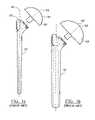
- FIGS. 1 a and 1 brepresent a prior art humeral system
- FIGS. 2 a and 2 brepresent two humeral prosthetics according to the teachings of the present invention with one shown in phantom;
- FIGS. 3 and 4represent exploded perspective views of the humeral prosthetic shown in FIG. 2 ;
- FIGS. 5 and 6represent views of the coupling portion of the prosthetic shown in FIGS. 3 and 4 ;
- FIG. 7is a cross sectional view of the prosthetic according to FIG. 3 shown implanted in a shoulder;
- FIG. 8is a cross sectional view of the prosthetic according to FIG. 4 shown implanted in a shoulder.
- FIGS. 9 and 10represent side views of an alternate embodiment of the present invention.
- FIGS. 2 a - 4represent a kit which contains a pair of modular humeral prosthesis 10 and 50 are shown.
- the first prosthesis 10which has a stem portion 12 , and humeral head 14 .
- the humeral head 14is joined to the stem 12 by means of a Morse Taper 18 .
- Components of the Morse Taper 18are formed on the stem 12 and the head 14 .
- a tapered shaft 19Disposed between a proximal end 16 and a distal end 17 of the stem 12 is a tapered shaft 19 having a first cross-sectional diameter.
- a coupling portion 21Disposed on the proximal end 16 of the stem portion 12 is a coupling portion 21 having a platform 24 .
- the platform 24has a lower surface 26 which mates with the resected bone surface 28 as shown in FIG. 2 .
- the platform 24further has an annular upper surface 30 which mates with the head 14 .
- Defined within the platform 24is the female portion 32 of Morse Taper 18 .
- the female portion 32has an axis 34 that is generally perpendicular to the upper surface 30 of the platform 24 .
- the axis 34is defined having a fixed distance 38 to the proximal end 16 of the stem portion 12 .
- the fixed distance 38is a function of one of the average cross sectional diameter or cross-sectional area of the tapered shaft 19 .
- the humeral head 14defines a hemispherical articulating surface 40 and a planar coupling surface 42 .
- the coupling surface 42functions to couple to the upper surface 30 of the platform 24 .
- Defined in the coupling surface 42is the male portion 43 of the Morse Taper 18 . It is envisioned that either the stem or the head can have either the male or female side of the Morse Taper. Furthermore, other fixation methods such as threaded members can be incorporated.
- the hole disposed in the stem 12is threaded to rotatably receive a threaded head portion.
- the hemispherical surface 40functions to rotatably mount to the glenoid (not shown).
- the head component 14can be comprised of any number of biocompatible materials, such as but not limited to titanium, cobalt chrome, stainless steel, ceramics or any other material that can serve as a bearing surface.
- the head component 14can articulate either on the natural glenoid or on a glenoid component (not shown) such as one made of cobalt chrome or any other suitable biocompatible material in order to provide for a metal-metal articulation.
- FIG. 2represents a second humeral prosthesis 50 according to the teachings of the present invention.
- the second stem portion 44is defined by a second tapered shaft 51 .
- the stemhas a platform 48 defining a head mating surface 50 .
- the axis 53 of the Morse Taper 52is defined at a second fixed distance 56 of the proximal end 58 of second prosthesis 50 .
- the axis 34 of the Morse Taper 52is substantially parallel to the axis 39 for the first prosthetic 10 .
- the fixed distance 56is a function of the average diameter or the cross sectional area of the stem.
- the second head portion 46which has a hemispherical surface 59 .
- the hemispherical surface 59has a radius smaller than the radius of the first humeral head 14 .
- the humeral prostheses 10 and 50 shown in FIG. 2are depicted sharing a common center line 60 which corresponds to the center line of the intramedullary canal to which the prostheses are being implanted.
- the center lines of the axis 34 and 53are displaced from each other a predetermined distance x and intersect the longitudinal axis 60 .
- the distance xis a function of the difference of the average tapered stem diameters or cross sectional area of stems 19 and 44 .
- each head 14 and 46have a lateral side 62 which are less than 2 millimeters and preferably less than 2 millimeters in the lateral side from the common center line or longitudinal axis 60 of the humeral prostheses 10 and 50 .
- Thisis opposed to the distance from the center line of the prior art systems (see FIG. 1 ) which overlap the center line more than 2 mm.
- the radius of curvaturewill change to provide a better angle of curvature with respect to the inferior side of the glenoid.
- FIGS. 3 and 4represent an exploded perspective view of the humeral prosthesis 10 and 50 shown in FIG. 2 .
- FIG. 3represents a prosthetic having a 6 millimeter diameter stem
- FIG. 4represents a prosthetic having a 15 millimeter diameter stem.
- the stem components 10 and 50can be configured in any number of shapes (e.g., curved, tapered, conical, cylindrical, radial, fluted, and so forth).
- the surface finish of the stem components 10 and 50can be smooth, plasma spray, porous coating, threaded, polished, grit blasted, and so forth).
- the material comprising the stem components 10 and 50can be any biocompatible material such as but not limited to titanium, cobalt chrome, stainless steel, ceramics, and so forth.
- the cross-sectional profile of the stem component 12may comprise many different shapes, and can either be used in a press-fit or cemented application for implantation.
- FIGS. 5 and 6best depict the humeral head coupling platforms 24 and 48 . Depicted is the relationship of the coupling member axes 25 and 53 with respect to the humeral prosthetic center lines 60 .
- the coupling mechanismis a first distance along the longitudinal axis from the first proximal end, while the second coupling mechanism is a second distance from the second proximal end. Shown in these views is the clear offset of the axes 25 and 53 from the proximal ends 22 of the stem portions. The difference in fixed distance can also be measured at any fixed point along the stems.
- FIGS. 7 and 8represent implanted humeral prostheses 10 and 50 . Shown are the prosthesis 10 and 50 disposed within the intermedullary canal 66 and 68 of the resected humerus 70 and 72 . In each case, the coupled head portions 14 and 46 are shown in articulating contact with a natural glenoid 74 . It is envisioned that the current system can be used with an artificial glenoid in a total joint replacement.
- FIGS. 9 and 10represent an alternate method for coupling the head portions 14 and 46 to the stem portions 10 and 50 .
- Shownis an intermediary member 82 which is coupled to the stem by way of a threaded post 84 further defined on the intermediary member 82 is the male side 84 of a Morse Taper 86 .
- the male side 84is coupled to the female portion 88 of the Morse Taper 86 defined in the head portions 14 and 46 .
- the humeral prosthesis 10is shown with stem 12 having longitudinal axis 25 , and proximal and distal ends 16 .
- the hemispherical head 14can be coupled to the proximal end having an apparent diameter of greater than about 51 mm where apparent diameter is the intersection of the head within the centerline.
- the hemispherical head 14overlaps the longitudinal axis 25 in the lateral direction less than about 5 mm and preferably less than 2 mm, when the distal end 17 of the stem 12 is extending in the inferior position.
- the humeral components 10 and 50can have a diameter greater than about 43 mm; wherein said hemispherical head overlaps the longitudinal axis 25 in the lateral direction less than 5 mm and preferably less than 2 mm when the distal end 17 of the stem 12 is extending in the inferior position.
Landscapes
- Health & Medical Sciences (AREA)
- Orthopedic Medicine & Surgery (AREA)
- Cardiology (AREA)
- Oral & Maxillofacial Surgery (AREA)
- Transplantation (AREA)
- Engineering & Computer Science (AREA)
- Biomedical Technology (AREA)
- Heart & Thoracic Surgery (AREA)
- Vascular Medicine (AREA)
- Life Sciences & Earth Sciences (AREA)
- Animal Behavior & Ethology (AREA)
- General Health & Medical Sciences (AREA)
- Public Health (AREA)
- Veterinary Medicine (AREA)
- Prostheses (AREA)
Abstract
Description
Claims (10)
Priority Applications (1)
| Application Number | Priority Date | Filing Date | Title |
|---|---|---|---|
| US10/358,079US7338528B2 (en) | 2003-02-04 | 2003-02-04 | Humeral stem with anatomical location of taper access for fixation of humeral head |
Applications Claiming Priority (1)
| Application Number | Priority Date | Filing Date | Title |
|---|---|---|---|
| US10/358,079US7338528B2 (en) | 2003-02-04 | 2003-02-04 | Humeral stem with anatomical location of taper access for fixation of humeral head |
Publications (2)
| Publication Number | Publication Date |
|---|---|
| US20040153161A1 US20040153161A1 (en) | 2004-08-05 |
| US7338528B2true US7338528B2 (en) | 2008-03-04 |
Family
ID=32771136
Family Applications (1)
| Application Number | Title | Priority Date | Filing Date |
|---|---|---|---|
| US10/358,079Expired - LifetimeUS7338528B2 (en) | 2003-02-04 | 2003-02-04 | Humeral stem with anatomical location of taper access for fixation of humeral head |
Country Status (1)
| Country | Link |
|---|---|
| US (1) | US7338528B2 (en) |
Cited By (34)
| Publication number | Priority date | Publication date | Assignee | Title |
|---|---|---|---|---|
| US20040230197A1 (en)* | 2003-03-10 | 2004-11-18 | Alain Tornier | Ancillary tool for positioning a glenoid implant |
| US20050049709A1 (en)* | 2003-08-25 | 2005-03-03 | Alain Tornier | Glenoid component of a shoulder prosthesis and complete shoulder prosthesis incorporating such a component |
| US20050165490A1 (en)* | 2003-12-19 | 2005-07-28 | Alain Tornier | Shoulder or hip prosthesis and process for fitting same |
| US20050278033A1 (en)* | 2004-06-15 | 2005-12-15 | Alain Tornier | Total shoulder prosthesis or inverted type |
| US20070225817A1 (en)* | 2006-03-21 | 2007-09-27 | Reubelt Leo M | Glenoid component with improved fixation stability |
| US20070225818A1 (en)* | 2006-03-21 | 2007-09-27 | Axiom Orthopaedics, Inc. | Non-spherical articulating surfaces in shoulder and hip replacement |
| US20070244564A1 (en)* | 2006-04-13 | 2007-10-18 | Tornier | Glenoid component with an anatomically optimized keel |
| US20080183297A1 (en)* | 2007-01-30 | 2008-07-31 | Tornier | Method and apparatus for fitting a shoulder prosthesis |
| US7462197B2 (en) | 2004-06-15 | 2008-12-09 | Tornier Sas | Glenoidal component of a shoulder prosthesis, set of elements constituting such a component and total shoulder prosthesis incorporating such a component |
| US7470287B2 (en) | 2004-06-28 | 2008-12-30 | Tornier Sas | Shoulder or hip prosthesis |
| US20090112328A1 (en)* | 2006-04-21 | 2009-04-30 | Alain Tornier | Shoulder or hip prosthesis and method for setting same |
| US20110098822A1 (en)* | 2007-01-30 | 2011-04-28 | Gilles Walch | Intra-articular joint replacement |
| US20110153024A1 (en)* | 2009-12-17 | 2011-06-23 | Zimmer, Inc. | Modular elbow prosthesis |
| US20120035733A1 (en)* | 2010-04-13 | 2012-02-09 | Biomet Manufacturing Corp. | Prosthetic having a modular soft tissue fixation mechanism |
| US20120116532A1 (en)* | 2009-07-10 | 2012-05-10 | Milux Holdings SA | Hip joint device and method |
| US8303665B2 (en) | 2004-06-15 | 2012-11-06 | Tornier Sas | Glenoidal component, set of such components and shoulder prosthesis incorporating such a glenoidal component |
| US20130325134A1 (en)* | 2012-05-31 | 2013-12-05 | Howmedica Osteonics Corp. | Lateral entry insert for cup trial |
| US20130325133A1 (en)* | 2012-05-31 | 2013-12-05 | Howmedica Osteonics Corp. | Lateral entry insert for cup trial |
| US8764845B2 (en)* | 2007-03-28 | 2014-07-01 | Depuy International Limited | Head component of an orthopaedic joint prosthesis |
| US8936647B2 (en) | 2012-06-22 | 2015-01-20 | Zimmer, Inc. | Elbow prosthesis |
| US9408652B2 (en) | 2010-04-27 | 2016-08-09 | Tornier Sas | Intra-articular joint replacement and method |
| US9421106B2 (en) | 2011-12-07 | 2016-08-23 | Howmedica Osteonics Corp. | Reverse shoulder baseplate with alignment guide for glenosphere |
| US9681960B2 (en) | 2014-05-16 | 2017-06-20 | Howmedica Osteonics Corp. | Guides for fracture system |
| USRE47149E1 (en) | 2011-12-09 | 2018-12-04 | Howmedica Osteonics Corp. | Surgical reaming instrument for shaping a bone cavity |
| US10149763B2 (en) | 2015-01-12 | 2018-12-11 | Howmedica Osteonics Corp. | Multipurpose void filling prosthesis |
| US10201374B2 (en) | 2012-06-22 | 2019-02-12 | Zimmer, Inc. | Assembly tool for a prosthesis |
| US10390972B2 (en) | 2016-01-15 | 2019-08-27 | Howmedica Osteonics Corp. | Humeral trial adaptor |
| US10575968B2 (en) | 2014-05-16 | 2020-03-03 | Howmedica Osteonics Corp. | Guides for fracture system |
| US10631993B2 (en) | 2010-10-22 | 2020-04-28 | Tornier, Inc. | Set of glenoid components for a shoulder prosthesis |
| US11033399B2 (en) | 2016-02-28 | 2021-06-15 | Integrated Shoulder Collaboration, Inc. | Shoulder arthroplasty implant system |
| US11172940B2 (en) | 2011-12-30 | 2021-11-16 | Howmedica Osteonics Corp. | Systems and methods for preparing bone voids to receive a prosthesis |
| US11457912B2 (en) | 2016-06-02 | 2022-10-04 | Parcus Medical, Llc | Suture tool and method of use |
| US11833055B2 (en) | 2016-02-28 | 2023-12-05 | Integrated Shoulder Collaboration, Inc. | Shoulder arthroplasty implant system |
| US12121243B2 (en) | 2013-03-13 | 2024-10-22 | Howmedica Osteonics Corp. | Void filling joint prosthesis and associated instruments |
Families Citing this family (21)
| Publication number | Priority date | Publication date | Assignee | Title |
|---|---|---|---|---|
| US7799086B2 (en) | 2002-04-25 | 2010-09-21 | Zimmer Technology, Inc. | Modular bone implant, tools, and method |
| WO2007031575A1 (en)* | 2005-09-16 | 2007-03-22 | Zimmer Gmbh | Insert and shell of a joint ball receptacle |
| EP1787603A1 (en)* | 2005-11-18 | 2007-05-23 | Zimmer GmbH | Basis-platform for an artificial joint |
| US8425614B2 (en)* | 2006-03-20 | 2013-04-23 | Biomet Manufacturing Corp. | Modular center pegged glenoid |
| WO2007109340A2 (en)* | 2006-03-21 | 2007-09-27 | Axiom Orthopaedics, Inc. | Femoral and humeral stem geometry and implantation method for orthopedic joint reconstruction |
| CA2702952C (en) | 2007-10-27 | 2017-01-03 | Parcus Medical, Llc | Suture anchor |
| GB2471290A (en)* | 2009-06-23 | 2010-12-29 | Keith Borowsky | Joint repair apparatus |
| FR2964859B1 (en) | 2010-09-17 | 2012-09-07 | Marc Duport | SPACING AND FASTENING RING FOR SHOULDER CUPS |
| FR2964858B1 (en) | 2010-09-17 | 2013-07-05 | Marc Duport | VIS-CAGE FOR ATTACHING A SHOULDER PROSTHESIS CUP |
| FR2964856B1 (en)* | 2010-09-17 | 2012-08-24 | Marc Duport | SHOULDER PROSTHESIS CUP WITH FIXATION RIBS |
| FR2964857B1 (en)* | 2010-09-17 | 2013-07-05 | Marc Duport | MODULAR CUP OF SHOULDER PROSTHESIS |
| EP2586387A1 (en) | 2011-10-31 | 2013-05-01 | Tornier Orthopedics Ireland Ltd. | Bone reamer |
| BR112015007174A8 (en) | 2012-10-29 | 2018-04-24 | Tornier Orthopedics Ireland Ltd | Modular reverse shoulder prosthesis and respective systems |
| WO2015171962A1 (en) | 2014-05-07 | 2015-11-12 | Bart Bracy | Multipart suture |
| FR3029769A1 (en) | 2014-12-10 | 2016-06-17 | Tornier Sa | KIT FOR A PROSTHESIS OF SHOULDER |
| EP3445292B1 (en) | 2016-04-19 | 2022-12-21 | Imascap SAS | Pre-operatively planned humeral implant and planning method |
| US11517301B2 (en) | 2016-06-02 | 2022-12-06 | Parcus Medical, Llc | Surgical tool and method of use |
| CA3087066A1 (en) | 2017-12-29 | 2019-07-04 | Tornier, Inc. | Patient specific humeral implant components |
| EP3520738B1 (en) | 2018-01-31 | 2021-01-06 | Tornier | Prosthesis for a fractured long bone |
| USD938590S1 (en)* | 2019-10-01 | 2021-12-14 | Howmedica Osteonics Corp. | Humeral implant |
| USD938034S1 (en) | 2020-03-31 | 2021-12-07 | Howmedica Osteonics Corp. | Humeral implant |
Citations (23)
| Publication number | Priority date | Publication date | Assignee | Title |
|---|---|---|---|---|
| US3842442A (en)* | 1972-09-04 | 1974-10-22 | Nat Res Dev | Endoprosthetic shoulder joint |
| US5314479A (en) | 1986-08-15 | 1994-05-24 | Depuy Inc. | Modular prosthesis |
| US5358526A (en) | 1991-12-27 | 1994-10-25 | Etablissements Tornier | Modular shoulder prosthesis |
| US5489309A (en)* | 1993-01-06 | 1996-02-06 | Smith & Nephew Richards Inc. | Modular humeral component system |
| US5549682A (en) | 1994-06-16 | 1996-08-27 | Roy; Stephen C. | Shoulder joint prosthesis with angular adjustment |
| US5702486A (en)* | 1994-02-22 | 1997-12-30 | Kirschner Medical Corporation | Modular humeral prosthesis for reconstruction of the humerus |
| US5910171A (en) | 1993-03-12 | 1999-06-08 | Hospital For Joint Diseases | Components for a modular shoulder and hip prosthesis |
| US6102953A (en)* | 1998-03-17 | 2000-08-15 | Acumed, Inc. | Shoulder prosthesis |
| US6120542A (en)* | 1995-06-08 | 2000-09-19 | Camino; Thomas S. | Large taper modular shoulder prosthesis |
| US6197063B1 (en) | 1997-04-11 | 2001-03-06 | Smith & Nephew, Inc. | Modular humeral prosthesis and method |
| US6197062B1 (en)* | 1999-01-11 | 2001-03-06 | Howmedica Osteonics, Corp. | Modular shoulder prosthesis system |
| US6206925B1 (en)* | 1997-09-12 | 2001-03-27 | Tornier Sa | Elbow prosthesis with indexed sphere |
| US6228120B1 (en)* | 1998-01-09 | 2001-05-08 | Alain Leonard | Surgical equipment for implanting a total shoulder prosthesis, and total shoulder prosthesis constituting same |
| US6283999B1 (en)* | 1999-01-29 | 2001-09-04 | Depuy Orthopaedics, Inc. | Shoulder prothesis with humeral fracture stem |
| US20010041940A1 (en) | 1999-12-31 | 2001-11-15 | Pearl Michael L. | Modular shoulder prostheses |
| US20010053935A1 (en) | 2000-05-03 | 2001-12-20 | Hartdegen Vernon D. | Multi modular trialing system and instrumentation |
| US6494913B1 (en)* | 1998-03-17 | 2002-12-17 | Acumed, Inc. | Shoulder prosthesis |
| US6508840B1 (en)* | 1999-04-07 | 2003-01-21 | Depuy Orthopaedis, Inc. | Collarless shoulder arthroplasty prosthesis |
| US20030028253A1 (en)* | 2001-07-11 | 2003-02-06 | Stone Kevin T. | Shoulder prosthesis |
| US6676705B1 (en)* | 2001-09-13 | 2004-01-13 | Eugene M. Wolf | Variable tilt angle taper lock shoulder prosthesis |
| US6736851B2 (en)* | 2002-06-28 | 2004-05-18 | Depuy Orthopaedics, Inc. | Modular shoulder prosthesis |
| US6776799B2 (en)* | 2002-09-30 | 2004-08-17 | Depuy Products, Inc. | Method and apparatus for replication of angular position of a humeral head of a shoulder prosthesis |
| US7011686B2 (en)* | 2002-09-30 | 2006-03-14 | Depuy Products, Inc. | Reverse-type humeral prosthesis |
Family Cites Families (3)
| Publication number | Priority date | Publication date | Assignee | Title |
|---|---|---|---|---|
| US53935A (en)* | 1866-04-10 | hodges | ||
| US41940A (en)* | 1864-03-15 | Improvement in elastic carriage-wheels | ||
| US49561A (en)* | 1865-08-22 | Improved liquid soap |
- 2003
- 2003-02-04USUS10/358,079patent/US7338528B2/ennot_activeExpired - Lifetime
Patent Citations (24)
| Publication number | Priority date | Publication date | Assignee | Title |
|---|---|---|---|---|
| US3842442A (en)* | 1972-09-04 | 1974-10-22 | Nat Res Dev | Endoprosthetic shoulder joint |
| US5314479A (en) | 1986-08-15 | 1994-05-24 | Depuy Inc. | Modular prosthesis |
| US5358526A (en) | 1991-12-27 | 1994-10-25 | Etablissements Tornier | Modular shoulder prosthesis |
| US5489309A (en)* | 1993-01-06 | 1996-02-06 | Smith & Nephew Richards Inc. | Modular humeral component system |
| US5910171A (en) | 1993-03-12 | 1999-06-08 | Hospital For Joint Diseases | Components for a modular shoulder and hip prosthesis |
| US5702486A (en)* | 1994-02-22 | 1997-12-30 | Kirschner Medical Corporation | Modular humeral prosthesis for reconstruction of the humerus |
| US5549682A (en) | 1994-06-16 | 1996-08-27 | Roy; Stephen C. | Shoulder joint prosthesis with angular adjustment |
| US6120542A (en)* | 1995-06-08 | 2000-09-19 | Camino; Thomas S. | Large taper modular shoulder prosthesis |
| US20010049561A1 (en) | 1997-04-11 | 2001-12-06 | Dews Paul M. | Modular humeral prosthesis and method |
| US6197063B1 (en) | 1997-04-11 | 2001-03-06 | Smith & Nephew, Inc. | Modular humeral prosthesis and method |
| US6206925B1 (en)* | 1997-09-12 | 2001-03-27 | Tornier Sa | Elbow prosthesis with indexed sphere |
| US6228120B1 (en)* | 1998-01-09 | 2001-05-08 | Alain Leonard | Surgical equipment for implanting a total shoulder prosthesis, and total shoulder prosthesis constituting same |
| US6102953A (en)* | 1998-03-17 | 2000-08-15 | Acumed, Inc. | Shoulder prosthesis |
| US6494913B1 (en)* | 1998-03-17 | 2002-12-17 | Acumed, Inc. | Shoulder prosthesis |
| US6197062B1 (en)* | 1999-01-11 | 2001-03-06 | Howmedica Osteonics, Corp. | Modular shoulder prosthesis system |
| US6283999B1 (en)* | 1999-01-29 | 2001-09-04 | Depuy Orthopaedics, Inc. | Shoulder prothesis with humeral fracture stem |
| US6508840B1 (en)* | 1999-04-07 | 2003-01-21 | Depuy Orthopaedis, Inc. | Collarless shoulder arthroplasty prosthesis |
| US20010041940A1 (en) | 1999-12-31 | 2001-11-15 | Pearl Michael L. | Modular shoulder prostheses |
| US20010053935A1 (en) | 2000-05-03 | 2001-12-20 | Hartdegen Vernon D. | Multi modular trialing system and instrumentation |
| US20030028253A1 (en)* | 2001-07-11 | 2003-02-06 | Stone Kevin T. | Shoulder prosthesis |
| US6676705B1 (en)* | 2001-09-13 | 2004-01-13 | Eugene M. Wolf | Variable tilt angle taper lock shoulder prosthesis |
| US6736851B2 (en)* | 2002-06-28 | 2004-05-18 | Depuy Orthopaedics, Inc. | Modular shoulder prosthesis |
| US6776799B2 (en)* | 2002-09-30 | 2004-08-17 | Depuy Products, Inc. | Method and apparatus for replication of angular position of a humeral head of a shoulder prosthesis |
| US7011686B2 (en)* | 2002-09-30 | 2006-03-14 | Depuy Products, Inc. | Reverse-type humeral prosthesis |
Cited By (75)
| Publication number | Priority date | Publication date | Assignee | Title |
|---|---|---|---|---|
| US20070250174A1 (en)* | 2003-03-10 | 2007-10-25 | Tornier | Ancillary tool for positioning a glenoid implant |
| US7887544B2 (en) | 2003-03-10 | 2011-02-15 | Tornier Sas | Ancillary tool for positioning a glenoid implant |
| US20040230197A1 (en)* | 2003-03-10 | 2004-11-18 | Alain Tornier | Ancillary tool for positioning a glenoid implant |
| US8187282B2 (en) | 2003-03-10 | 2012-05-29 | Tornier Sas | Ancillary tool for positioning a glenoid implant |
| US20050049709A1 (en)* | 2003-08-25 | 2005-03-03 | Alain Tornier | Glenoid component of a shoulder prosthesis and complete shoulder prosthesis incorporating such a component |
| US20050165490A1 (en)* | 2003-12-19 | 2005-07-28 | Alain Tornier | Shoulder or hip prosthesis and process for fitting same |
| US7465319B2 (en) | 2003-12-19 | 2008-12-16 | Tornier Sas | Shoulder or hip prosthesis and process for fitting same |
| US20050278033A1 (en)* | 2004-06-15 | 2005-12-15 | Alain Tornier | Total shoulder prosthesis or inverted type |
| US11523907B2 (en) | 2004-06-15 | 2022-12-13 | Tornier Sas | Glenoidal component, set of such components and shoulder prosthesis incorporating such a glenoidal component |
| US7462197B2 (en) | 2004-06-15 | 2008-12-09 | Tornier Sas | Glenoidal component of a shoulder prosthesis, set of elements constituting such a component and total shoulder prosthesis incorporating such a component |
| US8303665B2 (en) | 2004-06-15 | 2012-11-06 | Tornier Sas | Glenoidal component, set of such components and shoulder prosthesis incorporating such a glenoidal component |
| US10610363B2 (en) | 2004-06-15 | 2020-04-07 | Tornier Sas | Glenoidal component, set of such components and shoulder prosthesis incorporating such a glenoidal component |
| US7678150B2 (en) | 2004-06-15 | 2010-03-16 | Tornier Sas | Total shoulder prosthesis of an inverted type |
| US9545312B2 (en) | 2004-06-15 | 2017-01-17 | Tornier Sas | Glenoidal component, set of such components and shoulder prosthesis incorporating such a glenoidal component |
| US7470287B2 (en) | 2004-06-28 | 2008-12-30 | Tornier Sas | Shoulder or hip prosthesis |
| US20070225818A1 (en)* | 2006-03-21 | 2007-09-27 | Axiom Orthopaedics, Inc. | Non-spherical articulating surfaces in shoulder and hip replacement |
| US9474619B2 (en) | 2006-03-21 | 2016-10-25 | Tornier, Inc. | Glenoid component with improved fixation stability |
| US9433507B2 (en) | 2006-03-21 | 2016-09-06 | Tornier, Inc. | Non-spherical articulating surfaces in shoulder and hip replacement |
| US20070225817A1 (en)* | 2006-03-21 | 2007-09-27 | Reubelt Leo M | Glenoid component with improved fixation stability |
| US8080063B2 (en) | 2006-04-13 | 2011-12-20 | Tornier Sas | Glenoid component with an anatomically optimized keel |
| US20070244564A1 (en)* | 2006-04-13 | 2007-10-18 | Tornier | Glenoid component with an anatomically optimized keel |
| US20090112328A1 (en)* | 2006-04-21 | 2009-04-30 | Alain Tornier | Shoulder or hip prosthesis and method for setting same |
| US8277511B2 (en) | 2006-04-21 | 2012-10-02 | Tornier Sas | Shoulder or hip prosthesis and method for setting same |
| US11547572B2 (en) | 2007-01-30 | 2023-01-10 | Tornier Sas | Intra-articular joint replacement |
| US8974536B2 (en) | 2007-01-30 | 2015-03-10 | Tornier Sas | Intra-articular joint replacement |
| US20080183297A1 (en)* | 2007-01-30 | 2008-07-31 | Tornier | Method and apparatus for fitting a shoulder prosthesis |
| US9089435B2 (en) | 2007-01-30 | 2015-07-28 | Tornier Sas | Intra-articular joint replacement |
| US10413416B2 (en) | 2007-01-30 | 2019-09-17 | Tornier Sas | Method and apparatus for fitting a shoulder prosthesis |
| US10251755B2 (en) | 2007-01-30 | 2019-04-09 | Tornier Sas | Method and apparatus for fitting a shoulder prosthesis |
| US8864834B2 (en) | 2007-01-30 | 2014-10-21 | Tornier Sas | Method and apparatus for fitting a shoulder prosthesis |
| US11185417B2 (en) | 2007-01-30 | 2021-11-30 | Tornier Sas | Method and apparatus for fitting a shoulder prosthesis |
| US20110098822A1 (en)* | 2007-01-30 | 2011-04-28 | Gilles Walch | Intra-articular joint replacement |
| US8764845B2 (en)* | 2007-03-28 | 2014-07-01 | Depuy International Limited | Head component of an orthopaedic joint prosthesis |
| US9180014B2 (en)* | 2009-07-10 | 2015-11-10 | Peter Forsell | Hip joint device and method |
| US20120116532A1 (en)* | 2009-07-10 | 2012-05-10 | Milux Holdings SA | Hip joint device and method |
| US8968411B2 (en) | 2009-12-17 | 2015-03-03 | Zimmer, Inc. | Modular elbow prosthesis |
| US20110153024A1 (en)* | 2009-12-17 | 2011-06-23 | Zimmer, Inc. | Modular elbow prosthesis |
| US9345580B2 (en)* | 2010-04-13 | 2016-05-24 | Biomet Manufacturing, Llc | Prosthetic having a modular soft tissue fixation mechanism |
| US8715356B2 (en)* | 2010-04-13 | 2014-05-06 | Biomet Manufacturing, Llc | Prosthetic having a modular soft tissue fixation mechanism |
| US20140296986A1 (en)* | 2010-04-13 | 2014-10-02 | Biomet Manufacturing Llc | Prosthetic Having A Modular Soft Tissue Fixation Mechanism |
| US20120035733A1 (en)* | 2010-04-13 | 2012-02-09 | Biomet Manufacturing Corp. | Prosthetic having a modular soft tissue fixation mechanism |
| US9833326B2 (en) | 2010-04-13 | 2017-12-05 | Biomet Manufacturing, Llc | Prosthetic having a modular soft tissue fixation mechanism |
| US11771568B2 (en) | 2010-04-27 | 2023-10-03 | Tornier Sas | Intra-articular joint replacement and method |
| US10695195B2 (en) | 2010-04-27 | 2020-06-30 | Tornier Sas | Intra-articular joint replacement and method |
| US9408652B2 (en) | 2010-04-27 | 2016-08-09 | Tornier Sas | Intra-articular joint replacement and method |
| US12383415B2 (en) | 2010-04-27 | 2025-08-12 | Tornier Sas | Intra-articular joint replacement and method |
| US10631993B2 (en) | 2010-10-22 | 2020-04-28 | Tornier, Inc. | Set of glenoid components for a shoulder prosthesis |
| US11304815B2 (en) | 2010-10-22 | 2022-04-19 | Howmedica Osteonics Corp. | Set of glenoid components for a shoulder prosthesis |
| US9421106B2 (en) | 2011-12-07 | 2016-08-23 | Howmedica Osteonics Corp. | Reverse shoulder baseplate with alignment guide for glenosphere |
| USRE47149E1 (en) | 2011-12-09 | 2018-12-04 | Howmedica Osteonics Corp. | Surgical reaming instrument for shaping a bone cavity |
| USRE48163E1 (en) | 2011-12-09 | 2020-08-18 | Howmedica Osteonics Corp. | Surgical reaming instrument for shaping a bone cavity |
| US12262899B2 (en) | 2011-12-30 | 2025-04-01 | Howmedica Osteonics Corp. | Systems and methods for preparing bone voids to receive a prosthesis |
| US11172940B2 (en) | 2011-12-30 | 2021-11-16 | Howmedica Osteonics Corp. | Systems and methods for preparing bone voids to receive a prosthesis |
| US11877757B2 (en) | 2011-12-30 | 2024-01-23 | Howmedica Osteonics Corp. | Systems and methods for preparing bone voids to receive a prosthesis |
| US8858641B2 (en)* | 2012-05-31 | 2014-10-14 | Howmedica Osteonics Corp. | Lateral entry insert for cup trial |
| US20130325134A1 (en)* | 2012-05-31 | 2013-12-05 | Howmedica Osteonics Corp. | Lateral entry insert for cup trial |
| US8906102B2 (en)* | 2012-05-31 | 2014-12-09 | Howmedica Osteonics Corp. | Lateral entry insert for cup trial |
| US20130325133A1 (en)* | 2012-05-31 | 2013-12-05 | Howmedica Osteonics Corp. | Lateral entry insert for cup trial |
| US10195040B2 (en) | 2012-06-22 | 2019-02-05 | Zimmer, Inc. | Elbow prosthesis |
| US9474616B2 (en) | 2012-06-22 | 2016-10-25 | Zimmer, Inc. | Elbow prosthesis |
| US8936647B2 (en) | 2012-06-22 | 2015-01-20 | Zimmer, Inc. | Elbow prosthesis |
| US10201374B2 (en) | 2012-06-22 | 2019-02-12 | Zimmer, Inc. | Assembly tool for a prosthesis |
| US12274455B2 (en) | 2013-03-13 | 2025-04-15 | Howmedica Osteonics Corp. | Void filling joint prosthesis and associated instruments |
| US12121243B2 (en) | 2013-03-13 | 2024-10-22 | Howmedica Osteonics Corp. | Void filling joint prosthesis and associated instruments |
| US10575968B2 (en) | 2014-05-16 | 2020-03-03 | Howmedica Osteonics Corp. | Guides for fracture system |
| US9681960B2 (en) | 2014-05-16 | 2017-06-20 | Howmedica Osteonics Corp. | Guides for fracture system |
| US10149763B2 (en) | 2015-01-12 | 2018-12-11 | Howmedica Osteonics Corp. | Multipurpose void filling prosthesis |
| US12121441B2 (en) | 2015-01-12 | 2024-10-22 | Howmedica Osteonics Corp. | Bone void forming apparatus |
| US10390972B2 (en) | 2016-01-15 | 2019-08-27 | Howmedica Osteonics Corp. | Humeral trial adaptor |
| US11833055B2 (en) | 2016-02-28 | 2023-12-05 | Integrated Shoulder Collaboration, Inc. | Shoulder arthroplasty implant system |
| US12220319B2 (en) | 2016-02-28 | 2025-02-11 | Integrated Shoulder Collaboration, Inc. | Shoulder arthroplasty implant system |
| US11033399B2 (en) | 2016-02-28 | 2021-06-15 | Integrated Shoulder Collaboration, Inc. | Shoulder arthroplasty implant system |
| US12150861B2 (en) | 2016-02-28 | 2024-11-26 | Integrated Shoulder Collaboration, Inc. | Shoulder arthroplasty implant system |
| US12274436B2 (en) | 2016-06-02 | 2025-04-15 | Parcus Medical, Llc | Suture tool and method of use |
| US11457912B2 (en) | 2016-06-02 | 2022-10-04 | Parcus Medical, Llc | Suture tool and method of use |
Also Published As
| Publication number | Publication date |
|---|---|
| US20040153161A1 (en) | 2004-08-05 |
Similar Documents
| Publication | Publication Date | Title |
|---|---|---|
| US7338528B2 (en) | Humeral stem with anatomical location of taper access for fixation of humeral head | |
| US9283083B2 (en) | Shoulder implant assembly | |
| US11096792B2 (en) | Shoulder prosthesis with variable inclination humeral head component | |
| EP3078339B1 (en) | Device for retroversion correction for shoulder arthroplasty | |
| US6126694A (en) | Universal distal broach and stem trial | |
| US7179296B2 (en) | Partially constrained ball and socket | |
| EP1402854B1 (en) | Reverse-type humeral prosthesis | |
| US8062376B2 (en) | Shoulder implant assembly | |
| US8845743B2 (en) | Interlocking reverse shoulder prosthesis method | |
| US6699290B1 (en) | Modular elbow | |
| US7753959B2 (en) | Modular center pegged glenoid | |
| US8425614B2 (en) | Modular center pegged glenoid | |
| US20110106267A1 (en) | Shoulder prosthesis adjustable humeral head mechanism | |
| US20030208277A1 (en) | Modular elbow | |
| US20040193276A1 (en) | Modular articulating surface replacement prosthesis | |
| US12186196B2 (en) | Elbow arthroplasty apparatus, system, and method | |
| US20060106463A1 (en) | Prosthesis | |
| US12064356B2 (en) | Multi-size acetabular impactor | |
| US20220249241A1 (en) | Reverse shoulder prosthesis and related methods |
Legal Events
| Date | Code | Title | Description |
|---|---|---|---|
| AS | Assignment | Owner name:BIOMET MANUFACTURING CORP., INDIANA Free format text:ASSIGNMENT OF ASSIGNORS INTEREST;ASSIGNORS:STONE, KEVIN T.;CORDARO, NICHOLAS M.;REEL/FRAME:014060/0888;SIGNING DATES FROM 20030421 TO 20030430 | |
| AS | Assignment | Owner name:BANK OF AMERICA, N.A., AS ADMINISTRATIVE AGENT FOR Free format text:SECURITY AGREEMENT;ASSIGNORS:LVB ACQUISITION, INC.;BIOMET, INC.;REEL/FRAME:020362/0001 Effective date:20070925 | |
| STCF | Information on status: patent grant | Free format text:PATENTED CASE | |
| FPAY | Fee payment | Year of fee payment:4 | |
| AS | Assignment | Owner name:BIOMET MANUFACTURING, LLC, INDIANA Free format text:CHANGE OF NAME;ASSIGNOR:BIOMET MANUFACTURING CORPORATION;REEL/FRAME:030656/0702 Effective date:20130603 | |
| FPAY | Fee payment | Year of fee payment:8 | |
| AS | Assignment | Owner name:LVB ACQUISITION, INC., INDIANA Free format text:RELEASE OF SECURITY INTEREST IN PATENTS RECORDED AT REEL 020362/ FRAME 0001;ASSIGNOR:BANK OF AMERICA, N.A., AS ADMINISTRATIVE AGENT;REEL/FRAME:037155/0133 Effective date:20150624 Owner name:BIOMET, INC., INDIANA Free format text:RELEASE OF SECURITY INTEREST IN PATENTS RECORDED AT REEL 020362/ FRAME 0001;ASSIGNOR:BANK OF AMERICA, N.A., AS ADMINISTRATIVE AGENT;REEL/FRAME:037155/0133 Effective date:20150624 | |
| MAFP | Maintenance fee payment | Free format text:PAYMENT OF MAINTENANCE FEE, 12TH YEAR, LARGE ENTITY (ORIGINAL EVENT CODE: M1553); ENTITY STATUS OF PATENT OWNER: LARGE ENTITY Year of fee payment:12 |