US7338509B2 - Electroactive polymer actuated sheath for implantable or insertable medical device - Google Patents
Electroactive polymer actuated sheath for implantable or insertable medical deviceDownload PDFInfo
- Publication number
- US7338509B2 US7338509B2US10/702,314US70231403AUS7338509B2US 7338509 B2US7338509 B2US 7338509B2US 70231403 AUS70231403 AUS 70231403AUS 7338509 B2US7338509 B2US 7338509B2
- Authority
- US
- United States
- Prior art keywords
- medical device
- sheath
- delivery system
- active member
- device delivery
- Prior art date
- Legal status (The legal status is an assumption and is not a legal conclusion. Google has not performed a legal analysis and makes no representation as to the accuracy of the status listed.)
- Active, expires
Links
- 229920001746electroactive polymerPolymers0.000titleclaimsabstractdescription39
- 229920000128polypyrrolePolymers0.000claimsabstractdescription21
- 238000000034methodMethods0.000claimsabstractdescription12
- 230000007246mechanismEffects0.000claimsdescription7
- 238000003780insertionMethods0.000claimsdescription4
- 230000037431insertionEffects0.000claimsdescription4
- -1for examplePolymers0.000abstractdescription8
- 229920000642polymerPolymers0.000description33
- 239000003792electrolyteSubstances0.000description22
- 150000002500ionsChemical class0.000description12
- 229910001415sodium ionInorganic materials0.000description11
- FKNQFGJONOIPTF-UHFFFAOYSA-NSodium cationChemical compound[Na+]FKNQFGJONOIPTF-UHFFFAOYSA-N0.000description7
- 150000001768cationsChemical class0.000description7
- 230000008602contractionEffects0.000description7
- 239000000463materialSubstances0.000description6
- 230000009467reductionEffects0.000description6
- 238000013461designMethods0.000description5
- 239000000499gelSubstances0.000description5
- 238000007254oxidation reactionMethods0.000description5
- 239000000243solutionSubstances0.000description5
- 239000000835fiberSubstances0.000description4
- 239000012530fluidSubstances0.000description4
- 230000003647oxidationEffects0.000description4
- 239000007787solidSubstances0.000description4
- FAPWRFPIFSIZLT-UHFFFAOYSA-MSodium chlorideChemical compound[Na+].[Cl-]FAPWRFPIFSIZLT-UHFFFAOYSA-M0.000description3
- 150000001450anionsChemical class0.000description3
- 230000008901benefitEffects0.000description3
- 230000008859changeEffects0.000description3
- 239000004020conductorSubstances0.000description3
- YRIUSKIDOIARQF-UHFFFAOYSA-Ndodecyl benzenesulfonateChemical compoundCCCCCCCCCCCCOS(=O)(=O)C1=CC=CC=C1YRIUSKIDOIARQF-UHFFFAOYSA-N0.000description3
- 229940071161dodecylbenzenesulfonateDrugs0.000description3
- 230000000694effectsEffects0.000description3
- 239000007788liquidSubstances0.000description3
- 229910052751metalInorganic materials0.000description3
- 239000002184metalSubstances0.000description3
- HLXZNVUGXRDIFK-UHFFFAOYSA-Nnickel titaniumChemical compound[Ti].[Ti].[Ti].[Ti].[Ti].[Ti].[Ti].[Ti].[Ti].[Ti].[Ti].[Ni].[Ni].[Ni].[Ni].[Ni].[Ni].[Ni].[Ni].[Ni].[Ni].[Ni].[Ni].[Ni].[Ni]HLXZNVUGXRDIFK-UHFFFAOYSA-N0.000description3
- 229910001000nickel titaniumInorganic materials0.000description3
- 230000004044responseEffects0.000description3
- 230000002792vascularEffects0.000description3
- 210000001367arteryAnatomy0.000description2
- 238000000576coating methodMethods0.000description2
- 229920000547conjugated polymerPolymers0.000description2
- 210000004351coronary vesselAnatomy0.000description2
- 238000012631diagnostic techniqueMethods0.000description2
- 239000002019doping agentSubstances0.000description2
- 238000002594fluoroscopyMethods0.000description2
- 230000006870functionEffects0.000description2
- PCHJSUWPFVWCPO-UHFFFAOYSA-NgoldChemical compound[Au]PCHJSUWPFVWCPO-UHFFFAOYSA-N0.000description2
- 229910052737goldInorganic materials0.000description2
- 239000010931goldSubstances0.000description2
- 239000003550markerSubstances0.000description2
- 230000002093peripheral effectEffects0.000description2
- BASFCYQUMIYNBI-UHFFFAOYSA-NplatinumChemical compound[Pt]BASFCYQUMIYNBI-UHFFFAOYSA-N0.000description2
- 229920003229poly(methyl methacrylate)Polymers0.000description2
- 239000005518polymer electrolyteSubstances0.000description2
- 239000004926polymethyl methacrylateSubstances0.000description2
- 150000003839saltsChemical class0.000description2
- 239000011780sodium chlorideSubstances0.000description2
- 238000012546transferMethods0.000description2
- 229920001817AgarPolymers0.000description1
- 229910019142PO4Inorganic materials0.000description1
- 244000208734Pisonia aculeataSpecies0.000description1
- 229920001609Poly(3,4-ethylenedioxythiophene)Polymers0.000description1
- XUIMIQQOPSSXEZ-UHFFFAOYSA-NSiliconChemical compound[Si]XUIMIQQOPSSXEZ-UHFFFAOYSA-N0.000description1
- PIDSPMKZWFCAMN-UHFFFAOYSA-N[H]N1C(C)=CC=C1=C1=CC=C(=C2=CC=C(=C3=CC=C(=C4=CC=C(=C5=CC=C(=C6=CC=C(=C7=CC=C(=C)N7[H])N6[H])N5[H])N4[H])N3[H])N2[H])N1[H]Chemical compound[H]N1C(C)=CC=C1=C1=CC=C(=C2=CC=C(=C3=CC=C(=C4=CC=C(=C5=CC=C(=C6=CC=C(=C7=CC=C(=C)N7[H])N6[H])N5[H])N4[H])N3[H])N2[H])N1[H]PIDSPMKZWFCAMN-UHFFFAOYSA-N0.000description1
- 230000004913activationEffects0.000description1
- 230000002730additional effectEffects0.000description1
- HSFWRNGVRCDJHI-UHFFFAOYSA-Nalpha-acetyleneNatural productsC#CHSFWRNGVRCDJHI-UHFFFAOYSA-N0.000description1
- 238000004873anchoringMethods0.000description1
- 210000000709aortaAnatomy0.000description1
- 239000007864aqueous solutionSubstances0.000description1
- 230000036760body temperatureEffects0.000description1
- 239000008366buffered solutionSubstances0.000description1
- 210000000748cardiovascular systemAnatomy0.000description1
- 238000005266castingMethods0.000description1
- 239000011248coating agentSubstances0.000description1
- 239000002322conducting polymerSubstances0.000description1
- 229920001940conductive polymerPolymers0.000description1
- 238000010276constructionMethods0.000description1
- 238000007887coronary angioplastyMethods0.000description1
- 230000007797corrosionEffects0.000description1
- 238000005260corrosionMethods0.000description1
- 230000007423decreaseEffects0.000description1
- 238000000151depositionMethods0.000description1
- 238000003618dip coatingMethods0.000description1
- 238000002224dissectionMethods0.000description1
- GVGUFUZHNYFZLC-UHFFFAOYSA-Ndodecyl benzenesulfonate;sodiumChemical compound[Na].CCCCCCCCCCCCOS(=O)(=O)C1=CC=CC=C1GVGUFUZHNYFZLC-UHFFFAOYSA-N0.000description1
- 238000004070electrodepositionMethods0.000description1
- 230000003073embolic effectEffects0.000description1
- 238000001125extrusionMethods0.000description1
- 239000011888foilSubstances0.000description1
- 239000011245gel electrolyteSubstances0.000description1
- 208000025339heart septal defectDiseases0.000description1
- 239000007943implantSubstances0.000description1
- 238000002513implantationMethods0.000description1
- 230000006872improvementEffects0.000description1
- 238000001727in vivoMethods0.000description1
- 230000001939inductive effectEffects0.000description1
- 238000005259measurementMethods0.000description1
- 238000012986modificationMethods0.000description1
- 230000004048modificationEffects0.000description1
- NBIIXXVUZAFLBC-UHFFFAOYSA-KphosphateChemical compound[O-]P([O-])([O-])=ONBIIXXVUZAFLBC-UHFFFAOYSA-K0.000description1
- 239000010452phosphateSubstances0.000description1
- 238000000206photolithographyMethods0.000description1
- 230000004962physiological conditionEffects0.000description1
- 229910052697platinumInorganic materials0.000description1
- 229920000553poly(phenylenevinylene)Polymers0.000description1
- 229920002492poly(sulfone)Polymers0.000description1
- 229920001197polyacetylenePolymers0.000description1
- 229920000767polyanilinePolymers0.000description1
- 238000006116polymerization reactionMethods0.000description1
- 229920000123polythiophenePolymers0.000description1
- 230000008569processEffects0.000description1
- 230000008439repair processEffects0.000description1
- 208000037803restenosisDiseases0.000description1
- 238000012552reviewMethods0.000description1
- 239000004065semiconductorSubstances0.000description1
- 239000012781shape memory materialSubstances0.000description1
- 229910052710siliconInorganic materials0.000description1
- 239000010703siliconSubstances0.000description1
- 229940080264sodium dodecylbenzenesulfonateDrugs0.000description1
- 241000894007speciesSpecies0.000description1
- 238000004528spin coatingMethods0.000description1
- 229910001220stainless steelInorganic materials0.000description1
- 239000010935stainless steelSubstances0.000description1
- 230000000638stimulationEffects0.000description1
- BDHFUVZGWQCTTF-UHFFFAOYSA-MsulfonateChemical compound[O-]S(=O)=OBDHFUVZGWQCTTF-UHFFFAOYSA-M0.000description1
- 230000007704transitionEffects0.000description1
- 238000002604ultrasonographyMethods0.000description1
Images


Classifications
- A—HUMAN NECESSITIES
- A61—MEDICAL OR VETERINARY SCIENCE; HYGIENE
- A61F—FILTERS IMPLANTABLE INTO BLOOD VESSELS; PROSTHESES; DEVICES PROVIDING PATENCY TO, OR PREVENTING COLLAPSING OF, TUBULAR STRUCTURES OF THE BODY, e.g. STENTS; ORTHOPAEDIC, NURSING OR CONTRACEPTIVE DEVICES; FOMENTATION; TREATMENT OR PROTECTION OF EYES OR EARS; BANDAGES, DRESSINGS OR ABSORBENT PADS; FIRST-AID KITS
- A61F2/00—Filters implantable into blood vessels; Prostheses, i.e. artificial substitutes or replacements for parts of the body; Appliances for connecting them with the body; Devices providing patency to, or preventing collapsing of, tubular structures of the body, e.g. stents
- A61F2/95—Instruments specially adapted for placement or removal of stents or stent-grafts
- A61F2/962—Instruments specially adapted for placement or removal of stents or stent-grafts having an outer sleeve
- A—HUMAN NECESSITIES
- A61—MEDICAL OR VETERINARY SCIENCE; HYGIENE
- A61F—FILTERS IMPLANTABLE INTO BLOOD VESSELS; PROSTHESES; DEVICES PROVIDING PATENCY TO, OR PREVENTING COLLAPSING OF, TUBULAR STRUCTURES OF THE BODY, e.g. STENTS; ORTHOPAEDIC, NURSING OR CONTRACEPTIVE DEVICES; FOMENTATION; TREATMENT OR PROTECTION OF EYES OR EARS; BANDAGES, DRESSINGS OR ABSORBENT PADS; FIRST-AID KITS
- A61F2/00—Filters implantable into blood vessels; Prostheses, i.e. artificial substitutes or replacements for parts of the body; Appliances for connecting them with the body; Devices providing patency to, or preventing collapsing of, tubular structures of the body, e.g. stents
- A61F2/95—Instruments specially adapted for placement or removal of stents or stent-grafts
- A61F2/962—Instruments specially adapted for placement or removal of stents or stent-grafts having an outer sleeve
- A61F2/966—Instruments specially adapted for placement or removal of stents or stent-grafts having an outer sleeve with relative longitudinal movement between outer sleeve and prosthesis, e.g. using a push rod
- A—HUMAN NECESSITIES
- A61—MEDICAL OR VETERINARY SCIENCE; HYGIENE
- A61L—METHODS OR APPARATUS FOR STERILISING MATERIALS OR OBJECTS IN GENERAL; DISINFECTION, STERILISATION OR DEODORISATION OF AIR; CHEMICAL ASPECTS OF BANDAGES, DRESSINGS, ABSORBENT PADS OR SURGICAL ARTICLES; MATERIALS FOR BANDAGES, DRESSINGS, ABSORBENT PADS OR SURGICAL ARTICLES
- A61L31/00—Materials for other surgical articles, e.g. stents, stent-grafts, shunts, surgical drapes, guide wires, materials for adhesion prevention, occluding devices, surgical gloves, tissue fixation devices
- A61L31/14—Materials characterised by their function or physical properties, e.g. injectable or lubricating compositions, shape-memory materials, surface modified materials
- A—HUMAN NECESSITIES
- A61—MEDICAL OR VETERINARY SCIENCE; HYGIENE
- A61B—DIAGNOSIS; SURGERY; IDENTIFICATION
- A61B17/00—Surgical instruments, devices or methods
- A61B2017/00831—Material properties
- A61B2017/00867—Material properties shape memory effect
- A61B2017/00871—Material properties shape memory effect polymeric
- A—HUMAN NECESSITIES
- A61—MEDICAL OR VETERINARY SCIENCE; HYGIENE
- A61F—FILTERS IMPLANTABLE INTO BLOOD VESSELS; PROSTHESES; DEVICES PROVIDING PATENCY TO, OR PREVENTING COLLAPSING OF, TUBULAR STRUCTURES OF THE BODY, e.g. STENTS; ORTHOPAEDIC, NURSING OR CONTRACEPTIVE DEVICES; FOMENTATION; TREATMENT OR PROTECTION OF EYES OR EARS; BANDAGES, DRESSINGS OR ABSORBENT PADS; FIRST-AID KITS
- A61F2/00—Filters implantable into blood vessels; Prostheses, i.e. artificial substitutes or replacements for parts of the body; Appliances for connecting them with the body; Devices providing patency to, or preventing collapsing of, tubular structures of the body, e.g. stents
- A61F2/95—Instruments specially adapted for placement or removal of stents or stent-grafts
- A61F2/958—Inflatable balloons for placing stents or stent-grafts
- A61F2002/9583—Means for holding the stent on the balloon, e.g. using protrusions, adhesives or an outer sleeve
- A—HUMAN NECESSITIES
- A61—MEDICAL OR VETERINARY SCIENCE; HYGIENE
- A61M—DEVICES FOR INTRODUCING MEDIA INTO, OR ONTO, THE BODY; DEVICES FOR TRANSDUCING BODY MEDIA OR FOR TAKING MEDIA FROM THE BODY; DEVICES FOR PRODUCING OR ENDING SLEEP OR STUPOR
- A61M25/00—Catheters; Hollow probes
- A61M25/0021—Catheters; Hollow probes characterised by the form of the tubing
- A61M25/0023—Catheters; Hollow probes characterised by the form of the tubing by the form of the lumen, e.g. cross-section, variable diameter
- A61M2025/0024—Expandable catheters or sheaths
- A—HUMAN NECESSITIES
- A61—MEDICAL OR VETERINARY SCIENCE; HYGIENE
- A61M—DEVICES FOR INTRODUCING MEDIA INTO, OR ONTO, THE BODY; DEVICES FOR TRANSDUCING BODY MEDIA OR FOR TAKING MEDIA FROM THE BODY; DEVICES FOR PRODUCING OR ENDING SLEEP OR STUPOR
- A61M25/00—Catheters; Hollow probes
- A61M25/0043—Catheters; Hollow probes characterised by structural features
- A61M2025/0058—Catheters; Hollow probes characterised by structural features having an electroactive polymer material, e.g. for steering purposes, for control of flexibility, for locking, for opening or closing
- A—HUMAN NECESSITIES
- A61—MEDICAL OR VETERINARY SCIENCE; HYGIENE
- A61M—DEVICES FOR INTRODUCING MEDIA INTO, OR ONTO, THE BODY; DEVICES FOR TRANSDUCING BODY MEDIA OR FOR TAKING MEDIA FROM THE BODY; DEVICES FOR PRODUCING OR ENDING SLEEP OR STUPOR
- A61M25/00—Catheters; Hollow probes
- A61M25/01—Introducing, guiding, advancing, emplacing or holding catheters
- A61M25/06—Body-piercing guide needles or the like
- A61M25/0662—Guide tubes
Definitions
- This inventionrelates to sheaths for use in connection with the implantation or insertion of medical devices, such as stents.
- a guiding catheteris percutaneously introduced into the cardiovascular system of a patient and advanced through the aorta until the distal end of the catheter is in the ostium of the desired coronary artery.
- a guidewireis then advanced through the guiding catheter and across the site to be treated in the coronary artery.
- An over-the-wire balloon catheteris then advanced over the guide wire to the treatment site, and the balloon is expanded to reopen the artery.
- the over-the-wire cathetermay have a guide wire lumen which is as long as the catheter, or it may be a rapid exchange catheter in which the guide wire lumen is substantially shorter than the catheter.
- a fixed wire devicemay also be used. This device features a guide wire that is affixed to the catheter and cannot be removed.
- a physiciancan implant an intravascular prosthesis, for example, a stent, inside the artery at the treatment site.
- the stentmay be, for example, a self-expanding stent or a balloon expandable stent.
- the stentis typically delivered on a balloon and the balloon is used to expand the stent.
- the self-expanding stentsmay be made of shape memory materials such as nitinol or of other designs that exhibit self-expansion characteristics.
- a stente.g., a coronary vascular stent or another type of stent, such as a peripheral vascular stent, a renal stent, a biliary stent, etc.
- an optional balloonare positioned at the distal end of the catheter.
- the stent and optional balloonare held down and covered by a delivery sheath.
- the sheathis retracted in a proximal direction on the catheter to expose the stent. After the sheath is removed, the stent is free to self-expand or be expanded with a balloon.
- a medical devicedeployment system that utilizes a retractable sheath
- one problem that is frequently encounteredis the frictional forces that are generated between the sheath and the underlying medical device (e.g., a stent) upon retraction. These forces can damage the underlying stent.
- stent coatingsmay be formed from fragile materials and can be damaged upon retraction of the overlying sheath.
- a medical device delivery sheathwhich comprises an active member that volumetrically expands and contracts upon application of an appropriate electrical potential.
- the active memberfurther comprises an electroactive polymer, for example, polypyrrole.
- the delivery sheathcan be formed using one or more active members.
- a single active memberis provided in the form of an annulus.
- the annular active membercan further comprise conductive layer on its outside surface, for example, to function as an electrode for the active member and to direct the active member in a radially inward direction.
- a medical device delivery systemwhich comprises: (a) an elongate body adapted for insertion into a body lumen, the elongate body having distal and proximal ends; (b) the above delivery sheath, wherein the delivery sheath is disposed over all or a portion of the elongate body and is adapted to cover at least a portion of a medical device, for example, a stent; and (c) a control unit electrically coupled to the active member and adapted to apply electrical potentials that are effective to volumetrically expand and contract the active member, thereby actuating the sheath.
- the medical device delivery systemalso typically comprises a retraction mechanism for retracting the delivery sheath.
- the retraction mechanismcan comprise, for example, an electroactive polymer actuator, a mechanical pull wire, or other system for axially displacing the delivery sheath.
- a method for delivering a medical device to a lumen of a patientcomprises: (a) providing the above medical device delivery system, wherein the medical device is disposed proximate the distal end of the elongate body and wherein the delivery sheath at least partially covers the medical device; (b) inserting the distal end of the elongate body into the lumen; and (c) operating the control unit to actuate the delivery sheath, thereby at least partially disengaging the delivery sheath from the medical device.
- the methodfurther comprises: (a) retracting the delivery sheath from the medical device, for example, using a retraction mechanism like the above; and (b) disengaging the medical device from the elongate body.
- An advantage of the present inventionis that frictional forces are reduced between the delivery sheath and an underlying medical device upon retraction of the sheath. This allows for smoother retraction of the sheath with less axial force, and decreases the possibility that the underlying prosthesis will be damaged.
- Another advantage of the present inventionis that delivery sheaths are provided, which are lightweight, flexible, simple, and easily manufactured.
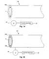
- FIG. 1Ais a schematic illustration of an electroactive-polymer-actuated delivery sheath in accordance with an embodiment of the present invention.
- FIG. 1Bis a schematic illustration of an EAP-actuated delivery sheath in accordance with another embodiment of the present invention.
- FIG. 2Ais an illustration of an over-the-wire delivery system comprising an electroactive-polymer-actuated delivery sheath in accordance with an embodiment of the present invention.
- FIG. 2Bis an enlarged view of the middle section of the over-the-wire delivery system of FIG. 2A .
- FIG. 3is an illustration of a rapid exchange delivery system comprising an electroactive-polymer-actuated delivery sheath in accordance with an embodiment of the present invention.
- FIG. 4is a schematic illustration of an electroactive-polymer-actuated delivery sheath in accordance with another embodiment of the present invention.
- FIG. 5is a schematic cross-sectional view of an electroactive polymer actuator.
- Electroactive polymersare polymers characterized by their ability to change shape in response to electrical stimulation.
- the electroactive polymers that are typically used in connection with the present inventionare ionic EAPs, more typically those EAPs that feature a conjugated backbone and have the ability to increase electrical conductivity under oxidation or reduction.
- EAPsare polypyrrole, polyaniline, polythiophenes, polyethylenedioxythiophene, poly(p-phenylene vinylene), polysulfone and polyacetylene.
- Polypyrrolewhich is one of the most stable of these polymers under physiological conditions, is pictured below:
- EAPsare typically semi-conductors in their pure form. However, upon oxidation or reduction of the polymer, the electrical conductivity is understood to be changed from a semi-conductive regime to a semi-metallic regime. Such oxidation and reduction is believed to lead to a charge imbalance that, in turn, results in a flow of ions into or out of the material. These ions typically enter/exit the polymer from/into an ionically conductive electrolyte medium associated with the electroactive polymer.
- Conductive EAPsalso have a number of additional properties that make them attractive for use in the devices of the present invention, including the following: (a) they are lightweight, flexible, and easily manufactured; (b) small changes in potential (e.g., potential changes on the order of 1V) can be used to effect volume change; (c) EAP regions can be created using a variety of techniques, for example, electrodeposition; and (d) EAP regions can be patterned, for example, using photolithography, if desired.
- Medical device delivery systems constructed in accordance with the present inventiongenerally include an elongated catheter body, a medical device (e.g., a stent) positioned near the distal end of the catheter body, and a delivery sheath overlying the medical device.
- the delivery sheathholds down and covers the medical device.
- the delivery sheathis an EAP-actuated delivery sheath that tightens and relaxes its hold on the underlying medical device depending upon the applied voltage.
- the medical device delivery systems of the present inventiongenerally comprise the following elements: (a) a source of electrical potential, (b) an active member comprising an electroactive polymer, (c) a counter electrode and (d) an electrolyte in contact with both the active member and the counter electrode.
- the electrolytewhich is in contact with at least a portion of the surface of the active member, allows for the flow of ions and thus acts as a source/sink for the ions.
- the electrolytemay be, for example, a liquid, a gel, or a solid, so long as ion movement is allowed.
- the electrolyteis a liquid, it may be, for example, an aqueous solution containing a salt, for example, a KCl solution, an NaCl solution, a phosphate buffered solution, a sodium dodecylbenzene sulfonate solution, physiological fluid, and so forth.
- the electrolyteis a gel
- itmay be, for example, a salt-containing agar gel or polymethylmethacrylate (PMMA) gel.
- PMMApolymethylmethacrylate
- the electrolyteis a solid, it may be, for example, a polymer electrolyte.
- the counter electrodemay be formed from any suitable electrical conductor, for example, a conducting polymer, a conducting gel, or a metal, for example, stainless steel, gold or platinum. At least a portion of the surface of the counter electrode is typically in contact with the electrolyte, in order to provide a return path for charge.
- the EAP-containing active membercontracts or expands in response to the flow of ions out of, or into, the same.
- any electroactive polymer that exhibits contractile or expansile propertiesmay be used in connection with the various aspects of the invention, including those set for above.
- the active memberis a polypyrrole-containing active member.
- Polypyrrole-containing active memberscan be fabricated using a number of known techniques, for example, extrusion, casting, dip coating, spin coating, or electro-polymerization/deposition techniques. Polypyrrole-containing active regions can be patterned using lithographic techniques, if desired.
- the active membercomprises polypyrrole (PPy) doped with dodecylbenzene sulfonate (DBS) anions.
- DBSdodecylbenzene sulfonate
- the cationsWhen placed in contact with an electrolyte containing small mobile cations, for example, Na + cations, and when a current is passed between the polypyrrole-containing active member and the counter electrode, the cations are inserted/removed upon reduction/oxidation of the polymer, leading to expansion/contraction of the same.
- This processcan be represented by the following equation: PPy + (DBS ⁇ )+Na + +e ⁇ PPy°(Na + DBS ⁇ ) where Na + represents a sodium ion, e ⁇ represents an electron, PPy + represents the oxidized state of the polymer, PPy° represents the reduced state of the polymer, and species are enclosed in parentheses to indicate that they are incorporated into the polymer.
- the sodium ionsare supplied by the electrolyte (which can be, for example, an aqueous electrolyte, a gel electrolyte or a solid polymer electrolyte) that is in contact with the electroactive polymer member.
- the positive charges on the backboneare at least partially compensated by the DBS ⁇ anions present within the polymer.
- the immobile DBS ⁇ ionscannot exit the polymer to maintain charge neutrality, so the smaller, more mobile, Na + ions enter the polymer, expanding the volume of the same.
- the Na + ionsagain exit the polymer into the electrolyte, reducing the volume of the polymer.
- the source of electrical potential for use in connection with the present inventioncan be quite simple, consisting, for example, of a dc battery and an on/off switch.
- more complex systemscan be utilized. For example, an electrical link and be established with a microprocessor, allowing a complex set of control signals to be sent to the EAP-containing active member(s) within the sheath.
- These more complex systemsmay be used, for example, where multiple active members are used to exert complex dimensional changes.
- EAP-containing active regionscan be provided that either expand or contract when an applied voltage of appropriate value is interrupted. Therefore, in some embodiments of the invention, the sheath formed from the EAP will tighten its grip on the underlying medical device when an applied electrical potential is interrupted, while in other embodiments, the sheath will loosen its hold.
- EAP actuatorstheir design considerations, and the materials and components that may be employed therein, can be found, for example, in E. W. H. Jager, E. Smela, O. Inganäs, “Microfabricating Conjugated Polymer Actuators,” Science, 290, 1540-1545, 2000; E. Smela, M. Kallenbach, and J. Holdenried, “Electrochemically Driven Polypyrrole Bilayers for Moving and Positioning Bulk Micromachined Silicon Plates,” J. Microelectromechanical Systems, 8(4), 373-383, 1999; U.S. Pat. No. 6,249,076, assigned to Massachusetts Institute of Technology, and Proceedings of the SPIE , Vol.
- FIG. 1Ais a schematic illustration of an EAP-actuated delivery sheath 98 , in accordance with an embodiment of the present invention.
- the EAP actuated sheath 98 in this embodimentconsists of an EAP-containing annular polymer region 98 e .
- the electroactive polymeris a conjugated polymer, for example, polypyrrole (PPy), which is doped with a large immobile anion, for example, dodecylebenezene sulfonate (DBS).
- PPypolypyrrole
- DBSdodecylebenezene sulfonate
- an electrical potentialis applied between counter electrode 97 and EAP-containing annular polymer region 98 e using voltage source 95 .
- An electrolyte(not illustrated) containing small mobile cations such as Na + (e.g., Na + DBS ⁇ solution, Na + Cl ⁇ solution, physiological fluid, etc.) is typically provided as a cation source/sink as discussed above.
- Na +e.g., Na + DBS ⁇ solution, Na + Cl ⁇ solution, physiological fluid, etc.
- cation source/sinkAs the polymer is reduced, the cations are inserted, leading to expansion of the annular polymer region 98 e and hence a reduction inner diameter d i .
- FIG. 1Bis a schematic illustration of an EAP-actuated delivery sheath 98 , in accordance with another embodiment of the present invention.
- FIG. 1Bis similar to FIG. 1A , with the exception that the EAP actuated sheath 98 in this embodiment comprises an annular conductive layer 98 c outside the electroactive polymer layer 98 e .
- the conductive layer 98 ccan be formed from essentially any conductive material.
- the conductive layer 98 cis a metal layer, for example, a gold or gold-plated layer, which is advantageous as it is resistant to corrosion and highly conductive, improving current distribution.
- Metal layersare also relatively inelastic, forcing the expanding electroactive polymer layer 98 e into tighter engagement with an underlying medical prosthesis upon expansion of the polymer layer 98 e .
- Flexibilitycan be introduced by providing the conductive layer 98 c in the form of a thin foil.
- the EAP-containing annular polymer region 98 ecan be expanded to reduce the inner diameter d i , or contracted to enlarge d i .
- EAP actuated sheath 98 of the present inventionin connection with a stent delivery system will now be described with reference to FIGS. 2A and 2B .
- this systemis for the delivery of a self-expanding stent
- the EAP actuated sheaths in accordance with the present inventionare useful in connection with a wide variety of medical devices, including endovascular stent grafts, vena cava filters, balloon expandable stents (including coronary stents, peripheral vascular stents, renal stents, biliary stents, etc.), embolic coils, valve replacement devices, septal defect devices, radiofrequency treatment devices, cryogenic treatment devices, and the like.
- an over-the-wire delivery system 86for inserting a self-expanding stent 10 into a body lumen.
- the over-the-wire delivery system 86includes an elongated catheter body built upon inner shaft 88 over which the stent 10 is positioned.
- the shaft 88extends from a proximal handle 90 to a distal tip end 92 .
- the inner shaft 88extends through an outer shaft 94 at the proximal end.
- a guidewire 118extends through the catheter to the distal end tip 92 .
- markers 138 and 140are located at opposite ends of the stent 10 , to mark the proximal and distal ends of the stent 10 when in its compressed delivery position. If desired, these markers could also be positioned to correspond to the proximal and distal ends of the stent 10 in its expanded position as well. (The length of the stent 10 in its compressed delivery configuration is typically slightly longer than it is when expanded.)
- An EAP actuated delivery sheath 98 in accordance with the present inventionis located at the distal end of the over-the-wire delivery system 86 .
- the delivery sheath 98is designed to flush fit with distal end tip 92 during advancement along the body lumen to create a substantially smooth profile.
- the EAP actuated delivery sheath 98is also commonly provided with a hydrophilic coating to increase lubricity.
- expansion and contraction of the delivery sheath 98typically requires (a) a source of electrical potential, (b) an active member comprising an electroactive polymer, (c) a counter electrode, and (d) an electrolyte disposed between the active member and the counter electrode.
- the source of electrical potentiale.g., a battery, not illustrated
- a simple switchcan be used to control the application of the electrical potential between the EAP-containing active member and the counter electrode as previously noted.
- a switch(not illustrated) may be provided at handle 90 .
- the counter electrode(not illustrated) can be, for example, a dedicated conductive member within the delivery system 86 .
- a conductive element of the delivery system 86itself can be used for this purpose. In either case, care should be taken to avoid electrically shorting the electroactive polymer region with the counter electrode.
- the electrolytecan be provided, for example, within a sealed structure that also encloses the active member and counter electrode.
- a fluid supplied by the delivery systeme.g., saline
- ambient physiological fluidcan function as the electrolyte.
- the self expanding stent 10is compressed at low temperature and held in its compressed delivery configuration by the delivery sheath 98 .
- the EAP-containing annular polymer region 98 eis typically positioned over the stent 10 during loading, while in a contracted state. Subsequently, the EAP-containing annular polymer region 98 e is expanded, thereby tightening the engagement between the sheath 98 and the stent 10 . Once an appropriate delivery position is reached, the EAP-containing annular polymer region 98 e is again contracted, loosening the engagement between the sheath 98 and the stent 10 .
- EAP actuated sheath 98is then moved towards the handle 90 using pull wire 102 connected to pull ring 104 , which is in turn is connection to EAP actuated sheath 98 as seen in FIG. 2B .
- the frictional force between the inner wall of the EAP actuated sheath 98 and the catheter and stentis reduced, allowing a smoother retraction of the EAP actuated sheath 98 with less required axial force.
- measurementshave indicated that nitinol self-expanding stents undergo an approximately 50% drop-off in radial outward force within the first 17% of stent diameter increase. Accordingly, a small increase in the inside diameter d i of the sheath 98 can yield a large improvement in frictional force.
- FIG. 3An alternative to the over-the-wire delivery system 86 shown in FIGS. 2A and 2B is a rapid exchange delivery system 112 shown in FIG. 3 .
- the rapid exchange delivery system 112has a proximal handle 116 .
- a guidewire 118extends from a two lumen transition zone 120 through an outer EAP actuated sheath 122 to a distal tip end 124 .
- the guide wire 118does not extend all the way back to the proximal handle 116 .
- the outer EAP actuated sheath 122 of the rapid exchange delivery system 112is moved towards the handle 116 using a pull wire 128 and a pull ring 130 .
- a lumen obstructionis located using one of several diagnostic techniques.
- the physiciangains access to the lumen, and using an appropriate diagnostic technique such as ultrasound or fluoroscopy, the guidewire 118 is maneuvered through the body lumen so that it extends past the obstruction.
- the delivery system 86with preloaded medical device (a self-expanding stent 10 in this embodiment), is then passed through an introducer sheath and tracked over the guidewire 118 until the distal marker 140 , which indicates the position of the distal end 47 of the stent 10 , is positioned at a location that is distal of the occlusion.
- Marker 138indicates the position of the proximal end 40 of the stent 10 . In general, the stent 10 is centered about the obstruction.
- the EAP actuated sheath 98is then disengaged from the delivery system, for example, by first contracting the EAP-containing annular polymer region 98 e (when using a sheath 98 design like that illustrated in FIG. 1 ), followed by proximal retraction of sheath 98 using pull wire 102 as discussed above.
- the original stent shapeis restored as the nitinol stent 10 self-expands, exerting radial force on the constricted portion of the body lumen, re-establishing patency of the lumen, and firmly anchoring the stent so that it resists axial motion.
- the stent 10is then completely separated from the catheter body by drawing the catheter body proximally.
- the catheter bodyis then removed from the body, leaving the prosthesis 10 positioned in the body lumen.
- EAP actuated sheathsNumerous additional designs can be utilized when constructing EAP actuated sheaths in accordance with the present invention. For example, multiple EAP-containing active regions or multiple distinct electroactive polymer actuators can be utilized.
- electroactive polymer sheath 98in accordance with another embodiment of the invention, is schematically illustrated in FIG. 4 .
- electroactive polymer sheath 98includes inner layer 98 i and outer layer 98 o .
- the inner layer 98 i in this embodimentis constructed of a material that is sufficiently pliable to allow the sheath 98 to firmly engage the underlying medical device upon axial contraction of the actuators 19 .
- Active member 12 of actuator 19has a surface coupled with electrolyte 14 and has an axis 11 .
- Active member 12includes an electroactive polymer that contracts or expands in response to the flow of ions out of or into the active member 12 .
- Ionsare provided by electrolyte 14 , which adjoins member 12 over at least a portion, and up to the entirety, of the surface of active member 12 in order to allow for the flow of ions between the two media.
- Various geometriesare available for the relative disposition of member 12 and electrolyte 14 .
- member 12may be a film, a group of films, a fiber, a group of fibers, or a combination of the same, disposed so as to apply a force in a longitudinal direction substantially along axis 11 .
- Electrolyte 14may be, for example, a liquid, a gel, or a solid, as discussed above.
- Counter electrode 18is in electrical contact with electrolyte 14 in order to provide a return path for charge to a source 20 of potential difference between member 12 and counter electrode 18 .
- Counter electrode 18may be any suitable electrical conductor, as previously noted.
- Counter electrode 18is in the form of a coil in FIG. 5 , but other configurations are possible.
- electroactive polymer actuationis also used to retract the delivery sheath 98 , rather than using a pull wire as above.
- an electroactive polymer actuator 19 like that illustrated in FIG. 5may be used to exert an axial retractive force upon the pull-back sheath 98 .
- electroactive polymer actuatorscan be configured to hinge, as in a bellows, to exert a retractive force.
- a delivery sheathwhich both radially expands and axially contracts to both release and retract from the enclosed medical device.
- a plurality of electroactive polymer strips or fibersmay be included within the sheath to effect both radial and axial forces upon activation. These strips or fibers may be included in a woven or braided configuration, if desired.
Landscapes
- Health & Medical Sciences (AREA)
- Engineering & Computer Science (AREA)
- Biomedical Technology (AREA)
- General Health & Medical Sciences (AREA)
- Veterinary Medicine (AREA)
- Public Health (AREA)
- Heart & Thoracic Surgery (AREA)
- Vascular Medicine (AREA)
- Life Sciences & Earth Sciences (AREA)
- Animal Behavior & Ethology (AREA)
- Transplantation (AREA)
- Oral & Maxillofacial Surgery (AREA)
- Cardiology (AREA)
- Surgery (AREA)
- Epidemiology (AREA)
- Media Introduction/Drainage Providing Device (AREA)
- Materials For Medical Uses (AREA)
- Prostheses (AREA)
- Pharmaceuticals Containing Other Organic And Inorganic Compounds (AREA)
- Medicinal Preparation (AREA)
- Electrotherapy Devices (AREA)
Abstract
Description

PPy+(DBS−)+Na++e−PPy°(Na+DBS−)
where Na+ represents a sodium ion, e− represents an electron, PPy+ represents the oxidized state of the polymer, PPy° represents the reduced state of the polymer, and species are enclosed in parentheses to indicate that they are incorporated into the polymer. In this case the sodium ions are supplied by the electrolyte (which can be, for example, an aqueous electrolyte, a gel electrolyte or a solid polymer electrolyte) that is in contact with the electroactive polymer member. When the EAP is oxidized, the positive charges on the backbone are at least partially compensated by the DBS− anions present within the polymer. Upon reduction of the polymer, however, the immobile DBS− ions cannot exit the polymer to maintain charge neutrality, so the smaller, more mobile, Na+ ions enter the polymer, expanding the volume of the same. Upon re-oxidation, the Na+ ions again exit the polymer into the electrolyte, reducing the volume of the polymer.
Claims (23)
Priority Applications (7)
| Application Number | Priority Date | Filing Date | Title |
|---|---|---|---|
| US10/702,314US7338509B2 (en) | 2003-11-06 | 2003-11-06 | Electroactive polymer actuated sheath for implantable or insertable medical device |
| EP04810377AEP1682044B1 (en) | 2003-11-06 | 2004-11-04 | Electroactive polymer actuated sheath for implantable or insertable medical device |
| DE602004032456TDE602004032456D1 (en) | 2003-11-06 | 2004-11-04 | ELECTROACTIVE POLYMER-OPERATED CASING FOR AN IMPLANTABLE OR INTRODUCABLE MEDICINE PRODUCT |
| CA2544737ACA2544737C (en) | 2003-11-06 | 2004-11-04 | Electroactive polymer actuated sheath for implantable or insertable medical device |
| AT04810377TATE506912T1 (en) | 2003-11-06 | 2004-11-04 | ELECTROACTIVE POLYMER ACTUATED SHEATH FOR AN IMPLANTABLE OR INSERTABLE MEDICAL DEVICE |
| JP2006539661AJP4699378B2 (en) | 2003-11-06 | 2004-11-04 | Electroactive polymer driven sheath for implantable or insertable medical devices |
| PCT/US2004/036858WO2005046525A1 (en) | 2003-11-06 | 2004-11-04 | Electroactive polymer actuated sheath for implantable or insertable medical device |
Applications Claiming Priority (1)
| Application Number | Priority Date | Filing Date | Title |
|---|---|---|---|
| US10/702,314US7338509B2 (en) | 2003-11-06 | 2003-11-06 | Electroactive polymer actuated sheath for implantable or insertable medical device |
Publications (2)
| Publication Number | Publication Date |
|---|---|
| US20050102017A1 US20050102017A1 (en) | 2005-05-12 |
| US7338509B2true US7338509B2 (en) | 2008-03-04 |
Family
ID=34551641
Family Applications (1)
| Application Number | Title | Priority Date | Filing Date |
|---|---|---|---|
| US10/702,314Active2025-11-29US7338509B2 (en) | 2003-11-06 | 2003-11-06 | Electroactive polymer actuated sheath for implantable or insertable medical device |
Country Status (7)
| Country | Link |
|---|---|
| US (1) | US7338509B2 (en) |
| EP (1) | EP1682044B1 (en) |
| JP (1) | JP4699378B2 (en) |
| AT (1) | ATE506912T1 (en) |
| CA (1) | CA2544737C (en) |
| DE (1) | DE602004032456D1 (en) |
| WO (1) | WO2005046525A1 (en) |
Cited By (20)
| Publication number | Priority date | Publication date | Assignee | Title |
|---|---|---|---|---|
| US20050165439A1 (en)* | 2004-01-23 | 2005-07-28 | Jan Weber | Electrically actuated medical devices |
| US20050187602A1 (en)* | 2004-02-24 | 2005-08-25 | Tracee Eidenschink | Rotatable catheter assembly |
| US20060025810A1 (en)* | 2004-07-28 | 2006-02-02 | Ethicon Endo-Surgery, Inc. | Surgical instrument incorporating an electrically actuated articulation locking mechanism |
| US20060025811A1 (en)* | 2004-07-28 | 2006-02-02 | Ethicon Endo-Surgery, Inc. | Surgical instrument incorporating an electrically actuated articulation mechanism |
| US20060025813A1 (en)* | 2004-07-28 | 2006-02-02 | Ethicon Endo-Surgery, Inc. | Surgical stapling instrument having an electroactive polymer actuated medical substance dispenser |
| US20060212069A1 (en)* | 2005-03-17 | 2006-09-21 | Ethicon Endo-Surgery, Inc. | Surgical stapling instrument having load sensing control circuitry |
| US20070088322A1 (en)* | 2005-10-14 | 2007-04-19 | Dicarlo Paul | Catheter with controlled lumen recovery |
| US20070247033A1 (en)* | 2006-04-25 | 2007-10-25 | Tracee Eidenschink | Embedded electroactive polymer structures for use in medical devices |
| US20080027377A1 (en)* | 2006-07-31 | 2008-01-31 | Boston Scientific Scimed, Inc. | Catheters having actuatable lumen assemblies |
| US7862579B2 (en) | 2004-07-28 | 2011-01-04 | Ethicon Endo-Surgery, Inc. | Electroactive polymer-based articulation mechanism for grasper |
| KR101015180B1 (en) | 2008-08-27 | 2011-02-17 | 서울대학교산학협력단 | Polymeric driving body, catheter including the same and manufacturing method thereof |
| US7914551B2 (en) | 2004-07-28 | 2011-03-29 | Ethicon Endo-Surgery, Inc. | Electroactive polymer-based articulation mechanism for multi-fire surgical fastening instrument |
| US7922740B2 (en) | 2004-02-24 | 2011-04-12 | Boston Scientific Scimed, Inc. | Rotatable catheter assembly |
| US20110152747A1 (en)* | 2009-12-22 | 2011-06-23 | Boston Scientific Scimed, Inc. | Medical device with electroactive polymer powered by photovoltaic cell |
| US8133199B2 (en) | 2008-08-27 | 2012-03-13 | Boston Scientific Scimed, Inc. | Electroactive polymer activation system for a medical device |
| US8317074B2 (en) | 2004-07-28 | 2012-11-27 | Ethicon Endo-Surgery, Inc. | Electroactive polymer-based articulation mechanism for circular stapler |
| US8414635B2 (en) | 1999-02-01 | 2013-04-09 | Idev Technologies, Inc. | Plain woven stents |
| US8419788B2 (en) | 2006-10-22 | 2013-04-16 | Idev Technologies, Inc. | Secured strand end devices |
| US10603195B1 (en) | 2015-05-20 | 2020-03-31 | Paul Sherburne | Radial expansion and contraction features of medical devices |
| WO2023235306A1 (en)* | 2022-06-02 | 2023-12-07 | Pulsegraft, Inc. | Pulsating stent graft with implanted coil to improve cardiac function and renal blood flow |
Families Citing this family (60)
| Publication number | Priority date | Publication date | Assignee | Title |
|---|---|---|---|---|
| US7341598B2 (en) | 1999-01-13 | 2008-03-11 | Boston Scientific Scimed, Inc. | Stent with protruding branch portion for bifurcated vessels |
| US7484006B2 (en)* | 2002-02-22 | 2009-01-27 | Bea Systems, Inc. | System and method for server network configuration and addressing |
| US10258285B2 (en) | 2004-05-28 | 2019-04-16 | St. Jude Medical, Atrial Fibrillation Division, Inc. | Robotic surgical system and method for automated creation of ablation lesions |
| US10863945B2 (en) | 2004-05-28 | 2020-12-15 | St. Jude Medical, Atrial Fibrillation Division, Inc. | Robotic surgical system with contact sensing feature |
| US9782130B2 (en) | 2004-05-28 | 2017-10-10 | St. Jude Medical, Atrial Fibrillation Division, Inc. | Robotic surgical system |
| US8528565B2 (en) | 2004-05-28 | 2013-09-10 | St. Jude Medical, Atrial Fibrillation Division, Inc. | Robotic surgical system and method for automated therapy delivery |
| US8755864B2 (en) | 2004-05-28 | 2014-06-17 | St. Jude Medical, Atrial Fibrillation Division, Inc. | Robotic surgical system and method for diagnostic data mapping |
| US7632265B2 (en) | 2004-05-28 | 2009-12-15 | St. Jude Medical, Atrial Fibrillation Division, Inc. | Radio frequency ablation servo catheter and method |
| JP5054524B2 (en) | 2004-06-08 | 2012-10-24 | アドバンスド ステント テクノロジーズ, インコーポレイテッド | Stent with protruding branch for branch pipe |
| US7989042B2 (en)* | 2004-11-24 | 2011-08-02 | Boston Scientific Scimed, Inc. | Medical devices with highly flexible coated hypotube |
| US7462186B2 (en)* | 2005-05-03 | 2008-12-09 | Ethicon Endo-Surgery, Inc. | Anastomotic ring applier device utilizing an electroactive polymer |
| US8155910B2 (en) | 2005-05-27 | 2012-04-10 | St. Jude Medical, Atrial Fibrillation Divison, Inc. | Robotically controlled catheter and method of its calibration |
| US8795348B2 (en)* | 2005-06-14 | 2014-08-05 | Boston Scientific Scimed, Inc. | Medical devices and related methods |
| US8133249B2 (en)* | 2005-07-28 | 2012-03-13 | Ethicon Endo-Surgery, Inc. | Devices and methods for stricture dilation |
| US20070027519A1 (en)* | 2005-07-28 | 2007-02-01 | Ethicon Endo-Surgery, Inc. | Devices and methods for stent deployment |
| US20070032851A1 (en)* | 2005-08-02 | 2007-02-08 | Boston Scientific Scimed, Inc. | Protection by electroactive polymer sleeve |
| US7778684B2 (en)* | 2005-08-08 | 2010-08-17 | Boston Scientific Scimed, Inc. | MRI resonator system with stent implant |
| US7452372B2 (en)* | 2005-09-22 | 2008-11-18 | Boston Scientific Scimed, Inc. | Bifurcated stent |
| US8876772B2 (en)* | 2005-11-16 | 2014-11-04 | Boston Scientific Scimed, Inc. | Variable stiffness shaft |
| US8685074B2 (en)* | 2005-11-18 | 2014-04-01 | Boston Scientific Scimed, Inc. | Balloon catheter |
| US20070123750A1 (en)* | 2005-11-30 | 2007-05-31 | General Electric Company | Catheter apparatus and methods of using same |
| US7540881B2 (en) | 2005-12-22 | 2009-06-02 | Boston Scientific Scimed, Inc. | Bifurcation stent pattern |
| US20070199617A1 (en)* | 2005-12-30 | 2007-08-30 | Mak King B | Motorized stationery item |
| US8414632B2 (en) | 2006-03-06 | 2013-04-09 | Boston Scientific Scimed, Inc. | Adjustable catheter tip |
| US20070219576A1 (en)* | 2006-03-16 | 2007-09-20 | Medtronic Vascular, Inc. | Reversibly and Radially Expandable Electroactive Polymer Element for Temporary Occlusion of a Vessel |
| US20070239256A1 (en)* | 2006-03-22 | 2007-10-11 | Jan Weber | Medical devices having electrical circuits with multilayer regions |
| US20100076537A1 (en)* | 2006-03-30 | 2010-03-25 | Edwin Jager | Electrode configurations for electrochemically activated systems |
| US7771451B2 (en)* | 2006-04-05 | 2010-08-10 | Boston Scientific Scimed, Inc. | Method and apparatus for the deployment of vaso-occlusive coils |
| US8034046B2 (en)* | 2006-04-13 | 2011-10-11 | Boston Scientific Scimed, Inc. | Medical devices including shape memory materials |
| US7766896B2 (en)* | 2006-04-25 | 2010-08-03 | Boston Scientific Scimed, Inc. | Variable stiffness catheter assembly |
| US20070249909A1 (en)* | 2006-04-25 | 2007-10-25 | Volk Angela K | Catheter configurations |
| US8694076B2 (en)* | 2006-07-06 | 2014-04-08 | Boston Scientific Scimed, Inc. | Electroactive polymer radiopaque marker |
| US8439961B2 (en)* | 2006-07-31 | 2013-05-14 | Boston Scientific Scimed, Inc. | Stent retaining mechanisms |
| US7777399B2 (en)* | 2006-07-31 | 2010-08-17 | Boston Scientific Scimed, Inc. | Medical balloon incorporating electroactive polymer and methods of making and using the same |
| US9242073B2 (en)* | 2006-08-18 | 2016-01-26 | Boston Scientific Scimed, Inc. | Electrically actuated annelid |
| US7951191B2 (en) | 2006-10-10 | 2011-05-31 | Boston Scientific Scimed, Inc. | Bifurcated stent with entire circumferential petal |
| US8206429B2 (en)* | 2006-11-02 | 2012-06-26 | Boston Scientific Scimed, Inc. | Adjustable bifurcation catheter incorporating electroactive polymer and methods of making and using the same |
| US7842082B2 (en) | 2006-11-16 | 2010-11-30 | Boston Scientific Scimed, Inc. | Bifurcated stent |
| US20080147181A1 (en) | 2006-12-19 | 2008-06-19 | Sorin Biomedica Cardio S.R.L. | Device for in situ axial and radial positioning of cardiac valve prostheses |
| US8070799B2 (en) | 2006-12-19 | 2011-12-06 | Sorin Biomedica Cardio S.R.L. | Instrument and method for in situ deployment of cardiac valve prostheses |
| US20080254341A1 (en)* | 2007-04-12 | 2008-10-16 | Bailey John C | Battery including a fluid manager |
| AU2007356033B2 (en) | 2007-07-03 | 2014-05-29 | Synergy Biosurgical Ag | Medical implant |
| US8808367B2 (en) | 2007-09-07 | 2014-08-19 | Sorin Group Italia S.R.L. | Prosthetic valve delivery system including retrograde/antegrade approach |
| US20090105794A1 (en)* | 2007-09-07 | 2009-04-23 | Ziarno W Andrew | Microprocessor controlled delivery system for cardiac valve prosthesis |
| US8114154B2 (en) | 2007-09-07 | 2012-02-14 | Sorin Biomedica Cardio S.R.L. | Fluid-filled delivery system for in situ deployment of cardiac valve prostheses |
| US7959669B2 (en) | 2007-09-12 | 2011-06-14 | Boston Scientific Scimed, Inc. | Bifurcated stent with open ended side branch support |
| KR101617051B1 (en) | 2007-09-17 | 2016-04-29 | 씨너지 바이오써지컬 아게 | medical implant |
| US20090099638A1 (en)* | 2007-10-11 | 2009-04-16 | Med Institute, Inc. | Motorized deployment system |
| US7833266B2 (en) | 2007-11-28 | 2010-11-16 | Boston Scientific Scimed, Inc. | Bifurcated stent with drug wells for specific ostial, carina, and side branch treatment |
| US8277501B2 (en) | 2007-12-21 | 2012-10-02 | Boston Scientific Scimed, Inc. | Bi-stable bifurcated stent petal geometry |
| JP5623291B2 (en)* | 2008-01-04 | 2014-11-12 | ボストン サイエンティフィック サイムド,インコーポレイテッドBoston Scientific Scimed,Inc. | Separation mechanism for implantable devices |
| US8932340B2 (en) | 2008-05-29 | 2015-01-13 | Boston Scientific Scimed, Inc. | Bifurcated stent and delivery system |
| US8403982B2 (en) | 2009-05-13 | 2013-03-26 | Sorin Group Italia S.R.L. | Device for the in situ delivery of heart valves |
| EP2250970B1 (en) | 2009-05-13 | 2012-12-26 | Sorin Biomedica Cardio S.r.l. | Device for surgical interventions |
| US8353953B2 (en) | 2009-05-13 | 2013-01-15 | Sorin Biomedica Cardio, S.R.L. | Device for the in situ delivery of heart valves |
| JP2013512048A (en) | 2009-11-30 | 2013-04-11 | シンセス ゲゼルシャフト ミット ベシュレンクテル ハフツング | Expandable implant |
| US20120303048A1 (en) | 2011-05-24 | 2012-11-29 | Sorin Biomedica Cardio S.R.I. | Transapical valve replacement |
| US10603191B2 (en) | 2014-11-04 | 2020-03-31 | Ras Labs, Inc. | Electroactive polymers and systems using the same |
| AU2018424859B2 (en) | 2018-05-23 | 2024-04-04 | Corcym S.R.L. | A cardiac valve prosthesis |
| JP7074930B2 (en) | 2018-05-23 | 2022-05-24 | コーシム・ソチエタ・ア・レスポンサビリタ・リミタータ | Device for in-situ delivery of heart valve prosthesis |
Citations (22)
| Publication number | Priority date | Publication date | Assignee | Title |
|---|---|---|---|---|
| US5100933A (en) | 1986-03-31 | 1992-03-31 | Massachusetts Institute Of Technology | Collapsible gel compositions |
| US5250167A (en) | 1992-06-22 | 1993-10-05 | The United States Of America As Represented By The United States Department Of Energy | Electrically controlled polymeric gel actuators |
| US5268082A (en) | 1991-02-28 | 1993-12-07 | Agency Of Industrial Science And Technology | Actuator element |
| US5389222A (en) | 1993-09-21 | 1995-02-14 | The United States Of America As Represented By The United States Department Of Energy | Spring-loaded polymeric gel actuators |
| US5556700A (en) | 1994-03-25 | 1996-09-17 | Trustees Of The University Of Pennsylvania | Conductive polyaniline laminates |
| US5631040A (en) | 1989-07-11 | 1997-05-20 | Ngk Insulators, Ltd. | Method of fabricating a piezoelectric/electrostrictive actuator |
| US5665103A (en)* | 1996-03-07 | 1997-09-09 | Scimed Life Systems, Inc. | Stent locating device |
| US5766013A (en) | 1995-03-28 | 1998-06-16 | F.J. Tieman B.V. | Braille cell provided with an actuator comprising a mechanically responding, intrinsic conducting polymer |
| US5855565A (en) | 1997-02-21 | 1999-01-05 | Bar-Cohen; Yaniv | Cardiovascular mechanically expanding catheter |
| US6109852A (en) | 1996-01-18 | 2000-08-29 | University Of New Mexico | Soft actuators and artificial muscles |
| US6117296A (en) | 1998-07-21 | 2000-09-12 | Thomson; Timothy | Electrically controlled contractile polymer composite |
| US20010001833A1 (en) | 1993-05-20 | 2001-05-24 | Ravenscroft Adrian C. | Prosthesis delivery |
| US6249076B1 (en) | 1998-04-14 | 2001-06-19 | Massachusetts Institute Of Technology | Conducting polymer actuator |
| US6264671B1 (en) | 1999-11-15 | 2001-07-24 | Advanced Cardiovascular Systems, Inc. | Stent delivery catheter and method of use |
| WO2001058973A2 (en) | 2000-02-09 | 2001-08-16 | Sri International | Energy efficient electroactive polymers and electroactive polymer devices |
| US20010026165A1 (en) | 2000-02-09 | 2001-10-04 | Sri International | Monolithic electroactive polymers |
| US20020039620A1 (en) | 1996-01-18 | 2002-04-04 | Mohsen Shahinpoor | Ionic polymer sensors and actuators |
| US6391051B2 (en) | 1996-11-27 | 2002-05-21 | Scimed Life Systems, Inc. | Pull back stent delivery system with pistol grip retraction handle |
| US6447540B1 (en) | 1996-11-15 | 2002-09-10 | Cook Incorporated | Stent deployment device including splittable sleeve containing the stent |
| US6514237B1 (en) | 2000-11-06 | 2003-02-04 | Cordis Corporation | Controllable intralumen medical device |
| US6520983B1 (en) | 1998-03-31 | 2003-02-18 | Scimed Life Systems, Inc. | Stent delivery system |
| US20030069474A1 (en) | 2001-10-05 | 2003-04-10 | Couvillon Lucien Alfred | Robotic endoscope |
Family Cites Families (4)
| Publication number | Priority date | Publication date | Assignee | Title |
|---|---|---|---|---|
| US26165A (en)* | 1859-11-22 | Locomotive-engine | ||
| US39620A (en)* | 1863-08-25 | Improved mode of combining cider-mills, corn-shellers, and fodder-cutters | ||
| US5407432A (en)* | 1992-03-30 | 1995-04-18 | Pameda N.V. | Method of positioning a stent |
| US6206888B1 (en)* | 1997-10-01 | 2001-03-27 | Scimed Life Systems, Inc. | Stent delivery system using shape memory retraction |
- 2003
- 2003-11-06USUS10/702,314patent/US7338509B2/enactiveActive
- 2004
- 2004-11-04WOPCT/US2004/036858patent/WO2005046525A1/enactiveApplication Filing
- 2004-11-04ATAT04810377Tpatent/ATE506912T1/ennot_activeIP Right Cessation
- 2004-11-04DEDE602004032456Tpatent/DE602004032456D1/ennot_activeExpired - Lifetime
- 2004-11-04JPJP2006539661Apatent/JP4699378B2/ennot_activeExpired - Fee Related
- 2004-11-04EPEP04810377Apatent/EP1682044B1/ennot_activeExpired - Lifetime
- 2004-11-04CACA2544737Apatent/CA2544737C/ennot_activeExpired - Fee Related
Patent Citations (23)
| Publication number | Priority date | Publication date | Assignee | Title |
|---|---|---|---|---|
| US5100933A (en) | 1986-03-31 | 1992-03-31 | Massachusetts Institute Of Technology | Collapsible gel compositions |
| US5631040A (en) | 1989-07-11 | 1997-05-20 | Ngk Insulators, Ltd. | Method of fabricating a piezoelectric/electrostrictive actuator |
| US5268082A (en) | 1991-02-28 | 1993-12-07 | Agency Of Industrial Science And Technology | Actuator element |
| US5250167A (en) | 1992-06-22 | 1993-10-05 | The United States Of America As Represented By The United States Department Of Energy | Electrically controlled polymeric gel actuators |
| US20010001833A1 (en) | 1993-05-20 | 2001-05-24 | Ravenscroft Adrian C. | Prosthesis delivery |
| US5389222A (en) | 1993-09-21 | 1995-02-14 | The United States Of America As Represented By The United States Department Of Energy | Spring-loaded polymeric gel actuators |
| US5556700A (en) | 1994-03-25 | 1996-09-17 | Trustees Of The University Of Pennsylvania | Conductive polyaniline laminates |
| US5766013A (en) | 1995-03-28 | 1998-06-16 | F.J. Tieman B.V. | Braille cell provided with an actuator comprising a mechanically responding, intrinsic conducting polymer |
| US6109852A (en) | 1996-01-18 | 2000-08-29 | University Of New Mexico | Soft actuators and artificial muscles |
| US6475639B2 (en) | 1996-01-18 | 2002-11-05 | Mohsen Shahinpoor | Ionic polymer sensors and actuators |
| US20020039620A1 (en) | 1996-01-18 | 2002-04-04 | Mohsen Shahinpoor | Ionic polymer sensors and actuators |
| US5665103A (en)* | 1996-03-07 | 1997-09-09 | Scimed Life Systems, Inc. | Stent locating device |
| US6447540B1 (en) | 1996-11-15 | 2002-09-10 | Cook Incorporated | Stent deployment device including splittable sleeve containing the stent |
| US6391051B2 (en) | 1996-11-27 | 2002-05-21 | Scimed Life Systems, Inc. | Pull back stent delivery system with pistol grip retraction handle |
| US5855565A (en) | 1997-02-21 | 1999-01-05 | Bar-Cohen; Yaniv | Cardiovascular mechanically expanding catheter |
| US6520983B1 (en) | 1998-03-31 | 2003-02-18 | Scimed Life Systems, Inc. | Stent delivery system |
| US6249076B1 (en) | 1998-04-14 | 2001-06-19 | Massachusetts Institute Of Technology | Conducting polymer actuator |
| US6117296A (en) | 1998-07-21 | 2000-09-12 | Thomson; Timothy | Electrically controlled contractile polymer composite |
| US6264671B1 (en) | 1999-11-15 | 2001-07-24 | Advanced Cardiovascular Systems, Inc. | Stent delivery catheter and method of use |
| US20010026165A1 (en) | 2000-02-09 | 2001-10-04 | Sri International | Monolithic electroactive polymers |
| WO2001058973A2 (en) | 2000-02-09 | 2001-08-16 | Sri International | Energy efficient electroactive polymers and electroactive polymer devices |
| US6514237B1 (en) | 2000-11-06 | 2003-02-04 | Cordis Corporation | Controllable intralumen medical device |
| US20030069474A1 (en) | 2001-10-05 | 2003-04-10 | Couvillon Lucien Alfred | Robotic endoscope |
Non-Patent Citations (33)
| Title |
|---|
| Artificial Muscle Transducers. http://www.erg.sri.com/automation/actuators.html. |
| Aviation Research. You Decide. Electroactive Polymers 2: Ionic and Conductive Polymers. http://virtualskies.arc.nasa.gov/research/youDecide/ionic NConducPolym.html. |
| Bar-Cohen, Yoseph, "EAP Applications, Potential,and Challenges," Chap. 21 in Electroactive Polymer Actuators (EAP) as Artificial Muscles, ed. Y. Bar-Cohen (SPIE Press, 2001), pp. 615-659. |
| Bar-Cohen, Yoseph, "EAP History, Current Status, and Infrastructure,," Chap. 1 in Electroactive Polymer Actuators (EAP) as Artificial Muscles, ed. Y. Bar-Cohen (SPIE Press, 2001), pp. 3-43. |
| Bar-Cohen, Yoseph, "Electroactive Polymers as Artificial Muscles-Capabilities, Potentials and Challenges," Sec. 11 in chap. 8 of Handbook on Biomimetics, ed. Yoshihito Osada (NTS, Inc., 2000), pp. 1-3. |
| Bar-Cohen, Yoseph, "Transition of EAP Material from Novelty to Practical Applications-Are We There Yet?" Smart Structures and Materials 2001, ed. Y. Bar-Cohen, SPIE Proceedings, vol. 4329, 2001, pp. 1-6. |
| Bar-Cohen, Yoseph, ed., WorldWide ElectroActive Polymers EAP (Artificial Muscles) Newsletter, vol. 3, No. 1, Jun. 2001. |
| Brock, David L., Review of Artificial Muscle Based on Contractile Polymers. Massachusetts Institute of Technology Artificial Intelligence Laboratories. http://www.a1.mit.edu/projects/muscle/papers/memo1330/memo1330.html. |
| Electroactive polymer. Nano Bioelectronics & Systems Research Center. http://nanobio.snu.ac.kr/eng/research<SUB>-</SUB>5.html. |
| ElectroActive Polymers-EAPs. http://www.azom.com/details.asp?ArticleID=885. |
| Gülch, Ranier W., et al., "Characterization of Electroactive Behavior and of Progress in Developments and Applications of Ionic Polymer Gels," Smart Structures and Materials 2002, ed. Y. Bar-Cohen, SPIE Proceedings, vol. 4695, 2002, pp. 367-377. |
| http://www.darpa.mil/dso/trans/electropolymers/projects/EAP<SUB>-</SUB>Jan02<SUB>-</SUB>LJB.pdf. |
| http://www.micromuscle.com. |
| Immerstrand, C., et al., "Conjugated-Polymer Micro- and Milliactuators for Biological Applications," Materials research Society Bulletin, Jun. 2002, pp. 1-4. |
| Jager, Edwin W.H., et al., "Applications of Polypyrrole Microactuators," SPIE Proceedings, Conference on Electroactive Polymer Actuators and Devices, Mar. 1999, vol. 3669, pp. 377-384. |
| Jager, Edwin W.H., et al., "Microfabricating Conjugated Polymer Actuators," Science, vol. 290, Nov. 2000, pp. 1540-1545. |
| Kornbluh, Roy, et al., "Application of Dieelectric Elastomer EAP Actuators," Chap. 16 in Electroactive Polymer Actuators (EAP) as Artificial Muscles, ed. Y. Bar-Cohen (SPIE Press, 2001), pp. 457-495. |
| Madden, John D.W., et al., "Conducting Polymer Actuators as Engineering Materials," Smart Structures and Materials 2002, ed. Y. Bar-Cohen, SPIE Proceedings, vol. 4695, 2002, pp. 176-190. |
| Madden, John D.W., et al., "Polyprrole Actuators: Modeling and Performance," Smart Structures and Materials 2001, ed. Y. Bar-Cohen, SPIE Proceedings, vol. 4329, 2001, pp. 72-83. |
| Material: Conducting polymers, Dielectric elastomers, Piezoelectric materials. http://www.designinsite.dk/htmsider. |
| Miniature Electroactive-Polymer Rakes. http://www.nasatech.com/Briefs/Oct01/NPO20613.html. |
| Otero, Toribio et al., "EAP as Multifunctional and Biomimetic Materials," SPIE Proceedings, Conference on Electroactive Polymer Actuators and Devices, Mar. 1999, vol. 3669, pp. 26-34. |
| Pelrine, Ron, et al., "Applications of Dielectric Elastomer Actuators," Smart Structures and Materials 2001, ed. Y. Bar-Cohen, SPIE Proceedings, vol. 4329, 2001, pp. 335-349. |
| Polymers and Separations Research Lab (PolySep). Electroactive Polymers as Artificial Muscles-A Primer. http://polysep.ucla.edu/Research%20Advances/EAP/electroactive<SUB>-</SUB>polymers-asartifi.htm. |
| Rocchia, W., et al., "Exploiting Conducting Polymer Radial Expansion for Bioinspired Actuation," Smart Structures and Materials 2003, ed. Y. Bar-Cohen, SPIE Proceedings, vol. 5051, 2003, pp. 453-457. |
| Sahoo, Hemantkumar, et al., "Actuators Based on Electroactive Polymers," Current Science, vol. 81, No. 7, Oct. 2001, pp. 743-746. |
| Sansiñena, José-Maria, et al., "Conductive Polymers," Chap. 7 in Electroactive Polymer Actuators (EAP) as Artificial Muscles, ed. Y. Bar-Cohen (SPIE Press, 2001), pp. 193-221. |
| Smela, Elisabeth, "Conjugated Polymer Actuators for Biomedical Applications," Advanced Materials, vol. 15, No. 6, Mar. 17, 2003, pp. 481-494. |
| Smela, Elisabeth, "Microfabrication of Ppy Microactuators and Other Conjugated Polymer Polymer Devices," Journal of Micromechanics and Microengineering, vol. 9, 1999, pp. 1-18. |
| Smela, Elisabeth, et al., "Electrochemically Driven Polypyrrole Bilayers for Moving and Positioning Bulk Micromachined Silicon Plates," Journal of Microelectromechanical Systems, vol. 8, No. 4, Dec. 1999, pp. 373-383. |
| Smela, Elisabeth, et al., "Thiol-Modified Pyrrole Monomers: 1. Synthesis, Characterization, and Polymerization of 1-(2-Thioethyl)pyrrole and 3-(2-Thioethyl)pyrrole," Langmuir, vol. 14, 1998, pp. 2970-2975. |
| Wax, S.G., et al., "Complaint Actuators Based on Electroactive Polymers," Materials Research Society Symposium Proceedings, vol. 600, 2000, pp. 3-11. |
| Zhou, D., et al., "Actuators for the Cochlear Implant," Synthetic Materials, vol. 135-136, 2003, pp. 39-40. |
Cited By (46)
| Publication number | Priority date | Publication date | Assignee | Title |
|---|---|---|---|---|
| US8414635B2 (en) | 1999-02-01 | 2013-04-09 | Idev Technologies, Inc. | Plain woven stents |
| US9925074B2 (en) | 1999-02-01 | 2018-03-27 | Board Of Regents, The University Of Texas System | Plain woven stents |
| US8876880B2 (en) | 1999-02-01 | 2014-11-04 | Board Of Regents, The University Of Texas System | Plain woven stents |
| US8974516B2 (en) | 1999-02-01 | 2015-03-10 | Board Of Regents, The University Of Texas System | Plain woven stents |
| US20050165439A1 (en)* | 2004-01-23 | 2005-07-28 | Jan Weber | Electrically actuated medical devices |
| US8398693B2 (en)* | 2004-01-23 | 2013-03-19 | Boston Scientific Scimed, Inc. | Electrically actuated medical devices |
| US7922740B2 (en) | 2004-02-24 | 2011-04-12 | Boston Scientific Scimed, Inc. | Rotatable catheter assembly |
| US20100191221A1 (en)* | 2004-02-24 | 2010-07-29 | Boston Scientific Scimed, Inc. | Rotatable Catheter Assembly |
| US8333784B2 (en) | 2004-02-24 | 2012-12-18 | Boston Scientific Scimed, Inc. | Rotatable catheter assembly |
| US7744619B2 (en) | 2004-02-24 | 2010-06-29 | Boston Scientific Scimed, Inc. | Rotatable catheter assembly |
| US20050187602A1 (en)* | 2004-02-24 | 2005-08-25 | Tracee Eidenschink | Rotatable catheter assembly |
| US7914551B2 (en) | 2004-07-28 | 2011-03-29 | Ethicon Endo-Surgery, Inc. | Electroactive polymer-based articulation mechanism for multi-fire surgical fastening instrument |
| US8905977B2 (en) | 2004-07-28 | 2014-12-09 | Ethicon Endo-Surgery, Inc. | Surgical stapling instrument having an electroactive polymer actuated medical substance dispenser |
| US7879070B2 (en) | 2004-07-28 | 2011-02-01 | Ethicon Endo-Surgery, Inc. | Electroactive polymer-based actuation mechanism for grasper |
| US7857183B2 (en) | 2004-07-28 | 2010-12-28 | Ethicon Endo-Surgery, Inc. | Surgical instrument incorporating an electrically actuated articulation mechanism |
| US8317074B2 (en) | 2004-07-28 | 2012-11-27 | Ethicon Endo-Surgery, Inc. | Electroactive polymer-based articulation mechanism for circular stapler |
| US7862579B2 (en) | 2004-07-28 | 2011-01-04 | Ethicon Endo-Surgery, Inc. | Electroactive polymer-based articulation mechanism for grasper |
| US20060025813A1 (en)* | 2004-07-28 | 2006-02-02 | Ethicon Endo-Surgery, Inc. | Surgical stapling instrument having an electroactive polymer actuated medical substance dispenser |
| US20060025811A1 (en)* | 2004-07-28 | 2006-02-02 | Ethicon Endo-Surgery, Inc. | Surgical instrument incorporating an electrically actuated articulation mechanism |
| US20060025810A1 (en)* | 2004-07-28 | 2006-02-02 | Ethicon Endo-Surgery, Inc. | Surgical instrument incorporating an electrically actuated articulation locking mechanism |
| US8057508B2 (en) | 2004-07-28 | 2011-11-15 | Ethicon Endo-Surgery, Inc. | Surgical instrument incorporating an electrically actuated articulation locking mechanism |
| US7784663B2 (en) | 2005-03-17 | 2010-08-31 | Ethicon Endo-Surgery, Inc. | Surgical stapling instrument having load sensing control circuitry |
| US20060212069A1 (en)* | 2005-03-17 | 2006-09-21 | Ethicon Endo-Surgery, Inc. | Surgical stapling instrument having load sensing control circuitry |
| US8211088B2 (en)* | 2005-10-14 | 2012-07-03 | Boston Scientific Scimed, Inc. | Catheter with controlled lumen recovery |
| US20070088322A1 (en)* | 2005-10-14 | 2007-04-19 | Dicarlo Paul | Catheter with controlled lumen recovery |
| US7951186B2 (en)* | 2006-04-25 | 2011-05-31 | Boston Scientific Scimed, Inc. | Embedded electroactive polymer structures for use in medical devices |
| US20070247033A1 (en)* | 2006-04-25 | 2007-10-25 | Tracee Eidenschink | Embedded electroactive polymer structures for use in medical devices |
| US20080027377A1 (en)* | 2006-07-31 | 2008-01-31 | Boston Scientific Scimed, Inc. | Catheters having actuatable lumen assemblies |
| US9149374B2 (en) | 2006-10-22 | 2015-10-06 | Idev Technologies, Inc. | Methods for manufacturing secured strand end devices |
| US10470902B2 (en) | 2006-10-22 | 2019-11-12 | Idev Technologies, Inc. | Secured strand end devices |
| US8739382B2 (en) | 2006-10-22 | 2014-06-03 | Idev Technologies, Inc. | Secured strand end devices |
| US8419788B2 (en) | 2006-10-22 | 2013-04-16 | Idev Technologies, Inc. | Secured strand end devices |
| US8966733B2 (en) | 2006-10-22 | 2015-03-03 | Idev Technologies, Inc. | Secured strand end devices |
| US9895242B2 (en) | 2006-10-22 | 2018-02-20 | Idev Technologies, Inc. | Secured strand end devices |
| US9629736B2 (en) | 2006-10-22 | 2017-04-25 | Idev Technologies, Inc. | Secured strand end devices |
| US9408729B2 (en) | 2006-10-22 | 2016-08-09 | Idev Technologies, Inc. | Secured strand end devices |
| US9408730B2 (en) | 2006-10-22 | 2016-08-09 | Idev Technologies, Inc. | Secured strand end devices |
| US9585776B2 (en) | 2006-10-22 | 2017-03-07 | Idev Technologies, Inc. | Secured strand end devices |
| KR101015180B1 (en) | 2008-08-27 | 2011-02-17 | 서울대학교산학협력단 | Polymeric driving body, catheter including the same and manufacturing method thereof |
| US8133199B2 (en) | 2008-08-27 | 2012-03-13 | Boston Scientific Scimed, Inc. | Electroactive polymer activation system for a medical device |
| US20110152747A1 (en)* | 2009-12-22 | 2011-06-23 | Boston Scientific Scimed, Inc. | Medical device with electroactive polymer powered by photovoltaic cell |
| US8744568B2 (en) | 2009-12-22 | 2014-06-03 | Boston Scientific Scimed, Inc. | Medical device with electroactive polymer powered by photovoltaic cell |
| US10603195B1 (en) | 2015-05-20 | 2020-03-31 | Paul Sherburne | Radial expansion and contraction features of medical devices |
| US11998465B2 (en) | 2015-05-20 | 2024-06-04 | Elemental Portfolio, Llc | Radial expansion and contraction features of medical devices |
| US12213900B2 (en) | 2015-05-20 | 2025-02-04 | Elemental Portfolio, Llc | Radial expansion and contraction features of medical devices |
| WO2023235306A1 (en)* | 2022-06-02 | 2023-12-07 | Pulsegraft, Inc. | Pulsating stent graft with implanted coil to improve cardiac function and renal blood flow |
Also Published As
| Publication number | Publication date |
|---|---|
| CA2544737A1 (en) | 2005-05-26 |
| WO2005046525A1 (en) | 2005-05-26 |
| EP1682044B1 (en) | 2011-04-27 |
| JP4699378B2 (en) | 2011-06-08 |
| US20050102017A1 (en) | 2005-05-12 |
| CA2544737C (en) | 2012-10-09 |
| EP1682044A1 (en) | 2006-07-26 |
| ATE506912T1 (en) | 2011-05-15 |
| DE602004032456D1 (en) | 2011-06-09 |
| JP2007510506A (en) | 2007-04-26 |
Similar Documents
| Publication | Publication Date | Title |
|---|---|---|
| US7338509B2 (en) | Electroactive polymer actuated sheath for implantable or insertable medical device | |
| US8398693B2 (en) | Electrically actuated medical devices | |
| US8439961B2 (en) | Stent retaining mechanisms | |
| US8556955B2 (en) | Adjustable bifurcation catheter incorporating electroactive polymer and methods of makings and using the same | |
| EP2051765B1 (en) | Catheters having actuatable lumen assemblies | |
| US8414632B2 (en) | Adjustable catheter tip | |
| EP1937190B1 (en) | Bifurcated stent | |
| CA2158757C (en) | Covered stent and stent delivery device | |
| ES2211220T3 (en) | EXPANDABLE PROTESIS WITH BIOCOMPATIBLE COATING. | |
| EP0380666B2 (en) | Tool for securing inner diameter of inner cavity of tubular organ | |
| US20180140417A1 (en) | Device for insertion into human or animal body and associated methods | |
| US20070249909A1 (en) | Catheter configurations | |
| EP1951353A1 (en) | Balloon catheter | |
| US6592592B1 (en) | Delivery system for balloon expandable stent | |
| US20070027519A1 (en) | Devices and methods for stent deployment | |
| WO2021192636A1 (en) | Stent for indwelling in living body and stent delivery system |
Legal Events
| Date | Code | Title | Description |
|---|---|---|---|
| AS | Assignment | Owner name:SCIMED LIFE SYSTEMS, INC., MINNESOTA Free format text:ASSIGNMENT OF ASSIGNORS INTEREST;ASSIGNOR:MATTISON, RICHARD CARLTON;REEL/FRAME:014682/0758 Effective date:20031027 | |
| AS | Assignment | Owner name:BOSTON SCIENTIFIC SCIMED, INC., MINNESOTA Free format text:CHANGE OF NAME;ASSIGNOR:SCIMED LIFE SYSTEMS, INC.;REEL/FRAME:018505/0868 Effective date:20050101 Owner name:BOSTON SCIENTIFIC SCIMED, INC.,MINNESOTA Free format text:CHANGE OF NAME;ASSIGNOR:SCIMED LIFE SYSTEMS, INC.;REEL/FRAME:018505/0868 Effective date:20050101 | |
| FEPP | Fee payment procedure | Free format text:PAYOR NUMBER ASSIGNED (ORIGINAL EVENT CODE: ASPN); ENTITY STATUS OF PATENT OWNER: LARGE ENTITY | |
| STCF | Information on status: patent grant | Free format text:PATENTED CASE | |
| CC | Certificate of correction | ||
| FPAY | Fee payment | Year of fee payment:4 | |
| FPAY | Fee payment | Year of fee payment:8 | |
| MAFP | Maintenance fee payment | Free format text:PAYMENT OF MAINTENANCE FEE, 12TH YEAR, LARGE ENTITY (ORIGINAL EVENT CODE: M1553); ENTITY STATUS OF PATENT OWNER: LARGE ENTITY Year of fee payment:12 |