US7338463B2 - Balloon blade sheath - Google Patents
Balloon blade sheathDownload PDFInfo
- Publication number
- US7338463B2 US7338463B2US10/742,166US74216603AUS7338463B2US 7338463 B2US7338463 B2US 7338463B2US 74216603 AUS74216603 AUS 74216603AUS 7338463 B2US7338463 B2US 7338463B2
- Authority
- US
- United States
- Prior art keywords
- balloon
- blade
- sheath
- elongated member
- recited
- Prior art date
- Legal status (The legal status is an assumption and is not a legal conclusion. Google has not performed a legal analysis and makes no representation as to the accuracy of the status listed.)
- Expired - Lifetime, expires
Links
Images

Classifications
- A—HUMAN NECESSITIES
- A61—MEDICAL OR VETERINARY SCIENCE; HYGIENE
- A61B—DIAGNOSIS; SURGERY; IDENTIFICATION
- A61B17/00—Surgical instruments, devices or methods
- A61B17/32—Surgical cutting instruments
- A61B17/3205—Excision instruments
- A61B17/3207—Atherectomy devices working by cutting or abrading; Similar devices specially adapted for non-vascular obstructions
- A61B17/320725—Atherectomy devices working by cutting or abrading; Similar devices specially adapted for non-vascular obstructions with radially expandable cutting or abrading elements
- A—HUMAN NECESSITIES
- A61—MEDICAL OR VETERINARY SCIENCE; HYGIENE
- A61B—DIAGNOSIS; SURGERY; IDENTIFICATION
- A61B17/00—Surgical instruments, devices or methods
- A61B17/22—Implements for squeezing-off ulcers or the like on inner organs of the body; Implements for scraping-out cavities of body organs, e.g. bones; for invasive removal or destruction of calculus using mechanical vibrations; for removing obstructions in blood vessels, not otherwise provided for
- A61B2017/22051—Implements for squeezing-off ulcers or the like on inner organs of the body; Implements for scraping-out cavities of body organs, e.g. bones; for invasive removal or destruction of calculus using mechanical vibrations; for removing obstructions in blood vessels, not otherwise provided for with an inflatable part, e.g. balloon, for positioning, blocking, or immobilisation
- A61B2017/22061—Implements for squeezing-off ulcers or the like on inner organs of the body; Implements for scraping-out cavities of body organs, e.g. bones; for invasive removal or destruction of calculus using mechanical vibrations; for removing obstructions in blood vessels, not otherwise provided for with an inflatable part, e.g. balloon, for positioning, blocking, or immobilisation for spreading elements apart
- A—HUMAN NECESSITIES
- A61—MEDICAL OR VETERINARY SCIENCE; HYGIENE
- A61B—DIAGNOSIS; SURGERY; IDENTIFICATION
- A61B90/00—Instruments, implements or accessories specially adapted for surgery or diagnosis and not covered by any of the groups A61B1/00 - A61B50/00, e.g. for luxation treatment or for protecting wound edges
- A61B90/08—Accessories or related features not otherwise provided for
- A61B2090/0801—Prevention of accidental cutting or pricking
- A61B2090/08021—Prevention of accidental cutting or pricking of the patient or his organs
Definitions
- the present inventionpertains generally to interventional medical devices. More particularly, the present invention pertains to medical devices that insert cutting blades into the vasculature of a patient.
- the present inventionis particularly, but not exclusively, useful as a sheath for protecting a cutting blade as it is being advanced or withdrawn through the vasculature.
- a sheathfor protecting a blade when the blade is mounted onto the surface of an inflatable balloon.
- the sheath of the present inventionis an elongated, tubular-shaped member that is affixed to the surface of the balloon. More specifically, this elongated member (sheath) has an outer surface, and it generally defines an axis that lies in a longitudinal plane. Further, the elongated member is bifurcated in this longitudinal plane to create two substantially symmetric halves. Between the halves, the sheath is formed with an axially aligned protective channel for receiving and protecting the blade therein when the halves are juxtaposed to each other.
- the sheathis bifurcated in the longitudinal plane by the protective channel and a slit that lies in the plane.
- the protective channelhas opposed channel sides that extend from a common linear vertex in the longitudinal plane to the outer surface of the tube.
- the slithas opposed sides that extend from the same linear vertex, in a direction away from the protective channel and toward the outer surface of the sheath.
- an adhesiveholds the sheath onto the surface of the balloon.
- the configuration of the sheathdepends on the configuration of the balloon. Specifically, when the balloon is deflated, the opposed slit sides of the sheath are juxtaposed against each other to cover the blade inside the protective channel. On the other hand, when the balloon is inflated, and its surface is reconfigured, the opposed sheath halves are separated from each other. This then causes the slit sides to be distanced from each other to expose the blade.
- the balloonwill have substantially three definable portions. These are: a proximal portion; a distal portion; and a central portion that is intermediate the proximal and distal portions. More particularly, the distal and proximal portions are tapered and the intermediate central portion is substantially cylindrical. Specifically, the proximal portion of the balloon is conical shaped with a taper that has a decreasing diameter in the proximal direction. Further, for this preferred embodiment, the blade has a proximal segment that is bonded to the proximal portion of the balloon. The blade also has a distal segment that extends over the central portion of the balloon. This distal segment, however, is not bonded to the balloon.
- the sheathis bonded to both the proximal and the central portion of the balloon. Consequently, when the balloon is inflated, the sheath will separate as described above. Once exposed by the sheath, the blade becomes inclined relative to the longitudinal axis of the balloon. Specifically, this inclination happens because the proximal segment of the blade is mounted to follow the taper that is established by the proximal portion of the balloon when the balloon is inflated. On the other hand, because it is not bonded to the balloon, the distal segment of the blade will extend outwardly beyond the surface of the balloon.
- FIG. 1is a perspective view of a cutting blade balloon catheter system incorporating a protective sheath in accordance with the present invention, with the balloon shown in a deflated configuration;
- FIG. 2is an exploded perspective view of the interaction between the protective sheath and a cutting blade
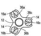
- FIG. 3Ais a cross-sectional view of the system for a single blade and its protective sheath as seen along the line 3 - 3 in FIG. 1 ;
- FIG. 3Bis a cross-sectional view of the system for a plurality of blades and their respective protective sheaths as would be seen along the line 3 - 3 in FIG. 1 ;
- FIG. 4is a perspective view of the cutting blade balloon catheter system shown in FIG. 1 , with the balloon in an inflated configuration;
- FIG. 5is a partial cross-sectional view of the system as seen along the line 5 - 5 in FIG. 4 ;
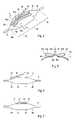
- FIG. 6is a side elevation view of a preferred embodiment of the present invention.
- FIG. 7is a side elevation view of an alternate embodiment of the present invention.
- FIG. 1A system in accordance with the present invention is shown in FIG. 1 and is generally designated 10 .
- the system 10includes a catheter 12 and has a balloon 14 that is mounted on the catheter 12 .
- the system 10includes a sheath (elongated member) 16 that is bonded to the balloon 14 in a manner well known in the pertinent art, such as by solvent bonding.
- the sheath 16is made of a polymer material of a type well known in the art.
- the catheter 12is formed with a so-called “pig tail” tip 18 that can be used to facilitate the maneuvering of the catheter 12 within the vasculature of a patient (not shown).
- catheter 12is shown to include a radiopaque marker 20 for locating the catheter 12 once it is in the vasculature.
- FIG. 1also indicates that an extracorporeal fluid pump 22 is connected in fluid communication with the balloon 14 to selectively inflate and deflate the balloon 14 .
- an extracorporeal fluid pump 22is connected in fluid communication with the balloon 14 to selectively inflate and deflate the balloon 14 .
- the structure of sheath 16will be best appreciated by referencing FIG. 2 .
- the sheath (elongated member) 16is effectively bifurcated into two halves 24 a and 24 b .
- the sheath 16is generally a tube shaped structure that defines a longitudinal axis 26 .
- the sheath 16is divided by a slit 28 and is formed with a protective channel 30 .
- both the slit 28 and the protective channel 30extend lengthwise along the sheath 16 in a longitudinal direction.
- the slit 28extends radially from the axis 26 and lies in a longitudinal plane that is generally defined by the axis 26 and the slit 28 .
- the slit 28extends from a vertex 32 to the outer surface 34 of the sheath 16 wherein the vertex 32 is substantially parallel to the axis 26 and is in the longitudinal plane.
- the protective channel 30 of sheath 16is diametrically opposed to the slit 28 .
- the protective channel 30extends from the vertex 32 to the outer surface 34 .
- the dimensions of the protective channel 30are established to conform the channel 30 to the dimensions of a blade 36 .
- the protective channel 30is formed to receive the blade 36 therein, such as is shown for the phantom blade 36 ′ in FIG. 2 .
- the blade 36will be preferably made of a stainless steel and will be approximately twenty-five millimeters in length.
- the sheath 16has a bonding area 38 a on the half 24 a , and a similar bonding area 38 b on the half 24 b . Both of these bonding areas 38 a and 38 b are located on the outer surface 34 of the sheath 16 and extend along the length of the sheath 16 . Further, these bonding areas 38 a and 38 b extend on the surface 34 through an arc length 40 that is approximately ninety degrees, or more.
- An adhesive that is placed on the bonding areas 38 a and 38 bbonds the sheath 16 to the balloon 14 . More specifically, this is done with the blade 36 also bonded to the balloon 14 and with the blade 36 positioned inside the protective channel 30 .
- the outer surface 34 of the sheath 16remains bonded to the balloon 14 at the bonding areas 38 a and 38 b . Likewise, the blade 36 also remains operationally bonded to the balloon 14 .
- the sheath 16effectively holds and covers the blade 36 in its protective channel 30 . Further, in this configuration, the sheath 16 also helps define folds for the deflated balloon 14 that reduce the profile of balloon 14 , and thereby facilitate the maneuvering of the catheter 12 through the vasculature. As indicated by FIG. 3B , although the disclosure here is directed toward a single sheath 16 and blade 36 combination, the present invention also contemplates the use of a plurality of such combinations. The combinations of multi-blades 36 a,b,c and respective multi sheaths 16 a,b,c shown in FIG. 3B are only exemplary.
- a proximal portion 42As shown in FIG. 4 , after the balloon 14 has been inflated by pump 22 , it has three definable portions. These are: a proximal portion 42 ; and intermediate portion 44 ; and a distal portion 46 .
- the intermediate portion 44is substantially cylindrical shaped.
- both the proximal portion 42 and the distal portion 46are conical shaped.
- the proximal portion 42is characterized by a taper having a decreasing diameter in the proximal direction.
- the catheter 12 and balloon 14are advanced into the vasculature of a patient. Accordingly, the sheath 16 and blade 36 that are respectively attached to the balloon 14 as disclosed above are also advanced into the vasculature. This is done while the balloon 14 is in its deflated configuration (see FIG. 1 ). Once the system 10 has been advanced into the vasculature, the balloon 14 can be selectively inflated into its inflated configuration (see FIG. 4 ).
- inflating balloon 14is perhaps best appreciated by cross-referencing FIG. 3A (deflated configuration) with FIG. 4 (inflated configuration). This appreciation may be further enhanced by also referencing FIG. 5 .
- the halves 24 a and 24 b of the sheath 16are separated from each other. Recall, the halves 24 a and 24 b are individually bonded to the surface of the balloon 14 . Accordingly, because this fixed relationship between balloon 14 and the halves 24 a and 24 b has been previously established, and is maintained, the reconfiguration of balloon 14 (i.e. the inflation of balloon 14 ) causes the respective halves 24 a and 24 b to separate.
- FIG. 1when the balloon 14 is deflated
- the sides 48 a and 48 b of slit 28are juxtaposed with each other to confine and cover the blade 36 in the protective channel 30 of sheath 16 .
- balloon 14is inflated ( FIGS. 4 and 5 )
- the slit sides 48 a and 48 bare separated from each other.
- the sides 50 a and 50 b of protective channel 30are distanced from the blade 36 . The result of all this is that the blade 36 is exposed for operational use as desired.
- the balloon 14may be deflated by appropriately manipulating the pump 22 . This causes the balloon 14 to return from its inflated configuration ( FIG. 4 ) to its deflated configuration ( FIGS. 1 and 3A ). As implied above, during this deflation, the interaction between the sheath 16 and the balloon 14 will cause the balloon 14 to advantageously fold along predetermined fold lines. Also, the blade 36 will again be enclosed within the protective channel 30 as the system 10 is safely withdrawn from the vasculature of a patient.
- a preferred embodiment for the system 10provides for a tilting blade 36 (see FIGS. 4 and 6 ).
- a proximal segment 52 of the blade 36is bonded to the proximal portion 42 of the balloon 14
- a distal segment 54 of the blade 36is not. Consequently, because the distal segment 54 of blade 36 is not bonded to the balloon 14 , the blade 36 will follow the taper of proximal portion 42 . Thus, the distal segment 54 of blade 36 will extend radially from the balloon 14 .
- the distal segment 54will, however, be enclosed in the protective channel 30 and covered by sheath 16 , as disclosed above, whenever balloon 14 is deflated.
- the blade 36 and sheath 16may be mounted directly onto the intermediate portion 44 of balloon 14 . In this case, the entire blade 36 will move through a same radial distance as the balloon 14 is inflated.
Landscapes
- Health & Medical Sciences (AREA)
- Surgery (AREA)
- Life Sciences & Earth Sciences (AREA)
- Biomedical Technology (AREA)
- Nuclear Medicine, Radiotherapy & Molecular Imaging (AREA)
- Engineering & Computer Science (AREA)
- Vascular Medicine (AREA)
- Heart & Thoracic Surgery (AREA)
- Medical Informatics (AREA)
- Molecular Biology (AREA)
- Animal Behavior & Ethology (AREA)
- General Health & Medical Sciences (AREA)
- Public Health (AREA)
- Veterinary Medicine (AREA)
- Media Introduction/Drainage Providing Device (AREA)
Abstract
Description
Claims (20)
Priority Applications (2)
| Application Number | Priority Date | Filing Date | Title |
|---|---|---|---|
| US10/742,166US7338463B2 (en) | 2003-12-19 | 2003-12-19 | Balloon blade sheath |
| US10/848,270US7413558B2 (en) | 2003-12-19 | 2004-05-18 | Elastically distensible folding member |
Applications Claiming Priority (1)
| Application Number | Priority Date | Filing Date | Title |
|---|---|---|---|
| US10/742,166US7338463B2 (en) | 2003-12-19 | 2003-12-19 | Balloon blade sheath |
Related Child Applications (1)
| Application Number | Title | Priority Date | Filing Date |
|---|---|---|---|
| US10/848,270Continuation-In-PartUS7413558B2 (en) | 2003-12-19 | 2004-05-18 | Elastically distensible folding member |
Publications (2)
| Publication Number | Publication Date |
|---|---|
| US20050137616A1 US20050137616A1 (en) | 2005-06-23 |
| US7338463B2true US7338463B2 (en) | 2008-03-04 |
Family
ID=34678381
Family Applications (1)
| Application Number | Title | Priority Date | Filing Date |
|---|---|---|---|
| US10/742,166Expired - LifetimeUS7338463B2 (en) | 2003-12-19 | 2003-12-19 | Balloon blade sheath |
Country Status (1)
| Country | Link |
|---|---|
| US (1) | US7338463B2 (en) |
Cited By (44)
| Publication number | Priority date | Publication date | Assignee | Title |
|---|---|---|---|---|
| US20070129723A1 (en)* | 2005-12-01 | 2007-06-07 | Ethicon Endo-Surgery, Inc. | Ultrasonic medical instrument and medical instrument connection assembly |
| US20070167965A1 (en)* | 2006-01-05 | 2007-07-19 | Ethicon Endo-Surgery, Inc. | Ultrasonic medical instrument |
| US20070173871A1 (en)* | 2006-01-20 | 2007-07-26 | Houser Kevin L | Ultrasound medical instrument having a medical ultrasonic blade |
| US20070173872A1 (en)* | 2006-01-23 | 2007-07-26 | Ethicon Endo-Surgery, Inc. | Surgical instrument for cutting and coagulating patient tissue |
| US20070191712A1 (en)* | 2006-02-15 | 2007-08-16 | Ethicon Endo-Surgery, Inc. | Method for sealing a blood vessel, a medical system and a medical instrument |
| US20070191828A1 (en)* | 2006-02-16 | 2007-08-16 | Ethicon Endo-Surgery, Inc. | Energy-based medical treatment system and method |
| US20080228136A1 (en)* | 2006-09-21 | 2008-09-18 | Mercator Medsystems, Inc. | Dual modulus balloon for interventional procedures |
| US20090306582A1 (en)* | 2008-06-10 | 2009-12-10 | Bavaria Medizin Technologie Gmbh | Scoring catheter and method for treating diseased heart valves |
| US8192675B2 (en) | 2008-03-13 | 2012-06-05 | Cook Medical Technologies Llc | Cutting balloon with connector and dilation element |
| US8491615B2 (en)* | 2010-12-29 | 2013-07-23 | Boston Scientific Scimed, Inc. | Cutting balloon catheter |
| US20140128895A1 (en)* | 2004-11-12 | 2014-05-08 | Boston Scientific Scimed, Inc. | Cutting balloon catheter having flexible atherotomes |
| US8986248B2 (en) | 2004-06-23 | 2015-03-24 | Boston Scientific Scimed, Inc. | Cutting balloon and process |
| US9956384B2 (en) | 2014-01-24 | 2018-05-01 | Cook Medical Technologies Llc | Articulating balloon catheter and method for using the same |
| US10286190B2 (en) | 2013-12-11 | 2019-05-14 | Cook Medical Technologies Llc | Balloon catheter with dynamic vessel engaging member |
| US10335189B2 (en) | 2014-12-03 | 2019-07-02 | PAVmed Inc. | Systems and methods for percutaneous division of fibrous structures |
| US10828057B2 (en) | 2007-03-22 | 2020-11-10 | Ethicon Llc | Ultrasonic surgical instruments |
| US10835768B2 (en) | 2010-02-11 | 2020-11-17 | Ethicon Llc | Dual purpose surgical instrument for cutting and coagulating tissue |
| US10874418B2 (en) | 2004-02-27 | 2020-12-29 | Ethicon Llc | Ultrasonic surgical shears and method for sealing a blood vessel using same |
| US10952759B2 (en) | 2016-08-25 | 2021-03-23 | Ethicon Llc | Tissue loading of a surgical instrument |
| US10966744B2 (en) | 2016-07-12 | 2021-04-06 | Ethicon Llc | Ultrasonic surgical instrument with piezoelectric central lumen transducer |
| US20210113820A1 (en)* | 2018-07-09 | 2021-04-22 | Goodman Co., Ltd. | Balloon catheter |
| US11000707B2 (en) | 2009-06-24 | 2021-05-11 | Ethicon Llc | Ultrasonic surgical instruments |
| US11006971B2 (en) | 2004-10-08 | 2021-05-18 | Ethicon Llc | Actuation mechanism for use with an ultrasonic surgical instrument |
| US20210153891A1 (en)* | 2019-11-27 | 2021-05-27 | Boston Scientific Scimed, Inc. | Cutting balloon catheter |
| US11020140B2 (en) | 2015-06-17 | 2021-06-01 | Cilag Gmbh International | Ultrasonic surgical blade for use with ultrasonic surgical instruments |
| US11033292B2 (en) | 2013-12-16 | 2021-06-15 | Cilag Gmbh International | Medical device |
| USD924400S1 (en) | 2016-08-16 | 2021-07-06 | Cilag Gmbh International | Surgical instrument |
| US11058447B2 (en) | 2007-07-31 | 2021-07-13 | Cilag Gmbh International | Temperature controlled ultrasonic surgical instruments |
| US11154320B2 (en) | 2018-04-09 | 2021-10-26 | Boston Scientific Scimed, Inc. | Cutting balloon basket |
| US11253288B2 (en) | 2007-11-30 | 2022-02-22 | Cilag Gmbh International | Ultrasonic surgical instrument blades |
| US11272952B2 (en) | 2013-03-14 | 2022-03-15 | Cilag Gmbh International | Mechanical fasteners for use with surgical energy devices |
| US11350959B2 (en) | 2016-08-25 | 2022-06-07 | Cilag Gmbh International | Ultrasonic transducer techniques for ultrasonic surgical instrument |
| US11369402B2 (en) | 2010-02-11 | 2022-06-28 | Cilag Gmbh International | Control systems for ultrasonically powered surgical instruments |
| US11439426B2 (en) | 2007-11-30 | 2022-09-13 | Cilag Gmbh International | Ultrasonic surgical blades |
| US11553954B2 (en) | 2015-06-30 | 2023-01-17 | Cilag Gmbh International | Translatable outer tube for sealing using shielded lap chole dissector |
| US11602371B2 (en) | 2012-06-29 | 2023-03-14 | Cilag Gmbh International | Ultrasonic surgical instruments with control mechanisms |
| US11607268B2 (en) | 2007-07-27 | 2023-03-21 | Cilag Gmbh International | Surgical instruments |
| US11654267B2 (en) | 2018-03-14 | 2023-05-23 | Mercator Medsystems, Inc. | Medical instrument and medical method for localized drug delivery |
| US11666784B2 (en) | 2007-07-31 | 2023-06-06 | Cilag Gmbh International | Surgical instruments |
| US11690641B2 (en) | 2007-07-27 | 2023-07-04 | Cilag Gmbh International | Ultrasonic end effectors with increased active length |
| US11849967B2 (en) | 2019-03-26 | 2023-12-26 | Terumo Kabushiki Kaisha | Scoring device and treatment method |
| US11877734B2 (en) | 2007-07-31 | 2024-01-23 | Cilag Gmbh International | Ultrasonic surgical instruments |
| US11998229B2 (en) | 2005-10-14 | 2024-06-04 | Cilag Gmbh International | Ultrasonic device for cutting and coagulating |
| US12156693B2 (en) | 2020-05-27 | 2024-12-03 | PAVmed Inc. | Systems and methods for minimally-invasive division of fibrous structures |
Families Citing this family (8)
| Publication number | Priority date | Publication date | Assignee | Title |
|---|---|---|---|---|
| US7270673B2 (en)* | 2003-12-31 | 2007-09-18 | Boston Scientific Scimed, Inc. | Microsurgical balloon with protective reinforcement |
| US7976541B2 (en)* | 2006-02-15 | 2011-07-12 | Boston Scientific Scimed, Inc. | Contact sensitive probes with indicators |
| US7842056B2 (en)* | 2007-05-18 | 2010-11-30 | Boston Scientific Scimed, Inc. | Cutting member for bifurcation catheter assembly |
| EP2172242A1 (en)* | 2008-10-03 | 2010-04-07 | National University of Ireland Galway | Intravascular Treatment Device |
| US9186129B2 (en)* | 2011-05-26 | 2015-11-17 | Adn International, Llc | Expandable device for tissue collection from an aerodigestive body lumen |
| US9861444B2 (en)* | 2011-11-01 | 2018-01-09 | The Johns Hopkins University | Method and device for endoscopic abrasion |
| JP2016013215A (en)* | 2014-07-01 | 2016-01-28 | 朝日インテック株式会社 | Balloon catheter |
| CN115317766B (en)* | 2022-08-18 | 2023-03-28 | 广东博迈医疗科技股份有限公司 | Cutting balloon catheter with hidden blades |
Citations (35)
| Publication number | Priority date | Publication date | Assignee | Title |
|---|---|---|---|---|
| US4685458A (en) | 1984-03-01 | 1987-08-11 | Vaser, Inc. | Angioplasty catheter and method for use thereof |
| US4710181A (en) | 1985-06-11 | 1987-12-01 | Genus Catheter Technologies, Inc. | Variable diameter catheter |
| US4966604A (en) | 1989-01-23 | 1990-10-30 | Interventional Technologies Inc. | Expandable atherectomy cutter with flexibly bowed blades |
| US5042985A (en) | 1989-05-11 | 1991-08-27 | Advanced Cardiovascular Systems, Inc. | Dilatation catheter suitable for peripheral arteries |
| US5053044A (en) | 1988-01-11 | 1991-10-01 | Devices For Vascular Intervention, Inc. | Catheter and method for making intravascular incisions |
| US5074841A (en) | 1990-01-30 | 1991-12-24 | Microcision, Inc. | Atherectomy device with helical cutter |
| US5078725A (en) | 1989-11-09 | 1992-01-07 | C. R. Bard, Inc. | Balloon catheter and techniques for dilating obstructed lumens and other luminal procedures |
| US5092873A (en) | 1990-02-28 | 1992-03-03 | Devices For Vascular Intervention, Inc. | Balloon configuration for atherectomy catheter |
| US5092872A (en) | 1989-07-28 | 1992-03-03 | Jacob Segalowitz | Valvulotome catheter |
| US5116318A (en) | 1989-06-06 | 1992-05-26 | Cordis Corporation | Dilatation balloon within an elastic sleeve |
| US5156610A (en) | 1989-08-18 | 1992-10-20 | Evi Corporation | Catheter atherotome |
| US5176693A (en) | 1992-05-11 | 1993-01-05 | Interventional Technologies, Inc. | Balloon expandable atherectomy cutter |
| US5222966A (en) | 1990-02-28 | 1993-06-29 | Devices For Vascular Intervention, Inc. | Balloon connection and inflation lumen for atherectomy catheter |
| US5224949A (en) | 1992-01-13 | 1993-07-06 | Interventional Technologies, Inc. | Camming device |
| US5320634A (en) | 1990-07-03 | 1994-06-14 | Interventional Technologies, Inc. | Balloon catheter with seated cutting edges |
| US5372601A (en) | 1993-03-30 | 1994-12-13 | Lary; Banning G. | Longitudinal reciprocating incisor |
| US5403334A (en) | 1989-09-12 | 1995-04-04 | Devices For Vascular Intervention, Inc. | Atherectomy device having helical blade and blade guide |
| US5556405A (en) | 1995-10-13 | 1996-09-17 | Interventional Technologies Inc. | Universal dilator with reciprocal incisor |
| US5616149A (en) | 1990-07-03 | 1997-04-01 | Cedars-Sinai Medical Center | Balloon catheter with cutting edge |
| US5697944A (en) | 1995-11-15 | 1997-12-16 | Interventional Technologies Inc. | Universal dilator with expandable incisor |
| US5713913A (en) | 1996-11-12 | 1998-02-03 | Interventional Technologies Inc. | Device and method for transecting a coronary artery |
| US5728123A (en) | 1995-04-26 | 1998-03-17 | Lemelson; Jerome H. | Balloon actuated catheter |
| US5792158A (en)* | 1995-11-15 | 1998-08-11 | Lary; Banning Gray | University dilator with expandable incisor |
| US5797935A (en) | 1996-09-26 | 1998-08-25 | Interventional Technologies Inc. | Balloon activated forced concentrators for incising stenotic segments |
| US5941869A (en) | 1997-02-12 | 1999-08-24 | Prolifix Medical, Inc. | Apparatus and method for controlled removal of stenotic material from stents |
| US6090135A (en) | 1993-06-07 | 2000-07-18 | Endovascular Instruments, Inc. | Anti-stenotic method and product for occluded and partially occluded arteries |
| US6110192A (en) | 1996-09-23 | 2000-08-29 | Boston Scientific Corporation | Catheter balloon having raised radial segments |
| US6258108B1 (en) | 1996-09-13 | 2001-07-10 | Interventional Technologies, Inc. | Incisor-dilator with tapered balloon |
| US6306151B1 (en) | 1998-03-31 | 2001-10-23 | Interventional Technologies Inc. | Balloon with reciprocating stent incisor |
| US6309399B1 (en) | 1996-07-17 | 2001-10-30 | Scimed Life Systems, Inc. | Atherectomy device having trapping and excising means for removal of plaque from the aorta and other arteries |
| US6488693B2 (en) | 2000-01-26 | 2002-12-03 | Hearport, Inc. | Vascular incisor and method |
| US6632231B2 (en) | 2001-08-23 | 2003-10-14 | Scimed Life Systems, Inc. | Segmented balloon catheter blade |
| US20040133223A1 (en)* | 2003-01-02 | 2004-07-08 | Jan Weber | Medical devices |
| US20050119678A1 (en)* | 2003-12-01 | 2005-06-02 | O'brien Dennis | Cutting balloon having sheathed incising elements |
| US20050149082A1 (en)* | 2003-12-31 | 2005-07-07 | Carl Yee | Microsurgical balloon with protective reinforcement |
- 2003
- 2003-12-19USUS10/742,166patent/US7338463B2/ennot_activeExpired - Lifetime
Patent Citations (35)
| Publication number | Priority date | Publication date | Assignee | Title |
|---|---|---|---|---|
| US4685458A (en) | 1984-03-01 | 1987-08-11 | Vaser, Inc. | Angioplasty catheter and method for use thereof |
| US4710181A (en) | 1985-06-11 | 1987-12-01 | Genus Catheter Technologies, Inc. | Variable diameter catheter |
| US5053044A (en) | 1988-01-11 | 1991-10-01 | Devices For Vascular Intervention, Inc. | Catheter and method for making intravascular incisions |
| US4966604A (en) | 1989-01-23 | 1990-10-30 | Interventional Technologies Inc. | Expandable atherectomy cutter with flexibly bowed blades |
| US5042985A (en) | 1989-05-11 | 1991-08-27 | Advanced Cardiovascular Systems, Inc. | Dilatation catheter suitable for peripheral arteries |
| US5116318A (en) | 1989-06-06 | 1992-05-26 | Cordis Corporation | Dilatation balloon within an elastic sleeve |
| US5092872A (en) | 1989-07-28 | 1992-03-03 | Jacob Segalowitz | Valvulotome catheter |
| US5156610A (en) | 1989-08-18 | 1992-10-20 | Evi Corporation | Catheter atherotome |
| US5403334A (en) | 1989-09-12 | 1995-04-04 | Devices For Vascular Intervention, Inc. | Atherectomy device having helical blade and blade guide |
| US5078725A (en) | 1989-11-09 | 1992-01-07 | C. R. Bard, Inc. | Balloon catheter and techniques for dilating obstructed lumens and other luminal procedures |
| US5074841A (en) | 1990-01-30 | 1991-12-24 | Microcision, Inc. | Atherectomy device with helical cutter |
| US5092873A (en) | 1990-02-28 | 1992-03-03 | Devices For Vascular Intervention, Inc. | Balloon configuration for atherectomy catheter |
| US5222966A (en) | 1990-02-28 | 1993-06-29 | Devices For Vascular Intervention, Inc. | Balloon connection and inflation lumen for atherectomy catheter |
| US5320634A (en) | 1990-07-03 | 1994-06-14 | Interventional Technologies, Inc. | Balloon catheter with seated cutting edges |
| US5616149A (en) | 1990-07-03 | 1997-04-01 | Cedars-Sinai Medical Center | Balloon catheter with cutting edge |
| US5224949A (en) | 1992-01-13 | 1993-07-06 | Interventional Technologies, Inc. | Camming device |
| US5176693A (en) | 1992-05-11 | 1993-01-05 | Interventional Technologies, Inc. | Balloon expandable atherectomy cutter |
| US5372601A (en) | 1993-03-30 | 1994-12-13 | Lary; Banning G. | Longitudinal reciprocating incisor |
| US6090135A (en) | 1993-06-07 | 2000-07-18 | Endovascular Instruments, Inc. | Anti-stenotic method and product for occluded and partially occluded arteries |
| US5728123A (en) | 1995-04-26 | 1998-03-17 | Lemelson; Jerome H. | Balloon actuated catheter |
| US5556405A (en) | 1995-10-13 | 1996-09-17 | Interventional Technologies Inc. | Universal dilator with reciprocal incisor |
| US5697944A (en) | 1995-11-15 | 1997-12-16 | Interventional Technologies Inc. | Universal dilator with expandable incisor |
| US5792158A (en)* | 1995-11-15 | 1998-08-11 | Lary; Banning Gray | University dilator with expandable incisor |
| US6309399B1 (en) | 1996-07-17 | 2001-10-30 | Scimed Life Systems, Inc. | Atherectomy device having trapping and excising means for removal of plaque from the aorta and other arteries |
| US6258108B1 (en) | 1996-09-13 | 2001-07-10 | Interventional Technologies, Inc. | Incisor-dilator with tapered balloon |
| US6110192A (en) | 1996-09-23 | 2000-08-29 | Boston Scientific Corporation | Catheter balloon having raised radial segments |
| US5797935A (en) | 1996-09-26 | 1998-08-25 | Interventional Technologies Inc. | Balloon activated forced concentrators for incising stenotic segments |
| US5713913A (en) | 1996-11-12 | 1998-02-03 | Interventional Technologies Inc. | Device and method for transecting a coronary artery |
| US5941869A (en) | 1997-02-12 | 1999-08-24 | Prolifix Medical, Inc. | Apparatus and method for controlled removal of stenotic material from stents |
| US6306151B1 (en) | 1998-03-31 | 2001-10-23 | Interventional Technologies Inc. | Balloon with reciprocating stent incisor |
| US6488693B2 (en) | 2000-01-26 | 2002-12-03 | Hearport, Inc. | Vascular incisor and method |
| US6632231B2 (en) | 2001-08-23 | 2003-10-14 | Scimed Life Systems, Inc. | Segmented balloon catheter blade |
| US20040133223A1 (en)* | 2003-01-02 | 2004-07-08 | Jan Weber | Medical devices |
| US20050119678A1 (en)* | 2003-12-01 | 2005-06-02 | O'brien Dennis | Cutting balloon having sheathed incising elements |
| US20050149082A1 (en)* | 2003-12-31 | 2005-07-07 | Carl Yee | Microsurgical balloon with protective reinforcement |
Cited By (86)
| Publication number | Priority date | Publication date | Assignee | Title |
|---|---|---|---|---|
| US10874418B2 (en) | 2004-02-27 | 2020-12-29 | Ethicon Llc | Ultrasonic surgical shears and method for sealing a blood vessel using same |
| US11730507B2 (en) | 2004-02-27 | 2023-08-22 | Cilag Gmbh International | Ultrasonic surgical shears and method for sealing a blood vessel using same |
| US8986248B2 (en) | 2004-06-23 | 2015-03-24 | Boston Scientific Scimed, Inc. | Cutting balloon and process |
| US11006971B2 (en) | 2004-10-08 | 2021-05-18 | Ethicon Llc | Actuation mechanism for use with an ultrasonic surgical instrument |
| US9603619B2 (en)* | 2004-11-12 | 2017-03-28 | Boston Scientific Scimed, Inc. | Cutting balloon catheter having flexible atherotomes |
| US20150196319A1 (en)* | 2004-11-12 | 2015-07-16 | Boston Scientific Scimed, Inc. | Cutting balloon catheter having flexible atherotomes |
| US9017353B2 (en)* | 2004-11-12 | 2015-04-28 | Boston Scientific Scimed, Inc. | Cutting balloon catheter having flexible atherotomes |
| US20140128895A1 (en)* | 2004-11-12 | 2014-05-08 | Boston Scientific Scimed, Inc. | Cutting balloon catheter having flexible atherotomes |
| US11998229B2 (en) | 2005-10-14 | 2024-06-04 | Cilag Gmbh International | Ultrasonic device for cutting and coagulating |
| US20070129723A1 (en)* | 2005-12-01 | 2007-06-07 | Ethicon Endo-Surgery, Inc. | Ultrasonic medical instrument and medical instrument connection assembly |
| US8246642B2 (en) | 2005-12-01 | 2012-08-21 | Ethicon Endo-Surgery, Inc. | Ultrasonic medical instrument and medical instrument connection assembly |
| US20070167965A1 (en)* | 2006-01-05 | 2007-07-19 | Ethicon Endo-Surgery, Inc. | Ultrasonic medical instrument |
| US20090131962A2 (en)* | 2006-01-20 | 2009-05-21 | Kevin Houser | Ultrasound Medical Instrument Having A Medical Ultrasonic Blade |
| US10779848B2 (en) | 2006-01-20 | 2020-09-22 | Ethicon Llc | Ultrasound medical instrument having a medical ultrasonic blade |
| US20070173871A1 (en)* | 2006-01-20 | 2007-07-26 | Houser Kevin L | Ultrasound medical instrument having a medical ultrasonic blade |
| US12042168B2 (en) | 2006-01-20 | 2024-07-23 | Cilag Gmbh International | Ultrasound medical instrument having a medical ultrasonic blade |
| US20100042126A1 (en)* | 2006-01-20 | 2010-02-18 | Houser Kevin L | Ultrasound medical instrument having a medical ultrasonic blade |
| US7621930B2 (en) | 2006-01-20 | 2009-11-24 | Ethicon Endo-Surgery, Inc. | Ultrasound medical instrument having a medical ultrasonic blade |
| US20070173872A1 (en)* | 2006-01-23 | 2007-07-26 | Ethicon Endo-Surgery, Inc. | Surgical instrument for cutting and coagulating patient tissue |
| US20070191712A1 (en)* | 2006-02-15 | 2007-08-16 | Ethicon Endo-Surgery, Inc. | Method for sealing a blood vessel, a medical system and a medical instrument |
| US7854735B2 (en) | 2006-02-16 | 2010-12-21 | Ethicon Endo-Surgery, Inc. | Energy-based medical treatment system and method |
| US20070191828A1 (en)* | 2006-02-16 | 2007-08-16 | Ethicon Endo-Surgery, Inc. | Energy-based medical treatment system and method |
| US8016786B2 (en) | 2006-09-21 | 2011-09-13 | Mercator Medsystems, Inc. | Dual modulus balloon for interventional procedures |
| US10561816B2 (en) | 2006-09-21 | 2020-02-18 | Mercator Medsystems, Inc. | Dual modulus balloon for interventional procedures |
| US9789276B2 (en) | 2006-09-21 | 2017-10-17 | Mercator Medsystems, Inc. | Dual modulus balloon for interventional procedures |
| US8721590B2 (en) | 2006-09-21 | 2014-05-13 | Mercator Medsystems, Inc. | Dual modulus balloon for interventional procedures |
| US20080228136A1 (en)* | 2006-09-21 | 2008-09-18 | Mercator Medsystems, Inc. | Dual modulus balloon for interventional procedures |
| US7691080B2 (en)* | 2006-09-21 | 2010-04-06 | Mercator Medsystems, Inc. | Dual modulus balloon for interventional procedures |
| US10828057B2 (en) | 2007-03-22 | 2020-11-10 | Ethicon Llc | Ultrasonic surgical instruments |
| US11690641B2 (en) | 2007-07-27 | 2023-07-04 | Cilag Gmbh International | Ultrasonic end effectors with increased active length |
| US12324602B2 (en) | 2007-07-27 | 2025-06-10 | Cilag Gmbh International | Ultrasonic end effectors with increased active length |
| US11607268B2 (en) | 2007-07-27 | 2023-03-21 | Cilag Gmbh International | Surgical instruments |
| US11666784B2 (en) | 2007-07-31 | 2023-06-06 | Cilag Gmbh International | Surgical instruments |
| US11058447B2 (en) | 2007-07-31 | 2021-07-13 | Cilag Gmbh International | Temperature controlled ultrasonic surgical instruments |
| US12220143B2 (en) | 2007-07-31 | 2025-02-11 | Cilag Gmbh International | Temperature controlled ultrasonic surgical instruments |
| US12268900B2 (en) | 2007-07-31 | 2025-04-08 | Cilag Gmbh International | Surgical instruments |
| US11877734B2 (en) | 2007-07-31 | 2024-01-23 | Cilag Gmbh International | Ultrasonic surgical instruments |
| US12383296B2 (en) | 2007-11-30 | 2025-08-12 | Cilag Gmbh International | Ultrasonic surgical instrument blades |
| US11439426B2 (en) | 2007-11-30 | 2022-09-13 | Cilag Gmbh International | Ultrasonic surgical blades |
| US11253288B2 (en) | 2007-11-30 | 2022-02-22 | Cilag Gmbh International | Ultrasonic surgical instrument blades |
| US12369939B2 (en) | 2007-11-30 | 2025-07-29 | Cilag Gmbh International | Ultrasonic surgical blades |
| US11266433B2 (en) | 2007-11-30 | 2022-03-08 | Cilag Gmbh International | Ultrasonic surgical instrument blades |
| US11766276B2 (en) | 2007-11-30 | 2023-09-26 | Cilag Gmbh International | Ultrasonic surgical blades |
| US11690643B2 (en) | 2007-11-30 | 2023-07-04 | Cilag Gmbh International | Ultrasonic surgical blades |
| US8192675B2 (en) | 2008-03-13 | 2012-06-05 | Cook Medical Technologies Llc | Cutting balloon with connector and dilation element |
| US10016212B2 (en) | 2008-03-13 | 2018-07-10 | Cook Medical Technologies Llc | Cutting balloon with connector and dilation element |
| US9604036B2 (en) | 2008-03-13 | 2017-03-28 | Cook Medical Technologies Llc | Cutting balloon with connector and dilation element |
| US10617443B2 (en) | 2008-03-13 | 2020-04-14 | Cook Medical Technologies Llc | Cutting balloon with connector and dilation element |
| US8398662B2 (en)* | 2008-06-10 | 2013-03-19 | Bavaria Medizin Technologie Gmbh | Scoring catheter and method for treating diseased heart valves |
| US20090306582A1 (en)* | 2008-06-10 | 2009-12-10 | Bavaria Medizin Technologie Gmbh | Scoring catheter and method for treating diseased heart valves |
| US11000707B2 (en) | 2009-06-24 | 2021-05-11 | Ethicon Llc | Ultrasonic surgical instruments |
| US11179582B2 (en) | 2009-06-24 | 2021-11-23 | Cilag Gmbh International | Ultrasonic surgical instruments |
| US11369402B2 (en) | 2010-02-11 | 2022-06-28 | Cilag Gmbh International | Control systems for ultrasonically powered surgical instruments |
| US10835768B2 (en) | 2010-02-11 | 2020-11-17 | Ethicon Llc | Dual purpose surgical instrument for cutting and coagulating tissue |
| US8491615B2 (en)* | 2010-12-29 | 2013-07-23 | Boston Scientific Scimed, Inc. | Cutting balloon catheter |
| US10729893B2 (en) | 2010-12-29 | 2020-08-04 | Boston Scientific Scimed, Inc. | Cutting balloon catheter |
| US9302071B2 (en) | 2010-12-29 | 2016-04-05 | Boston Scientific Scimed, Inc. | Cutting balloon catheter |
| US10046146B2 (en) | 2010-12-29 | 2018-08-14 | Boston Scientific Scimed, Inc. | Cutting balloon catheter |
| US11602371B2 (en) | 2012-06-29 | 2023-03-14 | Cilag Gmbh International | Ultrasonic surgical instruments with control mechanisms |
| US11272952B2 (en) | 2013-03-14 | 2022-03-15 | Cilag Gmbh International | Mechanical fasteners for use with surgical energy devices |
| US10286190B2 (en) | 2013-12-11 | 2019-05-14 | Cook Medical Technologies Llc | Balloon catheter with dynamic vessel engaging member |
| US11033292B2 (en) | 2013-12-16 | 2021-06-15 | Cilag Gmbh International | Medical device |
| US9956384B2 (en) | 2014-01-24 | 2018-05-01 | Cook Medical Technologies Llc | Articulating balloon catheter and method for using the same |
| US11259837B2 (en) | 2014-12-03 | 2022-03-01 | PAVmed Inc. | Systems and methods for percutaneous division of fibrous structures |
| US10335189B2 (en) | 2014-12-03 | 2019-07-02 | PAVmed Inc. | Systems and methods for percutaneous division of fibrous structures |
| US11141186B2 (en) | 2014-12-03 | 2021-10-12 | PAVmed Inc. | Systems and methods for percutaneous division of fibrous structures |
| US12114888B2 (en) | 2014-12-03 | 2024-10-15 | PAVmed Inc. | Systems and methods for percutaneous division of fibrous structures |
| US11020140B2 (en) | 2015-06-17 | 2021-06-01 | Cilag Gmbh International | Ultrasonic surgical blade for use with ultrasonic surgical instruments |
| US12156674B2 (en) | 2015-06-17 | 2024-12-03 | Cilag Gmbh International | Ultrasonic surgical blade for use with ultrasonic surgical instruments |
| US11553954B2 (en) | 2015-06-30 | 2023-01-17 | Cilag Gmbh International | Translatable outer tube for sealing using shielded lap chole dissector |
| US10966744B2 (en) | 2016-07-12 | 2021-04-06 | Ethicon Llc | Ultrasonic surgical instrument with piezoelectric central lumen transducer |
| US11883055B2 (en) | 2016-07-12 | 2024-01-30 | Cilag Gmbh International | Ultrasonic surgical instrument with piezoelectric central lumen transducer |
| USD924400S1 (en) | 2016-08-16 | 2021-07-06 | Cilag Gmbh International | Surgical instrument |
| USD1049376S1 (en) | 2016-08-16 | 2024-10-29 | Cilag Gmbh International | Surgical instrument |
| US10952759B2 (en) | 2016-08-25 | 2021-03-23 | Ethicon Llc | Tissue loading of a surgical instrument |
| US11925378B2 (en) | 2016-08-25 | 2024-03-12 | Cilag Gmbh International | Ultrasonic transducer for surgical instrument |
| US11350959B2 (en) | 2016-08-25 | 2022-06-07 | Cilag Gmbh International | Ultrasonic transducer techniques for ultrasonic surgical instrument |
| US11654267B2 (en) | 2018-03-14 | 2023-05-23 | Mercator Medsystems, Inc. | Medical instrument and medical method for localized drug delivery |
| US11801067B2 (en) | 2018-04-09 | 2023-10-31 | Boston Scientific Scimed, Inc. | Cutting balloon basket |
| US11154320B2 (en) | 2018-04-09 | 2021-10-26 | Boston Scientific Scimed, Inc. | Cutting balloon basket |
| US12042613B2 (en)* | 2018-07-09 | 2024-07-23 | Goodman Co., Ltd. | Balloon catheter |
| US20210113820A1 (en)* | 2018-07-09 | 2021-04-22 | Goodman Co., Ltd. | Balloon catheter |
| US11849967B2 (en) | 2019-03-26 | 2023-12-26 | Terumo Kabushiki Kaisha | Scoring device and treatment method |
| US20210153891A1 (en)* | 2019-11-27 | 2021-05-27 | Boston Scientific Scimed, Inc. | Cutting balloon catheter |
| US11812987B2 (en)* | 2019-11-27 | 2023-11-14 | Boston Scientific Scimed, Inc. | Cutting balloon catheter |
| US12156693B2 (en) | 2020-05-27 | 2024-12-03 | PAVmed Inc. | Systems and methods for minimally-invasive division of fibrous structures |
Also Published As
| Publication number | Publication date |
|---|---|
| US20050137616A1 (en) | 2005-06-23 |
Similar Documents
| Publication | Publication Date | Title |
|---|---|---|
| US7338463B2 (en) | Balloon blade sheath | |
| EP3244814B1 (en) | Intravascular catheter balloon device having a tool for atherectomy or an incising portion for atheromatous plaque scoring | |
| US7799043B2 (en) | Cutting balloon having sheathed incising elements | |
| US5836957A (en) | Large volume atherectomy device | |
| US5643296A (en) | Intravascular catheter with guiding structure | |
| US5092873A (en) | Balloon configuration for atherectomy catheter | |
| CA1286186C (en) | Single lumen atherectomy catheter device | |
| EP1480709B1 (en) | Balloon catheter for creating a longitudinal channel in a lesion and method | |
| US5071425A (en) | Atherectomy catheter and method of forming the same | |
| US5222966A (en) | Balloon connection and inflation lumen for atherectomy catheter | |
| US20200060716A1 (en) | Tissue-removing catheter with adjustable cross-sectional dimension | |
| AU668519B2 (en) | Stenotic dilatation device | |
| US5632754A (en) | Universal catheter with interchangeable work element | |
| JP2682831B2 (en) | Small inflation catheter filled with liquid | |
| US4867156A (en) | Percutaneous axial atheroectomy catheter assembly and method of using the same | |
| US20030144677A1 (en) | Reciprocating cutting and dilating balloon | |
| JPH07255737A (en) | Expandable laser catheter | |
| EP0708668A1 (en) | Sheath for a balloon catheter | |
| JPH09501852A (en) | Dilatation catheter with eccentric balloon | |
| JPH10507949A (en) | Low profile balloon, wire catheter having a moldable and / or bendable tip | |
| JPH0613036B2 (en) | Atheroma removal device | |
| JPH02224767A (en) | Operable type expansion cathetel | |
| US11950800B2 (en) | Catheter with guided, translatable cutter for active slicing/scoring and related methods | |
| US20220039827A1 (en) | Endovascular cutting apparatus | |
| US20230285717A1 (en) | Dual function balloon catheter for crossing a lesion and performing percutaneous transluminal angioplasty |
Legal Events
| Date | Code | Title | Description |
|---|---|---|---|
| AS | Assignment | Owner name:SCIMED LIFE SYSTEMS, INC., MINNESOTA Free format text:ASSIGNMENT OF ASSIGNORS INTEREST;ASSIGNOR:VIGIL, DENNIS M.;REEL/FRAME:015226/0516 Effective date:20031125 | |
| AS | Assignment | Owner name:BOSTON SCIENTIFIC SCIMED, INC., MINNESOTA Free format text:CHANGE OF NAME;ASSIGNOR:SCIMED LIFE SYSTEMS, INC.;REEL/FRAME:018505/0868 Effective date:20050101 Owner name:BOSTON SCIENTIFIC SCIMED, INC.,MINNESOTA Free format text:CHANGE OF NAME;ASSIGNOR:SCIMED LIFE SYSTEMS, INC.;REEL/FRAME:018505/0868 Effective date:20050101 | |
| FEPP | Fee payment procedure | Free format text:PAYOR NUMBER ASSIGNED (ORIGINAL EVENT CODE: ASPN); ENTITY STATUS OF PATENT OWNER: LARGE ENTITY | |
| STCF | Information on status: patent grant | Free format text:PATENTED CASE | |
| FEPP | Fee payment procedure | Free format text:PAYER NUMBER DE-ASSIGNED (ORIGINAL EVENT CODE: RMPN); ENTITY STATUS OF PATENT OWNER: LARGE ENTITY Free format text:PAYOR NUMBER ASSIGNED (ORIGINAL EVENT CODE: ASPN); ENTITY STATUS OF PATENT OWNER: LARGE ENTITY | |
| FPAY | Fee payment | Year of fee payment:4 | |
| FPAY | Fee payment | Year of fee payment:8 | |
| MAFP | Maintenance fee payment | Free format text:PAYMENT OF MAINTENANCE FEE, 12TH YEAR, LARGE ENTITY (ORIGINAL EVENT CODE: M1553); ENTITY STATUS OF PATENT OWNER: LARGE ENTITY Year of fee payment:12 |