US7337781B2 - Implant for tongue - Google Patents
Implant for tongueDownload PDFInfo
- Publication number
- US7337781B2 US7337781B2US11/107,160US10716005AUS7337781B2US 7337781 B2US7337781 B2US 7337781B2US 10716005 AUS10716005 AUS 10716005AUS 7337781 B2US7337781 B2US 7337781B2
- Authority
- US
- United States
- Prior art keywords
- tongue
- brace
- patient
- implant
- retaining member
- Prior art date
- Legal status (The legal status is an assumption and is not a legal conclusion. Google has not performed a legal analysis and makes no representation as to the accuracy of the status listed.)
- Active, expires
Links
- 239000007943implantSubstances0.000titleclaimsabstractdescription96
- 210000003205muscleAnatomy0.000claimsabstractdescription52
- 238000000034methodMethods0.000claimsabstractdescription33
- 208000001797obstructive sleep apneaDiseases0.000claimsabstractdescription17
- 210000001519tissueAnatomy0.000claimsdescription83
- 230000008878couplingEffects0.000claimsdescription11
- 238000010168coupling processMethods0.000claimsdescription11
- 238000005859coupling reactionMethods0.000claimsdescription11
- 230000015572biosynthetic processEffects0.000claimsdescription6
- 230000005012migrationEffects0.000claimsdescription4
- 238000013508migrationMethods0.000claimsdescription4
- 230000014759maintenance of locationEffects0.000claims1
- 210000002105tongueAnatomy0.000description137
- 230000006835compressionEffects0.000description21
- 238000007906compressionMethods0.000description21
- 238000002679ablationMethods0.000description20
- 239000000463materialSubstances0.000description20
- 210000001584soft palateAnatomy0.000description16
- 238000002955isolationMethods0.000description14
- 210000003823hyoid boneAnatomy0.000description12
- 230000033001locomotionEffects0.000description10
- 238000002513implantationMethods0.000description8
- 210000001847jawAnatomy0.000description7
- 230000003068static effectEffects0.000description7
- 206010016654FibrosisDiseases0.000description5
- 230000004761fibrosisEffects0.000description5
- 230000009467reductionEffects0.000description5
- 238000010276constructionMethods0.000description4
- 238000006073displacement reactionMethods0.000description4
- 210000001983hard palateAnatomy0.000description4
- 201000000615hard palate cancerDiseases0.000description4
- 239000003356suture materialSubstances0.000description4
- 210000000534thyroid cartilageAnatomy0.000description4
- 206010041235SnoringDiseases0.000description3
- 230000009471actionEffects0.000description3
- 230000008602contractionEffects0.000description3
- 210000003041ligamentAnatomy0.000description3
- 239000002184metalSubstances0.000description3
- 229910052751metalInorganic materials0.000description3
- 238000007493shaping processMethods0.000description3
- 238000004659sterilization and disinfectionMethods0.000description3
- 239000000725suspensionSubstances0.000description3
- 238000011282treatmentMethods0.000description3
- 238000012800visualizationMethods0.000description3
- 239000000560biocompatible materialSubstances0.000description2
- 210000000988bone and boneAnatomy0.000description2
- 238000000576coating methodMethods0.000description2
- 238000004891communicationMethods0.000description2
- 238000002788crimpingMethods0.000description2
- 210000001169hypoglossal nerveAnatomy0.000description2
- 208000014674injuryDiseases0.000description2
- 210000004877mucosaAnatomy0.000description2
- HLXZNVUGXRDIFK-UHFFFAOYSA-Nnickel titaniumChemical compound[Ti].[Ti].[Ti].[Ti].[Ti].[Ti].[Ti].[Ti].[Ti].[Ti].[Ti].[Ni].[Ni].[Ni].[Ni].[Ni].[Ni].[Ni].[Ni].[Ni].[Ni].[Ni].[Ni].[Ni].[Ni]HLXZNVUGXRDIFK-UHFFFAOYSA-N0.000description2
- 229910001000nickel titaniumInorganic materials0.000description2
- 210000003254palateAnatomy0.000description2
- 230000029058respiratory gaseous exchangeEffects0.000description2
- 229910001220stainless steelInorganic materials0.000description2
- 239000010935stainless steelSubstances0.000description2
- 230000001954sterilising effectEffects0.000description2
- 238000004381surface treatmentMethods0.000description2
- 238000001356surgical procedureMethods0.000description2
- 208000027418Wounds and injuryDiseases0.000description1
- 238000010420art techniqueMethods0.000description1
- 230000008901benefitEffects0.000description1
- 239000000227bioadhesiveSubstances0.000description1
- 239000003638chemical reducing agentSubstances0.000description1
- 230000006378damageEffects0.000description1
- 238000002224dissectionMethods0.000description1
- 230000000694effectsEffects0.000description1
- 210000002409epiglottisAnatomy0.000description1
- 230000012010growthEffects0.000description1
- 230000036541healthEffects0.000description1
- 230000001771impaired effectEffects0.000description1
- 238000011065in-situ storageMethods0.000description1
- 230000001939inductive effectEffects0.000description1
- 230000000977initiatory effectEffects0.000description1
- 238000003780insertionMethods0.000description1
- 230000037431insertionEffects0.000description1
- 210000002751lymphAnatomy0.000description1
- 230000007246mechanismEffects0.000description1
- 239000012528membraneSubstances0.000description1
- 150000002739metalsChemical class0.000description1
- 238000012986modificationMethods0.000description1
- 230000004048modificationEffects0.000description1
- 230000007383nerve stimulationEffects0.000description1
- 230000036961partial effectEffects0.000description1
- 230000000149penetrating effectEffects0.000description1
- 229920000728polyesterPolymers0.000description1
- 238000002203pretreatmentMethods0.000description1
- 238000007674radiofrequency ablationMethods0.000description1
- 230000002829reductive effectEffects0.000description1
- 230000004044responseEffects0.000description1
- 230000000717retained effectEffects0.000description1
- 230000037390scarringEffects0.000description1
- 239000003229sclerosing agentSubstances0.000description1
- 201000002859sleep apneaDiseases0.000description1
- 239000003351stiffenerSubstances0.000description1
- 230000000638stimulationEffects0.000description1
- 229910000811surgical stainless steelInorganic materials0.000description1
- 230000001225therapeutic effectEffects0.000description1
- 238000002560therapeutic procedureMethods0.000description1
- 230000008467tissue growthEffects0.000description1
- 230000008733traumaEffects0.000description1
Images


Classifications
- A—HUMAN NECESSITIES
- A61—MEDICAL OR VETERINARY SCIENCE; HYGIENE
- A61F—FILTERS IMPLANTABLE INTO BLOOD VESSELS; PROSTHESES; DEVICES PROVIDING PATENCY TO, OR PREVENTING COLLAPSING OF, TUBULAR STRUCTURES OF THE BODY, e.g. STENTS; ORTHOPAEDIC, NURSING OR CONTRACEPTIVE DEVICES; FOMENTATION; TREATMENT OR PROTECTION OF EYES OR EARS; BANDAGES, DRESSINGS OR ABSORBENT PADS; FIRST-AID KITS
- A61F2/00—Filters implantable into blood vessels; Prostheses, i.e. artificial substitutes or replacements for parts of the body; Appliances for connecting them with the body; Devices providing patency to, or preventing collapsing of, tubular structures of the body, e.g. stents
- A—HUMAN NECESSITIES
- A61—MEDICAL OR VETERINARY SCIENCE; HYGIENE
- A61B—DIAGNOSIS; SURGERY; IDENTIFICATION
- A61B17/00—Surgical instruments, devices or methods
- A61B17/24—Surgical instruments, devices or methods for use in the oral cavity, larynx, bronchial passages or nose; Tongue scrapers
- A—HUMAN NECESSITIES
- A61—MEDICAL OR VETERINARY SCIENCE; HYGIENE
- A61B—DIAGNOSIS; SURGERY; IDENTIFICATION
- A61B17/00—Surgical instruments, devices or methods
- A61B17/32—Surgical cutting instruments
- A—HUMAN NECESSITIES
- A61—MEDICAL OR VETERINARY SCIENCE; HYGIENE
- A61B—DIAGNOSIS; SURGERY; IDENTIFICATION
- A61B17/00—Surgical instruments, devices or methods
- A61B17/32—Surgical cutting instruments
- A61B17/320016—Endoscopic cutting instruments, e.g. arthroscopes, resectoscopes
- A—HUMAN NECESSITIES
- A61—MEDICAL OR VETERINARY SCIENCE; HYGIENE
- A61B—DIAGNOSIS; SURGERY; IDENTIFICATION
- A61B17/00—Surgical instruments, devices or methods
- A61B17/56—Surgical instruments or methods for treatment of bones or joints; Devices specially adapted therefor
- A61B17/58—Surgical instruments or methods for treatment of bones or joints; Devices specially adapted therefor for osteosynthesis, e.g. bone plates, screws or setting implements
- A61B17/68—Internal fixation devices, including fasteners and spinal fixators, even if a part thereof projects from the skin
- A—HUMAN NECESSITIES
- A61—MEDICAL OR VETERINARY SCIENCE; HYGIENE
- A61F—FILTERS IMPLANTABLE INTO BLOOD VESSELS; PROSTHESES; DEVICES PROVIDING PATENCY TO, OR PREVENTING COLLAPSING OF, TUBULAR STRUCTURES OF THE BODY, e.g. STENTS; ORTHOPAEDIC, NURSING OR CONTRACEPTIVE DEVICES; FOMENTATION; TREATMENT OR PROTECTION OF EYES OR EARS; BANDAGES, DRESSINGS OR ABSORBENT PADS; FIRST-AID KITS
- A61F5/00—Orthopaedic methods or devices for non-surgical treatment of bones or joints; Nursing devices ; Anti-rape devices
- A61F5/56—Devices for preventing snoring
- A61F5/566—Intra-oral devices
- A—HUMAN NECESSITIES
- A61—MEDICAL OR VETERINARY SCIENCE; HYGIENE
- A61B—DIAGNOSIS; SURGERY; IDENTIFICATION
- A61B18/00—Surgical instruments, devices or methods for transferring non-mechanical forms of energy to or from the body
- A61B18/04—Surgical instruments, devices or methods for transferring non-mechanical forms of energy to or from the body by heating
- A61B18/12—Surgical instruments, devices or methods for transferring non-mechanical forms of energy to or from the body by heating by passing a current through the tissue to be heated, e.g. high-frequency current
- A61B18/14—Probes or electrodes therefor
- A61B18/1402—Probes for open surgery
- A—HUMAN NECESSITIES
- A61—MEDICAL OR VETERINARY SCIENCE; HYGIENE
- A61B—DIAGNOSIS; SURGERY; IDENTIFICATION
- A61B17/00—Surgical instruments, devices or methods
- A61B17/24—Surgical instruments, devices or methods for use in the oral cavity, larynx, bronchial passages or nose; Tongue scrapers
- A61B2017/248—Operations for treatment of snoring, e.g. uvulopalatoplasty
Definitions
- FIG. 26is an end, top and right side perspective view of the distal end of the tool of FIG. 22 ;
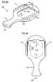
- FIG. 32is a top, front and end, exploded perspective view of the muscle compression apparatus of FIG. 31 ;
- FIG. 39is a top, front and end, exploded perspective view of the muscle compression apparatus of FIG. 37 ;
- the implant 10includes an elongated member 12 having a tissue in-growth end 14 and a static end 16 .
- the tissue in-growth end 14may be any tissue growth inducing material (e.g., felt or PET) to induce growth of tissue into the end 14 to secure the end 14 to surrounding tissue following implantation.
- the elongated member 12may be suture material one end secured to the felt 14 and with the static end 16 being a free end of the suture material 12 .
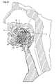
- the ablation member 104includes a housing 136 ( FIGS. 26-28 ) having a front end 138 and sidewalls 140 and bottom surface 144 .
- the housing 136is sized for the bottom surface 144 to slidably engage and abut the upper surface 114 of the tissue isolation member 102 .
- rails 142 on the sidewalls 140are received within the track 122 and with the guide member 121 abutting the sidewalls 140 .
- the front end 138opposes the opening 112 and the ablation member 140 is slidable on the upper surface in the direction of the incision path A.
- the rails 142 received within the tracks 122restrict the motion of the ablation member 104 to a back-and-forth motion in the direction of the incision path A.
- the housing 142contains a rotating shaft 146 for rotation about an axis Y-Y.
- a shaft 146terminates out the rear of the housing at a shaft coupling 147 contained with a male housing coupling 148 (shown as a bayonet-style attachment).
- Axis Y-Yis parallel with the incision path A and centrally positioned between the sidewalls 140 .
- the knife-edge 156slices into the tissue above the opening 112 with the resulting slice parallel to the upper surface 114 .
- the physiciancontinues advancement of the ablation member 104 in the direction of arrow A with the partially severed tissue flap F lifted by the ramp 139 .
- the ends 215 , 215 aare rounded to present a blunt surface. Further, the ends 215 , 215 a are radiused toward the inner surface 217 a and recessed beneath the inner surface 217 a by a depth D.
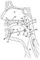
- a flapis formed in the tongue T near the base of the tongue using the tool 100 of FIG. 22 .
- the first brace 212is positioned beneath the flap with the upper surface 217 opposing the top of the tongue T and with the lower surface 217 a facing toward the chin of the patient.
- the spacing S of the braces 212 , 212 ′can be adjusted by the physician turning the head 234 of the shaft 236 thus adjusting the length of the connecting element 230 by further receiving the head 232 into the hub 218 . Accordingly, an amount of compression on the genioglossus muscle G (and geniohyoid muscle GM) can be adjusted by the surgeon. As little as 2 mm of compression may be adequate for a positive therapeutic effect. Compression of the genioglossus muscle with the aforementioned device 210 reshapes the tongue T and resists its collapse against the pharyngeal wall during sleep to maintain the airway patent during sleep. It will be appreciated that in the figures, the compression and re-shaping of the tongue T are shown exaggerated for ease of illustration.
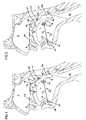
- An incision Iis formed beneath the chin of the patient and anterior to the hyoid HB to define a surgically created path from the incision to the hub 318 .
- the connecting member 330is passed through the incision path by aligning the axis of the rod 331 with the incision path and inserting the threaded end 332 into the incision path and moving the connecting element 330 until the threaded end 332 threadedly engages the hub 318 .
- an incisioncan be made through the skin of the chin and a sharp-tipped connecting member can be passed through to the hub 318 .
- the surgeoncan adjust the spacing between the flange 338 and the brace 312 by drawing and rotating the connecting element 330 to further insert the threaded end 332 within the hub 320 .
- the incisioncan then be closed.
- Such actiondraws the base of the tongue away from the pharyngeal wall and the roof of the mouth with the flange 338 opposing the geniohyoid muscle preventing migration of the connecting element into the tongue.
- the physiciancan re-adjust the spacing S at a later date if so desired.
Landscapes
- Health & Medical Sciences (AREA)
- Life Sciences & Earth Sciences (AREA)
- Surgery (AREA)
- Veterinary Medicine (AREA)
- Public Health (AREA)
- Biomedical Technology (AREA)
- Heart & Thoracic Surgery (AREA)
- Engineering & Computer Science (AREA)
- Animal Behavior & Ethology (AREA)
- General Health & Medical Sciences (AREA)
- Orthopedic Medicine & Surgery (AREA)
- Molecular Biology (AREA)
- Nuclear Medicine, Radiotherapy & Molecular Imaging (AREA)
- Medical Informatics (AREA)
- Oral & Maxillofacial Surgery (AREA)
- Otolaryngology (AREA)
- Pulmonology (AREA)
- Vascular Medicine (AREA)
- Dentistry (AREA)
- Cardiology (AREA)
- Transplantation (AREA)
- Neurology (AREA)
- Nursing (AREA)
- Surgical Instruments (AREA)
Abstract
Description
Claims (13)
Priority Applications (1)
| Application Number | Priority Date | Filing Date | Title |
|---|---|---|---|
| US11/107,160US7337781B2 (en) | 2005-04-15 | 2005-04-15 | Implant for tongue |
Applications Claiming Priority (1)
| Application Number | Priority Date | Filing Date | Title |
|---|---|---|---|
| US11/107,160US7337781B2 (en) | 2005-04-15 | 2005-04-15 | Implant for tongue |
Publications (2)
| Publication Number | Publication Date |
|---|---|
| US20060235264A1 US20060235264A1 (en) | 2006-10-19 |
| US7337781B2true US7337781B2 (en) | 2008-03-04 |
Family
ID=37109430
Family Applications (1)
| Application Number | Title | Priority Date | Filing Date |
|---|---|---|---|
| US11/107,160Active2025-11-11US7337781B2 (en) | 2005-04-15 | 2005-04-15 | Implant for tongue |
Country Status (1)
| Country | Link |
|---|---|
| US (1) | US7337781B2 (en) |
Cited By (63)
| Publication number | Priority date | Publication date | Assignee | Title |
|---|---|---|---|---|
| US20060150986A1 (en)* | 2004-12-15 | 2006-07-13 | Aspire Medical, Inc. | System and method for hyoidplasty |
| US20070261701A1 (en)* | 2004-02-26 | 2007-11-15 | Ira Sanders | Methods and Devices for Treating Sleep Apnea and Snoring |
| US20070295340A1 (en)* | 2006-06-23 | 2007-12-27 | Buscemi Paul J | Stiffening Procedure for Sleep Apnea |
| US20080188947A1 (en)* | 2004-02-26 | 2008-08-07 | Ira Sanders | Methods and devices for treating sleep apnea and snoring |
| US20080261886A1 (en)* | 2001-07-16 | 2008-10-23 | Novo Nordisk Healthcare A/G | Single-Dose Administration of Factor VIIa |
| WO2008156746A1 (en)* | 2007-06-18 | 2008-12-24 | Koninklijke Philips Electronics N.V. | Implantable devices, systems, and methods for maintaining desired orientations in targeted tissue regions |
| US20090014012A1 (en)* | 2004-02-26 | 2009-01-15 | Ira Sanders | Method And Device For The Treatment Of Obstructive Sleep Apnea And Snoring |
| US20090177027A1 (en)* | 2008-01-03 | 2009-07-09 | Gillis Edward M | Partially erodable systems for treatment of obstructive sleep apnea |
| US20100030011A1 (en)* | 2008-07-31 | 2010-02-04 | Ethicon, Inc. | Magnetic implants for treating obstructive sleep apnea and methods therefor |
| US20100024830A1 (en)* | 2008-07-30 | 2010-02-04 | Ethicon, Inc. | Methods and devices for forming an auxiliary airway for treating obstructive sleep apnea |
| US20100037901A1 (en)* | 2008-08-14 | 2010-02-18 | Rousseau Robert A | Methods and devices for treatment of obstructive sleep apnea |
| WO2010045546A1 (en)* | 2008-10-16 | 2010-04-22 | Linguaflex, Llc | Methods and devices for treating sleep apnea |
| US20100108077A1 (en)* | 2008-10-30 | 2010-05-06 | Ethicon, Inc. | Implant systems and methods for treating obstructive sleep apnea |
| US20100137905A1 (en)* | 2008-12-01 | 2010-06-03 | Weadock Kevin S | Implant systems and methods for treating obstructive sleep apnea |
| US20100132719A1 (en)* | 2008-12-01 | 2010-06-03 | Ethicon, Inc. | Implant systems and methods for treating obstructive sleep apnea |
| US20100163056A1 (en)* | 2008-12-30 | 2010-07-01 | Medartis Ag | Implant |
| US20100294284A1 (en)* | 2008-12-09 | 2010-11-25 | H-Medical | Apparatus, systems, and methods for constraining and/or supporting tissue structures along an airway |
| US20110100378A1 (en)* | 2009-10-30 | 2011-05-05 | Ethicon, Inc. | Flexible implants having internal volume shifting capabilities for treating obstructive sleep apnea |
| US7954494B1 (en) | 2008-03-26 | 2011-06-07 | Connor Robert A | Device with actively-moving members that hold or move the tongue |
| US20110144558A1 (en)* | 2009-12-15 | 2011-06-16 | Ethicon, Inc. | Fluid filled implants for treating medical conditions |
| US7975700B2 (en) | 2005-02-08 | 2011-07-12 | Koninklijke Philips Electronics N.V. | System for adjustable tissue anchors |
| US20110226262A1 (en)* | 2010-03-19 | 2011-09-22 | Gillis Edward M | Systems and methods for treatment of sleep apnea |
| US20110226263A1 (en)* | 2010-03-19 | 2011-09-22 | Gillis Edward M | Systems and methods for treatment of sleep apnea |
| US20110308530A1 (en)* | 2010-05-21 | 2011-12-22 | Gillis Edward M | Systems and methods for treatment of sleep apnea |
| US8096303B2 (en) | 2005-02-08 | 2012-01-17 | Koninklijke Philips Electronics N.V | Airway implants and methods and devices for insertion and retrieval |
| US20120017919A1 (en)* | 2010-07-26 | 2012-01-26 | Gillis Edward M | Systems and methods for treatment of sleep apnea |
| US20120132214A1 (en)* | 2010-11-30 | 2012-05-31 | Gillis Edward M | Systems and methods for treatment of sleep apnea |
| US20120138069A1 (en)* | 2010-12-03 | 2012-06-07 | Revent Medical, Inc. | Systems and methods for treatment of sleep apnea |
| US8307831B2 (en) | 2009-03-16 | 2012-11-13 | Ethicon, Inc. | Implant systems and methods for treating obstructive sleep apnea |
| US8327854B2 (en) | 2008-05-12 | 2012-12-11 | Revent Medical, Inc. | Partially erodable systems for treatment of obstructive sleep apnea |
| US8371307B2 (en) | 2005-02-08 | 2013-02-12 | Koninklijke Philips Electronics N.V. | Methods and devices for the treatment of airway obstruction, sleep apnea and snoring |
| CN103037820A (en)* | 2010-06-03 | 2013-04-10 | 皇家飞利浦电子股份有限公司 | Glossoplasty implant tension relief system |
| US8460322B2 (en) | 2010-03-31 | 2013-06-11 | Siesta Medical, Inc. | Suture passer systems and methods for tongue or other tissue suspension and compression |
| US8561616B2 (en) | 2008-10-24 | 2013-10-22 | Ethicon, Inc. | Methods and devices for the indirect displacement of the hyoid bone for treating obstructive sleep apnea |
| US20140007885A1 (en)* | 2012-07-06 | 2014-01-09 | Edward M. Gillis | Systems and methods for treatment of sleep apnea |
| US8813754B2 (en) | 2009-02-17 | 2014-08-26 | Ethicon, Inc. | Magnetic implants and methods for treating an oropharyngeal condition |
| US8905033B2 (en) | 2011-09-28 | 2014-12-09 | Ethicon, Inc. | Modular tissue securement systems |
| US8973582B2 (en) | 2011-11-30 | 2015-03-10 | Ethicon, Inc. | Tongue suspension device and method |
| US9161855B2 (en) | 2011-10-24 | 2015-10-20 | Ethicon, Inc. | Tissue supporting device and method |
| US9173766B2 (en) | 2012-06-01 | 2015-11-03 | Ethicon, Inc. | Systems and methods to treat upper pharyngeal airway of obstructive sleep apnea patients |
| US9326886B2 (en) | 2009-10-29 | 2016-05-03 | Ethicon, Inc. | Fluid filled implants for treating obstructive sleep apnea |
| US9439801B2 (en) | 2012-06-29 | 2016-09-13 | Revent Medical, Inc. | Systems and methods for treatment of sleep apnea |
| US9463014B2 (en) | 2012-09-07 | 2016-10-11 | Siesta Medical, Inc. | Tether line systems and methods for tongue or other tissue suspension or compression |
| US9480594B2 (en) | 2013-02-27 | 2016-11-01 | Spirox, Inc. | Nasal implants and systems and methods of use |
| US9597220B2 (en) | 2008-11-19 | 2017-03-21 | Spirox, Inc. | Apparatus and methods for correcting nasal valve collapse |
| US9867733B2 (en) | 2013-08-01 | 2018-01-16 | Cook Medical Technologies Llc | Tissue adjustment implant |
| US9877862B2 (en) | 2009-10-29 | 2018-01-30 | Ethicon, Inc. | Tongue suspension system with hyoid-extender for treating obstructive sleep apnea |
| US9913661B2 (en) | 2014-08-04 | 2018-03-13 | Cook Medical Technologies Llc | Medical devices having a releasable tubular member and methods of using the same |
| US9956384B2 (en) | 2014-01-24 | 2018-05-01 | Cook Medical Technologies Llc | Articulating balloon catheter and method for using the same |
| US9974563B2 (en) | 2014-05-28 | 2018-05-22 | Cook Medical Technologies Llc | Medical devices having a releasable member and methods of using the same |
| US10022263B2 (en) | 2011-07-14 | 2018-07-17 | Cook Medical Technologies Llc | Sling-based treatment of obstructive sleep apnea |
| US10123900B2 (en) | 2013-03-15 | 2018-11-13 | Cook Medical Technologies Llc | Devices, kits, and methods for the treatment of obstructive sleep apnea |
| US10166017B2 (en) | 2013-08-05 | 2019-01-01 | Cook Medical Technologies Llc | Medical devices having a releasable tubular member and methods of using the same |
| CN109688943A (en)* | 2016-06-10 | 2019-04-26 | 开普敦大学 | Implantable device |
| US10314736B2 (en) | 2012-10-16 | 2019-06-11 | Cook Medical Technologies Llc | Method and apparatus for treating obstructive sleep apnea (OSA) |
| US10398545B2 (en) | 2014-08-26 | 2019-09-03 | Spirox, Inc. | Nasal implants and systems and method of use |
| US10470760B2 (en) | 2011-12-08 | 2019-11-12 | Ethicon, Inc. | Modified tissue securement fibers |
| US10603163B2 (en) | 2006-09-25 | 2020-03-31 | Spirox, Inc. | Nasal implant introduced through a non-surgical injection technique |
| US10987133B2 (en) | 2016-05-02 | 2021-04-27 | Entellus Medical, Inc. | Nasal valve implants and methods of implanting the same |
| US10993800B2 (en) | 2015-09-25 | 2021-05-04 | Spirox, Inc. | Nasal implants and systems and method of use |
| US11039831B2 (en) | 2014-03-05 | 2021-06-22 | Siesta Medical, Inc. | Suture passer systems and methods for tongue or other tissue suspension and compression |
| US11357660B2 (en) | 2017-06-29 | 2022-06-14 | Cook Medical Technologies, LLC | Implantable medical devices for tissue repositioning |
| US12016583B2 (en) | 2016-12-13 | 2024-06-25 | Linguaflex, Inc. | Tongue retractor |
Families Citing this family (34)
| Publication number | Priority date | Publication date | Assignee | Title |
|---|---|---|---|---|
| US7992566B2 (en) | 2002-12-30 | 2011-08-09 | Quiescence Medical, Inc. | Apparatus and methods for treating sleep apnea |
| US9408742B2 (en) | 2005-02-08 | 2016-08-09 | Koninklijke Philips N.V. | Glossopexy adjustment system and method |
| US8220466B2 (en)* | 2005-02-08 | 2012-07-17 | Koninklijke Philips Electronics N.V. | System and method for percutaneous palate remodeling |
| US8186355B2 (en) | 2005-11-09 | 2012-05-29 | Koninklijke Philips Electronics N.V. | Glossoplasty using tissue anchor glossopexy with volumetric tongue reduction |
| US7909038B2 (en)* | 2006-04-20 | 2011-03-22 | Pavad Medical, Inc. | Tongue stabilization device and methods of using the same |
| EP2561842A1 (en)* | 2006-07-06 | 2013-02-27 | Quiescence Medical Inc | Apparatus for treating sleep apnea |
| US20080078411A1 (en)* | 2006-10-03 | 2008-04-03 | Restore Medical, Inc. | Tongue implant for sleep apnea |
| US20080078412A1 (en)* | 2006-10-03 | 2008-04-03 | Restore Medical, Inc. | Tongue implant |
| CA2781407A1 (en) | 2008-01-14 | 2009-07-23 | Michael P. Brenzel | Apparatus and methods for fracture repair |
| US20170216083A1 (en)* | 2008-05-12 | 2017-08-03 | Edward M. Gillis | Systems and methods for treatment of sleep apnea |
| US8555891B2 (en)* | 2009-02-18 | 2013-10-15 | Medtronic Xomed, Inc. | Implant system for controlling airway passage |
| US20110166598A1 (en) | 2009-12-02 | 2011-07-07 | Entrigue Surgical, Inc. | Devices and methods for tongue stabilization |
| US20110178520A1 (en) | 2010-01-15 | 2011-07-21 | Kyle Taylor | Rotary-rigid orthopaedic rod |
| WO2011091052A1 (en) | 2010-01-20 | 2011-07-28 | Kyle Taylor | Apparatus and methods for bone access and cavity preparation |
| WO2011112615A1 (en)* | 2010-03-08 | 2011-09-15 | Krinke Todd A | Apparatus and methods for securing a bone implant |
| EP2571463A4 (en)* | 2010-05-21 | 2014-08-13 | Revent Medical Inc | Systems and methods for treatment of sleep apnea |
| CN102198010B (en)* | 2010-09-29 | 2015-11-25 | 张湘民 | Embedded type tongue pulling device, towing plate, draught line, tractor and method |
| WO2012082791A2 (en) | 2010-12-13 | 2012-06-21 | Quiescence Medical, Inc. | Apparatus and methods for treating sleep apnea |
| US9078634B2 (en) | 2011-01-27 | 2015-07-14 | Cryosa, Llc | Apparatus and methods for treatment of obstructive sleep apnea utilizing cryolysis of adipose tissues |
| JP6484175B2 (en) | 2012-10-12 | 2019-03-13 | イーライ リリー アンド カンパニー | Chemical institutions and methods of their use, particularly in the injection of highly viscous fluids |
| US9321581B2 (en) | 2012-10-12 | 2016-04-26 | Eli Lilly And Company | Process and device for delivery of fluid by chemical reaction |
| US10531979B2 (en)* | 2013-03-15 | 2020-01-14 | Fabian Hermann Urban Füglister | Tongue deformation implant |
| CN105939677A (en) | 2013-12-12 | 2016-09-14 | 康文图斯整形外科公司 | Tissue displacement tools and methods |
| EP3151791A1 (en)* | 2014-06-09 | 2017-04-12 | Koninklijke Philips N.V. | A tongue treatment electrode and a device using the same |
| EP3200736B8 (en) | 2014-10-01 | 2020-06-17 | CryOSA, Inc. | Apparatus for treatment of obstructive sleep apnea utilizing cryolysis of adipose tissues |
| CN105982777B (en)* | 2015-02-09 | 2018-09-04 | 张湘民 | Implanted septum of tongue fascia pulling device and method for implantation |
| CN106963540A (en) | 2016-01-13 | 2017-07-21 | 周星 | Turbine and worm type tractor for embedded type tongue pulling device |
| WO2017121282A1 (en)* | 2016-01-13 | 2017-07-20 | 周星 | Worm wheel and worm screw traction apparatus for implanted tongue traction device |
| JP6841937B2 (en) | 2017-02-17 | 2021-03-10 | イーライ リリー アンド カンパニー | Processes and devices for the delivery of fluids by chemical reactions |
| WO2019010252A2 (en) | 2017-07-04 | 2019-01-10 | Conventus Orthopaedics, Inc. | APPARATUS AND METHODS FOR TREATING BONES |
| JP6971385B2 (en) | 2017-09-08 | 2021-11-24 | イーライ リリー アンド カンパニー | A system for controlling gas generation in drug delivery devices |
| EP3897779B1 (en) | 2018-12-19 | 2024-08-07 | Eli Lilly and Company | Devices and processes for delivery of therapeutic fluids |
| AU2019402055B2 (en) | 2018-12-19 | 2022-09-29 | Eli Lilly And Company | Devices for delivery of therapeutic fluids |
| JP2025502801A (en) | 2021-12-30 | 2025-01-28 | クライオサ, インク. | Systems and methods for treating obstructive sleep apnea - Patents.com |
Citations (16)
| Publication number | Priority date | Publication date | Assignee | Title |
|---|---|---|---|---|
| US5843021A (en) | 1994-05-09 | 1998-12-01 | Somnus Medical Technologies, Inc. | Cell necrosis apparatus |
| DE19756956C1 (en) | 1997-12-20 | 1999-07-15 | Wolfgang Dr Med Fege | Implant for implantation in a tongue |
| US5988171A (en) | 1997-06-26 | 1999-11-23 | Influence Medical Technologies, Ltd. | Methods and devices for the treatment of airway obstruction, sleep apnea and snoring |
| DE19920114A1 (en) | 1999-05-03 | 2000-11-09 | Fege Wolfgang | Throat side implant |
| US6161541A (en) | 1998-06-09 | 2000-12-19 | Influent Ltd. | Hyoid expansion and suspension procedure |
| US6250307B1 (en) | 1999-09-17 | 2001-06-26 | Pi Medical, Inc. | Snoring treatment |
| US6431174B1 (en) | 2000-08-10 | 2002-08-13 | Pi Medical, Inc. | Method and apparatus to treat conditions of the naso-pharyngeal area |
| US6513530B2 (en) | 1999-09-17 | 2003-02-04 | Pi Medical, Inc. | Braided palatal implant for snoring treatment |
| US6523542B2 (en) | 1999-09-17 | 2003-02-25 | Pi Medical, Inc. | Snoring treatment implant and method |
| US6601584B2 (en) | 1999-09-17 | 2003-08-05 | Pi Medical, Inc. | Contracting snoring treatment implant |
| US20040139975A1 (en) | 2002-09-06 | 2004-07-22 | Apneon, Inc. | Magnetic force devices, systems, and methods for resisting tissue collapse within the pharyngeal conduit |
| US20040149290A1 (en) | 2002-09-06 | 2004-08-05 | Apneon, Inc. | Devices, systems, and methods to fixate tissue within the regions of body, such as the pharyngeal conduit |
| US20050092332A1 (en) | 2003-10-31 | 2005-05-05 | Restore Medical, Inc. | Airway implant |
| US20050092334A1 (en) | 2003-10-31 | 2005-05-05 | Restore Medical, Inc. | Airway implant |
| WO2005082452A1 (en) | 2004-02-26 | 2005-09-09 | Ira Sanders | A method and device for the treatment of obstructive sleep apnea and snoring |
| WO2006072571A1 (en) | 2005-01-04 | 2006-07-13 | Klinikum Der Universität Regensburg | Implant device for the non-pneumatic adjustable positioning of a human or animal body part |
- 2005
- 2005-04-15USUS11/107,160patent/US7337781B2/enactiveActive
Patent Citations (17)
| Publication number | Priority date | Publication date | Assignee | Title |
|---|---|---|---|---|
| US5843021A (en) | 1994-05-09 | 1998-12-01 | Somnus Medical Technologies, Inc. | Cell necrosis apparatus |
| US5988171A (en) | 1997-06-26 | 1999-11-23 | Influence Medical Technologies, Ltd. | Methods and devices for the treatment of airway obstruction, sleep apnea and snoring |
| DE19756956C1 (en) | 1997-12-20 | 1999-07-15 | Wolfgang Dr Med Fege | Implant for implantation in a tongue |
| EP1039859B1 (en) | 1997-12-20 | 2003-12-03 | Wolfgang Fege | Implant for implantation in the tongue |
| US6161541A (en) | 1998-06-09 | 2000-12-19 | Influent Ltd. | Hyoid expansion and suspension procedure |
| DE19920114A1 (en) | 1999-05-03 | 2000-11-09 | Fege Wolfgang | Throat side implant |
| US6523542B2 (en) | 1999-09-17 | 2003-02-25 | Pi Medical, Inc. | Snoring treatment implant and method |
| US6513530B2 (en) | 1999-09-17 | 2003-02-04 | Pi Medical, Inc. | Braided palatal implant for snoring treatment |
| US6601584B2 (en) | 1999-09-17 | 2003-08-05 | Pi Medical, Inc. | Contracting snoring treatment implant |
| US6250307B1 (en) | 1999-09-17 | 2001-06-26 | Pi Medical, Inc. | Snoring treatment |
| US6431174B1 (en) | 2000-08-10 | 2002-08-13 | Pi Medical, Inc. | Method and apparatus to treat conditions of the naso-pharyngeal area |
| US20040139975A1 (en) | 2002-09-06 | 2004-07-22 | Apneon, Inc. | Magnetic force devices, systems, and methods for resisting tissue collapse within the pharyngeal conduit |
| US20040149290A1 (en) | 2002-09-06 | 2004-08-05 | Apneon, Inc. | Devices, systems, and methods to fixate tissue within the regions of body, such as the pharyngeal conduit |
| US20050092332A1 (en) | 2003-10-31 | 2005-05-05 | Restore Medical, Inc. | Airway implant |
| US20050092334A1 (en) | 2003-10-31 | 2005-05-05 | Restore Medical, Inc. | Airway implant |
| WO2005082452A1 (en) | 2004-02-26 | 2005-09-09 | Ira Sanders | A method and device for the treatment of obstructive sleep apnea and snoring |
| WO2006072571A1 (en) | 2005-01-04 | 2006-07-13 | Klinikum Der Universität Regensburg | Implant device for the non-pneumatic adjustable positioning of a human or animal body part |
Non-Patent Citations (7)
Cited By (127)
| Publication number | Priority date | Publication date | Assignee | Title |
|---|---|---|---|---|
| US20080261886A1 (en)* | 2001-07-16 | 2008-10-23 | Novo Nordisk Healthcare A/G | Single-Dose Administration of Factor VIIa |
| US9211210B2 (en) | 2003-12-15 | 2015-12-15 | Koninklijke Philips N.V. | System and method for hyoidplasty |
| US8408213B2 (en) | 2004-02-26 | 2013-04-02 | Linguaflex, Inc. | Method and device for the treatment of obstructive sleep apnea and snoring |
| US8220467B2 (en) | 2004-02-26 | 2012-07-17 | Linguaflex, Inc. | Method and device for the treatment of obstructive sleep apnea and snoring |
| US20070261701A1 (en)* | 2004-02-26 | 2007-11-15 | Ira Sanders | Methods and Devices for Treating Sleep Apnea and Snoring |
| US8074655B2 (en) | 2004-02-26 | 2011-12-13 | Linguaflex, Inc. | Methods and devices for treating sleep apnea and snoring |
| US20090014012A1 (en)* | 2004-02-26 | 2009-01-15 | Ira Sanders | Method And Device For The Treatment Of Obstructive Sleep Apnea And Snoring |
| US11666476B2 (en) | 2004-02-26 | 2023-06-06 | Linguaflex, Inc. | Method and device for the treatment of obstructive sleep apnea and snoring |
| US10195010B2 (en) | 2004-02-26 | 2019-02-05 | Linguaflex, Inc. | Methods and devices for treating sleep apnea and snoring |
| US8925551B2 (en) | 2004-02-26 | 2015-01-06 | Linguaflex, Inc. | Method and device for the treatment of obstructive sleep apnea and snoring |
| US20080188947A1 (en)* | 2004-02-26 | 2008-08-07 | Ira Sanders | Methods and devices for treating sleep apnea and snoring |
| US10524954B2 (en) | 2004-02-26 | 2020-01-07 | Linguaflex, Inc. | Methods and devices for treating sleep apnea and snoring |
| US20060150986A1 (en)* | 2004-12-15 | 2006-07-13 | Aspire Medical, Inc. | System and method for hyoidplasty |
| US8777958B2 (en)* | 2004-12-15 | 2014-07-15 | Koninklijke Philips N.V. | System and method for hyoidplasty |
| US8080014B2 (en)* | 2004-12-15 | 2011-12-20 | Koninklijke Philips Electronics N.V. | System and method for hyoidplasty |
| US20120296340A1 (en)* | 2004-12-15 | 2012-11-22 | Roue Chad C | System and method for hyoidplasty |
| US7992567B2 (en) | 2005-02-08 | 2011-08-09 | Koninklijke Philips Electronics N.V. | System and method for percutaneous glossoplasty |
| US8371307B2 (en) | 2005-02-08 | 2013-02-12 | Koninklijke Philips Electronics N.V. | Methods and devices for the treatment of airway obstruction, sleep apnea and snoring |
| US8096303B2 (en) | 2005-02-08 | 2012-01-17 | Koninklijke Philips Electronics N.V | Airway implants and methods and devices for insertion and retrieval |
| US8757163B2 (en) | 2005-02-08 | 2014-06-24 | Koninklijke Philips N.V. | Airway implants and methods and devices for insertion and retrieval |
| US7975700B2 (en) | 2005-02-08 | 2011-07-12 | Koninklijke Philips Electronics N.V. | System for adjustable tissue anchors |
| US8517028B2 (en) | 2006-06-23 | 2013-08-27 | Medtronic Xomed, Inc. | Stiffening procedure for sleep apnea |
| US20070295340A1 (en)* | 2006-06-23 | 2007-12-27 | Buscemi Paul J | Stiffening Procedure for Sleep Apnea |
| US10603163B2 (en) | 2006-09-25 | 2020-03-31 | Spirox, Inc. | Nasal implant introduced through a non-surgical injection technique |
| US12133794B2 (en) | 2006-09-25 | 2024-11-05 | Stryker Corporation | Nasal implant introduced through a non-surgical injection technique |
| WO2008156746A1 (en)* | 2007-06-18 | 2008-12-24 | Koninklijke Philips Electronics N.V. | Implantable devices, systems, and methods for maintaining desired orientations in targeted tissue regions |
| US8167787B2 (en) | 2008-01-03 | 2012-05-01 | Revent Medical, Inc. | Partially erodable systems for treatment of obstructive sleep apnea |
| US8523760B2 (en) | 2008-01-03 | 2013-09-03 | Revent Medical, Inc. | Partially erodable systems for treatment of obstructive sleep apnea |
| US8747296B2 (en) | 2008-01-03 | 2014-06-10 | Revent Medical, Inc. | Partially erodable systems for treatment of obstructive sleep apnea |
| US20090177027A1 (en)* | 2008-01-03 | 2009-07-09 | Gillis Edward M | Partially erodable systems for treatment of obstructive sleep apnea |
| US7954494B1 (en) | 2008-03-26 | 2011-06-07 | Connor Robert A | Device with actively-moving members that hold or move the tongue |
| US8327854B2 (en) | 2008-05-12 | 2012-12-11 | Revent Medical, Inc. | Partially erodable systems for treatment of obstructive sleep apnea |
| US8991398B2 (en) | 2008-05-12 | 2015-03-31 | Revent Medical, Inc. | Partially erodable systems for treatment of obstructive sleep apnea |
| US8707960B2 (en) | 2008-05-12 | 2014-04-29 | Revent Medical, Inc. | Partially erodable systems for treatment of obstructive sleep apnea |
| US20100024830A1 (en)* | 2008-07-30 | 2010-02-04 | Ethicon, Inc. | Methods and devices for forming an auxiliary airway for treating obstructive sleep apnea |
| US8678008B2 (en) | 2008-07-30 | 2014-03-25 | Ethicon, Inc | Methods and devices for forming an auxiliary airway for treating obstructive sleep apnea |
| US8556797B2 (en) | 2008-07-31 | 2013-10-15 | Ethicon, Inc. | Magnetic implants for treating obstructive sleep apnea and methods therefor |
| US20100030011A1 (en)* | 2008-07-31 | 2010-02-04 | Ethicon, Inc. | Magnetic implants for treating obstructive sleep apnea and methods therefor |
| US9144511B2 (en) | 2008-08-14 | 2015-09-29 | Ethicon, Inc. | Methods and devices for treatment of obstructive sleep apnea |
| US20100037901A1 (en)* | 2008-08-14 | 2010-02-18 | Rousseau Robert A | Methods and devices for treatment of obstructive sleep apnea |
| US8413661B2 (en) | 2008-08-14 | 2013-04-09 | Ethicon, Inc. | Methods and devices for treatment of obstructive sleep apnea |
| US10736771B2 (en) | 2008-10-16 | 2020-08-11 | Linguaflex, Inc. | Methods and devices for treating sleep apnea |
| WO2010045546A1 (en)* | 2008-10-16 | 2010-04-22 | Linguaflex, Llc | Methods and devices for treating sleep apnea |
| CN102215793A (en)* | 2008-10-16 | 2011-10-12 | 舌伸缩有限公司 | Methods and devices for treating sleep apnea |
| US9925086B2 (en) | 2008-10-16 | 2018-03-27 | Linguaflex, Inc. | Methods and devices for treating sleep apnea |
| US20110230727A1 (en)* | 2008-10-16 | 2011-09-22 | Linguaflex , Inc. | Methods and Devices for Treating Sleep Apnea |
| US11717436B2 (en) | 2008-10-16 | 2023-08-08 | Linguaflex, Inc. | Methods and devices for treating sleep apnea |
| US8561616B2 (en) | 2008-10-24 | 2013-10-22 | Ethicon, Inc. | Methods and devices for the indirect displacement of the hyoid bone for treating obstructive sleep apnea |
| US8561617B2 (en) | 2008-10-30 | 2013-10-22 | Ethicon, Inc. | Implant systems and methods for treating obstructive sleep apnea |
| US20100108077A1 (en)* | 2008-10-30 | 2010-05-06 | Ethicon, Inc. | Implant systems and methods for treating obstructive sleep apnea |
| US9597220B2 (en) | 2008-11-19 | 2017-03-21 | Spirox, Inc. | Apparatus and methods for correcting nasal valve collapse |
| US11806265B2 (en) | 2008-11-19 | 2023-11-07 | Spirox, Inc. | Apparatus and methods for correcting nasal valve collapse |
| US10786383B2 (en) | 2008-11-19 | 2020-09-29 | Spirox, Inc. | Apparatus and methods for correcting nasal valve collapse |
| US20100137905A1 (en)* | 2008-12-01 | 2010-06-03 | Weadock Kevin S | Implant systems and methods for treating obstructive sleep apnea |
| US8915252B2 (en) | 2008-12-01 | 2014-12-23 | Ethicon, Inc. | Implant systems and methods for treating obstructive sleep apnea |
| US20100132719A1 (en)* | 2008-12-01 | 2010-06-03 | Ethicon, Inc. | Implant systems and methods for treating obstructive sleep apnea |
| US8800567B2 (en) | 2008-12-01 | 2014-08-12 | Ethicon, Inc. | Implant systems and methods for treating obstructive sleep apnea |
| US8783258B2 (en) | 2008-12-01 | 2014-07-22 | Ethicon, Inc. | Implant systems and methods for treating obstructive sleep apnea |
| US8695607B2 (en) | 2008-12-09 | 2014-04-15 | Sileomed, Inc. | Apparatus, systems, and methods for constraining and/or supporting tissue structures along an airway |
| US20100294284A1 (en)* | 2008-12-09 | 2010-11-25 | H-Medical | Apparatus, systems, and methods for constraining and/or supporting tissue structures along an airway |
| US20100163056A1 (en)* | 2008-12-30 | 2010-07-01 | Medartis Ag | Implant |
| US10441456B2 (en) | 2008-12-30 | 2019-10-15 | Medartis Ag | Implant |
| US8813754B2 (en) | 2009-02-17 | 2014-08-26 | Ethicon, Inc. | Magnetic implants and methods for treating an oropharyngeal condition |
| US8307831B2 (en) | 2009-03-16 | 2012-11-13 | Ethicon, Inc. | Implant systems and methods for treating obstructive sleep apnea |
| US9877862B2 (en) | 2009-10-29 | 2018-01-30 | Ethicon, Inc. | Tongue suspension system with hyoid-extender for treating obstructive sleep apnea |
| US9326886B2 (en) | 2009-10-29 | 2016-05-03 | Ethicon, Inc. | Fluid filled implants for treating obstructive sleep apnea |
| US20110100378A1 (en)* | 2009-10-30 | 2011-05-05 | Ethicon, Inc. | Flexible implants having internal volume shifting capabilities for treating obstructive sleep apnea |
| US9974683B2 (en) | 2009-10-30 | 2018-05-22 | Ethicon, Inc. | Flexible implants having internal volume shifting capabilities for treating obstructive sleep apnea |
| US8632488B2 (en) | 2009-12-15 | 2014-01-21 | Ethicon, Inc. | Fluid filled implants for treating medical conditions |
| US20110144558A1 (en)* | 2009-12-15 | 2011-06-16 | Ethicon, Inc. | Fluid filled implants for treating medical conditions |
| US20110226262A1 (en)* | 2010-03-19 | 2011-09-22 | Gillis Edward M | Systems and methods for treatment of sleep apnea |
| US20110226263A1 (en)* | 2010-03-19 | 2011-09-22 | Gillis Edward M | Systems and methods for treatment of sleep apnea |
| US9381109B2 (en) | 2010-03-19 | 2016-07-05 | Revent Medical, Inc. | Systems and methods for treatment of sleep apnea |
| US8776799B2 (en)* | 2010-03-19 | 2014-07-15 | Revent Medical, Inc. | Systems and methods for treatment of sleep apnea |
| US8733363B2 (en) | 2010-03-19 | 2014-05-27 | Revent Medical, Inc. | Systems and methods for treatment of sleep apnea |
| US10182810B2 (en) | 2010-03-31 | 2019-01-22 | Siesta Medical, Inc. | Methods for hyoid suspension |
| US9386981B2 (en) | 2010-03-31 | 2016-07-12 | Siesta Medical, Inc. | Suture passer systems and methods for palate suspension and compression |
| US8460322B2 (en) | 2010-03-31 | 2013-06-11 | Siesta Medical, Inc. | Suture passer systems and methods for tongue or other tissue suspension and compression |
| US12201291B2 (en) | 2010-03-31 | 2025-01-21 | Siesta Medical, Inc. | Suture passer systems and methods for tongue or other tissue suspension and compression |
| US10966710B2 (en) | 2010-03-31 | 2021-04-06 | Siesta Medical, Inc. | Suture passer systems and methods for tongue or other tissue suspension and compression |
| US11672528B2 (en) | 2010-03-31 | 2023-06-13 | Siesta Medical, Inc. | Suture passer systems and methods for tongue or other tissue suspension and compression |
| US9510922B2 (en)* | 2010-05-21 | 2016-12-06 | Revent Medical, Inc. | Systems and methods for treatment of sleep apnea |
| US20110308530A1 (en)* | 2010-05-21 | 2011-12-22 | Gillis Edward M | Systems and methods for treatment of sleep apnea |
| US9833353B2 (en) | 2010-06-03 | 2017-12-05 | Koninklijke Philips N.V. | Glossoplasty implant tension relief system |
| CN103037820A (en)* | 2010-06-03 | 2013-04-10 | 皇家飞利浦电子股份有限公司 | Glossoplasty implant tension relief system |
| CN103037820B (en)* | 2010-06-03 | 2015-02-25 | 皇家飞利浦电子股份有限公司 | Glossoplasty implant tension relief system |
| US9707122B2 (en)* | 2010-07-26 | 2017-07-18 | Revent Medical, Inc. | Systems and methods for treatment of sleep apnea |
| US20120017919A1 (en)* | 2010-07-26 | 2012-01-26 | Gillis Edward M | Systems and methods for treatment of sleep apnea |
| US20120132214A1 (en)* | 2010-11-30 | 2012-05-31 | Gillis Edward M | Systems and methods for treatment of sleep apnea |
| US20120138069A1 (en)* | 2010-12-03 | 2012-06-07 | Revent Medical, Inc. | Systems and methods for treatment of sleep apnea |
| US10022263B2 (en) | 2011-07-14 | 2018-07-17 | Cook Medical Technologies Llc | Sling-based treatment of obstructive sleep apnea |
| US8905033B2 (en) | 2011-09-28 | 2014-12-09 | Ethicon, Inc. | Modular tissue securement systems |
| US9592046B2 (en) | 2011-09-28 | 2017-03-14 | Ethicon, Inc. | Modular tissue securement systems |
| US9161855B2 (en) | 2011-10-24 | 2015-10-20 | Ethicon, Inc. | Tissue supporting device and method |
| US8973582B2 (en) | 2011-11-30 | 2015-03-10 | Ethicon, Inc. | Tongue suspension device and method |
| US10470760B2 (en) | 2011-12-08 | 2019-11-12 | Ethicon, Inc. | Modified tissue securement fibers |
| US9173766B2 (en) | 2012-06-01 | 2015-11-03 | Ethicon, Inc. | Systems and methods to treat upper pharyngeal airway of obstructive sleep apnea patients |
| US9439801B2 (en) | 2012-06-29 | 2016-09-13 | Revent Medical, Inc. | Systems and methods for treatment of sleep apnea |
| US20140007885A1 (en)* | 2012-07-06 | 2014-01-09 | Edward M. Gillis | Systems and methods for treatment of sleep apnea |
| US11064991B2 (en)* | 2012-09-07 | 2021-07-20 | Siesta Medical, Inc. | Tether line systems and methods for tongue or other tissue suspension or compression |
| US9463014B2 (en) | 2012-09-07 | 2016-10-11 | Siesta Medical, Inc. | Tether line systems and methods for tongue or other tissue suspension or compression |
| US10314736B2 (en) | 2012-10-16 | 2019-06-11 | Cook Medical Technologies Llc | Method and apparatus for treating obstructive sleep apnea (OSA) |
| US10588740B2 (en) | 2013-02-27 | 2020-03-17 | Spirox, Inc . | Nasal implants and systems and methods of use |
| US9480594B2 (en) | 2013-02-27 | 2016-11-01 | Spirox, Inc. | Nasal implants and systems and methods of use |
| US11890186B2 (en) | 2013-02-27 | 2024-02-06 | Spirox, Inc. | Nasal implants and systems and methods of use |
| US10123900B2 (en) | 2013-03-15 | 2018-11-13 | Cook Medical Technologies Llc | Devices, kits, and methods for the treatment of obstructive sleep apnea |
| US10799388B2 (en) | 2013-08-01 | 2020-10-13 | Cook Medical Technologies Llc | Tissue adjustment implant |
| US9867733B2 (en) | 2013-08-01 | 2018-01-16 | Cook Medical Technologies Llc | Tissue adjustment implant |
| US11744726B2 (en) | 2013-08-01 | 2023-09-05 | Cook Medical Technologies Llc | Tissue adjustment implant |
| US10166017B2 (en) | 2013-08-05 | 2019-01-01 | Cook Medical Technologies Llc | Medical devices having a releasable tubular member and methods of using the same |
| US9956384B2 (en) | 2014-01-24 | 2018-05-01 | Cook Medical Technologies Llc | Articulating balloon catheter and method for using the same |
| US11039831B2 (en) | 2014-03-05 | 2021-06-22 | Siesta Medical, Inc. | Suture passer systems and methods for tongue or other tissue suspension and compression |
| US11974738B2 (en) | 2014-03-05 | 2024-05-07 | Siesta Medical, Inc. | Systems and methods for tissue suspension and compression |
| US11642123B2 (en) | 2014-03-05 | 2023-05-09 | Siesta Medical, Inc. | Systems and methods for tissue suspension and compression |
| US10898224B2 (en) | 2014-05-28 | 2021-01-26 | Cook Medical Technologies Llc | Medical devices having a releasable member and methods of using the same |
| US9974563B2 (en) | 2014-05-28 | 2018-05-22 | Cook Medical Technologies Llc | Medical devices having a releasable member and methods of using the same |
| US9913661B2 (en) | 2014-08-04 | 2018-03-13 | Cook Medical Technologies Llc | Medical devices having a releasable tubular member and methods of using the same |
| US10980631B2 (en) | 2014-08-26 | 2021-04-20 | Spirox, Inc. | Nasal implants and systems and method of use |
| US10398545B2 (en) | 2014-08-26 | 2019-09-03 | Spirox, Inc. | Nasal implants and systems and method of use |
| US12213877B2 (en) | 2014-08-26 | 2025-02-04 | Stryker Corporation | Nasal implants and systems and method of use |
| US11737865B2 (en) | 2015-09-25 | 2023-08-29 | Spirox, Inc. | Nasal implants and systems and method of use |
| US10993800B2 (en) | 2015-09-25 | 2021-05-04 | Spirox, Inc. | Nasal implants and systems and method of use |
| US10987133B2 (en) | 2016-05-02 | 2021-04-27 | Entellus Medical, Inc. | Nasal valve implants and methods of implanting the same |
| US11931071B2 (en) | 2016-05-02 | 2024-03-19 | Entellus Medical, Inc. | Nasal valve implants and methods of implanting the same |
| CN109688943A (en)* | 2016-06-10 | 2019-04-26 | 开普敦大学 | Implantable device |
| US12016583B2 (en) | 2016-12-13 | 2024-06-25 | Linguaflex, Inc. | Tongue retractor |
| US11357660B2 (en) | 2017-06-29 | 2022-06-14 | Cook Medical Technologies, LLC | Implantable medical devices for tissue repositioning |
Also Published As
| Publication number | Publication date |
|---|---|
| US20060235264A1 (en) | 2006-10-19 |
Similar Documents
| Publication | Publication Date | Title |
|---|---|---|
| US7337781B2 (en) | Implant for tongue | |
| US7401611B2 (en) | Airway implant | |
| EP1691738B1 (en) | Airway implant | |
| US20060235380A1 (en) | Tissue incision tool | |
| US7845357B2 (en) | Tongue implant for sleep apnea | |
| US8381735B2 (en) | Tongue implant | |
| US9211210B2 (en) | System and method for hyoidplasty | |
| US6899105B2 (en) | Airway implant cartridge and kit | |
| US8517028B2 (en) | Stiffening procedure for sleep apnea | |
| US8821495B2 (en) | System and method for hyoidplasty | |
| KR101562839B1 (en) | Methods and devices for forming an auxiliary airway for treating obstructive sleep apnea | |
| US9510922B2 (en) | Systems and methods for treatment of sleep apnea | |
| US9173766B2 (en) | Systems and methods to treat upper pharyngeal airway of obstructive sleep apnea patients | |
| US9707122B2 (en) | Systems and methods for treatment of sleep apnea | |
| WO2015134763A1 (en) | Systems and methods for tissue suspension and compression | |
| CN110709022B (en) | Acromioclavicular hook plate | |
| US20120138069A1 (en) | Systems and methods for treatment of sleep apnea | |
| US20050065615A1 (en) | Airway implant and delivery tool and kit | |
| US20140007885A1 (en) | Systems and methods for treatment of sleep apnea | |
| JP2023531597A (en) | Systems and methods for reshaping nasal tissue | |
| Volpi | Yosef P. Krespi, MD, FACS David O. Volpi, MD, PC, FACS Alexander K. Arrow, MD, CFA Stephanie Culver, MD | |
| Terris et al. | Salvage of failed palate |
Legal Events
| Date | Code | Title | Description |
|---|---|---|---|
| AS | Assignment | Owner name:RESTORE MEDICAL, INC., MINNESOTA Free format text:ASSIGNMENT OF ASSIGNORS INTEREST;ASSIGNOR:VASSALLO, CHARLES;REEL/FRAME:016485/0184 Effective date:20050412 | |
| STCF | Information on status: patent grant | Free format text:PATENTED CASE | |
| AS | Assignment | Owner name:MEDTRONIC RESTORE MEDICAL, INC., FLORIDA Free format text:MERGER;ASSIGNOR:RESTORE MEDICAL, INC.;REEL/FRAME:023427/0092 Effective date:20080716 Owner name:MEDTRONIC RESTORE MEDICAL, INC.,FLORIDA Free format text:MERGER;ASSIGNOR:RESTORE MEDICAL, INC.;REEL/FRAME:023427/0092 Effective date:20080716 | |
| AS | Assignment | Owner name:MEDTRONIC XOMED, INC., FLORIDA Free format text:MERGER;ASSIGNOR:MEDTRONIC RESTORE MEDICAL, INC.;REEL/FRAME:023427/0840 Effective date:20090424 Owner name:MEDTRONIC XOMED, INC.,FLORIDA Free format text:MERGER;ASSIGNOR:MEDTRONIC RESTORE MEDICAL, INC.;REEL/FRAME:023427/0840 Effective date:20090424 | |
| FEPP | Fee payment procedure | Free format text:PAT HOLDER NO LONGER CLAIMS SMALL ENTITY STATUS, ENTITY STATUS SET TO UNDISCOUNTED (ORIGINAL EVENT CODE: STOL); ENTITY STATUS OF PATENT OWNER: LARGE ENTITY | |
| REFU | Refund | Free format text:REFUND - SURCHARGE, PETITION TO ACCEPT PYMT AFTER EXP, UNINTENTIONAL (ORIGINAL EVENT CODE: R2551); ENTITY STATUS OF PATENT OWNER: LARGE ENTITY | |
| FPAY | Fee payment | Year of fee payment:4 | |
| FPAY | Fee payment | Year of fee payment:4 | |
| SULP | Surcharge for late payment | ||
| FPAY | Fee payment | Year of fee payment:8 | |
| MAFP | Maintenance fee payment | Free format text:PAYMENT OF MAINTENANCE FEE, 12TH YEAR, LARGE ENTITY (ORIGINAL EVENT CODE: M1553); ENTITY STATUS OF PATENT OWNER: LARGE ENTITY Year of fee payment:12 |