US7337674B2 - Pressure detector for fluid circuits - Google Patents
Pressure detector for fluid circuitsDownload PDFInfo
- Publication number
- US7337674B2 US7337674B2US11/160,586US16058605AUS7337674B2US 7337674 B2US7337674 B2US 7337674B2US 16058605 AUS16058605 AUS 16058605AUS 7337674 B2US7337674 B2US 7337674B2
- Authority
- US
- United States
- Prior art keywords
- pressure
- tube
- sensor
- sensor portion
- vessel
- Prior art date
- Legal status (The legal status is an assumption and is not a legal conclusion. Google has not performed a legal analysis and makes no representation as to the accuracy of the status listed.)
- Active, expires
Links
- 239000012530fluidSubstances0.000titleclaimsabstractdescription35
- 230000008859changeEffects0.000claimsabstractdescription11
- 238000009530blood pressure measurementMethods0.000claimsabstractdescription7
- 238000006073displacement reactionMethods0.000claimsdescription13
- 230000007246mechanismEffects0.000claimsdescription13
- 230000036316preloadEffects0.000claimsdescription5
- 238000012959renal replacement therapyMethods0.000claims1
- 239000008280bloodSubstances0.000abstractdescription18
- 210000004369bloodAnatomy0.000abstractdescription18
- 239000000463materialSubstances0.000abstractdescription14
- 239000002699waste materialSubstances0.000abstractdescription9
- 230000008901benefitEffects0.000abstractdescription3
- 238000012544monitoring processMethods0.000abstract1
- 238000005259measurementMethods0.000description9
- 230000000694effectsEffects0.000description7
- 238000000034methodMethods0.000description7
- 229920003023plasticPolymers0.000description6
- 239000004033plasticSubstances0.000description6
- 230000004044responseEffects0.000description5
- 238000004891communicationMethods0.000description4
- 238000000108ultra-filtrationMethods0.000description4
- 238000013461designMethods0.000description3
- 239000013060biological fluidSubstances0.000description2
- 230000036770blood supplyEffects0.000description2
- XSQUKJJJFZCRTK-UHFFFAOYSA-NUreaChemical compoundNC(N)=OXSQUKJJJFZCRTK-UHFFFAOYSA-N0.000description1
- 230000004308accommodationEffects0.000description1
- 239000002253acidSubstances0.000description1
- 230000004075alterationEffects0.000description1
- 238000005452bendingMethods0.000description1
- 230000017531blood circulationEffects0.000description1
- 230000036772blood pressureEffects0.000description1
- 238000011088calibration curveMethods0.000description1
- 239000004202carbamideSubstances0.000description1
- 230000002596correlated effectEffects0.000description1
- 230000000875corresponding effectEffects0.000description1
- 230000008878couplingEffects0.000description1
- 238000010168coupling processMethods0.000description1
- 238000005859coupling reactionMethods0.000description1
- 238000010586diagramMethods0.000description1
- 238000010438heat treatmentMethods0.000description1
- 238000010348incorporationMethods0.000description1
- 210000003127kneeAnatomy0.000description1
- 239000007788liquidSubstances0.000description1
- 239000012528membraneSubstances0.000description1
- 239000002184metalSubstances0.000description1
- 230000003287optical effectEffects0.000description1
- 229920000642polymerPolymers0.000description1
- 230000008569processEffects0.000description1
- 238000012545processingMethods0.000description1
- 230000009257reactivityEffects0.000description1
- 230000035945sensitivityEffects0.000description1
- 238000007619statistical methodMethods0.000description1
- 239000000126substanceSubstances0.000description1
- 238000002560therapeutic procedureMethods0.000description1
- 239000003053toxinSubstances0.000description1
- 231100000765toxinToxicity0.000description1
- 108700012359toxinsProteins0.000description1
- 239000002441uremic toxinSubstances0.000description1
Images


Classifications
- G—PHYSICS
- G01—MEASURING; TESTING
- G01L—MEASURING FORCE, STRESS, TORQUE, WORK, MECHANICAL POWER, MECHANICAL EFFICIENCY, OR FLUID PRESSURE
- G01L7/00—Measuring the steady or quasi-steady pressure of a fluid or a fluent solid material by mechanical or fluid pressure-sensitive elements
- G01L7/02—Measuring the steady or quasi-steady pressure of a fluid or a fluent solid material by mechanical or fluid pressure-sensitive elements in the form of elastically-deformable gauges
- G01L7/024—Measuring the steady or quasi-steady pressure of a fluid or a fluent solid material by mechanical or fluid pressure-sensitive elements in the form of elastically-deformable gauges with mechanical transmitting or indicating means
- A—HUMAN NECESSITIES
- A61—MEDICAL OR VETERINARY SCIENCE; HYGIENE
- A61M—DEVICES FOR INTRODUCING MEDIA INTO, OR ONTO, THE BODY; DEVICES FOR TRANSDUCING BODY MEDIA OR FOR TAKING MEDIA FROM THE BODY; DEVICES FOR PRODUCING OR ENDING SLEEP OR STUPOR
- A61M1/00—Suction or pumping devices for medical purposes; Devices for carrying-off, for treatment of, or for carrying-over, body-liquids; Drainage systems
- A61M1/36—Other treatment of blood in a by-pass of the natural circulatory system, e.g. temperature adaptation, irradiation ; Extra-corporeal blood circuits
- A61M1/3621—Extra-corporeal blood circuits
- A61M1/3622—Extra-corporeal blood circuits with a cassette forming partially or totally the blood circuit
- A61M1/36222—Details related to the interface between cassette and machine
- A—HUMAN NECESSITIES
- A61—MEDICAL OR VETERINARY SCIENCE; HYGIENE
- A61M—DEVICES FOR INTRODUCING MEDIA INTO, OR ONTO, THE BODY; DEVICES FOR TRANSDUCING BODY MEDIA OR FOR TAKING MEDIA FROM THE BODY; DEVICES FOR PRODUCING OR ENDING SLEEP OR STUPOR
- A61M1/00—Suction or pumping devices for medical purposes; Devices for carrying-off, for treatment of, or for carrying-over, body-liquids; Drainage systems
- A61M1/36—Other treatment of blood in a by-pass of the natural circulatory system, e.g. temperature adaptation, irradiation ; Extra-corporeal blood circuits
- A61M1/3621—Extra-corporeal blood circuits
- A61M1/3622—Extra-corporeal blood circuits with a cassette forming partially or totally the blood circuit
- A61M1/36224—Extra-corporeal blood circuits with a cassette forming partially or totally the blood circuit with sensing means or components thereof
- A—HUMAN NECESSITIES
- A61—MEDICAL OR VETERINARY SCIENCE; HYGIENE
- A61M—DEVICES FOR INTRODUCING MEDIA INTO, OR ONTO, THE BODY; DEVICES FOR TRANSDUCING BODY MEDIA OR FOR TAKING MEDIA FROM THE BODY; DEVICES FOR PRODUCING OR ENDING SLEEP OR STUPOR
- A61M1/00—Suction or pumping devices for medical purposes; Devices for carrying-off, for treatment of, or for carrying-over, body-liquids; Drainage systems
- A61M1/36—Other treatment of blood in a by-pass of the natural circulatory system, e.g. temperature adaptation, irradiation ; Extra-corporeal blood circuits
- A61M1/3621—Extra-corporeal blood circuits
- A61M1/3639—Blood pressure control, pressure transducers specially adapted therefor
- A—HUMAN NECESSITIES
- A61—MEDICAL OR VETERINARY SCIENCE; HYGIENE
- A61M—DEVICES FOR INTRODUCING MEDIA INTO, OR ONTO, THE BODY; DEVICES FOR TRANSDUCING BODY MEDIA OR FOR TAKING MEDIA FROM THE BODY; DEVICES FOR PRODUCING OR ENDING SLEEP OR STUPOR
- A61M1/00—Suction or pumping devices for medical purposes; Devices for carrying-off, for treatment of, or for carrying-over, body-liquids; Drainage systems
- A61M1/36—Other treatment of blood in a by-pass of the natural circulatory system, e.g. temperature adaptation, irradiation ; Extra-corporeal blood circuits
- A61M1/3621—Extra-corporeal blood circuits
- A61M1/3622—Extra-corporeal blood circuits with a cassette forming partially or totally the blood circuit
- A61M1/36222—Details related to the interface between cassette and machine
- A61M1/362227—Details related to the interface between cassette and machine the interface providing means for actuating on functional elements of the cassette, e.g. plungers
Definitions
- Pressure transducersare used widely for pressure measurement.
- An example prior art deviceis described in U.S. Pat. No. 4,576,181 and illustrated in FIG. 1A .
- Such devicesrequire connection to a flow channel or chamber to provide fluid communication with a sensor portion.
- a flow channel 32 of a prior art deviceprovides fluid communication between a diaphragm 45 and a vessel or conduit 30 containing a fluid whose pressure is to be measured, from some flow or containment system 47 .
- An intermediate fluid in a space 35 on an opposite side of the diaphragm 45communicates with a pressure transducer 40 .
- the fluid whose pressure is to be measuredexerts a pressure on the diaphragm 45 in turn exerting a pressure on the intermediate fluid in space 35 .
- a pressure transducer 40generates a signal corresponding to the pressure of the intermediate fluid in the space 35 by any of various mechanisms, typically involving a strain gage or load cell.
- FIG. 1BAnother known device for measuring pressure is illustrated in FIG. 1B .
- a thin plate 30has a strain gage 10 on a back surface 31 thereof.
- a pliant thin-walled vessel 20rests against a front surface 32 of the thin plate 30 .
- fluid 25 inside the vessel 20pressurizes the vessel, which is bounded by walls 15 and 22 , thin plate 30 flexes, stretching a strain gauge 10 attached to it, thereby causing a signal from which pressure can be correlated by calibration.
- the pressure sensor of FIG. 1Bmay be employed in medical systems and devices that transport biological fluids.
- the use of certain plasticsis very common, due to its durability, flexibility, low cost, and low chemical and biological reactivity.
- Such plasticswhen strained, are susceptible to change in terms of their elastic response.
- Creepa condition known as “creep”, causing the displacement-versus-pressure response to change over time. Creep is caused by changes in the conformation of polymer molecules over time. Creep may lead to errors in measurement of pressure changes in a configuration such as that of FIG. 1B .
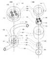
- FIG. 1Canother type of prior art pressure sensor in which a pressure transducer 50 is in pressure communication with an interior 70 of a drip chamber 60 . Blood flows through an inlet tube 65 and out an outlet tube 75 while a trapped volume of air 62 communications pressure to the pressure transducer 50 through a coupling tube 57 .
- An isolator 55protects the pressure transducer 50 by preventing any flow through it via a flexible membrane within it (not shown).
- FIG. 1Ais one type of pressure sensor according to the prior art.
- FIG. 1Bis another type of pressure sensor according to the prior art.
- FIG. 1Cis yet another type of pressure sensor according to the prior art.
- FIG. 2Ais a diagonal projection of two opposing portions of an inventive pressure transducer that detects changes in the shape of a flattened portion of a tube to measure pressure inside the tube.
- FIG. 2Bis an exploded view of the components of the transducer of FIG. 2A .
- FIG. 3Ais a cross-sectional view of the transducer of FIGS. 2A and 2B , showing the opposing parts separated prior to clamping around a portion of a plastic tube.
- FIG. 3Bis a cross-sectional view of the transducer of FIG. 3A , showing the opposing parts in a clamped position suitable for measurement of pressure changes in the plastic tube.
- FIG. 4Ais a diagonal projection of the opposing halves of a pressure transducer suitable for measuring pressure changes in a thin-walled flexible vessel or conduit having large dimensions such that a confining spacing is provided by some external mechanism.
- FIG. 4Bis a diagonal projection of the opposing halves of a pressure transducer suitable for measuring pressure changes in a hanging fluid bag commonly used for biological fluids and having large dimensions such that a confining spacing is provided by some external mechanism.
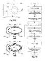
- FIGS. 5A and 5Bare cross-sectional views of circular and elliptical tubes or vessels for purposes of discussing the effect of hoop-strength on pressure measurement.
- FIG. 5Cis a cross-sectional view of a tube or vessel for purposes of discussing the effect of features that increase material strain and thereby impact pressure measurement.
- FIG. 6Ais a cross-sectional view of an example of a tube or vessel configuration for purposes of discussing features that ameliorate pressure measurement even for thick material.
- FIGS. 6B-6Eare cross-sectional views of tubes or vessels for discussing the effect of using thin walls and other features to ameliorate creep effects.
- FIG. 6Fis a cross-sectional view of a tube or vessel for discussing the effect of aspect ratio and other features to ameliorate creep effects.
- FIG. 7is a cross-sectional view of a pressure transducer according to another aspect of the present invention, in which the transducer is shaped so as match a tube or vessel having a non-flat-shaped portion.
- FIG. 8is a cross-sectional view of a pressure transducer that uses a cantilever to transmit pressure changes to a load sensor.
- FIG. 9Ais a cross-sectional view of a pressure transducer that uses a cantilever to transmit pressure changes to a tension transducer or extension displacement transducer.
- FIG. 9Bis a side view of the pressure transducer design of FIG. 9A .
- FIG. 10is a cross-sectional view of a pressure transducer providing a direct contact between a metal plate bearing a strain gage and a flattened portion of a tube or vessel.
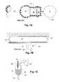
- FIG. 11is a side view of a curved strain gage mounted on a flexible pillar transducer.
- FIG. 12is a cross-sectional view of an alternative mounting mechanism for the anvil employed in the embodiment of FIGS. 2A and 2B and an alternative location for a strain gage.
- FIG. 13Ais a cross-sectional view of a pressure transducer, in which a flexible plate with a strain gage is positioned against a cross-sectional view of a pressure transducer. The pressure transducer is shown in an open position.
- FIG. 13Bis a cross-sectional view of the pressure transducer of FIG. 13A , shown in a closed operating position that enables measurement of pressure changes within the flattened portion.
- FIG. 13Cis another aspect of the pressure transducer of FIG. 13A , in which the pressure transducer is mounted on the base wall. The pressure transducer is shown in an open position.
- FIG. 13Dis a cross-sectional view of the pressure transducer of FIG. 13C , shown in a closed operating position that enables measurement of pressure changes within the flattened portion.
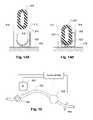
- FIG. 14Ais a cross-sectional view of a pressure transducer, in which a flexible plate with a curved strain gage is positioned to wrap partly around a tube or vessel. The pressure transducer is shown in an open position.
- FIG. 14Bis a cross-sectional view of the pressure transducer of FIG. 14A , shown in a closed operating position that enables measurement of pressure changes within tube or vessel.
- FIG. 15illustrates an automatic calibration configuration for use with various aspects of the present invention.
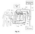
- FIG. 16is a schematic diagram of a blood-processing machine, which may incorporate one or more of the various aspects of the present invention.
- FIG. 17Ais a diagonal view of a blood treatment machine suitable for use with the cartridge of FIG. 17A .
- FIG. 17Bis an illustration of a cartridge and tubing set which is suitable for use in a blood treatment machine.
- FIG. 17Cis an illustration of a pressure transducer suitable for use in the cartridge of FIG. 17B , as mounted in the blood treatment machine of FIG. 17A .
- FIG. 18is a flow chart showing a method for implementing a pressure transducer to make measurements according to one or more aspects of the present invention.
- FIGS. 19A and 19Billustrate certain principles and design features that may be provided to ensure that pressures of fluids at negative gage pressures can be measured.
- a pressure sensor 100includes backing portion 101 that holds a flattened portion 115 of a tube 150 against a sensor portion 102 when the pressure sensor 100 is in a closed operational configuration as shown in FIG. 3B .
- the backing portion 101has springs 105 in a cavity 104 to urge a backing plate 112 against the flattened portion 115 of the tube 150 .
- Standoffs 110provide repeatable spacing in a receiving gap 111 that is defined when the pressure sensor 100 is in the closed operational configuration.
- a surface of the tube 150 flattened portion 115is held against a tip 126 of an anvil 122 held slidably within a guide 127 .
- a backing retainer 103limits a range-of displacement of the backing plate 112 by means of a guide/catch mechanism 170 , which may permit vertical movement of the backing plate 112 relative to the backing retainer 103 .
- the standoffs 110rest against a housing stage 120 as shown in FIG. 3B .
- the springs 150are compressed such that the receiving gap 111 is reliably defined.
- the tube 150 flattened portion 115is shaped such that it is only minimally compressed in the receiving gap 111 . This helps to ensure that while the flattened portion 115 rests in the receiving gap 111 it is minimally strained.
- the flattened portion 115 of the tube 150is supported by the top 123 of the housing stage 120 so that when pressure increase in the flattened portion 115 of the tube 150 , there is minimal strain of material of which the tube 150 is made.
- the flattened portion 115presses against the tip 126 of the anvil 122 forcing the anvil 122 toward a flexible plate 140 with an attached strain gage 145 .
- a pin 135presses against the flexible plate 140 when the anvil 122 is forced toward it by pressure in the tube 150 .
- the amount of strain to which the strain gage 145 is subjectedcan be altered by changing the shape and or size of the pin 135 , due to the differences in the bending moment to which the flexible plate 140 is subjected by displacement of the anvil 122 .
- the pressuremay be measured by means of a curve fitted to a pressure-versus-strain gage signal curve generated by means of a calibration procedure. Calibration is discussed further below.
- the tip 126 of the anvil 122 and the top 123 of the housing stage 120may form a nearly continuous flat surface, with the top 126 jutting only slightly above the top 123 of the housing stage 120 . In this way, the deformation of the flattened portion 115 of the tube 150 may be minimal. This may be a benefit where the material of the tube 150 is subject to creep. Also, the overall configuration may be such that the displacement of the anvil 122 may have a low magnitude to help reduce the potential creep problem.
- the pressure sensor 100may be used detect pressure in a variety of vessels other than a tube 150 .
- a flexible chamber 215 connected to, or connectable to, a flow conduit (not shown) by flow lines 225 and 220may have very flexible walls 205 reducing the magnitude of the potential creep problem.
- Backing 101 and sensor 102 portions without standoffs 110may be brought into a desired relationship by a suitable structure such that when pressure is applied to fluid in the flexible chamber 215 , the anvil 122 is forced toward the flexible plate 140 thereby permitting measurement of pressure by means of the strain indicated by the strain gage 145 .
- portions of the flexible chamber 215 outside that subtended by the backing 101 and sensor 102 portions of the pressure sensor 100may be confined in a recess defined by walls of a machine (e. g., a renal therapy machine as described in U.S. Pat. Ser. Nos. 09/513,564, 09/512,927, and 09/513,773 hereby incorporated by reference in their entirety as fully set forth herein).
- a machinee. g., a renal therapy machine as described in U.S. Pat. Ser. Nos. 09/513,564, 09/512,927, and 09/513,773 hereby incorporated by reference in their entirety as fully set forth herein.
- Such wallsmay be substantially coplanar with the backing plate 112 and the top 123 of the housing stage 120 .
- Pressuremay also be measured in a fixed vessel such as shown at 235 , which defines, flow-wise, a dead-end.
- FIGS. 5A through 5C and 6 A through 6 Fillustrate vessels or tubes of a variety of configurations for purposes of illustrating various features that may influence the design of a pressure sensor according to the embodiments disclosed and variations thereof.
- a vessel or tube 250 with a substantially circular cross-sectionhas significant hoop strength requiring a great deal of material strain to displace a contact sensor such as the anvil 122 described with reference to the foregoing figures.
- a tube or vessel 255 having an elliptical shapeFIG. 5B
- plastic tubing 260 of a generally oval shape with rigidity-enhancing ridges 256as shown in FIG. 5C .
- the thickness of the wallsaffects the degree of strain to which the material of the tube or vessel must be subjected to generate a displacement for actuating the foregoing embodiments and others described elsewhere in the instant specification.
- the tubes or vessels 250 , 255 , and 260 shown aboveare illustrated in a relaxed state.
- the tubes or vessels 250 , 255 , and 260may be compressed to force an outer surface against the tip 253 of an anvil and housing stage surface 252 to preload the tube or vessel 250 , 255 , and 260 or not.
- the creepmay play a significant role in the deformation of the tube or vessel 250 , 255 , and 260 .
- the tube or vessel 250 , 255 , and 260may gradually deform thereby generating a lower elastic rebound over time making the pressure signal from calibration less related to the pressure signal after calibration. If not preloaded, the variation of shape due to pressure change would tend to cause the same effect, namely, a time-varying response due to gradual accommodation to a current shape.
- FIGS. 6C-6Eshow the circular cross-section shapes of FIG. 5A with thinner walls that the embodiment of FIG. 5A .
- FIGS. 6D and 6Eshow the elliptical and complex cross-section shapes of FIGS. 5B and 5C with thinner walls.
- FIG. 6Cillustrates preloading of the circular cross-section tube or vessel 250 A by compressing the latter between a backing surface 254 and an anvil 253 and stage 252 combination forming an opposing surface. If the tube or vessel 250 A has substantial strength and elasticity, negative gage pressures may be measured and preloading may be used to select the response characteristic.
- the contact area for the pressure sensoris increased.
- preload strainbecomes less of a problem and any pressure changes within the it are transmitted more quickly and reliably to the pressure sensor.
- a thick-walled tube 270 having a flattened portion 272provides an enhanced area that contacts not only the central portion 253 of pressure sensor 251 , but also the outer portions 252 as well ( FIG. 6A ).
- a thin-walled tube 265 having the same conformation as that of FIG. 6Anot only provides the enhanced contact area for pressure sensor 253 , but also further produces little strain, resulting in a greatly reduced amount of creep.
- a thin walled circular tube 250 A illustrated in FIG. 6Cis flattened between backing surface 254 and pressure sensor 251 causing the thin-walled circular tube 250 A to form a more oval shape.
- a thin walled elliptical tube 255 A illustrated in FIG. 6Dis flattened by backing surface 254 and the pressure sensor 251 .
- the strain at the site of contact of pressure sensor 251may be reduced even in the presence of rigidity-enhancing ridges 256 A.
- a portion of a circular or elliptical piece of tubingmay be flattened at the point of contact with pressure sensor 253 to provide the enhanced contact area. The flattened portion may be created by physical alteration of the tubing, or by incorporation of a different piece of tubing that is flatter than the rest of the tubing.
- One method of creating the flattened portion of a tubesuch as the flattened portion 272 of the tube 270 shown in FIG. 6A is to thermoform a cylindrical tube by heating and compressing it.
- the flattened portionmay also be thinner than the rest of the tubing.
- the walls 280 of a non-tubular vessel enclosing a volume 281 with a pressure insidecan be sensed by means of a pressure sensor 251 in a manner similar to the foregoing embodiments.
- creep in a flattened portion of a tube 815may be reduced by arranging the tube in a housing so that the tubing adopts a concave shape where the tubing rests on top of the anvil 810 .
- Tubing 815is held in place atop anvil 810 between backing retainer 820 and housing stage 805 in a formed inner face 830 , and contact anvil 810 at anvil tip 825 .
- the formed inner face 830may have other shapes and may be convex, saddle-shaped, or asymmetrical or three dimensional curves in them.
- a cantilever mechanismmay be used to transmit pressure changes to a pressure transducer.
- a flattened portion 330 of a tube 320is held in place between a wall 315 and a fixed base 370 .
- An anvil 340contacts flattened portion 330 .
- the distal end of anvil 340is affixed to an arm 327 of cantilever 325 .
- At the other end of cantilever 325is a knee 335 in contact with a pressure transducer 345 mounted on a fixed base 371 .
- Cantilever 325terminates at and is fixed to a fixed base 310 . Movement of anvil 340 is translated through cantilever arm 327 and is sensed by pressure transducer 345 .
- pressure changesmay be transmitted to an extendible type pressure transducer such as a displacement-type strain gage 385 .
- An arm 355pivots from a fixed hinge 360 .
- An end portion 353 of the arm 355is in contact with a tube 351 such that pressure changes within the tube 351 cause the arm 355 to move.
- the arm 355 movementsare transmitted to a displacement-type strain gage 385 connected between the arm 355 and a fixed base 380 .
- the end portion 353 of the arm 355is surrounded by a fixed base 352 which supports the tube 351 .
- the flattened portion of tubingmay directly contact a strain gauge and flexible plate.
- the devicefunctions without an anvil, cantilever, etc., to transmit the detected pressure changes to a pressure transducer.
- flattened portion 460is held in place between a wall 465 and flexible plate 455 atop a strain gage 450 mounted on a fixed base 475 . Movement in flexible plate 455 is transmitted directly to strain gage 450 .
- the pressure changeis sensed by a curved strain gauge mounted on a flexible pillar transducer, as shown in FIG. 11 .
- Tubing flattened portion 485is mounted between a wall 486 and a flat terminus 483 of a flexible pillar transducer 482 .
- Flexible pillar transducer 482is held in contact with tubing flattened portion 485 by the flexible pillar, which urges the terminus 483 against the tubing flat portion 485 .
- the other end of flexible pillar transducer 482is attached to a fixed base 488 .
- Attached to the outside surface of flexible pillar transducer 482 , between the arm attached to pressure sensor 484 and the arm attached to wall 488is a strain gauge 480 . Pressure changes in tubing flattened portion 485 produce a change in the shape of flexible pillar transducer 482 , which is detectable by the strain gauge 480 .
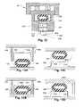
- anvil 122may be subject to frictional resistance to movement within housing stage 120 . Such resistance to movement may result in loss of sensitivity or an apparent “spike” in pressure as the anvil suddenly overcomes the resistance.
- the devicemay be constructed to reduce frictional contact between anvil 122 and housing stage 120 .
- anvil 522is held within housing stage 505 with one or more rings 530 .
- rings 530a total of two internal rings are shown, it is intended that any number of rings 530 could be employed consistent with the goal of reducing frictional contact with anvil 522 while maintaining anvil 522 in a fixed position at rest.
- FIG. 3Bwhen fluid in the tube 555 is pressurized, the flattened portion presses against the anvil 522 , forcing plunger 520 toward a flexible plate 535 with attached strain gauge 540 .
- one or more strain gages 541may be mounted on rings 525 to detect pressurization of tube 555 .
- the pressure transduceris in the form of a strain gage mounted on a flexible plate that contacts the flattened portion of a tube 555 mounted on a wall 565 .
- a flexible plate 550is mounted between one or more standoffs 585 .
- a strain gauge 570is mounted on flexible plate 550 , at a position where flexible plate 550 contacts the flattened portion of tube 555 when standoffs 585 are lowered to contact wall 565 , as shown in FIG. 13B .
- FIGS. 13C and 13DAnother aspect of the invention is shown in FIGS. 13C and 13D , in which tube 555 is mounted between standoffs 585 , and a flexible plate 550 is mounted on wall 565 .
- a strain gage 570is mounted on flexible plate 550 , and contacts the flattened portion of tube 555 when tube 555 is lowered so that standoff 585 contacts wall 565 .
- FIGS. 13A and 13Bshow two standoffs in opposing position, and FIGS. 13C and 13D show a single standoff, it is intended that the present invention not be limited to these embodiments. For example, more than two standoffs may be used, and they may be regularly or irregularly spaced.
- strain gauge 570is shown in FIGS. 13 A through 13 D as being located in the center of flexible plate 550 , it may be mounted at any point along flexible plate 550 where flexible plate 550 contacts the flattened portion of tube 555 .
- FIGS. 14A and 14Billustrate yet another aspect of the present invention, in which a transducer having a flexible plate and bearing a curved strain gauge is positioned to wrap partly around a tube or vessel.
- flexible plate 620is mounted between a pair of opposing side supports 610 , such that it forms a curved shape between side supports 610 .
- Flexible plate 620may be mounted on a wall 630 , as shown.
- the curved shape of flexible plate 620matches the outside curve of a tube 605 .
- a curved strain gauge 625is mounted on flexible plate 620 , such that tube 605 may fit inside and in contact with flexible plate 620 . Strain gauge 625 is located on the outside portion of flexible plate 620 .
- Calibration of the pressure sensormay be achieved by a standard curve-fitting procedure using a calibration system.
- a calibration systemincludes a pump 660 connected via a tube 645 to a pressure sensor 650 .
- the rate of fluid flow through the tubing 645 and the pressure sensor 650is controlled by either or both of the pump 660 or a clamp 665 downstream from the pressure sensor 650 .
- the pump 660 and the clamp 665are controlled by a controller 655 .
- a precalibrated pressure sensor 640is located in the tubing line between the pump 660 and the clamp 665 .
- the controller 655establishes a predetermined internal pressure from precalibrated pressure sensor 640 by altering the flow rate of pump 660 or the degree of closure of clamp 665 , or both.
- the controller 655measures the output from pressure sensor 650 , and associates the output with the predetermined pressure.
- the processis performed for at least two different pressure settings, and the results are used to establish a calibration curve for the pressure sensor 650 (i. e., output of pressure sensor 650 vs. pressure).
- a number of configurationsare preferred for use with the pressure sensor as well as others discussed in the instant specification.
- the preferred configurationmay depend on various features, including the material from which the tube or vessel is made, the thickness of the tube or vessel wall relative to the top of the anvil, the shape of the wall, the length of time during which the tube or vessel is subjected to pressure, the amount of pressure to which the tube or vessel is subjected, the conformity of the surface defined by the top of the anvil and the top of the housing stage.
- Controller 655regulates the flow rate of pumps 710 , 744 , 746 , and 747 to flow blood from the patient, through a hemofilter 715 , and then back to the patient.
- the machineincludes a blood handling unit, a fluid management unit, and a ultrafiltration unit.
- the blood-handling unitcirculates the patient's blood in a controlled manner through the hemofilter 715 and back to the patient after treatment.
- the hemofilter 715may be a dialyzer as well.
- the hemofilter 715removes waste fluid, containing urea and other toxins, from the blood.
- the fluid management unitreplaces the waste fluid with a sterile replacement fluid for return with the treated blood to the patient's blood supply.
- the replacement fluidalso acts to maintain the patient's electrolytic balance and acid/base balance.
- the ultrafiltration unitremoves waste fluid from the patient without the need for addition of replacement fluid.
- blood from the patient 725is pumped by pump 710 through hemofilter 715 via arterial blood supply line 727 , and then returned to the patient 725 via venous return line 729 . Wastes, including liquid and uremic toxins, are separated by the hemofilter 715 from the rest of the blood.
- Various valves, pumps and sensorsare employed to determine and deliver the appropriate amount of replacement fluid required to insert into the venous return line to maintain the patient's blood pressure.
- the pressure sensor 705 of the present inventionis placed in the venous return line to measure venous pressure in the patient's return blood line.
- FIG. 17Aillustrates a blood treatment machine 800 that may incorporate the pressure sensor of the present invention.
- FIG. 17Billustrates a cartridge 805 that is insertable in a space 915 in the blood treatment machine 900 .
- the blood treatment machine 800has a first portion 920 that closes in a clamshell fashion onto a second portion 925 causing various actuators and sensors 940 to engage tubing and other components 945 held by the cartridge 805 .
- a sensora portion of which is visible at 905 , which contacts a flattened tube portion 910 supported by the cartridge 805 .
- the cartridge 805may be disposable.
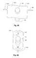
- FIG. 17Cshows an enlarged view of the flattened tube portion 910 , which may be in a venous return line of the cartridge of FIG. 17A .
- a portion of the cartridge 805supports a tube 815 with the flattened tube portion 910 that engages the sensor partly visible at 905 .
- the portion 910may be cylindrical rather than flattened as indicated or its flattened dimension may be oriented differently depending on the configuration of the sensor with which it is configured to mate.
- An opening 810may be provided to give the sensor (partly shown at 905 ) access to the portion flattened portion 910 .
- the cartridgemay or may not have a panel 825 , that is, it may be an open support structure (not illustrated).
- FIG. 18provides a flowchart that illustrates a procedure for standardizing the pressure sensor described above.
- the circuitis first primed (S 10 ), then the lines are closed off or pinched and the pump maintains a first flow rate (S 15 ).
- the controllerthen takes a first pressure reading from 640 of FIG. 15 and a P signal (S 20 ) which may be a voltage signal from a pressure transducer of any of the foregoing embodiments.
- the pump flow ratethen is changed to a second flow rate different from the first flow rate (S 25 ), and after the system re-equilibrates the controller takes a second pressure reading and a second P signal (S 30 ).
- the systemchecks to determine if the required number of data points has been collected (S 32 ).
- steps S 25 , S 30 and S 32are repeated until the required number of data points is collected. At that point, the data points collected are used to generate a standard curve (S 35 ) by conventional statistical methods.
- the signals obtained during the runare converted to pressure values by fitting the P signals to the standard curve (S 40 ).
- any of the foregoing embodimentsit is possible to provide for some preload of the vessel/tube or support thereof such that when there is a negative pressure in the vessel/tube, it does not collapse. Under such circumstances, any of the above embodiments may allow for the measurement of negative gage pressures in the same manner as positive gage pressure is measured. Certain kinds of vessels/tubes would not provide a substantial preload without an external support, however, for example thin-walled vessels/tubes or those with walls with large area relative to thickness.
- a vessel or tube 845has molded portions 830 that engage with arms 835 of a spring 850 .
- the spring 850has attached to a base portion 860 thereof, a strain sensor 840 to detect changes in shape of the spring 850 .
- the engagement between the spring 850 and molded portions 830is such that if a negative pressure develops within an interior 855 of the vessel or tube 845 , the tendency of the vessel or tube 845 to collapse may be resisted by the spring 850 .
- it may be that the resilience of the spring 850ensures against collapse of the vessel or tube 845 if the vessel or tube 845 lacks sufficient integrity to avoid collapse with the help of the spring 850 .
- the spring 850would relax when there is zero gage pressure in the interior 855 and would experience reverse tension when the interior pressure dropped below gage pressure. But the same result may be achieved even if the spring were always under tension in the same direction as positive if the structure of the vessel or tube is such that a positive preloading is presented to the spring.
- a thick-walled vessel or tube 860is squeezed by a spring 870 , the force of the spring being resisted by the vessel or tube 860 even when its interior 857 is under negative pressure.
- the pressure sensors of at least some of the earlier embodimentsmay be altered as illustrated by the examples of FIGS. 19A and 19B to provide for measurement of negative pressure.
- a third springfor example, one mounted inside the vessel or tube.
- load cells and strain gagesare disclosed as a preferred mechanism for detecting shape change of fluid vessels or tubes, it is possible to detect such shape change by other means.
- any kind of displacement transducersuch as a mechanical, resistance, or optical encoder could be used to measure the change in shape of the tube or vessel due to pressure variation.
- non-contact detectorscould be used, for example, an interferometric displacement encoder.
Landscapes
- Health & Medical Sciences (AREA)
- Vascular Medicine (AREA)
- Heart & Thoracic Surgery (AREA)
- Biomedical Technology (AREA)
- Life Sciences & Earth Sciences (AREA)
- Veterinary Medicine (AREA)
- Engineering & Computer Science (AREA)
- Anesthesiology (AREA)
- Public Health (AREA)
- Hematology (AREA)
- Cardiology (AREA)
- Animal Behavior & Ethology (AREA)
- General Health & Medical Sciences (AREA)
- Physics & Mathematics (AREA)
- General Physics & Mathematics (AREA)
- Measuring Fluid Pressure (AREA)
- External Artificial Organs (AREA)
Abstract
Description
Claims (10)
Priority Applications (1)
| Application Number | Priority Date | Filing Date | Title |
|---|---|---|---|
| US11/160,586US7337674B2 (en) | 2005-06-29 | 2005-06-29 | Pressure detector for fluid circuits |
Applications Claiming Priority (1)
| Application Number | Priority Date | Filing Date | Title |
|---|---|---|---|
| US11/160,586US7337674B2 (en) | 2005-06-29 | 2005-06-29 | Pressure detector for fluid circuits |
Publications (2)
| Publication Number | Publication Date |
|---|---|
| US20070000333A1 US20070000333A1 (en) | 2007-01-04 |
| US7337674B2true US7337674B2 (en) | 2008-03-04 |
Family
ID=37587953
Family Applications (1)
| Application Number | Title | Priority Date | Filing Date |
|---|---|---|---|
| US11/160,586Active2025-12-13US7337674B2 (en) | 2005-06-29 | 2005-06-29 | Pressure detector for fluid circuits |
Country Status (1)
| Country | Link |
|---|---|
| US (1) | US7337674B2 (en) |
Cited By (31)
| Publication number | Priority date | Publication date | Assignee | Title |
|---|---|---|---|---|
| US20090076434A1 (en)* | 2007-09-13 | 2009-03-19 | Mischelevich David J | Method and System for Achieving Volumetric Accuracy in Hemodialysis Systems |
| US20090101552A1 (en)* | 2007-09-25 | 2009-04-23 | Fulkerson Barry N | Manifolds for Use in Conducting Dialysis |
| US20090101577A1 (en)* | 2007-09-28 | 2009-04-23 | Fulkerson Barry N | Methods and Systems for Controlling Ultrafiltration Using Central Venous Pressure Measurements |
| US20090114037A1 (en)* | 2007-10-11 | 2009-05-07 | Mark Forrest Smith | Photo-Acoustic Flow Meter |
| US20100116740A1 (en)* | 2007-11-29 | 2010-05-13 | Barry Neil Fulkerson | Priming System and Method for Dialysis Systems |
| US20100116048A1 (en)* | 2007-10-11 | 2010-05-13 | Barry Neil Fulkerson | Thermal Flow Meter |
| US20100184198A1 (en)* | 2009-01-16 | 2010-07-22 | Joseph Russell T | Systems and Methods of Urea Processing to Reduce Sorbent Load |
| US20100234786A1 (en)* | 2009-02-12 | 2010-09-16 | Barry Neil Fulkerson | System and Method for Detection of Disconnection in an Extracorporeal Blood Circuit |
| US20110054378A1 (en)* | 2009-02-26 | 2011-03-03 | Barry Neil Fulkerson | Methods and Systems for Measuring and Verifying Additives for Use in a Dialysis Machine |
| US8114288B2 (en) | 2007-11-29 | 2012-02-14 | Fresenlus Medical Care Holdings, Inc. | System and method for conducting hemodialysis and hemofiltration |
| US8240636B2 (en) | 2009-01-12 | 2012-08-14 | Fresenius Medical Care Holdings, Inc. | Valve system |
| US8597505B2 (en) | 2007-09-13 | 2013-12-03 | Fresenius Medical Care Holdings, Inc. | Portable dialysis machine |
| US20150233770A1 (en)* | 2014-02-17 | 2015-08-20 | General Electric Company | Cooktop temperature sensors and methods of operation |
| US9157786B2 (en) | 2012-12-24 | 2015-10-13 | Fresenius Medical Care Holdings, Inc. | Load suspension and weighing system for a dialysis machine reservoir |
| US9199022B2 (en) | 2008-09-12 | 2015-12-01 | Fresenius Medical Care Holdings, Inc. | Modular reservoir assembly for a hemodialysis and hemofiltration system |
| US9308307B2 (en) | 2007-09-13 | 2016-04-12 | Fresenius Medical Care Holdings, Inc. | Manifold diaphragms |
| US9328969B2 (en) | 2011-10-07 | 2016-05-03 | Outset Medical, Inc. | Heat exchange fluid purification for dialysis system |
| US9354640B2 (en) | 2013-11-11 | 2016-05-31 | Fresenius Medical Care Holdings, Inc. | Smart actuator for valve |
| US9358331B2 (en) | 2007-09-13 | 2016-06-07 | Fresenius Medical Care Holdings, Inc. | Portable dialysis machine with improved reservoir heating system |
| US9402945B2 (en) | 2014-04-29 | 2016-08-02 | Outset Medical, Inc. | Dialysis system and methods |
| US9433720B2 (en) | 2013-03-14 | 2016-09-06 | Fresenius Medical Care Holdings, Inc. | Universal portable artificial kidney for hemodialysis and peritoneal dialysis |
| US9545469B2 (en) | 2009-12-05 | 2017-01-17 | Outset Medical, Inc. | Dialysis system with ultrafiltration control |
| US9551625B2 (en) | 2011-05-31 | 2017-01-24 | Nxstage Medical, Inc. | Pressure measurement devices, methods, and systems |
| US10035103B2 (en) | 2008-10-30 | 2018-07-31 | Fresenius Medical Care Holdings, Inc. | Modular, portable dialysis system |
| US10792414B2 (en) | 2013-03-14 | 2020-10-06 | Fresenius Medical Care Holdings, Inc. | Universal portable machine for online hemodiafiltration using regenerated dialysate |
| US10864312B2 (en) | 2005-11-09 | 2020-12-15 | B. Braun Medical Inc. | Diaphragm pressure pod for medical fluids |
| US11525798B2 (en) | 2012-12-21 | 2022-12-13 | Fresenius Medical Care Holdings, Inc. | Method and system of monitoring electrolyte levels and composition using capacitance or induction |
| US11534537B2 (en) | 2016-08-19 | 2022-12-27 | Outset Medical, Inc. | Peritoneal dialysis system and methods |
| US11724013B2 (en) | 2010-06-07 | 2023-08-15 | Outset Medical, Inc. | Fluid purification system |
| US12201762B2 (en) | 2018-08-23 | 2025-01-21 | Outset Medical, Inc. | Dialysis system and methods |
| US12390565B2 (en) | 2019-04-30 | 2025-08-19 | Outset Medical, Inc. | Dialysis systems and methods |
Families Citing this family (16)
| Publication number | Priority date | Publication date | Assignee | Title |
|---|---|---|---|---|
| US20120302938A1 (en)* | 2010-03-19 | 2012-11-29 | University Of Washington | Drainage systems for excess body fluids and associated methods |
| CA2793672C (en) | 2010-03-19 | 2020-08-04 | University Of Washington | Drainage systems for excess body fluids |
| GB2498124A (en)* | 2010-09-23 | 2013-07-03 | Nxstage Medical Inc | Pressure sensing methods, devices, and systems |
| TWI421481B (en)* | 2011-06-24 | 2014-01-01 | Universal Cement Corp | Preloaded pressure sensor module |
| EP2737917B1 (en)* | 2012-11-29 | 2018-03-21 | Gambro Lundia AB | Extracorporeal blood circuit with non-invasive pressure sensor |
| CN104363935B (en) | 2012-12-14 | 2017-06-20 | 甘布罗伦迪亚股份公司 | Diaphragm Repositioning for Pressure Cassettes Using Position Sensing |
| DE102013105037A1 (en)* | 2013-05-16 | 2014-11-20 | Eucatech Ag | Generation of pressure fluctuations in a pipe |
| US10463264B2 (en) | 2013-10-15 | 2019-11-05 | Aqueduct Critical Care, Inc. | Pressure/force sensors having a flexible membrane, dynamic and static pressure/force sensor calibration methods |
| AU2015206267B2 (en) | 2014-01-16 | 2018-02-01 | Aqueduct Neurosciences, Inc. | Pressure reference assemblies for body fluid drainage systems and associated methods |
| WO2015157320A1 (en)* | 2014-04-07 | 2015-10-15 | Browd Samuel R | Implantable self-calibrating sensor assemblies and associated methods |
| WO2017104158A1 (en) | 2015-12-14 | 2017-06-22 | テルモ株式会社 | Removable pressure sensor and extracorporeal circulation device provided with removable pressure sensor |
| US9797759B2 (en)* | 2016-01-13 | 2017-10-24 | The Boeing Company | Integrated pipe pressure and temperature sensors and related methods |
| CN110431393A (en)* | 2017-03-29 | 2019-11-08 | Tdk株式会社 | Fluid pressure test device |
| CN110446915A (en)* | 2017-03-29 | 2019-11-12 | Tdk株式会社 | Fluid pressure test device |
| CN110715765B (en)* | 2019-11-08 | 2025-02-14 | 武汉飞恩微电子有限公司 | A pressure sensor for preventing backflow |
| WO2024157979A1 (en)* | 2023-01-23 | 2024-08-02 | ニプロ株式会社 | Pressure measurement unit, diaphragm chamber, and blood circuit |
Citations (16)
| Publication number | Priority date | Publication date | Assignee | Title |
|---|---|---|---|---|
| US3046788A (en)* | 1960-08-04 | 1962-07-31 | Baldwin Lima Hamilton Corp | Fluid pressure electrical transducer |
| US4207551A (en)* | 1976-03-12 | 1980-06-10 | Hans Kautzky | Pressure transducer |
| US4555949A (en)* | 1984-05-04 | 1985-12-03 | Anatros Corporation | Optical fluid pressure sensor |
| US4576181A (en) | 1984-05-09 | 1986-03-18 | Utah Medical Products | Disposable pressure transducer apparatus for medical use |
| US5024099A (en) | 1989-11-20 | 1991-06-18 | Setra Systems, Inc. | Pressure transducer with flow-through measurement capability |
| US5440932A (en)* | 1993-01-05 | 1995-08-15 | Dynisco, Inc. | Pressure transducer including coaxial rings |
| US5602339A (en)* | 1994-03-24 | 1997-02-11 | Dynisco, Inc. | Injection molding machine pressure transducer with trapezoidal cavity |
| US5846257A (en)* | 1997-08-15 | 1998-12-08 | Nexus Medical System, Inc. Llc | Pressure sensor for a surgical system |
| US6463813B1 (en)* | 1999-06-25 | 2002-10-15 | Weatherford/Lamb, Inc. | Displacement based pressure sensor measuring unsteady pressure in a pipe |
| US6523414B1 (en) | 2001-04-16 | 2003-02-25 | Zevex, Inc. | Optical pressure monitoring system |
| US6579253B1 (en) | 1997-02-14 | 2003-06-17 | Nxstage Medical, Inc. | Fluid processing systems and methods using extracorporeal fluid flow panels oriented within a cartridge |
| US6638478B1 (en) | 1997-02-14 | 2003-10-28 | Nxstage Medical, Inc. | Synchronized volumetric fluid balancing systems and methods |
| US20040060359A1 (en)* | 2002-09-18 | 2004-04-01 | Wilson James Brian | Pressure sensing apparatus |
| US6857326B2 (en)* | 2002-09-04 | 2005-02-22 | Key Safety Systems, Inc. | Device for measuring force acting upon a seat belt |
| US6957588B1 (en)* | 1999-06-28 | 2005-10-25 | Thomas P. Kicher & Co. | Fluid measuring device and method |
| US7056316B1 (en)* | 1997-01-21 | 2006-06-06 | Vasca, Inc. | Valve port and method for vascular access |
- 2005
- 2005-06-29USUS11/160,586patent/US7337674B2/enactiveActive
Patent Citations (18)
| Publication number | Priority date | Publication date | Assignee | Title |
|---|---|---|---|---|
| US3046788A (en)* | 1960-08-04 | 1962-07-31 | Baldwin Lima Hamilton Corp | Fluid pressure electrical transducer |
| US4207551A (en)* | 1976-03-12 | 1980-06-10 | Hans Kautzky | Pressure transducer |
| US4555949A (en)* | 1984-05-04 | 1985-12-03 | Anatros Corporation | Optical fluid pressure sensor |
| US4576181A (en) | 1984-05-09 | 1986-03-18 | Utah Medical Products | Disposable pressure transducer apparatus for medical use |
| US5024099A (en) | 1989-11-20 | 1991-06-18 | Setra Systems, Inc. | Pressure transducer with flow-through measurement capability |
| US5440932A (en)* | 1993-01-05 | 1995-08-15 | Dynisco, Inc. | Pressure transducer including coaxial rings |
| US5602339A (en)* | 1994-03-24 | 1997-02-11 | Dynisco, Inc. | Injection molding machine pressure transducer with trapezoidal cavity |
| US7056316B1 (en)* | 1997-01-21 | 2006-06-06 | Vasca, Inc. | Valve port and method for vascular access |
| US6638478B1 (en) | 1997-02-14 | 2003-10-28 | Nxstage Medical, Inc. | Synchronized volumetric fluid balancing systems and methods |
| US6579253B1 (en) | 1997-02-14 | 2003-06-17 | Nxstage Medical, Inc. | Fluid processing systems and methods using extracorporeal fluid flow panels oriented within a cartridge |
| US6589482B1 (en) | 1997-02-14 | 2003-07-08 | Nxstage Medical, Inc. | Extracorporeal circuits for performing hemofiltration employing pressure sensing without an air interface |
| US5846257A (en)* | 1997-08-15 | 1998-12-08 | Nexus Medical System, Inc. Llc | Pressure sensor for a surgical system |
| US6463813B1 (en)* | 1999-06-25 | 2002-10-15 | Weatherford/Lamb, Inc. | Displacement based pressure sensor measuring unsteady pressure in a pipe |
| US6957588B1 (en)* | 1999-06-28 | 2005-10-25 | Thomas P. Kicher & Co. | Fluid measuring device and method |
| US6523414B1 (en) | 2001-04-16 | 2003-02-25 | Zevex, Inc. | Optical pressure monitoring system |
| US7121143B2 (en)* | 2001-04-16 | 2006-10-17 | Zevex, Inc. | Optical pressure monitoring system |
| US6857326B2 (en)* | 2002-09-04 | 2005-02-22 | Key Safety Systems, Inc. | Device for measuring force acting upon a seat belt |
| US20040060359A1 (en)* | 2002-09-18 | 2004-04-01 | Wilson James Brian | Pressure sensing apparatus |
Cited By (79)
| Publication number | Priority date | Publication date | Assignee | Title |
|---|---|---|---|---|
| US10864312B2 (en) | 2005-11-09 | 2020-12-15 | B. Braun Medical Inc. | Diaphragm pressure pod for medical fluids |
| US11071811B2 (en) | 2007-09-13 | 2021-07-27 | Fresenius Medical Care Holdings, Inc. | Portable dialysis machine |
| US10258731B2 (en) | 2007-09-13 | 2019-04-16 | Fresenius Medical Care Holdings, Inc. | Manifold diaphragms |
| US9517296B2 (en) | 2007-09-13 | 2016-12-13 | Fresenius Medical Care Holdings, Inc. | Portable dialysis machine |
| US10383993B2 (en) | 2007-09-13 | 2019-08-20 | Fresenius Medical Care Holdings, Inc. | Pump shoe for use in a pumping system of a dialysis machine |
| US10596310B2 (en) | 2007-09-13 | 2020-03-24 | Fresenius Medical Care Holdings, Inc. | Portable dialysis machine |
| US9358331B2 (en) | 2007-09-13 | 2016-06-07 | Fresenius Medical Care Holdings, Inc. | Portable dialysis machine with improved reservoir heating system |
| US9308307B2 (en) | 2007-09-13 | 2016-04-12 | Fresenius Medical Care Holdings, Inc. | Manifold diaphragms |
| US11318248B2 (en) | 2007-09-13 | 2022-05-03 | Fresenius Medical Care Holdings, Inc. | Methods for heating a reservoir unit in a dialysis system |
| US20090076434A1 (en)* | 2007-09-13 | 2009-03-19 | Mischelevich David J | Method and System for Achieving Volumetric Accuracy in Hemodialysis Systems |
| US10857281B2 (en) | 2007-09-13 | 2020-12-08 | Fresenius Medical Care Holdings, Inc. | Disposable kits adapted for use in a dialysis machine |
| US8597505B2 (en) | 2007-09-13 | 2013-12-03 | Fresenius Medical Care Holdings, Inc. | Portable dialysis machine |
| US11224841B2 (en) | 2007-09-25 | 2022-01-18 | Fresenius Medical Care Holdings, Inc. | Integrated disposable component system for use in dialysis systems |
| US9352282B2 (en) | 2007-09-25 | 2016-05-31 | Fresenius Medical Care Holdings, Inc. | Manifolds for use in conducting dialysis |
| US20090101552A1 (en)* | 2007-09-25 | 2009-04-23 | Fulkerson Barry N | Manifolds for Use in Conducting Dialysis |
| US8105487B2 (en) | 2007-09-25 | 2012-01-31 | Fresenius Medical Care Holdings, Inc. | Manifolds for use in conducting dialysis |
| US10022673B2 (en) | 2007-09-25 | 2018-07-17 | Fresenius Medical Care Holdings, Inc. | Manifolds for use in conducting dialysis |
| US20090101577A1 (en)* | 2007-09-28 | 2009-04-23 | Fulkerson Barry N | Methods and Systems for Controlling Ultrafiltration Using Central Venous Pressure Measurements |
| US20100331754A1 (en)* | 2007-09-28 | 2010-12-30 | Fresenius Medical Care Holding | Method and Systems for Controlling Ultrafiltration Using Central Venous Pressure Measurements |
| US8395761B2 (en) | 2007-10-11 | 2013-03-12 | Fresenius Medical Care Holdings, Inc. | Thermal flow meter |
| US8040493B2 (en) | 2007-10-11 | 2011-10-18 | Fresenius Medical Care Holdings, Inc. | Thermal flow meter |
| US20090114037A1 (en)* | 2007-10-11 | 2009-05-07 | Mark Forrest Smith | Photo-Acoustic Flow Meter |
| US20100116048A1 (en)* | 2007-10-11 | 2010-05-13 | Barry Neil Fulkerson | Thermal Flow Meter |
| US10758662B2 (en) | 2007-11-29 | 2020-09-01 | Fresenius Medical Care Holdings, Inc. | Priming system and method for dialysis systems |
| US8771511B2 (en) | 2007-11-29 | 2014-07-08 | Fresenius Medical Care Holdings, Inc. | Disposable apparatus and kit for conducting dialysis |
| US8137553B2 (en) | 2007-11-29 | 2012-03-20 | Fresenius Medical Care Holdings, Inc. | Priming system and method for dialysis systems |
| US10034973B2 (en) | 2007-11-29 | 2018-07-31 | Fresenius Medical Care Holdings, Inc. | Disposable apparatus and kit for conducting dialysis |
| US9295772B2 (en) | 2007-11-29 | 2016-03-29 | Fresenius Medical Care Holdings, Inc. | Priming system and method for dialysis systems |
| US8114288B2 (en) | 2007-11-29 | 2012-02-14 | Fresenlus Medical Care Holdings, Inc. | System and method for conducting hemodialysis and hemofiltration |
| US10758661B2 (en) | 2007-11-29 | 2020-09-01 | Fresenius Medical Care Holdings, Inc. | Disposable apparatus and kit for conducting dialysis |
| US11439738B2 (en) | 2007-11-29 | 2022-09-13 | Fresenius Medical Care Holdings, Inc. | Methods and Systems for fluid balancing in a dialysis system |
| US9415152B2 (en) | 2007-11-29 | 2016-08-16 | Fresenius Medical Care Holdings, Inc. | Disposable apparatus and kit for conducting dialysis |
| US20100116740A1 (en)* | 2007-11-29 | 2010-05-13 | Barry Neil Fulkerson | Priming System and Method for Dialysis Systems |
| US9199022B2 (en) | 2008-09-12 | 2015-12-01 | Fresenius Medical Care Holdings, Inc. | Modular reservoir assembly for a hemodialysis and hemofiltration system |
| US9759710B2 (en) | 2008-09-12 | 2017-09-12 | Fresenius Medical Care Holdings, Inc. | Modular reservoir assembly for a hemodialysis and hemofiltration system |
| US10670577B2 (en) | 2008-10-30 | 2020-06-02 | Fresenius Medical Care Holdings, Inc. | Modular reservoir assembly for a hemodialysis and hemofiltration system |
| US11169137B2 (en) | 2008-10-30 | 2021-11-09 | Fresenius Medical Care Holdings, Inc. | Modular reservoir assembly for a hemodialysis and hemofiltration system |
| US10035103B2 (en) | 2008-10-30 | 2018-07-31 | Fresenius Medical Care Holdings, Inc. | Modular, portable dialysis system |
| US10758868B2 (en) | 2008-10-30 | 2020-09-01 | Fresenius Medical Care Holdings, Inc. | Methods and systems for leak detection in a dialysis system |
| US10808861B2 (en) | 2009-01-12 | 2020-10-20 | Fresenius Medical Care Holdings, Inc. | Valve system |
| US10197180B2 (en) | 2009-01-12 | 2019-02-05 | Fresenius Medical Care Holdings, Inc. | Valve system |
| US8240636B2 (en) | 2009-01-12 | 2012-08-14 | Fresenius Medical Care Holdings, Inc. | Valve system |
| US9360129B2 (en) | 2009-01-12 | 2016-06-07 | Fresenius Medical Care Holdings, Inc. | Valve system |
| US20100184198A1 (en)* | 2009-01-16 | 2010-07-22 | Joseph Russell T | Systems and Methods of Urea Processing to Reduce Sorbent Load |
| US8535522B2 (en) | 2009-02-12 | 2013-09-17 | Fresenius Medical Care Holdings, Inc. | System and method for detection of disconnection in an extracorporeal blood circuit |
| US20100234786A1 (en)* | 2009-02-12 | 2010-09-16 | Barry Neil Fulkerson | System and Method for Detection of Disconnection in an Extracorporeal Blood Circuit |
| US20110054378A1 (en)* | 2009-02-26 | 2011-03-03 | Barry Neil Fulkerson | Methods and Systems for Measuring and Verifying Additives for Use in a Dialysis Machine |
| US8475399B2 (en) | 2009-02-26 | 2013-07-02 | Fresenius Medical Care Holdings, Inc. | Methods and systems for measuring and verifying additives for use in a dialysis machine |
| US9545469B2 (en) | 2009-12-05 | 2017-01-17 | Outset Medical, Inc. | Dialysis system with ultrafiltration control |
| US11724013B2 (en) | 2010-06-07 | 2023-08-15 | Outset Medical, Inc. | Fluid purification system |
| US9551625B2 (en) | 2011-05-31 | 2017-01-24 | Nxstage Medical, Inc. | Pressure measurement devices, methods, and systems |
| US11529448B2 (en) | 2011-05-31 | 2022-12-20 | Nxstage Medical, Inc. | Pressure measurement devices, methods, and systems |
| US10345175B2 (en) | 2011-05-31 | 2019-07-09 | Nxstage Medical, Inc. | Pressure measurement devices, methods, and systems |
| US12171926B2 (en) | 2011-05-31 | 2024-12-24 | Nxstage Medical, Inc. | Pressure measurement devices, methods, and systems |
| US9835509B2 (en) | 2011-05-31 | 2017-12-05 | Nxstage Medical, Inc. | Pressure measurement devices, methods, and systems |
| US9328969B2 (en) | 2011-10-07 | 2016-05-03 | Outset Medical, Inc. | Heat exchange fluid purification for dialysis system |
| US11525798B2 (en) | 2012-12-21 | 2022-12-13 | Fresenius Medical Care Holdings, Inc. | Method and system of monitoring electrolyte levels and composition using capacitance or induction |
| US10539450B2 (en) | 2012-12-24 | 2020-01-21 | Fresenius Medical Care Holdings, Inc. | Load suspension and weighing system for a dialysis machine reservoir |
| US11187572B2 (en) | 2012-12-24 | 2021-11-30 | Fresenius Medical Care Holdings, Inc. | Dialysis systems with a suspended reservoir |
| US9157786B2 (en) | 2012-12-24 | 2015-10-13 | Fresenius Medical Care Holdings, Inc. | Load suspension and weighing system for a dialysis machine reservoir |
| US10549023B2 (en) | 2013-03-14 | 2020-02-04 | Fresenius Medical Care Holdings, Inc. | Universal portable artificial kidney for hemodialysis and peritoneal dialysis |
| US10792414B2 (en) | 2013-03-14 | 2020-10-06 | Fresenius Medical Care Holdings, Inc. | Universal portable machine for online hemodiafiltration using regenerated dialysate |
| US9433720B2 (en) | 2013-03-14 | 2016-09-06 | Fresenius Medical Care Holdings, Inc. | Universal portable artificial kidney for hemodialysis and peritoneal dialysis |
| US11246972B2 (en) | 2013-03-14 | 2022-02-15 | Fresenius Medical Care Holdings, Inc. | Universal portable machine for online hemodiafiltration using regenerated dialysate |
| US11701459B2 (en) | 2013-03-14 | 2023-07-18 | Fresenius Medical Care Holdings, Inc. | Universal portable artificial kidney for hemodialysis and peritoneal dialysis |
| US10817004B2 (en)* | 2013-11-11 | 2020-10-27 | Fresenius Medical Care Holdings, Inc. | Valve system with a pressure sensing displacement member |
| US9354640B2 (en) | 2013-11-11 | 2016-05-31 | Fresenius Medical Care Holdings, Inc. | Smart actuator for valve |
| US10019020B2 (en) | 2013-11-11 | 2018-07-10 | Fresenius Medical Care Holdings, Inc. | Smart actuator for valve |
| US20190138037A1 (en)* | 2013-11-11 | 2019-05-09 | Fresenius Medical Care Holdings, Inc. | Smart Actuator For Valve |
| US20150233770A1 (en)* | 2014-02-17 | 2015-08-20 | General Electric Company | Cooktop temperature sensors and methods of operation |
| US10018514B2 (en)* | 2014-02-17 | 2018-07-10 | Haier Us Appliance Solutions, Inc. | Cooktop temperature sensors and methods of operation |
| US9504777B2 (en) | 2014-04-29 | 2016-11-29 | Outset Medical, Inc. | Dialysis system and methods |
| US11305040B2 (en) | 2014-04-29 | 2022-04-19 | Outset Medical, Inc. | Dialysis system and methods |
| US9402945B2 (en) | 2014-04-29 | 2016-08-02 | Outset Medical, Inc. | Dialysis system and methods |
| US9579440B2 (en) | 2014-04-29 | 2017-02-28 | Outset Medical, Inc. | Dialysis system and methods |
| US11534537B2 (en) | 2016-08-19 | 2022-12-27 | Outset Medical, Inc. | Peritoneal dialysis system and methods |
| US11951241B2 (en) | 2016-08-19 | 2024-04-09 | Outset Medical, Inc. | Peritoneal dialysis system and methods |
| US12201762B2 (en) | 2018-08-23 | 2025-01-21 | Outset Medical, Inc. | Dialysis system and methods |
| US12390565B2 (en) | 2019-04-30 | 2025-08-19 | Outset Medical, Inc. | Dialysis systems and methods |
Also Published As
| Publication number | Publication date |
|---|---|
| US20070000333A1 (en) | 2007-01-04 |
Similar Documents
| Publication | Publication Date | Title |
|---|---|---|
| US7337674B2 (en) | Pressure detector for fluid circuits | |
| WO2004061399A2 (en) | Pressure detector for fluid circuits | |
| AU737494B2 (en) | Infusion device with disposable elements | |
| CA2029177C (en) | Apparatus for detecting fluid line occlusion | |
| CA2498102C (en) | Testing of pressure sensor in surgical cassette | |
| US6648861B2 (en) | Occlusion detection method and system for ambulatory drug infusion pump | |
| CN100451588C (en) | Pressure detector and pressure detection method | |
| CN104363935A (en) | Diaphragm repositioning for pressure pod using position sensing | |
| CA2144445A1 (en) | Force sensor assembly for pressure measurement for pump | |
| CN113993558A (en) | Medical tubing size scanning | |
| US20230293796A1 (en) | Pressure sensors, including pressure sensors for automated peritoneal dialysis systems, and associated systems, devices, and methods | |
| JP3915474B2 (en) | Pressure detector | |
| WO2020190635A1 (en) | Pressure measurement devices, methods, and systems | |
| CN217366712U (en) | Automatic metering device for peritoneal dialysis liquid exchange | |
| HK1077633B (en) | Pressure detector and pressure detecting method | |
| HK1182974B (en) | Pressure monitoring system for infusion pumps |
Legal Events
| Date | Code | Title | Description |
|---|---|---|---|
| STCF | Information on status: patent grant | Free format text:PATENTED CASE | |
| FEPP | Fee payment procedure | Free format text:PAT HOLDER NO LONGER CLAIMS SMALL ENTITY STATUS, ENTITY STATUS SET TO UNDISCOUNTED (ORIGINAL EVENT CODE: STOL); ENTITY STATUS OF PATENT OWNER: LARGE ENTITY | |
| AS | Assignment | Owner name:GE BUSINESS FINANCIAL SERVICES INC., CONNECTICUT Free format text:SECURITY AGREEMENT;ASSIGNORS:NXSTAGE MEDICAL, INC.;EIR MEDICAL, INC.;MEDISYSTEMS CORPORATION;AND OTHERS;REEL/FRAME:022610/0602 Effective date:20090316 Owner name:GE BUSINESS FINANCIAL SERVICES INC.,CONNECTICUT Free format text:SECURITY AGREEMENT;ASSIGNORS:NXSTAGE MEDICAL, INC.;EIR MEDICAL, INC.;MEDISYSTEMS CORPORATION;AND OTHERS;REEL/FRAME:022610/0602 Effective date:20090316 | |
| AS | Assignment | Owner name:NXSTAGE MEDICAL, INC., MASSACHUSETTS Free format text:RELEASE BY SECURED PARTY;ASSIGNOR:GE BUSINESS FINANCIAL SERVICES INC.;REEL/FRAME:022804/0150 Effective date:20090605 Owner name:EIR MEDICAL, INC., MASSACHUSETTS Free format text:RELEASE BY SECURED PARTY;ASSIGNOR:GE BUSINESS FINANCIAL SERVICES INC.;REEL/FRAME:022804/0150 Effective date:20090605 Owner name:MEDISYSTEMS CORPORATION, MASSACHUSETTS Free format text:RELEASE BY SECURED PARTY;ASSIGNOR:GE BUSINESS FINANCIAL SERVICES INC.;REEL/FRAME:022804/0150 Effective date:20090605 Owner name:MEDISYSTEMS SERVICES CORPORATION, MASSACHUSETTS Free format text:RELEASE BY SECURED PARTY;ASSIGNOR:GE BUSINESS FINANCIAL SERVICES INC.;REEL/FRAME:022804/0150 Effective date:20090605 Owner name:ASAHI KASEI KURARAY MEDICAL CO., LTD., JAPAN Free format text:INTELLECTUAL PROPERTY SECURITY AGREEMENT;ASSIGNORS:NXSTAGE MEDICAL, INC.;EIR MEDICAL, INC.;MEDISYSTEMS CORPORATION;AND OTHERS;REEL/FRAME:022804/0496 Effective date:20090605 Owner name:NXSTAGE MEDICAL, INC.,MASSACHUSETTS Free format text:RELEASE BY SECURED PARTY;ASSIGNOR:GE BUSINESS FINANCIAL SERVICES INC.;REEL/FRAME:022804/0150 Effective date:20090605 Owner name:EIR MEDICAL, INC.,MASSACHUSETTS Free format text:RELEASE BY SECURED PARTY;ASSIGNOR:GE BUSINESS FINANCIAL SERVICES INC.;REEL/FRAME:022804/0150 Effective date:20090605 Owner name:MEDISYSTEMS CORPORATION,MASSACHUSETTS Free format text:RELEASE BY SECURED PARTY;ASSIGNOR:GE BUSINESS FINANCIAL SERVICES INC.;REEL/FRAME:022804/0150 Effective date:20090605 Owner name:MEDISYSTEMS SERVICES CORPORATION,MASSACHUSETTS Free format text:RELEASE BY SECURED PARTY;ASSIGNOR:GE BUSINESS FINANCIAL SERVICES INC.;REEL/FRAME:022804/0150 Effective date:20090605 Owner name:ASAHI KASEI KURARAY MEDICAL CO., LTD.,JAPAN Free format text:INTELLECTUAL PROPERTY SECURITY AGREEMENT;ASSIGNORS:NXSTAGE MEDICAL, INC.;EIR MEDICAL, INC.;MEDISYSTEMS CORPORATION;AND OTHERS;REEL/FRAME:022804/0496 Effective date:20090605 | |
| AS | Assignment | Owner name:SILICON VALLEY BANK,MASSACHUSETTS Free format text:SECURITY AGREEMENT;ASSIGNOR:NXSTAGE MEDICAL, INC.;REEL/FRAME:024114/0789 Effective date:20100310 Owner name:SILICON VALLEY BANK, MASSACHUSETTS Free format text:SECURITY AGREEMENT;ASSIGNOR:NXSTAGE MEDICAL, INC.;REEL/FRAME:024114/0789 Effective date:20100310 | |
| FPAY | Fee payment | Year of fee payment:4 | |
| AS | Assignment | Owner name:GENERAL ELECTRIC CAPITAL CORPORATION, AS ADMINISTR Free format text:SECURITY INTEREST;ASSIGNOR:NXSTAGE MEDICAL, INC.;REEL/FRAME:033123/0836 Effective date:20140609 | |
| AS | Assignment | Owner name:NXSTAGE MEDICAL, INC., MASSACHUSETTS Free format text:RELEASE OF SECURITY INTEREST;ASSIGNOR:SILICON VALLEY BANK;REEL/FRAME:033133/0902 Effective date:20140609 | |
| FPAY | Fee payment | Year of fee payment:8 | |
| AS | Assignment | Owner name:HEALTHCARE FINANCIAL SOLUTIONS, LLC, AS SUCCESSOR Free format text:ASSIGNMENT OF INTELLECTUAL PROPERTY SECURITY AGREEMENT;ASSIGNOR:GENERAL ELECTRIC CAPITAL CORPORATION, AS RETIRING AGENT;REEL/FRAME:037112/0376 Effective date:20151113 | |
| AS | Assignment | Owner name:NXSTAGE MEDICAL, INC., MASSACHUSETTS Free format text:ASSIGNMENT OF ASSIGNORS INTEREST;ASSIGNORS:BRUGGER, JAMES M.;MCDOWELL, CHRISTOPHER S.;BURBANK, JEFFREY H.;AND OTHERS;SIGNING DATES FROM 20170709 TO 20170726;REEL/FRAME:043101/0700 | |
| AS | Assignment | Owner name:NXSTAGE MEDICAL, INC., MASSACHUSETTS Free format text:RELEASE BY SECURED PARTY;ASSIGNOR:ASAHI KASEI MEDICAL CO., LTD. F/K/A ASAHI KASEI KURARAY MEDICAL CO., LTD.;REEL/FRAME:043364/0936 Effective date:20120504 Owner name:MEDISYSTEMS CORPORATION, MASSACHUSETTS Free format text:RELEASE BY SECURED PARTY;ASSIGNOR:ASAHI KASEI MEDICAL CO., LTD. F/K/A ASAHI KASEI KURARAY MEDICAL CO., LTD.;REEL/FRAME:043364/0936 Effective date:20120504 Owner name:MEDISYSTEMS SERVICES CORPORATION, MASSACHUSETTS Free format text:RELEASE BY SECURED PARTY;ASSIGNOR:ASAHI KASEI MEDICAL CO., LTD. F/K/A ASAHI KASEI KURARAY MEDICAL CO., LTD.;REEL/FRAME:043364/0936 Effective date:20120504 | |
| AS | Assignment | Owner name:NXSTAGE MEDICAL, INC., MASSACHUSETTS Free format text:RELEASE BY SECURED PARTY;ASSIGNOR:CAPITAL ONE, NATIONAL ASSOCIATION (AS SUCCESSOR BY MERGER TO HEALTHCARE FINANCIAL SOLUTIONS, LLC);REEL/FRAME:048407/0865 Effective date:20190221 | |
| MAFP | Maintenance fee payment | Free format text:PAYMENT OF MAINTENANCE FEE, 12TH YEAR, LARGE ENTITY (ORIGINAL EVENT CODE: M1553); ENTITY STATUS OF PATENT OWNER: LARGE ENTITY Year of fee payment:12 |