US7336168B2 - System and method for variable threshold sensor - Google Patents
System and method for variable threshold sensorDownload PDFInfo
- Publication number
- US7336168B2 US7336168B2US11/145,880US14588005AUS7336168B2US 7336168 B2US7336168 B2US 7336168B2US 14588005 AUS14588005 AUS 14588005AUS 7336168 B2US7336168 B2US 7336168B2
- Authority
- US
- United States
- Prior art keywords
- sensor
- unit
- sensor system
- units
- repeater
- Prior art date
- Legal status (The legal status is an assumption and is not a legal conclusion. Google has not performed a legal analysis and makes no representation as to the accuracy of the status listed.)
- Expired - Lifetime
Links
Images


Classifications
- G—PHYSICS
- G08—SIGNALLING
- G08B—SIGNALLING OR CALLING SYSTEMS; ORDER TELEGRAPHS; ALARM SYSTEMS
- G08B21/00—Alarms responsive to a single specified undesired or abnormal condition and not otherwise provided for
- G08B21/02—Alarms for ensuring the safety of persons
- G08B21/0202—Child monitoring systems using a transmitter-receiver system carried by the parent and the child
- G08B21/0236—Threshold setting
- G—PHYSICS
- G08—SIGNALLING
- G08B—SIGNALLING OR CALLING SYSTEMS; ORDER TELEGRAPHS; ALARM SYSTEMS
- G08B25/00—Alarm systems in which the location of the alarm condition is signalled to a central station, e.g. fire or police telegraphic systems
- G08B25/01—Alarm systems in which the location of the alarm condition is signalled to a central station, e.g. fire or police telegraphic systems characterised by the transmission medium
- G08B25/10—Alarm systems in which the location of the alarm condition is signalled to a central station, e.g. fire or police telegraphic systems characterised by the transmission medium using wireless transmission systems
- G—PHYSICS
- G08—SIGNALLING
- G08B—SIGNALLING OR CALLING SYSTEMS; ORDER TELEGRAPHS; ALARM SYSTEMS
- G08B21/00—Alarms responsive to a single specified undesired or abnormal condition and not otherwise provided for
- G08B21/02—Alarms for ensuring the safety of persons
- G08B21/04—Alarms for ensuring the safety of persons responsive to non-activity, e.g. of elderly persons
- G08B21/0438—Sensor means for detecting
- G08B21/0484—Arrangements monitoring consumption of a utility or use of an appliance which consumes a utility to detect unsafe condition, e.g. metering of water, gas or electricity, use of taps, toilet flush, gas stove or electric kettle
- G—PHYSICS
- G08—SIGNALLING
- G08B—SIGNALLING OR CALLING SYSTEMS; ORDER TELEGRAPHS; ALARM SYSTEMS
- G08B25/00—Alarm systems in which the location of the alarm condition is signalled to a central station, e.g. fire or police telegraphic systems
- G08B25/007—Details of data content structure of message packets; data protocols
- G—PHYSICS
- G08—SIGNALLING
- G08B—SIGNALLING OR CALLING SYSTEMS; ORDER TELEGRAPHS; ALARM SYSTEMS
- G08B25/00—Alarm systems in which the location of the alarm condition is signalled to a central station, e.g. fire or police telegraphic systems
- G08B25/009—Signalling of the alarm condition to a substation whose identity is signalled to a central station, e.g. relaying alarm signals in order to extend communication range
- G—PHYSICS
- G08—SIGNALLING
- G08B—SIGNALLING OR CALLING SYSTEMS; ORDER TELEGRAPHS; ALARM SYSTEMS
- G08B25/00—Alarm systems in which the location of the alarm condition is signalled to a central station, e.g. fire or police telegraphic systems
- G08B25/01—Alarm systems in which the location of the alarm condition is signalled to a central station, e.g. fire or police telegraphic systems characterised by the transmission medium
- G08B25/016—Personal emergency signalling and security systems
- G—PHYSICS
- G08—SIGNALLING
- G08B—SIGNALLING OR CALLING SYSTEMS; ORDER TELEGRAPHS; ALARM SYSTEMS
- G08B29/00—Checking or monitoring of signalling or alarm systems; Prevention or correction of operating errors, e.g. preventing unauthorised operation
- G08B29/18—Prevention or correction of operating errors
- G08B29/20—Calibration, including self-calibrating arrangements
- G08B29/24—Self-calibration, e.g. compensating for environmental drift or ageing of components
- G08B29/26—Self-calibration, e.g. compensating for environmental drift or ageing of components by updating and storing reference thresholds
Definitions
- the present inventionrelates to a sensor in a wired or wireless sensor system for monitoring potentially dangerous or costly conditions such as, for example, smoke, temperature, water, gas and the like.
- Adding wiring to provide power to the sensorsfurther increases the cost.
- most fire departmentswill not allow automatic notification of the fire department based on the data from a smoke detector alone.
- Most fire departmentsrequire that a specific temperature rate-of-rise be detected before an automatic fire alarm system can notify the fire department.
- detecting fire by temperature rate-of-risegenerally means that the fire is not detected until it is too late to prevent major damage.
- ⁇ sensorssuch as smoke sensors
- a thresholdIf the sensed quantity (e.g., smoke level) rises above the threshold, then an alarm is triggered.
- the threshold levelmust be placed relatively high to avoid false alarms and to allow for natural aging of components, and to allow for natural variations in the ambient environment. Setting the threshold to a relatively high level avoids false alarms, but reduces the effectiveness of the sensor and can unnecessarily put people and property at risk.
- the present inventionsolves these and other problems by providing a relatively low cost, robust, sensor system that provides an adjustable threshold level for the sensed quantity.
- the adjustable thresholdallows the sensor to adjust to ambient conditions, aging of components, and other operational variations while still providing a relatively sensitive detection capability for hazardous conditions.
- the adjustable threshold sensorcan operate for an extended period of operability without maintenance or recalibration.
- the sensoris self-calibrating and runs through a calibration sequence at startup or at periodic intervals.
- the adjustable threshold sensoris used in an intelligent sensor system that includes one or more intelligent sensor units and a base unit that can communicate with the sensor units.
- the sensor unitWhen one or more of the sensor units detects an anomalous condition (e.g., smoke, fire, water, etc.) the sensor unit communicates with the base unit and provides data regarding the anomalous condition.
- the base unitcan contact a supervisor or other responsible person by a plurality of techniques, such as, telephone, pager, cellular telephone, Internet (and/or local area network), etc.
- one or more wireless repeatersare used between the sensor units and the base unit to extend the range of the system and to allow the base unit to communicate with a larger number of sensors.
- the adjustable-threshold sensorsets a threshold level according to an average value of the sensor reading.
- the average valueis a relatively long-term average.
- the averageis a time-weighted average wherein recent sensor readings used in the averaging process are weighted differently than less recent sensor readings.
- the averageis used to set the threshold level.
- the sensorindicates an alarm condition.
- the sensorindicates an alarm condition when the sensor reading rises above the threshold value for a specified period of time.
- the sensorindicates an alarm condition when a statistical number of sensor readings (e.g., 3 of 2, 5 of 3, 10 of 7, etc.) are above the threshold level.
- the sensorindicates various levels of alarm (e.g., notice, alert, alarm) based on how far above the threshold the sensor reading has risen and/or how rapidly the sensor reading has risen.
- the sensor systemincludes a number of sensor units located throughout a building that sense conditions and report anomalous results back to a central reporting station.
- the sensor unitsmeasure conditions that might indicate a fire, water leak, etc.
- the sensor unitsreport the measured data to the base unit whenever the sensor unit determines that the measured data is sufficiently anomalous to be reported.
- the base unitcan notify a responsible person such as, for example, a building manager, building owner, private security service, etc.
- the sensor unitsdo not send an alarm signal to the central location. Rather, the sensors send quantitative measured data (e.g., smoke density, temperature rate of rise, etc.) to the central reporting station.
- the sensor systemincludes a battery-operated sensor unit that detects a condition, such as, for example, smoke, temperature, humidity, moisture, water, water temperature, carbon monoxide, natural gas, propane gas, other flammable gases, radon, poison gasses, etc.
- the sensor unitis placed in a building, apartment, office, residence, etc. In order to conserve battery power, the sensor is normally placed in a low-power mode. In one embodiment, while in the low-power mode, the sensor unit takes regular sensor readings, adjusts the threshold level, and evaluates the readings to determine if an anomalous condition exists. If an anomalous condition is detected, then the sensor unit “wakes up” and begins communicating with the base unit or with a repeater. At programmed intervals, the sensor also “wakes up” and sends status information to the base unit (or repeater) and then listens for commands for a period of time.
- a conditionsuch as, for example, smoke, temperature, humidity, moisture, water, water temperature, carbon monoxide, natural gas,
- the sensor unitis bi-directional and configured to receive instructions from the central reporting station (or repeater).
- the central reporting stationcan instruct the sensor to: perform additional measurements; go to a standby mode; wake up; report battery status; change wake-up interval; run self-diagnostics and report results; report its threshold level, change its threshold level, change its threshold calculation equation, change its alarm calculation equation, etc.
- the sensor unitalso includes a tamper switch. When tampering with the sensor is detected, the sensor reports such tampering to the base unit.
- the sensorreports its general health and status to the central reporting station on a regular basis (e.g., results of self-diagnostics, battery health, etc.).
- the sensor unitprovides two wake-up modes, a first wake-up mode for taking measurements (and reporting such measurements if deemed necessary), and a second wake-up mode for listening for commands from the central reporting station.
- the two wake-up modes, or combinations thereof,can occur at different intervals.
- the sensor unitsuse spread-spectrum techniques to communicate with the base unit and/or the repeater units. In one embodiment, the sensor units use frequency-hopping spread-spectrum. In one embodiment, each sensor unit has an Identification code (ID) and the sensor units attaches its ID to outgoing communication packets. In one embodiment, when receiving wireless data, each sensor unit ignores data that is addressed to other sensor units.
- IDIdentification code
- the repeater unitis configured to relay communications traffic between a number of sensor units and the base unit.
- the repeater unitstypically operate in an environment with several other repeater units and thus, each repeater unit contains a database (e.g., a lookup table) of sensor IDs. During normal operation, the repeater only communicates with designated wireless sensor units whose IDs appears in the repeater's database.
- the repeateris battery-operated and conserves power by maintaining an internal schedule of when it's designated sensors are expected to transmit and going to a low-power mode when none of its designated sensor units is scheduled to transmit.
- the repeateruses spread-spectrum to communicate with the base unit and the sensor units.
- the repeateruses frequency-hopping spread-spectrum to communicate with the base unit and the sensor units.
- each repeater unithas an ID and the repeater unit attaches its ID to outgoing communication packets that originate in the repeater unit.
- each repeater unitignores data that is addressed to other repeater units or to sensor units not serviced by the repeater.
- the repeateris configured to provide bi-directional communication between one or more sensors and a base unit.
- the repeateris configured to receive instructions from the central reporting station (or repeater).
- the central reporting stationcan instruct the repeater to: send commands to one or more sensors; go to standby mode; “wake up”; report battery status; change wake-up interval; run self-diagnostics and report results; etc.
- the base unitis configured to receive measured sensor data from a number of sensor units.
- the sensor informationis relayed through the repeater units.
- the base unitalso sends commands to the repeater units and/or sensor units.
- the base unitincludes a diskless PC that runs off of a CD-ROM, flash memory, DVD, or other read-only device, etc.
- the base unitreceives data from a wireless sensor indicating that there may be an emergency condition (e.g., a fire or excess smoke, temperature, water, flammable gas, etc.) the base unit will attempt to notify a responsible party (e.g., a building manager) by several communication channels (e.g., telephone, Internet, pager, cell phone, etc.).
- the base unitsends instructions to place the wireless sensor in an alert mode (inhibiting the wireless sensor's low-power mode).
- the base unitsends instructions to activate one or more additional sensors near the first sensor.
- the base unitmaintains a database of the health, battery status, signal strength, and current operating status of all of the sensor units and repeater units in the wireless sensor system. In one embodiment, the base unit automatically performs routine maintenance by sending commands to each sensor to run a self-diagnostic and report the results. The base unit collects such diagnostic results. In one embodiment, the base unit sends instructions to each sensor telling the sensor how long to wait between “wakeup” intervals. In one embodiment, the base unit schedules different wakeup intervals to different sensors based on the sensor's health, battery health, location, etc. In one embodiment, the base unit sends instructions to repeaters to route sensor information around a failed repeater.
- FIG. 1shows sensor system that includes a plurality of sensor units that communicate with a base unit through a number of repeater units.
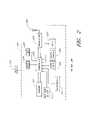
- FIG. 2is a block diagram of a sensor unit.
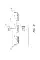
- FIG. 3is a block diagram of a repeater unit.
- FIG. 4is a block diagram of the base unit.
- FIG. 5shows a network communication packet used by the sensor units, repeater units, and the base unit.
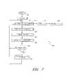
- FIG. 6is a flowchart showing operation of a sensor unit that provides relatively continuous monitoring.
- FIG. 7is a flowchart showing operation of a sensor unit that provides periodic monitoring.
- FIG. 8shows how the sensor system can be used to detect water leaks.
- FIG. 1shows a sensor system 100 that includes a plurality of sensor units 102 - 106 that communicate with a base unit 112 through a number of repeater units 110 - 111 .
- the sensor units 102 - 106are located throughout a building 101 .
- Sensor units 102 - 104communicate with the repeater 110 .
- Sensor units 105 - 106communicate with the repeater 111 .
- the repeaters 110 - 111communicate with the base unit 112 .
- the base unit 112communicates with a monitoring computer system 113 through a computer network connection such as, for example, Ethernet, wireless Ethernet, firewire port, Universal Serial Bus (USB) port, bluetooth, etc.
- USBUniversal Serial Bus
- the computer system 113contacts a building manager, maintenance service, alarm service, or other responsible personnel 120 using one or more of several communication systems such as, for example, telephone 121 , pager 122 , cellular telephone 123 (e.g., direct contact, voicemail, text, etc.), and/or through the Internet and/or local area network 124 (e.g., through email, instant messaging, network communications, etc.).
- multiple base units 112are provided to the monitoring computer 113 .
- the monitoring computer 113is provided to more than one computer monitors, thus, allowing more data to be displayed than can conveniently be displayed on a single monitor.
- the monitoring computer 113is provided to multiple monitors located in different locations, thus allowing the data from the monitoring computer 113 to be displayed in multiple locations.
- the sensor units 102 - 106include sensors to measure conditions, such as, for example, smoke, temperature, moisture, water, water temperature, humidity, carbon monoxide, natural gas, propane gas, security alarms, intrusion alarms (e.g., open doors, broken windows, open windows, and the like), other flammable gases, radon, poison gasses, etc.
- Different sensor unitscan be configured with different sensors or with combinations of sensors.
- the sensor units 102 and 104could be configured with smoke and/or temperature sensors while the sensor unit 103 could be configured with a humidity sensor.
- the discussion that followsgenerally refers to the sensor unit 102 as an example of a sensor unit, with the understanding that the description of the sensor unit 102 can be applied to many sensor units.
- the discussiongenerally refers to the repeater 110 by way of example, and not limitation. It will also be understood by one of ordinary skill in the art that repeaters are useful for extending the range of the sensor units 102 - 106 but are not required in all embodiments. Thus, for example, in one embodiment, one or more of the sensor units 102 - 106 can communicate directly with the base unit 112 without going through a repeater. It will also be understood by one of ordinary skill in the art that FIG.
- FIG. 1shows only five sensor units ( 102 - 106 ) and two repeater units ( 110 - 111 ) for purposes of illustration and not by way of limitation.
- An installation in a large apartment building or complexwould typically involve many sensor units and repeater units.
- one repeater unitcan service relatively many sensor units.
- the sensor units 102can communicate directly with the base unit 112 without going through a repeater 111 .
- the sensor unit 102When the sensor unit 102 detects an anomalous condition (e.g., smoke, fire, water, etc.) the sensor unit communicates with the appropriate repeater unit 110 and provides data regarding the anomalous condition.
- the repeater unit 110forwards the data to the base unit 112 , and the base unit 112 forwards the information to the computer 113 .
- the computer 113evaluates the data and takes appropriate action. If the computer 113 determines that the condition is an emergency (e.g., fire, smoke, large quantities of water), then the computer 113 contacts the appropriate personnel 120 . If the computer 113 determines that a the situation warrants reporting, but is not an emergency, then the computer 113 logs the data for later reporting. In this way, the sensor system 100 can monitor the conditions in and around the building 101 .
- an emergencye.g., fire, smoke, large quantities of water
- the sensor unit 102has an internal power source (e.g., battery, solar cell, fuel cell, etc.). In order to conserve power, the sensor unit 102 is normally placed in a low-power mode. In one embodiment, using sensors that require relatively little power, while in the low-power mode the sensor unit 102 takes regular sensor readings and evaluates the readings to determine if an anomalous condition exists. In one embodiment, using sensors that require relatively more power, while in the low-power mode, the sensor unit 102 takes and evaluates sensor readings at periodic intervals. If an anomalous condition is detected, then the sensor unit 102 “wakes up” and begins communicating with the base unit 112 through the repeater 110 .
- an internal power sourcee.g., battery, solar cell, fuel cell, etc.
- the sensor unit 102also “wakes up” and sends status information (e.g., power levels, self diagnostic information, etc.) to the base unit (or repeater) and then listens for commands for a period of time.
- the sensor unit 102also includes a tamper detector. When tampering with the sensor unit 102 is detected, the sensor unit 102 reports such tampering to the base unit 112 .
- the sensor unit 102provides bi-directional communication and is configured to receive data and/or instructions from the base unit 112 .
- the base unit 112can instruct the sensor unit 102 to perform additional measurements, to go to a standby mode, to wake up, to report battery status, to change wake-up interval, to run self-diagnostics and report results, etc.
- the sensor unit 102reports its general health and status on a regular basis (e.g., results of self-diagnostics, battery health, etc.)
- the sensor unit 102provides two wake-up modes, a first wake-up mode for taking measurements (and reporting such measurements if deemed necessary), and a second wake-up mode for listening for commands from the central reporting station.
- the two wake-up modes, or combinations thereof,can occur at different intervals.
- the sensor unit 102use spread-spectrum techniques to communicate with the repeater unit 110 . In one embodiment, the sensor unit 102 use frequency-hopping spread-spectrum. In one embodiment, the sensor unit 102 has an address or identification (ID) code that distinguishes the sensor unit 102 from the other sensor units. The sensor unit 102 attaches its ID to outgoing communication packets so that transmissions from the sensor unit 102 can be identified by the repeater 110 . The repeater 110 attaches the ID of the sensor unit 102 to data and/or instructions that are transmitted to the sensor unit 102 . In one embodiment, the sensor unit 102 ignores data and/or instructions that are addressed to other sensor units.
- IDaddress or identification
- the sensor unit 102includes a reset function.
- the reset functionis activated by the reset switch 208 .
- the reset functionis active for a prescribed interval of time.
- the transceiver 203is in a receiving mode and can receive the identification code from an external programmer.
- the external programmerwirelessly transmits a desired identification code.
- the identification codeis programmed by an external programmer that is connected to the sensor unit 102 through an electrical connector.
- the electrical connection to the sensor unit 102is provided by sending modulated control signals (power line carrier signals) through a connector used to connect the power source 206 .
- the external programmerprovides power and control signals.
- the external programmeralso programs the type of sensor(s) installed in the sensor unit.
- the identification codeincludes an area code (e.g., apartment number, zone number, floor number, etc.) and a unit number (e.g., unit 1, 2, 3, etc.).
- the senorcommunicates with the repeater on the 900 MHz band. This band provides good transmission through walls and other obstacles normally found in and around a building structure. In one embodiment, the sensor communicates with the repeater on bands above and/or below the 900 MHz band. In one embodiment, the sensor, repeater, and/or base unit listens to a radio frequency channel before transmitting on that channel or before beginning transmission. If the channel is in use, (e.g., by another device such as another repeater, a cordless telephone, etc.) then the sensor, repeater, and/or base unit changes to a different channel.
- the senor, repeater, and/or base unitcoordinate frequency hopping by listening to radio frequency channels for interference and using an algorithm to select a next channel for transmission that avoids the interference.
- the sensorwill test (e.g., listen to) the channel before transmission to avoid channels that are blocked, in use, or jammed.
- the sensorcontinues to transmit data until it receives an acknowledgement from the base unit that the message has been received.
- the sensortransmits data having a normal priority (e.g., status information) and does not look for an acknowledgement, and the sensor transmits data having elevated priority (e.g., excess smoke, temperature, etc.) until an acknowledgement is received.
- a normal prioritye.g., status information
- elevated prioritye.g., excess smoke, temperature, etc.
- the repeater unit 110is configured to relay communications traffic between the sensor 102 (and similarly, the sensor units 103 - 104 ) and the base unit 112 .
- the repeater unit 110typically operates in an environment with several other repeater units (such as the repeater unit 111 in FIG. 1 ) and thus, the repeater unit 110 contains a database (e.g., a lookup table) of sensor unit IDs.
- the repeater 110has database entries for the Ids of the sensors 102 - 104 , and thus, the sensor 110 will only communicate with sensor units 102 - 104 .
- the repeater 110has an internal power source (e.g., battery, solar cell, fuel cell, etc.) and conserves power by maintaining an internal schedule of when the sensor units 102 - 104 are expected to transmit. In one embodiment, the repeater unit 110 goes to a low-power mode when none of its designated sensor units is scheduled to transmit. In one embodiment, the repeater 110 uses spread-spectrum techniques to communicate with the base unit 112 and with the sensor units 102 - 104 . In one embodiment, the repeater 110 uses frequency-hopping spread-spectrum to communicate with the base unit 112 and the sensor units 102 - 104 .
- an internal power sourcee.g., battery, solar cell, fuel cell, etc.
- the repeater unit 110has an address or identification (ID) code and the repeater unit 110 attaches its address to outgoing communication packets that originate in the repeater (that is, packets that are not being forwarded). In one embodiment, the repeater unit 110 ignores data and/or instructions that are addressed to other repeater units or to sensor units not serviced by the repeater 110 .
- IDaddress or identification
- the base unit 112communicates with the sensor unit 102 by transmitting a communication packet addressed to the sensor unit 102 .
- the repeaters 110 and 111both receive the communication packet addressed to the sensor unit 102 .
- the repeater unit 111ignores the communication packet addressed to the sensor unit 102 .
- the repeater unit 110transmits the communication packet addressed to the sensor unit 102 to the sensor unit 102 .
- the sensor unit 102 , the repeater unit 110 , and the base unit 112communicate using Frequency-Hopping Spread Spectrum (FHSS), also known as channel-hopping.
- FHSSFrequency-Hopping Spread Spectrum
- Frequency-hopping wireless systemsoffer the advantage of avoiding other interfering signals and avoiding collisions. Moreover, there are regulatory advantages given to systems that do not transmit continuously at one frequency. Channel-hopping transmitters change frequencies after a period of continuous transmission, or when interference is encountered. These systems may have higher transmit power and relaxed limitations on in-band spurs. FCC regulations limit transmission time on one channel to 400 milliseconds (averaged over 10-20 seconds depending on channel bandwidth) before the transmitter must change frequency. There is a minimum frequency step when changing channels to resume transmission. If there are 25 to 49 frequency channels, regulations allow effective radiated power of 24 dBm, spurs must be ⁇ 20 dBc, and harmonics must be ⁇ 41.2 dBc. With 50 or more channels, regulations allow effective radiated power to be up to 30 dBm.
- the sensor unit 102 , the repeater unit 110 , and the base unit 112communicate using FHSS wherein the frequency hopping of the sensor unit 102 , the repeater unit 110 , and the base unit 112 are not synchronized such that at any given moment, the sensor unit 102 and the repeater unit 110 are on different channels.
- the base unit 112communicates with the sensor unit 102 using the hop frequencies synchronized to the repeater unit 110 rather than the sensor unit 102 .
- the repeater unit 110then forwards the data to the sensor unit using hop frequencies synchronized to the sensor unit 102 .
- Such a systemlargely avoids collisions between the transmissions by the base unit 112 and the repeater unit 110 .
- the sensor units 102 - 106all use FHSS and the sensor units 102 - 106 are not synchronized. Thus, at any given moment, it is unlikely that any two or more of the sensor units 102 - 106 will transmit on the same frequency. In this manner, collisions are largely avoided. In one embodiment, collisions are not detected but are tolerated by the system 100 . If a collisions does occur, data lost due to the collision is effectively re-transmitted the next time the sensor units transmit sensor data. When the sensor units 102 - 106 and repeater units 110 - 111 operate in asynchronous mode, then a second collision is highly unlikely because the units causing the collisions have hopped to different channels.
- the sensor units 102 - 106 , repeater units 110 - 110 , and the base unit 112use the same hop rate. In one embodiment, the sensor units 102 - 106 , repeater units 110 - 111 , and the base unit 112 use the same pseudo-random algorithm to control channel hopping, but with different starting seeds. In one embodiment, the starting seed for the hop algorithm is calculated from the ID of the sensor units 102 - 106 , repeater units 110 - 111 , or the base unit 112 .
- the base unitcommunicates with the sensor unit 102 by sending a communication packet addressed to the repeater unit 110 , where the packet sent to the repeater unit 110 includes the address of the sensor unit 102 .
- the repeater unit 102extracts the address of the sensor unit 102 from the packet and creates and transmits a packet addressed to the sensor unit 102 .
- the repeater unit 110is configured to provide bi-directional communication between its sensors and the base unit 112 .
- the repeater 110is configured to receive instructions from the base unit 110 .
- the base unit 112can instruct the repeater to: send commands to one or more sensors; go to standby mode; “wake up”; report battery status; change wake-up interval; run self-diagnostics and report results; etc.
- the base unit 112is configured to receive measured sensor data from a number of sensor units either directly, or through the repeaters 110 - 111 .
- the base unit 112also sends commands to the repeater units 110 - 111 and/or to the sensor units 102 - 106 .
- the base unit 112communicates with a diskless computer 113 that runs off of a CD-ROM.
- the base unit 112receives data from a sensor unit 102 - 106 indicating that there may be an emergency condition (e.g., a fire or excess smoke, temperature, water, etc.) the computer 113 will attempt to notify the responsible party 120 .
- an emergency conditione.g., a fire or excess smoke, temperature, water, etc.
- the computer 112maintains a database of the health, power status (e.g., battery charge), and current operating status of all of the sensor units 102 - 106 and the repeater units 110 - 111 .
- the computer 113automatically performs routine maintenance by sending commands to each sensor unit 102 - 106 to run a self-diagnostic and report the results. The computer 113 collects and logs such diagnostic results.
- the computer 113sends instructions to each sensor unit 102 - 106 telling the sensor how long to wait between “wakeup” intervals.
- the computer 113schedules different wakeup intervals to different sensor unit 102 - 106 based on the sensor unit's health, power status, location, etc.
- the computer 113schedules different wakeup intervals to different sensor unit 102 - 106 based on the type of data and urgency of the data collected by the sensor unit (e.g., sensor units that have smoke and/or temperature sensors produce data that should be checked relatively more often than sensor units that have humidity or moisture sensors).
- the base unitsends instructions to repeaters to route sensor information around a failed repeater.
- the computer 113produces a display that tells maintenance personnel which sensor units 102 - 106 need repair or maintenance. In one embodiment, the computer 113 maintains a list showing the status and/or location of each sensor according to the ID of each sensor.
- the sensor units 102 - 106 and/or the repeater units 110 - 111measure the signal strength of the wireless signals received (e.g., the sensor unit 102 measures the signal strength of the signals received from the repeater unit 110 , the repeater unit 110 measures the signal strength received from the sensor unit 102 and/or the base unit 112 ).
- the sensor units 102 - 106 and/or the repeater units 110 - 111report such signal strength measurement back to the computer 113 .
- the computer 113evaluates the signal strength measurements to ascertain the health and robustness of the sensor system 100 .
- the computer 113uses the signal strength information to re-route wireless communications traffic in the sensor system 100 .
- the computer 113can send instructions to the repeater unit 111 to add the ID of the sensor unit 102 to the database of the repeater unit 111 (and similarly, send instructions to the repeater unit 110 to remove the ID of the sensor unit 102 ), thereby routing the traffic for the sensor unit 102 through the router unit 111 instead of the router unit 110 .
- FIG. 2is a block diagram of the sensor unit 102 .
- the sensor unit 102one or more sensors 201 and a transceiver 203 are provided to a controller 202 .
- the controller 202typically provides power, data, and control information to the sensor(s) 201 and the transceiver 202 .
- a power source 206is provided to the controller 202 .
- An optional tamper sensor 205is also provided to the controller 202 .
- a reset device (e.g., a switch) 208is proved to the controller 202 .
- an optional audio output device 209is provided.
- the sensor 201is configured as a plug-in module that can be replaced relatively easily.
- a temperature sensor 220is provided to the controller 202 . In one embodiment, the temperature sensor 220 is configured to measure ambient temperature.
- the transceiver 203is based on a TRF 6901 transceiver chip from Texas Instruments. Inc.
- the controller 202is a conventional programmable microcontroller.
- the controller 202is based on a Field Programmable Gate Array (FPGA), such as, for example, provided by Xilinx Corp.
- the sensor 201includes an optoelectric smoke sensor with a smoke chamber.
- the sensor 201includes a thermistor.
- the sensor 201includes a humidity sensor.
- the sensor 201includes a sensor, such as, for example, a water level sensor, a water temperature sensor, a carbon monoxide sensor, a moisture sensor, a water flow sensor, natural gas sensor, propane sensor, etc.
- the controller 202receives sensor data from the sensor(s) 201 . Some sensors 201 produce digital data. However, for many types of sensors 201 , the sensor data is analog data. Analog sensor data is converted to digital format by the controller 202 . In one embodiment, the controller evaluates the data received from the sensor(s) 201 and determines whether the data is to be transmitted to the base unit 112 . The sensor unit 102 generally conserves power by not transmitting data that falls within a normal range. In one embodiment, the controller 202 evaluates the sensor data by comparing the data value to a threshold value (e.g., a high threshold, a low threshold, or a high-low threshold).
- a threshold valuee.g., a high threshold, a low threshold, or a high-low threshold
- the data thresholdis programmed into the controller 202 .
- the data thresholdis programmed by the base unit 112 by sending instructions to the controller 202 .
- the controller 202obtains sensor data and transmits the data when commanded by the computer 113 .
- the tamper sensor 205is configured as a switch that detects removal of/or tampering with the sensor unit 102 .
- FIG. 3is a block diagram of the repeater unit 110 .
- a first transceiver 302 and a second transceiver 304are provided to a controller 303 .
- the controller 303typically provides power, data, and control information to the transceivers 302 , 304 .
- a power source 306is provided to the controller 303 .
- An optional tamper sensor(not shown) is also provided to the controller 303 .
- the controller 303When relaying sensor data to the base unit 112 , the controller 303 receives data from the first transceiver 302 and provides the data to the second transceiver 304 . When relaying instructions from the base unit 112 to a sensor unit, the controller 303 receives data from the second transceiver 304 and provides the data to the first transceiver 302 . In one embodiment, the controller 303 conserves power by powering-down the transceivers 302 , 304 during periods when the controller 303 is not expecting data. The controller 303 also monitors the power source 306 and provides status information, such as, for example, self-diagnostic information and/or information about the health of the power source 306 , to the base unit 112 .
- status informationsuch as, for example, self-diagnostic information and/or information about the health of the power source 306
- the controller 303sends status information to the base unit 112 at regular intervals. In one embodiment, the controller 303 sends status information to the base unit 112 when requested by the base unit 112 . In one embodiment, the controller 303 sends status information to the base unit 112 when a fault condition (e.g., battery low) is detected.
- a fault conditione.g., battery low
- the controller 303includes a table or list of identification codes for wireless sensor units 102 .
- the repeater 303forwards packets received from, or sent to, sensor units 102 in the list.
- the repeater 110receives entries for the list of sensor units from the computer 113 .
- the controller 303determines when a transmission is expected from the sensor units 102 in the table of sensor units and places the repeater 110 (e.g., the transceivers 302 , 304 ) in a low-power mode when no transmissions are expected from the transceivers on the list.
- the controller 303recalculates the times for low-power operation when a command to change reporting interval is forwarded to one of the sensor units 102 in the list (table) of sensor units or when a new sensor unit is added to the list (table) of sensor units.
- FIG. 4is a block diagram of the base unit 112 .
- a transceiver 402 and a computer interface 404are provided to a controller 403 .
- the controller 303typically provides data and control information to the transceivers 402 and to the interface.
- the interface 404is provided to a port on the monitoring computer 113 .
- the interface 404can be a standard computer data interface, such as, for example, Ethernet, wireless Ethernet, firewire port, Universal Serial Bus (USB) port, bluetooth, etc.
- USBUniversal Serial Bus
- FIG. 5shows a communication packet 500 used by the sensor units, repeater units, and the base unit.
- the packet 500includes a preamble portion 501 , an address (or ID) portion 502 , a data payload portion 503 , and an integrity portion 504 .
- the integrity portion 504includes a checksum.
- the sensor units 102 - 106 , the repeater units 110 - 111 , and the base unit 112communicate using packets such as the packet 500 .
- the packets 500are transmitted using FHSS.
- the data packets that travel between the sensor unit 102 , the repeater unit 111 , and the base unit 112are encrypted. In one embodiment, the data packets that travel between the sensor unit 102 , the repeater unit 111 , and the base unit 112 are encrypted and an authentication code is provided in the data packet so that the sensor unit 102 , the repeater unit, and/or the base unit 112 can verify the authenticity of the packet.
- the address portion 502includes a first code and a second code.
- the repeater 111only examines the first code to determine if the packet should be forwarded.
- the first codecan be interpreted as a building (or building complex) code and the second code interpreted as a subcode (e.g., an apartment code, area code, etc.).
- a repeater that uses the first code for forwardingthus, forwards packets having a specified first code (e.g., corresponding to the repeater's building or building complex).
- a specified first codee.g., corresponding to the repeater's building or building complex.
- a repeater so configuredonly needs to know the first code to forward packets for any repeater in the building or building complex. This does, however, raise the possibility that two repeaters in the same building could try to forward packets for the same sensor unit 102 .
- each repeaterwaits for a programmed delay period before forwarding a packet. Thus, reducing the chance of packet collisions at the base unit (in the case of sensor unit to base unit packets) and reducing the chance of packet collisions at the sensor unit (in the case of base unit to sensor unit packets).
- a delay periodis programmed into each repeater. In one embodiment, delay periods are pre-programmed onto the repeater units at the factory or during installation.
- a delay periodis programmed into each repeater by the base unit 112 .
- a repeaterrandomly chooses a delay period.
- a repeaterrandomly chooses a delay period for each forwarded packet.
- the first codeis at least 6 digits.
- the second codeis at least 5 digits.
- the first code and the second codeare programmed into each sensor unit at the factory. In one embodiment, the first code and the second code are programmed when the sensor unit is installed. In one embodiment, the base unit 112 can re-program the first code and/or the second code in a sensor unit.
- collisionsare further avoided by configuring each repeater unit 111 to begin transmission on a different frequency channel.
- each repeater unit 111configuring each repeater unit 111 to begin transmission on a different frequency channel.
- FIG. 6is a flowchart showing one embodiment of the operation of the sensor unit 102 wherein relatively continuous monitoring is provided.
- a power up block 601is followed by an initialization block 602 .
- the sensor unit 102checks for a fault condition (e.g., activation of the tamper sensor, low battery, internal fault, etc.) in a block 603 .
- a decision block 604checks the fault status. If a fault has occurred, then the process advances to a block 605 were the fault information is transmitted to the repeater 110 (after which, the process advances to a block 612 ); otherwise, the process advances to a block 606 .
- the sensor unit 102takes a sensor reading from the sensor(s) 201 .
- the sensor datais subsequently evaluated in a block 607 . If the sensor data is abnormal, then the process advances to a transmit block 609 where the sensor data is transmitted to the repeater 110 (after which, the process advances to a block 612 ); otherwise, the process advances to a timeout decision block 610 . If the timeout period has not elapsed, then the process returns to the fault-check block 603 ; otherwise, the process advances to a transmit status block 611 where normal status information is transmitted to the repeater 110 .
- the normal status information transmittedis analogous to a simple “ping” which indicates that the sensor unit 102 is functioning normally.
- transceiver 203is normally powered down.
- the controller 202powers up the transceiver 203 during execution of the blocks 605 , 609 , 611 , and 612 .
- the monitoring computer 113can send instructions to the sensor unit 102 to change the parameters used to evaluate data used in block 607 , the listen period used in block 612 , etc.
- FIG. 7is a flowchart showing one embodiment of operation of the sensor unit 102 wherein periodic monitoring is provided.
- a power up block 701is followed by an initialization block 702 . After initialization, the sensor unit 102 enters a low-power sleep mode.
- the processenters a wake-up block 704 followed by a transmit fault block 705 . If no fault occurs during the sleep period, then when the specified sleep period has expired, the process enters a block 706 where the sensor unit 102 takes a sensor reading from the sensor(s) 201 . The sensor data is subsequently sent to the monitoring computer 113 in a report block 707 . After reporting, the sensor unit 102 enters a listen block 708 where the sensor unit 102 listens for a relatively short period of time for instructions from monitoring computer 708 . If an instruction is received, then the sensor unit 102 performs the instructions, otherwise, the process returns to the sleep block 703 .
- a faultoccurs during the sleep mode (e.g., the tamper sensor is activated)
- the processenters a wake-up block 704 followed by a transmit fault block 705 . If no fault occurs during the sleep period, then when the specified sleep period has expired, the process enters a block 706 where the sensor unit 102 takes a sensor reading from
- the senor 201 and transceiver 203are normally powered down.
- the controller 202powers up the sensor 201 during execution of the block 706 .
- the controller 202powers up the transceiver during execution of the blocks 705 , 707 , and 708 .
- the monitoring computer 113can send instructions to the sensor unit 102 to change the sleep period used in block 703 , the listen period used in block 708 , etc.
- the sensor unittransmits sensor data until a handshaking-type acknowledgement is received.
- the sensor unit 102retransmits its data and waits for an acknowledgement.
- the sensor unit 102continues to transmit data and wait for an acknowledgement until an acknowledgement is received.
- the sensor unitaccepts an acknowledgement from a repeater unit 111 and it then becomes the responsibility of the repeater unit 111 to make sure that the data is forwarded to the base unit 112 .
- the repeater unit 111does not generate the acknowledgement, but rather forwards an acknowledgement from the base unit 112 to the sensor unit 102 .
- the two-way communication ability of the sensor unit 102provides the capability for the base unit 112 to control the operation of the sensor unit 102 and also provides the capability for robust handshaking-type communication between the sensor unit 102 and the base unit 112 .
- the monitoring computer 113can instruct the sensor unit 102 to operate in a relatively continuous mode where the sensor repeatedly takes sensor readings and transmits the readings to the monitoring computer 113 .
- a relatively continuous modewhere the sensor repeatedly takes sensor readings and transmits the readings to the monitoring computer 113 .
- Such a modewould can be used, for example, when the sensor unit 102 (or a nearby sensor unit) has detected a potentially dangerous condition (e.g., smoke, rapid temperature rise, etc.)
- FIG. 8shows the sensor system used to detect water leaks.
- the sensor unit 102includes a water level sensor and 803 and/or a water temperature sensor 804 .
- the water level sensor 803 and/or water temperature sensor 804are place, for example, in a tray underneath a water heater 801 in order to detect leaks from the water heater 801 and thereby prevent water damage from a leaking water heater.
- an temperature sensoris also provide to measure temperature near the water heater.
- the water level sensorcan also be placed under a sink, in a floor sump, etc.
- the severity of a leakis ascertained by the sensor unit 102 (or the monitoring computer 113 ) by measuring the rate of rise in the water level.
- the severity of a leakcan also be ascertained at least in part by measuring the temperature of the water.
- a first water flow sensoris placed in an input water line for the hot water tank 801 and a second water flow sensor is placed in an output water line for the hot water tank. Leaks in the tank can be detected by observing a difference between the water flowing through the two sensors.
- a remote shutoff valve 810is provided, so that the monitoring system 100 can shutoff the water supply to the water heater when a leak is detected.
- the shutoff valveis controlled by the sensor unit 102 .
- the sensor unit 102receives instructions from the base unit 112 to shut off the water supply to the heater 801 .
- the responsible party 120sends instructions to the monitoring computer 113 instructing the monitoring computer 113 to send water shut off instructions to the sensor unit 102 .
- the sensor unit 102controls a gas shutoff valve 811 to shut off the gas supply to the water heater 801 and/or to a furnace (not shown) when dangerous conditions (such as, for example, gas leaks, carbon monoxide, etc.) are detected.
- a gas detector 812is provided to the sensor unit 102 .
- the gas detector 812measures carbon monoxide.
- the gas detector 812measures flammable gas, such as, for example, natural gas or propane.
- an optional temperature sensor 818is provided to measure stack temperature. Using data from the temperature sensor 818 , the sensor unit 102 reports conditions, such as, for example, excess stack temperature. Excess stack temperature is often indicative of poor heat transfer (and thus poor efficiency) in the water heater 818 .
- an optional temperature sensor 819is provided to measure temperature of water in the water heater 810 . Using data from the temperature sensor 819 , the sensor unit 102 reports conditions, such as, for example, over-temperature or under-temperature of the water in the water heater.
- an optional current probe 821is provided to measure electric current provided to a heating element 820 in an electric water heater.
- the sensor unit 102uses data from the current probe 821 to report conditions, such as, for example, no current (indicating a burned-out heating element 820 ).
- An over-current conditionoften indicates that the heating element 820 is encrusted with mineral deposits and needs to be replaced or cleaned.
- the monitoring systemcan measure the amount of energy provided to the water heater and thus the cost of hot water, and the efficiency of the water heater.
- the senor 803includes a moisture sensor. Using data from the moisture sensor, the sensor unit 102 reports moisture conditions, such as, for example, excess moisture that would indicate a water leak, excess condensation, etc.
- the sensor unit 102is provided to a moisture sensor (such as the sensor 803 ) located near an air conditioning unit. Using data from the moisture sensor, the sensor unit 102 reports moisture conditions, such as, for example, excess moisture that would indicate a water leak, excess condensation, etc.
- the senor 201includes a moisture sensor.
- the moisture sensorcan be place under a sink or a toilet (to detect plumbing leaks) or in an attic space (to detect roof leaks).
- the sensor 201includes a humidity sensor.
- the humidity sensorcan be place under a sink, in an attic space, etc. to detect excess humidity (due to leaks, condensation, etc.).
- the monitoring computer 113compares humidity measurements taken from different sensor units in order to detect areas that have excess humidity. Thus, for example, the monitoring computer 113 can compare the humidity readings from a first sensor unit 102 in a first attic area, to a humidity reading from a second sensor unit 102 in a second area.
- the monitoring computercan take humidity readings from a number of attic areas to establish a baseline humidity reading and then compare the specific humidity readings from various sensor units to determine if one or more of the units are measuring excess humidity.
- the monitoring computer 113would flag areas of excess humidity for further investigation by maintenance personnel.
- the monitoring computer 113maintains a history of humidity readings for various sensor units and flags areas that show an unexpected increase in humidity for investigation by maintenance personnel.
- the monitoring system 100detects conditions favorable for fungus (e.g., mold, mildew, fungus, etc.) growth by using a first humidity sensor located in a first building area to produce first humidity data and a second humidity sensor located in a second building area to produce second humidity data.
- the building areascan be, for example, areas near a sink drain, plumbing fixture, plumbing, attic areas, outer walls, a bilge area in a boat, etc.
- the monitoring station 113collects humidity readings from the first humidity sensor and the second humidity sensor and indicates conditions favorable for fungus growth by comparing the first humidity data and the second humidity data. In one embodiment, the monitoring station 113 establishes a baseline humidity by comparing humidity readings from a plurality of humidity sensors and indicates possible fungus growth conditions in the first building area when at least a portion of the first humidity data exceeds the baseline humidity by a specified amount. In one embodiment, the monitoring station 113 establishes a baseline humidity by comparing humidity readings from a plurality of humidity sensors and indicates possible fungus growth conditions in the first building area when at least a portion of the first humidity data exceeds the baseline humidity by a specified percentage.
- the monitoring station 113establishes a baseline humidity history by comparing humidity readings from a plurality of humidity sensors and indicates possible fungus growth conditions in the first building area when at least a portion of the first humidity data exceeds the baseline humidity history by a specified amount over a specified period of time. In one embodiment, the monitoring station 113 establishes a baseline humidity history by comparing humidity readings from a plurality of humidity sensors over a period of time and indicates possible fungus growth conditions in the first building area when at least a portion of the first humidity data exceeds the baseline humidity by a specified percentage of a specified period of time.
- the sensor unit 102transmits humidity data when it determines that the humidity data fails a threshold test.
- the humidity threshold for the threshold testis provided to the sensor unit 102 by the monitoring station 113 .
- the humidity threshold for the threshold testis computed by the monitoring station from a baseline humidity established in the monitoring station.
- the baseline humidityis computed at least in part as an average of humidity readings from a number of humidity sensors.
- the baseline humidityis computed at least in part as a time average of humidity readings from a number of humidity sensors.
- the baseline humidityis computed at least in part as a time average of humidity readings from a humidity sensor.
- the baseline humidityis computed at least in part as the lesser of a maximum humidity reading an average of a number of humidity readings.
- the sensor unit 102reports humidity readings in response to a query by the monitoring station 113 . In one embodiment, the sensor unit 102 reports humidity readings at regular intervals. In one embodiment, a humidity interval is provided to the sensor unit 102 by the monitoring station 113 .
- the calculation of conditions for fungus growthis comparing humidity readings from one or more humidity sensors to the baseline (or reference) humidity. In one embodiment, the comparison is based on comparing the humidity readings to a percentage (e.g., typically a percentage greater than 100%) of the baseline value. In one embodiment, the comparison is based on comparing the humidity readings to a specified delta value above the reference humidity. In one embodiment, the calculation of likelihood of conditions for fungus growth is based on a time history of humidity readings, such that the longer the favorable conditions exist, the greater the likelihood of fungus growth. In one embodiment, relatively high humidity readings over a period of time indicate a higher likelihood of fungus growth than relatively high humidity readings for short periods of time.
- a relatively sudden increase in humidity as compared to a baseline or reference humidityis reported by the monitoring station 113 as a possibility of a water leak. If the relatively high humidity reading continues over time then the relatively high humidity is reported by the monitoring station 113 as possibly being a water leak and/or an area likely to have fungus growth or water damage.
- Temperatures relatively more favorable to fungus growthincrease the likelihood of fungus growth.
- temperature measurements from the building areasare also used in the fungus grown-likelihood calculations.
- a threshold value for likelihood of fungus growthis computed at least in part as a function of temperature, such that temperatures relatively more favorable to fungus growth result in a relatively lower threshold than temperatures relatively less favorable for fungus growth.
- the calculation of a likelihood of fungus growthdepends at least in part on temperature such that temperatures relatively more favorable to fungus growth indicate a relatively higher likelihood of fungus growth than temperatures relatively less favorable for fungus growth.
- a maximum humidity and/or minimum threshold above a reference humidityis relatively lower for temperature more favorable to fungus growth than the maximum humidity and/or minimum threshold above a reference humidity for temperatures relatively less favorable to fungus growth.
- a water flow sensoris provided to the sensor unit 102 .
- the sensor unit 102obtains water flow data from the water flow sensor and provides the water flow data to the monitoring computer 113 .
- the monitoring computer 113can then calculate water usage. Additionally, the monitoring computer can watch for water leaks, by, for example, looking for water flow when there should be little or no flow. Thus, for example, if the monitoring computer detects water usage throughout the night, the monitoring computer can raise an alert indicating that a possible water leak has occurred.
- the sensor 201includes a water flow sensor is provided to the sensor unit 102 .
- the sensor unit 102obtains water flow data from the water flow sensor and provides the water flow data to the monitoring computer 113 .
- the monitoring computer 113can then calculate water usage. Additionally, the monitoring computer can watch for water leaks, by, for example, looking for water flow when there should be little or no flow. Thus, for example, if the monitoring computer detects water usage throughout the night, the monitoring computer can raise an alert indicating that a possible water leak has occurred.
- the sensor 201includes a fire-extinguisher tamper sensor is provided to the sensor unit 102 .
- the fire-extinguisher tamper sensorreports tampering with or use of a fire-extinguisher.
- the fire-extinguisher temper sensorreports that the fire extinguisher has been removed from its mounting, that a fire extinguisher compartment has been opened, and/or that a safety lock on the fire extinguisher has been removed.
- the sensor unit 102is configured as an adjustable-threshold sensor that computes a threshold level.
- the thresholdis computed as an average of a number of sensor measurements.
- the average valueis a relatively long-term average.
- the averageis a time-weighted average wherein recent sensor readings used in the averaging process are weighted differently than less recent sensor readings. In one embodiment, more recent sensor readings are weighted relatively more heavily than less recent sensor readings. In one embodiment, more recent sensor readings are weighted relatively less heavily than less recent sensor readings.
- the averageis used to set the threshold level. When the sensor readings rise above the threshold level, the sensor indicates a notice condition.
- the senorindicates a notice condition when the sensor reading rises above the threshold value for a specified period of time. In one embodiment, the sensor indicates a notice condition when a statistical number of sensor readings (e.g., 3 of 2, 5 of 3, 10 of 7, etc.) are above the threshold level. In one embodiment, the sensor unit 102 indicates various levels of alarm (e.g., warning, alert, alarm) based on how far above the threshold the sensor reading has risen.
- a statistical number of sensor readingse.g., 3 of 2, 5 of 3, 10 of 7, etc.
- the sensor unit 102indicates various levels of alarm (e.g., warning, alert, alarm) based on how far above the threshold the sensor reading has risen.
- the sensor unit 102computes the notice level according to how far the sensor readings have risen above the threshold and how rapidly the sensor readings have risen.
- the level of readings and the rate of risecan be quantified as low, medium, and high.
- the combination of sensor reading level and rate of risethen can be show as a table, as show in Table 1.
- Table 1provides examples and is provided by way of explanation, not limitation.
- the sensor reading v and/or the rate of rise rare lowpass filtered in order to reduce the effects of noise in the sensor readings.
- the thresholdis computed by lowpass filtering the sensor readings v using a filter with a relatively low cutoff frequency. A filter with a relatively low cutoff frequency produces a relatively long-term averaging effect.
- separate thresholdsare computed for the sensor reading and for the rate of rise.
- a calibration procedure periodis provided when the sensor unit 102 is powered up. During the calibration period, the sensor data values from the sensor 201 are used to compute the threshold value, but the sensor does not compute notices, warnings, alarms, etc., until the calibration period is complete. In one embodiment, the sensor unit 102 uses a fixed (e.g., pre-programmed) threshold value to compute notices, warnings, and alarms during the calibration period and then uses the adjustable threshold value once the calibration period has ended.
- a fixed threshold valuee.g., pre-programmed
- the sensor unit 102determines that a failure of the sensor 201 has occurred when the adjustable threshold value exceeds a maximum adjustable threshold value. In one embodiment, the sensor unit 102 determines that a failure of the sensor 201 has occurred when the adjustable threshold value falls below a minimum adjustable threshold value. The sensor unit 102 can report such failure of the sensor 201 to the base unit 112 .
- the sensor unit 102obtains a number of sensor data readings from the sensor 201 and computes the threshold value as a weighted average using a weight vector.
- the weight vectorweights some sensor data readings relatively more than other sensor data readings.
- the sensor unit 102obtains a number of sensor data readings from the sensor unit 201 and filters the sensor data readings and calculates the threshold value from the filtered sensor data readings. In one embodiment, the sensor unit applies a lowpass filter. In one embodiment, the sensor unit 201 uses a Kalman filter to remove unwanted components from the sensor data readings. In one embodiment, the sensor unit 201 discards sensor data readings that are “outliers” (e.g., too far above or too far below a normative value). In this manner, the sensor unit 102 can compute the threshold value even in the presence of noisy sensor data.
- outlierse.g., too far above or too far below a normative value
- the sensor unit 102indicates a notice condition (e.g., alert, warning, alarm) when the threshold value changes too rapidly. In one embodiment, the sensor unit 102 indicates a notice condition (e.g., alert, warning, alarm) when the threshold value exceeds a specified maximum value. In one embodiment, the sensor unit 102 indicates a notice condition (e.g., alert, warning, alarm) when the threshold value falls below a specified minimum value.
- a notice conditione.g., alert, warning, alarm
- the sensor unit 102adjusts one or more operating parameters of the sensor 201 according the threshold value.
- the sensor unit 201can reduce the power used to drive the LED in the optical smoke sensor when the threshold value indicates that the optical smoke sensor can be operated at lower power (e.g., low ambient light conditions, clean sensor, low air particulate conditions, etc.).
- the sensor unit 201can increase the power used to drive the LED when the threshold value indicates that the optical smoke sensor should be operated at higher power (e.g., high ambient light, dirty sensor, higher particulates in the air, etc.).
- an output from a Heating Ventilating and/or Air Conditioning (HVAC) system 350is optionally provided to the sensor unit 102 as shown in FIG. 2 .
- HVACHeating Ventilating and/or Air Conditioning
- an output from the HVAC system 350is optionally provided to the repeater 110 as shown in FIG. 3 and/or to the monitoring system 113 as shown in FIG. 4 .
- the system 100is made aware of the operation of the HVAC system. When the HVAC system turns on or off, the airflow patterns in the room change, and thus the way in which smoke or other materials (e.g., flammable gases, toxic gases, etc.) changes as well.
- the threshold calculationtakes into account the airflow effects caused by the HVAC system.
- an adaptive algorithmis used to allow the sensor unit 102 (or monitoring system 113 ) to “learn” how the HVAC system affects sensor readings and thus the sensor unit 102 (or monitoring system 113 ) can adjust the threshold level accordingly.
- the threshold levelis temporarily changed for a period of time (e.g., raised or lowered) to avoid false alarms when the HVAC system turns on or off. Once the airflow patterns in the room have re-adjusted to the HVAC state, then the threshold level can be re-established for desired system sensitivity.
- the threshold levelis temporarily set to de-sensitize the sensor unit 102 when the HVAC system turns on or off, thus allowing the averaging or lowpass filtering process to establish a new threshold level.
- the sensor unit 102returns to its normal sensitivity based on the new threshold level.
- the senor 201is configured as an infrared sensor. In one embodiment, the sensor 201 is configured as an infrared sensor to measure a temperature of objects within a field of view of the sensor 201 . In one embodiment, the sensor 201 is configured as an infrared sensor. In one embodiment, the sensor 201 is configured as an infrared sensor to detect flames within a field of view of the sensor 201 . In one embodiment, the sensor 201 is configured as an infrared sensor.
- the senor 201is configured as an imaging sensor.
- the controller 202is configured to detect flames by processing of image data from the imaging sensor.
- the wireless systemcan be configured to operate on one or more frequency bands, such as, for example, the HF band, the VHF band, the UHF band, the Microwave band, the Millimeter wave band, etc.
- modulationis not limited to any particular modulation method, such that modulation scheme used can be, for example, frequency modulation, phase modulation, amplitude modulation, combinations thereof, etc.
- modulation scheme usedcan be, for example, frequency modulation, phase modulation, amplitude modulation, combinations thereof, etc.
Landscapes
- Physics & Mathematics (AREA)
- General Physics & Mathematics (AREA)
- Business, Economics & Management (AREA)
- Emergency Management (AREA)
- Engineering & Computer Science (AREA)
- Computer Security & Cryptography (AREA)
- General Health & Medical Sciences (AREA)
- Health & Medical Sciences (AREA)
- Computer Networks & Wireless Communication (AREA)
- Gerontology & Geriatric Medicine (AREA)
- Child & Adolescent Psychology (AREA)
- Alarm Systems (AREA)
- Arrangements For Transmission Of Measured Signals (AREA)
- Telephonic Communication Services (AREA)
- Testing Or Calibration Of Command Recording Devices (AREA)
Abstract
Description
| TABLE 1 |
| Sensor Reading Level (as compared to the threshold) |
| Rate of Rise | High | Warning | Alarm | Alarm | ||
| Medium | Notice | Warning | Alarm | |||
| Low | Notice | Warning | Alarm | |||
| Low | Medium | High | ||||
Claims (33)
Priority Applications (12)
| Application Number | Priority Date | Filing Date | Title |
|---|---|---|---|
| US11/145,880US7336168B2 (en) | 2005-06-06 | 2005-06-06 | System and method for variable threshold sensor |
| CNA2006800201150ACN101194293A (en) | 2005-06-06 | 2006-05-05 | System and method for variable threshold sensor |
| AU2006255737AAU2006255737A1 (en) | 2005-06-06 | 2006-05-05 | System and method for variable threshold sensor |
| EP06752337AEP1889234A1 (en) | 2005-06-06 | 2006-05-05 | System and method for variable threshold sensor |
| RU2007146262/09ARU2007146262A (en) | 2005-06-06 | 2006-05-05 | SYSTEM AND METHOD FOR VARIABLE SENSOR |
| JP2008514663AJP2008546089A (en) | 2005-06-06 | 2006-05-05 | Variable threshold sensor system and method |
| PCT/US2006/017473WO2006132745A1 (en) | 2005-06-06 | 2006-05-05 | System and method for variable threshold sensor |
| KR1020087000163AKR20080019273A (en) | 2005-06-06 | 2006-05-05 | System and method for variable threshold sensors |
| CA002609759ACA2609759A1 (en) | 2005-06-06 | 2006-05-05 | System and method for variable threshold sensor |
| MX2007015264AMX2007015264A (en) | 2005-06-06 | 2006-05-05 | System and method for variable threshold sensor. |
| US12/036,915US20080141754A1 (en) | 2005-06-06 | 2008-02-25 | System and method for variable threshold sensor |
| US12/684,715US20100206039A1 (en) | 2005-06-06 | 2010-01-08 | System and method for variable threshold sensor |
Applications Claiming Priority (1)
| Application Number | Priority Date | Filing Date | Title |
|---|---|---|---|
| US11/145,880US7336168B2 (en) | 2005-06-06 | 2005-06-06 | System and method for variable threshold sensor |
Related Child Applications (2)
| Application Number | Title | Priority Date | Filing Date |
|---|---|---|---|
| US12/036,915ContinuationUS20080141754A1 (en) | 2005-06-06 | 2008-02-25 | System and method for variable threshold sensor |
| US12/036,915Continuation-In-PartUS20080141754A1 (en) | 2005-06-06 | 2008-02-25 | System and method for variable threshold sensor |
Publications (2)
| Publication Number | Publication Date |
|---|---|
| US20060273896A1 US20060273896A1 (en) | 2006-12-07 |
| US7336168B2true US7336168B2 (en) | 2008-02-26 |
Family
ID=37101854
Family Applications (3)
| Application Number | Title | Priority Date | Filing Date |
|---|---|---|---|
| US11/145,880Expired - LifetimeUS7336168B2 (en) | 2005-06-06 | 2005-06-06 | System and method for variable threshold sensor |
| US12/036,915AbandonedUS20080141754A1 (en) | 2005-06-06 | 2008-02-25 | System and method for variable threshold sensor |
| US12/684,715AbandonedUS20100206039A1 (en) | 2005-06-06 | 2010-01-08 | System and method for variable threshold sensor |
Family Applications After (2)
| Application Number | Title | Priority Date | Filing Date |
|---|---|---|---|
| US12/036,915AbandonedUS20080141754A1 (en) | 2005-06-06 | 2008-02-25 | System and method for variable threshold sensor |
| US12/684,715AbandonedUS20100206039A1 (en) | 2005-06-06 | 2010-01-08 | System and method for variable threshold sensor |
Country Status (10)
| Country | Link |
|---|---|
| US (3) | US7336168B2 (en) |
| EP (1) | EP1889234A1 (en) |
| JP (1) | JP2008546089A (en) |
| KR (1) | KR20080019273A (en) |
| CN (1) | CN101194293A (en) |
| AU (1) | AU2006255737A1 (en) |
| CA (1) | CA2609759A1 (en) |
| MX (1) | MX2007015264A (en) |
| RU (1) | RU2007146262A (en) |
| WO (1) | WO2006132745A1 (en) |
Cited By (70)
| Publication number | Priority date | Publication date | Assignee | Title |
|---|---|---|---|---|
| US20060007008A1 (en)* | 2004-05-27 | 2006-01-12 | Lawrence Kates | Method and apparatus for detecting severity of water leaks |
| US20070090945A1 (en)* | 2005-10-20 | 2007-04-26 | Hoogenboom Christopher L | Power conserving mode for a sensor for monitoring the structural integrity of a building |
| US20070139208A1 (en)* | 2005-09-23 | 2007-06-21 | Lawrence Kates | Method and apparatus for detecting moisture in building materials |
| US20070139183A1 (en)* | 2005-12-19 | 2007-06-21 | Lawrence Kates | Portable monitoring unit |
| US20070211076A1 (en)* | 2004-05-27 | 2007-09-13 | Lawrence Kates | Method and apparatus for detecting water leaks |
| US20070229237A1 (en)* | 2005-09-20 | 2007-10-04 | Lawrence Kates | Programmed wireless sensor system |
| US20070234784A1 (en)* | 2004-09-23 | 2007-10-11 | Lawrence Kates | System and method for utility metering and leak detection |
| US20080079572A1 (en)* | 2006-09-28 | 2008-04-03 | Zohar Tsaba | Apparatus and method for using a wireless network as a motion detection system |
| US20080141754A1 (en)* | 2005-06-06 | 2008-06-19 | Lawrence Kates | System and method for variable threshold sensor |
| US20080162085A1 (en)* | 2006-12-29 | 2008-07-03 | Schlumberger Technology Corporation | Method and apparatus for evaluating data associated with an offshore energy platform |
| US20080211678A1 (en)* | 2007-03-02 | 2008-09-04 | Walter Kidde Portable Equipment Inc. | Alarm with CO and smoke sensors |
| US20080212557A1 (en)* | 2007-03-02 | 2008-09-04 | Motorola, Inc. | Method and apparatus for battery-aware dynamic bandwidth allocation for wireless sensor networks |
| US20080278310A1 (en)* | 2004-05-27 | 2008-11-13 | Lawrence Kates | Method of measuring signal strength in a wireless sensor system |
| US20090089818A1 (en)* | 2007-09-27 | 2009-04-02 | James Lester Memmott | Determining the context of a computing device |
| US20090281667A1 (en)* | 2006-07-13 | 2009-11-12 | Mitsubishi Electric Corporation | Air conditioning system |
| US7623028B2 (en) | 2004-05-27 | 2009-11-24 | Lawrence Kates | System and method for high-sensitivity sensor |
| US20100033334A1 (en)* | 2008-08-06 | 2010-02-11 | Luo Ren-Chyuan | Fire detecting system and weight correcting method performed thereby |
| US20100033319A1 (en)* | 2008-08-08 | 2010-02-11 | Pattok Greg R | Notification system and method thereof |
| US20100305761A1 (en)* | 2008-10-11 | 2010-12-02 | Ralph Remsburg | Automatic Mold and Fungus Growth Inhibition System and Method |
| US20110012746A1 (en)* | 2009-07-16 | 2011-01-20 | Fish Jr Richard T | Notification Appliance and Method Thereof |
| US20110215923A1 (en)* | 2010-03-03 | 2011-09-08 | Honeywell International Inc. | Aspirating environmental sensor with webserver and email notification |
| US8134462B1 (en)* | 2008-08-08 | 2012-03-13 | The United States Of America As Represented By The Secretary Of The Navy | Self-contained sensor package for water security and safety |
| US8232884B2 (en) | 2009-04-24 | 2012-07-31 | Gentex Corporation | Carbon monoxide and smoke detectors having distinct alarm indications and a test button that indicates improper operation |
| US8362429B2 (en) | 2007-08-10 | 2013-01-29 | Schlumberger Technology Corporation | Method and apparatus for oil spill detection |
| US8700221B2 (en) | 2010-12-30 | 2014-04-15 | Fluid Handling Llc | Method and apparatus for pump control using varying equivalent system characteristic curve, AKA an adaptive control curve |
| DE102013202100A1 (en)* | 2013-02-08 | 2014-08-14 | Sick Ag | External control module for sensor connected to sensor system, has control unit is designed such that they take an activation signal transmitted to sensor via connection unit in advance specified times or at external request |
| US8964338B2 (en) | 2012-01-11 | 2015-02-24 | Emerson Climate Technologies, Inc. | System and method for compressor motor protection |
| US9121407B2 (en) | 2004-04-27 | 2015-09-01 | Emerson Climate Technologies, Inc. | Compressor diagnostic and protection system and method |
| US9140728B2 (en) | 2007-11-02 | 2015-09-22 | Emerson Climate Technologies, Inc. | Compressor sensor module |
| US20150279184A1 (en)* | 2014-03-27 | 2015-10-01 | Honeywell International Inc. | Alarm system with wireless communication |
| US9162095B2 (en) | 2011-03-09 | 2015-10-20 | Alan E. Thomas | Temperature-based fire detection |
| US9183723B2 (en) | 2012-01-31 | 2015-11-10 | Cleanalert, Llc | Filter clog detection and notification system |
| US9186609B2 (en) | 2012-01-31 | 2015-11-17 | Cleanalert, Llc | Filter clog sensing system and method for compensating in response to blower speed changes |
| US9285802B2 (en) | 2011-02-28 | 2016-03-15 | Emerson Electric Co. | Residential solutions HVAC monitoring and diagnosis |
| US9310439B2 (en) | 2012-09-25 | 2016-04-12 | Emerson Climate Technologies, Inc. | Compressor having a control and diagnostic module |
| US9310094B2 (en) | 2007-07-30 | 2016-04-12 | Emerson Climate Technologies, Inc. | Portable method and apparatus for monitoring refrigerant-cycle systems |
| US20160210844A1 (en)* | 2014-11-12 | 2016-07-21 | Jwin Electronics Corp. | Alarm and monitoring system and method of operation therof |
| US9551504B2 (en) | 2013-03-15 | 2017-01-24 | Emerson Electric Co. | HVAC system remote monitoring and diagnosis |
| US9638436B2 (en) | 2013-03-15 | 2017-05-02 | Emerson Electric Co. | HVAC system remote monitoring and diagnosis |
| US9765979B2 (en) | 2013-04-05 | 2017-09-19 | Emerson Climate Technologies, Inc. | Heat-pump system with refrigerant charge diagnostics |
| US9803902B2 (en) | 2013-03-15 | 2017-10-31 | Emerson Climate Technologies, Inc. | System for refrigerant charge verification using two condenser coil temperatures |
| US9823632B2 (en) | 2006-09-07 | 2017-11-21 | Emerson Climate Technologies, Inc. | Compressor data module |
| US9885507B2 (en) | 2006-07-19 | 2018-02-06 | Emerson Climate Technologies, Inc. | Protection and diagnostic module for a refrigeration system |
| US10048701B2 (en) | 2011-12-16 | 2018-08-14 | Fluid Handling Llc | Dynamic linear control methods and apparatus for variable speed pump control |
| US10101194B2 (en) | 2015-12-31 | 2018-10-16 | General Electric Company | System and method for identifying and recovering from a temporary sensor failure |
| US10147305B2 (en) | 2014-11-12 | 2018-12-04 | Jwin Electronics Corp. | Alarm and monitoring system and method of operation thereof |
| US10380692B1 (en) | 2014-02-21 | 2019-08-13 | Allstate Insurance Company | Home device sensing |
| US10417899B2 (en) | 2014-11-12 | 2019-09-17 | Jwin Electronics Corp. | Alarm and monitoring system and method of operation thereof |
| US10425877B2 (en) | 2005-07-01 | 2019-09-24 | Google Llc | Maintaining information facilitating deterministic network routing |
| US10430887B1 (en) | 2014-02-21 | 2019-10-01 | Allstate Insurance Company | Device sensing |
| US10467701B1 (en) | 2014-03-10 | 2019-11-05 | Allstate Insurance Company | Home event detection and processing |
| US10529223B2 (en)* | 2018-05-17 | 2020-01-07 | Carrier Corporation | Calibration of hazard detection sensitivity based on occupancy in a control zone |
| US10558229B2 (en) | 2004-08-11 | 2020-02-11 | Emerson Climate Technologies Inc. | Method and apparatus for monitoring refrigeration-cycle systems |
| US10664792B2 (en) | 2008-05-16 | 2020-05-26 | Google Llc | Maintaining information facilitating deterministic network routing |
| US10672252B2 (en) | 2015-12-31 | 2020-06-02 | Delta Faucet Company | Water sensor |
| US10949923B1 (en) | 2013-09-16 | 2021-03-16 | Allstate Insurance Company | Home device sensing |
| US10970991B1 (en)* | 2020-10-01 | 2021-04-06 | Building Materials Investment Corporation | Moisture sensing roofing systems and methods thereof |
| US10989427B2 (en) | 2017-12-20 | 2021-04-27 | Trane International Inc. | HVAC system including smart diagnostic capabilites |
| US11410534B2 (en)* | 2019-12-17 | 2022-08-09 | Carrier Corporation | Fire protection system |
| US11636870B2 (en) | 2020-08-20 | 2023-04-25 | Denso International America, Inc. | Smoking cessation systems and methods |
| US11760169B2 (en) | 2020-08-20 | 2023-09-19 | Denso International America, Inc. | Particulate control systems and methods for olfaction sensors |
| US11760170B2 (en) | 2020-08-20 | 2023-09-19 | Denso International America, Inc. | Olfaction sensor preservation systems and methods |
| US11813926B2 (en) | 2020-08-20 | 2023-11-14 | Denso International America, Inc. | Binding agent and olfaction sensor |
| US11828210B2 (en) | 2020-08-20 | 2023-11-28 | Denso International America, Inc. | Diagnostic systems and methods of vehicles using olfaction |
| US11881093B2 (en) | 2020-08-20 | 2024-01-23 | Denso International America, Inc. | Systems and methods for identifying smoking in vehicles |
| US11932080B2 (en) | 2020-08-20 | 2024-03-19 | Denso International America, Inc. | Diagnostic and recirculation control systems and methods |
| US12017506B2 (en) | 2020-08-20 | 2024-06-25 | Denso International America, Inc. | Passenger cabin air control systems and methods |
| US12251991B2 (en) | 2020-08-20 | 2025-03-18 | Denso International America, Inc. | Humidity control for olfaction sensors |
| US12269315B2 (en) | 2020-08-20 | 2025-04-08 | Denso International America, Inc. | Systems and methods for measuring and managing odor brought into rental vehicles |
| US12377711B2 (en) | 2020-08-20 | 2025-08-05 | Denso International America, Inc. | Vehicle feature control systems and methods based on smoking |
Families Citing this family (119)
| Publication number | Priority date | Publication date | Assignee | Title |
|---|---|---|---|---|
| US7444401B1 (en) | 2002-11-18 | 2008-10-28 | Arkion Systems Llc | Method and apparatus for inexpensively monitoring and controlling remotely distributed appliances |
| US7633033B2 (en) | 2004-01-09 | 2009-12-15 | General Lasertronics Corporation | Color sensing for laser decoating |
| US8559937B2 (en)* | 2005-06-07 | 2013-10-15 | Qualcomm Incorporated | Wireless system for providing critical sensor alerts for equipment |
| US20080195355A1 (en)* | 2005-07-11 | 2008-08-14 | Robert Kurt Brandt | Trainable Sensors and Network |
| US9015059B2 (en)* | 2005-09-19 | 2015-04-21 | Omnitracs, Llc | Wireless system for automatic ordering of maintenance parts for equipment |
| US8010091B2 (en)* | 2005-09-30 | 2011-08-30 | Abtin Keshavarzian | System, method and apparatus employing tone and/or tone patterns to indicate the message type in wireless sensor networks |
| US7720465B2 (en)* | 2005-09-30 | 2010-05-18 | Robert Bosch Gmbh | System, method and apparatus employing tones and/or tone patterns to indicate the message type in wireless sensor networks |
| US7305327B2 (en)* | 2006-01-30 | 2007-12-04 | Sper Scientific Ltd | Wireless meter for real time measurements and method therefor |
| US7377147B1 (en) | 2006-10-23 | 2008-05-27 | 3M Innovative Properties Company | Testing performance of gas monitors |
| US7412356B1 (en)* | 2007-01-30 | 2008-08-12 | Lawrence Livermore National Security, Llc | Detection and quantification system for monitoring instruments |
| US8536483B2 (en) | 2007-03-22 | 2013-09-17 | General Lasertronics Corporation | Methods for stripping and modifying surfaces with laser-induced ablation |
| WO2008124213A1 (en)* | 2007-04-02 | 2008-10-16 | 3M Innovative Properties Company | System, method and computer network for testing gas monitors |
| US8844835B2 (en)* | 2007-04-12 | 2014-09-30 | Michael Brent Ford | Method and system for reliably detecting structure and water system leaks |
| US8667978B2 (en)* | 2007-04-12 | 2014-03-11 | Michael Brent Ford | Method and system for detecting water system leaks |
| JP5215593B2 (en) | 2007-05-24 | 2013-06-19 | 富士重工業株式会社 | Air cleaner |
| US9235938B2 (en)* | 2007-07-12 | 2016-01-12 | Omnitracs, Llc | Apparatus and method for measuring operational data for equipment using sensor breach durations |
| KR100959975B1 (en) | 2007-11-27 | 2010-05-27 | 한국전기연구원 | Control method of embedded online power equipment monitoring and diagnostic device |
| US8145444B1 (en) | 2007-11-30 | 2012-03-27 | Intellectual Assets Llc | Asset surveillance system and method comprising self-calibrating fault detection |
| US8700550B1 (en) | 2007-11-30 | 2014-04-15 | Intellectual Assets Llc | Adaptive model training system and method |
| US8712929B1 (en) | 2007-11-30 | 2014-04-29 | Intellectual Assets Llc | Dynamic data filtering system and method |
| CA2659654A1 (en)* | 2008-03-21 | 2009-09-21 | Vytautas Steponas Sinkevicius | Environmental monitoring and control system |
| WO2009125627A1 (en)* | 2008-04-11 | 2009-10-15 | 三菱電機株式会社 | Equipment state detecting apparatus, equipment state detecting method, family member accident detecting apparatus, family member accident detecting system, and family member accident detecting method |
| DE102008001391B4 (en)* | 2008-04-25 | 2017-06-01 | Robert Bosch Gmbh | Fire detection device and method for fire detection |
| EP2131338A1 (en)* | 2008-06-02 | 2009-12-09 | Essec Telecom Systems | Iintegrated care and monitoring system |
| DE102008029956A1 (en)* | 2008-06-26 | 2009-12-31 | Endress + Hauser Flowtec Ag | Measuring system with a sensor module and a transmitter module |
| US7859403B2 (en)* | 2008-08-06 | 2010-12-28 | Elecsys Corporation | Monitoring and alarming system and method |
| JP2012507090A (en)* | 2008-10-27 | 2012-03-22 | ミューラー インターナショナル エルエルシー | Infrastructure monitoring system and method |
| US8362907B1 (en)* | 2009-03-27 | 2013-01-29 | Nth Solutions, Llc | Self-stick resonant enclosure that responds to flush toilet fill valve water inflow vibration |
| EP2433440B1 (en)* | 2009-05-22 | 2018-07-25 | Mueller International, LLC | Infrastructure monitoring devices, systems, and methods |
| KR101099655B1 (en)* | 2009-09-18 | 2011-12-29 | 세이프라인주식회사 | Fire detection system with wireless communication and location tracking |
| IT1398594B1 (en)* | 2010-02-10 | 2013-03-08 | Bianchelli | ANTI-INTRUSION DEVICE USING A DIAGNOSTIC DETECTION TECHNIQUE SPECIAL. |
| US20110201298A1 (en)* | 2010-02-18 | 2011-08-18 | Jerome Gelover | Substitution of a telephone land line based home alarm system with a cell phone connection based system |
| US10206570B2 (en)* | 2010-02-28 | 2019-02-19 | Covidien Lp | Adaptive wireless body networks |
| KR100993248B1 (en)* | 2010-04-19 | 2010-11-10 | 주식회사 엔디에스 | Measuring system for water quality using smart phone |
| KR101045644B1 (en)* | 2010-04-21 | 2011-06-30 | 주식회사 에스원 | Infrared Sensing Device and Its Method |
| CN102236949B (en)* | 2010-04-30 | 2013-01-09 | 中兴保全股份有限公司 | Household personal emergency rescue reporting system |
| US9329903B2 (en)* | 2010-05-12 | 2016-05-03 | Emerson Electric Co. | System and method for internet based service notification |
| US8931505B2 (en) | 2010-06-16 | 2015-01-13 | Gregory E. HYLAND | Infrastructure monitoring devices, systems, and methods |
| US10112257B1 (en)* | 2010-07-09 | 2018-10-30 | General Lasertronics Corporation | Coating ablating apparatus with coating removal detection |
| CN101923767B (en)* | 2010-07-30 | 2012-09-19 | 蚌埠依爱消防电子有限责任公司 | Smoke-sensitive fire detector auto-calibrating device |
| CN101968369B (en)* | 2010-08-31 | 2012-09-12 | 哈尔滨工业大学 | Multifunctional sensor signal reconstruction method based on B-spline and extended Kalman filtering and calibration method of multifunctional sensor |
| CN101957618A (en)* | 2010-10-18 | 2011-01-26 | 上海电机学院 | Intelligent home control system |
| US8681011B2 (en)* | 2011-02-21 | 2014-03-25 | Fred Conforti | Apparatus and method for detecting fires |
| CN102221373B (en)* | 2011-03-25 | 2013-02-06 | 哈尔滨工业大学 | Sensor nonlinear compensation method based on free node recursion B spline |
| US9335183B2 (en) | 2011-04-12 | 2016-05-10 | International Business Machines Corporation | Method for reliably operating a sensor |
| US8833390B2 (en) | 2011-05-31 | 2014-09-16 | Mueller International, Llc | Valve meter assembly and method |
| US8971225B2 (en)* | 2011-06-16 | 2015-03-03 | Lg Electronics Inc. | Method of communication for station operating based on battery in wireless local area network system and apparatus for the same |
| US8660134B2 (en) | 2011-10-27 | 2014-02-25 | Mueller International, Llc | Systems and methods for time-based hailing of radio frequency devices |
| US8855569B2 (en) | 2011-10-27 | 2014-10-07 | Mueller International, Llc | Systems and methods for dynamic squelching in radio frequency devices |
| US9119748B2 (en)* | 2011-10-28 | 2015-09-01 | Kimberly-Clark Worldwide, Inc. | Electronic discriminating device for body exudate detection |
| GB2496196A (en)* | 2011-11-05 | 2013-05-08 | Andrew Jack Gibson | Fire and theft detection system implemented via a games console |
| CN102520743B (en)* | 2011-11-28 | 2014-05-07 | 华为技术有限公司 | Temperature control method, system, and base station equipment |
| CN102541027A (en)* | 2012-01-31 | 2012-07-04 | 镇江市富诚电器有限责任公司 | Multifunctional remote monitoring system |
| US9895771B2 (en) | 2012-02-28 | 2018-02-20 | General Lasertronics Corporation | Laser ablation for the environmentally beneficial removal of surface coatings |
| CN102881120B (en)* | 2012-10-09 | 2014-07-23 | 宁波宇宏电气有限公司 | Gas leakage alarm controller with intelligent alarm threshold value and control method thereof |
| KR101426151B1 (en)* | 2012-10-30 | 2014-08-11 | 주식회사 이노튜브 | System and method of sending sensing data for low power consume in radio frequency communication |
| US9651699B2 (en)* | 2013-02-20 | 2017-05-16 | Apache Corporation | Methods for determining well log attributes for formation characterization |
| WO2014151384A1 (en) | 2013-03-15 | 2014-09-25 | Mueller International, Llc | Systems for measuring properties of water in a water distribution system |
| US10101789B2 (en)* | 2013-08-08 | 2018-10-16 | Honeywell International Inc. | Battery management in wireless mesh networks |
| CN103446698B (en)* | 2013-08-19 | 2015-08-12 | 北京机械设备研究所 | A kind of method of burning things which may cause a fire disaster auto-sequencing |
| US9406240B2 (en) | 2013-10-11 | 2016-08-02 | Dynepic Inc. | Interactive educational system |
| CA2930426A1 (en)* | 2013-11-13 | 2015-05-21 | Schlumberger Canada Limited | Well alarms and event detection |
| US10086597B2 (en) | 2014-01-21 | 2018-10-02 | General Lasertronics Corporation | Laser film debonding method |
| US9658119B2 (en)* | 2014-03-11 | 2017-05-23 | GM Global Technology Operations LLC | Method and system for detection of erratic sensor using a dynamic threshold |
| US9494249B2 (en) | 2014-05-09 | 2016-11-15 | Mueller International, Llc | Mechanical stop for actuator and orifice |
| US9117360B1 (en) | 2014-06-06 | 2015-08-25 | Fred Conforti | Low battery trouble signal delay in smoke detectors |
| CN104062409B (en)* | 2014-07-09 | 2017-01-04 | 无锡大禹科技有限公司 | Intelligence soot gas analyzes method and apparatus |
| CN104244169A (en)* | 2014-09-02 | 2014-12-24 | 上海同时信息科技有限公司 | Anti-loss method and system based on RSSI wireless connection |
| US9565620B2 (en) | 2014-09-02 | 2017-02-07 | Mueller International, Llc | Dynamic routing in a mesh network |
| CN104408892B (en)* | 2014-11-25 | 2018-03-23 | 丁松林 | Safety-protection system and emergency system and dispensing device and reception device and method |
| CN104457851A (en)* | 2014-12-08 | 2015-03-25 | 黑龙江八一农垦大学 | Civil engineering structure healthy state remote monitoring system |
| GB2547852B (en)* | 2014-12-09 | 2020-09-09 | Sensia Netherlands Bv | Electric submersible pump event detection |
| US20160171858A1 (en)* | 2014-12-10 | 2016-06-16 | Jonas Patrik TRUMPHY | Alarm systems for detecting and communicating anomalous events |
| CN104615023B (en)* | 2014-12-31 | 2018-04-27 | 重庆川仪自动化股份有限公司 | Intelligent setting method for level switch |
| CN104574849A (en)* | 2015-01-14 | 2015-04-29 | 深圳市欧瑞博电子有限公司 | Method for setting threshold value of fuel gas warning device |
| US10139122B2 (en) | 2015-01-26 | 2018-11-27 | Trane International Inc. | Diagnostic data bus for acquiring and communicating diagnostic information from HVAC systems |
| WO2016165026A1 (en)* | 2015-04-15 | 2016-10-20 | BeWhere Inc. | Asset management and control apparatus |
| GB2537940B (en)* | 2015-05-01 | 2018-02-14 | Thorn Security | Fire detector drift compensation |
| US9609399B2 (en) | 2015-05-12 | 2017-03-28 | Honeywell International Inc. | Automatic reporting of prognosis data from wireless mesh sensors to cloud |
| US11041839B2 (en) | 2015-06-05 | 2021-06-22 | Mueller International, Llc | Distribution system monitoring |
| US10690641B2 (en) | 2015-06-17 | 2020-06-23 | Trane International Inc. | Sensor calibration systems and methods |
| US10921154B2 (en) | 2015-07-22 | 2021-02-16 | Hewlett Packard Enterprise Development Lp | Monitoring a sensor array |
| WO2017051040A1 (en)* | 2015-09-22 | 2017-03-30 | Sociedad Española Para El Internet De Las Cosas, S.L. | Device and method for capturing data for the control and tracking of products |
| US10010733B2 (en)* | 2016-01-22 | 2018-07-03 | Nec Corporation | Networked systems for monitoring fire extinguisher operational readiness |
| US9929772B2 (en) | 2016-02-05 | 2018-03-27 | Apana Inc. | Low power, high resolution automated meter reading and analytics |
| US20180182218A1 (en)* | 2016-08-17 | 2018-06-28 | Marc Toland | Fire detection system |
| IT201700061107A1 (en)* | 2017-06-05 | 2018-12-05 | Cynomys S R L | Network of IOT sensors for monitoring harmful gases in stables |
| US10540871B2 (en)* | 2017-07-05 | 2020-01-21 | Oneevent Technologies, Inc. | Evacuation system |
| CN107478260A (en)* | 2017-07-19 | 2017-12-15 | 武汉华显光电技术有限公司 | Computer-readable recording medium, sensor and its automatic calibrating method |
| US10684037B2 (en) | 2017-10-04 | 2020-06-16 | Trane International Inc. | Thermostat and method for controlling an HVAC system with remote temperature sensor and onboard temperature sensor |
| JP2019071036A (en)* | 2017-10-05 | 2019-05-09 | 瀏陽 宋 | Wireless type sensor module and condition monitoring/diagnosis system |
| CN107991433B (en)* | 2017-11-09 | 2021-07-06 | 广州视源电子科技股份有限公司 | Smoke value processing method, system, readable storage medium and smoke processing device |
| JP6969396B2 (en)* | 2018-01-19 | 2021-11-24 | トヨタ自動車株式会社 | Electric vehicle |
| CN108492539A (en)* | 2018-05-21 | 2018-09-04 | 浙江工业大学 | A kind of statistical method of safety supervision system alarm number |
| CN108877172B (en)* | 2018-06-26 | 2019-07-12 | 深圳市中电数通智慧安全科技股份有限公司 | A kind of false alarm analysis method, device and terminal device |
| CN108932781B (en)* | 2018-07-26 | 2021-06-11 | 天津中兴智联科技有限公司 | RSSI threshold value self-learning method in access control management scene |
| CN109285313B (en)* | 2018-08-27 | 2021-10-12 | 广东九联科技股份有限公司 | Automatic sensor correction method and system for smoke alarm |
| CN109159717A (en)* | 2018-08-31 | 2019-01-08 | 贵阳学院 | A kind of charging system for electric automobile |
| CN109272688A (en)* | 2018-09-25 | 2019-01-25 | 武汉理工光科股份有限公司 | The tactful automatic adjusting method of fiber grating perimeter security system alarm and system |
| US11041349B2 (en) | 2018-10-11 | 2021-06-22 | Schlumberger Technology Corporation | Automatic shift detection for oil and gas production system |
| JP6618656B1 (en)* | 2018-10-22 | 2019-12-11 | 三菱電機株式会社 | Maintenance support system, numerical control device, and maintenance support system control method |
| US11430324B2 (en) | 2018-10-31 | 2022-08-30 | Assa Abloy Ab | Controlling operational state of a sensor device for break-in detection |
| CN109520548A (en)* | 2018-11-28 | 2019-03-26 | 徐州江煤科技有限公司 | A kind of Multifunction Sensor trouble-shooter |
| JP7322421B2 (en)* | 2019-02-14 | 2023-08-08 | 京セラドキュメントソリューションズ株式会社 | image forming device |
| CN110111548A (en)* | 2019-04-14 | 2019-08-09 | 杭州拓深科技有限公司 | A kind of compensation optimizing method of fire protection warning equipment |
| CN113593157A (en)* | 2020-04-30 | 2021-11-02 | 罗伯特·博世有限公司 | Intrusion detection system and intrusion detection method for doors and windows |
| JP7595290B2 (en)* | 2020-07-06 | 2024-12-06 | パナソニックIpマネジメント株式会社 | Premonition judgment system, integrated system, premonition judgment method, and program |
| US11725366B2 (en) | 2020-07-16 | 2023-08-15 | Mueller International, Llc | Remote-operated flushing system |
| KR102235233B1 (en)* | 2020-07-21 | 2021-04-02 | 주식회사 글로쿼드텍 | Iot gateway apparatus, multi-use sensor terminal, and method thereof |
| CN112188170B (en)* | 2020-09-30 | 2022-08-12 | 重庆市海普软件产业有限公司 | Outdoor intelligent digital holder control system and method |
| KR102545662B1 (en)* | 2020-10-22 | 2023-06-20 | 주식회사 모빅랩 | Method of setting sensor threshold |
| KR102480277B1 (en)* | 2020-11-20 | 2022-12-22 | 두산에너빌리티 주식회사 | System for validating validity of sensor using control limit and method thereof |
| US11769396B2 (en)* | 2021-02-05 | 2023-09-26 | Honeywell International Inc. | Initiating and monitoring self-test for an alarm system using a mobile device |
| US12318912B2 (en)* | 2021-12-21 | 2025-06-03 | Omidreza Ghanadiof | System and method for inspecting and maintaining the exterior elevated elements of building structures |
| JP7743324B2 (en)* | 2022-02-04 | 2025-09-24 | 日本ドライケミカル株式会社 | Fault Monitoring System |
| CN114821999B (en)* | 2022-04-25 | 2023-07-21 | 华能山东石岛湾核电有限公司 | Alarm function verification method and device and radioactive source monitor |
| CN115662185A (en)* | 2022-10-11 | 2023-01-31 | 上海浦公节能环保科技有限公司 | Height limiting frame alarm monitoring method and device, electronic equipment and storage medium |
| CN116884163A (en)* | 2023-08-14 | 2023-10-13 | 陕西秦天趣云科技有限公司 | A distributed intelligent lithium battery safety early warning system and early warning method based on BLE Mesh |
| DE102023126230A1 (en) | 2023-09-27 | 2025-03-27 | Manfred Küsters | Fire alarm system for monitoring rooms in buildings |
Citations (122)
| Publication number | Priority date | Publication date | Assignee | Title |
|---|---|---|---|---|
| US4099168A (en) | 1975-11-06 | 1978-07-04 | Magnum Products, Inc. | Intrusion alarm and emergency illumination apparatus and method |
| US4136823A (en) | 1976-02-26 | 1979-01-30 | Kullberg Bengt Gustav Adolf E | Apparatus for the prevention or limitation of water damage |
| US4226533A (en) | 1978-09-11 | 1980-10-07 | General Electric Company | Optical particle detector |
| US4266220A (en) | 1979-07-27 | 1981-05-05 | Malinowski William J | Self-calibrating smoke detector and method |
| EP0070449A1 (en) | 1981-07-10 | 1983-01-26 | Siemens Aktiengesellschaft | Method and device for increasing the reaction sensitivity and the disturbance security in a hazard, particularly a fire alarm installation |
| US4400694A (en) | 1979-12-03 | 1983-08-23 | Wong Raphael W H | Microprocessor base for monitor/control of communications facilities |
| EP0093463A1 (en) | 1982-04-29 | 1983-11-09 | Michael Givaty | System, method and apparatus for protecting objects, individuals and entities |
| US4420746A (en) | 1979-07-27 | 1983-12-13 | Malinowski William J | Self-calibrating smoke detector and method |
| US4455553A (en) | 1982-05-17 | 1984-06-19 | Pyrotector, Inc. | Smoke detector of the ionization type |
| DE3415786A1 (en) | 1983-04-30 | 1984-11-29 | Matsushita Electric Works, Ltd., Kadoma, Osaka | FIRE ALARM SYSTEM |
| US4535450A (en) | 1981-10-30 | 1985-08-13 | Fuji Xerox Co., Ltd. | Digital signal repeating system |
| US4543570A (en) | 1982-05-29 | 1985-09-24 | Robert Bosch Gmbh | Detecting a rapid change of a critical physical condition |
| US4652859A (en) | 1985-04-22 | 1987-03-24 | Ntc Electronics, Inc. | Alarm reporting system |
| US4661804A (en) | 1982-09-30 | 1987-04-28 | Sentrol, Inc. | Supervised wireless security system |
| US4670739A (en) | 1984-12-14 | 1987-06-02 | Kelly Jr Lawrence R | Communication system especially useful as an incident location reporting security system |
| US4675661A (en) | 1984-12-18 | 1987-06-23 | Hochiki Kabushiki Kaisha | Light-attenuation type fire detector assembly |
| US4692750A (en) | 1986-03-31 | 1987-09-08 | Matsushita Electric Works, Ltd. | Fire alarm system |
| US4692742A (en) | 1985-10-21 | 1987-09-08 | Raizen David T | Security system with correlated signalling to selected satellite stations |
| US4727359A (en) | 1985-04-01 | 1988-02-23 | Hochiki Corp. | Analog fire sensor |
| US4801865A (en) | 1988-01-19 | 1989-01-31 | California Sensor Corporation | Moisture sensor probe with at least two groups of resistive arrays |
| US4827244A (en) | 1988-01-04 | 1989-05-02 | Pittway Corporation | Test initiation apparatus with continuous or pulse input |
| US4862514A (en) | 1986-11-24 | 1989-08-29 | World Electronics, Inc. | Hybrid electronic radio repeater |
| US4871999A (en) | 1986-05-19 | 1989-10-03 | Hochiki Kabushiki Kaisha | Fire alarm system, sensor and method |
| EP0346152A2 (en) | 1988-06-10 | 1989-12-13 | James Cairney | Smoke detector devices and detector circuit |
| US4901316A (en) | 1986-05-27 | 1990-02-13 | Nohmi Bosai Kogyo Co., Ltd. | Disaster prevention monitoring and control facility |
| US4916432A (en) | 1987-10-21 | 1990-04-10 | Pittway Corporation | Smoke and fire detection system communication |
| US4939504A (en) | 1989-09-27 | 1990-07-03 | Miller Robert A | Fluid detecting alarm system |
| US4951029A (en) | 1988-02-16 | 1990-08-21 | Interactive Technologies, Inc. | Micro-programmable security system |
| US4977527A (en) | 1988-04-14 | 1990-12-11 | Fike Corporation | Threshold compensation and calibration in distributed environmental detection system for fire detection and suppression |
| US4996518A (en) | 1989-01-31 | 1991-02-26 | Nohmi Bosai Co., Ltd. | Fire alarm system |
| EP0441999A1 (en) | 1990-02-13 | 1991-08-21 | Eisenwerk Theodor Loos Gmbh | Installation to monitor water level in a boiler |
| US5107446A (en) | 1988-04-14 | 1992-04-21 | Fike Corporation | Environmental detection system useful for fire detection and suppression |
| US5134644A (en) | 1990-08-17 | 1992-07-28 | Senses International | Data communication device |
| US5138562A (en) | 1988-04-14 | 1992-08-11 | Fike Corporation | Environmental protection system useful for the fire detection and suppression |
| US5151683A (en) | 1989-01-31 | 1992-09-29 | Nohmi Bosai Co., Ltd. | Power supply control device in fire alarm system |
| US5159315A (en) | 1990-12-11 | 1992-10-27 | Motorola, Inc. | Communication system with environmental condition detection capability |
| US5168262A (en) | 1988-12-02 | 1992-12-01 | Nohmi Bosai Kabushiki Kaisha | Fire alarm system |
| US5229750A (en) | 1991-08-02 | 1993-07-20 | Welch Jr James G | Fail-safe leak detector including independent and repetetive sensing means |
| US5260687A (en) | 1991-01-18 | 1993-11-09 | Hochiki Kabushiki Kaisha | Combined method of determining fires |
| US5267180A (en) | 1989-01-25 | 1993-11-30 | Nohmi Bosai Kabushiki Kaisha | Fire alarm system having prestored fire likelihood ratio functions for respective fire related phenomena |
| US5281951A (en) | 1988-10-13 | 1994-01-25 | Nohmi Bosai Kabushiki Kaisha | Fire alarm system and method employing multi-layer net processing structure of detection value weight coefficients |
| US5315291A (en) | 1992-02-04 | 1994-05-24 | Furr Mark A | Leak detection device |
| US5319698A (en) | 1992-02-11 | 1994-06-07 | Boat Buddy Sentry, Ltd. | Security system |
| US5335186A (en) | 1990-03-30 | 1994-08-02 | Texas Instruments Incorporated | Intelligent programmable sensing |
| US5345224A (en) | 1992-04-24 | 1994-09-06 | Brown Jimmy D | Leak detection and management apparatus including a programmable message device for a hot water heater |
| US5400246A (en) | 1989-05-09 | 1995-03-21 | Ansan Industries, Ltd. | Peripheral data acquisition, monitor, and adaptive control system via personal computer |
| US5430433A (en) | 1991-11-01 | 1995-07-04 | Hochiki Kabushiki Kaisha | Radio analog sensor |
| US5432500A (en) | 1993-10-25 | 1995-07-11 | Scripps International, Ltd. | Overhead detector and light assembly with remote control |
| US5530433A (en) | 1993-03-31 | 1996-06-25 | Nohmi Bosai, Ltd. | Smoke detector including ambient temperature compensation |
| US5568121A (en) | 1993-05-27 | 1996-10-22 | Lamensdorf; David M. | Wireless system for sensing information at remote locations and communicating with a main monitoring center |
| US5574435A (en) | 1993-03-31 | 1996-11-12 | Nohmi Bosai, Ltd. | Photoelectric type fire detector |
| US5627515A (en) | 1995-02-24 | 1997-05-06 | Pittway Corporation | Alarm system with multiple cooperating sensors |
| US5655561A (en) | 1995-11-27 | 1997-08-12 | Wendel; A. Christopher | Wireless system for detecting and stopping water leaks |
| US5736928A (en) | 1995-09-01 | 1998-04-07 | Pittway Corporation | Pre-processor apparatus and method |
| US5748092A (en) | 1996-04-24 | 1998-05-05 | Arsenault; Marc J. | Ceiling tile moisture detection system |
| US5854994A (en) | 1996-08-23 | 1998-12-29 | Csi Technology, Inc. | Vibration monitor and transmission system |
| US5859536A (en) | 1997-01-08 | 1999-01-12 | Oliver Haugen | Moisture sensor having low sensitivity to conductance changes |
| US5881951A (en) | 1997-09-18 | 1999-03-16 | Carpenter; Peter W. | Ventilator for beneath enclosed structures |
| US5889468A (en) | 1997-11-10 | 1999-03-30 | Banga; William Robert | Extra security smoke alarm system |
| US5907491A (en) | 1996-08-23 | 1999-05-25 | Csi Technology, Inc. | Wireless machine monitoring and communication system |
| US5923102A (en) | 1998-04-20 | 1999-07-13 | Avcheck Corporation | Automatic sub-floor pumping system |
| US5949332A (en) | 1998-04-21 | 1999-09-07 | Jae-hoon Kim | Fire alarm radio transmitter and receiver set |
| US5959529A (en) | 1997-03-07 | 1999-09-28 | Kail, Iv; Karl A. | Reprogrammable remote sensor monitoring system |
| US6025788A (en) | 1995-11-24 | 2000-02-15 | First Smart Sensor Corp. | Integrated local or remote control liquid gas leak detection and shut-off system |
| US6031455A (en)* | 1998-02-09 | 2000-02-29 | Motorola, Inc. | Method and apparatus for monitoring environmental conditions in a communication system |
| US6049273A (en) | 1994-09-09 | 2000-04-11 | Tattletale Portable Alarm, Inc. | Cordless remote alarm transmission apparatus |
| WO2000021047A1 (en) | 1998-10-07 | 2000-04-13 | Runner & Sprue Limited | Alarm |
| US6060994A (en) | 1999-01-20 | 2000-05-09 | Tempa Communication Inc. | Method for controlling united home security system |
| US6075451A (en) | 1996-07-15 | 2000-06-13 | Lebowitz; Mayer M. | RF cellular technology network transmission system for remote monitoring equipment |
| US6078050A (en) | 1996-03-01 | 2000-06-20 | Fire Sentry Corporation | Fire detector with event recordation |
| US6078269A (en) | 1997-11-10 | 2000-06-20 | Safenight Technology Inc. | Battery-powered, RF-interconnected detector sensor system |
| US6084522A (en) | 1999-03-29 | 2000-07-04 | Pittway Corp. | Temperature sensing wireless smoke detector |
| US6097288A (en) | 1999-02-25 | 2000-08-01 | Lucent Technologies Inc. | Expandable, modular annunciation and intercom system |
| US6175310B1 (en) | 1999-05-10 | 2001-01-16 | Richard J. Gott | Leak detection tape |
| US6208247B1 (en) | 1998-08-18 | 2001-03-27 | Rockwell Science Center, Llc | Wireless integrated sensor network using multiple relayed communications |
| US6215404B1 (en) | 1999-03-24 | 2001-04-10 | Fernando Morales | Network audio-link fire alarm monitoring system and method |
| US6313646B1 (en) | 1999-02-02 | 2001-11-06 | Dacco Sci, Inc. | In-situ electrochemical-based moisture sensor for detecting moisture in composite and bonded structures |
| US6320501B1 (en) | 1999-05-25 | 2001-11-20 | Pittway Corporation | Multiple sensor system for alarm determination with device-to-device communications |
| US20020011570A1 (en) | 1996-03-01 | 2002-01-31 | Fire Sentry Corporation | Fire detector and housing |
| US20020033759A1 (en) | 2000-02-25 | 2002-03-21 | The Linjan Corp., Inc. | Water leak detection and suppression |
| US6369714B2 (en) | 1999-03-18 | 2002-04-09 | Scott A. Walter | Water leak detection and correction device |
| US6377181B1 (en) | 2001-02-05 | 2002-04-23 | Dryvit Systems, Inc. | Method and apparatus for moisture detection in exterior sheathing of residential and commercial buildings |
| US6380860B1 (en) | 1999-12-14 | 2002-04-30 | Joseph R. Goetz | Portable wireless cellular fire alarm system apparatus and method |
| US6420973B2 (en) | 1999-01-23 | 2002-07-16 | James Acevedo | Wireless smoke detection system |
| US6437692B1 (en) | 1998-06-22 | 2002-08-20 | Statsignal Systems, Inc. | System and method for monitoring and controlling remote devices |
| US6445292B1 (en) | 2000-04-12 | 2002-09-03 | Pittway Corporation | Processor based wireless detector |
| US6489895B1 (en) | 2001-10-15 | 2002-12-03 | Steven P. Apelman | Fail-safe leak detection and flood prevention apparatus |
| US20020186141A1 (en) | 2001-05-04 | 2002-12-12 | Jen Hsing C. | Wireless transfer of data from a detector |
| US20030011428A1 (en) | 2001-07-13 | 2003-01-16 | Junichiro Yamakawa | Feedforward amplifier |
| US6515283B1 (en) | 1996-03-01 | 2003-02-04 | Fire Sentry Corporation | Fire detector with modulation index measurement |
| US6526807B1 (en) | 1998-06-18 | 2003-03-04 | Joseph Doumit | Early warning water leak detection system |
| US20030058093A1 (en) | 2001-09-21 | 2003-03-27 | Hoichiki Corporation | Fire alarm system, fire sensor, fire receiver, and repeater |
| US6553336B1 (en) | 1999-06-25 | 2003-04-22 | Telemonitor, Inc. | Smart remote monitoring system and method |
| US6552647B1 (en) | 1999-07-01 | 2003-04-22 | Ricky H. Thiessen | Building environment monitor and control system |
| US6583720B1 (en) | 1999-02-22 | 2003-06-24 | Early Warning Corporation | Command console for home monitoring system |
| US20030199247A1 (en) | 2002-04-18 | 2003-10-23 | International Business Machines Corporation | Light socket wireless repeater and controller |
| US20040007264A1 (en) | 2002-07-12 | 2004-01-15 | Bootka Anthony M. | Automatic water shut off system to prevent overflow of a plumbing device |
| WO2004010398A1 (en) | 2002-07-19 | 2004-01-29 | Ut-Battelle, Llc | System for detection of hazardous events |
| US6704681B1 (en) | 2002-12-27 | 2004-03-09 | Envirnomics Southwest, Llc | Method and apparatus for sensing microbial growth conditions |
| US6731215B2 (en) | 2000-11-30 | 2004-05-04 | Frederick H. Harms | Moisture monitoring system |
| US6748804B1 (en) | 1999-09-15 | 2004-06-15 | Fraunhofer-Gesellschaft Zur Foerderung Der Angeandten Forschung E.V. | Microsensor for measuring the position of liquids in capillaries |
| US6759956B2 (en) | 1998-10-23 | 2004-07-06 | Royal Thoughts, L.L.C. | Bi-directional wireless detection system |
| WO2004073326A2 (en) | 2003-02-09 | 2004-08-26 | Structured Materials Industries, Inc. | Smart portable detector and microelectronic radiation detector |
| US6796187B2 (en) | 2000-12-08 | 2004-09-28 | The Johns Hopkins University | Wireless multi-functional sensor platform, system containing same and method for its use |
| US6798220B1 (en) | 2001-06-27 | 2004-09-28 | Timothy H. Flanigan | Moisture/mold detector |
| US20050007008A1 (en) | 2003-07-10 | 2005-01-13 | Park Kyung Kyu | Panel for color CRT and method for manufacturing the same |
| US6891838B1 (en) | 1998-06-22 | 2005-05-10 | Statsignal Ipc, Llc | System and method for monitoring and controlling residential devices |
| US20050105841A1 (en) | 2002-10-04 | 2005-05-19 | Shufang Luo | Devices, systems, and methods for sensing moisture |
| US20050116667A1 (en) | 2001-09-17 | 2005-06-02 | Color Kinetics, Incorporated | Tile lighting methods and systems |
| US20050131652A1 (en) | 2003-12-03 | 2005-06-16 | Corwin Wallace D. | Remote monitoring system |
| US20050128067A1 (en) | 2003-12-11 | 2005-06-16 | Honeywell International, Inc. | Automatic sensitivity adjustment on motion detectors in security system |
| US20050262923A1 (en) | 2004-05-27 | 2005-12-01 | Lawrence Kates | Method and apparatus for detecting conditions favorable for growth of fungus |
| US20050275530A1 (en) | 2004-05-27 | 2005-12-15 | Lawrence Kates | Wireless sensor system |
| US20050275527A1 (en) | 2004-05-27 | 2005-12-15 | Lawrence Kates | Wireless repeater for sensor system |
| US20050275529A1 (en) | 2004-05-27 | 2005-12-15 | Lawrence Kates | Wireless sensor monitoring unit |
| US20050275547A1 (en) | 2004-05-27 | 2005-12-15 | Lawrence Kates | Method and apparatus for detecting water leaks |
| US20050275528A1 (en) | 2004-05-27 | 2005-12-15 | Lawrence Kates | Wireless sensor unit |
| US6995676B2 (en) | 2002-05-28 | 2006-02-07 | Mark Amacher | Moisture detection and location system |
| US7142123B1 (en)* | 2005-09-23 | 2006-11-28 | Lawrence Kates | Method and apparatus for detecting moisture in building materials |
| US20060267756A1 (en) | 2004-05-27 | 2006-11-30 | Lawrence Kates | System and method for high-sensitivity sensor |
| US20070063833A1 (en) | 2005-09-20 | 2007-03-22 | Lawrence Kates | Programmed wireless sensor system |
| US20070139183A1 (en) | 2005-12-19 | 2007-06-21 | Lawrence Kates | Portable monitoring unit |
Family Cites Families (23)
| Publication number | Priority date | Publication date | Assignee | Title |
|---|---|---|---|---|
| GB2123724B (en)* | 1982-05-04 | 1986-07-09 | Tokyo Shibaura Electric Co | Machining the periphery of work |
| US4679742A (en)* | 1985-11-18 | 1987-07-14 | Ian Gordon Rodger | Crusher having opposed and balanced driver jaws |
| JPS62172581U (en)* | 1986-04-22 | 1987-11-02 | ||
| CA1277033C (en)* | 1986-04-30 | 1990-11-27 | Johann Sollinger | Automatic metering apparatus |
| US4817131A (en)* | 1986-06-20 | 1989-03-28 | Badger Meter, Inc. | Automatic meter reading system |
| US5107445A (en)* | 1990-12-04 | 1992-04-21 | Luxtron Corporation | Modular luminescence-based measuring system using fast digital signal processing |
| US5240022A (en)* | 1991-10-03 | 1993-08-31 | Franklin Robert C | Automatic shutoff valve |
| US5188143A (en)* | 1992-03-09 | 1993-02-23 | Krebs Robert G | Water leakage detection device |
| US5546074A (en)* | 1993-08-19 | 1996-08-13 | Sentrol, Inc. | Smoke detector system with self-diagnostic capabilities and replaceable smoke intake canopy |
| US5719556A (en)* | 1995-05-22 | 1998-02-17 | Albin; Robert | Liquid level sensor utilizing AC and resistance |
| US6215115B1 (en)* | 1998-11-12 | 2001-04-10 | Raytheon Company | Accurate target detection system for compensating detector background levels and changes in signal environments |
| AU6781500A (en)* | 1999-08-17 | 2001-03-13 | Microsoft Corporation | Device adapter for automation system |
| JP2002117841A (en)* | 2000-02-01 | 2002-04-19 | Seiko Instruments Inc | Nonaqueous electrolyte secondary battery |
| JP2002025189A (en)* | 2000-07-10 | 2002-01-25 | Sanyo Electric Co Ltd | Optical disk recording and reproducing device |
| US6789220B1 (en)* | 2001-05-03 | 2004-09-07 | Xilinx, Inc. | Method and apparatus for vector processing |
| US6892751B2 (en)* | 2002-02-28 | 2005-05-17 | Mark Sanders | System and method for protecting a building |
| US6679400B1 (en)* | 2002-08-06 | 2004-01-20 | Charles S. Goodman | Water cooler drip tray drainage apparatus |
| JP4289938B2 (en)* | 2003-07-11 | 2009-07-01 | 富士通テン株式会社 | Anti-theft device and anti-theft method |
| US20050035877A1 (en)* | 2003-08-11 | 2005-02-17 | Duk-Soo Kim | Automatic meter reading system and method for transmitting meter reading data in the same |
| US7561057B2 (en)* | 2004-05-27 | 2009-07-14 | Lawrence Kates | Method and apparatus for detecting severity of water leaks |
| US7275377B2 (en)* | 2004-08-11 | 2007-10-02 | Lawrence Kates | Method and apparatus for monitoring refrigerant-cycle systems |
| US7228726B2 (en)* | 2004-09-23 | 2007-06-12 | Lawrence Kates | System and method for utility metering and leak detection |
| US7336168B2 (en)* | 2005-06-06 | 2008-02-26 | Lawrence Kates | System and method for variable threshold sensor |
- 2005
- 2005-06-06USUS11/145,880patent/US7336168B2/ennot_activeExpired - Lifetime
- 2006
- 2006-05-05AUAU2006255737Apatent/AU2006255737A1/ennot_activeAbandoned
- 2006-05-05MXMX2007015264Apatent/MX2007015264A/enactiveIP Right Grant
- 2006-05-05JPJP2008514663Apatent/JP2008546089A/enactivePending
- 2006-05-05CNCNA2006800201150Apatent/CN101194293A/enactivePending
- 2006-05-05EPEP06752337Apatent/EP1889234A1/ennot_activeWithdrawn
- 2006-05-05KRKR1020087000163Apatent/KR20080019273A/ennot_activeCeased
- 2006-05-05RURU2007146262/09Apatent/RU2007146262A/ennot_activeApplication Discontinuation
- 2006-05-05WOPCT/US2006/017473patent/WO2006132745A1/enactiveApplication Filing
- 2006-05-05CACA002609759Apatent/CA2609759A1/ennot_activeAbandoned
- 2008
- 2008-02-25USUS12/036,915patent/US20080141754A1/ennot_activeAbandoned
- 2010
- 2010-01-08USUS12/684,715patent/US20100206039A1/ennot_activeAbandoned
Patent Citations (135)
| Publication number | Priority date | Publication date | Assignee | Title |
|---|---|---|---|---|
| US4099168A (en) | 1975-11-06 | 1978-07-04 | Magnum Products, Inc. | Intrusion alarm and emergency illumination apparatus and method |
| US4136823A (en) | 1976-02-26 | 1979-01-30 | Kullberg Bengt Gustav Adolf E | Apparatus for the prevention or limitation of water damage |
| US4226533A (en) | 1978-09-11 | 1980-10-07 | General Electric Company | Optical particle detector |
| US4266220A (en) | 1979-07-27 | 1981-05-05 | Malinowski William J | Self-calibrating smoke detector and method |
| US4420746A (en) | 1979-07-27 | 1983-12-13 | Malinowski William J | Self-calibrating smoke detector and method |
| US4400694A (en) | 1979-12-03 | 1983-08-23 | Wong Raphael W H | Microprocessor base for monitor/control of communications facilities |
| EP0070449A1 (en) | 1981-07-10 | 1983-01-26 | Siemens Aktiengesellschaft | Method and device for increasing the reaction sensitivity and the disturbance security in a hazard, particularly a fire alarm installation |
| US4535450A (en) | 1981-10-30 | 1985-08-13 | Fuji Xerox Co., Ltd. | Digital signal repeating system |
| EP0093463A1 (en) | 1982-04-29 | 1983-11-09 | Michael Givaty | System, method and apparatus for protecting objects, individuals and entities |
| US4455553A (en) | 1982-05-17 | 1984-06-19 | Pyrotector, Inc. | Smoke detector of the ionization type |
| US4543570A (en) | 1982-05-29 | 1985-09-24 | Robert Bosch Gmbh | Detecting a rapid change of a critical physical condition |
| US4661804A (en) | 1982-09-30 | 1987-04-28 | Sentrol, Inc. | Supervised wireless security system |
| US4556873A (en) | 1983-04-30 | 1985-12-03 | Matsushita Electric Works, Ltd. | Fire alarm system |
| DE3415786A1 (en) | 1983-04-30 | 1984-11-29 | Matsushita Electric Works, Ltd., Kadoma, Osaka | FIRE ALARM SYSTEM |
| US4670739A (en) | 1984-12-14 | 1987-06-02 | Kelly Jr Lawrence R | Communication system especially useful as an incident location reporting security system |
| US4675661A (en) | 1984-12-18 | 1987-06-23 | Hochiki Kabushiki Kaisha | Light-attenuation type fire detector assembly |
| US4727359A (en) | 1985-04-01 | 1988-02-23 | Hochiki Corp. | Analog fire sensor |
| US4652859A (en) | 1985-04-22 | 1987-03-24 | Ntc Electronics, Inc. | Alarm reporting system |
| US4692742A (en) | 1985-10-21 | 1987-09-08 | Raizen David T | Security system with correlated signalling to selected satellite stations |
| US4692750A (en) | 1986-03-31 | 1987-09-08 | Matsushita Electric Works, Ltd. | Fire alarm system |
| US4871999A (en) | 1986-05-19 | 1989-10-03 | Hochiki Kabushiki Kaisha | Fire alarm system, sensor and method |
| US4901316A (en) | 1986-05-27 | 1990-02-13 | Nohmi Bosai Kogyo Co., Ltd. | Disaster prevention monitoring and control facility |
| US4862514A (en) | 1986-11-24 | 1989-08-29 | World Electronics, Inc. | Hybrid electronic radio repeater |
| US4916432A (en) | 1987-10-21 | 1990-04-10 | Pittway Corporation | Smoke and fire detection system communication |
| US4827244A (en) | 1988-01-04 | 1989-05-02 | Pittway Corporation | Test initiation apparatus with continuous or pulse input |
| US4801865A (en) | 1988-01-19 | 1989-01-31 | California Sensor Corporation | Moisture sensor probe with at least two groups of resistive arrays |
| US4951029A (en) | 1988-02-16 | 1990-08-21 | Interactive Technologies, Inc. | Micro-programmable security system |
| US5138562A (en) | 1988-04-14 | 1992-08-11 | Fike Corporation | Environmental protection system useful for the fire detection and suppression |
| US4977527A (en) | 1988-04-14 | 1990-12-11 | Fike Corporation | Threshold compensation and calibration in distributed environmental detection system for fire detection and suppression |
| US5107446A (en) | 1988-04-14 | 1992-04-21 | Fike Corporation | Environmental detection system useful for fire detection and suppression |
| EP0346152A3 (en) | 1988-06-10 | 1990-10-03 | James Cairney | Smoke detector devices and detector circuit |
| EP0346152A2 (en) | 1988-06-10 | 1989-12-13 | James Cairney | Smoke detector devices and detector circuit |
| US5281951A (en) | 1988-10-13 | 1994-01-25 | Nohmi Bosai Kabushiki Kaisha | Fire alarm system and method employing multi-layer net processing structure of detection value weight coefficients |
| US5168262A (en) | 1988-12-02 | 1992-12-01 | Nohmi Bosai Kabushiki Kaisha | Fire alarm system |
| US5267180A (en) | 1989-01-25 | 1993-11-30 | Nohmi Bosai Kabushiki Kaisha | Fire alarm system having prestored fire likelihood ratio functions for respective fire related phenomena |
| US4996518A (en) | 1989-01-31 | 1991-02-26 | Nohmi Bosai Co., Ltd. | Fire alarm system |
| US5151683A (en) | 1989-01-31 | 1992-09-29 | Nohmi Bosai Co., Ltd. | Power supply control device in fire alarm system |
| US5400246A (en) | 1989-05-09 | 1995-03-21 | Ansan Industries, Ltd. | Peripheral data acquisition, monitor, and adaptive control system via personal computer |
| US4939504A (en) | 1989-09-27 | 1990-07-03 | Miller Robert A | Fluid detecting alarm system |
| EP0441999A1 (en) | 1990-02-13 | 1991-08-21 | Eisenwerk Theodor Loos Gmbh | Installation to monitor water level in a boiler |
| US5335186A (en) | 1990-03-30 | 1994-08-02 | Texas Instruments Incorporated | Intelligent programmable sensing |
| US5134644A (en) | 1990-08-17 | 1992-07-28 | Senses International | Data communication device |
| US5159315A (en) | 1990-12-11 | 1992-10-27 | Motorola, Inc. | Communication system with environmental condition detection capability |
| US5260687A (en) | 1991-01-18 | 1993-11-09 | Hochiki Kabushiki Kaisha | Combined method of determining fires |
| US5357241A (en) | 1991-08-02 | 1994-10-18 | Welch Jr James G | Fail-safe leak detector |
| US5229750A (en) | 1991-08-02 | 1993-07-20 | Welch Jr James G | Fail-safe leak detector including independent and repetetive sensing means |
| US5430433A (en) | 1991-11-01 | 1995-07-04 | Hochiki Kabushiki Kaisha | Radio analog sensor |
| US5315291A (en) | 1992-02-04 | 1994-05-24 | Furr Mark A | Leak detection device |
| US5319698A (en) | 1992-02-11 | 1994-06-07 | Boat Buddy Sentry, Ltd. | Security system |
| US5345224A (en) | 1992-04-24 | 1994-09-06 | Brown Jimmy D | Leak detection and management apparatus including a programmable message device for a hot water heater |
| US5574435A (en) | 1993-03-31 | 1996-11-12 | Nohmi Bosai, Ltd. | Photoelectric type fire detector |
| US5530433A (en) | 1993-03-31 | 1996-06-25 | Nohmi Bosai, Ltd. | Smoke detector including ambient temperature compensation |
| US5568121A (en) | 1993-05-27 | 1996-10-22 | Lamensdorf; David M. | Wireless system for sensing information at remote locations and communicating with a main monitoring center |
| US5432500A (en) | 1993-10-25 | 1995-07-11 | Scripps International, Ltd. | Overhead detector and light assembly with remote control |
| US6049273A (en) | 1994-09-09 | 2000-04-11 | Tattletale Portable Alarm, Inc. | Cordless remote alarm transmission apparatus |
| US6441731B1 (en) | 1994-09-09 | 2002-08-27 | Brian K. Hess | Alarm transmission apparatus |
| US5627515A (en) | 1995-02-24 | 1997-05-06 | Pittway Corporation | Alarm system with multiple cooperating sensors |
| US5736928A (en) | 1995-09-01 | 1998-04-07 | Pittway Corporation | Pre-processor apparatus and method |
| US6025788A (en) | 1995-11-24 | 2000-02-15 | First Smart Sensor Corp. | Integrated local or remote control liquid gas leak detection and shut-off system |
| US5655561A (en) | 1995-11-27 | 1997-08-12 | Wendel; A. Christopher | Wireless system for detecting and stopping water leaks |
| US6515283B1 (en) | 1996-03-01 | 2003-02-04 | Fire Sentry Corporation | Fire detector with modulation index measurement |
| US20020011570A1 (en) | 1996-03-01 | 2002-01-31 | Fire Sentry Corporation | Fire detector and housing |
| US6078050A (en) | 1996-03-01 | 2000-06-20 | Fire Sentry Corporation | Fire detector with event recordation |
| US5748092A (en) | 1996-04-24 | 1998-05-05 | Arsenault; Marc J. | Ceiling tile moisture detection system |
| US6075451A (en) | 1996-07-15 | 2000-06-13 | Lebowitz; Mayer M. | RF cellular technology network transmission system for remote monitoring equipment |
| US5907491A (en) | 1996-08-23 | 1999-05-25 | Csi Technology, Inc. | Wireless machine monitoring and communication system |
| US5854994A (en) | 1996-08-23 | 1998-12-29 | Csi Technology, Inc. | Vibration monitor and transmission system |
| US5859536A (en) | 1997-01-08 | 1999-01-12 | Oliver Haugen | Moisture sensor having low sensitivity to conductance changes |
| US5959529A (en) | 1997-03-07 | 1999-09-28 | Kail, Iv; Karl A. | Reprogrammable remote sensor monitoring system |
| US6940403B2 (en)* | 1997-03-07 | 2005-09-06 | Cardionet, Inc. | Reprogrammable remote sensor monitoring system |
| US20030122677A1 (en) | 1997-03-07 | 2003-07-03 | Cardionet, Inc. | Reprogrammable remote sensor monitoring system |
| US5881951A (en) | 1997-09-18 | 1999-03-16 | Carpenter; Peter W. | Ventilator for beneath enclosed structures |
| US5889468A (en) | 1997-11-10 | 1999-03-30 | Banga; William Robert | Extra security smoke alarm system |
| US6078269A (en) | 1997-11-10 | 2000-06-20 | Safenight Technology Inc. | Battery-powered, RF-interconnected detector sensor system |
| US6031455A (en)* | 1998-02-09 | 2000-02-29 | Motorola, Inc. | Method and apparatus for monitoring environmental conditions in a communication system |
| US5923102A (en) | 1998-04-20 | 1999-07-13 | Avcheck Corporation | Automatic sub-floor pumping system |
| US5949332A (en) | 1998-04-21 | 1999-09-07 | Jae-hoon Kim | Fire alarm radio transmitter and receiver set |
| US6526807B1 (en) | 1998-06-18 | 2003-03-04 | Joseph Doumit | Early warning water leak detection system |
| US6891838B1 (en) | 1998-06-22 | 2005-05-10 | Statsignal Ipc, Llc | System and method for monitoring and controlling residential devices |
| US6437692B1 (en) | 1998-06-22 | 2002-08-20 | Statsignal Systems, Inc. | System and method for monitoring and controlling remote devices |
| US6208247B1 (en) | 1998-08-18 | 2001-03-27 | Rockwell Science Center, Llc | Wireless integrated sensor network using multiple relayed communications |
| WO2000021047A1 (en) | 1998-10-07 | 2000-04-13 | Runner & Sprue Limited | Alarm |
| US6759956B2 (en) | 1998-10-23 | 2004-07-06 | Royal Thoughts, L.L.C. | Bi-directional wireless detection system |
| US6060994A (en) | 1999-01-20 | 2000-05-09 | Tempa Communication Inc. | Method for controlling united home security system |
| US6420973B2 (en) | 1999-01-23 | 2002-07-16 | James Acevedo | Wireless smoke detection system |
| US6313646B1 (en) | 1999-02-02 | 2001-11-06 | Dacco Sci, Inc. | In-situ electrochemical-based moisture sensor for detecting moisture in composite and bonded structures |
| US6583720B1 (en) | 1999-02-22 | 2003-06-24 | Early Warning Corporation | Command console for home monitoring system |
| US6097288A (en) | 1999-02-25 | 2000-08-01 | Lucent Technologies Inc. | Expandable, modular annunciation and intercom system |
| US6369714B2 (en) | 1999-03-18 | 2002-04-09 | Scott A. Walter | Water leak detection and correction device |
| US6215404B1 (en) | 1999-03-24 | 2001-04-10 | Fernando Morales | Network audio-link fire alarm monitoring system and method |
| US6084522A (en) | 1999-03-29 | 2000-07-04 | Pittway Corp. | Temperature sensing wireless smoke detector |
| US6175310B1 (en) | 1999-05-10 | 2001-01-16 | Richard J. Gott | Leak detection tape |
| US6320501B1 (en) | 1999-05-25 | 2001-11-20 | Pittway Corporation | Multiple sensor system for alarm determination with device-to-device communications |
| US6553336B1 (en) | 1999-06-25 | 2003-04-22 | Telemonitor, Inc. | Smart remote monitoring system and method |
| US6552647B1 (en) | 1999-07-01 | 2003-04-22 | Ricky H. Thiessen | Building environment monitor and control system |
| US6748804B1 (en) | 1999-09-15 | 2004-06-15 | Fraunhofer-Gesellschaft Zur Foerderung Der Angeandten Forschung E.V. | Microsensor for measuring the position of liquids in capillaries |
| US6380860B1 (en) | 1999-12-14 | 2002-04-30 | Joseph R. Goetz | Portable wireless cellular fire alarm system apparatus and method |
| US20020033759A1 (en) | 2000-02-25 | 2002-03-21 | The Linjan Corp., Inc. | Water leak detection and suppression |
| US6445292B1 (en) | 2000-04-12 | 2002-09-03 | Pittway Corporation | Processor based wireless detector |
| US6731215B2 (en) | 2000-11-30 | 2004-05-04 | Frederick H. Harms | Moisture monitoring system |
| US6796187B2 (en) | 2000-12-08 | 2004-09-28 | The Johns Hopkins University | Wireless multi-functional sensor platform, system containing same and method for its use |
| US6377181B1 (en) | 2001-02-05 | 2002-04-23 | Dryvit Systems, Inc. | Method and apparatus for moisture detection in exterior sheathing of residential and commercial buildings |
| US20020186141A1 (en) | 2001-05-04 | 2002-12-12 | Jen Hsing C. | Wireless transfer of data from a detector |
| US6798220B1 (en) | 2001-06-27 | 2004-09-28 | Timothy H. Flanigan | Moisture/mold detector |
| US20030011428A1 (en) | 2001-07-13 | 2003-01-16 | Junichiro Yamakawa | Feedforward amplifier |
| US20050116667A1 (en) | 2001-09-17 | 2005-06-02 | Color Kinetics, Incorporated | Tile lighting methods and systems |
| US20030058093A1 (en) | 2001-09-21 | 2003-03-27 | Hoichiki Corporation | Fire alarm system, fire sensor, fire receiver, and repeater |
| US6489895B1 (en) | 2001-10-15 | 2002-12-03 | Steven P. Apelman | Fail-safe leak detection and flood prevention apparatus |
| US20030199247A1 (en) | 2002-04-18 | 2003-10-23 | International Business Machines Corporation | Light socket wireless repeater and controller |
| US6995676B2 (en) | 2002-05-28 | 2006-02-07 | Mark Amacher | Moisture detection and location system |
| US20040007264A1 (en) | 2002-07-12 | 2004-01-15 | Bootka Anthony M. | Automatic water shut off system to prevent overflow of a plumbing device |
| WO2004010398A1 (en) | 2002-07-19 | 2004-01-29 | Ut-Battelle, Llc | System for detection of hazardous events |
| US20050105841A1 (en) | 2002-10-04 | 2005-05-19 | Shufang Luo | Devices, systems, and methods for sensing moisture |
| US6704681B1 (en) | 2002-12-27 | 2004-03-09 | Envirnomics Southwest, Llc | Method and apparatus for sensing microbial growth conditions |
| WO2004073326A2 (en) | 2003-02-09 | 2004-08-26 | Structured Materials Industries, Inc. | Smart portable detector and microelectronic radiation detector |
| US20050007008A1 (en) | 2003-07-10 | 2005-01-13 | Park Kyung Kyu | Panel for color CRT and method for manufacturing the same |
| US20050131652A1 (en) | 2003-12-03 | 2005-06-16 | Corwin Wallace D. | Remote monitoring system |
| US20050128067A1 (en) | 2003-12-11 | 2005-06-16 | Honeywell International, Inc. | Automatic sensitivity adjustment on motion detectors in security system |
| US20050262923A1 (en) | 2004-05-27 | 2005-12-01 | Lawrence Kates | Method and apparatus for detecting conditions favorable for growth of fungus |
| US7142107B2 (en) | 2004-05-27 | 2006-11-28 | Lawrence Kates | Wireless sensor unit |
| US20050275529A1 (en) | 2004-05-27 | 2005-12-15 | Lawrence Kates | Wireless sensor monitoring unit |
| US20050275547A1 (en) | 2004-05-27 | 2005-12-15 | Lawrence Kates | Method and apparatus for detecting water leaks |
| US20050275528A1 (en) | 2004-05-27 | 2005-12-15 | Lawrence Kates | Wireless sensor unit |
| US20050275530A1 (en) | 2004-05-27 | 2005-12-15 | Lawrence Kates | Wireless sensor system |
| US7042352B2 (en) | 2004-05-27 | 2006-05-09 | Lawrence Kates | Wireless repeater for sensor system |
| US7102504B2 (en) | 2004-05-27 | 2006-09-05 | Lawrence Kates | Wireless sensor monitoring unit |
| US7102505B2 (en) | 2004-05-27 | 2006-09-05 | Lawrence Kates | Wireless sensor system |
| US20050275527A1 (en) | 2004-05-27 | 2005-12-15 | Lawrence Kates | Wireless repeater for sensor system |
| US7218237B2 (en) | 2004-05-27 | 2007-05-15 | Lawrence Kates | Method and apparatus for detecting water leaks |
| US20060267756A1 (en) | 2004-05-27 | 2006-11-30 | Lawrence Kates | System and method for high-sensitivity sensor |
| US20070090946A1 (en) | 2004-05-27 | 2007-04-26 | Lawrence Kates | Wireless sensor unit |
| US20070063833A1 (en) | 2005-09-20 | 2007-03-22 | Lawrence Kates | Programmed wireless sensor system |
| US7230528B2 (en) | 2005-09-20 | 2007-06-12 | Lawrence Kates | Programmed wireless sensor system |
| US7142123B1 (en)* | 2005-09-23 | 2006-11-28 | Lawrence Kates | Method and apparatus for detecting moisture in building materials |
| US20070139183A1 (en) | 2005-12-19 | 2007-06-21 | Lawrence Kates | Portable monitoring unit |
Non-Patent Citations (35)
| Title |
|---|
| "G-Cap(TM) 2 Relative Humidity Sensor," http://www.globalspec.com/FeaturedProducts/Detail?ExhibitID=1454, 2 pages. |
| "G-Cap(TM) 2 Relative Humidity Sensor," http://www.globalspec.com/FeaturedProducts/Detail?ExhibitID=1454, Sep. 27, 2003, 2 pages. |
| "Impedance Moisture Sensor Technology," http://www.sensorland.com/HowPage029.html, Apr. 25,2001, 2 pages. |
| "Measuring and Controlling Indoor Humidity," http://www.relative-humidity-sensor.com, Jun. 18, 2004, 3 pages. |
| "Relative Humidity Information," www.relative-humidity-sensor.com/relative-humidity.html, 6 pages. |
| "Relative Humidity Information," www.relative-humidity-sensor.com/relative-humidity.html, Jun. 18, 2004, 6 pages. |
| "Waterbug" Data Sheet, Model WB-200, www.winland.com, 2 pages. |
| "Waterbug" Data Sheet, Model WB-200, www.winland.com, Jun. 16, 1999, 2 pages. |
| "Ways to Prevent Mold Problems," http://www.toxic-black-mold-info.com/prevent.html, 12 pages. |
| "Ways to Prevent Mold Problems," http://www.toxic-black-mold-info.com/prevent.html, Oct. 5, 2002, 12 pages. |
| "G-Cap™ 2 Relative Humidity Sensor," http://www.globalspec.com/FeaturedProducts/Detail?ExhibitID=1454, 2 pages. |
| "G-Cap™ 2 Relative Humidity Sensor," http://www.globalspec.com/FeaturedProducts/Detail?ExhibitID=1454, Sep. 27, 2003, 2 pages. |
| Notice of Allowance dated Aug. 10, 2006 from Related Application No. 11/233,931 (KATES.045A). |
| Notice of Allowance dated Jun. 23, 2006 from Related Application No. 10/856,387 (KATES.007A). |
| Notice of Allowance dated Jun. 27, 2006 from Related Application No. 10/856,390 (KATES.004A). |
| Notice of Allowance dated Jun. 28, 2006 from Related Application No. 10/856,231 (KATES.005A). |
| Notice of Allowance dated Mar. 13, 2007 from Related Application No. 10/856,717 (KATES.009A). |
| Notice of Allowanced dated Dec. 13, 2005 from Related Application No. 10/856,170 (KATES.006A). |
| Notice of Allowanced dated Mar. 21, 2007 from Related Application No. 11/231,321 (KATES.044A). |
| Office Action dated Apr. 13, 2006 from Related Application No. 10/856,395 (KATES.008A). |
| Office Action dated Apr. 5, 2006 from Related Application No. 10/856,231 (KATES.005A). |
| Office Action dated Dec. 14, 2005 from Related Application No. 10/856,387 (KATES.007A). |
| Office Action dated Dec. 14, 2005 from Related Application No. 10/856,717 (KATES.009A). |
| Office Action dated Dec. 15, 2005 from Related Application No. 10/856,390 (KATES.004A). |
| Office Action dated Dec. 21, 2005 from Related Application No. 10/856,231 (KATES.005A). |
| Office Action dated Jan. 18, 2007 from Related Application No. 11/314,807 (KATES.051A). |
| Office Action dated Jul. 10, 2006 from Related Application No. 11/223,931 (KATES.045A). |
| Office Action dated Jul. 16, 2007 from Related Application No. 11/314,807 (KATES.051A). |
| Office Action dated Jul. 24, 2006 from Related Application No. 11/231,321 (KATES.044A). |
| Office Action dated May 31, 2006 from Related Application No. 10/856,717 (KATES.009A). |
| Office Action dated Oct. 3, 2005 from Related Application No. 10/856,395 (KATES.008A). |
| Texas Instruments, Inc., Mechanical Data for PT (SPQFP-G48) Plastic Quad Flatpack, 2 pages. |
| Texas Instruments, Inc., Mechanical Data for PT (SPQFP-G48) Plastic Quad Flatpack, Dec. 1996, 2 pages. |
| Texas Instruments, Inc., Product catalog for "TRF6901 Single-Chip RF Transceiver," Copyright 2001-2003, 27 pages. |
| Texas Instruments, Inc., Product catalog for "TRF6901 Single-Chip RF Transceiver," Oct. 2003, 27 pages. |
Cited By (161)
| Publication number | Priority date | Publication date | Assignee | Title |
|---|---|---|---|---|
| US10335906B2 (en) | 2004-04-27 | 2019-07-02 | Emerson Climate Technologies, Inc. | Compressor diagnostic and protection system and method |
| US9121407B2 (en) | 2004-04-27 | 2015-09-01 | Emerson Climate Technologies, Inc. | Compressor diagnostic and protection system and method |
| US9669498B2 (en) | 2004-04-27 | 2017-06-06 | Emerson Climate Technologies, Inc. | Compressor diagnostic and protection system and method |
| US7893827B2 (en) | 2004-05-27 | 2011-02-22 | Lawrence Kates | Method of measuring signal strength in a wireless sensor system |
| US10663443B2 (en) | 2004-05-27 | 2020-05-26 | Google Llc | Sensor chamber airflow management systems and methods |
| US9723559B2 (en) | 2004-05-27 | 2017-08-01 | Google Inc. | Wireless sensor unit communication triggering and management |
| US9955423B2 (en) | 2004-05-27 | 2018-04-24 | Google Llc | Measuring environmental conditions over a defined time period within a wireless sensor system |
| US9286788B2 (en) | 2004-05-27 | 2016-03-15 | Google Inc. | Traffic collision avoidance in wireless communication systems |
| US10015743B2 (en) | 2004-05-27 | 2018-07-03 | Google Llc | Relaying communications in a wireless sensor system |
| US9286787B2 (en) | 2004-05-27 | 2016-03-15 | Google Inc. | Signal strength-based routing of network traffic in a wireless communication system |
| US8963726B2 (en) | 2004-05-27 | 2015-02-24 | Google Inc. | System and method for high-sensitivity sensor |
| US9318015B2 (en) | 2004-05-27 | 2016-04-19 | Google Inc. | Wireless sensor unit communication triggering and management |
| US9183733B2 (en) | 2004-05-27 | 2015-11-10 | Google Inc. | Controlled power-efficient operation of wireless communication devices |
| US20080278310A1 (en)* | 2004-05-27 | 2008-11-13 | Lawrence Kates | Method of measuring signal strength in a wireless sensor system |
| US20080278316A1 (en)* | 2004-05-27 | 2008-11-13 | Lawrence Kates | Wireless transceiver |
| US20080278342A1 (en)* | 2004-05-27 | 2008-11-13 | Lawrence Kates | Testing for interference within a wireless sensor system |
| US20080278315A1 (en)* | 2004-05-27 | 2008-11-13 | Lawrence Kates | Bi-directional hand-shaking sensor system |
| US20080303654A1 (en)* | 2004-05-27 | 2008-12-11 | Lawrence Kates | Measuring conditions within a wireless sensor system |
| US8963727B2 (en) | 2004-05-27 | 2015-02-24 | Google Inc. | Environmental sensing systems having independent notifications across multiple thresholds |
| US10861316B2 (en) | 2004-05-27 | 2020-12-08 | Google Llc | Relaying communications in a wireless sensor system |
| US9357490B2 (en) | 2004-05-27 | 2016-05-31 | Google Inc. | Wireless transceiver |
| US20070211076A1 (en)* | 2004-05-27 | 2007-09-13 | Lawrence Kates | Method and apparatus for detecting water leaks |
| US7561057B2 (en) | 2004-05-27 | 2009-07-14 | Lawrence Kates | Method and apparatus for detecting severity of water leaks |
| US7583198B2 (en) | 2004-05-27 | 2009-09-01 | Lawrence Kates | Method and apparatus for detecting water leaks |
| US9412260B2 (en) | 2004-05-27 | 2016-08-09 | Google Inc. | Controlled power-efficient operation of wireless communication devices |
| US7623028B2 (en) | 2004-05-27 | 2009-11-24 | Lawrence Kates | System and method for high-sensitivity sensor |
| US20060007008A1 (en)* | 2004-05-27 | 2006-01-12 | Lawrence Kates | Method and apparatus for detecting severity of water leaks |
| US10229586B2 (en) | 2004-05-27 | 2019-03-12 | Google Llc | Relaying communications in a wireless sensor system |
| US9860839B2 (en) | 2004-05-27 | 2018-01-02 | Google Llc | Wireless transceiver |
| US8963728B2 (en) | 2004-05-27 | 2015-02-24 | Google Inc. | System and method for high-sensitivity sensor |
| US8981950B1 (en) | 2004-05-27 | 2015-03-17 | Google Inc. | Sensor device measurements adaptive to HVAC activity |
| US7817031B2 (en) | 2004-05-27 | 2010-10-19 | Lawrence Kates | Wireless transceiver |
| US10573166B2 (en) | 2004-05-27 | 2020-02-25 | Google Llc | Relaying communications in a wireless sensor system |
| US10565858B2 (en) | 2004-05-27 | 2020-02-18 | Google Llc | Wireless transceiver |
| US9474023B1 (en) | 2004-05-27 | 2016-10-18 | Google Inc. | Controlled power-efficient operation of wireless communication devices |
| US9019110B2 (en) | 2004-05-27 | 2015-04-28 | Google Inc. | System and method for high-sensitivity sensor |
| US10395513B2 (en) | 2004-05-27 | 2019-08-27 | Google Llc | Relaying communications in a wireless sensor system |
| US9007225B2 (en) | 2004-05-27 | 2015-04-14 | Google Inc. | Environmental sensing systems having independent notifications across multiple thresholds |
| US7893828B2 (en) | 2004-05-27 | 2011-02-22 | Lawrence Kates | Bi-directional hand-shaking sensor system |
| US7936264B2 (en) | 2004-05-27 | 2011-05-03 | Lawrence Kates | Measuring conditions within a wireless sensor system |
| US7893812B2 (en) | 2004-05-27 | 2011-02-22 | Lawrence Kates | Authentication codes for building/area code address |
| US7982602B2 (en) | 2004-05-27 | 2011-07-19 | Lawrence Kates | Testing for interference within a wireless sensor system |
| US10558229B2 (en) | 2004-08-11 | 2020-02-11 | Emerson Climate Technologies Inc. | Method and apparatus for monitoring refrigeration-cycle systems |
| US7669461B2 (en) | 2004-09-23 | 2010-03-02 | Lawrence Kates | System and method for utility metering and leak detection |
| US20080302172A1 (en)* | 2004-09-23 | 2008-12-11 | Lawrence Kates | System and method for utility metering and leak detection |
| US7412876B2 (en) | 2004-09-23 | 2008-08-19 | Lawrence Kates | System and method for utility metering and leak detection |
| US20070234784A1 (en)* | 2004-09-23 | 2007-10-11 | Lawrence Kates | System and method for utility metering and leak detection |
| US20100206039A1 (en)* | 2005-06-06 | 2010-08-19 | Lawrence Kates | System and method for variable threshold sensor |
| US20080141754A1 (en)* | 2005-06-06 | 2008-06-19 | Lawrence Kates | System and method for variable threshold sensor |
| US10425877B2 (en) | 2005-07-01 | 2019-09-24 | Google Llc | Maintaining information facilitating deterministic network routing |
| US10813030B2 (en) | 2005-07-01 | 2020-10-20 | Google Llc | Maintaining information facilitating deterministic network routing |
| US20070229237A1 (en)* | 2005-09-20 | 2007-10-04 | Lawrence Kates | Programmed wireless sensor system |
| US20090153336A1 (en)* | 2005-09-23 | 2009-06-18 | Lawrence Kates | Method and apparatus for detecting moisture in building materials |
| US20070139208A1 (en)* | 2005-09-23 | 2007-06-21 | Lawrence Kates | Method and apparatus for detecting moisture in building materials |
| US20070090945A1 (en)* | 2005-10-20 | 2007-04-26 | Hoogenboom Christopher L | Power conserving mode for a sensor for monitoring the structural integrity of a building |
| US20070139183A1 (en)* | 2005-12-19 | 2007-06-21 | Lawrence Kates | Portable monitoring unit |
| US7528711B2 (en) | 2005-12-19 | 2009-05-05 | Lawrence Kates | Portable monitoring unit |
| US20090281667A1 (en)* | 2006-07-13 | 2009-11-12 | Mitsubishi Electric Corporation | Air conditioning system |
| US8280555B2 (en)* | 2006-07-13 | 2012-10-02 | Mitsubishi Electric Corporation | Air conditioning system |
| US9885507B2 (en) | 2006-07-19 | 2018-02-06 | Emerson Climate Technologies, Inc. | Protection and diagnostic module for a refrigeration system |
| US9823632B2 (en) | 2006-09-07 | 2017-11-21 | Emerson Climate Technologies, Inc. | Compressor data module |
| US20080079572A1 (en)* | 2006-09-28 | 2008-04-03 | Zohar Tsaba | Apparatus and method for using a wireless network as a motion detection system |
| US20080162085A1 (en)* | 2006-12-29 | 2008-07-03 | Schlumberger Technology Corporation | Method and apparatus for evaluating data associated with an offshore energy platform |
| US7881869B2 (en)* | 2006-12-29 | 2011-02-01 | Schlumberger Technology Corporation | Method and apparatus for evaluating data associated with an offshore energy platform |
| US7642924B2 (en) | 2007-03-02 | 2010-01-05 | Walter Kidde Portable Equipment, Inc. | Alarm with CO and smoke sensors |
| US7969928B2 (en)* | 2007-03-02 | 2011-06-28 | Motorola Solutions, Inc. | Method and apparatus for battery-aware dynamic bandwidth allocation for wireless sensor networks |
| US20080212557A1 (en)* | 2007-03-02 | 2008-09-04 | Motorola, Inc. | Method and apparatus for battery-aware dynamic bandwidth allocation for wireless sensor networks |
| US20080211678A1 (en)* | 2007-03-02 | 2008-09-04 | Walter Kidde Portable Equipment Inc. | Alarm with CO and smoke sensors |
| US9310094B2 (en) | 2007-07-30 | 2016-04-12 | Emerson Climate Technologies, Inc. | Portable method and apparatus for monitoring refrigerant-cycle systems |
| US10352602B2 (en) | 2007-07-30 | 2019-07-16 | Emerson Climate Technologies, Inc. | Portable method and apparatus for monitoring refrigerant-cycle systems |
| US8362429B2 (en) | 2007-08-10 | 2013-01-29 | Schlumberger Technology Corporation | Method and apparatus for oil spill detection |
| US9438465B2 (en) | 2007-09-27 | 2016-09-06 | Intel Corporation | Determining the context of a computing device |
| US8387078B2 (en)* | 2007-09-27 | 2013-02-26 | Intel Corporation | Determining the context of a computing device that is powered off |
| US20090089818A1 (en)* | 2007-09-27 | 2009-04-02 | James Lester Memmott | Determining the context of a computing device |
| US9876702B2 (en) | 2007-09-27 | 2018-01-23 | Intel Corporation | Determining the context of a computing device |
| US10458404B2 (en) | 2007-11-02 | 2019-10-29 | Emerson Climate Technologies, Inc. | Compressor sensor module |
| US9194894B2 (en) | 2007-11-02 | 2015-11-24 | Emerson Climate Technologies, Inc. | Compressor sensor module |
| US9140728B2 (en) | 2007-11-02 | 2015-09-22 | Emerson Climate Technologies, Inc. | Compressor sensor module |
| US11308440B2 (en) | 2008-05-16 | 2022-04-19 | Google Llc | Maintaining information facilitating deterministic network routing |
| US10664792B2 (en) | 2008-05-16 | 2020-05-26 | Google Llc | Maintaining information facilitating deterministic network routing |
| US20100033334A1 (en)* | 2008-08-06 | 2010-02-11 | Luo Ren-Chyuan | Fire detecting system and weight correcting method performed thereby |
| US8203456B2 (en)* | 2008-08-06 | 2012-06-19 | National Taiwan University | Fire detecting system and weight correcting method performed thereby |
| US7920053B2 (en) | 2008-08-08 | 2011-04-05 | Gentex Corporation | Notification system and method thereof |
| US20100033319A1 (en)* | 2008-08-08 | 2010-02-11 | Pattok Greg R | Notification system and method thereof |
| US8134462B1 (en)* | 2008-08-08 | 2012-03-13 | The United States Of America As Represented By The Secretary Of The Navy | Self-contained sensor package for water security and safety |
| US8112181B2 (en)* | 2008-10-11 | 2012-02-07 | Ralph Remsburg | Automatic mold and fungus growth inhibition system and method |
| US20100305761A1 (en)* | 2008-10-11 | 2010-12-02 | Ralph Remsburg | Automatic Mold and Fungus Growth Inhibition System and Method |
| US8232884B2 (en) | 2009-04-24 | 2012-07-31 | Gentex Corporation | Carbon monoxide and smoke detectors having distinct alarm indications and a test button that indicates improper operation |
| US20110012746A1 (en)* | 2009-07-16 | 2011-01-20 | Fish Jr Richard T | Notification Appliance and Method Thereof |
| US8836532B2 (en) | 2009-07-16 | 2014-09-16 | Gentex Corporation | Notification appliance and method thereof |
| AU2011223601B2 (en)* | 2010-03-03 | 2014-04-24 | Honeywell International Inc. | Aspirating environmental sensor with webserver and email notification |
| US8542115B2 (en)* | 2010-03-03 | 2013-09-24 | Honeywell International Inc. | Environmental sensor with webserver and email notification |
| US20110215923A1 (en)* | 2010-03-03 | 2011-09-08 | Honeywell International Inc. | Aspirating environmental sensor with webserver and email notification |
| US8700221B2 (en) | 2010-12-30 | 2014-04-15 | Fluid Handling Llc | Method and apparatus for pump control using varying equivalent system characteristic curve, AKA an adaptive control curve |
| US10234854B2 (en) | 2011-02-28 | 2019-03-19 | Emerson Electric Co. | Remote HVAC monitoring and diagnosis |
| US9703287B2 (en) | 2011-02-28 | 2017-07-11 | Emerson Electric Co. | Remote HVAC monitoring and diagnosis |
| US10884403B2 (en) | 2011-02-28 | 2021-01-05 | Emerson Electric Co. | Remote HVAC monitoring and diagnosis |
| US9285802B2 (en) | 2011-02-28 | 2016-03-15 | Emerson Electric Co. | Residential solutions HVAC monitoring and diagnosis |
| US10376725B2 (en) | 2011-03-09 | 2019-08-13 | C. Douglass Thomas | Temperature-based fire detection |
| US10864398B2 (en) | 2011-03-09 | 2020-12-15 | C. Douglass Thomas | Temperature-based fire protection |
| US9162095B2 (en) | 2011-03-09 | 2015-10-20 | Alan E. Thomas | Temperature-based fire detection |
| US10086224B2 (en) | 2011-03-09 | 2018-10-02 | Alan E. Thomas | Temperature-based fire detection |
| US10048701B2 (en) | 2011-12-16 | 2018-08-14 | Fluid Handling Llc | Dynamic linear control methods and apparatus for variable speed pump control |
| US9876346B2 (en) | 2012-01-11 | 2018-01-23 | Emerson Climate Technologies, Inc. | System and method for compressor motor protection |
| US8964338B2 (en) | 2012-01-11 | 2015-02-24 | Emerson Climate Technologies, Inc. | System and method for compressor motor protection |
| US9590413B2 (en) | 2012-01-11 | 2017-03-07 | Emerson Climate Technologies, Inc. | System and method for compressor motor protection |
| US9186609B2 (en) | 2012-01-31 | 2015-11-17 | Cleanalert, Llc | Filter clog sensing system and method for compensating in response to blower speed changes |
| US9183723B2 (en) | 2012-01-31 | 2015-11-10 | Cleanalert, Llc | Filter clog detection and notification system |
| US9310439B2 (en) | 2012-09-25 | 2016-04-12 | Emerson Climate Technologies, Inc. | Compressor having a control and diagnostic module |
| US9762168B2 (en) | 2012-09-25 | 2017-09-12 | Emerson Climate Technologies, Inc. | Compressor having a control and diagnostic module |
| DE102013202100B4 (en)* | 2013-02-08 | 2016-08-18 | Sick Ag | Control module for a sensor |
| DE102013202100A1 (en)* | 2013-02-08 | 2014-08-14 | Sick Ag | External control module for sensor connected to sensor system, has control unit is designed such that they take an activation signal transmitted to sensor via connection unit in advance specified times or at external request |
| US10274945B2 (en) | 2013-03-15 | 2019-04-30 | Emerson Electric Co. | HVAC system remote monitoring and diagnosis |
| US9551504B2 (en) | 2013-03-15 | 2017-01-24 | Emerson Electric Co. | HVAC system remote monitoring and diagnosis |
| US9638436B2 (en) | 2013-03-15 | 2017-05-02 | Emerson Electric Co. | HVAC system remote monitoring and diagnosis |
| US10775084B2 (en) | 2013-03-15 | 2020-09-15 | Emerson Climate Technologies, Inc. | System for refrigerant charge verification |
| US10488090B2 (en) | 2013-03-15 | 2019-11-26 | Emerson Climate Technologies, Inc. | System for refrigerant charge verification |
| US9803902B2 (en) | 2013-03-15 | 2017-10-31 | Emerson Climate Technologies, Inc. | System for refrigerant charge verification using two condenser coil temperatures |
| US10443863B2 (en) | 2013-04-05 | 2019-10-15 | Emerson Climate Technologies, Inc. | Method of monitoring charge condition of heat pump system |
| US9765979B2 (en) | 2013-04-05 | 2017-09-19 | Emerson Climate Technologies, Inc. | Heat-pump system with refrigerant charge diagnostics |
| US10060636B2 (en) | 2013-04-05 | 2018-08-28 | Emerson Climate Technologies, Inc. | Heat pump system with refrigerant charge diagnostics |
| US11379926B1 (en) | 2013-09-16 | 2022-07-05 | Allstate Insurance Company | Home device sensing |
| US10949923B1 (en) | 2013-09-16 | 2021-03-16 | Allstate Insurance Company | Home device sensing |
| US11995726B2 (en) | 2013-09-16 | 2024-05-28 | Allstate Insurance Company | Home device sensing |
| US10430887B1 (en) | 2014-02-21 | 2019-10-01 | Allstate Insurance Company | Device sensing |
| US12079876B1 (en) | 2014-02-21 | 2024-09-03 | Allstate Insurance Company | Device sensing |
| US11042945B1 (en) | 2014-02-21 | 2021-06-22 | Allstate Insurance Company | Device sensing |
| US10380692B1 (en) | 2014-02-21 | 2019-08-13 | Allstate Insurance Company | Home device sensing |
| US10810681B1 (en)* | 2014-02-21 | 2020-10-20 | Allstate Insurance Company | Home device sensing |
| US11481847B1 (en) | 2014-03-10 | 2022-10-25 | Allstate Insurance Company | Home event detection and processing |
| US10467701B1 (en) | 2014-03-10 | 2019-11-05 | Allstate Insurance Company | Home event detection and processing |
| US9412247B2 (en)* | 2014-03-27 | 2016-08-09 | Honeywell International Inc. | Alarm system with wireless communication |
| US20150279184A1 (en)* | 2014-03-27 | 2015-10-01 | Honeywell International Inc. | Alarm system with wireless communication |
| US9922538B2 (en)* | 2014-11-12 | 2018-03-20 | Justin Chiwon Kim | Alarm and monitoring system and method of operation thereof |
| US10713929B2 (en) | 2014-11-12 | 2020-07-14 | Jwin Electronics Corporation | Alarm and monitoring system and method of operation thereof |
| US10147305B2 (en) | 2014-11-12 | 2018-12-04 | Jwin Electronics Corp. | Alarm and monitoring system and method of operation thereof |
| US10311708B2 (en) | 2014-11-12 | 2019-06-04 | Jwin Electronics Corp. | Alarm and monitoring system and method of operation thereof |
| US20160210844A1 (en)* | 2014-11-12 | 2016-07-21 | Jwin Electronics Corp. | Alarm and monitoring system and method of operation therof |
| US10417899B2 (en) | 2014-11-12 | 2019-09-17 | Jwin Electronics Corp. | Alarm and monitoring system and method of operation thereof |
| US11217082B2 (en) | 2015-12-31 | 2022-01-04 | Delta Faucet Company | Water sensor |
| US10672252B2 (en) | 2015-12-31 | 2020-06-02 | Delta Faucet Company | Water sensor |
| US10101194B2 (en) | 2015-12-31 | 2018-10-16 | General Electric Company | System and method for identifying and recovering from a temporary sensor failure |
| US11708982B2 (en) | 2017-12-20 | 2023-07-25 | Trane International Inc. | HVAC system including smart diagnostic capabilities |
| US10989427B2 (en) | 2017-12-20 | 2021-04-27 | Trane International Inc. | HVAC system including smart diagnostic capabilites |
| US10529223B2 (en)* | 2018-05-17 | 2020-01-07 | Carrier Corporation | Calibration of hazard detection sensitivity based on occupancy in a control zone |
| US11410534B2 (en)* | 2019-12-17 | 2022-08-09 | Carrier Corporation | Fire protection system |
| US11828210B2 (en) | 2020-08-20 | 2023-11-28 | Denso International America, Inc. | Diagnostic systems and methods of vehicles using olfaction |
| US12251991B2 (en) | 2020-08-20 | 2025-03-18 | Denso International America, Inc. | Humidity control for olfaction sensors |
| US11760170B2 (en) | 2020-08-20 | 2023-09-19 | Denso International America, Inc. | Olfaction sensor preservation systems and methods |
| US11813926B2 (en) | 2020-08-20 | 2023-11-14 | Denso International America, Inc. | Binding agent and olfaction sensor |
| US11636870B2 (en) | 2020-08-20 | 2023-04-25 | Denso International America, Inc. | Smoking cessation systems and methods |
| US11881093B2 (en) | 2020-08-20 | 2024-01-23 | Denso International America, Inc. | Systems and methods for identifying smoking in vehicles |
| US11932080B2 (en) | 2020-08-20 | 2024-03-19 | Denso International America, Inc. | Diagnostic and recirculation control systems and methods |
| US11760169B2 (en) | 2020-08-20 | 2023-09-19 | Denso International America, Inc. | Particulate control systems and methods for olfaction sensors |
| US12017506B2 (en) | 2020-08-20 | 2024-06-25 | Denso International America, Inc. | Passenger cabin air control systems and methods |
| US12377711B2 (en) | 2020-08-20 | 2025-08-05 | Denso International America, Inc. | Vehicle feature control systems and methods based on smoking |
| US12269315B2 (en) | 2020-08-20 | 2025-04-08 | Denso International America, Inc. | Systems and methods for measuring and managing odor brought into rental vehicles |
| US11610468B2 (en)* | 2020-10-01 | 2023-03-21 | Bmic Llc | Moisture sensing roofing systems and methods thereof |
| US20240331526A1 (en)* | 2020-10-01 | 2024-10-03 | Bmic Llc | Roofing shingle having uniquely identifiable radio frequency-based tag and methods of use thereof |
| US10970991B1 (en)* | 2020-10-01 | 2021-04-06 | Building Materials Investment Corporation | Moisture sensing roofing systems and methods thereof |
| US12067859B2 (en) | 2020-10-01 | 2024-08-20 | Bmic Llc | Roofing shingle having uniquely identifiable radio frequency-based tag and methods of use thereof |
Also Published As
| Publication number | Publication date |
|---|---|
| US20080141754A1 (en) | 2008-06-19 |
| AU2006255737A1 (en) | 2006-12-14 |
| WO2006132745A1 (en) | 2006-12-14 |
| RU2007146262A (en) | 2009-07-20 |
| MX2007015264A (en) | 2008-02-21 |
| KR20080019273A (en) | 2008-03-03 |
| JP2008546089A (en) | 2008-12-18 |
| US20100206039A1 (en) | 2010-08-19 |
| US20060273896A1 (en) | 2006-12-07 |
| CA2609759A1 (en) | 2006-12-14 |
| EP1889234A1 (en) | 2008-02-20 |
| CN101194293A (en) | 2008-06-04 |
Similar Documents
| Publication | Publication Date | Title |
|---|---|---|
| US7336168B2 (en) | System and method for variable threshold sensor | |
| US10229586B2 (en) | Relaying communications in a wireless sensor system | |
| US7102504B2 (en) | Wireless sensor monitoring unit | |
| US7218237B2 (en) | Method and apparatus for detecting water leaks | |
| US7102505B2 (en) | Wireless sensor system | |
| EP2047444A2 (en) | System and method for high-sensitivity sensor |
Legal Events
| Date | Code | Title | Description |
|---|---|---|---|
| STCF | Information on status: patent grant | Free format text:PATENTED CASE | |
| AS | Assignment | Owner name:KNOBBE, MARTENS, OLSON & BEAR, LLP, CALIFORNIA Free format text:SECURITY INTEREST;ASSIGNOR:KATES, LAWRENCE;REEL/FRAME:022460/0472 Effective date:20090121 Owner name:KNOBBE, MARTENS, OLSON & BEAR, LLP,CALIFORNIA Free format text:SECURITY INTEREST;ASSIGNOR:KATES, LAWRENCE;REEL/FRAME:022460/0472 Effective date:20090121 | |
| FEPP | Fee payment procedure | Free format text:PAYER NUMBER DE-ASSIGNED (ORIGINAL EVENT CODE: RMPN); ENTITY STATUS OF PATENT OWNER: LARGE ENTITY Free format text:PAYOR NUMBER ASSIGNED (ORIGINAL EVENT CODE: ASPN); ENTITY STATUS OF PATENT OWNER: LARGE ENTITY | |
| FPAY | Fee payment | Year of fee payment:4 | |
| SULP | Surcharge for late payment | ||
| AS | Assignment | Owner name:NEST LABS, INC., CALIFORNIA Free format text:ASSIGNMENT OF ASSIGNORS INTEREST;ASSIGNOR:KATES, LAWRENCE;REEL/FRAME:031658/0179 Effective date:20130927 Owner name:NEST LABS, INC., CALIFORNIA Free format text:RELEASE BY SECURED PARTY;ASSIGNOR:KNOBBE, MARTENS, OLSON & BEAR LLP;REEL/FRAME:031658/0093 Effective date:20130927 | |
| FEPP | Fee payment procedure | Free format text:PAT HOLDER NO LONGER CLAIMS SMALL ENTITY STATUS, ENTITY STATUS SET TO UNDISCOUNTED (ORIGINAL EVENT CODE: STOL); ENTITY STATUS OF PATENT OWNER: LARGE ENTITY | |
| AS | Assignment | Owner name:NEST LABS, INC., CALIFORNIA Free format text:CORRECTIVE ASSIGNMENT TO CORRECT THE INADVERTENT ADDITION OF U.S.PATENT NO. 8,101,892 TO THE LIST. ALL OTHER NUMBERS REMAIN AS PREVIOUSLY RECORDED ON REEL 031658 FRAME 0093. ASSIGNOR(S) HEREBY CONFIRMS THE U.S. PATENT NO. 8,101,892 IS TO BE REMOVED;ASSIGNOR:KNOBBE, MARTENS, OLSON & BEAR LLP;REEL/FRAME:033429/0848 Effective date:20130927 | |
| AS | Assignment | Owner name:NEST LABS, INC., CALIFORNIA Free format text:CORRECTIVE ASSIGNMENT TO CORRECT THE INADVERTENT PATENT NO. 8,101,892 TO BE REMOVED PREVIOUSLY RECORDED AT REEL: 031658 FRAME: 0179. ASSIGNOR(S) HEREBY CONFIRMS THE ASSIGNMENT;ASSIGNOR:KATES, LAWRENCE;REEL/FRAME:033452/0413 Effective date:20130927 | |
| AS | Assignment | Owner name:GOOGLE INC., CALIFORNIA Free format text:ASSIGNMENT OF ASSIGNORS INTEREST;ASSIGNOR:NEST LABS, INC.;REEL/FRAME:033568/0693 Effective date:20140207 | |
| FPAY | Fee payment | Year of fee payment:8 | |
| AS | Assignment | Owner name:GOOGLE LLC, CALIFORNIA Free format text:CHANGE OF NAME;ASSIGNOR:GOOGLE INC.;REEL/FRAME:044127/0735 Effective date:20170929 | |
| MAFP | Maintenance fee payment | Free format text:PAYMENT OF MAINTENANCE FEE, 12TH YEAR, LARGE ENTITY (ORIGINAL EVENT CODE: M1553); ENTITY STATUS OF PATENT OWNER: LARGE ENTITY Year of fee payment:12 |