US7335980B2 - Hardmask for reliability of silicon based dielectrics - Google Patents
Hardmask for reliability of silicon based dielectricsDownload PDFInfo
- Publication number
- US7335980B2 US7335980B2US10/981,233US98123304AUS7335980B2US 7335980 B2US7335980 B2US 7335980B2US 98123304 AUS98123304 AUS 98123304AUS 7335980 B2US7335980 B2US 7335980B2
- Authority
- US
- United States
- Prior art keywords
- hardmask
- low
- dielectric
- interconnect structure
- atomic
- Prior art date
- Legal status (The legal status is an assumption and is not a legal conclusion. Google has not performed a legal analysis and makes no representation as to the accuracy of the status listed.)
- Expired - Lifetime, expires
Links
Images


Classifications
- H—ELECTRICITY
- H01—ELECTRIC ELEMENTS
- H01L—SEMICONDUCTOR DEVICES NOT COVERED BY CLASS H10
- H01L21/00—Processes or apparatus adapted for the manufacture or treatment of semiconductor or solid state devices or of parts thereof
- H01L21/02—Manufacture or treatment of semiconductor devices or of parts thereof
- H01L21/02104—Forming layers
- H01L21/02107—Forming insulating materials on a substrate
- H01L21/02109—Forming insulating materials on a substrate characterised by the type of layer, e.g. type of material, porous/non-porous, pre-cursors, mixtures or laminates
- H01L21/02205—Forming insulating materials on a substrate characterised by the type of layer, e.g. type of material, porous/non-porous, pre-cursors, mixtures or laminates the layer being characterised by the precursor material for deposition
- H01L21/02208—Forming insulating materials on a substrate characterised by the type of layer, e.g. type of material, porous/non-porous, pre-cursors, mixtures or laminates the layer being characterised by the precursor material for deposition the precursor containing a compound comprising Si
- H01L21/02214—Forming insulating materials on a substrate characterised by the type of layer, e.g. type of material, porous/non-porous, pre-cursors, mixtures or laminates the layer being characterised by the precursor material for deposition the precursor containing a compound comprising Si the compound comprising silicon and oxygen
- H01L21/02216—Forming insulating materials on a substrate characterised by the type of layer, e.g. type of material, porous/non-porous, pre-cursors, mixtures or laminates the layer being characterised by the precursor material for deposition the precursor containing a compound comprising Si the compound comprising silicon and oxygen the compound being a molecule comprising at least one silicon-oxygen bond and the compound having hydrogen or an organic group attached to the silicon or oxygen, e.g. a siloxane
- H—ELECTRICITY
- H01—ELECTRIC ELEMENTS
- H01L—SEMICONDUCTOR DEVICES NOT COVERED BY CLASS H10
- H01L21/00—Processes or apparatus adapted for the manufacture or treatment of semiconductor or solid state devices or of parts thereof
- H01L21/70—Manufacture or treatment of devices consisting of a plurality of solid state components formed in or on a common substrate or of parts thereof; Manufacture of integrated circuit devices or of parts thereof
- H01L21/71—Manufacture of specific parts of devices defined in group H01L21/70
- H01L21/768—Applying interconnections to be used for carrying current between separate components within a device comprising conductors and dielectrics
- H01L21/76801—Applying interconnections to be used for carrying current between separate components within a device comprising conductors and dielectrics characterised by the formation and the after-treatment of the dielectrics, e.g. smoothing
- H01L21/76822—Modification of the material of dielectric layers, e.g. grading, after-treatment to improve the stability of the layers, to increase their density etc.
- H01L21/76825—Modification of the material of dielectric layers, e.g. grading, after-treatment to improve the stability of the layers, to increase their density etc. by exposing the layer to particle radiation, e.g. ion implantation, irradiation with UV light or electrons etc.
- H—ELECTRICITY
- H01—ELECTRIC ELEMENTS
- H01L—SEMICONDUCTOR DEVICES NOT COVERED BY CLASS H10
- H01L21/00—Processes or apparatus adapted for the manufacture or treatment of semiconductor or solid state devices or of parts thereof
- H01L21/70—Manufacture or treatment of devices consisting of a plurality of solid state components formed in or on a common substrate or of parts thereof; Manufacture of integrated circuit devices or of parts thereof
- H01L21/71—Manufacture of specific parts of devices defined in group H01L21/70
- H01L21/768—Applying interconnections to be used for carrying current between separate components within a device comprising conductors and dielectrics
- H01L21/76801—Applying interconnections to be used for carrying current between separate components within a device comprising conductors and dielectrics characterised by the formation and the after-treatment of the dielectrics, e.g. smoothing
- H01L21/76822—Modification of the material of dielectric layers, e.g. grading, after-treatment to improve the stability of the layers, to increase their density etc.
- H01L21/76826—Modification of the material of dielectric layers, e.g. grading, after-treatment to improve the stability of the layers, to increase their density etc. by contacting the layer with gases, liquids or plasmas
- H—ELECTRICITY
- H01—ELECTRIC ELEMENTS
- H01L—SEMICONDUCTOR DEVICES NOT COVERED BY CLASS H10
- H01L21/00—Processes or apparatus adapted for the manufacture or treatment of semiconductor or solid state devices or of parts thereof
- H01L21/70—Manufacture or treatment of devices consisting of a plurality of solid state components formed in or on a common substrate or of parts thereof; Manufacture of integrated circuit devices or of parts thereof
- H01L21/71—Manufacture of specific parts of devices defined in group H01L21/70
- H01L21/768—Applying interconnections to be used for carrying current between separate components within a device comprising conductors and dielectrics
- H01L21/76801—Applying interconnections to be used for carrying current between separate components within a device comprising conductors and dielectrics characterised by the formation and the after-treatment of the dielectrics, e.g. smoothing
- H01L21/76822—Modification of the material of dielectric layers, e.g. grading, after-treatment to improve the stability of the layers, to increase their density etc.
- H01L21/76828—Modification of the material of dielectric layers, e.g. grading, after-treatment to improve the stability of the layers, to increase their density etc. thermal treatment
- H—ELECTRICITY
- H01—ELECTRIC ELEMENTS
- H01L—SEMICONDUCTOR DEVICES NOT COVERED BY CLASS H10
- H01L21/00—Processes or apparatus adapted for the manufacture or treatment of semiconductor or solid state devices or of parts thereof
- H01L21/70—Manufacture or treatment of devices consisting of a plurality of solid state components formed in or on a common substrate or of parts thereof; Manufacture of integrated circuit devices or of parts thereof
- H01L21/71—Manufacture of specific parts of devices defined in group H01L21/70
- H01L21/768—Applying interconnections to be used for carrying current between separate components within a device comprising conductors and dielectrics
- H01L21/76801—Applying interconnections to be used for carrying current between separate components within a device comprising conductors and dielectrics characterised by the formation and the after-treatment of the dielectrics, e.g. smoothing
- H01L21/76829—Applying interconnections to be used for carrying current between separate components within a device comprising conductors and dielectrics characterised by the formation and the after-treatment of the dielectrics, e.g. smoothing characterised by the formation of thin functional dielectric layers, e.g. dielectric etch-stop, barrier, capping or liner layers
- H01L21/76832—Multiple layers
- H—ELECTRICITY
- H01—ELECTRIC ELEMENTS
- H01L—SEMICONDUCTOR DEVICES NOT COVERED BY CLASS H10
- H01L23/00—Details of semiconductor or other solid state devices
- H01L23/52—Arrangements for conducting electric current within the device in operation from one component to another, i.e. interconnections, e.g. wires, lead frames
- H01L23/522—Arrangements for conducting electric current within the device in operation from one component to another, i.e. interconnections, e.g. wires, lead frames including external interconnections consisting of a multilayer structure of conductive and insulating layers inseparably formed on the semiconductor body
- H01L23/532—Arrangements for conducting electric current within the device in operation from one component to another, i.e. interconnections, e.g. wires, lead frames including external interconnections consisting of a multilayer structure of conductive and insulating layers inseparably formed on the semiconductor body characterised by the materials
- H01L23/5329—Insulating materials
- H01L23/53295—Stacked insulating layers
- H—ELECTRICITY
- H01—ELECTRIC ELEMENTS
- H01L—SEMICONDUCTOR DEVICES NOT COVERED BY CLASS H10
- H01L21/00—Processes or apparatus adapted for the manufacture or treatment of semiconductor or solid state devices or of parts thereof
- H01L21/02—Manufacture or treatment of semiconductor devices or of parts thereof
- H01L21/02104—Forming layers
- H01L21/02107—Forming insulating materials on a substrate
- H01L21/02109—Forming insulating materials on a substrate characterised by the type of layer, e.g. type of material, porous/non-porous, pre-cursors, mixtures or laminates
- H01L21/02112—Forming insulating materials on a substrate characterised by the type of layer, e.g. type of material, porous/non-porous, pre-cursors, mixtures or laminates characterised by the material of the layer
- H01L21/02123—Forming insulating materials on a substrate characterised by the type of layer, e.g. type of material, porous/non-porous, pre-cursors, mixtures or laminates characterised by the material of the layer the material containing silicon
- H01L21/02126—Forming insulating materials on a substrate characterised by the type of layer, e.g. type of material, porous/non-porous, pre-cursors, mixtures or laminates characterised by the material of the layer the material containing silicon the material containing Si, O, and at least one of H, N, C, F, or other non-metal elements, e.g. SiOC, SiOC:H or SiONC
- H—ELECTRICITY
- H01—ELECTRIC ELEMENTS
- H01L—SEMICONDUCTOR DEVICES NOT COVERED BY CLASS H10
- H01L21/00—Processes or apparatus adapted for the manufacture or treatment of semiconductor or solid state devices or of parts thereof
- H01L21/02—Manufacture or treatment of semiconductor devices or of parts thereof
- H01L21/02104—Forming layers
- H01L21/02107—Forming insulating materials on a substrate
- H01L21/02109—Forming insulating materials on a substrate characterised by the type of layer, e.g. type of material, porous/non-porous, pre-cursors, mixtures or laminates
- H01L21/02205—Forming insulating materials on a substrate characterised by the type of layer, e.g. type of material, porous/non-porous, pre-cursors, mixtures or laminates the layer being characterised by the precursor material for deposition
- H01L21/02208—Forming insulating materials on a substrate characterised by the type of layer, e.g. type of material, porous/non-porous, pre-cursors, mixtures or laminates the layer being characterised by the precursor material for deposition the precursor containing a compound comprising Si
- H01L21/02211—Forming insulating materials on a substrate characterised by the type of layer, e.g. type of material, porous/non-porous, pre-cursors, mixtures or laminates the layer being characterised by the precursor material for deposition the precursor containing a compound comprising Si the compound being a silane, e.g. disilane, methylsilane or chlorosilane
- H—ELECTRICITY
- H01—ELECTRIC ELEMENTS
- H01L—SEMICONDUCTOR DEVICES NOT COVERED BY CLASS H10
- H01L21/00—Processes or apparatus adapted for the manufacture or treatment of semiconductor or solid state devices or of parts thereof
- H01L21/02—Manufacture or treatment of semiconductor devices or of parts thereof
- H01L21/02104—Forming layers
- H01L21/02107—Forming insulating materials on a substrate
- H01L21/02225—Forming insulating materials on a substrate characterised by the process for the formation of the insulating layer
- H01L21/0226—Forming insulating materials on a substrate characterised by the process for the formation of the insulating layer formation by a deposition process
- H01L21/02263—Forming insulating materials on a substrate characterised by the process for the formation of the insulating layer formation by a deposition process deposition from the gas or vapour phase
- H01L21/02271—Forming insulating materials on a substrate characterised by the process for the formation of the insulating layer formation by a deposition process deposition from the gas or vapour phase deposition by decomposition or reaction of gaseous or vapour phase compounds, i.e. chemical vapour deposition
- H01L21/02274—Forming insulating materials on a substrate characterised by the process for the formation of the insulating layer formation by a deposition process deposition from the gas or vapour phase deposition by decomposition or reaction of gaseous or vapour phase compounds, i.e. chemical vapour deposition in the presence of a plasma [PECVD]
- H—ELECTRICITY
- H01—ELECTRIC ELEMENTS
- H01L—SEMICONDUCTOR DEVICES NOT COVERED BY CLASS H10
- H01L21/00—Processes or apparatus adapted for the manufacture or treatment of semiconductor or solid state devices or of parts thereof
- H01L21/70—Manufacture or treatment of devices consisting of a plurality of solid state components formed in or on a common substrate or of parts thereof; Manufacture of integrated circuit devices or of parts thereof
- H01L21/71—Manufacture of specific parts of devices defined in group H01L21/70
- H01L21/768—Applying interconnections to be used for carrying current between separate components within a device comprising conductors and dielectrics
- H01L21/76801—Applying interconnections to be used for carrying current between separate components within a device comprising conductors and dielectrics characterised by the formation and the after-treatment of the dielectrics, e.g. smoothing
- H01L21/76802—Applying interconnections to be used for carrying current between separate components within a device comprising conductors and dielectrics characterised by the formation and the after-treatment of the dielectrics, e.g. smoothing by forming openings in dielectrics
- H01L21/76807—Applying interconnections to be used for carrying current between separate components within a device comprising conductors and dielectrics characterised by the formation and the after-treatment of the dielectrics, e.g. smoothing by forming openings in dielectrics for dual damascene structures
- H—ELECTRICITY
- H01—ELECTRIC ELEMENTS
- H01L—SEMICONDUCTOR DEVICES NOT COVERED BY CLASS H10
- H01L2924/00—Indexing scheme for arrangements or methods for connecting or disconnecting semiconductor or solid-state bodies as covered by H01L24/00
- H01L2924/0001—Technical content checked by a classifier
- H01L2924/0002—Not covered by any one of groups H01L24/00, H01L24/00 and H01L2224/00
- Y—GENERAL TAGGING OF NEW TECHNOLOGICAL DEVELOPMENTS; GENERAL TAGGING OF CROSS-SECTIONAL TECHNOLOGIES SPANNING OVER SEVERAL SECTIONS OF THE IPC; TECHNICAL SUBJECTS COVERED BY FORMER USPC CROSS-REFERENCE ART COLLECTIONS [XRACs] AND DIGESTS
- Y10—TECHNICAL SUBJECTS COVERED BY FORMER USPC
- Y10T—TECHNICAL SUBJECTS COVERED BY FORMER US CLASSIFICATION
- Y10T428/00—Stock material or miscellaneous articles
- Y10T428/24—Structurally defined web or sheet [e.g., overall dimension, etc.]
- Y10T428/24802—Discontinuous or differential coating, impregnation or bond [e.g., artwork, printing, retouched photograph, etc.]
Definitions
- the present inventiongenerally relates to integrated circuits (ICs), and more particularly to silicon based dielectrics using interconnect structures, including multilevel interconnect structures fabricated by damascene methods, in which the dielectric is a low k dielectric having a dielectric constant of about 3.0 or less.
- the present inventiondescribes improved reliability of silicon based dielectrics as well as interconnect structures containing metal wiring such as copper within these low k dielectrics, the structures are improved by introducing a dense, graded hardmask on top of each of the silicon based dielectrics.
- the present inventionalso describes a method to make the inventive hardmask structure as well as a method to use in the inventive hardmask in an interconnect structure.
- semiconductor devicesinclude a plurality of circuits which form an IC fabricated on a single crystal silicon substrate.
- a complex network of signal pathswill normally be routed to connect the circuit elements distributed on the surface of the substrate. Efficient routing of these signals across the device requires formation of multilevel or multilayered interconnect schemes, such as, for example, dual damascene wiring structures based on copper. Copper based interconnect structures are desirable over previously used Al interconnects due to their efficacy in providing high speed signal transmission between large numbers of transistors on a complex semiconductor chip.
- metal viasrun perpendicular to the silicon substrate and metal lines run parallel to the silicon substrate. Further enhancement of the signal speed and reduction of signals in adjacent metal lines (known as “crosstalk”) are achieved in new IC product chips by embedding the metal lines and vias in a low k dielectric having a dielectric constant of about 3.0 or less. These low k dielectrics are sometimes referred to as ultralow k (ULK) dielectrics.
- ULKultralow k
- interconnect structures formed on an IC chipconsist of at least about 2 to about 10 wiring levels.
- the structuresare formed in a low dielectric constant (k) material having a dielectric constant of about 3.0 or less.
- kdielectric constant
- reliability problemsare associated with these prior art structures.
- a chip interconnect structure made in a low k dielectricmay fail or degrade due to poor adhesion, moisture uptake, and various stress migration between the metal liner/metal and the low k dielectric.
- porous low k filmsare less robust as compared to a conventional SiO 2 dielectric for subsequent device fabrication and packaging.
- significant interlevel dielectric film crackingmay occur as the low k dielectric film becomes more porous, especially when it is exposed to moisture.
- the effective cohesive strength of porous low k filmsis reduced, as the dielectric film is prone to stress cracking.
- the driving force for crackingincreases due to the thermal mismatch between the metal interconnect lines and the dielectric.
- crackingmay occur in the overlying blanket dielectric film even though the film itself does not contain enough driving force to induce cracking.
- the present inventionprovides a back-end-of-the-line (BEOL) interconnect structure of either the dual or single damascene type in a low k dielectric (k of about 3.0 or less, preferably less than about 2.8, and more preferably less than about 2.5) with improved reliability.
- BEOL interconnect structures formed in the low k dielectricare very stable and have reliable electrical characteristics, such as leakage, metal resistance and capacitance, during field operation or reliability stress as compared with conventional BEOL interconnect structures formed in low k dielectrics. Additionally, the inventive BEOL interconnect structure does not exhibit delamination or moisture adsorption that eventually would lead to poor dielectric breakdown.
- the inventive BEOL interconnect structure having the characteristics mentioned abovecomprises an improved hardmask that is located on top of the low k dielectric in which the metal lines and/or vias are formed.
- the hardmask of the present inventionhas a graded composition, in terms of the C content, including an upper region comprising atoms of Si, C, H and optionally O and/or N and a lower region comprising a hermetic oxide material in which the C content is less than about 10 atomic %.
- the lower region of the inventive hardmaskis located on a surface of the low k dielectric material.
- the lower hermetic oxide layer of the inventive hardmaskis thin, on the order of about 0.5 to about 10 nm, and serves as a moisture barrier.
- the upper region comprising atoms of Si, C, H and optionally O and/or Nserves as a chemical mechanical polishing (CMP) etch stop layer.
- the thickness of the upper region of the inventive hardmaskis from about 5 to about 100 nm.
- the inventive interconnect structurecomprises:
- a low k dielectric materialhaving a dielectric constant of about 3.0 or less and having at least one conductive feature embedded therein;
- a hardmasklocated on a surface of said low k dielectric material, said hardmask comprising a lower region of a hermetic oxide material located adjacent to said low k dielectric material and an upper region comprising atoms of Si, C and H located above said hermetic oxide material.
- the upper regionmay further comprise O, N or a mixture of O and N.
- the present inventionalso provides a method for fabricating the hardmask which can be integrated within BEOL processing to provide the inventive interconnect structure described above. Specifically, the method of the present invention comprises the steps of:
- a low k dielectric materialhaving a dielectric constant of about 3.0 or less on a surface of a substrate
- a hardmaskon a surface of said low k dielectric material, said hardmask comprising a lower region of a hermetic oxide material located adjacent to said low k dielectric material and an upper region comprising atoms of Si, C and H located above said hermetic oxide material;
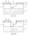
- FIGS. 1A-1Eare pictorial representations (through cross-sectional views) illustrating the basic processing steps that are employed in the present invention for fabricating a BEOL interconnect structure having improved reliability.
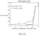
- FIGS. 2A and 2Bare plots showing the breakdown data and breakage data for a hardmask of the present invention that was formed from an OMCATS precursor.
- FIG. 3is the FTIR spectra of a hardmask of the present invention that was formed from an OMCATS precursor.
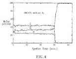
- FIG. 4is the Auger spectra of the OMCATS hardmask of the present invention.
- FIGS. 1A-1Ewhich illustrate the basic processing steps of the present invention, are provided for illustrative purposes and thus they are not drawn to scale.
- FIG. 1Aillustrates a structure that is provided after forming a low k dielectric material 12 on a surface of a substrate 10 .
- substratewhen used in conjunction with substrate 10 includes, a semiconducting material, an insulating material, a conductive material or any combination thereof, including multilayered structures.
- substrate 10can be a semiconducting material such as Si, SiGe, SiGeC, SiC, GaAs, InAs, InP and other III/V or II/VI compound semiconductors.
- the semiconductor substrate 10can also include a layered substrate such as, for example, Si/SiGe, Si/SiC, silicon-on-insulators (SOIs) or silicon germanium-on-insulators (SGOIs).
- the insulating materialcan be an organic insulator, an inorganic insulator or a combination thereof including multilayers.
- the substrate 10may include, for example, polySi, an elemental metal, alloys of elemental metals, a metal silicide, a metal nitride and combinations thereof, including multilayers.
- the substrate 10includes a combination of a semiconducting material and an insulating material, a combination of a semiconducting material and a conductive material or a combination of a semiconducting material, an insulating material and a conductive material.
- CMOScomplementary metal oxide semiconductor
- the low k dielectric material 12can comprise any dielectric material having a dielectric constant of about 3.0 or less. Preferably, the low k dielectric material 12 has a dielectric constant of less than about 2.8, with a dielectric constant of less than about 2.5 being more highly preferred.
- the low k dielectric material 12can be-porous or nonporous. When porous dielectric films are employed, the dielectric constant thereof is less than the nonporous version of the same dielectric film.
- the low k dielectric material 12is a porous material.
- low k dielectricsexamples include, but are not limited to: silicon-containing materials such as a composition of Si, C, O and H (SiCOH) also called C doped oxide (CDO) or organosilicate glass (OSG).
- SiCOHsilicon-containing materials
- CDOC doped oxide
- OSGorganosilicate glass
- Another example of a low k dielectricis a thermosetting polyarylene ether.
- polyaryleneis used herein to denote aryl moieties or inertly substituted aryl moieties which are linked together by bonds, fused rings, or inert linking groups such as oxygen, sulfur, sulfone, sulfoxide, carbonyl, etc.
- the low k dielectric film 12is typically deposited using plasma enhanced chemical vapor deposition (PECVD).
- PECVDplasma enhanced chemical vapor deposition
- the present inventionalso contemplates that the low k dielectric film 12 can be formed utilizing chemical vapor deposition (CVD), high-density plasma (HDP) deposition, pulsed PECVD, spin-on application, or other related methods.
- the thickness of the low k dielectric film 12 depositedmay vary; typical ranges for the deposited low k dielectric film 12 are from about 50 nm to about 1 ⁇ m, with a thickness from 100 to about 500 nm being more typical.
- the low k dielectric film 12is a SiCOH dielectric that is deposited using the processing techniques disclosed in co-assigned U.S. Pat. Nos. 6,147,009, 6,312,793, 6,441,491, 6,437,443, 6,441,491, 6,541,398, 6,479,110 B2, and 6,497,963, the contents of which are incorporated herein by reference.
- the SiCOH dielectric filmis formed by providing at least a first precursor (liquid, gas or vapor) comprising atoms of Si, C, O, and H, and an inert carrier such as He or Ar, into a reactor, preferably the reactor is a PECVD reactor, and then depositing a film derived from said first precursor onto a suitable substrate utilizing conditions that are effective in forming a SiCOH dielectric material.
- a first precursorliquid, gas or vapor
- an inert carriersuch as He or Ar
- the present inventionyet further provides for mixing the first precursor with an oxidizing agent such as O 2 , CO 2 or a combination thereof, thereby stabilizing the reactants in the reactor and improving the uniformity of the low k dielectric film 12 deposited on the substrate 10 .
- a second precursorgas, liquid or vapor
- a third precursorgas, liquid or gas
- Gemay also be used.
- the first precursoris selected from organic molecules with ring structures comprising SiCOH components such as 1, 3, 5, 7-tetramethylcyclotetrasiloxane (“TMCTS” or “C 4 H 16 O 4 Si 4 ”), octamethylcyclotetrasiloxane (OMCTS), diethoxymethylsilane (DEMS), dimethyldimethoxysilane (DMDMOS), diethylmethoxysilane (DEDMOS), and related cyclic and non-cyclic silanes, siloxanes and the like.
- TCTS1, 3, 5, 7-tetramethylcyclotetrasiloxane
- OMCoctamethylcyclotetrasiloxane
- DEMSdiethoxymethylsilane
- DMDMOSdimethyldimethoxysilane
- DEDMOSdiethylmethoxysilane
- the second precursor that may be used in forming a SiCOH low k dielectricis a hydrocarbon molecule.
- any hydrocarbon moleculesuch as, for example, ethylene
- the second precursoris selected from the group consisting of hydrocarbon molecules with ring structures, preferably with more than one ring present in the molecule or with branched chains attached to the ring.
- species containing fused rings, at least one of which contains a heteroatom, preferentially oxygenare those that include a ring of a size that imparts significant ring strain, namely rings of 3 or 4 atoms and/or 7 or more atoms.
- oxabicyclicssuch as cyclopentene oxide (“CPO” or “C 5 H 8 O”).
- CPOcyclopentene oxide
- the third precursormay be formed from germane hydride or any other reactant comprising a source Ge.
- the SiCOH dielectric filmwhich is used as the low k dielectric 12
- the SiCOH dielectric filmmay be deposited using a method the includes the step of providing a parallel plate reactor, which has a conductive area of a substrate chuck between about 85 cm 2 and about 750 cm 2 , and a gap between the substrate and a top electrode between about 1 cm and about 12 cm.
- a high frequency RF poweris applied to one of the electrodes at a frequency between about 0.45 MHz and about 200 MHz.
- an additional low frequency powercan be applied to one of the electrodes.
- the conditions used for the deposition stepmay vary depending on the desired final dielectric constant of the SiCOH dielectric film.
- the conditions used for providing a stable dielectric material comprising elements of Si, C, O and H that has a dielectric constant of about 2.8 or lessinclude: setting the substrate temperature at between about 200° C.
- setting the high frequency RF power densityat between about 0.1 W/cm 2 and about 2.5 W/cm 2 ; setting the first liquid precursor flow rate at between about 100 mg/min and about 5000 mg/min, optionally setting the second liquid precursor flow rate at between about 50 mg/min to about 10,000 mg/min; optionally setting the third liquid precursor flow rate at between about 25 mg/min to about 4000 mg/min; optionally setting the inert carrier gases such as helium (and/or argon) flow rate at between about 50 sccm to about 5000 sccm; setting the reactor pressure at a pressure between about 1000 mTorr and about 7000 mTorr; and setting the high frequency RF power between about 75 W and about 1000 W.
- a low frequency powermay be added to the plasma between about 30 W and about 400 W.
- the RF power applied to the substrate chuckis also changed by a factor of X.
- an oxidizing agentWhen employed in the present invention, it is flown into the PECVD reactor at a flow rate between about 10 sccm to about 1000 sccm.
- the organosilicon gas phase precursorssuch as trimethylsilane
- a porogencan be included during the deposition of the low k dielectric film 12 that causes subsequent pore formation within the film 12 during a subsequent curing step.
- the subsequent curingcan be achieved utilizing one of the treatment steps described herein below.
- the curing of the low k dielectric film 12can be done prior to deposition of the hardmask 14 , or after deposition of the hardmask 14 .
- the low k dielectric film 12 and the hardmask 14are treated at the same time.
- the low k dielectric film 12 formed at this point of the present inventioncontains a matrix of a hydrogenated oxidized silicon carbon material (SiCOH) comprising atoms of Si, C, O and H in a covalently bonded tri-dimensional network and having a dielectric constant of not more than about 2.8.
- the tri-bonded networkmay include a covalently bonded tri-dimensional ring structure comprising Si—O, Si—C, Si—H, C—H and C—C bonds.
- the low k dielectric film 12may comprise F and N and may optionally have the Si atoms partially substituted by Ge atoms.
- the low k dielectric film 12may contain molecular scale voids (i.e., nanometer-sized pores) of between about 0.3 to about 50 nanometers in diameter, and most preferably between about 0.4 and about 10 nanometers in diameter, further reducing the dielectric constant of the film 12 to values below about 2.0.
- the nanometer-sized pores of the low k dielectric film 12occupy a volume of between about 0.5% and about 50% of a volume of the material.
- the low k dielectric film 12When the low k dielectric film 12 is a SiCOH dielectric, it typically comprises between about 5 and about 40 atomic percent of Si; between about 5 and about 45 atomic percent of C; between 0 and about 50 atomic percent of O; and between about 10 and about 55 atomic percent of H.
- a hardmask 14is formed on top of the low k dielectric film 12 .
- the inventive hardmask 14includes a lower region 14 A and an upper region 14 B.
- the lower region 14 A of the inventive hardmask 14has a surface that is positioned on the surface of the low k dielectric 12 .
- the lower region 14 A of the hardmask 14comprises a hermetic oxide material which includes less than about 10 atomic percent (%) C. More typically, the lower region 14 A comprises less than about 5 atomic % C. It is noted that the C content in the lower region 14 A that is in close proximity to the low k dielectric 12 is lower than the other areas within the hardmask 14 . Hence, the inventive hardmask 14 has a graded C content which is lowest in proximity to the low k dielectric 12 and increases the further one gets from the upper surface of the low k dielectric 12 .
- the lower regionis a region within the hardmask 14 that is substantially impervious to external influences such as air or moisture providing a built in sealing layer that prevents air or moisture from penetrating into the underlying low k dielectric film 12 . That is, the lower region 14 A is a barrier region which prevents contaminants such as air or moisture from entering into the low k dielectric 12 .
- the lower region 14 A of the inventive hardmask 14is a thin region having a thickness on the order of about 0.5 to about 10 nm. More typically, the thickness of the lower region 14 A has a thickness from about 1 to about 5 nm.
- the upper region 14 B of the inventive hardmask 14which comprises atoms of Si, C, H and optionally O, N, or a mixture of O and N, serves as a chemical mechanical polishing (CMP) etch stop layer.
- CMPchemical mechanical polishing
- the thickness of the upper region 14 B of the inventive hardmask 14is from about 5 to about 100 nm, with a thickness from about 10 to about 50 nm being more typical.
- the upper region 14 B of the inventive hardmask 14comprises from about 10 to about 80 atomic % C, from about 10 to about 80 atomic % Si, and from about 5 to about 40 atomic % H.
- the upper region 14 Bcomprises from about 30 to about 60 atomic % C, from about 30 to about 60 atomic % Si, and from about 10 to about 30 atomic % H.
- OWhen present in the upper region, it typically is present in an amount from about 5 to about 40 atomic %, with an amount from about 10 to about 20 atomic % being even more typical.
- NWhen present in the upper region, it typically is present in an amount from about 5 to about 40 atomic %, with an amount from about 10 to about 30 atomic % being even more typical.
- the hardmask 14is a dense layer typically having a density from about 1.0 to about 1.9 gm/cm 3 (the density of the lower region 14 A is slightly greater than that of the overall hardmask 14 ; a typical range is from about 1.2 to about 2.3 gm/cm 3 ) and the dielectric constant thereof is typically on the same order as that of the low k dielectric film 12 .
- the hardmask 14(including the lower region 14 A and the upper region 14 B) has a total thickness from about 5 to about 100 nm, with a total thickness from about 10 to about 50 nm being more typical.
- the hardmask 14provides high moisture resistance as well as good adhesion and CMP barrier properties to the interconnect structure.
- the dense, graded hardmask 14is substantially defect free meaning that it does not contain pinholes or micro-channels therein.
- the presence of pinholes and micro-channels within the hardmaskcould lead to moisture and air penetration into the underlying low k dielectric 12 .
- the hardmask 14is formed by utilizing a deposition process including, for example, high density plasma (HPD) deposition, downstream HPD deposition, electron cyclotron resonance assisted PECVD, plasma enhanced atomic layer deposition (PE ALD), ALD or other related deposition processes.
- HPDhigh density plasma
- PE ALDplasma enhanced atomic layer deposition
- ALDALD or other related deposition processes.
- the inventive hardmask 14is formed by placing the substrate 10 inside a reactor chamber of a PECVD apparatus, HDP apparatus, PE ALD apparatus, ECR plasma enhanced CVD apparatus, ALD apparatus or other like apparatuses. Within the reactor chamber, the low k dielectric 12 is applied and thereafter the hardmask 14 is formed. The formation of the low k dielectric 12 and the hardmask 14 can be performed without breaking the vacuum within the reactor chamber. Alternatively, but less preferably, the vacuum can be broken between the deposition of the low k dielectric 12 and the hardmask 14 .
- the hardmask 14is formed by selecting at least two precursor molecules including at least a Si or organosilane source and an oxygen source which are introduced into the reactor chamber either as single stream or as a mixture. The precursor molecules can be in the liquid or vapor form prior to being introduced into the reactor chamber but once inside the chamber a vapor or plasma thereof is formed and is used to deposit the hardmask 14 on the low k dielectric 12 .
- the precursor molecules used in the present invention for forming the hardmask 14include a Si or organosilicon source and an oxygen source.
- a carbon source, and/or a nitrogen source, such as ammoniacan be used in some instances as well.
- the first precursor used in forming the hardmask 14may include the same Si or organosilicon precursor as used in forming the low k dielectric 12 .
- the Si or organosilicon source used in forming the inventive hardmask 14may comprise organic molecules with ring structures comprising SiCOH components such as 1, 3, 5, 7-tetramethylcyclotetrasiloxane (“TMCTS” or “C 4 H 16 O 4 Si 4 ”), octamethylcyclotetrasiloxane (OMCTS), diethoxymethylsilane (DEMS), dimethyldimethoxysilane (DMDMOS), diethylmethoxysilane (DEDMOS), and related cyclic and non-cyclic silanes, siloxanes and the like.
- TCTS1, 3, 5, 7-tetramethylcyclotetrasiloxane
- OMCoctamethylcyclotetrasiloxane
- DEMSdiethoxymethylsilane
- DMDMOSdimethyldime
- the oxygen source that is used in conjunction with the first precursor mentioned in the previous paragraphincludes O 2 , CO 2 or a mixture thereof.
- the dense, graded hardmask 14is formed by introducing an excess of the oxygen source into the reactor during the initial deposition. As the deposition proceeds, the flow of the oxygen source into the reactor is decreased to obtain a steady state composition. Typically, during the initial stage of hardmask 14 deposition, the flow of the oxygen source into the reactor is from about 50 to about 500 sccm, while the flow of the first precursor is from about 50 to about 2000 sccm. For liquid precursor, the flow is 100 mgm to about 4000 mgm.
- the flow of the oxygen sourceis decreased to a range from about 0 to about 250 sccm, while the flow rate of the first precursor is from about 100 to about 1000 sccm (or 1000 to about 2800 mgm for liquid precursor).
- the optional C source that may be used in forming the hardmask 14is a hydrocarbon molecule.
- any hydrocarbon moleculesuch as, for example, ethylene or methane, may be used in forming the hardmask 14
- the optional sourceis selected from the group consisting of hydrocarbon molecules with ring structures, preferably with more than one ring present in the molecule or with branched chains attached to the ring.
- species containing fused rings, at least one of which contains a heteroatom, preferentially oxygenare those that include a ring of a size that imparts significant ring strain, namely rings of 3 or 4 atoms and/or 7 or more atoms.
- oxabicyclicssuch as cyclopentene oxide (“CPO” or “C 5 H 8 O”).
- CPOcyclopentene oxide
- Typical flow rates from the optional C source used in hardmask 14 depositionare from about 100 to about 1000 sccm, with a flow rate from about 200 to about 400 sccm being even more typical.
- An inert carriersuch as He or Ar may be used in conjunction with sources mentioned above.
- the deposition of the hardmask 14is typically performed at low pressures (on the order of about 50 to about 8000 milliTorr, e.g., mTorr), low temperatures (on the order of less than 420° C.) and at a low RF source and bias power (less than 800 watts for a 200 mm system).
- the hardmask 14may optionally be treated utilizing an energy source such as thermal, electron beam, plasma or optical radiation such as UV or laser. Combinations of the aforementioned energy sources can also be used in the present invention.
- the thermal energy sourceincludes any source such as, for example, a heating element or a lamp, that can heat the deposited hardmask 14 to a temperature up to 450° C. More preferably, the thermal energy source is capable of heating the hardmask 14 to a temperature from about 200 to about 450° C., with a temperature from about 350° C. to about 425° C. being even more preferred.
- This thermal treatment processcan be carried out for various time periods, with a time period from about 0.5 minutes to about 300 minutes being typical.
- the thermal treatment stepis typically performed in the presence of an inert gas such as He, Ar, Ne, Xe, N 2 or a mixture thereof.
- the thermal treatment stepmay be referred to as an anneal step in which rapid thermal anneal, furnace anneal, laser anneal or spike anneal conditions are employed.
- the thermal treatment stepcan be performed in the presence of a gas mixture containing a hydrogen source gas such as, for example, H 2 or a hydrocarbon.
- the thermal treatment stepcan be performed in the presence of a gas mixture containing a very low partial pressure of O 2 and H 2 O, in the range below 1000 parts per million.
- the UV light treatment stepis performed utilizing a source that can generate light having a wavelength from about 500 to about 150 nm, to irradiate the substrate while the wafer temperature is maintained at up to 450° C., with temperatures from 200° C.-450° C. being preferred and a temperature from 350° C. to 425° C. being even more highly preferred. Radiation with >370 nm is of insufficient energy to dissociate or activate important bonds, so the wavelength range 150-370 nm is a preferred range. Using literature data and absorbance spectra measured on as deposited films, the inventors have found that ⁇ 170 nm radiation may not be favored due to degradation of the SiCOH film.
- the energy range 310-370 nmis less useful than the range 150-310 nm, due to the relatively low energy per photon from 310-370 nm.
- optimum overlap with the absorbance spectrum of the as deposited film and minimum degradation of the film propertiesmay be optionally used to select a most effective region of the UV spectrum for changing the SiCOH properties.
- the UV light treatment stepmay be performed in an inert gas, a hydrogen source gas or a gas mixture of O 2 and H 2 O using the partial pressure range mentioned above.
- the electron beam treatment stepis performed utilizing a source that is capable of generating a uniform electron flux over the wafer, with energies from 0.5 to 25 keV and current densities from 0.1 to 100 microAmp/cm 2 (preferably 1 to 5 microAmp/cm 2 ), while the wafer temperature is maintained at a temperature up to 450° C., with temperatures from 200°-450° C. being preferred, and temperature from 350° to 425° being even more highly preferred.
- the preferred dose of electrons used in the electron beam treatment stepis from 50 to 500 microcoulombs/cm 2 , with 100 to 300 microcoulombs/cm 2 range being preferred.
- the electron beam treatment stepmay be performed in an inert gas, a hydrogen source gas or a gas mixture of O 2 and H 2 O using the partial pressure range mentioned above.
- the plasma treatment stepis performed utilizing a source that is capable of generating atomic hydrogen (H), and optionally CH 3 or other hydrocarbon radicals. Downstream plasma sources are preferred over direct plasma exposure.
- the wafer temperatureis maintained at a temperature up to 450° C., with temperatures from 200° C.-450° C. being preferred and temperatures from 350° C. to 425° C. being more highly preferred.
- the plasma treatment stepis performed by introducing a gas into a reactor that can generate a plasma and thereafter it is converted into a plasma.
- the gas that can be used for the plasma treatmentincludes inert gases such as Ar, N, He, Xe or Kr, with He being preferred; hydrogen or related sources of atomic hydrogen, methane, methylsilane, related sources of CH 3 groups, and mixtures thereof.
- the flow rate of the plasma treatment gasmay vary depending on the reactor system being used.
- the chamber pressurecan range anywhere from 0.05 to 20 torr, but the preferred range of pressure operation is 1 to 10 torr.
- the plasma treatment stepoccurs for a period of time, which is typically from about 1 ⁇ 2 to about 10 minutes, although longer times may be used within the invention.
- the RF power sourcemay operate at either a high frequency range (on the order of about 100 W or greater); a low frequency range (less than 250 W) or a combination thereof may be employed.
- the high frequency power densitycan range anywhere from 0.1 to 2.0 W/cm 2 but the preferred range of operation is 0.2 to 1.0 W/cm 2 .
- the low frequency power densitycan range anywhere from 0.1 to 1.0 W/cm 2 but the preferred range of operation is 0.2 to 0.5 W/cm 2 .
- the chosen power levelsmust be low enough to avoid significant sputter etching of the exposed dielectric surface ( ⁇ 5 nanometers removal).
- a deep ultra-violet (DUV) laser sourcecan also be employed.
- the laser source used to treat the deposited hardmask 14is typically an excimer laser which operates at one of several DUV wavelengths depending on the laser gas mixture.
- a XeF laserwhich produces 308 nm radiation can be employed.
- a KrF laserthat produces 248 nm radiation, or a ArF laser that produces 193 nm radiation can be employed in the present invention.
- Excimer laserscan operate at several hundred pulses per second with pulse energies up to a Joule (J) resulting in several hundred Watt (W) output.
- the laser employed in treating the as deposited hardmask 14preferably operates under a pulse mode.
- the laser beamcan be expanded to expose the entire sample. Alternatively, and for larger samples, the laser exposure area can be raster scanned across the sample to provide uniform dose.
- the fluenceis limited to less than 5 mJ/cm 2 per pulse to ensure ablation will not occur.
- the short pulse duration of about 10 ns for the excimer lasercan cause material ablation at fluence levels greater than 20 mJ/cm 2 .
- laser fluence levels of 0.1-5 mJ/cm 2 per pulseare employed.
- the total dosecan vary from 1 to 10000 Joules/cm 2 , preferably 500-2000 J/cm 2 .
- a dose of 1000 J/cm 2can be obtained using a fluence of 1 mJ/cm 2 for duration of 10 6 pulses.
- Excimer lasernormally operates at a few hundreds pulses per second.
- the overall exposure time period for the DUV laser treatmentfor a several seconds to hours.
- a typical 500 J/cm 2 doseis achieved in less than 15 min using a 200 Hz laser operating at a fluence level of 3 mJ/cm 2 per pulse.
- the treatment step mentioned abovecauses activation of the as deposited hardmask 14 .
- the above treatment stepcauses cross-linking in the hardmask which, in turn, causes bulk bonding.
- the treatment stepdrives out any weak bonding structure present in the hardmask by thermal heating and photon energy which causes the hardmask to become much more stable under low thermal heating energy.
- a photoresist material(not shown) is applied to the surface of the hardmask 14 and then lithography is used to provide a pattern into the photoresist material.
- the pattern formed at this pointis typically a via pattern.
- a via patternis particularly described and illustrated at this point of the present invention, a line pattern can be formed instead.
- the via patternis transferred into the hardmask 14 , and thereafter into the low k dielectric 12 utilizing one or more etching steps.
- the patterned resistis typically removed after the hardmask 14 has been etched.
- the etching stepsinclude a first etch that selectively removes the exposed portion of the hardmask 14 not covered by the patterned photoresist material.
- This first etchcomprises a dry etching process such as reactive ion etching, ion beam etching or plasma etching.
- a dry etching processsuch as reactive ion etching, ion beam etching or plasma etching.
- the subsequent second patterning step of the present inventionis not used.
- the second patterning stepcomprises applying another resist material (not shown) to the structure and then lithography is used to provide a line pattern which is transferred into the hardmask 14 and a portion of the low k dielectric 12 utilizing an etching process which includes one or more dry etching steps.
- the line patternis formed into an upper portion of the low k dielectric 12 .
- reference numeral 16denotes the opening that is created into the low k dielectric 12 using the above processing steps.
- the opening 16includes a via region 18 and a line region 20 .
- the linecan be formed first and then the via can be formed. In yet other embodiments, only a via or line opening is formed.
- At least one liner 22is then formed on all exposed surfaces (vertical and horizontal) within the opening 16 created above so as to provide the structure shown in FIG. 1D .
- the liner 22is formed by any deposition process including, but not limited to: CVD, PECVD, sputtering, chemical solution deposition or plating.
- the liner 22is comprised of any material that can serve as a barrier to prevent a conductive material from diffusing there through.
- barrier materialsinclude a refractory metal, such as Ta, Ti, W, Ru, or nitrides thereof, e.g., TaN, TiN, WN.
- the liner 22may also comprise TiNSi.
- the thickness of the liner 22is typically from about 5 to about 60 nm, with a thickness from about 10 to about 40 nm being more typical.
- the liner 22it is possible to remove the liner 22 from the bottom wall of the via 20 to provide an interconnect structure having an open via bottom.
- an ion bombardment or other like directional etching processis employed.
- a conductive material 24is deposited within the opening 16 .
- the conductive material 24comprises polySi, a conductive metal, an alloy comprising at least one conductive metal, a conductive metal silicide or combinations thereof.
- the conductive material 24is a conductive metal such as Cu, W, or Al.
- the conductive material 24is comprised of Cu.
- the conductive material 24is formed within the opening 16 utilizing a conventional deposition process including, but not limited to: CVD, PECVD, sputtering, chemical solution deposition or plating.
- a planarization processcan be employed such that the upper surface of the conductive material 24 is substantially coplanar with the upper surface of the low k dielectric 12 or, if present and not removed by the planarization step, the upper surface of the hardmask 14 .
- FIG. 1Ethe latter embodiment is shown.
- the conductively filled openingcan be referred to herein as a conductive feature that is embedded within the low k dielectric 12 .
- the above processingmay be repeated any number of times to provide a multilevel interconnect structure.
- the multilevel interconnect structureis not limited to any number, current technologies has from about 2 to about 10 interconnect levels.
- the FTIR spectrum shown in FIG. 3reveals a typical plasma SiCOH film structure with stable Si—O, Si—CH 3 , Si—H and cross-linking Si—CH 2 —Si bonding in the film.
- the typical Auger Profile ( FIG. 4 ) of SiCOH film without O 2 precursorshowed good depth profile uniformity.
- FIGS. 2-4showed a stable bonding structure and excellent electrical properties for the inventive hardmask.
- the hardmasks of the present inventionhad good CMP resistance properties under the described deposition process conditions.
Landscapes
- Engineering & Computer Science (AREA)
- Physics & Mathematics (AREA)
- Condensed Matter Physics & Semiconductors (AREA)
- General Physics & Mathematics (AREA)
- Computer Hardware Design (AREA)
- Microelectronics & Electronic Packaging (AREA)
- Power Engineering (AREA)
- Manufacturing & Machinery (AREA)
- Plasma & Fusion (AREA)
- Spectroscopy & Molecular Physics (AREA)
- Internal Circuitry In Semiconductor Integrated Circuit Devices (AREA)
Abstract
Description
| TABLE | |||||
| OMCATS | OMCATS | OMCATS | |||
| HM | |||||
| 1 | HM 3 | ||||
| 300 mm | 300 mm | 300 mm | 200 mm* | ||
| OMCATS Flow (mgm) | 2000 | 2500 | 2800 | 1800 |
| O2Flow (sccm) | 0 | 160 | 220 | 0 |
| 1000 | 1000 | 1000 | 500 | |
| Flow (sccm) | ||||
| Temp. (° C.) | 350 | 350 | 350 | 350 |
| Pressure (Torr) | 5 | 5 | 5 | 5 |
| Spacing (mils) | 450 | 450 | 450 | 450 |
| HF power (W) | 500 | 500 | 400 | 500 |
| LF power (W) | 0 | 150 | 60 | 75 |
| *For | ||||
Claims (13)
Priority Applications (4)
| Application Number | Priority Date | Filing Date | Title |
|---|---|---|---|
| US10/981,233US7335980B2 (en) | 2004-11-04 | 2004-11-04 | Hardmask for reliability of silicon based dielectrics |
| CNB2005101173780ACN100388477C (en) | 2004-11-04 | 2005-11-03 | Interconnect structure and method of forming the same |
| US12/016,594US7485582B2 (en) | 2004-11-04 | 2008-01-18 | Hardmask for improved reliability of silicon based dielectrics |
| US12/018,640US20080118717A1 (en) | 2004-11-04 | 2008-01-23 | Hardmask for improved reliability of silicon based dielectrics |
Applications Claiming Priority (1)
| Application Number | Priority Date | Filing Date | Title |
|---|---|---|---|
| US10/981,233US7335980B2 (en) | 2004-11-04 | 2004-11-04 | Hardmask for reliability of silicon based dielectrics |
Related Child Applications (2)
| Application Number | Title | Priority Date | Filing Date |
|---|---|---|---|
| US12/016,594DivisionUS7485582B2 (en) | 2004-11-04 | 2008-01-18 | Hardmask for improved reliability of silicon based dielectrics |
| US12/018,640ContinuationUS20080118717A1 (en) | 2004-11-04 | 2008-01-23 | Hardmask for improved reliability of silicon based dielectrics |
Publications (2)
| Publication Number | Publication Date |
|---|---|
| US20060091559A1 US20060091559A1 (en) | 2006-05-04 |
| US7335980B2true US7335980B2 (en) | 2008-02-26 |
Family
ID=36260892
Family Applications (3)
| Application Number | Title | Priority Date | Filing Date |
|---|---|---|---|
| US10/981,233Expired - LifetimeUS7335980B2 (en) | 2004-11-04 | 2004-11-04 | Hardmask for reliability of silicon based dielectrics |
| US12/016,594Expired - Fee RelatedUS7485582B2 (en) | 2004-11-04 | 2008-01-18 | Hardmask for improved reliability of silicon based dielectrics |
| US12/018,640AbandonedUS20080118717A1 (en) | 2004-11-04 | 2008-01-23 | Hardmask for improved reliability of silicon based dielectrics |
Family Applications After (2)
| Application Number | Title | Priority Date | Filing Date |
|---|---|---|---|
| US12/016,594Expired - Fee RelatedUS7485582B2 (en) | 2004-11-04 | 2008-01-18 | Hardmask for improved reliability of silicon based dielectrics |
| US12/018,640AbandonedUS20080118717A1 (en) | 2004-11-04 | 2008-01-23 | Hardmask for improved reliability of silicon based dielectrics |
Country Status (2)
| Country | Link |
|---|---|
| US (3) | US7335980B2 (en) |
| CN (1) | CN100388477C (en) |
Cited By (8)
| Publication number | Priority date | Publication date | Assignee | Title |
|---|---|---|---|---|
| US20070010070A1 (en)* | 2005-07-05 | 2007-01-11 | International Business Machines Corporation | Fabrication of strained semiconductor-on-insulator (ssoi) structures by using strained insulating layers |
| US20070173070A1 (en)* | 2006-01-26 | 2007-07-26 | Mei-Ling Chen | Porous low-k dielectric film and fabrication method thereof |
| US20080099920A1 (en)* | 2004-03-31 | 2008-05-01 | Applied Materials, Inc. A Delaware Corporation | Multi-stage curing of low k nano-porous films |
| US20080233366A1 (en)* | 2007-03-23 | 2008-09-25 | International Business Machines Corporation | STRUCTURE AND METHOD FOR SiCOH INTERFACES WITH INCREASED MECHANICAL STRENGTH |
| US7642202B1 (en)* | 2001-06-28 | 2010-01-05 | Novellus Systems, Inc. | Methods of forming moisture barrier for low k film integration with anti-reflective layers |
| US20100015970A1 (en)* | 2005-12-21 | 2010-01-21 | Huaiyu Zeng | Method and system for decoding control channels using repetition redundancy |
| US20180233375A1 (en)* | 2015-05-08 | 2018-08-16 | Macronix International Co., Ltd. | Method of fabricating semiconductor device |
| US11681213B2 (en) | 2019-02-21 | 2023-06-20 | International Business Machines Corporation | EUV pattern transfer using graded hardmask |
Families Citing this family (88)
| Publication number | Priority date | Publication date | Assignee | Title |
|---|---|---|---|---|
| US7208389B1 (en) | 2003-03-31 | 2007-04-24 | Novellus Systems, Inc. | Method of porogen removal from porous low-k films using UV radiation |
| US7341761B1 (en) | 2004-03-11 | 2008-03-11 | Novellus Systems, Inc. | Methods for producing low-k CDO films |
| US7781351B1 (en) | 2004-04-07 | 2010-08-24 | Novellus Systems, Inc. | Methods for producing low-k carbon doped oxide films with low residual stress |
| US7253125B1 (en) | 2004-04-16 | 2007-08-07 | Novellus Systems, Inc. | Method to improve mechanical strength of low-k dielectric film using modulated UV exposure |
| US7223670B2 (en)* | 2004-08-20 | 2007-05-29 | International Business Machines Corporation | DUV laser annealing and stabilization of SiCOH films |
| US9659769B1 (en) | 2004-10-22 | 2017-05-23 | Novellus Systems, Inc. | Tensile dielectric films using UV curing |
| US7790633B1 (en) | 2004-10-26 | 2010-09-07 | Novellus Systems, Inc. | Sequential deposition/anneal film densification method |
| US7695765B1 (en) | 2004-11-12 | 2010-04-13 | Novellus Systems, Inc. | Methods for producing low-stress carbon-doped oxide films with improved integration properties |
| KR100632658B1 (en)* | 2004-12-29 | 2006-10-12 | 주식회사 하이닉스반도체 | Metal wiring formation method of semiconductor device |
| US7351656B2 (en)* | 2005-01-21 | 2008-04-01 | Kabushiki Kaihsa Toshiba | Semiconductor device having oxidized metal film and manufacture method of the same |
| US7166531B1 (en) | 2005-01-31 | 2007-01-23 | Novellus Systems, Inc. | VLSI fabrication processes for introducing pores into dielectric materials |
| US7510982B1 (en) | 2005-01-31 | 2009-03-31 | Novellus Systems, Inc. | Creation of porosity in low-k films by photo-disassociation of imbedded nanoparticles |
| US7790630B2 (en)* | 2005-04-12 | 2010-09-07 | Intel Corporation | Silicon-doped carbon dielectrics |
| US8282768B1 (en) | 2005-04-26 | 2012-10-09 | Novellus Systems, Inc. | Purging of porogen from UV cure chamber |
| US8980769B1 (en) | 2005-04-26 | 2015-03-17 | Novellus Systems, Inc. | Multi-station sequential curing of dielectric films |
| US8889233B1 (en) | 2005-04-26 | 2014-11-18 | Novellus Systems, Inc. | Method for reducing stress in porous dielectric films |
| US8137465B1 (en) | 2005-04-26 | 2012-03-20 | Novellus Systems, Inc. | Single-chamber sequential curing of semiconductor wafers |
| US8454750B1 (en) | 2005-04-26 | 2013-06-04 | Novellus Systems, Inc. | Multi-station sequential curing of dielectric films |
| US8664124B2 (en) | 2005-10-31 | 2014-03-04 | Novellus Systems, Inc. | Method for etching organic hardmasks |
| US7892985B1 (en) | 2005-11-15 | 2011-02-22 | Novellus Systems, Inc. | Method for porogen removal and mechanical strength enhancement of low-k carbon doped silicon oxide using low thermal budget microwave curing |
| US8110493B1 (en) | 2005-12-23 | 2012-02-07 | Novellus Systems, Inc. | Pulsed PECVD method for modulating hydrogen content in hard mask |
| KR100717501B1 (en)* | 2005-12-29 | 2007-05-14 | 동부일렉트로닉스 주식회사 | Metal wiring formation method of semiconductor device |
| US7981810B1 (en) | 2006-06-08 | 2011-07-19 | Novellus Systems, Inc. | Methods of depositing highly selective transparent ashable hardmask films |
| US10037905B2 (en) | 2009-11-12 | 2018-07-31 | Novellus Systems, Inc. | UV and reducing treatment for K recovery and surface clean in semiconductor processing |
| US8465991B2 (en)* | 2006-10-30 | 2013-06-18 | Novellus Systems, Inc. | Carbon containing low-k dielectric constant recovery using UV treatment |
| US7851232B2 (en)* | 2006-10-30 | 2010-12-14 | Novellus Systems, Inc. | UV treatment for carbon-containing low-k dielectric repair in semiconductor processing |
| US7906174B1 (en) | 2006-12-07 | 2011-03-15 | Novellus Systems, Inc. | PECVD methods for producing ultra low-k dielectric films using UV treatment |
| US7915166B1 (en) | 2007-02-22 | 2011-03-29 | Novellus Systems, Inc. | Diffusion barrier and etch stop films |
| US7981777B1 (en)* | 2007-02-22 | 2011-07-19 | Novellus Systems, Inc. | Methods of depositing stable and hermetic ashable hardmask films |
| JP5277552B2 (en)* | 2007-03-19 | 2013-08-28 | 富士通セミコンダクター株式会社 | Manufacturing method of semiconductor device |
| US8242028B1 (en) | 2007-04-03 | 2012-08-14 | Novellus Systems, Inc. | UV treatment of etch stop and hard mask films for selectivity and hermeticity enhancement |
| US7622162B1 (en) | 2007-06-07 | 2009-11-24 | Novellus Systems, Inc. | UV treatment of STI films for increasing tensile stress |
| US20090061649A1 (en) | 2007-08-28 | 2009-03-05 | International Business Machines Corporation | LOW k POROUS SiCOH DIELECTRIC AND INTEGRATION WITH POST FILM FORMATION TREATMENT |
| US20090061237A1 (en)* | 2007-08-28 | 2009-03-05 | International Business Machines Corporation | LOW k POROUS SiCOH DIELECTRIC AND INTEGRATION WITH POST FILM FORMATION TREATMENT |
| US8962101B2 (en) | 2007-08-31 | 2015-02-24 | Novellus Systems, Inc. | Methods and apparatus for plasma-based deposition |
| US8211510B1 (en) | 2007-08-31 | 2012-07-03 | Novellus Systems, Inc. | Cascaded cure approach to fabricate highly tensile silicon nitride films |
| US20090104541A1 (en)* | 2007-10-23 | 2009-04-23 | Eui Kyoon Kim | Plasma surface treatment to prevent pattern collapse in immersion lithography |
| US7820556B2 (en)* | 2008-06-04 | 2010-10-26 | Novellus Systems, Inc. | Method for purifying acetylene gas for use in semiconductor processes |
| US8435608B1 (en) | 2008-06-27 | 2013-05-07 | Novellus Systems, Inc. | Methods of depositing smooth and conformal ashable hard mask films |
| US9050623B1 (en) | 2008-09-12 | 2015-06-09 | Novellus Systems, Inc. | Progressive UV cure |
| US20100151206A1 (en)* | 2008-12-11 | 2010-06-17 | Air Products And Chemicals, Inc. | Method for Removal of Carbon From An Organosilicate Material |
| US7955990B2 (en)* | 2008-12-12 | 2011-06-07 | Novellus Systems, Inc. | Method for improved thickness repeatability of PECVD deposited carbon films |
| JP2010171081A (en)* | 2009-01-20 | 2010-08-05 | Toshiba Corp | Semiconductor device and manufacturing method thereof |
| US10032569B2 (en)* | 2009-08-26 | 2018-07-24 | University Of Maryland, College Park | Nanodevice arrays for electrical energy storage, capture and management and method for their formation |
| US8912522B2 (en)* | 2009-08-26 | 2014-12-16 | University Of Maryland | Nanodevice arrays for electrical energy storage, capture and management and method for their formation |
| US8048810B2 (en)* | 2010-01-29 | 2011-11-01 | Taiwan Semiconductor Manufacturing Company, Ltd. | Method for metal gate N/P patterning |
| US8741394B2 (en) | 2010-03-25 | 2014-06-03 | Novellus Systems, Inc. | In-situ deposition of film stacks |
| US8563414B1 (en) | 2010-04-23 | 2013-10-22 | Novellus Systems, Inc. | Methods for forming conductive carbon films by PECVD |
| US8252699B2 (en)* | 2010-11-22 | 2012-08-28 | Applied Materials, Inc. | Composite removable hardmask |
| CN102543844B (en)* | 2010-12-30 | 2014-05-14 | 中芯国际集成电路制造(上海)有限公司 | Method for manufacturing semiconductor device structure and semiconductor device structure |
| KR101829281B1 (en)* | 2011-06-29 | 2018-02-20 | 삼성전자주식회사 | Method for forming dielectric layer of ONO structure using in-situ process |
| WO2013101028A1 (en)* | 2011-12-29 | 2013-07-04 | Intel Corporation | Avd hardmask for damascene patterning |
| SG195494A1 (en) | 2012-05-18 | 2013-12-30 | Novellus Systems Inc | Carbon deposition-etch-ash gap fill process |
| US12334332B2 (en) | 2012-06-12 | 2025-06-17 | Lam Research Corporation | Remote plasma based deposition of silicon carbide films using silicon-containing and carbon-containing precursors |
| US10832904B2 (en) | 2012-06-12 | 2020-11-10 | Lam Research Corporation | Remote plasma based deposition of oxygen doped silicon carbide films |
| US10325773B2 (en) | 2012-06-12 | 2019-06-18 | Novellus Systems, Inc. | Conformal deposition of silicon carbide films |
| US20180347035A1 (en) | 2012-06-12 | 2018-12-06 | Lam Research Corporation | Conformal deposition of silicon carbide films using heterogeneous precursor interaction |
| US9234276B2 (en) | 2013-05-31 | 2016-01-12 | Novellus Systems, Inc. | Method to obtain SiC class of films of desired composition and film properties |
| CN103633018B (en)* | 2012-08-29 | 2016-03-16 | 中芯国际集成电路制造(上海)有限公司 | The formation method of interconnection structure |
| US9966280B2 (en)* | 2012-10-05 | 2018-05-08 | Tokyo Electron Limited | Process gas generation for cleaning of substrates |
| US9362133B2 (en) | 2012-12-14 | 2016-06-07 | Lam Research Corporation | Method for forming a mask by etching conformal film on patterned ashable hardmask |
| US8835306B2 (en)* | 2013-02-01 | 2014-09-16 | GlobalFoundries, Inc. | Methods for fabricating integrated circuits having embedded electrical interconnects |
| US9304396B2 (en) | 2013-02-25 | 2016-04-05 | Lam Research Corporation | PECVD films for EUV lithography |
| US10297442B2 (en)* | 2013-05-31 | 2019-05-21 | Lam Research Corporation | Remote plasma based deposition of graded or multi-layered silicon carbide film |
| US8927442B1 (en) | 2013-07-25 | 2015-01-06 | International Business Machines Corporation | SiCOH hardmask with graded transition layers |
| US9589799B2 (en) | 2013-09-30 | 2017-03-07 | Lam Research Corporation | High selectivity and low stress carbon hardmask by pulsed low frequency RF power |
| US9320387B2 (en) | 2013-09-30 | 2016-04-26 | Lam Research Corporation | Sulfur doped carbon hard masks |
| KR20160011150A (en)* | 2014-07-18 | 2016-01-29 | 어플라이드 머티어리얼스, 인코포레이티드 | Plasma-enhanced and radical-based cvd of porous carbon-doped oxide films assisted by radical curing |
| US9997405B2 (en) | 2014-09-30 | 2018-06-12 | Lam Research Corporation | Feature fill with nucleation inhibition |
| KR20170070083A (en) | 2014-10-15 | 2017-06-21 | 어플라이드 머티어리얼스, 인코포레이티드 | Multi-layer dielectric stack for plasma damage protection |
| CN105826237A (en)* | 2015-01-06 | 2016-08-03 | 中芯国际集成电路制造(上海)有限公司 | Interconnection structure and formation method thereof |
| EP3082172A1 (en)* | 2015-04-16 | 2016-10-19 | Saint-Gobain Glass France | Layered structure for an oled and a method for producing such a structure |
| US20160314964A1 (en) | 2015-04-21 | 2016-10-27 | Lam Research Corporation | Gap fill using carbon-based films |
| KR102460075B1 (en)* | 2016-01-27 | 2022-10-31 | 삼성전자주식회사 | Semiconductor devices and methods of manufacturing semiconductor devices |
| US9847221B1 (en)* | 2016-09-29 | 2017-12-19 | Lam Research Corporation | Low temperature formation of high quality silicon oxide films in semiconductor device manufacturing |
| US10002787B2 (en) | 2016-11-23 | 2018-06-19 | Lam Research Corporation | Staircase encapsulation in 3D NAND fabrication |
| US11749563B2 (en) | 2018-06-27 | 2023-09-05 | Taiwan Semiconductor Manufacturing Co., Ltd. | Interlayer dielectric layer |
| US10840087B2 (en) | 2018-07-20 | 2020-11-17 | Lam Research Corporation | Remote plasma based deposition of boron nitride, boron carbide, and boron carbonitride films |
| WO2020023385A1 (en)* | 2018-07-24 | 2020-01-30 | Lam Research Corporation | Conformal deposition of silicon carbide films using heterogeneous precursor interaction |
| US11043373B2 (en)* | 2018-07-31 | 2021-06-22 | Taiwan Semiconductor Manufacturing Company, Ltd. | Interconnect system with improved low-k dielectrics |
| KR20230085954A (en) | 2018-10-19 | 2023-06-14 | 램 리써치 코포레이션 | Doped or undoped silicon carbide deposition and remote hydrogen plasma exposure for gapfill |
| CN113891954B (en) | 2019-05-29 | 2025-09-19 | 朗姆研究公司 | High selectivity, low stress, and low hydrogen diamond-like carbon hard mask produced by high power pulsed low frequency RF |
| CN110544671A (en)* | 2019-08-26 | 2019-12-06 | 上海新微技术研发中心有限公司 | Method for forming semiconductor structure |
| KR20210028093A (en)* | 2019-08-29 | 2021-03-11 | 에이에스엠 아이피 홀딩 비.브이. | Structures including dielectric layers and methods of forming same |
| KR20220051009A (en) | 2019-08-30 | 2022-04-25 | 램 리써치 코포레이션 | High Density, High Modulus, and High Hardness Amorphous Carbon Films at Low Pressure |
| US11276637B2 (en) | 2019-09-17 | 2022-03-15 | Taiwan Semiconductor Manufacturing Co., Ltd. | Barrier-free interconnect structure and manufacturing method thereof |
| CN113161284B (en)* | 2020-01-07 | 2025-03-14 | 台积电(南京)有限公司 | Method for manufacturing an interconnect structure |
| US12394722B2 (en) | 2020-09-25 | 2025-08-19 | Intel Corporation | Dielectric capacitance recovery of inter-layer dielectric layers for advanced integrated circuit structure fabrication |
Citations (4)
| Publication number | Priority date | Publication date | Assignee | Title |
|---|---|---|---|---|
| US5481135A (en)* | 1992-08-31 | 1996-01-02 | Dow Corning Corporation | Hermetic protection for integrated circuits |
| US6737727B2 (en) | 2001-01-12 | 2004-05-18 | International Business Machines Corporation | Electronic structures with reduced capacitance |
| US6740539B2 (en)* | 2001-07-20 | 2004-05-25 | International Business Machines Corporation | Carbon-graded layer for improved adhesion of low-k dielectrics to silicon substrates |
| US20040203223A1 (en)* | 2003-04-09 | 2004-10-14 | Institute Of Microelectronics | Method to form Cu/OSG dual damascene structure for high performance and reliable interconnects |
Family Cites Families (5)
| Publication number | Priority date | Publication date | Assignee | Title |
|---|---|---|---|---|
| US6417092B1 (en)* | 2000-04-05 | 2002-07-09 | Novellus Systems, Inc. | Low dielectric constant etch stop films |
| US6699784B2 (en)* | 2001-12-14 | 2004-03-02 | Applied Materials Inc. | Method for depositing a low k dielectric film (K>3.5) for hard mask application |
| US6638871B2 (en)* | 2002-01-10 | 2003-10-28 | United Microlectronics Corp. | Method for forming openings in low dielectric constant material layer |
| US20040185674A1 (en)* | 2003-03-17 | 2004-09-23 | Applied Materials, Inc. | Nitrogen-free hard mask over low K dielectric |
| US20040248400A1 (en)* | 2003-06-09 | 2004-12-09 | Kim Sun-Oo | Composite low-k dielectric structure |
- 2004
- 2004-11-04USUS10/981,233patent/US7335980B2/ennot_activeExpired - Lifetime
- 2005
- 2005-11-03CNCNB2005101173780Apatent/CN100388477C/ennot_activeExpired - Fee Related
- 2008
- 2008-01-18USUS12/016,594patent/US7485582B2/ennot_activeExpired - Fee Related
- 2008-01-23USUS12/018,640patent/US20080118717A1/ennot_activeAbandoned
Patent Citations (4)
| Publication number | Priority date | Publication date | Assignee | Title |
|---|---|---|---|---|
| US5481135A (en)* | 1992-08-31 | 1996-01-02 | Dow Corning Corporation | Hermetic protection for integrated circuits |
| US6737727B2 (en) | 2001-01-12 | 2004-05-18 | International Business Machines Corporation | Electronic structures with reduced capacitance |
| US6740539B2 (en)* | 2001-07-20 | 2004-05-25 | International Business Machines Corporation | Carbon-graded layer for improved adhesion of low-k dielectrics to silicon substrates |
| US20040203223A1 (en)* | 2003-04-09 | 2004-10-14 | Institute Of Microelectronics | Method to form Cu/OSG dual damascene structure for high performance and reliable interconnects |
Cited By (12)
| Publication number | Priority date | Publication date | Assignee | Title |
|---|---|---|---|---|
| US7642202B1 (en)* | 2001-06-28 | 2010-01-05 | Novellus Systems, Inc. | Methods of forming moisture barrier for low k film integration with anti-reflective layers |
| US8003549B1 (en) | 2001-06-28 | 2011-08-23 | Novellus Systems, Inc. | Methods of forming moisture barrier for low K film integration with anti-reflective layers |
| US20080099920A1 (en)* | 2004-03-31 | 2008-05-01 | Applied Materials, Inc. A Delaware Corporation | Multi-stage curing of low k nano-porous films |
| US20070010070A1 (en)* | 2005-07-05 | 2007-01-11 | International Business Machines Corporation | Fabrication of strained semiconductor-on-insulator (ssoi) structures by using strained insulating layers |
| US20100015970A1 (en)* | 2005-12-21 | 2010-01-21 | Huaiyu Zeng | Method and system for decoding control channels using repetition redundancy |
| US20070173070A1 (en)* | 2006-01-26 | 2007-07-26 | Mei-Ling Chen | Porous low-k dielectric film and fabrication method thereof |
| US20090275211A1 (en)* | 2006-01-26 | 2009-11-05 | Mei-Ling Chen | Fabrication method of porous low-k dielectric film |
| US20080233366A1 (en)* | 2007-03-23 | 2008-09-25 | International Business Machines Corporation | STRUCTURE AND METHOD FOR SiCOH INTERFACES WITH INCREASED MECHANICAL STRENGTH |
| US7615482B2 (en)* | 2007-03-23 | 2009-11-10 | International Business Machines Corporation | Structure and method for porous SiCOH dielectric layers and adhesion promoting or etch stop layers having increased interfacial and mechanical strength |
| US20180233375A1 (en)* | 2015-05-08 | 2018-08-16 | Macronix International Co., Ltd. | Method of fabricating semiconductor device |
| US10607848B2 (en)* | 2015-05-08 | 2020-03-31 | Macronix International Co., Ltd. | Method of fabricating semiconductor device |
| US11681213B2 (en) | 2019-02-21 | 2023-06-20 | International Business Machines Corporation | EUV pattern transfer using graded hardmask |
Also Published As
| Publication number | Publication date |
|---|---|
| CN100388477C (en) | 2008-05-14 |
| US20060091559A1 (en) | 2006-05-04 |
| US7485582B2 (en) | 2009-02-03 |
| US20080132055A1 (en) | 2008-06-05 |
| CN1783479A (en) | 2006-06-07 |
| US20080118717A1 (en) | 2008-05-22 |
Similar Documents
| Publication | Publication Date | Title |
|---|---|---|
| US7335980B2 (en) | Hardmask for reliability of silicon based dielectrics | |
| US7998880B2 (en) | Low k dielectric CVD film formation process with in-situ imbedded nanolayers to improve mechanical properties | |
| US7253105B2 (en) | Reliable BEOL integration process with direct CMP of porous SiCOH dielectric | |
| US7494938B2 (en) | Advanced low dielectric constant organosilicon plasma chemical vapor deposition films | |
| US7030468B2 (en) | Low k and ultra low k SiCOH dielectric films and methods to form the same | |
| US7755159B2 (en) | DUV laser annealing and stabilization of SiCOH films | |
| US8097932B2 (en) | Ultra low κ plasma enhanced chemical vapor deposition processes using a single bifunctional precursor containing both a SiCOH matrix functionality and organic porogen functionality | |
| US8664109B2 (en) | Advanced low k cap film formation process for nano electronic devices |
Legal Events
| Date | Code | Title | Description |
|---|---|---|---|
| AS | Assignment | Owner name:INTERNATIONAL BUSINESS MACHINES CORPORATION, NEW Y Free format text:ASSIGNMENT OF ASSIGNORS INTEREST;ASSIGNORS:NGUYEN, SON V.;LANE, MICHAEL;GATES, STEPHEN M.;AND OTHERS;REEL/FRAME:015501/0512;SIGNING DATES FROM 20041028 TO 20041102 | |
| FEPP | Fee payment procedure | Free format text:PAYOR NUMBER ASSIGNED (ORIGINAL EVENT CODE: ASPN); ENTITY STATUS OF PATENT OWNER: LARGE ENTITY | |
| STCF | Information on status: patent grant | Free format text:PATENTED CASE | |
| FPAY | Fee payment | Year of fee payment:4 | |
| FPAY | Fee payment | Year of fee payment:8 | |
| AS | Assignment | Owner name:GLOBALFOUNDRIES U.S. 2 LLC, NEW YORK Free format text:ASSIGNMENT OF ASSIGNORS INTEREST;ASSIGNOR:INTERNATIONAL BUSINESS MACHINES CORPORATION;REEL/FRAME:036550/0001 Effective date:20150629 | |
| AS | Assignment | Owner name:GLOBALFOUNDRIES INC., CAYMAN ISLANDS Free format text:ASSIGNMENT OF ASSIGNORS INTEREST;ASSIGNORS:GLOBALFOUNDRIES U.S. 2 LLC;GLOBALFOUNDRIES U.S. INC.;REEL/FRAME:036779/0001 Effective date:20150910 | |
| AS | Assignment | Owner name:WILMINGTON TRUST, NATIONAL ASSOCIATION, DELAWARE Free format text:SECURITY AGREEMENT;ASSIGNOR:GLOBALFOUNDRIES INC.;REEL/FRAME:049490/0001 Effective date:20181127 | |
| MAFP | Maintenance fee payment | Free format text:PAYMENT OF MAINTENANCE FEE, 12TH YEAR, LARGE ENTITY (ORIGINAL EVENT CODE: M1553); ENTITY STATUS OF PATENT OWNER: LARGE ENTITY Year of fee payment:12 | |
| AS | Assignment | Owner name:GLOBALFOUNDRIES U.S. INC., CALIFORNIA Free format text:ASSIGNMENT OF ASSIGNORS INTEREST;ASSIGNOR:GLOBALFOUNDRIES INC.;REEL/FRAME:054633/0001 Effective date:20201022 | |
| AS | Assignment | Owner name:GLOBALFOUNDRIES INC., CAYMAN ISLANDS Free format text:RELEASE BY SECURED PARTY;ASSIGNOR:WILMINGTON TRUST, NATIONAL ASSOCIATION;REEL/FRAME:054636/0001 Effective date:20201117 | |
| AS | Assignment | Owner name:GLOBALFOUNDRIES U.S. INC., NEW YORK Free format text:RELEASE BY SECURED PARTY;ASSIGNOR:WILMINGTON TRUST, NATIONAL ASSOCIATION;REEL/FRAME:056987/0001 Effective date:20201117 |