US7335341B2 - Method for securing ceramic structures and forming electrical connections on the same - Google Patents
Method for securing ceramic structures and forming electrical connections on the sameDownload PDFInfo
- Publication number
- US7335341B2 US7335341B2US10/697,922US69792203AUS7335341B2US 7335341 B2US7335341 B2US 7335341B2US 69792203 AUS69792203 AUS 69792203AUS 7335341 B2US7335341 B2US 7335341B2
- Authority
- US
- United States
- Prior art keywords
- ceramic elements
- particles
- nozzle
- ceramic
- providing
- Prior art date
- Legal status (The legal status is an assumption and is not a legal conclusion. Google has not performed a legal analysis and makes no representation as to the accuracy of the status listed.)
- Expired - Fee Related, expires
Links
Images


Classifications
- H—ELECTRICITY
- H05—ELECTRIC TECHNIQUES NOT OTHERWISE PROVIDED FOR
- H05H—PLASMA TECHNIQUE; PRODUCTION OF ACCELERATED ELECTRICALLY-CHARGED PARTICLES OR OF NEUTRONS; PRODUCTION OR ACCELERATION OF NEUTRAL MOLECULAR OR ATOMIC BEAMS
- H05H1/00—Generating plasma; Handling plasma
- H05H1/24—Generating plasma
- H05H1/26—Plasma torches
- H05H1/32—Plasma torches using an arc
- H05H1/34—Details, e.g. electrodes, nozzles
- H05H1/3484—Convergent-divergent nozzles
Definitions
- the present inventionis directed toward a method for securing the elements of a ceramic structure together, and more particularly, toward a method that both secures the ceramic elements together and provides for an electrical connection between the elements.
- the present inventioncomprises an improvement to the kinetic spray process as generally described in U.S. Pat. Nos. 6,139,913, 6,283,386 and the articles by Van Steenkiste, et al. entitled “Kinetic Spray Coatings” published in Surface and Coatings Technology Volume III, Pages 62-72, Jan. 10, 1999, and “Aluminum coatings via kinetic spray with relatively large powder particles”, published in Surface and Coatings Technology 154, pp. 237-252, 2002, all of which are herein incorporated by reference.
- the articlesdescribe coatings being produced by entraining metal powders in an accelerated gas stream, through a converging-diverging de Laval type nozzle and projecting them against a target substrate.
- the particlesare accelerated in the high velocity gas stream by the drag effect.
- the gas usedcan be any of a variety of gases including air or helium. It was found that the particles that formed the coating did not melt or thermally soften prior to impingement onto the substrate. It is theorized that the particles adhere to the substrate when their kinetic energy is converted to a sufficient level of thermal and mechanical deformation. Thus, it is believed that the particle velocity must exceed a critical velocity high enough to exceed the yield stress of the particle to permit it to adhere when it strikes the substrate.
- Ceramic elementsThere is often a need in industry to secure a plurality of ceramic elements to each other. There are also ceramic structures that require establishment of electrical connections between elements on closely adjacent ceramic elements. Typically, ceramic elements are joined to each other by the steps of applying a glass adhesive to the various ceramic elements, assembling the ceramic structure formed from the elements, clamping or holding the structure together and then heating the entire structure in a furnace to cure the adhesive. This multi-step process is cumbersome and time consuming. In other applications ceramic elements are both bound together with an adhesive and regions are painted several layers of a silver paint to establish an electrical connection between the ceramic elements. It would be advantageous to develop a single step, rapid method to permit both binding of ceramic elements together and establishment of electrical connections between the ceramic elements.
- a plurality of ceramic elementsare secured to each other by at least a first band of a kinetic spray applied material.
- the present inventionis a non-thermal plasma reactor comprising a plurality of ceramic elements arranged in a stack, the stack including at least a first plurality of ceramic elements and a second plurality of ceramic elements; the first plurality of ceramic elements each having a ground electrode with a connector, the second plurality of ceramic elements each having a charge electrode with a connector; a first band of an electrically conductive material applied by a kinetic spray process and electrically coupling the connectors of the ground electrodes and a second band of an electrically conductive material applied by a kinetic spray process and electrically coupling the connectors of the charge electrodes; and the first and second bands securing the plurality of ceramic elements together.
- the present inventionis a method of securing a plurality of ceramic elements to each other comprising the steps of: providing particles of a material to be sprayed; providing a supersonic nozzle; providing a plurality of ceramic elements releasably held together and positioned opposite the nozzle; directing a flow of a gas through the nozzle, the gas having a temperature of from 600 to 1200 degrees Fahrenheit; and entraining the particles in the flow of the gas and accelerating the particles to a velocity sufficient to result in adherence of the particles to the ceramic elements upon impact, thereby forming at least a first band of adhered material on the ceramic elements and securing the ceramic elements together.
- the present inventionis a method of forming a non-thermal plasma reactor comprising the steps of: providing particles of an electrically conductive material to be sprayed; providing a supersonic nozzle; providing a first plurality of ceramic elements and a second plurality of ceramic elements, the ceramic elements releasably held together and positioned opposite the nozzle, with the first plurality of ceramic elements each having a ground electrode with a connector and the second plurality of ceramic elements each having a charge electrode with a connector; directing a flow of a gas through the nozzle, the gas having a temperature of from 600 to 1200 degrees Fahrenheit; and entraining the particles in the flow of the gas and accelerating the particles to a velocity sufficient to result in adherence of the particles to the ceramic elements upon impact, directing the accelerated particles at the connectors of the first plurality of ceramic elements forming a first band of adhered material electrically coupling the electrodes of the first plurality of ceramic elements together and directing the accelerated particles at the connectors of the second plurality
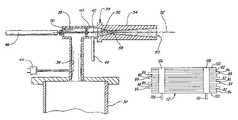
- FIG. 1is a generally schematic layout illustrating a kinetic spray system for performing the method of the present invention
- FIG. 2is an enlarged cross-sectional view of a kinetic spray nozzle used in the system
- FIG. 3is an exploded view of a cell of a non-thermal plasma reactor stack
- FIG. 4is an end view of a part of a non-thermal plasma reactor stack secured using the method of the present invention.
- FIG. 5is an end view of a part of a second embodiment of a non-thermal plasma reactor stack secured using the method of the present invention.
- System 10includes an enclosure 12 in which a support table 14 or other support means is located.
- a mounting panel 16 fixed to the table 14supports a work holder 18 capable of movement in three dimensions and able to support a suitable workpiece formed of a ceramic structure to be coated.
- the work holder 18is preferably designed to move a structure relative to a nozzle 34 of the system 10 , thereby controlling where the powder material is deposited on the structure.
- the enclosure 12includes surrounding walls having at least one air inlet, not shown, and an air outlet 20 connected by a suitable exhaust conduit 22 to a dust collector, not shown. During coating operations, the dust collector continually draws air from the enclosure 12 and collects any dust or particles contained in the exhaust air for subsequent disposal.
- the spray system 10further includes an air compressor 24 capable of supplying air pressure up to 3.4 MPa (500 psi) to a high pressure air ballast tank 26 .
- the air ballast tank 26is connected through a line 28 to both a high pressure powder feeder 30 and a separate air heater 32 .
- the air heater 32supplies high pressure heated air, the main gas described below, to a kinetic spray nozzle 34 .
- the pressure of the main gasgenerally is set at from 150 to 500 psi, more preferably from 300 to 400 psi.
- the high pressure powder feeder 30mixes particles of a spray powder with high pressure air and supplies the mixture to a supplemental inlet line 48 of the nozzle 34 . Preferably the particles are fed at a rate of from 20 to 80 grams per minute to the nozzle 34 .
- a computer control 35operates to control both the pressure of air supplied to the air heater 32 and the temperature of the heated main gas exiting the air heater 32 .
- the particles used in the present inventionare preferably electrically conductive materials including: copper, copper alloys, nickel, nickel alloys, aluminum, aluminum alloys, stainless steels, and mixtures of these materials.
- the powdersPreferably have nominal average particle sizes of from 60 to 106 microns and preferably from 60 to 90 microns.
- the main gas temperaturemay range from 600 to 1200 degrees Fahrenheit. With aluminum and its alloys the temperature preferably is around 600 degrees Fahrenheit, while the other materials preferably are sprayed at a main gas temperature of from 1000 to 1200 degrees Fahrenheit. Mixtures of the materials may be sprayed at from 600 to 1200 degrees Fahrenheit.
- FIG. 2is a cross-sectional view of the nozzle 34 and its connections to the air heater 32 and the powder feeder 30 .
- a main air passage 36connects the air heater 32 to the nozzle 34 .
- Passage 36connects with a premix chamber 38 that directs air through a flow straightener 40 and into a chamber 42 .
- Temperature and pressure of the air or other heated main gasare monitored by a gas inlet temperature thermocouple 44 in the passage 36 and a pressure sensor 46 connected to the chamber 42 .
- the main gashas a temperature that is always insufficient to cause melting within the nozzle 34 of any particles being sprayed.
- the main gas temperaturecan be well above the melt temperature of the particles.
- Main gas temperatures that are 5 to 7 fold above the melt temperature of the particleshave been used in the present system 10 .
- the main gas temperaturerange from 600 to 1200 degrees Fahrenheit depending on the material that is sprayed. What is necessary is that the temperature and exposure time to the main gas be selected such that the particles do not melt in the nozzle 34 .
- the temperature of the gasrapidly falls as it travels through the nozzle 34 .
- the temperature of the gas measured as it exits the nozzle 34is often at or below room temperature even when its initial temperature is above 1000° F.
- the mixture of high pressure air and coating powderis fed through the supplemental inlet line 48 to a powder injector tube 50 comprising a straight pipe having a predetermined inner diameter.
- the tube 50has a central axis 52 which is preferentially the same as the axis of the premix chamber 38 .
- the tube 50extends through the premix chamber 38 and the flow straightener 40 into the mixing chamber 42 .
- Chamber 42is in communication with a de Laval type supersonic nozzle 54 .
- the nozzle 54has a central axis 52 and an entrance cone 56 that decreases in diameter to a throat 58 .
- the entrance cone 56forms a converging region of the nozzle 54 . Downstream of the throat 58 is an exit end 60 and a diverging region is defined between the throat 58 and the exit end 60 .
- the largest diameter of the entrance cone 56may range from 10 to 6 millimeters, with 7.5 millimeters being preferred.
- the entrance cone 56narrows to the throat 58 .
- the throat 58may have a diameter of from 3.5 to 1.5 millimeters, with from 3 to 2 millimeters being preferred.
- the diverging region of the nozzle 54 from downstream of the throat 58 to the exit end 60may have a variety of shapes, but in a preferred embodiment it has a rectangular cross-sectional shape.
- the nozzle 54preferably has a rectangular shape with a long dimension of from 8 to 14 millimeters by a short dimension of from 2 to 6 millimeters.
- the powder injector tube 50supplies a particle powder mixture to the system 10 under a pressure in excess of the pressure of the heated main gas from the passage 36 .
- the nozzle 54produces an exit velocity of the entrained particles of from 300 meters per second to as high as 1200 meters per second. The entrained particles gain kinetic and thermal energy during their flow through this nozzle. It will be recognized by those of skill in the art that the temperature of the particles in the gas stream will vary depending on the particle size and the main gas temperature.
- the main gas temperatureis defined as the temperature of heated high-pressure gas at the inlet to the nozzle 54 .
- the particlesare never heated to their melting point, even upon impact, there is no change in the solid phase of the original particles due to transfer of kinetic and thermal energy, and therefore no change in their original physical properties.
- the particlesare always at a temperature below the main gas temperature.
- the particles exiting the nozzle 54are directed toward a surface of a substrate to coat it.
- the exit end 60 of the nozzle 54have a standoff distance from the surface to be coated of from 10 to 40 millimeters and most preferably from 10 to 20 millimeters.
- the particlesflatten into a nub-like structure with an aspect ratio of generally about 5 to 1.
- the kinetic sprayed particlestransfer substantially all of their kinetic and thermal energy to the substrate surface and stick if their yield stress has been exceeded.
- critical velocityis defined as the velocity where at it will adhere to a substrate when it strikes the substrate after exiting the nozzle 54 . This critical velocity is dependent on the material composition of the particle.
- the particlesIn general, harder materials must achieve a higher critical velocity before they adhere to a given substrate. It is not known at this time exactly what is the nature of the particle to substrate bond; however, it is believed that a portion of the bond is due to the particles plastically deforming upon striking the substrate. Preferably the particles have an average nominal diameter of from 60 to 90 microns.
- the nozzle 34be at an angle of from 0 to 45 degrees relative to a line drawn normal to the plane of the surface being coated, more preferably at an angle of from 15 to 25 degrees relative to the normal line.
- the work holder 18moves the structure past the nozzle 34 at a traverse speed of from 0.6 to 13 centimeters per second and more preferably at a traverse speed of from 0.6 to 7 centimeters per second.
- the present inventionwill be described with respect to its utilization to form electrical connections and secure multiple ceramic elements in a non-thermal plasma reactor, however the present invention can be used to secure any plurality of ceramic elements together.
- FIG. 3is an exploded view of a single cell 80 of a non-thermal plasma reactor.
- the cell 80includes a first ceramic element 82 , a second ceramic element 84 , a third ceramic element 86 , and a fourth ceramic element 88 .
- a pair of spacers 89are located between the second and third ceramic elements 84 , 86 .
- the first ceramic element 82includes a charge electrode 90 having a connector 92 .
- the second ceramic element 84includes a charge electrode 91 having a connector 93 .
- the third ceramic element 86includes a ground electrode 94 also having a connector 95 .
- the fourth ceramic element 88includes a ground electrode 97 also having a connector 99 .
- the connectors 92 , 93 of charge electrodes 90 and 91are offset from the connectors 95 and 99 of ground electrodes 94 and 97 for reasons explained below.
- the electrodes 90 , 91 , 94 , 97 and their connectors 92 , 93 , 95 , 99can comprise silver, tantalum, platinum, or any other conductive metal. They are applied to the ceramic elements 82 , 84 , 86 and 88 as is known in the art via any of a number of ways. These include painting, screen printing, and spray application. Each element 82 , 84 , 86 , and 88 has an edge 96 .
- the elements 82 , 84 , 86 , 88 and the spacers 89would need to be glued, clamped, and then fired to cure the glue. This was typically accomplished in the past by initially assembling the elements 82 , 84 , 86 , 88 and spacers 89 using high temperature dielectric paste, clamping, and then firing to transform the paste into a sintered glass/ceramic dielectric bond layer.
- FIG. 4an edge 96 view of an assembled non-thermal plasma reactor stack is shown at 100 .
- the componentsare as described above. Additionally, ceramic endplates 103 without electrodes are placed on either side of the stack 100 to insulate the stack 100 .
- the stack 100is assembled it is clamped into work holder 18 and held in place. Then using the spray parameters described above a first band 98 of electrically conductive material was applied by the kinetic spray process described herein.
- the first band 98replaces the previously used glue and serves to hold the elements of the stack 100 together.
- the first band 98is applied over the set of connectors 92 , 93 thereby electrically coupling all of the first and second element 82 , 84 electrodes 90 , 91 to each other.
- a second band 102 of electrically conductive materialwas applied by the kinetic spray process described herein.
- the second band 102also replaces the previously used glue and serves to hold the elements of the stack 100 together.
- the second band 102is applied over the other set of connectors 95 , 99 thereby electrically coupling all of the third and fourth element 86 , 88 electrodes 94 , 97 to each other.
- Stack 100may be further sprayed by the kinetic spray process described herein on the edge opposite edge 96 to further secure the elements together.
- the thickness of the first and second bands 98 , 102may vary from 1 millimeter to 2.5 centimeters depending on the stack 100 configuration.
- the material forming the bands 98 , 102is applied to the edge 96 at an angle of from 0 to 45 degrees relative to a line drawn normal to the edge 96 . More preferably the angle is from 15 to 25 degrees.
- the corrosion resistance layeris preferably form 20 microns to 1 millimeter in thickness.
- FIG. 5also shows a stack 112 as described in FIG. 4 with the difference that a first band 104 includes a conductive wire or ribbon 106 embedded in the band 104 while the kinetic spray process is occurring.
- the wire or ribbon 106can be directly connected to a power source.
- a second band 108includes a conductive ribbon or wire 110 that was embedded in the band 108 while the kinetic spray process was occurring.
Landscapes
- Physics & Mathematics (AREA)
- Engineering & Computer Science (AREA)
- Plasma & Fusion (AREA)
- Spectroscopy & Molecular Physics (AREA)
- Coating By Spraying Or Casting (AREA)
- Physical Or Chemical Processes And Apparatus (AREA)
- Other Surface Treatments For Metallic Materials (AREA)
Abstract
Description
Claims (28)
Priority Applications (1)
| Application Number | Priority Date | Filing Date | Title |
|---|---|---|---|
| US10/697,922US7335341B2 (en) | 2003-10-30 | 2003-10-30 | Method for securing ceramic structures and forming electrical connections on the same |
Applications Claiming Priority (1)
| Application Number | Priority Date | Filing Date | Title |
|---|---|---|---|
| US10/697,922US7335341B2 (en) | 2003-10-30 | 2003-10-30 | Method for securing ceramic structures and forming electrical connections on the same |
Publications (2)
| Publication Number | Publication Date |
|---|---|
| US20050100489A1 US20050100489A1 (en) | 2005-05-12 |
| US7335341B2true US7335341B2 (en) | 2008-02-26 |
Family
ID=34550495
Family Applications (1)
| Application Number | Title | Priority Date | Filing Date |
|---|---|---|---|
| US10/697,922Expired - Fee RelatedUS7335341B2 (en) | 2003-10-30 | 2003-10-30 | Method for securing ceramic structures and forming electrical connections on the same |
Country Status (1)
| Country | Link |
|---|---|
| US (1) | US7335341B2 (en) |
Cited By (10)
| Publication number | Priority date | Publication date | Assignee | Title |
|---|---|---|---|---|
| US20060192026A1 (en)* | 2005-02-25 | 2006-08-31 | Majed Noujaim | Combustion head for use with a flame spray apparatus |
| US20080271779A1 (en)* | 2007-05-04 | 2008-11-06 | H.C. Starck Inc. | Fine Grained, Non Banded, Refractory Metal Sputtering Targets with a Uniformly Random Crystallographic Orientation, Method for Making Such Film, and Thin Film Based Devices and Products Made Therefrom |
| US20100015467A1 (en)* | 2006-11-07 | 2010-01-21 | H.C. Starck Gmbh & Co., Kg | Method for coating a substrate and coated product |
| US20100055487A1 (en)* | 2005-05-05 | 2010-03-04 | H.C. Starck Gmbh | Method for coating a substrate surface and coated product |
| US20100061876A1 (en)* | 2008-09-09 | 2010-03-11 | H.C. Starck Inc. | Dynamic dehydriding of refractory metal powders |
| US20100272889A1 (en)* | 2006-10-03 | 2010-10-28 | H.C. Starch Inc. | Process for preparing metal powders having low oxygen content, powders so-produced and uses thereof |
| US8113413B2 (en) | 2006-12-13 | 2012-02-14 | H.C. Starck, Inc. | Protective metal-clad structures |
| US8703233B2 (en) | 2011-09-29 | 2014-04-22 | H.C. Starck Inc. | Methods of manufacturing large-area sputtering targets by cold spray |
| US10272543B2 (en)* | 2015-06-09 | 2019-04-30 | Sugino Machine Limited | Nozzle |
| US20210183617A1 (en)* | 2009-02-08 | 2021-06-17 | Atmospheric Plasma Solutions, Inc. | Plasma source and method for removing materials from substrates utilizing pressure waves |
Citations (96)
| Publication number | Priority date | Publication date | Assignee | Title |
|---|---|---|---|---|
| US2861900A (en) | 1955-05-02 | 1958-11-25 | Union Carbide Corp | Jet plating of high melting point materials |
| US3100724A (en) | 1958-09-22 | 1963-08-13 | Microseal Products Inc | Device for treating the surface of a workpiece |
| US3876456A (en) | 1973-03-16 | 1975-04-08 | Olin Corp | Catalyst for the reduction of automobile exhaust gases |
| US3993411A (en) | 1973-06-01 | 1976-11-23 | General Electric Company | Bonds between metal and a non-metallic substrate |
| US3996398A (en) | 1972-11-08 | 1976-12-07 | Societe De Fabrication D'elements Catalytiques | Method of spray-coating with metal alloys |
| JPS5531161A (en) | 1978-08-26 | 1980-03-05 | Nikken Toso Kogyo Kk | Coating film for decomposing fat and oil |
| US4263335A (en) | 1978-07-26 | 1981-04-21 | Ppg Industries, Inc. | Airless spray method for depositing electroconductive tin oxide coatings |
| US4416421A (en) | 1980-10-09 | 1983-11-22 | Browning Engineering Corporation | Highly concentrated supersonic liquified material flame spray method and apparatus |
| US4606495A (en) | 1983-12-22 | 1986-08-19 | United Technologies Corporation | Uniform braze application process |
| JPS61249541A (en) | 1985-04-26 | 1986-11-06 | Matsushita Electric Ind Co Ltd | oxidation catalyst |
| US4891275A (en) | 1982-10-29 | 1990-01-02 | Norsk Hydro A.S. | Aluminum shapes coated with brazing material and process of coating |
| US4939022A (en) | 1988-04-04 | 1990-07-03 | Delco Electronics Corporation | Electrical conductors |
| JPH04180770A (en) | 1990-11-15 | 1992-06-26 | Tdk Corp | Sterilizing/deodorizing device |
| JPH04243524A (en) | 1991-01-25 | 1992-08-31 | Matsushita Electric Ind Co Ltd | Trap for purifying diesel exhaust gas |
| US5187021A (en) | 1989-02-08 | 1993-02-16 | Diamond Fiber Composites, Inc. | Coated and whiskered fibers for use in composite materials |
| US5217746A (en) | 1990-12-13 | 1993-06-08 | Fisher-Barton Inc. | Method for minimizing decarburization and other high temperature oxygen reactions in a plasma sprayed material |
| US5271965A (en) | 1991-01-16 | 1993-12-21 | Browning James A | Thermal spray method utilizing in-transit powder particle temperatures below their melting point |
| DE4236911C1 (en) | 1992-10-31 | 1993-12-23 | Osu Maschinenbau Gmbh | Thermal spray coating of metallic surfaces - by spraying powdered mixt. of ceramic, metallic or carbide-like material in gas stream via jets onto pre-blasted surfaces |
| US5302414A (en) | 1990-05-19 | 1994-04-12 | Anatoly Nikiforovich Papyrin | Gas-dynamic spraying method for applying a coating |
| US5308463A (en) | 1991-09-13 | 1994-05-03 | Hoechst Aktiengesellschaft | Preparation of a firm bond between copper layers and aluminum oxide ceramic without use of coupling agents |
| US5328751A (en) | 1991-07-12 | 1994-07-12 | Kabushiki Kaisha Toshiba | Ceramic circuit board with a curved lead terminal |
| US5340015A (en) | 1993-03-22 | 1994-08-23 | Westinghouse Electric Corp. | Method for applying brazing filler metals |
| US5362523A (en) | 1991-09-05 | 1994-11-08 | Technalum Research, Inc. | Method for the production of compositionally graded coatings by plasma spraying powders |
| US5395679A (en) | 1993-03-29 | 1995-03-07 | Delco Electronics Corp. | Ultra-thick thick films for thermal management and current carrying capabilities in hybrid circuits |
| US5424101A (en) | 1994-10-24 | 1995-06-13 | General Motors Corporation | Method of making metallized epoxy tools |
| US5464146A (en) | 1994-09-29 | 1995-11-07 | Ford Motor Company | Thin film brazing of aluminum shapes |
| US5465627A (en) | 1991-07-29 | 1995-11-14 | Magnetoelastic Devices, Inc. | Circularly magnetized non-contact torque sensor and method for measuring torque using same |
| US5476725A (en) | 1991-03-18 | 1995-12-19 | Aluminum Company Of America | Clad metallurgical products and methods of manufacture |
| US5493921A (en) | 1993-09-29 | 1996-02-27 | Daimler-Benz Ag | Sensor for non-contact torque measurement on a shaft as well as a measurement layer for such a sensor |
| US5520059A (en) | 1991-07-29 | 1996-05-28 | Magnetoelastic Devices, Inc. | Circularly magnetized non-contact torque sensor and method for measuring torque using same |
| US5525570A (en) | 1991-03-09 | 1996-06-11 | Forschungszentrum Julich Gmbh | Process for producing a catalyst layer on a carrier and a catalyst produced therefrom |
| US5527627A (en) | 1993-03-29 | 1996-06-18 | Delco Electronics Corp. | Ink composition for an ultra-thick thick film for thermal management of a hybrid circuit |
| US5585574A (en) | 1993-02-02 | 1996-12-17 | Mitsubishi Materials Corporation | Shaft having a magnetostrictive torque sensor and a method for making same |
| US5593740A (en) | 1995-01-17 | 1997-01-14 | Synmatix Corporation | Method and apparatus for making carbon-encapsulated ultrafine metal particles |
| US5648123A (en) | 1992-04-02 | 1997-07-15 | Hoechst Aktiengesellschaft | Process for producing a strong bond between copper layers and ceramic |
| US5683615A (en) | 1996-06-13 | 1997-11-04 | Lord Corporation | Magnetorheological fluid |
| US5708216A (en) | 1991-07-29 | 1998-01-13 | Magnetoelastic Devices, Inc. | Circularly magnetized non-contact torque sensor and method for measuring torque using same |
| US5725023A (en) | 1995-02-21 | 1998-03-10 | Lectron Products, Inc. | Power steering system and control valve |
| WO1998022639A1 (en) | 1996-11-13 | 1998-05-28 | O.O.O. Obninsky Tsentr Poroshkovogo Napylenia | Apparatus for gas-dynamic coating |
| US5795626A (en) | 1995-04-28 | 1998-08-18 | Innovative Technology Inc. | Coating or ablation applicator with a debris recovery attachment |
| US5854966A (en) | 1995-05-24 | 1998-12-29 | Virginia Tech Intellectual Properties, Inc. | Method of producing composite materials including metallic matrix composite reinforcements |
| US5875626A (en) | 1996-09-27 | 1999-03-02 | Sonoco Products Company | Adapter for rotatably supporting a yarn carrier in a winding assembly of a yarn processing machine |
| US5889215A (en) | 1996-12-04 | 1999-03-30 | Philips Electronics North America Corporation | Magnetoelastic torque sensor with shielding flux guide |
| US5894054A (en) | 1997-01-09 | 1999-04-13 | Ford Motor Company | Aluminum components coated with zinc-antimony alloy for manufacturing assemblies by CAB brazing |
| US5907105A (en) | 1997-07-21 | 1999-05-25 | General Motors Corporation | Magnetostrictive torque sensor utilizing RFe2 -based composite materials |
| US5907761A (en) | 1994-03-28 | 1999-05-25 | Mitsubishi Aluminum Co., Ltd. | Brazing composition, aluminum material provided with the brazing composition and heat exchanger |
| US5952056A (en) | 1994-09-24 | 1999-09-14 | Sprayform Holdings Limited | Metal forming process |
| US5965193A (en) | 1994-04-11 | 1999-10-12 | Dowa Mining Co., Ltd. | Process for preparing a ceramic electronic circuit board and process for preparing aluminum or aluminum alloy bonded ceramic material |
| US5989310A (en) | 1997-11-25 | 1999-11-23 | Aluminum Company Of America | Method of forming ceramic particles in-situ in metal |
| US5993565A (en) | 1996-07-01 | 1999-11-30 | General Motors Corporation | Magnetostrictive composites |
| US6033622A (en) | 1998-09-21 | 2000-03-07 | The United States Of America As Represented By The Secretary Of The Air Force | Method for making metal matrix composites |
| US6047605A (en) | 1997-10-21 | 2000-04-11 | Magna-Lastic Devices, Inc. | Collarless circularly magnetized torque transducer having two phase shaft and method for measuring torque using same |
| US6051045A (en) | 1996-01-16 | 2000-04-18 | Ford Global Technologies, Inc. | Metal-matrix composites |
| US6051277A (en) | 1996-02-16 | 2000-04-18 | Nils Claussen | Al2 O3 composites and methods for their production |
| US6074737A (en) | 1996-03-05 | 2000-06-13 | Sprayform Holdings Limited | Filling porosity or voids in articles formed in spray deposition processes |
| US6098741A (en) | 1999-01-28 | 2000-08-08 | Eaton Corporation | Controlled torque steering system and method |
| US6119667A (en) | 1999-07-22 | 2000-09-19 | Delphi Technologies, Inc. | Integrated spark plug ignition coil with pressure sensor for an internal combustion engine |
| US6129948A (en) | 1996-12-23 | 2000-10-10 | National Center For Manufacturing Sciences | Surface modification to achieve improved electrical conductivity |
| US6139913A (en) | 1999-06-29 | 2000-10-31 | National Center For Manufacturing Sciences | Kinetic spray coating method and apparatus |
| US6149736A (en) | 1995-12-05 | 2000-11-21 | Honda Giken Kogyo Kabushiki Kaisha | Magnetostructure material, and process for producing the same |
| US6159430A (en) | 1998-12-21 | 2000-12-12 | Delphi Technologies, Inc. | Catalytic converter |
| US6189663B1 (en) | 1998-06-08 | 2001-02-20 | General Motors Corporation | Spray coatings for suspension damper rods |
| DE19959515A1 (en) | 1999-12-09 | 2001-06-13 | Dacs Dvorak Advanced Coating S | Process for plastic coating by means of a spraying process, a device therefor and the use of the layer |
| US6261703B1 (en) | 1997-05-26 | 2001-07-17 | Sumitomo Electric Industries, Ltd. | Copper circuit junction substrate and method of producing the same |
| US6283859B1 (en) | 1998-11-10 | 2001-09-04 | Lord Corporation | Magnetically-controllable, active haptic interface system and apparatus |
| US6289748B1 (en) | 1999-11-23 | 2001-09-18 | Delphi Technologies, Inc. | Shaft torque sensor with no air gap |
| EP1160348A2 (en) | 2000-05-22 | 2001-12-05 | Praxair S.T. Technology, Inc. | Process for producing graded coated articles |
| US6338827B1 (en) | 1999-06-29 | 2002-01-15 | Delphi Technologies, Inc. | Stacked shape plasma reactor design for treating auto emissions |
| DE10037212A1 (en) | 2000-07-07 | 2002-01-17 | Linde Gas Ag | Plastic surfaces with a thermally sprayed coating and process for their production |
| US6344237B1 (en) | 1999-03-05 | 2002-02-05 | Alcoa Inc. | Method of depositing flux or flux and metal onto a metal brazing substrate |
| US6374664B1 (en) | 2000-01-21 | 2002-04-23 | Delphi Technologies, Inc. | Rotary position transducer and method |
| US20020071906A1 (en) | 2000-12-13 | 2002-06-13 | Rusch William P. | Method and device for applying a coating |
| US20020073982A1 (en) | 2000-12-16 | 2002-06-20 | Shaikh Furqan Zafar | Gas-dynamic cold spray lining for aluminum engine block cylinders |
| US6422360B1 (en) | 2001-03-28 | 2002-07-23 | Delphi Technologies, Inc. | Dual mode suspension damper controlled by magnetostrictive element |
| US6424896B1 (en) | 2000-03-30 | 2002-07-23 | Delphi Technologies, Inc. | Steering column differential angle position sensor |
| US20020102360A1 (en) | 2001-01-30 | 2002-08-01 | Siemens Westinghouse Power Corporation | Thermal barrier coating applied with cold spray technique |
| US20020110682A1 (en) | 2000-12-12 | 2002-08-15 | Brogan Jeffrey A. | Non-skid coating and method of forming the same |
| US20020112549A1 (en) | 2000-11-21 | 2002-08-22 | Abdolreza Cheshmehdoost | Torque sensing apparatus and method |
| US6442039B1 (en) | 1999-12-03 | 2002-08-27 | Delphi Technologies, Inc. | Metallic microstructure springs and method of making same |
| US6446857B1 (en) | 2001-05-31 | 2002-09-10 | Delphi Technologies, Inc. | Method for brazing fittings to pipes |
| US6465039B1 (en) | 2001-08-13 | 2002-10-15 | General Motors Corporation | Method of forming a magnetostrictive composite coating |
| US6485852B1 (en) | 2000-01-07 | 2002-11-26 | Delphi Technologies, Inc. | Integrated fuel reformation and thermal management system for solid oxide fuel cell systems |
| US6488115B1 (en) | 2001-08-01 | 2002-12-03 | Delphi Technologies, Inc. | Apparatus and method for steering a vehicle |
| DE10126100A1 (en) | 2001-05-29 | 2002-12-05 | Linde Ag | Production of a coating or a molded part comprises injecting powdered particles in a gas stream only in the divergent section of a Laval nozzle, and applying the particles at a specified speed |
| US20020182311A1 (en) | 2001-05-30 | 2002-12-05 | Franco Leonardi | Method of manufacturing electromagnetic devices using kinetic spray |
| US6511135B2 (en) | 1999-12-14 | 2003-01-28 | Delphi Technologies, Inc. | Disk brake mounting bracket and high gain torque sensor |
| WO2003009934A1 (en) | 2001-07-24 | 2003-02-06 | Honda Giken Kabushiki Kaisha | Metal oxide and noble metal catalyst coatings |
| US20030039856A1 (en) | 2001-08-15 | 2003-02-27 | Gillispie Bryan A. | Product and method of brazing using kinetic sprayed coatings |
| US6537507B2 (en) | 2000-02-23 | 2003-03-25 | Delphi Technologies, Inc. | Non-thermal plasma reactor design and single structural dielectric barrier |
| US6551734B1 (en) | 2000-10-27 | 2003-04-22 | Delphi Technologies, Inc. | Solid oxide fuel cell having a monolithic heat exchanger and method for managing thermal energy flow of the fuel cell |
| WO2002052064A9 (en) | 2000-08-25 | 2003-07-24 | Obschestvo S Ogranichennoi Otv | Coating method |
| US6615488B2 (en) | 2002-02-04 | 2003-09-09 | Delphi Technologies, Inc. | Method of forming heat exchanger tube |
| US6623796B1 (en) | 2002-04-05 | 2003-09-23 | Delphi Technologies, Inc. | Method of producing a coating using a kinetic spray process with large particles and nozzles for the same |
| US6623704B1 (en) | 2000-02-22 | 2003-09-23 | Delphi Technologies, Inc. | Apparatus and method for manufacturing a catalytic converter |
| US20030190414A1 (en) | 2002-04-05 | 2003-10-09 | Van Steenkiste Thomas Hubert | Low pressure powder injection method and system for a kinetic spray process |
| US20030219542A1 (en) | 2002-05-25 | 2003-11-27 | Ewasyshyn Frank J. | Method of forming dense coatings by powder spraying |
- 2003
- 2003-10-30USUS10/697,922patent/US7335341B2/ennot_activeExpired - Fee Related
Patent Citations (106)
| Publication number | Priority date | Publication date | Assignee | Title |
|---|---|---|---|---|
| US2861900A (en) | 1955-05-02 | 1958-11-25 | Union Carbide Corp | Jet plating of high melting point materials |
| US3100724A (en) | 1958-09-22 | 1963-08-13 | Microseal Products Inc | Device for treating the surface of a workpiece |
| US3996398A (en) | 1972-11-08 | 1976-12-07 | Societe De Fabrication D'elements Catalytiques | Method of spray-coating with metal alloys |
| US3876456A (en) | 1973-03-16 | 1975-04-08 | Olin Corp | Catalyst for the reduction of automobile exhaust gases |
| US3993411A (en) | 1973-06-01 | 1976-11-23 | General Electric Company | Bonds between metal and a non-metallic substrate |
| US4263335A (en) | 1978-07-26 | 1981-04-21 | Ppg Industries, Inc. | Airless spray method for depositing electroconductive tin oxide coatings |
| JPS5531161A (en) | 1978-08-26 | 1980-03-05 | Nikken Toso Kogyo Kk | Coating film for decomposing fat and oil |
| US4416421A (en) | 1980-10-09 | 1983-11-22 | Browning Engineering Corporation | Highly concentrated supersonic liquified material flame spray method and apparatus |
| US4891275A (en) | 1982-10-29 | 1990-01-02 | Norsk Hydro A.S. | Aluminum shapes coated with brazing material and process of coating |
| US4606495A (en) | 1983-12-22 | 1986-08-19 | United Technologies Corporation | Uniform braze application process |
| JPS61249541A (en) | 1985-04-26 | 1986-11-06 | Matsushita Electric Ind Co Ltd | oxidation catalyst |
| US4939022A (en) | 1988-04-04 | 1990-07-03 | Delco Electronics Corporation | Electrical conductors |
| US5187021A (en) | 1989-02-08 | 1993-02-16 | Diamond Fiber Composites, Inc. | Coated and whiskered fibers for use in composite materials |
| US5302414B1 (en) | 1990-05-19 | 1997-02-25 | Anatoly N Papyrin | Gas-dynamic spraying method for applying a coating |
| US5302414A (en) | 1990-05-19 | 1994-04-12 | Anatoly Nikiforovich Papyrin | Gas-dynamic spraying method for applying a coating |
| JPH04180770A (en) | 1990-11-15 | 1992-06-26 | Tdk Corp | Sterilizing/deodorizing device |
| US5217746A (en) | 1990-12-13 | 1993-06-08 | Fisher-Barton Inc. | Method for minimizing decarburization and other high temperature oxygen reactions in a plasma sprayed material |
| US5271965A (en) | 1991-01-16 | 1993-12-21 | Browning James A | Thermal spray method utilizing in-transit powder particle temperatures below their melting point |
| JPH04243524A (en) | 1991-01-25 | 1992-08-31 | Matsushita Electric Ind Co Ltd | Trap for purifying diesel exhaust gas |
| US5525570A (en) | 1991-03-09 | 1996-06-11 | Forschungszentrum Julich Gmbh | Process for producing a catalyst layer on a carrier and a catalyst produced therefrom |
| US5476725A (en) | 1991-03-18 | 1995-12-19 | Aluminum Company Of America | Clad metallurgical products and methods of manufacture |
| US5328751A (en) | 1991-07-12 | 1994-07-12 | Kabushiki Kaisha Toshiba | Ceramic circuit board with a curved lead terminal |
| US5708216A (en) | 1991-07-29 | 1998-01-13 | Magnetoelastic Devices, Inc. | Circularly magnetized non-contact torque sensor and method for measuring torque using same |
| US6490934B2 (en) | 1991-07-29 | 2002-12-10 | Magnetoelastic Devices, Inc. | Circularly magnetized non-contact torque sensor and method for measuring torque using the same |
| US5887335A (en) | 1991-07-29 | 1999-03-30 | Magna-Lastic Devices, Inc. | Method of producing a circularly magnetized non-contact torque sensor |
| US5465627A (en) | 1991-07-29 | 1995-11-14 | Magnetoelastic Devices, Inc. | Circularly magnetized non-contact torque sensor and method for measuring torque using same |
| US5520059A (en) | 1991-07-29 | 1996-05-28 | Magnetoelastic Devices, Inc. | Circularly magnetized non-contact torque sensor and method for measuring torque using same |
| US5706572A (en) | 1991-07-29 | 1998-01-13 | Magnetoelastic Devices, Inc. | Method for producing a circularly magnetized non-contact torque sensor |
| US5362523A (en) | 1991-09-05 | 1994-11-08 | Technalum Research, Inc. | Method for the production of compositionally graded coatings by plasma spraying powders |
| US5308463A (en) | 1991-09-13 | 1994-05-03 | Hoechst Aktiengesellschaft | Preparation of a firm bond between copper layers and aluminum oxide ceramic without use of coupling agents |
| US5648123A (en) | 1992-04-02 | 1997-07-15 | Hoechst Aktiengesellschaft | Process for producing a strong bond between copper layers and ceramic |
| DE4236911C1 (en) | 1992-10-31 | 1993-12-23 | Osu Maschinenbau Gmbh | Thermal spray coating of metallic surfaces - by spraying powdered mixt. of ceramic, metallic or carbide-like material in gas stream via jets onto pre-blasted surfaces |
| US5585574A (en) | 1993-02-02 | 1996-12-17 | Mitsubishi Materials Corporation | Shaft having a magnetostrictive torque sensor and a method for making same |
| US5340015A (en) | 1993-03-22 | 1994-08-23 | Westinghouse Electric Corp. | Method for applying brazing filler metals |
| US5527627A (en) | 1993-03-29 | 1996-06-18 | Delco Electronics Corp. | Ink composition for an ultra-thick thick film for thermal management of a hybrid circuit |
| US5395679A (en) | 1993-03-29 | 1995-03-07 | Delco Electronics Corp. | Ultra-thick thick films for thermal management and current carrying capabilities in hybrid circuits |
| US5493921A (en) | 1993-09-29 | 1996-02-27 | Daimler-Benz Ag | Sensor for non-contact torque measurement on a shaft as well as a measurement layer for such a sensor |
| US5907761A (en) | 1994-03-28 | 1999-05-25 | Mitsubishi Aluminum Co., Ltd. | Brazing composition, aluminum material provided with the brazing composition and heat exchanger |
| US5965193A (en) | 1994-04-11 | 1999-10-12 | Dowa Mining Co., Ltd. | Process for preparing a ceramic electronic circuit board and process for preparing aluminum or aluminum alloy bonded ceramic material |
| US5952056A (en) | 1994-09-24 | 1999-09-14 | Sprayform Holdings Limited | Metal forming process |
| US5464146A (en) | 1994-09-29 | 1995-11-07 | Ford Motor Company | Thin film brazing of aluminum shapes |
| US5424101A (en) | 1994-10-24 | 1995-06-13 | General Motors Corporation | Method of making metallized epoxy tools |
| US5593740A (en) | 1995-01-17 | 1997-01-14 | Synmatix Corporation | Method and apparatus for making carbon-encapsulated ultrafine metal particles |
| US5725023A (en) | 1995-02-21 | 1998-03-10 | Lectron Products, Inc. | Power steering system and control valve |
| US5795626A (en) | 1995-04-28 | 1998-08-18 | Innovative Technology Inc. | Coating or ablation applicator with a debris recovery attachment |
| US5854966A (en) | 1995-05-24 | 1998-12-29 | Virginia Tech Intellectual Properties, Inc. | Method of producing composite materials including metallic matrix composite reinforcements |
| US6149736A (en) | 1995-12-05 | 2000-11-21 | Honda Giken Kogyo Kabushiki Kaisha | Magnetostructure material, and process for producing the same |
| US6051045A (en) | 1996-01-16 | 2000-04-18 | Ford Global Technologies, Inc. | Metal-matrix composites |
| US6051277A (en) | 1996-02-16 | 2000-04-18 | Nils Claussen | Al2 O3 composites and methods for their production |
| US6074737A (en) | 1996-03-05 | 2000-06-13 | Sprayform Holdings Limited | Filling porosity or voids in articles formed in spray deposition processes |
| US5683615A (en) | 1996-06-13 | 1997-11-04 | Lord Corporation | Magnetorheological fluid |
| US5993565A (en) | 1996-07-01 | 1999-11-30 | General Motors Corporation | Magnetostrictive composites |
| US5875626A (en) | 1996-09-27 | 1999-03-02 | Sonoco Products Company | Adapter for rotatably supporting a yarn carrier in a winding assembly of a yarn processing machine |
| WO1998022639A1 (en) | 1996-11-13 | 1998-05-28 | O.O.O. Obninsky Tsentr Poroshkovogo Napylenia | Apparatus for gas-dynamic coating |
| US6402050B1 (en) | 1996-11-13 | 2002-06-11 | Alexandr Ivanovich Kashirin | Apparatus for gas-dynamic coating |
| US5889215A (en) | 1996-12-04 | 1999-03-30 | Philips Electronics North America Corporation | Magnetoelastic torque sensor with shielding flux guide |
| US6129948A (en) | 1996-12-23 | 2000-10-10 | National Center For Manufacturing Sciences | Surface modification to achieve improved electrical conductivity |
| US5894054A (en) | 1997-01-09 | 1999-04-13 | Ford Motor Company | Aluminum components coated with zinc-antimony alloy for manufacturing assemblies by CAB brazing |
| US6261703B1 (en) | 1997-05-26 | 2001-07-17 | Sumitomo Electric Industries, Ltd. | Copper circuit junction substrate and method of producing the same |
| US5907105A (en) | 1997-07-21 | 1999-05-25 | General Motors Corporation | Magnetostrictive torque sensor utilizing RFe2 -based composite materials |
| US6047605A (en) | 1997-10-21 | 2000-04-11 | Magna-Lastic Devices, Inc. | Collarless circularly magnetized torque transducer having two phase shaft and method for measuring torque using same |
| US6553847B2 (en) | 1997-10-21 | 2003-04-29 | Magna-Lastic Devices, Inc. | Collarless circularly magnetized torque transducer and method for measuring torque using the same |
| US6260423B1 (en) | 1997-10-21 | 2001-07-17 | Ivan J. Garshelis | Collarless circularly magnetized torque transducer and method for measuring torque using same |
| US6145387A (en) | 1997-10-21 | 2000-11-14 | Magna-Lastic Devices, Inc | Collarless circularly magnetized torque transducer and method for measuring torque using same |
| US5989310A (en) | 1997-11-25 | 1999-11-23 | Aluminum Company Of America | Method of forming ceramic particles in-situ in metal |
| US6189663B1 (en) | 1998-06-08 | 2001-02-20 | General Motors Corporation | Spray coatings for suspension damper rods |
| US6033622A (en) | 1998-09-21 | 2000-03-07 | The United States Of America As Represented By The Secretary Of The Air Force | Method for making metal matrix composites |
| US6283859B1 (en) | 1998-11-10 | 2001-09-04 | Lord Corporation | Magnetically-controllable, active haptic interface system and apparatus |
| US6159430A (en) | 1998-12-21 | 2000-12-12 | Delphi Technologies, Inc. | Catalytic converter |
| US6098741A (en) | 1999-01-28 | 2000-08-08 | Eaton Corporation | Controlled torque steering system and method |
| US6344237B1 (en) | 1999-03-05 | 2002-02-05 | Alcoa Inc. | Method of depositing flux or flux and metal onto a metal brazing substrate |
| US6139913A (en) | 1999-06-29 | 2000-10-31 | National Center For Manufacturing Sciences | Kinetic spray coating method and apparatus |
| US6283386B1 (en) | 1999-06-29 | 2001-09-04 | National Center For Manufacturing Sciences | Kinetic spray coating apparatus |
| US6338827B1 (en) | 1999-06-29 | 2002-01-15 | Delphi Technologies, Inc. | Stacked shape plasma reactor design for treating auto emissions |
| US6119667A (en) | 1999-07-22 | 2000-09-19 | Delphi Technologies, Inc. | Integrated spark plug ignition coil with pressure sensor for an internal combustion engine |
| US6289748B1 (en) | 1999-11-23 | 2001-09-18 | Delphi Technologies, Inc. | Shaft torque sensor with no air gap |
| US6442039B1 (en) | 1999-12-03 | 2002-08-27 | Delphi Technologies, Inc. | Metallic microstructure springs and method of making same |
| DE19959515A1 (en) | 1999-12-09 | 2001-06-13 | Dacs Dvorak Advanced Coating S | Process for plastic coating by means of a spraying process, a device therefor and the use of the layer |
| US6511135B2 (en) | 1999-12-14 | 2003-01-28 | Delphi Technologies, Inc. | Disk brake mounting bracket and high gain torque sensor |
| US6485852B1 (en) | 2000-01-07 | 2002-11-26 | Delphi Technologies, Inc. | Integrated fuel reformation and thermal management system for solid oxide fuel cell systems |
| US6374664B1 (en) | 2000-01-21 | 2002-04-23 | Delphi Technologies, Inc. | Rotary position transducer and method |
| US6623704B1 (en) | 2000-02-22 | 2003-09-23 | Delphi Technologies, Inc. | Apparatus and method for manufacturing a catalytic converter |
| US6537507B2 (en) | 2000-02-23 | 2003-03-25 | Delphi Technologies, Inc. | Non-thermal plasma reactor design and single structural dielectric barrier |
| US6424896B1 (en) | 2000-03-30 | 2002-07-23 | Delphi Technologies, Inc. | Steering column differential angle position sensor |
| EP1160348A2 (en) | 2000-05-22 | 2001-12-05 | Praxair S.T. Technology, Inc. | Process for producing graded coated articles |
| DE10037212A1 (en) | 2000-07-07 | 2002-01-17 | Linde Gas Ag | Plastic surfaces with a thermally sprayed coating and process for their production |
| WO2002052064A9 (en) | 2000-08-25 | 2003-07-24 | Obschestvo S Ogranichennoi Otv | Coating method |
| US6551734B1 (en) | 2000-10-27 | 2003-04-22 | Delphi Technologies, Inc. | Solid oxide fuel cell having a monolithic heat exchanger and method for managing thermal energy flow of the fuel cell |
| US20020112549A1 (en) | 2000-11-21 | 2002-08-22 | Abdolreza Cheshmehdoost | Torque sensing apparatus and method |
| US20020110682A1 (en) | 2000-12-12 | 2002-08-15 | Brogan Jeffrey A. | Non-skid coating and method of forming the same |
| US20020071906A1 (en) | 2000-12-13 | 2002-06-13 | Rusch William P. | Method and device for applying a coating |
| US20020073982A1 (en) | 2000-12-16 | 2002-06-20 | Shaikh Furqan Zafar | Gas-dynamic cold spray lining for aluminum engine block cylinders |
| US20020102360A1 (en) | 2001-01-30 | 2002-08-01 | Siemens Westinghouse Power Corporation | Thermal barrier coating applied with cold spray technique |
| EP1245854A2 (en) | 2001-03-28 | 2002-10-02 | Delphi Technologies, Inc. | Dual mode suspension damper controlled by magnetostrictive element |
| US6422360B1 (en) | 2001-03-28 | 2002-07-23 | Delphi Technologies, Inc. | Dual mode suspension damper controlled by magnetostrictive element |
| DE10126100A1 (en) | 2001-05-29 | 2002-12-05 | Linde Ag | Production of a coating or a molded part comprises injecting powdered particles in a gas stream only in the divergent section of a Laval nozzle, and applying the particles at a specified speed |
| US20020182311A1 (en) | 2001-05-30 | 2002-12-05 | Franco Leonardi | Method of manufacturing electromagnetic devices using kinetic spray |
| US6446857B1 (en) | 2001-05-31 | 2002-09-10 | Delphi Technologies, Inc. | Method for brazing fittings to pipes |
| WO2003009934A1 (en) | 2001-07-24 | 2003-02-06 | Honda Giken Kabushiki Kaisha | Metal oxide and noble metal catalyst coatings |
| US6488115B1 (en) | 2001-08-01 | 2002-12-03 | Delphi Technologies, Inc. | Apparatus and method for steering a vehicle |
| US6465039B1 (en) | 2001-08-13 | 2002-10-15 | General Motors Corporation | Method of forming a magnetostrictive composite coating |
| US20030039856A1 (en) | 2001-08-15 | 2003-02-27 | Gillispie Bryan A. | Product and method of brazing using kinetic sprayed coatings |
| US6615488B2 (en) | 2002-02-04 | 2003-09-09 | Delphi Technologies, Inc. | Method of forming heat exchanger tube |
| US6623796B1 (en) | 2002-04-05 | 2003-09-23 | Delphi Technologies, Inc. | Method of producing a coating using a kinetic spray process with large particles and nozzles for the same |
| US20030190414A1 (en) | 2002-04-05 | 2003-10-09 | Van Steenkiste Thomas Hubert | Low pressure powder injection method and system for a kinetic spray process |
| US20030219542A1 (en) | 2002-05-25 | 2003-11-27 | Ewasyshyn Frank J. | Method of forming dense coatings by powder spraying |
Non-Patent Citations (37)
| Title |
|---|
| Alkhimov, et al; A Method of "Cold" Gas-Dynamic Deposition; Sov. Phys. Kokl. 36(Dec. 12, 1990; pp. 1047-1049. |
| Boley, et al; The Effects of Heat Treatment on the Magnetic Behavior of Ring-Type Magnetoelastic Torque Sensors; Proceedings of Sicon '01; Nov. 2001. |
| Cetek 930580 Compass Sensor, Specifications, Jun. 1997. |
| Davis, et al; Thermal Conductivity of Metal-Matrix Composlites; J.Appl. Phys. 77 (10), May 15, 1995; pp. 4494-4960. |
| Derac Son, A New Type of Fluxgate Magnetometer Using Apparent Coercive Field Strength Measurement, IEEE Transactions on Magnetics, vol. 25, No. 5, Sep. 1989, pp. 3420-3422. |
| Dykhuizen et al; Gas Dynamic Principles of Cold Spray; Journal of Thermal Spray Technology; Jun. 1998; pp. 205-212. |
| Dykhuizen, et al.; Gas Dynamic Principles of Cold Spray; Journal of Thermal Spray Technology; Jun. 1998; pp. 205-212. |
| Dykuizen, et al; Impact of High Velocity Cold Spray Particles; in Journal of Thermal Spray Technology 8(4); 1999; pp. 559-564. |
| European Search Report dated Jan. 29, 2004 and it's Annex. |
| Geyger, Basic Principles Characteristics and Applications, Magnetic Amplifier Circuits, 1954, pp. 219-232. |
| Henriksen, et al; Digital Detection and Feedback Fluxgate Magnetometer, Meas. Sci. Technol. 7 (1996) pp. 897-903. |
| Hoton How, et al; Development of High-Sensitivity Fluxgate Magnetometer Using Single-Crystal Yttrium Iron Garnet Thick Film as the Core Material, ElectroMagnnetic Applications, Inc.. |
| How, et al; Generation of High-Order Harmonics in Insulator Magnetic Fluxgate Sensor Cores; IEEE Transactions on Magnetics, vol. 37, No. 4, Jul. 2001, pp. 2448-2450. |
| I.J. Garshelis, et al; A Magnetoelastic Torque Transducer Utilizing a Ring Divided into Two Oppositely Polarized Circumferential Regions; MMM 1995; Paper No. BB-08. |
| I.J. Garshelis, et al; Development of a Non-Contact Torque Transducer for Electric Power Steering Systems; SAE Paper No. 920707; 1992; pp. 173-182. |
| Ibrahim et al; Particulate Reinforced Metal Matrix Composites-A Review; Journal of Matrials Science 26; 1991, pp. 1137-1156. |
| Ibrahim, et al; Particulate Reinforced Metal Matrix Composites-A Review; Journal of Materials Science 26; 1991, pp. 1137-1156. |
| J.E. Snyder, et al; Low Coercivity Magnetostrictive Material with Giant Piezomagnetic d33, Abstract Submitted for the MAR99 Meeting of the American Physical Society, 1998. |
| Johnson et al; Diamond/Al metal matrix composites formed by the pressureless metal infiltration process; J. Mater, Res., vol. 8, No. 5, May 1993; pp. 11691173. |
| LEC Manufacturing and Engineering Capabilities; Lanxide Electronic Components, Inc. |
| Liu, et al; Recent Development in the Fabrication of Metal Matrix-Particulate Composites Using Powder Metallurgy Techniques; in Journal of Material Science 29; 1994; pp. 1999-2007; National University of Singapore, Japan. |
| McCune et al; An Exploration of the Cold Gas-Dynamic Spray Method For Several Materials Systems. |
| McCune, al; Characterization of Copper and Steel Coatings Made by the Cold Gas-Dynamic Spray Method; National Thermal Spray Conference. |
| McCune, et al; An Exploration of the Cold Gas-Dynamic Spray Method . . . ; Proc. Nat. Thermal Spray Conf. ASM Sep. 1995. |
| McCune, et al; An Exploration of the Cold Gas-Dynamic Spray Method for Several Materials Systems. |
| Moreland, Fluxgate Magnetometer, Carl W. Moreland, 199-2000, pp. 1-9. |
| O. Dezauri, et al; Printed Circuit Board Integrated Fluxgate Sensor, Elsevier Science S. A. (2000) Sensors and Actuators, pp. 200-203. |
| Papyrin; The Cold Gas-Dynamic Spraying Method a New Method for Coatings Deposition Promises a New Generation of Technologies; Novosibirsk, Russia. |
| Pavel Ripka, et al; Pulse Excitation of Micro-Fluxgate Sensors, IEEE Transactions on Magnetics, vol. 37, No. 4, Jul. 2001, pp. 1998-2000. |
| Rajan et al; Reinforcement coatings and interfaces in Aluminium Metal Matrix Composites; pp. 3491-3503, 1998. |
| Ripka, et al; Microfluxgate Sensor with Closed Core, submitted for Sensors and Actuators, Version 1, Jun. 17, 2000. |
| Ripka, et al; Symmetrical Core Improves Micro-Fluxgate Sensors, Sensors and Acutuators, Version 1, Aug. 25, 2000, pp. 1-9. |
| Stoner et al; Kapitza conductance and heat flow between solids at temperatures from 50 to 300K; Physical Review B, vol. 48, No. 22, Dec. 1, 1993-II; pp. 16374;16387. |
| Stoner et al; Measurements of the Kapitza Conductance between Diamond and Several Metals; Physical Review Letters, vol. 68, No. 10; Mar. 9, 1992; pp. 1563-1566. |
| Swartz, et al; Thermal Resistance At Interfaces; Appl. Phys. Lett., vol. 51, No. 26,28; Dec. 1987; pp. 2201-2202. |
| Trifon M. Liakopoulos, et al; Ultrahigh Resolution DC Magnetic Field Measurements Using Microfabricated Fluxgate Sensor Chips, University of Cincinnati, Ohio, Center for Microelectronic Sensors and MEMS, Dept. of ECECS pp. 630-631. |
| Van Steenkiste, et al; Kinetic Spray Coatings; in Surface & Coatings Technology III; 1999; pp. 62-71. |
Cited By (30)
| Publication number | Priority date | Publication date | Assignee | Title |
|---|---|---|---|---|
| US20060192026A1 (en)* | 2005-02-25 | 2006-08-31 | Majed Noujaim | Combustion head for use with a flame spray apparatus |
| US7717703B2 (en)* | 2005-02-25 | 2010-05-18 | Technical Engineering, Llc | Combustion head for use with a flame spray apparatus |
| US20100055487A1 (en)* | 2005-05-05 | 2010-03-04 | H.C. Starck Gmbh | Method for coating a substrate surface and coated product |
| US8802191B2 (en) | 2005-05-05 | 2014-08-12 | H. C. Starck Gmbh | Method for coating a substrate surface and coated product |
| US8226741B2 (en) | 2006-10-03 | 2012-07-24 | H.C. Starck, Inc. | Process for preparing metal powders having low oxygen content, powders so-produced and uses thereof |
| US20100272889A1 (en)* | 2006-10-03 | 2010-10-28 | H.C. Starch Inc. | Process for preparing metal powders having low oxygen content, powders so-produced and uses thereof |
| US8715386B2 (en) | 2006-10-03 | 2014-05-06 | H.C. Starck Inc. | Process for preparing metal powders having low oxygen content, powders so-produced and uses thereof |
| US20100015467A1 (en)* | 2006-11-07 | 2010-01-21 | H.C. Starck Gmbh & Co., Kg | Method for coating a substrate and coated product |
| US9095932B2 (en) | 2006-12-13 | 2015-08-04 | H.C. Starck Inc. | Methods of joining metallic protective layers |
| US8777090B2 (en) | 2006-12-13 | 2014-07-15 | H.C. Starck Inc. | Methods of joining metallic protective layers |
| US8448840B2 (en) | 2006-12-13 | 2013-05-28 | H.C. Starck Inc. | Methods of joining metallic protective layers |
| US8113413B2 (en) | 2006-12-13 | 2012-02-14 | H.C. Starck, Inc. | Protective metal-clad structures |
| US20080271779A1 (en)* | 2007-05-04 | 2008-11-06 | H.C. Starck Inc. | Fine Grained, Non Banded, Refractory Metal Sputtering Targets with a Uniformly Random Crystallographic Orientation, Method for Making Such Film, and Thin Film Based Devices and Products Made Therefrom |
| US9783882B2 (en) | 2007-05-04 | 2017-10-10 | H.C. Starck Inc. | Fine grained, non banded, refractory metal sputtering targets with a uniformly random crystallographic orientation, method for making such film, and thin film based devices and products made therefrom |
| US8491959B2 (en) | 2007-05-04 | 2013-07-23 | H.C. Starck Inc. | Methods of rejuvenating sputtering targets |
| US8197894B2 (en) | 2007-05-04 | 2012-06-12 | H.C. Starck Gmbh | Methods of forming sputtering targets |
| US8883250B2 (en) | 2007-05-04 | 2014-11-11 | H.C. Starck Inc. | Methods of rejuvenating sputtering targets |
| US8470396B2 (en) | 2008-09-09 | 2013-06-25 | H.C. Starck Inc. | Dynamic dehydriding of refractory metal powders |
| US20100061876A1 (en)* | 2008-09-09 | 2010-03-11 | H.C. Starck Inc. | Dynamic dehydriding of refractory metal powders |
| US8961867B2 (en) | 2008-09-09 | 2015-02-24 | H.C. Starck Inc. | Dynamic dehydriding of refractory metal powders |
| US8246903B2 (en) | 2008-09-09 | 2012-08-21 | H.C. Starck Inc. | Dynamic dehydriding of refractory metal powders |
| US11810756B2 (en)* | 2009-02-08 | 2023-11-07 | Ap Solutions Inc. | Plasma source and method for removing materials from substrates utilizing pressure waves |
| US20210183617A1 (en)* | 2009-02-08 | 2021-06-17 | Atmospheric Plasma Solutions, Inc. | Plasma source and method for removing materials from substrates utilizing pressure waves |
| US8703233B2 (en) | 2011-09-29 | 2014-04-22 | H.C. Starck Inc. | Methods of manufacturing large-area sputtering targets by cold spray |
| US9293306B2 (en) | 2011-09-29 | 2016-03-22 | H.C. Starck, Inc. | Methods of manufacturing large-area sputtering targets using interlocking joints |
| US9412568B2 (en) | 2011-09-29 | 2016-08-09 | H.C. Starck, Inc. | Large-area sputtering targets |
| US9120183B2 (en) | 2011-09-29 | 2015-09-01 | H.C. Starck Inc. | Methods of manufacturing large-area sputtering targets |
| US9108273B2 (en) | 2011-09-29 | 2015-08-18 | H.C. Starck Inc. | Methods of manufacturing large-area sputtering targets using interlocking joints |
| US8734896B2 (en) | 2011-09-29 | 2014-05-27 | H.C. Starck Inc. | Methods of manufacturing high-strength large-area sputtering targets |
| US10272543B2 (en)* | 2015-06-09 | 2019-04-30 | Sugino Machine Limited | Nozzle |
Also Published As
| Publication number | Publication date |
|---|---|
| US20050100489A1 (en) | 2005-05-12 |
Similar Documents
| Publication | Publication Date | Title |
|---|---|---|
| US6811812B2 (en) | Low pressure powder injection method and system for a kinetic spray process | |
| US6623796B1 (en) | Method of producing a coating using a kinetic spray process with large particles and nozzles for the same | |
| US6808817B2 (en) | Kinetically sprayed aluminum metal matrix composites for thermal management | |
| US6743468B2 (en) | Method of coating with combined kinetic spray and thermal spray | |
| US7654223B2 (en) | Cold spray apparatus having powder preheating device | |
| US20060251823A1 (en) | Kinetic spray application of coatings onto covered materials | |
| KR101298162B1 (en) | Cold-gas spray gun | |
| US7108893B2 (en) | Spray system with combined kinetic spray and thermal spray ability | |
| EP1200200B2 (en) | Kinetic spray coating method and apparatus | |
| US7475831B2 (en) | Modified high efficiency kinetic spray nozzle | |
| EP1579921A2 (en) | Improved kinetic spray nozzle system design | |
| US7335341B2 (en) | Method for securing ceramic structures and forming electrical connections on the same | |
| EP1775026B1 (en) | Improved non-clogging powder injector for a kinetic spray nozzle system | |
| US6872427B2 (en) | Method for producing electrical contacts using selective melting and a low pressure kinetic spray process | |
| CN101422769A (en) | Portable cold-air dynamic spraying device | |
| US7244466B2 (en) | Kinetic spray nozzle design for small spot coatings and narrow width structures | |
| US20040101620A1 (en) | Method for aluminum metalization of ceramics for power electronics applications | |
| EP1508379B1 (en) | Gas collimator for a kinetic powder spray nozzle | |
| EP1384545B1 (en) | Method for direct application of flux to a surface to be brazed | |
| US7351450B2 (en) | Correcting defective kinetically sprayed surfaces | |
| US7900812B2 (en) | Secure physical connections formed by a kinetic spray process |
Legal Events
| Date | Code | Title | Description |
|---|---|---|---|
| AS | Assignment | Owner name:DELPHI TECHNOLOGIES, INC., MICHIGAN Free format text:ASSIGNMENT OF ASSIGNORS INTEREST;ASSIGNORS:LI, BOB XIAOBIN;AUGUSTE, PERTRICE;JOHNSTON, ROBERT PAUL;AND OTHERS;REEL/FRAME:015461/0525;SIGNING DATES FROM 20030825 TO 20030904 Owner name:DELPHI TECHNOLOGIES, INC., MICHIGAN Free format text:ASSIGNMENT OF ASSIGNORS INTEREST;ASSIGNORS:VAN STEENKISTE, THOMAS HUBERT;MANTESE, JOSEPH V.;REEL/FRAME:015461/0203 Effective date:20030718 | |
| AS | Assignment | Owner name:F.W. GARTNER THERMAL SPRAYING, LTD., TEXAS Free format text:ASSIGNMENT OF ASSIGNORS INTEREST;ASSIGNOR:DELPHI TECHNOLOGIES, INC.;REEL/FRAME:022793/0494 Effective date:20090422 Owner name:F.W. GARTNER THERMAL SPRAYING, LTD.,TEXAS Free format text:ASSIGNMENT OF ASSIGNORS INTEREST;ASSIGNOR:DELPHI TECHNOLOGIES, INC.;REEL/FRAME:022793/0494 Effective date:20090422 | |
| FEPP | Fee payment procedure | Free format text:PAT HOLDER CLAIMS SMALL ENTITY STATUS, ENTITY STATUS SET TO SMALL (ORIGINAL EVENT CODE: LTOS); ENTITY STATUS OF PATENT OWNER: SMALL ENTITY | |
| REMI | Maintenance fee reminder mailed | ||
| LAPS | Lapse for failure to pay maintenance fees | ||
| AS | Assignment | Owner name:FLAME-SPRAY INDUSTRIES, INC., NEW YORK Free format text:ASSIGNMENT OF ASSIGNORS INTEREST;ASSIGNOR:F.W. GARTNER THERMAL SPRAYING, LTD.;REEL/FRAME:027902/0906 Effective date:20120312 | |
| STCH | Information on status: patent discontinuation | Free format text:PATENT EXPIRED DUE TO NONPAYMENT OF MAINTENANCE FEES UNDER 37 CFR 1.362 | |
| FP | Lapsed due to failure to pay maintenance fee | Effective date:20120226 |