US7335164B2 - Multiple function airway adapter - Google Patents
Multiple function airway adapterDownload PDFInfo
- Publication number
- US7335164B2 US7335164B2US09/841,451US84145101AUS7335164B2US 7335164 B2US7335164 B2US 7335164B2US 84145101 AUS84145101 AUS 84145101AUS 7335164 B2US7335164 B2US 7335164B2
- Authority
- US
- United States
- Prior art keywords
- airway adapter
- window
- respiratory
- housing
- transducer
- Prior art date
- Legal status (The legal status is an assumption and is not a legal conclusion. Google has not performed a legal analysis and makes no representation as to the accuracy of the status listed.)
- Expired - Fee Related, expires
Links
- 230000000241respiratory effectEffects0.000claimsabstractdescription102
- 238000004020luminiscence typeMethods0.000claimsabstractdescription75
- 238000012544monitoring processMethods0.000claimsabstractdescription42
- 238000010791quenchingMethods0.000claimsabstractdescription41
- 230000000171quenching effectEffects0.000claimsabstractdescription40
- 239000003193general anesthetic agentSubstances0.000claimsabstractdescription29
- 230000005855radiationEffects0.000claimsdescription148
- 239000000463materialSubstances0.000claimsdescription144
- 239000007789gasSubstances0.000claimsdescription125
- 239000012528membraneSubstances0.000claimsdescription75
- 238000001514detection methodMethods0.000claimsdescription58
- 239000000126substanceSubstances0.000claimsdescription49
- 230000029058respiratory gaseous exchangeEffects0.000claimsdescription43
- 238000005259measurementMethods0.000claimsdescription42
- 229920000642polymerPolymers0.000claimsdescription19
- 238000004891communicationMethods0.000claimsdescription10
- 229920006378biaxially oriented polypropylenePolymers0.000claimsdescription5
- 239000011127biaxially oriented polypropyleneSubstances0.000claimsdescription5
- 238000000034methodMethods0.000abstractdescription21
- 238000010521absorption reactionMethods0.000abstractdescription10
- MYMOFIZGZYHOMD-UHFFFAOYSA-NDioxygenChemical compoundO=OMYMOFIZGZYHOMD-UHFFFAOYSA-N0.000abstractdescription4
- 229910001882dioxygenInorganic materials0.000abstractdescription4
- CURLTUGMZLYLDI-UHFFFAOYSA-NCarbon dioxideChemical compoundO=C=OCURLTUGMZLYLDI-UHFFFAOYSA-N0.000description38
- GQPLMRYTRLFLPF-UHFFFAOYSA-NNitrous OxideChemical compound[O-][N+]#NGQPLMRYTRLFLPF-UHFFFAOYSA-N0.000description38
- 239000001569carbon dioxideSubstances0.000description29
- 229910002092carbon dioxideInorganic materials0.000description29
- QVGXLLKOCUKJST-UHFFFAOYSA-Natomic oxygenChemical compound[O]QVGXLLKOCUKJST-UHFFFAOYSA-N0.000description21
- 239000001301oxygenSubstances0.000description21
- 229910052760oxygenInorganic materials0.000description21
- 239000001272nitrous oxideSubstances0.000description19
- 230000005284excitationEffects0.000description18
- 238000012806monitoring deviceMethods0.000description16
- 230000003287optical effectEffects0.000description12
- -1nitrous oxideNatural products0.000description10
- 239000003990capacitorSubstances0.000description9
- 229910052594sapphireInorganic materials0.000description9
- 239000010980sapphireSubstances0.000description9
- 239000000203mixtureSubstances0.000description8
- 150000004032porphyrinsChemical class0.000description8
- 238000004140cleaningMethods0.000description7
- 238000005070samplingMethods0.000description7
- 239000002904solventSubstances0.000description7
- KDLHZDBZIXYQEI-UHFFFAOYSA-NPalladiumChemical compound[Pd]KDLHZDBZIXYQEI-UHFFFAOYSA-N0.000description6
- 239000004743PolypropyleneSubstances0.000description6
- BASFCYQUMIYNBI-UHFFFAOYSA-NplatinumChemical group[Pt]BASFCYQUMIYNBI-UHFFFAOYSA-N0.000description6
- 229920001155polypropylenePolymers0.000description6
- 230000001954sterilising effectEffects0.000description6
- 238000004659sterilization and disinfectionMethods0.000description6
- 238000013461designMethods0.000description5
- 238000004519manufacturing processMethods0.000description5
- 230000008569processEffects0.000description5
- 230000002829reductive effectEffects0.000description5
- 238000009423ventilationMethods0.000description5
- UBAZGMLMVVQSCD-UHFFFAOYSA-Ncarbon dioxide;molecular oxygenChemical compoundO=O.O=C=OUBAZGMLMVVQSCD-UHFFFAOYSA-N0.000description4
- 238000001746injection mouldingMethods0.000description4
- 229920000515polycarbonatePolymers0.000description4
- 239000004417polycarbonateSubstances0.000description4
- 230000004044responseEffects0.000description4
- 238000002834transmittanceMethods0.000description4
- XLYOFNOQVPJJNP-UHFFFAOYSA-NwaterSubstancesOXLYOFNOQVPJJNP-UHFFFAOYSA-N0.000description4
- YMWUJEATGCHHMB-UHFFFAOYSA-NDichloromethaneChemical compoundClCClYMWUJEATGCHHMB-UHFFFAOYSA-N0.000description3
- KFZMGEQAYNKOFK-UHFFFAOYSA-NIsopropanolChemical compoundCC(C)OKFZMGEQAYNKOFK-UHFFFAOYSA-N0.000description3
- YXFVVABEGXRONW-UHFFFAOYSA-NTolueneChemical compoundCC1=CC=CC=C1YXFVVABEGXRONW-UHFFFAOYSA-N0.000description3
- 239000003994anesthetic gasSubstances0.000description3
- 230000002238attenuated effectEffects0.000description3
- 238000009833condensationMethods0.000description3
- 230000005494condensationEffects0.000description3
- 230000003247decreasing effectEffects0.000description3
- 230000000694effectsEffects0.000description3
- 230000005670electromagnetic radiationEffects0.000description3
- 238000001914filtrationMethods0.000description3
- 238000012986modificationMethods0.000description3
- 230000004048modificationEffects0.000description3
- VLKZOEOYAKHREP-UHFFFAOYSA-Nn-HexaneChemical compoundCCCCCCVLKZOEOYAKHREP-UHFFFAOYSA-N0.000description3
- 229910052763palladiumInorganic materials0.000description3
- 230000036961partial effectEffects0.000description3
- 230000035699permeabilityEffects0.000description3
- 229910052697platinumInorganic materials0.000description3
- 210000003437tracheaAnatomy0.000description3
- 230000007704transitionEffects0.000description3
- 206010002091AnaesthesiaDiseases0.000description2
- LRHPLDYGYMQRHN-UHFFFAOYSA-NN-ButanolChemical compoundCCCCOLRHPLDYGYMQRHN-UHFFFAOYSA-N0.000description2
- WYURNTSHIVDZCO-UHFFFAOYSA-NTetrahydrofuranChemical compoundC1CCOC1WYURNTSHIVDZCO-UHFFFAOYSA-N0.000description2
- 230000037005anaesthesiaEffects0.000description2
- 238000013459approachMethods0.000description2
- 230000004323axial lengthEffects0.000description2
- 230000000903blocking effectEffects0.000description2
- 230000008859changeEffects0.000description2
- 238000000576coating methodMethods0.000description2
- 239000002131composite materialSubstances0.000description2
- 230000003750conditioning effectEffects0.000description2
- 230000007423decreaseEffects0.000description2
- 230000002349favourable effectEffects0.000description2
- 230000036039immunityEffects0.000description2
- 230000000670limiting effectEffects0.000description2
- 239000007788liquidSubstances0.000description2
- 229910052751metalInorganic materials0.000description2
- 239000002184metalSubstances0.000description2
- 230000028327secretionEffects0.000description2
- 238000001228spectrumMethods0.000description2
- 238000012360testing methodMethods0.000description2
- YNHJECZULSZAQK-UHFFFAOYSA-NtetraphenylporphyrinChemical compoundC1=CC(C(=C2C=CC(N2)=C(C=2C=CC=CC=2)C=2C=CC(N=2)=C(C=2C=CC=CC=2)C2=CC=C3N2)C=2C=CC=CC=2)=NC1=C3C1=CC=CC=C1YNHJECZULSZAQK-UHFFFAOYSA-N0.000description2
- 239000011364vaporized materialSubstances0.000description2
- RYHBNJHYFVUHQT-UHFFFAOYSA-N1,4-DioxaneChemical compoundC1COCCO1RYHBNJHYFVUHQT-UHFFFAOYSA-N0.000description1
- 206010001497AgitationDiseases0.000description1
- 208000035473Communicable diseaseDiseases0.000description1
- OTMSDBZUPAUEDD-UHFFFAOYSA-NEthaneChemical compoundCCOTMSDBZUPAUEDD-UHFFFAOYSA-N0.000description1
- CTQNGGLPUBDAKN-UHFFFAOYSA-NO-XyleneChemical compoundCC1=CC=CC=C1CCTQNGGLPUBDAKN-UHFFFAOYSA-N0.000description1
- 239000004793PolystyreneSubstances0.000description1
- XSTXAVWGXDQKEL-UHFFFAOYSA-NTrichloroethyleneChemical groupClC=C(Cl)ClXSTXAVWGXDQKEL-UHFFFAOYSA-N0.000description1
- 229920006243acrylic copolymerPolymers0.000description1
- 238000007792additionMethods0.000description1
- 230000003444anaesthetic effectEffects0.000description1
- 238000004458analytical methodMethods0.000description1
- 229940035674anestheticsDrugs0.000description1
- 230000005540biological transmissionEffects0.000description1
- 230000015572biosynthetic processEffects0.000description1
- 239000008280bloodSubstances0.000description1
- 210000004369bloodAnatomy0.000description1
- 230000002612cardiopulmonary effectEffects0.000description1
- 238000006243chemical reactionMethods0.000description1
- 239000011248coating agentSubstances0.000description1
- 239000003086colorantSubstances0.000description1
- 230000000295complement effectEffects0.000description1
- 230000001010compromised effectEffects0.000description1
- 238000011109contaminationMethods0.000description1
- 230000008602contractionEffects0.000description1
- 238000001816coolingMethods0.000description1
- 230000008878couplingEffects0.000description1
- 238000010168coupling processMethods0.000description1
- 238000005859coupling reactionMethods0.000description1
- 230000007812deficiencyEffects0.000description1
- 230000006735deficitEffects0.000description1
- 238000012217deletionMethods0.000description1
- 230000037430deletionEffects0.000description1
- 230000001419dependent effectEffects0.000description1
- 238000011161developmentMethods0.000description1
- 230000018109developmental processEffects0.000description1
- 238000012631diagnostic techniqueMethods0.000description1
- 238000009792diffusion processMethods0.000description1
- 230000008030eliminationEffects0.000description1
- 238000003379elimination reactionMethods0.000description1
- 238000005516engineering processMethods0.000description1
- 230000001747exhibiting effectEffects0.000description1
- 238000007667floatingMethods0.000description1
- 239000012530fluidSubstances0.000description1
- 238000005755formation reactionMethods0.000description1
- 230000006870functionEffects0.000description1
- BCQZXOMGPXTTIC-UHFFFAOYSA-NhalothaneChemical compoundFC(F)(F)C(Cl)BrBCQZXOMGPXTTIC-UHFFFAOYSA-N0.000description1
- 229960003132halothaneDrugs0.000description1
- 229920001519homopolymerPolymers0.000description1
- 229930195733hydrocarbonNatural products0.000description1
- 150000002430hydrocarbonsChemical class0.000description1
- 208000015181infectious diseaseDiseases0.000description1
- 230000002452interceptive effectEffects0.000description1
- 230000031700light absorptionEffects0.000description1
- 210000004072lungAnatomy0.000description1
- 239000011159matrix materialSubstances0.000description1
- 238000010339medical testMethods0.000description1
- 235000020938metabolic statusNutrition0.000description1
- 239000002991molded plasticSubstances0.000description1
- 210000003097mucusAnatomy0.000description1
- 231100000252nontoxicToxicity0.000description1
- 230000003000nontoxic effectEffects0.000description1
- 239000002245particleSubstances0.000description1
- 239000012466permeateSubstances0.000description1
- 239000003208petroleumSubstances0.000description1
- 239000004033plasticSubstances0.000description1
- 229920003023plasticPolymers0.000description1
- 229920000728polyesterPolymers0.000description1
- 229920000193polymethacrylatePolymers0.000description1
- 229920002223polystyrenePolymers0.000description1
- 239000004800polyvinyl chlorideSubstances0.000description1
- 239000011148porous materialSubstances0.000description1
- 239000000047productSubstances0.000description1
- 230000009325pulmonary functionEffects0.000description1
- 230000003763resistance to breakageEffects0.000description1
- 238000006748scratchingMethods0.000description1
- 230000002393scratching effectEffects0.000description1
- 238000007789sealingMethods0.000description1
- 238000009987spinningMethods0.000description1
- 238000001356surgical procedureMethods0.000description1
- YLQBMQCUIZJEEH-UHFFFAOYSA-NtetrahydrofuranNatural productsC=1C=COC=1YLQBMQCUIZJEEH-UHFFFAOYSA-N0.000description1
- 238000002560therapeutic procedureMethods0.000description1
- 238000012549trainingMethods0.000description1
- 238000012546transferMethods0.000description1
- UBOXGVDOUJQMTN-UHFFFAOYSA-NtrichloroethyleneNatural productsClCC(Cl)ClUBOXGVDOUJQMTN-UHFFFAOYSA-N0.000description1
- 238000011144upstream manufacturingMethods0.000description1
- 230000037303wrinklesEffects0.000description1
- 239000008096xyleneSubstances0.000description1
Images


Classifications
- G—PHYSICS
- G01—MEASURING; TESTING
- G01N—INVESTIGATING OR ANALYSING MATERIALS BY DETERMINING THEIR CHEMICAL OR PHYSICAL PROPERTIES
- G01N21/00—Investigating or analysing materials by the use of optical means, i.e. using sub-millimetre waves, infrared, visible or ultraviolet light
- G01N21/62—Systems in which the material investigated is excited whereby it emits light or causes a change in wavelength of the incident light
- G01N21/63—Systems in which the material investigated is excited whereby it emits light or causes a change in wavelength of the incident light optically excited
- G01N21/64—Fluorescence; Phosphorescence
- G01N21/6428—Measuring fluorescence of fluorescent products of reactions or of fluorochrome labelled reactive substances, e.g. measuring quenching effects, using measuring "optrodes"
- A—HUMAN NECESSITIES
- A61—MEDICAL OR VETERINARY SCIENCE; HYGIENE
- A61B—DIAGNOSIS; SURGERY; IDENTIFICATION
- A61B5/00—Measuring for diagnostic purposes; Identification of persons
- A61B5/08—Measuring devices for evaluating the respiratory organs
- A61B5/083—Measuring rate of metabolism by using breath test, e.g. measuring rate of oxygen consumption
- A61B5/0833—Measuring rate of oxygen consumption
- A—HUMAN NECESSITIES
- A61—MEDICAL OR VETERINARY SCIENCE; HYGIENE
- A61B—DIAGNOSIS; SURGERY; IDENTIFICATION
- A61B5/00—Measuring for diagnostic purposes; Identification of persons
- A61B5/08—Measuring devices for evaluating the respiratory organs
- A61B5/087—Measuring breath flow
- A—HUMAN NECESSITIES
- A61—MEDICAL OR VETERINARY SCIENCE; HYGIENE
- A61B—DIAGNOSIS; SURGERY; IDENTIFICATION
- A61B5/00—Measuring for diagnostic purposes; Identification of persons
- A61B5/08—Measuring devices for evaluating the respiratory organs
- A61B5/097—Devices for facilitating collection of breath or for directing breath into or through measuring devices
- G—PHYSICS
- G01—MEASURING; TESTING
- G01F—MEASURING VOLUME, VOLUME FLOW, MASS FLOW OR LIQUID LEVEL; METERING BY VOLUME
- G01F1/00—Measuring the volume flow or mass flow of fluid or fluent solid material wherein the fluid passes through a meter in a continuous flow
- G01F1/05—Measuring the volume flow or mass flow of fluid or fluent solid material wherein the fluid passes through a meter in a continuous flow by using mechanical effects
- G01F1/34—Measuring the volume flow or mass flow of fluid or fluent solid material wherein the fluid passes through a meter in a continuous flow by using mechanical effects by measuring pressure or differential pressure
- G01F1/36—Measuring the volume flow or mass flow of fluid or fluent solid material wherein the fluid passes through a meter in a continuous flow by using mechanical effects by measuring pressure or differential pressure the pressure or differential pressure being created by the use of flow constriction
- G01F1/40—Details of construction of the flow constriction devices
- G01F1/42—Orifices or nozzles
- G—PHYSICS
- G01—MEASURING; TESTING
- G01N—INVESTIGATING OR ANALYSING MATERIALS BY DETERMINING THEIR CHEMICAL OR PHYSICAL PROPERTIES
- G01N21/00—Investigating or analysing materials by the use of optical means, i.e. using sub-millimetre waves, infrared, visible or ultraviolet light
- G01N21/01—Arrangements or apparatus for facilitating the optical investigation
- G01N21/03—Cuvette constructions
- G01N21/0303—Optical path conditioning in cuvettes, e.g. windows; adapted optical elements or systems; path modifying or adjustment
- G—PHYSICS
- G01—MEASURING; TESTING
- G01N—INVESTIGATING OR ANALYSING MATERIALS BY DETERMINING THEIR CHEMICAL OR PHYSICAL PROPERTIES
- G01N21/00—Investigating or analysing materials by the use of optical means, i.e. using sub-millimetre waves, infrared, visible or ultraviolet light
- G01N21/01—Arrangements or apparatus for facilitating the optical investigation
- G01N21/03—Cuvette constructions
- G01N21/05—Flow-through cuvettes
- G—PHYSICS
- G01—MEASURING; TESTING
- G01N—INVESTIGATING OR ANALYSING MATERIALS BY DETERMINING THEIR CHEMICAL OR PHYSICAL PROPERTIES
- G01N21/00—Investigating or analysing materials by the use of optical means, i.e. using sub-millimetre waves, infrared, visible or ultraviolet light
- G01N21/17—Systems in which incident light is modified in accordance with the properties of the material investigated
- G01N21/25—Colour; Spectral properties, i.e. comparison of effect of material on the light at two or more different wavelengths or wavelength bands
- G01N21/31—Investigating relative effect of material at wavelengths characteristic of specific elements or molecules, e.g. atomic absorption spectrometry
- G01N21/35—Investigating relative effect of material at wavelengths characteristic of specific elements or molecules, e.g. atomic absorption spectrometry using infrared light
- G01N21/3504—Investigating relative effect of material at wavelengths characteristic of specific elements or molecules, e.g. atomic absorption spectrometry using infrared light for analysing gases, e.g. multi-gas analysis
- G—PHYSICS
- G01—MEASURING; TESTING
- G01N—INVESTIGATING OR ANALYSING MATERIALS BY DETERMINING THEIR CHEMICAL OR PHYSICAL PROPERTIES
- G01N21/00—Investigating or analysing materials by the use of optical means, i.e. using sub-millimetre waves, infrared, visible or ultraviolet light
- G01N21/62—Systems in which the material investigated is excited whereby it emits light or causes a change in wavelength of the incident light
- G01N21/63—Systems in which the material investigated is excited whereby it emits light or causes a change in wavelength of the incident light optically excited
- G01N21/64—Fluorescence; Phosphorescence
- G01N21/645—Specially adapted constructive features of fluorimeters
- G—PHYSICS
- G01—MEASURING; TESTING
- G01N—INVESTIGATING OR ANALYSING MATERIALS BY DETERMINING THEIR CHEMICAL OR PHYSICAL PROPERTIES
- G01N33/00—Investigating or analysing materials by specific methods not covered by groups G01N1/00 - G01N31/00
- G01N33/0004—Gaseous mixtures, e.g. polluted air
- G01N33/0009—General constructional details of gas analysers, e.g. portable test equipment
- G01N33/0027—General constructional details of gas analysers, e.g. portable test equipment concerning the detector
- G01N33/0036—General constructional details of gas analysers, e.g. portable test equipment concerning the detector specially adapted to detect a particular component
- G—PHYSICS
- G01—MEASURING; TESTING
- G01N—INVESTIGATING OR ANALYSING MATERIALS BY DETERMINING THEIR CHEMICAL OR PHYSICAL PROPERTIES
- G01N33/00—Investigating or analysing materials by specific methods not covered by groups G01N1/00 - G01N31/00
- G01N33/48—Biological material, e.g. blood, urine; Haemocytometers
- G01N33/483—Physical analysis of biological material
- G01N33/497—Physical analysis of biological material of gaseous biological material, e.g. breath
- G—PHYSICS
- G01—MEASURING; TESTING
- G01N—INVESTIGATING OR ANALYSING MATERIALS BY DETERMINING THEIR CHEMICAL OR PHYSICAL PROPERTIES
- G01N1/00—Sampling; Preparing specimens for investigation
- G01N1/02—Devices for withdrawing samples
- G01N1/22—Devices for withdrawing samples in the gaseous state
- G01N2001/2244—Exhaled gas, e.g. alcohol detecting
- G—PHYSICS
- G01—MEASURING; TESTING
- G01N—INVESTIGATING OR ANALYSING MATERIALS BY DETERMINING THEIR CHEMICAL OR PHYSICAL PROPERTIES
- G01N21/00—Investigating or analysing materials by the use of optical means, i.e. using sub-millimetre waves, infrared, visible or ultraviolet light
- G01N21/62—Systems in which the material investigated is excited whereby it emits light or causes a change in wavelength of the incident light
- G01N21/63—Systems in which the material investigated is excited whereby it emits light or causes a change in wavelength of the incident light optically excited
- G01N21/64—Fluorescence; Phosphorescence
- G01N21/6428—Measuring fluorescence of fluorescent products of reactions or of fluorochrome labelled reactive substances, e.g. measuring quenching effects, using measuring "optrodes"
- G01N2021/6432—Quenching
Definitions
- the present inventionrelates to an airway adapter which monitors the amounts of oxygen (O 2 ) in the respiration of an individual, as well as the respiratory flow of the amount of one or more of carbon dioxide (CO 2 ), nitrous oxide (N 2 O), or an anesthetic agent other than nitrous oxide in the respiration of the individual. More specifically, the present invention relates to an integrated airway adapter which is capable of monitoring, by luminescence quenching techniques, the fractions, or concentrations, of gases such as O 2 in real time or breath-by-breath, as well as monitoring one or both of respiratory flow and, by infrared absorption techniques, the fractions, or concentrations, of gases such as CO 2 , N 2 O, and anesthetic agents.
- sensorsthat are configured to communicate with the airway of a patient to monitor substances such as gases or vapors in the respiration of the patient are known in the art.
- Molecular oxygen, carbon dioxide and anesthetic agents, including nitrous oxide,are among the types of substances that may be detected with known sensors.
- side-stream gas sensorsare used during surgical procedures to indicate to an anesthesiologist the condition of a patient.
- Respiratory gas sensorsmay also be used in a variety of other medical procedures, such as heart stress tests with an individual on a treadmill, in other tests for monitoring the physical condition of an individual, and the like.
- Side-stream samplingrequires the use of small bore sampling lines to draw gas from the breathing circuit for remote analysis. The problems associated with side-stream gas sampling are well known and include the following:
- mainstream sensorsto monitor respiratory and anesthetic gases has the potential to solve the problems associated with side-stream sensors, especially when combining gas and flow and/or pressure signals.
- Infrared absorptionhas long been employed to detect and monitor gases, such as CO 2 , N 2 O, and other anesthetic agents, in the respiration of a patient.
- infrared light of one or more wavelengths and of known intensityis directed into a stream of respiratory gases.
- the wavelength or wavelengths of such radiationare selected based on the gas or gases being analyzed, each of which absorbs one or more specific wavelengths of radiation.
- the intensity of the radiation which passes through the stream of respiratory gases, which radiation is typically referred to as “attenuated radiation”,is measured and compared with the known intensity of the radiation emitted into the stream. This comparison of intensities provides information about the amount of amount of radiation of each wavelength that is absorbed by each analyzed gas, which, in turn, provides information about the amount (i.e., the concentration or fraction) of that gas in the patient's respiration.
- infrared gas sensorssuch as those disclosed in the '858, '859, and '436 Patents, include a source from which infrared radiation is emitted.
- the emitted infrared radiationis focused into a beam by a mirror.
- the beamis transmitted through a sample of the gases being analyzed.
- the infrared radiation beampasses through a filter.
- the filterreflects all of the radiation except for the radiation in a narrow band which corresponds to a frequency absorbed by the gas of interest.
- This narrow band of radiationis transmitted to a detector, which produces an electrical output signal proportional in magnitude to the magnitude of the intensity of the infrared radiation impinging upon the detector.
- the intensity of the radiation that passes through the filteris attenuated to an extent that is proportional to the concentration of a gas of interest, the strength of the signal generated by the detector is inversely proportional to the concentration of the gas of interest.
- Infrared type gas sensorsthat are configured to substantially simultaneously measure the amounts of more than one type of gas in the respiration of a patient are also known.
- One such sensordisclosed in U.S. Pat. No. 5,296,706 (hereinafter “the '706 Patent), issued to Braig et al. on Mar. 22, 1994, includes a plurality of discrete channels for facilitating the independent detection of six or more different anesthetic agents.
- the Burte Articlediscloses, among other things, a mainstream, multichannel sensor apparatus that is configured to simultaneously measure the amounts of a combination of anesthetic gases in the respiration of a patient.
- Infrared type gas sensorstypically employ a cuvette to sample the respiration of a patient via a nasal cannula or an endotracheal tube and a mechanical ventilator.
- the cuvettechannels respiratory gases to a specific flow path and provides an optical path between an infrared radiation emitter and an infrared radiation detector, both of which can be detachably coupled to the cuvette.
- a typical cuvetteis molded from a polymer or other appropriate material and has a passage defining the flow path for the gases being monitored.
- the optical pathcrosses the flow path of the gases through windows in the sidewalls of the cuvette aligned along opposite sides of the flow passage allowing the beam of infrared radiation to pass through the cuvette.
- the windowsare generally formed from sapphire because of sapphire's favorable optical properties.
- sapphireis a relatively expensive material. Consequently, these cuvettes are almost invariably cleaned, sterilized, and reused.
- the cleaning and sterilization of a cuvetteis time-consuming and inconvenient; and the reuse of a cuvette may pose a significant risk of contamination, especially if the cuvette was previously used in monitoring a patient suffering from a contagious and/or infectious disease.
- Cuvette windows that are formed from polymers, including polypropylene,may limit the types of substances flowing through an airway adapter that may be monitored or measured by use of infrared techniques. This is because polymers typically include hydrocarbons, which may limit the transmissivity of polymers for some infrared and possibly other wavelengths of radiation that may be used to measure the amounts of certain substances.
- U.S. Pat. No. 5,693,944(hereinafter “the '944 Patent”), issued to Rich on Dec. 21, 1997, the disclosure of which is hereby incorporated in its entirety by this reference, discloses a cuvette, a method for using the same, and a method for manufacturing the same.
- the cuvette and methods of use disclosed in the ‘944 Patenteliminate the problems that were previously encountered in attempts to use polymers in the place of sapphire windows.
- the '944 Patentdiscloses fashioning windows from a malleable homopolymer, such as biaxially oriented polypropylene, in the thickness range of 0.001 to 0.005 inch. The use of this inexpensive polypropylene material allows for the fabrication of single-use, disposable cuvettes.
- Luminescence quenchingis a technique that has been used to measure oxygen concentrations in gases.
- a luminescable materialis excited to luminescence.
- the luminescenceis quenched, depending upon the amount (i.e., concentration or fraction) of oxygen to which the luminescable material is exposed, or the amount of oxygen in the gas mixture.
- the rate of decrease in the amount of luminescence, or quenching of luminescence, of the luminescable materialcorresponds to the amount of oxygen in the gas mixture.
- luminescence quenchingrequires the emission of excitation radiation from a source toward a luminescable material of a luminescence chemistry that may be quenched by, or is specific for, one or more types of gas (e.g., oxygen, carbon dioxide, halothane, etc.) to be measured.
- the excitation raditationcauses the luminescable material to be excited and to emit electromagnetic radiation of a different wavelength than the excitation radiation.
- the presence of the one or more gases of interestquenches, or reduces the amount of radiation emitted from the luminescable material.
- the amount of radiation emitted from the luminescable materialis measured by a detector and compared with the amount of radiation emitted from the luminescable material in the absence of one or more quenching gases in order to facilitate a determination of the amount of the one or more sensed, quenching gases in the respiration of a patient.
- Luminescence quenchinghas been used in a variety of applications, including in diagnostic techniques.
- the use of luminescence quenching in mainstream oxygen sensorshas also been disclosed. Nonetheless, these mainstream sensors are not equipped to employ other gas monitoring techniques or to measure respiratory flow, severely limiting the functionality of these luminescence quenching type sensors.
- Respiratory flow measurement during the administration of anesthesia in intensive care environments and in monitoring the physical condition of athletes and other individuals prior to and during the course of training programs and medical testsprovides valuable information for assessment of pulmonary function and breathing circuit integrity.
- Many different technologieshave been applied to create a flow meter that meets the requirements of the critical care environment. Among the flow measurement approaches which have been used are:
- the most commonly used device for respiratory flow detectionis the differential pressure flow meter.
- the relationship between flow and the pressure drop across a restriction or other resistance to flowis dependent upon the design of the resistance.
- Many different resistance configurationshave been proposed. The goal of many of these configurations is to achieve a linear relationship between flow and pressure differential.
- the flow restrictionhas been designed to create a linear relationship between flow and differential pressure.
- Such designsinclude the Fleisch pneumotach in which the restriction is comprised of many small tubes or a fine screen to ensure laminar flow and a linear response to flow.
- Another physical configurationis a flow restriction having an orifice that varies in relation to the flow. This arrangement has the effect of creating a high resistance at low flows and a low resistance at high flows.
- the Fleisch pneumotachis susceptible to performance impairment from moisture and mucous, and the variable orifice flow meter is subject to material fatigue and manufacturing variabilities.
- the various apparatus that are needed to simultaneously acquire a combination of the respiratory O 2 signals, respiratory flow signals, airway pressure signals, and signals representative of amounts of CO 2 , N 2 O, or anesthetic agentswould require multiple components, if such components were all available in a mainstream configuration.
- Such “stacking” of multiple sensors at the patient's airwayis cumbersome and adds undesirable volume (dead space) and resistance to the breathing circuit.
- the present inventionincludes an integrated airway adapter for monitoring, in real time, breath-by-breath amounts of substances, such as O 2 , CO 2 , N 2 O, and anesthetic agents in the respiration of an individual, which includes normal respiratory gases, as well as other substances that are inhaled and exhaled by the individual.
- the airway adapter of the present inventionis a compact adapter that integrates at least two functions into a single unit that meets the requirements for clinical patient monitoring.
- the airway adaptermay include a combination of different types of substance detection components or a combination of one or more substance detection components and a respiratory flow detection component.
- An O 2 sensing portion of an integrated airway adapter incorporating teachings of the present inventionmay include a quantity of luminescence quenching material located in communication with a flow path along which respiratory gases are conveyed through the airway adapter so as to be exposed to the respiratory gases.
- the luminescable material of the O 2 sensing portionmay be carried by a removable, replaceable portion of the airway adapter to facilitate reuse of the airway adapter.
- a source of excitation radiationmay be configured to be coupled to the airway adapter so as to direct radiation through a window of the airway adapter and toward the luminescable material to excite the same to luminesce, or to emit radiation.
- the amount of radiation emitted from the excited luminescable materialmay be measured with a detector, which may also be configured for assembly with the airway adapter, which detects emitted radiation through a window of the airway adapter.
- the integrated airway adaptermay also include a flow sensor.
- the flow sensoris a pneumotach that includes two pressure ports, which facilitate the generation of a differential pressure across an orifice of the pneumotach. One of the pressure ports may facilitate monitoring of airway pressure.
- the flow sensormay have more than two ports, with at least one of the ports facilitating measurement of the airway pressure.
- the respiratory flow sensorpreferably has the capability of accommodating a wide variety of gas flow inlet conditions without adding significant system volume or excessive resistance to the flow of respiration through the integrated airway adapter of the present invention.
- the design of the respiratory flow sensor of the present inventionmay also substantially inhibit the introduction of liquids into the pressure ports or monitoring system of the sensor.
- the flow sensormay include a flow resistance element (whether the strut or the gas concentration monitoring portion) which creates a nonlinear differential pressure signal.
- a very high resolution (e.g., 18-bit or 20-bit) analog-to-digital (A/D) conversion devicemay be used.
- A/Danalog-to-digital
- the use of such a very high resolution A/D converterallows a digital processor to compute flow from the measured differential pressure by using a sensor characterizing look-up table. This technique eliminates the need for variable or multiple gain amplifiers and variable offset circuits that might otherwise be required with use of a lower resolution A/D converter (e.g., a 12-bit A/D converter).
- an integrated airway adaptermay include gas sensor configured to measure amounts of CO 2 , N 2 O, or anesthetic agents in the respiration of an individual.
- the airway adaptermay include a gas sensor that employs infrared absorption techniques.
- Such an exemplary gas sensormay include a chamber with a pair of opposed, substantially axially aligned windows flanking a flow path through the airway adapter.
- the windowspreferably have a high transmittance for radiation in at least the intermediate infrared portion of the electromagnetic spectrum. It is essential to the accuracy of the infrared gas sensor that the material used for the windows transmit a usable part of the infrared radiation impinging upon thereupon.
- the window materialmust have appropriate optical properties.
- Preferred window materialsinclude, but are not limited to, sapphire and biaxially oriented polypropylene. Substantial axial alignment of the windows allows an infrared radiation beam to travel from a source of infrared radiation, transversely through the chamber and the gas(es) flowing through the chamber, to an infrared radiation detector.
- the airway adaptermay include a single window and a reflective element, such as a mirror or reflective coating. These elements facilitate the direction of infrared radiation into and across the chamber and the reflection of the infrared radiation back across and out of the chamber to a radiation detector. Signals from the detector facilitate determination of the amounts (i.e., concentrations or fractions) of one or more gases, such as CO 2 , N 2 O, and anesthetic agents, in respiration flowing through the chamber.
- gasessuch as CO 2 , N 2 O, and anesthetic agents
- the integrated airway adaptercan be either reusable or disposable. If the airway adapter is designed to be disposable, the infrared absorption windows and the windows that facilitate detection of luminescence quenching should be made of an inexpensive material. If the airway adapter is designed to be reused, the windows of the infrared gas sensor may be detachable from the remainder of the airway adapter so as to facilitate the cleaning and sterilization of nondisposable windows. Alternatively, the windows may remain on the airway adapter during cleaning and sterilization thereof.
- the luminescable materialmay be removed from the windows during cleaning and subsequently replaced or, if the luminescable material will withstand the cleaning a sterilization processes, the luminescable material may remain on the windows during these processes.
- Injection molding processesmay be used to manufacture the airway adapter of the present invention.
- the consistency of product obtainable from the injection molding processprovides a high degree of interchangeability, thereby eliminating the need for a calibration procedure to be performed during setup or with disposable adapter replacement.
- the integrated airway adaptermay incorporate a specific instrument connection scheme to facilitate the proper assembly of external components (e.g., an infrared emitter and detector, a luminescence quenching source and detector, etc.) with the airway adapter, as well as to facilitate the proper assembly of the airway adapter with a respiratory airway.
- external componentse.g., an infrared emitter and detector, a luminescence quenching source and detector, etc.
- the airway adaptermay include colors, optical coding, or other suitable types of coding to facilitate correct assembly or may be configured so as to prevent improper assembly.
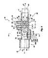
- FIG. 1is an exploded perspective view of a first preferred embodiment of the airway adapter of the present invention in combination with a transducer housing for containing electronics for respiratory and anesthetic agent gas determination;
- FIG. 2is a side elevation view of a first preferred embodiment of the airway adapter of the present invention
- FIG. 2Ais top elevation view of a first preferred embodiment of the airway adapter of the present invention.
- FIG. 3is an end elevation view of the airway adapter of FIG. 2 , looking from plane 3 - 3 ;
- FIG. 4is a side sectional elevation view of the airway adapter of FIG. 2 ;
- FIG. 5is a sectional view of the airway adapter of FIG. 4 , looking upward from plane 5 - 5 extending laterally across the axis of the present invention
- FIG. 6is another sectional elevation view of the airway adapter of FIGS. 2 and 4 , looking from plane 6 - 6 of FIG. 4 , and schematically illustrating a transducer assembled therewith;
- FIG. 7is a cross-sectional representation of an airway adapter that includes a single window through which a luminescence quenching measurement of one or more substances may be obtained and a pair of opposed windows through which an infrared measurement of one or more substances may be obtained;
- FIG. 8is a cross-sectional representation of an airway adapter that includes a single window through which a luminescence quenching measurement of one or more substances may be obtained and another single window and corresponding optics through which an infrared measurement of one or more substances may be obtained;
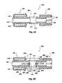
- FIGS. 9 and 11are cross-sectional assembly views of alternative embodiments of airway adapters and transducers according to the present invention, which include pairs of opposed windows through which both luminescence quenching and infrared measurements of one or more substances may be obtained;
- FIGS. 10 and 12are partial views of airway adapter windows of the airway adapter embodiments depicted in FIGS. 9 and 11 , respectively;
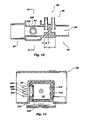
- FIG. 13is a cross-sectional representation of the airway adapter that includes a single window through which both infrared and luminescence quenching measurements may be taken;
- FIG. 14is a cross-section taken along line 14 - 14 of FIG. 13 , also showing a transducer assembled with the airway adapter;
- FIG. 15is a side elevation view of a second preferred embodiment of the airway adapter of the present invention.
- FIG. 16is a side elevation view of a third preferred embodiment of the airway adapter of the present invention.
- FIG. 17is a side sectional elevation of the airway adapter of FIG. 16 ;
- FIG. 18is a bottom view of the airway adapter of FIG. 16 ;
- FIG. 19is a side elevation view of a fourth preferred embodiment of the airway adapter of the present invention.
- FIG. 20is a side sectional elevation of the airway adapter of FIG. 19 ;
- FIG. 21is an end elevation view of the airway adapter along lines 21 - 21 of FIG. 19 ;
- FIG. 22is an end elevation view of the airway adapter along lines 22 - 22 of FIG. 19 ;
- FIG. 23is a sectional view of the airway adapter of FIG. 19 , looking from plane 23 - 23 ;
- FIG. 24is a sectional view of the airway adapter of FIG. 19 , looking from plane 24 - 24 ;
- FIG. 25is a sectional view of the airway adapter of FIG. 19 , looking from plane 25 - 25 ;
- FIG. 26is a sectional view of the airway adapter of FIG. 19 , looking from plane 26 - 26 .
- FIGS. 1-5illustrate an exemplary airway adapter 20 embodying teachings of the present invention.
- Airway adapter 20is preferably a unitary, injection-molded plastic element, so as to afford low manufacturing cost and permit disposal of the sensor after a single use, with a separate transducer housing 22 containing an infrared emitter 252 , an infrared detector 254 , a luminescence excitation radiation source 256 , and a luminescence detector 258 ( FIG. 6 ).
- this configurationis not a requirement.
- airway adapter 20has a generally parallelepipedal center section 32 between and axially aligned with first and second tubular portions 24 and 26 , with a flow passage 34 extending from end-to-end through airway adapter 20 .
- the illustrated airway adapter 20is designed for connection with a breathing circuit that communicates with the airway of a patient.
- Airway adapter 20may be connected between a patient ventilation device and the tubing of a mechanical ventilator.
- first tubular portion 24 of airway adapter 20may be connected to an endotracheal tube inserted in the trachea of a patient, while second tubular portion 26 of airway adapter 20 is attached to the tubing of the mechanical ventilator.
- airway adapter 20may be connected to a breathing mask or other apparatus that are less invasive than endotracheal tubes.
- Airway adapter 20need not be connected to a mechanical ventilator, but may be connected with a source of respiratory gases (e.g., an oxygen source) or communicate directly with the air from the patient's environment.
- a source of respiratory gasese.g., an oxygen source
- first and second tubular portions 24 and 26have bores of varying diameter and substantially circular cross-sections, with a gas concentration monitoring portion 28 disposed therebetween.
- Second tubular portion 26houses a respiratory flow monitoring device 30 .
- Gas concentration monitoring portion 28includes a gas sensing portion 230 , which is configured to employ luminescence quenching techniques to measure the partial pressure or amount of oxygen or other gases that flow through airway adapter 20 .
- gas sensing portion 230also referred to as “gas sensor 230 ,” includes a quantity of luminescable material 232 exposed to a flow passage 34 that extends through airway adapter 20 .
- Gas sensing portion 230also includes a window 234 for facilitating the excitation of luminescable material 232 or some combination of luminescable materials with radiation of one or more excitation wavelengths, as well as the measurement of the intensities of one or more wavelengths of radiation that are emitted from luminescable material 232 , as illustrated in FIGS. 1 , 2 A, and 4 .
- Window 234preferably has a high transmittance for wavelengths of excitation radiation, which excites luminescable material 232 , and for wavelengths of radiation emitted from luminescable material 232 .
- luminescable material 232is preferably carried by a membrane 236 , or matrix, which is disposed on or comprises an integral part of a surface of flow passage 34 .
- a membrane 236 carrying luminescable material 232may be located in another portion of airway adapter 20 that communicates with flow passage 34 .
- Luminescable material 232may be dispersed throughout passages or openings formed in membrane 236 .
- the passages and openings through membrane 236may have diameters or widths of about 0.1 ⁇ m to about 10 ⁇ m, as the diffusion constant for molecular oxygen through membranes of such dimensions is large enough to provide a luminescence quenching response time of sufficiently short duration to facilitate a measurement of luminescence quenching rate on a breath-by-breath basis, or in real time.
- these membrane 236 dimensionsfacilitate the substantially immediate exposure of luminescable material 232 to oxygen and other luminescence quenching substances as these substances flow through or past membrane 236 .
- membrane 236may be removable from the remainder of airway adapter 20 so as to facilitate replacement thereof with a new membrane 236 carrying luminescable material 232 and, thus, to facilitate accurate determinations of the concentration of oxygen or other gases with subsequent use of airway adapter 20 .
- membrane 236may be permanently secured to airway adapter 20 and reused following cleaning and sterilization thereof.
- Porphyrinsare an example of a material that may be used as luminescable material 232 .
- Porphyrinsare stable organic ring structures that often include a metal atom. When the metal atom is platinum or palladium, the phosphorescence decay time ranges from about 10 ⁇ s to about 1,000 ⁇ s. Porphyrins are also sensitive to molecular oxygen. When porphyrins are used as luminescable material 232 , it is preferred that the porphyrins retain substantially all of their photo-excitability with repeated use. Stated another way, it is preferred that the porphyrins be “photostable.” Fluorescent porphyrins, such as meso-tetraphenyl porphines, are particularly photostable.
- porphyrinsthat may be used as luminescable material 232 to facilitate oxygen detection include, without limitation, platinum meso-tetra(pentafluoro)phenyl porphine, platinum meso-tetraphenyl porphine, palladium meso-tetra(pentafluoro)phenyl porphine, and palladium meso-tetraphenyl porphine.
- platinum meso-tetra(pentafluoro)phenyl porphineplatinum meso-tetraphenyl porphine, platinum meso-tetraphenyl porphine, palladium meso-tetra(pentafluoro)phenyl porphine, and palladium meso-tetraphenyl porphine.
- other types of luminescable materialsthat are known to be quenched upon being exposed to oxygen, carbon dioxide, or another analyzed substance (e.g., gas, liquid, or vapor) may also be used
- Membrane 236is preferably formed from a material that is compatible with luminescable material 232 . Moreover, it is preferred that the material of membrane 236 be compatible with respiratory gases, as well as non-toxic to the patient and, preferably, to the environment.
- membrane 236Materials that may be used to form membrane 236 include, but are not limited to, porous polyvinylchloride (PVC), polypropylene, polycarbonate, polyester, polystyrene, polymethacrylate polymers, and acrylic copolymers.
- PVCporous polyvinylchloride
- polypropylenepolypropylene
- polycarbonatepolycarbonate
- polyesterpolystyrene
- polymethacrylate polymerspolymethacrylate polymers
- acrylic copolymersacrylic copolymers.
- microporous polycarbonate filtration membranesavailable from Pall Gelman Sciences of Ann Arbor, Mich., and from Whatman, Inc. of Clifton, N.J., (track-etched microporous polycarbonate filtration membranes with a thickness of about 10 ⁇ m and a pore size of about 0.4 ⁇ m) are useful as membrane 236 .
- membrane 236be permeable to respiratory gases, including oxygen. As respiratory gases flow past, into, or through membrane 236 , the respiratory gases, including oxygen, contact luminescable material 232 carried thereby. The luminescence of, or intensity of radiation emitted from, luminescable material 232 is then quenched to a degree that is based on the amount of oxygen or other luminescence quenching gases in the respiratory gases.
- the permeability of membrane 236 to respiratory gasesalso has an affect on the number of luminescable material 232 particles that is exposed to the respiratory gases and may, therefore, affect the amount of luminescence quenching that occurs as luminescable material 232 is exposed to oxygen and other luminescence quenching gases present in the respiratory gases that flow through membrane 236 .
- Luminescable material 232may be applied to membrane 236 by known processes.
- a solventmay be used to introduce luminescable material 232 onto a surface of membrane 236 , as well as into openings thereof.
- the solventdoes not substantially dissolve the material of membrane 236 .
- the solventmay, however, interact with the material of membrane 236 in a manner that causes membrane 236 and the openings thereof to swell, so as to facilitate the introduction of luminescable material 232 into the openings.
- Exemplary solvents that may be used to apply luminescable material 232 to membrane 236include, without limitation, hexane, petroleum ethane, toluene, tetrahydrofuran, methylene chloride, trichloroethylene, xylene, dioxane, isopropyl alcohol, and butanol, as well as mixtures of any of the foregoing.
- the use of a particular solventdepends on its compatibility with both luminescable material 232 and with the material of membrane 236 .
- the solventmay be evaporated or otherwise removed from membrane 236 in a manner that leaves luminescable material 232 on the surface and within the openings of membrane 236 .
- luminescable material 232may be sandwiched between two membranes 236 .
- a solvent that will not significantly degrade luminescable material 232dissolves the material of membranes 236 enough to bond membranes 236 to one another to form a single composite membrane 240 , but without substantially altering the structures of membranes 236 .
- Luminescable material 232remains between membranes 236 and may at least partially permeate membranes 236 . As membranes 236 trap luminescable material 232 therebetween, increased concentrations of luminescable material 232 may be incorporated into composite membrane 240 relative to the concentration of luminescable material 232 contained by a single membrane 236 .
- sensor 230may include an overcoat layer 242 over membrane 236 .
- Overcoat layer 242may be formed from a polymer, such as the same type of polymer from which membrane 236 is formed, or from a different type of polymer than that from which membrane 236 is formed. Overcoat layer 242 does not substantially prevent gases in the respiration of an individual from contacting luminescable material 232 .
- Overcoat layer 242may also refine or tailor various properties of membrane 236 , including, without limitation, the light absorption properties of membrane 236 , the light transmission properties of membrane 236 , and the permeability of membrane 236 to various gases. As an example of the use of an overcoat layer 242 to tailor the properties of membrane 236 , permeability of membrane 236 to oxygen or other respiratory gases may be reduced by applying to membrane 236 an overcoat layer 242 formed from a less permeable material.
- overcoat layer 242may be applied to membrane 236 .
- a dissolved polymermay be applied to membrane 236 to form overcoat layer 242 .
- a preformed overcoat layer 242may be adhered to membrane 236 by known means, so long as the overcoated membrane 236 retains the desired properties.
- membrane 236 thereofis preferably disposed over a thermal source of a known type, such as thermal capacitor 244 .
- Thermal capacitor 244communicates with a heater component 246 ( FIG. 6 ), which heats thermal capacitor 244 to a desired, substantially constant temperature. Because thermal capacitor 244 contacts membrane 236 , thermal capacitor 244 , in turn heats membrane 236 to a substantially constant temperature. Accordingly, thermal capacitor 244 substantially prevents temperature changes of member 236 or of luminescable material 232 thereon from affecting the luminescence quenching caused by oxygen or other substances flowing past luminescable material 232 .
- thermal capacitor 244 and heater component 246may communicate with each other includes providing a floating, thermally conductive heater component 246 on transducer housing 22 ( FIGS. 6 ). Upon coupling transducer housing 22 with airway adapter 20 , heater component 246 and thermal capacitor 244 contact one another in such a manner as to provide an efficient transfer of heat from heater component 246 to thermal capacitor 244 .
- Transducer housing 22at least partially contains a radiation source 256 , which emits electromagnetic excitation radiation of one or more wavelengths that will excite luminescable material 232 into luminescence.
- radiation source 256may comprise a light-emitting diode (LED), which produces excitation radiation in the form of visible light.
- Radiation source 256preferably emits excitation radiation of wavelengths that will excite luminescable material 232 to emit a desired intensity of radiation. Excitation radiation emitted from radiation source 256 passes through and is focused by a lens 257 , which directs the focused excitation radiation toward luminescable material 232 .
- Transducer housing 22also contains at least a portion of a detector 258 positioned to receive radiation emitted from luminescable material 232 and configured to measure an intensity of such emitted radiation. Accordingly, detector 258 is positioned toward window 234 and toward luminescable material 232 . Preferably, a filter 259 is disposed between luminescable material 232 and detector 258 so as to prevent wavelengths of electromagnetic radiation other than those emitted from luminescable material 232 from interfering with the luminescence and luminescence-quenching measurements obtained with detector 258 .
- Other features and advantages of a luminescence quenching type sensorthat may also be employed in the present invention are disclosed in U.S. Pat. Nos. 6,815,211 and 6,325,978, filed on Aug. 4, 1998, both of which have been assigned to the same assignee as the present invention, the disclosures of which are hereby incorporated in their entireties by this reference.
- Gas concentration monitoring portion 28 of airway adapter 20provides a seat for transducer housing 22 .
- An integral, U-shaped casing element 36positively locates transducer housing 22 across airway adapter 20 and in the transverse direction indicated by arrow 38 in FIG. 1 .
- Arrow 38also shows the direction in which transducer housing 22 is displaced to detachably assemble it to airway adapter 20 .
- transducer housing 22snaps into place on airway adapter 20 , as disclosed in the '858 and '859 Patents; no tools are needed to assemble adapter 20 and transducer housing 22 or to remove transducer housing 22 from airway adapter 20 .
- Center section 32may also include an infrared sensor portion 33 with first and second axially aligned windows 40 and 42 , respectively (only window 42 is shown in FIG. 4 ).
- Windows 40 and 42preferably have a high transmittance for radiation in at least the intermediate infrared portion of the electromagnetic spectrum.
- the substantial axial alignment of first window 40 and second window 42allows an infrared radiation beam to travel from infrared radiation emitter 252 in one leg 22 a of transducer housing 22 , transversely through airway adapter 20 and the one or more gases flowing through flow passage 34 of airway adapter 20 , to infrared detector 254 in the opposing, substantially parallel leg 22 b of transducer housing 22 .
- Cuvette windows 40 and 42 for infrared absorption measurementshave typically been fabricated from sapphire because of sapphire's favorable optical properties, stability, and resistance to breakage, scratching, and other forms of damage.
- the cost of the cuvettecan be reduced to the point of making it practical to dispose of the cuvette after a single use by fabricating the cuvette windows from an appropriate polymer. It is essential to the accuracy of infrared absorption portion of the gas concentration monitor that the polymer transmit a usable part of the infrared radiation impinging upon it.
- the window materialmust have the appropriate optical properties for measuring the desired substances.
- An exemplary window material exhibiting such properties with respect to measuring an amount of carbon dioxide present in the respiration of a patientis biaxially oriented polypropylene. Other materials may also be used, depending upon the transmissivities thereof for certain wavelengths of radiation that are to be used to detect the presence or amounts of particular substances in the respiration of a patient.
- a transducer housing 22which carries electronic components that are designed to facilitate the output of one or more reference signals and one or more signals related to the concentrations of corresponding respiratory or anesthetic gases flowing through airway adapter 20 .
- An infrared radiation emitter 252 of transducer housing 22is configured to direct infrared radiation of one or more wavelengths into center section 32 of airway adapter 20 through window 40 , through a sample of respiratory gases within center section 32 , and out of center section 32 through window 42 .
- Infrared detector 254which is positioned adjacent window 42 when transducer housing 22 is assembled with airway adapter 20 , is positioned to receive infrared radiation signals that exit center section 32 of airway adapter 20 through window 42 .
- infrared detector 254which preferably monitors, in real time, the amounts of CO 2 , N 2 O, or anesthetic agents in the respiration of an individual is thoroughly discussed in U.S. Pat. No. 5,616,923 (hereinafter “the '923 Patent”), incorporated herein in its entirety by this reference. It is understood that infrared CO 2 monitor devices such as those disclosed in the '858, '859, and '436 Patents, as well as other CO 2 detection devices, could be used in transducer housing 22 . In addition to one or more infrared sensors, infrared detector 254 may include any combination of other components, including a reference sensor, optics (e.g., lenses, filters, mirrors, beam splitters, etc.), coolers, and the like.
- opticse.g., lenses, filters, mirrors, beam splitters, etc.
- the infrared signals detected by infrared detector 254can be ratioed to provide a signal accurately and dynamically representing the amount of CO 2 , N 2 O, or an anesthetic agent flowing through airway adapter 20 .
- FIG. 7illustrates another embodiment of airway adapter 20 ′′ and of a complementary transducer housing 22 ′′ assembled therewith.
- Airway adapter 20 ′′includes a window 234 formed through a top portion thereof.
- Window 234is transparent to (i.e., has a high transmissivity for) wavelengths of radiation that are used to excite luminescable material 232 on a membrane 236 positioned within flow passage 34 and adjacent to window 234 .
- window 234is transparent to one or more wavelengths of radiation that are emitted from luminescable material 232 and quenched by an analyzed substance to a degree that relates to an amount of the analyzed substance in respiration of an individual or in another gas mixture.
- airway adapter 20 ′′includes windows 40 , 42 positioned on opposite sides of flow passage 34 .
- Windows 40 and 42facilitate the direction of radiation of one or more specified infrared wavelengths across flow passage 34 to facilitate the measurement of amounts of one or more substances, such as carbon dioxide or nitrous oxide or other anesthetic agents, that are present in the respiration of an individual as the individual's respiration passes through a location of flow passage 34 between which windows 40 and 42 are positioned.
- windows 40 and 42are each preferably formed from a material that is substantially transparent to (i.e., has a high transmissivity for) infrared wavelengths that are desired for use in measuring amounts of one or more substances in respiration of the individual.
- Transducer housing 22 ′′contains at least a portion of a radiation source 256 positioned to direct one or more wavelengths of radiation that are capable of exciting luminescable material 232 into luminescence through window 234 , toward luminescable material 232 .
- Radiation source 256may include optics (e.g., filters, lenses, beam splitters, etc.) that direct radiation toward the appropriate location and that filter out one or more undesirable wavelengths of the radiation emitted from radiation source 256 .
- transducer housing 22 ′′carries a luminescence detector 258 , as well as any optics (e.g., filters, lenses, beam splitters, etc.) associated therewith, which are respectively positioned to receive and detect at least one wavelength or radiation that is emitted by luminescable material 232 and that is quenched by exposure to a substance of interest to a degree that indicates an amount of the substance to which luminescable material 232 is exposed.
- any opticse.g., filters, lenses, beam splitters, etc.
- An infrared emitter 252 and an infrared detection component 254are positioned in opposite legs 22 a ′′, 22 b ′′, respectively, of transducer housing 22 ′′.
- Infrared emitter 252is oriented within transducer housing 22 ′′ so as to direct one or more infrared wavelengths of radiation through window 40 , across flow passage 34 , and through window 42 as transducer housing 22 ′′ is assembled with airway adapter 20 ′′.
- Infrared detection component 254which is positioned adjacent window 42 when transducer housing 22 ′′ is assembled with airway adapter 20 ′′, is oriented so as to receive and detect the one or more infrared wavelengths of radiation emitted by radiation source 252 that exit airway adapter 20 ′′ through window 42 .
- an airway adapter 20 ′′′incorporating teachings of the present invention includes a single window 40 through which an infrared emitter 252 and infrared detector 254 may be used to measure an amount of a substance, such as carbon dioxide, nitrous oxide or another anesthetic agent, in the respiration of an individual.
- a substancesuch as carbon dioxide, nitrous oxide or another anesthetic agent
- Window 40 of airway adapter 20 ′′′is positioned on one side of flow passage 34 to facilitate the introduction of one or more infrared wavelengths of radiation into flow passage 34 , while optics 41 , which reflect or otherwise redirect infrared wavelengths of radiation back across flow passage 34 and through window 40 , are positioned at least partially across flow passage 34 from window 40 .
- Window 40may be formed from a material that is substantially transparent to (i.e., has a high transmissivity for) infrared wavelengths that are desired for use in measuring amounts of one or more substances in respiration of the individual.
- Optics 41may include one or more mirrors or reflective coatings, as well as other optical components of known types (e.g., lenses, filters, etc.) to direct a beam of radiation that originated from a infrared emitter 252 within transducer housing 22 ′′′ and was introduced into flow passage 34 of airway adapter 20 ′′′ back across flow passage 34 , through window 40 , and to an infrared detection component 254 carried by transducer housing 22 ′′′, positioned adjacent infrared emitter 252 .
- known typese.g., lenses, filters, etc.
- airway adapter 20 ′′′is configured to seat a transducer housing 22 ′′′, which carries infrared emitter 252 and infrared detector 254 .
- infrared emitter 252is oriented such that infrared emitter 252 is positioned to emit infrared wavelengths of radiation into window 40 , at least partially across flow passage 34 , toward optics 41 .
- infrared detector 254is oriented so as to receive infrared wavelengths of radiation that have been redirected by optics 41 back out of window 40 .
- each infrared wavelengthmay be attenuated, or decreased in intensity, to a degree that correlates to an amount of a corresponding substance present in the individual's respiration.
- an airway adapter 120 of the present inventionmay include a single pair of windows 140 and 142 through which both infrared and luminescence quenching measurements may be obtained.
- Window 140is substantially transparent to (i.e., has a high transmissivity for) at least one wavelength of radiation that excites luminescable material 232 into luminescence.
- window 140is substantially transparent to one or more of infrared wavelengths of radiation that are useful for measuring amounts of one or more substances present in respiration or other gas mixtures passing through a location of flow passage 34 positioned between windows 140 and 142 .
- Window 142is substantially transparent to the one or more infrared wavelengths of radiation to which window 140 is substantially transparent. Window 142 is also substantially transparent to at least one wavelength of radiation that is emitted by luminescable material 232 , the intensity of which decreases at a rate that is indicative of an amount of a measured substance in respiration within flow passage 34 .
- a membrane 236 carrying luminescable material 232is positioned adjacent to a portion of window 142 .
- membrane 236is semicircular in shape.
- FIGS. 11 and 12depict a membrane 236 having an annular shape, and positioned adjacent an outer periphery of window 142 .
- Membranes 236 of other shapes and covering different portions of window 142are also within the scope of the present invention.
- a transducer housing 122 configured complementarily to airway adapter 120includes two legs 122 a and 122 b , one of which (first leg 122 a ) is configured to be positioned adjacent to window 140 and the other of which (second leg 122 b ) is configured to be positioned adjacent to window 142 .
- First leg 122 a of transducer housing 122carries infrared emitter 252 and radiation source 256 , which emits at least one wavelength of radiation that will excite luminescable material 232 .
- Both infrared emitter 252 and radiation source 256are positioned to emit their respective wavelengths of radiation into window 140 and through flow passage 34 .
- infrared emitter 252is also oriented so as to direct radiation emitted therefrom through an unobstructed (by membrane 236 ) portion of window 142
- radiation source 256is oriented to direct radiation emitted therefrom toward membrane 236 so as to excite luminescable material 232 carried thereby into luminescence.
- membrane 236may substantially cover window 142 if membrane 236 and luminescable material 232 thereon are substantially transparent to one or more wavelengths of infrared radiation that are used to detect the partial pressure or amount of carbon dioxide or one or more other substances present in respiratory or other gases that are flowing through airway adapter 120 .
- Second leg 122 b of transducer housing 122carries an infrared detection component 254 and luminescence detector 258 .
- Infrared detection component 254is positioned to receive and detect one or more infrared wavelengths of radiation exiting airway adapter 120 through window 142 .
- Luminescence detector 258is oriented to receive and detect one or more wavelengths of radiation that are emitted from luminescable material 232 and that are quenched, or reduced in intensity, to a degree representative of an amount of a monitored substance in respiration to which luminescable material 232 is exposed.
- radiation source 256may be located within second leg 122 b of transducer housing 122 and positioned to direct radiation toward a portion of window 142 adjacent to which membrane 236 with luminescable material 232 thereon is positioned.
- one or both of luminescence sensor 258 and radiation source 256could be carried by first leg 122 b of transducer housing 122 .
- FIGS. 13 and 14depict another exemplary embodiment of airway adapter 20 ′ incorporating teachings of the present invention, which includes a single window 40 ′ through which measurements of the amounts of oxygen, carbon dioxide, and anesthetic agents in the respiration of an individual may be obtained.
- membrane 236 ′which carries luminescable material 232 , is positioned within flow passage 34 ′ on a portion of window 40 ′. While membrane 236 ′ is depicted as being annular in shape and covering a periphery of window 40 ′, airway adapters with other shapes of membranes are also within the scope of the present invention.
- the membrane that carries luminescable material 232need not be positioned on window 40 ′, but may be positioned elsewhere within flow passage 34 ′ or in a location that is in flow communication with flow passage 34 ′.
- Airway adapter 20 ′also includes one or more mirrors 41 a ′, 41 b ′ ( FIG. 14 ) that are positioned so as to facilitate measurement of the amounts of one or more of oxygen, carbon dioxide, and anesthetic agents in the respiration of an individual through window 40 ′. As depicted, airway adapter 20 ′ includes mirrors 41 a ′, 41 b ′, which facilitate collection of measurements that are indicative of an amount of carbon dioxide and/or an anesthetic agent in an individual's respiration.
- each mirror 41 ′may shaped or positioned within flow passage 34 so as to reflect radiation that has been introduced into flow passage 34 through window 40 ′ and that has traversed at least a portion of the distance across flow passage 34 back through window 40 ′.
- mirror 41 ′may actually comprise a group of mirrors or other optical elements (e.g., filters, lenses, etc.) or known types to facilitate the direction of radiation of particular wavelengths to the appropriate locations.
- a transducer housing 22 ′that is configured to be assembled with airway adapter 20 ′ includes a radiation source 256 ′ and a corresponding luminescence detector 258 ′.
- Radiation source 256 ′emits at least one wavelength of electromagnetic radiation that will excite luminescable material 232 .
- Radiation source 256 ′is positioned to introduce one or more wavelengths of excitation radiation through window 40 ′ and onto luminescable material 232 . At least a portion of the radiation that is emitted from luminescable material 232 is then received by luminescence detector 258 ′.
- Luminescence detector 258 ′detects at least one wavelength of radiation emitted from luminescable material 232 that indicates an amount of oxygen present in respiration or another gas mixture flowing through flow passage 34 .
- Transducer housing 22 ′may also carry an infrared radiation emitter 252 and an infrared detector 254 .
- Infrared emitter 252emits one or more wavelengths of radiation that are useful for detecting an amount of carbon dioxide, an anesthetic agent, or another gas or vaporized material that are present in respiration or another mixture of gases located within flow passage 34 ′.
- infrared emitter 252is positioned to direct the one or more wavelengths of radiation into window 40 ′, at least partially across flow passage 34 ′, and toward mirror 41 a ′, 41 b ′.
- Mirror 41 a ′, 41 b ′then reflects the one or more wavelengths of radiation back toward a location of window 40 ′ where the radiation will be received or sensed by infrared detector 254 .
- one or more lensesmay be associated with radiation source 256 ′ and/or luminescence detector 258 ′ to focus radiation being emitted by radiation source 256 ′ or received by luminescence detector 258 ′.
- One or more filtersmay similarly be associated with radiation source 256 ′ to limit the wavelengths of radiation to which luminescable material 232 is exposed.
- one or more filtersmay be associated with luminescence detector 258 ′ to restrict the wavelengths of radiation that may be received thereby.
- airway adapter 20 , 20 ′ and transducer housing 22 , 22 ′may be molded from a polycarbonate or a comparable rigid, dimensionally stable polymer. Nonetheless, several factors, including, without limitation, the type of luminescable material 232 being used, as well as wavelengths of radiation that excite luminescable material 232 , that are emitted by luminescable material 232 , and that are used to detect other substances, such as carbon dioxide or nitrous oxide or other anesthetic agents, may also be taken into consideration when selecting the material or materials that are to be used to form airway adapter 20 , 20 ′. Such factors may also be considered when selecting one or more materials from which transducer housing 22 , 22 ′ will be formed.
- an airway adapter 20 , 20 ′ incorporating teachings of the present inventionincludes luminescable material 232
- the material or materials from which airway adapter 20 , 20 ′ and transducer housing 22 , 22 ′ are formedpreferably prevent luminescable material 232 from being exposed to wavelengths of ambient light which may excite luminescable material 232 (i.e., the material or materials are opaque to such wavelengths of radiation).
- airway adapter 20 , 20 ′ and transducer housing 22 , 22 ′preferably prevent luminescence detector 258 from being exposed to the same wavelengths of ambient radiation that luminescable material 232 emit upon being excited and that are quenched, or reduced in intensity, to a degree that is representative of an amount of oxygen or another analyzed gas or vaporized material to which luminescable material 232 is exposed.
- One or both of airway adapter 20 , 20 ′ and transducer housing 22 , 22 ′may also be equipped with light sealing elements or optical filters that further prevent luminescable material 232 and luminescence detector 258 , 258 ′ from being exposed to undesirable wavelengths of ambient radiation.
- the material or materials from which airway adapter 20 , 20 ′ and transducer housing 22 , 22 ′ are formeddo not emit or fluoresce wavelengths of radiation that would either excite luminescable material 232 or be emitted therefrom upon exposure of airway adapter 20 , 22 ′ or transducer housing 22 , 22 ′ to either ambient radiation or to wavelengths of radiation that are emitted by infrared emitter 252 , radiation source 256 , 256 ′, or excited luminescable material 232 .
- Portions of airway adapter 20 , 20 ′ or transducer housing 22 , 22 ′, such as window 40 , through which one or more wavelengths of radiation are to be transmittedare preferably formed from materials that do not absorb a substantial amount of the one or more wavelengths of radiation that are to be transmitted therethrough. Stated another way, these portions of airway adapter 20 , 20 ′ or transducer housing 22 , 22 ′ should be relatively transparent to the wavelengths of radiation that are indicative of an amount of one or more particular substances in the respiration of a patient.
- polypropylenein airway adapter 20 , 20 ′ or in transducer housing 22 , 22 ′, while polypropylene has a high transmissivity for wavelengths that are used to detect carbon dioxide levels, polypropylene may not have good transmissivity for wavelengths of radiation that may be used to detect levels of other substances.
- airway adapter 20may include a respiratory flow monitoring device 30 within first tubular portion 24 (most clearly seen in FIGS. 4 and 5 ).
- Respiratory flow monitoring device 30 of airway adapter 20may comprise any known, suitable type of respiratory flow monitor.
- An exemplary respiratory flow monitoring device 30includes a diametrically-oriented longitudinally-extending strut 44 of axial length L and height H 1 within a tubular housing 46 of airway adapter 20 .
- Strut 44has first and second end faces 50 and 52 , and first and second side faces 54 and 56 .
- end faces 50 and 52may be substantially perpendicular to axis A, as shown in FIG. 5 , and chamfered and rounded, as shown, so long as the end face configuration is symmetrical when viewed from above.
- the major characteristic of end faces 50 and 52aside from symmetry, is that they do not incline toward notches 58 and 60 or otherwise collect or direct flow through flow monitoring device 30 toward notches 58 and 60 and pressure ports 62 and 66 .
- End faces 50 and 52are preferably aerodynamically designed so as to minimize resistance to the gas flow.
- side faces 54 and 56 of strut 44are flat, again the major requirement being one of symmetry between the sides of strut 44 , as with end faces 50 and 52 .
- Strut 44also provides a position for pressure port apertures 62 and 66 and conditions the velocity profile of the flowing gas. Strut 44 is offset from an inner wall 48 of tubular housing 46 and is secured, at both ends, to inner wall 48 .
- the cross-sectional area of the 44 transverse to a bore axis Ashould be minimized. The minimization of this dimension is, however, constrained by the diameters of pressure port apertures 62 and 66 .
- the cross sectional area of strut 44may be about five percent (5%) of the cross-sectional bore area of tubular housing 46 at the location of strut 44 .
- first tubular portion 24 and second tubular portion 26are different between first tubular portion 24 and second tubular portion 26 .
- This configurationaccommodates a male connecting tube element shown in broken lines and designated as M on the left-hand side or first tubular portion 24 of airway adapter 20 , and a female connecting tube element F on the right-hand side of second tubular portion 26 of airway adapter 20 .
- the internal bores of first and second tubular portions 24 and 26may be tapered to facilitate the release of plastic injection molding mold parts from a formed airway adapter 20 .
- Strut 44further includes notch structures comprising substantially symmetrical first and second notches 58 and 60 , both of which are located substantially on axis A of tubular housing 46 , notches 58 and 60 extending axially inwardly from first and second end faces 50 and 52 , respectively, and laterally through first and second side faces 54 and 56 , respectively.
- a first pressure port 62 of a first lumen 64opens into first notch 58
- a second pressure port 66 of a second lumen 68opens into second notch 60
- first and second lumens 64 and 68comprise passages internal to strut 44 , which extend into and through first and second male stems 70 and 72 , respectively, on exterior surface 74 of tubular housing 46 .
- Airway adapter 20is preferably oriented with first and second male stems 70 and 72 directed upward, such that water condensation and mucus do not clog or otherwise impair pressure ports 62 and 66 .
- Both pressure ports 62 and 66face substantially perpendicular to axis A of tubular housing 46 , notches 58 and 60 extend axially inwardly to a depth D, at least past pressure ports 62 and 66 , and may so extend a distance equal to the height H 2 of notches 58 and 60 , which, in turn, should be less than or equal to four-tenths ( 4/10) of the height H 1 of the strut 44 .
- Back walls 78 and 80 of notches 58 and 60may be arcuate or radiused, as shown in FIG. 5 , or otherwise symmetrically shaped, as with the end faces 50 and 52 .
- Back walls 78 and 80may also have substantially planar surfaces.
- Floors 82 and 84 and ceilings 86 and 88 of notches 58 and 60are preferably substantially planar, or flat, as shown in FIG. 4 , or may be otherwise symmetrically shaped.
- the transition edges or lines between end faces 50 and 52 and notches 58 and 60are preferably radiused, although they may alternatively be chamfered or beveled.
- Back walls 78 and 80 of notches 58 and 60 , respectively, together with restrictions (ridges or lands) 90comprise an obstruction 76 and/or perturbation to the gas flow through flow monitoring device 30 , which generates the differential pressure signal measured at first and second pressure ports 62 and 66 .
- the measured differential pressure signalis from either pressure loss or from vena contracta, the contraction of the velocity profile of flowing gases, which is caused by obstruction 76 .
- the differential pressure generated from the vena contractacan be modeled by standard fluid mechanics equations such as Euler's or Bernoulli's equation.
- the differential pressure signal generated from vena contractais considered “lossless”, meaning that the pressure is restored as the velocity profile is returned to the incident velocity profile.
- Respiratory flowis proportional to the square root of the differential pressure, as measured at pressure ports 62 and 66 .
- Flow obstruction 76may be varied in a number of ways to yield a different magnitude of measured differential pressure for a given flow rate.
- the cross-sectional area of restrictions (ridges or lands) 90may be increased or decreased in the plane perpendicular to axis A.
- the distance from the center of first pressure port 62 to back wall 78 of notch 58 and, likewise, the distance from the center of the second pressure port 66 to back wall 84 of notch 60may be varied to change the flow response characteristics.
- the magnitude of the differential pressure signal for a given flow ratecan be further increased by reducing the cross-sectional bore area by necking down the inner wall of tubular housing 46 .
- the length and width of strut 44may be altered, as desired, to change flow characteristics. These flow characteristics include flow conditioning, signal strength, and signal stability. Ideally, the incident velocity profile to the obstruction should be the same regardless of the velocity profile incident to airway adapter 20 . Signal stability may be compromised when unstable, multi-dimensional vortex formations are generated by flow obstruction 76 . Strut 44 with notch means provides flow conditioning that yields some immunity to inlet velocity profile and yields a stable differential pressure signal in response to the gas flow.
- Flow monitoring device 30may be selectively modified to adapt to the conditions under which flow monitoring device 30 is to operate.
- the modification of the cross-sectional flow area in the vicinity of strut 44may be employed to adjust the dynamic range of the respiratory flow monitoring device 30 , as may modifications to the configurations of end faces 50 and 52 , back walls 78 and 80 of notches 58 and 60 , and to the lines of transition between notches 58 and 60 and end faces 50 and 52 and side faces 54 and 56 .
- strut 44laterally extending transversely oriented center (strut 44 ) restrictions (ridges or lands) 90 and a gradual inner wall transition in the strut area axial length to add symmetry to the flow pattern, normalize the flow, immunity to moisture, and provide better repeatability of readings.
- the notch height H 2 or the length of strut 44may be increased or decreased to accommodate a wider range of inlet conditions, such as might result from employment of flow monitoring device 30 with a variety of endotracheal tubes.
- FIG. 15illustrates a second embodiment of airway adapter 20 ′ incorporating teachings of the present invention.
- Airway adapter 20 ′includes a plurality of ribs 21 around the outside diameter of a first portion 24 ′ thereof. Ribs 92 preferably define a 22 mm diameter and reduce the weight of airway adapter 20 ′ while providing uniform wall dimensions to facilitate injection molding of airway adapter 20 ′.
- FIGS. 16-18illustrate third embodiment of an airway adapter 100 with reduced dead space relative to the embodiments disclosed previously herein.
- Airway adapter 100is particularly suitable for use in situations where the respiratory tidal volume is extremely small, such as with newborn infants, although airway adapter 100 has equal utility in adult and pediatric respiratory monitoring.
- airway adapter 100is designed for connection between a patient ventilation device, such as an endotracheal tube inserted into a patient's trachea, attached to a first tubular portion 104 of airway adapter 100 , and the tubing of a mechanical ventilator, attached at second tubular portion 106 of airway adapter 100 .
- First and second tubular portions 104 and 106have bores of varying diameter and of substantially circular cross-section.
- a gas concentration monitoring portion 108 of airway adapter 100is disposed between first and second tubular portions 104 and 106 .
- Gas concentration monitoring portion 108 of airway adapter 100provides a seat for a transducer housing (not shown), similar to transducer housing 22 shown in FIG. 1 .
- An integral, U-shaped casing element 112positively locates the transducer housing into position on airway adapter 100 .
- the transducer housingsnaps into place on airway adapter 100 without the need for tools to assemble or disassemble the transducer and airway adapter 100 .
- airway adapter 100includes an annular recess 141 formed in first portion 104 .
- Annular recess 141accommodates a male connecting tube element, shown in broken lines and designated as M 1 , on the left-hand side of first portion 104 of airway adapter 100 .
- Second tubular portion 106similarly includes a receptacle 143 configured to accommodate a second male connecting tube element M 2 , as shown in broken lines, which snaps into receptacle 143 by engaging a stepped slot 145 thereof.
- Elements M 1 and M 2each include a bore of like diameter to the corresponding bores 130 and 124 of airway adapter 100 .
- Elements M 1 and M 2facilitate communication between airway adapter 100 and the airway of an individual and, if necessary, a respirator or other ventilation device.
- Gas concentration monitoring portion 108includes a luminescent sensing window 234 formed through U-shaped casing element 112 .
- Window 234facilitates the emission of excitation radiation from a source of excitation radiation within a transducer housing assembled with airway adapter 100 , into airway adapter 100 , and toward luminescable material (e.g., luminescable material 232 shown in FIG. 4 ) within airway adapter 100 .
- window 234facilitates the detection of luminescence emitted from the luminescable material of airway adapter 100 by a detector within the transducer housing, as discussed previously herein with reference to FIG. 6 .
- Gas concentration monitoring portion 108also includes a first axially aligned window 116 and a second axially aligned window 118 (shown in FIG. 17 only) to allow an infrared radiation beam to travel from an infrared radiation emitter (see FIG. 1 ) in the transducer housing transversely through a sampling chamber 114 in airway adapter 100 for monitoring gases, such as CO 2 , N 2 O, and anesthetic agents, as discussed previously herein.
- gasessuch as CO 2 , N 2 O, and anesthetic agents
- Airway adapter 100includes a respiratory flow monitoring device 110 , which partially resides in first tubular portion 104 , partially resides in second tubular portion 106 , and partially resides in gas concentration monitoring portion 108 .
- Respiratory flow monitoring device 110which is most clearly depicted in FIG. 17 , also includes a first pressure port 125 of a first lumen 122 which opens into a first tubular chamber 124 of the tubular portion 104 , and a second pressure port 126 of a lumen 128 which opens into second tubular chamber 130 .
- Lumens 122 and 128extend to respective first and second recesses 132 , 134 , which are configured to minimize dead space and accommodate connecting tubes, shown in broken lines and designated as T 1 and T 2 .
- Tubes T 1 and T 2are connected to a flow monitor (not shown), which determines flow rate through a pressure differential detected between pressure ports 125 and 126 . This pressure differential is produced through the use of necked-down ports 136 and 138 at the longitudinal ends of gas sampling chamber 114 .
- the effects of water condensationare of particular concern in this embodiment due to its small volume and intended neonatal use, therefore, the airway adapter 100 should be positioned such that recesses 132 and 134 are directed upward to prevent clogging.
- this embodimenthas many advantages, such as minimization of deadspace and moldability in one piece.
- FIGS. 19-26illustrate a fourth preferred embodiment of an airway adapter 200 , which is similar to the airway adapter 100 of FIGS. 16-18 . Therefore, components common to airway adapters 100 and 200 , depicted in FIGS. 16-18 and FIGS. 19-26 , respectively, retain the same numeric designation. Airway adapter 200 is particularly suitable for use in situations where the respiratory tidal volumes is extremely small, such as with newborn infants, although it has equal utility in pediatric and adult respiratory monitoring.
- Airway adapter 200is designed for connection between a patient ventilation device, such as an endotracheal tube inserted in a patient's trachea, attached to the first tubular portion 104 , and the tubing of a mechanical ventilator, attached at second tubular portion 106 .
- First and second tubular portions 104 and 106have bores of varying diameter and of substantially circular cross-section, with gas concentration monitoring portion 108 positioned therebetween.
- Gas concentration monitoring portion 108 of airway adapter 200provides a seat for a transducer housing (not shown), similar to transducer housing 22 shown in FIG. 1 .
- An integral, U-shaped casing element 112positively locates the transducer housing into position on airway adapter 200 .
- the transducer housingsnaps into place on airway adapter 200 without the need for tools to assemble or disassemble airway adapter 200 and the transducer housing.
- annular recess 142is formed in first portion 104 to accommodate a male connecting tube element, shown in broken lines and designated as M 1 , on the left-hand side of first portion 104 of airway adapter 200 .
- Second tubular portion 106includes a receptacle 143 that accommodates a second male connecting tube element M 2 , as shown in broken lines, which snaps into receptacle 143 by engaging a stepped slot 145 thereof.
- Elements M 1 and M 2include bores of like diameter to bores 124 , 130 .
- Elements M 1 and M 2facilitate communication between airway adapter 200 and the airway of an individual and, if necessary, a respirator or other ventilation device.
- Gas concentration monitoring portion 108includes a luminescent sensing window 234 formed through U-shaped casing element 112 .
- Window 234facilitates the emission of excitation radiation from a source of excitation radiation within a transducer housing assembled with airway adapter 200 , into airway adapter 200 toward luminescable material (e.g., luminescable material 232 shown in FIG. 4 ) within airway adapter 200 .
- window 234facilitates the detection of luminescence emitted from the luminescable material of airway adapter 200 by luminescence detector 258 within transducer housing 22 , as discussed previously herein with reference to FIG. 6 .
- Gas concentration monitoring portion 108also includes a first axially aligned window 116 and a second axially aligned window 116 and a second axially aligned window 118 to facilitate the transmittance of an infrared radiation beam from an infrared radiation emitter in the transducer housing, transversely through sampling chamber 114 in airway adapter 200 so that amounts of gases, such as CO 2 , N 2 O, and anesthetic agents in the respiration of an individual may be monitored as discussed previously herein.
- gasessuch as CO 2 , N 2 O, and anesthetic agents in the respiration of an individual may be monitored as discussed previously herein.
- Airway adapter 200includes a respiratory flow monitoring device 110 , which partially resides in first tubular portion 104 , partially resides in second tubular portion 106 , and partially resides in gas concentration monitoring portion 108 .
- Respiratory flow monitoring device 110includes a first pressure port 120 of a first lumen 122 that extends through a first strut 202 and opens into a first tubular chamber 124 of a first tubular portion 104 .
- First strut 202has a tapered portion 204 directed toward first tubular portion 104 to minimize potential flow disturbances.
- Respiratory flow monitoring device 110also includes a second pressure port 126 of a second lumen 128 that extends through a second strut 206 and opens into second tubular chamber 130 .
- Second strut 206has a tapered portion 208 directed toward second tubular portion 106 to minimize potential flow disturbances.
- Lumens 122 and 128extend respectively to first and second recesses 132 , 134 .
- Recesses 132 and 134are configured to minimize dead space and to accommodate male connecting tubes, shown in broken lines and designated as T 1 and T 2 . Recesses 132 and 134 may have internal ribs 210 to securely grip tubes T 1 and T 2 . Tubes T 1 and T 2 are connected to a flow monitor (not shown), which determines flow rate through a pressure differential detected between pressure ports 120 and 126 . This pressure differential is produced through the use of a first annular port 212 and a second annular port 214 at the longitudinal ends of gas sampling chamber 114 .
- First annular port 212is formed by a first restriction member 216 extending from first strut 202 and blocking a portion of first tubular chamber 124 of first tubular portion 104 .
- first restriction member 216are preferably substantially perpendicular to the flow of the respiratory gas through airway adapter 200 .
- Second annular port 214is formed by a second restriction member 218 extending from second strut 206 and blocking a portion of second tubular chamber 130 of second tubular portion 106 . Face surfaces 224 , 226 of second restriction member 218 are preferably substantially perpendicular to the flow of the respiratory gas through the airway adapter 200 .
- First restriction member 216 and second restriction member 218can be any shape, such a circular, oval, rectangular, or the like. However, the preferred shape is a planar disk.
- the heat generated by the radiation sources 252 , 256 of transducer housing 22 ( FIGS. 1 , and 6 ) or from one or more other sources, which may be placed over airway adapter 200 ,should help to reduce the tendency of breath moisture to condense in airway adapter 200 .
- the effects of water condensationare of particular concern in this embodiment due to its small volume and intended neonatal use, therefore, the airway adapter 200 should be positioned such that recesses 132 and 134 are directed upward to prevent clogging.
- this embodimenthas many advantages, such as minimization of dead space and moldability in one piece.
Landscapes
- Health & Medical Sciences (AREA)
- Life Sciences & Earth Sciences (AREA)
- Physics & Mathematics (AREA)
- General Health & Medical Sciences (AREA)
- Chemical & Material Sciences (AREA)
- Pathology (AREA)
- General Physics & Mathematics (AREA)
- Engineering & Computer Science (AREA)
- Immunology (AREA)
- Analytical Chemistry (AREA)
- Biochemistry (AREA)
- Molecular Biology (AREA)
- Biomedical Technology (AREA)
- Biophysics (AREA)
- Physiology (AREA)
- Veterinary Medicine (AREA)
- Public Health (AREA)
- Animal Behavior & Ethology (AREA)
- Surgery (AREA)
- Medical Informatics (AREA)
- Heart & Thoracic Surgery (AREA)
- Pulmonology (AREA)
- Nuclear Medicine, Radiotherapy & Molecular Imaging (AREA)
- Obesity (AREA)
- Emergency Medicine (AREA)
- Medicinal Chemistry (AREA)
- Food Science & Technology (AREA)
- Spectroscopy & Molecular Physics (AREA)
- Fluid Mechanics (AREA)
- Optics & Photonics (AREA)
- Hematology (AREA)
- Chemical Kinetics & Catalysis (AREA)
- Urology & Nephrology (AREA)
- Combustion & Propulsion (AREA)
- Investigating Or Analysing Biological Materials (AREA)
- Measurement Of The Respiration, Hearing Ability, Form, And Blood Characteristics Of Living Organisms (AREA)
- Investigating, Analyzing Materials By Fluorescence Or Luminescence (AREA)
- Investigating Or Analysing Materials By Optical Means (AREA)
- Investigating Or Analysing Materials By The Use Of Chemical Reactions (AREA)
- Nitrogen And Oxygen Or Sulfur-Condensed Heterocyclic Ring Systems (AREA)
Abstract
Description
- a) Impeding of the sample line by the presence of water and patient secretions;
- b) Introduction of variable delay which creates synchronization difficulties when combining flow and gas concentration measures;
- c) Loss of signal fidelity due to low pass filtering; and
- d) Handling of exhaust, which may contain anesthetic agents, blood, secretions, etc.
- 1) Differential Pressure—measuring the pressure drop or differential across a resistance to flow;
- 2) Spinning Vane—counting the revolutions of a vane placed in the flow path;
- 3) Hot Wire Anemometer—measuring the cooling of a heated wire due to airflow passing around the wire;
- 4) Ultrasonic Doppler—measuring the frequency shift of an ultrasonic beam as it passes through the flowing gas;
- 5) Vortex Shedding—counting the number of vortices that are shed as the gas flows past a strut placed in the flow stream; and
- 6) Time of Flight—measuring the arrival time of an impulse of sound or heat created upstream to a sensor placed downstream.
Each of the foregoing approaches has various advantages and disadvantages, and an excellent discussion of most of these aforementioned devices may be found in W. J. Sullivan, G. M. Peters, P. L. Enright, M.D, “Pneumotachographs: Theory and Clinical Application,” Respiratory Care, July 1984, Vol. 29-7, pp. 736-49, and in C. Rader, Pneumotachography, a report for the Perkin-Elmer Corporation presented at the California Society of Cardiopulmonary Technologists Conference, October 1982.
Claims (51)
Priority Applications (9)
| Application Number | Priority Date | Filing Date | Title |
|---|---|---|---|
| US09/841,451US7335164B2 (en) | 1996-07-15 | 2001-04-24 | Multiple function airway adapter |
| EP02714860AEP1383428B1 (en) | 2001-04-24 | 2002-02-08 | Multiple function airway adapter |
| JP2002582792AJP4263488B2 (en) | 2001-04-24 | 2002-02-08 | Multi-function airway adapter |
| PCT/US2002/003875WO2002085207A1 (en) | 2001-04-24 | 2002-02-08 | Multiple function airway adapter |
| DE60238670TDE60238670D1 (en) | 2001-04-24 | 2002-02-08 | MEHRFUNKTIONSLUFTWEGADAPTER |
| AT02714860TATE492210T1 (en) | 2001-04-24 | 2002-02-08 | MULTI-FUNCTIONAL AIRWAY ADAPTER |
| US11/701,187US20070225612A1 (en) | 1996-07-15 | 2007-02-01 | Metabolic measurements system including a multiple function airway adapter |
| US12/524,321US20100036272A1 (en) | 1996-07-15 | 2008-01-31 | Metabolic measure system including a multiple function airway adapter |
| JP2008234814AJP5210771B2 (en) | 2001-04-24 | 2008-09-12 | Multi-function airway adapter |
Applications Claiming Priority (5)
| Application Number | Priority Date | Filing Date | Title |
|---|---|---|---|
| US08/680,492US5789660A (en) | 1996-07-15 | 1996-07-15 | Multiple function airway adapter |
| US09/092,260US6312389B1 (en) | 1996-07-15 | 1998-06-05 | Multiple function airway adapter |
| US09/128,918US6325978B1 (en) | 1998-08-04 | 1998-08-04 | Oxygen monitoring and apparatus |
| US09/128,897US6815211B1 (en) | 1998-08-04 | 1998-08-04 | Oxygen monitoring methods and apparatus (I) |
| US09/841,451US7335164B2 (en) | 1996-07-15 | 2001-04-24 | Multiple function airway adapter |
Related Parent Applications (3)
| Application Number | Title | Priority Date | Filing Date |
|---|---|---|---|
| US09/092,260Continuation-In-PartUS6312389B1 (en) | 1996-07-15 | 1998-06-05 | Multiple function airway adapter |
| US09/128,918Continuation-In-PartUS6325978B1 (en) | 1996-07-15 | 1998-08-04 | Oxygen monitoring and apparatus |
| US09/128,897Continuation-In-PartUS6815211B1 (en) | 1996-07-15 | 1998-08-04 | Oxygen monitoring methods and apparatus (I) |
Related Child Applications (1)
| Application Number | Title | Priority Date | Filing Date |
|---|---|---|---|
| US11/701,187Continuation-In-PartUS20070225612A1 (en) | 1996-07-15 | 2007-02-01 | Metabolic measurements system including a multiple function airway adapter |
Publications (2)
| Publication Number | Publication Date |
|---|---|
| US20020029003A1 US20020029003A1 (en) | 2002-03-07 |
| US7335164B2true US7335164B2 (en) | 2008-02-26 |
Family
ID=25284917
Family Applications (1)
| Application Number | Title | Priority Date | Filing Date |
|---|---|---|---|
| US09/841,451Expired - Fee RelatedUS7335164B2 (en) | 1996-07-15 | 2001-04-24 | Multiple function airway adapter |
Country Status (6)
| Country | Link |
|---|---|
| US (1) | US7335164B2 (en) |
| EP (1) | EP1383428B1 (en) |
| JP (2) | JP4263488B2 (en) |
| AT (1) | ATE492210T1 (en) |
| DE (1) | DE60238670D1 (en) |
| WO (1) | WO2002085207A1 (en) |
Cited By (47)
| Publication number | Priority date | Publication date | Assignee | Title |
|---|---|---|---|---|
| US20070167853A1 (en)* | 2002-01-22 | 2007-07-19 | Melker Richard J | System and method for monitoring health using exhaled breath |
| US20070225612A1 (en)* | 1996-07-15 | 2007-09-27 | Mace Leslie E | Metabolic measurements system including a multiple function airway adapter |
| US20080119753A1 (en)* | 2006-11-16 | 2008-05-22 | Cardiopulmonary Technologies, Inc. | Premature infant side-stream respiratory gas monitoring sensor |
| US20090227887A1 (en)* | 2008-03-04 | 2009-09-10 | Howard C Peter | Metabolic analyzer transducer |
| US20090247891A1 (en)* | 2008-03-31 | 2009-10-01 | Nellcor Puritan Bennett Llc | Nitric oxide measurements in patients using flowfeedback |
| US20090320846A1 (en)* | 2006-11-10 | 2009-12-31 | Drager Medical Ag & Co. Kg | Measuring gas sample holder for measuring the concentrations of gas components and process for manufacturing a measuring gas sample holder |
| US20100024526A1 (en)* | 2008-07-28 | 2010-02-04 | Sensors For Medicine & Science, Inc. | Systems and methods for optical measurement of analyte concentration |
| US20100036272A1 (en)* | 1996-07-15 | 2010-02-11 | Koninklijke Philips Electronics N.V. | Metabolic measure system including a multiple function airway adapter |
| US20100051029A1 (en)* | 2008-09-04 | 2010-03-04 | Nellcor Puritan Bennett Llc | Inverse Sawtooth Pressure Wave Train Purging In Medical Ventilators |
| US20110011400A1 (en)* | 2009-07-16 | 2011-01-20 | Nellcor Puritan Bennett Llc | Wireless, gas flow-powered sensor system for a breathing assistance system |
| US20110028858A1 (en)* | 2009-02-17 | 2011-02-03 | Nihon Kohden Corporation | Gas flow system, adaptor, and method |
| US20110067480A1 (en)* | 2009-09-24 | 2011-03-24 | Mika Hietala | Method and arrangement for determining sample flow volume |
| US20110126837A1 (en)* | 2009-12-01 | 2011-06-02 | Nellcor Puritan Bennett Llc | Exhalation Valve Assembly With Integrated Filter |
| US20110126832A1 (en)* | 2009-12-01 | 2011-06-02 | Nellcor Puritan Bennett Llc | Exhalation Valve Assembly |
| US20110146683A1 (en)* | 2009-12-21 | 2011-06-23 | Nellcor Puritan Bennett Llc | Sensor Model |
| USD653749S1 (en) | 2010-04-27 | 2012-02-07 | Nellcor Puritan Bennett Llc | Exhalation module filter body |
| US8113062B2 (en) | 2008-09-30 | 2012-02-14 | Nellcor Puritan Bennett Llc | Tilt sensor for use with proximal flow sensing device |
| USD655405S1 (en) | 2010-04-27 | 2012-03-06 | Nellcor Puritan Bennett Llc | Filter and valve body for an exhalation module |
| USD655809S1 (en) | 2010-04-27 | 2012-03-13 | Nellcor Puritan Bennett Llc | Valve body with integral flow meter for an exhalation module |
| US20120325214A1 (en)* | 2011-05-13 | 2012-12-27 | Kurt Weckstrom | Airway adapter and gas analyzer for measuring oxygen concentration of a respiratory gas |
| US8439036B2 (en) | 2009-12-01 | 2013-05-14 | Covidien Lp | Exhalation valve assembly with integral flow sensor |
| US8439037B2 (en) | 2009-12-01 | 2013-05-14 | Covidien Lp | Exhalation valve assembly with integrated filter and flow sensor |
| US20130125674A1 (en)* | 2011-10-19 | 2013-05-23 | Sinopec Exploration & Production Research Institute | Sample chamber for laser ablation analysis of fluid inclusions and analyzing device thereof |
| US8469030B2 (en) | 2009-12-01 | 2013-06-25 | Covidien Lp | Exhalation valve assembly with selectable contagious/non-contagious latch |
| US20130327430A1 (en)* | 2012-05-02 | 2013-12-12 | Paul Pitney | Vapor recovery line flow meter |
| US8696591B2 (en) | 2006-12-04 | 2014-04-15 | Ric Investments, Llc | Compensation of volumetric errors in a gas monitoring system |
| US8720442B2 (en) | 2008-09-26 | 2014-05-13 | Covidien Lp | Systems and methods for managing pressure in a breathing assistance system |
| US9097657B2 (en) | 2013-07-23 | 2015-08-04 | General Electric Company | Leak detection of stator liquid cooling system |
| US9170193B2 (en) | 2013-06-06 | 2015-10-27 | General Electric Company | Detecting coolant leaks in turbine generators |
| US20160025534A1 (en)* | 2014-07-25 | 2016-01-28 | General Electric Company | Flow Sensor With Heated Air Collar |
| US9521963B2 (en) | 2008-05-13 | 2016-12-20 | Ric Investments, Llc | Respiratory component measurement system with indicating elements |
| US20160377499A1 (en)* | 2015-06-23 | 2016-12-29 | Surpass Industry Co., Ltd. | Pressure detecting device |
| US9629971B2 (en) | 2011-04-29 | 2017-04-25 | Covidien Lp | Methods and systems for exhalation control and trajectory optimization |
| US9649458B2 (en) | 2008-09-30 | 2017-05-16 | Covidien Lp | Breathing assistance system with multiple pressure sensors |
| US20170144769A1 (en)* | 2015-11-25 | 2017-05-25 | Hamilton Sundstrand Corporation | Supply tube for sensor |
| US9950135B2 (en) | 2013-03-15 | 2018-04-24 | Covidien Lp | Maintaining an exhalation valve sensor assembly |
| US10905836B2 (en) | 2015-04-02 | 2021-02-02 | Hill-Rom Services Pte. Ltd. | Manifold for respiratory device |
| US10918308B2 (en) | 2007-05-18 | 2021-02-16 | Koninklijke Philips N.V. | Respiratory component measurement system including a sensor for detecting orientation or motion |
| US11000209B2 (en)* | 2017-08-08 | 2021-05-11 | Rostrum Medical Innovations Inc. | Method and system for estimating the efficiency of the lungs of a patient |
| US11116422B2 (en) | 2015-12-21 | 2021-09-14 | Koninklijke Philips N.V. | Sample cells for respired gas sampling and methods of manufacturing same |
| US20210381972A1 (en)* | 2018-10-12 | 2021-12-09 | Amphenol Thermometrics, Inc. | Ndir sensor, sampling method and system for breath analysis |
| DE102021111431A1 (en) | 2020-06-29 | 2021-12-30 | Dräger Safety AG & Co. KGaA | Surveillance system |
| US11280726B2 (en)* | 2017-03-10 | 2022-03-22 | Sensatronic Gmbh | Assembly and method for measuring a substance concentration in a gaseous medium by means of absorption spectroscopy |
| US11433211B2 (en) | 2016-03-17 | 2022-09-06 | Zoll Medical Corporation | Flow sensor for ventilation |
| US20220316927A1 (en)* | 2019-06-17 | 2022-10-06 | Fraunhofer-Gesellschaft zur Förderung der angewandten Forschung e.V. | Sensor module and method for determining an aerosol dose rate |
| US11612705B2 (en)* | 2017-07-13 | 2023-03-28 | GRÜNDLER GmbH | System for assisting breathing and a patient set therefor |
| US12292429B2 (en) | 2020-06-29 | 2025-05-06 | Dräger Safety AG & Co. KGaA | Monitoring system |
Families Citing this family (62)
| Publication number | Priority date | Publication date | Assignee | Title |
|---|---|---|---|---|
| US7335164B2 (en)* | 1996-07-15 | 2008-02-26 | Ntc Technology, Inc. | Multiple function airway adapter |
| SE519779C2 (en)* | 2001-08-28 | 2003-04-08 | Phase In Ab | Device for quantitative analysis of respiratory gases |
| SE519766C2 (en)* | 2001-08-28 | 2003-04-08 | Phase In Ab | Device containing a passive breath humidifier for quantitative analysis of breathing gases, where light rays are emitted through a dehumidified gas flow |
| SE523461C2 (en)* | 2001-08-28 | 2004-04-20 | Phase In Ab | Device for quantitative analysis of respiratory gases using a fuel cell and a bacterial filter |
| SE524086C2 (en)* | 2001-10-30 | 2004-06-22 | Phase In Ab | Gas analyzer measuring head |
| US7432508B2 (en)* | 2003-02-21 | 2008-10-07 | Ric Investments, Llc | Gas measurement system |
| US7501630B2 (en)* | 2003-02-21 | 2009-03-10 | Koninklijke Philips Electronics N.V. | Gas measurement system |
| KR100634376B1 (en)* | 2004-07-07 | 2006-10-16 | 삼성전자주식회사 | Substrate drying device |
| GB2421442B (en) | 2004-11-22 | 2008-04-16 | Mark Varney | Tidal gas resuscitation monitor |
| US20060178592A1 (en)* | 2005-02-07 | 2006-08-10 | Aperson Biosystems Corp. | System and method for controlling the flow of exhaled breath during analysis |
| DE102006001642B4 (en)* | 2006-01-11 | 2008-02-21 | Sartorius Biotech Gmbh | Oxygen sensor and measuring method |
| CN101002972B (en)* | 2006-01-20 | 2010-09-01 | 深圳迈瑞生物医疗电子股份有限公司 | Method for judging inversed connection of flow-rate sensor, and module of its breathing mechanics measurement |
| US8348853B2 (en)* | 2006-02-06 | 2013-01-08 | Deka Products Limited Partnership | System, method and device for aiding in the diagnosis of respiratory dysfunction |
| WO2007103855A2 (en)* | 2006-03-06 | 2007-09-13 | Ric Investments, Llc | Gas measurement system |
| US7748280B2 (en)* | 2006-07-06 | 2010-07-06 | Ric Investments, Llc | Sidestream gas sampling system with closed sample circuit |
| US7788963B2 (en)* | 2006-10-31 | 2010-09-07 | Ric Investments, Llc | System and method for calibrating a determination of partial pressure of one or more gaseous analytes |
| US8273033B2 (en)* | 2006-12-21 | 2012-09-25 | Ric Investments, Llc | Temperature compensation of a respiratory gas sensor |
| WO2008079323A2 (en)* | 2006-12-21 | 2008-07-03 | Deka Products Limited Partnership | Devices, systems, and methods for aiding in the detection of a physiological abnormality |
| US8357099B2 (en)* | 2006-12-21 | 2013-01-22 | Ric Investments, Llc | Signal quality determination and signal correction system and methods |
| DE102007002505B3 (en)* | 2007-01-17 | 2008-03-27 | Dräger Safety AG & Co. KGaA | Respiratory alcohol measuring device for executing respiratory alcohol sampling of test person, has light conductor arranged from housing of measuring device to blow hole of mouthpiece such that conductor serves as illuminant for mouthpiece |
| GB0706204D0 (en)* | 2007-03-29 | 2007-05-09 | Ireland Vitalograph | Spirometers |
| EP2017586A1 (en)* | 2007-07-20 | 2009-01-21 | Map-Medizintechnologie GmbH | Monitor for CPAP/Ventilator apparatus |
| WO2009125325A1 (en)* | 2008-04-08 | 2009-10-15 | Koninklijke Philips Electronics N.V. | Gas sensitive structure and component including the same |
| CA2724531A1 (en)* | 2008-04-14 | 2009-10-22 | Deka Products Limited Partnership | Devices, systems, and methods for aiding in the detection of a physiological abnormality |
| US8652064B2 (en)* | 2008-09-30 | 2014-02-18 | Covidien Lp | Sampling circuit for measuring analytes |
| GB2468522B (en)* | 2009-03-12 | 2013-08-07 | Autoliv Dev | A breath analyser |
| US10330513B2 (en)* | 2009-05-27 | 2019-06-25 | Honeywell International Inc. | Multi-dynamic-range sensor |
| DE102009038238A1 (en)* | 2009-08-20 | 2011-02-24 | Siemens Aktiengesellschaft | Sensor platform for respiratory gas analysis |
| US10390733B2 (en) | 2011-11-07 | 2019-08-27 | Lifelens Technologies, Llc | Metabolic and cardiopulmonary monitor |
| US9267883B2 (en) | 2011-12-16 | 2016-02-23 | Koninklijke Philips N.V. | System and method of monitoring composition of a flow of breathable gas using a detector and emitter positioned on the same side of the flow of breathable gas |
| USD727492S1 (en)* | 2012-12-06 | 2015-04-21 | Koninklijke Philips N.V. | Disposable airway adapter for respiratory gas monitoring |
| CN105007805B (en) | 2013-01-22 | 2018-10-16 | 代表亚利桑那州大学行事的亚利桑那州大学董事会 | Portable metabolism analysis system |
| DE102013103518A1 (en)* | 2013-04-09 | 2014-10-23 | Endress + Hauser Gmbh + Co. Kg | Prefabricated in-line measuring device |
| EP2989569B1 (en) | 2013-04-24 | 2021-06-23 | Fresenius Kabi Deutschland GmbH | Method of operating a control device for controlling an infusion device |
| FR3004916B1 (en)* | 2013-04-30 | 2015-04-17 | France Internat Medical | SYSTEM AND DEVICE FOR MEASURING A FLOW OF AN AIR FLOW EXPIRED OR INSPIRED |
| DE102014000210B3 (en) | 2014-01-14 | 2015-05-13 | Dräger Safety AG & Co. KGaA | Modified cuvette |
| RU2550127C1 (en)* | 2014-01-24 | 2015-05-10 | Федеральное государственное бюджетное учреждение науки Государственный научный центр Российской Федерации-Институт медико-биологическх проблем Российской академии наук (ГНЦ РФ-ИМБП РАН) | Hardware-software complex for estimating condition of respiration regulating system and method of application thereof |
| US9568465B2 (en)* | 2014-08-21 | 2017-02-14 | Sharp Kabushiki Kaisha | Breath analyser and detection methods |
| EP3212263B1 (en)* | 2014-10-28 | 2025-02-26 | Fisher & Paykel Healthcare Limited | Patient specific auto-flowrate control |
| DE102014017619B4 (en)* | 2014-11-28 | 2023-03-23 | Drägerwerk AG & Co. KGaA | Sensor module for breathable gas mixtures, ventilation device, therapy device and method for measuring several gases of a breathable gas mixture |
| GB2533806B (en)* | 2014-12-31 | 2017-02-08 | Gen Electric | Airway adapter and method for molding the airway adapter |
| CN104840201A (en)* | 2015-05-14 | 2015-08-19 | 天津大学 | Main flow type breathing flow real-time monitoring device and method |
| JP6050863B2 (en)* | 2015-06-10 | 2016-12-21 | 日本光電工業株式会社 | Airway adapter and respiratory gas detection sensor |
| JP6644505B2 (en)* | 2015-09-24 | 2020-02-12 | 日本光電工業株式会社 | Airway adapter and respiratory air flow sensor |
| US10088468B2 (en)* | 2016-02-04 | 2018-10-02 | Nova Biomedical Corporation | Analyte system and method for determining hemoglobin parameters in whole blood |
| US20170347917A1 (en)* | 2016-06-06 | 2017-12-07 | General Electric Company | Newborn respiration monitoring system and method |
| JP6746389B2 (en)* | 2016-06-14 | 2020-08-26 | 日本光電工業株式会社 | Gas sensor kit, gas supply unit |
| US10791962B2 (en)* | 2017-01-26 | 2020-10-06 | Hamilton Sundstrand Corporation | Insulating a protective cover for a seal to sensor associated with a spacesuit |
| WO2018166928A1 (en)* | 2017-03-17 | 2018-09-20 | Koninklijke Philips N.V. | System and method for active cancellation of pressure pulses |
| JP7131898B2 (en)* | 2017-10-05 | 2022-09-06 | 日本光電工業株式会社 | Adapter for gas measurement |
| JP2019113389A (en)* | 2017-12-22 | 2019-07-11 | 大陽日酸株式会社 | Gas detector and gas concentration measurement device |
| CN108088829B (en)* | 2017-12-28 | 2024-04-26 | 湖南华南光电科技股份有限公司 | Consumable sealing structure of trace explosive detector based on fluorescence quenching technology |
| DE102018129838A1 (en)* | 2018-11-26 | 2020-05-28 | Hamilton Medical Ag | Breathing gas flow-through measuring device for measuring gas components of the breathing gas |
| CN109900638A (en)* | 2019-02-27 | 2019-06-18 | 中国科学院半导体研究所 | Bracket, sensor reception device and sensor |
| EP3561482A1 (en)* | 2019-04-12 | 2019-10-30 | Sensirion AG | Flow measurement in a sensor device that comprises an environmental sensor |
| DE102019215483A1 (en)* | 2019-10-09 | 2021-04-15 | Raumedic Ag | Monitoring connector for a patient ventilation system |
| USD975838S1 (en)* | 2021-01-15 | 2023-01-17 | Comdek Industrial Corporation | Respiratory gas analyzer |
| JP7579716B2 (en) | 2021-02-15 | 2024-11-08 | 日本光電工業株式会社 | Airway Adapter |
| EP4233710B1 (en) | 2022-02-25 | 2024-05-29 | Ventilytics GmbH | Measuring device |
| IT202200019005A1 (en)* | 2022-09-16 | 2024-03-16 | Eurosets Srl | DEVICE FOR THE DETECTION OF CARBON DIOXIDE IN A WORKING GAS |
| CN116473540A (en)* | 2023-05-29 | 2023-07-25 | 深圳市惟拓力医疗电子有限公司 | Metabolic measurement device and method based on fusion of gas concentration and respiratory mechanics parameters |
| CN116831556B (en)* | 2023-05-29 | 2025-09-26 | 深圳市惟拓力医疗电子有限公司 | Measurement device and method for integrating gas concentration and respiratory mechanics parameters, and adapter |
Citations (167)
| Publication number | Priority date | Publication date | Assignee | Title |
|---|---|---|---|---|
| US2484217A (en) | 1949-10-11 | Gas flow apparatus | ||
| GB699939A (en) | 1950-12-22 | 1953-11-18 | Hoppe Hans | Apparatus for indicating the speed of vessels through water |
| US2706409A (en) | 1950-11-24 | 1955-04-19 | Preston Joseph Henry | Flow meter |
| US2950237A (en) | 1957-11-13 | 1960-08-23 | Monsanto Chemicals | Photoxidation processes utilizing novel catalysts |
| US3410264A (en) | 1966-06-02 | 1968-11-12 | Frederik Willem Steven | Instrument for measuring total respiratory and nasal air resistance |
| US3429667A (en) | 1966-05-02 | 1969-02-25 | Atomic Energy Commission | Method of quantitative analysis of reducible substances with hydrated electrons |
| US3449954A (en) | 1967-05-23 | 1969-06-17 | Control Data Corp | Ring-type flow meter |
| US3581565A (en) | 1968-07-15 | 1971-06-01 | Peter D Dieterich | Flow-measuring device |
| US3590473A (en) | 1968-03-14 | 1971-07-06 | Itt | Method of manufacturing hydraulic valve with fluid meter connections |
| US3612866A (en) | 1969-07-08 | 1971-10-12 | Brian Stevens | Instrument for determining oxygen quantities by measuring oxygen quenching of fluorescent radiation |
| US3635756A (en) | 1966-07-26 | 1972-01-18 | Nat Patent Dev Corp | Nonfogging transparent material |
| US3663833A (en) | 1970-04-02 | 1972-05-16 | Monsanto Co | Square root extractor for a process control system |
| US3725658A (en) | 1971-01-18 | 1973-04-03 | Trw Inc | Apparatus and method for continuously detecting oxygen in a gas stream |
| US3726271A (en) | 1970-07-02 | 1973-04-10 | Cardio Pulmonary Inst Corp | Spirometer with automatic electronic zeroing circuit |
| US3734691A (en) | 1971-09-15 | 1973-05-22 | Ford Motor Co | Sensing system for a chemiluminescent instrument |
| US3734862A (en) | 1971-01-27 | 1973-05-22 | American Cyanamid Co | Novel polychloro-1,3-dioxolanes |
| US3752171A (en) | 1971-06-25 | 1973-08-14 | Us Army | Fluid gain change circuit |
| US3830222A (en) | 1972-07-07 | 1974-08-20 | Johnson Res Foundation | Method and apparatus for observing rates of reaction of oxygen in living tissues |
| US3889536A (en) | 1973-03-29 | 1975-06-17 | Wehr Corp | Flow measuring and monitoring apparatus |
| US3910113A (en) | 1972-11-20 | 1975-10-07 | William R Brown | Method of selectively varying the differential output and overall performance characteristics of a proportional differential pressure producing fluid flow device |
| US3937082A (en) | 1974-09-06 | 1976-02-10 | Schilling Chilling Manufacturing Corporation | Gauge system for measuring air flow in ducts |
| US3981193A (en) | 1975-05-23 | 1976-09-21 | Goulet Roger T | Fluid pressure sensing apparatus |
| US4003707A (en) | 1975-02-28 | 1977-01-18 | Max-Planck-Gesellschaft Zur Forderung Der Wissenschaften E.V. | Method and arrangement for measuring the concentration of gases |
| US4036054A (en) | 1976-03-18 | 1977-07-19 | Cambridge Filter Corporation | Fluid pressure sensing apparatus |
| US4047521A (en) | 1975-11-04 | 1977-09-13 | Carl Kramer | Rate-of-flow meter, particularly for diagnostic spirometry |
| US4083245A (en) | 1977-03-21 | 1978-04-11 | Research Development Corporation | Variable orifice gas flow sensing head |
| US4154100A (en) | 1978-01-09 | 1979-05-15 | Dieterich Standard Corp. | Method and apparatus for stabilizing the flow coefficient for pitot-type flowmeters with a downstream-facing port |
| US4163390A (en) | 1977-04-14 | 1979-08-07 | Rodder Jerome A | Bipolar fluid measuring apparatus |
| US4170134A (en) | 1976-11-26 | 1979-10-09 | Nathan Matthew L | Fluid-flow pressure-sensing device |
| GB2032118A (en) | 1978-09-29 | 1980-04-30 | Karlsruhe Augsburg Iweka | Differential pressure probe |
| US4223226A (en) | 1978-07-26 | 1980-09-16 | Rockwell International Corporation | Fiber optic temperature sensor |
| US4245507A (en) | 1979-09-10 | 1981-01-20 | Samulski Thaddeus V | Temperature probe |
| US4272485A (en) | 1978-12-27 | 1981-06-09 | Max-Planck-Gesellschaft Zur Forderung Der Wissenschaften E.V. | Membranes for optodes |
| US4321057A (en) | 1979-09-20 | 1982-03-23 | Buckles Richard G | Method for quantitative analysis using optical fibers |
| US4345463A (en) | 1980-04-22 | 1982-08-24 | Electronic Associates, Inc. | On-line gas measurement and analysis system |
| US4346584A (en) | 1980-10-20 | 1982-08-31 | Boehringer John R | Gas analyzer |
| US4368740A (en)* | 1980-11-03 | 1983-01-18 | Binder Andy S | Physiologic analyzer |
| US4372170A (en) | 1977-11-07 | 1983-02-08 | Environmental Elements Corp. | Flow measuring apparatus |
| US4399099A (en) | 1979-09-20 | 1983-08-16 | Buckles Richard G | Optical fiber apparatus for quantitative analysis |
| US4403514A (en) | 1980-05-20 | 1983-09-13 | Critikon, Inc. | Pneumotachograph with pitot-like tubes |
| US4437772A (en) | 1979-09-10 | 1984-03-20 | Samulski Thaddeus V | Luminescent decay time techniques for temperature measurement |
| US4440177A (en)* | 1980-07-03 | 1984-04-03 | Medical Graphics Corporation | Respiratory analyzer system |
| GB2052074B (en) | 1979-05-29 | 1984-05-10 | Research Dev Corp | Pneumotachograph with pitot-like tubes |
| US4476870A (en) | 1982-03-30 | 1984-10-16 | The United States Of America As Represented By The Department Of Health And Human Services | Fiber optic PO.sbsb.2 probe |
| US4476707A (en) | 1982-04-08 | 1984-10-16 | Bear Medical Systems, Inc. | Gas flow measurement with detented chopper valve |
| US4481829A (en) | 1983-02-01 | 1984-11-13 | Shortridge Ernest R | Manifold apparatus for airflow sensing equipment |
| USRE31832E (en) | 1979-09-10 | 1985-02-12 | Temperature probe | |
| US4542987A (en) | 1983-03-08 | 1985-09-24 | Regents Of The University Of California | Temperature-sensitive optrode |
| US4546655A (en) | 1982-02-11 | 1985-10-15 | Michael Victor | Flow measuring device with multiple-static pressure holes |
| US4568518A (en) | 1982-12-06 | 1986-02-04 | Avl Ag | Sensor element for fluorescence-optical measurement |
| US4581945A (en) | 1984-12-24 | 1986-04-15 | Tibor Rusz | Pressure to voltage converter for measuring gas glow rates |
| US4581942A (en) | 1983-11-30 | 1986-04-15 | Kabushiki Kaisha Toshiba | Measuring conduit for flow rate and concentration of fluid |
| US4587101A (en) | 1982-11-22 | 1986-05-06 | Avl Ag | Measuring device for determining the O2 content of a sample |
| FR2538550B1 (en) | 1982-12-23 | 1986-07-04 | Univ Virginia | METHOD AND APPARATUS FOR DETECTION OF OXYGEN |
| US4608344A (en) | 1981-09-18 | 1986-08-26 | Battelle Memorial Institute | Method for the determination of species in solution with an optical wave-guide |
| US4632807A (en) | 1982-12-28 | 1986-12-30 | Avl Ag | Optical sensor for fluorescence measurements |
| US4652143A (en) | 1984-11-29 | 1987-03-24 | Luxtron Corporation | Optical temperature measurement techniques |
| US4657736A (en) | 1982-11-23 | 1987-04-14 | Avl Ag | Sensor element for determining the oxygen content and a method of preparing the same |
| US4682895A (en) | 1985-08-06 | 1987-07-28 | Texas A&M University | Fiber optic probe for quantification of colorimetric reactions |
| US4730112A (en) | 1986-03-07 | 1988-03-08 | Hibshman Corporation | Oxygen measurement using visible radiation |
| US4750837A (en) | 1986-04-11 | 1988-06-14 | Sclavo Inc. | Fluorometer with reference light source |
| US4752115A (en) | 1985-02-07 | 1988-06-21 | Spectramed, Inc. | Optical sensor for monitoring the partial pressure of oxygen |
| US4775514A (en) | 1983-06-06 | 1988-10-04 | Wolfgang Barnikol | Luminescent layers for use in apparatus for determining the oxygen concentration in gases and the like |
| US4784486A (en) | 1987-10-06 | 1988-11-15 | Albion Instruments | Multi-channel molecular gas analysis by laser-activated Raman light scattering |
| US4810655A (en) | 1985-07-03 | 1989-03-07 | Abbott Laboratories | Method for measuring oxygen concentration |
| US4822899A (en) | 1985-04-12 | 1989-04-18 | The University Of Michigan | Metallic porphyrin complexes as catalysts in epoxidation reactions |
| US4823615A (en) | 1987-11-04 | 1989-04-25 | Preso Industries | Self-averaging pitot tube probe and method for measuring fluid flow |
| US4849172A (en) | 1986-04-18 | 1989-07-18 | Minnesota Mining And Manufacturing Company | Optical sensor |
| US4859858A (en) | 1986-12-04 | 1989-08-22 | Cascadia Technology Corporation | Gas analyzers |
| US4859859A (en) | 1986-12-04 | 1989-08-22 | Cascadia Technology Corporation | Gas analyzers |
| US4861727A (en) | 1986-09-08 | 1989-08-29 | C. R. Bard, Inc. | Luminescent oxygen sensor based on a lanthanide complex |
| USRE33064E (en) | 1981-09-18 | 1989-09-19 | Prutec Limited | Method for the determination of species in solution with an optical wave-guide |
| SU1509744A1 (en) | 1986-10-21 | 1989-09-23 | Научно-Исследовательский Сектор Института "Гидропроект" Им.С.Я.Жука | Meter of speed of liquid or gas flow |
| US4892941A (en) | 1987-04-17 | 1990-01-09 | Dolphin David H | Porphyrins |
| US4892383A (en) | 1989-02-17 | 1990-01-09 | Fiberchem Inc. | Reservoir fiber optic chemical sensors |
| US4895156A (en) | 1986-07-02 | 1990-01-23 | Schulze John E | Sensor system using fluorometric decay measurements |
| US4914720A (en) | 1986-12-04 | 1990-04-03 | Cascadia Technology Corporation | Gas analyzers |
| US4919891A (en) | 1986-04-18 | 1990-04-24 | Minnesota Mining And Manufacturing Company | Sensor with overcoating and process for making same |
| US4920808A (en) | 1986-04-24 | 1990-05-01 | Roland Sommer | Device and method for measuring the flow velocity of a free flow in three dimensions |
| US4954318A (en) | 1987-08-31 | 1990-09-04 | Minnesota Mining And Manufacturing Company | Optical sensor |
| US4957007A (en) | 1988-04-28 | 1990-09-18 | Westinghouse Electric Corp. | Bi-directional pressure sensing probe |
| US4958075A (en) | 1987-10-09 | 1990-09-18 | Ntc Technology Inc. | Gas analyzer |
| US4968632A (en) | 1984-09-19 | 1990-11-06 | Siemens Aktiengesellschaft | Method and apparatus for rapid analysis of a sample medium |
| US4973718A (en) | 1987-09-21 | 1990-11-27 | Degussa Aktiengesellschaft | Method for the catalytic epoxidation of olefins with hydrogen peroxide |
| US4989456A (en) | 1989-11-06 | 1991-02-05 | Bicore Monitoring Systems | Variable area obstruction gas flow meter |
| US5012809A (en) | 1986-10-10 | 1991-05-07 | Shulze John E | Fiber optic catheter system with fluorometric sensor and integral flexure compensation |
| US5026255A (en) | 1988-11-18 | 1991-06-25 | Clarence W. Carpenter | Pulseless pump apparatus having pressure crossover detector and control means |
| US5030420A (en) | 1982-12-23 | 1991-07-09 | University Of Virginia Alumni Patents Foundation | Apparatus for oxygen determination |
| US5034189A (en) | 1985-08-27 | 1991-07-23 | The Regents Of The University Of California | Fluorescent probe for rapid measurement of analyte concentration |
| US5038773A (en) | 1990-06-08 | 1991-08-13 | Medical Graphics Corporation | Flow meter system |
| US5043286A (en) | 1985-07-03 | 1991-08-27 | Abbott Laboratories | Method and sensor for measuring oxygen concentration |
| US5045282A (en) | 1987-10-16 | 1991-09-03 | Optical Chemical Tech. Ltd. | Optical fiber sensing device for analysis |
| US5047350A (en) | 1989-01-19 | 1991-09-10 | Eastman Kodak Company | Material and method for oxygen sensing |
| US5061076A (en) | 1989-01-31 | 1991-10-29 | Enzo Diagnostics, Inc. | Time-resolved fluorometer |
| US5067492A (en) | 1990-08-07 | 1991-11-26 | Critikon, Inc. | Disposable airway adapter |
| US5081041A (en) | 1990-04-03 | 1992-01-14 | Minnesota Mining And Manufacturing Company | Ionic component sensor and method for making and using same |
| US5088332A (en) | 1988-12-12 | 1992-02-18 | Instrumentarium Corporation | Gas flow restricting and directing device intended for flow measurement |
| US5092342A (en) | 1989-06-10 | 1992-03-03 | Dragerwerk Aktiengesellschaft | Sensor arrangement for optically measuring gas components |
| US5094959A (en) | 1989-04-26 | 1992-03-10 | Foxs Labs | Method and material for measurement of oxygen concentration |
| US5098659A (en) | 1990-09-24 | 1992-03-24 | Abbott Laboratories | Apparatus for continuously monitoring a plurality of chemical analytes through a single optical fiber and method of making |
| US5111827A (en) | 1988-02-11 | 1992-05-12 | Instrumentarium Corp. | Respiratory sampling device |
| US5127077A (en) | 1988-07-25 | 1992-06-30 | Abbott Laboratories | Fiber-optic physiological probes |
| US5128102A (en) | 1986-07-03 | 1992-07-07 | Terumo Kabushiki Kaisha | Probe for measuring oxygen concentration |
| US5137026A (en) | 1990-01-04 | 1992-08-11 | Glaxo Australia Pty., Ltd. | Personal spirometer |
| US5153436A (en) | 1990-05-23 | 1992-10-06 | Ntc Technology, Inc. | Temperature controlled detectors for infrared-type gas analyzers |
| US5152287A (en) | 1990-08-15 | 1992-10-06 | Cordis Corporation | Cross-linked fluorinated polymers for use in gas sensors |
| US5173432A (en) | 1987-12-14 | 1992-12-22 | The Dow Chemical Company | Apparatus and method for measuring the concentration or partial pressure of oxygen |
| US5188108A (en) | 1990-02-15 | 1993-02-23 | Hewlett-Packard Company | Sensor, apparatus and method for non-invasive measurement of oxygen saturation |
| US5194391A (en) | 1988-10-17 | 1993-03-16 | Hewlett-Packard Company | Chemically sensitive, dimensionally-stable organosilicon material composition and techniques |
| US5213109A (en) | 1991-12-13 | 1993-05-25 | Susi Roger E | Airway adapter for monitoring constituents of a patient's breath |
| US5233194A (en) | 1992-01-03 | 1993-08-03 | Hewlett-Packard Company | Optical gas sensor with enriching polymer |
| US5234835A (en) | 1991-09-26 | 1993-08-10 | C.R. Bard, Inc. | Precalibrated fiber optic sensing method |
| US5242835A (en) | 1987-11-03 | 1993-09-07 | Radiometer A/S | Method and apparatus for determining the concentration of oxygen |
| US5244810A (en) | 1990-01-12 | 1993-09-14 | Gottlieb Amos J | Analytical method |
| US5251121A (en) | 1990-05-23 | 1993-10-05 | Ntc Technology, Inc. | Power supplies |
| US5252494A (en) | 1986-06-25 | 1993-10-12 | Trustees Of Tufts College | Fiber optic sensors, apparatus, and detection methods using controlled release polymers and reagent formulations held within a polymeric reaction matrix |
| US5261415A (en) | 1991-07-12 | 1993-11-16 | Ciba Corning Diagnostics Corp. | CO2 mainstream capnography sensor |
| US5262192A (en) | 1992-04-27 | 1993-11-16 | Puritan-Bennett Corporation | Method and compositions for manufacture of chemical sensors |
| US5296706A (en) | 1992-12-02 | 1994-03-22 | Critikon, Inc. | Shutterless mainstream discriminating anesthetic agent analyzer |
| US5308771A (en) | 1992-04-13 | 1994-05-03 | Geo-Centers, Inc. | Chemical sensors |
| US5308581A (en) | 1990-12-12 | 1994-05-03 | Avl Medical Instruments Ag | Substance of an optical fluorescence measuring arrangement for measuring the pH of a sample and optical sensor with such an indicator substance |
| US5344810A (en) | 1990-08-01 | 1994-09-06 | Idemitsu Kosan Company Limited | Herbicidal compositions and methods of combating weeds |
| US5347843A (en) | 1992-09-23 | 1994-09-20 | Korr Medical Technologies Inc. | Differential pressure flowmeter with enhanced signal processing for respiratory flow measurement |
| US5379650A (en) | 1992-09-23 | 1995-01-10 | Korr Medical Technologies Inc. | Differential pressure sensor for respiratory monitoring |
| US5398695A (en)* | 1994-03-24 | 1995-03-21 | Medical Graphics Corporation | Cardiopulmonary performance analyzer having dynamic transit time compensation |
| US5443075A (en) | 1993-03-01 | 1995-08-22 | Puritan-Bennett Corporation | Flow measuring apparatus |
| US5445160A (en) | 1991-05-08 | 1995-08-29 | Nellcor Incorporated | Portable carbon dioxide monitor |
| US5503151A (en) | 1993-09-30 | 1996-04-02 | Ndd Medzintechnik Gmbh | Apparatus for measuring the parameters of respiratory gases |
| US5511547A (en) | 1994-02-16 | 1996-04-30 | Biomedical Sensors, Ltd. | Solid state sensors |
| US5517313A (en) | 1995-02-21 | 1996-05-14 | Colvin, Jr.; Arthur E. | Fluorescent optical sensor |
| US5535633A (en) | 1992-09-23 | 1996-07-16 | Korr Medical Technologies, Inc. | Differential pressure sensor for respiratory monitoring |
| US5570697A (en) | 1994-07-15 | 1996-11-05 | Vixel Corporation | Sensor for analyzing molecular species |
| US5616923A (en) | 1990-05-23 | 1997-04-01 | Novametrix Medical Systems Inc. | Gas analyzer cuvettes |
| US5625189A (en) | 1993-04-16 | 1997-04-29 | Bruce W. McCaul | Gas spectroscopy |
| DE19617738C1 (en) | 1996-05-03 | 1997-06-19 | Draegerwerk Ag | Respiration sensor used with endotracheal catheter |
| US5670097A (en) | 1994-12-08 | 1997-09-23 | Minnesota Mining And Manufacturing Company | Method of making blood gas sensors overcoats using permeable polymeric compositions |
| US5693944A (en) | 1994-09-02 | 1997-12-02 | Ntc Technology, Inc. | Gas analyzer cuvettes |
| US5718842A (en) | 1994-10-07 | 1998-02-17 | Joanneum Reserach Forschungsgesellschaft Mbh | Luminescent dye comprising metallocomplex of a oxoporphyrin |
| US5789660A (en)* | 1996-07-15 | 1998-08-04 | Novametrix Medical Systems, Inc. | Multiple function airway adapter |
| US5804048A (en) | 1996-08-15 | 1998-09-08 | Via Medical Corporation | Electrode assembly for assaying glucose |
| US5830138A (en) | 1996-12-16 | 1998-11-03 | Trustees Of The University Of Pennsylvania | Intravascular catheter probe for clinical oxygen, pH and CO2 measurement |
| US5836300A (en) | 1996-03-11 | 1998-11-17 | Mault; James R. | Metabolic gas exchange and noninvasive cardiac output monitor |
| US5863460A (en) | 1996-04-01 | 1999-01-26 | Chiron Diagnostics Corporation | Oxygen sensing membranes and methods of making same |
| US5894351A (en) | 1997-05-13 | 1999-04-13 | Colvin, Jr.; Arthur E. | Fluorescence sensing device |
| US5910661A (en) | 1997-05-13 | 1999-06-08 | Colvin, Jr.; Arthur E. | Flourescence sensing device |
| US5917605A (en) | 1997-05-13 | 1999-06-29 | Colvin, Jr.; Arthur E. | Fluorescence sensing device |
| US5931161A (en) | 1998-03-18 | 1999-08-03 | Datex-Ohmeda, Inc. | On-airway respiratory gas monitor employing transformed infrared signals |
| US5997818A (en) | 1997-02-27 | 1999-12-07 | Minnesota Mining And Manufacturing Company | Cassette for tonometric calibration |
| US6015715A (en) | 1995-05-27 | 2000-01-18 | Kirschner; Uwe | Method of manufacturing a sensitive single-layer system for measuring the concentration of analytes, and a system produced by this method |
| WO2000007498A1 (en) | 1998-08-03 | 2000-02-17 | Mault James R | Method and apparatus for respiratory gas analysis employing measurement of expired gas mass |
| US6044843A (en) | 1997-05-28 | 2000-04-04 | Nellcor Puritan Bennett Incorporated | Moisture resistant airway adapter for monitoring constituent gases |
| WO2000042418A1 (en) | 1999-01-11 | 2000-07-20 | Lightsense Corporation | Method and material for ratiometric fluorescent determination of analyte concentration |
| US6095986A (en) | 1998-07-28 | 2000-08-01 | Square One Technology, Inc. | Disposable anti-fog airway adapter |
| US6102868A (en) | 1998-10-16 | 2000-08-15 | University Of Florida | Method and system for measuring the cardiac output of a living being |
| WO2000013003A9 (en) | 1998-08-26 | 2000-10-05 | Sensors For Med & Science Inc | Optical-based sensing devices |
| WO2000070330A1 (en) | 1999-05-18 | 2000-11-23 | Invivo Research, Inc. | Anesthetic gas detection apparatus |
| WO2001008554A1 (en) | 1999-08-02 | 2001-02-08 | Healthetech, Inc. | Metabolic calorimeter employing respiratory gas analysis |
| US6190327B1 (en) | 1999-05-05 | 2001-02-20 | Nonin Medical, Inc. | Disposable airway adapter for use with a carbon dioxide detector |
| US6203502B1 (en) | 1997-03-31 | 2001-03-20 | Pryon Corporation | Respiratory function monitor |
| WO2001026547A1 (en) | 1999-10-13 | 2001-04-19 | Healthetech, Inc. | Respiratory nitric oxide meter |
| US6309360B1 (en) | 1997-03-17 | 2001-10-30 | James R. Mault | Respiratory calorimeter |
| US6325978B1 (en)* | 1998-08-04 | 2001-12-04 | Ntc Technology Inc. | Oxygen monitoring and apparatus |
| US6402698B1 (en) | 1998-02-05 | 2002-06-11 | James R. Mault | Metabolic calorimeter employing respiratory gas analysis |
| US6468222B1 (en) | 1999-08-02 | 2002-10-22 | Healthetech, Inc. | Metabolic calorimeter employing respiratory gas analysis |
| US6475158B1 (en)* | 2000-10-24 | 2002-11-05 | Korr Medical Technologies, Inc. | Calorimetry systems and methods |
| US6632402B2 (en)* | 2001-01-24 | 2003-10-14 | Ntc Technology Inc. | Oxygen monitoring apparatus |
| US6815211B1 (en) | 1998-08-04 | 2004-11-09 | Ntc Technology | Oxygen monitoring methods and apparatus (I) |
Family Cites Families (2)
| Publication number | Priority date | Publication date | Assignee | Title |
|---|---|---|---|---|
| US7335164B2 (en)* | 1996-07-15 | 2008-02-26 | Ntc Technology, Inc. | Multiple function airway adapter |
| WO2000067634A2 (en)* | 1999-05-10 | 2000-11-16 | Mault James R | Airway-based cardiac output monitor and methods for using same |
- 2001
- 2001-04-24USUS09/841,451patent/US7335164B2/ennot_activeExpired - Fee Related
- 2002
- 2002-02-08EPEP02714860Apatent/EP1383428B1/ennot_activeExpired - Lifetime
- 2002-02-08JPJP2002582792Apatent/JP4263488B2/ennot_activeExpired - Lifetime
- 2002-02-08WOPCT/US2002/003875patent/WO2002085207A1/enactiveApplication Filing
- 2002-02-08DEDE60238670Tpatent/DE60238670D1/ennot_activeExpired - Lifetime
- 2002-02-08ATAT02714860Tpatent/ATE492210T1/ennot_activeIP Right Cessation
- 2008
- 2008-09-12JPJP2008234814Apatent/JP5210771B2/ennot_activeExpired - Lifetime
Patent Citations (174)
| Publication number | Priority date | Publication date | Assignee | Title |
|---|---|---|---|---|
| US2484217A (en) | 1949-10-11 | Gas flow apparatus | ||
| US2706409A (en) | 1950-11-24 | 1955-04-19 | Preston Joseph Henry | Flow meter |
| GB699939A (en) | 1950-12-22 | 1953-11-18 | Hoppe Hans | Apparatus for indicating the speed of vessels through water |
| US2950237A (en) | 1957-11-13 | 1960-08-23 | Monsanto Chemicals | Photoxidation processes utilizing novel catalysts |
| US3429667A (en) | 1966-05-02 | 1969-02-25 | Atomic Energy Commission | Method of quantitative analysis of reducible substances with hydrated electrons |
| US3410264A (en) | 1966-06-02 | 1968-11-12 | Frederik Willem Steven | Instrument for measuring total respiratory and nasal air resistance |
| US3635756A (en) | 1966-07-26 | 1972-01-18 | Nat Patent Dev Corp | Nonfogging transparent material |
| US3449954A (en) | 1967-05-23 | 1969-06-17 | Control Data Corp | Ring-type flow meter |
| US3590473A (en) | 1968-03-14 | 1971-07-06 | Itt | Method of manufacturing hydraulic valve with fluid meter connections |
| US3581565A (en) | 1968-07-15 | 1971-06-01 | Peter D Dieterich | Flow-measuring device |
| US3612866A (en) | 1969-07-08 | 1971-10-12 | Brian Stevens | Instrument for determining oxygen quantities by measuring oxygen quenching of fluorescent radiation |
| US3663833A (en) | 1970-04-02 | 1972-05-16 | Monsanto Co | Square root extractor for a process control system |
| US3726271A (en) | 1970-07-02 | 1973-04-10 | Cardio Pulmonary Inst Corp | Spirometer with automatic electronic zeroing circuit |
| US3725658A (en) | 1971-01-18 | 1973-04-03 | Trw Inc | Apparatus and method for continuously detecting oxygen in a gas stream |
| US3734862A (en) | 1971-01-27 | 1973-05-22 | American Cyanamid Co | Novel polychloro-1,3-dioxolanes |
| US3752171A (en) | 1971-06-25 | 1973-08-14 | Us Army | Fluid gain change circuit |
| US3734691A (en) | 1971-09-15 | 1973-05-22 | Ford Motor Co | Sensing system for a chemiluminescent instrument |
| US3830222A (en) | 1972-07-07 | 1974-08-20 | Johnson Res Foundation | Method and apparatus for observing rates of reaction of oxygen in living tissues |
| US3910113A (en) | 1972-11-20 | 1975-10-07 | William R Brown | Method of selectively varying the differential output and overall performance characteristics of a proportional differential pressure producing fluid flow device |
| US3889536A (en) | 1973-03-29 | 1975-06-17 | Wehr Corp | Flow measuring and monitoring apparatus |
| US3937082A (en) | 1974-09-06 | 1976-02-10 | Schilling Chilling Manufacturing Corporation | Gauge system for measuring air flow in ducts |
| US4003707A (en) | 1975-02-28 | 1977-01-18 | Max-Planck-Gesellschaft Zur Forderung Der Wissenschaften E.V. | Method and arrangement for measuring the concentration of gases |
| USRE31879E (en) | 1975-02-28 | 1985-05-07 | Max-Planck-Gesellschaft Zur Forderung Der Wissenschaften E.V. | Method and arrangement for measuring the concentration of gases |
| US3981193A (en) | 1975-05-23 | 1976-09-21 | Goulet Roger T | Fluid pressure sensing apparatus |
| US4047521A (en) | 1975-11-04 | 1977-09-13 | Carl Kramer | Rate-of-flow meter, particularly for diagnostic spirometry |
| US4036054A (en) | 1976-03-18 | 1977-07-19 | Cambridge Filter Corporation | Fluid pressure sensing apparatus |
| US4170134A (en) | 1976-11-26 | 1979-10-09 | Nathan Matthew L | Fluid-flow pressure-sensing device |
| US4083245A (en) | 1977-03-21 | 1978-04-11 | Research Development Corporation | Variable orifice gas flow sensing head |
| US4163390A (en) | 1977-04-14 | 1979-08-07 | Rodder Jerome A | Bipolar fluid measuring apparatus |
| US4372170A (en) | 1977-11-07 | 1983-02-08 | Environmental Elements Corp. | Flow measuring apparatus |
| US4154100B1 (en) | 1978-01-09 | 1987-11-03 | ||
| US4154100A (en) | 1978-01-09 | 1979-05-15 | Dieterich Standard Corp. | Method and apparatus for stabilizing the flow coefficient for pitot-type flowmeters with a downstream-facing port |
| US4223226A (en) | 1978-07-26 | 1980-09-16 | Rockwell International Corporation | Fiber optic temperature sensor |
| GB2032118A (en) | 1978-09-29 | 1980-04-30 | Karlsruhe Augsburg Iweka | Differential pressure probe |
| US4272485A (en) | 1978-12-27 | 1981-06-09 | Max-Planck-Gesellschaft Zur Forderung Der Wissenschaften E.V. | Membranes for optodes |
| GB2052074B (en) | 1979-05-29 | 1984-05-10 | Research Dev Corp | Pneumotachograph with pitot-like tubes |
| US4245507A (en) | 1979-09-10 | 1981-01-20 | Samulski Thaddeus V | Temperature probe |
| USRE31832E (en) | 1979-09-10 | 1985-02-12 | Temperature probe | |
| US4437772A (en) | 1979-09-10 | 1984-03-20 | Samulski Thaddeus V | Luminescent decay time techniques for temperature measurement |
| US4321057A (en) | 1979-09-20 | 1982-03-23 | Buckles Richard G | Method for quantitative analysis using optical fibers |
| US4399099A (en) | 1979-09-20 | 1983-08-16 | Buckles Richard G | Optical fiber apparatus for quantitative analysis |
| US4345463A (en) | 1980-04-22 | 1982-08-24 | Electronic Associates, Inc. | On-line gas measurement and analysis system |
| US4403514A (en) | 1980-05-20 | 1983-09-13 | Critikon, Inc. | Pneumotachograph with pitot-like tubes |
| US4440177A (en)* | 1980-07-03 | 1984-04-03 | Medical Graphics Corporation | Respiratory analyzer system |
| US4346584A (en) | 1980-10-20 | 1982-08-31 | Boehringer John R | Gas analyzer |
| US4368740A (en)* | 1980-11-03 | 1983-01-18 | Binder Andy S | Physiologic analyzer |
| USRE33064E (en) | 1981-09-18 | 1989-09-19 | Prutec Limited | Method for the determination of species in solution with an optical wave-guide |
| US4608344A (en) | 1981-09-18 | 1986-08-26 | Battelle Memorial Institute | Method for the determination of species in solution with an optical wave-guide |
| US4546655A (en) | 1982-02-11 | 1985-10-15 | Michael Victor | Flow measuring device with multiple-static pressure holes |
| US4476870A (en) | 1982-03-30 | 1984-10-16 | The United States Of America As Represented By The Department Of Health And Human Services | Fiber optic PO.sbsb.2 probe |
| US4476707A (en) | 1982-04-08 | 1984-10-16 | Bear Medical Systems, Inc. | Gas flow measurement with detented chopper valve |
| US4587101A (en) | 1982-11-22 | 1986-05-06 | Avl Ag | Measuring device for determining the O2 content of a sample |
| US4657736A (en) | 1982-11-23 | 1987-04-14 | Avl Ag | Sensor element for determining the oxygen content and a method of preparing the same |
| US4568518A (en) | 1982-12-06 | 1986-02-04 | Avl Ag | Sensor element for fluorescence-optical measurement |
| FR2538550B1 (en) | 1982-12-23 | 1986-07-04 | Univ Virginia | METHOD AND APPARATUS FOR DETECTION OF OXYGEN |
| GB2132348B (en) | 1982-12-23 | 1987-05-28 | Univ Virginia | Method and apparatus for determining the presence of oxygen |
| US5030420A (en) | 1982-12-23 | 1991-07-09 | University Of Virginia Alumni Patents Foundation | Apparatus for oxygen determination |
| US4632807A (en) | 1982-12-28 | 1986-12-30 | Avl Ag | Optical sensor for fluorescence measurements |
| US4481829A (en) | 1983-02-01 | 1984-11-13 | Shortridge Ernest R | Manifold apparatus for airflow sensing equipment |
| US4542987A (en) | 1983-03-08 | 1985-09-24 | Regents Of The University Of California | Temperature-sensitive optrode |
| US4775514A (en) | 1983-06-06 | 1988-10-04 | Wolfgang Barnikol | Luminescent layers for use in apparatus for determining the oxygen concentration in gases and the like |
| US4581942A (en) | 1983-11-30 | 1986-04-15 | Kabushiki Kaisha Toshiba | Measuring conduit for flow rate and concentration of fluid |
| US4968632A (en) | 1984-09-19 | 1990-11-06 | Siemens Aktiengesellschaft | Method and apparatus for rapid analysis of a sample medium |
| US4652143A (en) | 1984-11-29 | 1987-03-24 | Luxtron Corporation | Optical temperature measurement techniques |
| US4581945A (en) | 1984-12-24 | 1986-04-15 | Tibor Rusz | Pressure to voltage converter for measuring gas glow rates |
| US4752115A (en) | 1985-02-07 | 1988-06-21 | Spectramed, Inc. | Optical sensor for monitoring the partial pressure of oxygen |
| US4822899A (en) | 1985-04-12 | 1989-04-18 | The University Of Michigan | Metallic porphyrin complexes as catalysts in epoxidation reactions |
| US4810655A (en) | 1985-07-03 | 1989-03-07 | Abbott Laboratories | Method for measuring oxygen concentration |
| US5043286A (en) | 1985-07-03 | 1991-08-27 | Abbott Laboratories | Method and sensor for measuring oxygen concentration |
| US4682895A (en) | 1985-08-06 | 1987-07-28 | Texas A&M University | Fiber optic probe for quantification of colorimetric reactions |
| US5034189A (en) | 1985-08-27 | 1991-07-23 | The Regents Of The University Of California | Fluorescent probe for rapid measurement of analyte concentration |
| US4730112A (en) | 1986-03-07 | 1988-03-08 | Hibshman Corporation | Oxygen measurement using visible radiation |
| US4750837A (en) | 1986-04-11 | 1988-06-14 | Sclavo Inc. | Fluorometer with reference light source |
| US4849172A (en) | 1986-04-18 | 1989-07-18 | Minnesota Mining And Manufacturing Company | Optical sensor |
| US4919891A (en) | 1986-04-18 | 1990-04-24 | Minnesota Mining And Manufacturing Company | Sensor with overcoating and process for making same |
| US4920808A (en) | 1986-04-24 | 1990-05-01 | Roland Sommer | Device and method for measuring the flow velocity of a free flow in three dimensions |
| US5252494A (en) | 1986-06-25 | 1993-10-12 | Trustees Of Tufts College | Fiber optic sensors, apparatus, and detection methods using controlled release polymers and reagent formulations held within a polymeric reaction matrix |
| US4895156A (en) | 1986-07-02 | 1990-01-23 | Schulze John E | Sensor system using fluorometric decay measurements |
| US5128102A (en) | 1986-07-03 | 1992-07-07 | Terumo Kabushiki Kaisha | Probe for measuring oxygen concentration |
| US4861727A (en) | 1986-09-08 | 1989-08-29 | C. R. Bard, Inc. | Luminescent oxygen sensor based on a lanthanide complex |
| US5012809A (en) | 1986-10-10 | 1991-05-07 | Shulze John E | Fiber optic catheter system with fluorometric sensor and integral flexure compensation |
| SU1509744A1 (en) | 1986-10-21 | 1989-09-23 | Научно-Исследовательский Сектор Института "Гидропроект" Им.С.Я.Жука | Meter of speed of liquid or gas flow |
| US4859858A (en) | 1986-12-04 | 1989-08-22 | Cascadia Technology Corporation | Gas analyzers |
| US4914720A (en) | 1986-12-04 | 1990-04-03 | Cascadia Technology Corporation | Gas analyzers |
| US4859859A (en) | 1986-12-04 | 1989-08-22 | Cascadia Technology Corporation | Gas analyzers |
| US4892941A (en) | 1987-04-17 | 1990-01-09 | Dolphin David H | Porphyrins |
| US4954318A (en) | 1987-08-31 | 1990-09-04 | Minnesota Mining And Manufacturing Company | Optical sensor |
| US4973718A (en) | 1987-09-21 | 1990-11-27 | Degussa Aktiengesellschaft | Method for the catalytic epoxidation of olefins with hydrogen peroxide |
| US4784486A (en) | 1987-10-06 | 1988-11-15 | Albion Instruments | Multi-channel molecular gas analysis by laser-activated Raman light scattering |
| US4958075A (en) | 1987-10-09 | 1990-09-18 | Ntc Technology Inc. | Gas analyzer |
| US5045282A (en) | 1987-10-16 | 1991-09-03 | Optical Chemical Tech. Ltd. | Optical fiber sensing device for analysis |
| US5242835A (en) | 1987-11-03 | 1993-09-07 | Radiometer A/S | Method and apparatus for determining the concentration of oxygen |
| US4823615A (en) | 1987-11-04 | 1989-04-25 | Preso Industries | Self-averaging pitot tube probe and method for measuring fluid flow |
| US5173432A (en) | 1987-12-14 | 1992-12-22 | The Dow Chemical Company | Apparatus and method for measuring the concentration or partial pressure of oxygen |
| US5111827A (en) | 1988-02-11 | 1992-05-12 | Instrumentarium Corp. | Respiratory sampling device |
| US4957007A (en) | 1988-04-28 | 1990-09-18 | Westinghouse Electric Corp. | Bi-directional pressure sensing probe |
| US5127077A (en) | 1988-07-25 | 1992-06-30 | Abbott Laboratories | Fiber-optic physiological probes |
| US5194391A (en) | 1988-10-17 | 1993-03-16 | Hewlett-Packard Company | Chemically sensitive, dimensionally-stable organosilicon material composition and techniques |
| US5026255A (en) | 1988-11-18 | 1991-06-25 | Clarence W. Carpenter | Pulseless pump apparatus having pressure crossover detector and control means |
| US5088332A (en) | 1988-12-12 | 1992-02-18 | Instrumentarium Corporation | Gas flow restricting and directing device intended for flow measurement |
| US5047350A (en) | 1989-01-19 | 1991-09-10 | Eastman Kodak Company | Material and method for oxygen sensing |
| US5061076A (en) | 1989-01-31 | 1991-10-29 | Enzo Diagnostics, Inc. | Time-resolved fluorometer |
| US4892383A (en) | 1989-02-17 | 1990-01-09 | Fiberchem Inc. | Reservoir fiber optic chemical sensors |
| US5094959A (en) | 1989-04-26 | 1992-03-10 | Foxs Labs | Method and material for measurement of oxygen concentration |
| US5092342A (en) | 1989-06-10 | 1992-03-03 | Dragerwerk Aktiengesellschaft | Sensor arrangement for optically measuring gas components |
| US4989456A (en) | 1989-11-06 | 1991-02-05 | Bicore Monitoring Systems | Variable area obstruction gas flow meter |
| US5137026A (en) | 1990-01-04 | 1992-08-11 | Glaxo Australia Pty., Ltd. | Personal spirometer |
| US5244810A (en) | 1990-01-12 | 1993-09-14 | Gottlieb Amos J | Analytical method |
| US5188108A (en) | 1990-02-15 | 1993-02-23 | Hewlett-Packard Company | Sensor, apparatus and method for non-invasive measurement of oxygen saturation |
| US5285784A (en) | 1990-02-15 | 1994-02-15 | Hewlett-Packard Company | Sensor, apparatus and method for non-invasive measurement of oxygen saturation |
| US5285783A (en) | 1990-02-15 | 1994-02-15 | Hewlett-Packard Company | Sensor, apparatus and method for non-invasive measurement of oxygen saturation |
| US5081041A (en) | 1990-04-03 | 1992-01-14 | Minnesota Mining And Manufacturing Company | Ionic component sensor and method for making and using same |
| US5153436A (en) | 1990-05-23 | 1992-10-06 | Ntc Technology, Inc. | Temperature controlled detectors for infrared-type gas analyzers |
| US5616923A (en) | 1990-05-23 | 1997-04-01 | Novametrix Medical Systems Inc. | Gas analyzer cuvettes |
| US5251121A (en) | 1990-05-23 | 1993-10-05 | Ntc Technology, Inc. | Power supplies |
| US5038773A (en) | 1990-06-08 | 1991-08-13 | Medical Graphics Corporation | Flow meter system |
| US5344810A (en) | 1990-08-01 | 1994-09-06 | Idemitsu Kosan Company Limited | Herbicidal compositions and methods of combating weeds |
| US5067492A (en) | 1990-08-07 | 1991-11-26 | Critikon, Inc. | Disposable airway adapter |
| US5152287A (en) | 1990-08-15 | 1992-10-06 | Cordis Corporation | Cross-linked fluorinated polymers for use in gas sensors |
| US5098659A (en) | 1990-09-24 | 1992-03-24 | Abbott Laboratories | Apparatus for continuously monitoring a plurality of chemical analytes through a single optical fiber and method of making |
| US5308581A (en) | 1990-12-12 | 1994-05-03 | Avl Medical Instruments Ag | Substance of an optical fluorescence measuring arrangement for measuring the pH of a sample and optical sensor with such an indicator substance |
| US5445160A (en) | 1991-05-08 | 1995-08-29 | Nellcor Incorporated | Portable carbon dioxide monitor |
| US5261415A (en) | 1991-07-12 | 1993-11-16 | Ciba Corning Diagnostics Corp. | CO2 mainstream capnography sensor |
| US5234835A (en) | 1991-09-26 | 1993-08-10 | C.R. Bard, Inc. | Precalibrated fiber optic sensing method |
| US5213109A (en) | 1991-12-13 | 1993-05-25 | Susi Roger E | Airway adapter for monitoring constituents of a patient's breath |
| US5233194A (en) | 1992-01-03 | 1993-08-03 | Hewlett-Packard Company | Optical gas sensor with enriching polymer |
| US5308771A (en) | 1992-04-13 | 1994-05-03 | Geo-Centers, Inc. | Chemical sensors |
| US5326585A (en) | 1992-04-27 | 1994-07-05 | Puritan-Bennett Corporation | Method and compositions for manufacture of chemical sensors |
| US5262192A (en) | 1992-04-27 | 1993-11-16 | Puritan-Bennett Corporation | Method and compositions for manufacture of chemical sensors |
| US5347843A (en) | 1992-09-23 | 1994-09-20 | Korr Medical Technologies Inc. | Differential pressure flowmeter with enhanced signal processing for respiratory flow measurement |
| US5379650A (en) | 1992-09-23 | 1995-01-10 | Korr Medical Technologies Inc. | Differential pressure sensor for respiratory monitoring |
| US5535633A (en) | 1992-09-23 | 1996-07-16 | Korr Medical Technologies, Inc. | Differential pressure sensor for respiratory monitoring |
| US5296706A (en) | 1992-12-02 | 1994-03-22 | Critikon, Inc. | Shutterless mainstream discriminating anesthetic agent analyzer |
| US5443075A (en) | 1993-03-01 | 1995-08-22 | Puritan-Bennett Corporation | Flow measuring apparatus |
| US5625189A (en) | 1993-04-16 | 1997-04-29 | Bruce W. McCaul | Gas spectroscopy |
| US5503151A (en) | 1993-09-30 | 1996-04-02 | Ndd Medzintechnik Gmbh | Apparatus for measuring the parameters of respiratory gases |
| US5511547A (en) | 1994-02-16 | 1996-04-30 | Biomedical Sensors, Ltd. | Solid state sensors |
| US5398695A (en)* | 1994-03-24 | 1995-03-21 | Medical Graphics Corporation | Cardiopulmonary performance analyzer having dynamic transit time compensation |
| US5570697A (en) | 1994-07-15 | 1996-11-05 | Vixel Corporation | Sensor for analyzing molecular species |
| US5693944A (en) | 1994-09-02 | 1997-12-02 | Ntc Technology, Inc. | Gas analyzer cuvettes |
| US5718842A (en) | 1994-10-07 | 1998-02-17 | Joanneum Reserach Forschungsgesellschaft Mbh | Luminescent dye comprising metallocomplex of a oxoporphyrin |
| US5670097A (en) | 1994-12-08 | 1997-09-23 | Minnesota Mining And Manufacturing Company | Method of making blood gas sensors overcoats using permeable polymeric compositions |
| US5517313A (en) | 1995-02-21 | 1996-05-14 | Colvin, Jr.; Arthur E. | Fluorescent optical sensor |
| US6015715A (en) | 1995-05-27 | 2000-01-18 | Kirschner; Uwe | Method of manufacturing a sensitive single-layer system for measuring the concentration of analytes, and a system produced by this method |
| US5836300A (en) | 1996-03-11 | 1998-11-17 | Mault; James R. | Metabolic gas exchange and noninvasive cardiac output monitor |
| US5863460A (en) | 1996-04-01 | 1999-01-26 | Chiron Diagnostics Corporation | Oxygen sensing membranes and methods of making same |
| DE19617738C1 (en) | 1996-05-03 | 1997-06-19 | Draegerwerk Ag | Respiration sensor used with endotracheal catheter |
| US5763792A (en) | 1996-05-03 | 1998-06-09 | Dragerwerk Ag | Respiratory flow sensor |
| US5789660A (en)* | 1996-07-15 | 1998-08-04 | Novametrix Medical Systems, Inc. | Multiple function airway adapter |
| US5804048A (en) | 1996-08-15 | 1998-09-08 | Via Medical Corporation | Electrode assembly for assaying glucose |
| US5830138A (en) | 1996-12-16 | 1998-11-03 | Trustees Of The University Of Pennsylvania | Intravascular catheter probe for clinical oxygen, pH and CO2 measurement |
| US5997818A (en) | 1997-02-27 | 1999-12-07 | Minnesota Mining And Manufacturing Company | Cassette for tonometric calibration |
| US6309360B1 (en) | 1997-03-17 | 2001-10-30 | James R. Mault | Respiratory calorimeter |
| US6203502B1 (en) | 1997-03-31 | 2001-03-20 | Pryon Corporation | Respiratory function monitor |
| US5917605A (en) | 1997-05-13 | 1999-06-29 | Colvin, Jr.; Arthur E. | Fluorescence sensing device |
| US5910661A (en) | 1997-05-13 | 1999-06-08 | Colvin, Jr.; Arthur E. | Flourescence sensing device |
| US5894351A (en) | 1997-05-13 | 1999-04-13 | Colvin, Jr.; Arthur E. | Fluorescence sensing device |
| US6044843A (en) | 1997-05-28 | 2000-04-04 | Nellcor Puritan Bennett Incorporated | Moisture resistant airway adapter for monitoring constituent gases |
| US6402698B1 (en) | 1998-02-05 | 2002-06-11 | James R. Mault | Metabolic calorimeter employing respiratory gas analysis |
| US5931161A (en) | 1998-03-18 | 1999-08-03 | Datex-Ohmeda, Inc. | On-airway respiratory gas monitor employing transformed infrared signals |
| US6095986A (en) | 1998-07-28 | 2000-08-01 | Square One Technology, Inc. | Disposable anti-fog airway adapter |
| WO2000007498A1 (en) | 1998-08-03 | 2000-02-17 | Mault James R | Method and apparatus for respiratory gas analysis employing measurement of expired gas mass |
| US6815211B1 (en) | 1998-08-04 | 2004-11-09 | Ntc Technology | Oxygen monitoring methods and apparatus (I) |
| US6325978B1 (en)* | 1998-08-04 | 2001-12-04 | Ntc Technology Inc. | Oxygen monitoring and apparatus |
| WO2000013003A9 (en) | 1998-08-26 | 2000-10-05 | Sensors For Med & Science Inc | Optical-based sensing devices |
| US6102868A (en) | 1998-10-16 | 2000-08-15 | University Of Florida | Method and system for measuring the cardiac output of a living being |
| WO2000042418A1 (en) | 1999-01-11 | 2000-07-20 | Lightsense Corporation | Method and material for ratiometric fluorescent determination of analyte concentration |
| US6190327B1 (en) | 1999-05-05 | 2001-02-20 | Nonin Medical, Inc. | Disposable airway adapter for use with a carbon dioxide detector |
| WO2000070330A1 (en) | 1999-05-18 | 2000-11-23 | Invivo Research, Inc. | Anesthetic gas detection apparatus |
| US6468222B1 (en) | 1999-08-02 | 2002-10-22 | Healthetech, Inc. | Metabolic calorimeter employing respiratory gas analysis |
| WO2001008554A1 (en) | 1999-08-02 | 2001-02-08 | Healthetech, Inc. | Metabolic calorimeter employing respiratory gas analysis |
| WO2001026547A1 (en) | 1999-10-13 | 2001-04-19 | Healthetech, Inc. | Respiratory nitric oxide meter |
| US6475158B1 (en)* | 2000-10-24 | 2002-11-05 | Korr Medical Technologies, Inc. | Calorimetry systems and methods |
| US6632402B2 (en)* | 2001-01-24 | 2003-10-14 | Ntc Technology Inc. | Oxygen monitoring apparatus |
Non-Patent Citations (31)
| Title |
|---|
| "Basics of Auto Referencing," Sen. Sym., pp. 7-9 through 7-35, undated. |
| "Capnostat II CO2 Sensor," CO<SUP>2 </SUP>SMO User's Manual, p. 16, Apr. 27, 1993. |
| "Capnostat II CO2 Sensor," CO2 SMO User's Manual, p. 16, Apr. 27, 1993. |
| Ammann, K., "What exactly is "permeation"?," Drager Review 82 (Oct. 1998), pp. 13-16. |
| Bacon, J. R., Demas, J. N.; "Determination of Oxygen Concentrations by Luminescence Quenching of a Polymer-Immobilized Transition-Metal Complex;" pp. 2780-2785, Analytical Chemistry, vol. 59, No. 23, Dec. 1, 1987. |
| Blazewicz, Perry, et al., "A Novel Fast Oxygen Sensor with On-Airway, Breath-to-Breath Capability," vol. 15, Nos. 3-4, pp. 236-237, May 1999. |
| Burte, Edmund P., et al., "Microsystems for Measurement and Dosage of Volatile Anesthetics and Respirative Gases in Anesthetic Equipment," (undated). |
| Datex Brochure, "See Compliance at a Glance," undated. |
| EPA Article, "SITE Technology Capsule, ZENON Environmental, Inc., Cross-Flow Pervaporation System," EPN/540/R-95/511 a, Aug. 1995, 11 pages. |
| Flanagan, C.T., "A Novel Oxigraphy System Based on Oxygen Luminescence Quenching," Proceedings of the Rocky Mountain NASA Space Consortium, Apr. 1999. |
| Flanagan, C.T., "An Indirect Calorimetry System Based On a Novel Oxygen Luminescence Quenching Sensor," Ph.D. Dissertation Proposal presented to the Dept. of BioEngineering, Univ. of Utah, Sep. 22, 1999. |
| Flow Measurement, 1991, pp. 124, 125, 474, 475, 477, 500, 558. |
| Gewehr, P. M., Delpy, D. T.; "Optical oxygen sensor based on phosphorescence lifetime quenching and employing a polymer immobilised metalloporphyrin probe, Part 1 Theory and instrumentation;" pp. 1-10, Medical & Biological Engineering & Computing, Jan. 1993. |
| Gewehr, P. M., Delpy, D. T.; "Optical oxygen sensor based on phosphorescence lifetime quenching and employing a polymer immobilised metalloporphyrin probe, Part 2 Sensor membranes and results;" pp. 11-21, Medical & Biological Engineering & Computing, Jan. 1993. |
| Journal of Clinical Monitoring and Computing, vol. 15, pp. 235-260 (1999). |
| Kolle, C., O'Leary, P.; "Optical Oxygen Sensor for Breath-Gas Analysis;" Report Institute for Chemical and Optical Sensors; Report No. COS 95.001, Feb. 1995. |
| Lutter, N., et al., "Calibration of an Infrared Multicomponent Analyzer for Mainstream Gas Monitoring," Anesthesiology, vol. 89, No. 3A, p. A945, Sep. 1998. |
| Lutter, N., et al., "Cross-Interferences of Volatile Anesthetic Agents on the Measurement of O2 Utilizing an Optical Fiber Sensor Based on Luminescence Quenching," 2000 ASA Meeting Abstracts, No. A-565, Oct. 17, 2000. |
| Miller, R.W., Flow Measurement Engineering Handbook, 1983, 9 pages. |
| Miller, R.W., Flow Measurement Engineering Handbook, 1989, 16 pages (unnumbered). |
| Moreno-Bondi, Maria C., et al., "New Luminescent Metal Complex for pH Transduction in Optical Fiber Sensing: Application to a CO2-Sensitive Device," Proc. SPIE, vol. 1368, pp. 157-164, Mar. 1991. |
| Neurauter, G., et al., "Fiber-Optic Microsensor for High Resolution pCO2 Sensing in Marine Environment," Fresenius J Anal Chem, 366(5), pp. 481-487, Mar. 2000. |
| Orr, et al., "A Respiratory Flowmeter Based on a Modified Mainstream CO<SUB>2 </SUB>Cuvette," Abstract Presented at the Annual Meeting of the Society for Technology in Anesthesia, 3 pages (unnumbered, Feb. 17-19, New Orleans, LA. |
| Orr, et al., "A Respiratory Flowmeter Based on a Modified Mainstream CO2 Cuvette," Abstract Presented at the Annual Meeting of the Society for Technology in Anesthesia, 3 pages (unnumbered, Feb. 17-19, New Orleans, LA. |
| Ower, E., et al., "The Characteristics of Pitot and Status Tubes in Incompressible Flow," The Measurement of Air Flow, 1966. |
| PCT International Search Report of Jul. 22, 2002. |
| Rader, Con., "Pneumotachography," The Perkin Elmer Corporation, California Society of Cardiopulmonary Technologies Conference, Oct. 1982. |
| Saklad, Meyer, et al., "Pneumotachography: A New, Low-Dead Space, Humidity-Independent Device," Anesthesiology, vol. 5, No. 2, Aug. 1979, pp. 149-153. |
| SentrOxy, "A Rapid Optical Oxygen Sensor for the Lung Function Diagnostics," Sentronic GmbH, http://www.sentronic.de/company. |
| Sullivan, William J., et al., "Pneumotachography: Theory and Clinical Application," Respiratory Care, vol. 29, No. 7, Jul. 1984, pp. 736-749. |
| Voraberger, H.S., et al.; Novel oxygen optrode withstanding autoclavation: technical solutions and performance; pp. 1-7, Sensors and Actuator B 3679, 2000. |
Cited By (72)
| Publication number | Priority date | Publication date | Assignee | Title |
|---|---|---|---|---|
| US20070225612A1 (en)* | 1996-07-15 | 2007-09-27 | Mace Leslie E | Metabolic measurements system including a multiple function airway adapter |
| US20100036272A1 (en)* | 1996-07-15 | 2010-02-11 | Koninklijke Philips Electronics N.V. | Metabolic measure system including a multiple function airway adapter |
| US20070167853A1 (en)* | 2002-01-22 | 2007-07-19 | Melker Richard J | System and method for monitoring health using exhaled breath |
| US8448642B2 (en)* | 2006-11-10 | 2013-05-28 | Dräger Medical GmbH | Measuring gas sample holder for measuring the concentrations of gas components and process for manufacturing a measuring gas sample holder |
| US20090320846A1 (en)* | 2006-11-10 | 2009-12-31 | Drager Medical Ag & Co. Kg | Measuring gas sample holder for measuring the concentrations of gas components and process for manufacturing a measuring gas sample holder |
| US20080119753A1 (en)* | 2006-11-16 | 2008-05-22 | Cardiopulmonary Technologies, Inc. | Premature infant side-stream respiratory gas monitoring sensor |
| US8696591B2 (en) | 2006-12-04 | 2014-04-15 | Ric Investments, Llc | Compensation of volumetric errors in a gas monitoring system |
| US10918308B2 (en) | 2007-05-18 | 2021-02-16 | Koninklijke Philips N.V. | Respiratory component measurement system including a sensor for detecting orientation or motion |
| US20090227887A1 (en)* | 2008-03-04 | 2009-09-10 | Howard C Peter | Metabolic analyzer transducer |
| US8197417B2 (en) | 2008-03-04 | 2012-06-12 | Medical Graphics Corporation | Metabolic analyzer transducer |
| US20090247891A1 (en)* | 2008-03-31 | 2009-10-01 | Nellcor Puritan Bennett Llc | Nitric oxide measurements in patients using flowfeedback |
| US8425428B2 (en) | 2008-03-31 | 2013-04-23 | Covidien Lp | Nitric oxide measurements in patients using flowfeedback |
| US9521963B2 (en) | 2008-05-13 | 2016-12-20 | Ric Investments, Llc | Respiratory component measurement system with indicating elements |
| US20100024526A1 (en)* | 2008-07-28 | 2010-02-04 | Sensors For Medicine & Science, Inc. | Systems and methods for optical measurement of analyte concentration |
| US8528554B2 (en) | 2008-09-04 | 2013-09-10 | Covidien Lp | Inverse sawtooth pressure wave train purging in medical ventilators |
| US20100051026A1 (en)* | 2008-09-04 | 2010-03-04 | Nellcor Puritan Bennett Llc | Ventilator With Controlled Purge Function |
| US20100051029A1 (en)* | 2008-09-04 | 2010-03-04 | Nellcor Puritan Bennett Llc | Inverse Sawtooth Pressure Wave Train Purging In Medical Ventilators |
| US8720442B2 (en) | 2008-09-26 | 2014-05-13 | Covidien Lp | Systems and methods for managing pressure in a breathing assistance system |
| US9649458B2 (en) | 2008-09-30 | 2017-05-16 | Covidien Lp | Breathing assistance system with multiple pressure sensors |
| US8113062B2 (en) | 2008-09-30 | 2012-02-14 | Nellcor Puritan Bennett Llc | Tilt sensor for use with proximal flow sensing device |
| US9468734B2 (en)* | 2009-02-17 | 2016-10-18 | Nihon Kohden Corporation | Gas flow system, adaptor, and method |
| US20110028858A1 (en)* | 2009-02-17 | 2011-02-03 | Nihon Kohden Corporation | Gas flow system, adaptor, and method |
| US8776790B2 (en) | 2009-07-16 | 2014-07-15 | Covidien Lp | Wireless, gas flow-powered sensor system for a breathing assistance system |
| US20110011400A1 (en)* | 2009-07-16 | 2011-01-20 | Nellcor Puritan Bennett Llc | Wireless, gas flow-powered sensor system for a breathing assistance system |
| US20110067480A1 (en)* | 2009-09-24 | 2011-03-24 | Mika Hietala | Method and arrangement for determining sample flow volume |
| US8333111B2 (en)* | 2009-09-24 | 2012-12-18 | General Electric Company | Method and arrangement for determining sample flow volume |
| US9205221B2 (en) | 2009-12-01 | 2015-12-08 | Covidien Lp | Exhalation valve assembly with integral flow sensor |
| US20110126832A1 (en)* | 2009-12-01 | 2011-06-02 | Nellcor Puritan Bennett Llc | Exhalation Valve Assembly |
| US8469030B2 (en) | 2009-12-01 | 2013-06-25 | Covidien Lp | Exhalation valve assembly with selectable contagious/non-contagious latch |
| US8469031B2 (en) | 2009-12-01 | 2013-06-25 | Covidien Lp | Exhalation valve assembly with integrated filter |
| US8439037B2 (en) | 2009-12-01 | 2013-05-14 | Covidien Lp | Exhalation valve assembly with integrated filter and flow sensor |
| US20110126837A1 (en)* | 2009-12-01 | 2011-06-02 | Nellcor Puritan Bennett Llc | Exhalation Valve Assembly With Integrated Filter |
| US8439036B2 (en) | 2009-12-01 | 2013-05-14 | Covidien Lp | Exhalation valve assembly with integral flow sensor |
| US9987457B2 (en) | 2009-12-01 | 2018-06-05 | Covidien Lp | Exhalation valve assembly with integral flow sensor |
| US20110146683A1 (en)* | 2009-12-21 | 2011-06-23 | Nellcor Puritan Bennett Llc | Sensor Model |
| USD653749S1 (en) | 2010-04-27 | 2012-02-07 | Nellcor Puritan Bennett Llc | Exhalation module filter body |
| USD655809S1 (en) | 2010-04-27 | 2012-03-13 | Nellcor Puritan Bennett Llc | Valve body with integral flow meter for an exhalation module |
| USD655405S1 (en) | 2010-04-27 | 2012-03-06 | Nellcor Puritan Bennett Llc | Filter and valve body for an exhalation module |
| US11638796B2 (en) | 2011-04-29 | 2023-05-02 | Covidien Lp | Methods and systems for exhalation control and trajectory optimization |
| US10850056B2 (en) | 2011-04-29 | 2020-12-01 | Covidien Lp | Methods and systems for exhalation control and trajectory optimization |
| US9629971B2 (en) | 2011-04-29 | 2017-04-25 | Covidien Lp | Methods and systems for exhalation control and trajectory optimization |
| US20120325214A1 (en)* | 2011-05-13 | 2012-12-27 | Kurt Weckstrom | Airway adapter and gas analyzer for measuring oxygen concentration of a respiratory gas |
| US9295410B2 (en)* | 2011-05-13 | 2016-03-29 | General Electric Company | Airway adapter and gas analyzer for measuring oxygen concentration of a respiratory gas |
| US9207165B2 (en)* | 2011-10-19 | 2015-12-08 | China Petroleum & Chemical Corporation | Sample chamber for laser ablation analysis of fluid inclusions and analyzing device thereof |
| US20130125674A1 (en)* | 2011-10-19 | 2013-05-23 | Sinopec Exploration & Production Research Institute | Sample chamber for laser ablation analysis of fluid inclusions and analyzing device thereof |
| US9366273B2 (en)* | 2012-05-02 | 2016-06-14 | Husky Corporation | Vapor recovery line flow meter |
| US20130327430A1 (en)* | 2012-05-02 | 2013-12-12 | Paul Pitney | Vapor recovery line flow meter |
| US9950135B2 (en) | 2013-03-15 | 2018-04-24 | Covidien Lp | Maintaining an exhalation valve sensor assembly |
| US9170193B2 (en) | 2013-06-06 | 2015-10-27 | General Electric Company | Detecting coolant leaks in turbine generators |
| US9097657B2 (en) | 2013-07-23 | 2015-08-04 | General Electric Company | Leak detection of stator liquid cooling system |
| US10317266B2 (en) | 2014-07-25 | 2019-06-11 | General Electric Company | Flow sensor with heated air collar |
| US20160025534A1 (en)* | 2014-07-25 | 2016-01-28 | General Electric Company | Flow Sensor With Heated Air Collar |
| US9823106B2 (en)* | 2014-07-25 | 2017-11-21 | General Electric Company | Flow sensor with heated air collar |
| US10905836B2 (en) | 2015-04-02 | 2021-02-02 | Hill-Rom Services Pte. Ltd. | Manifold for respiratory device |
| US10905837B2 (en) | 2015-04-02 | 2021-02-02 | Hill-Rom Services Pte. Ltd. | Respiratory therapy cycle control and feedback |
| US11992611B2 (en) | 2015-04-02 | 2024-05-28 | Hill-Rom Services Pte. Ltd. | Respiratory therapy apparatus control |
| US10222286B2 (en)* | 2015-06-23 | 2019-03-05 | Surpass Industry Co., Ltd. | Pressure detecting device having a mounting mechanism |
| US20160377499A1 (en)* | 2015-06-23 | 2016-12-29 | Surpass Industry Co., Ltd. | Pressure detecting device |
| US20170144769A1 (en)* | 2015-11-25 | 2017-05-25 | Hamilton Sundstrand Corporation | Supply tube for sensor |
| US10472072B2 (en)* | 2015-11-25 | 2019-11-12 | Hamilton Sundstrand Corporation | Supply tube for sensor |
| US11116422B2 (en) | 2015-12-21 | 2021-09-14 | Koninklijke Philips N.V. | Sample cells for respired gas sampling and methods of manufacturing same |
| US11433211B2 (en) | 2016-03-17 | 2022-09-06 | Zoll Medical Corporation | Flow sensor for ventilation |
| US12029857B2 (en) | 2016-03-17 | 2024-07-09 | Zoll Medical Corporation | Flow sensor for ventilation |
| US11280726B2 (en)* | 2017-03-10 | 2022-03-22 | Sensatronic Gmbh | Assembly and method for measuring a substance concentration in a gaseous medium by means of absorption spectroscopy |
| US11612705B2 (en)* | 2017-07-13 | 2023-03-28 | GRÜNDLER GmbH | System for assisting breathing and a patient set therefor |
| US11000209B2 (en)* | 2017-08-08 | 2021-05-11 | Rostrum Medical Innovations Inc. | Method and system for estimating the efficiency of the lungs of a patient |
| US20210381972A1 (en)* | 2018-10-12 | 2021-12-09 | Amphenol Thermometrics, Inc. | Ndir sensor, sampling method and system for breath analysis |
| US11674900B2 (en)* | 2018-10-12 | 2023-06-13 | Amphenol Thermometrics, Inc. | NDIR sensor, sampling method and system for breath analysis |
| US20220316927A1 (en)* | 2019-06-17 | 2022-10-06 | Fraunhofer-Gesellschaft zur Förderung der angewandten Forschung e.V. | Sensor module and method for determining an aerosol dose rate |
| DE102021111431A1 (en) | 2020-06-29 | 2021-12-30 | Dräger Safety AG & Co. KGaA | Surveillance system |
| WO2022002555A1 (en) | 2020-06-29 | 2022-01-06 | Dräger Safety AG & Co. KGaA | Monitoring system |
| US12292429B2 (en) | 2020-06-29 | 2025-05-06 | Dräger Safety AG & Co. KGaA | Monitoring system |
Also Published As
| Publication number | Publication date |
|---|---|
| JP5210771B2 (en) | 2013-06-12 |
| ATE492210T1 (en) | 2011-01-15 |
| US20020029003A1 (en) | 2002-03-07 |
| WO2002085207A1 (en) | 2002-10-31 |
| EP1383428A1 (en) | 2004-01-28 |
| JP2004536629A (en) | 2004-12-09 |
| DE60238670D1 (en) | 2011-02-03 |
| JP4263488B2 (en) | 2009-05-13 |
| JP2009028551A (en) | 2009-02-12 |
| EP1383428B1 (en) | 2010-12-22 |
Similar Documents
| Publication | Publication Date | Title |
|---|---|---|
| US7335164B2 (en) | Multiple function airway adapter | |
| EP2117429B1 (en) | Metabolic measurement system including a multiple function airway adapter | |
| US20100036272A1 (en) | Metabolic measure system including a multiple function airway adapter | |
| US6312389B1 (en) | Multiple function airway adapter | |
| US6044843A (en) | Moisture resistant airway adapter for monitoring constituent gases | |
| US8642966B2 (en) | Gas analyzer for measuring at least two components of a gas | |
| US5357972A (en) | Disposable pneumotachograph flowmeter | |
| US4370553A (en) | Contaminated sample gas analyzer and gas cell therefor | |
| US10299701B2 (en) | On-airway pulmonary function tester | |
| US7294839B2 (en) | Low volume sample cell and gas monitoring system using same | |
| CN102890069B (en) | Gas sensor, analyzer and method for measuring oxygen concentration of a respiratory gas | |
| JPS5818094B2 (en) | Device for measuring CO↓2 content in breathing air | |
| EP3314213A2 (en) | Improvements in or relating to gas flow measurement | |
| RU2454650C2 (en) | Combined cell for sample with filter, and system using combined cell for sample with filter | |
| US9295410B2 (en) | Airway adapter and gas analyzer for measuring oxygen concentration of a respiratory gas | |
| EP1420691B1 (en) | Device for quantitative analysis of respiratory gases | |
| EP4194040B1 (en) | Airway adaptor with liquid containment path | |
| EP1420842A1 (en) | Device at quantitative analysis of respiratory gases |
Legal Events
| Date | Code | Title | Description |
|---|---|---|---|
| AS | Assignment | Owner name:NTC TECHNOLOGY, INC., DELAWARE Free format text:ASSIGNMENT OF ASSIGNORS INTEREST;ASSIGNORS:MACE, LESLIE E.;LABUDA, LAWRENCE L.;BLAZEWICZ, PERRY R.;AND OTHERS;REEL/FRAME:014262/0180;SIGNING DATES FROM 20010921 TO 20030709 | |
| AS | Assignment | Owner name:RESPIRONICS NOVAMETRIX, INC., CONNECTICUT Free format text:CHANGE OF NAME;ASSIGNOR:NOVAMETRIX MEDICAL SYSTEMS, INC.;REEL/FRAME:015271/0590 Effective date:20020412 | |
| AS | Assignment | Owner name:RESPIRONICS NOVAMETRIX, LLC.,CONNECTICUT Free format text:MERGER;ASSIGNOR:RESPIRONICS NOVAMETRIX, INC.;REEL/FRAME:016301/0886 Effective date:20021216 Owner name:RESPIRONICS NOVAMETRIX, LLC., CONNECTICUT Free format text:MERGER;ASSIGNOR:RESPIRONICS NOVAMETRIX, INC.;REEL/FRAME:016301/0886 Effective date:20021216 | |
| AS | Assignment | Owner name:RESPIRONICS, INC.,PENNSYLVANIA Free format text:DIVIDEND FROM SUBSIDIARY TO PARENT;ASSIGNOR:RESPIRONICS NOVAMETRIX, LLC.;REEL/FRAME:016637/0931 Effective date:20030101 Owner name:RESPIRONICS, INC., PENNSYLVANIA Free format text:DIVIDEND FROM SUBSIDIARY TO PARENT;ASSIGNOR:RESPIRONICS NOVAMETRIX, LLC.;REEL/FRAME:016637/0931 Effective date:20030101 | |
| AS | Assignment | Owner name:RIC INVESTMENTS, INC.,DELAWARE Free format text:ASSIGNMENT OF ASSIGNORS INTEREST;ASSIGNOR:RESPIRONICS, INC.;REEL/FRAME:016649/0763 Effective date:20020627 Owner name:RIC INVESTMENTS, LLC.,DELAWARE Free format text:CHANGE OF NAME;ASSIGNOR:RIC INVESTMENTS, INC.;REEL/FRAME:016653/0709 Effective date:20040317 Owner name:RIC INVESTMENTS, LLC., DELAWARE Free format text:CHANGE OF NAME;ASSIGNOR:RIC INVESTMENTS, INC.;REEL/FRAME:016653/0709 Effective date:20040317 Owner name:RIC INVESTMENTS, INC., DELAWARE Free format text:ASSIGNMENT OF ASSIGNORS INTEREST;ASSIGNOR:RESPIRONICS, INC.;REEL/FRAME:016649/0763 Effective date:20020627 | |
| STCF | Information on status: patent grant | Free format text:PATENTED CASE | |
| CC | Certificate of correction | ||
| FPAY | Fee payment | Year of fee payment:4 | |
| FPAY | Fee payment | Year of fee payment:8 | |
| FEPP | Fee payment procedure | Free format text:MAINTENANCE FEE REMINDER MAILED (ORIGINAL EVENT CODE: REM.); ENTITY STATUS OF PATENT OWNER: LARGE ENTITY | |
| LAPS | Lapse for failure to pay maintenance fees | Free format text:PATENT EXPIRED FOR FAILURE TO PAY MAINTENANCE FEES (ORIGINAL EVENT CODE: EXP.); ENTITY STATUS OF PATENT OWNER: LARGE ENTITY | |
| STCH | Information on status: patent discontinuation | Free format text:PATENT EXPIRED DUE TO NONPAYMENT OF MAINTENANCE FEES UNDER 37 CFR 1.362 | |
| FP | Lapsed due to failure to pay maintenance fee | Effective date:20200226 |