US7334765B2 - Display apparatus - Google Patents
Display apparatusDownload PDFInfo
- Publication number
- US7334765B2 US7334765B2US10/973,238US97323804AUS7334765B2US 7334765 B2US7334765 B2US 7334765B2US 97323804 AUS97323804 AUS 97323804AUS 7334765 B2US7334765 B2US 7334765B2
- Authority
- US
- United States
- Prior art keywords
- link
- supporting bracket
- display apparatus
- bracket
- display
- Prior art date
- Legal status (The legal status is an assumption and is not a legal conclusion. Google has not performed a legal analysis and makes no representation as to the accuracy of the status listed.)
- Expired - Fee Related, expires
Links
Images


Classifications
- H—ELECTRICITY
- H04—ELECTRIC COMMUNICATION TECHNIQUE
- H04N—PICTORIAL COMMUNICATION, e.g. TELEVISION
- H04N5/00—Details of television systems
- H04N5/64—Constructional details of receivers, e.g. cabinets or dust covers
- H04N5/655—Construction or mounting of chassis, e.g. for varying the elevation of the tube
- F—MECHANICAL ENGINEERING; LIGHTING; HEATING; WEAPONS; BLASTING
- F16—ENGINEERING ELEMENTS AND UNITS; GENERAL MEASURES FOR PRODUCING AND MAINTAINING EFFECTIVE FUNCTIONING OF MACHINES OR INSTALLATIONS; THERMAL INSULATION IN GENERAL
- F16M—FRAMES, CASINGS OR BEDS OF ENGINES, MACHINES OR APPARATUS, NOT SPECIFIC TO ENGINES, MACHINES OR APPARATUS PROVIDED FOR ELSEWHERE; STANDS; SUPPORTS
- F16M13/00—Other supports for positioning apparatus or articles; Means for steadying hand-held apparatus or articles
- F16M13/02—Other supports for positioning apparatus or articles; Means for steadying hand-held apparatus or articles for supporting on, or attaching to, an object, e.g. tree, gate, window-frame, cycle
- A—HUMAN NECESSITIES
- A47—FURNITURE; DOMESTIC ARTICLES OR APPLIANCES; COFFEE MILLS; SPICE MILLS; SUCTION CLEANERS IN GENERAL
- A47G—HOUSEHOLD OR TABLE EQUIPMENT
- A47G1/00—Mirrors; Picture frames or the like, e.g. provided with heating, lighting or ventilating means
- A47G1/16—Devices for hanging or supporting pictures, mirrors, or the like
- A47G1/24—Appliances for adjusting pictures, mirrors, or the like, into a desired position, especially inclined
- F—MECHANICAL ENGINEERING; LIGHTING; HEATING; WEAPONS; BLASTING
- F16—ENGINEERING ELEMENTS AND UNITS; GENERAL MEASURES FOR PRODUCING AND MAINTAINING EFFECTIVE FUNCTIONING OF MACHINES OR INSTALLATIONS; THERMAL INSULATION IN GENERAL
- F16M—FRAMES, CASINGS OR BEDS OF ENGINES, MACHINES OR APPARATUS, NOT SPECIFIC TO ENGINES, MACHINES OR APPARATUS PROVIDED FOR ELSEWHERE; STANDS; SUPPORTS
- F16M11/00—Stands or trestles as supports for apparatus or articles placed thereon ; Stands for scientific apparatus such as gravitational force meters
- F16M11/02—Heads
- F16M11/04—Means for attachment of apparatus; Means allowing adjustment of the apparatus relatively to the stand
- F16M11/06—Means for attachment of apparatus; Means allowing adjustment of the apparatus relatively to the stand allowing pivoting
- F16M11/10—Means for attachment of apparatus; Means allowing adjustment of the apparatus relatively to the stand allowing pivoting around a horizontal axis
- F16M11/105—Means for attachment of apparatus; Means allowing adjustment of the apparatus relatively to the stand allowing pivoting around a horizontal axis the horizontal axis being the roll axis, e.g. for creating a landscape-portrait rotation
- F—MECHANICAL ENGINEERING; LIGHTING; HEATING; WEAPONS; BLASTING
- F16—ENGINEERING ELEMENTS AND UNITS; GENERAL MEASURES FOR PRODUCING AND MAINTAINING EFFECTIVE FUNCTIONING OF MACHINES OR INSTALLATIONS; THERMAL INSULATION IN GENERAL
- F16M—FRAMES, CASINGS OR BEDS OF ENGINES, MACHINES OR APPARATUS, NOT SPECIFIC TO ENGINES, MACHINES OR APPARATUS PROVIDED FOR ELSEWHERE; STANDS; SUPPORTS
- F16M11/00—Stands or trestles as supports for apparatus or articles placed thereon ; Stands for scientific apparatus such as gravitational force meters
- F16M11/20—Undercarriages with or without wheels
- F16M11/2007—Undercarriages with or without wheels comprising means allowing pivoting adjustment
- F16M11/2021—Undercarriages with or without wheels comprising means allowing pivoting adjustment around a horizontal axis
- F—MECHANICAL ENGINEERING; LIGHTING; HEATING; WEAPONS; BLASTING
- F16—ENGINEERING ELEMENTS AND UNITS; GENERAL MEASURES FOR PRODUCING AND MAINTAINING EFFECTIVE FUNCTIONING OF MACHINES OR INSTALLATIONS; THERMAL INSULATION IN GENERAL
- F16M—FRAMES, CASINGS OR BEDS OF ENGINES, MACHINES OR APPARATUS, NOT SPECIFIC TO ENGINES, MACHINES OR APPARATUS PROVIDED FOR ELSEWHERE; STANDS; SUPPORTS
- F16M11/00—Stands or trestles as supports for apparatus or articles placed thereon ; Stands for scientific apparatus such as gravitational force meters
- F16M11/20—Undercarriages with or without wheels
- F16M11/2092—Undercarriages with or without wheels comprising means allowing depth adjustment, i.e. forward-backward translation of the head relatively to the undercarriage
- Y—GENERAL TAGGING OF NEW TECHNOLOGICAL DEVELOPMENTS; GENERAL TAGGING OF CROSS-SECTIONAL TECHNOLOGIES SPANNING OVER SEVERAL SECTIONS OF THE IPC; TECHNICAL SUBJECTS COVERED BY FORMER USPC CROSS-REFERENCE ART COLLECTIONS [XRACs] AND DIGESTS
- Y10—TECHNICAL SUBJECTS COVERED BY FORMER USPC
- Y10S—TECHNICAL SUBJECTS COVERED BY FORMER USPC CROSS-REFERENCE ART COLLECTIONS [XRACs] AND DIGESTS
- Y10S248/00—Supports
- Y10S248/917—Video display screen support
- Y10S248/919—Adjustably orientable video screen support
- Y10S248/922—Angular
- Y10S248/923—Tilting
Definitions
- the present inventionrelates to a display apparatus, and more particularly, to a display apparatus having an improved structure of a mounting unit, with which a display mounted on a wall is not only tilted but also pivoted.
- a display apparatuscomprises a display displaying a picture by receiving an electrical signal, and a mounting unit to mount the display on a predetermined mounting surface.
- LCDliquid crystal display
- PDPplasma display panel
- a conventional mounting unit of the wall-mounting-type display apparatusthat can be rotated frontward and backward (tilted), and leftward and rightward (pivoted), requires a plurality of links or ball bearings, which makes the structure of the mounting unit complicated and increases manufacturing cost. Moreover, if the display apparatus has a large size, the display apparatus will counter a potentially large force due to gravity. To solve the above problem, the conventional display apparatus has used a mounting unit having a complicated structure.
- a display apparatushaving a mounting unit that has a simple structure and can pivotably and tiltably support a display of large size on a wall with stability.
- a display apparatushaving: a display to display a picture; a mounting unit to mount the display on a mounting surface, the mounting unit having: a supporting bracket to support the display; a tilting hinge provided between the mounting surface and the supporting bracket to tiltably support the supporting bracketto tilt in frontward and backward directions relative to the mounting surface; and a pivoting hinge provided between the supporting bracket and the display to pivotably support the display to pivot in clockwise and counterclockwise directions relative to the supporting bracket, the pivoting hinge having a pivoting shaft provided in a central part of the supporting bracket a supporting disc stationarily connected to the pivoting shaft and connected to the supporting bracket and a rotating disc rotatably connected to the pivoting shaft and connected to a first surface of the display.
- the supporting disc of the pivoting hingehas a supporting protrusion on a surface facing the rotating disc and the rotating disc of the pivoting hinge is formed with a rotating protrusion on a surface facing the supporting disc, and the supporting protrusion and the rotation protrusion are approximately equidistant from the center of the pivoting shaft and limit a rotation angle of the pivoting hinge by contacting with each other.
- the display apparatusadditionally has: a main body bracket provided between the display and the supporting bracket and connected to the first surface of the displayer, wherein the rotating disc of the pivoting hinge is connected to the main body bracket.
- the pivoting shaft of the pivoting hingehas a bolt passing through a central part of the supporting bracket stationarily connected to the supporting disc, rotatably connected to the rotating disc, passing through the main body bracket, and connected with a nut.
- the display apparatusadditionally has a washer provided between a head of the bolt and the supporting bracket.
- the tilting hingehas: a main hinge provided on a first part of the supporting bracket to rotate the supporting bracket relative to the mounting surface; and a link assembly has: a first link having a first end rotatably connected to the mounting surface to connect the supporting bracket to the mounting surface on a second part of the supporting bracket; a second link having a first end rotatably connected to the supporting bracket and a second end rotatably connected to a second end of the first link, and a spring provided on at least one point at which each of the first link and the second link is rotated, having an elasticity to restore the supporting bracket to the mounting surface.
- the display apparatusadditionally has: an attaching bracket provided between the supporting bracket and the mounting surface and attached on the mounting surface, wherein the first link and the main hinge of the tilting hinge are connected to the attaching bracket.
- the link assemblyadditionally has a friction part provided between the first link and the second link and produces a rotational friction therebetween.
- the rotational frictionis larger than the elasticity of the spring.
- the springis a torsion spring
- the torsion springhas a first end supported by the first link and a second end supported by the second link.
- the friction parthas: a connecting bolt inserted in the torsion spring and passing through the first link and the second link; a connecting nut connected with the connecting bolt; and at least one washer provided between a head of the connecting bolt and the connecting nut.
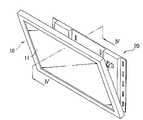
- FIG. 1is a perspective view of a display apparatus according to an embodiment of the present invention
- FIG. 2is a lateral view showing the display apparatus of FIG. 1 mounted on a wall;
- FIG. 3is an exploded view of the display apparatus of FIG. 1 ;
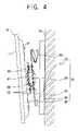
- FIG. 4is a sectional view of the display apparatus taken along line IV-IV in FIG. 1 ;
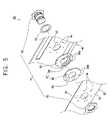
- FIG. 5is an exploded perspective view of a pivoting hinge of the display apparatus of FIG. 1 ;
- FIG. 6is an exploded perspective view of a link assembly of the display apparatus of FIG. 1 ;
- FIGS. 7 and 8show how the display apparatus of FIG. 1 is tilted
- FIGS. 9 and 10show how the display apparatus of FIG. 1 pivots.
- tiltingoccurs when the display rotates in forward and backward directions relative to a mounting surface
- pivotingoccurs when the display rotates in clockwise and counterclockwise directions relative to the mounting surface
- a display apparatuscomprises a display 10 to display a picture thereon, a mounting unit 20 to tiltably and pivotably mount the display 10 on a wall 25 .
- the display 10is provided with a thin display panel 11 such as a liquid crystal display (LCD), a plasma display panel (PDP) and the like, to display a picture, and a mounting protrusion 12 provided on a rear surface of the display 10 , to be inserted in the mounting unit 20 .
- a thin display panel 11such as a liquid crystal display (LCD), a plasma display panel (PDP) and the like, to display a picture
- a mounting protrusion 12provided on a rear surface of the display 10 , to be inserted in the mounting unit 20 .
- the mounting unit 20comprises: a supporting bracket 40 to support the display 10 ; a main body bracket 30 provided between the display 10 and the supporting bracket 40 to be connected to a rear surface of the display 10 ; an attaching bracket 50 provided between the supporting bracket 40 and the wall 25 to be attached to the wall 25 ; a tilting hinge 70 , which is provided between the supporting bracket 40 and the attaching bracket 50 , and by which the supporting bracket 40 tilts relative to the attaching bracket 50 , and therefore moves frontward and backward relative to the attaching bracket 50 and the wall 25 ; and a pivoting hinge 60 , which is provided between the main body bracket 30 and the supporting bracket 40 , and by which the main body bracket 30 pivots relative to the supporting bracket 40 , and therefore moves in clockwise and counterclockwise directions relative to the supporting bracket 40 and the wall 25 .
- the pivoting hinge 60comprises: a pivoting shaft 61 inserted into a central part of the supporting bracket 40 , a supporting disc 64 that is stationarily connected to the pivoting shaft 61 and connected to the supporting bracket 40 , a rotating disc 65 that is rotatably connected to the pivoting shaft 61 and connected to the main body bracket 30 , and a pivoting angle limiter 67 limiting a pivoting angle of the main body bracket 30 relative to the supporting bracket 40 .
- the pivoting shaft 61comprises a bolt 62 that passes through the central part of the supporting bracket 40 , is stationarily connected to the supporting disc 64 and rotatably connected to the rotating disc 65 , passes through the main body bracket 30 , and is inserted in a nut 63 .
- a part of a circumferential surface of the bolt 62 that is in contact with the main body bracket 30 and the rotating disc 65is not threaded.
- the pivoting shaft 61can be rotated relative to the main body bracket 30 due to the friction force between the pivoting shaft 61 and the rotating disc 65 , while the pivoting shaft 61 is stationarily connected to the supporting bracket 40 and the supporting disc 64 due to a threaded part of the pivoting shaft.
- a washer 22is provided between a head of the bolt 62 forming the pivoting shaft 61 and the supporting bracket 40 . Then, the washer 22 provides a sufficiently great friction force between the head of the bolt 62 and the supporting bracket 40 , thereby preventing the pivoting shaft 61 from sliding toward the main body bracket 30 or the supporting bracket 40 . Thus, the pivoting shaft 61 is not unnecessarily rotated when the display 10 is pivoted.
- the supporting disc 64 and the rotating disc 65are provided with a plurality of screw holes 66 a and 66 b , respectively.
- the supporting disc 64is connected to the supporting bracket 40 with screws 26 and the rotating disc 65 is connected to the main body bracket 30 with the screws 26 .
- the pivoting angle limiter 67comprises a supporting protrusion 68 positioned on the supporting disc 64 and a rotating protrusion 69 positioned on the rotating disc 65 .
- the surface of the supporting disc 64 having the supporting protrusion 68faces the rotating disc 65
- the surface of the rotating disc 65 having the rotating protrusion 69faces the supporting disc 64 .
- Each of the supporting protrusion 68 and the rotating protrusion 69is approximately equidistant from a center of the pivoting shaft 61 .
- the supporting protrusion 68meets with the rotating protrusion 69 , which limits the pivoting angle of the pivoting hinge 60 .
- the pivoting angle of the pivoting hinge 60is determined.
- the rotating disc 65 and the supporting disc 64are spaced with a distance corresponding to the thickness of one of the supporting protrusion 68 and the rotating protrusion 69 , whichever is thicker.
- the supporting protrusion 68is integrally formed with the supporting bracket 40 .
- the rotating protrusion 69is integrally formed with either the display 10 or the main body bracket 30 .
- the supporting protrusion 68is an arc of about 180° relative to the center of the supporting disc 64
- the rotating protrusion 69is an arc of about 90° relative to the center of the rotating disc 65 .
- the display 10pivots within a pivoting angle of approximately 90°.
- the display 10may pivot with more stability due to the pivoting angle limiter having the structure described above.
- lubricating materialsuch as oil is provided between the pivoting shaft 61 and the rotating disc 65 , between the supporting protrusion 68 and the rotating disc 65 , and between the rotating protrusion 69 and the supporting disc 64 .
- the main body bracket 30comprises: connecting parts 31 that connect to a rear surface of the display 10 ; a bracket main body 35 having a shaft accommodating hole 33 in which the pivoting shaft 61 is inserted; and main body holes 34 positioned corresponding to the screw holes 66 b positioned on the rotating disc 65 , through which the screws 26 are inserted in the rotating disc 65 .
- Each of the connecting parts 31 of the main body bracket 30comprises mounting protrusion holes 32 to accommodate the mounting protrusion 12 positioned on the rear of the display 10 .
- Each of the protrusions 12 positioned on the rear of the display 10is inserted in the mounting protrusion hole 32 , so that the display 10 is detachably connected with the main body bracket 30 .
- the main body bracket 30is added between the display 10 and the supporting bracket 40 .
- the pivoting hinge 60is directly connected to the rear surface of the display 10 , so that the main body bracket 30 is not required.
- the supporting bracket 40comprises: a pivoting shaft hole 43 to accommodate the pivoting shaft 61 ; supporting holes 44 , through which the supporting bracket 40 is connected with the supporting disk 64 with the screws 26 , and which are positioned corresponding to the screw holes 66 a of the supporting disc 64 ; second flanges 46 having second pin connecting holes 47 rotatably connected with second pin accommodating holes 84 of a second link 82 (to be described later) connected with the tilting hinge 70 ; and supporting flanges 48 having lower pin connecting holes 49 rotatably connected with lower pin accommodating holes 59 of the attaching bracket 50 .
- the attaching bracket 50comprises: first flanges 56 provided on an upper part of the attaching bracket 50 and having first pin connecting holes 57 rotatably connected with first pin accommodating holes 83 of a first link 81 of the tilting hinge 70 (to be described later), and attaching flanges 58 (to be described later) provided on a lower part of the attaching bracket 50 and having the lower pin accommodating holes 59 .
- the attaching bracket 50is attached on the wall 25 to support the display 10 .
- the first link 81 and a lower hinge 71 of the tilting hinge 70are directly mounted on the wall 25 , so that the attaching bracket 50 is not required.
- the tilting hinge 70comprises the lower hinge 71 provided on a lower part of the supporting bracket 40 to tilt the supporting bracket 40 relative to the attaching bracket 50 and a link assembly 80 provided on an upper part of the supporting bracket 40 and linking the supporting bracket 40 and the attaching bracket 50 , to adjust a space between the supporting bracket 40 and the attaching bracket 50 .
- the lower hinge 71comprises: the supporting flanges 48 having the lower pin connecting holes 49 of the supporting bracket 40 , the attaching flanges 58 having the lower pin accommodating holes 59 of the attaching bracket 50 , and lower hinge pins (or attaching hinge pins) 72 rotatably connecting the lower pin connecting holes 49 and the lower pin accommodating holes 59 .
- the link assembly 80comprises: the first link 81 provided on an upper part of the attaching bracket 50 , the second link 82 provided on an upper part of the rear of the supporting bracket 40 and connected with the first link 81 to adjust the space between the supporting bracket 40 and the attaching bracket 50 , an elastic member (torsion spring) 91 provided between the first link 81 and the second link 82 and having an elasticity to restore the supporting bracket 40 to the attaching bracket 50 , and a friction part 92 provided between the first link 81 and the second link 82 and producing a rotation friction therebetween.
- the rotation friction of the friction part 92is preferably larger than the elasticity of the torsion spring 91 .
- the first link 81has a “U” shaped cross section and comprises a first end having the first pin accommodating holes 83 rotatably connected with the first pin inserting holes 57 of the attaching bracket 50 with a first hinge pin 85 , and a second end having bolt connecting holes 87 rotatably connected with the second link 82 .
- the second link 82comprises a first end having the second pin accommodating holes 84 rotatably connected with the second pin connecting holes 47 of the supporting bracket 40 with the second hinge pin 86 , and a second end having bolt accommodating holes 88 rotatably connected with the bolt connecting holes 87 of the first link 81 .
- the second link 82has a “U” shaped cross section and is larger than the first link 81 in width, so that the first link 81 can be folded and accommodated in the second link 82 .
- the torsion spring 91is installed on a connecting bolt 93 of the friction part 92 (to be described later).
- the torsion springhas a first end coupled to the first link 81 and a second end coupled to the second link 82 .
- the torsion springelastically draws the second link 82 to the first link 81 .
- the torsion spring 91elastically restores the display 10 to the wall 25 .
- the elasticity of the torsion spring 91is approximately equal to the torque produced by the weight of the display 10 about the lower hinge 71 .
- the friction part 92comprises: the connecting bolt 93 passing through the bolt connecting holes 87 of the first link 81 and the bolt accommodating holes 88 of the second link 82 to be inserted in the torsion spring 91 , a connecting nut 94 connected with the connecting bolt 93 , and a plurality of washers 24 provided between a head of the connecting bolt 93 and the connecting nut 94 .
- the connecting bolt 93is tightened with the connecting nut 94
- the friction part 92produces the rotation friction between the first link 81 and the second link 82 .
- the rotation frictionis larger than the elasticity of the torsion spring 91 .
- the friction part 92is provided between the first and second links 81 and 82 to produce the rotation friction. But according to another aspect, the friction part 92 is provided between the attaching bracket 50 and the first link 81 . According to yet another aspect, the friction part 92 is provided between the supporting bracket 40 and the second link 82 . According to still yet another aspect, the friction part 92 is provided on more than one of the connections between the supporting bracket 40 , the second link 82 , the first link 81 , and the attaching bracket 50 .
- the torsion spring 91is provided in the friction part 92 between the first and second links 81 and 82 . But, according to another aspect, the torsion spring 91 is provided at any place within which the first and second links 81 and 82 are rotated between the supporting bracket 40 and the attaching bracket 50 . According to one aspect, the torsion spring 91 is a flat spring. According to another aspect, the torsion spring 91 is a coil spring. According to yet another aspect, the torsion spring may, either additionally or instead, be positioned on the lower hinge pin 72 .
- two lower hinges 71are provided.
- two link assemblies 80are provided. It will be readily recognized, however, that there may be only one lower hinge 71 and one link assembly 80 , or there may be more than two lower hinges 71 and more than two link assemblies 80 .
- the display 10is rotated relative to the lower hinge 71 if the user pulls the display 10 shown in FIG. 7 toward the user with a predetermined amount of force.
- the elasticity of the torsion spring 91 elastically restoring the display 10 toward the wall 25is applied, which prevents the display from suddenly rotating toward the user.
- the displaying apparatuscan remain unfolded due to the rotation friction of the friction part 92 .
- a stopper(not shown) is provided between the first link 81 and the second link 82 and/or at the lower hinge 71 , to prevent the display 10 from rotating farther than a predetermined rotation angle.
- the display apparatus mounted on the wallcan not only be tilted, but also pivoted, so that the viewing angle of the display can be adjusted as desired.
- the structure of the mounting unit tiltably and pivotably supporting the display on the wallcan be simplified, and a large display apparatus can be supported with stability.
Landscapes
- Engineering & Computer Science (AREA)
- General Engineering & Computer Science (AREA)
- Mechanical Engineering (AREA)
- Multimedia (AREA)
- Signal Processing (AREA)
- Devices For Indicating Variable Information By Combining Individual Elements (AREA)
Abstract
Description
Claims (35)
Applications Claiming Priority (2)
| Application Number | Priority Date | Filing Date | Title |
|---|---|---|---|
| KR2003-75084 | 2003-10-27 | ||
| KR1020030075084AKR100753607B1 (en) | 2003-10-27 | 2003-10-27 | Display device |
Publications (2)
| Publication Number | Publication Date |
|---|---|
| US20050087666A1 US20050087666A1 (en) | 2005-04-28 |
| US7334765B2true US7334765B2 (en) | 2008-02-26 |
Family
ID=34511103
Family Applications (1)
| Application Number | Title | Priority Date | Filing Date |
|---|---|---|---|
| US10/973,238Expired - Fee RelatedUS7334765B2 (en) | 2003-10-27 | 2004-10-27 | Display apparatus |
Country Status (3)
| Country | Link |
|---|---|
| US (1) | US7334765B2 (en) |
| KR (1) | KR100753607B1 (en) |
| CN (1) | CN100574585C (en) |
Cited By (20)
| Publication number | Priority date | Publication date | Assignee | Title |
|---|---|---|---|---|
| US20060237599A1 (en)* | 2005-04-22 | 2006-10-26 | John Ternus | Flat panel display including a hinge assembly |
| US20070041213A1 (en)* | 2005-08-18 | 2007-02-22 | Avf Group Limited | Adjustable mount |
| US20070041150A1 (en)* | 2005-08-18 | 2007-02-22 | Avf Group Limited | Tilting mechanism |
| US20070211417A1 (en)* | 2006-03-01 | 2007-09-13 | Sanyo Electric Co., Ltd. | Video display |
| US20070221808A1 (en)* | 2006-03-24 | 2007-09-27 | Keyang Electric Machinery Co. Ltd. | Automatic wall mounting system for wall-mounted TV |
| US20080078907A1 (en)* | 2006-09-11 | 2008-04-03 | Tom Huang | Mounting device capable of positioning a display device at an adjusted angle |
| US20080185497A1 (en)* | 2007-02-06 | 2008-08-07 | Kernan Technology Co., Ltd. | Carrier device for monitor |
| US20090057513A1 (en)* | 2004-09-29 | 2009-03-05 | Huai Wu | Grade control apparatus for display set used in tapestry |
| US20100038501A1 (en)* | 2008-08-18 | 2010-02-18 | Oh Sung I | Low Profile Tilt Mount |
| US20100102181A1 (en)* | 2008-02-04 | 2010-04-29 | Oh Sung I | Swivel Mount System For A Monitor |
| US20100172072A1 (en)* | 2009-01-05 | 2010-07-08 | Peerless Industries, Inc. | Multiple arm articulating mounting system |
| US20100280746A1 (en)* | 2008-01-22 | 2010-11-04 | Martin Riddiford | Navigation assembly, a foldable mount and a navigation assembly including such a mount |
| US20110141671A1 (en)* | 2009-12-10 | 2011-06-16 | Hitachi Consumer Electronics Co., Ltd. | Display apparatus |
| US20110211301A1 (en)* | 2010-02-26 | 2011-09-01 | Sanyo Electric Co., Ltd. | Electronic device and wall hanging structure of electronic device |
| US20120061543A1 (en)* | 2010-09-09 | 2012-03-15 | Landa Juan | Adjustable flat-panel display mount |
| US20170238430A1 (en)* | 2016-02-16 | 2017-08-17 | Jslcd Co., Ltd. | Display device equipped with frame assembly |
| US10400946B2 (en) | 2010-07-08 | 2019-09-03 | Southco, Inc. | Display support apparatus |
| US11131423B2 (en) | 2016-03-07 | 2021-09-28 | Southco, Inc. | Display support arm assembly for mounting a display |
| US11653456B2 (en)* | 2018-07-12 | 2023-05-16 | Lg Electronics Inc. | Display device |
| US20230271075A1 (en)* | 2022-02-25 | 2023-08-31 | Equip Products, Inc. | Control Panel Mount for Exercise Machine |
Families Citing this family (30)
| Publication number | Priority date | Publication date | Assignee | Title |
|---|---|---|---|---|
| USD544868S1 (en)* | 2005-05-02 | 2007-06-19 | Sony Corporation | Supporter for monitor or television |
| USD568320S1 (en)* | 2005-05-02 | 2008-05-06 | Sony Corporation | Supporter for monitor or television |
| USD562829S1 (en)* | 2005-05-02 | 2008-02-26 | Sony Corporation | Supporter for monitor/television |
| USD562830S1 (en)* | 2005-05-02 | 2008-02-26 | Sony Corporation | Supporter for monitor/television |
| USD562831S1 (en)* | 2005-05-02 | 2008-02-26 | Sony Corporation | Supporter for monitor/television |
| KR100743746B1 (en) | 2005-07-08 | 2007-07-27 | 엘지전자 주식회사 | Display device angle adjuster |
| US20070023599A1 (en)* | 2005-07-26 | 2007-02-01 | Dale Fedewa | Adjustable display mount apparatus and system |
| KR101145211B1 (en)* | 2005-11-05 | 2012-05-25 | 삼성전자주식회사 | Display apparatus |
| KR101135902B1 (en)* | 2005-11-12 | 2012-04-19 | 삼성전자주식회사 | Supporting apparatus for display |
| KR100838591B1 (en)* | 2007-01-08 | 2008-06-19 | 삼성전기주식회사 | Display rotating device |
| US7661642B2 (en)* | 2007-10-11 | 2010-02-16 | Clo Systems | Motorized mount to pivot a monitor |
| KR20090040683A (en)* | 2007-10-22 | 2009-04-27 | 엘지전자 주식회사 | Supporting device for flat panel display devices |
| USD602923S1 (en) | 2008-01-04 | 2009-10-27 | Milestone Av Technologies Llc | Dual position mount for an electronic display |
| KR100922872B1 (en)* | 2008-01-07 | 2009-10-20 | 곽수만 | Arm stand for display unit |
| US8313068B2 (en)* | 2008-05-08 | 2012-11-20 | Samsung Electronics Co., Ltd. | Lifting device for display apparatus |
| CN101725801B (en)* | 2008-10-17 | 2012-08-29 | 鸿富锦精密工业(深圳)有限公司 | Rotational structure |
| JP4653847B1 (en)* | 2009-09-30 | 2011-03-16 | 株式会社東芝 | Display device |
| CN102032423B (en)* | 2009-09-30 | 2014-03-05 | 深圳富泰宏精密工业有限公司 | Support mechanism and electronic device applying same |
| KR20110054349A (en)* | 2009-11-17 | 2011-05-25 | 배성은 | Flat TV Vertical Rotating Mechanism |
| JP5716461B2 (en)* | 2011-03-03 | 2015-05-13 | ブラザー工業株式会社 | Rotation operation device and image recording device |
| CN102322560B (en)* | 2011-08-23 | 2013-01-02 | 苏州佳世达电通有限公司 | Electronic module and buckling mechanism thereof |
| KR101868847B1 (en)* | 2011-12-30 | 2018-06-21 | 삼성전자주식회사 | Supporting device for display unit |
| DE112016004031B4 (en) | 2015-09-30 | 2022-10-13 | Fujifilm Corporation | imaging device |
| CN106122733B (en)* | 2016-08-30 | 2019-05-07 | 南京国豪家装饰设计有限公司 | A kind of display screen suspension arrangement |
| CN108022508A (en)* | 2017-12-18 | 2018-05-11 | 重庆蜀腾科技有限公司 | A kind of rotating electron class board |
| CN108443973A (en)* | 2018-05-31 | 2018-08-24 | 珠海格力电器股份有限公司 | Air conditioner wall hanging plate, air conditioner indoor unit assembly and air conditioner |
| US11215313B1 (en)* | 2019-05-24 | 2022-01-04 | Snap One, Llc | Display mounts and related systems and methods |
| US12306665B2 (en) | 2021-07-13 | 2025-05-20 | Samsung Electronics Co., Ltd | Display apparatus |
| KR20230011020A (en)* | 2021-07-13 | 2023-01-20 | 삼성전자주식회사 | Display apparatus |
| US20250081369A1 (en)* | 2022-10-07 | 2025-03-06 | Google Llc | Folding portable display device |
Citations (20)
| Publication number | Priority date | Publication date | Assignee | Title |
|---|---|---|---|---|
| JPH11272187A (en) | 1998-03-25 | 1999-10-08 | Kato Electrical Mach Co Ltd | Tilt hinge |
| US5975472A (en)* | 1998-11-19 | 1999-11-02 | Hung; Chin-Jui | Video display support having angle adjustment |
| US6019332A (en) | 1996-06-07 | 2000-02-01 | Ergotron, Inc. | Pivot/ratchet assembly and support system |
| JP2000333101A (en) | 1999-05-20 | 2000-11-30 | Nanao Corp | Vertical turning support mechanism for video monitor |
| JP2001128088A (en) | 1999-10-29 | 2001-05-11 | Kato Electrical Mach Co Ltd | Screen angle adjuster for display device |
| US20020011544A1 (en)* | 2000-03-30 | 2002-01-31 | Bosson Peter Thomas | Display device support system |
| US6478275B1 (en)* | 2001-08-31 | 2002-11-12 | Min Hwa Huang | Support device for monitor, displayer or other object |
| JP2002366047A (en) | 2001-06-04 | 2002-12-20 | Kato Electrical Mach Co Ltd | Screen angle adjusting device for display device |
| KR20030012977A (en) | 2001-08-06 | 2003-02-14 | 민정 | Hanging system for television |
| KR20030014494A (en) | 2001-08-11 | 2003-02-19 | 삼성전자주식회사 | Coating apparatus using a heat source |
| KR20030025988A (en) | 2001-09-24 | 2003-03-31 | 민정 | Hanging system for television |
| US20030075649A1 (en)* | 2001-10-24 | 2003-04-24 | Samsung Electronics Co., Ltd. | LCD monitor stand |
| US6554238B1 (en)* | 1999-11-18 | 2003-04-29 | Claiteal Pty. Limited | Support arm for visual display unit |
| KR20030056775A (en) | 2001-12-28 | 2003-07-04 | 엘지전자 주식회사 | Hinge assembly for thin-type display device |
| US6874743B2 (en)* | 2001-12-13 | 2005-04-05 | Murakami Corporation | Direction regulator of display |
| US6886701B2 (en)* | 2002-05-28 | 2005-05-03 | Samsung Electronics Co., Ltd | Display apparatus having a structure for wall mounting |
| US6905101B1 (en)* | 2002-06-11 | 2005-06-14 | Chief Manufacturing Inc. | Adjustable, self-balancing flat panel display mounting system |
| US7028961B1 (en)* | 2003-05-30 | 2006-04-18 | Csav, Inc. | Self-balancing adjustable flat panel mounting system |
| US7097143B2 (en)* | 2002-09-19 | 2006-08-29 | Samsung Electronics Co., Ltd. | Installation equipment for display main body and jig for installation equipment |
| US7178775B2 (en)* | 2003-01-09 | 2007-02-20 | Csav, Inc. | Adjustable tilt mount |
Family Cites Families (5)
| Publication number | Priority date | Publication date | Assignee | Title |
|---|---|---|---|---|
| US6505988B1 (en) | 1999-06-02 | 2003-01-14 | Innovative Office Products, Inc. | Tilter for positioning electronic devices |
| US6189842B1 (en)* | 1999-06-21 | 2001-02-20 | Palo Alto Design Group | Tilt and swivel adjustment of flat panel display having detents for landscape and portrait positions and kickout for preventing contact between flat panel display and base |
| KR100381542B1 (en)* | 2000-07-28 | 2003-04-30 | 주식회사 에이텍시스템 | An angle control device of LCD monitor for computer system |
| KR20020073875A (en)* | 2001-03-16 | 2002-09-28 | 엘지전자 주식회사 | Fixing and tilting control apparatus of monitor for wall tapestry |
| KR20030046900A (en)* | 2001-12-07 | 2003-06-18 | 동오정밀 주식회사 | Angle control apparatus for LCD monitor |
- 2003
- 2003-10-27KRKR1020030075084Apatent/KR100753607B1/ennot_activeExpired - Fee Related
- 2004
- 2004-10-27USUS10/973,238patent/US7334765B2/ennot_activeExpired - Fee Related
- 2004-10-27CNCNB2004100863892Apatent/CN100574585C/ennot_activeExpired - Fee Related
Patent Citations (20)
| Publication number | Priority date | Publication date | Assignee | Title |
|---|---|---|---|---|
| US6019332A (en) | 1996-06-07 | 2000-02-01 | Ergotron, Inc. | Pivot/ratchet assembly and support system |
| JPH11272187A (en) | 1998-03-25 | 1999-10-08 | Kato Electrical Mach Co Ltd | Tilt hinge |
| US5975472A (en)* | 1998-11-19 | 1999-11-02 | Hung; Chin-Jui | Video display support having angle adjustment |
| JP2000333101A (en) | 1999-05-20 | 2000-11-30 | Nanao Corp | Vertical turning support mechanism for video monitor |
| JP2001128088A (en) | 1999-10-29 | 2001-05-11 | Kato Electrical Mach Co Ltd | Screen angle adjuster for display device |
| US6554238B1 (en)* | 1999-11-18 | 2003-04-29 | Claiteal Pty. Limited | Support arm for visual display unit |
| US20020011544A1 (en)* | 2000-03-30 | 2002-01-31 | Bosson Peter Thomas | Display device support system |
| JP2002366047A (en) | 2001-06-04 | 2002-12-20 | Kato Electrical Mach Co Ltd | Screen angle adjusting device for display device |
| KR20030012977A (en) | 2001-08-06 | 2003-02-14 | 민정 | Hanging system for television |
| KR20030014494A (en) | 2001-08-11 | 2003-02-19 | 삼성전자주식회사 | Coating apparatus using a heat source |
| US6478275B1 (en)* | 2001-08-31 | 2002-11-12 | Min Hwa Huang | Support device for monitor, displayer or other object |
| KR20030025988A (en) | 2001-09-24 | 2003-03-31 | 민정 | Hanging system for television |
| US20030075649A1 (en)* | 2001-10-24 | 2003-04-24 | Samsung Electronics Co., Ltd. | LCD monitor stand |
| US6874743B2 (en)* | 2001-12-13 | 2005-04-05 | Murakami Corporation | Direction regulator of display |
| KR20030056775A (en) | 2001-12-28 | 2003-07-04 | 엘지전자 주식회사 | Hinge assembly for thin-type display device |
| US6886701B2 (en)* | 2002-05-28 | 2005-05-03 | Samsung Electronics Co., Ltd | Display apparatus having a structure for wall mounting |
| US6905101B1 (en)* | 2002-06-11 | 2005-06-14 | Chief Manufacturing Inc. | Adjustable, self-balancing flat panel display mounting system |
| US7097143B2 (en)* | 2002-09-19 | 2006-08-29 | Samsung Electronics Co., Ltd. | Installation equipment for display main body and jig for installation equipment |
| US7178775B2 (en)* | 2003-01-09 | 2007-02-20 | Csav, Inc. | Adjustable tilt mount |
| US7028961B1 (en)* | 2003-05-30 | 2006-04-18 | Csav, Inc. | Self-balancing adjustable flat panel mounting system |
Cited By (36)
| Publication number | Priority date | Publication date | Assignee | Title |
|---|---|---|---|---|
| US20090057513A1 (en)* | 2004-09-29 | 2009-03-05 | Huai Wu | Grade control apparatus for display set used in tapestry |
| US8387928B2 (en) | 2005-04-22 | 2013-03-05 | Apple Inc. | Flat panel display including a hinge assembly |
| US8820687B2 (en) | 2005-04-22 | 2014-09-02 | Apple Inc. | Flat panel display including a hinge assembly |
| US8118269B2 (en)* | 2005-04-22 | 2012-02-21 | Apple Inc. | Flat panel display including a hinge assembly |
| US20060237599A1 (en)* | 2005-04-22 | 2006-10-26 | John Ternus | Flat panel display including a hinge assembly |
| US20090230270A1 (en)* | 2005-04-22 | 2009-09-17 | Apple Inc. | Flat panel display including a hinge assembly |
| US7857270B2 (en) | 2005-08-18 | 2010-12-28 | Avf Group Limited | Tilting mechanism |
| US7918426B2 (en)* | 2005-08-18 | 2011-04-05 | Avf Group Limited | Adjustable mount |
| US20070041213A1 (en)* | 2005-08-18 | 2007-02-22 | Avf Group Limited | Adjustable mount |
| US20070041150A1 (en)* | 2005-08-18 | 2007-02-22 | Avf Group Limited | Tilting mechanism |
| US7561423B2 (en)* | 2006-03-01 | 2009-07-14 | Sanyo Electric Co., Ltd. | Video display |
| US20070211417A1 (en)* | 2006-03-01 | 2007-09-13 | Sanyo Electric Co., Ltd. | Video display |
| US20070221808A1 (en)* | 2006-03-24 | 2007-09-27 | Keyang Electric Machinery Co. Ltd. | Automatic wall mounting system for wall-mounted TV |
| US20080078907A1 (en)* | 2006-09-11 | 2008-04-03 | Tom Huang | Mounting device capable of positioning a display device at an adjusted angle |
| US20080185497A1 (en)* | 2007-02-06 | 2008-08-07 | Kernan Technology Co., Ltd. | Carrier device for monitor |
| US7413152B1 (en)* | 2007-02-06 | 2008-08-19 | Kernan Technology Co., Ltd. | Carrier device for monitor |
| US8814116B2 (en) | 2008-01-22 | 2014-08-26 | Tomtom International B.V. | Navigation assembly, a foldable mount and a navigation assembly including such a mount |
| US20100280746A1 (en)* | 2008-01-22 | 2010-11-04 | Martin Riddiford | Navigation assembly, a foldable mount and a navigation assembly including such a mount |
| US20100102181A1 (en)* | 2008-02-04 | 2010-04-29 | Oh Sung I | Swivel Mount System For A Monitor |
| US20100038501A1 (en)* | 2008-08-18 | 2010-02-18 | Oh Sung I | Low Profile Tilt Mount |
| US20100172072A1 (en)* | 2009-01-05 | 2010-07-08 | Peerless Industries, Inc. | Multiple arm articulating mounting system |
| US20110141671A1 (en)* | 2009-12-10 | 2011-06-16 | Hitachi Consumer Electronics Co., Ltd. | Display apparatus |
| US8405960B2 (en)* | 2009-12-10 | 2013-03-26 | Hitachi Consumer Electronics Co., Ltd. | Display apparatus |
| US20110211301A1 (en)* | 2010-02-26 | 2011-09-01 | Sanyo Electric Co., Ltd. | Electronic device and wall hanging structure of electronic device |
| US8482907B2 (en)* | 2010-02-26 | 2013-07-09 | Sanyo Electric Co., Ltd. | Electronic device and wall hanging structure of electronic device |
| US10400946B2 (en) | 2010-07-08 | 2019-09-03 | Southco, Inc. | Display support apparatus |
| US20120061543A1 (en)* | 2010-09-09 | 2012-03-15 | Landa Juan | Adjustable flat-panel display mount |
| US20170238430A1 (en)* | 2016-02-16 | 2017-08-17 | Jslcd Co., Ltd. | Display device equipped with frame assembly |
| US9826648B2 (en)* | 2016-02-16 | 2017-11-21 | Jslcd Co., Ltd. | Display device equipped with frame assembly |
| US11131423B2 (en) | 2016-03-07 | 2021-09-28 | Southco, Inc. | Display support arm assembly for mounting a display |
| US11506329B2 (en) | 2016-03-07 | 2022-11-22 | Southco, Inc. | Display support arm assembly for mounting a display |
| US11536416B2 (en) | 2016-03-07 | 2022-12-27 | Southco, Inc. | Display support arm assembly for mounting a display |
| US11543070B2 (en) | 2016-03-07 | 2023-01-03 | Southco, Inc. | Display support arm assembly for mounting a display |
| US11653456B2 (en)* | 2018-07-12 | 2023-05-16 | Lg Electronics Inc. | Display device |
| US20230271075A1 (en)* | 2022-02-25 | 2023-08-31 | Equip Products, Inc. | Control Panel Mount for Exercise Machine |
| US12343611B2 (en)* | 2022-02-25 | 2025-07-01 | Equip Products, Inc. | Control panel mount for exercise machine |
Also Published As
| Publication number | Publication date |
|---|---|
| US20050087666A1 (en) | 2005-04-28 |
| KR20050039984A (en) | 2005-05-03 |
| KR100753607B1 (en) | 2007-08-30 |
| CN1612681A (en) | 2005-05-04 |
| CN100574585C (en) | 2009-12-23 |
Similar Documents
| Publication | Publication Date | Title |
|---|---|---|
| US7334765B2 (en) | Display apparatus | |
| KR100512718B1 (en) | Monitor | |
| US6912120B2 (en) | Tilting and shielding apparatus of monitor | |
| US7798460B2 (en) | Apparatus to support a display device | |
| US7567436B2 (en) | Monitor | |
| US20080007906A1 (en) | Hinge assembly with stop and display monitor having same | |
| US7640628B2 (en) | Hinge assembly for flat display monitor | |
| US7770856B2 (en) | Thin computer monitor support apparatus | |
| US7698784B2 (en) | Hinge assembly for display monitor | |
| US20090101777A1 (en) | Wall mount supporting apparatus of flat panel display device | |
| US6453509B1 (en) | Hinge arrangement for a display apparatus | |
| CN100446543C (en) | Hinge Assemblies for Flat Panel Displays | |
| US7494099B2 (en) | Wall mount usable with display apparatus | |
| US7712187B2 (en) | Hinge assembly and display monitor with the same | |
| US20050258319A1 (en) | Monitor apparatus | |
| US20020002759A1 (en) | Hinge assembly for LCD monitor | |
| US8196875B2 (en) | Support stand with intermediate connecting assembly | |
| US20070136995A1 (en) | Hinge assembly for flat display monitor | |
| US20070136994A1 (en) | Hinge assembly for flat display monitor | |
| US7283354B2 (en) | Monitor apparatus | |
| US20030042385A1 (en) | Liquid crystal display with a ball-and-socket mounting joint | |
| US20070215761A1 (en) | Display support mechanism | |
| US7353569B2 (en) | Hinge assembly for a flat display monitor | |
| KR100566476B1 (en) | apparatus for an inclination motion | |
| TWI399163B (en) | Hinge assembly |
Legal Events
| Date | Code | Title | Description |
|---|---|---|---|
| AS | Assignment | Owner name:SAMSUNG ELECTRONICS CO., LTD., KOREA, REPUBLIC OF Free format text:ASSIGNMENT OF ASSIGNORS INTEREST;ASSIGNOR:HWANG, JUNG-HO;REEL/FRAME:015934/0631 Effective date:20041025 | |
| FEPP | Fee payment procedure | Free format text:PAYOR NUMBER ASSIGNED (ORIGINAL EVENT CODE: ASPN); ENTITY STATUS OF PATENT OWNER: LARGE ENTITY | |
| STCF | Information on status: patent grant | Free format text:PATENTED CASE | |
| FEPP | Fee payment procedure | Free format text:PAYER NUMBER DE-ASSIGNED (ORIGINAL EVENT CODE: RMPN); ENTITY STATUS OF PATENT OWNER: LARGE ENTITY Free format text:PAYOR NUMBER ASSIGNED (ORIGINAL EVENT CODE: ASPN); ENTITY STATUS OF PATENT OWNER: LARGE ENTITY | |
| FPAY | Fee payment | Year of fee payment:4 | |
| FPAY | Fee payment | Year of fee payment:8 | |
| FEPP | Fee payment procedure | Free format text:MAINTENANCE FEE REMINDER MAILED (ORIGINAL EVENT CODE: REM.); ENTITY STATUS OF PATENT OWNER: LARGE ENTITY | |
| LAPS | Lapse for failure to pay maintenance fees | Free format text:PATENT EXPIRED FOR FAILURE TO PAY MAINTENANCE FEES (ORIGINAL EVENT CODE: EXP.); ENTITY STATUS OF PATENT OWNER: LARGE ENTITY | |
| STCH | Information on status: patent discontinuation | Free format text:PATENT EXPIRED DUE TO NONPAYMENT OF MAINTENANCE FEES UNDER 37 CFR 1.362 | |
| FP | Lapsed due to failure to pay maintenance fee | Effective date:20200226 |