US7334650B2 - Apparatus and methods for drilling a wellbore using casing - Google Patents
Apparatus and methods for drilling a wellbore using casingDownload PDFInfo
- Publication number
- US7334650B2 US7334650B2US10/772,217US77221704AUS7334650B2US 7334650 B2US7334650 B2US 7334650B2US 77221704 AUS77221704 AUS 77221704AUS 7334650 B2US7334650 B2US 7334650B2
- Authority
- US
- United States
- Prior art keywords
- casing
- drilling
- wellbore
- string
- fluid
- Prior art date
- Legal status (The legal status is an assumption and is not a legal conclusion. Google has not performed a legal analysis and makes no representation as to the accuracy of the status listed.)
- Expired - Fee Related, expires
Links
Images


Classifications
- E—FIXED CONSTRUCTIONS
- E21—EARTH OR ROCK DRILLING; MINING
- E21B—EARTH OR ROCK DRILLING; OBTAINING OIL, GAS, WATER, SOLUBLE OR MELTABLE MATERIALS OR A SLURRY OF MINERALS FROM WELLS
- E21B43/00—Methods or apparatus for obtaining oil, gas, water, soluble or meltable materials or a slurry of minerals from wells
- E21B43/02—Subsoil filtering
- E21B43/10—Setting of casings, screens, liners or the like in wells
- E21B43/103—Setting of casings, screens, liners or the like in wells of expandable casings, screens, liners, or the like
- E21B43/105—Expanding tools specially adapted therefor
- E—FIXED CONSTRUCTIONS
- E21—EARTH OR ROCK DRILLING; MINING
- E21B—EARTH OR ROCK DRILLING; OBTAINING OIL, GAS, WATER, SOLUBLE OR MELTABLE MATERIALS OR A SLURRY OF MINERALS FROM WELLS
- E21B10/00—Drill bits
- E21B10/60—Drill bits characterised by conduits or nozzles for drilling fluids
- E21B10/61—Drill bits characterised by conduits or nozzles for drilling fluids characterised by the nozzle structure
- E—FIXED CONSTRUCTIONS
- E21—EARTH OR ROCK DRILLING; MINING
- E21B—EARTH OR ROCK DRILLING; OBTAINING OIL, GAS, WATER, SOLUBLE OR MELTABLE MATERIALS OR A SLURRY OF MINERALS FROM WELLS
- E21B17/00—Drilling rods or pipes; Flexible drill strings; Kellies; Drill collars; Sucker rods; Cables; Casings; Tubings
- E21B17/14—Casing shoes for the protection of the bottom of the casing
- E—FIXED CONSTRUCTIONS
- E21—EARTH OR ROCK DRILLING; MINING
- E21B—EARTH OR ROCK DRILLING; OBTAINING OIL, GAS, WATER, SOLUBLE OR MELTABLE MATERIALS OR A SLURRY OF MINERALS FROM WELLS
- E21B21/00—Methods or apparatus for flushing boreholes, e.g. by use of exhaust air from motor
- E21B21/10—Valve arrangements in drilling-fluid circulation systems
- E21B21/103—Down-hole by-pass valve arrangements, i.e. between the inside of the drill string and the annulus
- E—FIXED CONSTRUCTIONS
- E21—EARTH OR ROCK DRILLING; MINING
- E21B—EARTH OR ROCK DRILLING; OBTAINING OIL, GAS, WATER, SOLUBLE OR MELTABLE MATERIALS OR A SLURRY OF MINERALS FROM WELLS
- E21B33/00—Sealing or packing boreholes or wells
- E21B33/10—Sealing or packing boreholes or wells in the borehole
- E21B33/13—Methods or devices for cementing, for plugging holes, crevices or the like
- E21B33/14—Methods or devices for cementing, for plugging holes, crevices or the like for cementing casings into boreholes
- E—FIXED CONSTRUCTIONS
- E21—EARTH OR ROCK DRILLING; MINING
- E21B—EARTH OR ROCK DRILLING; OBTAINING OIL, GAS, WATER, SOLUBLE OR MELTABLE MATERIALS OR A SLURRY OF MINERALS FROM WELLS
- E21B41/00—Equipment or details not covered by groups E21B15/00 - E21B40/00
- E21B41/0078—Nozzles used in boreholes
- E—FIXED CONSTRUCTIONS
- E21—EARTH OR ROCK DRILLING; MINING
- E21B—EARTH OR ROCK DRILLING; OBTAINING OIL, GAS, WATER, SOLUBLE OR MELTABLE MATERIALS OR A SLURRY OF MINERALS FROM WELLS
- E21B47/00—Survey of boreholes or wells
- E21B47/01—Devices for supporting measuring instruments on drill bits, pipes, rods or wirelines; Protecting measuring instruments in boreholes against heat, shock, pressure or the like
- E—FIXED CONSTRUCTIONS
- E21—EARTH OR ROCK DRILLING; MINING
- E21B—EARTH OR ROCK DRILLING; OBTAINING OIL, GAS, WATER, SOLUBLE OR MELTABLE MATERIALS OR A SLURRY OF MINERALS FROM WELLS
- E21B7/00—Special methods or apparatus for drilling
- E21B7/04—Directional drilling
- E21B7/06—Deflecting the direction of boreholes
- E21B7/065—Deflecting the direction of boreholes using oriented fluid jets
- E—FIXED CONSTRUCTIONS
- E21—EARTH OR ROCK DRILLING; MINING
- E21B—EARTH OR ROCK DRILLING; OBTAINING OIL, GAS, WATER, SOLUBLE OR MELTABLE MATERIALS OR A SLURRY OF MINERALS FROM WELLS
- E21B7/00—Special methods or apparatus for drilling
- E21B7/18—Drilling by liquid or gas jets, with or without entrained pellets
- E—FIXED CONSTRUCTIONS
- E21—EARTH OR ROCK DRILLING; MINING
- E21B—EARTH OR ROCK DRILLING; OBTAINING OIL, GAS, WATER, SOLUBLE OR MELTABLE MATERIALS OR A SLURRY OF MINERALS FROM WELLS
- E21B7/00—Special methods or apparatus for drilling
- E21B7/20—Driving or forcing casings or pipes into boreholes, e.g. sinking; Simultaneously drilling and casing boreholes
- E21B7/208—Driving or forcing casings or pipes into boreholes, e.g. sinking; Simultaneously drilling and casing boreholes using down-hole drives
- B—PERFORMING OPERATIONS; TRANSPORTING
- B05—SPRAYING OR ATOMISING IN GENERAL; APPLYING FLUENT MATERIALS TO SURFACES, IN GENERAL
- B05B—SPRAYING APPARATUS; ATOMISING APPARATUS; NOZZLES
- B05B1/00—Nozzles, spray heads or other outlets, with or without auxiliary devices such as valves, heating means
- B05B1/002—Nozzles, spray heads or other outlets, with or without auxiliary devices such as valves, heating means designed to reduce the generation or the transmission of noise or to produce a particular sound; associated with noise monitoring means
- E—FIXED CONSTRUCTIONS
- E21—EARTH OR ROCK DRILLING; MINING
- E21B—EARTH OR ROCK DRILLING; OBTAINING OIL, GAS, WATER, SOLUBLE OR MELTABLE MATERIALS OR A SLURRY OF MINERALS FROM WELLS
- E21B2200/00—Special features related to earth drilling for obtaining oil, gas or water
- E21B2200/04—Ball valves
Definitions
- Embodiments of the present inventiongenerally relate to methods and apparatus for drilling and completing a well. More particularly, embodiments of the present invention relate to methods and apparatus for directionally drilling with casing. Even more particularly, embodiments of the present invention generally relate to the field of well drilling, particularly to the field of well drilling for the extraction of hydrocarbons from subsurface formations, wherein the direction of the drilling of the wellbore is steered and the need to determine the orientation of the drill bit within the earth is present.
- a wellboreis formed by drilling to access hydrocarbon-bearing formations. Drilling is accomplished utilizing a drill bit which is mounted on the end of a drill support member, commonly known as a drill string.
- the drill stringis often rotated by a top drive or a rotary table on a surface platform or rig. Alternatively, the drill bit may be rotated by a downhole motor mounted at a lower end of the drill string.
- the drill string and drill bitare removed (e.g., pulled out), and a section of the casing is lowered into the wellbore.
- An annular areais formed between the string of casing and the formation, and a cementing operation may then be conducted to fill the annular area with cement.
- the combination of cement and casingstrengthens the wellbore and facilitates the isolation of certain areas of the formation behind the casing for the production of hydrocarbons.
- the wellis drilled to a first designated depth with a drill bit on a drill string.
- the drill stringis then removed, and a first string of casing or conductor pipe is run into the wellbore and set in the drilled out portion of the wellbore. Cement is circulated into the annulus outside the casing string.
- the wellis drilled to a second designated depth, and a second string of casing or liner is run into the drilled out portion of the wellbore.
- the second stringis set at a depth such that the upper portion of the second string of casing overlaps the lower portion of the first string of casing.
- the second liner stringis fixed or hung off the first string of casing utilizing slips to wedge against an interior surface of the first casing.
- the second string of casingis then cemented.
- the processmay be repeated with additional casing strings until the well has been drilled to a target depth.
- wellsare typically formed with two or more strings of casing of an ever-decreasing diameter.
- Drilling with casingutilizes a cutting structure (e.g., drill bit or drill shoe) attached to the lower end of the same casing string which will line the wellbore.
- the entire casing stringmay be rotated by mechanical devices at the surface, which ultimately rotates the drill bit so that the drill bit drills into the formation.
- the casingmay be cemented to complete the well. Additional casing strings may be run through the first casing string and drilled further into the formation to form a wellbore of a second depth, and this process may be completed with subsequent additional casing strings.
- Drilling with casingis often the preferred method of well completion because only one run-in of the working string into the wellbore is necessary to form and line the wellbore.
- Drilling with casingis useful in drilling and lining a subsea wellbore, particularly in a deep water well completion operation.
- the length of wellbore that has been drilled with a drill stringis subject to potential collapse because of the soft formations present at the ocean floor.
- sections of the wellbore intersecting regions of high pressurecan cause damage to the drilled wellbore during the time lapse between the formation of the wellbore and the lining of the wellbore. Drilling with casing removes such time lapses and alleviates these problems.
- An alternative drilling with casing methodwhich is sometimes practiced instead of rotating the casing string to drill into the formation involves “jetting” or pushing the casing into the formation. Because hydraulic energy from nozzles in a drill bit is often sufficient to remove the formation without using bit cutters, it is often necessary to jet the pipe into the ground by forcing pressurized fluid through the inner diameter of the casing string concurrent with lowering the casing string into the wellbore. The fluid and the mud are thus forced to flow upward outside the casing string, so that the casing string remains essentially hollow to receive the casing strings of decreasing diameter which contribute to lining the wellbore.
- holes or nozzlesmay be formed through the lower end of the drill bit to allow fluid flow through the casing string and up into the annular space between the outside of the casing string and the wellbore.
- the holesmay be essentially symmetric with respect to the drill bit so that a uniform amount of fluid is released along the diameter of the casing string.
- a motor and a drill bitmay be attached to a drill pipe and positioned at a terminal portion of the first casing string to allow rotational drilling of the casing string into the formation if desired, as well as allowing jetting by lowering the casing string into the formation to continue.
- the drill bitmay be rotated while the first casing string is lowered into the formation to facilitate drilling the first casing string to a desired depth.
- the drill bit and the drill pipemay continue to drill down to a target depth to enable placement of the second casing string.
- Drilling with casing techniquesmay also be utilized to drill a deviated hole, commonly referred to as “directional drilling with casing.”
- a drilling platformIn subsea drilling operations, a drilling platform is supported by the subterranean formation at the bottom of a body of water.
- the drilling platformis the surface from which the casing sections and strings, cutting structures, and other supplies are lowered to form a subterranean wellbore lined with casing.
- Each drilling platformrepresents a relatively significant cost.
- governmental regulationsallow only a limited number of platforms over a given surface area of the body of water. Accordingly, platforms must be spaced a predetermined distance apart for drilling subterranean wellbores. Additionally, each platform must only occupy a specified area of the surface of the body of water.
- the number of wellbores drilled into the subterranean formationshould be the maximum amount of wellbores which can be drilled into the subterranean formation from the permitted platforms. In this manner, hydrocarbon production is maximized, because increasing the producing wells increases the hydrocarbons obtainable at the surface of the wellbore. Each wellbore formed is therefore valuable as an independent producing well which directly increases production from the hydrocarbon source.
- a common problem with drilling subsea wellboresis encountered due to the attempt to maximize hydrocarbon production by maximizing the number of wellbores drilled from slots in a platform of limited surface area.
- the slots in the platformmust exist at extremely close proximity to one another. The closer the proximity of the slots to one another, the more wellbores which can be drilled over a given surface area.
- drilling the wellbores through the slots which are so close to one anotherleaves little room for even small directional deviations when the wellbore is not drilled directly downward into the subsea formation.
- the wellboresare accidentally deflected and drilled into one another, causing the wellbores to intersect.
- at least one wellboreis eliminated as an independent hydrocarbon production source.
- the allowed drilling area from the platformis reduced, causing a decrease in the production of hydrocarbons from the subsea formation.
- the wellboresare often drilled at an angle from the slots in the platform.
- the wellbores drilled from the outermost slots on the platformare typically drilled at an angle outward from the platform, and the outward angle decreases progressively for the inward slots.
- wellboresshould deviate slightly away from other wellbores to avoid interference with one another.
- Other instancesexist when it would be desirable to directionally drill a wellbore, such as when drilling at an angle is necessary to reach a production zone.
- One methodinvolves pre-drilling a hole directionally with a drill bit on a drill string.
- a wellboreis drilled into the formation at an angle.
- the drill stringis then removed and a string of casing placed into the pre-drilled hole.
- This methodfails to prevent caving in of the wellbore between the time in which the hole is drilled and the time in which the casing is inserted into the wellbore.
- the increased time and expense inherent in running the drill string and the casing string into the wellbore separatelyare disadvantages of this method.
- Another method to accomplish the deviationinvolves first drilling a pilot hole which is smaller in diameter than the desired wellbore and angled in the desired direction. The hole is then enlarged to subsequently run the casing therethrough. This method involves at least two run-ins of the drill string to drill two holes of different diameter, increasing time, expense, and wellbore collapse potential.
- drilling tools and casing stringsneed to be run and/or retrieved a plurality of times into and/or out of the wellbore to complete drilling, casing, casing expansion, and cementing operations, resulting in substantial costs and length of time for completing a well. Therefore, there is a need for an apparatus and method for performing drilling, casing, expansion, and cementing operations which substantially reduce the time and costs for completing a well. Particularly, there is a need for an apparatus and method for performing a drilling operation while casing the wellbore which allows a cement operation to be performed subsequently without having to first retrieve the motor system utilized for the drilling operation. Additionally, it would be desirable for the apparatus to be able to perform these operations in a variety of settings utilizing different equipment and tools. It would be desirable for the apparatus to perform deviated drilling or nudging operations which produce deviated wells.
- a bottomhole assemblyhaving a drill bit may be lowered into the formation with a casing.
- the drill bitis exposed through the lower end of the casing, and the BHA is secured to a bottom portion of the inner diameter of the casing.
- the drill bitis rotated either in a rotary mode by rotating the casing (e.g., utilizing the casing as a drill string) or in a slide mode by rotating the bit independently of the casing with a downhole drill motor.
- additional lengths of casingare added to the wellbore from the surface as the casing string advances with the wellbore.
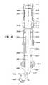
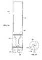
- FIG. 32illustrates a conventional system for directional drilling with casing using a BHA 3100 .
- the BHA 3100 with a pilot drill bit 3108is typically run through the casing 3104 (lining a wellbore 3102 ) and secured to a bottom portion of the casing 3104 with a casing latch 3106 .
- the BHA 3100may be operated in a rotary mode, by rotating the casing from the surface of the wellbore.
- the BHA 3100may include a downhole motor 3112 above the pilot bit 3108 .
- the motor 3112may be integral with a bent subassembly (or housing) 3114 to bias the pilot in the desired deviated direction (thus, the motor 3112 is commonly referred to as a “bent housing motor”).
- the deviated holeis drilled by adjusting the bent subassembly 3114 to point the pilot bit 3108 in the desired deviated direction.
- the trajectory of the deviated holeis typically dictated by the curvature that passes through the centers of the pilot bit 3108 , the bend in the motor 3112 , and the casing latch 3106 .
- the deviated wellboremust be larger than the outside diameter of the casing 3104 to allow the casing to advance as the wellbore is extended. This is typically accomplished by utilizing an underreamer 3110 to enlarge a pilot hole drilled with the pilot bit 3108 . In other words, as the motor 3112 is operated, the pilot bit 3108 is rotated forming the pilot hole, which is then enlarged by the underreamer 3110 following behind.
- expandable blades of the underreamer 3110may be placed in a retracted position. The blades may be expanded prior to drilling the deviated hole and again retracted to retrieve the BHA 3100 , through the casing 3104 , after drilling.
- the BHA 3100may also include sensing equipment 3109 , commonly referred to as a logging-while-drilling (LWD) or measuring-while-drilling (MWD), to take trajectory measurements (e.g., inclination and azimuth) and possibly formation measurements (e.g., resistivity, porosity, gamma, density, etc.) at several points along the wellbore which may be later used to approximate the wellbore path.
- LWD equipmentusually contains the wellbore surveying sensors
- LWD equipmentusually contains formation logging sensors.
- the typical BHA 3100when connected to the casing 3104 with the casing latch 3106 , extends about 90 to 100 feet below the lower end of the casing 3104 .
- the extension of the BHA 3100 below the casing 3104allows the pilot drill bit 3108 to form a rat hole (extended wellbore) below the lower end of the casing 3104 .
- the rat holehas a diameter larger than the outer diameter of the casing 3104 due to the underreamer 3110 .
- the pilot bit 3108is rotated to drill directionally the casing 3104 into a formation.
- the casing 3104is then released from engagement with the casing latch 3106 of the BHA 3100 , and the casing 3104 is lowered over the BHA 3100 to the bottom of the rat hole.
- the BHA 3100is eventually removed from the wellbore, and the casing 3104 is left in the wellbore.
- the rat hole formation step and the step of lowering the casing 3104 over the BHA 3100are required when using the current system of drilling with casing 3104 using a BHA 3100 because the bent housing 3114 must have a bend extending below the casing 3104 sufficient to introduce the desired trajectory into the deviated hole.
- the directional force for drilling the directional wellboreis supplied by the motor 3112 bend of the bent housing 3114 of the BHA 3100 , as the bent housing motor 3112 pushes directly on and against the side of the wellbore. Because the bent housing motor 3112 pushes against the side of the wellbore, a resultant force is caused on the opposite side, of the underreamer 3110 and pilot drill bit 3108 .
- the system illustrated in FIG. 32may allow for the drilling of a deviated wellbore without removing casing, the system suffers a number of disadvantages.
- one disadvantagearises due to a lack of proper support between the casing latch 3106 and the point of contact of the pilot bit 3108 .
- the typical length between the casing latch 3106 and the pilot bit 3108may be in the range of between 40 feet to 120 feet, the BHA 3100 may buckle and lean towards a lower end of the deviated hole as downward force (i.e., “weight on bit”) is applied from the surface.
- This leaningis difficult to control and can severely affect the intended curvature and trajectory of the deviated hole.
- excessive lateral and axial vibrations in the BHA 3100may reduce removal rate, reduce operating lifetime, and/or cause damage to the various components of the BHA 3110 , particularly when drilling in rotary mode.
- a further disadvantage of the system of FIG. 32lies in the large length of the rat hole drilled below the lower end of the casing 3104 , into which the casing 3104 must be lowered over the BHA 3100 . Lowering the casing 3104 over the BHA 3100 in the 90-100 foot rat hole adds an extra step to the directional drilling with casing operation. Additionally, the system places unnecessary directional force directly on the BHA 3100 . Still another disadvantage in conventional drilling with casing systems is that the MWD 3109 does not provide real time survey information and, thus, the trajectory of the deviated hole can only be verified after drilling.
- the bore directionWhen directionally drilling with a drill string, as the well is drilled, the bore direction must be checked or monitored, to ensure that the bore direction is not deviating from its intended direction.
- monitoringis typically provided by positioning a survey tool in a downhole location, in a rotationally fixed or known position, and monitoring signals therefrom to determine the orientation of the drill string in the earth. Where the drill string is pulled from the well after the wellbore is drilled, and the well is then cased, this is easily accomplished by fixing the survey tool in a subassembly in the drill string, and thus the survey tool is continuously in the borehole when the drill bit is at the bottom of the hole.
- Embodiments of the inventionprovide systems and methods for performing drilling, casing, and cementing operations which substantially reduce the time and costs for completing a well. More particularly, embodiments of the invention provide systems and methods for performing a drilling operation while casing the wellbore which allows a cement operation to be performed subsequently without having to first retrieve the motor system utilized for the drilling operation.
- embodiments of the present inventionprovide a method for directing a trajectory of a lined wellbore comprising providing a drilling assembly comprising a wellbore lining conduit and an earth removal member, directionally biasing the drilling assembly while operating the earth removal member and lowering the wellbore lining conduit into the earth, and leaving the wellbore lining conduit in a wellbore created by the biasing, operating and lowering.
- Embodiments of the inventionare capable of performing these operations in a variety of settings utilizing different equipment and tools and perform deviated drilling or nudging operations which produce deviated wells.
- embodiments of the inventionmay be utilized with an inter string, a bent pup joint, an orientation device, or without such tool.
- the apparatusmay be utilized to perform a casing expansion operation concurrently with the retrieval of the motor system utilized for the drilling operation.
- an apparatus for drillingcomprises a motor operating system disposed in a motor system housing, a shaft operatively connected to the motor operating system, the shaft having a passageway, and a divert assembly disposed to direct fluid flow selectively to the motor operating system and the passageway in the shaft.
- the divert assemblyfacilitates switching of fluid flow to the motor operating system during a drilling operation and fluid flow through the passageway in the motor system during a cementing operation such that the motor system need not be removed to perform a cementing operation for the well.
- Another embodimentprovides an apparatus for drilling with casing, comprising a casing, a motor system retrievably disposed in the casing, and a drill face operably connected to shaft of the motor system.
- the motor systemcomprises a motor operating system disposed in a motor system housing; a shaft operatively connected to the motor operating system, the shaft having a passageway; and a divert assembly disposed to direct fluid flow selectively to the motor operating system and the passageway in the shaft.
- a method for drilling and completing a wellcomprises pumping drilling fluid or drill mud to a motor system disposed in a casing; rotating an earth removal member, preferably a drill face, connected to the motor system; diverting fluid flow to a passageway through the motor system; and pumping cement through the passageway to the drill face.
- the motor systemmay be retrieved after the cement operation, and a casing expansion operation may be performed while retrieving the motor system.
- An additional aspect of the present inventioninvolves a method of initiating and continuing the formation of a wellbore by selectively altering the path of the casing string inserted into the formation as it travels downward into the formation.
- the diverting apparatuscomprises the casing string and cutting apparatus, along with a bend introduced into the casing string which influences the casing string to follow the general direction of the bend when forming a wellbore.
- the diverting apparatuscomprises the casing string and cutting apparatus, as well as a diverter in the form of an inclined wedge releasably attached to a lower end of the casing string.
- the diverting apparatuscomprises the casing string, the cutting apparatus, and a fluid deflector.
- the diverting apparatusin yet another embodiment comprises the casing string, the cutting apparatus, the fluid deflector, and pads placed on the outer diameter of the casing string.
- the diverting apparatusalso involves diverting fluid.
- the diverting apparatuscomprises the casing string, the cutting apparatus, and a second cutting apparatus disposed on the outer diameter of a portion of the casing string above the cutting apparatus.
- a further aspect of the present inventionis an apparatus and method for use with the diverting apparatus embodiments.
- the diverting apparatusis releasably connected to a drilling apparatus.
- the releasable connection between the drilling apparatus and the diverting apparatusis released.
- the drilling apparatusis then pulled upward to drill through the inner diameter of the casing string to remove any obstructions present inside the casing string which were previously used to divert the wellbore. Additional casing strings may then be hung off of the casing string, and further operations may then be conducted through the casing string.
- An even further aspect of the present inventioninvolves a method and apparatus for surveying the path of the wellbore while penetrating the formation with the casing string to form the wellbore.
- One embodimentprovides a drilling assembly for extending a wellbore, the drilling assembly adapted to be run through casing lining the wellbore.
- the drilling assemblygenerally includes a casing latch for securing the drilling assembly to the casing, a bit attached to a bottom portion of the drilling assembly, a biasing member for providing the bit with a desired deviation from a center line of the wellbore, and at least one adjustable stabilizer for supporting the drilling assembly between the casing latch and the bit.
- the drilling assemblyfor extending a wellbore, the drilling assembly attachable to casing lining the wellbore.
- the drilling assemblygenerally includes a bit disposed on a bottom portion of the drilling assembly, the bit adapted to be expanded from a first position for running through the casing to a second position for drilling a hole below the casing, the hole having a greater diameter than an outer diameter of the casing, and at least one stabilizer positioned between the bit and the bottom portion of the casing, the stabilizer adapted to be adjusted from a first position for running through a casing lining the wellbore to a second position for engaging an inner surface of the wellbore.
- Another embodimentprovides a method for drilling with casing.
- the methodgenerally includes lowering a drilling assembly down a wellbore through casing, the drilling assembly comprising an adjustable stabilizer and one or more drilling elements, adjusting one or more support members of the stabilizer to increase a diameter of the stabilizer, and operating the drilling assembly to extend a portion of the wellbore below the casing, the extended portion having a diameter greater than an outer diameter of the casing.
- the present inventiongenerally provides methods and apparatus for positioning a downhole tool, such as a survey tool, in a downhole location in a fixed position relative to the drill string, both with respect to the distance between the survey tool and the drill bit, as well as the rotational alignment or orientation of the tool to the drill string and drill bit structure, and the capability to retrieve such tool before the well is used for production.
- the drill stringis provided with a drillable float sub, which includes an orientation member therein into which a survey tool, such as an orientation tool, is received in a known orientation when the survey tool is positioned in a downhole location within such drill string, and which is also useable as a cement float shoe, for traditional cementing operation to cement the casing in place in the borehole.
- the survey toolis thereby orientable in the drill string to enable meaningful orientation survey of the drill bit and bore orientation, either on a sampling or continuous basis.
- the survey toolmay communicate information relating to orientation to the surface using via mud pulse telemetry, or other methods known to a person of ordinary skill in the art.
- the float subincludes a muleshoe profile which receives a mating muleshoe profile of the survey tool.
- the muleshoe profileis positioned in a sleeve, into which the survey tool may be positioned, such that the muleshoe profile on the survey tool will align on the muleshoe profile of the float sub, thereby orienting the survey tool in the drill string.
- the mule shoe profile of the float submay include a secondary alignment member, to enable the landing of survey tools therein which do not include such mule shoe profile.
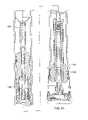
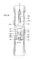
- FIG. 1is a schematic view of one embodiment of a system for drilling and completing a well in a formation under water.
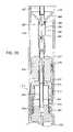
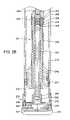
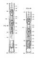
- FIGS. 2A and 2Bshow a cross-sectional view of one embodiment of a hollow shaft motor drilling system disposed in a casing.
- FIG. 3is a cross-sectional view of one embodiment of a hollow shaft motor drilling system illustrating a fluid divert operation.
- FIG. 4is a partial cross-sectional view of one embodiment of the divert system of FIG. 3 .
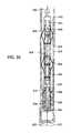
- FIG. 5is a cross-sectional view of one embodiment of a hollow shaft motor drilling system illustrating a cementing operation.
- FIG. 6is a cross-sectional view of one embodiment of a hollow shaft motor drilling system illustrating a system retrieval operation.
- FIG. 7illustrates one embodiment of the drill system which may be utilized for a drilling and casing operation in which casing may be added during the operation.
- FIG. 8is a cross-sectional view of one embodiment of a hollow shaft motor drilling system illustrating a drilling operation utilizing a bent pup joint.
- FIG. 9is a cross-sectional view of one embodiment of a hollow shaft motor drilling system illustrating a drilling operation utilizing a bent pup joint and an inter string.
- FIG. 10is a cross-sectional view of one embodiment of a hollow shaft motor drilling system illustrating a surveying operation.
- FIG. 11is a cross-sectional view of one embodiment of a hollow shaft motor drilling system disposed in an expandable casing.
- FIG. 12is a cross-sectional view of one embodiment of a hollow shaft motor drilling system disposed in an expandable casing illustrating an operation for expanding the casing after cementing.
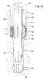
- FIG. 13is cross-sectional view of an embodiment of a diverting apparatus of the present invention disposed within a subterranean wellbore.
- a diverteris located below a casing with an earth removal member attached thereto.
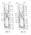
- FIG. 14is a cross-sectional view of an alternate embodiment of a diverting apparatus of the present invention disposed within a subterranean wellbore.
- a fluid deflectoris disposed within the earth removal member attached to the casing.
- FIG. 15is a cross-sectional view of an alternate embodiment of the diverting apparatus of FIG. 14 disposed within a subterranean wellbore. Stabilizer pads are disposed on the outer diameter of the casing.
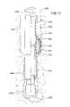
- FIG. 16is a cross-sectional view of a further alternate embodiment of a diverting apparatus of the present invention disposed within a subterranean wellbore.
- a cutting apparatus in the form of an elongated couplingextends outward from the outer diameter of the casing.
- the right side of the casing axis in FIG. 16is cut away to show a threadable connection.
- FIG. 17shows an alternate embodiment of the diverting apparatus of the present invention having an eccentric stabilizer disposed thereon.
- FIG. 18is a cross-sectional view of a drilling apparatus for use with the diverting apparatus of the present invention in the run-in configuration. The drilling apparatus is shown after drilling a wellbore into the formation.
- FIG. 19is a cross-sectional view of the drilling apparatus of FIG. 18 drilling through the diverting apparatus upon removal from the wellbore.
- FIG. 20is a cross-sectional view of the drilling apparatus of FIG. 18 upon removal of the drilling apparatus after drilling through the diverting apparatus.
- FIGS. 21 and 22illustrate a process for drilling through casing.
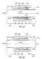
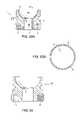
- FIGS. 23A and 23Bare perspective views of first and second ends of an embodiment of a drillable nozzle.
- FIGS. 24A and 24Bare perspective view of first and second ends of an alternative embodiment of a drillable nozzle.
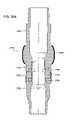
- FIG. 25is a section view of a first embodiment of a nozzle assembly disposed in a tool body.
- FIG. 26is a section view of a second embodiment of a nozzle assembly disposed in a tool body.
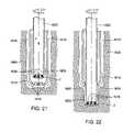
- FIG. 27is a section view of a third embodiment of a nozzle assembly disposed in a tool body.
- FIG. 28is a section view of a fourth embodiment of a nozzle assembly disposed in a tool body.
- FIG. 29is a section view of a tool body having nozzle assemblies disposed therein for drilling with casing.
- FIG. 30is a cross-sectional view of a lower end of an earth removal member having fluid passages therethrough.
- FIG. 31is a section view of a casing string capable of use in the present invention.
- FIG. 32illustrates an exemplary system for directional drilling according to the prior art.
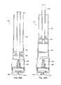
- FIGS. 33A-Dillustrate a system for directional drilling according to an embodiment of the present invention.
- FIG. 34is a flow diagram illustrating exemplary operations for directional drilling with casing according to an embodiment of the present invention.
- FIG. 35shows a sectional view of an alternate embodiment of a system for directional drilling with casing according to the present invention. An eccentric casing bias pad is shown on casing.
- FIG. 36shows a sectional view of a further alternate embodiment of a system for directional drilling with casing.
- FIG. 37is a cross-sectional view of another embodiment of a directional drilling assembly equipped with an articulating housing.
- FIGS. 38A-Bshow an exemplary articulating housing according to aspects of the present invention.
- FIG. 39shows another embodiment of a directional drilling assembly.
- FIG. 40shows the directional drilling assembly of FIG. 45 after the BHA has reached the bottom of the wellbore.
- FIG. 41shows the directional drilling assembly of FIG. 45 in operation.
- FIG. 42is a schematic view, in section, of a directional borehole being drilled.
- FIG. 43is a sectional view of a float sub in a downhole location indicated in FIG. 42 and a sectional view of a survey tool receivable therein.
- FIG. 43Ashows a side view of the survey tool of FIG. 43 .
- FIG. 44is a sectional view of the float sub of FIG. 43 , showing a survey tool in section, received and landed therein.
- FIG. 45is a sectional view of a float sub as in FIG. 44 , showing an alternative embodiment of a survey tool shown partially in section to be received therein.
- FIG. 46is a partial sectional view of the float sub of FIG. 45 , showing the survey tool in and landed on the float sub.
- FIG. 47shows a partial view of a float sub having a wellbore survey tool or sensor disposed therein.
- FIG. 48shows an embodiment of a survey tool assembly according to aspects of the present invention.
- FIG. 49shows the survey tool assembly of FIG. 48 in the survey mode.
- FIG. 50shows the survey tool assembly of FIG. 48 in the drilling mode.
- FIG. 51shows the bypass valve of the survey tool assembly of FIG. 48 in the closed position.
- FIG. 52shows the bypass valve of the survey tool assembly of FIG. 48 in the open position.
- FIG. 53Ais a sectional elevation of an earth boring bit nozzle.
- FIG. 53Bis a sectional view through the section y-y of FIG. 53A .
- FIG. 54shows an alternate embodiment of a bit nozzle made substantially of a non-metallic metal.
- FIG. 55shows a cross-sectional view of an alternate embodiment of a diverting apparatus disposed within a subterranean wellbore for use in directional drilling.
- FIG. 56Ais a cross-sectional view of a diverting apparatus used for expanding a casing.
- FIG. 56Bis a cross-sectional view of the diverting apparatus of FIG. 56A in the process of expanding the casing.
- FIG. 57is an upward sectional view of an earth removal member for use in the present invention.
- the casingmay be alternately jetted and rotated to form a wellbore.
- the rotation of the casing stringmay be accomplished either by rotating the entire casing or by rotating the cutting structure relative to the casing using a mud motor operatively attached to the casing.
- Embodiments of the present inventionprovide systems and methods for performing drilling with casing operations which substantially reduce the time and costs for completing a well. More particularly, some embodiments of the present invention provide systems and methods for performing a drilling operation while casing the wellbore which allows a cement operation to be performed subsequently without having to first retrieve the motor system utilized for the drilling operation.
- FIG. 1is a schematic view of one embodiment of a system 100 for drilling and completing a well in a formation 112 under water 108 .
- the system 100is shown in context of a deep sea drilling operation, embodiments of the invention may be utilized in drilling operations on land as well as under water 108 .
- the system 100includes a first, outer casing 185 , a second, inner casing 195 , and a drilling system 157 .
- the inner casing 195is releasably connected, preferably releasably latched, onto the outer casing 185
- the drilling system 157is releasably connected, preferably releasably latched, in the inner casing 195 .
- the drilling system 157includes an earth removal member, preferably in the form of a drill bit or drill shoe 167 which protrudes outside a terminal portion 147 of the outer casing 185 .
- An inter string or drill string 165connects the drilling system 157 to a ship or platform 155 at the surface of water 108 .
- the system 100may be utilized to drill and case a well in the formation 112 under the sea floor or mud line 160 .
- casing 185 or 195is made up of sections of casing. Each section of casing has a pin end and a box end for threadedly connecting to another section of casing above and/or below the casing section.
- a casing stringincludes more than one section of casing threadedly connected to one another.
- casingmay include a section of casing or a string of casing.
- FIGS. 2A and 2Bshow a cross-sectional view of one embodiment of a hollow shaft motor drilling system 200 disposed in a casing 219 .
- the hollow shaft motor drilling system 200illustrates one embodiment of the drilling system 157 , and the casing 219 is representative of the second casing 195 .
- the hollow shaft motor drilling system 200generally comprises a casing latch 211 , a hollow shaft motor 221 and a drill shoe 270 .
- the hollow shaft motor drilling system 200may include a guide assembly 203 attached to the casing latch 211 .
- the guide assembly 203includes a conical portion 204 and a tubular portion 206 .
- the conical portion 204guides mechanical devices run in from the surface or drilling fluid or drill mud into the tubular portion 206 .
- Such mechanical devicesmay include an inter string or drill string 207 , a closing ball, a latching dart 286 (see FIGS. 5 and 6 ), and other devices attached to a wireline.
- the tubular portion 206also provides a plurality of receptacle seats such as a spear seat 208 for receiving a stinger attached to an inter string 207 and a orientation tool landing seat 209 for receiving an orientation tool for performing a survey.
- the tubular portion 206is attached to the casing latch 211 and provides a fluid passageway which connects to a fluid passageway in the casing latch 211 .
- the casing latch 211is fixedly attached to the hollow shaft motor 221 and provides a mechanism for securing the hollow shaft motor drilling system 200 against an interior surface of the casing 219 .
- the casing latch 211includes a set of gripping members, preferably retractable slips 212 , disposed between an upper body 214 and a lower body 216 .
- the lower body 216includes one or more angled surfaces 218 which urge the slips 212 outwardly when the slips 212 are pushed against the angled surfaces 218 .
- a locking mechanismpreferably a locking ring 213 , is utilized to keep the slips 212 in the set position against the interior surface of the casing 219 once the slips 212 are extended.
- the locking ring 213may be spring loaded by a coil spring 222 and released from a locking position by breaking one or more release shear pins 224 .
- An upper cup seal assembly 226is disposed on an outer surface of the upper body 214 to provide a seal between the casing latch 211 and the casing 219 .
- the casing latch 211includes an axial tube 228 which provides a fluid passageway through the casing latch 211 to the hollow shaft motor 221 .
- One or more bypass ports 217may be disposed on the axial tube 228 and on the upper body 214 to facilitate fluid flow (e.g., drilling fluid or drill mud) during retrieval of the hollow shaft motor drilling system 200 .
- the lower body 216 of the casing latch 211is attached to the hollow shaft motor 221 .
- the hollow shaft motor 221provides the mechanism for rotating the drilling member 270 (e.g., a rotating drill face on a drill shoe).
- the hollow shaft motor 221includes a housing 242 , a motor operating system 244 , a shaft 246 , and a fluid divert assembly 248 .
- the housing 242includes an upper opening 249 which provides the connection to the casing latch 211 and continues the axial passageway 228 from the casing latch 211 .
- a lower cup seal 251may be disposed on an outer surface of the housing 242 to provide a seal against the interior surface of the casing 219 .
- the motor operating system 244is a hydraulic motor system which is operated by fluids (e.g., drilling fluid or drill mud) pumped through the motor operating system 244 .
- the motor operating system 244may be a stator system or a turbine system and turns the shaft 246 .
- the shaft 246is disposed axially along the hollow shaft motor 221 and includes an axial passageway 223 which is connected to the axial passageway 228 from the casing latch 211 .
- the fluid divert assembly 248is disposed at an upper portion of the axial passageway 223 to divert fluids into the motor operating system 244 or to direct fluid flow through the passageway 223 .
- the fluid divert system 248includes a closing sleeve 252 , one or more divert ports 254 , and a shear ring 256 .
- the shear ring 256keeps the closing sleeve 252 in the open position which allows the divert ports 254 to divert fluids into the motor operating system 244 .
- the shearing ring 256is broken by mechanical means, for example, by dropping a ball 261 (see FIG. 3 ) from the surface.
- the fluid divert system 248also includes a rupture disk 258 and an extrudable ball seat 260 for facilitating moving the closing sleeve 252 to a closed position which shuts off fluid delivery to the motor operating system 244 and diverts fluid flow through the axial passageway 223 in the shaft 246 .
- the extrudable ball seat 260includes a seat opening and may be made from a frangible material such as brass, aluminum, rubber, plastic, mild steel, and other material which may be opened, extruded or expanded when a predetermined pressure is applied to the seat opening.
- a frangible materialsuch as brass, aluminum, rubber, plastic, mild steel, and other material which may be opened, extruded or expanded when a predetermined pressure is applied to the seat opening.
- the rupture disk 258may be made from a flangeable material which, when ruptured or broken by a ball 261 , opens up in a clover leaf pattern generally and does not break off into pieces. When a rupture disk 258 has been broken, fluid flow is directed through the passageway 223 in the shaft 246 to the drill shoe 270 .
- the drill shoe 270is disposed at a terminal portion of the casing 219 .
- the drill shoe 270includes a mounting portion 272 for connecting to the end of the casing 219 .
- the mounting portion 272secures the drill shoe 270 to the casing 219 .
- the drill shoe 270includes a rotating drill face 274 which is rotatably disposed on the mounting portion 272 .
- a set of bearings 276is disposed between the mounting portion 272 and the rotating drill face 274 to facilitate rotational movement of the rotating drill face 274 .
- a ball joint(not shown) can be utilized instead of the bearings 276 .
- a spindle 278is attached to the rotating drill face 274 .
- the spindle 278is connected to a terminal portion of the shaft 246 of the hollow shaft motor 221 which provides the rotational movement to the rotating drill face 274 .
- the spindle 278includes a central passageway 229 which is connected to the axial passageway 223 in the shaft 246 of the hollow shaft motor 221 .
- the central passageway 229facilitates fluid flow (e.g., drill mud or cement) to one or more nozzles 227 (preferably bit nozzles) in the rotating drill face 274 .
- the nozzles 227allow fluid flow out of the drill face 274 and into the annulus between the casing 219 and the formation to facilitate drilling operations and cementing operations.
- a dart seat 282is positioned on the central passageway 229 for receiving a dart which may be utilized to seal the central passageway 229 .
- FIGS. 2A and 2Billustrate one embodiment of the drill system 200 which may be utilized for a drilling and casing operation in which the casing 219 is of a set length and the drill pipe (or inter string) 207 may be added from the surface during the operation.
- the hollow shaft motor drilling system 200may be utilized in offshore deep sea drilling in which the distance from the water surface to the sea floor is greater than the length of the casing 219 .
- the hollow shaft motor drilling system 200may be disposed on an inner casing 195 of a nested casing configuration, as shown in FIG. 1 .
- the inner casing 195may be latched to an outer casing 185 utilizing a J-slot mechanism (not shown).
- the outer casing 185is a 36-inch diameter casing
- the inner casing 195is a 22-inch diameter casing
- a drill shoe 270 or 135 having a 26-inch drill surface or drill bitis attached to the tip of the inner casing 195 .
- the nested casing configurationis attached to the surface platform 155 utilizing an inter string 165 and lowered down to the sea floor 160 .
- drilling fluid or drill mudis pumped from the surface through the inter string 207 attached to the hollow shaft motor drilling system 200 to provide the hydraulic power to drive the motor operating system 221 which rotates the drill shoe 270 .
- the outer casing 185(see FIG. 1 ) is jetted/drilled to a first target depth with the inner casing 195 , 219 latched inside.
- the outer casing 195 , 219may be directionally drilled into the formation using any of the embodiments shown in FIGS. 13-20 and described below. By nudging the outer casing 195 , 219 , the direction of the wellbore may be started so that subsequent casing may be drilled further into the wellbore at an angle.
- the inner casing 195 , 219is released from the outer casing 185 (e.g., by turning the inner casing 195 , 219 through the J-slot mechanism) and continued to be drilled/jetted down until a second target depth is reached.
- the methods and apparatus of FIGS. 13-20 described belowmay also be used on the outer casing 185 .
- a ball 261is dropped from the surface through the casing 195 , 219 and into the extrudable ball seat 260 to shut off fluid flow to the motor operating system 244 and divert the flow to the passageway 223 in the shaft 246 .
- the ball 261is then pressured from the surface to a first predetermined pressure to shear ring 256 , thus moving the sleeve 252 to a closed position. At a second predetermined pressure, ball 261 extrudes through the seat 260 , then impacts and breaks rupture disc 258 , as shown in FIG. 3 .
- FIG. 3is a cross-sectional view of one embodiment of a hollow shaft motor drilling system 200 illustrating a fluid divert operation.
- FIG. 4is a partial cross-sectional view of one embodiment of a divert system 248 in a closed position in which the ports 254 are closed off from delivering fluid flow to the motor operating system 244 .
- fluide.g., drilling fluid, drill mud, or cement
- the shear ring 256breaks and the sleeve 252 closes the port(s) 254 .
- the ball 261shoots through the extrudable ball seat 260 and breaks through the rupture disk 258 , allowing fluid flow through the passageway 223 .
- the ball 261travels through the passageway 223 and falls into a cavity 284 (shown in FIG. 2 ) in the spindle 278 .
- a cementing operationmay be performed.
- FIG. 5is a cross-sectional view of one embodiment of a hollow shaft motor drilling system 200 illustrating a cementing operation.
- a physically alterable bonding materialpreferably cement
- a latching dart 286is inserted from the surface to close off the central passageway 229 in the spindle 278 .
- the latching dart 286is utilized to prevent back flow through the central passageway 229 in the spindle 278 and to stop flow through the one or more bit nozzles 227 in the drill face 274 .
- a float valvemay be utilized to prevent back flow fluid pumped down through the drill shoe 270 .
- the latching dart 286is displaced down to the dart seat 282 by mud pumped in behind the dart 286 from the surface. Once the latching dart 286 is secured onto the dart seat 282 , a system retrieval operation may be performed to retrieve the motor system 221 and the casing latch 211 .
- FIG. 6is a cross-sectional view of one embodiment of a hollow shaft motor drilling system 200 illustrating a system retrieval operation.
- the slips 212 on the casing latch 211may be released by a mechanical jerking action (e.g., utilizing the inter string 207 or a wireline) which shears the releasing shear pin 224 .
- a mechanical jerking actione.g., utilizing the inter string 207 or a wireline
- the slips 212collapse inwardly and release from the interior surface of the casing 219 , and the motor system 221 and the casing latch 211 may be retrieved (e.g., physically picked up) from the surface by retracting or pulling up on the inter string 207 .
- the shaft 246 of the motor system 221is detached from the spindle 278 of the drill shoe 270 , leaving the latching dart 286 in the dart seat 282 .
- the bypass ports 217may be opened to allow remaining mud in the system to flow through the bypass ports 217 into the casing 219 .
- the motor system 221may be retrieved utilizing mechanical means other than the inter string (or drill pipe) 207 , such as, for example, cable wireline, coiled tubing, coiled sucker rod, etc.
- the hollow shaft motor drilling system 200facilitates drilling with casing and enables cementing the well in one single trip down without having to first retrieve the motor system 221 and the drill bit 270 .
- Considerable timeis reduced in drilling and casing a well, resulting in substantial economic saving.
- Embodiments of the hollow shaft motor drilling system 200may be utilized in a variety of applications.
- FIG. 7illustrates one embodiment of the drilling system 200 which may be utilized for a drilling and casing operation in which casing may be added during the operation.
- drilling fluid or drill mudis pumped from the surface through the inner diameter of the casing 219 to the hollow shaft motor drilling system 200 to provide the hydraulic power to drive the motor operating system 221 which rotates the drill shoe 270 .
- the casing 219is jetted/drilled to a target depth. The ability to drill a hole without rotating the casing 219 while adding casing at the surface may reduce the time needed to perform the drilling operations.
- the casing 219may be rotated by surface equipment (e.g., top drive, rotary table, etc.) during the jetting/drilling operation without or in addition to rotating the drill shoe 270 .
- surface equipmente.g., top drive, rotary table, etc.
- a fluid divert operation, a cementing operation, and a retrieval operationmay be performed, similar to the description above relating to FIGS. 3-6 , except fluids are pumped down from the surface through the interior diameter of the casing 219 instead of the inter string 207 .
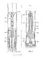
- FIG. 8is a cross-sectional view of one embodiment of a hollow shaft motor drilling system 800 illustrating a drilling operation utilizing a bent pup joint 802 .
- the motor system 221 and the drill shoe 270are latched onto a bent pup joint 802 .
- the bent pup joint 802is threaded onto casing with casing 219 being rotated at the surface during straight hole sections and being slid during directional sections to drill the casing 219 into the formation at an angle ⁇ .
- FIG. 9is a cross-sectional view of one embodiment of a hollow shaft motor drilling system 800 illustrating a drilling operation utilizing a bent pup joint 802 and an inter string 207 .
- This embodimentfacilitates addition of inter string 207 to a bent pup joint assembly 800 from the surface.
- the casing 219is of a set length while drill pipe (e.g., inter string) 207 is added at the surface.
- FIGS. 8 and 9shows a bent angle ⁇ (e.g., one degree bend) from the main drilling axis.
- Utilizing a bent pup joint 802allows for drilling a deviated hole or performing a nudging operation, without having to depend on a jetting/sliding operation.
- the casing 219is rotated when the casing 219 is not sliding or in a slide mode.
- the inter string 207may not be attached during the drilling operation, but may be utilized to retrieve the motor system 221 .
- an inter string 207it would be advantageous (e.g., faster) to perform the cementing operation utilizing the inter string 207 .
- Embodiments of the inventionmay be utilized to perform a survey operation to determine the direction of drilling.
- FIG. 10is a cross-sectional view of one embodiment of a hollow shaft motor drilling system 200 illustrating a surveying operation.
- a survey operationmay be performed by lowering an orientation device 1010 into the guide 204 .
- the inter string 207if utilized, is withdrawn to allow usage of the orientation device 1010 .
- the orientation device 1010is inserted into the landing seat 209 to determine the azimuth deviation of the drilled well.
- normal drilling operationsmay be resumed and corrections may be made to direct or deviate the well in the desired direction.
- the surveying operationmay also be conducted while drilling in a measuring-while-drilling operation, so that the angle of the casing may be continuously adjusted while drilling without interrupting the drilling and casing operation.
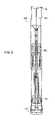
- FIG. 11is a cross-sectional view of one embodiment of a hollow shaft motor drilling system 1100 disposed in an expandable casing 1102 .
- the hollow shaft motor drilling system 1100includes similar components as the drilling system 200 described above except the housing 1142 of the hollow shaft motor drilling system 1100 is enlarged (as compare to housing 242 ) to conform with an enlarged terminal portion 1103 of the expandable casing 1102 .
- the casing latch 1110does not include bypass ports such as the bypass ports 217 on the casing latch 211 . Drilling and cementing operations as described above may be performed similarly utilizing the hollow shaft motor drilling system 1100 . After the drilling and cementing operations have been performed, the expandable casing 1102 may be expanded or enlarged from the inside utilizing the enlarged housing 1142 .
- FIG. 12is a cross-sectional view of one embodiment of a hollow shaft motor drilling system 1100 disposed in an expandable casing 1102 illustrating an operation for expanding the casing 1102 after cementing.
- the casing 1102may be expanded by mechanically pulling up the enlarged housing 1142 (e.g., utilizing an inter string such as 207 ) or by pumping fluids (e.g., mud) down to push the housing 1142 up, or by a combination of both of these methods.
- mudis pumped through the passageways 1128 and 1150 , filling the space inside the casing 1102 between the housing 1142 and the spindle 1178 of the drill shoe 1170 . With more mud being pumped down from the surface, pressure builds up between the housing 1142 and the spindle 1178 and pushes the housing 1142 upwards.
- the housing 1142pushes against the interior surface of the casing 1102 , expanding the casing 1102 as the housing 1142 travels upwardly toward the surface.
- the casing 1102is expanded to a larger internal diameter.
- expansion of the casing 1102squeezes the cement into remaining voids in the formation, resulting in a better seal or stronger cement job of the casing 1102 in the formation.
- additional casingmay be used to drill through the remaining tools and any cement in the cemented casing 202 , 802 , 1102 .
- the additional casingmay include the motor drilling system therein, as described in relation to FIGS. 1-12 . Additionally, the additional casing may be cemented into the formation and expanded by the motor drilling system.
- the motor drilling system 200 or 1100 described in relation to FIGS. 1-12may be used in conjunction with preferentially deflecting a casing in the form of a casing section or casing string in the wellbore in a direction using the casing, as shown and described in relation to FIGS. 13-20 .
- casing stringrefers to one or more sections of casing. More than one sections of casing are threadedly connected to one another.
- FIG. 13shows a diverting apparatus 10 of the present invention disposed in a wellbore 30 .
- the wellbore 30is a hole drilled in a subterranean formation 20 .
- the diverting apparatus 10comprises a cutting apparatus 50 connected to a lower end of a casing string 40 .
- the casing string 40is inserted into the formation 20 .
- the cutting apparatus 50has perforations 55 therethrough which allow fluid circulation between the wellbore 30 and the casing string 40 .
- the diverting apparatus 10also comprises a diverter 60 connected to the lower end of the casing string 40 below the cutting apparatus 50 .
- the diverter 60is connected to the lower end of the casing string 40 by a releasable attachment 65 .
- the releasable attachment 65is preferably a shearable connection.
- the diverter 60is preferably an inclined wedge attached to a portion of the casing string 40 by the releasable attachment 65 .
- the diverter 60has securing profiles 70 disposed at the lower end thereof, which are slots formed within the diverter 60 for grabbing the formation 20 .
- the securing profiles 70provide traction for the diverter 60 while the casing string 40 is penetrating the formation 20 , preventing rotational movement of the diverter 60 .
- the casing string 40 of the diverting apparatus 10may have a landing seat 45 disposed therein above the cutting apparatus 50 .
- the landing seat 45is a slot in which to fit a survey tool (not shown). Placing the survey tool into the landing seat 45 allows the angle at which the wellbore 30 is being drilled with respect to a surface 5 of the wellbore 30 to be ascertained and permits appropriate adjustment to the direction and/or angle of the wellbore 30 .
- the survey toolis first calibrated at the surface 5 . The survey tool is then run through the casing string 40 and into the landing seat 45 .
- the survey tool and landing seat 45permit continuous drilling with casing while surveying the conditions and direction of the wellbore 30 . Adjustment to the direction of the wellbore 30 can be made during the drilling operation.
- the survey toolis preferably a gyroscope, which is known to those skilled in the art.
- the diverting apparatus 10is drilled into the formation 20 by axial movement to form a wellbore 30 .
- pressurized fluidis introduced into the casing 40 concurrent with the axial movement of the casing 40 so that fluid flows downward through the inner diameter of the casing 40 , through the one or more nozzles 55 , into the wellbore 30 , and up through an annular space 90 between the outer diameter of the casing 40 and the inner diameter of the wellbore 30 to the surface 5 .
- a downward axial force calculated to release the releasable attachment 65is exerted on the casing 40 from the surface 5 .
- the releasable attachment 65releases so that the casing 40 with the cutting apparatus 50 attached thereto is moveable in relation to the diverter 60 .
- Other embodiments not shownmay allow the dropping of an object from the surface, such as a ball or dart, to release the diverting apparatus 10 from the casing 40 .
- Other embodiments not shownmay also include signals from the surface such as mud pulses to cause the release of the diverting apparatus 10 from the casing 40 .
- Still other embodiments not shownmay include the use of hydraulic pressure applied from the surface through the casing 40 or through a separate line such as an inter string to cause the release of the diverting apparatus 10 from the casing 40 .
- Downward force from the surface 5is applied to the casing 40 , urging the casing 40 along an upper side 61 of the diverter 60 , which remains at the same position within the wellbore 30 .
- the obstruction caused by the diverter 60forces the lower end of the casing 40 to deviate from its original axis at an angle essentially consistent with the slope of the upper side 61 of the diverter 60 , causing the casing 40 to move preferentially in a direction.
- the survey toolmay be placed within the landing seat 45 to determine the point at which the desired deviation angle has been reached.
- a setting operationis conducted, as setting fluid such as cement is introduced into the casing 40 from the surface 5 .
- the setting fluidflows downward into the casing 40 , through the one or more nozzles 55 , into the wellbore 30 and up into the annular space 90 .
- the setting fluidthen fills the annular space 90 to anchor the casing 40 within the wellbore 30 .
- the diverter 60remains permanently within the wellbore 30 .
- Additional casingmay then be drilled into the formation 20 below the casing 40 by rotational and/or axial force.
- the casing 40serves as a template for the angle followed by the additional casing strings, so that the additional casing strings are biased in the preferential direction. Because the additional casing strings are hung from the casing 40 , the additional casing strings divert in the desired direction at the angle in which the casing 40 was biased.
- a setting operation with setting fluidis conducted on additional casing strings as described above in relation to the casing 40 .
- FIG. 14shows an alternate embodiment of a diverting apparatus 110 of the present invention.
- the diverting apparatus 110is used to form a wellbore 130 in a formation 120 .
- the diverting apparatus 110comprises a casing string 140 wherein a bend is introduced into a portion of the casing string 140 to deflect the path of the wellbore 130 according to the bend in the casing string 140 .
- the casing string 140is used to penetrate the formation 120 .
- the bendis not co-axial relative to the axis of the casing string 140 .
- An arcis therefore integrated into the casing string 140 to urge the casing string 140 to form the diverted path for the wellbore 130 .
- FIG. 14illustrates introducing the bend into the casing string 140 by connecting component parts of the casing string 140 by male threads 135 which engage female threads 125 to form a threadable connection.
- the male and female threads 135 and 125are oriented on the casing string 140 so that the connection of the component parts disposes a lower portion 136 of the casing string 140 below the threadable connection at an angle off of the vertical axis, so that the lower portion 136 of the casing string 140 is at an angle with respect to an upper portion 137 of the casing string 140 .
- the female threadsare not cut co-axially into the lower portion 136 of the casing string 140 , so that the lower portion 136 of the casing string 140 is bent or slanted relative to the upper portion 137 of the casing string 140 .
- the lower portion 136 of the casing string 140is at an angle biased to the right of the upper portion 137 of the casing string 140 , which is essentially vertically disposed relative to a surface 105 of the wellbore 130 .
- the diverting apparatus 110further comprises a cutting apparatus 150 connected to a lower end of the casing string 140 .
- a cutting apparatus 150connected to a lower end of the casing string 140 .
- one or more fluid deflectors 175are formed through the casing string 140 and the cutting apparatus 150 .
- the fluid deflector 175is preferably one or more nozzles through the casing string 140 and cutting apparatus 150 which is angled outward with respect to the axis of the casing string 140 in the same direction in which the fluid deflector 175 is biased.
- the fluid deflector 175is biased and angled in the direction in which it is desired for the wellbore 130 to be diverted, which is the preferential direction of the wellbore 130 .
- a float sub 115is a tubular-shaped body which prevents fluid from flowing back up through the inner diameter of the casing string 140 after the setting fluid has been forced downward into the casing string 140 for the setting or cementing operation (described below). Also, the float sub 115 prevents fluid from flowing from the formation 120 in the casing string 140 to reduce frictional resistance while running the casing string 140 into the formation 120 .
- the float sub 115comprises a ball seat 102 with a ball 101 initially disposed therein, as shown in FIG. 14 .
- the ball seat 102may also be any type of one-way check valve, include a flapper-type valve.
- the diverting apparatus 110further includes a landing seat 145 for a survey tool (not shown), which operates in the same manner as described above with respect to the landing seat 45 of FIG. 13 .
- the float sub 115 and the landing seat 145are preferably made of drillable material such as aluminum or plastic, so that they may be drilled through after the casing string 140 is set within the wellbore 130 .
- FIG. 15is an alternate embodiment of the diverting apparatus 110 of FIG. 14 .
- the diverting apparatus 210 of FIG. 15which forms a wellbore 230 , comprises the same parts as those in FIG. 14 ; therefore, like parts are designated with the same last two numbers.
- the wellboresare 130 and 230
- the surfacesare 105 and 205
- the formationsare 120 and 220 , and so on.
- the diverting apparatus 210 of FIG. 15also comprises one or more pads 285 which are disposed on the outer diameter of the casing string 240 .
- the pads 285are located on the outer diameter of the casing string 240 on the side opposite the fluid deflector 275 .
- the pads 285which are spaced vertically along the casing string 240 , serve to reduce friction encountered in the formation 220 .
- the pads 285help to bias the casing string 240 outward at the desired angle in the preferred direction by keeping the casing string 240 from direct contact with the inner diameter of the wellbore 230 .
- the pads 285maintain the cutting structure 250 heading outward, preventing it from falling back to vertical with respect to the axis of the upper portion of the casing string 240 .
- the diverting apparatus 110 and 210 of FIGS. 14 and 15is similar, so they will be described in conjunction with one another.
- the diverting apparatus 110 , 210is drilled into the wellbore 130 , 230 axially by downward force applied from the surface 105 , 205 .
- the cutting apparatus 150 , 250drills into the formation 120 , 220 due to the axial force.
- pressurized fluidis introduced into the casing string 140 , 240 from the surface 105 , 205 to facilitate the downward movement of the diverting apparatus 110 , 210 into the formation 120 , 220 .
- the fluidforms a path for the diverting apparatus 110 , 210 in the formation and prevents mud and rock from the formation 120 , 220 from filling the inner diameter of the casing string 140 , 240 .
- the fluidflows through the casing string 140 , 240 , through the float sub 115 , 215 , through the fluid deflector 175 , 275 , and into an annular space 190 , 290 between the outer diameter of the casing string 140 , 240 and the inner diameter of the wellbore 130 , 230 .
- the fluidtends to flow into the area with the least obstruction.
- the fluid deflector 175 , 275urges the fluid outward into the formation 120 , 220 at the angle in the preferred direction with respect to the vertical axis of the casing string 140 , 240 , where no obstruction is present. In this way, fluid flow is selectively diverted out of a portion of the casing string 140 , 240 to form a deflected path for the wellbore 130 , 230 .
- the concentrated fluid flow into only one portion of the formation 120 , 220causes a profile 180 , 280 in a portion of the formation 120 , 220 to develop, forming a path through which the casing string 140 , 240 may travel with less frictional resistance than the alternative paths through the formation 120 , 220 .
- the lower portion 136 , 236 of the casing string 140 , 240is thus biased at an angle off of the vertical axis of the upper portion 137 , 237 casing string 140 , 240 , in the general direction and at the general angle of the fluid deflector 175 , 275 , so that the wellbore 130 , 230 is angled in the preferential direction and the path of the wellbore 130 , 230 is deflected accordingly.
- the fluidtends to flow outward at the angle off of the vertical axis at which the bend in the casing string 140 , 240 , in this case the bend produced by the male and female threads 125 , 225 and 135 , 235 , biased the diverting apparatus 110 , 210 .
- the lower portion 136 , 236 of the casing string 140 , 240is thus urged at an angle in the preferential direction with respect to the upper portion 137 , 237 of the casing string 140 , 240 due to the fluid deflector 175 , 275 and the threadable connections 125 , 225 and 135 , 235 .
- the pads 285further urge the diverting apparatus 210 in the desired direction by reducing friction of the casing string 240 against the formation 220 along the way downward, as well as by propping the lower end of the casing string 240 with the cutting apparatus 250 , thus preventing the cutting apparatus 250 from falling back into the vertical angle with respect to the axis of the casing string 140 , 240 .
- the path of the casing string 140 , 240 and, thus, of the wellbore 130 , 230is deflected in the desired direction to avoid intersection with other wellbores.
- pressurized setting fluidsuch as cement may optionally be introduced into the wellbore 130 , 230 from the surface 105 , 205 through the casing string 140 , 240 .
- the setting fluidflows through the casing string 140 , 240 , through the float sub 115 , 215 , through the fluid deflector 175 , 275 , and then outward into the annular space 190 , 290 .
- the float sub 115 , 215functions much like a check valve, in the open position allowing setting fluid to flow downward through the casing string 140 , 240 , and in the closed position preventing setting fluid from flowing back upward through the casing string 140 , 240 toward the surface 105 , 205 .
- the setting fluidwhen flowing into the casing string 140 , 240 from the surface 105 , 205 , forces the ball 101 , 201 downward within the float sub 115 , 215 and out of the ball seat 102 , 202 .
- the setting fluidcan thus flow around the ball 101 , 201 and through the float sub 115 , 215 to flow into the annular space 190 , 290 .
- the setting fluidsolidifies within the annular space 190 , 290 to secure the casing string 140 , 240 within the wellbore 130 , 230 .
- setting fluidis no longer introduced into the casing string 140 , 240 to force the ball 101 , 201 out of the ball seat 102 , 202 , the ball 101 , 201 is again seated in the ball seat 102 , 202 so that setting fluid cannot flow back upward within the casing string 140 , 240 toward the surface 105 , 205 .
- the float sub 115 , 215 and the landing seat 145 , 245may be drilled through by a cutting structure. Additional strings of casing (not shown) may then be hung off of the casing string 140 , 240 .
- the additional casing stringsare biased at an angle with respect to the vertical axis because the casing string 140 , 240 leads the additional casing strings in its general direction and angle.
- the additional casing stringsare set with setting fluid just as the casing string 140 , 240 was set.
- FIGS. 14 and 15show a bend introduced into the casing 140 , 240 at the threadable connection of male and female threads 125 , 225 and 135 , 235 .
- a bend in the casing 140 , 240could be integrally machined in the casing 140 , 240 . It is also contemplated that embodiments of the present invention may include merely bending the casing 140 , 240 . The bend in the casing 140 , 240 would provide directional force for directionally drilling with the casing 140 , 240 .
- FIG. 55shows a further alternate embodiment of a nudging operation of the present invention.
- no bendis introduced into the casing as is shown in FIGS. 14 and 15
- no eccentric pads 285are located on the outer diameter of the casing as shown in FIG. 15 .
- one or more fluid deflectors (nozzles) 475are located on one side of an earth removal member 350 operatively attached to a lower end of a casing 440 and are angled outward with respect to the vertical axis of the casing 440 , which may include a casing section or a casing string having a plurality of casing sections. As shown and described in relation to FIGS.
- a fluid deflector 475is formed through the casing 440 and the earth removal member 450 , which is preferably a cutting apparatus such as a drill bit.
- the earth removal member 450may be a bi-center bit, expandable bit, drillable cutting structure, or the like, depending upon the application.
- the fluid deflector 475is biased and angled in the direction in which it is desired to divert the wellbore, or in the preferential direction of the wellbore.
- the fluid deflector 475is substantially the same as the fluid deflectors 175 and 275 of FIGS. 14 and 15 , respectively. As in the embodiments shown in FIGS. 14 and 15 , any number of fluid deflectors 475 may be utilized in the present invention.
- a float sub 415 and landing seat 445 for a survey toolmay be located within the diverting apparatus 410 .
- the float sub 415is substantially the same as the float subs 115 , 215 shown and described with respect to FIGS. 14 and 15 , the above description of the float subs 115 , 215 of FIGS. 14 and 15 and their operation applies equally to the float sub 415 of FIG. 55 .
- the landing seats 45 , 145 , and 245 of FIGS. 13 , 14 , and 15respectively, are substantially the same as the landing seat 445 , the above description of the landing seats 45 , 145 , and 245 and their operation applies equally to the embodiment of FIG. 55 .
- the diverting apparatus 410includes a plurality of fluid deflectors or nozzles 475 grouped together on one side of the cutting apparatus 450 .
- FIG. 57illustrates a particularly preferred embodiment, which includes three fluid deflectors or nozzles 475 A, 475 B, and 475 C through the casing 440 and cutting apparatus 450 for preferentially directing the fluid flow into the formation.
- the fluid deflectors 475 A, B, and Cmay be pointed straight down, where the axes of the fluid deflector 475 A, B, and C are parallel to the axis of the cutting apparatus 450 .
- the fluid deflectors 475 A, B, and Cmay be angled radially outward from the cutting apparatus 450 , so that the axes of the fluid deflectors 475 A, B, and C are at an angle with respect to the axis of the cutting apparatus 450 .
- one or more of the fluid deflectors 475 A, B, and Cmay be angled, while the remainder of the fluid deflectors 475 A, B, and C may be straight.
- the vertical axes of the fluid deflectors 475 A, B, and Care angled approximately 30 degrees radially outward from the vertical axis of the cutting apparatus 450 .
- the diverting apparatus 410may be alternately jetted by flowing fluid through the casing 440 and into the fluid deflector 475 while simultaneously lowering the casing 440 into the formation, and rotated by rotating the entire casing 440 within the formation.
- fluid through the deflector 475forms a path for the diverting apparatus 410 in the formation in the same way as described above in relation to the fluid deflectors 175 , 275 shown and described in relation to FIGS. 14 and 15 .
- the fluidflows into the area of the formation having the least obstruction, and the angled orientation of the fluid deflector 475 urges the fluid outward from the casing 440 into the formation at the angle in the preferred direction with respect to the vertical axis of the casing 440 .
- Concentrated fluid flow in a portion of the formationcauses a profile in a corresponding portion of the formation to form so that the casing 440 travels through the path of least resistance to form a deflected wellbore path.
- a physically alterable bonding materialsuch as cement may be flowed through the casing 440 to set the casing 440 within the wellbore, in the same manner as described in relation to setting the casing 140 , 240 of FIGS. 14 and 15 , using the float sub 415 .
- the survey toolwhich may optionally be located within the landing seat 445
- the float sub 415 , landing seat 445 , and cutting apparatus 450may each be drilled through by a subsequent cutting structure, e.g., a cutting structure located on a subsequent drill string or subsequent casing.
- the additional casingmay then be hung off the casing 440 (preferably at a lower end of the casing 440 ) and possibly set with a physically alterable drilling material within the wellbore. This process may be repeated as desired to drill and case the wellbore to a total depth.
- the additional casing stringsare biased at an angle with respect to the vertical axis of the casing 440 because of the casing 440 deflection.
- the casing 440may be alternately jetted and/or rotated to form a wellbore within the formation.
- the rotation of the casing 440is halted, and a surveying operation is performed using the survey tool (not shown) to determine the location of the one or more fluid deflectors 475 within the wellbore.
- Stokingmay also be utilized to keep track of the location of the fluid deflector(s) 475 , the method of which is described in relation to FIG. 31 (see below).
- the casing 440is rotated if necessary to aim the fluid deflector(s) 475 in the desired direction in which to deflect the casing 440 . Fluid is then flowed through the casing 440 and the fluid deflector(s) 475 to form a profile (also termed a “cavity”) in the formation. Then, the casing 440 may continue to be jetted into the formation. When desired, the casing 440 is rotated, forcing the casing 440 to follow the cavity in the formation.
- the locating and aiming of the fluid deflector(s) 475 , flowing of fluid through the fluid deflector(s) 475 , and further jetting and/or rotating the casing 440 into the formationmay be repeated as desired to cause the casing 440 to deflect the wellbore in the desired direction within the formation.
- a further alternate embodiment of the present inventioninvolves accomplishing a nudging operation to directionally drill the casing 440 into the formation and expanding the casing 440 in a single run of the casing 440 into the formation, as shown in FIGS. 56A and 56B . Additionally, cementing of the casing 440 into the formation may optionally be performed in the same run of the casing 440 into the formation.
- FIGS. 56A-Bshow the diverting apparatus 410 , including casing 440 , the earth removal member or cutting apparatus 450 , the one or more fluid deflectors 475 (which may be a plurality of fluid deflectors arranged as shown and described in relation to FIG. 57 ), and the landing seat 445 of FIG. 55 .
- Additional components of the embodiment of FIGS. 56A and 56Binclude an expansion tool 442 capable of radially expanding the casing 440 , preferably an expansion cone 442 ; a latching dart 486 ; and a dart seat 482 .
- the expansion cone 442may have a larger outer diameter at its upper end than at its lower end, and preferably slopes radially outward from the upper end to the lower end.
- the expansion cone 442may be mechanically and/or hydraulically actuated.
- the latching dart 486 and dart seat 482are used in a cementing operation.
- the diverting apparatus 410is lowered into the wellbore with the expansion cone 442 located therein by alternately jetting and/or rotating the casing 440 , most preferably by nudging the casing 440 according to the preferred method described in relation to FIG. 55 .
- a running tool 425is introduced into the casing 440 .
- a physically alterable bonding materialpreferably cement
- cementis pumped through the running tool 425 , preferably an inner string.
- cementis flowed from the surface into the casing 440 , out the fluid deflector(s) 475 , and up through the annulus between the casing 440 and the wellbore.
- the dart 486is introduced into the inner string 425 .
- the dart 486lands and seals on the dart seat 482 .
- the dart 486stops flow from exiting past the dart seat, thus forming a fluid-tight seal.
- Pressure applied through the inner string 425may help urge the expansion cone 442 up to expand the casing 440 .
- mechanical pulling on the inner string 425helps urge the expansion cone 442 up.
- a float valve 415as shown and described in relation to FIG. 55 may be utilized to prevent back flow of cement.
- the latching dart 486is ultimately secured onto the dart seat 482 , preferably by a latching mechanism.
- the running tool 425may be any type of retrieval tool.
- the retrieval of the expansion cone 442involves threadedly engaging a longitudinal bore through the expansion cone 442 with a lower end of the running tool 425 .
- the running tool 425is then mechanically pulled up to the surface through the casing 440 , taking the attached expansion cone 442 with it.
- the expansion cone 442may be moved upward due to pumping fluid, down through the casing 440 to push the expansion cone 442 upward due to hydraulic pressure, or by a combination of mechanical and fluid actuation of the expansion cone 442 .
- the expansion cone 442moves upward relative to the casing 440 , the expansion cone 442 pushes against the interior surface of the casing 440 , thereby radially expanding the casing 440 as the expansion cone 442 travels upwardly toward the surface.
- the casing 440is expanded to a larger internal diameter along its length as the expansion cone 442 is retrieved to the surface.
- expansion of the casing 440is performed prior to the cement curing to set the casing 440 within the wellbore, so that expansion of the casing 440 squeezes the cement into remaining voids in the surrounding formation, possibly resulting in a better seal and stronger cementing of the casing 440 in the formation.
- expansion of the casing 440 by the expansion cone 442 in the method describedmay also be performed when the casing 440 is set within the wellbore in a manner other than by cement.
- the cutting apparatus 450may be drilled through by a subsequent cutting structure (possibly attached to a subsequent casing) or may be retrieved from the wellbore, depending on the type of cutting structure 450 utilized (e.g., expandable, drillable, or bi-center bit). Regardless of whether the cutting structure 450 is retrievable or drillable, the subsequent casing may be lowered through the casing 440 and drilled to a further depth within the formation. The subsequent casing may optionally be cemented within the wellbore. The process may be repeated with additional casing strings.
- FIG. 16shows a diverting apparatus 310 drilled into a formation 320 to form a wellbore 330 .
- the diverting apparatus 310includes an upper casing 340 , as well as a lower casing 341 .
- the upper and lower casings 340 and 341are inserted into the formation 320 as a unit.
- the lower casing 341has a first cutting apparatus 350 attached to its lower end.
- At least one nozzle 355runs through the lower end of the lower casing 341 as well as through the first cutting apparatus 350 .
- the at least one nozzle 355allows for fluid circulation between the casings 340 , 341 and the wellbore 330 .
- the diverting apparatus 310also includes an elongated coupling 391 , which is a collar used to connect the upper and lower casing strings 340 and 341 to one another.
- An upper portion of the elongated coupling 391is connected to a lower portion of the upper casing 340 by a threadable connection 342 .
- a lower portion of the elongated coupling 391is attached to an upper portion of the lower casing 341 by a threadable connection 343 .
- the elongated coupling 391has a second cutting apparatus 395 located on its outermost portion. In the alternative, only one casing (not shown) may have a second cutting apparatus 395 disposed thereon, which is not necessarily attached by a threadable connection.
- the outer diameter of the second cutting apparatus 395 /elongated coupling 391is larger than the outer diameter of the first cutting apparatus 350 .
- the second cutting apparatus 395extends along a substantial portion of the length of the elongated coupling 391 , and even along the lower portion of the elongated coupling 391 , so that the cutting apparatus 395 cuts into the formation 320 as the diverting apparatus 310 is forced progressively downward to form the wellbore 330 .
- the second cutting apparatus 395possesses hole-opening blades which increase the inner diameter of the upper portion of the wellbore 330 .
- the diverting apparatus 310is urged into the formation 320 by downward axial force applied from a surface 305 of the wellbore 330 .
- the elongated coupling 391 of the diverting apparatus 310allows the two casings 340 and 341 to be threaded together at the well site, so that the diverting apparatus 310 does not have to be pre-manufactured on the casing 340 or 341 .
- the second cutting apparatus 395may be pre-manufactured on the casing string (not shown).
- pressurized fluidis introduced into the diverting apparatus 310 through the inner diameter of the upper casing 340 as the casing 340 , 341 penetrates into the formation 320 to form the wellbore 330 , and then the fluid flows into the lower casing 341 , through the at least one nozzle 355 , up through a second annular space 389 between an inner diameter of the wellbore 330 and an outer diameter of the lower casing 341 , up through a first annular space 390 between the inner diameter of the wellbore 330 and an outer diameter of the upper casing 340 , and to the surface 305 of the wellbore 330 .
- the first cutting apparatus 350cuts into the formation 320 to form a lower portion of the wellbore 330 approximately equal to its diameter.
- the second cutting apparatus 395at the same time cuts into the formation 320 to form an upper portion of the wellbore 330 approximately equal to its diameter.
- the outer diameter of the upper portion of the wellbore 330is larger than the outer diameter of the lower portion of the wellbore 330 because of the difference in diameter between the first cutting apparatus 350 and the second cutting apparatus 395 .
- the first annular space 390 between the outer diameter of the upper casing 340 and the inner diameter of the upper portion of the wellbore 330is larger than the second annular space 389 between the outer diameter of the lower casing 341 and the inner diameter of the lower portion of the wellbore 330 .
- the axial movementis halted when the diverting apparatus 310 reaches its desired depth in the wellbore 330 .
- the first annular space 390 at the top of the wellbore 330is larger than the second annular space 389 at the bottom of the wellbore 330 as a result of the enlarged diameter second cutting apparatus 395 , so that a larger diametral clearance exists at the upper portion of the wellbore 330 than at the lower portion of the wellbore 330 .
- the larger diametral clearanceallows gravity to cause the casing to buckle in a direction.
- the direction in which gravity causes the casing to buckleis illustrated by the arrows disposed within the first annular space 390 .
- Fulcrum forceis illustrated by the arrows perpendicular to the axis of the casing 340 , 341 and adjacent to the second cutting structure 395 .
- a force in the opposite direction caused by formation 320 frictional resistanceis depicted by the arrow perpendicular to the axis of the first cutting apparatus 350 .
- the effect of the forces shown by the arrows in FIG. 16is that the upper casing 340 moves laterally through the first annular space 390 while staying essentially anchored at the lower portion of the lower casing 341 by the second annular space 389 , so that the diverting apparatus 310 angles in the preferred direction.
- the second cutting apparatus 395or the additional dressing on the outer diameter of the casing 340 and/or 341 , thus creates a larger cavity in the upper portion of the wellbore 330 than in the lower portion of the wellbore 330 , which facilitates lateral movement of the casing 340 in the preferred direction to create a deflected path for the wellbore 330 .
- a survey toolplaced in a landing seat (not shown) as described above may be used to determine whether the diverting apparatus 310 is bent in the desired direction at the desired angle.
- the first and second casings 340 and 341are cemented into place by a setting operation as described above. All of the components disposed within the inner diameter of the casing 340 are preferably made of drillable material so that they may be drilled through after the setting operation so that the inner diameter of the casing 340 is essentially hollow for subsequent wellbore operations.
- Subsequent casings(not shown) are then run into the wellbore 330 and hung from the existing lower casing 341 . The subsequent casings are biased in the desired direction at the desired angle because they essentially conform to the angle set by the original casings 340 and 341 .
- FIG. 17shows an alternative embodiment of a diverting apparatus of the present invention.
- the diverting apparatus 1310is substantially similar to the diverting apparatus 310 shown and described in relation to FIG. 16 ; as such, like parts will not be described again herein.
- the embodiment shown in FIG. 17is different from the embodiment shown in FIG. 16 because instead of the concentric stabilizer acting as the second cutting apparatus, an eccentric stabilizer 1395 disposed asymmetrically on one side of the outer diameter of the casing 1340 , 1341 adds additional directional force to the diverting apparatus 1310 .
- an eccentric stabilizer 1395disposed asymmetrically on one side of the outer diameter of the casing 1340 , 1341 adds additional directional force to the diverting apparatus 1310 .
- the stabilizer 1395which is preferably a 1-bladed actuable kick-pad, causes the upper portion of the casing 1340 to angle in the opposite direction from the eccentric stabilizer 1395 .
- a fluid deflector 1355or a perforation in the cutting apparatus 1350 angled in a direction with respect to vertical, may also be utilized to further deflect the path of the wellbore 1330 in a preferential direction at an angle with respect to the vertical axis of the casing.
- a two-step processmay be utilized.
- First, oriented jetting through the one or more fluid deflectors (bit nozzles) 1355may be accomplished to establish an initial inclination and direction of the casing.
- the casing 340 and 341 , 1340 and 1341may be rotary drilled further into the formation using the second cutting apparatus 395 , 1395 to build the angle.
- To rotary drillthe entire casing 340 and 341 , 1340 and 1341 is rotated while lowering the casing into the formation 320 , 1320 .
- the more efficient rotary drilling methodmay be utilized to build the angle of the wellbore 330 , 1330 .
- FIGS. 18-20illustrate an apparatus and method which may be utilized with a diverting apparatus 510 to drill through the inner diameter of the diverting apparatus 510 and remove obstructions so that additional casing strings (not shown) may be hung from the diverting apparatus 510 after the initial diversion.
- the apparatus and method of FIGS. 18-20may be used with any of the above embodiments to remove obstructing portions of the diverting apparatus residing within the inner diameter of the casing string after the casing string has been set within the wellbore.
- the diverting apparatus 510includes a casing string 540 with a second cutting apparatus 595 disposed on its outer diameter. The casing string 540 is inserted into a formation 520 to form a wellbore 530 .
- the inner diameter of the casing string 540has a drillable member 521 attached thereto which is connected to a drilling apparatus 522 through releasable connections 506 .
- the releasable connections 506which are preferably shearable connections, are used to fix the diverting apparatus 510 relative to the drilling apparatus 522 torsionally and axially.
- the drilling apparatus 522includes a drill string 523 with a first cutting apparatus 550 connected to its lower end.
- the first cutting apparatus 550is smaller in diameter than the second cutting apparatus 595 , so that the second cutting apparatus 595 possesses hole-opening blades which enlarge the inner diameter of the upper portion of the wellbore 530 .
- the first cutting apparatus 550has a cutting structure 551 attached to its lower end, at least one side parallel to a wellbore 530 , and its backside 526 at an angle from the wellbore 530 .
- the first cutting apparatus 550has at least one nozzle 555 which allows fluid to flow into and in from a formation 520 .
- Threads 501are preferably located on an upper end of the drill string 523 on its inner diameter.
- FIGS. 18-20The operation of the diverting apparatus 510 and the drilling apparatus 522 is shown in FIGS. 18-20 .
- FIG. 18illustrates the diverting/drilling apparatus 510 / 522 during run-in of the casing string 540 .
- the diverting apparatus 510 with the drilling apparatus 522 attached theretois pushed downward axially into the formation 520 to form the wellbore 530 .
- the diverting/drilling apparatus 510 / 522may also be rotated from a surface 505 of the wellbore 530 if desired to drill through the formation 520 .
- the first cutting apparatus 550drills into the formation 520 due to the pressure placed on the casing string 540 , which translates to the drilling apparatus 522 .
- the first cutting apparatus 550 on the drilling apparatus 522initially forms a portion of the wellbore 530 of a first diameter.
- the second cutting apparatus 595enlarges the diameter of the wellbore 530 in the portion of the wellbore 530 that it is forced into, as the second cutting apparatus 595 is larger in diameter than the first cutting apparatus 550 .
- a first annular space 590 between the outer diameter of the casing string 540 and the inner diameter of the wellbore 530is larger than a second annular space 589 between the outer diameter of the drill string 523 and the inner diameter of the wellbore 530 .
- the second cutting apparatus 595or the additional dressing on the outer diameter of the casing string 540 , thus creates a larger cavity in the upper portion of the wellbore 530 than in the lower portion of the wellbore 530 , which facilitates lateral movement of the casing string 540 in the preferred direction to create a deflected path for the wellbore 530 .
- Pressurized fluidis introduced into the casing string 540 while the casing string 540 penetrates into the formation 520 to form the wellbore 530 to flush mud and other substances out of the casing string 540 through the at least one nozzle 555 in the cutting apparatus 550 , outside the drill string 523 and the casing string 540 , and up to the surface 505 .
- a working string 503 or some other retrieving toolis lowered into the inner diameter of the casing string 540 (the working string 503 is shown in FIG. 19 ).
- the working string 503retrieves the drill string 523 using a pulling tool profile on its lower end, preferably male threads 502 on the working string 503 which threadedly engage female threads 501 of the drill string 523 .
- FIG. 19illustrates the next step in the operation of the diverting/drilling apparatus 510 / 522 .
- the working string 503is pulled upward axially from the surface 505 to release the releasable connection 506 .
- the releasable connection 506is preferably sheared off.
- the drill string 523is moveable axially and rotationally relative to the diverting apparatus 510 .
- the drilling apparatus 522is then pulled upward and rotated through the wellbore 530 by the working string 503 .
- the cutting structure 551 on the backside 526 of the first cutting apparatus 550contacts the lower end of the drillable member 521 and the portion of the releasable connection 506 remaining on the drillable member 521 .
- the cutting structure 551drills completely through the drillable member 521 and the remaining portion of the releasable connection 506 so that the drillable member 521 and releasable connection 506 are essentially destroyed.
- the inner diameter of the casing string 540is therefore left effectively unobstructed so that wellbore operations may be performed or additional casing strings (not shown) may eventually be hung from the casing string 540 .
- the drilling apparatus 522is then removed from the wellbore 530 by the working string 503 .
- the casing string 540is bent from the surface 505 to a side at an angle. Because of the larger first annular space 590 at the upper portion of the casing string 540 , the casing string 540 is fixed at its lower end but moves through the first annular space 590 at its upper portion so that the casing string 540 is biased at an angle. The additional casing strings may then be hung off of the casing string 540 at the angle at which the casing string 540 is biased, allowing the wellbore 530 to deviate in the desired direction at the desired angle.
- the float submay include, but is not limited to, the following: a check valve, poppet valve, flapper valve, or any other type of one-way valve.
- Drillable material utilized to form the float submay include, but is not limited to, one or more of the following: aluminum, plastic, metal, cement, or combinations thereof.
- the cutting structuremay be a drillable drill bit or an expandable bit latched into the casing.
- an expandable bit suitable for use in the present inventionrefer to U.S. Patent Application Publication No. 2003/111267 or U.S. Patent Application Publication No. 2003/183424, each which is incorporated by reference herein in its entirety.
- the diverting apparatus of the present invention and methods for their useallow effective diversion of a wellbore in a direction by deflecting a string of casing inserted into the wellbore.
- the apparatus and methodsare simple to build and permit the wellbore diversion to be accomplished while drilling with casing in a subterranean wellbore. Accordingly, the apparatus and methods of the present invention aid in preventing the unwanted intersection of valuable subterranean wellbores.
- the diverting apparatus of FIGS. 13-20 used for nudgingmay be utilized as the outer casing 185 shown in FIG. 1
- the inner casing 195may be any of the embodiments depicted in FIGS. 1-12 .
- the system 100is jetted and/or rotated to lower the outer casing 185 into the earth formation 112 at the desired depth to form a deviated wellbore.
- the releasable connection between the inner casing 195 and the outer casing 185is released, and the inner casing 195 is jetted and/or rotated, and the drilling system 157 may also be utilized to drill the inner casing 195 to the desired depth within the formation 112 while continuing to bias the direction and angle of the wellbore.
- the drilling systemmay include any of the embodiments shown in FIGS. 1-12 .
- the casingis alternately rotated and/or lowered or jetted into the formation.
- the rotation and jetting alternationaids in achieving the desired trajectory of the wellbore.
- hydraulic horsepoweris delivered to the cutting structure through one or more very restrictive orifices or nozzles (commonly termed “bit nozzles”) located in the cutting structure.
- the nozzlesare usually located in the body of the cutting structure proximate to the bottom of the wellbore.
- the function of the nozzlesis primarily to puncture the earth formation with “jet” impacts to facilitate formation of the wellbore, then to carry the cuttings up to the surface through the annulus between the wellbore and the casing. Additional functions of nozzles and the fluid flow therethrough include cleaning the cutting structure, cooling the bit cutters, and cleaning the bottom of the wellbore.
- the horsepower of the fluid flowing through the nozzlesmust be high during jetting.
- the nozzlesare subjected to extremely high erosion caused by pressure drop of the drilling fluid across the nozzles (e.g., from 500 to 3000 psi) and high velocity of the fluid through the nozzles (e.g., from 200 to 800 ft/s).
- a hard and tough materialsuch as tungsten carbide and/or ceramic is used to jet into the formation with a drill string in conventional drilling operations, as nozzles constructed from one or more of these materials may endure for thousands of hours without suffering fatal damage from erosion.
- Drilling with casing operationsmay require that the nozzles be drillable, and the current ceramic or tungsten carbide nozzles used for jetting in the drill string are not drillable.
- FIG. 21shows a process for drilling through a drillable cutting structure 1615 such as a drill bit or drill shoe operatively attached to a casing 1610 .
- the drillable cutting structure 1615has drillable nozzles 1616 therein.
- the casing 1610is lowered into the earth formation 1605 to form a wellbore 1630 by rotating the casing 1610 and/or by jetting the casing 1610 .
- the casing 1610may be set therein using a physically alterable bonding material such as cement (not shown).
- a casing 1620is lowered into the inner diameter of the casing 1610 while introducing fluid F through the inner diameter of the casing 1620 , out through nozzles 1626 in a cutting structure 1625 in the casing 1620 , and up to the surface.
- the cutting structure 1625may, but does not necessarily have to be, drillable.
- the cutting structure 1625may in the alternative be expandable and retrievable from the wellbore 1630 .
- FIG. 22illustrates the next step in an embodiment of the method for drilling through a cutting structure on a casing.
- the casing 1620is lowered and/or rotated through the casing 1610 to drill through at least a portion of the cutting structure 1615 .
- the nozzles 1616are preferably also drillable, as described below.
- FIG. 22shows the casing 1620 drilling to a further depth within the formation 1605 .
- the casing 1620may be expanded in one embodiment. If desired, the casing 1620 may also be set therein using the physically alterable bonding material.
- the cutting structure 1625may be left in the wellbore 1630 or may be drilled through by an additional casing (not shown) or by a drill string or other cutting device.
- the present inventionprovides drillable nozzles for use while drilling with casing.
- the base material and the nozzle(s) of the cutting structure 1615must be soft enough to allow subsequent casing 1620 to drill therethrough.
- a nozzle constructed of a sufficiently soft material used in a drilling with casing applicationmay only last a few hours under intense fluid erosion due to jetting. While enlarging the nozzle diameter to reduce velocity of the fluid through the nozzle aids in increasing nozzle longevity, this design remains problematic because the velocity of the fluid through the nozzle(s) may be so decreased that the casing no longer sufficiently drills through the formation during the jetting process.
- FIGS. 23A-23B , 24 A-B, and 25 - 29show embodiments of the present invention of a drillable nozzle, of which one or more may be used in any of the embodiments in FIGS. 1-22 .
- the nozzles shown in FIGS. 23A-23B , 24 A-B, and 25 - 29are insertable into the cutting structures of FIGS. 1-22 to provide a fluid path from the inner diameter of the casing into the wellbore.
- the drillable nozzlebreaks into portions, preferably fragments or “cuttings”, to be flowed to the surface using drilling fluid through the casing (not shown) which is used to drill through the drillable nozzle.
- the drillable nozzles of FIGS. 23A-23B , 24 A-B, and 25 - 29are drillable while remaining sufficiently devoid of erosive deconstruction to allow functional jetting through the nozzles with drilling fluid or any other fluid introduced into the nozzles.
- the drillable nozzle 1700is constructed of a hard, brittle, and wear-resistant material.
- Exemplary base materials which may be utilized to form the drillable nozzle 1700include, but are not limited to, tungsten carbide, ceramic, and polycrystalline diamond (PDC).
- FIG. 23Bshows a first end 1751 of the nozzle 1700 , through which fluid F is flowable during a drilling with casing operation.
- fluid Fis flowable through the casing, into the first end 1751 , through a bore 1761 disposed within the nozzle 1700 , out through a second end 1741 of the nozzle 1700 (shown in FIG. 23A ), then up through an annulus between the casing and the wellbore (or another casing disposed therearound) to the surface.
- the drillable nozzle 1700has one or more stressed portions therein, specifically shown as one or more stressed notches 1710 in FIGS. 23A-B .
- the stressed notches 1710are disposed within the outer diameter of the nozzle 1700 and are at least partially subflushed to the surface of the nozzle 1700 .
- the stressed notches 1710preferably extend the length of the nozzle 1700 coaxially with the bore 1761 of the nozzle 1700 ; however, it is contemplated that the stressed notches 1710 may extend only a portion of the length of the nozzle 1700 .
- the stressed notches 1710provide a stress point to cause the nozzle 1700 to break into portions or fragments when drilled through with a subsequent casing, drill string, or other cutting device.
- a preferred embodimentprovides that the notches 1710 are spaced substantially equidistant from one another along the outer diameter of the nozzle 1700 .
- the notches 1710are preferably relatively narrow cuts throughout the length of the nozzle 1700 .
- An o-ring groove 1705may exist within the outer diameter of the body of the nozzle 1700 around its circumference for disposing an o-ring (not shown) therein to seal the nozzle 1700 within a body of the tool in which the nozzle 1700 is disposed, such as a cutting tool (not shown).
- a filler material 1715preferably an extrudable material such as epoxy or vulcanized rubber, is disposed at least partially within the notches 1710 when the notches 1710 extend the length of the nozzle 1700 so that the o-ring may seal in the o-ring groove 1705 .
- the embodiment shown in FIGS. 24A and 24Bis substantially the same as the embodiment shown in FIGS. 23A and 23B , except for the following aspects.
- the stressed notches 1810extend only through a portion of the nozzle 1800 , coaxial with the bore 1861 .
- the notches 1810which are again at least partially subflushed to the surface of the nozzle 1800 , are interrupted along at least a portion of the outer diameter of the nozzle 1800 .
- the portion of the outer diameter of the nozzle 1800 over which the notches 1810 are interruptedis at least the at o-ring groove 1805 , negating the need to fill the notches 1810 with filler material 1715 as in FIGS. 23A-B .
- An additional difference between the nozzle 1700 and the nozzle 1800is that the notches 1810 are preferably substantially wider than the notches 1710 .
- the nozzles 1700 and 1800provide longevity to and allow high flow rates of fluid to pass through the cutting structure operatively connected to the casing. At the same time, when the nozzles 1700 and 1800 are drilled through by a subsequent cutting structure placed on a subsequent casing or drill string, the broken nozzle portions may be circulated to the surface through an annulus between the subsequent casing or drill string and the wellbore.
- FIGS. 25-28show nozzle assemblies which may be utilized in a drillable cutting structure operatively attached to casing.
- FIGS. 25 and 26show extended flow tubes 1910 , 2010 having a minimum thickness and a substantially uniform inner diameter or bore along each of their lengths.
- the flow tubes 1910 , 2010each represent a portion of the nozzle assemblies 1900 , 2000 .
- FIGS. 27 and 28show relatively thin profiled flow tubes 2180 , 2280 , each of which represent a portion of the nozzle assemblies 2100 , 2200 .
- the nozzle assembly 1900includes a flow tube 1910 disposed within a nozzle retainer 1920 .
- the flow tube 1910is substantially tubular-shaped with a longitudinal bore therethrough.
- the flow tube 1910which is preferably constructed of a relatively hard material such as ceramic, tungsten carbide, or PDC, is relatively thin (i.e., has a low thickness, as measured from an outer diameter to an inner diameter of the flow tube 1910 ) to facilitate drillability of the flow tube 1910 when a cutting structure, such as an earth removal member attached to a casing or a drill string, is drilled through the flow tube 1910 .
- the flow tube 1910has a substantially uniform inner diameter bore along its length to form a substantially straight bore through the flow tube 1910 .
- the substantially straight bore of the flow tube 1910maintains a minimal thickness along the length of the flow tube 1910 , thus enhancing drillability of the flow tube 1910 with a subsequent cutting structure, as any profile of the flow tube 1910 other than a straight bore therethrough would require an increase in material thickness perpendicular to the axis of the flow tube 1910 .
- the material thickness perpendicular to the axis of the flow tube 1910is presented to the subsequent cutting structure for drilling therethrough.
- the internal profile of the flow tube 1910 formed by the substantially straight bore therethroughpotentially decreases erosion of one or more portions of the nozzle 1900 because the fluid does not have to change direction due to obstructions within the bore when flowing through the nozzle 1900 .
- the nozzle retainer 1920which is preferably constructed of a relatively soft, drillable material such as copper or plastic, retains the flow tube 1910 therein.
- the flow tube 1910is preferably mounted within the nozzle retainer 1920 , which is a tubular-shaped body with a longitudinal bore therethrough.
- the nozzle retainer 1920may include an installation and removal feature, such as slots 1940 shown in FIG. 25 in an exit side face 1970 of the nozzle retainer 1920 .
- the slots 1940facilitate installation and removal of the nozzle assembly 1900 from a tool body 1925 .
- An integral feature of the nozzle assembly 1900is the extended length of the flow tube 1910 . Due to the extended length of the flow tube 1910 , the flow tube 1910 may be positioned as desired within the nozzle retainer 1920 by moving the flow tube 1910 up or down (right or left as shown in FIG. 25 ) within the nozzle retainer 1920 . Moving the flow tube 1910 up or down coaxial with the retainer 1920 allows entry and exit points of the fluid (shown in FIG. 25 , as the fluid flow moves left to right in the depicted assembly 1900 ) to be positioned as required either closer to or away from areas which may be susceptible to fluid erosion as a result of high velocity of the fluid and turbulence caused by the high flow rate of the fluid while the fluid is entering or exiting the flow tube 1910 .
- Exit standoff 1960is the distance of fluid flow through the flow tube 1910 measured from between the exit side face of the tool body 1925 and the exit point of the fluid from the flow tube 1910
- entry standoff 1950is the distance of fluid flow within the flow tube 1910 measured from between the entry side face of the tool body 1925 and the entry point of the fluid into the flow tube 1910 .
- the nozzle retainer 1920is preferably constructed of a relatively soft, drillable material such as copper or plastic.
- the material that the retainer 1920 is made fromis softer than the material of the flow tube 1910 .
- the material of the flow tube 1910is more resistant to corrosion than the material of the retainer 1920 .
- the internal bore of the retainer 1920is profiled to produce a controlled fit over the outer diameter of the flow tube 1910 , with a gap 1947 left between the flow tube 1910 and the retainer 1920 which is preferably substantially filled with a suitable adhesive 1945 for retaining the flow tube 1910 in the desired position within the retainer 1920 .
- the retainer 1920is seated within a nozzle profile 1965 in a tool body 1925 .
- the toolis preferably an earth removal member for cutting into an earth formation, and even more preferably a cutting structure such as a drill bit or drill shoe.
- the tool body 1925is preferably constructed of a relatively soft, drillable material such as copper or plastic.
- An outer surface of the retainer 1920has a seal groove 1907 having a seal 1905 therein for preventing fluid flow across the interface of the outer surface of the retainer 1920 and the nozzle profile 1965 of the tool body 1925 .
- An external thread 1915secures the nozzle assembly 1900 within the tool body 1925 .
- FIG. 25allows adjustability of the entry and exit points away from the tool body 1925 , creating a dead area 1930 in the fluid flow where high velocities and turbulence do not exist and directing fluid away from the retainer 1920 and tool body 1925 made of the soft, drillable material which is more susceptible to erosion due to fluid flow than the harder material of the flow tube 1910 .
- FIG. 26An alternate embodiment of a nozzle assembly 2000 of the present invention is shown in FIG. 26 .
- the nozzle assembly 2000is substantially similar to the nozzle assembly 1900 shown and described in relation to FIG. 25 ; therefore, like parts are labeled with like numbers (the last two digits of the numbers are the same).
- the difference between the assembly 2000 and the assembly 1900is that the entire nozzle assembly 2000 , including the nozzle retainer 2020 and the flow tube 2010 , may be constructed of a soft, drillable material such as copper or plastic or of a non-drillable material (such as when used in a retrievable cutting structure rather than a drillable cutting structure, as described below).
- This designallows for ease of construction of the nozzle assembly 2000 because the nozzle assembly 2000 can be made in one piece.
- No adhesive 1945is required in the embodiment of FIG. 26 because the nozzle assembly 2000 is one piece.
- the embodiment shown in FIG. 26may be utilized in drilling applications when the flow regime is such that easily drillable materials such as copper or plastic may be used while still gaining the benefits of the removal of localized turbulence from the tool body 2025 itself due to the straight-bore flow tube 2010 .
- This designallows for sleeving of the inner diameter of the flow tube 2010 by platting, shrink fitting, or any other suitable method to apply a wear-resistant material such as tungsten carbide and/or ceramic, where the thickness of the wear-resistant material is not so great as to detract from the process of drilling through the nozzle.
- the wear-resistant materialsmay be layered to obtain increased wear resistance and flexibility.
- the nozzle assemblies 1900 , 2000 shown in FIGS. 25-26allow for adjustment of the entry and exit standoff 1950 and 2050 , 1960 and 2060 by moving the flow tube 1910 , 2010 within the tool body 1925 , 2025 .
- the flow tube 1910 , 2010may be moved towards the entry or exit point of the fluid from the flow tube 1910 , 2010 as desired.
- FIGS. 27 and 28show further alternate embodiments of a nozzle assembly 2100 , 2200 .
- the embodiment shown in FIG. 27includes the nozzle assembly 2100 , which includes a nozzle retainer 2120 and a flow tube 2180 .
- the flow tube 2180is a profiled sleeve through which fluid flows from a tool such as a cutting structure attached to casing into the formation while jetting and/or drilling.
- the fluidenters into the flow tube 2180 from the left at an entry point and exits from the flow tube 2180 at an exit point.
- An inner diameter of the flow tube 2180 at the entry point of the fluidis larger than an inner diameter of the flow tube 2180 at the exit point of the fluid into the formation.
- the flow tube 2180is of a first inner diameter.
- the flow tube 2180then converges at an angle over a distance B to a second inner diameter, which is smaller than the first inner diameter.
- the second inner diameteris maintained over a distance C along the flow tube 2180 until the exit point of the flow tube 2180 .
- the flow tube 2180is constructed from a relatively hard material such as ceramic, tungsten carbide, or PDC to limit erosion of the flow tube 2180 , as described in relation to FIGS. 23A-B , 24 A-B, and 25 - 26 above.
- the flow tube 2180is relatively thin, as measured from the inner diameter of the flow tube 2180 to the outer diameter of the flow tube 2180 , to facilitate drilling through the relatively hard material of the flow tube 2180 by the subsequent cutting structure, as described above in relation to FIGS. 25-26 .
- a relatively soft, drillable material such as copper or plasticis utilized to form the nozzle retainer 2120 .
- the material making up the flow tube 2180is harder than the material of the retainer 2120 and tool body 2125 , and the material of the flow tube 2180 is more resistant to corrosion than the material of the retainer 2120 .
- the drillability of the soft materialallows the nozzle retainer 2120 to be of a larger thickness at the portion adjacent to the smaller diameter portion of the flow tube 2180 than its thickness at the other portions of the flow tube 2180 .
- the retainer 2120 inner diameterthus essentially conforms to the outer diameter of the flow tube 2180 .
- the nozzle assembly 2100is disposed in a tool body 2125 , which is preferably an earth removal member such as a drill shoe or a drill bit.
- the tool body 2125is preferably constructed of a relatively soft (at least compared to the flow tube 2180 ), drillable material such as copper, aluminum, cast iron, plastic, or combinations thereof.
- the material of the tool body 2185may or may not be the same as the material of the retainer 2120 .
- a seal 2105is disposed within a seal groove 2107 formed in an outer diameter of the retainer 2120 to prevent fluid from traveling in the area between the inner diameter of the tool body 2125 and the outer diameter of the retainer 2120 .
- Retaining threads 2115are located between the tool body 2125 and the retainer 2120 for connecting the nozzle assembly 2100 to the tool body 2125 .
- the nozzle assembly 2100is characterized by an extended exit.
- the extended exitis represented by an exit standoff 2160 , which is the length of the flow tube 2180 which extends past the end of the tool body 2125 from which fluid flows upon exit from the flow tube 2180 .
- the exit standoff 2160diverts the flow turbulence into an area away from the nozzle retainer 2120 and the tool body 2125 .
- FIG. 28shows an additional embodiment of the present invention.
- the embodiment shown in FIG. 28is substantially the same as the embodiment shown in FIG. 27 ; therefore, substantially similar elements to FIG. 27 which are in the “21” series are labeled in FIG. 28 with the “22” series.
- the difference between the embodiment of FIG. 27 and the embodiment of FIG. 28is that the embodiment shown in FIG. 28 not only includes the extended exit in the form of the exit standoff 2260 , but also includes the extended entry in the form of the entry standoff 2250 .
- the entry standoff 2250is the length of the flow tube 2280 which extends past the end of the tool body 2225 into which fluid flows upon entry into the flow tube 2280 .
- FIGS. 27 and 28may all be utilized in non-drillable applications such as in expandable cutting structures when drilling with casing.
- FIG. 29Shown in FIG. 29 is an embodiment of an earth removal member 1925 (“tool body”), preferably a cutting structure in the form of a drill shoe or drill bit, which includes two nozzle assemblies 1900 therein.
- the nozzle assemblies 1900are shown, but one or more of the nozzle assemblies 2000 , 2100 , 2200 may alternately be disposed within the tool body 2125 .
- the upper nozzle assembly 1900 shown in FIG. 29is oriented at an angle with respect to the vertical axis of the casing connected to the tool, thus illustrating the use of the nozzle assembly 1900 , 2000 , 2100 , 2200 to directionally drill by jetting through a fluid diverter, or an oriented nozzle or jet, as shown and described in relation to FIGS. 14-15 and 17 .
- FIG. 29also demonstrates by the lower nozzle assembly 1900 shown in the figure that the nozzle assembly 1900 , 2000 , 2100 , 2200 may also be utilized in casing drilling operations which do not involve nudging and directionally drilling.
- FIGS. 25-29may also be utilized in a retrievable cutting structure when a retrievable cutting structure is used with the embodiments of the invention shown in FIGS. 1-22 , such as an expandable bit.
- the embodiment of FIG. 26is especially applicable to non-drillable nozzles, where protection of the tool body 2025 at the entry and exit points is required, or when it is required to position the nozzle exit point closer to the formation.
- FIG. 30is a cross-sectional view of the lower end of a cutting structure having nozzles therethrough.
- nozzles of the cutting structuremay be blocked to prevent fluid flow therethrough.
- the unobstructed nozzleswill produce selective fluid flow from only a portion of the cutting structure, so that fluid flow is asymmetrically introduced into the wellbore and forms a diverted path for the casing within the formation.
- FIGS. 53A , 53 B, and 54provide drill bit nozzles that are constructed to withstand the abrasive and erosive impact of jetted drilling fluid, while also being suitable for subsequent drilling operations intended to drill through drill bit bodies to which the nozzles are attached, and indeed the nozzles themselves.
- the embodiments of FIGS. 53A-B and 54further provide a method of drilling a wellbore, wherein the drilling method is that commonly known as drilling with casing and wherein subsequent drilling may be undertaken by a subsequent drill bit, without the requirement of the removal of the earlier or first drill bit from the well bore, and wherein the earlier or first drill bit includes nozzles.
- FIGS. 53A-B and 5show embodiments of a new and improved drill bit nozzle comprising a body defining a through-bore, wherein the through-bore defines a passage for drilling fluid in use, wherein the surface of the through-bore within the body has a relatively high resistance to erosion and wherein the nozzle is characterized in that the body is made substantially of a material or materials that allow for the nozzle to be subsequently drilled through by standard wellbore drilling equipment.
- the through borehas an enlarged concave portion at an inlet side of the nozzle, communicating with a smaller diameter cylindrical portion.
- the nozzle bodymay be made of two materials, wherein the surface of the through-bore is made of a first material, wherein said first material is of relatively thin construction and has a high resistance to erosion, and wherein the remainder of the nozzle body is made of a second material that is easily drillable.
- the first or surface materialmay be a hard chrome.
- tungsten carbide or suitable alloysmay be used, their suitability being assessed by their ability to withstand erosive forces from the well fluid jetted through the through-bore.
- the second material forming substantially the majority of the nozzle bodymay be made typically of a softer metal, such as nickel, aluminum, copper or alloys of these.
- the second materialmay be copper and the surface or first material is hard chrome, wherein the hard chrome is applied to the copper body by electro-plating.
- a nozzle in accordance with the present inventionmay be made of a rubber material.
- rubberis typically not a “hard” material, it does nevertheless have a high resistance to erosion.
- rubber materialsmay be easily drilled by subsequent drilling bits.
- a nozzle in accordance with inventionmay be made of one or more materials and need not be made entirely or even partially of a metal material. Polyurethane or other elastomers may also be used.
- FIGS. 53A and 53Bthere is shown a drill bit nozzle 1 .
- the drill bit nozzle 1is adapted to be threadably engaged with a drill bit body (not shown) by virtue of the threaded portions 2 .
- the nozzle 1is provided with an annular body 3 that defines a through-passage or through-bore 4 .
- the through-bore 4is formed with an inlet having a concave enlarged portion 4 a which communicates with a cylindrical smaller diameter portion 4 b leading to an outlet 7 .
- the geometry of the through-bore 4is such that well fluid is jetted at high velocity out the outlet 7 .
- the nozzle through-bore 4is intended to receive drilling fluid at high velocities and with high pressure differentials.
- the surface 5 of the through-bore 4is constructed of a material that is suitable for withstanding the abrasive and eroding nature of the drilling fluid in use. Not only must the surface of the through-passage withstand the eroding forces of the drilling fluid, but in view of the proximity of the nozzles to the cutting surface of the drill bit, excessive wear may be induced in the event of a nonresistant material being employed as a result of the impact of small rock particles and other debris cut by the drill bit from the well formation. The erosive effect of rock particles within drill bit nozzles is well known and documented.
- the surface of the through-bore 4is preferably made from a hard material which, in an example embodiment of FIGS. 53A-B , is a hard chrome material. In another example, tungsten carbide may be used as the surface material.
- the surface materialwill typically be chosen as one which is able to be combined with a softer, drillable material whereby this softer, drillable material may form substantially the body of the drill bit nozzle, with the exception of the surface herein before mentioned.
- the second material from which substantially all of the nozzle body is madeis copper. Copper is selected as one suitable material as the surface coating of hard chrome may be easily applied to the copper body by electro-plating means. Additionally, copper is sufficiently soft to allow a subsequent drill bit to drill through the body of the nozzle.
- an alternative nozzle 12is made substantially of a single non-metallic material, preferably rubber. However, to enable the rubber nozzle 12 to be attached to a drill bit body, the nozzle 12 is provided with a threaded insert made of a metallic material. The threaded insert 11 is, nevertheless, made of a material which is sufficiently soft to allow a subsequent drill bit to drill through it.
- An advantage of the present inventionwill be apparent from the method of use of the drill bit nozzle as shown in FIGS. 53A-B and 54 and described above which allows for a drill bit bearing drill bit nozzles to be left in a wellbore during the cementing of casing and subsequently drilled through by standard wellbore drilling equipment to allow for the well to be extended.
- the inventionmay be seen to overcome the difficulty of providing drill bit nozzles in a manner that allowed for their resistance to wear from the erosive characteristics of jetted drilling fluid, while nevertheless enabling subsequent conventional or standard wellbore drilling equipment to drill through them.
- a casing stringmade up of a plurality of casing sections.
- Making up the casing stringinvolves rotating one casing section relative to another casing section to threadedly connect the casing sections together.
- Many of the directional drilling tools described in the figures of the present applicationinclude biasing tools (e.g., eccentric stabilizer and/or directional jet) disposed on the casing or within the casing, the location of which must be tracked from the surface of the wellbore to allow the operator to maintain the direction and angle of the deviated wellbore while drilling with the casing.
- biasing toolse.g., eccentric stabilizer and/or directional jet
- One method of tracking the position of the biasing tool on the casinginvolves marking the position of the biasing tool when the casing having the biasing tool thereon is first lowered into the formation (“stoking or scribing in the hole”). Marking the position may be accomplished by drawing a vertical chalk line along the casing as one casing section is threaded onto another. Then, when the made-up casing string is lowered into the wellbore, the portion of the marked casing section which remains located above the wellbore (e.g., by a spider on a rig floor) becomes the reference point for marking a chalk like after the next section of casing is threaded onto the casing string.
- a casing string 2300which may be utilized in the present invention while jetting into the formation includes a casing section 2320 having male threads 2321 threaded to a casing section 2330 having male threads 2331 by a collar 2315 having female threads 2311 and 2312 . Disposed within the collar 2315 is a buttress torque ring 2310 .
- the buttress torque ring 2310is a spacer placed in between the ends of the pins 2331 , 2321 of the casing sections 2330 , 2320 to provide a stop mechanism to stop torquing of the casing sections 2330 , 2320 at a given point.
- the buttress torque ring 2310may be used to hold the chalk line when scribing in the hole so that the chalk mark does not lose accuracy as to the location of the biasing tool because the rotational position of the casing sections 2330 , 2320 relative to one another changes.
- Additional embodiments of the present inventiongenerally provide improved methods and assemblies for drilling with casing (DWC).
- drilling assemblies according to the present inventionare supported between an attachment point at a bottom of the casing and the point of drilling contact by one or more adjustable stabilizers.
- the stabilizersmay have one or more adjustable support members that may be placed in a first (run-in) position giving the stabilizer a sufficiently small outer diameter to be run in through the casing with the drilling assembly.
- the support membersmay then be placed in a second position giving the stabilizer a sufficiently large outer diameter to engage an inner wall of the wellbore to provide support for the drilling assembly during drilling.
- Additional embodiments of the present inventionprovide directional force for directionally drilling the assembly on the casing rather than the BHA. Moreover, embodiments of the present invention reduce the requisite length of the rat hole below the casing, thereby decreasing the amount by which the casing must be lowered into the rat hole after the BHA has drilled to the desired depth at which to place the casing within the wellbore.
- the drilling assemblies of the present inventionmay be adapted to operate in either a rotary or slide mode.
- an expandable bit having a higher removal rate than the conventional combination of an under-reamer and pilot bitmay be utilized.
- embodiments of the present inventionmay be particularly advantageous to directional drilling with casing, some embodiments may also be used to advantage in non-directional DWC systems. Such embodiments may lack the bent subassemblies shown in the following figures.
- FIGS. 33A-Dillustrate an exemplary DWC system for directionally drilling of a wellbore 4102 through a formation 4103 utilizing a drilling assembly, according to an embodiment of the present invention, comprising a bottom hole assembly (BHA) 4200 attached to a portion of casing 4104 .
- the drilling assemblygenerally includes at least one adjustable stabilizer 4202 .
- the adjustable stabilizer 4202may be positioned to provide support to the BHA 4200 between a casing latch 4106 and a earth removal member or drilling member, such as an expandable bit 4204 . Accordingly, the adjustable stabilizer 4202 may decrease the amount of deflection of the BHA 4200 , thereby improving directional control, increasing bit life, and increasing formation removal rate.
- the stabilizer 4202may be positioned above a biasing member, such as a bent subassembly 4114 (“bent sub”) used to bias the BHA 4200 in the desired direction.
- the bent sub 4114may be fixed or adjustable to tilt the face of the bit 4204 , typically from 0° to approximately 3° with respect to the centerline of the BHA 4200 .
- the bent sub 4114may be integral with a downhole motor 4112 .
- the number of adjustable stabilizers 4202 utilized in a systemmay depend on a number of factors, such as the weight-on-bit applied to the BHA 4200 , the length of the BHA 4200 , desired wellbore trajectory, etc.
- the expandable bit 4204generally provides an increased removal rate and performs the same operations (e.g., forming an expanded hole below the casing 4104 , allowing the casing string to advance with the wellbore).
- the increased removal ratemay be accomplished by providing a greater density of cutting elements (“cutter density”) in contact with the wellbore surface.
- cutting members 4205 of the bit 4204may include cutting elements arranged in full complement with the hole profile to achieve an optimal penetration rate.
- An example of an expandable bitis disclosed in International Publication Number WO 01/81708 A1, which is incorporated herein in its entirety.
- cutting elements of the bit 4204may be made of any suitable hard material, such as tungsten carbide or polycrystalline diamond (PDC).
- FIG. 34illustrates a flow diagram of exemplary operations 3300 for directional DWC, according to one embodiment of the present invention.
- a drilling assemblye.g., the BHA 4200
- the drilling assemblyhaving an (at least one) adjustable stabilizer 4202 and an expandable bit 4204 .
- an adjustable stabilizer 4202As illustrated in FIG.
- support members 4203 of the stabilizer 4202 and cutting members 4205 of the expandable bit 4204may be placed in a first (run-in) position, wherein the stabilizer 4202 and expandable bit 4204 each have a total outer diameter less than the inner (drift) diameter of the casing 4104 .
- the BHA 4200is generally run until a securing mechanism, such as a casing latch 4106 , is aligned with a bottom portion of the casing 4104 .
- the drilling assemblyis secured to a bottom portion of the casing 4104 , for example, with the casing latch 4106 .
- the bit 4204is expanded to have an outer diameter greater than an outer diameter of the casing 4104 .
- the cutting members 4205 of the expandable bit 4204may be expanded into an open position.
- movement of the cutting members 4205 between the retracted and expanded positionsmay be controlled through the use of hydraulic fluid flowing through the center of the expandable bit. For example, increasing the hydraulic pump pressure (i.e., by increasing the flow of drilling fluid) may move the cutting members 4205 into the expanded position while decreasing the hydraulic pressure may return the blades to the retracted position (e.g., for retrieval of the BHA 4200 after drilling operations are completed, for bit replacement, etc.).
- the stabilizer 4202is adjusted for directional control of the drilling assembly. For example, initially, an outer diameter of the stabilizer 4202 may be adjusted from the first (run-in) position to a second position having a sufficiently large diameter to engage the inner walls of the wellbore 4102 to support the BHA 4200 while drilling. During the drilling process, as will be described in greater detail below, the stabilizer 4202 may be adjusted to a third position (between the run-in position and the second position) to vary the under-gage amount (e.g., separation between support members 4203 and the inner walls of the wellbore 4102 ), in an effort to control the trajectory of the hole.
- the under-gage amounte.g., separation between support members 4203 and the inner walls of the wellbore 4102
- Means for adjusting the stabilizer 4202may vary with different embodiments.
- the support members 4203may be implemented as movable arms/blades that may be retracted in the first (run-in) position ( FIG. 33A ), expanded in the second position, and partially retracted/expanded to the third position ( FIG. 33C ) to provide a separation between the stabilizer 4202 and the wellbore 4102 .
- the stabilizer 4202may be continuously adjustable to aid in directional control.
- one or more of the support members 4203may be aligned to give the stabilizer 4202 a smaller diameter during run-in.
- the support members 4203may then be misaligned (e.g., by rotating one of the support members 4203 relative to the other) to increase the diameter of the stabilizer 4202 .
- the stabilizer 4202may include one or more spring-type support members 4207 (shown in FIG. 33D ) that may be adjusted between the first, second, and third positions.
- the stabilizer 4202may include an inflatable or mechanical support member (not shown), that may be operated similar to a packing element to adjust the stabilizer between the first, second, and third (or more) positions.
- adjustments to the stabilizer 4202may be made by any suitable means, such as hydraulic means (in a similar manner as described above with reference to the expandable bit 4204 ), mechanical means, and electrical or electro-mechanical means, etc.
- the stabilizer 4202may be designed for use in rotary and/or slide mode.
- slide modethe stabilizer 4202 provides drill string centralization and prevents the BHA from leaning onto one side of the hole.
- the stabilizer 4202may include sensors that monitor relative movement of the casing 104 in order to allow the stabilizer 4202 to rotate with the casing 4104 or to slide as the casing 4104 is being rotated to aid in the control of the direction of the hole.
- the stabilizer 4202may prevent BHA 4200 from buckling (and leaning to one side) when weight-on-bit is applied to the BHA 4200 . By preventing deflection of the BHA 4200 within the wellbore 4102 , the stabilizer 4202 may also reduce the amount of axial and lateral vibration.
- the BHA 4200may also include a flexible collar 4206 , which may be designed to prevent vibration from traveling from the bent subassembly 4114 to an upper portion of the BHA 4200 (e.g., any portion above the flexible collar 4206 ).
- the flexible collar 4206may be made of any suitable flexible-type materials capable of withstanding harsh downhole conditions.
- the bit 4204is rotated to drill a hole having an outer diameter larger than the outer diameter of the casing 4104 .
- embodiments of the BHA 4200may be operated in a rotary mode or a slide mode.
- rotary modethe bit 4204 may be rotated with the casing 4104 and guided with a rotary-steerable assembly (not shown), having adjustable pads that may be used to “push off” the inner walls of the formation 4102 to adjust the deviation of the bit angle from center.
- slide modethe bit 4204 may be rotated by a steerable downhole motor 4112 , which typically provides a high speed of rotation and a high rate of removal without the need to rotate the casing 4104 .
- the stabilizer 4202provides centralization and prevents the BHA 4200 from leaning to one side of the hole, thus allowing better control of the trajectory of the hole.
- the trajectory of the holeis monitored.
- the holemay be steered by geological indicators logged at certain points while drilling (logging while drilling, or “LWD”) using at least one LWD tool. While this log may be used to reconstruct and verify the wellbore path after drilling, this may be too late to make corrections.
- LWDlogging while drilling
- embodiments of the present inventionmay allow for corrections to be made at the surface, for example by adjusting weight on bit, adjusting angle of the bent sub, and/or steering the motor 4112 .
- the stabilizer 4202may be adjusted in response to a monitored trajectory.
- the support members 4203may be adjusted to provide a separation between the stabilizer 4202 and the inner surface of the wellbore 4102 .
- the separation between the stabilizer 4202 and the inner surface of the wellbore 4102(as shown in FIG. 33C ) may allow the bent housing 4114 of the motor 4112 to lean more to one side, thus increasing bit deflection.
- the under-gage of the stabilizer 4202may be varied, for example, in an effort to control bit deflection of the bit from center, for example, to make relatively fine adjustments to the trajectory of the wellbore 4103 as it is extended.
- the trajectory of the wellbore 4102may be monitored with a measurement-while-drilling (MWD) tool 4107 which, as shown, may be disposed anywhere along the BHA 4200 .
- the MWD tools 4107may be generally used to evaluate the trajectory of the wellbore 102 in three-dimensional space while extending the wellbore 4102 . Therefore, the MWD tool 4107 may generally include one or more sensors to measure the trajectory (e.g., azimuth and inclination) of the wellbore, such as a steering sensor, accelerometer, magnetometer, or the like.
- the MWD tool 4107may also have sensors to monitor one or more downhole parameters, such as conditions in the wellbore (e.g., pressure, temperature, wellbore trajectory, etc.) and/or geophysical parameters (e.g., resistivity, porosity, sonic velocity, gamma ray, etc.).
- the MWD tool 4107may log such parameters for later retrieval at the surface.
- the MWD tool 4107may also perform the same functions as conventional LWD tools. Regardless of whether these parameters are logged or telemetered to the surface in real time, measuring these parameters while drilling may save an additional trip down the wellbore for the sole purpose of such measurements.
- any suitable telemetry techniquesmay be utilized to communicate the wellbore trajectory (and possibly any other parameters) monitored by the MWD tool 4107 to the surface of the wellbore 4102 .
- suitable telemetry techniquesmay include electronic means (e.g., through a wireline or wired pipe) and/or digitally encoding data and transmitting to the surface as pressure pulses in a mud system using sensing devices including, but not limited to, one or more of the following: mud-pulse telemetry device; mud pulse on gyroscope device; gyroscopic telemetry device on wireline; gyroscopic telemetry electromagnetic device; gyroscopic telemetry acoustic device; gyroscopic telemetry mud pulse device; magnetic dipole including single shot and telemetry; wired casing as shown and described in relation to U.S.
- the operations 3308 - 3310may be repeated to extend the wellbore to a desired depth along a well-controlled trajectory.
- the BHA 4200may be retrieved from the wellbore.
- the BHA 4200may be retrieved by unlatching the casing latch 4106 and placing the stabilizer 4202 and expandable bit 4204 back in the run-in positions (as shown in FIG. 33A ) and pulling the BHA 200 back to the surface through the casing 4104 .
- the string of casing 4104may then be extended into the newly drilled portion of the wellbore, for example by adding sections of casing 4104 from the surface.
- the BHA 4200may be only partially raised through the casing 4104 (e.g., enough that the bit 4205 is at least partially within the casing 4104 ). After partially raising the BHA 4200 , the casing 104 may then be advanced into the newly drilled portion of the wellbore, for example, by adding additional sections of casing 4104 from the surface.
- partially raising the BHA 4200may require significantly less time than completely raising the BHA 4200 to the surface (as during retrieval), the likelihood of the formation settling prior to advancing the casing 4104 is reduced. After advancing the casing 4104 , the BHA 4200 may then be completely retrieved.
- adjustable stabilizer 4202is shown in FIGS. 33A-33D as positioned between the bit 4205 and casing latch 4106 , for some embodiments, one or more adjustable stabilizers may be positioned above the casing latch 4106 instead of, or in addition to, the adjustable stabilizer 4202 .
- an adjustable stabilizer 4202may be positioned above the casing latch 4106 to provide support to the casing 4104 , which, when utilized as part of the drilling assembly (including the BHA 4200 ), may also be subjected to similar strains as the BHA 4200 .
- the casing 4104may also be subjected to weight on bit and, particularly in the case of rotary operation, lateral and radial vibrations.
- a drilling assemblymay include the BHA 4200 attached to a portion of casing run in through another portion of casing (not shown) already lining the wellbore.
- the BHA 4200may be attached to a portion of expandable casing. After extending the wellbore with the BHA 4200 , the expandable casing may be advanced and expanded to line the extended portion of the wellbore. Of course, the BHA 4200 may be retrieved from the wellbore prior to the expanding.
- the expandable bit 4205may be replaced with a combination of a pilot bit and underreamer.
- Embodiments of the present inventionprovide methods and assemblies for improved drilling with casing (DwC).
- DwCcasing
- the drilling assemblymay be adequately supported, thus avoiding excessive deflection and vibration that commonly occurs in conventional DwC systems.
- trajectory of the wellboremay be measured in real time, thus allowing corrections of the trajectory to be made at the surface increasing the likelihood a desired trajectory will be achieved.
- a further additional embodimentmay include closed-loop drilling to control the diameter of the adjustable stabilizer or motor bend angle, or a 3-D rotary steerable system.
- the closed-loop controlcould be a microprocessor, either uphole or downhole.
- FIGS. 35-36show alternate embodiments of a system for directionally drilling with casing. These embodiments provide methods and apparatus for drilling with a BHA releasably attached to casing which allow the directional force for the system to be placed directly on the casing rather than directly on the BHA.
- FIG. 35shows casing 2404 with a BHA 2400 releasably attached to an inner diameter thereof by a casing latch 2406 . While a casing latch 2406 is shown in FIG. 35 , any other method for releasably attaching the BHA 2400 to the inner diameter of the casing latch 2406 is contemplated for use in the present invention.
- the casing latch 2406performs an orientation function (described below) as well as the function of releasably connecting the casing 2404 to the BHA 2400 .
- one or more axial blades 2407extend radially from the body of the casing latch 2406 portion of the BHA 2400 .
- one or more torque blades 2405 located below the axial blades 2407extend radially from the body of the casing latch 2406 .
- the torque blades 2405may be included in any number, as with the axial blades 2407 .
- the axial blades 2407 and torque blades 2405are spring-loaded.
- the casing 2404includes one or more casing sections.
- FIG. 35shows three casing sections 2404 A, 2404 B, and 2404 C threadedly connected to one another.
- the lower casing section 2404 Cis threadedly connected to the middle casing section 2404 B by a casing coupling 2416 .
- the casing coupling 2416may have female threads at upper and lower ends for threadedly connecting the lower end of the middle casing section 2404 B to the upper end of the lower casing section 2404 C, respectively.
- the upper casing section 2404 Ais threadedly connected to the middle casing section 2404 B by a profile collar 2411 .
- the profile collar 2411may have female threads at each end for connecting to the male threads of the lower end of the upper casing section 2404 A and to the upper end of the middle casing section 2404 B.
- the profile collar 2411includes profiles 2413 therein for releasably engaging the axial blades 2407 and profiles 2415 therein for releasably engaging the torque blades 2405 .
- the BHA 2400 with the spring-loaded axial and torque blades 2407 and 2405are run through the casing 2404 .
- the bias force from the spring-loaded blades 2407 and 2405causes the blades 2407 and 2405 to snap out into their respective profiles 2413 and 2415 .
- the torque blades 2405rotate a few degrees before snapping out into the profile collar 2411 .
- the axial blades 2407prevent the BHA 2400 from translating axially relative to the casing 2404
- the torque blades 2405prevent the BHA 2400 from rotating relative to the casing 2404 .
- profiles 2415 and 2413are shown existing in the profile collar 2411 in FIG. 35 , it is also contemplated for use in the present invention that profiles may exist in the casing 2404 itself to releasably engage the axial and torque blades 2407 and 2405 .
- An upper portion of the BHA 2400shown here as the upper position of the casing latch 2406 , possesses one or more packing elements 2417 on its outer diameter for sealingly engaging an annulus between the BHA 2400 and the casing 2404 .
- the packing elements 2417are preferably elastomeric for providing a seal between the casing 2404 and the BHA 2400 .
- cups 2418 located above and below the packing elements 2417aid in sealing the annulus between the casings 2404 and the BHA 2400 .
- the packing elements 2417 and the cups 2418extend radially from the BHA 2400 circumferentially around the body of the casing latch 2406 .
- the upper end of the casing latch 2406has threads 2419 , preferably female threads, and/or a fishing profile to allow collets to latch into or around (see U.S. Pat. No. 3,951,219, which is herein incorporated by reference in its entirety) for connecting the BHA 2400 to the surface with a tubular body (not shown) so that the BHA 2400 can be retrieved at the desired time.
- the upper endmay have a GS profile.
- Possible tubular bodies which may retrieve the BHA 2400include but are not limited to drill pipe, coiled tubing, coiled rod, or wireline.
- a resistivity sub 2420for housing one or more resistivity sensors (not shown) therein for use in taking real-time or periodic resistivity measurements.
- a stabilizer 2422which extends radially from and preferably circumferentially around the BHA 2400 . The stabilizer 2422 bridges the annulus between the BHA 2400 and the casing 2404 and maintains the position of the BHA 2400 within the casing 2404 at a preferred axial location to stabilize the BHA 2400 relative to the casing 2404 .
- the resistivity sub 2420may contain one or more geophysical sensing devices capable of measuring parameters such as formation resistivity, formation radiation, formation density, and formation porosity.
- the sensing devicesmay be latched therein by embodiments of mechanisms shown in FIGS. 42-47 (see below).
- the section of casinghere, the middle casing section 2404 B disposed around the portion of the BHA 2400 having the resistivity device therein preferably has one or more resistivity antennas for use with the resistivity device.
- the resistivity sub 2420is not required for use in the present invention, but only when resistivity measurements are desired during or after drilling.
- an MWD/LWD sub 2424which may house one or more MWD or LWD sensing devices including, but not limited to, one or more of the following: mud-pulse telemetry device; mud pulse on gyroscope device; gyroscopic telemetry device on wireline; gyroscopic telemetry electromagnetic device; gyroscopic telemetry acoustic device; gyroscopic telemetry mud pulse device; magnetic dipole including single shot and telemetry; wired casing as shown and described in relation to U.S. application Ser. No. 10/419,456 entitled “Wired Casing” and filed Apr.
- the MWD/LWD sub 2424 sensing devicesmay be latched therein by the mechanism shown in FIGS. 4-472 .
- the sensing device(s) within the MWD/LWD sub 2424are utilized to measure the angle with respect to the vertical axis of the casing 2404 at the surface of the earth to which the casing 2404 is deflected.
- the anglemay be measured in real time while drilling the casing 2404 into the earth while the surveying tool remains within the MWD/LWD sub 2424 , or alternatively, the angle may be measured periodically by halting drilling temporarily to lower the surveying tool into the MWD sub 2424 and measure the orientation of the casing 2404 . Measuring the angle at which the casing 2404 is being or has been drilled allows the operator to adjust conditions, such as amount of drilling fluid flowed through the casing 2404 or the force placed on the casing 2404 from the surface to lower the casing 2404 into the earth formation, to alter the angle of deflection of the casing 2404 within the formation.
- the casing 2404 surrounding the MWD/LWD sub 2424must usually be non-magnetic.
- a gyroscopemay be utilized as the directional MWD/LWD sensor to eliminate the necessity to use non-magnetic casing around the MWD/LWD sub 2424 .
- Magnetic casingmay then be disposed around the MWD/LWD sub 2424 .
- a preferred gyroscopic sensor for use in the present inventionis a Gyrodata Gyro-Guide GWD gyro-while-drilling tool, as shown and described in Gyrodata Services Catalog, 2003, at page 31.
- Gyro-Guideis a fully integrated guidance system housed in the MWD tool string (here, the BHA 2400 ) which includes wireless telemetry for surveying while drilling.
- MWD tool stringhere, the BHA 2400
- Use of the Gyro-Guideallows gyro-while-drilling rather than the operator having to repeatedly stop the drilling process, place the surveying tool (e.g., gyroscope) into the casing 2404 with wireline, take measurements, then remove the surveying tool prior to drilling further.
- the surveying toole.g., gyroscope
- a mud motor 2425Below the MWD/LWD sub 2424 in the BHA 2400 is a mud motor 2425 . Connected below the mud motor 2425 is an underreamer 2426 and a pilot bit 2428 . The pilot bit 2428 and the underreamer 2426 may be replaced by a bi-center bit in one embodiment.
- the mud motor 2425provides rotational force to the underreamer 2426 and pilot bit 2428 relative to the mud motor 2425 through a motor bearing pack 2429 when it is desired to rotate the pilot bit 2428 relative to the BHA 2400 and the casing 2404 and rotationally drill into the formation.
- the mud motor 2425 utilizedmay be similar to he mud motor shown and described in relation to FIGS. 1-12 .
- the pilot bit 2428 and underreamer 2426drill the casing 2404 into the formation.
- the pilot bit 2428preferably has side cutting capability to allow the casing 2404 to veer at an angle with respect to the centerline of the wellbore after drilling to the side of the wellbore.
- An optional stabilizer 2430 similar to the stabilizer 2422may be located around the outer diameter of the BHA 2400 at a location near the connection between the MWD/LWD sub 2424 and the mud motor 2425 .
- the stabilizer 2430is preferably located adjacent to an eccentric casing bias pad 2435 (described below).
- the stabilizer 2430also maintains the axial location of the BHA 2400 relative to the casing 2404 by bridging the annulus between the BHA 2400 and the casing 2404 .
- An additional concentric stabilizer 2432is disposed concentrically around the outer diameter of the mud motor 2425 near the lower end of the casing 2404 to stabilize the lower end of the BHA 2400 relative to the casing 2404 .
- the primary impetus for the directional bias of the casing string 2404(with respect to the vertical axis of the casing string 2404 entering the formation from the surface) exists due to an eccentric casing bias pad 2435 .
- the casing bias pad 2435is disposed on only one side of the casing 2404 on the outer diameter of the casing 2404 to push the centerline of the casing 2404 at an angle with respect to the wellbore centerline, thus eccentering the casing 2404 relative to the wellbore.
- the casing bias pad 2435is mounted near the lower end of the casing 2404 .
- the directional bias angle of the casing 2404is in the opposite side of the casing 2404 from the side of the casing 2404 to which the casing bias pad 2435 is attached.
- the eccentric bias pad 2435is located on the right side of the casing 2404 ; therefore, the deviation angle of the casing 2404 will be to the left of the centerline of the wellbore.
- the casing bias pad 2435may cover approximately 90-100 degrees of circumference, but any angle is possible with the present invention.
- the height of the casing bias pad 2435or the distance from the inner side of the casing bias pad 2435 mounted on the outer diameter of the casing 2404 to the outer side of the casing bias pad 2435 farthest from the casing 404 outer diameter, is predetermined prior to insertion of the assembly into the wellbore.
- the height of the casing bias pad 2435at least partially determines the angle at which the casing 2404 deviates from the centerline of the wellbore.
- the bias pad 2435may instead be an eccentric stabilizer
- the directional force for directionally drilling the wellbore at an angleis provided essentially perpendicular to the portion of the casing bias pad 2435 perpendicular to the axis of the casing 2404 .
- the forceis translated from the outer portion of the casing bias pad 2435 to the casing 2404 so that the directional force is primarily born by the casing 2404 rather than the BHA 2400 , primarily because the BHA 2400 , is housed almost completely within the casing 2404 rather than a large portion of the BHA 2400 extending below the casing 2404 .
- the pilot bit 2428 , the underreamer 2426 and a portion of the mod motor 2425are the only portions of the BHA 2400 which extend below the casing 2404 .
- the length of the exposed BHA 2400is approximately 5-10 feet in length.
- the casing latch 2406in addition to performing the function of latching the BHA 2400 to the casing 2404 , orients the face of the MWD or LWD tool (not shown) located within the BHA 2400 to the casing bias pad 2435 so that the location of the casing bias pad 2435 on the casing 2404 , and consequently the angle at which the casing 2404 is drilling, is readily ascertainable with respect to some reference point.
- the torque blades 2405 of the casing latch 2406maintain the rotational position of the BHA 2400 relative to the casing 2404 , therefore orienting the sensor with respect to where the eccentric pad 2435 is located by preventing rotation of the BHA 2400 within the casing 2404 .
- the MWD/LWD toolmay be latched into the MWD/LWD sub 2424 by the apparatus and method shown and described in relation to FIGS. 42-47 so that the MWD/LWD tool does not rotate with respect to the casing latch 2406 body, thus maintaining the rotational position of the MWD/LWD tool with respect to the casing latch 2406 body so that the position of the eccentric bias pad 2435 is readily ascertainable.
- the operatorcan keep track of which in direction the casing 2404 is being drilled so that the wellbore can continue to be drilled in the same direction if desired.
- FIG. 36shows casing 2504 with a BHA 2500 releasably attached to, an inner diameter thereof by a casing latch 2506 .
- the casing latch 2506may be substituted with any other means for attaching the casing 2504 to the BHA 2500 .
- the casing components including the casing sections 2504 A, 2504 B, 2504 C; profile collar 2511 including profiles 2513 , 2515 ; and casing coupling 2516are substantially similar to the casing sections 2404 A, 2404 B, 2404 C, profile collar 2411 , profiles 2413 , 2415 , and casing coupling 2416 shown and described in relation to FIG. 35 .
- most of the BHA componentsincluding the threads 2519 ; packing element 2517 and cups 2518 ; axial and torque blades 2507 and 2505 ; resistivity sub 2520 ; MWD/LWD sub 2524 ; underreamer 2526 ; pilot bit 2528 ; and stabilizers 2522 , 2530 , and 2532 are substantially similar to the threads 2419 , packing element 2417 , cups 2418 , axial and torque blades 2407 and 2405 , resistivity sub 2420 , MWD/LWD sub 2424 , underreamer 2426 , pilot bit 2428 , and stabilizers 2422 , 2430 , and 2432 , as shown and described in relation to FIG. 35 . Therefore, the above description of these components applies equally to the embodiment shown in FIG. 36 .
- the casing latch 2506 of FIG. 36is substantially similar to the casing latch 2406 of FIG. 35 , so the majority of the above description of the casing latch 2406 applies equally to the embodiment shown in FIG. 36 .
- the primary difference between the casing latch 2506 and the casing latch 2406is that the casing latch 2506 of FIG. 36 does not have to be an orienting latch to keep track of the location of the casing bias pad 2535 , as the casing bias pad 2535 of FIG. 36 acts as a concentric stabilizer (see description below).
- a bent housing mud motor 2550is connected to the lower end of the MWD/LWD sub 2524 .
- the bent housing mud motor 2550includes a bent motor connecting rod housing 2555 that is bent at an angle to cause the casing 2504 to deviate while drilling at an angle with respect to the centerline of the wellbore.
- the bent motor connecting rod housing 2550is angled with respect to the rest of the BHA 2500 at the angle and direction in which it is desired to bias the casing 2504 .
- FIG. 35An additional difference between the system of FIG. 35 and the system of FIG. 36 is that rather than the eccentric casing bias pad 2435 of FIG. 35 , the casing bias pad 2535 of FIG. 36 is circumferential and can be termed a stabilizer. Rather than an eccentric bias pad providing the orientation angle of the casing 2504 , the bent motor connecting rod housing 2555 provides the orientation angle.
- FIG. 36shows a majority of the BHA 2500 located within the casing 2504 .
- the only portions of the BHA 2500 which are located below the casing 2504are a portion of the bent motor connecting rod housing 2555 , the motor bearing pack 2529 , underreamer 2526 , and pilot bit 2528 .
- the length of the BHA 2500 below the casing 2504is preferably only approximately 5-10 feet.
- the directional bias forceis provided by the motor bend, which pushes against the side of the wellbore, causing a resultant force on the opposite side of the pilot bit 2528 and underreamer 2526 .
- the directional forceis transmitted by the casing 2504 instead of the BHA 2500 , as in the embodiment of FIG. 35 , so that the directional bias force transmits from the wellbore, to the casing bias pad 2535 , then to the stabilizer 2532 , through the motor bearing pack 2529 , and then to the underreamer 526 and pilot bit 2528 .
- the height of the casing bias pad 2535is predetermined before lowering the assembly downhole.
- the mud motor bend angleis adjustable from the surface and/or downhole to adjust the angle at which the casing 2504 is drilled.
- the height and/or diameter of the casing bias pad 2435 , 2535is also adjustable from the surface of the wellbore and/or downhole.
- the non-magnetic casing section 2404 C or 2504 Cmay be constructed of any non-magnetic material consistent with MWD sensors. Also, other non-magnetic casing alternatives are contemplated for use with the present invention.
- the non-magnetic casingmay be composite or metallic. Resistivity measurements from the resistivity sub 2420 , 2520 may require repackaging of the sensor antennas and/or a special resistivity casing joint.
- an expandable bit(not shown) which is expandable to drill the wellbore, then retractable to a smaller outer diameter when retrieving the BHA 2400 , 2500 from the casing 2404 , 2504 may be utilized.
- An example of an expandable bit which may be used in the present inventionis described in U.S. Patent Application Publication No. US2003/111267 or U.S. Patent Application Publication No. 2003/183424, each of which is incorporated by reference herein in its entirety.
- the BHA 2400 , 2500 componentsincluding the latch 2406 , 2506 ; MWD/LWD sub 2424 , 2524 ; and resistivity sub 2520 , may be arranged in a different order than is shown in FIGS. 35-36 . Additionally, the stabilizers 2422 ; 2522 ; 2430 , 2530 ; and 2432 , 2532 may be placed in different longitudinal locations on the o.d. of the BHA 2400 , 2500 .
- the operation of embodiments depicted in FIGS. 35-36includes assembling the BHA 2400 , 2500 and casing 2404 , 2504 .
- the BHA 2400 , 2500 and casing 2404 , 2504 assemblyis then lowered into the formation and the assembly is caused to drill at an angle with respect to a vertical wellbore drilled into the formation.
- the mud motormay rotate the pilot bit 2428 , 2528 while drilling at the angle.
- the BHA 2400 , 2500is detached from the casing 2404 , 2504 .
- the casing 2404 , 2504is lowered over the BHA 2400 , 2500 , and the BHA 2400 , 2500 is then retrieved from the wellbore using a tubular body such as drill pipe or wireline.
- the casing 2404 , 2504may then be cemented into the wellbore. Additional casing (not shown) may then be drilled through the casing 2404 , 2504 into the formation and may be expanded into the casing 2404 , 2504 . This process may be repeated as desired.
- FIG. 37shows another embodiment of a directional drilling assembly.
- the BHA 2700is equipped with an articulating housing 2760 to provide the directional bias for drilling.
- the BHA 2700is releasably attached to an inner diameter of the casing 2704 using a casing latch 2706 .
- the casing latch 2706may be substituted with any other means for attaching the casing 2704 to the BHA 2700 .
- the casing components including the casing sections 2704 A, 2704 B, 2704 C; profile collar 2711 including profiles 2713 , 2717 ; and casing coupling 2716are substantially similar to the casing sections 2404 A, 2404 B, 2404 C, profile collar 2411 , profiles 2413 , 2415 , and casing coupling 2416 shown and described in relation to FIG. 35 .
- most of the BHA components including the threads 2719 ; packing elements 2717 and cups 2718 ; axial and torque blades 2707 and 2705 ; resistivity sub 2720 ; MWD/LWD sub 2724 ; underreamer 2726 ; pilot bit 2728 ; and stabilizers 2722 , 2730 , and 2732are substantially similar to the threads 2419 , packing elements 2417 , cups 2418 , axial and torque blades 2407 and 2405 , resistivity sub 2420 , MWD/LWD sub 2424 , underreamer 2426 , pilot bit 2428 , and stabilizers 2422 , 2430 , and 2432 , as shown and described in relation to FIG. 35 . Therefore, the above description of these components applies equally to the embodiment shown in FIG. 37 .
- a drilling motor 2750 equipped with an articulating housing 2760is used to provide torque to rotate the pilot bit 2728 and the underreamer 2726 as illustrated in FIG. 37 .
- the articulating housing 2760can be pivoted to create an angle between the drilling motor 2750 and the motor bearing pack 2729 , thereby causing the pilot bit 2728 to drill at an angle with respect to the centerline of the wellbore.
- the articulating housing 2760allows the drilling motor 2750 to pass through the casing 2404 in a substantially concentric manner. In this respect, a larger drilling motor may be installed on the bottom hole assembly, thereby providing more power to the pilot bit 2728 .
- FIGS. 38A-Bdepict an exemplary articulating housing 2760 according to aspects of the present invention.
- the articulating housing 2760includes a first articulating member 2761 engageable with a second articulating member 2762 as shown in FIG. 38A .
- the first articulating member 2761is connected to the drilling motor 2750
- the second articulating member 2762is connected to the motor bearing pack 2729 .
- the first and second articulating members 2761 , 2762are coupled using two male and female connections 2765 .
- each of the male connection members 2763 of the first articulating member 2761is coupled to a respective female connection member 2764 of the second articulating member 2762 .
- a pin 2766may be inserted through each male and female connection 2765 to ensure engagement of the articulating members 2761 , 2762 . Additionally, a sleeve 2767 may be disposed around the pins 2766 to prevent the separation of the pin 2766 from the connections 2765 . In turn, the sleeve may be attached to the articulating housing 2760 using another pin or screw 2769 .
- the first articulating member 2761may include one or more stabilizers 2768 formed thereon.
- FIG. 38Bis another cross sectional view of the articulating housing 2760 , which is rotated 90 degrees when compared to FIG. 38A .
- the second articulating member 2762is deviated from the centerline of the first articulating member 2761 .
- the pin connection 2765acts like a hinge to allow relative rotation between the first and second articulating members 2761 , 2762 .
- the motor bearing pack 2729 and the pilot bit 2728may be deviated from a centerline of the drilling motor 2750 .
- the articulating housing 2760is adapted to allow the motor bearing pack 2729 deviate up to about 7 degrees from the centerline; more preferably, up to about 5 degrees; and most preferably, up to about 3 degrees.
- FIGS. 39-41show another embodiment of a directional drilling assembly.
- a BHA 2900is being conveyed through a casing 2904 .
- the BHA 2900includes a casing latch 2906 , a MWD/LWD tool 2924 , an expandable stabilizer 2902 , and a flexible collar 2910 .
- the drilling motor 2950is equipped with an articulating housing 2960 and a motor bearing pack 2929 .
- An expandable bit 2928is employed to extend the wellbore.
- the MWD/LWD tool 2924may include sensors to monitor conditions in the wellbore such as pressure and temperature as previously described.
- the expandable stabilizer 2902 and the expandable bit 2928are collapsed. Additionally, the articulating housing 2960 is substantially vertical. When compared to a BHA having a bent motor, the articulating housing 2960 provides more clearance between the drilling motor 2950 and the casing 2904 . In this respect, a larger drilling motor may be used to generate more torque downhole.
- the BHA 2900has reached the bottom of the wellbore, but the drilling process has not started.
- the casing latch 2906has been actuated to engage the BHA 2900 with the casing 2904 . It can also be seen that the articulating housing 2960 and the BHA 2900 are still substantially vertical.
- the drilling processhas begun.
- the articulating housing 2960is actuated by applying weight to the housing 2960 .
- the housing 2960experiences a force from above and below, thereby causing the housing 2960 to bend.
- the expandable bit 2928may be deviated from the centerline.
- the expandable stabilizer 2902may be utilized to assist with direction control as discussed above.
- the expandable stabilizer 2902may be partially expanded and partially retracted as shown.
- the expandable bit 2928has been expanded to created larger diameter hole to accommodate the casing 2904 .
- Wellbore 10 Ais a directionally drilled borehole, having an entry portion 12 A extending from the earth's surface 14 A to a deviated portion 16 A extending into a formation 18 A from which hydrocarbons are likely to be found.
- the borehole 10 Aalthough shown as having a generally dogleg profile, may have other profiles, such as deviating from vertical immediately upon entry to the earth.
- a drill string 20 Acomprising a plurality of individual lengths of pipe or tubing 22 A (one such shown in FIG. 43 ) and downhole equipment, such as a bent sub 30 A, drill bit 32 A and/or float tools 34 A needed for drilling the well, are suspended from a drilling platform 24 A of a rig 26 A.
- downhole equipmentsuch as a bent sub 30 A, drill bit 32 A and/or float tools 34 A needed for drilling the well
- On rig 26 Aare provided equipment (not shown) for setting the rotational alignment of the drill string 20 A, to control the depth position of the drill string 20 A, and to provided fluids such as drilling mud, water, cement, or other fluids used in the drilling of wells into the borehole 10 A or down the hollow central portion 28 A (shown in FIG. 43 ) of the drill string 20 A to power the drill motor to turn the drill bit 32 A.
- Float sub 34 A of the present inventionin this embodiment being integrally formed within a section of tubing 20 A within the bent sub portion and thus placed into the drill string 20 A at the time the drill string 20 A was inserted into the earth.
- Float sub 34 Agenerally includes an annular body portion 36 A, having a configured central aperture 38 A therethrough in which downhole peripherals such as mule shoe 52 A and valve 42 A may be positioned.
- the body portion 36 Ais preferably configured of a drillable material such as the cement used to secure the annulus between the borehole and the drill string 20 A where the drill string 20 A is used as casing, or of plastic, cast iron, aluminum, or such other easily drillable material such that the body portion, and the attendant mule shoe 52 A and valve 42 A can be easily removed from the casing by drilling them out in position in the drill string 20 A.
- Central aperture 38 Aincludes an upper guide portion 44 A, in this embodiment configured as an integral frustoconical surface narrowing from an anti-rotation profile 31 A formed at the upper surface of the float sub body 34 A leading to landing bore 46 A, and terminating in enlarged valve receipt bore 48 A.
- Landing bore 46 Ais a generally right cylindrical bore, having an alignment sleeve 50 A disposed therein within which is provided shoe 52 A for the receipt of a survey tool 60 A (shown positioned above the float sub 34 A in FIG. 43 ) in an aligned position within the float sub 34 A.
- shoe 52 Ais generally a tubular member, the upper end of which is received in secured engagement with the inner diameter of sleeve 50 A at the lowermost end thereof in the landing bore 40 A.
- the upper surface of shoe 52 Ais provided with a mule shoe profile 54 A, i.e., the uppermost annular surface 56 A of shoe 52 A facing in an up-bore direction is configured as a plane cut across the tubular profile of the shoe 52 A at an angle to the centerline of the shoe 52 A, such that the perimeter of the upper terminus of the shoe 52 A at mule shoe profile 54 A is an ellipse.
- Shoe 52 Aadditionally includes a slot 58 A, extending in a downhole direction from mule shoe profile 54 A, in the wall of the shoe 52 A. It is understood that the mule shoe profile 54 A may include other geometries in addition to an ellipse.
- valve body 62 Ais received downhole from shoe 52 A, in valve receipt bore 48 A.
- Valve body 62 Agenerally includes a housing 64 having a through-bore 66 A therethrough which extends from the lowermost extension of shoe 52 A to a valve assembly 68 A.
- Housing 64 Ais preferably cast in, threaded into, or otherwise permanently secured within body 34 A before loading the float sub 34 A into the drill string 20 A.
- Valve assembly 68 Ais shown in this embodiment as a “flapper”-type valve, i.e., a valve wherein a cover plate 70 A is connected by a spring-loaded hinge 72 A to the housing 64 A, such that cover plate 70 A is positioned when in a closed position over the opening of bore 66 A at the underside of the housing 64 A to thereby seal the bore from entry of fluids from a location downhole therefrom into the bore 66 A, and thus into the hollow interior region 28 A of the drill string 20 A.
- a “flapper”-type valvei.e., a valve wherein a cover plate 70 A is connected by a spring-loaded hinge 72 A to the housing 64 A, such that cover plate 70 A is positioned when in a closed position over the opening of bore 66 A at the underside of the housing 64 A to thereby seal the bore from entry of fluids from a location downhole therefrom into the bore 66 A, and thus into the hollow interior region 28 A of the drill string 20 A.
- the bore 46 A of the float sub 34 Amay be offset to one side or the other (i.e., not co-linear with the drill string 20 A centerline) such that the sleeve 50 will likewise be offset from the centerline of the drill string 20 A.
- a survey tool 60 Ais shown within drill string 20 A suspended on a wireline 102 A above (or adjacent to) float sub 34 A.
- Survey tool 60 Agenerally includes a hollow, generally cylindrical body 104 A having an outer cylindrical portion 106 A having an inner diameter substantially equal to that of shoe 52 A, and an outer diameter slightly smaller than the inner diameter of the sleeve 50 A within which shoe 52 A is received; an upper cover portion 108 A from which wireline extends from the tool 60 A; and an open lower end 110 A.
- the lower end 110 Ais likewise configured with a mating mule shoe profile 100 A (shown in FIG.
- FIG. 43Ashows a side view of the survey tool 60 A having a mating profile 100 A for mating with the mule shoe profile 54 A on the shoe 52 A.
- cover portion 108 Amay include a fishing neck 112 A thereon for retrieving of the survey tool 60 A with a fishing tool (not shown).
- the tool 60 Amay be intentionally separated from the wireline 102 A and left in place.
- the tool 60 Amay be pre-assembled with shoe 52 A only to be retrieved later by wireline or pipe.
- the body 104 Afurther includes a plurality of flow passages 116 A extending therethrough which enable fluids to flow between the hollow portion 28 A of the drill string 20 A and the interior volume 118 A of the body 104 A.
- a plurality of stabilizers 120 Aare located on the outer surface of body 104 A help center the survey tool 100 A in the drill string 20 A as it is lowered from the surface through hollow portion 28 A.
- this diagnostic apparatus 114 Ais a geosensor and sender combination which, in conjunction with a computer and computer program therein, is able to determine orientation of the borehole 10 A in the earth, and thus is needed to ensure that the borehole 10 A is progressing in the desired direction once the rotational position of the survey tool 60 A is known.
- Survey tool 60 Ais lowered down the hollow portion 28 A of drill string 20 A on wireline 102 A such that lower end 110 A thereof is received within landing bore 46 A of float tool 34 A.
- survey tool 60 Ais axially misaligned with landing bore 46 A, i.e., is offset to one side of the drill string 20 A, the lower end thereof will engage the tapered surface 44 A on alignment bore 46 A and be guided to the opening of sleeve 50 A.
- survey tool 60 Ais further lowered, such that the lower end thereof enters sleeve 50 A and the mating mule shoe profile 100 A on the lower end 110 A of survey tool 60 A will contact the mule shoe profile 54 A on shoe 52 A.
- further lowering of the survey tool 60 Awill cause the end 110 A of survey tool 60 A to slide upon the mule shoe profile.
- 54 A of shoe 52 Asimultaneously causing the survey tool 60 A to rotate until the survey tool 60 A is fully received against profile 54 A such that the planar elliptical faces of each of profiles 54 A, 100 A are in parallel contact.
- the drill shoeincludes a cutting apparatus which may be a traditional rock bit, a drill motor, or the like, preferably configured to be drilled through by a subsequent, smaller drill shoe passed down the casing.
- the drill shoemay include a jet section having a plurality of fluid jets extending from a central bore thereof (not shown) to the exterior thereof in a known circumferential position.
- the fluid jetsmay be selectively controlled to enable jetting into the formation for removal of formation materials and thereby create a deviation in the direction of the borehole direction.
- the drill string(or drill motor) may be rotated to drill ahead or the jets may be oriented by rotational positioning and selection thereof to drill directionally.
- the drill shoealso preferably includes a plurality of mud passages therethrough, through which drilling fluids may pass to lubricate or cool the cutting surface and enable the removal of cuttings from the borehole as the drilling fluid is recirculated to the earth's surface.
- the survey tool 60 Amay be a gyroscope, which is adapted to acquire information relating to wellbore position.
- the position informationis communicated to the surface via the wireline 120 A.
- surface components or controllersmay receive information relating to the orientation of the gyro and the rotational position of the casing, including the bent sub.
- the position of the casing or the bent submay be changed by rotating the casing at the surface to provide the desired orientation or position.
- the gyromay be removed via the wireline 120 A, or if necessary via a fishing tool.
- drilling or jetting through selective ports of the jet portion of the drill shoemay be undertaken to establish a new or desired direction of the borehole.
- the new direction of the boreholemay be determined and verified by landing the gyro on the muleshoe profile 54 A. Any additional directional modification may be performed, as needed, according to the method described above.
- a measure-while-drilling tool (“MWD tool”) or LWD tool 600 A having a survey tool 660 Amay be used to determine and steer the drill shoe (located below 620 A) as drilling progresses, as illustrated in FIG. 47 .
- MWD toolmeasure-while-drilling tool
- LWD tool 600 A having a survey tool 660 Amay be used to determine and steer the drill shoe (located below 620 A) as drilling progresses, as illustrated in FIG. 47 .
- Many types of sensorsmay be utilized, including magnetic, gravity, gyro sensors and any combination thereof.
- telemetryincluding mud-pulse, electromagnetic, acoustic, wireline, fiberoptic, wired casing, and any combination thereof. Any combination of sensors and telemetry may be utilized.
- the advantage of using the fluid-driven or continuous MWD/LWD tool 600 Ais that the drilling may continue with the survey tool 660 A landed on the bore 646 A.
- the drillingmay continue using a drill motor 625 A, wherein the casing 605 A need not be rotated as the drill shoe 620 A is then mud flow powered, or a traditional rock bit is used and the casing 605 A may be turned to supply the formation-bit motion and cutting power.
- the MWD/LWD tool 600 Amay be equipped with a mud pulse telemetry component 610 A to send information such as inclination and azimuth of the wellbore back to the surface.
- mud pulse telemetry 610 Aincludes manipulating fluid flow through holes 616 A by varying the total flow area of the holes 616 A such that pressure pulses are perceivable at the surface.
- mud pulse telemetry 610 Ais a way to communicate information from downhole to surface.
- the direction of the boreholemay be checked with or without ongoing drilling operation in the borehole.
- informationmay also be sent back to the surface using other methods known to a person of ordinary skill in the art, for example electromagnetic communication.
- the float sub 34 A and survey tool 60 Ain combination, enable simultaneous survey and drilling operations, as well as other simultaneous operations which may be useful in the downhole location.
- survey tool 60 Amay be securely located in float sub 34 A, while drilling mud, water, cement, or other liquids are flowed therethrough.
- fluidsare flowed from the surface location and down hollow portion 28 A of drill string 20 A, such fluid, upon reaching survey tool, bears upon survey tool and tends to maintain it against shoe 52 A, and such fluid likewise flows through flow passages 116 A to the hollow interior 118 A of the survey tool.
- valve 68 Ahas been described as a flapper-type valve, other valves such as check valves, poppet valves, auto-fill valves, or differential valves, the operation and construction of which are well known to those skilled in the art, may be substituted for the flapper valve without deviating from the scope of the invention.
- survey tool 200 Ais in all cases structured similar to survey tool 60 A, except mule shoe profile of the survey tool 60 A is replaced such that open lower end 202 A of survey tool 200 A is generally a right circular cylinder, and an alignment lug 204 A is provided on the outer surface of tool 200 A.
- lug 204 Awill engage the mule shoe profile 54 A of shoe 52 A and slide therealong, thereby rotating the survey tool 200 A, as shown by the 90-degree turn of the tool 200 A between FIG. 45 and FIG.
- survey tool 200 Amay comprise a gyro, and signals therefrom indicative of the direction in which the borehole is progressing and the alignment or orientation of the drill shoe components may be sent on wireline 120 A to the surface to enable repositioning of the drill shoe components if needed, as was accomplished with respect to the survey tool 60 A.
- an MWD/LWD toolcould be landed in the float sub 34 A and utilize the alignment provided by the slot 58 A to continue drilling and steering using the MWD/LWD. While the MWD/LWD tool is landed on the float sub 34 A, the MWD/LWD tool can communicate the survey information to the surface via mud pulse telemetry, thereby eliminating the need to remove the survey tool to further drill the borehole.
- the float sub 34 A of the present inventionprovides multiple useful downhole features when provided in a drill string 20 A.
- the position of the shoe 52 A relative to the drill bitis noted prior to placement of the float sub 34 A down the borehole, thereby enabling the use of data retrieved from or calculated by the survey tool to have a meaningful relation to the face being drilled.
- the shoe 52 Aenables a known rotational alignment of the well survey tool 60 A, 200 A, when seated in the float sub 34 A, which likewise enables meaningful data retrieval and generation for bit heading.
- an aligning elementin combination with flow through the survey tool 60 A, 200 A housing, allows the drilling mud or other fluid flowing down the drill string 20 A to be used to ensure that the survey tool 60 A, 200 A remains fully seated and thus properly oriented, as surveying is occurring, and likewise allows survey to occur when fluids are flowing through the system and thus as drilling is ongoing.
- the float sub 34 A componentsmust be removed or otherwise rendered non-impeding to the production of fluid from the well. Because the survey tool 60 A 200 A is merely sitting in the float sub 34 A, it may be easily removed from the float sub 34 A such as by extending a fishing tool (not shown) and engaging fishing neck 112 A to pull the survey tool from the drill string 20 A, or if the wireline 102 A is sufficiently strong, the survey tool may be pulled up with the wire 102 A. In another aspect, the survey tool 60 A, 200 A may be latched in the float sub 34 A with a collet assembly, secured in place with shear screws or other methods known to a person of ordinary skill whereby the survey tool may be retrieved with relative ease.
- the float sub 34 Ais used to enable cementing of the casing 22 A comprising the drill string 30 A in place in the borehole, to case the borehole. Specifically, cement is flowed down the interior 28 A of the casing 20 A, and through the float sub 34 A (as flowed drilling fluids), and thence out the mud passages in the drill shoe or other cementing passages provided therefore and into the annular space between the drill string 20 A and the borehole 10 A and 16 A. This cement may need to cure in place without backing up through the interior of the drill string before hardening.
- valve assembly 68 Awill close over the opening of bore 66 A at the underside of the housing 64 A to seal the bore from entry of cement back into the hollow interior region 28 A of the drill string 20 A.
- one or more isolation subsmay be positioned above or below the float shoe 34 A to prevent leakage of cement back up the hollow region 28 A if cement leaks past valve assembly 68 A.
- the float sub 34 Ais then removed, typically by directing a drill, mill, or cutter down the drill string 20 A hollow portion 28 A from the surface, and physically cutting or drilling through the shoe, housing, and valve assembly.
- the drill, mill, or cutterwill readily drill through the cement or plasticbased components of the float sub, as well as any metal portion, into small pieces which may be recovered, in part, by being carried to the surface in drilling mud. Additionally, there is a benefit to having as much of the componentry as practicable, such as valve body 48 A, etc. constructed of a material which is easily ground up or drilled through yet has sufficient strength to retain its shape under pressure.
- production tubing or other production elementscan easily be passed through the drill string 20 A past the former location of the float sub 34 A.
- an additional casing to be cemented in placehaving a drilling bit and a drill motor operatively attached thereto may be used to drill through the float sub 34 A and the drill motor at the bottom of the drill shoe to continue drilling further into the earth.
- the inventionhas been described with respect to its use in a situation where the drill string 20 A is to be used, in situ, as casing, the invention is as applicable to situations where a well is separately cased with tubing.
- a section of the casingmay be provided with float sub 34 A therein in a fixed longitudinal and angular alignment, and the distance from the float sub 34 A to other locations of interest such as the end of the lowestmost casing in the stack noted.
- the float sub 34 Amay be used to enable survey tool alignment and positioning in casing, although drilling may not be simultaneously occurring.
- float sub 34 Amay be modified to include additional features, for example a latching collar or other receptacle formed therein to which a latching system such as a float collar or a cementing tool may be secured.
- the float submay be configured to include a stage tool, whereby a blocking member such as a ball (not shown) may be positioned to block the bore 66 A, such that cement may be directed through the stage tool portion thereof (not shown).
- FIG. 48shows a casing 910 having a drill bit 915 and a cementing valve 920 disposed at a lower portion thereof.
- a portion of the casing 910may be manufactured from a non-magnetic casing.
- the drill bit 915may include one or more fluid deflectors (bit nozzles) 925 angled in the direction of desired trajectory.
- the casing 910may also include a receiving socket 930 for engagement with the survey tool assembly 900 .
- the receiving socket 930is aligned or indexed with the fluid deflectors (bit nozzles) 925 to facilitate orientation of the survey tool assembly 900 .
- the survey tool assembly 900may include survey tools such as a MWD tool 935 and a gyro 936 .
- the survey tools 935 , 936are disposed in the body 940 of the survey tool assembly 900 using one or more centralizers 942 .
- a mud pulser 945may be used to transmit information from the survey tools 935 , 936 to the surface.
- the body 940has a retrieving latch 950 disposed at one end, and an alignment key 955 disposed at another end.
- the alignment key 955is adapted to engage the receiving socket 930 in a manner that orients the survey tool assembly 900 with the fluid deflectors (bit nozzles) 925 .
- One or more seals 908may be used to prevent fluid leakage between the survey tool assembly 900 and the casing 910 . Additionally, spring bow centralizers 960 may be disposed on the outer portion of the body 940 to centralize the survey tool assembly 900 in the casing 910 .
- the survey tool assembly 900includes a fluid inlet channel 965 to allow fluid to flow into the body 940 to actuate the MWD tool 935 and the gyro 936 .
- many survey toolsoperate in a fluid flow range that is often below what is necessary for other operations, for example, drilling operation. Consequently, the survey tool must be retrieved prior to the subsequent, higher flow rate operation. The process of repeatedly retrieving and deploying the survey tools is time consuming and expensive.
- the survey tool assembly 900according to aspects of the present invention also includes a bypass valve 970 to allow the subsequent, higher flow rate operation to be performed without retrieving the survey tool assembly 900 .
- the bypass valve 970is disposed at a portion of the body 940 that is below the survey tools 935 , 936 .
- the bypass valve 970is initially biased in the closed position by a biasing member 975 , as illustrated in FIG. 48 .
- An exemplary biasing member 975includes a spring.
- the bypass valve 970may be opened by providing a higher flow rate. Specifically, the bypass valve 970 opens when the flow rate in the casing 910 overcomes the directional force of the biasing member 975 . Once opened, some of the fluid in the casing 910 may be directed through the bypass valve 970 instead of the inlet channel 965 , as illustrated in FIG. 52 . In this manner, a higher flow rate may be supplied to perform the subsequent, higher flow rate operation.
- the survey tool assembly 900is assembled inside the casing 910 and is lowered into the wellbore together with the casing 910 .
- the alignment key 955is situated in the receiving socket 930 to orient the survey tool assembly 900 with the fluid deflectors 925 , as illustrated in FIG. 49 .
- a lower fluid flow rateis supplied to operate the survey tools 935 , 936 .
- the lower flow rateis insufficient to overcome the spring 975 of valve 970 , but is sufficient to open the cementing valve 920 , as shown in FIGS. 49 and 51 . It must be noted that the lower flow rate may also be sufficient to operate the drill bit 915 at a slower rate.
- Information collected by the survey tools 935 , 936may be transmitted back to the surface by the mud pulser 945 .
- the bypass valve 970is opened when the directional force of the spring is overcome by a higher flow rate. After the bypass valve 970 is opened, fluid flow through the survey tool assembly 900 may occur through the inlet channel 965 and the bypass valve 970 , as illustrated in FIGS. 50 and 52 .
- the higher flow ratemay operate the drill bit 915 at a faster rate and provide more fluid flow through the fluid deflectors (bit nozzles) 925 , thereby generating a more effective directional control.
- the fluid flowmay be decreased to close the bypass valve 970 and allow the operation of the survey tools 935 , 936 .
- the survey tool assembly 900may be retrieved by any manner known to a person of ordinary skill in the art.
- the survey tool assembly 900is retrieved by latching a wireline to the retrieving latch 950 . In this manner, the survey tool assembly 900 may be reused in the next drilling operation.
- any of the above-mentioned downhole electromechanical devicessuch as drilling tools, directional tools, sensor package, cementing gear, and the like may be controlled or actuated by string rotation; mud pump cycling, wireline electric signal, wired casing signal, or combinations thereof.
- Controlling and/or actuating by string rotationmay involve using a number of start/stop cycles and/or varying rpm.
- Controlling and/or actuating by mud pump cyclingmay involve using a number of start/stops of the flow rate and/or varying the flow rate.
- the present inventionprovides a method for directing a trajectory of a lined wellbore comprising providing a drilling assembly comprising a wellbore lining conduit and an earth removal member; directionally biasing the drilling assembly while operating the earth removal member and lowering the wellbore lining conduit into the earth; and leaving the wellbore lining conduit in a wellbore created by the biasing, operating and lowering.
- directionally biasing the drilling assemblycomprises urging fluid through a non-axis-symmetric orifice arrangement of the drilling assembly.
- the non-axis-symmetric orifice arrangementis disposed on the earth removal member.
- directionally biasingcomprises urging the drilling assembly against a non-axis-symmetric pad arrangement included thereon.
- the non-axisymmetric pad arrangementis disposed on the wellbore lining conduit.
- the present inventionprovides a method for directing a trajectory of a lined wellbore comprising providing a drilling assembly comprising a wellbore lining conduit and an earth removal member; directionally biasing the drilling assembly while operating the earth removal member and lowering the wellbore lining conduit into the earth; and leaving the wellbore lining conduit in a wellbore created by the biasing, operating and lowering.
- the methodfurther comprises a second wellbore lining conduit having a portion disposed substantially co-axially within the wellbore lining conduit.
- the present inventionprovides a method for directing a trajectory of a lined wellbore comprising providing a drilling assembly comprising a wellbore lining conduit and an earth removal member; directionally biasing the drilling assembly while operating the earth removal member and lowering the wellbore lining conduit into the earth; and leaving the wellbore lining conduit in a wellbore created by the biasing, operating and lowering, the drilling assembly further comprising a motor having a rotating shaft, the rotating shaft having a fluid passage therethrough.
- the present inventionprovides a method for directing a trajectory of a lined wellbore comprising providing a drilling assembly comprising a wellbore lining conduit and an earth removal member; directionally biasing the drilling assembly while operating the earth removal member and lowering the wellbore lining conduit into the earth; and leaving the wellbore lining conduit in a wellbore created by the biasing, operating and lowering, wherein a latch member operatively connects the earth removal member to the wellbore lining conduit.
- the present inventionprovides an apparatus for drilling a well, comprising a motor operating system disposed in a motor system housing; a shaft operatively connected to the motor operating system, the shaft having a passageway; and a divert assembly disposed to direct fluid flow selectively to the motor operating system and the passageway in the shaft.
- the divert assemblycomprises a closing sleeve having one or more ports, the closing sleeve disposed in the shaft.
- the divert assemblycomprises a rupture disk disposed to block fluid flow to the passageway in the shaft.
- Another embodiment of the present inventionprovides an apparatus for drilling a well, comprising a motor operating system disposed in a motor system housing; a shaft operatively connected to the motor operating system, the shaft having a passageway; and a divert assembly disposed to direct fluid flow selectively to the motor operating system and the passageway in the shaft.
- the motor operating systemcomprises a hydraulic system
- the motor operating systemcomprises a system selected from a turbine system and a stator system.
- An additional embodiment of the present inventionprovides an apparatus for drilling a well, comprising a motor operating system disposed in a motor system housing; a shaft operatively connected to the motor operating system, the shaft having a passageway; and a divert assembly disposed to direct fluid flow selectively to the motor operating system and the passageway in the shaft; and a drill shoe rotatably connectable to a casing, the drill shoe comprising a rotatable drill face and a spindle connected to the shaft.
- the drill shoeincludes a fluid connection to the passageway in the shaft.
- the drill shoeincludes a shut-off mechanism for stopping fluid flow through the fluid connection.
- the present inventionprovides an apparatus for drilling a well, comprising a motor operating system disposed in a motor system housing; a shaft operatively connected to the motor operating system, the shaft having a passageway; and a divert assembly disposed to direct fluid flow selectively to the motor operating system and the passageway in the shaft; and a casing latch attached to the motor system housing, the casing latch connected to releasably secure the apparatus to an internal surface of a casing.
- the casingcomprises a nozzle biased in a direction for directionally drilling the casing.
- the casingcomprises a stabilizer proximate to a midpoint of the casing for directionally drilling the casing.
- the casing latchincludes a fluid passage connected to the passageway in the shaft.
- the apparatusfurther comprises a guide assembly connected to the casing latch, the guide assembly having a cone portion and a tubular portion.
- the guide assemblyincludes one or more seats for receiving a device selected from an inter string and an orientation device.
- Another embodiment of the present inventionprovides an apparatus for drilling a well, comprising a motor operating system disposed in a motor system housing; a shaft operatively connected to the motor operating system, the shaft having a passageway; and a divert assembly disposed to direct fluid flow selectively to the motor operating system and the passageway in the shaft, wherein the motor system housing includes an enlargement portion for expanding a casing size.
- An additional embodiment of the present inventionprovides an apparatus for drilling with casing, comprising a casing; a motor system retrievably disposed in the casing, the motor system comprising a motor operating system disposed in a motor system housing; a shaft operatively connected to the motor operating system, the shaft having a passageway; a divert assembly disposed to direct fluid flow selectively to the motor operating system and the passageway in the shaft; and a drill face operably connected to shaft of the motor system.
- the apparatusfurther comprises a latch for releasably latching onto the casing, the latch fixedly connected to the motor system.
- An additional embodiment of the present inventionprovides an apparatus for drilling with casing, comprising a casing; a motor system retrievably disposed in the casing, the motor system comprising a motor operating system disposed in a motor system housing; a shaft operatively connected to the motor operating system, the shaft having a passageway; a divert assembly disposed to direct fluid flow selectively to the motor operating system and the passageway in the shaft; and a drill face operably connected to shaft of the motor system, wherein the divert assembly comprises a closing sleeve having one or more ports, the closing sleeve disposed in the shaft.
- a further additional embodiment of the present inventionprovides an apparatus for drilling with casing, comprising a casing; a motor system retrievably disposed in the casing, the motor system comprising a motor operating system disposed in a motor system housing; a shaft operatively connected to the motor operating system, the shaft having a passageway; a divert assembly disposed to direct fluid flow selectively to the motor operating system and the passageway in the shaft; and a drill face operably connected to shaft of the motor system, wherein the divert assembly comprises a rupture disk disposed to block fluid flow to the passageway in the shaft.
- An additional embodiment of the present inventionprovides an apparatus for drilling with casing, comprising a casing; a motor system retrievably disposed in the casing, the motor system comprising a motor operating system disposed in a motor system housing; a shaft operatively connected to the motor operating system, the shaft having a passageway; a divert assembly disposed to direct fluid flow selectively to the motor operating system and the passageway in the shaft; and a drill face operably connected to shaft of the motor system, wherein the motor operating system comprises a hydraulic system.
- a further additional embodimentprovides an apparatus for drilling with casing, comprising a casing; a motor system retrievably disposed in the casing, the motor system comprising a motor operating system disposed in a motor system housing; a shaft operatively connected to the motor operating system, the shaft having a passageway; a divert assembly disposed to direct fluid flow selectively to the motor operating system and the passageway in the shaft; and a drill face operably connected to shaft of the motor system, wherein the motor operating system comprises a system selected from a turbine system and a stator system.
- the present inventionprovides an apparatus for drilling with casing, comprising a casing; a motor system retrievably disposed in the casing, the motor system comprising a motor operating system disposed in a motor system housing; a shaft operatively connected to the motor operating system, the shaft having a passageway; a divert assembly disposed to direct fluid flow selectively to the motor operating system and the passageway in the shaft; a drill face operably connected to shaft of the motor system; and a drill shoe rotatably connectable to the casing, the drill shoe having the drill face and a spindle connected to the shaft.
- the drill shoeincludes a fluid connection to the passageway in the shaft.
- the drill shoeincludes a shut off mechanism for stopping fluid flow through the fluid connection.
- the present inventionprovides an apparatus for drilling with casing, comprising a casing; a motor system retrievably disposed in the casing, the motor system comprising a motor operating system disposed in a motor system housing; a shaft operatively connected to the motor operating system, the shaft having a passageway; a divert assembly disposed to direct fluid flow selectively to the motor operating system and the passageway in the shaft; a drill face operably connected to shaft of the motor system; and a casing latch attached to the motor system housing, the casing latch connected to releasably secure the apparatus to an internal surface of the casing.
- the casing latchincludes a fluid passage connected to the passageway in the shaft.
- the present inventionprovides an apparatus for drilling with casing, comprising a casing; a motor system retrievably disposed in the casing, the motor system comprising a motor operating system disposed in a motor system housing; a shaft operatively connected to the motor operating system, the shaft having a passageway; a divert assembly disposed to direct fluid flow selectively to the motor operating system and the passageway in the shaft; a drill face operably connected to shaft of the motor system; a casing latch attached to the motor system housing, the casing latch connected to releasably secure the apparatus to an internal surface of the casing; and a guide assembly connected to the casing latch, the guide assembly having a cone portion and a tubular portion.
- the guide assemblyincludes one or more seats for receiving a device selected from an inter string and an orientation device.
- the present inventionprovides in yet another embodiment an apparatus for drilling with casing, comprising a casing; a motor system retrievably disposed in the casing, the motor system comprising a motor operating system disposed in a motor system housing; a shaft operatively connected to the motor operating system, the shaft having a passageway; a divert assembly disposed to direct fluid flow selectively to the motor operating system and the passageway in the shaft; a drill face operably connected to shaft of the motor system, wherein the motor system housing includes an enlargement portion for expanding a casing size.
- Another embodiment of the present inventionincludes a method for drilling and completing a well, comprising pumping drill mud to a motor system disposed in a casing; rotating a drill face connected to the motor system; diverting fluid flow to a passageway through the motor system; and pumping cement through the passageway to the drill face.
- the methodfurther comprises releasably latching the motor system to the casing utilizing a casing latch.
- a further embodiment of the present inventionincludes a method for drilling and completing a well, comprising pumping drill mud to a motor system disposed in a casing; rotating a drill face connected to the motor system; diverting fluid flow to a passageway through the motor system; and pumping cement through the passageway to the drill face, wherein the drill mud and the cement are pumped utilizing an inter string.
- the present inventionincludes Another embodiment of the present invention includes a method for drilling and completing a well, comprising pumping drill mud to a motor system disposed in a casing; rotating a drill face connected to the motor system; diverting fluid flow to a passageway through the motor system; pumping cement through the passageway to the drill face; and retrieving the motor system from the casing.
- Another embodiment of the present inventionincludes a method for drilling and completing a well, comprising pumping drill mud to a motor system disposed in a casing; rotating a drill face connected to the motor system; diverting fluid flow to a passageway through the motor system; pumping cement through the passageway to the drill face; and expanding the casing utilizing an enlarged portion of a housing for the motor system.
- the present inventionincludes a method of initiating and continuing a path of a wellbore, comprising providing a first casing having a first earth removal member operatively disposed at a lower end thereof; penetrating a formation with the first casing to form the wellbore; selectively altering a trajectory of the wellbore while penetrating the formation of the first casing; flowing drilling fluid to a motor system disposed in a second casing, the second casing being releasably attached to an inner diameter of the first casing and having a second earth removal member; rotating the second earth removal member with the motor system; and selectively altering the trajectory of the second casing as it continues into the formation.
- the trajectory of the second casingis altered more than the trajectory of the first casing.
- the present inventionfurther includes in one embodiment a method of altering a path of a casing into a formation, comprising providing an outer casing with a deflector releasably attached to its lower end; penetrating the formation with the deflector; releasing the releasable attachment; deflecting the path of the outer casing in the formation by moving the casing string along the deflector; releasing an inner casing from a releasable attachment to the outer casing; and flowing drilling fluid to a motor system disposed within the inner casing to rotate an earth removal member operatively attached to the motor system while altering a trajectory of the inner casing drilling into the formation.
- the present inventionfurther includes an apparatus for deflecting a wellbore, comprising an outer casing with a member for deflecting the casing string preferentially in a direction; a first earth removal member operatively connected to a lower end of the outer casing; and an inner casing having a motor operating system disposed therein disposed within the outer casing and operatively attached thereto.
- the present inventionincludes a method for preferentially directing a path of a casing to form a wellbore, comprising providing a second casing concentrically disposed within a first casing having a biasing member, the second casing having a motor system releasably attached therein; jetting the first casing having an earth removal member operatively connected thereto into a formation to a first depth while selectively altering the trajectory of the wellbore using the biasing member; releasing a releasable attachment between the first and second casing; providing drilling fluid to the motor system; and selectively altering a trajectory of the second casing while rotating an earth removal member operatively connected to a lower end of the motor system as the second casing continues into the formation.
- the biasing memberincludes a preferential jet for directing fluid flow asymmetrically through the first casing while jetting.
- the biasing memberincludes a stabilizing member disposed proximate to a midpoint of the first casing
- the present inventionincludes a method for preferentially directing a path of a casing to form a wellbore, comprising providing a second casing concentrically disposed within a first casing having a biasing member, the second casing having a motor system releasably attached therein; jetting the first casing having an earth removal member operatively connected thereto into a formation to a first depth while selectively altering the trajectory of the wellbore using the biasing member; releasing a releasable attachment between the first and second casing; providing drilling fluid to the motor system; selectively altering a trajectory of the second casing while rotating an earth removal member operatively connected to a lower end of the motor system as the second casing continues into the formation; and diverting fluid flow to a passageway through the motor system.
- the methodfurther comprises flowing a physically alterable bonding material through the passageway to the earth removal member.
- the present inventionincludes a method for preferentially directing a path of a casing to form a wellbore, comprising providing a second casing concentrically disposed within a first casing having a biasing member, the second casing having a motor system releasably attached therein; jetting the first casing having an earth removal member operatively connected thereto into a formation to a first depth while selectively altering the trajectory of the wellbore using the biasing member; releasing a releasable attachment between the first and second casing; providing drilling fluid to the motor system; selectively altering a trajectory of the second casing while rotating an earth removal member operatively connected to a lower end of the motor system as the second casing continues into the formation; and retrieving the motor system from the second casing.
- the present inventionfurther includes, in one embodiment, a method for preferentially directing a path of a casing to form a wellbore, comprising providing a second casing concentrically disposed within a first casing having a biasing member, the second casing having a motor system releasably attached therein; jetting the first casing having an earth removal member operatively connected thereto into a formation to a first depth while selectively altering the trajectory of the wellbore using the biasing member; releasing a releasable attachment between the first and second casing; providing drilling fluid to the motor system; selectively altering a trajectory of the second casing while rotating an earth removal member operatively connected to a lower end of the motor system as the second casing continues into the formation; and selectively introducing a surveying tool into the motor operating system to selectively measure the trajectory of the wellbore.
- the surveying toolselectively measures the trajectory of the wellbore while drilling with the first or second casing.
- the present inventionincludes a method for preferentially directing a path of a casing to form a wellbore, comprising providing a second casing concentrically disposed within a first casing having a biasing member, the second casing having a motor system releasably attached therein; jetting the first casing having an earth removal member operatively connected thereto into a formation to a first depth while selectively altering the trajectory of the wellbore using the biasing member; releasing a releasable attachment between the first and second casing; providing drilling fluid to the motor system; and selectively altering a trajectory of the second casing while rotating an earth removal member operatively connected to a lower end of the motor system as the second casing continues into the formation; and measuring a trajectory of the wellbore while drilling with the first or second casing.
- An embodiment of the present inventionincludes an apparatus for deflecting a wellbore, comprising a casing having upper and lower portions and an earth removal member operatively attached to its lower end; and at least one hole-opening blade disposed on the upper portion of the casing string for gravitationally bending the casing to alter a trajectory of the wellbore.
- the hole-opening bladecomprises a concentric stabilizer in one aspect. In another aspect, the hole-opening blade is an eccentric stabilizer.
- An additional embodiment of the present inventionincludes an apparatus for deflecting a wellbore, comprising a casing having upper and lower portions and an earth removal member operatively attached to its lower end; at least one hole-opening blade disposed on the upper portion of the casing string for gravitationally bending the casing to alter a trajectory of the wellbore; and at least one angled perforation in the earth removal member for further altering the trajectory of the wellbore through asymmetric fluid flow through the perforation.
- An embodiment of the present inventionincludes a method for deflecting a wellbore while drilling with casing, comprising providing a casing with a drilling member at a lower end thereof; penetrating a formation with the casing while selectively altering a trajectory of the casing; pumping drilling fluid to a motor system disposed in an additional casing disposed within the casing; rotating the additional casing with the motor system, the motor system having an earth removal member operatively attached to its lower end; and selectively altering a direction of additional casing to deflect the wellbore at a further trajectory.
- An additional embodimentincludes a method of deflecting a wellbore while drilling with casing, comprising providing a casing with a drilling member at a lower end thereof; providing a deflecting member releasably attached to the drilling member; anchoring the deflecting member in the wellbore at a predetermined depth; and urging the drilling member along the deflector, thereby altering the direction of the wellbore.
- a further embodiment of the present inventionincludes a method of deflecting a wellbore while drilling with casing, comprising providing a casing with a drilling member at a lower end thereof, the drilling member having at least one fluid path extending therefrom, the fluid path directed away from a longitudinal centerline of the string; and pumping fluid through the fluid path, thereby altering the direction of the wellbore.
- a further embodimentincludes a method of deflecting a wellbore while drilling with casing, comprising forming a first, larger diameter wellbore; providing a second, lower, smaller diameter wellbore; and slanting a casing string to direct the lower end thereof away from the centerline of the wellbore, thereby altering the direction of the wellbore.
- the present inventionincludes a method of initiating and continuing a path of a wellbore, comprising providing a casing string and a cutting apparatus disposed at a lower portion of the casing string; penetrating a formation with the casing string to form the wellbore; and selectively altering the trajectory of the casing string as it continues into the formation.
- selectively altering the trajectory of the casing stringcomprises selectively jetting fluid to create an asymmetric flow pattern through a lower portion of the cutting apparatus.
- selectively altering the trajectory of the casing stringcomprises selectively diverting fluid flow out of a portion of the casing string.
- selectively diverting fluid flowforms a profile in a portion of the formation through which the casing string continues.
- An embodiment of the present inventionincludes a method of initiating and continuing a path of a wellbore, comprising providing a casing string and a cutting apparatus disposed at a lower portion of the casing string; penetrating a formation with the casing string to form the wellbore; and selectively altering the trajectory of the casing string as it continues into the formation, wherein selectively altering the trajectory of the casing string comprises laterally moving the casing string through an enlarged inner diameter of an upper portion of the wellbore.
- Another embodimentincludes the present invention includes a method of initiating and continuing a path of a wellbore, comprising providing a casing string and a cutting apparatus disposed at a lower portion of the casing string; penetrating a formation with the casing string to form the wellbore; selectively altering the trajectory of the casing string as it continues into the formation; and surveying the path of the wellbore while selectively altering the trajectory of the casing string.
- a further embodimentprovides the present invention includes a method of initiating and continuing a path of a wellbore, comprising providing a casing string and a cutting apparatus disposed at a lower portion of the casing string; penetrating a formation with the casing string to form the wellbore; selectively altering the trajectory of the casing string as it continues into the formation; and introducing at least one additional casing string into the casing string.
- the present inventionincludes a method of initiating and continuing a path of a wellbore, comprising providing a casing string and a cutting apparatus disposed at a lower portion of the casing string; penetrating a formation with the casing string to form the wellbore; and selectively altering the trajectory of the casing string as it continues into the formation, wherein penetrating the formation with the casing includes jetting fluid through at least one nozzle disposed in the cutting apparatus, the at least one nozzle having an extended bore which is adjustable to vary the penetration rate of the casing into the formation.
- An embodiment of the present inventionincludes a method of altering a path of a casing string in a formation, comprising providing a casing string with a deflector releasably attached to its lower end; penetrating the formation with the deflector; releasing the releasable attachment; and deflecting the path of the casing string in the formation by moving the casing string along the deflector.
- the deflectorcomprises an inclined wedge.
- An additional embodiment of the present inventionincludes an apparatus for deflecting a wellbore, comprising a casing string with means for deflecting the casing string preferentially in a direction; and a first cutting apparatus disposed at a lower portion of the casing string.
- means for deflecting the casing string preferentially in the directioncomprises an inclined wedge releasably attached to a lower portion of the cutting apparatus.
- means for deflecting the casing string preferentially in the directioncomprises an angled perforation through the lower portion of the casing string for receiving a fluid.
- means for deflecting the casing string preferentially in the directionfurther comprises a bent portion in the casing string for deflecting the casing string preferentially in a direction.
- means for deflecting the casing string preferentially in the directioncomprises a second cutting apparatus larger in diameter than the first cutting apparatus disposed on a portion of the casing string above the first cutting apparatus.
- An embodiment of the present inventionincludes an apparatus for deflecting a wellbore, comprising a casing string with means for deflecting the casing string preferentially in a direction; a first cutting apparatus disposed at a lower portion of the casing string; and a landing seat for securing a survey tool therein.
- the present inventionincludes an apparatus for deflecting a wellbore, comprising a casing string with means for deflecting the casing string preferentially in a direction; and a first cutting apparatus disposed at a lower portion of the casing string, wherein the casing string comprises a lower casing string and an upper casing string, and wherein means for deflecting the casing string preferentially in the direction comprises a second cutting apparatus which connects the lower casing string to the upper casing string and is larger in diameter than the second cutting apparatus.
- Another embodiment of the present inventionincludes an apparatus for deflecting a wellbore, comprising a casing string with means for deflecting the casing string preferentially in a direction; a first cutting apparatus disposed at a lower portion of the casing string; and a drilling apparatus releasably connected to an inner diameter of the casing string with a second cutting apparatus disposed on the drilling apparatus below the releasable connection.
- the second cutting apparatuscomprises a cutting structure disposed on a portion facing the releasable connection.
- An embodiment of the present inventionincludes an apparatus for deflecting a wellbore, comprising a casing string with means for deflecting the casing string preferentially in a direction; and a first cutting apparatus disposed at a lower portion of the casing string, wherein the first cutting apparatus includes at least one nozzle extending therethrough, the at least one nozzle having an extended straight bore extending longitudinally therethrough.
- An embodiment of the present inventionincludes an apparatus for deflecting a wellbore, comprising a casing string with means for deflecting the casing string preferentially in a direction; and a first cutting apparatus disposed at a lower portion of the casing string, wherein the first cutting apparatus includes at least one nozzle extending therethrough, the at least one nozzle having an extended straight bore extending longitudinally therethrough.
- the at least one nozzleis drillable or made of a soft material such as copper.
- the at least one nozzlecomprises a thin coating of a hard material, the hard material having a hardness greater than a hardness of a soft material.
- the hard materialmay be ceramic or tungsten carbide.
- the remainder of the at least one nozzlemay comprise a soft material such as copper.
- the first cutting apparatusincludes at least one nozzle extending therethrough, the at least one nozzle being drillable and having a profiled sleeve coating of a hard material.
- the first cutting apparatusincludes at least one drillable nozzle extending therethrough, the at least one nozzle comprising a hard material having stressed portions therein for increasing breakability of the at least one nozzle when drilled therethrough.
- the stressed portionsinclude a plurality of stressed, longitudinal notches in the at least one nozzle.
- a sealing materialis disposed in the plurality of stressed notches.
- the present inventionprovides a nozzle assembly usable within a tool body while jetting a casing into a formation.
- the nozzle assemblyincludes soft, drillable material forming a nozzle retainer and a thin sleeve of a hard material disposed within the nozzle retainer, the hard material forming an longitudinal bore extending past the exit and entry points of a fluid flow path through a hole through the tool body, the hard material having a hardness greater than a hardness of the soft material.
- the soft materialis copper.
- the hard materialis ceramic.
- the thin sleeve positionis adjustable relative to the nozzle retainer.
- the present inventionprovides a method for preferentially directing a path of a casing string to form a wellbore.
- the methodincludes jetting the casing string with a cutting structure connected thereto into a formation; and selectively directing the casing string in a direction as the casing string continues into the formation.
- selectively directing the casing string in the directioncomprises using the casing string to create an annular space in an upper portion of the wellbore and laterally directing an upper portion of the casing string through the annular space.
- selectively directing the casing stringcomprises integrating arcs in the casing string to urge the casing string to form the path in the wellbore while directing fluid asymmetrically out of the cutting structure.
- the casing stringcomprises a tubular body with an inclined wedge attached to its lower portion, and wherein selectively directing the casing string comprises directing the path of the wellbore by obstructing an axial path of the tubular body by the inclined wedge.
- the present inventionprovides an apparatus for deflecting a wellbore.
- the apparatusincludes a casing string having upper and lower portions and at least one hole-opening blade disposed on the upper portion of the casing string.
- the apparatusalso includes a cutting structure disposed on the lower portion of the casing string.
- the apparatusfurther includes a tubular body releasably connected to an inner diameter of the casing string, wherein the tubular body has a cutting apparatus disposed at its lower end comprising a cutting structure located on upper and lower portions thereof.
- the present inventionprovides a method for deflecting a wellbore while drilling with casing.
- the methodincludes providing a casing string with a drilling member at a lower end thereof; penetrating a formation with the casing string; and selectively altering a direction of the lower end to deflect the wellbore.
- the present inventionprovides an assembly for drilling with casing.
- the assemblyincludes a casing latch for securing the assembly to a portion of casing; a bit attached to a bottom portion of the assembly; a biasing member for providing the bit with a desired deviation from a center line of the wellbore; and at least one adjustable stabilizer.
- the bitis an expandable bit.
- the stabilizerhas one or more support members adapted to be placed in a first position for running through the portion of casing and a second position for engaging an inner wall of the wellbore.
- the stabilizeris adjustable to at least a third position, wherein an outer diameter of the stabilizer in the third position is less than the outer diameter of the stabilizer in the second position.
- assemblyincludes a flexible collar disposed between the bit and the casing latch.
- the biasing memberis a bent housing of a downhole motor adapted to drive the bit.
- the assemblyincludes a measurement tool that is adapted to measure a trajectory of the wellbore and communicate the measured trajectory to the wellbore surface.
- the assemblyincludes at least one additional adjustable stabilizer.
- the bitmay be a pilot bit.
- the bitmay also include an underreamer.
- the present inventionprovides a drilling assembly for creating a wellbore, the drilling assembly having a casing portion; a bit assembly disposed on a bottom portion of the drilling assembly, the bit assembly adapted to be expanded from a first diameter to a second diameter; and at least one stabilizer adapted to be adjusted from a first position to at least a second position.
- the casing portionis expandable.
- the bit assemblycomprises an expandable bit.
- the drilling assemblyfurther comprises a biasing member for providing the bit with a desired deviation from a center line of the wellbore.
- the assemblyincludes a biasing member for providing the bit assembly with a desired deviation from a center line of the wellbore.
- the assemblyincludes a downhole drilling motor adapted to rotate the bit.
- the assemblyincludes a flexible collar disposed between the bit assembly and a bottom end of the casing portion.
- the assemblyalso includes a measurement tool adapted to measure a trajectory of the wellbore and communicate the measured trajectory to the wellbore surface.
- the present inventionprovides a method for drilling with casing.
- the methodincludes lowering a drilling assembly down a wellbore through casing, wherein the drilling assembly comprises an adjustable stabilizer and one or more drilling elements.
- the methodalso includes adjusting one or more support members of the stabilizer to increase a diameter of the stabilizer and operating the drilling assembly to extend a portion of the wellbore below the casing, wherein the extended portion having a diameter greater than an outer diameter of the casing.
- the drilling elementsmay include an expandable bit for expanding the expandable bit to have a larger outer diameter than the casing.
- the methodmay include measuring a trajectory of the wellbore, and in response to the measured trajectory, making one or more adjustments from a surface of the wellbore.
- the adjustmentsmay involve adjusting the support members of the stabilizer or adjusting a weight applied to the bit.
- the methodmay also include sensing a geophysical parameter.
- the methodmay include partially raising the drilling assembly through the casing; advancing the casing into the extended portion of the wellbore; and raising the drilling assembly through the casing to a surface of the wellbore.
- the present inventionprovides an apparatus for drilling a wellbore in an earth formation.
- the apparatusincludes a drill string having a longitudinal bore therethrough and a drilling assembly connected at the lower end of the drill string.
- the drilling assemblyis selected to be operable to form a borehole and at least in part to be retrievable through the longitudinal bore of the drill string.
- the apparatusmay also include a directional borehole drilling assembly connected to the drill string and including biasing means for applying a force to the drilling assembly to drive it laterally relative to the wellbore and at least one adjustable stabilizer, the adjustable stabilizer retrievable through the longitudinal bore of the drill string.
- the adjustable stabilizeris positioned above the biasing means of the directional borehole drilling assembly.
- the drilling assemblycomprises an expandable bit selected to be operable to form a borehole having a diameter greater than an outer diameter of the drill string and to be retrievable through the longitudinal bore of the drill string.
- the present inventionprovides a method for directionally drilling a well with a casing as an elongated tubular drill string and a drilling assembly retrievable from the lower distal end of the drill string without withdrawing the drill string from a wellbore being formed by the drilling assembly.
- the methodincludes providing the casing as the drill string; a directional borehole drilling assembly connected to the drill string and including biasing means for applying a force to the drilling assembly to drive it laterally relative to the wellbore; and providing an adjustable stabilizer to support the directional borehole drilling assembly.
- the methodalso includes connecting the drilling assembly to the distal end of the drill string and inserting the drill string, the directional borehole drilling assembly, and the drilling assembly into the wellbore.
- the methodfurther includes adjusting the adjustable stabilizer; forming a wellbore having a diameter greater than the diameter of the drill string; and operating the biasing means to drive the drilling assembly laterally relative to the wellbore.
- the methodfurther includes removing at least a portion of the drilling assembly from the distal end of the drill string; removing the at least a portion of the drilling assembly out of the wellbore through the drill string without removing the drill string from the wellbore; and leaving the drill string in the wellbore.
- the one or more support membersis adjusted to change, a diameter of the stabilizer.
- the methodprior to removing at least a portion of the drilling assembly from the distal end of the drill string, the method further includes partially raising at least a portion of the drilling assembly through the drill string and advancing the drill string within the wellbore.
- the present inventionprovides an assembly for drilling with casing.
- the assemblyincludes a casing latch for securing the assembly to a portion of casing and a cutting structure attached to a bottom portion of the assembly.
- the assemblyalso includes a biasing member for providing the cutting structure with a desired deviation from a centerline of the wellbore, wherein biasing force for providing the cutting structure with the desired deviation is provided substantially by the casing.
- the biasing memberis an eccentric bias pad disposed on an outer diameter of the casing. The eccentric bias pad may alter the centerline of the casing relative to the borehole centerline in an opposite direction from the side of the casing on which the eccentric bias pad is disposed.
- the biasing membercomprises a bent motor housing within the casing.
- the assemblymay also include a concentric stabilizer disposed around a lower end of the casing absorbs a majority of the biasing force.
- the casing latchis an orienting latch.
- the assemblyincludes at least one of a measuring while drilling tool and a resistivity tool.
- the cutting structureis expandable.
- the assemblyis retrievable from the casing.
- the present inventionprovides a method of drilling with casing.
- the methodincludes providing a casing having an assembly releasably connected therein, the assembly comprising an earth removal member at its lower end and a biasing member.
- the biasing memberdeflects the earth removal member to a desired angle with respect to the centerline of the wellbore and to place a biasing force on the casing.
- the methodalso includes sensing a geophysical parameter.
- the present inventionprovides a method of forming a wellbore using a casing equipped with a cutting apparatus.
- the methodincludes positioning an orienting member in the casing, the orienting member having a predetermined orientation relative to the cutting apparatus; and positioning a survey tool with respect to the orienting member, such that an orientation of the survey tool in the casing is known.
- the orienting memberincludes at least one flow aperture therethrough, and the survey tool includes at least one flow aperture therethrough.
- the orienting memberprovides an additional downhole functionality such as receiving a cementing tool therein or providing a stage tool integral therewith.
- the orienting membermay include a slot.
- the orienting membermay include a mule shoe profile and the survey tool includes a mating mule shoe profile receivable against the mule shoe profile of the landing shoe.
- the mule shoe profiles of the survey tool and the orienting memberprovide, upon mating of the mule shoe profiles, alignment between the landing shoe and the survey tool.
- the orienting memberincludes a tubular element having a slot therein.
- the casingcomprises a float shoe and the orienting member is disposed in the float shoe.
- the survey toolis positioned by landing the survey tool in the orienting member.
- the methodfurther includes acquiring information relating a direction of the cutting apparatus. The method may also include sending the information to a receiving apparatus and steering the cutting apparatus in response to the information acquired.
- the cutting apparatusincludes a jetting assembly and/or a drilling bit. In yet another embodiment, the method also includes removing the survey tool before drilling is continued.
- the present inventionprovides an apparatus for surveying a well wherein a drill string formed of a casing having a cutting apparatus.
- the apparatusincludes an alignment member located in the drill string and a survey tool receivable in said alignment member and alignable thereby to a desired orientation in the drill string.
- the alignment memberincludes a shoe having a profile thereon, the profile indexed rotationally with respect to the circumference of the drill string.
- the survey toolincludes an alignment element interactive with the shoe upon locating of the survey tool in the shoe to provide a known alignment of the survey tool with the drill string.
- the survey tool alignment elementincludes a profile matable with the profile of the alignment member.
- the alignment memberfurther includes a slot; the survey tool includes a generally cylindrical body having an alignment lug projecting therefrom; and the lug is positionable in the slot when the survey tool is disposed in the alignment member to provide a known orientation of the survey tool with the drill string.
- the survey toolincludes a generally hollow interior and an open end positionable in said alignment member, and at least one aperture extending through the body of said survey tool to communicate fluids from the casing to the hollow interior.
- the alignment memberincludes an aperture extending therethrough to communicate fluids from a region above the alignment member to a region below the alignment member, the alignment member otherwise blocking off the communication of fluids through the drill string therepast; and whereby upon placement of the survey tool in the alignment member for the alignment thereof, fluids may pass through the aperture, and thus through the hollow interior of the survey tool and through the alignment member.
- the survey toolcontains a survey apparatus located therein in a position so as not to interfere with fluid flow therethrough; and the survey apparatus may be operated to obtain borehole or formation information as fluid is flowing therethrough.
- a drill shoe having a drill motor and a jetting apparatusis positioned on the end of the drill string, and the survey apparatus steers the drill shoe as the drill shoe penetrates an earth formation.
- the alignment memberincludes a stage tool and may further include a float tool to receive a cement shoe thereon.
- the present inventionprovides an apparatus for drilling with casing.
- the apparatusincludes casing having a drilling member disposed at a lower portion thereof and a pivoting member coupling the drilling member to the casing, wherein the drilling member may be pivoted away from a centerline of the casing for directional drilling.
- apparatusfurther includes a drilling motor, wherein the pivoting member is coupled to the drilling motor.
- the present inventionprovides a survey tool for use while drilling with casing.
- the survey toolincludes a body having a bore therethrough and one or more measurement devices.
- the survey toolalso includes an inlet for fluid communication between the casing and the bore of the body and a bypass valve for diverting fluid in the casing from the inlet.
- the bypass valveis in a closed position when the fluid is at a lower fluid flow rate, while a higher flow rate places the bypass valve in an open position.
- the present inventionprovides a method of collecting information while drilling with casing.
- the methodincludes providing a measurement tool in a casing, the measurement tool having a first inlet and a second inlet.
- the methodalso includes flowing fluid through a first channel to actuate the measurement tool and collecting information on a condition in the wellbore.
- the methodalso includes increasing fluid flow in the casing and flowing fluid through the second channel to continue drilling.
Landscapes
- Engineering & Computer Science (AREA)
- Geology (AREA)
- Life Sciences & Earth Sciences (AREA)
- Mining & Mineral Resources (AREA)
- Physics & Mathematics (AREA)
- Environmental & Geological Engineering (AREA)
- Fluid Mechanics (AREA)
- General Life Sciences & Earth Sciences (AREA)
- Geochemistry & Mineralogy (AREA)
- Mechanical Engineering (AREA)
- Geophysics (AREA)
- Earth Drilling (AREA)
- Colloid Chemistry (AREA)
Abstract
Description
Claims (50)
Priority Applications (5)
| Application Number | Priority Date | Filing Date | Title |
|---|---|---|---|
| US10/772,217US7334650B2 (en) | 2000-04-13 | 2004-02-02 | Apparatus and methods for drilling a wellbore using casing |
| US11/932,430US7823660B2 (en) | 2000-04-13 | 2007-10-31 | Apparatus and methods for drilling a wellbore using casing |
| US11/932,495US8127868B2 (en) | 2000-04-13 | 2007-10-31 | Apparatus and methods for drilling a wellbore using casing |
| US12/894,433US8042616B2 (en) | 2000-04-13 | 2010-09-30 | Apparatus and methods for drilling a wellbore using casing |
| US13/412,297US8534379B2 (en) | 2000-04-13 | 2012-03-05 | Apparatus and methods for drilling a wellbore using casing |
Applications Claiming Priority (10)
| Application Number | Priority Date | Filing Date | Title |
|---|---|---|---|
| GB0008988.8 | 2000-04-13 | ||
| GBGB0008988.8AGB0008988D0 (en) | 2000-04-13 | 2000-04-13 | Drill bit nozzle |
| PCT/GB2001/001506WO2001079650A1 (en) | 2000-04-13 | 2001-04-02 | Drillable drill bit nozzle |
| US10/257,662US6848517B2 (en) | 2000-04-13 | 2001-04-02 | Drillable drill bit nozzle |
| US10/331,964US6857487B2 (en) | 2002-12-30 | 2002-12-30 | Drilling with concentric strings of casing |
| US44408803P | 2003-01-31 | 2003-01-31 | |
| US45231703P | 2003-03-05 | 2003-03-05 | |
| US45220203P | 2003-03-05 | 2003-03-05 | |
| US45218603P | 2003-03-05 | 2003-03-05 | |
| US10/772,217US7334650B2 (en) | 2000-04-13 | 2004-02-02 | Apparatus and methods for drilling a wellbore using casing |
Related Parent Applications (4)
| Application Number | Title | Priority Date | Filing Date |
|---|---|---|---|
| US10/257,662Continuation-In-PartUS6848517B2 (en) | 2000-04-13 | 2001-04-02 | Drillable drill bit nozzle |
| PCT/GB2001/001506Continuation-In-PartWO2001079650A1 (en) | 2000-04-13 | 2001-04-02 | Drillable drill bit nozzle |
| US10257662Continuation-In-Part | 2001-04-02 | ||
| US10/331,964Continuation-In-PartUS6857487B2 (en) | 1999-02-25 | 2002-12-30 | Drilling with concentric strings of casing |
Related Child Applications (2)
| Application Number | Title | Priority Date | Filing Date |
|---|---|---|---|
| US11/932,430ContinuationUS7823660B2 (en) | 2000-04-13 | 2007-10-31 | Apparatus and methods for drilling a wellbore using casing |
| US11/932,495ContinuationUS8127868B2 (en) | 2000-04-13 | 2007-10-31 | Apparatus and methods for drilling a wellbore using casing |
Publications (4)
| Publication Number | Publication Date |
|---|---|
| US20040245020A1 US20040245020A1 (en) | 2004-12-09 |
| US20070056774A9 US20070056774A9 (en) | 2007-03-15 |
| US20070119626A9 US20070119626A9 (en) | 2007-05-31 |
| US7334650B2true US7334650B2 (en) | 2008-02-26 |
Family
ID=46300777
Family Applications (5)
| Application Number | Title | Priority Date | Filing Date |
|---|---|---|---|
| US10/772,217Expired - Fee RelatedUS7334650B2 (en) | 2000-04-13 | 2004-02-02 | Apparatus and methods for drilling a wellbore using casing |
| US11/932,495Expired - Fee RelatedUS8127868B2 (en) | 2000-04-13 | 2007-10-31 | Apparatus and methods for drilling a wellbore using casing |
| US11/932,430Expired - Fee RelatedUS7823660B2 (en) | 2000-04-13 | 2007-10-31 | Apparatus and methods for drilling a wellbore using casing |
| US12/894,433Expired - Fee RelatedUS8042616B2 (en) | 2000-04-13 | 2010-09-30 | Apparatus and methods for drilling a wellbore using casing |
| US13/412,297Expired - Fee RelatedUS8534379B2 (en) | 2000-04-13 | 2012-03-05 | Apparatus and methods for drilling a wellbore using casing |
Family Applications After (4)
| Application Number | Title | Priority Date | Filing Date |
|---|---|---|---|
| US11/932,495Expired - Fee RelatedUS8127868B2 (en) | 2000-04-13 | 2007-10-31 | Apparatus and methods for drilling a wellbore using casing |
| US11/932,430Expired - Fee RelatedUS7823660B2 (en) | 2000-04-13 | 2007-10-31 | Apparatus and methods for drilling a wellbore using casing |
| US12/894,433Expired - Fee RelatedUS8042616B2 (en) | 2000-04-13 | 2010-09-30 | Apparatus and methods for drilling a wellbore using casing |
| US13/412,297Expired - Fee RelatedUS8534379B2 (en) | 2000-04-13 | 2012-03-05 | Apparatus and methods for drilling a wellbore using casing |
Country Status (1)
| Country | Link |
|---|---|
| US (5) | US7334650B2 (en) |
Cited By (47)
| Publication number | Priority date | Publication date | Assignee | Title |
|---|---|---|---|---|
| US20070144784A1 (en)* | 2003-12-22 | 2007-06-28 | Phillip Head | Method for drilling and lining a wellbore |
| US20080135289A1 (en)* | 2006-12-06 | 2008-06-12 | Vetco Gray Inc. | Method for Running Casing While Drilling System |
| US20090090508A1 (en)* | 2007-10-03 | 2009-04-09 | Tesco Corporation (Us) | Liner Drilling Method and Liner Hanger |
| US20090090556A1 (en)* | 2005-08-08 | 2009-04-09 | Shilin Chen | Methods and Systems to Predict Rotary Drill Bit Walk and to Design Rotary Drill Bits and Other Downhole Tools |
| US20090101345A1 (en)* | 2007-10-03 | 2009-04-23 | Tesco Corporation | Liner Drilling System with Retrievable Bottom Hole Assembly |
| US20090107675A1 (en)* | 2007-10-03 | 2009-04-30 | Tesco Corporation | Liner Drilling and Cementing System Utilizing a Concentric Inner String |
| US20090176635A1 (en)* | 2008-01-09 | 2009-07-09 | Todd Brinson | Exercise Device |
| US20090211769A1 (en)* | 2008-02-26 | 2009-08-27 | Schlumberger Technology Corporation | Apparatus and methods for setting one or more packers in a well bore |
| US20090229888A1 (en)* | 2005-08-08 | 2009-09-17 | Shilin Chen | Methods and systems for designing and/or selecting drilling equipment using predictions of rotary drill bit walk |
| US20090271966A1 (en)* | 2008-04-30 | 2009-11-05 | Weatherford/Lamb, Inc. | Shear coupling assembly with backoff prevention |
| US20100051350A1 (en)* | 2004-02-19 | 2010-03-04 | Baker Hughes Incorporated | Drilling out casing bits with other casing bits |
| US20100065331A1 (en)* | 2008-09-11 | 2010-03-18 | Harrison Stuart Ronald | Auger boring machine |
| WO2010057221A2 (en) | 2008-11-17 | 2010-05-20 | Weatherford/Lamb, Inc. | Subsea drilling with casing |
| US20100181112A1 (en)* | 2009-01-21 | 2010-07-22 | Baker Hughes Incorporated | Drilling assemblies including one of a counter rotating drill bit and a counter rotating reamer, methods of drilling, and methods of forming drilling assemblies |
| US7766101B2 (en) | 2007-06-25 | 2010-08-03 | Schlumberger Technology Corporation | System and method for making drilling parameter and or formation evaluation measurements during casing drilling |
| US20100252333A1 (en)* | 2007-12-10 | 2010-10-07 | Blange Jan-Jette | System for drilling a wellbore |
| US20110011646A1 (en)* | 2000-04-13 | 2011-01-20 | Giroux Richard L | Apparatus and methods for drilling a wellbore using casing |
| US20110048802A1 (en)* | 2009-08-25 | 2011-03-03 | Baker Hughes Incorporated | Method and Apparatus for Controlling Bottomhole Temperature in Deviated Wells |
| US20110048739A1 (en)* | 2009-08-27 | 2011-03-03 | Baker Hughes Incorporated | Methods and apparatus for manipulating and driving casing |
| US20110203794A1 (en)* | 2010-02-23 | 2011-08-25 | Tesco Corporation | Apparatus and Method for Cementing Liner |
| US20120029702A1 (en)* | 2008-12-12 | 2012-02-02 | Statoil Asa | Wellbore machining device |
| US8186457B2 (en) | 2009-09-17 | 2012-05-29 | Tesco Corporation | Offshore casing drilling method |
| US8360160B2 (en) | 2002-12-13 | 2013-01-29 | Weatherford/Lamb, Inc. | Deep water drilling with casing |
| US8403078B2 (en) | 1999-02-25 | 2013-03-26 | Weatherford/Lamb, Inc. | Methods and apparatus for wellbore construction and completion |
| US8439113B2 (en) | 2009-05-08 | 2013-05-14 | Schlumberger Technology Corporation | Pump in reverse outliner drilling system |
| US20130233548A1 (en)* | 2012-03-05 | 2013-09-12 | Weatherford/Lamb, Inc. | Apparatus and method for completing a wellbore |
| WO2014110441A2 (en) | 2013-01-12 | 2014-07-17 | Weatherford/Lamb, Inc. | Apparatus and methods of running casing |
| US8899318B1 (en) | 2014-04-24 | 2014-12-02 | Ronald C. Parsons | Applying an aggregate to expandable tubular |
| US8919452B2 (en) | 2010-11-08 | 2014-12-30 | Baker Hughes Incorporated | Casing spears and related systems and methods |
| US8973661B2 (en) | 2011-12-23 | 2015-03-10 | Saudi Arabian Oil Company | Method of fracturing while drilling |
| US8985227B2 (en) | 2011-01-10 | 2015-03-24 | Schlumberger Technology Corporation | Dampered drop plug |
| US9004195B2 (en) | 2012-08-22 | 2015-04-14 | Baker Hughes Incorporated | Apparatus and method for drilling a wellbore, setting a liner and cementing the wellbore during a single trip |
| US9133682B2 (en) | 2012-04-11 | 2015-09-15 | MIT Innovation Sdn Bhd | Apparatus and method to remotely control fluid flow in tubular strings and wellbore annulus |
| US20150268651A1 (en)* | 2012-12-07 | 2015-09-24 | Aircelle | Method for controlling a drilling robot, and drilling robot implementing said method |
| US20160010399A1 (en)* | 2014-07-11 | 2016-01-14 | Gyrodata, Incorporated | System and method for coupling a wellbore survey tool to a retrievable sensor module |
| US9488004B2 (en) | 2012-02-22 | 2016-11-08 | Weatherford Technology Holding, Llc | Subsea casing drilling system |
| US9500034B2 (en) | 2014-04-17 | 2016-11-22 | Halliburton Energy Services, Inc. | Bottom hole assembly with wearable stabilizer pad for directional steering |
| US9631446B2 (en) | 2013-06-26 | 2017-04-25 | Impact Selector International, Llc | Impact sensing during jarring operations |
| US9856714B2 (en) | 2013-07-17 | 2018-01-02 | Weatherford Technology Holdings, Llc | Zone select stage tool system |
| US9951602B2 (en) | 2015-03-05 | 2018-04-24 | Impact Selector International, Llc | Impact sensing during jarring operations |
| US20180179864A1 (en)* | 2016-12-28 | 2018-06-28 | Wwt North America Holdings, Inc. | Fail-safe high velocity flow casing shoe |
| US10246954B2 (en)* | 2015-01-13 | 2019-04-02 | Saudi Arabian Oil Company | Drilling apparatus and methods for reducing circulation loss |
| US10260295B2 (en) | 2017-05-26 | 2019-04-16 | Saudi Arabian Oil Company | Mitigating drilling circulation loss |
| US10563480B2 (en) | 2010-04-28 | 2020-02-18 | Gryphon Oilfield Solutions, Llc | Profile selective system for downhole tools |
| US11047229B2 (en) | 2018-06-18 | 2021-06-29 | Halliburton Energy Services, Inc. | Wellbore tool including a petro-physical identification device and method for use thereof |
| EP3875731A1 (en) | 2012-04-11 | 2021-09-08 | MIT Innovation Sdn Bhd | Apparatus and method to remotely control fluid flow in tubular strings and wellbore annulus |
| US11542791B1 (en)* | 2021-08-05 | 2023-01-03 | Subsea Drive, Llc | Systems and methods for casing drilling subsea wells |
Families Citing this family (168)
| Publication number | Priority date | Publication date | Assignee | Title |
|---|---|---|---|---|
| US7100710B2 (en) | 1994-10-14 | 2006-09-05 | Weatherford/Lamb, Inc. | Methods and apparatus for cementing drill strings in place for one pass drilling and completion of oil and gas wells |
| US6868906B1 (en) | 1994-10-14 | 2005-03-22 | Weatherford/Lamb, Inc. | Closed-loop conveyance systems for well servicing |
| US7013997B2 (en) | 1994-10-14 | 2006-03-21 | Weatherford/Lamb, Inc. | Methods and apparatus for cementing drill strings in place for one pass drilling and completion of oil and gas wells |
| US7147068B2 (en) | 1994-10-14 | 2006-12-12 | Weatherford / Lamb, Inc. | Methods and apparatus for cementing drill strings in place for one pass drilling and completion of oil and gas wells |
| US7036610B1 (en) | 1994-10-14 | 2006-05-02 | Weatherford / Lamb, Inc. | Apparatus and method for completing oil and gas wells |
| US7228901B2 (en) | 1994-10-14 | 2007-06-12 | Weatherford/Lamb, Inc. | Method and apparatus for cementing drill strings in place for one pass drilling and completion of oil and gas wells |
| US7108084B2 (en) | 1994-10-14 | 2006-09-19 | Weatherford/Lamb, Inc. | Methods and apparatus for cementing drill strings in place for one pass drilling and completion of oil and gas wells |
| US7040420B2 (en) | 1994-10-14 | 2006-05-09 | Weatherford/Lamb, Inc. | Methods and apparatus for cementing drill strings in place for one pass drilling and completion of oil and gas wells |
| US6742596B2 (en) | 2001-05-17 | 2004-06-01 | Weatherford/Lamb, Inc. | Apparatus and methods for tubular makeup interlock |
| US6536520B1 (en) | 2000-04-17 | 2003-03-25 | Weatherford/Lamb, Inc. | Top drive casing system |
| US7509722B2 (en) | 1997-09-02 | 2009-03-31 | Weatherford/Lamb, Inc. | Positioning and spinning device |
| GB9815809D0 (en) | 1998-07-22 | 1998-09-16 | Appleton Robert P | Casing running tool |
| GB2340858A (en) | 1998-08-24 | 2000-03-01 | Weatherford Lamb | Methods and apparatus for facilitating the connection of tubulars using a top drive |
| GB2340857A (en) | 1998-08-24 | 2000-03-01 | Weatherford Lamb | An apparatus for facilitating the connection of tubulars and alignment with a top drive |
| GB2340859A (en) | 1998-08-24 | 2000-03-01 | Weatherford Lamb | Method and apparatus for facilitating the connection of tubulars using a top drive |
| AU772327B2 (en) | 1998-12-22 | 2004-04-22 | Weatherford Technology Holdings, Llc | Procedures and equipment for profiling and jointing of pipes |
| US7188687B2 (en) | 1998-12-22 | 2007-03-13 | Weatherford/Lamb, Inc. | Downhole filter |
| GB2347441B (en) | 1998-12-24 | 2003-03-05 | Weatherford Lamb | Apparatus and method for facilitating the connection of tubulars using a top drive |
| GB2345074A (en) | 1998-12-24 | 2000-06-28 | Weatherford Lamb | Floating joint to facilitate the connection of tubulars using a top drive |
| US6857487B2 (en) | 2002-12-30 | 2005-02-22 | Weatherford/Lamb, Inc. | Drilling with concentric strings of casing |
| US6896075B2 (en) | 2002-10-11 | 2005-05-24 | Weatherford/Lamb, Inc. | Apparatus and methods for drilling with casing |
| US7216727B2 (en) | 1999-12-22 | 2007-05-15 | Weatherford/Lamb, Inc. | Drilling bit for drilling while running casing |
| US7325610B2 (en) | 2000-04-17 | 2008-02-05 | Weatherford/Lamb, Inc. | Methods and apparatus for handling and drilling with tubulars or casing |
| GB0010378D0 (en) | 2000-04-28 | 2000-06-14 | Bbl Downhole Tools Ltd | Expandable apparatus for drift and reaming a borehole |
| US7749945B2 (en) | 2000-06-13 | 2010-07-06 | Baker Hughes Incorporated | Invert emulsion drilling fluid systems comprising an emulsified aqueous phase comprising dispersed integral latex particles |
| GB2365463B (en) | 2000-08-01 | 2005-02-16 | Renovus Ltd | Drilling method |
| GB0206227D0 (en) | 2002-03-16 | 2002-05-01 | Weatherford Lamb | Bore-lining and drilling |
| US6994176B2 (en) | 2002-07-29 | 2006-02-07 | Weatherford/Lamb, Inc. | Adjustable rotating guides for spider or elevator |
| US7730965B2 (en) | 2002-12-13 | 2010-06-08 | Weatherford/Lamb, Inc. | Retractable joint and cementing shoe for use in completing a wellbore |
| US6899186B2 (en) | 2002-12-13 | 2005-05-31 | Weatherford/Lamb, Inc. | Apparatus and method of drilling with casing |
| US7303022B2 (en) | 2002-10-11 | 2007-12-04 | Weatherford/Lamb, Inc. | Wired casing |
| US7128154B2 (en) | 2003-01-30 | 2006-10-31 | Weatherford/Lamb, Inc. | Single-direction cementing plug |
| USRE42877E1 (en) | 2003-02-07 | 2011-11-01 | Weatherford/Lamb, Inc. | Methods and apparatus for wellbore construction and completion |
| CA2516649C (en) | 2003-02-27 | 2010-01-19 | Weatherford/Lamb, Inc. | Drill shoe |
| CA2517883C (en) | 2003-03-05 | 2010-01-12 | Weatherford/Lamb, Inc. | Full bore lined wellbores |
| GB2415722B (en) | 2003-03-05 | 2007-12-05 | Weatherford Lamb | Casing running and drilling system |
| US7503397B2 (en) | 2004-07-30 | 2009-03-17 | Weatherford/Lamb, Inc. | Apparatus and methods of setting and retrieving casing with drilling latch and bottom hole assembly |
| CA2517978C (en) | 2003-03-05 | 2009-07-14 | Weatherford/Lamb, Inc. | Drilling with casing latch |
| WO2004079147A2 (en) | 2003-03-05 | 2004-09-16 | Weatherford/Lamb, Inc. | Method and apparatus for drilling with casing |
| WO2004090279A1 (en) | 2003-04-04 | 2004-10-21 | Weatherford/Lamb, Inc. | Method and apparatus for handling wellbore tubulars |
| US7650944B1 (en) | 2003-07-11 | 2010-01-26 | Weatherford/Lamb, Inc. | Vessel for well intervention |
| US7264067B2 (en) | 2003-10-03 | 2007-09-04 | Weatherford/Lamb, Inc. | Method of drilling and completing multiple wellbores inside a single caisson |
| US7395882B2 (en)* | 2004-02-19 | 2008-07-08 | Baker Hughes Incorporated | Casing and liner drilling bits |
| US7086485B2 (en)* | 2003-12-12 | 2006-08-08 | Schlumberger Technology Corporation | Directional casing drilling |
| US20050126826A1 (en)* | 2003-12-12 | 2005-06-16 | Moriarty Keith A. | Directional casing and liner drilling with mud motor |
| US20050133268A1 (en)* | 2003-12-17 | 2005-06-23 | Moriarty Keith A. | Method and apparatus for casing and directional drilling using bi-centered bit |
| US7624818B2 (en) | 2004-02-19 | 2009-12-01 | Baker Hughes Incorporated | Earth boring drill bits with casing component drill out capability and methods of use |
| US7954570B2 (en) | 2004-02-19 | 2011-06-07 | Baker Hughes Incorporated | Cutting elements configured for casing component drillout and earth boring drill bits including same |
| US7275605B2 (en)* | 2004-03-12 | 2007-10-02 | Conocophillips Company | Rotatable drill shoe |
| US7284617B2 (en) | 2004-05-20 | 2007-10-23 | Weatherford/Lamb, Inc. | Casing running head |
| US8960326B2 (en) | 2004-10-28 | 2015-02-24 | Danny T. Williams | Formation dip geo-steering method |
| US10544666B1 (en) | 2004-10-28 | 2020-01-28 | Danny T. Williams | Formation dip geo-steering method |
| US8875806B2 (en) | 2004-10-28 | 2014-11-04 | Danny T. Williams | Formation dip geo-steering method |
| US10316638B1 (en) | 2004-10-28 | 2019-06-11 | Danny T. Williams | Formation dip geo-steering method |
| US7845434B2 (en)* | 2005-03-16 | 2010-12-07 | Troy Lee Clayton | Technique for drilling straight bore holes in the earth |
| US20070068703A1 (en)* | 2005-07-19 | 2007-03-29 | Tesco Corporation | Method for drilling and cementing a well |
| GB2444212B (en)* | 2005-10-05 | 2009-12-23 | Tesco Corp | Method for drilling with a wellbore liner |
| GB2451784B (en) | 2006-05-12 | 2011-06-01 | Weatherford Lamb | Stage cementing methods used in casing while drilling |
| US7621351B2 (en) | 2006-05-15 | 2009-11-24 | Baker Hughes Incorporated | Reaming tool suitable for running on casing or liner |
| US8276689B2 (en) | 2006-05-22 | 2012-10-02 | Weatherford/Lamb, Inc. | Methods and apparatus for drilling with casing |
| US20080050180A1 (en)* | 2006-08-23 | 2008-02-28 | Baugh Benton F | Method for increasing bit load |
| DE102007002399B4 (en)* | 2007-01-10 | 2012-06-21 | Bhg Brechtel Gmbh | Method and device for producing a cased continuous bore |
| US20100163308A1 (en) | 2008-12-29 | 2010-07-01 | Precision Energy Services, Inc. | Directional drilling control using periodic perturbation of the drill bit |
| US7954571B2 (en) | 2007-10-02 | 2011-06-07 | Baker Hughes Incorporated | Cutting structures for casing component drillout and earth-boring drill bits including same |
| US8245797B2 (en) | 2007-10-02 | 2012-08-21 | Baker Hughes Incorporated | Cutting structures for casing component drillout and earth-boring drill bits including same |
| WO2009067362A2 (en)* | 2007-11-21 | 2009-05-28 | Baker Hughes Incorporated | Treatment fluids that increase in viscosity at or above a threshold temperature and methods of formulating and using such fluids |
| GB0811016D0 (en)* | 2008-06-17 | 2008-07-23 | Smart Stabilizer Systems Ltd | Steering component and steering assembly |
| US8006782B2 (en) | 2008-10-14 | 2011-08-30 | Longyear Tm, Inc. | Sonic drill head |
| WO2010057079A1 (en)* | 2008-11-14 | 2010-05-20 | Kent Rives | Centralized bi-center reamer and method of use |
| US8180614B2 (en)* | 2008-12-31 | 2012-05-15 | Schlumberger Technology Corporation | Modeling vibration effects introduced by mud motor |
| GB0900606D0 (en) | 2009-01-15 | 2009-02-25 | Downhole Products Plc | Tubing shoe |
| US8430187B2 (en)* | 2009-02-27 | 2013-04-30 | Conocophillips Company | Directional sidetrack well drilling system |
| US8887836B2 (en)* | 2009-04-15 | 2014-11-18 | Baker Hughes Incorporated | Drilling systems for cleaning wellbores, bits for wellbore cleaning, methods of forming such bits, and methods of cleaning wellbores using such bits |
| US8276687B2 (en) | 2009-04-30 | 2012-10-02 | Mclaughlin Group, Inc. | Steering head |
| GB2482456A (en)* | 2009-05-01 | 2012-02-01 | Baker Hughes Inc | Casing bits,drilling assemblies,and methods for use in forming wellbores with expandable casing |
| US8517123B2 (en)* | 2009-05-29 | 2013-08-27 | Varel International, Ind., L.P. | Milling cap for a polycrystalline diamond compact cutter |
| US8327944B2 (en)* | 2009-05-29 | 2012-12-11 | Varel International, Ind., L.P. | Whipstock attachment to a fixed cutter drilling or milling bit |
| SG10201404788WA (en)* | 2009-06-05 | 2014-10-30 | Varel Int Ind Lp | Casing bit and casing reamer designs |
| US8229671B2 (en)* | 2009-08-13 | 2012-07-24 | Pritchard David M | Method and system for riserless casing seat optimization |
| BR112012004132B1 (en)* | 2009-08-24 | 2019-05-21 | Halliburton Energy Services, Inc. | METHODS AND APPARATUS FOR RELEASING A CHEMICAL PRODUCT IN A WELL HOLE, AND APPARATUS FOR PUTTING CEMENT IN A WELL HOLE |
| US8136594B2 (en)* | 2009-08-24 | 2012-03-20 | Halliburton Energy Services Inc. | Methods and apparatuses for releasing a chemical into a well bore upon command |
| US20120152011A1 (en)* | 2009-09-03 | 2012-06-21 | Mario Zamora | Scale-Up Device For Testing Bit Balling Characteristics |
| US8074749B2 (en)* | 2009-09-11 | 2011-12-13 | Weatherford/Lamb, Inc. | Earth removal member with features for facilitating drill-through |
| WO2011046859A2 (en)* | 2009-10-12 | 2011-04-21 | Shell Oil Company | Casing rotary steerable system for drilling |
| US20110280104A1 (en)* | 2010-03-05 | 2011-11-17 | Mcclung Iii Guy L | Dual top drive systems and methods for wellbore operations |
| US9022117B2 (en)* | 2010-03-15 | 2015-05-05 | Weatherford Technology Holdings, Llc | Section mill and method for abandoning a wellbore |
| WO2011153245A1 (en)* | 2010-06-01 | 2011-12-08 | Advanced Magnet Lab, Inc. | Closing of underwater oil spills with the help of magnetic powders |
| US9551203B2 (en) | 2010-06-01 | 2017-01-24 | Advanced Magnet Lab, Inc. | Closing of underwater oil spills with the help of magnetic powders |
| WO2012002936A1 (en)* | 2010-06-29 | 2012-01-05 | Scientific Drilling International, Inc. | Apparatus for directional drilling |
| FI20106154A0 (en)* | 2010-11-03 | 2010-11-03 | Atlas Copco Rotex Ab Oy | Method and apparatus for connecting a ground pipe to the ground |
| US8960332B2 (en) | 2010-12-22 | 2015-02-24 | Weatherford/Lamb, Inc. | Earth removal member with features for facilitating drill-through |
| WO2012103494A2 (en)* | 2011-01-28 | 2012-08-02 | Baker Hughes Incorporated | Non-magnetic drill string member with non-magnetic hardfacing and method of making the same |
| US8851203B2 (en)* | 2011-04-08 | 2014-10-07 | Layne Christensen Company | Sonic drill head |
| WO2013000094A1 (en)* | 2011-06-29 | 2013-01-03 | University Of Calgary | Autodriller system |
| US9334701B1 (en)* | 2011-10-20 | 2016-05-10 | SOAR Tools, LLC | Systems and methods for production zone control |
| US9494003B1 (en) | 2011-10-20 | 2016-11-15 | SOAR Tools, LLC | Systems and methods for production zone control |
| US9010410B2 (en) | 2011-11-08 | 2015-04-21 | Max Jerald Story | Top drive systems and methods |
| US9303465B2 (en) | 2011-12-06 | 2016-04-05 | Hpc Energy Technologies Ltd. | Releasably lockable, retrievable, mule shoe assembly |
| US9181752B2 (en) | 2012-02-03 | 2015-11-10 | William Malcolm | Steering head |
| AU2013222122B2 (en) | 2012-02-22 | 2017-10-12 | Weatherford Technology Holdings, Llc | Latch assembly |
| EP2823134B1 (en) | 2012-03-09 | 2016-01-20 | Halliburton Energy Services, Inc. | Method for communicating with logging tools |
| US9328576B2 (en)* | 2012-06-25 | 2016-05-03 | General Downhole Technologies Ltd. | System, method and apparatus for controlling fluid flow through drill string |
| US10081998B2 (en) | 2012-07-05 | 2018-09-25 | Bruce A. Tunget | Method and apparatus for string access or passage through the deformed and dissimilar contiguous walls of a wellbore |
| US9051799B2 (en)* | 2012-09-06 | 2015-06-09 | Baker Hughes Incorporated | Preload and centralizing device for milling subterranean barrier valves |
| WO2014066047A1 (en)* | 2012-10-25 | 2014-05-01 | Williams Danny T | Formation dip geo-steering method |
| EP2728111A1 (en)* | 2012-10-31 | 2014-05-07 | Welltec A/S | Pressure barrier testing method |
| MX360546B (en)* | 2012-12-26 | 2018-10-26 | Halliburton Energy Services Inc | Method and assembly for determining landing of logging tools in a wellbore. |
| US10161217B2 (en) | 2013-01-13 | 2018-12-25 | Weatherford Technology Holdings, Llc | Ball seat apparatus and method |
| AU2013386825B2 (en) | 2013-04-19 | 2017-05-25 | Halliburton Energy Services, Inc. | Fluid flow during landing of logging tools in bottom hole assembly |
| US20140353036A1 (en)* | 2013-05-29 | 2014-12-04 | Vetco Gray Inc. | Apparatus and Method for Measuring Inclination in Subsea Running, Setting, and Testing Tools |
| US20140360723A1 (en)* | 2013-06-07 | 2014-12-11 | Smith International, Inc. | Protective sheath through a casing window |
| US9624764B2 (en)* | 2013-06-12 | 2017-04-18 | Colorado School Of Mines | Method and apparatus for testing a tubular annular seal |
| US20140367172A1 (en)* | 2013-06-14 | 2014-12-18 | Ryan Directional Services | Drill string with aluminum drill pipes, bent housing, and motor |
| EP2821585B1 (en) | 2013-07-03 | 2016-01-20 | Bauer Spezialtiefbau GmbH | Drilling device and drilling method |
| US9404358B2 (en)* | 2013-09-26 | 2016-08-02 | Halliburton Energy Services, Inc. | Wiper plug for determining the orientation of a casing string in a wellbore |
| US10094210B2 (en) | 2013-10-01 | 2018-10-09 | Rocsol Technologies Inc. | Drilling system |
| US9938781B2 (en) | 2013-10-11 | 2018-04-10 | Weatherford Technology Holdings, Llc | Milling system for abandoning a wellbore |
| WO2015109147A1 (en)* | 2014-01-20 | 2015-07-23 | Schlumberger Canada Limited | One trip liner drilling and cementing |
| WO2015120326A1 (en) | 2014-02-07 | 2015-08-13 | Varel International Ind., L.P. | Mill-drill cutter and drill bit |
| US9631475B2 (en)* | 2014-04-04 | 2017-04-25 | Gyrodata, Incorporated | System and method for monitoring tool rotation during a gyrocompassing wellbore survey |
| US9593536B2 (en) | 2014-05-09 | 2017-03-14 | Reelwell, AS | Casing drilling system and method |
| EP2947259A1 (en)* | 2014-05-19 | 2015-11-25 | Welltec A/S | Downhole string for drilling through a low pressure zone |
| CA2958718C (en)* | 2014-06-17 | 2022-06-14 | Daniel Robert MCCORMACK | Hydraulic drilling systems and methods |
| US10428603B2 (en)* | 2014-07-28 | 2019-10-01 | Oy Epiroc Drilling Tools Ab | Method for putting together a down-the-hole drilling apparatus for plastic pipe drilling and a down-the-hole drilling apparatus |
| BR112017003057B1 (en)* | 2014-09-30 | 2022-03-29 | Halliburton Energy Services, Inc | Locking kit for use in a well system, method and system |
| US9874062B2 (en) | 2014-10-15 | 2018-01-23 | Halliburton Energy Services, Inc. | Expandable latch coupling assembly |
| CA2962366C (en) | 2014-10-22 | 2019-02-26 | Halliburton Energy Services, Inc. | Bend angle sensing assembly and method of use |
| NO346960B1 (en)* | 2015-03-24 | 2023-03-20 | Forte Energi Bergboring As | SYSTEM AND METHOD FOR DIRECTIONAL DRILLING AND SIMULTANEOUS LINING OF A BOREHOLE |
| US10037836B2 (en) | 2015-04-03 | 2018-07-31 | Schlumberger Technology Corporation | Slickline manufacturing techniques |
| WO2016165001A1 (en) | 2015-04-16 | 2016-10-20 | Halliburton Energy Services, Inc. | Directional drilling apparatus with an aligned housing bore |
| EP3303759B1 (en) | 2015-05-28 | 2019-09-18 | Weatherford Technology Holdings, LLC | Cutter assembly for cutting a tubular, bottom hole assembly comprising such a cutter assembly and method of cutting a tubular |
| MX2018000205A (en)* | 2015-07-01 | 2018-11-12 | Enventure Global Tech Inc | Expandable drillable shoe. |
| WO2017001668A1 (en)* | 2015-07-01 | 2017-01-05 | Shell Internationale Research Maatschappij B.V. | Low break out safety joint and method for releasably connecting a tubing expansion assembly to a drill string |
| WO2017028645A1 (en)* | 2015-08-18 | 2017-02-23 | 山东大学 | Anti-collapse two-way rib wing jet grouting drill, grouting consolidation system and method |
| US9574421B1 (en)* | 2016-01-04 | 2017-02-21 | Vertice Oil Tools | Methods and systems for a frac sleeve |
| CA2961629A1 (en) | 2017-03-22 | 2018-09-22 | Infocus Energy Services Inc. | Reaming systems, devices, assemblies, and related methods of use |
| MX2019009465A (en)* | 2017-02-09 | 2019-11-05 | Enventure Global Tech Inc | Liner hanger for use with an expansion tool having an adjustable cone. |
| WO2019027479A1 (en)* | 2017-08-04 | 2019-02-07 | Halliburton Energy Services, Inc. | Downhole adjustable drill bits |
| US11248418B2 (en) | 2017-08-07 | 2022-02-15 | BICO Drilling Tools, Inc | Drilling motor interior valve |
| US10400555B2 (en) | 2017-09-07 | 2019-09-03 | Vertice Oil Tools | Methods and systems for controlling substances flowing through in an inner diameter of a tool |
| BR112020007286B1 (en)* | 2017-11-16 | 2023-05-09 | Halliburton Energy Services, Inc | ANTENNA SYSTEM AND METHOD |
| US10662739B2 (en) | 2018-01-01 | 2020-05-26 | Vertice Oil Tools | Methods and systems for a frac sleeve |
| US10577906B2 (en) | 2018-02-12 | 2020-03-03 | Eagle Technology, Llc | Hydrocarbon resource recovery system and RF antenna assembly with thermal expansion device and related methods |
| US10767459B2 (en) | 2018-02-12 | 2020-09-08 | Eagle Technology, Llc | Hydrocarbon resource recovery system and component with pressure housing and related methods |
| US10577905B2 (en) | 2018-02-12 | 2020-03-03 | Eagle Technology, Llc | Hydrocarbon resource recovery system and RF antenna assembly with latching inner conductor and related methods |
| US10502041B2 (en) | 2018-02-12 | 2019-12-10 | Eagle Technology, Llc | Method for operating RF source and related hydrocarbon resource recovery systems |
| US10151187B1 (en) | 2018-02-12 | 2018-12-11 | Eagle Technology, Llc | Hydrocarbon resource recovery system with transverse solvent injectors and related methods |
| US10661236B2 (en)* | 2018-05-02 | 2020-05-26 | Saudi Arabian Oil Company | Method and system for blending wellbore treatment fluids |
| CN112513410A (en) | 2018-06-28 | 2021-03-16 | 斯伦贝谢技术有限公司 | Method and apparatus for removing a portion of a wellbore wall |
| AU2020311828A1 (en)* | 2019-07-11 | 2022-02-03 | Ignis Technologies Pty Ltd | Return exhaust assembly for a reverse circulation hammer |
| US10961815B2 (en) | 2019-08-13 | 2021-03-30 | Weatherford Technology Holdings, Llc | Apparatus and method for wet shoe applications |
| CN110725652A (en)* | 2019-10-18 | 2020-01-24 | 中国石油集团渤海钻探工程有限公司 | Drillable casing drill bit |
| CN110805431B (en)* | 2019-11-15 | 2021-07-30 | 中国石油天然气集团有限公司 | A method of measuring the position of the top of the fish |
| CN111636851A (en)* | 2020-05-07 | 2020-09-08 | 中国石油天然气股份有限公司 | A wellbore float switch and method for controlling a wellbore switch |
| US11125048B1 (en) | 2020-05-29 | 2021-09-21 | Weatherford Technology Holdings, Llc | Stage cementing system |
| US11053741B1 (en) | 2020-06-05 | 2021-07-06 | Weatherford Technology Holdings, Llc | Sidetrack assembly with replacement mill head for open hole whipstock |
| CN111706283B (en)* | 2020-06-17 | 2021-11-30 | 中国地质科学院勘探技术研究所 | Core tube one-way valve mechanism of rope coring drilling tool |
| US11603726B2 (en) | 2020-06-30 | 2023-03-14 | Rubicon Oilfield International, Inc. | Impact-triggered floatation tool |
| CN111894497B (en)* | 2020-07-27 | 2024-10-11 | 中国海洋石油集团有限公司 | Shunt shell protection device |
| US12006796B2 (en) | 2021-07-02 | 2024-06-11 | Halliburton Energy Services, Inc. | Pressure indication alignment using an orientation port and two radial orientation slots |
| US12215571B2 (en) | 2021-07-02 | 2025-02-04 | Halliburton Energy Services, Inc. | Pressure indication alignment using an orientation port and orientation slot |
| US12000250B2 (en) | 2021-07-02 | 2024-06-04 | Halliburton Energy Services, Inc. | Pressure indication alignment using an orientation port and an orientation slot in a weighted swivel |
| US12385337B2 (en) | 2021-12-16 | 2025-08-12 | National Oilwell Varco, L.P. | Depth activated downhole adjustable bend assemblies |
| US11867019B2 (en) | 2022-02-24 | 2024-01-09 | Weatherford Technology Holdings, Llc | Apparatus and method for pressure testing in wet shoe applications |
| CN114737955A (en)* | 2022-04-06 | 2022-07-12 | 中国石油化工股份有限公司 | A Float Flowmeter Fixing Device and Outflow Flow Detection Pipe String |
| US11913297B1 (en)* | 2022-12-22 | 2024-02-27 | Saudi Arabian Oil Company | Method and apparatus for deploying and cementing liners across challenging well profiles |
| US12104449B1 (en)* | 2023-04-19 | 2024-10-01 | Workover Solutions, Inc. | Sealing system and method |
| US12258842B1 (en) | 2023-12-19 | 2025-03-25 | Halliburton Energy Services, Inc. | Downhole wash tool with a speed limiting brake |
Citations (819)
| Publication number | Priority date | Publication date | Assignee | Title |
|---|---|---|---|---|
| US122514A (en) | 1872-01-09 | Improvement in rock-drills | ||
| US761518A (en) | 1903-08-19 | 1904-05-31 | Henry G Lykken | Tube expanding, beading, and cutting tool. |
| US1077772A (en) | 1913-01-25 | 1913-11-04 | Fred Richard Weathersby | Drill. |
| US1185582A (en) | 1914-07-13 | 1916-05-30 | Edward Bignell | Pile. |
| US1301285A (en) | 1916-09-01 | 1919-04-22 | Frank W A Finley | Expansible well-casing. |
| US1324303A (en) | 1919-12-09 | Mfe-cutteb | ||
| US1342424A (en) | 1918-09-06 | 1920-06-08 | Shepard M Cotten | Method and apparatus for constructing concrete piles |
| US1418766A (en) | 1920-08-02 | 1922-06-06 | Guiberson Corp | Well-casing spear |
| US1459990A (en) | 1922-05-08 | 1923-06-26 | Warren B Reed | Process of setting casing and cementing the same |
| US1471526A (en) | 1920-07-19 | 1923-10-23 | Rowland O Pickin | Rotary orill bit |
| US1545039A (en) | 1923-11-13 | 1925-07-07 | Henry E Deavers | Well-casing straightening tool |
| US1561418A (en) | 1924-01-26 | 1925-11-10 | Reed Roller Bit Co | Tool for straightening tubes |
| US1569729A (en) | 1923-12-27 | 1926-01-12 | Reed Roller Bit Co | Tool for straightening well casings |
| US1585069A (en) | 1924-12-18 | 1926-05-18 | William E Youle | Casing spear |
| US1597212A (en) | 1924-10-13 | 1926-08-24 | Arthur F Spengler | Casing roller |
| US1728136A (en) | 1926-10-21 | 1929-09-10 | Lewis E Stephens | Casing spear |
| US1777592A (en) | 1929-07-08 | 1930-10-07 | Thomas Idris | Casing spear |
| US1825026A (en) | 1930-07-07 | 1931-09-29 | Thomas Idris | Casing spear |
| US1830625A (en) | 1927-02-16 | 1931-11-03 | George W Schrock | Drill for oil and gas wells |
| US1842638A (en) | 1930-09-29 | 1932-01-26 | Wilson B Wigle | Elevating apparatus |
| US1851289A (en) | 1928-12-01 | 1932-03-29 | Jack M Owen | Oil well cementing plug |
| US1880218A (en) | 1930-10-01 | 1932-10-04 | Richard P Simmons | Method of lining oil wells and means therefor |
| US1917135A (en) | 1932-02-17 | 1933-07-04 | Littell James | Well apparatus |
| US1930825A (en) | 1932-04-28 | 1933-10-17 | Edward F Raymond | Combination swedge |
| US1981525A (en) | 1933-12-05 | 1934-11-20 | Bailey E Price | Method of and apparatus for drilling oil wells |
| US1998833A (en) | 1930-03-17 | 1935-04-23 | Baker Oil Tools Inc | Cementing guide |
| US2017451A (en) | 1933-11-21 | 1935-10-15 | Baash Ross Tool Co | Packing casing bowl |
| US2049450A (en) | 1933-08-23 | 1936-08-04 | Macclatchie Mfg Company | Expansible cutter tool |
| US2060352A (en) | 1936-06-20 | 1936-11-10 | Reed Roller Bit Co | Expansible bit |
| US2102555A (en) | 1936-07-02 | 1937-12-14 | Continental Oil Co | Method of drilling wells |
| US2105885A (en) | 1932-03-30 | 1938-01-18 | Frank J Hinderliter | Hollow trip casing spear |
| US2167338A (en) | 1937-07-26 | 1939-07-25 | U C Murcell Inc | Welding and setting well casing |
| US2214429A (en) | 1939-10-24 | 1940-09-10 | William J Miller | Mud box |
| US2214226A (en) | 1939-03-29 | 1940-09-10 | English Aaron | Method and apparatus useful in drilling and producing wells |
| US2216226A (en) | 1937-08-19 | 1940-10-01 | Gen Shoe Corp | Shoe |
| US2216895A (en) | 1939-04-06 | 1940-10-08 | Reed Roller Bit Co | Rotary underreamer |
| US2228503A (en) | 1939-04-25 | 1941-01-14 | Boyd | Liner hanger |
| GB540027A (en) | 1940-04-26 | 1941-10-02 | Percy Cox | Improvements in and relating to rock boring and like tools |
| US2295803A (en) | 1940-07-29 | 1942-09-15 | Charles M O'leary | Cement shoe |
| US2305062A (en) | 1940-05-09 | 1942-12-15 | C M P Fishing Tool Corp | Cementing plug |
| US2324679A (en) | 1940-04-26 | 1943-07-20 | Cox Nellie Louise | Rock boring and like tool |
| US2344120A (en) | 1941-04-21 | 1944-03-14 | Baker Oil Tools Inc | Method and apparatus for cementing wells |
| US2345038A (en) | 1940-06-12 | 1944-03-28 | Lange Cornelis De | Blocking-layer rectifier comprising a cooling plate |
| US2370832A (en) | 1941-08-19 | 1945-03-06 | Baker Oil Tools Inc | Removable well packer |
| US2379800A (en) | 1941-09-11 | 1945-07-03 | Texas Co | Signal transmission system |
| US2383214A (en) | 1943-05-18 | 1945-08-21 | Bessie Pugsley | Well casing expander |
| US2414719A (en) | 1942-04-25 | 1947-01-21 | Stanolind Oil & Gas Co | Transmission system |
| US2499630A (en) | 1946-12-05 | 1950-03-07 | Paul B Clark | Casing expander |
| US2522444A (en) | 1946-07-20 | 1950-09-12 | Donovan B Grable | Well fluid control |
| US2536458A (en) | 1948-11-29 | 1951-01-02 | Theodor R Munsinger | Pipe rotating device for oil wells |
| US2610690A (en) | 1950-08-10 | 1952-09-16 | Guy M Beatty | Mud box |
| US2621742A (en) | 1948-08-26 | 1952-12-16 | Cicero C Brown | Apparatus for cementing well liners |
| US2627891A (en) | 1950-11-28 | 1953-02-10 | Paul B Clark | Well pipe expander |
| US2641444A (en) | 1946-09-03 | 1953-06-09 | Signal Oil & Gas Co | Method and apparatus for drilling boreholes |
| US2650314A (en) | 1952-02-12 | 1953-08-25 | George W Hennigh | Special purpose electric motor |
| US2663073A (en) | 1952-03-19 | 1953-12-22 | Acrometal Products Inc | Method of forming spools |
| US2668689A (en) | 1947-11-07 | 1954-02-09 | C & C Tool Corp | Automatic power tongs |
| GB709365A (en) | 1952-01-29 | 1954-05-19 | Standard Oil Dev Co | Improvements in or relating to drill assemblies |
| GB716761A (en) | 1952-01-29 | 1954-10-13 | Standard Oil Dev Co | Improvements in or relating to drill assemblies |
| US2692059A (en) | 1953-07-15 | 1954-10-19 | Standard Oil Dev Co | Device for positioning pipe in a drilling derrick |
| US2696367A (en) | 1949-05-13 | 1954-12-07 | A 1 Bit & Tool Company | Apparatus for stabilizing well drills |
| GB733596A (en) | 1953-09-14 | 1955-07-13 | John Frazer Cochran | Insert for use in a drilling string |
| US2720267A (en) | 1949-12-12 | 1955-10-11 | Cicero C Brown | Sealing assemblies for well packers |
| US2738011A (en) | 1953-02-17 | 1956-03-13 | Thomas S Mabry | Means for cementing well liners |
| US2741907A (en) | 1953-04-27 | 1956-04-17 | Genender Louis | Locksmithing tool |
| US2743087A (en) | 1952-10-13 | 1956-04-24 | Layne | Under-reaming tool |
| US2743495A (en) | 1951-05-07 | 1956-05-01 | Nat Supply Co | Method of making a composite cutter |
| US2764329A (en) | 1952-03-10 | 1956-09-25 | Lucian W Hampton | Load carrying attachment for bicycles, motorcycles, and the like |
| US2765146A (en) | 1952-02-09 | 1956-10-02 | Jr Edward B Williams | Jetting device for rotary drilling apparatus |
| US2805043A (en) | 1952-02-09 | 1957-09-03 | Jr Edward B Williams | Jetting device for rotary drilling apparatus |
| SU112631A1 (en) | 1956-01-10 | 1957-11-30 | Г.С. Баршай | Hydraulic drive for plug-in bit opening mechanism |
| GB792886A (en) | 1956-04-13 | 1958-04-02 | Fritz Huntsinger | Well pipe and flexible joints therefor |
| US2898971A (en) | 1955-05-11 | 1959-08-11 | Mcdowell Mfg Co | Roller expanding and peening tool |
| GB838833A (en) | 1958-08-25 | 1960-06-22 | Archer William Kammerer | Expansible rotary drill bit |
| US2953406A (en) | 1958-11-24 | 1960-09-20 | A D Timmons | Casing spear |
| US2978047A (en) | 1957-12-03 | 1961-04-04 | Vaan Walter H De | Collapsible drill bit assembly and method of drilling |
| US3001585A (en) | 1957-12-17 | 1961-09-26 | Texaco Inc | Deep well cementing apparatus |
| US3006415A (en) | 1961-10-31 | Cementing apparatus | ||
| GB881358A (en) | 1960-02-12 | 1961-11-01 | Archer William Kammerer | Retrievable drilling apparatus for bore holes |
| GB887150A (en) | 1958-12-01 | 1962-01-17 | Otis Eng Co | Well tools |
| US3041901A (en) | 1959-05-20 | 1962-07-03 | Dowty Rotol Ltd | Make-up and break-out mechanism for drill pipe joints |
| US3054100A (en) | 1958-06-04 | 1962-09-11 | Gen Precision Inc | Signalling system |
| US3087546A (en) | 1958-08-11 | 1963-04-30 | Brown J Woolley | Methods and apparatus for removing defective casing or pipe from well bores |
| US3090031A (en) | 1959-09-29 | 1963-05-14 | Texaco Inc | Signal transmission system |
| US3102599A (en) | 1961-09-18 | 1963-09-03 | Continental Oil Co | Subterranean drilling process |
| US3111179A (en) | 1960-07-26 | 1963-11-19 | A And B Metal Mfg Company Inc | Jet nozzle |
| US3117636A (en) | 1960-06-08 | 1964-01-14 | John L Wilcox | Casing bit with a removable center |
| US3123160A (en) | 1964-03-03 | Retrievable subsurface well bore apparatus | ||
| US3122811A (en) | 1962-06-29 | 1964-03-03 | Lafayette E Gilreath | Hydraulic slip setting apparatus |
| US3124023A (en) | 1964-03-10 | Dies for pipe and tubing tongs | ||
| US3131769A (en) | 1962-04-09 | 1964-05-05 | Baker Oil Tools Inc | Hydraulic anchors for tubular strings |
| US3159219A (en) | 1958-05-13 | 1964-12-01 | Byron Jackson Inc | Cementing plugs and float equipment |
| US3169592A (en) | 1962-10-22 | 1965-02-16 | Lamphere Jean K | Retrievable drill bit |
| US3191680A (en) | 1962-03-14 | 1965-06-29 | Pan American Petroleum Corp | Method of setting metallic liners in wells |
| US3191677A (en) | 1963-04-29 | 1965-06-29 | Myron M Kinley | Method and apparatus for setting liners in tubing |
| US3193116A (en) | 1962-11-23 | 1965-07-06 | Exxon Production Research Co | System for removing from or placing pipe in a well bore |
| GB997721A (en) | 1961-08-25 | 1965-07-07 | Commissariat Energie Atomique | Improvements in or relating to a process for fixing a tube in a bore |
| US3195646A (en) | 1963-06-03 | 1965-07-20 | Brown Oil Tools | Multiple cone liner hanger |
| US3273660A (en) | 1966-09-20 | Method and apparatus for changing single drill pipe strings to | ||
| US3353599A (en) | 1964-08-04 | 1967-11-21 | Gulf Oil Corp | Method and apparatus for stabilizing formations |
| US3380528A (en) | 1965-09-24 | 1968-04-30 | Tri State Oil Tools Inc | Method and apparatus of removing well pipe from a well bore |
| US3387893A (en) | 1965-03-27 | 1968-06-11 | Beteiligungs & Patentverw Gmbh | Gallery driving machine with radially movable roller drills |
| US3392609A (en) | 1966-06-24 | 1968-07-16 | Abegg & Reinhold Co | Well pipe spinning unit |
| US3419079A (en) | 1965-10-23 | 1968-12-31 | Schlumberger Technology Corp | Well tool with expansible anchor |
| US3467180A (en) | 1965-04-14 | 1969-09-16 | Franco Pensotti | Method of making a composite heat-exchanger tube |
| US3477527A (en) | 1967-06-05 | 1969-11-11 | Global Marine Inc | Kelly and drill pipe spinner-stabber |
| US3489220A (en) | 1968-08-02 | 1970-01-13 | J C Kinley | Method and apparatus for repairing pipe in wells |
| US3518903A (en) | 1967-12-26 | 1970-07-07 | Byron Jackson Inc | Combined power tong and backup tong assembly |
| US3548936A (en) | 1968-11-15 | 1970-12-22 | Dresser Ind | Well tools and gripping members therefor |
| US3550684A (en) | 1969-06-03 | 1970-12-29 | Schlumberger Technology Corp | Methods and apparatus for facilitating the descent of well tools through deviated well bores |
| US3552510A (en) | 1969-10-08 | 1971-01-05 | Cicero C Brown | Apparatus for rotary drilling of wells using casing as the drill pipe |
| US3552507A (en) | 1968-11-25 | 1971-01-05 | Cicero C Brown | System for rotary drilling of wells using casing as the drill string |
| US3552848A (en) | 1963-09-25 | 1971-01-05 | Xerox Corp | Xerographic plate |
| US3552509A (en) | 1969-09-11 | 1971-01-05 | Cicero C Brown | Apparatus for rotary drilling of wells using casing as drill pipe |
| US3552508A (en) | 1969-03-03 | 1971-01-05 | Cicero C Brown | Apparatus for rotary drilling of wells using casing as the drill pipe |
| US3559739A (en) | 1969-06-20 | 1971-02-02 | Chevron Res | Method and apparatus for providing continuous foam circulation in wells |
| US3566505A (en) | 1969-06-09 | 1971-03-02 | Hydrotech Services | Apparatus for aligning two sections of pipe |
| US3570598A (en) | 1969-05-05 | 1971-03-16 | Glenn D Johnson | Constant strain jar |
| US3575245A (en) | 1969-02-05 | 1971-04-20 | Servco Co | Apparatus for expanding holes |
| US3602302A (en) | 1969-11-10 | 1971-08-31 | Westinghouse Electric Corp | Oil production system |
| US3603413A (en) | 1969-10-03 | 1971-09-07 | Christensen Diamond Prod Co | Retractable drill bits |
| US3603411A (en) | 1970-01-19 | 1971-09-07 | Christensen Diamond Prod Co | Retractable drill bits |
| US3603412A (en) | 1970-02-02 | 1971-09-07 | Baker Oil Tools Inc | Method and apparatus for drilling in casing from the top of a borehole |
| US3606664A (en) | 1969-04-04 | 1971-09-21 | Exxon Production Research Co | Leak-proof threaded connections |
| US3621910A (en) | 1968-04-22 | 1971-11-23 | A Z Int Tool Co | Method of and apparatus for setting an underwater structure |
| US3624760A (en) | 1969-11-03 | 1971-11-30 | Albert G Bodine | Sonic apparatus for installing a pile jacket, casing member or the like in an earthen formation |
| US3635105A (en) | 1967-10-17 | 1972-01-18 | Byron Jackson Inc | Power tong head and assembly |
| US3656564A (en) | 1970-12-03 | 1972-04-18 | Cicero C Brown | Apparatus for rotary drilling of wells using casing as the drill pipe |
| US3662642A (en) | 1970-05-18 | 1972-05-16 | Gen Motors Corp | Retaining devices |
| US3669190A (en) | 1970-12-21 | 1972-06-13 | Otis Eng Corp | Methods of completing a well |
| GB1277461A (en) | 1968-06-05 | 1972-06-14 | Wadsworth Walton Mount | Method and apparatus for joining ends of pipe sections by driven force fit and joints formed thereby |
| US3680412A (en) | 1969-12-03 | 1972-08-01 | Gardner Denver Co | Joint breakout mechanism |
| US3691624A (en) | 1970-01-16 | 1972-09-19 | John C Kinley | Method of expanding a liner |
| US3691825A (en) | 1971-12-03 | 1972-09-19 | Norman D Dyer | Rotary torque indicator for well drilling apparatus |
| US3692126A (en) | 1971-01-29 | 1972-09-19 | Frank C Rushing | Retractable drill bit apparatus |
| US3696332A (en) | 1970-05-25 | 1972-10-03 | Shell Oil Co | Telemetering drill string with self-cleaning connectors |
| US3700048A (en) | 1968-12-31 | 1972-10-24 | Robert Desmoulins | Drilling installation for extracting products from underwater sea beds |
| US3712376A (en) | 1971-07-26 | 1973-01-23 | Gearhart Owen Industries | Conduit liner for wellbore and method and apparatus for setting same |
| GB1306568A (en) | 1971-11-09 | 1973-02-14 | Fox F K | Rotary drilling tool for use in well bores |
| US3729057A (en) | 1971-11-30 | 1973-04-24 | Werner Ind Inc | Travelling drill bit |
| US3746330A (en) | 1971-10-28 | 1973-07-17 | W Taciuk | Drill stem shock absorber |
| US3747675A (en) | 1968-11-25 | 1973-07-24 | C Brown | Rotary drive connection for casing drilling string |
| SU395557A1 (en) | 1971-12-30 | 1973-08-28 | Всесоюзный иаучно исследовательский институт буровой техники | DEVICE FOR DRILLING WELLS 12 |
| US3760894A (en) | 1971-11-10 | 1973-09-25 | M Pitifer | Replaceable blade drilling bits |
| US3776320A (en) | 1971-12-23 | 1973-12-04 | C Brown | Rotating drive assembly |
| US3776991A (en) | 1971-06-30 | 1973-12-04 | P Marcus | Injection blow molding method |
| US3776307A (en) | 1972-08-24 | 1973-12-04 | Gearhart Owen Industries | Apparatus for setting a large bore packer in a well |
| US3785193A (en) | 1971-04-10 | 1974-01-15 | Kinley J | Liner expanding apparatus |
| SU415346A1 (en) | 1972-03-03 | 1974-02-15 | ||
| FR2053088B1 (en) | 1969-07-23 | 1974-03-01 | Gottwald Kg Leo | |
| US3808916A (en) | 1970-09-24 | 1974-05-07 | Robbins & Ass J | Earth drilling machine |
| US3818734A (en) | 1973-05-23 | 1974-06-25 | J Bateman | Casing expanding mandrel |
| US3838613A (en) | 1971-04-16 | 1974-10-01 | Byron Jackson Inc | Motion compensation system for power tong apparatus |
| US3840128A (en) | 1973-07-09 | 1974-10-08 | N Swoboda | Racking arm for pipe sections, drill collars, riser pipe, and the like used in well drilling operations |
| US3848684A (en) | 1973-08-02 | 1974-11-19 | Tri State Oil Tools Inc | Apparatus for rotary drilling |
| US3857450A (en) | 1973-08-02 | 1974-12-31 | W Guier | Drilling apparatus |
| SU461218A1 (en) | 1973-04-23 | 1975-02-25 | Всесоюзный Ордена Трудового Красного Знамени Научно-Исследовательский Институт Буровой Техники | Inserted chetyrehsharoshechnoe chisel |
| US3870114A (en) | 1973-07-23 | 1975-03-11 | Stabilator Ab | Drilling apparatus especially for ground drilling |
| US3881375A (en) | 1972-12-12 | 1975-05-06 | Borg Warner | Pipe tong positioning system |
| SU481689A1 (en) | 1972-06-09 | 1975-08-25 | Всесоюзный Ордена Трудового Красного Знамени Научно-Исследовательский Институт Буровой Техники | Dilator |
| US3901331A (en) | 1972-12-06 | 1975-08-26 | Petroles Cie Francaise | Support casing for a boring head |
| US3911707A (en) | 1974-10-08 | 1975-10-14 | Anatoly Petrovich Minakov | Finishing tool |
| US3913687A (en) | 1974-03-04 | 1975-10-21 | Ingersoll Rand Co | Pipe handling system |
| US3915244A (en) | 1974-06-06 | 1975-10-28 | Cicero C Brown | Break out elevators for rotary drive assemblies |
| US3934660A (en) | 1974-07-02 | 1976-01-27 | Nelson Daniel E | Flexpower deep well drill |
| SU501139A1 (en) | 1973-12-14 | 1976-01-30 | Всесоюзный Ордена Трудового Красного Знамени Научно-Исследовательский Институт Буровой Техники | Well spreader |
| US3935910A (en) | 1973-06-25 | 1976-02-03 | Compagnie Francaise Des Petroles | Method and apparatus for moulding protective tubing simultaneously with bore hole drilling |
| US3945444A (en) | 1975-04-01 | 1976-03-23 | The Anaconda Company | Split bit casing drill |
| US3947009A (en) | 1974-12-23 | 1976-03-30 | Bucyrus-Erie Company | Drill shock absorber |
| US3948321A (en) | 1974-08-29 | 1976-04-06 | Gearhart-Owen Industries, Inc. | Liner and reinforcing swage for conduit in a wellbore and method and apparatus for setting same |
| US3964556A (en) | 1974-07-10 | 1976-06-22 | Gearhart-Owen Industries, Inc. | Downhole signaling system |
| US3980143A (en) | 1975-09-30 | 1976-09-14 | Driltech, Inc. | Holding wrench for drill strings |
| US4049066A (en) | 1976-04-19 | 1977-09-20 | Richey Vernon T | Apparatus for reducing annular back pressure near the drill bit |
| US4054332A (en) | 1976-05-03 | 1977-10-18 | Gardner-Denver Company | Actuation means for roller guide bushing for drill rig |
| US4054426A (en) | 1972-12-20 | 1977-10-18 | White Gerald W | Thin film treated drilling bit cones |
| SU581238A1 (en) | 1976-02-23 | 1977-11-25 | Всесоюзный Ордена Трудового Красного Знамени Научно-Исследовательский Институт Буровой Техники | Device for catching insertion tool |
| SU583278A1 (en) | 1974-08-30 | 1977-12-05 | Всесоюзный Ордена Трудового Красного Знамени Научно-Исследовательский Институт Буровой Техники | Insertable bladed expander bit |
| SU585266A1 (en) | 1974-07-26 | 1977-12-25 | Всесоюзный Ордена Трудового Красного Знамени Научно-Исследовательский Институт Буровой Техники Вниибт | Device for mounting the work-face motor to a drill string |
| US4064939A (en) | 1976-11-01 | 1977-12-27 | Dresser Industries, Inc. | Method and apparatus for running and retrieving logging instruments in highly deviated well bores |
| US4069573A (en) | 1976-03-26 | 1978-01-24 | Combustion Engineering, Inc. | Method of securing a sleeve within a tube |
| US4077525A (en) | 1974-11-14 | 1978-03-07 | Lamb Industries, Inc. | Derrick mounted apparatus for the manipulation of pipe |
| US4082144A (en) | 1976-11-01 | 1978-04-04 | Dresser Industries, Inc. | Method and apparatus for running and retrieving logging instruments in highly deviated well bores |
| SU601390A1 (en) | 1976-01-12 | 1978-04-05 | Всесоюзный Ордена Трудового Красного Знамени Научно-Исследовательский Институт Буровой Техники | Device for building up axial force on insert tool during raising |
| US4083405A (en) | 1976-05-06 | 1978-04-11 | A-Z International Tool Company | Well drilling method and apparatus therefor |
| US4085808A (en) | 1976-02-03 | 1978-04-25 | Miguel Kling | Self-driving and self-locking device for traversing channels and elongated structures |
| US4095865A (en) | 1977-05-23 | 1978-06-20 | Shell Oil Company | Telemetering drill string with piped electrical conductor |
| US4100968A (en) | 1976-08-30 | 1978-07-18 | Charles George Delano | Technique for running casing |
| US4100981A (en) | 1977-02-04 | 1978-07-18 | Chaffin John D | Earth boring apparatus for geological drilling and coring |
| US4127168A (en) | 1977-03-11 | 1978-11-28 | Exxon Production Research Company | Well packers using metal to metal seals |
| US4127927A (en) | 1976-09-30 | 1978-12-05 | Hauk Ernest D | Method of gaging and joining pipe |
| US4133396A (en) | 1977-11-04 | 1979-01-09 | Smith International, Inc. | Drilling and casing landing apparatus and method |
| US4142739A (en) | 1977-04-18 | 1979-03-06 | Compagnie Maritime d'Expertise, S.A. | Pipe connector apparatus having gripping and sealing means |
| SU655843A1 (en) | 1977-03-22 | 1979-04-05 | Всесоюзный Ордена Трудового Красного Знамени Научно-Исследовательский Институт Буровой Техники | Detachable joint of dovetail type |
| SU659260A1 (en) | 1977-12-05 | 1979-04-30 | Предприятие П/Я Р-6209 | Method of producing thick sheets from aluminium, refractory and titanium alloys |
| US4159564A (en) | 1978-04-14 | 1979-07-03 | Westinghouse Electric Corp. | Mandrel for hydraulically expanding a tube into engagement with a tubesheet |
| US4173457A (en) | 1978-03-23 | 1979-11-06 | Alloys, Incorporated | Hardfacing composition of nickel-bonded sintered chromium carbide particles and tools hardfaced thereof |
| US4175619A (en) | 1978-09-11 | 1979-11-27 | Davis Carl A | Well collar or shoe and cementing/drilling process |
| US4182423A (en) | 1978-03-02 | 1980-01-08 | Burton/Hawks Inc. | Whipstock and method for directional well drilling |
| US4186628A (en) | 1976-11-30 | 1980-02-05 | General Electric Company | Rotary drill bit and method for making same |
| US4189185A (en) | 1976-09-27 | 1980-02-19 | Tri-State Oil Tool Industries, Inc. | Method for producing chambered blast holes |
| US4194383A (en) | 1978-06-22 | 1980-03-25 | Gulf & Western Manufacturing Company | Modular transducer assembly for rolling mill roll adjustment mechanism |
| US4221269A (en) | 1978-12-08 | 1980-09-09 | Hudson Ray E | Pipe spinner |
| US4227197A (en) | 1977-12-08 | 1980-10-07 | The Marconi Company Limited | Load moving devices |
| SU781312A1 (en) | 1978-07-03 | 1980-11-23 | Всесоюзный Ордена Трудового Красного Знамени Научно-Исследовательский Институт Буровой Техники | Blade-type expanding tool |
| US4241878A (en) | 1979-02-26 | 1980-12-30 | 3U Partners | Nozzle and process |
| GB1582392A (en) | 1976-04-02 | 1981-01-07 | Martin C F | Forging apparatus |
| US4257442A (en) | 1976-09-27 | 1981-03-24 | Claycomb Jack R | Choke for controlling the flow of drilling mud |
| US4262693A (en) | 1979-07-02 | 1981-04-21 | Bernhardt & Frederick Co., Inc. | Kelly valve |
| US4274778A (en) | 1979-06-05 | 1981-06-23 | Putnam Paul S | Mechanized stand handling apparatus for drilling rigs |
| US4274777A (en) | 1978-08-04 | 1981-06-23 | Scaggs Orville C | Subterranean well pipe guiding apparatus |
| US4277197A (en) | 1980-01-14 | 1981-07-07 | Kearney-National, Inc. | Telescoping tool and coupling means therefor |
| US4280380A (en) | 1978-06-02 | 1981-07-28 | Rockwell International Corporation | Tension control of fasteners |
| US4281722A (en) | 1979-05-15 | 1981-08-04 | Long Year Company | Retractable bit system |
| US4288082A (en) | 1980-04-30 | 1981-09-08 | Otis Engineering Corporation | Well sealing system |
| US4287949A (en) | 1980-01-07 | 1981-09-08 | Mwl Tool And Supply Company | Setting tools and liner hanger assembly |
| US4311195A (en) | 1980-07-14 | 1982-01-19 | Baker International Corporation | Hydraulically set well packer |
| SU899820A1 (en) | 1979-06-29 | 1982-01-23 | Всесоюзный Ордена Трудового Красного Знамени Научно-Исследовательский Институт Буровой Техники | Device for locating the inserted instrument in drill pipe string |
| US4315553A (en) | 1980-08-25 | 1982-02-16 | Stallings Jimmie L | Continuous circulation apparatus for air drilling well bore operations |
| US4319393A (en) | 1978-02-17 | 1982-03-16 | Texaco Inc. | Methods of forming swages for joining two small tubes |
| US4320915A (en) | 1980-03-24 | 1982-03-23 | Varco International, Inc. | Internal elevator |
| US4324407A (en) | 1980-10-06 | 1982-04-13 | Aeroquip Corporation | Pressure actuated metal-to-metal seal |
| WO1982001211A1 (en) | 1980-10-06 | 1982-04-15 | Gaines C | Method and apparatus for running and cementing pipe |
| US4336415A (en) | 1980-05-16 | 1982-06-22 | Walling John B | Flexible production tubing |
| GB2053088B (en) | 1979-06-23 | 1983-05-18 | Gebhart S | Clamping arrangement for a sawing machine |
| US4384627A (en) | 1980-03-11 | 1983-05-24 | Ramirez Jauregui Carlos | Retractable well drilling bit |
| US4392534A (en) | 1980-08-23 | 1983-07-12 | Tsukamoto Seiki Co., Ltd. | Composite nozzle for earth boring and bore enlarging bits |
| US4396077A (en) | 1981-09-21 | 1983-08-02 | Strata Bit Corporation | Drill bit with carbide coated cutting face |
| US4396076A (en) | 1981-04-27 | 1983-08-02 | Hachiro Inoue | Under-reaming pile bore excavator |
| EP0087373A1 (en) | 1982-02-24 | 1983-08-31 | VALLOUREC Société Anonyme dite. | Method and device for assuring a correct make-up of a tubular-threaded connection having a screw-limiting stop |
| US4407378A (en) | 1981-03-11 | 1983-10-04 | Smith International, Inc. | Nozzle retention method for rock bits |
| US4408669A (en) | 1977-04-29 | 1983-10-11 | Sandvik Aktiebolag | Means for drilling |
| US4413682A (en) | 1982-06-07 | 1983-11-08 | Baker Oil Tools, Inc. | Method and apparatus for installing a cementing float shoe on the bottom of a well casing |
| US4427063A (en) | 1981-11-09 | 1984-01-24 | Halliburton Company | Retrievable bridge plug |
| US4429620A (en) | 1979-02-22 | 1984-02-07 | Exxon Production Research Co. | Hydraulically operated actuator |
| US4437363A (en) | 1981-06-29 | 1984-03-20 | Joy Manufacturing Company | Dual camming action jaw assembly and power tong |
| US4440220A (en) | 1982-06-04 | 1984-04-03 | Mcarthur James R | System for stabbing well casing |
| US4445734A (en) | 1981-12-04 | 1984-05-01 | Hughes Tool Company | Telemetry drill pipe with pressure sensitive contacts |
| US4446745A (en) | 1981-04-10 | 1984-05-08 | Baker International Corporation | Apparatus for counting turns when making threaded joints including an increased resolution turns counter |
| US4449596A (en) | 1982-08-03 | 1984-05-22 | Varco International, Inc. | Drilling of wells with top drive unit |
| US4460053A (en) | 1981-08-14 | 1984-07-17 | Christensen, Inc. | Drill tool for deep wells |
| US4463814A (en) | 1982-11-26 | 1984-08-07 | Advanced Drilling Corporation | Down-hole drilling apparatus |
| US4466498A (en) | 1982-09-24 | 1984-08-21 | Bardwell Allen E | Detachable shoe plates for large diameter drill bits |
| US4469174A (en) | 1983-02-14 | 1984-09-04 | Halliburton Company | Combination cementing shoe and basket |
| US4470470A (en) | 1981-09-17 | 1984-09-11 | Sumitomo Metal Mining Company Limited | Boring apparatus |
| US4472002A (en) | 1982-03-17 | 1984-09-18 | Eimco-Secoma Societe Anonyme | Retractable bit guide for a drilling and bolting slide |
| US4474243A (en) | 1982-03-26 | 1984-10-02 | Exxon Production Research Co. | Method and apparatus for running and cementing pipe |
| US4483399A (en) | 1981-02-12 | 1984-11-20 | Colgate Stirling A | Method of deep drilling |
| US4489794A (en) | 1983-05-02 | 1984-12-25 | Varco International, Inc. | Link tilting mechanism for well rigs |
| US4489793A (en) | 1982-05-10 | 1984-12-25 | Roy Boren | Control method and apparatus for fluid delivery in a rotary drill string |
| US4492134A (en) | 1981-09-30 | 1985-01-08 | Weatherford Oil Tool Gmbh | Apparatus for screwing pipes together |
| US4494424A (en) | 1983-06-24 | 1985-01-22 | Bates Darrell R | Chain-powered pipe tong device |
| US4515045A (en) | 1983-02-22 | 1985-05-07 | Spetsialnoe Konstruktorskoe Bjuro Seismicheskoi Tekhniki | Automatic wrench for screwing a pipe string together and apart |
| US4529045A (en) | 1984-03-26 | 1985-07-16 | Varco International, Inc. | Top drive drilling unit with rotatable pipe support |
| US4531581A (en) | 1984-03-08 | 1985-07-30 | Camco, Incorporated | Piston actuated high temperature well packer |
| US4544041A (en) | 1983-10-25 | 1985-10-01 | Rinaldi Roger E | Well casing inserting and well bore drilling method and means |
| EP0162000A1 (en) | 1984-04-16 | 1985-11-21 | Hughes Tool Company | Top drive well drilling apparatus with removable link adapter |
| US4570706A (en) | 1982-03-17 | 1986-02-18 | Alsthom-Atlantique | Device for handling rods for oil-well drilling |
| US4580631A (en) | 1985-02-13 | 1986-04-08 | Joe R. Brown | Liner hanger with lost motion coupling |
| US4583603A (en) | 1984-08-08 | 1986-04-22 | Compagnie Francaise Des Petroles | Drill pipe joint |
| US4588030A (en) | 1984-09-27 | 1986-05-13 | Camco, Incorporated | Well tool having a metal seal and bi-directional lock |
| US4589495A (en) | 1984-04-19 | 1986-05-20 | Weatherford U.S., Inc. | Apparatus and method for inserting flow control means into a well casing |
| US4592125A (en) | 1983-10-06 | 1986-06-03 | Salvesen Drilling Limited | Method and apparatus for analysis of torque applied to a joint |
| US4593773A (en) | 1984-01-25 | 1986-06-10 | Maritime Hydraulics A.S. | Well drilling assembly |
| US4595058A (en) | 1984-08-28 | 1986-06-17 | Shell Oil Company | Turbulence cementing sub |
| US4604724A (en) | 1983-02-22 | 1986-08-05 | Gomelskoe Spetsialnoe Konstruktorsko-Tekhnologicheskoe Bjuro Seismicheskoi Tekhniki S Opytnym Proizvodstvom | Automated apparatus for handling elongated well elements such as pipes |
| GB2170528A (en) | 1985-01-26 | 1986-08-06 | Ed Oscar Seabourn | Casing extender |
| US4604818A (en) | 1984-08-06 | 1986-08-12 | Kabushiki Kaisha Tokyo Seisakusho | Under reaming pile bore excavating bucket and method of its excavation |
| US4605268A (en) | 1982-11-08 | 1986-08-12 | Nl Industries, Inc. | Transformer cable connector |
| US4605077A (en) | 1984-12-04 | 1986-08-12 | Varco International, Inc. | Top drive drilling systems |
| US4610320A (en) | 1984-09-19 | 1986-09-09 | Directional Enterprises, Inc. | Stabilizer blade |
| US4613161A (en) | 1982-05-04 | 1986-09-23 | Halliburton Company | Coupling device |
| US4620600A (en) | 1983-09-23 | 1986-11-04 | Persson Jan E | Drill arrangement |
| US4625796A (en) | 1985-04-01 | 1986-12-02 | Varco International, Inc. | Well pipe stabbing and back-up apparatus |
| US4630691A (en) | 1983-05-19 | 1986-12-23 | Hooper David W | Annulus bypass peripheral nozzle jet pump pressure differential drilling tool and method for well drilling |
| DE3523221A1 (en) | 1985-06-28 | 1987-01-02 | Svetozar Dipl Ing Marojevic | Method of screwing pipes |
| US4646827A (en) | 1983-10-26 | 1987-03-03 | Cobb William O | Tubing anchor assembly |
| US4649777A (en) | 1984-06-21 | 1987-03-17 | David Buck | Back-up power tongs |
| US4651837A (en) | 1984-05-31 | 1987-03-24 | Mayfield Walter G | Downhole retrievable drill bit |
| US4652195A (en) | 1984-01-26 | 1987-03-24 | Mcarthur James R | Casing stabbing and positioning apparatus |
| US4655286A (en) | 1985-02-19 | 1987-04-07 | Ctc Corporation | Method for cementing casing or liners in an oil well |
| US4667752A (en) | 1985-04-11 | 1987-05-26 | Hughes Tool Company | Top head drive well drilling apparatus with stabbing guide |
| US4671358A (en) | 1985-12-18 | 1987-06-09 | Mwl Tool Company | Wiper plug cementing system and method of use thereof |
| US4676310A (en) | 1982-07-12 | 1987-06-30 | Scherbatskoy Serge Alexander | Apparatus for transporting measuring and/or logging equipment in a borehole |
| US4676312A (en) | 1986-12-04 | 1987-06-30 | Donald E. Mosing | Well casing grip assurance system |
| US4678031A (en) | 1986-01-27 | 1987-07-07 | Blandford David M | Rotatable reciprocating collar for borehole casing |
| US4681158A (en) | 1982-10-07 | 1987-07-21 | Mobil Oil Corporation | Casing alignment tool |
| US4681162A (en) | 1986-02-19 | 1987-07-21 | Boyd's Bit Service, Inc. | Borehole drill pipe continuous side entry or exit apparatus and method |
| US4683962A (en) | 1983-10-06 | 1987-08-04 | True Martin E | Spinner for use in connecting pipe joints |
| US4686873A (en) | 1985-08-12 | 1987-08-18 | Becor Western Inc. | Casing tong assembly |
| US4691587A (en) | 1985-12-20 | 1987-09-08 | General Motors Corporation | Steering column with selectively adjustable and preset preferred positions |
| US4693316A (en) | 1985-11-20 | 1987-09-15 | Halliburton Company | Round mandrel slip joint |
| US4697640A (en) | 1986-01-16 | 1987-10-06 | Halliburton Company | Apparatus for setting a high temperature packer |
| US4699224A (en) | 1986-05-12 | 1987-10-13 | Sidewinder Joint Venture | Method and apparatus for lateral drilling in oil and gas wells |
| US4708202A (en) | 1984-05-17 | 1987-11-24 | The Western Company Of North America | Drillable well-fluid flow control tool |
| US4709766A (en) | 1985-04-26 | 1987-12-01 | Varco International, Inc. | Well pipe handling machine |
| US4709599A (en) | 1985-12-26 | 1987-12-01 | Buck David A | Compensating jaw assembly for power tongs |
| US4725179A (en) | 1986-11-03 | 1988-02-16 | Lee C. Moore Corporation | Automated pipe racking apparatus |
| US4735270A (en) | 1984-09-04 | 1988-04-05 | Janos Fenyvesi | Drillstem motion apparatus, especially for the execution of continuously operational deepdrilling |
| US4738145A (en) | 1982-06-01 | 1988-04-19 | Tubular Make-Up Specialists, Inc. | Monitoring torque in tubular goods |
| US4742876A (en) | 1985-10-09 | 1988-05-10 | Soletanche | Submarine drilling device |
| US4744426A (en) | 1986-06-02 | 1988-05-17 | Reed John A | Apparatus for reducing hydro-static pressure at the drill bit |
| US4759239A (en) | 1984-06-29 | 1988-07-26 | Hughes Tool Company | Wrench assembly for a top drive sub |
| US4760882A (en) | 1983-02-02 | 1988-08-02 | Exxon Production Research Company | Method for primary cementing a well with a drilling mud which may be converted to cement using chemical initiators with or without additional irradiation |
| US4762187A (en) | 1987-07-29 | 1988-08-09 | W-N Apache Corporation | Internal wrench for a top head drive assembly |
| US4765416A (en) | 1985-06-03 | 1988-08-23 | Ab Sandvik Rock Tools | Method for prudent penetration of a casing through sensible overburden or sensible structures |
| US4765401A (en) | 1986-08-21 | 1988-08-23 | Varco International, Inc. | Apparatus for handling well pipe |
| US4770259A (en) | 1986-02-24 | 1988-09-13 | Santrade Limited | Drill tool |
| US4773689A (en) | 1986-05-22 | 1988-09-27 | Wirth Maschinen-Und Bohrgerate-Fabrik Gmbh | Apparatus for clamping to the end of a pipe |
| US4775009A (en) | 1986-01-17 | 1988-10-04 | Institut Francais Du Petrole | Process and device for installing seismic sensors inside a petroleum production well |
| US4778008A (en) | 1987-03-05 | 1988-10-18 | Exxon Production Research Company | Selectively releasable and reengagable expansion joint for subterranean well tubing strings |
| US4781359A (en) | 1987-09-23 | 1988-11-01 | National-Oilwell | Sub assembly for a swivel |
| US4788544A (en) | 1987-01-08 | 1988-11-29 | Hughes Tool Company - Usa | Well bore data transmission system |
| US4791997A (en) | 1988-01-07 | 1988-12-20 | Vetco Gray Inc. | Pipe handling apparatus and method |
| US4793422A (en) | 1988-03-16 | 1988-12-27 | Hughes Tool Company - Usa | Articulated elevator links for top drive drill rig |
| US4800968A (en) | 1987-09-22 | 1989-01-31 | Triten Corporation | Well apparatus with tubular elevator tilt and indexing apparatus and methods of their use |
| US4806928A (en) | 1987-07-16 | 1989-02-21 | Schlumberger Technology Corporation | Apparatus for electromagnetically coupling power and data signals between well bore apparatus and the surface |
| US4813495A (en) | 1987-05-05 | 1989-03-21 | Conoco Inc. | Method and apparatus for deepwater drilling |
| US4813493A (en) | 1987-04-14 | 1989-03-21 | Triten Corporation | Hydraulic top drive for wells |
| US4821814A (en) | 1987-04-02 | 1989-04-18 | 501 W-N Apache Corporation | Top head drive assembly for earth drilling machine and components thereof |
| US4825947A (en) | 1985-02-22 | 1989-05-02 | Mikolajczyk Raymond F | Apparatus for use in cementing a casing string within a well bore |
| US4828050A (en) | 1986-05-08 | 1989-05-09 | Branham Industries, Inc. | Single pass drilling apparatus and method for forming underground arcuate boreholes |
| US4832552A (en) | 1984-07-10 | 1989-05-23 | Michael Skelly | Method and apparatus for rotary power driven swivel drilling |
| DE3213464C2 (en) | 1982-04-10 | 1989-05-24 | Schaubstahl-Werke, 5910 Kreuztal, De | |
| US4836064A (en) | 1987-04-10 | 1989-06-06 | Slator Damon T | Jaws for power tongs and back-up units |
| US4836299A (en) | 1987-10-19 | 1989-06-06 | Bodine Albert G | Sonic method and apparatus for installing monitor wells for the surveillance and control of earth contamination |
| US4842081A (en) | 1986-04-02 | 1989-06-27 | Societe Nationale Elf Aquitaine (Production) | Simultaneous drilling and casing device |
| US4843945A (en) | 1987-03-09 | 1989-07-04 | National-Oilwell | Apparatus for making and breaking threaded well pipe connections |
| US4848469A (en) | 1988-06-15 | 1989-07-18 | Baker Hughes Incorporated | Liner setting tool and method |
| US4854386A (en) | 1988-08-01 | 1989-08-08 | Texas Iron Works, Inc. | Method and apparatus for stage cementing a liner in a well bore having a casing |
| US4858705A (en) | 1985-05-07 | 1989-08-22 | Institut Francais Du Petrole | Assembly for making oriented bore-holes |
| US4867236A (en) | 1987-10-09 | 1989-09-19 | W-N Apache Corporation | Compact casing tongs for use on top head drive earth drilling machine |
| EP0171144B1 (en) | 1984-07-27 | 1989-10-18 | WEATHERFORD U.S. Inc. | Device for handling well casings |
| US4878546A (en) | 1988-02-12 | 1989-11-07 | Triten Corporation | Self-aligning top drive |
| US4880058A (en) | 1988-05-16 | 1989-11-14 | Lindsey Completion Systems, Inc. | Stage cementing valve |
| US4883125A (en) | 1987-12-11 | 1989-11-28 | Atlantic Richfield Company | Cementing oil and gas wells using converted drilling fluid |
| US4901069A (en) | 1987-07-16 | 1990-02-13 | Schlumberger Technology Corporation | Apparatus for electromagnetically coupling power and data signals between a first unit and a second unit and in particular between well bore apparatus and the surface |
| US4904119A (en) | 1986-10-22 | 1990-02-27 | Soletanche | Process for placing a piling in the ground, a drilling machine and an arrangement for implementing this process |
| US4909741A (en) | 1989-04-10 | 1990-03-20 | Atlantic Richfield Company | Wellbore tool swivel connector |
| US4915181A (en) | 1987-12-14 | 1990-04-10 | Jerome Labrosse | Tubing bit opener |
| US4921386A (en) | 1988-06-06 | 1990-05-01 | John Harrel | Device for positioning and stabbing casing from a remote selectively variable location |
| GB2224481A (en) | 1988-11-04 | 1990-05-09 | Heerema Engineering | Improvements in internal elevators |
| WO1990006418A1 (en) | 1988-12-01 | 1990-06-14 | Weatherford U.S., Inc. | Apparatus for connecting and disconnecting threaded members |
| US4936382A (en) | 1989-03-31 | 1990-06-26 | Seaboard-Arval Corporation | Drive pipe adaptor |
| US4960173A (en) | 1989-10-26 | 1990-10-02 | Baker Hughes Incorporated | Releasable well tool stabilizer |
| US4962822A (en) | 1989-12-15 | 1990-10-16 | Numa Tool Company | Downhole drill bit and bit coupling |
| US4962579A (en) | 1988-09-02 | 1990-10-16 | Exxon Production Research Company | Torque position make-up of tubular connections |
| US4962819A (en) | 1989-02-01 | 1990-10-16 | Drilex Systems, Inc. | Mud saver valve with replaceable inner sleeve |
| SU1618870A1 (en) | 1988-04-19 | 1991-01-07 | Украинский научно-исследовательский институт природных газов | Method of cementing wells |
| US4997042A (en) | 1990-01-03 | 1991-03-05 | Jordan Ronald A | Casing circulator and method |
| US5009265A (en) | 1989-09-07 | 1991-04-23 | Drilex Systems, Inc. | Packer for wellhead repair unit |
| US5022472A (en) | 1989-11-14 | 1991-06-11 | Masx Energy Services Group, Inc. | Hydraulic clamp for rotary drilling head |
| US5024273A (en) | 1989-09-29 | 1991-06-18 | Davis-Lynch, Inc. | Cementing apparatus and method |
| US5027914A (en) | 1990-06-04 | 1991-07-02 | Wilson Steve B | Pilot casing mill |
| US5036927A (en) | 1989-03-10 | 1991-08-06 | W-N Apache Corporation | Apparatus for gripping a down hole tubular for rotation |
| GB2240799A (en) | 1989-01-24 | 1991-08-14 | Paul Mine | Wireline assembly |
| US5049020A (en) | 1984-01-26 | 1991-09-17 | John Harrel | Device for positioning and stabbing casing from a remote selectively variable location |
| US5052483A (en) | 1990-11-05 | 1991-10-01 | Bestline Liner Systems | Sand control adapter |
| US5060737A (en) | 1986-07-01 | 1991-10-29 | Framo Developments (Uk) Limited | Drilling system |
| US5060542A (en) | 1990-10-12 | 1991-10-29 | Hawk Industries, Inc. | Apparatus and method for making and breaking joints in drill pipe strings |
| WO1991016520A1 (en) | 1990-04-12 | 1991-10-31 | H T C A/S | A borehole, as well as a method and an apparatus for forming it |
| US5062756A (en) | 1990-05-01 | 1991-11-05 | John Harrel | Device for positioning and stabbing casing from a remote selectively variable location |
| US5069297A (en) | 1990-01-24 | 1991-12-03 | Rudolph E. Krueger, Inc. | Drill pipe/casing protector and method |
| US5074366A (en) | 1990-06-21 | 1991-12-24 | Baker Hughes Incorporated | Method and apparatus for horizontal drilling |
| US5082069A (en) | 1990-03-01 | 1992-01-21 | Atlantic Richfield Company | Combination drivepipe/casing and installation method for offshore well |
| WO1992001139A1 (en) | 1990-07-04 | 1992-01-23 | Philippe Nobileau | Radially deformable tube consisting of several releasably connected sections |
| US5083608A (en) | 1988-11-22 | 1992-01-28 | Abdrakhmanov Gabdrashit S | Arrangement for patching off troublesome zones in a well |
| US5085273A (en) | 1990-10-05 | 1992-02-04 | Davis-Lynch, Inc. | Casing lined oil or gas well |
| US5096465A (en) | 1989-12-13 | 1992-03-17 | Norton Company | Diamond metal composite cutter and method for making same |
| US5109924A (en) | 1989-12-22 | 1992-05-05 | Baker Hughes Incorporated | One trip window cutting tool method and apparatus |
| US5111893A (en) | 1988-06-27 | 1992-05-12 | Kvello Aune Alf G | Device for drilling in and/or lining holes in earth |
| GB2216926B (en) | 1988-04-06 | 1992-08-12 | Jumblefierce Limited | Drilling method and apparatus |
| GB2223253B (en) | 1988-09-27 | 1992-08-12 | Texas Iron Works | Manifold arrangement for use with a top drive power unit |
| US5141063A (en) | 1990-08-08 | 1992-08-25 | Quesenbury Jimmy B | Restriction enhancement drill |
| USRE34063E (en) | 1982-06-01 | 1992-09-15 | Monitoring torque in tubular goods | |
| US5148875A (en) | 1990-06-21 | 1992-09-22 | Baker Hughes Incorporated | Method and apparatus for horizontal drilling |
| US5156213A (en) | 1991-05-03 | 1992-10-20 | Halliburton Company | Well completion method and apparatus |
| DE4133802C1 (en) | 1991-10-12 | 1992-10-22 | Manfred 5210 Troisdorf De Hawerkamp | Thermoplastics thrust pipe - has respective plug and socket ends with opposed angle cone design so it can mate with next section |
| WO1992018743A1 (en) | 1991-04-12 | 1992-10-29 | Weatherford/Lamb, Inc. | Power tong for releasing tight joints |
| US5160925A (en) | 1991-04-17 | 1992-11-03 | Smith International, Inc. | Short hop communication link for downhole mwd system |
| WO1992020899A1 (en) | 1991-05-24 | 1992-11-26 | The Gates Rubber Company | Expendable composite fiber device |
| US5168942A (en) | 1991-10-21 | 1992-12-08 | Atlantic Richfield Company | Resistivity measurement system for drilling with casing |
| US5172765A (en) | 1990-03-15 | 1992-12-22 | Conoco Inc. | Method using spoolable composite tubular member with energy conductors |
| US5176518A (en) | 1990-03-14 | 1993-01-05 | Fokker Aircraft B.V. | Movement simulator |
| US5181571A (en) | 1989-08-31 | 1993-01-26 | Union Oil Company Of California | Well casing flotation device and method |
| US5186265A (en) | 1991-08-22 | 1993-02-16 | Atlantic Richfield Company | Retrievable bit and eccentric reamer assembly |
| US5191932A (en) | 1991-07-09 | 1993-03-09 | Douglas Seefried | Oilfield cementing tool and method |
| US5191939A (en) | 1990-01-03 | 1993-03-09 | Tam International | Casing circulator and method |
| US5197553A (en) | 1991-08-14 | 1993-03-30 | Atlantic Richfield Company | Drilling with casing and retrievable drill bit |
| WO1993007358A1 (en) | 1991-09-30 | 1993-04-15 | Wepco As | Circulation equipment |
| EP0285386B1 (en) | 1987-04-02 | 1993-06-02 | W-N Apache Corporation | Internal wrench for a top head drive assembly |
| GB2239918B (en) | 1990-01-16 | 1993-06-02 | Ingersoll Rand Co | Quick and dry coupling |
| US5224540A (en) | 1990-04-26 | 1993-07-06 | Halliburton Company | Downhole tool apparatus with non-metallic components and methods of drilling thereof |
| US5233742A (en) | 1992-06-29 | 1993-08-10 | Gray N Monroe | Method and apparatus for controlling tubular connection make-up |
| US5234052A (en) | 1992-05-01 | 1993-08-10 | Davis-Lynch, Inc. | Cementing apparatus |
| US5245265A (en) | 1989-01-28 | 1993-09-14 | Frank's International Ltd. | System to control a motor for the assembly or dis-assembly of two members |
| US5251709A (en) | 1990-02-06 | 1993-10-12 | Richardson Allan S | Drilling rig |
| US5255741A (en) | 1991-12-11 | 1993-10-26 | Mobil Oil Corporation | Process and apparatus for completing a well in an unconsolidated formation |
| US5255751A (en) | 1991-11-07 | 1993-10-26 | Huey Stogner | Oilfield make-up and breakout tool for top drive drilling systems |
| WO1993024728A1 (en) | 1992-05-27 | 1993-12-09 | Astec Developments Limited | Downhole tools |
| US5271472A (en) | 1991-08-14 | 1993-12-21 | Atlantic Richfield Company | Drilling with casing and retrievable drill bit |
| US5271468A (en) | 1990-04-26 | 1993-12-21 | Halliburton Company | Downhole tool apparatus with non-metallic components and methods of drilling thereof |
| US5272925A (en) | 1990-10-19 | 1993-12-28 | Societe Natinoale Elf Aquitaine (Production) | Motorized rotary swivel equipped with a dynamometric measuring unit |
| EP0397323B1 (en) | 1989-05-08 | 1993-12-29 | Cherrington Corporation | Jet bit with onboard deviation means |
| US5282653A (en) | 1990-12-18 | 1994-02-01 | Lafleur Petroleum Services, Inc. | Coupling apparatus |
| US5285008A (en) | 1990-03-15 | 1994-02-08 | Conoco Inc. | Spoolable composite tubular member with integrated conductors |
| US5284210A (en) | 1993-02-04 | 1994-02-08 | Helms Charles M | Top entry sub arrangement |
| US5285204A (en) | 1992-07-23 | 1994-02-08 | Conoco Inc. | Coil tubing string and downhole generator |
| US5291956A (en) | 1992-04-15 | 1994-03-08 | Union Oil Company Of California | Coiled tubing drilling apparatus and method |
| US5294228A (en) | 1991-08-28 | 1994-03-15 | W-N Apache Corporation | Automatic sequencing system for earth drilling machine |
| US5297833A (en) | 1992-11-12 | 1994-03-29 | W-N Apache Corporation | Apparatus for gripping a down hole tubular for support and rotation |
| US5305839A (en) | 1993-01-19 | 1994-04-26 | Masx Energy Services Group, Inc. | Turbine pump ring for drilling heads |
| US5305830A (en) | 1991-08-02 | 1994-04-26 | Institut Francais Du Petrole | Method and device for carrying out measurings and/or servicings in a wellbore or a well in the process of being drilled |
| US5311952A (en) | 1992-05-22 | 1994-05-17 | Schlumberger Technology Corporation | Apparatus and method for directional drilling with downhole motor on coiled tubing |
| DE3918132C2 (en) | 1988-06-08 | 1994-05-26 | Diamant Boart Craelius Ab | Device for holding a tool within a pipe sunk into the ground |
| US5318122A (en) | 1992-08-07 | 1994-06-07 | Baker Hughes, Inc. | Method and apparatus for sealing the juncture between a vertical well and one or more horizontal wells using deformable sealing means |
| US5320178A (en) | 1992-12-08 | 1994-06-14 | Atlantic Richfield Company | Sand control screen and installation method for wells |
| US5322127A (en) | 1992-08-07 | 1994-06-21 | Baker Hughes Incorporated | Method and apparatus for sealing the juncture between a vertical well and one or more horizontal wells |
| US5323858A (en) | 1992-11-18 | 1994-06-28 | Atlantic Richfield Company | Case cementing method and system |
| US5332043A (en) | 1993-07-20 | 1994-07-26 | Abb Vetco Gray Inc. | Wellhead connector |
| US5332048A (en) | 1992-10-23 | 1994-07-26 | Halliburton Company | Method and apparatus for automatic closed loop drilling system |
| US5340182A (en) | 1992-09-04 | 1994-08-23 | Varco International, Inc. | Safety elevator |
| US5343951A (en) | 1992-10-22 | 1994-09-06 | Shell Oil Company | Drilling and cementing slim hole wells |
| US5343968A (en) | 1991-04-17 | 1994-09-06 | The United States Of America As Represented By The United States Department Of Energy | Downhole material injector for lost circulation control |
| US5343950A (en) | 1992-10-22 | 1994-09-06 | Shell Oil Company | Drilling and cementing extended reach boreholes |
| US5348095A (en) | 1992-06-09 | 1994-09-20 | Shell Oil Company | Method of creating a wellbore in an underground formation |
| US5351767A (en) | 1991-11-07 | 1994-10-04 | Globral Marine Inc. | Drill pipe handling |
| US5353872A (en) | 1991-08-02 | 1994-10-11 | Institut Francais Du Petrole | System, support for carrying out measurings and/or servicings in a wellbore or in a well in the process of being drilled and uses thereof |
| US5354150A (en) | 1993-02-08 | 1994-10-11 | Canales Joe M | Technique for making up threaded pipe joints into a pipeline |
| US5355967A (en) | 1992-10-30 | 1994-10-18 | Union Oil Company Of California | Underbalance jet pump drilling method |
| US5361859A (en) | 1993-02-12 | 1994-11-08 | Baker Hughes Incorporated | Expandable gage bit for drilling and method of drilling |
| US5368113A (en) | 1992-10-21 | 1994-11-29 | Weatherford/Lamb, Inc. | Device for positioning equipment |
| US5379835A (en) | 1993-04-26 | 1995-01-10 | Halliburton Company | Casing cementing equipment |
| SU955765A1 (en) | 1981-02-09 | 1995-01-20 | Всесоюзный Научно-Исследовательский Институт Буровой Техники | Inserted tree cone drill bit |
| SU1304470A1 (en) | 1984-08-31 | 1995-01-20 | Всесоюзный Научно-Исследовательский Институт Буровой Техники | Method for core drilling |
| US5386746A (en) | 1993-05-26 | 1995-02-07 | Hawk Industries, Inc. | Apparatus for making and breaking joints in drill pipe strings |
| US5388651A (en) | 1993-04-20 | 1995-02-14 | Bowen Tools, Inc. | Top drive unit torque break-out system |
| US5392715A (en) | 1993-10-12 | 1995-02-28 | Osaka Gas Company, Ltd. | In-pipe running robot and method of running the robot |
| US5394823A (en) | 1992-12-28 | 1995-03-07 | Mannesmann Aktiengesellschaft | Pipeline with threaded pipes and a sleeve connecting the same |
| US5402856A (en) | 1993-12-21 | 1995-04-04 | Amoco Corporation | Anti-whirl underreamer |
| WO1995010686A1 (en) | 1993-10-08 | 1995-04-20 | Weatherford/Lamb, Inc. | Positioning apparatus for a power tong |
| US5409059A (en) | 1991-08-28 | 1995-04-25 | Petroline Wireline Services Limited | Lock mandrel for downhole assemblies |
| EP0479583B1 (en) | 1990-10-04 | 1995-05-03 | FRANK'S CASING CREW & RENTAL TOOLS, INC. | Method for non-abrasively running of tubing |
| US5433279A (en) | 1993-07-20 | 1995-07-18 | Tessari; Robert M. | Portable top drive assembly |
| US5435386A (en) | 1991-10-16 | 1995-07-25 | Lafleur Petroleum Services, Inc. | Cementing plug |
| US5435400A (en) | 1994-05-25 | 1995-07-25 | Atlantic Richfield Company | Lateral well drilling |
| US5452923A (en) | 1994-06-28 | 1995-09-26 | Canadian Fracmaster Ltd. | Coiled tubing connector |
| US5456317A (en) | 1989-08-31 | 1995-10-10 | Union Oil Co | Buoyancy assisted running of perforated tubulars |
| US5458209A (en) | 1992-06-12 | 1995-10-17 | Institut Francais Du Petrole | Device, system and method for drilling and completing a lateral well |
| US5461905A (en) | 1994-04-19 | 1995-10-31 | Bilco Tools, Inc. | Method and apparatus for testing oilfield tubular threaded connections |
| US5462120A (en) | 1993-01-04 | 1995-10-31 | S-Cal Research Corp. | Downhole equipment, tools and assembly procedures for the drilling, tie-in and completion of vertical cased oil wells connected to liner-equipped multiple drainholes |
| US5472057A (en) | 1994-04-11 | 1995-12-05 | Atlantic Richfield Company | Drilling with casing and retrievable bit-motor assembly |
| EP0474481B1 (en) | 1990-09-06 | 1995-12-13 | Frank's International Ltd | Device for applying torque to a tubular member |
| US5477925A (en) | 1994-12-06 | 1995-12-26 | Baker Hughes Incorporated | Method for multi-lateral completion and cementing the juncture with lateral wellbores |
| US5494122A (en) | 1994-10-04 | 1996-02-27 | Smith International, Inc. | Composite nozzles for rock bits |
| US5497840A (en) | 1994-11-15 | 1996-03-12 | Bestline Liner Systems | Process for completing a well |
| US5501286A (en) | 1994-09-30 | 1996-03-26 | Bowen Tools, Inc. | Method and apparatus for displacing a top drive torque track |
| US5503234A (en) | 1994-09-30 | 1996-04-02 | Clanton; Duane | 2×4 drilling and hoisting system |
| EP0426123B1 (en) | 1989-11-01 | 1996-04-17 | Petroleo Brasileiro S.A. - Petrobras | Module to deal with, extend and repair undersea lines, worked by remotely operated vehicle |
| GB2294715A (en) | 1994-11-07 | 1996-05-08 | Baker Hughes Inc | Rotary drill bit |
| US5520255A (en) | 1994-06-04 | 1996-05-28 | Camco Drilling Group Limited | Modulated bias unit for rotary drilling |
| US5526880A (en) | 1994-09-15 | 1996-06-18 | Baker Hughes Incorporated | Method for multi-lateral completion and cementing the juncture with lateral wellbores |
| WO1996018799A1 (en) | 1994-12-17 | 1996-06-20 | Weatherford/ Lamb, Inc. | Method and apparatus for connecting and disconnecting tubulars |
| US5535838A (en) | 1993-03-19 | 1996-07-16 | Smith International, Inc. | High performance overlay for rock drilling bits |
| US5540279A (en) | 1995-05-16 | 1996-07-30 | Halliburton Company | Downhole tool apparatus with non-metallic packer element retaining shoes |
| US5542473A (en) | 1995-06-01 | 1996-08-06 | Pringle; Ronald E. | Simplified sealing and anchoring device for a well tool |
| US5542472A (en) | 1993-10-25 | 1996-08-06 | Camco International, Inc. | Metal coiled tubing with signal transmitting passageway |
| US5547029A (en) | 1994-09-27 | 1996-08-20 | Rubbo; Richard P. | Surface controlled reservoir analysis and management system |
| US5551521A (en) | 1994-10-14 | 1996-09-03 | Vail, Iii; William B. | Method and apparatus for cementing drill strings in place for one pass drilling and completion of oil and gas wells |
| US5553672A (en) | 1994-10-07 | 1996-09-10 | Baker Hughes Incorporated | Setting tool for a downhole tool |
| WO1996028635A1 (en) | 1995-03-11 | 1996-09-19 | Enterprise Oil Plc | Improved casing shoe |
| US5560437A (en) | 1991-09-06 | 1996-10-01 | Bergwerksverband Gmbh | Telemetry method for cable-drilled boreholes and method for carrying it out |
| US5560426A (en) | 1995-03-27 | 1996-10-01 | Baker Hughes Incorporated | Downhole tool actuating mechanism |
| US5566772A (en) | 1995-03-24 | 1996-10-22 | Davis-Lynch, Inc. | Telescoping casing joint for landing a casting string in a well bore |
| US5575344A (en) | 1995-05-12 | 1996-11-19 | Reedrill Corp. | Rod changing system |
| US5577566A (en) | 1995-08-09 | 1996-11-26 | Weatherford U.S., Inc. | Releasing tool |
| US5584343A (en) | 1995-04-28 | 1996-12-17 | Davis-Lynch, Inc. | Method and apparatus for filling and circulating fluid in a wellbore during casing running operations |
| US5588916A (en) | 1994-02-17 | 1996-12-31 | Duramax, Inc. | Torque control device for rotary mine drilling machine |
| WO1997005360A1 (en) | 1995-07-26 | 1997-02-13 | Marathon Oil Company | Apparatus and process for drilling and completing multiple wells |
| WO1997008418A1 (en) | 1995-08-22 | 1997-03-06 | Western Well Tool, Inc. | Puller-thruster downhole tool |
| US5611397A (en) | 1994-02-14 | 1997-03-18 | Wood; Steven M. | Reverse Moineau motor and centrifugal pump assembly for producing fluids from a well |
| US5615747A (en) | 1994-09-07 | 1997-04-01 | Vail, Iii; William B. | Monolithic self sharpening rotary drill bit having tungsten carbide rods cast in steel alloys |
| RU2079633C1 (en) | 1994-09-22 | 1997-05-20 | Товарищество с ограниченной ответственностью "ЛОКС" | Method of drilling of additional wellbore from production string |
| US5645131A (en) | 1994-06-14 | 1997-07-08 | Soilmec S.P.A. | Device for joining threaded rods and tubular casing elements forming a string of a drilling rig |
| US5651420A (en) | 1995-03-17 | 1997-07-29 | Baker Hughes, Inc. | Drilling apparatus with dynamic cuttings removal and cleaning |
| US5662170A (en) | 1994-11-22 | 1997-09-02 | Baker Hughes Incorporated | Method of drilling and completing wells |
| US5661888A (en) | 1995-06-07 | 1997-09-02 | Exxon Production Research Company | Apparatus and method for improved oilfield connections |
| US5662182A (en) | 1993-06-16 | 1997-09-02 | Down Hole Technologies Pty Ltd. | System for in situ replacement of cutting means for a ground drill |
| US5667023A (en) | 1994-11-22 | 1997-09-16 | Baker Hughes Incorporated | Method and apparatus for drilling and completing wells |
| US5667011A (en) | 1995-01-16 | 1997-09-16 | Shell Oil Company | Method of creating a casing in a borehole |
| US5685369A (en) | 1996-05-01 | 1997-11-11 | Abb Vetco Gray Inc. | Metal seal well packer |
| US5685373A (en) | 1995-07-26 | 1997-11-11 | Marathon Oil Company | Assembly and process for drilling and completing multiple wells |
| US5697442A (en) | 1995-11-13 | 1997-12-16 | Halliburton Company | Apparatus and methods for use in cementing a casing string within a well bore |
| US5706894A (en) | 1996-06-20 | 1998-01-13 | Frank's International, Inc. | Automatic self energizing stop collar |
| US5706905A (en) | 1995-02-25 | 1998-01-13 | Camco Drilling Group Limited, Of Hycalog | Steerable rotary drilling systems |
| WO1998001651A1 (en) | 1996-07-03 | 1998-01-15 | Ctes, L.C. | Wellbore tractor |
| US5711382A (en) | 1995-07-26 | 1998-01-27 | Hansen; James | Automated oil rig servicing system |
| US5717334A (en) | 1986-11-04 | 1998-02-10 | Paramagnetic Logging, Inc. | Methods and apparatus to produce stick-slip motion of logging tool attached to a wireline drawn upward by a continuously rotating wireline drum |
| WO1998005844A1 (en) | 1996-07-31 | 1998-02-12 | Weatherford/Lamb, Inc. | Mechanism for connecting and disconnecting tubulars |
| US5718288A (en) | 1993-03-25 | 1998-02-17 | Drillflex | Method of cementing deformable casing inside a borehole or a conduit |
| FR2741907B3 (en) | 1995-11-30 | 1998-02-20 | Drillflex | METHOD AND INSTALLATION FOR DRILLING AND LINERING A WELL, IN PARTICULAR AN OIL DRILLING WELL, BY MEANS OF INITIALLY FLEXIBLE BUTTED TUBULAR SECTIONS, AND HARDENED IN SITU |
| US5720356A (en) | 1996-02-01 | 1998-02-24 | Gardes; Robert | Method and system for drilling underbalanced radial wells utilizing a dual string technique in a live well |
| WO1998011322A1 (en) | 1996-09-13 | 1998-03-19 | Hitec Asa | A device for connecting casings |
| US5730221A (en) | 1996-07-15 | 1998-03-24 | Halliburton Energy Services, Inc | Methods of completing a subterranean well |
| US5730471A (en) | 1995-12-09 | 1998-03-24 | Weatherford/Lamb, Inc. | Apparatus for gripping a pipe |
| EP0790386A3 (en) | 1996-02-17 | 1998-03-25 | Camco Drilling Group Limited | Improvements in or relating to rotary drill bits |
| US5732776A (en) | 1995-02-09 | 1998-03-31 | Baker Hughes Incorporated | Downhole production well control system and method |
| US5735351A (en) | 1995-03-27 | 1998-04-07 | Helms; Charles M. | Top entry apparatus and method for a drilling assembly |
| US5735348A (en) | 1996-10-04 | 1998-04-07 | Frank's International, Inc. | Method and multi-purpose apparatus for dispensing and circulating fluid in wellbore casing |
| US5743344A (en) | 1995-05-18 | 1998-04-28 | Down Hole Technologies Pty. Ltd. | System for in situ replacement of cutting means for a ground drill |
| US5746276A (en) | 1994-10-31 | 1998-05-05 | Eckel Manufacturing Company, Inc. | Method of rotating a tubular member |
| US5755299A (en) | 1995-08-03 | 1998-05-26 | Dresser Industries, Inc. | Hardfacing with coated diamond particles |
| WO1998009053A9 (en) | 1997-08-29 | 1998-07-23 | Method and apparatus for sealing a junction on a multilateral well | |
| US5785132A (en) | 1996-02-29 | 1998-07-28 | Richardson; Allan S. | Backup tool and method for preventing rotation of a drill string |
| WO1998032948A1 (en) | 1997-01-29 | 1998-07-30 | Weatherford/Lamb, Inc. | Apparatus and method for aligning tubulars |
| US5787978A (en) | 1995-03-31 | 1998-08-04 | Weatherford/Lamb, Inc. | Multi-face whipstock with sacrificial face element |
| US5791410A (en) | 1997-01-17 | 1998-08-11 | Frank's Casing Crew & Rental Tools, Inc. | Apparatus and method for improved tubular grip assurance |
| US5791416A (en) | 1995-07-13 | 1998-08-11 | White; Kenneth M. | Well completion device and method of cementing |
| US5803191A (en) | 1994-05-28 | 1998-09-08 | Mackintosh; Kenneth | Well entry tool |
| US5803666A (en) | 1996-12-19 | 1998-09-08 | Keller; Carl E. | Horizontal drilling method and apparatus |
| US5813456A (en) | 1996-11-12 | 1998-09-29 | Milner; John E. | Retrievable bridge plug and retrieving tool |
| US5823264A (en) | 1996-05-03 | 1998-10-20 | Halliburton Energy Services, Inc. | Travel joint for use in a subterranean well |
| US5828003A (en) | 1996-01-29 | 1998-10-27 | Dowell -- A Division of Schlumberger Technology Corporation | Composite coiled tubing apparatus and methods |
| US5826651A (en) | 1993-09-10 | 1998-10-27 | Weatherford/Lamb, Inc. | Wellbore single trip milling |
| US5829520A (en) | 1995-02-14 | 1998-11-03 | Baker Hughes Incorporated | Method and apparatus for testing, completion and/or maintaining wellbores using a sensor device |
| US5833002A (en) | 1996-06-20 | 1998-11-10 | Baker Hughes Incorporated | Remote control plug-dropping head |
| US5836395A (en) | 1994-08-01 | 1998-11-17 | Weatherford/Lamb, Inc. | Valve for wellbore use |
| US5839519A (en) | 1996-11-08 | 1998-11-24 | Sandvik Ab | Methods and apparatus for attaching a casing to a drill bit in overburden drilling equipment |
| US5842149A (en) | 1996-10-22 | 1998-11-24 | Baker Hughes Incorporated | Closed loop drilling system |
| US5839515A (en) | 1997-07-07 | 1998-11-24 | Halliburton Energy Services, Inc. | Slip retaining system for downhole tools |
| US5842530A (en) | 1995-11-03 | 1998-12-01 | Canadian Fracmaster Ltd. | Hybrid coiled tubing/conventional drilling unit |
| US5845722A (en) | 1995-10-09 | 1998-12-08 | Baker Hughes Incorporated | Method and apparatus for drilling boreholes in earth formations (drills in liner systems) |
| WO1998055730A1 (en) | 1997-06-06 | 1998-12-10 | Dht Technologies Limited | Retrieval head for a drill bit composed of a plurality of bit segments |
| US5850877A (en) | 1996-08-23 | 1998-12-22 | Weatherford/Lamb, Inc. | Joint compensator |
| US5860474A (en) | 1997-06-26 | 1999-01-19 | Atlantic Richfield Company | Through-tubing rotary drilling |
| WO1999004135A1 (en) | 1997-07-15 | 1999-01-28 | Marathon Oil Company | Deformed multiple well template and process of use |
| US5878815A (en) | 1995-10-26 | 1999-03-09 | Marathon Oil Company | Assembly and process for drilling and completing multiple wells |
| WO1999011902A1 (en) | 1997-09-02 | 1999-03-11 | Weatherford/Lamb, Inc. | Method and apparatus for aligning tubulars |
| US5887655A (en) | 1993-09-10 | 1999-03-30 | Weatherford/Lamb, Inc | Wellbore milling and drilling |
| US5887668A (en) | 1993-09-10 | 1999-03-30 | Weatherford/Lamb, Inc. | Wellbore milling-- drilling |
| US5890549A (en) | 1996-12-23 | 1999-04-06 | Sprehe; Paul Robert | Well drilling system with closed circulation of gas drilling fluid and fire suppression apparatus |
| US5890540A (en) | 1995-07-05 | 1999-04-06 | Renovus Limited | Downhole tool |
| US5890537A (en) | 1996-08-13 | 1999-04-06 | Schlumberger Technology Corporation | Wiper plug launching system for cementing casing and liners |
| WO1999018328A1 (en) | 1997-10-08 | 1999-04-15 | Formlock, Inc. | Method and apparatus for hanging tubulars in wells |
| US5894897A (en) | 1994-10-14 | 1999-04-20 | Vail Iii William Banning | Method and apparatus for cementing drill strings in place for one pass drilling and completion of oil and gas wells |
| US5901787A (en) | 1995-06-09 | 1999-05-11 | Tuboscope (Uk) Ltd. | Metal sealing wireline plug |
| WO1999023354A1 (en) | 1997-11-01 | 1999-05-14 | Weatherford/Lamb, Inc. | Expandable downhole tubing |
| US5907664A (en) | 1992-08-10 | 1999-05-25 | Computer Motion, Inc. | Automated endoscope system for optimal positioning |
| US5908049A (en) | 1990-03-15 | 1999-06-01 | Fiber Spar And Tube Corporation | Spoolable composite tubular member with energy conductors |
| US5921332A (en) | 1997-12-29 | 1999-07-13 | Sandvik Ab | Apparatus for facilitating removal of a casing of an overburden drilling equipment from a bore |
| US5921285A (en) | 1995-09-28 | 1999-07-13 | Fiberspar Spoolable Products, Inc. | Composite spoolable tube |
| WO1999035368A1 (en) | 1997-12-31 | 1999-07-15 | Shell Internationale Research Maatschappij B.V. | Method for drilling and completing a hydrocarbon production well |
| US5931231A (en) | 1996-06-27 | 1999-08-03 | Bucyrus International, Inc. | Blast hole drill pipe gripping mechanism |
| WO1999041485A1 (en) | 1998-02-14 | 1999-08-19 | Weatherford/Lamb, Inc. | Apparatus for delivering a tubular to a wellbore |
| GB2326896B (en) | 1997-07-01 | 1999-08-25 | Sofitech Nv | A method and apparatus for completing a well for producing hydrocarbons or the like |
| US5947213A (en) | 1996-12-02 | 1999-09-07 | Intelligent Inspection Corporation | Downhole tools using artificial intelligence based control |
| US5950742A (en) | 1997-04-15 | 1999-09-14 | Camco International Inc. | Methods and related equipment for rotary drilling |
| GB2335217A (en) | 1998-03-13 | 1999-09-15 | Smith International | Method for milling casing and drilling formation using a dual function drill bit |
| US5954131A (en) | 1997-09-05 | 1999-09-21 | Schlumberger Technology Corporation | Method and apparatus for conveying a logging tool through an earth formation |
| US5957225A (en) | 1997-07-31 | 1999-09-28 | Bp Amoco Corporation | Drilling assembly and method of drilling for unstable and depleted formations |
| US5960881A (en) | 1997-04-22 | 1999-10-05 | Jerry P. Allamon | Downhole surge pressure reduction system and method of use |
| WO1999037881A3 (en) | 1998-01-24 | 1999-10-07 | Downhole Products Plc | Tubing shoe |
| WO1999050528A1 (en) | 1998-04-01 | 1999-10-07 | Weatherford/Lamb, Inc. | Drillstring with stabilisers for re-entering a primary wellbore |
| US5971086A (en) | 1996-08-19 | 1999-10-26 | Robert M. Bee | Pipe gripping die |
| US5971079A (en) | 1997-09-05 | 1999-10-26 | Mullins; Albert Augustus | Casing filling and circulating apparatus |
| US5984007A (en) | 1998-01-09 | 1999-11-16 | Halliburton Energy Services, Inc. | Chip resistant buttons for downhole tools having slip elements |
| US5988273A (en) | 1997-09-03 | 1999-11-23 | Abb Vetco Gray Inc. | Coiled tubing completion system |
| EP0962384A1 (en) | 1998-06-05 | 1999-12-08 | Single Buoy Moorings Inc. | Loading arrangement |
| WO1999064713A1 (en) | 1998-06-11 | 1999-12-16 | Bbl Downhole Tools Ltd. | A drilling tool |
| WO1999058810A3 (en) | 1998-05-12 | 2000-01-06 | Weatherford Lamb | Apparatus and method for facilitating connection of a tubular to a string of tubulars |
| US6012529A (en) | 1998-06-22 | 2000-01-11 | Mikolajczyk; Raymond F. | Downhole guide member for multiple casing strings |
| WO2000005483A1 (en) | 1998-07-22 | 2000-02-03 | Weatherford/Lamb, Inc. | Connection of tubulars using a top drive |
| US6021850A (en) | 1997-10-03 | 2000-02-08 | Baker Hughes Incorporated | Downhole pipe expansion apparatus and method |
| US6024169A (en) | 1995-12-11 | 2000-02-15 | Weatherford/Lamb, Inc. | Method for window formation in wellbore tubulars |
| EP0554568B1 (en) | 1992-01-06 | 2000-02-16 | Baker Hughes Incorporated | Mosaic diamond drag bit cutter having a nonuniform wear pattern |
| WO2000008293A1 (en) | 1998-07-31 | 2000-02-17 | Rotech Holdings Limited | Drilling turbine |
| US6029748A (en) | 1997-10-03 | 2000-02-29 | Baker Hughes Incorporated | Method and apparatus for top to bottom expansion of tubulars |
| WO2000011310A1 (en) | 1998-08-24 | 2000-03-02 | Weatherford/Lamb, Inc. | An apparatus for connecting tubulars using a top drive |
| WO2000011311A1 (en) | 1998-08-24 | 2000-03-02 | Weatherford/Lamb, Inc. | Methods and apparatus for connecting tubulars using a top drive |
| WO2000011309A1 (en) | 1998-08-24 | 2000-03-02 | Weatherford/Lamb, Inc. | Method and apparatus for connecting tubulars using a top drive |
| US6035953A (en) | 1995-06-15 | 2000-03-14 | Rear; Ian Graeme | Down hole hammer assembly |
| WO2000004269A3 (en) | 1998-07-15 | 2000-04-20 | Deep Vision Llc | Subsea wellbore drilling system for reducing bottom hole pressure |
| WO2000009853A8 (en) | 1998-08-17 | 2000-05-04 | Hydril Co | Elevating casing spider |
| US6059053A (en) | 1995-08-28 | 2000-05-09 | Dht Technologies, Ltd. | Retraction system for a latching mechanism of a tool |
| US6061000A (en) | 1994-06-30 | 2000-05-09 | Expro North Sea Limited | Downhole data transmission |
| US6059051A (en) | 1996-11-04 | 2000-05-09 | Baker Hughes Incorporated | Integrated directional under-reamer and stabilizer |
| WO2000028188A1 (en) | 1998-11-10 | 2000-05-18 | Baker Hughes Incorporated | Self-controlled directional drilling systems and methods |
| US6065550A (en) | 1996-02-01 | 2000-05-23 | Gardes; Robert | Method and system for drilling and completing underbalanced multilateral wells utilizing a dual string technique in a live well |
| US6070671A (en) | 1997-08-01 | 2000-06-06 | Shell Oil Company | Creating zonal isolation between the interior and exterior of a well system |
| US6070500A (en) | 1998-04-20 | 2000-06-06 | White Bear Energy Serives Ltd. | Rotatable die holder |
| US6079498A (en) | 1996-01-29 | 2000-06-27 | Petroleo Brasileiro S.A. - Petrobras | Method and equipment for the flow of offshore oil production |
| US6079509A (en) | 1998-08-31 | 2000-06-27 | Robert Michael Bee | Pipe die method and apparatus |
| GB2345074A (en) | 1998-12-24 | 2000-06-28 | Weatherford Lamb | Floating joint to facilitate the connection of tubulars using a top drive |
| WO2000037773A1 (en) | 1998-12-22 | 2000-06-29 | Weatherford/Lamb, Inc. | Downhole sealing for production tubing |
| WO2000037771A1 (en) | 1998-12-22 | 2000-06-29 | Weatherford/Lamb, Inc. | Drilling method |
| WO2000039429A1 (en) | 1998-12-24 | 2000-07-06 | Weatherford/Lamb, Inc. | An apparatus and method for facilitating the connection of tubulars using a top drive |
| US6085838A (en) | 1997-05-27 | 2000-07-11 | Schlumberger Technology Corporation | Method and apparatus for cementing a well |
| WO2000046484A1 (en) | 1999-02-01 | 2000-08-10 | Shell Internationale Research Maatschappij B.V. | Method for creating secondary sidetracks in a well system |
| US6106200A (en) | 1996-11-12 | 2000-08-22 | Techmo Entwicklungs-Und Vertriebs Gmbh | Process and device for simultaneously drilling and lining a hole |
| WO2000050732A1 (en) | 1999-02-24 | 2000-08-31 | Shell Internationale Research Maatschappij B.V. | Selective zonal isolation within a slotted liner |
| WO2000050730A1 (en) | 1999-02-23 | 2000-08-31 | Tesco Corporation | Device for simultaneously drilling and casing |
| US6119772A (en) | 1997-07-14 | 2000-09-19 | Pruet; Glen | Continuous flow cylinder for maintaining drilling fluid circulation while connecting drill string joints |
| US6135208A (en) | 1998-05-28 | 2000-10-24 | Halliburton Energy Services, Inc. | Expandable wellbore junction |
| GB2313860B (en) | 1996-06-06 | 2000-11-01 | Paul Bernard Lee | Adjustable roller reamer |
| WO2000041487A3 (en) | 1999-01-11 | 2000-11-02 | Weatherford U S L P | Pipe assembly with a plurality of outlets for use in a wellbore and method for running such a pipe assembly |
| US6142545A (en) | 1998-11-13 | 2000-11-07 | Bj Services Company | Casing pushdown and rotating tool |
| WO2000066879A1 (en) | 1999-04-30 | 2000-11-09 | Frank's International, Inc. | Method and multi-purpose apparatus for control of fluid in wellbore casing |
| US6155360A (en) | 1998-10-29 | 2000-12-05 | Dht Technologies, Ltd. | Retractable drill bit system |
| US6158531A (en) | 1994-10-14 | 2000-12-12 | Smart Drilling And Completion, Inc. | One pass drilling and completion of wellbores with drill bit attached to drill string to make cased wellbores to produce hydrocarbons |
| US6172010B1 (en) | 1996-12-19 | 2001-01-09 | Institut Francais Du Petrole | Water-based foaming composition-method for making same |
| US6170573B1 (en) | 1998-07-15 | 2001-01-09 | Charles G. Brunet | Freely moving oil field assembly for data gathering and or producing an oil well |
| US6173777B1 (en) | 1999-02-09 | 2001-01-16 | Albert Augustus Mullins | Single valve for a casing filling and circulating apparatus |
| GB2320270B (en) | 1996-12-06 | 2001-01-17 | Psl Tools Ltd | Downhole tool |
| US6179055B1 (en) | 1997-09-05 | 2001-01-30 | Schlumberger Technology Corporation | Conveying a tool along a non-vertical well |
| US6182776B1 (en) | 1998-06-12 | 2001-02-06 | Sandvik Ab | Overburden drilling apparatus having a down-the-hole hammer separatable from an outer casing/drill bit unit |
| GB2352747A (en) | 1999-07-27 | 2001-02-07 | Baker Hughes Inc | Reusable cutting and milling tool |
| US6186233B1 (en) | 1998-11-30 | 2001-02-13 | Weatherford Lamb, Inc. | Down hole assembly and method for forming a down hole window and at least one keyway in communication with the down hole window for use in multilateral wells |
| US6189621B1 (en) | 1999-08-16 | 2001-02-20 | Smart Drilling And Completion, Inc. | Smart shuttles to complete oil and gas wells |
| US6196336B1 (en) | 1995-10-09 | 2001-03-06 | Baker Hughes Incorporated | Method and apparatus for drilling boreholes in earth formations (drilling liner systems) |
| GB2320734B (en) | 1996-12-14 | 2001-03-07 | Baker Hughes Inc | Method and apparatus for hybrid element casing packer for cased-hole applications |
| US6199641B1 (en) | 1997-10-21 | 2001-03-13 | Tesco Corporation | Pipe gripping device |
| US6202764B1 (en) | 1998-09-01 | 2001-03-20 | Muriel Wayne Ables | Straight line, pump through entry sub |
| US6206112B1 (en) | 1998-05-15 | 2001-03-27 | Petrolphysics Partners Lp | Multiple lateral hydraulic drilling apparatus and method |
| GB2324108B (en) | 1997-02-25 | 2001-03-28 | Weir Pumps Ltd | Improvements in downhole pumps |
| US20010000101A1 (en) | 1998-09-16 | 2001-04-05 | Lovato Lorenzo G. | Reinforced abrasive-impregnated cutting elements, drill bits including same and methods |
| US6216533B1 (en) | 1998-12-12 | 2001-04-17 | Dresser Industries, Inc. | Apparatus for measuring downhole drilling efficiency parameters |
| US6217258B1 (en) | 1996-12-05 | 2001-04-17 | Japan Drilling Co., Ltd. | Dual hoist derrick system for deep sea drilling |
| WO2000077431A3 (en) | 1999-04-26 | 2001-04-19 | Shell Int Research | Expandable connector |
| US6220117B1 (en) | 1998-08-18 | 2001-04-24 | Baker Hughes Incorporated | Methods of high temperature infiltration of drill bits and infiltrating binder |
| US6223823B1 (en) | 1998-06-04 | 2001-05-01 | Philip Head | Method of and apparatus for installing casing in a well |
| US6224112B1 (en) | 1997-07-18 | 2001-05-01 | Weatherford/Lamb, Inc. | Casing slip joint |
| US6227587B1 (en) | 2000-02-07 | 2001-05-08 | Emma Dee Gray | Combined well casing spider and elevator |
| US6234257B1 (en) | 1997-06-02 | 2001-05-22 | Schlumberger Technology Corporation | Deployable sensor apparatus and method |
| US6237684B1 (en) | 1999-06-11 | 2001-05-29 | Frank's Casing Crewand Rental Tools, Inc. | Pipe string handling apparatus and method |
| EP0659975B1 (en) | 1993-12-02 | 2001-05-30 | Nagaoka International Corporation | Well screen having a uniform outer diameter |
| US20010002626A1 (en) | 1999-04-09 | 2001-06-07 | Frank Timothy John | Method of creating a wellbore in an underground formation |
| WO2001046550A1 (en) | 1999-12-22 | 2001-06-28 | Weatherford/Lamb, Inc. | Drilling bit for drilling while running casing |
| US6263987B1 (en) | 1994-10-14 | 2001-07-24 | Smart Drilling And Completion, Inc. | One pass drilling and completion of extended reach lateral wellbores with drill bit attached to drill string to produce hydrocarbons from offshore platforms |
| GB2350137B (en) | 1999-05-20 | 2001-08-08 | Baker Hughes Inc | Hanging liners by pipe expansion |
| US6275938B1 (en) | 1997-08-28 | 2001-08-14 | Microsoft Corporation | Security enhancement for untrusted executable code |
| US6273189B1 (en) | 1999-02-05 | 2001-08-14 | Halliburton Energy Services, Inc. | Downhole tractor |
| WO2001060545A1 (en) | 2000-02-18 | 2001-08-23 | Shell Oil Company | Expanding a tubular member |
| WO2001066901A1 (en) | 2000-03-06 | 2001-09-13 | Schlumberger Technology Corporation | Deflecting tool including millable or drillable plug and method of use |
| US6290432B1 (en) | 1999-04-06 | 2001-09-18 | Williams Field Services Gulf Coast Company, L.P. | Diverless subsea hot tap system |
| US6296066B1 (en) | 1997-10-27 | 2001-10-02 | Halliburton Energy Services, Inc. | Well system |
| US6305469B1 (en) | 1999-06-03 | 2001-10-23 | Shell Oil Company | Method of creating a wellbore |
| WO2001079650A1 (en) | 2000-04-13 | 2001-10-25 | Weatherford/Lamb, Inc. | Drillable drill bit nozzle |
| US6309002B1 (en) | 1999-04-09 | 2001-10-30 | Frank's Casing Crew And Rental Tools, Inc. | Tubular running tool |
| WO2001081708A1 (en) | 2000-04-25 | 2001-11-01 | Weatherford/Lamb, Inc. | Expandable bit |
| US6311792B1 (en) | 1999-10-08 | 2001-11-06 | Tesco Corporation | Casing clamp |
| WO2001083932A1 (en) | 2000-04-28 | 2001-11-08 | Weatherford/Lamb, Inc. | Expandable apparatus for drift and reaming a borehole |
| US6315051B1 (en) | 1996-10-15 | 2001-11-13 | Coupler Developments Limited | Continuous circulation drilling method |
| US20010040054A1 (en) | 2000-05-05 | 2001-11-15 | Haugen David M. | Apparatus and methods for forming a lateral wellbore |
| US20010045284A1 (en) | 1999-12-22 | 2001-11-29 | Weatherford/Lamb, Inc. | Apparatus and methods for expanding tubulars in a wellbore |
| CA2335192A1 (en) | 2000-05-31 | 2001-11-30 | Vincent J. Kozak | Improvements in downhole tools |
| US6325148B1 (en) | 1999-12-22 | 2001-12-04 | Weatherford/Lamb, Inc. | Tools and methods for use with expandable tubulars |
| US20010047883A1 (en) | 2000-02-18 | 2001-12-06 | John Hanton | Downhole drilling apparatus |
| WO2001094738A1 (en) | 2000-06-09 | 2001-12-13 | Tesco Corporation | A method for drilling with casing |
| WO2001094739A1 (en) | 2000-06-09 | 2001-12-13 | Tesco Corporation | Method for drilling and casing a wellbore with a pump down cement float |
| US6343649B1 (en) | 1999-09-07 | 2002-02-05 | Halliburton Energy Services, Inc. | Methods and associated apparatus for downhole data retrieval, monitoring and tool actuation |
| US6347674B1 (en) | 1998-12-18 | 2002-02-19 | Western Well Tool, Inc. | Electrically sequenced tractor |
| WO2002014649A1 (en) | 2000-08-15 | 2002-02-21 | Tesco Corporation | Underbalanced drilling tool and method |
| US6349764B1 (en) | 2000-06-02 | 2002-02-26 | Oil & Gas Rental Services, Inc. | Drilling rig, pipe and support apparatus |
| EP1148206A3 (en) | 1996-05-03 | 2002-02-27 | Transocean Sedco Forex Inc. | Multi-activity offshore exploration and/or development drilling method and apparatus |
| US6360633B2 (en) | 1997-01-29 | 2002-03-26 | Weatherford/Lamb, Inc. | Apparatus and method for aligning tubulars |
| US6367566B1 (en) | 1998-02-20 | 2002-04-09 | Gilman A. Hill | Down hole, hydrodynamic well control, blowout prevention |
| US6367552B1 (en) | 1999-11-30 | 2002-04-09 | Halliburton Energy Services, Inc. | Hydraulically metered travel joint |
| US20020040787A1 (en) | 1998-12-07 | 2002-04-11 | Cook Robert Lance | Forming a wellbore casing while simultaneously drilling a wellbore |
| WO2002029199A1 (en) | 2000-10-02 | 2002-04-11 | Shell Oil Company | Method and apparatus for casing expansion |
| US6374506B1 (en) | 2000-06-16 | 2002-04-23 | Stp Nuclear Operating Company | Shaft centering tool for nuclear reactor coolant pump motor |
| US6378627B1 (en) | 1996-09-23 | 2002-04-30 | Intelligent Inspection Corporation | Autonomous downhole oilfield tool |
| US6378633B1 (en) | 1999-01-06 | 2002-04-30 | Western Well Tool, Inc. | Drill pipe protector assembly |
| US6378630B1 (en) | 1999-10-28 | 2002-04-30 | Canadian Downhole Drill Systems Inc. | Locking swivel device |
| US6392317B1 (en) | 2000-08-22 | 2002-05-21 | David R. Hall | Annular wire harness for use in drill pipe |
| US6390190B2 (en) | 1998-05-11 | 2002-05-21 | Offshore Energy Services, Inc. | Tubular filling system |
| US6397946B1 (en) | 1994-10-14 | 2002-06-04 | Smart Drilling And Completion, Inc. | Closed-loop system to compete oil and gas wells closed-loop system to complete oil and gas wells c |
| US20020066556A1 (en) | 2000-08-14 | 2002-06-06 | Goode Peter A. | Well having a self-contained inter vention system |
| US6405798B1 (en) | 1996-07-13 | 2002-06-18 | Schlumberger Technology Corporation | Downhole tool and method |
| US20020074132A1 (en) | 1999-03-05 | 2002-06-20 | Daniel Juhasz | Pipe running tool |
| US20020074127A1 (en) | 2000-02-22 | 2002-06-20 | Birckhead John M. | Artificial lift apparatus with automated monitoring characteristics |
| US6408943B1 (en) | 2000-07-17 | 2002-06-25 | Halliburton Energy Services, Inc. | Method and apparatus for placing and interrogating downhole sensors |
| US20020079102A1 (en) | 2000-11-10 | 2002-06-27 | Dewey Charles H. | Method and apparatus for multilateral junction |
| US6412554B1 (en) | 2000-03-14 | 2002-07-02 | Weatherford/Lamb, Inc. | Wellbore circulation system |
| US6412574B1 (en) | 1999-05-05 | 2002-07-02 | Mike Wardley | Method of forming a subsea borehole from a drilling vessel in a body of water of known depth |
| US6419014B1 (en) | 2000-07-20 | 2002-07-16 | Schlumberger Technology Corporation | Apparatus and method for orienting a downhole tool |
| US6419033B1 (en) | 1999-12-10 | 2002-07-16 | Baker Hughes Incorporated | Apparatus and method for simultaneous drilling and casing wellbores |
| US6427776B1 (en) | 2000-03-27 | 2002-08-06 | Weatherford/Lamb, Inc. | Sand removal and device retrieval tool |
| US6429784B1 (en) | 1999-02-19 | 2002-08-06 | Dresser Industries, Inc. | Casing mounted sensors, actuators and generators |
| US6431626B1 (en) | 1999-04-09 | 2002-08-13 | Frankis Casing Crew And Rental Tools, Inc. | Tubular running tool |
| US20020108748A1 (en) | 2000-04-12 | 2002-08-15 | Keyes Robert C. | Replaceable tong die inserts for pipe tongs |
| GB2372765A (en) | 2001-02-27 | 2002-09-04 | Philip Head | Use of coiled tubing and jet drilling to install a casing |
| US6446723B1 (en) | 1999-06-09 | 2002-09-10 | Schlumberger Technology Corporation | Cable connection to sensors in a well |
| WO2002044601A3 (en) | 2000-11-30 | 2002-09-12 | Alpha Thames Ltd | Pigging method and apparatus |
| US6464004B1 (en) | 1997-05-09 | 2002-10-15 | Mark S. Crawford | Retrievable well monitor/controller system |
| WO2002081863A1 (en) | 2001-04-06 | 2002-10-17 | Weatherford/Lamb, Inc. | Downhole apparatus and method for expanding a tubing |
| US20020157829A1 (en) | 2001-04-26 | 2002-10-31 | Davis Jabus T. | Complete trip system |
| US20020162690A1 (en) | 2000-02-18 | 2002-11-07 | Halliburton Energy Services, Inc. | Downhole drilling apparatus |
| US20020170720A1 (en) | 2001-05-17 | 2002-11-21 | Weatherford/Lamb, Inc. | Apparatus and methods for tubular makeup interlock |
| WO2002092956A1 (en) | 2001-03-06 | 2002-11-21 | Shell Internationale Research Maatschappij B.V. | Jet cutting device with deflector |
| US6484818B2 (en) | 1999-09-24 | 2002-11-26 | Vermeer Manufacturing Company | Horizontal directional drilling machine and method employing configurable tracking system interface |
| GB2333542B (en) | 1998-01-24 | 2002-12-11 | Downhole Products Plc | Downhole tool |
| WO2002086287A3 (en) | 2001-04-23 | 2002-12-12 | Weatherford Lamb | Conveying instrumentation within a borehole |
| US6494272B1 (en)* | 1997-12-04 | 2002-12-17 | Halliburton Energy Services, Inc. | Drilling system utilizing eccentric adjustable diameter blade stabilizer and winged reamer |
| US20020189806A1 (en) | 2001-06-15 | 2002-12-19 | Davidson Kenneth C. | System and technique for monitoring and managing the deployment of subsea equipment |
| US6497289B1 (en) | 1998-12-07 | 2002-12-24 | Robert Lance Cook | Method of creating a casing in a borehole |
| GB2372271B (en) | 2001-02-14 | 2003-01-08 | Axtech Ltd | Downhole pump |
| WO2003008790A1 (en) | 2001-07-19 | 2003-01-30 | Robert Bosch Gmbh | Method and device for operating the drive motor of a vehicle |
| US20030029641A1 (en) | 2001-07-25 | 2003-02-13 | Schlumberger Technology Corporation | Method and system for drilling a wellbore having cable based telemetry |
| US20030034177A1 (en) | 2001-08-19 | 2003-02-20 | Chitwood James E. | High power umbilicals for subterranean electric drilling machines and remotely operated vehicles |
| US6527493B1 (en) | 1997-12-05 | 2003-03-04 | Varco I/P, Inc. | Handling of tube sections in a rig for subsoil drilling |
| US6527064B1 (en) | 1998-04-14 | 2003-03-04 | Welltec Aps | Assembly for drill pipes |
| US20030042022A1 (en) | 2001-09-05 | 2003-03-06 | Weatherford/Lamb, Inc. | High pressure high temperature packer system, improved expansion assembly for a tubular expander tool, and method of tubular expansion |
| US6536993B2 (en) | 1998-05-16 | 2003-03-25 | Liberty Offshore, Ltd. | Pile and method for installing same |
| US6538576B1 (en) | 1999-04-23 | 2003-03-25 | Halliburton Energy Services, Inc. | Self-contained downhole sensor and method of placing and interrogating same |
| US6536520B1 (en) | 2000-04-17 | 2003-03-25 | Weatherford/Lamb, Inc. | Top drive casing system |
| US20030056947A1 (en) | 2001-09-26 | 2003-03-27 | Weatherford/Lamb, Inc. | Profiled recess for instrumented expandable components |
| US6547017B1 (en) | 1994-09-07 | 2003-04-15 | Smart Drilling And Completion, Inc. | Rotary drill bit compensating for changes in hardness of geological formations |
| US20030070842A1 (en) | 2001-10-12 | 2003-04-17 | Bailey Thomas F. | Methods and apparatus to control downhole tools |
| US20030070841A1 (en) | 2000-06-30 | 2003-04-17 | S & S Trust | Shallow depth, coiled tubing horizontal drilling system |
| US6553825B1 (en) | 2000-02-18 | 2003-04-29 | Anthony R. Boyd | Torque swivel and method of using same |
| US6554064B1 (en) | 2000-07-13 | 2003-04-29 | Halliburton Energy Services, Inc. | Method and apparatus for a sand screen with integrated sensors |
| US6554063B2 (en) | 1996-03-11 | 2003-04-29 | Schlumberger Technology Corporation | Apparatus for establishing branch wells from a parent well |
| US6571868B2 (en) | 2000-09-08 | 2003-06-03 | Bruce M. Victor | Well head lubricator assembly with polyurethane impact-absorbing spring |
| GB2349401B (en) | 1999-05-05 | 2003-06-04 | Smith International | Assembly and method for jarring a drilling drive pipe into undersea formation |
| US20030111267A1 (en) | 2000-06-28 | 2003-06-19 | Pia Giancarlo T. | Drill bits |
| US6591905B2 (en) | 2001-08-23 | 2003-07-15 | Weatherford/Lamb, Inc. | Orienting whipstock seat, and method for seating a whipstock |
| US6595288B2 (en) | 1996-10-04 | 2003-07-22 | Frank's International, Inc. | Method and multi-purpose apparatus for dispensing and circulating fluid in wellbore casing |
| US20030141111A1 (en) | 2000-08-01 | 2003-07-31 | Giancarlo Pia | Drilling method |
| US20030146023A1 (en) | 2000-08-11 | 2003-08-07 | Giancarlo Pia | Drilling apparatus |
| GB2357530B (en) | 2000-11-04 | 2003-09-03 | Weatherford Lamb | Method and apparatus for gripping tubulars |
| WO2003074836A1 (en) | 2002-03-01 | 2003-09-12 | Head Philip | Conductor system |
| US6619402B1 (en) | 1999-09-15 | 2003-09-16 | Shell Oil Company | System for enhancing fluid flow in a well |
| US20030173090A1 (en) | 1998-11-16 | 2003-09-18 | Shell Oil Co. | Lubrication and self-cleaning system for expansion mandrel |
| GB2348223B (en) | 1999-03-11 | 2003-09-24 | Shell Internat Res Maatschhapp | Method of creating a casing in a borehole |
| US6634430B2 (en) | 2001-12-20 | 2003-10-21 | Exxonmobil Upstream Research Company | Method for installation of evacuated tubular conduits |
| WO2003087525A1 (en) | 2002-04-08 | 2003-10-23 | Baker Hughes Incorporated | A one trip drilling and casing cementing method |
| US6637526B2 (en) | 1999-03-05 | 2003-10-28 | Varco I/P, Inc. | Offset elevator for a pipe running tool and a method of using a pipe running tool |
| US6640903B1 (en) | 1998-12-07 | 2003-11-04 | Shell Oil Company | Forming a wellbore casing while simultaneously drilling a wellbore |
| US6648075B2 (en) | 2001-07-13 | 2003-11-18 | Weatherford/Lamb, Inc. | Method and apparatus for expandable liner hanger with bypass |
| US20030213598A1 (en) | 2002-05-15 | 2003-11-20 | Hughes William James | Tubing containing electrical wiring insert |
| US6651737B2 (en) | 2001-01-24 | 2003-11-25 | Frank's Casing Crew And Rental Tools, Inc. | Collar load support system and method |
| US20030217865A1 (en) | 2002-03-16 | 2003-11-27 | Simpson Neil Andrew Abercrombie | Bore lining and drilling |
| US20030221519A1 (en) | 2000-03-14 | 2003-12-04 | Haugen David M. | Methods and apparatus for connecting tubulars while drilling |
| US20040000405A1 (en) | 2002-06-26 | 2004-01-01 | Fournier Steve W. | Valve for an internal fill up tool |
| US20040003904A1 (en) | 2002-03-21 | 2004-01-08 | Richard Fraczek | Universal brackets for roller shade |
| US20040003490A1 (en) | 1997-09-02 | 2004-01-08 | David Shahin | Positioning and spinning device |
| US6679333B2 (en) | 2001-10-26 | 2004-01-20 | Canrig Drilling Technology, Ltd. | Top drive well casing system and method |
| US20040011566A1 (en) | 2000-08-12 | 2004-01-22 | Lee Paul Bernard | Activating ball assembly for use with a by-pass tool in a drill string |
| US20040011534A1 (en) | 2002-07-16 | 2004-01-22 | Simonds Floyd Randolph | Apparatus and method for completing an interval of a wellbore while drilling |
| US20040016575A1 (en) | 2002-07-29 | 2004-01-29 | David Shahin | Flush mounted spider |
| US6688394B1 (en) | 1996-10-15 | 2004-02-10 | Coupler Developments Limited | Drilling methods and apparatus |
| US6691801B2 (en) | 1999-03-05 | 2004-02-17 | Varco I/P, Inc. | Load compensator for a pipe running tool |
| GB2382361B (en) | 2002-08-30 | 2004-02-25 | Technology Ventures Internat L | A method of forming a bore |
| US6698595B2 (en) | 2001-04-19 | 2004-03-02 | Weatherford/Lamb, Inc. | Screen material |
| US6702040B1 (en) | 2001-04-26 | 2004-03-09 | Floyd R. Sensenig | Telescopic drilling method |
| US20040060697A1 (en) | 2002-09-27 | 2004-04-01 | Tilton Frederick T. | Smart cementing systems |
| US6715430B2 (en) | 2002-07-19 | 2004-04-06 | Jae Chul Choi | Sectional table with gusset |
| US6719071B1 (en) | 1999-02-25 | 2004-04-13 | Weatherford/Lamb, Inc. | Apparatus and methods for drilling |
| US20040069501A1 (en) | 2002-10-11 | 2004-04-15 | Haugen David M. | Apparatus and methods for drilling with casing |
| US6722559B1 (en) | 1999-01-30 | 2004-04-20 | Weatherford/Lamb, Inc. | Apparatus and method for mitigating wear in downhole tools |
| US6725917B2 (en) | 2000-09-20 | 2004-04-27 | Weatherford/Lamb, Inc. | Downhole apparatus |
| US20040079533A1 (en) | 2002-10-23 | 2004-04-29 | Jean Buytaert | Method and apparatus for installing control lines in a well |
| US6732822B2 (en) | 2000-03-22 | 2004-05-11 | Noetic Engineering Inc. | Method and apparatus for handling tubular goods |
| US6742584B1 (en) | 1998-09-25 | 2004-06-01 | Tesco Corporation | Apparatus for facilitating the connection of tubulars using a top drive |
| US20040108142A1 (en) | 1994-10-14 | 2004-06-10 | Weatherford/Lamb, Inc. | Methods and apparatus for cementing drill strings in place for one pass drilling and completion of oil and gas wells |
| US6749026B2 (en) | 2002-03-21 | 2004-06-15 | Halliburton Energy Services, Inc. | Method of forming downhole tubular string connections |
| US20040112603A1 (en) | 2002-12-13 | 2004-06-17 | Galloway Gregory G. | Apparatus and method of drilling with casing |
| US20040112693A1 (en) | 2001-02-07 | 2004-06-17 | Dietmar Baumann | Disc brake |
| US20040112646A1 (en) | 1994-10-14 | 2004-06-17 | Vail William Banning | Method and apparatus for cementing drill strings in place for one pass drilling and completion of oil and gas wells |
| US20040118614A1 (en) | 2002-12-20 | 2004-06-24 | Galloway Gregory G. | Apparatus and method for drilling with casing |
| US20040118613A1 (en) | 1994-10-14 | 2004-06-24 | Weatherford/Lamb, Inc. | Methods and apparatus for cementing drill strings in place for one pass drilling and completion of oil and gas wells |
| US20040124010A1 (en) | 2002-12-30 | 2004-07-01 | Galloway Gregory G. | Drilling with concentric strings of casing |
| US20040123984A1 (en) | 1994-10-14 | 2004-07-01 | Weatherford/Lamb, Inc. | Methods and apparatus for cementing drill strings in place for one pass drilling and completion of oil and gas wells |
| US20040124011A1 (en) | 2002-12-31 | 2004-07-01 | Gledhill Andrew D. | Expandable bit with a secondary release device |
| US20040129456A1 (en) | 1994-10-14 | 2004-07-08 | Weatherford/Lamb, Inc. | Methods and apparatus for cementing drill strings in place for one pass drilling and completion of oil and gas wells |
| US20040140128A1 (en) | 1994-10-14 | 2004-07-22 | Weatherford/Lamb, Inc. | Methods and apparatus for cementing drill strings in place for one pass drilling and completion of oil and gas wells |
| US20040144547A1 (en) | 2000-04-17 | 2004-07-29 | Thomas Koithan | Methods and apparatus for applying torque and rotation to connections |
| US20040182679A1 (en) | 2003-03-21 | 2004-09-23 | Christian Trenner | Coin slot for a mechanical coin-acceptor unit and mechanical coin-acceptor unit having a coin slot |
| US6802374B2 (en) | 2002-10-30 | 2004-10-12 | Schlumberger Technology Corporation | Reverse cementing float shoe |
| GB2381809B (en) | 2001-11-09 | 2004-10-20 | Schlumberger Holdings | Method and apparatus for providing plural flow paths at a lateral junction |
| US20040216892A1 (en) | 2003-03-05 | 2004-11-04 | Giroux Richard L | Drilling with casing latch |
| US20040216924A1 (en) | 2003-03-05 | 2004-11-04 | Bernd-Georg Pietras | Casing running and drilling system |
| US20040221997A1 (en) | 1999-02-25 | 2004-11-11 | Weatherford/Lamb, Inc. | Methods and apparatus for wellbore construction and completion |
| US20040226751A1 (en) | 2003-02-27 | 2004-11-18 | Mckay David | Drill shoe |
| US20040238218A1 (en) | 2001-07-23 | 2004-12-02 | Runia Douwe Johannes | Injecting a fluid into a borehole ahead of the bit |
| US20040245020A1 (en) | 2000-04-13 | 2004-12-09 | Weatherford/Lamb, Inc. | Apparatus and methods for drilling a wellbore using casing |
| US20040244992A1 (en) | 2003-03-05 | 2004-12-09 | Carter Thurman B. | Full bore lined wellbores |
| US20040251050A1 (en) | 1997-09-02 | 2004-12-16 | Weatherford/Lamb, Inc. | Method and apparatus for drilling with casing |
| US20040251055A1 (en) | 2002-07-29 | 2004-12-16 | Weatherford/Lamb, Inc. | Adjustable rotating guides for spider or elevator |
| US20040251025A1 (en) | 2003-01-30 | 2004-12-16 | Giroux Richard L. | Single-direction cementing plug |
| US6832658B2 (en) | 2002-10-11 | 2004-12-21 | Larry G. Keast | Top drive system |
| US20040262013A1 (en) | 2002-10-11 | 2004-12-30 | Weatherford/Lamb, Inc. | Wired casing |
| US6837313B2 (en) | 2002-01-08 | 2005-01-04 | Weatherford/Lamb, Inc. | Apparatus and method to reduce fluid pressure in a wellbore |
| EP1256691B1 (en) | 1997-05-02 | 2005-01-05 | Frank's International, Inc. | Fill-up and circulation tool with torque assembly |
| US20050000691A1 (en) | 2000-04-17 | 2005-01-06 | Weatherford/Lamb, Inc. | Methods and apparatus for handling and drilling with tubulars or casing |
| US6840322B2 (en) | 1999-12-23 | 2005-01-11 | Multi Opertional Service Tankers Inc. | Subsea well intervention vessel |
| US20050011643A1 (en) | 2001-07-18 | 2005-01-20 | Slack Maurice William | Wear resistant tubular connection |
| US6845820B1 (en) | 2000-10-19 | 2005-01-25 | Weatherford/Lamb, Inc. | Completion apparatus and methods for use in hydrocarbon wells |
| WO2004022903A3 (en) | 2002-09-09 | 2005-02-17 | Kip M Robichaux | Top drive swivel apparatus and method |
| US20050077048A1 (en) | 2003-08-26 | 2005-04-14 | Hall Douglas D. | Downhole tubular splitter assembly and method |
| US20050096846A1 (en) | 2000-09-22 | 2005-05-05 | Weatherford/Lamb, Inc. | Method and apparatus for controlling wellbore equipment |
| US6892819B2 (en) | 1998-12-07 | 2005-05-17 | Shell Oil Company | Forming a wellbore casing while simultaneously drilling a wellbore |
| US20050152749A1 (en) | 2002-06-19 | 2005-07-14 | Stephane Anres | Telescopic guide pipe for offshore drilling |
| US6920932B2 (en) | 2003-04-07 | 2005-07-26 | Weatherford/Lamb, Inc. | Joint for use with expandable tubulars |
| US20050183892A1 (en) | 2004-02-19 | 2005-08-25 | Oldham Jack T. | Casing and liner drilling bits, cutting elements therefor, and methods of use |
| US6941652B2 (en) | 2000-05-18 | 2005-09-13 | Halliburton Energy Services, Inc. | Methods of fabricating a thin-wall expandable well screen assembly |
| US20050274547A1 (en) | 2003-11-17 | 2005-12-15 | Baker Hughes Incorporated | Drilling systems and methods utilizing independently deployable multiple tubular strings |
| GB2389130B (en) | 2001-07-09 | 2006-01-11 | Baker Hughes Inc | Drilling system and method for controlling equivalent circulating density during drilling of wellbores |
| US7000695B2 (en) | 2002-05-02 | 2006-02-21 | Halliburton Energy Services, Inc. | Expanding wellbore junction |
| US20060070771A1 (en) | 2004-02-19 | 2006-04-06 | Mcclain Eric E | Earth boring drill bits with casing component drill out capability and methods of use |
| US7036610B1 (en) | 1994-10-14 | 2006-05-02 | Weatherford / Lamb, Inc. | Apparatus and method for completing oil and gas wells |
| US7082997B2 (en) | 2001-06-15 | 2006-08-01 | Tesco Corporation | Pipe centralizer and method of attachment |
| US7090004B2 (en) | 2003-06-12 | 2006-08-15 | Tesco Corporation | Cement float |
| US7108080B2 (en) | 2003-03-13 | 2006-09-19 | Tesco Corporation | Method and apparatus for drilling a borehole with a borehole liner |
| US7124825B2 (en) | 2001-06-15 | 2006-10-24 | Tesco Corporation | Casing wear band and method of attachment |
| US7140443B2 (en) | 2003-11-10 | 2006-11-28 | Tesco Corporation | Pipe handling device, method and system |
| US7140455B2 (en) | 2003-01-30 | 2006-11-28 | Tesco Corporation | Valve method for drilling with casing using pressurized drilling fluid |
| US7159668B2 (en) | 2000-06-21 | 2007-01-09 | Futuretec Ltd. | Centralizer |
| US20070068703A1 (en) | 2005-07-19 | 2007-03-29 | Tesco Corporation | Method for drilling and cementing a well |
| US20070079995A1 (en) | 2004-02-19 | 2007-04-12 | Mcclain Eric E | Cutting elements configured for casing component drillout and earth boring drill bits including same |
Family Cites Families (24)
| Publication number | Priority date | Publication date | Assignee | Title |
|---|---|---|---|---|
| US1923015A (en)* | 1931-02-03 | 1933-08-15 | Sandstone Harvey David | Advancing motor drilling structure |
| US3666564A (en)* | 1969-09-12 | 1972-05-30 | Gen Motors Corp | Battery cover with integral venting system |
| US3599733A (en) | 1969-12-15 | 1971-08-17 | R F Varley Co Inc | Method for directional drilling with a jetting bit |
| US4397355A (en) | 1981-05-29 | 1983-08-09 | Masco Corporation | Whipstock setting method and apparatus |
| US4646856A (en)* | 1983-09-26 | 1987-03-03 | Dismukes Newton B | Downhole motor assembly |
| US4616719A (en) | 1983-09-26 | 1986-10-14 | Dismukes Newton B | Casing lateral wells |
| US4637479A (en) | 1985-05-31 | 1987-01-20 | Schlumberger Technology Corporation | Methods and apparatus for controlled directional drilling of boreholes |
| US5195591A (en) | 1991-08-30 | 1993-03-23 | Atlantic Richfield Company | Permanent whipstock and placement method |
| US5467819A (en) | 1992-12-23 | 1995-11-21 | Tiw Corporation | Orientable retrievable whipstock and method of use |
| US5425423A (en) | 1994-03-22 | 1995-06-20 | Bestline Liner Systems | Well completion tool and process |
| US5566762A (en) | 1994-04-06 | 1996-10-22 | Tiw Corporation | Thru tubing tool and method |
| GB9521972D0 (en) | 1995-10-26 | 1996-01-03 | Camco Drilling Group Ltd | A drilling assembly for drilling holes in subsurface formations |
| WO1998009053A2 (en) | 1996-08-30 | 1998-03-05 | Baker Hughes Incorporated | Method and apparatus for sealing a junction on a multilateral well |
| US6142248A (en)* | 1998-04-02 | 2000-11-07 | Diamond Products International, Inc. | Reduced erosion nozzle system and method for the use of drill bits to reduce erosion |
| US6311793B1 (en)* | 1999-03-11 | 2001-11-06 | Smith International, Inc. | Rock bit nozzle and retainer assembly |
| US6390211B1 (en)* | 1999-06-21 | 2002-05-21 | Baker Hughes Incorporated | Variable orientation nozzles for earth boring drill bits, drill bits so equipped, and methods of orienting |
| GB2356508B (en)* | 1999-11-16 | 2004-03-17 | Sony Uk Ltd | Data processor and data processing method |
| US6454007B1 (en) | 2000-06-30 | 2002-09-24 | Weatherford/Lamb, Inc. | Method and apparatus for casing exit system using coiled tubing |
| US6408957B1 (en)* | 2000-08-23 | 2002-06-25 | Smith International, Inc. | Sealed bearing roller cone bit having anti-plugging device |
| US6585063B2 (en)* | 2000-12-14 | 2003-07-01 | Smith International, Inc. | Multi-stage diffuser nozzle |
| GB2376484B (en)* | 2001-06-12 | 2005-08-03 | Pilot Drilling Control Ltd | Improvements to steerable downhole tools |
| US6688389B2 (en)* | 2001-10-12 | 2004-02-10 | Halliburton Energy Services, Inc. | Apparatus and method for locating joints in coiled tubing operations |
| US7077212B2 (en) | 2002-09-20 | 2006-07-18 | Weatherford/Lamb, Inc. | Method of hydraulically actuating and mechanically activating a downhole mechanical apparatus |
| USRE42877E1 (en)* | 2003-02-07 | 2011-11-01 | Weatherford/Lamb, Inc. | Methods and apparatus for wellbore construction and completion |
- 2004
- 2004-02-02USUS10/772,217patent/US7334650B2/ennot_activeExpired - Fee Related
- 2007
- 2007-10-31USUS11/932,495patent/US8127868B2/ennot_activeExpired - Fee Related
- 2007-10-31USUS11/932,430patent/US7823660B2/ennot_activeExpired - Fee Related
- 2010
- 2010-09-30USUS12/894,433patent/US8042616B2/ennot_activeExpired - Fee Related
- 2012
- 2012-03-05USUS13/412,297patent/US8534379B2/ennot_activeExpired - Fee Related
Patent Citations (961)
| Publication number | Priority date | Publication date | Assignee | Title |
|---|---|---|---|---|
| US3006415A (en) | 1961-10-31 | Cementing apparatus | ||
| US1324303A (en) | 1919-12-09 | Mfe-cutteb | ||
| US122514A (en) | 1872-01-09 | Improvement in rock-drills | ||
| US3273660A (en) | 1966-09-20 | Method and apparatus for changing single drill pipe strings to | ||
| US3124023A (en) | 1964-03-10 | Dies for pipe and tubing tongs | ||
| US3123160A (en) | 1964-03-03 | Retrievable subsurface well bore apparatus | ||
| US761518A (en) | 1903-08-19 | 1904-05-31 | Henry G Lykken | Tube expanding, beading, and cutting tool. |
| US1077772A (en) | 1913-01-25 | 1913-11-04 | Fred Richard Weathersby | Drill. |
| US1185582A (en) | 1914-07-13 | 1916-05-30 | Edward Bignell | Pile. |
| US1301285A (en) | 1916-09-01 | 1919-04-22 | Frank W A Finley | Expansible well-casing. |
| US1342424A (en) | 1918-09-06 | 1920-06-08 | Shepard M Cotten | Method and apparatus for constructing concrete piles |
| US1471526A (en) | 1920-07-19 | 1923-10-23 | Rowland O Pickin | Rotary orill bit |
| US1418766A (en) | 1920-08-02 | 1922-06-06 | Guiberson Corp | Well-casing spear |
| US1459990A (en) | 1922-05-08 | 1923-06-26 | Warren B Reed | Process of setting casing and cementing the same |
| US1545039A (en) | 1923-11-13 | 1925-07-07 | Henry E Deavers | Well-casing straightening tool |
| US1569729A (en) | 1923-12-27 | 1926-01-12 | Reed Roller Bit Co | Tool for straightening well casings |
| US1561418A (en) | 1924-01-26 | 1925-11-10 | Reed Roller Bit Co | Tool for straightening tubes |
| US1597212A (en) | 1924-10-13 | 1926-08-24 | Arthur F Spengler | Casing roller |
| US1585069A (en) | 1924-12-18 | 1926-05-18 | William E Youle | Casing spear |
| US1728136A (en) | 1926-10-21 | 1929-09-10 | Lewis E Stephens | Casing spear |
| US1830625A (en) | 1927-02-16 | 1931-11-03 | George W Schrock | Drill for oil and gas wells |
| US1851289A (en) | 1928-12-01 | 1932-03-29 | Jack M Owen | Oil well cementing plug |
| US1777592A (en) | 1929-07-08 | 1930-10-07 | Thomas Idris | Casing spear |
| US1998833A (en) | 1930-03-17 | 1935-04-23 | Baker Oil Tools Inc | Cementing guide |
| US1825026A (en) | 1930-07-07 | 1931-09-29 | Thomas Idris | Casing spear |
| US1842638A (en) | 1930-09-29 | 1932-01-26 | Wilson B Wigle | Elevating apparatus |
| US1880218A (en) | 1930-10-01 | 1932-10-04 | Richard P Simmons | Method of lining oil wells and means therefor |
| US1917135A (en) | 1932-02-17 | 1933-07-04 | Littell James | Well apparatus |
| US2105885A (en) | 1932-03-30 | 1938-01-18 | Frank J Hinderliter | Hollow trip casing spear |
| US1930825A (en) | 1932-04-28 | 1933-10-17 | Edward F Raymond | Combination swedge |
| US2049450A (en) | 1933-08-23 | 1936-08-04 | Macclatchie Mfg Company | Expansible cutter tool |
| US2017451A (en) | 1933-11-21 | 1935-10-15 | Baash Ross Tool Co | Packing casing bowl |
| US1981525A (en) | 1933-12-05 | 1934-11-20 | Bailey E Price | Method of and apparatus for drilling oil wells |
| US2060352A (en) | 1936-06-20 | 1936-11-10 | Reed Roller Bit Co | Expansible bit |
| US2102555A (en) | 1936-07-02 | 1937-12-14 | Continental Oil Co | Method of drilling wells |
| US2167338A (en) | 1937-07-26 | 1939-07-25 | U C Murcell Inc | Welding and setting well casing |
| US2216226A (en) | 1937-08-19 | 1940-10-01 | Gen Shoe Corp | Shoe |
| US2214226A (en) | 1939-03-29 | 1940-09-10 | English Aaron | Method and apparatus useful in drilling and producing wells |
| US2216895A (en) | 1939-04-06 | 1940-10-08 | Reed Roller Bit Co | Rotary underreamer |
| US2228503A (en) | 1939-04-25 | 1941-01-14 | Boyd | Liner hanger |
| US2214429A (en) | 1939-10-24 | 1940-09-10 | William J Miller | Mud box |
| GB540027A (en) | 1940-04-26 | 1941-10-02 | Percy Cox | Improvements in and relating to rock boring and like tools |
| US2324679A (en) | 1940-04-26 | 1943-07-20 | Cox Nellie Louise | Rock boring and like tool |
| US2305062A (en) | 1940-05-09 | 1942-12-15 | C M P Fishing Tool Corp | Cementing plug |
| US2345038A (en) | 1940-06-12 | 1944-03-28 | Lange Cornelis De | Blocking-layer rectifier comprising a cooling plate |
| US2295803A (en) | 1940-07-29 | 1942-09-15 | Charles M O'leary | Cement shoe |
| US2344120A (en) | 1941-04-21 | 1944-03-14 | Baker Oil Tools Inc | Method and apparatus for cementing wells |
| US2370832A (en) | 1941-08-19 | 1945-03-06 | Baker Oil Tools Inc | Removable well packer |
| US2379800A (en) | 1941-09-11 | 1945-07-03 | Texas Co | Signal transmission system |
| US2414719A (en) | 1942-04-25 | 1947-01-21 | Stanolind Oil & Gas Co | Transmission system |
| US2383214A (en) | 1943-05-18 | 1945-08-21 | Bessie Pugsley | Well casing expander |
| US2522444A (en) | 1946-07-20 | 1950-09-12 | Donovan B Grable | Well fluid control |
| US2641444A (en) | 1946-09-03 | 1953-06-09 | Signal Oil & Gas Co | Method and apparatus for drilling boreholes |
| US2499630A (en) | 1946-12-05 | 1950-03-07 | Paul B Clark | Casing expander |
| US2668689A (en) | 1947-11-07 | 1954-02-09 | C & C Tool Corp | Automatic power tongs |
| US2621742A (en) | 1948-08-26 | 1952-12-16 | Cicero C Brown | Apparatus for cementing well liners |
| US2536458A (en) | 1948-11-29 | 1951-01-02 | Theodor R Munsinger | Pipe rotating device for oil wells |
| US2696367A (en) | 1949-05-13 | 1954-12-07 | A 1 Bit & Tool Company | Apparatus for stabilizing well drills |
| US2720267A (en) | 1949-12-12 | 1955-10-11 | Cicero C Brown | Sealing assemblies for well packers |
| US2610690A (en) | 1950-08-10 | 1952-09-16 | Guy M Beatty | Mud box |
| US2627891A (en) | 1950-11-28 | 1953-02-10 | Paul B Clark | Well pipe expander |
| US2743495A (en) | 1951-05-07 | 1956-05-01 | Nat Supply Co | Method of making a composite cutter |
| GB716761A (en) | 1952-01-29 | 1954-10-13 | Standard Oil Dev Co | Improvements in or relating to drill assemblies |
| GB709365A (en) | 1952-01-29 | 1954-05-19 | Standard Oil Dev Co | Improvements in or relating to drill assemblies |
| US2765146A (en) | 1952-02-09 | 1956-10-02 | Jr Edward B Williams | Jetting device for rotary drilling apparatus |
| US2805043A (en) | 1952-02-09 | 1957-09-03 | Jr Edward B Williams | Jetting device for rotary drilling apparatus |
| US2650314A (en) | 1952-02-12 | 1953-08-25 | George W Hennigh | Special purpose electric motor |
| US2764329A (en) | 1952-03-10 | 1956-09-25 | Lucian W Hampton | Load carrying attachment for bicycles, motorcycles, and the like |
| US2663073A (en) | 1952-03-19 | 1953-12-22 | Acrometal Products Inc | Method of forming spools |
| US2743087A (en) | 1952-10-13 | 1956-04-24 | Layne | Under-reaming tool |
| US2738011A (en) | 1953-02-17 | 1956-03-13 | Thomas S Mabry | Means for cementing well liners |
| US2741907A (en) | 1953-04-27 | 1956-04-17 | Genender Louis | Locksmithing tool |
| US2692059A (en) | 1953-07-15 | 1954-10-19 | Standard Oil Dev Co | Device for positioning pipe in a drilling derrick |
| GB733596A (en) | 1953-09-14 | 1955-07-13 | John Frazer Cochran | Insert for use in a drilling string |
| US2898971A (en) | 1955-05-11 | 1959-08-11 | Mcdowell Mfg Co | Roller expanding and peening tool |
| SU112631A1 (en) | 1956-01-10 | 1957-11-30 | Г.С. Баршай | Hydraulic drive for plug-in bit opening mechanism |
| GB792886A (en) | 1956-04-13 | 1958-04-02 | Fritz Huntsinger | Well pipe and flexible joints therefor |
| US2978047A (en) | 1957-12-03 | 1961-04-04 | Vaan Walter H De | Collapsible drill bit assembly and method of drilling |
| US3001585A (en) | 1957-12-17 | 1961-09-26 | Texaco Inc | Deep well cementing apparatus |
| US3159219A (en) | 1958-05-13 | 1964-12-01 | Byron Jackson Inc | Cementing plugs and float equipment |
| US3054100A (en) | 1958-06-04 | 1962-09-11 | Gen Precision Inc | Signalling system |
| US3087546A (en) | 1958-08-11 | 1963-04-30 | Brown J Woolley | Methods and apparatus for removing defective casing or pipe from well bores |
| GB838833A (en) | 1958-08-25 | 1960-06-22 | Archer William Kammerer | Expansible rotary drill bit |
| US2953406A (en) | 1958-11-24 | 1960-09-20 | A D Timmons | Casing spear |
| GB887150A (en) | 1958-12-01 | 1962-01-17 | Otis Eng Co | Well tools |
| US3041901A (en) | 1959-05-20 | 1962-07-03 | Dowty Rotol Ltd | Make-up and break-out mechanism for drill pipe joints |
| US3090031A (en) | 1959-09-29 | 1963-05-14 | Texaco Inc | Signal transmission system |
| GB881358A (en) | 1960-02-12 | 1961-11-01 | Archer William Kammerer | Retrievable drilling apparatus for bore holes |
| US3117636A (en) | 1960-06-08 | 1964-01-14 | John L Wilcox | Casing bit with a removable center |
| US3111179A (en) | 1960-07-26 | 1963-11-19 | A And B Metal Mfg Company Inc | Jet nozzle |
| GB997721A (en) | 1961-08-25 | 1965-07-07 | Commissariat Energie Atomique | Improvements in or relating to a process for fixing a tube in a bore |
| US3102599A (en) | 1961-09-18 | 1963-09-03 | Continental Oil Co | Subterranean drilling process |
| US3191680A (en) | 1962-03-14 | 1965-06-29 | Pan American Petroleum Corp | Method of setting metallic liners in wells |
| US3131769A (en) | 1962-04-09 | 1964-05-05 | Baker Oil Tools Inc | Hydraulic anchors for tubular strings |
| US3122811A (en) | 1962-06-29 | 1964-03-03 | Lafayette E Gilreath | Hydraulic slip setting apparatus |
| US3169592A (en) | 1962-10-22 | 1965-02-16 | Lamphere Jean K | Retrievable drill bit |
| US3193116A (en) | 1962-11-23 | 1965-07-06 | Exxon Production Research Co | System for removing from or placing pipe in a well bore |
| US3191677A (en) | 1963-04-29 | 1965-06-29 | Myron M Kinley | Method and apparatus for setting liners in tubing |
| US3195646A (en) | 1963-06-03 | 1965-07-20 | Brown Oil Tools | Multiple cone liner hanger |
| US3552848A (en) | 1963-09-25 | 1971-01-05 | Xerox Corp | Xerographic plate |
| US3353599A (en) | 1964-08-04 | 1967-11-21 | Gulf Oil Corp | Method and apparatus for stabilizing formations |
| US3387893A (en) | 1965-03-27 | 1968-06-11 | Beteiligungs & Patentverw Gmbh | Gallery driving machine with radially movable roller drills |
| US3467180A (en) | 1965-04-14 | 1969-09-16 | Franco Pensotti | Method of making a composite heat-exchanger tube |
| US3380528A (en) | 1965-09-24 | 1968-04-30 | Tri State Oil Tools Inc | Method and apparatus of removing well pipe from a well bore |
| US3419079A (en) | 1965-10-23 | 1968-12-31 | Schlumberger Technology Corp | Well tool with expansible anchor |
| US3392609A (en) | 1966-06-24 | 1968-07-16 | Abegg & Reinhold Co | Well pipe spinning unit |
| US3477527A (en) | 1967-06-05 | 1969-11-11 | Global Marine Inc | Kelly and drill pipe spinner-stabber |
| US3635105A (en) | 1967-10-17 | 1972-01-18 | Byron Jackson Inc | Power tong head and assembly |
| US3518903A (en) | 1967-12-26 | 1970-07-07 | Byron Jackson Inc | Combined power tong and backup tong assembly |
| US3621910A (en) | 1968-04-22 | 1971-11-23 | A Z Int Tool Co | Method of and apparatus for setting an underwater structure |
| GB1277461A (en) | 1968-06-05 | 1972-06-14 | Wadsworth Walton Mount | Method and apparatus for joining ends of pipe sections by driven force fit and joints formed thereby |
| US3489220A (en) | 1968-08-02 | 1970-01-13 | J C Kinley | Method and apparatus for repairing pipe in wells |
| US3548936A (en) | 1968-11-15 | 1970-12-22 | Dresser Ind | Well tools and gripping members therefor |
| US3747675A (en) | 1968-11-25 | 1973-07-24 | C Brown | Rotary drive connection for casing drilling string |
| US3552507A (en) | 1968-11-25 | 1971-01-05 | Cicero C Brown | System for rotary drilling of wells using casing as the drill string |
| US3700048A (en) | 1968-12-31 | 1972-10-24 | Robert Desmoulins | Drilling installation for extracting products from underwater sea beds |
| US3575245A (en) | 1969-02-05 | 1971-04-20 | Servco Co | Apparatus for expanding holes |
| US3552508A (en) | 1969-03-03 | 1971-01-05 | Cicero C Brown | Apparatus for rotary drilling of wells using casing as the drill pipe |
| US3606664A (en) | 1969-04-04 | 1971-09-21 | Exxon Production Research Co | Leak-proof threaded connections |
| US3570598A (en) | 1969-05-05 | 1971-03-16 | Glenn D Johnson | Constant strain jar |
| US3550684A (en) | 1969-06-03 | 1970-12-29 | Schlumberger Technology Corp | Methods and apparatus for facilitating the descent of well tools through deviated well bores |
| US3566505A (en) | 1969-06-09 | 1971-03-02 | Hydrotech Services | Apparatus for aligning two sections of pipe |
| US3559739A (en) | 1969-06-20 | 1971-02-02 | Chevron Res | Method and apparatus for providing continuous foam circulation in wells |
| FR2053088B1 (en) | 1969-07-23 | 1974-03-01 | Gottwald Kg Leo | |
| US3552509A (en) | 1969-09-11 | 1971-01-05 | Cicero C Brown | Apparatus for rotary drilling of wells using casing as drill pipe |
| US3603413A (en) | 1969-10-03 | 1971-09-07 | Christensen Diamond Prod Co | Retractable drill bits |
| US3552510A (en) | 1969-10-08 | 1971-01-05 | Cicero C Brown | Apparatus for rotary drilling of wells using casing as the drill pipe |
| US3624760A (en) | 1969-11-03 | 1971-11-30 | Albert G Bodine | Sonic apparatus for installing a pile jacket, casing member or the like in an earthen formation |
| US3602302A (en) | 1969-11-10 | 1971-08-31 | Westinghouse Electric Corp | Oil production system |
| US3680412A (en) | 1969-12-03 | 1972-08-01 | Gardner Denver Co | Joint breakout mechanism |
| US3691624A (en) | 1970-01-16 | 1972-09-19 | John C Kinley | Method of expanding a liner |
| US3603411A (en) | 1970-01-19 | 1971-09-07 | Christensen Diamond Prod Co | Retractable drill bits |
| US3603412A (en) | 1970-02-02 | 1971-09-07 | Baker Oil Tools Inc | Method and apparatus for drilling in casing from the top of a borehole |
| US3662642A (en) | 1970-05-18 | 1972-05-16 | Gen Motors Corp | Retaining devices |
| US3696332A (en) | 1970-05-25 | 1972-10-03 | Shell Oil Co | Telemetering drill string with self-cleaning connectors |
| US3808916A (en) | 1970-09-24 | 1974-05-07 | Robbins & Ass J | Earth drilling machine |
| US3656564A (en) | 1970-12-03 | 1972-04-18 | Cicero C Brown | Apparatus for rotary drilling of wells using casing as the drill pipe |
| US3669190A (en) | 1970-12-21 | 1972-06-13 | Otis Eng Corp | Methods of completing a well |
| US3692126A (en) | 1971-01-29 | 1972-09-19 | Frank C Rushing | Retractable drill bit apparatus |
| US3785193A (en) | 1971-04-10 | 1974-01-15 | Kinley J | Liner expanding apparatus |
| US3838613A (en) | 1971-04-16 | 1974-10-01 | Byron Jackson Inc | Motion compensation system for power tong apparatus |
| US3776991A (en) | 1971-06-30 | 1973-12-04 | P Marcus | Injection blow molding method |
| US3712376A (en) | 1971-07-26 | 1973-01-23 | Gearhart Owen Industries | Conduit liner for wellbore and method and apparatus for setting same |
| US3746330A (en) | 1971-10-28 | 1973-07-17 | W Taciuk | Drill stem shock absorber |
| GB1306568A (en) | 1971-11-09 | 1973-02-14 | Fox F K | Rotary drilling tool for use in well bores |
| US3760894A (en) | 1971-11-10 | 1973-09-25 | M Pitifer | Replaceable blade drilling bits |
| US3729057A (en) | 1971-11-30 | 1973-04-24 | Werner Ind Inc | Travelling drill bit |
| US3691825A (en) | 1971-12-03 | 1972-09-19 | Norman D Dyer | Rotary torque indicator for well drilling apparatus |
| US3776320A (en) | 1971-12-23 | 1973-12-04 | C Brown | Rotating drive assembly |
| SU395557A1 (en) | 1971-12-30 | 1973-08-28 | Всесоюзный иаучно исследовательский институт буровой техники | DEVICE FOR DRILLING WELLS 12 |
| SU415346A1 (en) | 1972-03-03 | 1974-02-15 | ||
| SU481689A1 (en) | 1972-06-09 | 1975-08-25 | Всесоюзный Ордена Трудового Красного Знамени Научно-Исследовательский Институт Буровой Техники | Dilator |
| US3776307A (en) | 1972-08-24 | 1973-12-04 | Gearhart Owen Industries | Apparatus for setting a large bore packer in a well |
| US3901331A (en) | 1972-12-06 | 1975-08-26 | Petroles Cie Francaise | Support casing for a boring head |
| US3881375A (en) | 1972-12-12 | 1975-05-06 | Borg Warner | Pipe tong positioning system |
| US4054426A (en) | 1972-12-20 | 1977-10-18 | White Gerald W | Thin film treated drilling bit cones |
| SU461218A1 (en) | 1973-04-23 | 1975-02-25 | Всесоюзный Ордена Трудового Красного Знамени Научно-Исследовательский Институт Буровой Техники | Inserted chetyrehsharoshechnoe chisel |
| US3818734A (en) | 1973-05-23 | 1974-06-25 | J Bateman | Casing expanding mandrel |
| GB1448304A (en) | 1973-06-25 | 1976-09-02 | Petroles Cie Francaise | Bore hole drilling |
| US3935910A (en) | 1973-06-25 | 1976-02-03 | Compagnie Francaise Des Petroles | Method and apparatus for moulding protective tubing simultaneously with bore hole drilling |
| GB1469661A (en) | 1973-07-09 | 1977-04-06 | Swoboda J | Racking arm for components used in well drilling operations |
| US3885679A (en) | 1973-07-09 | 1975-05-27 | Jr John J Swoboda | Raching arm for pipe sections, drill collars, riser pipe, and the like used in well drilling operations |
| US3840128A (en) | 1973-07-09 | 1974-10-08 | N Swoboda | Racking arm for pipe sections, drill collars, riser pipe, and the like used in well drilling operations |
| US3870114A (en) | 1973-07-23 | 1975-03-11 | Stabilator Ab | Drilling apparatus especially for ground drilling |
| US3848684A (en) | 1973-08-02 | 1974-11-19 | Tri State Oil Tools Inc | Apparatus for rotary drilling |
| US3857450A (en) | 1973-08-02 | 1974-12-31 | W Guier | Drilling apparatus |
| SU501139A1 (en) | 1973-12-14 | 1976-01-30 | Всесоюзный Ордена Трудового Красного Знамени Научно-Исследовательский Институт Буровой Техники | Well spreader |
| US3913687A (en) | 1974-03-04 | 1975-10-21 | Ingersoll Rand Co | Pipe handling system |
| US3915244A (en) | 1974-06-06 | 1975-10-28 | Cicero C Brown | Break out elevators for rotary drive assemblies |
| US3934660A (en) | 1974-07-02 | 1976-01-27 | Nelson Daniel E | Flexpower deep well drill |
| US3964556A (en) | 1974-07-10 | 1976-06-22 | Gearhart-Owen Industries, Inc. | Downhole signaling system |
| SU585266A1 (en) | 1974-07-26 | 1977-12-25 | Всесоюзный Ордена Трудового Красного Знамени Научно-Исследовательский Институт Буровой Техники Вниибт | Device for mounting the work-face motor to a drill string |
| US3948321A (en) | 1974-08-29 | 1976-04-06 | Gearhart-Owen Industries, Inc. | Liner and reinforcing swage for conduit in a wellbore and method and apparatus for setting same |
| SU583278A1 (en) | 1974-08-30 | 1977-12-05 | Всесоюзный Ордена Трудового Красного Знамени Научно-Исследовательский Институт Буровой Техники | Insertable bladed expander bit |
| US3911707A (en) | 1974-10-08 | 1975-10-14 | Anatoly Petrovich Minakov | Finishing tool |
| US4077525A (en) | 1974-11-14 | 1978-03-07 | Lamb Industries, Inc. | Derrick mounted apparatus for the manipulation of pipe |
| US3947009A (en) | 1974-12-23 | 1976-03-30 | Bucyrus-Erie Company | Drill shock absorber |
| US3945444A (en) | 1975-04-01 | 1976-03-23 | The Anaconda Company | Split bit casing drill |
| US3980143A (en) | 1975-09-30 | 1976-09-14 | Driltech, Inc. | Holding wrench for drill strings |
| SU601390A1 (en) | 1976-01-12 | 1978-04-05 | Всесоюзный Ордена Трудового Красного Знамени Научно-Исследовательский Институт Буровой Техники | Device for building up axial force on insert tool during raising |
| US4085808A (en) | 1976-02-03 | 1978-04-25 | Miguel Kling | Self-driving and self-locking device for traversing channels and elongated structures |
| SU581238A1 (en) | 1976-02-23 | 1977-11-25 | Всесоюзный Ордена Трудового Красного Знамени Научно-Исследовательский Институт Буровой Техники | Device for catching insertion tool |
| US4069573A (en) | 1976-03-26 | 1978-01-24 | Combustion Engineering, Inc. | Method of securing a sleeve within a tube |
| GB1582392A (en) | 1976-04-02 | 1981-01-07 | Martin C F | Forging apparatus |
| US4049066A (en) | 1976-04-19 | 1977-09-20 | Richey Vernon T | Apparatus for reducing annular back pressure near the drill bit |
| US4054332A (en) | 1976-05-03 | 1977-10-18 | Gardner-Denver Company | Actuation means for roller guide bushing for drill rig |
| US4083405A (en) | 1976-05-06 | 1978-04-11 | A-Z International Tool Company | Well drilling method and apparatus therefor |
| US4100968A (en) | 1976-08-30 | 1978-07-18 | Charles George Delano | Technique for running casing |
| US4257442A (en) | 1976-09-27 | 1981-03-24 | Claycomb Jack R | Choke for controlling the flow of drilling mud |
| US4189185A (en) | 1976-09-27 | 1980-02-19 | Tri-State Oil Tool Industries, Inc. | Method for producing chambered blast holes |
| US4127927A (en) | 1976-09-30 | 1978-12-05 | Hauk Ernest D | Method of gaging and joining pipe |
| US4082144A (en) | 1976-11-01 | 1978-04-04 | Dresser Industries, Inc. | Method and apparatus for running and retrieving logging instruments in highly deviated well bores |
| US4064939A (en) | 1976-11-01 | 1977-12-27 | Dresser Industries, Inc. | Method and apparatus for running and retrieving logging instruments in highly deviated well bores |
| US4186628A (en) | 1976-11-30 | 1980-02-05 | General Electric Company | Rotary drill bit and method for making same |
| US4100981A (en) | 1977-02-04 | 1978-07-18 | Chaffin John D | Earth boring apparatus for geological drilling and coring |
| US4127168A (en) | 1977-03-11 | 1978-11-28 | Exxon Production Research Company | Well packers using metal to metal seals |
| SU655843A1 (en) | 1977-03-22 | 1979-04-05 | Всесоюзный Ордена Трудового Красного Знамени Научно-Исследовательский Институт Буровой Техники | Detachable joint of dovetail type |
| US4142739A (en) | 1977-04-18 | 1979-03-06 | Compagnie Maritime d'Expertise, S.A. | Pipe connector apparatus having gripping and sealing means |
| US4408669A (en) | 1977-04-29 | 1983-10-11 | Sandvik Aktiebolag | Means for drilling |
| US4545443A (en) | 1977-04-29 | 1985-10-08 | Sandvik Aktiebolag | Means for drilling |
| US4095865A (en) | 1977-05-23 | 1978-06-20 | Shell Oil Company | Telemetering drill string with piped electrical conductor |
| US4133396A (en) | 1977-11-04 | 1979-01-09 | Smith International, Inc. | Drilling and casing landing apparatus and method |
| SU659260A1 (en) | 1977-12-05 | 1979-04-30 | Предприятие П/Я Р-6209 | Method of producing thick sheets from aluminium, refractory and titanium alloys |
| US4227197A (en) | 1977-12-08 | 1980-10-07 | The Marconi Company Limited | Load moving devices |
| US4319393A (en) | 1978-02-17 | 1982-03-16 | Texaco Inc. | Methods of forming swages for joining two small tubes |
| US4182423A (en) | 1978-03-02 | 1980-01-08 | Burton/Hawks Inc. | Whipstock and method for directional well drilling |
| US4173457A (en) | 1978-03-23 | 1979-11-06 | Alloys, Incorporated | Hardfacing composition of nickel-bonded sintered chromium carbide particles and tools hardfaced thereof |
| US4159564A (en) | 1978-04-14 | 1979-07-03 | Westinghouse Electric Corp. | Mandrel for hydraulically expanding a tube into engagement with a tubesheet |
| US4280380A (en) | 1978-06-02 | 1981-07-28 | Rockwell International Corporation | Tension control of fasteners |
| US4194383A (en) | 1978-06-22 | 1980-03-25 | Gulf & Western Manufacturing Company | Modular transducer assembly for rolling mill roll adjustment mechanism |
| SU781312A1 (en) | 1978-07-03 | 1980-11-23 | Всесоюзный Ордена Трудового Красного Знамени Научно-Исследовательский Институт Буровой Техники | Blade-type expanding tool |
| US4274777A (en) | 1978-08-04 | 1981-06-23 | Scaggs Orville C | Subterranean well pipe guiding apparatus |
| US4175619A (en) | 1978-09-11 | 1979-11-27 | Davis Carl A | Well collar or shoe and cementing/drilling process |
| US4221269A (en) | 1978-12-08 | 1980-09-09 | Hudson Ray E | Pipe spinner |
| US4429620A (en) | 1979-02-22 | 1984-02-07 | Exxon Production Research Co. | Hydraulically operated actuator |
| US4241878A (en) | 1979-02-26 | 1980-12-30 | 3U Partners | Nozzle and process |
| US4281722A (en) | 1979-05-15 | 1981-08-04 | Long Year Company | Retractable bit system |
| US4274778A (en) | 1979-06-05 | 1981-06-23 | Putnam Paul S | Mechanized stand handling apparatus for drilling rigs |
| GB2053088B (en) | 1979-06-23 | 1983-05-18 | Gebhart S | Clamping arrangement for a sawing machine |
| SU899820A1 (en) | 1979-06-29 | 1982-01-23 | Всесоюзный Ордена Трудового Красного Знамени Научно-Исследовательский Институт Буровой Техники | Device for locating the inserted instrument in drill pipe string |
| US4262693A (en) | 1979-07-02 | 1981-04-21 | Bernhardt & Frederick Co., Inc. | Kelly valve |
| US4287949A (en) | 1980-01-07 | 1981-09-08 | Mwl Tool And Supply Company | Setting tools and liner hanger assembly |
| US4277197A (en) | 1980-01-14 | 1981-07-07 | Kearney-National, Inc. | Telescoping tool and coupling means therefor |
| US4384627A (en) | 1980-03-11 | 1983-05-24 | Ramirez Jauregui Carlos | Retractable well drilling bit |
| US4320915A (en) | 1980-03-24 | 1982-03-23 | Varco International, Inc. | Internal elevator |
| US4288082A (en) | 1980-04-30 | 1981-09-08 | Otis Engineering Corporation | Well sealing system |
| US4336415A (en) | 1980-05-16 | 1982-06-22 | Walling John B | Flexible production tubing |
| US4311195A (en) | 1980-07-14 | 1982-01-19 | Baker International Corporation | Hydraulically set well packer |
| US4392534A (en) | 1980-08-23 | 1983-07-12 | Tsukamoto Seiki Co., Ltd. | Composite nozzle for earth boring and bore enlarging bits |
| US4315553A (en) | 1980-08-25 | 1982-02-16 | Stallings Jimmie L | Continuous circulation apparatus for air drilling well bore operations |
| WO1982001211A1 (en) | 1980-10-06 | 1982-04-15 | Gaines C | Method and apparatus for running and cementing pipe |
| US4324407A (en) | 1980-10-06 | 1982-04-13 | Aeroquip Corporation | Pressure actuated metal-to-metal seal |
| SU955765A1 (en) | 1981-02-09 | 1995-01-20 | Всесоюзный Научно-Исследовательский Институт Буровой Техники | Inserted tree cone drill bit |
| US4483399A (en) | 1981-02-12 | 1984-11-20 | Colgate Stirling A | Method of deep drilling |
| US4407378A (en) | 1981-03-11 | 1983-10-04 | Smith International, Inc. | Nozzle retention method for rock bits |
| US4446745A (en) | 1981-04-10 | 1984-05-08 | Baker International Corporation | Apparatus for counting turns when making threaded joints including an increased resolution turns counter |
| US4396076A (en) | 1981-04-27 | 1983-08-02 | Hachiro Inoue | Under-reaming pile bore excavator |
| US4437363A (en) | 1981-06-29 | 1984-03-20 | Joy Manufacturing Company | Dual camming action jaw assembly and power tong |
| US4460053A (en) | 1981-08-14 | 1984-07-17 | Christensen, Inc. | Drill tool for deep wells |
| US4470470A (en) | 1981-09-17 | 1984-09-11 | Sumitomo Metal Mining Company Limited | Boring apparatus |
| US4396077A (en) | 1981-09-21 | 1983-08-02 | Strata Bit Corporation | Drill bit with carbide coated cutting face |
| US4492134A (en) | 1981-09-30 | 1985-01-08 | Weatherford Oil Tool Gmbh | Apparatus for screwing pipes together |
| US4427063A (en) | 1981-11-09 | 1984-01-24 | Halliburton Company | Retrievable bridge plug |
| US4445734A (en) | 1981-12-04 | 1984-05-01 | Hughes Tool Company | Telemetry drill pipe with pressure sensitive contacts |
| GB2115940B (en) | 1982-02-24 | 1985-10-30 | Vallourec | Ensuring correct assembly of screwed pipejoints |
| EP0087373A1 (en) | 1982-02-24 | 1983-08-31 | VALLOUREC Société Anonyme dite. | Method and device for assuring a correct make-up of a tubular-threaded connection having a screw-limiting stop |
| US4570706A (en) | 1982-03-17 | 1986-02-18 | Alsthom-Atlantique | Device for handling rods for oil-well drilling |
| US4472002A (en) | 1982-03-17 | 1984-09-18 | Eimco-Secoma Societe Anonyme | Retractable bit guide for a drilling and bolting slide |
| US4474243A (en) | 1982-03-26 | 1984-10-02 | Exxon Production Research Co. | Method and apparatus for running and cementing pipe |
| DE3213464C2 (en) | 1982-04-10 | 1989-05-24 | Schaubstahl-Werke, 5910 Kreuztal, De | |
| US4613161A (en) | 1982-05-04 | 1986-09-23 | Halliburton Company | Coupling device |
| US4489793A (en) | 1982-05-10 | 1984-12-25 | Roy Boren | Control method and apparatus for fluid delivery in a rotary drill string |
| USRE34063E (en) | 1982-06-01 | 1992-09-15 | Monitoring torque in tubular goods | |
| US4738145A (en) | 1982-06-01 | 1988-04-19 | Tubular Make-Up Specialists, Inc. | Monitoring torque in tubular goods |
| US4440220A (en) | 1982-06-04 | 1984-04-03 | Mcarthur James R | System for stabbing well casing |
| US4413682A (en) | 1982-06-07 | 1983-11-08 | Baker Oil Tools, Inc. | Method and apparatus for installing a cementing float shoe on the bottom of a well casing |
| US4676310A (en) | 1982-07-12 | 1987-06-30 | Scherbatskoy Serge Alexander | Apparatus for transporting measuring and/or logging equipment in a borehole |
| US4449596A (en) | 1982-08-03 | 1984-05-22 | Varco International, Inc. | Drilling of wells with top drive unit |
| US4466498A (en) | 1982-09-24 | 1984-08-21 | Bardwell Allen E | Detachable shoe plates for large diameter drill bits |
| US4681158A (en) | 1982-10-07 | 1987-07-21 | Mobil Oil Corporation | Casing alignment tool |
| US4605268A (en) | 1982-11-08 | 1986-08-12 | Nl Industries, Inc. | Transformer cable connector |
| US4463814A (en) | 1982-11-26 | 1984-08-07 | Advanced Drilling Corporation | Down-hole drilling apparatus |
| US4760882A (en) | 1983-02-02 | 1988-08-02 | Exxon Production Research Company | Method for primary cementing a well with a drilling mud which may be converted to cement using chemical initiators with or without additional irradiation |
| US4469174A (en) | 1983-02-14 | 1984-09-04 | Halliburton Company | Combination cementing shoe and basket |
| US4604724A (en) | 1983-02-22 | 1986-08-05 | Gomelskoe Spetsialnoe Konstruktorsko-Tekhnologicheskoe Bjuro Seismicheskoi Tekhniki S Opytnym Proizvodstvom | Automated apparatus for handling elongated well elements such as pipes |
| US4515045A (en) | 1983-02-22 | 1985-05-07 | Spetsialnoe Konstruktorskoe Bjuro Seismicheskoi Tekhniki | Automatic wrench for screwing a pipe string together and apart |
| US4489794A (en) | 1983-05-02 | 1984-12-25 | Varco International, Inc. | Link tilting mechanism for well rigs |
| US4630691A (en) | 1983-05-19 | 1986-12-23 | Hooper David W | Annulus bypass peripheral nozzle jet pump pressure differential drilling tool and method for well drilling |
| US4494424A (en) | 1983-06-24 | 1985-01-22 | Bates Darrell R | Chain-powered pipe tong device |
| US4620600A (en) | 1983-09-23 | 1986-11-04 | Persson Jan E | Drill arrangement |
| US4592125A (en) | 1983-10-06 | 1986-06-03 | Salvesen Drilling Limited | Method and apparatus for analysis of torque applied to a joint |
| US4683962A (en) | 1983-10-06 | 1987-08-04 | True Martin E | Spinner for use in connecting pipe joints |
| US4544041A (en) | 1983-10-25 | 1985-10-01 | Rinaldi Roger E | Well casing inserting and well bore drilling method and means |
| US4646827A (en) | 1983-10-26 | 1987-03-03 | Cobb William O | Tubing anchor assembly |
| US4593773A (en) | 1984-01-25 | 1986-06-10 | Maritime Hydraulics A.S. | Well drilling assembly |
| US5049020A (en) | 1984-01-26 | 1991-09-17 | John Harrel | Device for positioning and stabbing casing from a remote selectively variable location |
| US4652195A (en) | 1984-01-26 | 1987-03-24 | Mcarthur James R | Casing stabbing and positioning apparatus |
| US4531581A (en) | 1984-03-08 | 1985-07-30 | Camco, Incorporated | Piston actuated high temperature well packer |
| US4529045A (en) | 1984-03-26 | 1985-07-16 | Varco International, Inc. | Top drive drilling unit with rotatable pipe support |
| EP0162000A1 (en) | 1984-04-16 | 1985-11-21 | Hughes Tool Company | Top drive well drilling apparatus with removable link adapter |
| US4589495A (en) | 1984-04-19 | 1986-05-20 | Weatherford U.S., Inc. | Apparatus and method for inserting flow control means into a well casing |
| US4708202A (en) | 1984-05-17 | 1987-11-24 | The Western Company Of North America | Drillable well-fluid flow control tool |
| US4651837A (en) | 1984-05-31 | 1987-03-24 | Mayfield Walter G | Downhole retrievable drill bit |
| US4649777A (en) | 1984-06-21 | 1987-03-17 | David Buck | Back-up power tongs |
| US4759239A (en) | 1984-06-29 | 1988-07-26 | Hughes Tool Company | Wrench assembly for a top drive sub |
| US4832552A (en) | 1984-07-10 | 1989-05-23 | Michael Skelly | Method and apparatus for rotary power driven swivel drilling |
| EP0171144B1 (en) | 1984-07-27 | 1989-10-18 | WEATHERFORD U.S. Inc. | Device for handling well casings |
| US4604818A (en) | 1984-08-06 | 1986-08-12 | Kabushiki Kaisha Tokyo Seisakusho | Under reaming pile bore excavating bucket and method of its excavation |
| US4583603A (en) | 1984-08-08 | 1986-04-22 | Compagnie Francaise Des Petroles | Drill pipe joint |
| US4595058A (en) | 1984-08-28 | 1986-06-17 | Shell Oil Company | Turbulence cementing sub |
| SU1304470A1 (en) | 1984-08-31 | 1995-01-20 | Всесоюзный Научно-Исследовательский Институт Буровой Техники | Method for core drilling |
| US4735270A (en) | 1984-09-04 | 1988-04-05 | Janos Fenyvesi | Drillstem motion apparatus, especially for the execution of continuously operational deepdrilling |
| US4610320A (en) | 1984-09-19 | 1986-09-09 | Directional Enterprises, Inc. | Stabilizer blade |
| US4588030A (en) | 1984-09-27 | 1986-05-13 | Camco, Incorporated | Well tool having a metal seal and bi-directional lock |
| US4605077A (en) | 1984-12-04 | 1986-08-12 | Varco International, Inc. | Top drive drilling systems |
| GB2170528A (en) | 1985-01-26 | 1986-08-06 | Ed Oscar Seabourn | Casing extender |
| US4580631A (en) | 1985-02-13 | 1986-04-08 | Joe R. Brown | Liner hanger with lost motion coupling |
| US4655286A (en) | 1985-02-19 | 1987-04-07 | Ctc Corporation | Method for cementing casing or liners in an oil well |
| US4825947A (en) | 1985-02-22 | 1989-05-02 | Mikolajczyk Raymond F | Apparatus for use in cementing a casing string within a well bore |
| US4625796A (en) | 1985-04-01 | 1986-12-02 | Varco International, Inc. | Well pipe stabbing and back-up apparatus |
| US4667752A (en) | 1985-04-11 | 1987-05-26 | Hughes Tool Company | Top head drive well drilling apparatus with stabbing guide |
| US4709766A (en) | 1985-04-26 | 1987-12-01 | Varco International, Inc. | Well pipe handling machine |
| US4858705A (en) | 1985-05-07 | 1989-08-22 | Institut Francais Du Petrole | Assembly for making oriented bore-holes |
| US4765416A (en) | 1985-06-03 | 1988-08-23 | Ab Sandvik Rock Tools | Method for prudent penetration of a casing through sensible overburden or sensible structures |
| DE3523221A1 (en) | 1985-06-28 | 1987-01-02 | Svetozar Dipl Ing Marojevic | Method of screwing pipes |
| US4686873A (en) | 1985-08-12 | 1987-08-18 | Becor Western Inc. | Casing tong assembly |
| US4742876A (en) | 1985-10-09 | 1988-05-10 | Soletanche | Submarine drilling device |
| US4693316A (en) | 1985-11-20 | 1987-09-15 | Halliburton Company | Round mandrel slip joint |
| US4671358A (en) | 1985-12-18 | 1987-06-09 | Mwl Tool Company | Wiper plug cementing system and method of use thereof |
| US4691587A (en) | 1985-12-20 | 1987-09-08 | General Motors Corporation | Steering column with selectively adjustable and preset preferred positions |
| US4709599A (en) | 1985-12-26 | 1987-12-01 | Buck David A | Compensating jaw assembly for power tongs |
| US4697640A (en) | 1986-01-16 | 1987-10-06 | Halliburton Company | Apparatus for setting a high temperature packer |
| US4775009A (en) | 1986-01-17 | 1988-10-04 | Institut Francais Du Petrole | Process and device for installing seismic sensors inside a petroleum production well |
| US4678031A (en) | 1986-01-27 | 1987-07-07 | Blandford David M | Rotatable reciprocating collar for borehole casing |
| US4681162A (en) | 1986-02-19 | 1987-07-21 | Boyd's Bit Service, Inc. | Borehole drill pipe continuous side entry or exit apparatus and method |
| US4770259A (en) | 1986-02-24 | 1988-09-13 | Santrade Limited | Drill tool |
| US4842081A (en) | 1986-04-02 | 1989-06-27 | Societe Nationale Elf Aquitaine (Production) | Simultaneous drilling and casing device |
| US4828050A (en) | 1986-05-08 | 1989-05-09 | Branham Industries, Inc. | Single pass drilling apparatus and method for forming underground arcuate boreholes |
| US4699224A (en) | 1986-05-12 | 1987-10-13 | Sidewinder Joint Venture | Method and apparatus for lateral drilling in oil and gas wells |
| US4773689A (en) | 1986-05-22 | 1988-09-27 | Wirth Maschinen-Und Bohrgerate-Fabrik Gmbh | Apparatus for clamping to the end of a pipe |
| US4744426A (en) | 1986-06-02 | 1988-05-17 | Reed John A | Apparatus for reducing hydro-static pressure at the drill bit |
| US5060737A (en) | 1986-07-01 | 1991-10-29 | Framo Developments (Uk) Limited | Drilling system |
| US4765401A (en) | 1986-08-21 | 1988-08-23 | Varco International, Inc. | Apparatus for handling well pipe |
| US4904119A (en) | 1986-10-22 | 1990-02-27 | Soletanche | Process for placing a piling in the ground, a drilling machine and an arrangement for implementing this process |
| EP0265344B1 (en) | 1986-10-22 | 1991-04-03 | SOLETANCHE Société Anonyme dite: | Method for producting a pile in the ground, drilling machine and device for carrying out such a method |
| US4725179A (en) | 1986-11-03 | 1988-02-16 | Lee C. Moore Corporation | Automated pipe racking apparatus |
| US5717334A (en) | 1986-11-04 | 1998-02-10 | Paramagnetic Logging, Inc. | Methods and apparatus to produce stick-slip motion of logging tool attached to a wireline drawn upward by a continuously rotating wireline drum |
| US4676312A (en) | 1986-12-04 | 1987-06-30 | Donald E. Mosing | Well casing grip assurance system |
| US4788544A (en) | 1987-01-08 | 1988-11-29 | Hughes Tool Company - Usa | Well bore data transmission system |
| US4778008A (en) | 1987-03-05 | 1988-10-18 | Exxon Production Research Company | Selectively releasable and reengagable expansion joint for subterranean well tubing strings |
| GB2201912B (en) | 1987-03-09 | 1991-07-03 | Armco Inc | Apparatus for making and breaking threaded well pipe connections |
| US4843945A (en) | 1987-03-09 | 1989-07-04 | National-Oilwell | Apparatus for making and breaking threaded well pipe connections |
| US4821814A (en) | 1987-04-02 | 1989-04-18 | 501 W-N Apache Corporation | Top head drive assembly for earth drilling machine and components thereof |
| EP0285386B1 (en) | 1987-04-02 | 1993-06-02 | W-N Apache Corporation | Internal wrench for a top head drive assembly |
| US4836064A (en) | 1987-04-10 | 1989-06-06 | Slator Damon T | Jaws for power tongs and back-up units |
| US4813493A (en) | 1987-04-14 | 1989-03-21 | Triten Corporation | Hydraulic top drive for wells |
| US4813495A (en) | 1987-05-05 | 1989-03-21 | Conoco Inc. | Method and apparatus for deepwater drilling |
| US4806928A (en) | 1987-07-16 | 1989-02-21 | Schlumberger Technology Corporation | Apparatus for electromagnetically coupling power and data signals between well bore apparatus and the surface |
| US4901069A (en) | 1987-07-16 | 1990-02-13 | Schlumberger Technology Corporation | Apparatus for electromagnetically coupling power and data signals between a first unit and a second unit and in particular between well bore apparatus and the surface |
| US4762187A (en) | 1987-07-29 | 1988-08-09 | W-N Apache Corporation | Internal wrench for a top head drive assembly |
| US4800968A (en) | 1987-09-22 | 1989-01-31 | Triten Corporation | Well apparatus with tubular elevator tilt and indexing apparatus and methods of their use |
| US4781359A (en) | 1987-09-23 | 1988-11-01 | National-Oilwell | Sub assembly for a swivel |
| US4867236A (en) | 1987-10-09 | 1989-09-19 | W-N Apache Corporation | Compact casing tongs for use on top head drive earth drilling machine |
| US4836299A (en) | 1987-10-19 | 1989-06-06 | Bodine Albert G | Sonic method and apparatus for installing monitor wells for the surveillance and control of earth contamination |
| US4883125A (en) | 1987-12-11 | 1989-11-28 | Atlantic Richfield Company | Cementing oil and gas wells using converted drilling fluid |
| US4915181A (en) | 1987-12-14 | 1990-04-10 | Jerome Labrosse | Tubing bit opener |
| US4791997A (en) | 1988-01-07 | 1988-12-20 | Vetco Gray Inc. | Pipe handling apparatus and method |
| US4878546A (en) | 1988-02-12 | 1989-11-07 | Triten Corporation | Self-aligning top drive |
| US4793422A (en) | 1988-03-16 | 1988-12-27 | Hughes Tool Company - Usa | Articulated elevator links for top drive drill rig |
| GB2216926B (en) | 1988-04-06 | 1992-08-12 | Jumblefierce Limited | Drilling method and apparatus |
| SU1618870A1 (en) | 1988-04-19 | 1991-01-07 | Украинский научно-исследовательский институт природных газов | Method of cementing wells |
| US4880058A (en) | 1988-05-16 | 1989-11-14 | Lindsey Completion Systems, Inc. | Stage cementing valve |
| US4921386A (en) | 1988-06-06 | 1990-05-01 | John Harrel | Device for positioning and stabbing casing from a remote selectively variable location |
| DE3918132C2 (en) | 1988-06-08 | 1994-05-26 | Diamant Boart Craelius Ab | Device for holding a tool within a pipe sunk into the ground |
| US4848469A (en) | 1988-06-15 | 1989-07-18 | Baker Hughes Incorporated | Liner setting tool and method |
| US5111893A (en) | 1988-06-27 | 1992-05-12 | Kvello Aune Alf G | Device for drilling in and/or lining holes in earth |
| GB2221482B (en) | 1988-08-01 | 1992-07-08 | Texas Iron Works | Method and apparatus for stage cementing a liner in a well bore having a casing |
| US4854386A (en) | 1988-08-01 | 1989-08-08 | Texas Iron Works, Inc. | Method and apparatus for stage cementing a liner in a well bore having a casing |
| US4962579A (en) | 1988-09-02 | 1990-10-16 | Exxon Production Research Company | Torque position make-up of tubular connections |
| GB2223253B (en) | 1988-09-27 | 1992-08-12 | Texas Iron Works | Manifold arrangement for use with a top drive power unit |
| GB2224481A (en) | 1988-11-04 | 1990-05-09 | Heerema Engineering | Improvements in internal elevators |
| US5083608A (en) | 1988-11-22 | 1992-01-28 | Abdrakhmanov Gabdrashit S | Arrangement for patching off troublesome zones in a well |
| WO1990006418A1 (en) | 1988-12-01 | 1990-06-14 | Weatherford U.S., Inc. | Apparatus for connecting and disconnecting threaded members |
| GB2240799A (en) | 1989-01-24 | 1991-08-14 | Paul Mine | Wireline assembly |
| US5245265A (en) | 1989-01-28 | 1993-09-14 | Frank's International Ltd. | System to control a motor for the assembly or dis-assembly of two members |
| US4962819A (en) | 1989-02-01 | 1990-10-16 | Drilex Systems, Inc. | Mud saver valve with replaceable inner sleeve |
| US5036927A (en) | 1989-03-10 | 1991-08-06 | W-N Apache Corporation | Apparatus for gripping a down hole tubular for rotation |
| EP0525247A1 (en) | 1989-03-10 | 1993-02-03 | W-N Apache Corporation | Apparatus for gripping a down hole tubular for rotation |
| US4936382A (en) | 1989-03-31 | 1990-06-26 | Seaboard-Arval Corporation | Drive pipe adaptor |
| US4909741A (en) | 1989-04-10 | 1990-03-20 | Atlantic Richfield Company | Wellbore tool swivel connector |
| EP0397323B1 (en) | 1989-05-08 | 1993-12-29 | Cherrington Corporation | Jet bit with onboard deviation means |
| US5181571A (en) | 1989-08-31 | 1993-01-26 | Union Oil Company Of California | Well casing flotation device and method |
| US5456317A (en) | 1989-08-31 | 1995-10-10 | Union Oil Co | Buoyancy assisted running of perforated tubulars |
| US5009265A (en) | 1989-09-07 | 1991-04-23 | Drilex Systems, Inc. | Packer for wellhead repair unit |
| US5024273A (en) | 1989-09-29 | 1991-06-18 | Davis-Lynch, Inc. | Cementing apparatus and method |
| US4960173A (en) | 1989-10-26 | 1990-10-02 | Baker Hughes Incorporated | Releasable well tool stabilizer |
| EP0426123B1 (en) | 1989-11-01 | 1996-04-17 | Petroleo Brasileiro S.A. - Petrobras | Module to deal with, extend and repair undersea lines, worked by remotely operated vehicle |
| US5022472A (en) | 1989-11-14 | 1991-06-11 | Masx Energy Services Group, Inc. | Hydraulic clamp for rotary drilling head |
| US5096465A (en) | 1989-12-13 | 1992-03-17 | Norton Company | Diamond metal composite cutter and method for making same |
| US4962822A (en) | 1989-12-15 | 1990-10-16 | Numa Tool Company | Downhole drill bit and bit coupling |
| US5109924A (en) | 1989-12-22 | 1992-05-05 | Baker Hughes Incorporated | One trip window cutting tool method and apparatus |
| US4997042A (en) | 1990-01-03 | 1991-03-05 | Jordan Ronald A | Casing circulator and method |
| US5191939A (en) | 1990-01-03 | 1993-03-09 | Tam International | Casing circulator and method |
| GB2239918B (en) | 1990-01-16 | 1993-06-02 | Ingersoll Rand Co | Quick and dry coupling |
| US5069297A (en) | 1990-01-24 | 1991-12-03 | Rudolph E. Krueger, Inc. | Drill pipe/casing protector and method |
| US5251709A (en) | 1990-02-06 | 1993-10-12 | Richardson Allan S | Drilling rig |
| US5082069A (en) | 1990-03-01 | 1992-01-21 | Atlantic Richfield Company | Combination drivepipe/casing and installation method for offshore well |
| US5176518A (en) | 1990-03-14 | 1993-01-05 | Fokker Aircraft B.V. | Movement simulator |
| US5913337A (en) | 1990-03-15 | 1999-06-22 | Fiber Spar And Ture Corporation | Spoolable composite tubular member with energy conductors |
| US5172765A (en) | 1990-03-15 | 1992-12-22 | Conoco Inc. | Method using spoolable composite tubular member with energy conductors |
| US5908049A (en) | 1990-03-15 | 1999-06-01 | Fiber Spar And Tube Corporation | Spoolable composite tubular member with energy conductors |
| US5285008A (en) | 1990-03-15 | 1994-02-08 | Conoco Inc. | Spoolable composite tubular member with integrated conductors |
| WO1991016520A1 (en) | 1990-04-12 | 1991-10-31 | H T C A/S | A borehole, as well as a method and an apparatus for forming it |
| US5375668A (en) | 1990-04-12 | 1994-12-27 | H T C A/S | Borehole, as well as a method and an apparatus for forming it |
| US5224540A (en) | 1990-04-26 | 1993-07-06 | Halliburton Company | Downhole tool apparatus with non-metallic components and methods of drilling thereof |
| US5271468A (en) | 1990-04-26 | 1993-12-21 | Halliburton Company | Downhole tool apparatus with non-metallic components and methods of drilling thereof |
| US5062756A (en) | 1990-05-01 | 1991-11-05 | John Harrel | Device for positioning and stabbing casing from a remote selectively variable location |
| US5027914A (en) | 1990-06-04 | 1991-07-02 | Wilson Steve B | Pilot casing mill |
| US5074366A (en) | 1990-06-21 | 1991-12-24 | Baker Hughes Incorporated | Method and apparatus for horizontal drilling |
| US5148875A (en) | 1990-06-21 | 1992-09-22 | Baker Hughes Incorporated | Method and apparatus for horizontal drilling |
| EP0462618A2 (en) | 1990-06-21 | 1991-12-27 | EVI Cherrington Environmental, Inc. | Method and apparatus for horizontal drilling |
| WO1992001139A1 (en) | 1990-07-04 | 1992-01-23 | Philippe Nobileau | Radially deformable tube consisting of several releasably connected sections |
| US5141063A (en) | 1990-08-08 | 1992-08-25 | Quesenbury Jimmy B | Restriction enhancement drill |
| EP0474481B1 (en) | 1990-09-06 | 1995-12-13 | Frank's International Ltd | Device for applying torque to a tubular member |
| EP0479583B1 (en) | 1990-10-04 | 1995-05-03 | FRANK'S CASING CREW & RENTAL TOOLS, INC. | Method for non-abrasively running of tubing |
| US5085273A (en) | 1990-10-05 | 1992-02-04 | Davis-Lynch, Inc. | Casing lined oil or gas well |
| US5060542A (en) | 1990-10-12 | 1991-10-29 | Hawk Industries, Inc. | Apparatus and method for making and breaking joints in drill pipe strings |
| US5272925A (en) | 1990-10-19 | 1993-12-28 | Societe Natinoale Elf Aquitaine (Production) | Motorized rotary swivel equipped with a dynamometric measuring unit |
| US5052483A (en) | 1990-11-05 | 1991-10-01 | Bestline Liner Systems | Sand control adapter |
| US5282653A (en) | 1990-12-18 | 1994-02-01 | Lafleur Petroleum Services, Inc. | Coupling apparatus |
| WO1992018743A1 (en) | 1991-04-12 | 1992-10-29 | Weatherford/Lamb, Inc. | Power tong for releasing tight joints |
| US5160925C1 (en) | 1991-04-17 | 2001-03-06 | Halliburton Co | Short hop communication link for downhole mwd system |
| US5343968A (en) | 1991-04-17 | 1994-09-06 | The United States Of America As Represented By The United States Department Of Energy | Downhole material injector for lost circulation control |
| US5160925A (en) | 1991-04-17 | 1992-11-03 | Smith International, Inc. | Short hop communication link for downhole mwd system |
| US5156213A (en) | 1991-05-03 | 1992-10-20 | Halliburton Company | Well completion method and apparatus |
| US5303772A (en) | 1991-05-03 | 1994-04-19 | Halliburton Company | Well completion apparatus |
| WO1992020899A1 (en) | 1991-05-24 | 1992-11-26 | The Gates Rubber Company | Expendable composite fiber device |
| US5191932A (en) | 1991-07-09 | 1993-03-09 | Douglas Seefried | Oilfield cementing tool and method |
| US5305830A (en) | 1991-08-02 | 1994-04-26 | Institut Francais Du Petrole | Method and device for carrying out measurings and/or servicings in a wellbore or a well in the process of being drilled |
| US5353872A (en) | 1991-08-02 | 1994-10-11 | Institut Francais Du Petrole | System, support for carrying out measurings and/or servicings in a wellbore or in a well in the process of being drilled and uses thereof |
| US5197553A (en) | 1991-08-14 | 1993-03-30 | Atlantic Richfield Company | Drilling with casing and retrievable drill bit |
| US5271472A (en) | 1991-08-14 | 1993-12-21 | Atlantic Richfield Company | Drilling with casing and retrievable drill bit |
| US5186265A (en) | 1991-08-22 | 1993-02-16 | Atlantic Richfield Company | Retrievable bit and eccentric reamer assembly |
| US5294228A (en) | 1991-08-28 | 1994-03-15 | W-N Apache Corporation | Automatic sequencing system for earth drilling machine |
| US5409059A (en) | 1991-08-28 | 1995-04-25 | Petroline Wireline Services Limited | Lock mandrel for downhole assemblies |
| US5560437A (en) | 1991-09-06 | 1996-10-01 | Bergwerksverband Gmbh | Telemetry method for cable-drilled boreholes and method for carrying it out |
| WO1993007358A1 (en) | 1991-09-30 | 1993-04-15 | Wepco As | Circulation equipment |
| GB2275486B (en) | 1991-09-30 | 1995-02-08 | Wepco As | Circulation equipment |
| DE4133802C1 (en) | 1991-10-12 | 1992-10-22 | Manfred 5210 Troisdorf De Hawerkamp | Thermoplastics thrust pipe - has respective plug and socket ends with opposed angle cone design so it can mate with next section |
| US5435386A (en) | 1991-10-16 | 1995-07-25 | Lafleur Petroleum Services, Inc. | Cementing plug |
| US5168942A (en) | 1991-10-21 | 1992-12-08 | Atlantic Richfield Company | Resistivity measurement system for drilling with casing |
| US5255751A (en) | 1991-11-07 | 1993-10-26 | Huey Stogner | Oilfield make-up and breakout tool for top drive drilling systems |
| US5351767A (en) | 1991-11-07 | 1994-10-04 | Globral Marine Inc. | Drill pipe handling |
| US5255741A (en) | 1991-12-11 | 1993-10-26 | Mobil Oil Corporation | Process and apparatus for completing a well in an unconsolidated formation |
| EP0554568B1 (en) | 1992-01-06 | 2000-02-16 | Baker Hughes Incorporated | Mosaic diamond drag bit cutter having a nonuniform wear pattern |
| US5291956A (en) | 1992-04-15 | 1994-03-08 | Union Oil Company Of California | Coiled tubing drilling apparatus and method |
| US5234052A (en) | 1992-05-01 | 1993-08-10 | Davis-Lynch, Inc. | Cementing apparatus |
| US5311952A (en) | 1992-05-22 | 1994-05-17 | Schlumberger Technology Corporation | Apparatus and method for directional drilling with downhole motor on coiled tubing |
| EP0571045B1 (en) | 1992-05-22 | 1998-08-19 | Anadrill International SA | Directional drilling with downhole motor on coiled tubing |
| WO1993024728A1 (en) | 1992-05-27 | 1993-12-09 | Astec Developments Limited | Downhole tools |
| US5348095A (en) | 1992-06-09 | 1994-09-20 | Shell Oil Company | Method of creating a wellbore in an underground formation |
| US5458209A (en) | 1992-06-12 | 1995-10-17 | Institut Francais Du Petrole | Device, system and method for drilling and completing a lateral well |
| US5233742A (en) | 1992-06-29 | 1993-08-10 | Gray N Monroe | Method and apparatus for controlling tubular connection make-up |
| US5285204A (en) | 1992-07-23 | 1994-02-08 | Conoco Inc. | Coil tubing string and downhole generator |
| US5322127C1 (en) | 1992-08-07 | 2001-02-06 | Baker Hughes Inc | Method and apparatus for sealing the juncture between a vertical well and one or more horizontal wells |
| US5322127A (en) | 1992-08-07 | 1994-06-21 | Baker Hughes Incorporated | Method and apparatus for sealing the juncture between a vertical well and one or more horizontal wells |
| US5318122A (en) | 1992-08-07 | 1994-06-07 | Baker Hughes, Inc. | Method and apparatus for sealing the juncture between a vertical well and one or more horizontal wells using deformable sealing means |
| US5907664A (en) | 1992-08-10 | 1999-05-25 | Computer Motion, Inc. | Automated endoscope system for optimal positioning |
| US5340182A (en) | 1992-09-04 | 1994-08-23 | Varco International, Inc. | Safety elevator |
| EP0589823B1 (en) | 1992-09-04 | 1996-11-06 | Varco International, Inc. | Safety pipe string elevator |
| US5368113A (en) | 1992-10-21 | 1994-11-29 | Weatherford/Lamb, Inc. | Device for positioning equipment |
| US5343951A (en) | 1992-10-22 | 1994-09-06 | Shell Oil Company | Drilling and cementing slim hole wells |
| US5343950A (en) | 1992-10-22 | 1994-09-06 | Shell Oil Company | Drilling and cementing extended reach boreholes |
| US5332048A (en) | 1992-10-23 | 1994-07-26 | Halliburton Company | Method and apparatus for automatic closed loop drilling system |
| US5355967A (en) | 1992-10-30 | 1994-10-18 | Union Oil Company Of California | Underbalance jet pump drilling method |
| US5297833A (en) | 1992-11-12 | 1994-03-29 | W-N Apache Corporation | Apparatus for gripping a down hole tubular for support and rotation |
| US5323858A (en) | 1992-11-18 | 1994-06-28 | Atlantic Richfield Company | Case cementing method and system |
| US5320178A (en) | 1992-12-08 | 1994-06-14 | Atlantic Richfield Company | Sand control screen and installation method for wells |
| US5394823A (en) | 1992-12-28 | 1995-03-07 | Mannesmann Aktiengesellschaft | Pipeline with threaded pipes and a sleeve connecting the same |
| US5462120A (en) | 1993-01-04 | 1995-10-31 | S-Cal Research Corp. | Downhole equipment, tools and assembly procedures for the drilling, tie-in and completion of vertical cased oil wells connected to liner-equipped multiple drainholes |
| US5305839A (en) | 1993-01-19 | 1994-04-26 | Masx Energy Services Group, Inc. | Turbine pump ring for drilling heads |
| US5284210A (en) | 1993-02-04 | 1994-02-08 | Helms Charles M | Top entry sub arrangement |
| US5354150A (en) | 1993-02-08 | 1994-10-11 | Canales Joe M | Technique for making up threaded pipe joints into a pipeline |
| US5560440A (en) | 1993-02-12 | 1996-10-01 | Baker Hughes Incorporated | Bit for subterranean drilling fabricated from separately-formed major components |
| US5361859A (en) | 1993-02-12 | 1994-11-08 | Baker Hughes Incorporated | Expandable gage bit for drilling and method of drilling |
| US5535838A (en) | 1993-03-19 | 1996-07-16 | Smith International, Inc. | High performance overlay for rock drilling bits |
| US5718288A (en) | 1993-03-25 | 1998-02-17 | Drillflex | Method of cementing deformable casing inside a borehole or a conduit |
| US5388651A (en) | 1993-04-20 | 1995-02-14 | Bowen Tools, Inc. | Top drive unit torque break-out system |
| US5379835A (en) | 1993-04-26 | 1995-01-10 | Halliburton Company | Casing cementing equipment |
| US5386746A (en) | 1993-05-26 | 1995-02-07 | Hawk Industries, Inc. | Apparatus for making and breaking joints in drill pipe strings |
| US5785134A (en) | 1993-06-16 | 1998-07-28 | Down Hole Tech Pty Ltd | System for in-situ replacement of cutting means for a ground drill |
| US5662182A (en) | 1993-06-16 | 1997-09-02 | Down Hole Technologies Pty Ltd. | System for in situ replacement of cutting means for a ground drill |
| US5332043A (en) | 1993-07-20 | 1994-07-26 | Abb Vetco Gray Inc. | Wellhead connector |
| US5433279A (en) | 1993-07-20 | 1995-07-18 | Tessari; Robert M. | Portable top drive assembly |
| US5826651A (en) | 1993-09-10 | 1998-10-27 | Weatherford/Lamb, Inc. | Wellbore single trip milling |
| US5887668A (en) | 1993-09-10 | 1999-03-30 | Weatherford/Lamb, Inc. | Wellbore milling-- drilling |
| US5887655A (en) | 1993-09-10 | 1999-03-30 | Weatherford/Lamb, Inc | Wellbore milling and drilling |
| US5667026A (en) | 1993-10-08 | 1997-09-16 | Weatherford/Lamb, Inc. | Positioning apparatus for a power tong |
| WO1995010686A1 (en) | 1993-10-08 | 1995-04-20 | Weatherford/Lamb, Inc. | Positioning apparatus for a power tong |
| US5392715A (en) | 1993-10-12 | 1995-02-28 | Osaka Gas Company, Ltd. | In-pipe running robot and method of running the robot |
| US5542472A (en) | 1993-10-25 | 1996-08-06 | Camco International, Inc. | Metal coiled tubing with signal transmitting passageway |
| EP0659975B1 (en) | 1993-12-02 | 2001-05-30 | Nagaoka International Corporation | Well screen having a uniform outer diameter |
| US5402856A (en) | 1993-12-21 | 1995-04-04 | Amoco Corporation | Anti-whirl underreamer |
| US5611397A (en) | 1994-02-14 | 1997-03-18 | Wood; Steven M. | Reverse Moineau motor and centrifugal pump assembly for producing fluids from a well |
| US5772514A (en) | 1994-02-17 | 1998-06-30 | Duramax, Inc. | Torque control device for rotary mine drilling machine |
| US5588916A (en) | 1994-02-17 | 1996-12-31 | Duramax, Inc. | Torque control device for rotary mine drilling machine |
| US5472057A (en) | 1994-04-11 | 1995-12-05 | Atlantic Richfield Company | Drilling with casing and retrievable bit-motor assembly |
| US5461905A (en) | 1994-04-19 | 1995-10-31 | Bilco Tools, Inc. | Method and apparatus for testing oilfield tubular threaded connections |
| US5435400A (en) | 1994-05-25 | 1995-07-25 | Atlantic Richfield Company | Lateral well drilling |
| US5435400B1 (en) | 1994-05-25 | 1999-06-01 | Atlantic Richfield Co | Lateral well drilling |
| US5803191A (en) | 1994-05-28 | 1998-09-08 | Mackintosh; Kenneth | Well entry tool |
| US5582259A (en) | 1994-06-04 | 1996-12-10 | Camco Drilling Group Limited | Modulated bias unit for rotary drilling |
| US5553679A (en) | 1994-06-04 | 1996-09-10 | Camco Drilling Group Limited | Modulated bias unit for rotary drilling |
| US5520255A (en) | 1994-06-04 | 1996-05-28 | Camco Drilling Group Limited | Modulated bias unit for rotary drilling |
| US5645131A (en) | 1994-06-14 | 1997-07-08 | Soilmec S.P.A. | Device for joining threaded rods and tubular casing elements forming a string of a drilling rig |
| US5452923A (en) | 1994-06-28 | 1995-09-26 | Canadian Fracmaster Ltd. | Coiled tubing connector |
| US6061000A (en) | 1994-06-30 | 2000-05-09 | Expro North Sea Limited | Downhole data transmission |
| US5836395A (en) | 1994-08-01 | 1998-11-17 | Weatherford/Lamb, Inc. | Valve for wellbore use |
| US6547017B1 (en) | 1994-09-07 | 2003-04-15 | Smart Drilling And Completion, Inc. | Rotary drill bit compensating for changes in hardness of geological formations |
| US5615747A (en) | 1994-09-07 | 1997-04-01 | Vail, Iii; William B. | Monolithic self sharpening rotary drill bit having tungsten carbide rods cast in steel alloys |
| US5836409A (en) | 1994-09-07 | 1998-11-17 | Vail, Iii; William Banning | Monolithic self sharpening rotary drill bit having tungsten carbide rods cast in steel alloys |
| US5526880A (en) | 1994-09-15 | 1996-06-18 | Baker Hughes Incorporated | Method for multi-lateral completion and cementing the juncture with lateral wellbores |
| RU2079633C1 (en) | 1994-09-22 | 1997-05-20 | Товарищество с ограниченной ответственностью "ЛОКС" | Method of drilling of additional wellbore from production string |
| US5547029A (en) | 1994-09-27 | 1996-08-20 | Rubbo; Richard P. | Surface controlled reservoir analysis and management system |
| US5501286A (en) | 1994-09-30 | 1996-03-26 | Bowen Tools, Inc. | Method and apparatus for displacing a top drive torque track |
| US5503234A (en) | 1994-09-30 | 1996-04-02 | Clanton; Duane | 2×4 drilling and hoisting system |
| US5494122A (en) | 1994-10-04 | 1996-02-27 | Smith International, Inc. | Composite nozzles for rock bits |
| US5553672A (en) | 1994-10-07 | 1996-09-10 | Baker Hughes Incorporated | Setting tool for a downhole tool |
| US20040112646A1 (en) | 1994-10-14 | 2004-06-17 | Vail William Banning | Method and apparatus for cementing drill strings in place for one pass drilling and completion of oil and gas wells |
| US7040420B2 (en) | 1994-10-14 | 2006-05-09 | Weatherford/Lamb, Inc. | Methods and apparatus for cementing drill strings in place for one pass drilling and completion of oil and gas wells |
| US6158531A (en) | 1994-10-14 | 2000-12-12 | Smart Drilling And Completion, Inc. | One pass drilling and completion of wellbores with drill bit attached to drill string to make cased wellbores to produce hydrocarbons |
| US20040129456A1 (en) | 1994-10-14 | 2004-07-08 | Weatherford/Lamb, Inc. | Methods and apparatus for cementing drill strings in place for one pass drilling and completion of oil and gas wells |
| US7013997B2 (en) | 1994-10-14 | 2006-03-21 | Weatherford/Lamb, Inc. | Methods and apparatus for cementing drill strings in place for one pass drilling and completion of oil and gas wells |
| US5551521A (en) | 1994-10-14 | 1996-09-03 | Vail, Iii; William B. | Method and apparatus for cementing drill strings in place for one pass drilling and completion of oil and gas wells |
| US6397946B1 (en) | 1994-10-14 | 2002-06-04 | Smart Drilling And Completion, Inc. | Closed-loop system to compete oil and gas wells closed-loop system to complete oil and gas wells c |
| US7147068B2 (en) | 1994-10-14 | 2006-12-12 | Weatherford / Lamb, Inc. | Methods and apparatus for cementing drill strings in place for one pass drilling and completion of oil and gas wells |
| US7036610B1 (en) | 1994-10-14 | 2006-05-02 | Weatherford / Lamb, Inc. | Apparatus and method for completing oil and gas wells |
| US5894897A (en) | 1994-10-14 | 1999-04-20 | Vail Iii William Banning | Method and apparatus for cementing drill strings in place for one pass drilling and completion of oil and gas wells |
| US20040124015A1 (en) | 1994-10-14 | 2004-07-01 | Vail William Banning | Method and apparatus for cementing drill strings in place for one pass drilling and completion of oil and gas wells |
| US7165634B2 (en) | 1994-10-14 | 2007-01-23 | Weatherford/Lamb, Inc. | Method and apparatus for cementing drill strings in place for one pass drilling and completion of oil and gas wells |
| US6263987B1 (en) | 1994-10-14 | 2001-07-24 | Smart Drilling And Completion, Inc. | One pass drilling and completion of extended reach lateral wellbores with drill bit attached to drill string to produce hydrocarbons from offshore platforms |
| US7108084B2 (en) | 1994-10-14 | 2006-09-19 | Weatherford/Lamb, Inc. | Methods and apparatus for cementing drill strings in place for one pass drilling and completion of oil and gas wells |
| US20040140128A1 (en) | 1994-10-14 | 2004-07-22 | Weatherford/Lamb, Inc. | Methods and apparatus for cementing drill strings in place for one pass drilling and completion of oil and gas wells |
| US7100710B2 (en) | 1994-10-14 | 2006-09-05 | Weatherford/Lamb, Inc. | Methods and apparatus for cementing drill strings in place for one pass drilling and completion of oil and gas wells |
| US20040123984A1 (en) | 1994-10-14 | 2004-07-01 | Weatherford/Lamb, Inc. | Methods and apparatus for cementing drill strings in place for one pass drilling and completion of oil and gas wells |
| US20040108142A1 (en) | 1994-10-14 | 2004-06-10 | Weatherford/Lamb, Inc. | Methods and apparatus for cementing drill strings in place for one pass drilling and completion of oil and gas wells |
| US20040118613A1 (en) | 1994-10-14 | 2004-06-24 | Weatherford/Lamb, Inc. | Methods and apparatus for cementing drill strings in place for one pass drilling and completion of oil and gas wells |
| US7048050B2 (en) | 1994-10-14 | 2006-05-23 | Weatherford/Lamb, Inc. | Method and apparatus for cementing drill strings in place for one pass drilling and completion of oil and gas wells |
| US5746276A (en) | 1994-10-31 | 1998-05-05 | Eckel Manufacturing Company, Inc. | Method of rotating a tubular member |
| GB2294715A (en) | 1994-11-07 | 1996-05-08 | Baker Hughes Inc | Rotary drill bit |
| US5535824A (en) | 1994-11-15 | 1996-07-16 | Bestline Liner Systems | Well tool for completing a well |
| US5497840A (en) | 1994-11-15 | 1996-03-12 | Bestline Liner Systems | Process for completing a well |
| US5613567A (en) | 1994-11-15 | 1997-03-25 | Bestline Liner Systems | Process for completing a well |
| US5667023B1 (en) | 1994-11-22 | 2000-04-18 | Baker Hughes Inc | Method and apparatus for drilling and completing wells |
| US5667023A (en) | 1994-11-22 | 1997-09-16 | Baker Hughes Incorporated | Method and apparatus for drilling and completing wells |
| US5662170A (en) | 1994-11-22 | 1997-09-02 | Baker Hughes Incorporated | Method of drilling and completing wells |
| US5477925A (en) | 1994-12-06 | 1995-12-26 | Baker Hughes Incorporated | Method for multi-lateral completion and cementing the juncture with lateral wellbores |
| WO1996018799A1 (en) | 1994-12-17 | 1996-06-20 | Weatherford/ Lamb, Inc. | Method and apparatus for connecting and disconnecting tubulars |
| US5667011A (en) | 1995-01-16 | 1997-09-16 | Shell Oil Company | Method of creating a casing in a borehole |
| US6464011B2 (en) | 1995-02-09 | 2002-10-15 | Baker Hughes Incorporated | Production well telemetry system and method |
| US5732776A (en) | 1995-02-09 | 1998-03-31 | Baker Hughes Incorporated | Downhole production well control system and method |
| US20010013412A1 (en) | 1995-02-09 | 2001-08-16 | Paulo Tubel | Production well telemetry system and method |
| US5829520A (en) | 1995-02-14 | 1998-11-03 | Baker Hughes Incorporated | Method and apparatus for testing, completion and/or maintaining wellbores using a sensor device |
| US5706905A (en) | 1995-02-25 | 1998-01-13 | Camco Drilling Group Limited, Of Hycalog | Steerable rotary drilling systems |
| US6062326A (en) | 1995-03-11 | 2000-05-16 | Enterprise Oil Plc | Casing shoe with cutting means |
| WO1996028635A1 (en) | 1995-03-11 | 1996-09-19 | Enterprise Oil Plc | Improved casing shoe |
| US5651420A (en) | 1995-03-17 | 1997-07-29 | Baker Hughes, Inc. | Drilling apparatus with dynamic cuttings removal and cleaning |
| US5566772A (en) | 1995-03-24 | 1996-10-22 | Davis-Lynch, Inc. | Telescoping casing joint for landing a casting string in a well bore |
| US5735351A (en) | 1995-03-27 | 1998-04-07 | Helms; Charles M. | Top entry apparatus and method for a drilling assembly |
| US5560426A (en) | 1995-03-27 | 1996-10-01 | Baker Hughes Incorporated | Downhole tool actuating mechanism |
| US5787978A (en) | 1995-03-31 | 1998-08-04 | Weatherford/Lamb, Inc. | Multi-face whipstock with sacrificial face element |
| US5584343A (en) | 1995-04-28 | 1996-12-17 | Davis-Lynch, Inc. | Method and apparatus for filling and circulating fluid in a wellbore during casing running operations |
| US5575344A (en) | 1995-05-12 | 1996-11-19 | Reedrill Corp. | Rod changing system |
| US5540279A (en) | 1995-05-16 | 1996-07-30 | Halliburton Company | Downhole tool apparatus with non-metallic packer element retaining shoes |
| US5743344A (en) | 1995-05-18 | 1998-04-28 | Down Hole Technologies Pty. Ltd. | System for in situ replacement of cutting means for a ground drill |
| US5542473A (en) | 1995-06-01 | 1996-08-06 | Pringle; Ronald E. | Simplified sealing and anchoring device for a well tool |
| US5661888A (en) | 1995-06-07 | 1997-09-02 | Exxon Production Research Company | Apparatus and method for improved oilfield connections |
| US5901787A (en) | 1995-06-09 | 1999-05-11 | Tuboscope (Uk) Ltd. | Metal sealing wireline plug |
| US6035953A (en) | 1995-06-15 | 2000-03-14 | Rear; Ian Graeme | Down hole hammer assembly |
| US5890540A (en) | 1995-07-05 | 1999-04-06 | Renovus Limited | Downhole tool |
| US5791416A (en) | 1995-07-13 | 1998-08-11 | White; Kenneth M. | Well completion device and method of cementing |
| US5711382A (en) | 1995-07-26 | 1998-01-27 | Hansen; James | Automated oil rig servicing system |
| WO1997005360A1 (en) | 1995-07-26 | 1997-02-13 | Marathon Oil Company | Apparatus and process for drilling and completing multiple wells |
| US5685373A (en) | 1995-07-26 | 1997-11-11 | Marathon Oil Company | Assembly and process for drilling and completing multiple wells |
| US5755299A (en) | 1995-08-03 | 1998-05-26 | Dresser Industries, Inc. | Hardfacing with coated diamond particles |
| US5577566A (en) | 1995-08-09 | 1996-11-26 | Weatherford U.S., Inc. | Releasing tool |
| WO1997008418A1 (en) | 1995-08-22 | 1997-03-06 | Western Well Tool, Inc. | Puller-thruster downhole tool |
| US6059053A (en) | 1995-08-28 | 2000-05-09 | Dht Technologies, Ltd. | Retraction system for a latching mechanism of a tool |
| US6357485B2 (en) | 1995-09-28 | 2002-03-19 | Fiberspar Corporation | Composite spoolable tube |
| US5921285A (en) | 1995-09-28 | 1999-07-13 | Fiberspar Spoolable Products, Inc. | Composite spoolable tube |
| US6196336B1 (en) | 1995-10-09 | 2001-03-06 | Baker Hughes Incorporated | Method and apparatus for drilling boreholes in earth formations (drilling liner systems) |
| US5845722A (en) | 1995-10-09 | 1998-12-08 | Baker Hughes Incorporated | Method and apparatus for drilling boreholes in earth formations (drills in liner systems) |
| US5878815A (en) | 1995-10-26 | 1999-03-09 | Marathon Oil Company | Assembly and process for drilling and completing multiple wells |
| US5842530A (en) | 1995-11-03 | 1998-12-01 | Canadian Fracmaster Ltd. | Hybrid coiled tubing/conventional drilling unit |
| US5697442A (en) | 1995-11-13 | 1997-12-16 | Halliburton Company | Apparatus and methods for use in cementing a casing string within a well bore |
| FR2741907B3 (en) | 1995-11-30 | 1998-02-20 | Drillflex | METHOD AND INSTALLATION FOR DRILLING AND LINERING A WELL, IN PARTICULAR AN OIL DRILLING WELL, BY MEANS OF INITIALLY FLEXIBLE BUTTED TUBULAR SECTIONS, AND HARDENED IN SITU |
| US5730471A (en) | 1995-12-09 | 1998-03-24 | Weatherford/Lamb, Inc. | Apparatus for gripping a pipe |
| US6024169A (en) | 1995-12-11 | 2000-02-15 | Weatherford/Lamb, Inc. | Method for window formation in wellbore tubulars |
| US5828003A (en) | 1996-01-29 | 1998-10-27 | Dowell -- A Division of Schlumberger Technology Corporation | Composite coiled tubing apparatus and methods |
| US6079498A (en) | 1996-01-29 | 2000-06-27 | Petroleo Brasileiro S.A. - Petrobras | Method and equipment for the flow of offshore oil production |
| US5720356A (en) | 1996-02-01 | 1998-02-24 | Gardes; Robert | Method and system for drilling underbalanced radial wells utilizing a dual string technique in a live well |
| US6065550A (en) | 1996-02-01 | 2000-05-23 | Gardes; Robert | Method and system for drilling and completing underbalanced multilateral wells utilizing a dual string technique in a live well |
| US5829539A (en) | 1996-02-17 | 1998-11-03 | Camco Drilling Group Limited | Rotary drill bit with hardfaced fluid passages and method of manufacturing |
| EP0790386A3 (en) | 1996-02-17 | 1998-03-25 | Camco Drilling Group Limited | Improvements in or relating to rotary drill bits |
| US5785132A (en) | 1996-02-29 | 1998-07-28 | Richardson; Allan S. | Backup tool and method for preventing rotation of a drill string |
| US6554063B2 (en) | 1996-03-11 | 2003-04-29 | Schlumberger Technology Corporation | Apparatus for establishing branch wells from a parent well |
| US5685369A (en) | 1996-05-01 | 1997-11-11 | Abb Vetco Gray Inc. | Metal seal well packer |
| US5823264A (en) | 1996-05-03 | 1998-10-20 | Halliburton Energy Services, Inc. | Travel joint for use in a subterranean well |
| EP1148206A3 (en) | 1996-05-03 | 2002-02-27 | Transocean Sedco Forex Inc. | Multi-activity offshore exploration and/or development drilling method and apparatus |
| GB2313860B (en) | 1996-06-06 | 2000-11-01 | Paul Bernard Lee | Adjustable roller reamer |
| US5833002A (en) | 1996-06-20 | 1998-11-10 | Baker Hughes Incorporated | Remote control plug-dropping head |
| US5706894A (en) | 1996-06-20 | 1998-01-13 | Frank's International, Inc. | Automatic self energizing stop collar |
| US5931231A (en) | 1996-06-27 | 1999-08-03 | Bucyrus International, Inc. | Blast hole drill pipe gripping mechanism |
| WO1998001651A1 (en) | 1996-07-03 | 1998-01-15 | Ctes, L.C. | Wellbore tractor |
| US6089323A (en) | 1996-07-03 | 2000-07-18 | Ctes, L.C. | Tractor system |
| US6082461A (en) | 1996-07-03 | 2000-07-04 | Ctes, L.C. | Bore tractor system |
| US5794703A (en) | 1996-07-03 | 1998-08-18 | Ctes, L.C. | Wellbore tractor and method of moving an item through a wellbore |
| US6405798B1 (en) | 1996-07-13 | 2002-06-18 | Schlumberger Technology Corporation | Downhole tool and method |
| US5730221A (en) | 1996-07-15 | 1998-03-24 | Halliburton Energy Services, Inc | Methods of completing a subterranean well |
| WO1998005844A1 (en) | 1996-07-31 | 1998-02-12 | Weatherford/Lamb, Inc. | Mechanism for connecting and disconnecting tubulars |
| US5839330A (en) | 1996-07-31 | 1998-11-24 | Weatherford/Lamb, Inc. | Mechanism for connecting and disconnecting tubulars |
| US5890537A (en) | 1996-08-13 | 1999-04-06 | Schlumberger Technology Corporation | Wiper plug launching system for cementing casing and liners |
| US5971086A (en) | 1996-08-19 | 1999-10-26 | Robert M. Bee | Pipe gripping die |
| US6056060A (en) | 1996-08-23 | 2000-05-02 | Weatherford/Lamb, Inc. | Compensator system for wellbore tubulars |
| US6000472A (en) | 1996-08-23 | 1999-12-14 | Weatherford/Lamb, Inc. | Wellbore tubular compensator system |
| US5850877A (en) | 1996-08-23 | 1998-12-22 | Weatherford/Lamb, Inc. | Joint compensator |
| US6161617A (en) | 1996-09-13 | 2000-12-19 | Hitec Asa | Device for connecting casings |
| WO1998011322A1 (en) | 1996-09-13 | 1998-03-19 | Hitec Asa | A device for connecting casings |
| US6378627B1 (en) | 1996-09-23 | 2002-04-30 | Intelligent Inspection Corporation | Autonomous downhole oilfield tool |
| US6595288B2 (en) | 1996-10-04 | 2003-07-22 | Frank's International, Inc. | Method and multi-purpose apparatus for dispensing and circulating fluid in wellbore casing |
| US5735348A (en) | 1996-10-04 | 1998-04-07 | Frank's International, Inc. | Method and multi-purpose apparatus for dispensing and circulating fluid in wellbore casing |
| US6315051B1 (en) | 1996-10-15 | 2001-11-13 | Coupler Developments Limited | Continuous circulation drilling method |
| US6688394B1 (en) | 1996-10-15 | 2004-02-10 | Coupler Developments Limited | Drilling methods and apparatus |
| US5842149A (en) | 1996-10-22 | 1998-11-24 | Baker Hughes Incorporated | Closed loop drilling system |
| US6059051A (en) | 1996-11-04 | 2000-05-09 | Baker Hughes Incorporated | Integrated directional under-reamer and stabilizer |
| US5839519A (en) | 1996-11-08 | 1998-11-24 | Sandvik Ab | Methods and apparatus for attaching a casing to a drill bit in overburden drilling equipment |
| US5813456A (en) | 1996-11-12 | 1998-09-29 | Milner; John E. | Retrievable bridge plug and retrieving tool |
| US6106200A (en) | 1996-11-12 | 2000-08-22 | Techmo Entwicklungs-Und Vertriebs Gmbh | Process and device for simultaneously drilling and lining a hole |
| US5947213A (en) | 1996-12-02 | 1999-09-07 | Intelligent Inspection Corporation | Downhole tools using artificial intelligence based control |
| US6026911A (en) | 1996-12-02 | 2000-02-22 | Intelligent Inspection Corporation | Downhole tools using artificial intelligence based control |
| US6217258B1 (en) | 1996-12-05 | 2001-04-17 | Japan Drilling Co., Ltd. | Dual hoist derrick system for deep sea drilling |
| GB2320270B (en) | 1996-12-06 | 2001-01-17 | Psl Tools Ltd | Downhole tool |
| GB2320734B (en) | 1996-12-14 | 2001-03-07 | Baker Hughes Inc | Method and apparatus for hybrid element casing packer for cased-hole applications |
| US5803666A (en) | 1996-12-19 | 1998-09-08 | Keller; Carl E. | Horizontal drilling method and apparatus |
| US6172010B1 (en) | 1996-12-19 | 2001-01-09 | Institut Francais Du Petrole | Water-based foaming composition-method for making same |
| US5890549A (en) | 1996-12-23 | 1999-04-06 | Sprehe; Paul Robert | Well drilling system with closed circulation of gas drilling fluid and fire suppression apparatus |
| US5909768A (en) | 1997-01-17 | 1999-06-08 | Frank's Casing Crews And Rental Tools, Inc. | Apparatus and method for improved tubular grip assurance |
| US5791410A (en) | 1997-01-17 | 1998-08-11 | Frank's Casing Crew & Rental Tools, Inc. | Apparatus and method for improved tubular grip assurance |
| US6360633B2 (en) | 1997-01-29 | 2002-03-26 | Weatherford/Lamb, Inc. | Apparatus and method for aligning tubulars |
| WO1998032948A1 (en) | 1997-01-29 | 1998-07-30 | Weatherford/Lamb, Inc. | Apparatus and method for aligning tubulars |
| GB2324108B (en) | 1997-02-25 | 2001-03-28 | Weir Pumps Ltd | Improvements in downhole pumps |
| US5950742A (en) | 1997-04-15 | 1999-09-14 | Camco International Inc. | Methods and related equipment for rotary drilling |
| US5960881A (en) | 1997-04-22 | 1999-10-05 | Jerry P. Allamon | Downhole surge pressure reduction system and method of use |
| EP1256691B1 (en) | 1997-05-02 | 2005-01-05 | Frank's International, Inc. | Fill-up and circulation tool with torque assembly |
| US6464004B1 (en) | 1997-05-09 | 2002-10-15 | Mark S. Crawford | Retrievable well monitor/controller system |
| EP0881354B1 (en) | 1997-05-27 | 2003-12-03 | Sofitech N.V. | Method and apparatus for cementing a well |
| US6085838A (en) | 1997-05-27 | 2000-07-11 | Schlumberger Technology Corporation | Method and apparatus for cementing a well |
| US6234257B1 (en) | 1997-06-02 | 2001-05-22 | Schlumberger Technology Corporation | Deployable sensor apparatus and method |
| WO1998055730A1 (en) | 1997-06-06 | 1998-12-10 | Dht Technologies Limited | Retrieval head for a drill bit composed of a plurality of bit segments |
| US6244363B1 (en) | 1997-06-06 | 2001-06-12 | Dht Technologies, Ltd | Retrieval head for a drill bit composed of a plurality of bit segments |
| US5860474A (en) | 1997-06-26 | 1999-01-19 | Atlantic Richfield Company | Through-tubing rotary drilling |
| GB2326896B (en) | 1997-07-01 | 1999-08-25 | Sofitech Nv | A method and apparatus for completing a well for producing hydrocarbons or the like |
| US5839515A (en) | 1997-07-07 | 1998-11-24 | Halliburton Energy Services, Inc. | Slip retaining system for downhole tools |
| US6119772A (en) | 1997-07-14 | 2000-09-19 | Pruet; Glen | Continuous flow cylinder for maintaining drilling fluid circulation while connecting drill string joints |
| WO1999004135A1 (en) | 1997-07-15 | 1999-01-28 | Marathon Oil Company | Deformed multiple well template and process of use |
| US6224112B1 (en) | 1997-07-18 | 2001-05-01 | Weatherford/Lamb, Inc. | Casing slip joint |
| US5957225A (en) | 1997-07-31 | 1999-09-28 | Bp Amoco Corporation | Drilling assembly and method of drilling for unstable and depleted formations |
| US6070671A (en) | 1997-08-01 | 2000-06-06 | Shell Oil Company | Creating zonal isolation between the interior and exterior of a well system |
| US6275938B1 (en) | 1997-08-28 | 2001-08-14 | Microsoft Corporation | Security enhancement for untrusted executable code |
| WO1998009053A9 (en) | 1997-08-29 | 1998-07-23 | Method and apparatus for sealing a junction on a multilateral well | |
| US20040251050A1 (en) | 1997-09-02 | 2004-12-16 | Weatherford/Lamb, Inc. | Method and apparatus for drilling with casing |
| WO1999011902A1 (en) | 1997-09-02 | 1999-03-11 | Weatherford/Lamb, Inc. | Method and apparatus for aligning tubulars |
| US6591471B1 (en) | 1997-09-02 | 2003-07-15 | Weatherford/Lamb, Inc. | Method for aligning tubulars |
| US20040003490A1 (en) | 1997-09-02 | 2004-01-08 | David Shahin | Positioning and spinning device |
| US5988273A (en) | 1997-09-03 | 1999-11-23 | Abb Vetco Gray Inc. | Coiled tubing completion system |
| US5971079A (en) | 1997-09-05 | 1999-10-26 | Mullins; Albert Augustus | Casing filling and circulating apparatus |
| US6179055B1 (en) | 1997-09-05 | 2001-01-30 | Schlumberger Technology Corporation | Conveying a tool along a non-vertical well |
| US5954131A (en) | 1997-09-05 | 1999-09-21 | Schlumberger Technology Corporation | Method and apparatus for conveying a logging tool through an earth formation |
| US6029748A (en) | 1997-10-03 | 2000-02-29 | Baker Hughes Incorporated | Method and apparatus for top to bottom expansion of tubulars |
| US6021850A (en) | 1997-10-03 | 2000-02-08 | Baker Hughes Incorporated | Downhole pipe expansion apparatus and method |
| WO1999018328A1 (en) | 1997-10-08 | 1999-04-15 | Formlock, Inc. | Method and apparatus for hanging tubulars in wells |
| US6098717A (en) | 1997-10-08 | 2000-08-08 | Formlock, Inc. | Method and apparatus for hanging tubulars in wells |
| US6199641B1 (en) | 1997-10-21 | 2001-03-13 | Tesco Corporation | Pipe gripping device |
| US6296066B1 (en) | 1997-10-27 | 2001-10-02 | Halliburton Energy Services, Inc. | Well system |
| WO1999023354A1 (en) | 1997-11-01 | 1999-05-14 | Weatherford/Lamb, Inc. | Expandable downhole tubing |
| WO1999024689A1 (en) | 1997-11-10 | 1999-05-20 | Marathon Oil Company | Assembly and process for drilling and completing multiple wells |
| US6494272B1 (en)* | 1997-12-04 | 2002-12-17 | Halliburton Energy Services, Inc. | Drilling system utilizing eccentric adjustable diameter blade stabilizer and winged reamer |
| US6527493B1 (en) | 1997-12-05 | 2003-03-04 | Varco I/P, Inc. | Handling of tube sections in a rig for subsoil drilling |
| US5921332A (en) | 1997-12-29 | 1999-07-13 | Sandvik Ab | Apparatus for facilitating removal of a casing of an overburden drilling equipment from a bore |
| WO1999035368A1 (en) | 1997-12-31 | 1999-07-15 | Shell Internationale Research Maatschappij B.V. | Method for drilling and completing a hydrocarbon production well |
| US5984007A (en) | 1998-01-09 | 1999-11-16 | Halliburton Energy Services, Inc. | Chip resistant buttons for downhole tools having slip elements |
| WO1999037881A3 (en) | 1998-01-24 | 1999-10-07 | Downhole Products Plc | Tubing shoe |
| GB2333542B (en) | 1998-01-24 | 2002-12-11 | Downhole Products Plc | Downhole tool |
| US6401820B1 (en) | 1998-01-24 | 2002-06-11 | Downhole Products Plc | Downhole tool |
| WO1999041485A1 (en) | 1998-02-14 | 1999-08-19 | Weatherford/Lamb, Inc. | Apparatus for delivering a tubular to a wellbore |
| US6367566B1 (en) | 1998-02-20 | 2002-04-09 | Gilman A. Hill | Down hole, hydrodynamic well control, blowout prevention |
| US6612383B2 (en) | 1998-03-13 | 2003-09-02 | Smith International, Inc. | Method and apparatus for milling well casing and drilling formation |
| GB2335217A (en) | 1998-03-13 | 1999-09-15 | Smith International | Method for milling casing and drilling formation using a dual function drill bit |
| WO1999050528A1 (en) | 1998-04-01 | 1999-10-07 | Weatherford/Lamb, Inc. | Drillstring with stabilisers for re-entering a primary wellbore |
| US6527064B1 (en) | 1998-04-14 | 2003-03-04 | Welltec Aps | Assembly for drill pipes |
| US6070500A (en) | 1998-04-20 | 2000-06-06 | White Bear Energy Serives Ltd. | Rotatable die holder |
| US6390190B2 (en) | 1998-05-11 | 2002-05-21 | Offshore Energy Services, Inc. | Tubular filling system |
| WO1999058810A3 (en) | 1998-05-12 | 2000-01-06 | Weatherford Lamb | Apparatus and method for facilitating connection of a tubular to a string of tubulars |
| US6206112B1 (en) | 1998-05-15 | 2001-03-27 | Petrolphysics Partners Lp | Multiple lateral hydraulic drilling apparatus and method |
| US6536993B2 (en) | 1998-05-16 | 2003-03-25 | Liberty Offshore, Ltd. | Pile and method for installing same |
| EP0961007B1 (en) | 1998-05-28 | 2006-01-04 | Halliburton Energy Services, Inc. | Expandable wellbore junction |
| US6189616B1 (en) | 1998-05-28 | 2001-02-20 | Halliburton Energy Services, Inc. | Expandable wellbore junction |
| US6135208A (en) | 1998-05-28 | 2000-10-24 | Halliburton Energy Services, Inc. | Expandable wellbore junction |
| US6223823B1 (en) | 1998-06-04 | 2001-05-01 | Philip Head | Method of and apparatus for installing casing in a well |
| EP0962384A1 (en) | 1998-06-05 | 1999-12-08 | Single Buoy Moorings Inc. | Loading arrangement |
| US6443247B1 (en) | 1998-06-11 | 2002-09-03 | Weatherford/Lamb, Inc. | Casing drilling shoe |
| WO1999064713A1 (en) | 1998-06-11 | 1999-12-16 | Bbl Downhole Tools Ltd. | A drilling tool |
| US6182776B1 (en) | 1998-06-12 | 2001-02-06 | Sandvik Ab | Overburden drilling apparatus having a down-the-hole hammer separatable from an outer casing/drill bit unit |
| US6012529A (en) | 1998-06-22 | 2000-01-11 | Mikolajczyk; Raymond F. | Downhole guide member for multiple casing strings |
| US6170573B1 (en) | 1998-07-15 | 2001-01-09 | Charles G. Brunet | Freely moving oil field assembly for data gathering and or producing an oil well |
| WO2000004269A3 (en) | 1998-07-15 | 2000-04-20 | Deep Vision Llc | Subsea wellbore drilling system for reducing bottom hole pressure |
| WO2000005483A1 (en) | 1998-07-22 | 2000-02-03 | Weatherford/Lamb, Inc. | Connection of tubulars using a top drive |
| US20010042625A1 (en) | 1998-07-22 | 2001-11-22 | Appleton Robert Patrick | Apparatus for facilitating the connection of tubulars using a top drive |
| US7137454B2 (en) | 1998-07-22 | 2006-11-21 | Weatherford/Lamb, Inc. | Apparatus for facilitating the connection of tubulars using a top drive |
| WO2000008293A1 (en) | 1998-07-31 | 2000-02-17 | Rotech Holdings Limited | Drilling turbine |
| WO2000009853A8 (en) | 1998-08-17 | 2000-05-04 | Hydril Co | Elevating casing spider |
| US6220117B1 (en) | 1998-08-18 | 2001-04-24 | Baker Hughes Incorporated | Methods of high temperature infiltration of drill bits and infiltrating binder |
| WO2000011310A1 (en) | 1998-08-24 | 2000-03-02 | Weatherford/Lamb, Inc. | An apparatus for connecting tubulars using a top drive |
| US6688398B2 (en) | 1998-08-24 | 2004-02-10 | Weatherford/Lamb, Inc. | Method and apparatus for connecting tubulars using a top drive |
| WO2000011311A1 (en) | 1998-08-24 | 2000-03-02 | Weatherford/Lamb, Inc. | Methods and apparatus for connecting tubulars using a top drive |
| US6527047B1 (en) | 1998-08-24 | 2003-03-04 | Weatherford/Lamb, Inc. | Method and apparatus for connecting tubulars using a top drive |
| WO2000011309A1 (en) | 1998-08-24 | 2000-03-02 | Weatherford/Lamb, Inc. | Method and apparatus for connecting tubulars using a top drive |
| US6079509A (en) | 1998-08-31 | 2000-06-27 | Robert Michael Bee | Pipe die method and apparatus |
| US6202764B1 (en) | 1998-09-01 | 2001-03-20 | Muriel Wayne Ables | Straight line, pump through entry sub |
| US20010000101A1 (en) | 1998-09-16 | 2001-04-05 | Lovato Lorenzo G. | Reinforced abrasive-impregnated cutting elements, drill bits including same and methods |
| US6458471B2 (en) | 1998-09-16 | 2002-10-01 | Baker Hughes Incorporated | Reinforced abrasive-impregnated cutting elements, drill bits including same and methods |
| US6742584B1 (en) | 1998-09-25 | 2004-06-01 | Tesco Corporation | Apparatus for facilitating the connection of tubulars using a top drive |
| US6155360A (en) | 1998-10-29 | 2000-12-05 | Dht Technologies, Ltd. | Retractable drill bit system |
| WO2000028188A1 (en) | 1998-11-10 | 2000-05-18 | Baker Hughes Incorporated | Self-controlled directional drilling systems and methods |
| US6142545A (en) | 1998-11-13 | 2000-11-07 | Bj Services Company | Casing pushdown and rotating tool |
| US20030173090A1 (en) | 1998-11-16 | 2003-09-18 | Shell Oil Co. | Lubrication and self-cleaning system for expansion mandrel |
| US7108072B2 (en) | 1998-11-16 | 2006-09-19 | Shell Oil Company | Lubrication and self-cleaning system for expansion mandrel |
| US6186233B1 (en) | 1998-11-30 | 2001-02-13 | Weatherford Lamb, Inc. | Down hole assembly and method for forming a down hole window and at least one keyway in communication with the down hole window for use in multilateral wells |
| EP1006260B1 (en) | 1998-12-04 | 2004-04-21 | Baker Hughes Incorporated | Drilling liner systems |
| US6758278B2 (en) | 1998-12-07 | 2004-07-06 | Shell Oil Company | Forming a wellbore casing while simultaneously drilling a wellbore |
| US20020040787A1 (en) | 1998-12-07 | 2002-04-11 | Cook Robert Lance | Forming a wellbore casing while simultaneously drilling a wellbore |
| US6497289B1 (en) | 1998-12-07 | 2002-12-24 | Robert Lance Cook | Method of creating a casing in a borehole |
| US6725919B2 (en) | 1998-12-07 | 2004-04-27 | Shell Oil Company | Forming a wellbore casing while simultaneously drilling a wellbore |
| US6640903B1 (en) | 1998-12-07 | 2003-11-04 | Shell Oil Company | Forming a wellbore casing while simultaneously drilling a wellbore |
| US6892819B2 (en) | 1998-12-07 | 2005-05-17 | Shell Oil Company | Forming a wellbore casing while simultaneously drilling a wellbore |
| US6216533B1 (en) | 1998-12-12 | 2001-04-17 | Dresser Industries, Inc. | Apparatus for measuring downhole drilling efficiency parameters |
| US6347674B1 (en) | 1998-12-18 | 2002-02-19 | Western Well Tool, Inc. | Electrically sequenced tractor |
| WO2000037768A1 (en) | 1998-12-22 | 2000-06-29 | Weatherford/Lamb, Inc. | Method and apparatus for expanding a liner patch |
| US6543552B1 (en) | 1998-12-22 | 2003-04-08 | Weatherford/Lamb, Inc. | Method and apparatus for drilling and lining a wellbore |
| WO2000037773A1 (en) | 1998-12-22 | 2000-06-29 | Weatherford/Lamb, Inc. | Downhole sealing for production tubing |
| US6702029B2 (en) | 1998-12-22 | 2004-03-09 | Weatherford/Lamb, Inc. | Tubing anchor |
| WO2000037771A1 (en) | 1998-12-22 | 2000-06-29 | Weatherford/Lamb, Inc. | Drilling method |
| WO2000037772A1 (en) | 1998-12-22 | 2000-06-29 | Weatherford/Lamb, Inc. | Tubing anchor |
| US20020166668A1 (en) | 1998-12-22 | 2002-11-14 | Paul David Metcalfe | Tubing anchor |
| US20020145281A1 (en) | 1998-12-22 | 2002-10-10 | Paul David Metcalfe | An apparatus and method for isolating a section of tubing |
| US6457532B1 (en) | 1998-12-22 | 2002-10-01 | Weatherford/Lamb, Inc. | Procedures and equipment for profiling and jointing of pipes |
| US6742606B2 (en) | 1998-12-22 | 2004-06-01 | Weatherford/Lamb, Inc. | Method and apparatus for drilling and lining a wellbore |
| US20040216925A1 (en) | 1998-12-22 | 2004-11-04 | Weatherford/Lamb, Inc. | Method and apparatus for drilling and lining a wellbore |
| US6446323B1 (en) | 1998-12-22 | 2002-09-10 | Weatherford/Lamb, Inc. | Profile formation |
| US6527049B2 (en) | 1998-12-22 | 2003-03-04 | Weatherford/Lamb, Inc. | Apparatus and method for isolating a section of tubing |
| GB2347445B (en) | 1998-12-22 | 2003-06-25 | Petroline Wellsystems Ltd | Drilling method |
| US6425444B1 (en) | 1998-12-22 | 2002-07-30 | Weatherford/Lamb, Inc. | Method and apparatus for downhole sealing |
| US7117957B2 (en) | 1998-12-22 | 2006-10-10 | Weatherford/Lamb, Inc. | Methods for drilling and lining a wellbore |
| WO2000039429A1 (en) | 1998-12-24 | 2000-07-06 | Weatherford/Lamb, Inc. | An apparatus and method for facilitating the connection of tubulars using a top drive |
| GB2345074A (en) | 1998-12-24 | 2000-06-28 | Weatherford Lamb | Floating joint to facilitate the connection of tubulars using a top drive |
| US6725938B1 (en) | 1998-12-24 | 2004-04-27 | Weatherford/Lamb, Inc. | Apparatus and method for facilitating the connection of tubulars using a top drive |
| US6622796B1 (en) | 1998-12-24 | 2003-09-23 | Weatherford/Lamb, Inc. | Apparatus and method for facilitating the connection of tubulars using a top drive |
| WO2000039430A1 (en) | 1998-12-24 | 2000-07-06 | Weatherford/Lamb, Inc. | Apparatus and method for facilitating the connection of tubulars using a top drive |
| US6378633B1 (en) | 1999-01-06 | 2002-04-30 | Western Well Tool, Inc. | Drill pipe protector assembly |
| WO2000041487A3 (en) | 1999-01-11 | 2000-11-02 | Weatherford U S L P | Pipe assembly with a plurality of outlets for use in a wellbore and method for running such a pipe assembly |
| US6668937B1 (en) | 1999-01-11 | 2003-12-30 | Weatherford/Lamb, Inc. | Pipe assembly with a plurality of outlets for use in a wellbore and method for running such a pipe assembly |
| US6722559B1 (en) | 1999-01-30 | 2004-04-20 | Weatherford/Lamb, Inc. | Apparatus and method for mitigating wear in downhole tools |
| WO2000046484A1 (en) | 1999-02-01 | 2000-08-10 | Shell Internationale Research Maatschappij B.V. | Method for creating secondary sidetracks in a well system |
| US6273189B1 (en) | 1999-02-05 | 2001-08-14 | Halliburton Energy Services, Inc. | Downhole tractor |
| US6173777B1 (en) | 1999-02-09 | 2001-01-16 | Albert Augustus Mullins | Single valve for a casing filling and circulating apparatus |
| US6429784B1 (en) | 1999-02-19 | 2002-08-06 | Dresser Industries, Inc. | Casing mounted sensors, actuators and generators |
| US6705413B1 (en) | 1999-02-23 | 2004-03-16 | Tesco Corporation | Drilling with casing |
| WO2000050730A1 (en) | 1999-02-23 | 2000-08-31 | Tesco Corporation | Device for simultaneously drilling and casing |
| WO2000050732A1 (en) | 1999-02-24 | 2000-08-31 | Shell Internationale Research Maatschappij B.V. | Selective zonal isolation within a slotted liner |
| US20040221997A1 (en) | 1999-02-25 | 2004-11-11 | Weatherford/Lamb, Inc. | Methods and apparatus for wellbore construction and completion |
| US6719071B1 (en) | 1999-02-25 | 2004-04-13 | Weatherford/Lamb, Inc. | Apparatus and methods for drilling |
| US20020074132A1 (en) | 1999-03-05 | 2002-06-20 | Daniel Juhasz | Pipe running tool |
| US6691801B2 (en) | 1999-03-05 | 2004-02-17 | Varco I/P, Inc. | Load compensator for a pipe running tool |
| US6637526B2 (en) | 1999-03-05 | 2003-10-28 | Varco I/P, Inc. | Offset elevator for a pipe running tool and a method of using a pipe running tool |
| US6443241B1 (en) | 1999-03-05 | 2002-09-03 | Varco I/P, Inc. | Pipe running tool |
| GB2348223B (en) | 1999-03-11 | 2003-09-24 | Shell Internat Res Maatschhapp | Method of creating a casing in a borehole |
| US6290432B1 (en) | 1999-04-06 | 2001-09-18 | Williams Field Services Gulf Coast Company, L.P. | Diverless subsea hot tap system |
| US6309002B1 (en) | 1999-04-09 | 2001-10-30 | Frank's Casing Crew And Rental Tools, Inc. | Tubular running tool |
| US20010002626A1 (en) | 1999-04-09 | 2001-06-07 | Frank Timothy John | Method of creating a wellbore in an underground formation |
| US6431626B1 (en) | 1999-04-09 | 2002-08-13 | Frankis Casing Crew And Rental Tools, Inc. | Tubular running tool |
| US6371203B2 (en) | 1999-04-09 | 2002-04-16 | Shell Oil Company | Method of creating a wellbore in an underground formation |
| US6538576B1 (en) | 1999-04-23 | 2003-03-25 | Halliburton Energy Services, Inc. | Self-contained downhole sensor and method of placing and interrogating same |
| WO2000077431A3 (en) | 1999-04-26 | 2001-04-19 | Shell Int Research | Expandable connector |
| WO2000066879A1 (en) | 1999-04-30 | 2000-11-09 | Frank's International, Inc. | Method and multi-purpose apparatus for control of fluid in wellbore casing |
| GB2349401B (en) | 1999-05-05 | 2003-06-04 | Smith International | Assembly and method for jarring a drilling drive pipe into undersea formation |
| EP1050661B1 (en) | 1999-05-05 | 2004-12-22 | Weatherford/Lamb, Inc. | Improvements relating to subsea drilling of boreholes |
| US6412574B1 (en) | 1999-05-05 | 2002-07-02 | Mike Wardley | Method of forming a subsea borehole from a drilling vessel in a body of water of known depth |
| GB2350137B (en) | 1999-05-20 | 2001-08-08 | Baker Hughes Inc | Hanging liners by pipe expansion |
| US6305469B1 (en) | 1999-06-03 | 2001-10-23 | Shell Oil Company | Method of creating a wellbore |
| US6446723B1 (en) | 1999-06-09 | 2002-09-10 | Schlumberger Technology Corporation | Cable connection to sensors in a well |
| US6237684B1 (en) | 1999-06-11 | 2001-05-29 | Frank's Casing Crewand Rental Tools, Inc. | Pipe string handling apparatus and method |
| GB2352747A (en) | 1999-07-27 | 2001-02-07 | Baker Hughes Inc | Reusable cutting and milling tool |
| US6189621B1 (en) | 1999-08-16 | 2001-02-20 | Smart Drilling And Completion, Inc. | Smart shuttles to complete oil and gas wells |
| WO2001012946A1 (en) | 1999-08-16 | 2001-02-22 | Smart Drilling And Completion, Inc. | Smart shuttles to complete oil and gas wells |
| US6343649B1 (en) | 1999-09-07 | 2002-02-05 | Halliburton Energy Services, Inc. | Methods and associated apparatus for downhole data retrieval, monitoring and tool actuation |
| US6497280B2 (en) | 1999-09-07 | 2002-12-24 | Halliburton Energy Services, Inc. | Methods and associated apparatus for downhole data retrieval, monitoring and tool actuation |
| US6359569B2 (en) | 1999-09-07 | 2002-03-19 | Halliburton Energy Services, Inc. | Methods and associated apparatus for downhole data retrieval, monitoring and tool actuation |
| US6619402B1 (en) | 1999-09-15 | 2003-09-16 | Shell Oil Company | System for enhancing fluid flow in a well |
| US6484818B2 (en) | 1999-09-24 | 2002-11-26 | Vermeer Manufacturing Company | Horizontal directional drilling machine and method employing configurable tracking system interface |
| US6311792B1 (en) | 1999-10-08 | 2001-11-06 | Tesco Corporation | Casing clamp |
| US6378630B1 (en) | 1999-10-28 | 2002-04-30 | Canadian Downhole Drill Systems Inc. | Locking swivel device |
| US6540025B2 (en) | 1999-11-30 | 2003-04-01 | Halliburton Energy Services, Inc. | Hydraulically metered travel joint method |
| US6367552B1 (en) | 1999-11-30 | 2002-04-09 | Halliburton Energy Services, Inc. | Hydraulically metered travel joint |
| US20030056991A1 (en) | 1999-12-10 | 2003-03-27 | Baker Hughes Incorporated | Apparatus and method for simultaneous drilling and casing wellbores |
| GB2357101B (en) | 1999-12-10 | 2002-07-17 | Baker Hughes Inc | Apparatus and method for simultaneous drilling and casing wellbores |
| US6419033B1 (en) | 1999-12-10 | 2002-07-16 | Baker Hughes Incorporated | Apparatus and method for simultaneous drilling and casing wellbores |
| US6325148B1 (en) | 1999-12-22 | 2001-12-04 | Weatherford/Lamb, Inc. | Tools and methods for use with expandable tubulars |
| US20020189863A1 (en) | 1999-12-22 | 2002-12-19 | Mike Wardley | Drilling bit for drilling while running casing |
| US6578630B2 (en) | 1999-12-22 | 2003-06-17 | Weatherford/Lamb, Inc. | Apparatus and methods for expanding tubulars in a wellbore |
| WO2001046550A1 (en) | 1999-12-22 | 2001-06-28 | Weatherford/Lamb, Inc. | Drilling bit for drilling while running casing |
| US20010045284A1 (en) | 1999-12-22 | 2001-11-29 | Weatherford/Lamb, Inc. | Apparatus and methods for expanding tubulars in a wellbore |
| US6840322B2 (en) | 1999-12-23 | 2005-01-11 | Multi Opertional Service Tankers Inc. | Subsea well intervention vessel |
| US6227587B1 (en) | 2000-02-07 | 2001-05-08 | Emma Dee Gray | Combined well casing spider and elevator |
| US6585040B2 (en) | 2000-02-18 | 2003-07-01 | Halliburton Energy Services, Inc. | Downhole drilling apparatus |
| US6553825B1 (en) | 2000-02-18 | 2003-04-29 | Anthony R. Boyd | Torque swivel and method of using same |
| US20020162690A1 (en) | 2000-02-18 | 2002-11-07 | Halliburton Energy Services, Inc. | Downhole drilling apparatus |
| US6374924B2 (en) | 2000-02-18 | 2002-04-23 | Halliburton Energy Services, Inc. | Downhole drilling apparatus |
| US20010047883A1 (en) | 2000-02-18 | 2001-12-06 | John Hanton | Downhole drilling apparatus |
| WO2001060545A1 (en) | 2000-02-18 | 2001-08-23 | Shell Oil Company | Expanding a tubular member |
| US20020074127A1 (en) | 2000-02-22 | 2002-06-20 | Birckhead John M. | Artificial lift apparatus with automated monitoring characteristics |
| US6536522B2 (en) | 2000-02-22 | 2003-03-25 | Weatherford/Lamb, Inc. | Artificial lift apparatus with automated monitoring characteristics |
| WO2001066901A1 (en) | 2000-03-06 | 2001-09-13 | Schlumberger Technology Corporation | Deflecting tool including millable or drillable plug and method of use |
| US6412554B1 (en) | 2000-03-14 | 2002-07-02 | Weatherford/Lamb, Inc. | Wellbore circulation system |
| US20030221519A1 (en) | 2000-03-14 | 2003-12-04 | Haugen David M. | Methods and apparatus for connecting tubulars while drilling |
| US20020134555A1 (en) | 2000-03-14 | 2002-09-26 | Weatherford/Lamb, Inc. | Tong for wellbore operations |
| US6668684B2 (en) | 2000-03-14 | 2003-12-30 | Weatherford/Lamb, Inc. | Tong for wellbore operations |
| US6732822B2 (en) | 2000-03-22 | 2004-05-11 | Noetic Engineering Inc. | Method and apparatus for handling tubular goods |
| US6427776B1 (en) | 2000-03-27 | 2002-08-06 | Weatherford/Lamb, Inc. | Sand removal and device retrieval tool |
| US20020108748A1 (en) | 2000-04-12 | 2002-08-15 | Keyes Robert C. | Replaceable tong die inserts for pipe tongs |
| US20030164250A1 (en) | 2000-04-13 | 2003-09-04 | Mike Wardley | Drillable drill bit nozzle |
| WO2001079650A1 (en) | 2000-04-13 | 2001-10-25 | Weatherford/Lamb, Inc. | Drillable drill bit nozzle |
| US6848517B2 (en) | 2000-04-13 | 2005-02-01 | Weatherford/Lamb, Inc. | Drillable drill bit nozzle |
| US20040245020A1 (en) | 2000-04-13 | 2004-12-09 | Weatherford/Lamb, Inc. | Apparatus and methods for drilling a wellbore using casing |
| US20040144547A1 (en) | 2000-04-17 | 2004-07-29 | Thomas Koithan | Methods and apparatus for applying torque and rotation to connections |
| US20050000691A1 (en) | 2000-04-17 | 2005-01-06 | Weatherford/Lamb, Inc. | Methods and apparatus for handling and drilling with tubulars or casing |
| US6536520B1 (en) | 2000-04-17 | 2003-03-25 | Weatherford/Lamb, Inc. | Top drive casing system |
| US20030173073A1 (en) | 2000-04-17 | 2003-09-18 | Weatherford/Lamb, Inc. | Top drive casing system |
| US20030164276A1 (en) | 2000-04-17 | 2003-09-04 | Weatherford/Lamb, Inc. | Top drive casing system |
| WO2001081708A1 (en) | 2000-04-25 | 2001-11-01 | Weatherford/Lamb, Inc. | Expandable bit |
| US20030183424A1 (en) | 2000-04-25 | 2003-10-02 | Tulloch Rory Mccrae | Expandable bit |
| US7100713B2 (en) | 2000-04-28 | 2006-09-05 | Weatherford/Lamb, Inc. | Expandable apparatus for drift and reaming borehole |
| WO2001083932A1 (en) | 2000-04-28 | 2001-11-08 | Weatherford/Lamb, Inc. | Expandable apparatus for drift and reaming a borehole |
| US20030164251A1 (en) | 2000-04-28 | 2003-09-04 | Tulloch Rory Mccrae | Expandable apparatus for drift and reaming borehole |
| US6708769B2 (en) | 2000-05-05 | 2004-03-23 | Weatherford/Lamb, Inc. | Apparatus and methods for forming a lateral wellbore |
| US20010040054A1 (en) | 2000-05-05 | 2001-11-15 | Haugen David M. | Apparatus and methods for forming a lateral wellbore |
| US6941652B2 (en) | 2000-05-18 | 2005-09-13 | Halliburton Energy Services, Inc. | Methods of fabricating a thin-wall expandable well screen assembly |
| CA2335192A1 (en) | 2000-05-31 | 2001-11-30 | Vincent J. Kozak | Improvements in downhole tools |
| US6349764B1 (en) | 2000-06-02 | 2002-02-26 | Oil & Gas Rental Services, Inc. | Drilling rig, pipe and support apparatus |
| WO2001094738A1 (en) | 2000-06-09 | 2001-12-13 | Tesco Corporation | A method for drilling with casing |
| US20040060700A1 (en) | 2000-06-09 | 2004-04-01 | Vert Jeffrey Walter | Method for drilling and casing a wellbore with a pump down cement float |
| WO2001094739A1 (en) | 2000-06-09 | 2001-12-13 | Tesco Corporation | Method for drilling and casing a wellbore with a pump down cement float |
| US7044241B2 (en) | 2000-06-09 | 2006-05-16 | Tesco Corporation | Method for drilling with casing |
| US6374506B1 (en) | 2000-06-16 | 2002-04-23 | Stp Nuclear Operating Company | Shaft centering tool for nuclear reactor coolant pump motor |
| US7159668B2 (en) | 2000-06-21 | 2007-01-09 | Futuretec Ltd. | Centralizer |
| US20030111267A1 (en) | 2000-06-28 | 2003-06-19 | Pia Giancarlo T. | Drill bits |
| US20030070841A1 (en) | 2000-06-30 | 2003-04-17 | S & S Trust | Shallow depth, coiled tubing horizontal drilling system |
| US6554064B1 (en) | 2000-07-13 | 2003-04-29 | Halliburton Energy Services, Inc. | Method and apparatus for a sand screen with integrated sensors |
| US6408943B1 (en) | 2000-07-17 | 2002-06-25 | Halliburton Energy Services, Inc. | Method and apparatus for placing and interrogating downhole sensors |
| US6419014B1 (en) | 2000-07-20 | 2002-07-16 | Schlumberger Technology Corporation | Apparatus and method for orienting a downhole tool |
| US20030141111A1 (en) | 2000-08-01 | 2003-07-31 | Giancarlo Pia | Drilling method |
| GB2365463B (en) | 2000-08-01 | 2005-02-16 | Renovus Ltd | Drilling method |
| US7093675B2 (en) | 2000-08-01 | 2006-08-22 | Weatherford/Lamb, Inc. | Drilling method |
| US20030146023A1 (en) | 2000-08-11 | 2003-08-07 | Giancarlo Pia | Drilling apparatus |
| US7143847B2 (en) | 2000-08-11 | 2006-12-05 | Weatherford/Lamb, Inc. | Drilling apparatus |
| US6923255B2 (en) | 2000-08-12 | 2005-08-02 | Paul Bernard Lee | Activating ball assembly for use with a by-pass tool in a drill string |
| US20040011566A1 (en) | 2000-08-12 | 2004-01-22 | Lee Paul Bernard | Activating ball assembly for use with a by-pass tool in a drill string |
| US20020066556A1 (en) | 2000-08-14 | 2002-06-06 | Goode Peter A. | Well having a self-contained inter vention system |
| WO2002014649A1 (en) | 2000-08-15 | 2002-02-21 | Tesco Corporation | Underbalanced drilling tool and method |
| US6392317B1 (en) | 2000-08-22 | 2002-05-21 | David R. Hall | Annular wire harness for use in drill pipe |
| US6571868B2 (en) | 2000-09-08 | 2003-06-03 | Bruce M. Victor | Well head lubricator assembly with polyurethane impact-absorbing spring |
| US6725917B2 (en) | 2000-09-20 | 2004-04-27 | Weatherford/Lamb, Inc. | Downhole apparatus |
| US6742591B2 (en) | 2000-09-20 | 2004-06-01 | Weatherford/Lamb, Inc. | Downhole apparatus |
| US20050096846A1 (en) | 2000-09-22 | 2005-05-05 | Weatherford/Lamb, Inc. | Method and apparatus for controlling wellbore equipment |
| WO2002029199A1 (en) | 2000-10-02 | 2002-04-11 | Shell Oil Company | Method and apparatus for casing expansion |
| US6845820B1 (en) | 2000-10-19 | 2005-01-25 | Weatherford/Lamb, Inc. | Completion apparatus and methods for use in hydrocarbon wells |
| US7108083B2 (en) | 2000-10-27 | 2006-09-19 | Halliburton Energy Services, Inc. | Apparatus and method for completing an interval of a wellbore while drilling |
| GB2357530B (en) | 2000-11-04 | 2003-09-03 | Weatherford Lamb | Method and apparatus for gripping tubulars |
| US6752211B2 (en) | 2000-11-10 | 2004-06-22 | Smith International, Inc. | Method and apparatus for multilateral junction |
| US20020079102A1 (en) | 2000-11-10 | 2002-06-27 | Dewey Charles H. | Method and apparatus for multilateral junction |
| WO2002044601A3 (en) | 2000-11-30 | 2002-09-12 | Alpha Thames Ltd | Pigging method and apparatus |
| US6651737B2 (en) | 2001-01-24 | 2003-11-25 | Frank's Casing Crew And Rental Tools, Inc. | Collar load support system and method |
| US6926126B2 (en) | 2001-02-07 | 2005-08-09 | Robert Bosch Gmbh | Disc brake |
| US20040112693A1 (en) | 2001-02-07 | 2004-06-17 | Dietmar Baumann | Disc brake |
| GB2372271B (en) | 2001-02-14 | 2003-01-08 | Axtech Ltd | Downhole pump |
| GB2372765A (en) | 2001-02-27 | 2002-09-04 | Philip Head | Use of coiled tubing and jet drilling to install a casing |
| WO2002092956A1 (en) | 2001-03-06 | 2002-11-21 | Shell Internationale Research Maatschappij B.V. | Jet cutting device with deflector |
| WO2002081863A1 (en) | 2001-04-06 | 2002-10-17 | Weatherford/Lamb, Inc. | Downhole apparatus and method for expanding a tubing |
| US6698595B2 (en) | 2001-04-19 | 2004-03-02 | Weatherford/Lamb, Inc. | Screen material |
| WO2002086287A3 (en) | 2001-04-23 | 2002-12-12 | Weatherford Lamb | Conveying instrumentation within a borehole |
| US20020157829A1 (en) | 2001-04-26 | 2002-10-31 | Davis Jabus T. | Complete trip system |
| US6745834B2 (en) | 2001-04-26 | 2004-06-08 | Schlumberger Technology Corporation | Complete trip system |
| US6702040B1 (en) | 2001-04-26 | 2004-03-09 | Floyd R. Sensenig | Telescopic drilling method |
| US6742596B2 (en) | 2001-05-17 | 2004-06-01 | Weatherford/Lamb, Inc. | Apparatus and methods for tubular makeup interlock |
| US20040173358A1 (en) | 2001-05-17 | 2004-09-09 | Weatherford/Lamb, Inc. | Apparatus and methods for tubular makeup interlock |
| US20040069500A1 (en) | 2001-05-17 | 2004-04-15 | Haugen David M. | Apparatus and methods for tubular makeup interlock |
| US20020170720A1 (en) | 2001-05-17 | 2002-11-21 | Weatherford/Lamb, Inc. | Apparatus and methods for tubular makeup interlock |
| US7124825B2 (en) | 2001-06-15 | 2006-10-24 | Tesco Corporation | Casing wear band and method of attachment |
| US20020189806A1 (en) | 2001-06-15 | 2002-12-19 | Davidson Kenneth C. | System and technique for monitoring and managing the deployment of subsea equipment |
| US7082997B2 (en) | 2001-06-15 | 2006-08-01 | Tesco Corporation | Pipe centralizer and method of attachment |
| US6725924B2 (en) | 2001-06-15 | 2004-04-27 | Schlumberger Technology Corporation | System and technique for monitoring and managing the deployment of subsea equipment |
| GB2389130B (en) | 2001-07-09 | 2006-01-11 | Baker Hughes Inc | Drilling system and method for controlling equivalent circulating density during drilling of wellbores |
| US6648075B2 (en) | 2001-07-13 | 2003-11-18 | Weatherford/Lamb, Inc. | Method and apparatus for expandable liner hanger with bypass |
| US20050011643A1 (en) | 2001-07-18 | 2005-01-20 | Slack Maurice William | Wear resistant tubular connection |
| US7013992B2 (en) | 2001-07-18 | 2006-03-21 | Tesco Corporation | Borehole stabilization while drilling |
| WO2003008790A1 (en) | 2001-07-19 | 2003-01-30 | Robert Bosch Gmbh | Method and device for operating the drive motor of a vehicle |
| US20040238218A1 (en) | 2001-07-23 | 2004-12-02 | Runia Douwe Johannes | Injecting a fluid into a borehole ahead of the bit |
| US20030029641A1 (en) | 2001-07-25 | 2003-02-13 | Schlumberger Technology Corporation | Method and system for drilling a wellbore having cable based telemetry |
| US20030034177A1 (en) | 2001-08-19 | 2003-02-20 | Chitwood James E. | High power umbilicals for subterranean electric drilling machines and remotely operated vehicles |
| US6857486B2 (en) | 2001-08-19 | 2005-02-22 | Smart Drilling And Completion, Inc. | High power umbilicals for subterranean electric drilling machines and remotely operated vehicles |
| US6591905B2 (en) | 2001-08-23 | 2003-07-15 | Weatherford/Lamb, Inc. | Orienting whipstock seat, and method for seating a whipstock |
| US20030042022A1 (en) | 2001-09-05 | 2003-03-06 | Weatherford/Lamb, Inc. | High pressure high temperature packer system, improved expansion assembly for a tubular expander tool, and method of tubular expansion |
| US20030056947A1 (en) | 2001-09-26 | 2003-03-27 | Weatherford/Lamb, Inc. | Profiled recess for instrumented expandable components |
| US6655460B2 (en) | 2001-10-12 | 2003-12-02 | Weatherford/Lamb, Inc. | Methods and apparatus to control downhole tools |
| US20030070842A1 (en) | 2001-10-12 | 2003-04-17 | Bailey Thomas F. | Methods and apparatus to control downhole tools |
| US6679333B2 (en) | 2001-10-26 | 2004-01-20 | Canrig Drilling Technology, Ltd. | Top drive well casing system and method |
| GB2381809B (en) | 2001-11-09 | 2004-10-20 | Schlumberger Holdings | Method and apparatus for providing plural flow paths at a lateral junction |
| US6634430B2 (en) | 2001-12-20 | 2003-10-21 | Exxonmobil Upstream Research Company | Method for installation of evacuated tubular conduits |
| US6837313B2 (en) | 2002-01-08 | 2005-01-04 | Weatherford/Lamb, Inc. | Apparatus and method to reduce fluid pressure in a wellbore |
| WO2003074836A1 (en) | 2002-03-01 | 2003-09-12 | Head Philip | Conductor system |
| US20030217865A1 (en) | 2002-03-16 | 2003-11-27 | Simpson Neil Andrew Abercrombie | Bore lining and drilling |
| US7004264B2 (en) | 2002-03-16 | 2006-02-28 | Weatherford/Lamb, Inc. | Bore lining and drilling |
| US20040003904A1 (en) | 2002-03-21 | 2004-01-08 | Richard Fraczek | Universal brackets for roller shade |
| GB2386626B (en) | 2002-03-21 | 2006-05-24 | Halliburton Energy Serv Inc | Downhole tubular string connections |
| US6749026B2 (en) | 2002-03-21 | 2004-06-15 | Halliburton Energy Services, Inc. | Method of forming downhole tubular string connections |
| WO2003087525A1 (en) | 2002-04-08 | 2003-10-23 | Baker Hughes Incorporated | A one trip drilling and casing cementing method |
| US7000695B2 (en) | 2002-05-02 | 2006-02-21 | Halliburton Energy Services, Inc. | Expanding wellbore junction |
| US20030213598A1 (en) | 2002-05-15 | 2003-11-20 | Hughes William James | Tubing containing electrical wiring insert |
| US6666274B2 (en) | 2002-05-15 | 2003-12-23 | Sunstone Corporation | Tubing containing electrical wiring insert |
| FR2841293B1 (en) | 2002-06-19 | 2006-03-03 | Bouygues Offshore | TELESCOPIC GUIDE FOR DRILLING AT SEA |
| US20050152749A1 (en) | 2002-06-19 | 2005-07-14 | Stephane Anres | Telescopic guide pipe for offshore drilling |
| US20040000405A1 (en) | 2002-06-26 | 2004-01-01 | Fournier Steve W. | Valve for an internal fill up tool |
| US20040011534A1 (en) | 2002-07-16 | 2004-01-22 | Simonds Floyd Randolph | Apparatus and method for completing an interval of a wellbore while drilling |
| US6715430B2 (en) | 2002-07-19 | 2004-04-06 | Jae Chul Choi | Sectional table with gusset |
| US20040251055A1 (en) | 2002-07-29 | 2004-12-16 | Weatherford/Lamb, Inc. | Adjustable rotating guides for spider or elevator |
| US20040016575A1 (en) | 2002-07-29 | 2004-01-29 | David Shahin | Flush mounted spider |
| GB2382361B (en) | 2002-08-30 | 2004-02-25 | Technology Ventures Internat L | A method of forming a bore |
| WO2004022903A3 (en) | 2002-09-09 | 2005-02-17 | Kip M Robichaux | Top drive swivel apparatus and method |
| US20040060697A1 (en) | 2002-09-27 | 2004-04-01 | Tilton Frederick T. | Smart cementing systems |
| US20040262013A1 (en) | 2002-10-11 | 2004-12-30 | Weatherford/Lamb, Inc. | Wired casing |
| US6832658B2 (en) | 2002-10-11 | 2004-12-21 | Larry G. Keast | Top drive system |
| US20040069501A1 (en) | 2002-10-11 | 2004-04-15 | Haugen David M. | Apparatus and methods for drilling with casing |
| US20040079533A1 (en) | 2002-10-23 | 2004-04-29 | Jean Buytaert | Method and apparatus for installing control lines in a well |
| US6802374B2 (en) | 2002-10-30 | 2004-10-12 | Schlumberger Technology Corporation | Reverse cementing float shoe |
| US7083005B2 (en) | 2002-12-13 | 2006-08-01 | Weatherford/Lamb, Inc. | Apparatus and method of drilling with casing |
| US20040112603A1 (en) | 2002-12-13 | 2004-06-17 | Galloway Gregory G. | Apparatus and method of drilling with casing |
| US6854533B2 (en) | 2002-12-20 | 2005-02-15 | Weatherford/Lamb, Inc. | Apparatus and method for drilling with casing |
| US20040118614A1 (en) | 2002-12-20 | 2004-06-24 | Galloway Gregory G. | Apparatus and method for drilling with casing |
| GB2396375B (en) | 2002-12-20 | 2006-07-26 | Weatherford Lamb | Apparatus and method for drilling with casing |
| US6857487B2 (en) | 2002-12-30 | 2005-02-22 | Weatherford/Lamb, Inc. | Drilling with concentric strings of casing |
| US20040124010A1 (en) | 2002-12-30 | 2004-07-01 | Galloway Gregory G. | Drilling with concentric strings of casing |
| US6953096B2 (en) | 2002-12-31 | 2005-10-11 | Weatherford/Lamb, Inc. | Expandable bit with secondary release device |
| US20040124011A1 (en) | 2002-12-31 | 2004-07-01 | Gledhill Andrew D. | Expandable bit with a secondary release device |
| US7140455B2 (en) | 2003-01-30 | 2006-11-28 | Tesco Corporation | Valve method for drilling with casing using pressurized drilling fluid |
| US7128154B2 (en) | 2003-01-30 | 2006-10-31 | Weatherford/Lamb, Inc. | Single-direction cementing plug |
| US20040251025A1 (en) | 2003-01-30 | 2004-12-16 | Giroux Richard L. | Single-direction cementing plug |
| US20040226751A1 (en) | 2003-02-27 | 2004-11-18 | Mckay David | Drill shoe |
| US7096982B2 (en) | 2003-02-27 | 2006-08-29 | Weatherford/Lamb, Inc. | Drill shoe |
| US20040216924A1 (en) | 2003-03-05 | 2004-11-04 | Bernd-Georg Pietras | Casing running and drilling system |
| US20040244992A1 (en) | 2003-03-05 | 2004-12-09 | Carter Thurman B. | Full bore lined wellbores |
| US20040216892A1 (en) | 2003-03-05 | 2004-11-04 | Giroux Richard L | Drilling with casing latch |
| US7108080B2 (en) | 2003-03-13 | 2006-09-19 | Tesco Corporation | Method and apparatus for drilling a borehole with a borehole liner |
| US20040182679A1 (en) | 2003-03-21 | 2004-09-23 | Christian Trenner | Coin slot for a mechanical coin-acceptor unit and mechanical coin-acceptor unit having a coin slot |
| US6920932B2 (en) | 2003-04-07 | 2005-07-26 | Weatherford/Lamb, Inc. | Joint for use with expandable tubulars |
| US7090004B2 (en) | 2003-06-12 | 2006-08-15 | Tesco Corporation | Cement float |
| US20050077048A1 (en) | 2003-08-26 | 2005-04-14 | Hall Douglas D. | Downhole tubular splitter assembly and method |
| US7140443B2 (en) | 2003-11-10 | 2006-11-28 | Tesco Corporation | Pipe handling device, method and system |
| US20050274547A1 (en) | 2003-11-17 | 2005-12-15 | Baker Hughes Incorporated | Drilling systems and methods utilizing independently deployable multiple tubular strings |
| US20060070771A1 (en) | 2004-02-19 | 2006-04-06 | Mcclain Eric E | Earth boring drill bits with casing component drill out capability and methods of use |
| US20050183892A1 (en) | 2004-02-19 | 2005-08-25 | Oldham Jack T. | Casing and liner drilling bits, cutting elements therefor, and methods of use |
| US20070079995A1 (en) | 2004-02-19 | 2007-04-12 | Mcclain Eric E | Cutting elements configured for casing component drillout and earth boring drill bits including same |
| US20070068703A1 (en) | 2005-07-19 | 2007-03-29 | Tesco Corporation | Method for drilling and cementing a well |
Non-Patent Citations (96)
| Title |
|---|
| "First Success with Casing-Drilling" Word Oil, Feb. (1999), pp. 25. |
| 500 or 650 ECIS Top Drive, Advanced Permanent Magnet Motor Technology, TESCO Drilling Technology, Apr. 1998, 2 Pages. |
| 500 or 650 HCIS Top Drive, Powerful Hydraulic Compact Top Drive Drilling System, TESCO Drilling Technology, Apr. 1998, 2 Pages. |
| A. S. Jafar, H.H.Al-Attar, and I. S. El-Ageli, Discussion and Comparison of Performance of Horizontal Wells in Bouri Field, SPE 26927, Society of Petroleum Engineers, Inc. 1996. |
| Alexander Sas-Jaworsky and J. G. Williams, Development of Composite Coiled Tubing For Oilfield Services, SPE 26536, Society of Petroleum Engineers, Inc., 1993. |
| Anon, "Slim Holes Fat Savings," Journal of Petroleum Technology, Sep. 1992, pp. 816-819. |
| Anon, "Slim Holes, Slimmer Prospect," Journal of Petroleum Technology, Nov. 1995, pp. 949-952. |
| Bayfiled, et al., "Burst And Collapse Of A Sealed Multilateral Junction: Numerical Simulations," SPE/IADC Paper 52873, SPE/IADC Drilling Conference, Mar. 9-11, 1999, 8 pages. |
| C. Lee Lohoefer, Ben Mathis, David Brisco, Kevin Waddell, Lev Ring, and Patrick York, Expandable Liner Hanger Provides Cost-Effective Alternative Solution, IADC/SPE 59151, 2000. |
| Cales, et al., Subsidence Remediation-Extending Well Life Through The Use Of Solid Expandable Casing Systems, AADE Paper 01-NC-HO-24, American Association Of Drilling Engineers, Mar. 2001 Conference, pp. 1-16. |
| Canrig Top Drive Drilling Systems, Harts Petroleum Engineer International, Feb. 1997, 2 Pages. |
| Chan L. Daigle, Donald B. Campo, Carey J. Naquin, Rudy Cardenas, Lev M. Ring, Patrick L. York, Expandable Tubulars: Field Examples of Application in Well Construction and Remediation, SPE 62958, Society of Petroleum Engineers Inc., 2000. |
| Charles O. Vail and Verne Smith, New Developments In Air-Gas Drilling and Completions, World Oil, Part One, Nov. 1963, pp. 70-73. |
| Charles O. Vail and Verne Smith, New Developments In Air-Gas Drilling and Completions, World Oil, Part Two, Dec. 1963, pp. 82-86. |
| Coats, et al., "The Hybrid Drilling System: Incorporating Composite Coiled Tubing And Hydraulic Workover Technologies Into One Integrated Drilling System," IADC/SPE Paper 74538, IADC/SPE Drilling Conference, Feb. 26-28, 2002, pp. 1-7. |
| Coats, et al., "The Hybrid Drilling Unite: An Overview Of an Integrated Composite Coiled Tubing And Hydraulic Workover Drilling System," SPE Paper 74349, SPE International Petroleum Conference And Exhibition, Feb. 10-12, 2002, pp. 1-7. |
| Coiled Tubing Handbook, World Oil, Gulf Publishing Company, 1993. |
| Coronado, et al., "A One-Trip External-Casing-Packer Cement-Inflation And Stage-Cementing System," Journal Of Petroleum Technology, Aug. 1998, pp. 76-77. |
| Coronado, et al., "Development Of A One-Trip ECP Cement Inflation And Stage Cementing System For Open Hole Completions," IADC/SPE Paper 39345, IADC/SPE Drilling Conference, Mar. 3-6, 1998, pp. 473-481. |
| De Leon Mojarro, "Breaking A Paradigm: Drilling With Tubing Gas Wells," SPE Paper 40051, SPE Annual Technical Conference And Exhibition, Mar. 3-5, 1998, pp. 465-472. |
| De Leon Mojarro, "Drilling/Completing With Tubing Cuts Well Costs By 30%," World Oil, Jul. 1998, pp. 145-150. |
| Dean E. Gaddy, Editor, "Russia Shares Technical Know-How with U.S." Oil & Gas Journal, Mar. (1999), pp. 51-52, and 54-56. |
| Detlef Hahn, Friedhelm Makohl, and Larry Watkins, Casing-White Drilling System Reduces Hole Collapse Risks, Offshore, pp. 54, 56, and 59, Feb. 1998. |
| Directional Drilling, M. Mims, World Oil, May 1999, pp. 40-43. |
| Editor, "Innovation Starts At The Top At Tesco," The American Oil & Gas Reporter, Apr. 1998, p. 65. |
| Editor, "Tesco Finishes Field Trial Program," Drilling Contractor, Mar./Apr. 2001, p. 53. |
| EP Partial Search Report, Application No. 04 707 464-, 6-1266, dated Mar. 9, 2006. |
| European Search Report, Application No. 04707464.8, dated May 22, 2006. |
| Evans, et al., "Development And Testing Of An Economical Casing Connection For Use In Drilling Operations," paper WOCD-0306-03, World Oil Casing Drilling Technical Conference, Mar. 6-7, 2003, pp. 1-10. |
| Filippov, et al., "Expandable Tubular Solutions," SPE paper 56500, SPE Annual Technical Conference And Exhibition, Oct. 3-6, 1999, pp. 1-16. |
| Fontenot, et al., "New Rig Design Enhances Casing Drilling Operations In Lobo Trend," paper WOCD-0306-04, World Oil Casing Drilling Technical Conference, Mar. 6-7, 2003, pp. 1-13. |
| Forest, et al., "Subsea Equipment For Deep Water Drilling Using Dual Gradient Mud System," SPE/IADC Drilling Conference, Amsterdam, The Netherlands, Feb. 27, 2001-Mar. 1, 2001, 8 pages. |
| G. F. Boykin, The Role of A Worldwide Drilling Organization and the Road to the Future, SPE/IADC 37630, 1997. |
| Galloway, "Rotary Drilling With Casing-A Field Proven Method Of Reducing Wellbore Construction Cost," Paper WOCD-0306092, World Oil Casing Drilling Technical Conference, Mar. 6-7, 2003, pp. 1-7. |
| Hahn, et al., "Simultaneous Drill and Case Technology-Case Histories, Status and Options for Further Development," Society of Petroleum Engineers, IADC/SPE Drilling Conference, New Orlean, LA Feb. 23-25, 2000 pp. 1-9. |
| Helio Santos, Consequences and Relevance of Drillstring Vibration on Wellbore Stability, SPE/IADC 52820, 1999. |
| Kenneth K. Dupal, Donald B. Campo, John E. Lofton, Don Weisinger, R. Lance Cook, Michael D. Bullock, Thomas P. Grant, and Patrick L. York, Solid Expandable Tubular Technology-A Year of Case Histories In the Drilling Environment, SPE/IADC 67770, 2001. |
| LaFleur Petroleum Services, INc., "Autoseal Circulating Head," Engineering Manufacturing, 1992, 11 Pages. |
| Laurent, et al., "A New Generation Drilling Rig: Hydraulically Powered And Computer Controlled," CADE/CAODC Paper 99-120, CADE/CAODC Spring Drilling Conference, Apr. 7 & 8, 1999, 14 pages. |
| Laurent, et al., "Hydraulic Rig Supports Casing Drilling," World Oil, Sep. 1999, pp. 61-68. |
| Littleton, "Refined Slimhole Drilling Technology Renews Operator Interest," Petroleum Engineer International, Jun. 1992, pp. 19-26. |
| M. Gelfgat, "Retractable Bits Development and Application" Transactions of the ASME, vol. 120, Jun. (1998), pp. 124-130. |
| M. S. Fuller, M. Littler, and I. Pollock, Innovative Way To Cement a Liner Utilizing a New Inner String Liner Cementing Process, 1998. |
| M.B. Stone and J. Smith, "Expandable Tubulars and Casing Drilling are Options" Drilling Contractor, Jan./Feb. 2002, pp. 52. |
| Madell, et al., "Casing Drilling An Innovative Approach To Reducing Drilling Costs," CADE/CAODC Paper 99-121, CADE/CAODC Spring Drilling Conference, Apr. 7 & 8, 1999, pp. 1-12. |
| Marker, et al., "Anaconda: Joint Development Project Leads To Digitally Controlled Composite Coiled Tubing Drilling System," SPE paper 60750, SPIE/ICOTA Coiled Tubing Roundtable, Apr. 5-6, 2000, pp. 1-9. |
| Maute, "Electrical Logging: State-of-the Art," The Log Analyst, May-Jun. 1992, pp. 206-227. |
| McKay, et al., "New Developments In The Technology Of Drilling With Casing: Utilizing A Displaceable DrillShoe Tool," Paper WOCD-0306-05, World Oil Casing Drilling Technical Conference, Mar. 6-7, 2003, pp. 1-11. |
| Mike Bullock, Tom Grant, Rick Sizemore, Chan Daigle, and Pat York, Using Expandable Solid Tubulars To Solve Well Construction Challenges In Deep Waters And Maturing Properties, IBP 27500, Brazilian Petroleum Institute-IBP, 2000. |
| Mike Killalea, Portable Top Drives: What's Driving The Marked?, IADC, Drilling Contractor, Sep. 1994, 4 Pages. |
| Mojarro, et al., "Drilling/Completing With Tubing Cuts Well Costs By 30%," World Oil, Jul. 1998, pp. 145-150. |
| Multilateral Case History, Offshore Norway, Baker Hughes, 1995. |
| Multilateral Case History, Onshore-Nigeria, Baker Hughes, 2000. |
| Multilateral Classification System w/Example Applications, Alan MacKenzie & Cliff Hogg, World Oil, Jan. 1999, pp. 55-61. |
| PCT Invitation to Pay Fees, International Application No. PCT/US2004/003164, dated Aug. 17. 2004. |
| PCT Search Report, International Application No. PCT/US2004/003164, dated Feb. 2, 2005. |
| Perdue, et al., "Casing Technology Improves," Hart's E & P, Nov. 1999, pp. 135-136. |
| Product Information (Sections 1-10) CANRIG Drilling Technology, Ltd., Sep. 18, 1996. |
| Quigley, "Coiled Tubing And Its Applications," SPE Short Course, Houston, Texas, Oct. 3, 1999, 9 pages. |
| Rotary Steerable Technology-Technology Gains Momentum, Oil & Gas Journal, Dec. 28, 1998. |
| Sander, et al., "Project Management And Technology Provide Enhanced Performance For Shallow Horizontal Wells," IADC/SPE Paper 74466, IADC/SPE Drilling Conference, Feb. 26-28, 2002, pp. 1-9. |
| Shepard, et al., "Casing Drilling: An Emerging Technology," IADC/SPE Paper 67731, SPE/IADC Drilling Conference, Feb. 27-Mar. 1, 2001, pp. 1-13. |
| Shephard, et al., "Casing Drilling Successfully Applied In Southern Wyoming," World Oil, Jun. 2002, pp. 33-41. |
| Shephard, et al., "Casing Drilling: An Emerging Technology," SPE Drilling & Completion, Mar. 2002, pp. 4-14. |
| Silverman, "Drilling Technology-Retractable Bit Eliminates Drill String Trips," Petroleum Engineer International, Apr. 1999, p. 15. |
| Silverman, "Novel Drilling Method-Casing Drilling Process Eliminates Tripping String," Petroleum Engineer International, Mar. 1999, p. 15. |
| Sinor, et al., Rotary Liner Drilling For Depleted Reservoirs, IADC/SPE Paper 39399, IADC/SPE Drilling Conference, Mar. 3-6, 1998, pp. 1-13. |
| Sutriono-Santos, et al., "Drilling With Casing Advances To Floating Drilling Unit With Surface BOP Employed," Paper WOCD-0307-01, World Oil Casing Drilling Technical Conferece, Mar. 6-7, 2003, pp. 1-7. |
| Tarr, et al., "Casing-while-Drilling: The Next Step Change In Well Construction," World Oil, Oct. 1999, pp. 34-40. |
| Tessari, et al., "Casing Drilling-A Revolutionary Approach To Reducing Well Costs," SPE/IADC Paper 52789, SPE/IADC Drilling Conference, Mar. 9-11, 1999, pp. 221-229. |
| Tessari, et al., "Focus: Drilling With Casing Promises Major Benefits," Oil & Gas Journal, May 17, 1999, pp. 58-62. |
| Tessari, et al., "Retrievable Tools Provide Flexibility for Casing Drilling," Paper No. WOCD-0306-01, World Oil Casing Drilling Technical Conference, 2003, pp. 1-11. |
| The Original Portable Top Drive Drilling System, TESCO Drilling Technology, 1997. |
| Tommy Warren, Bruce Houtchens, and Garrett Madell, Directional Drilling With Casing, SPE/IADC 79914, SPE/IADC Drilling Conference, Amsterdam, The Netherlands, Feb. 19-21, 2003, pp. 1-10. |
| Tommy Warren, SPE, Bruce Houtchens, SPE, Garret Madell, SPE, Directional Drilling With Casing, SPE/IADC 79914, Tesco Corporation, SPE/IADC Drilling Conference 2003. |
| U.S. Appl. No. 10/162,302, filed Jun. 4, 2004. |
| U.S. Appl. No. 10/767,322, filed Jan. 29, 2004. |
| U.S. Appl. No. 10/772,217, filed Feb. 2, 2004. |
| U.S. Appl. No. 10/775,048, filed Feb. 9, 2004. |
| U.S. Appl. No. 10/788,976, filed Feb. 27, 2004. |
| U.S. Appl. No. 10/794,790, filed Mar. 5, 2004. |
| U.S. Appl. No. 10/794,795, filed Mar. 5, 2004. |
| U.S. Appl. No. 10/794,797, filed Mar. 5, 2004. |
| U.S. Appl. No. 10/794,800, filed Mar. 5, 2004. |
| U.S. Appl. No. 10/795,129, filed Mar. 5, 2004. |
| U.S. Appl. No. 10/795,214, filed Mar. 5, 2004. |
| U.S. Appl. No. 10/832,804, filed Apr. 27, 2004. |
| Valves Wellhead Equipment Safety Systems, W-K-M Division, ACF Industries, Catalog 80, 1980, 5 Pages. |
| Vincent, et al., "Liner And Casing Drilling-Case Histories And Technology," Paper WOCD-0307-02, World Oil Casing Drilling Technical Conference, Mar. 6-7, 2003, pp. 1-20. |
| Vogt, et al., "Drilling Liner Technology For Depleted Reservoir," SPE Paper 36827, SPE Annual Technical Conference And Exhibition, Oct. 22-24, pp. 127-132. |
| Warren, et al., "Casing Drilling Application Design Considerations," IADC/SPE Paper 59179, IADC/SPE Drilling Conference, Feb. 23-25, 2000 pp. 1-11. |
| Warren, et al., "Casing Drilling Technology Moves To More Challenging Application," AADE Paper 01-NC-HO-32, AADE National Drilling Conference, Mar. 27-29, 2001, pp. 1-10. |
| Warren, et al., "Drilling Technology: Part I-Casing Drilling With Directional Steering In The U.S. Gulf of Mexico," Offshore, Jan. 2001, pp. 50-52. |
| Warren, et al., "Drilling Technology: Part II-Casing Drilling With Directional Steering In The Gulf Of Mexico," Offshore, Feb. 2001, pp. 40-42. |
| World's First Drilling With Casing Operation From A Floating Drilling Unit, Sep. 2003, 1 page. |
| Yakov A. Gelfgat, Mikhail Y. Gelfgat and Yuri S. Lopatin, Retractable Drill Bit Technology-Drilling Without Pulling Out Drillpipe, Advanced Drilling Solutions Lessons From the FSU; Jun. 2003; vol. 2, pp. 351-464. |
Cited By (86)
| Publication number | Priority date | Publication date | Assignee | Title |
|---|---|---|---|---|
| US9637977B2 (en) | 1999-02-25 | 2017-05-02 | Weatherford Technology Holdings, Llc | Methods and apparatus for wellbore construction and completion |
| US8403078B2 (en) | 1999-02-25 | 2013-03-26 | Weatherford/Lamb, Inc. | Methods and apparatus for wellbore construction and completion |
| US20110011646A1 (en)* | 2000-04-13 | 2011-01-20 | Giroux Richard L | Apparatus and methods for drilling a wellbore using casing |
| US8042616B2 (en) | 2000-04-13 | 2011-10-25 | Weatherford/Lamb, Inc. | Apparatus and methods for drilling a wellbore using casing |
| US8534379B2 (en) | 2000-04-13 | 2013-09-17 | Weatherford/Lamb, Inc. | Apparatus and methods for drilling a wellbore using casing |
| US8127868B2 (en) | 2000-04-13 | 2012-03-06 | Weatherford/Lamb, Inc. | Apparatus and methods for drilling a wellbore using casing |
| US8360160B2 (en) | 2002-12-13 | 2013-01-29 | Weatherford/Lamb, Inc. | Deep water drilling with casing |
| US20070144784A1 (en)* | 2003-12-22 | 2007-06-28 | Phillip Head | Method for drilling and lining a wellbore |
| US8146683B2 (en) | 2004-02-19 | 2012-04-03 | Baker Hughes Incorporated | Drilling out casing bits with other casing bits |
| US20110168448A9 (en)* | 2004-02-19 | 2011-07-14 | Baker Hughes Incorporated | Drilling out casing bits with other casing bits |
| US20100051350A1 (en)* | 2004-02-19 | 2010-03-04 | Baker Hughes Incorporated | Drilling out casing bits with other casing bits |
| US7860696B2 (en)* | 2005-08-08 | 2010-12-28 | Halliburton Energy Services, Inc. | Methods and systems to predict rotary drill bit walk and to design rotary drill bits and other downhole tools |
| US20090229888A1 (en)* | 2005-08-08 | 2009-09-17 | Shilin Chen | Methods and systems for designing and/or selecting drilling equipment using predictions of rotary drill bit walk |
| US8145465B2 (en)* | 2005-08-08 | 2012-03-27 | Halliburton Energy Services, Inc. | Methods and systems to predict rotary drill bit walk and to design rotary drill bits and other downhole tools |
| US20090090556A1 (en)* | 2005-08-08 | 2009-04-09 | Shilin Chen | Methods and Systems to Predict Rotary Drill Bit Walk and to Design Rotary Drill Bits and Other Downhole Tools |
| US20110015911A1 (en)* | 2005-08-08 | 2011-01-20 | Shilin Chen | Methods and systems to predict rotary drill bit walk and to design rotary drill bits and other downhole tools |
| US7975771B2 (en)* | 2006-12-06 | 2011-07-12 | Vetco Gray Inc. | Method for running casing while drilling system |
| US20080135289A1 (en)* | 2006-12-06 | 2008-06-12 | Vetco Gray Inc. | Method for Running Casing While Drilling System |
| US7766101B2 (en) | 2007-06-25 | 2010-08-03 | Schlumberger Technology Corporation | System and method for making drilling parameter and or formation evaluation measurements during casing drilling |
| US7784552B2 (en) | 2007-10-03 | 2010-08-31 | Tesco Corporation | Liner drilling method |
| US20090101345A1 (en)* | 2007-10-03 | 2009-04-23 | Tesco Corporation | Liner Drilling System with Retrievable Bottom Hole Assembly |
| US20090107675A1 (en)* | 2007-10-03 | 2009-04-30 | Tesco Corporation | Liner Drilling and Cementing System Utilizing a Concentric Inner String |
| US20090090508A1 (en)* | 2007-10-03 | 2009-04-09 | Tesco Corporation (Us) | Liner Drilling Method and Liner Hanger |
| US7926590B2 (en) | 2007-10-03 | 2011-04-19 | Tesco Corporation | Method of liner drilling and cementing utilizing a concentric inner string |
| US7926578B2 (en) | 2007-10-03 | 2011-04-19 | Tesco Corporation | Liner drilling system and method of liner drilling with retrievable bottom hole assembly |
| US20100252333A1 (en)* | 2007-12-10 | 2010-10-07 | Blange Jan-Jette | System for drilling a wellbore |
| US20090176635A1 (en)* | 2008-01-09 | 2009-07-09 | Todd Brinson | Exercise Device |
| US20090211769A1 (en)* | 2008-02-26 | 2009-08-27 | Schlumberger Technology Corporation | Apparatus and methods for setting one or more packers in a well bore |
| US7891432B2 (en) | 2008-02-26 | 2011-02-22 | Schlumberger Technology Corporation | Apparatus and methods for setting one or more packers in a well bore |
| US20090271966A1 (en)* | 2008-04-30 | 2009-11-05 | Weatherford/Lamb, Inc. | Shear coupling assembly with backoff prevention |
| US8424618B2 (en) | 2008-09-11 | 2013-04-23 | Vermeer Manufacturing Company | Auger boring machine |
| US20100065331A1 (en)* | 2008-09-11 | 2010-03-18 | Harrison Stuart Ronald | Auger boring machine |
| US8839880B2 (en) | 2008-11-17 | 2014-09-23 | Weatherford/Lamb, Inc. | Subsea drilling with casing |
| US9719303B2 (en)* | 2008-11-17 | 2017-08-01 | Weatherford Technology Holdings, Llc | Subsea drilling with casing |
| EP3269920A2 (en) | 2008-11-17 | 2018-01-17 | Weatherford Technology Holdings, LLC | Subsea drilling with casing |
| US20150060078A1 (en)* | 2008-11-17 | 2015-03-05 | Weatherford/Lamb, Inc. | Subsea drilling with casing |
| EP3272994A1 (en) | 2008-11-17 | 2018-01-24 | Weatherford Technology Holdings, LLC | Subsea drilling with casing |
| US9493989B2 (en) | 2008-11-17 | 2016-11-15 | Weatherford Technology Holdings, Llc | Subsea drilling with casing |
| WO2010057221A2 (en) | 2008-11-17 | 2010-05-20 | Weatherford/Lamb, Inc. | Subsea drilling with casing |
| US20100126776A1 (en)* | 2008-11-17 | 2010-05-27 | Trevino Jose A | Subsea Drilling With Casing |
| US20120029702A1 (en)* | 2008-12-12 | 2012-02-02 | Statoil Asa | Wellbore machining device |
| US8800654B2 (en)* | 2008-12-12 | 2014-08-12 | Statoil Petroleum As | Wellbore machining device |
| US8201642B2 (en)* | 2009-01-21 | 2012-06-19 | Baker Hughes Incorporated | Drilling assemblies including one of a counter rotating drill bit and a counter rotating reamer, methods of drilling, and methods of forming drilling assemblies |
| US20100181112A1 (en)* | 2009-01-21 | 2010-07-22 | Baker Hughes Incorporated | Drilling assemblies including one of a counter rotating drill bit and a counter rotating reamer, methods of drilling, and methods of forming drilling assemblies |
| US8439113B2 (en) | 2009-05-08 | 2013-05-14 | Schlumberger Technology Corporation | Pump in reverse outliner drilling system |
| US20110048802A1 (en)* | 2009-08-25 | 2011-03-03 | Baker Hughes Incorporated | Method and Apparatus for Controlling Bottomhole Temperature in Deviated Wells |
| US20110048806A1 (en)* | 2009-08-25 | 2011-03-03 | Baker Hughes Incorporated | Apparatus and Methods for Controlling Bottomhole Assembly Temperature During a Pause in Drilling Boreholes |
| US8453760B2 (en)* | 2009-08-25 | 2013-06-04 | Baker Hughes Incorporated | Method and apparatus for controlling bottomhole temperature in deviated wells |
| US8267197B2 (en)* | 2009-08-25 | 2012-09-18 | Baker Hughes Incorporated | Apparatus and methods for controlling bottomhole assembly temperature during a pause in drilling boreholes |
| US8371387B2 (en) | 2009-08-27 | 2013-02-12 | Baker Hughes Incorporated | Methods and apparatus for manipulating and driving casing |
| US8342250B2 (en) | 2009-08-27 | 2013-01-01 | Baker Hughes Incorporated | Methods and apparatus for manipulating and driving casing |
| US20110048739A1 (en)* | 2009-08-27 | 2011-03-03 | Baker Hughes Incorporated | Methods and apparatus for manipulating and driving casing |
| US8186457B2 (en) | 2009-09-17 | 2012-05-29 | Tesco Corporation | Offshore casing drilling method |
| US20110203794A1 (en)* | 2010-02-23 | 2011-08-25 | Tesco Corporation | Apparatus and Method for Cementing Liner |
| US9091148B2 (en) | 2010-02-23 | 2015-07-28 | Schlumberger Technology Corporation | Apparatus and method for cementing liner |
| US10563480B2 (en) | 2010-04-28 | 2020-02-18 | Gryphon Oilfield Solutions, Llc | Profile selective system for downhole tools |
| US8919452B2 (en) | 2010-11-08 | 2014-12-30 | Baker Hughes Incorporated | Casing spears and related systems and methods |
| US8985227B2 (en) | 2011-01-10 | 2015-03-24 | Schlumberger Technology Corporation | Dampered drop plug |
| US8973661B2 (en) | 2011-12-23 | 2015-03-10 | Saudi Arabian Oil Company | Method of fracturing while drilling |
| US9488004B2 (en) | 2012-02-22 | 2016-11-08 | Weatherford Technology Holding, Llc | Subsea casing drilling system |
| AU2013230047B2 (en)* | 2012-03-05 | 2017-08-17 | Weatherford Technology Holdings, Llc | Apparatus and method for completing a wellbore |
| US9228407B2 (en)* | 2012-03-05 | 2016-01-05 | Weatherford Technology Holdings, Llc | Apparatus and method for completing a wellbore |
| US20130233548A1 (en)* | 2012-03-05 | 2013-09-12 | Weatherford/Lamb, Inc. | Apparatus and method for completing a wellbore |
| US9133682B2 (en) | 2012-04-11 | 2015-09-15 | MIT Innovation Sdn Bhd | Apparatus and method to remotely control fluid flow in tubular strings and wellbore annulus |
| EP3875731A1 (en) | 2012-04-11 | 2021-09-08 | MIT Innovation Sdn Bhd | Apparatus and method to remotely control fluid flow in tubular strings and wellbore annulus |
| US9004195B2 (en) | 2012-08-22 | 2015-04-14 | Baker Hughes Incorporated | Apparatus and method for drilling a wellbore, setting a liner and cementing the wellbore during a single trip |
| US20150268651A1 (en)* | 2012-12-07 | 2015-09-24 | Aircelle | Method for controlling a drilling robot, and drilling robot implementing said method |
| US9772616B2 (en)* | 2012-12-07 | 2017-09-26 | Aircelle | Method for controlling a drilling robot, and drilling robot implementing said method |
| WO2014110441A2 (en) | 2013-01-12 | 2014-07-17 | Weatherford/Lamb, Inc. | Apparatus and methods of running casing |
| US9816331B2 (en) | 2013-01-12 | 2017-11-14 | Weatherford Technology Holdings, Llc | Apparatus and methods of running casing |
| US9631446B2 (en) | 2013-06-26 | 2017-04-25 | Impact Selector International, Llc | Impact sensing during jarring operations |
| US9856714B2 (en) | 2013-07-17 | 2018-01-02 | Weatherford Technology Holdings, Llc | Zone select stage tool system |
| US9500034B2 (en) | 2014-04-17 | 2016-11-22 | Halliburton Energy Services, Inc. | Bottom hole assembly with wearable stabilizer pad for directional steering |
| US8899318B1 (en) | 2014-04-24 | 2014-12-02 | Ronald C. Parsons | Applying an aggregate to expandable tubular |
| US20160010399A1 (en)* | 2014-07-11 | 2016-01-14 | Gyrodata, Incorporated | System and method for coupling a wellbore survey tool to a retrievable sensor module |
| US9663998B2 (en)* | 2014-07-11 | 2017-05-30 | Gyrodata, Incorporated | System and method for coupling a wellbore survey tool to a retrievable sensor module |
| US10246954B2 (en)* | 2015-01-13 | 2019-04-02 | Saudi Arabian Oil Company | Drilling apparatus and methods for reducing circulation loss |
| US9951602B2 (en) | 2015-03-05 | 2018-04-24 | Impact Selector International, Llc | Impact sensing during jarring operations |
| US10760383B2 (en)* | 2016-12-28 | 2020-09-01 | Wwt North America Holdings, Inc. | Fail-safe high velocity flow casing shoe |
| US20180179864A1 (en)* | 2016-12-28 | 2018-06-28 | Wwt North America Holdings, Inc. | Fail-safe high velocity flow casing shoe |
| US10260295B2 (en) | 2017-05-26 | 2019-04-16 | Saudi Arabian Oil Company | Mitigating drilling circulation loss |
| US11448021B2 (en) | 2017-05-26 | 2022-09-20 | Saudi Arabian Oil Company | Mitigating drilling circulation loss |
| US11047229B2 (en) | 2018-06-18 | 2021-06-29 | Halliburton Energy Services, Inc. | Wellbore tool including a petro-physical identification device and method for use thereof |
| US12188345B2 (en) | 2018-06-18 | 2025-01-07 | Halliburton Energy Services, Inc. | Wellbore tool including a petro-physical identification device and method for use thereof |
| US11542791B1 (en)* | 2021-08-05 | 2023-01-03 | Subsea Drive, Llc | Systems and methods for casing drilling subsea wells |
| WO2023015155A1 (en)* | 2021-08-05 | 2023-02-09 | Subsea Drive, Llc | Systems and methods for casing drilling subsea wells |
Also Published As
| Publication number | Publication date |
|---|---|
| US20040245020A1 (en) | 2004-12-09 |
| US8534379B2 (en) | 2013-09-17 |
| US7823660B2 (en) | 2010-11-02 |
| US20080110673A1 (en) | 2008-05-15 |
| US8127868B2 (en) | 2012-03-06 |
| US8042616B2 (en) | 2011-10-25 |
| US20120168228A1 (en) | 2012-07-05 |
| US20070119626A9 (en) | 2007-05-31 |
| US20080093124A1 (en) | 2008-04-24 |
| US20110011646A1 (en) | 2011-01-20 |
| US20070056774A9 (en) | 2007-03-15 |
Similar Documents
| Publication | Publication Date | Title |
|---|---|---|
| US7334650B2 (en) | Apparatus and methods for drilling a wellbore using casing | |
| CA2808302C (en) | Apparatus and methods for drilling a wellbore using casing | |
| US10472908B2 (en) | Remotely controlled apparatus for downhole applications and methods of operation | |
| US8770316B2 (en) | Method and apparatus for high pressure radial pulsed jetting of lateral passages from vertical to horizontal wellbores | |
| US9617791B2 (en) | Sidetracking system and related methods | |
| US11933174B2 (en) | Modified whipstock design integrating cleanout and setting mechanisms | |
| US20050126826A1 (en) | Directional casing and liner drilling with mud motor | |
| US7086485B2 (en) | Directional casing drilling | |
| CA2725717C (en) | Apparatus and methods for drilling a wellbore using casing | |
| WO2022081020A1 (en) | Establishing sidetracks in a well | |
| US12188319B2 (en) | Sidetracking operation via laser cutting | |
| EP4347990B1 (en) | Whipstock retrieving bit | |
| WO2024076741A1 (en) | Composite joint with casing exit locator |
Legal Events
| Date | Code | Title | Description |
|---|---|---|---|
| AS | Assignment | Owner name:WEATHERFORD/LAMB, INC., TEXAS Free format text:ASSIGNMENT OF ASSIGNORS INTEREST;ASSIGNORS:GIROUX, RICHARD L.;GALLOWAY, GREGORY G;LE, TUONG THANH;AND OTHERS;REEL/FRAME:014955/0001;SIGNING DATES FROM 20040603 TO 20040802 Owner name:WEATHERFORD/LAMB, INC., TEXAS Free format text:ASSIGNMENT OF ASSIGNORS INTEREST;ASSIGNORS:GIROUX, RICHARD L.;GALLOWAY, GREGORY G;LE, TUONG THANH;AND OTHERS;SIGNING DATES FROM 20040603 TO 20040802;REEL/FRAME:014955/0001 | |
| AS | Assignment | Owner name:WEATHERFORD/LAMB, INC., TEXAS Free format text:CORRECTIVE ASSIGNMENT TO CORRECT THE FIFTH INVENTOR'S MIDDLE INITIAL PREVIOUSLY RECORDED ON REEL 014955 FRAME 0001;ASSIGNORS:GIROUX, RICHARD L.;GALLOWAY, GREGORY G.;LE, TUONG THANH;AND OTHERS;REEL/FRAME:017751/0878;SIGNING DATES FROM 20040603 TO 20040802 Owner name:WEATHERFORD/LAMB, INC., TEXAS Free format text:CORRECTIVE ASSIGNMENT TO CORRECT THE FIFTH INVENTOR'S MIDDLE INITIAL PREVIOUSLY RECORDED ON REEL 014955 FRAME 0001. ASSIGNOR(S) HEREBY CONFIRMS THE ASSIGNMENT;ASSIGNORS:GIROUX, RICHARD L.;GALLOWAY, GREGORY G.;LE, TUONG THANH;AND OTHERS;SIGNING DATES FROM 20040603 TO 20040802;REEL/FRAME:017751/0878 | |
| STCF | Information on status: patent grant | Free format text:PATENTED CASE | |
| AS | Assignment | Owner name:WEATHERFORD/LAMB, INC., TEXAS Free format text:ASSIGNMENT OF ASSIGNORS INTEREST;ASSIGNOR:BRUNNERT, DAVID J.;REEL/FRAME:021253/0284 Effective date:20080623 | |
| CC | Certificate of correction | ||
| FEPP | Fee payment procedure | Free format text:PAYOR NUMBER ASSIGNED (ORIGINAL EVENT CODE: ASPN); ENTITY STATUS OF PATENT OWNER: LARGE ENTITY | |
| FPAY | Fee payment | Year of fee payment:4 | |
| AS | Assignment | Owner name:WEATHERFORD TECHNOLOGY HOLDINGS, LLC, TEXAS Free format text:ASSIGNMENT OF ASSIGNORS INTEREST;ASSIGNOR:WEATHERFORD/LAMB, INC.;REEL/FRAME:034526/0272 Effective date:20140901 | |
| FPAY | Fee payment | Year of fee payment:8 | |
| FEPP | Fee payment procedure | Free format text:MAINTENANCE FEE REMINDER MAILED (ORIGINAL EVENT CODE: REM.); ENTITY STATUS OF PATENT OWNER: LARGE ENTITY | |
| LAPS | Lapse for failure to pay maintenance fees | Free format text:PATENT EXPIRED FOR FAILURE TO PAY MAINTENANCE FEES (ORIGINAL EVENT CODE: EXP.); ENTITY STATUS OF PATENT OWNER: LARGE ENTITY | |
| STCH | Information on status: patent discontinuation | Free format text:PATENT EXPIRED DUE TO NONPAYMENT OF MAINTENANCE FEES UNDER 37 CFR 1.362 | |
| FP | Lapsed due to failure to pay maintenance fee | Effective date:20200226 |