US7334594B2 - Apparatus and method for adjusting a locking mechanism of a shunt valve - Google Patents
Apparatus and method for adjusting a locking mechanism of a shunt valveDownload PDFInfo
- Publication number
- US7334594B2 US7334594B2US11/170,795US17079505AUS7334594B2US 7334594 B2US7334594 B2US 7334594B2US 17079505 AUS17079505 AUS 17079505AUS 7334594 B2US7334594 B2US 7334594B2
- Authority
- US
- United States
- Prior art keywords
- signal
- shunt valve
- inductive coupling
- receiver
- pressure setting
- Prior art date
- Legal status (The legal status is an assumption and is not a legal conclusion. Google has not performed a legal analysis and makes no representation as to the accuracy of the status listed.)
- Expired - Fee Related, expires
Links
Images


Classifications
- A—HUMAN NECESSITIES
- A61—MEDICAL OR VETERINARY SCIENCE; HYGIENE
- A61M—DEVICES FOR INTRODUCING MEDIA INTO, OR ONTO, THE BODY; DEVICES FOR TRANSDUCING BODY MEDIA OR FOR TAKING MEDIA FROM THE BODY; DEVICES FOR PRODUCING OR ENDING SLEEP OR STUPOR
- A61M27/00—Drainage appliance for wounds or the like, i.e. wound drains, implanted drains
- A61M27/002—Implant devices for drainage of body fluids from one part of the body to another
- A61M27/006—Cerebrospinal drainage; Accessories therefor, e.g. valves
- F—MECHANICAL ENGINEERING; LIGHTING; HEATING; WEAPONS; BLASTING
- F16—ENGINEERING ELEMENTS AND UNITS; GENERAL MEASURES FOR PRODUCING AND MAINTAINING EFFECTIVE FUNCTIONING OF MACHINES OR INSTALLATIONS; THERMAL INSULATION IN GENERAL
- F16K—VALVES; TAPS; COCKS; ACTUATING-FLOATS; DEVICES FOR VENTING OR AERATING
- F16K35/00—Means to prevent accidental or unauthorised actuation
- F16K35/16—Means to prevent accidental or unauthorised actuation with locking member actuated by magnet
- A—HUMAN NECESSITIES
- A61—MEDICAL OR VETERINARY SCIENCE; HYGIENE
- A61M—DEVICES FOR INTRODUCING MEDIA INTO, OR ONTO, THE BODY; DEVICES FOR TRANSDUCING BODY MEDIA OR FOR TAKING MEDIA FROM THE BODY; DEVICES FOR PRODUCING OR ENDING SLEEP OR STUPOR
- A61M2205/00—General characteristics of the apparatus
- A61M2205/35—Communication
- A61M2205/3507—Communication with implanted devices, e.g. external control
- A61M2205/3515—Communication with implanted devices, e.g. external control using magnetic means
- A—HUMAN NECESSITIES
- A61—MEDICAL OR VETERINARY SCIENCE; HYGIENE
- A61M—DEVICES FOR INTRODUCING MEDIA INTO, OR ONTO, THE BODY; DEVICES FOR TRANSDUCING BODY MEDIA OR FOR TAKING MEDIA FROM THE BODY; DEVICES FOR PRODUCING OR ENDING SLEEP OR STUPOR
- A61M2205/00—General characteristics of the apparatus
- A61M2205/35—Communication
- A61M2205/3507—Communication with implanted devices, e.g. external control
- A61M2205/3523—Communication with implanted devices, e.g. external control using telemetric means
- Y—GENERAL TAGGING OF NEW TECHNOLOGICAL DEVELOPMENTS; GENERAL TAGGING OF CROSS-SECTIONAL TECHNOLOGIES SPANNING OVER SEVERAL SECTIONS OF THE IPC; TECHNICAL SUBJECTS COVERED BY FORMER USPC CROSS-REFERENCE ART COLLECTIONS [XRACs] AND DIGESTS
- Y10—TECHNICAL SUBJECTS COVERED BY FORMER USPC
- Y10S—TECHNICAL SUBJECTS COVERED BY FORMER USPC CROSS-REFERENCE ART COLLECTIONS [XRACs] AND DIGESTS
- Y10S128/00—Surgery
- Y10S128/903—Radio telemetry
- Y—GENERAL TAGGING OF NEW TECHNOLOGICAL DEVELOPMENTS; GENERAL TAGGING OF CROSS-SECTIONAL TECHNOLOGIES SPANNING OVER SEVERAL SECTIONS OF THE IPC; TECHNICAL SUBJECTS COVERED BY FORMER USPC CROSS-REFERENCE ART COLLECTIONS [XRACs] AND DIGESTS
- Y10—TECHNICAL SUBJECTS COVERED BY FORMER USPC
- Y10T—TECHNICAL SUBJECTS COVERED BY FORMER US CLASSIFICATION
- Y10T137/00—Fluid handling
- Y10T137/0318—Processes
- Y—GENERAL TAGGING OF NEW TECHNOLOGICAL DEVELOPMENTS; GENERAL TAGGING OF CROSS-SECTIONAL TECHNOLOGIES SPANNING OVER SEVERAL SECTIONS OF THE IPC; TECHNICAL SUBJECTS COVERED BY FORMER USPC CROSS-REFERENCE ART COLLECTIONS [XRACs] AND DIGESTS
- Y10—TECHNICAL SUBJECTS COVERED BY FORMER USPC
- Y10T—TECHNICAL SUBJECTS COVERED BY FORMER US CLASSIFICATION
- Y10T137/00—Fluid handling
- Y10T137/7069—With lock or seal
- Y10T137/7256—Locks against rotary motion
- Y—GENERAL TAGGING OF NEW TECHNOLOGICAL DEVELOPMENTS; GENERAL TAGGING OF CROSS-SECTIONAL TECHNOLOGIES SPANNING OVER SEVERAL SECTIONS OF THE IPC; TECHNICAL SUBJECTS COVERED BY FORMER USPC CROSS-REFERENCE ART COLLECTIONS [XRACs] AND DIGESTS
- Y10—TECHNICAL SUBJECTS COVERED BY FORMER USPC
- Y10T—TECHNICAL SUBJECTS COVERED BY FORMER US CLASSIFICATION
- Y10T137/00—Fluid handling
- Y10T137/7722—Line condition change responsive valves
- Y10T137/7837—Direct response valves [i.e., check valve type]
- Y10T137/7878—With bias adjustment indicator
- Y—GENERAL TAGGING OF NEW TECHNOLOGICAL DEVELOPMENTS; GENERAL TAGGING OF CROSS-SECTIONAL TECHNOLOGIES SPANNING OVER SEVERAL SECTIONS OF THE IPC; TECHNICAL SUBJECTS COVERED BY FORMER USPC CROSS-REFERENCE ART COLLECTIONS [XRACs] AND DIGESTS
- Y10—TECHNICAL SUBJECTS COVERED BY FORMER USPC
- Y10T—TECHNICAL SUBJECTS COVERED BY FORMER US CLASSIFICATION
- Y10T137/00—Fluid handling
- Y10T137/7722—Line condition change responsive valves
- Y10T137/7837—Direct response valves [i.e., check valve type]
- Y10T137/7904—Reciprocating valves
- Y10T137/7922—Spring biased
- Y10T137/7927—Ball valves
Definitions
- the present inventionrelates generally to medical devices for directing bodily fluids from one region of a patient to another region. More specifically, embodiments of the invention relate to shunt systems having an adjustable shunt valve to control the flow of fluid through the system and, even more specifically, an electromechanical locking mechanism that controls the adjustment of the shunt valve.
- Hydrocephalusis a neurological condition caused by the abnormal accumulation of cerebrospinal fluid (CSF) within the ventricles, or cavities, of the brain.
- CSFcerebrospinal fluid
- Hydrocephaluswhich can affect infants, children and adults, arises when the normal drainage of CSF in the brain becomes blocked in some way.
- Such blockagecan be caused by a number of factors, including, for example, genetic predisposition, intraventricular or intracranial hemorrhage, infections such as meningitis, or head trauma.
- Blockage of the flow of CSFconsequently creates an imbalance between the rate at which CSF is produced by the ventricular system and the rate at which CSF is absorbed into the bloodstream. This imbalance increases pressure on the brain and causes the brain's ventricles to enlarge.
- hydrocephaluscan result in serious medical conditions, including subdural hematoma, compression of the brain tissue, and impaired blood flow.
- Hydrocephalusis most often treated by surgically inserting a shunt system to divert the flow of CSF from the ventricle to another area of the body, such as the right atrium, the peritoneum, or other locations in the body where CSF can be absorbed as part of the circulatory system.
- a shunt systemhas been developed for the treatment of hydrocephalus.
- shunt systemsinclude a ventricular catheter, a shunt valve, and a drainage catheter.
- the ventricular cathetercan have a first end that is inserted through a hole in the skull of a patient, such that the first end resides within the ventricle of a patient, and a second end of the ventricular catheter that is typically coupled to the inlet portion of the shunt valve.
- the first end of the ventricular cathetercan contain multiple holes or pores to allow CSF to enter the shunt system.
- the drainage catheterhas a first end that is attached to the outlet portion of the shunt valve and a second end that is configured to allow CSF to exit the shunt system for reabsorption into the blood stream.
- the shunt valvewhich can have a variety of configurations, is effective to regulate the flow rate of fluid through the shunt system.
- the fluid flow rateis proportional to the pressure difference at the valve mechanism.
- These shunt valve mechanismspermit fluid flow only after the fluid pressure has reached a certain threshold level.
- the shunt valveallows fluid to flow normally until the intracranial pressure has been reduced to a level that is less than the threshold pressure of the shunt valve, subject to any hysteresis of the device.
- Certain conventional shunt valvesallow external adjustment of the threshold pressure level at which fluid flow will commence to avoid invasive surgical procedures.
- the shunt valvecontains a magnetized rotor to control the pressure threshold of the valve. Physicians can then use an external adjustment mechanism, such as a magnetic programmer, to adjust the pressure threshold of the shunt valve.
- these magnetized rotorscan be unintentionally adjusted in the presence of a strong external magnetic field, such as during an MRI procedure. Unintentional adjustment of the pressure threshold could lead to either the overdrainage or underdrainage of CSF, which can result in dangerous conditions, such as subdural hematoma.
- the first leveris a pivotable lever having a shaft adapted to engage a second end of the pin, while the second lever is a manually actuated lever that is biased to urge the pin into the first, extended position.
- This manually actuated leveris located within the valve chamber that is used to pump, or flush, fluid from the shunt valve. Thus, by virtue of its location within the pumping chamber, the manually actuated lever, and consequently the pin-actuating means, can impair or inhibit the function of the pumping chamber.
- Embodiments of the present inventionsignificantly overcome a number of the prior art devices and methods and provide an electromechanical brake mechanism that locks or secures a position of a pressure setting mechanism within a shunt valve assembly.
- the electromechanical brakecan maintain the position of the pressure setting mechanism in the presence of a relatively strong magnetic field, such as produced by a magnetic resonance imaging device, to maintain a set pressure differential within the shunt valve assembly.
- the shunt valverequires repositioning of the pressure setting mechanism within the shunt valve assembly to adjust a fluid flow rate through the shunt valve assembly.
- a cliniciancan activate an external controller to non-invasively release the electromagnetic brake mechanism from the pressure setting mechanism.
- the external controllerWhen activated, the external controller transmits a radio frequency signal to the shunt valve assembly through magnetically coupled antennas between the controller and the shunt valve.
- the shunt valve assemblyutilizes the signal to activate the braking mechanism and unlock the pressure setting mechanism.
- the clinicianthen operates the controller to non-invasively reposition the pressure setting mechanism and adjust the pressure at which the shunt valve opens.
- a shunt valve assemblyin one arrangement, includes a housing having an inlet port and an outlet port, the housing being configured to carry a fluid between the inlet port and the outlet port.
- the shunt valve assemblyalso includes a valve coupled to the housing and in fluid communication with the inlet port and the outlet port.
- the valvehas a pressure setting mechanism configured to adjust a pressure at which the valve releases fluid from the inlet port to the outlet port.
- the shunt valve assemblyincludes an electromechanical brake assembly having a brake member disposed in proximity to the pressure setting mechanism and a signal receiver in electrical communication with the electromechanical brake assembly. The signal receiver receives an activation signal and transmits a positioning signal to the electromechanical brake assembly, in response to receiving the activation signal.
- the positioning signalpositions the brake member in a first position relative to the pressure setting mechanism when the activation signal has a first value and positions the brake member in a second position relative to the pressure setting mechanism when the activation signal has a second value.
- the electromechanical brakeeffectively locks the pressure setting mechanism within the housing to limit or prevent movement of the pressure setting mechanism and to maintain a set pressure threshold within the shunt valve assembly when exposed to the magnetic field.
- a shunt valve systemin one arrangement includes a shunt valve assembly and a controller.
- the shunt valve assemblyincludes a housing having an inlet port and an outlet port, the housing configured to carry a fluid between the inlet port and the outlet port, and a valve coupled to the housing, the valve having a pressure setting mechanism configured to adjust a pressure of the fluid carried by the housing.
- the shunt valve assemblyalso includes an electromechanical brake assembly having a brake member disposed in proximity to the pressure setting mechanism, and a signal receiver in electrical communication with the electromechanical brake assembly.
- the controllerhas a signal transmitter that transmits an activation signal to the signal receiver of the shunt valve assembly.
- the signal receiverreceives the activation signal and transmit a positioning signal to the electromechanical brake assembly, in response to receiving the activation signal.
- the positioning signalpositions the brake member in a first position relative to the pressure setting mechanism when the activation signal has a first value and positions the brake member in a second position relative to the pressure setting mechanism when the activation signal has a
- FIG. 1illustrates a sectional view of a schematic representation of a shunt valve system, according to one embodiment of the invention.
- FIG. 2is a sectional top view of the shunt valve system of FIG. 1 .
- FIG. 3is a perspective sectional view illustrating an arrangement of a shunt valve assembly of FIG. 1 .
- FIG. 4illustrates a braking mechanism oriented in a released state relative to a pressure setting mechanism of the shunt valve assembly of FIG. 3 .
- FIG. 5illustrates a braking mechanism oriented in an engaged state relative to a rotor of the shunt valve assembly of FIG. 3 .
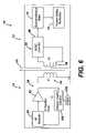
- FIG. 6illustrates a schematic representation of the shunt valve system of FIG. 1 , according to one embodiment of the invention.
- FIG. 7illustrates a schematic representation of the shunt valve system of FIG. 1 , according to one embodiment of the invention.
- Embodiments of the present inventionprovide an electromechanical brake mechanism that locks or secures a position of a pressure setting mechanism within a shunt valve assembly.
- the electromechanical brakecan maintain the position of the pressure setting mechanism in the presence of a relatively strong magnetic field, such as produced by a magnetic resonance imaging device, to maintain a set pressure differential within the shunt valve assembly.
- the shunt valverequires repositioning of the pressure setting mechanism within the shunt valve assembly to adjust a fluid flow rate through the shunt valve assembly.
- a cliniciancan activate an external controller to non-invasively release the electromagnetic brake mechanism from the pressure setting mechanism. When activated, the external controller transmits a radio frequency signal to the shunt valve assembly through magnetically coupled antennas between the controller and the shunt valve. The shunt valve assembly utilizes the signal to activate the braking mechanism and unlock the pressure setting mechanism. The clinician then operates the controller to non-invasively reposition the pressure setting mechanism and adjust the pressure at which the shunt valve opens:
- FIGS. 1 and 2illustrate an example of a shunt valve system 10 having a shunt valve assembly 12 and a controller 14 .
- the shunt valve assembly 12is operable to drain excess fluid from one area of a patient's body and direct the fluid to another site in the body.
- the shunt valve assembly 12includes a housing 16 defining an inlet port 18 , an outlet port 20 , and a chamber 22 oriented between the inlet port 18 and the outlet port 20 .
- the inlet port 18attaches to an inlet catheter 26 and the outlet port 20 attaches to a drainage catheter 28 .
- the inlet catheter 26inserts within a ventricle of a patient's brain and the drainage catheter 28 inserts within another area of the patient's body, such as the right atrium of the heart or the peritoneum.
- the shunt valve assembly 12carries cerebrospinal fluid (CSF), originating from the ventricle, from the inlet catheter 26 , through the chamber 22 , and to the drainage catheter 28 .
- CSFcerebrospinal fluid
- the shunt valve assembly 12includes a valve 30 having a pressure setting mechanism 32 .
- the valve 30 of the shunt valve assembly 12controls the flow of excess CSF from the ventricle of a brain to another area of a patient's body.
- the pressure setting mechanism 32is configured to provide non-invasive adjustment of the valve 30 within the housing 16 to adjust a pressure threshold within the shunt valve assembly 12 .
- the pressure setting mechanism 32includes at least one magnet that allows a user to non-invasively adjust a position of the pressure setting mechanism 32 . The user applies a strong external magnetic field to the shunt valve assembly 12 and rapidly switches the field to cause the pressure setting mechanism 32 to move or reposition within the housing 16 .
- Such repositioning of the pressure setting mechanism 32adjusts a pressure threshold at which fluid begins to flow through the shunt valve assembly 12 .
- the pressure setting mechanism 32therefore, ensures adequate fluid flow through the shunt valve assembly 12 and minimizes either overdrainage or underdrainage of CSF from a brain ventricle.
- the shunt valve assembly 12also includes an electromechanical brake 34 , which can include an actuator, such as a solenoid, a stepper motor, or piezo motor, configured to move a brake member secure a position of the pressure setting mechanism 32 within the housing 16 and maintain the pressure threshold within the shunt valve assembly 12 at a particular level.
- the electromechanical brake 34for example, has a brake member 46 that engages the pressure setting mechanism 32 to lock the relative position of the pressure setting mechanism 32 within the housing 16 .
- the electromechanical brake 34can effectively prevent movement of the pressure setting mechanism 32 relative to the housing 16 , such as when the pressure setting mechanism 32 is exposed to environmental magnetic forces.
- the shunt valve mechanism 12can be subjected to a strong external magnetic field, such as when a patient having an implanted shunt valve mechanism 12 undergoes an magnetic resonance imaging (MRI) procedure.
- the magnetic fieldgenerates a force on the magnetic pressure setting mechanism 32 within the shunt valve assembly 12 that induces motion of the pressure setting mechanism 32 within the housing 16 and can cause the pressure setting mechanism 32 to adjust the position of the valve 30 .
- the electromechanical brake 34preferably locks the pressure setting mechanism 32 in place to limit or prevent movement of the pressure setting mechanism 32 and to maintain a set pressure threshold within the shunt valve assembly 12 when exposed to the magnetic field. Additionally, the electromagnetic forces have little or no effect on the positioning of the brake member 46 of the electromechanical brake 34 .
- the electromechanical brake 34therefore, preferably maintains the relative position of the pressure setting mechanism 32 within the shunt valve assembly 12 , in the presence of the strong electromagnetic field, to maintain the set pressure threshold within the shunt valve assembly 12 .
- the valve 30can require periodic adjustment to ensure proper flow of fluid from a source (e.g., the patient's brain ventricle) to a destination (e.g., the patient's heart).
- a sourcee.g., the patient's brain ventricle
- a destinatione.g., the patient's heart
- the shunt valve mechanism 12is configured with a preset fluid pressure threshold (e.g., a preset position of the valve 30 and the pressure setting mechanism 32 within the housing 16 ).
- the brake member 46 of the electromechanical brake 34locks the position of the pressure setting mechanism 32 within the shunt valve apparatus 12 to maintain the preset fluid pressure threshold.
- the controller 14operates in conjunction with the shunt valve assembly 12 to non-invasively manipulate the electromechanical brake 34 and the relative positioning of the valve 30 within the housing 16 to adjust the pressure threshold within the shunt valve assembly 12 (e.g., to adjust a fluid pressure differential between the inlet port 18 and the outlet port 20 ).
- the controller 14includes a signal transmitter 38 and the shunt valve assembly 12 includes a signal receiver 36 electrically coupled to the electromechanical brake assembly 34 . Signals sent by the transmitter 38 to the receiver 36 allow for non-invasive control of the electromechanical brake assembly 34 . Additionally, the controller 14 includes a valve adjustment mechanism 40 , such as a magnetic element, configured to non-invasively operate the pressure setting mechanism 32 of the shunt valve assembly 12 to adjust the fluid pressure threshold within the shunt valve assembly 12 .
- a valve adjustment mechanism 40such as a magnetic element
- a userpositions the controller 14 in proximity to the body 44 , such as at a site 45 containing the shunt valve assembly 12 , to electromagnetically couple the signal transmitter 38 with the signal receiver 36 .
- the userthen activates the controller 14 to transmit an activation signal, such as a radio frequency signal, from the signal transmitter 38 to the signal receiver 36 .
- the signal receiver 36receives the activation signal and, in response to the signal, transmits a positioning signal to the electromechanical brake 32 .
- the positioning signalcauses the electromechanical brake 32 to disengage or retract the brake member 46 from the pressure setting mechanism 32 , thereby unlocking the pressure setting mechanism 32 .
- the useroperates the valve adjustment mechanism 40 of the controller 14 to non-invasively adjust the pressure setting mechanism 32 .
- the valve adjustment mechanism 40is formed as a magnetic element that applies a relatively strong magnetic field to the magnetic pressure setting mechanism 32 .
- the controller 14rapidly switches the magnetic field generated by the valve adjustment mechanism 40
- the pressure setting mechanism 32repositions within the housing 16 , to adjust the position of the valve 30 within the housing and alter the fluid pressure threshold within the shunt valve assembly 12 .
- the userdeactivates the signal transmitter 38 to discontinue transmission of the activation signal to the signal receiver 36 .
- the signal receiver 36ceases transmission of the positioning signal to the electromechanical brake assembly 34 , thereby causing the brake member 46 to reengage the pressure setting mechanism 32 .
- Such reengagementlocks the relative positions of the pressure setting mechanism 32 and the valve 30 within the housing 16 to maintain the pressure threshold within the shunt valve assembly 12 .
- FIGS. 1 and 2illustrate the electromechanical brake 34 used in conjunction with a generic valve 30 to control fluid flow within the shunt valve assembly 12 .
- the electromechanical brake 34can be used in a Hakim or ball-in-cone shunt valve mechanism, as disclosed by U.S. Pat. No. 4,615,691, the contents of which are hereby incorporated in its entirety by reference.
- FIG. 3illustrates the electromechanical brake 34 mounted within a Hakim shunt valve assembly 12 .
- the Hakim shunt valve assembly 12includes a valve 30 having a sphere 50 seated in a circular orifice 52 .
- the Hakim shunt valve assembly 12also includes a pressure setting mechanism 32 having a spring 54 , coupled to a cantilever 55 , and a rotor assembly 56 .
- the sphere 50regulates the pressure threshold at which fluid begins to flow through the shunt valve apparatus 12 .
- the sphere 50is operatively joined to a first end 60 of the cantilevered spring 54 while a second end 62 of the spring 54 engages a stair array 58 of the rotor assembly 56 .
- the rotor assembly 56includes the stair-step array 58 in the form of a spiral staircase.
- the stair array 58 of the rotor assembly 56can be smooth or can include friction-increasing surface features (not shown).
- the stair array 58can include virtually any surface feature that can increase the friction of the stair array 58 .
- suitable friction-increasing surface featuresinclude grooves, detents, ridges, corrugations, roughened surfaces and combinations thereof.
- the rotor assembly 56also includes at least one magnet carried in a rotor housing 68 . The magnet allows a clinician to non-invasively adjust the positioning of rotor assembly 56 to set the fluid pressure threshold in the shunt valve assembly 12 , as will be described in detail below.
- the ball-in-cone shunt valve assembly 12also includes an electromechanical brake 34 configured as a solenoid 63 having a magnetic brake member 64 and a spring 65 surrounding a shaft of the magnetic brake member 64 .
- the spring 65biases the brake member 64 toward the rotor assembly 56 to engage a wall 66 of the rotor assembly 56 and lock the rotor 56 within the shunt valve assembly 12 .
- the brake member 64inserts within the stair array 58 of the rotor assembly 56 to lock the relative position rotor assembly 56 . Engagement of the brake member 64 with the rotor 56 effectively prevents the rotor assembly 56 from rotating within the housing 16 of the shunt valve mechanism 12 , such as might be caused by external magnetic forces.
- the ball-in-cone shunt valve assembly 12can be used in conjunction with a controller 14 to allow a clinician to non-invasively adjust the pressure threshold of the shunt valve assembly 12 .
- the shunt valve assembly 12includes a signal receiver 36 and a signal processor 37 in electrical communication with the solenoid 63 via coupling device 35 .
- the clinicianpositions the controller 14 in proximity to the ball-in-cone shunt valve assembly 12 to electromagnetically couple the signal transmitter 38 of the controller 14 with the signal receiver 36 .
- the clinicianactivates the controller 14 to transmit an activation signal, such as a radio frequency signal, from the signal transmitter 38 to the signal receiver 36 .
- the signal receiver 36receives the activation signal and, in response to the activation signal, causes the signal processor 37 to transmit a positioning signal to the electromechanical brake 34 .
- the positioning signalcauses the electromechanical brake 34 to disengage or retract the brake member 64 from the rotor assembly 56 .
- the positioning signalcauses the solenoid 63 to generate a magnetic field, relative to the brake member 64 .
- the magnetic fieldin turn, generates a force on the brake member 64 , along a +X direction 70 , sufficient to overcome a spring force of the spring 65 and retract the brake member 64 from the rotor assembly 56 .
- the clinicianoperates the valve adjustment mechanism 40 of the controller 14 to non-invasively adjust rotor assembly 56 .
- the rotor assembly 56includes at least one magnet carried in a rotor housing 68 .
- the valve adjustment mechanism 40is formed as a magnetic element that applies a relatively strong magnetic field to the magnet carried in a rotor housing 68 .
- the controller 14rapidly switches the magnetic field generated by the valve adjustment mechanism 40 the rotor assembly 56 rotates within the shunt valve assembly 12 to change the pressure threshold of the shunt valve assembly 12 .
- the second end 62 of the spring 54moves up or down each stair of the spiral stair array 58 .
- the change in the angle of deflection of the spring 54(e.g., relative to the cantilever 55 ), in turn, alters the force that is exerted by the spring 54 on the sphere 50 .
- a change in the force applied by the spring 54 to the sphere 50results in a corresponding increase or decrease of the established pressure threshold at which fluid begins to flow through the shunt valve apparatus 12 .
- the cliniciandeactivates the signal transmitter 38 to discontinue transmission of the activation signal to the signal receiver 36 .
- the solenoid 63In the absence of a positioning signal transmitted from the signal receiver 36 to the solenoid 63 , the solenoid 63 to withhold a magnetic field, relative to the brake member 64 . This causes the spring 65 to expand and position the brake member 64 against the rotor 56 , as illustrated in FIG. 4 , to lock the position of the rotor 56 and maintain the adjusted pressure threshold within the shunt valve apparatus 12 .
- a controller 14transmits an activation signal to the shunt valve assembly 12 , via a signal transmitter 38 to control operation of the electromechanical brake 34 .
- the shunt valve assembly 12receives the activation signal, via the signal receiver 36 and, in response, transmits a positioning signal to the electromechanical brake 34 .
- the positioning signaladjusts a position of a brake member 46 of the electromechanical brake 34 , relative to the pressure setting mechanism 32 of the shunt valve assembly 12 .
- the electromechanical brake 34retracts the brake member 46 from the pressure setting mechanism 32 . This positioning allows a user to operate the pressure setting mechanism 32 and adjust a position of the valve 30 of the shunt valve assembly 12 .
- the signal transmitter 38 of the controller 14 and the signal receiver 36 of the shunt valve assembly 12are inductively coupled.
- FIG. 6illustrates an embodiment of the shunt valve system 10 where the controller 14 inductively couples to the shunt valve assembly 12 in order to non-invasively operate the electromechanical brake 34 of the shunt valve assembly 12 .
- the signal transmitter 38 of the controller 14includes a signal generator 90 , a signal amplifier 92 electrically connected to the signal generator 90 , and an inductive coupling mechanism 94 electrically connected to the signal amplifier 92 .
- the signal generator 90 of the controller 14in one arrangement, is a radio frequency signal generator.
- the signal generator 90provides or generates a radio frequency signal such as a radio frequency sine wave or a pulse wave signal.
- the signal generator 90provides the radio frequency signal to the signal amplifier 92 .
- the signal amplifier 92is a radio frequency amplifier configured to amplify signals within the radio frequency range.
- the inductive coupling mechanism 94for example, is an antenna formed as a wire coil having multiple windings.
- the signal receiver 36includes an inductive coupling mechanism 96 and a signal converter 98 electrically connected to both the inductive coupling mechanism 96 and the electromechanical brake 34 , such as a solenoid.
- the inductive coupling mechanism 96 of the shunt valve assembly 12for example, is an antenna formed as a wire coil having multiple windings.
- the inductive coupling mechanism 96is configured to inductively couple with the inductive coupling mechanism 94 of the controller 14 to receive an activation signal from the controller 14 .
- the signal converter 98receives the activation signal from the inductive coupling mechanism 96 and converts the activation signal to a positioning signal to operate the electromechanical brake 34 , as described in detail below.
- a userinductively couples the controller 14 to the shunt valve assembly 12 by way of the inductive coupling mechanisms 94 , 96 .
- the userpositions the controller 14 in relatively close proximity to the shunt valve assembly 12 .
- the usercan orient the inductive coupling mechanism 94 at a distance 99 between approximately 2.0 cm and 5.0 cm relative to the inductive coupling mechanism 96 of the shunt valve assembly 12 .
- Such relative proximity of the inductive coupling mechanisms 94 , 96provides adequate inductive coupling between the controller 14 and the shunt valve assembly 12 and limits the ability for electromagnetic interference from other sources from inadvertently causing operation of the electromechanical brake 34 .
- the signal generator 90As the user positions the controller 14 in proximity to the shunt valve assembly 12 the user activates the signal generator 90 of the controller 14 .
- the signal generator 90generates a pulse wave radio frequency signal and transmits the signal to the radio frequency amplifier 92 .
- the signal amplifier 92then amplifies the pulse wave signal and delivers the pulse wave signal to the inductive coupling mechanism 94 .
- the inductive coupling mechanisms 94 of the controller 14carries the pulse wave signal
- the inductive coupling mechanisms 94induces a second, corresponding pulse wave signal within the inductive coupling mechanisms 96 of the shunt valve assembly 12 .
- the inductive coupling mechanisms 96transmits the pulse wave signal (e.g., alternating current) to the signal converter 98 , which, in turn, converts the alternating current into a DC voltage to operate to the electromechanical brake 34 .
- the DC voltagecauses the brake member 46 of the brake assembly to disengage or position away from the valve 30 of the shunt valve assembly 12 .
- the electromechanical brake 34is a solenoid 63 having a brake member 64 (e.g., illustrated in FIGS. 4 and 5 )
- the solenoid 63receives the voltage
- the solenoid 63generates a magnetic field that causes the brake member 64 to disengage from the valve 30 (e.g., disengage from the rotor 56 or pressure setting mechanism 32 ).
- Such disengagementreleases the pressure setting mechanism 32 and allows the controller 14 to further adjust, non-invasively, the position of the pressure setting mechanism 32 within the shunt valve assembly 12 to adjust a fluid pressure threshold of the shunt valve assembly 12 .
- the controller 14includes an induction coupling detector 100 in electrical connection with the inductive coupling mechanism 94 of the controller 14 .
- the induction coupling detector 100includes a controller, such as a memory and a processor, configured to measure an inductive coupling value associated with the inductive coupling mechanism 94 of the controller 14 . Based on the measurement, the induction coupling detector 100 detects the quality or strength of the inductive coupling between the inductive coupling mechanisms 94 , 96 and can provide a warning to a user relating to the inductive coupling strength.
- the induction coupling detector 100measures an impedance value associated with the transmitter inductive coupling mechanism 94 as the inductive coupling value. For example, as the transmitter inductive coupling mechanism (e.g., transmitter) 94 induces a current in the receiver inductive coupling mechanism (e.g., receiver) 96 , the receiver 96 acts as a load on the transmitter 94 , thereby affecting the impedance of the transmitter 94 .
- the detector 100compares the impedance value with a threshold impedance value. For example, the induction coupling detector 100 stores the threshold impedance value within a memory location associated with the detector 100 .
- the detector 100mathematically relates the measured impedance value with the threshold impedance value to form a comparison result. Based upon the comparison result, the induction coupling detector 100 generates and transmits an output signal to an output mechanism 102 associated with the controller 14 to indicate the relative strength of the inductive coupling between the transmitter 94 and the receiver 96 .
- the output mechanism 102converts the output signal into an audio or visual indicator relating to the strength of the inductive coupling between the controller 14 and the shunt valve mechanism 12 .
- the detector 100generates an output signal that indicates a relatively strong inductive coupling between the controller 14 and the shunt valve mechanism 12 .
- the output mechanism 102can provide a user with an audio or visual indication to that indicates adequate inductive coupling of the controller 14 and the shunt valve mechanism 12 .
- the detector 100generates an output signal that indicates a relatively weak inductive coupling between the controller 14 and the shunt valve mechanism 12 .
- the output mechanism 102can provide a user with an audio or visual indication to that indicates inadequate inductive coupling of the controller 14 and the shunt valve mechanism 12 .
- the output mechanism 102can provide a user with an audio or visual warning indicating that the user position the controller 14 in closer proximity to the shunt valve mechanism 12 to increase the strength of the inductive coupling between the transmitter 94 and receiver 96 .
- the induction coupling detector 100detects a relatively weak inductive coupling between the transmitter 94 and the receiver 96 , the inductive coupling detector 100 generates an output signal that warns the user of the relatively weak inductive coupling between the transmitter 94 and the receiver 96 .
- the warning signalcauses the user to reposition the controller 14 relative to the shunt valve mechanism 12 to increase the inductive coupling between the transmitter 94 and receiver 96 .
- the induction coupling detector 100operates to electrically adjust the impedance of the transmitter 94 to increase the inductive coupling strength between the transmitter 94 and the receiver 96 without requiring the user to reposition the controller 14 relative to the shunt valve assembly 12 .
- the signal generator 90has a feedback loop with the induction coupling detector 100 and the transmitter 94 .
- the induction coupling detector 100controls the amount of power generated by the generator 90 upon a comparison between the detected impedance of the transmitter 94 and a threshold impedance value. Such control affects a strength of the pulse wave signal produced by the signal generator 90 that, in turn, adjusts an amount of energy or power transmitted through the inductive coupling between the transmitter 94 and the receiver 96 .
- the induction coupling detector 100detects a fairly weak inductive coupling between the transmitter 94 and the receiver 96 . In response to such detection, the inductive coupling detector 100 sends a signal to the signal generator 90 causing an increase of the power transmitted from the inductively coupled transmitter 94 to receiver 96 . During operation, the induction coupling detector 100 continuously measures the impedance of the transmitter 94 and adjusts the output of the generator 90 to the known appropriate value stored in a memory of the induction coupling detector 100 .
- the use of the electromechanical brake assembly 34 within the shunt valve assembly 12locks a position of a pressure setting mechanism 32 to minimize inadvertent repositioning of the pressure setting mechanism 32 or the valve 30 in the presence of strong external magnetic fields.
- the electromechanical brake assembly 34therefore, can minimize either overdrainage or underdrainage of CSF from a brain ventricle.
- the shunt valvecan include additional safety feature to minimize or prevent inadvertent release of the brake member 46 of the electromechanical brake 34 relative to the pressure setting mechanism 32 .
- FIG. 7illustrates an embodiment of the shunt valve system 10 where the shunt valve assembly 12 includes an activation signal coder 106 and an activation signal decoder 108 that minimizes or prevents inadvertent release of the brake member 46 of the electromechanical brake 34 .
- the activation signal coder 106 of the controller 14includes a second signal generator 110 and a shift key modulator 112 electrically connected to the second signal generator 110 .
- the second signal generator 110for example, is a radio frequency signal generator configured to generate a pulse wave or sine wave signal.
- the shift key modulator 112receives the pulse wave from the second signal generator 10 and converts the pulse wave signal to a shift key coded signal.
- the activation signal decoder 108 of the shunt valve assembly 112includes a signal decoder 114 electrically connected to a signal gate 116 .
- the signal decoder 114is configured to receive the coded signal from the receiver 96 and decode the coded signal into a latch signal (e.g., an on/off signal).
- the signal gate 116is configured to receive the latch signal from the signal decoder 114 and, based upon the latch signal, either allow or prevent operation of the electromechanical brake 34 .
- the first signal generator 90generates a sine wave signal and delivers the sine wave signal, as an activation signal, to the signal amplifier 92 .
- the second signal generator 110generates a sine wave signal and delivers the signal to the modulator 112 .
- the modulator 112encodes the signal by converting the signal to an amplitude or phase shift key modulated sine wave signal having a particular coded pattern (e.g., a pattern of 0's and 1's).
- the modulator 112also transmits the encoded signal to the signal amplifier 92 .
- the signal amplifier 92delivers both the activation signal, from the first signal generator 90 , and the encoded signal, from the signal modulator 112 , to the transmitter 94 .
- the transmitter 94transmits both signals to the receiver 96 , via inductive coupling between the transmitter 94 and the receiver 96 .
- the receiver 96transfers the activation signal to the signal converter 98 and transfers the coded signal to the signal decoder 114 .
- the signal converter 98receives the activation signal (e.g., an alternating current) the signal converter 90 converts the activation signal into a DC voltage signal and transmits the DC voltage signal to the gate 116 .
- the decoderconverts the encoded signal into a latch signal (e.g., an on/off signal) and transmits the latch signal to the gate 116 .
- the gate 116either allows or disallows passage of the DC voltage signal to the electromechanical brake 94 .
- the gate 116allows the DC voltage signal to pass to and operate the electromechanical brake.
- the gate 116does not allow the DC voltage signal to pass to the electromechanical brake 34 .
- the use of the coded signalprovides an additional safety feature to the shunt valve system 10 .
- an external magnetic or electrical fieldcan generate a voltage within the shunt valve mechanism 12 that could potentially cause inadvertent activation of the electromechanical brake 34 .
- the gate 116 of the shunt valve assembly of FIG. 7does not allow the voltage to pass to the electromechanical brake 34 .
- the use of the coded signal with the shunt valve system 10therefore, minimizes or prevents inadvertent activation of the electromechanical brake 34 and maintains a fluid pressure threshold within the shunt valve mechanism 12 .
- the transmittertransmits two separate signals to the receiver: an activation signal and a coded signal.
- the controllerincludes a single signal generation electrically connected to the signal modulator 112 .
- the signal modulatorencodes the activation signal.
- the transmitter 94transmits a single signal, the encoded activation signal, to the shunt valve assembly 12 for decoding.
- the shunt valve assembly 12includes a separate signal receiver 96 and a signal converter 98 .
- the signal receiver 96is configured to receive an activation signal from a controller 14 .
- the signal converter 98is configured to receive the activation signal (e.g., an alternating current) from the receiver 96 and convert the activation signal into a DC voltage signal.
- the signal receiver 96 and signal converter 98form part of a single multifunction sensor or microprocessor, such as described in U.S. Provisional Application entitled “Pressure Sensing Methods and Devices”, Ser. No. 60/661,758, filed on Mar. 15, 2005.
Landscapes
- Health & Medical Sciences (AREA)
- Engineering & Computer Science (AREA)
- Biomedical Technology (AREA)
- General Engineering & Computer Science (AREA)
- Animal Behavior & Ethology (AREA)
- General Health & Medical Sciences (AREA)
- Anesthesiology (AREA)
- Heart & Thoracic Surgery (AREA)
- Hematology (AREA)
- Life Sciences & Earth Sciences (AREA)
- Ophthalmology & Optometry (AREA)
- Otolaryngology (AREA)
- Public Health (AREA)
- Veterinary Medicine (AREA)
- Neurology (AREA)
- Mechanical Engineering (AREA)
- External Artificial Organs (AREA)
- Infusion, Injection, And Reservoir Apparatuses (AREA)
- Prostheses (AREA)
- Magnetically Actuated Valves (AREA)
Abstract
Description
Claims (24)
Priority Applications (7)
| Application Number | Priority Date | Filing Date | Title |
|---|---|---|---|
| US11/170,795US7334594B2 (en) | 2005-06-29 | 2005-06-29 | Apparatus and method for adjusting a locking mechanism of a shunt valve |
| CO06058535ACO5780140A1 (en) | 2005-06-29 | 2006-06-15 | APPLIANCE AND METHOD TO ADJUST A SECURING MECHANISM OF A DIVIDING VALVE |
| CA2550794ACA2550794C (en) | 2005-06-29 | 2006-06-22 | Apparatus and method for adjusting a locking mechanism of a shunt valve |
| JP2006178616AJP4550023B2 (en) | 2005-06-29 | 2006-06-28 | Apparatus and method for adjusting shunt valve locking mechanism |
| EP20060253362EP1738792B1 (en) | 2005-06-29 | 2006-06-28 | Apparatus and method for adjusting a locking mechanism of a shunt valve |
| DE200660002558DE602006002558D1 (en) | 2005-06-29 | 2006-06-28 | Device and method for closing a lock of a shunt valve |
| AU2006202764AAU2006202764B2 (en) | 2005-06-29 | 2006-06-29 | Apparatus and method for adjusting a locking mechanism of a shunt valve |
Applications Claiming Priority (1)
| Application Number | Priority Date | Filing Date | Title |
|---|---|---|---|
| US11/170,795US7334594B2 (en) | 2005-06-29 | 2005-06-29 | Apparatus and method for adjusting a locking mechanism of a shunt valve |
Publications (2)
| Publication Number | Publication Date |
|---|---|
| US20070005000A1 US20070005000A1 (en) | 2007-01-04 |
| US7334594B2true US7334594B2 (en) | 2008-02-26 |
Family
ID=36782309
Family Applications (1)
| Application Number | Title | Priority Date | Filing Date |
|---|---|---|---|
| US11/170,795Expired - Fee RelatedUS7334594B2 (en) | 2005-06-29 | 2005-06-29 | Apparatus and method for adjusting a locking mechanism of a shunt valve |
Country Status (7)
| Country | Link |
|---|---|
| US (1) | US7334594B2 (en) |
| EP (1) | EP1738792B1 (en) |
| JP (1) | JP4550023B2 (en) |
| AU (1) | AU2006202764B2 (en) |
| CA (1) | CA2550794C (en) |
| CO (1) | CO5780140A1 (en) |
| DE (1) | DE602006002558D1 (en) |
Cited By (59)
| Publication number | Priority date | Publication date | Assignee | Title |
|---|---|---|---|---|
| US20060183985A1 (en)* | 2004-07-13 | 2006-08-17 | Mark Brister | Analyte sensor |
| US20080125690A1 (en)* | 2006-09-24 | 2008-05-29 | Delaporte Stephen E | Electroactive polymer actuated cerebrospinal fluid shunt |
| US20080197024A1 (en)* | 2003-12-05 | 2008-08-21 | Dexcom, Inc. | Analyte sensor |
| US20090048648A1 (en)* | 2007-08-17 | 2009-02-19 | Searete Llc, A Limited Liability Corporation Of The State Of Delaware | Self-sterilizing device |
| US20090117001A1 (en)* | 2007-08-17 | 2009-05-07 | Searete Llc, A Limited Liability Corporation Of The State Of Delaware | Event-triggered ultraviolet light sterilization of surfaces |
| US20090124964A1 (en)* | 2003-12-05 | 2009-05-14 | Dexcom, Inc. | Integrated device for continuous in vivo analyte detection and simultaneous control of an infusion device |
| US20090131777A1 (en)* | 2006-10-04 | 2009-05-21 | Dexcom, Inc. | Analyte sensor |
| US20090131776A1 (en)* | 2006-10-04 | 2009-05-21 | Dexcom, Inc. | Analyte sensor |
| US20090131768A1 (en)* | 2006-10-04 | 2009-05-21 | Dexcom, Inc. | Analyte sensor |
| US20090131769A1 (en)* | 2006-10-04 | 2009-05-21 | Dexcom, Inc. | Analyte sensor |
| US20090137887A1 (en)* | 2006-10-04 | 2009-05-28 | Dexcom, Inc. | Analyte sensor |
| US20090163964A1 (en)* | 2007-08-17 | 2009-06-25 | Searete Llc, A Limited Liability Corporation Of The State Of Delaware | System, devices, and methods including sterilizing excitation delivery implants with general controllers and onboard power |
| US20090177254A1 (en)* | 2007-08-17 | 2009-07-09 | Searete Llc, A Limited Liability Of The State Of The State Of Delaware | System, devices, and methods including actively-controllable electrostatic and electromagnetic sterilizing excitation delivery system |
| US20090178459A1 (en)* | 2003-08-01 | 2009-07-16 | Dexcom, Inc. | Analyte sensor |
| US20090182217A1 (en)* | 2003-12-05 | 2009-07-16 | Dexcom, Inc. | Analyte sensor |
| US7615007B2 (en) | 2006-10-04 | 2009-11-10 | Dexcom, Inc. | Analyte sensor |
| US20100008822A1 (en)* | 2008-07-11 | 2010-01-14 | Searete Llc, A Limited Liability Corporation Of The State Of Delaware | Event-triggered self-sterilization of article surfaces |
| US20100174346A1 (en)* | 2007-08-17 | 2010-07-08 | Boyden Edward S | System, devices, and methods including actively-controllable sterilizing excitation delivery implants |
| US7783333B2 (en) | 2004-07-13 | 2010-08-24 | Dexcom, Inc. | Transcutaneous medical device with variable stiffness |
| US20100234793A1 (en)* | 2007-08-17 | 2010-09-16 | Searete Llc, A Limited Liability Corporation Of The State Of Delaware | Systems, devices and methods including infection-fighting and monitoring shunts |
| US20100305493A1 (en)* | 2007-05-17 | 2010-12-02 | Centrax Limited | Device for Controlling the Rate of Flow of a Fluid |
| US20110112460A1 (en)* | 2009-11-09 | 2011-05-12 | Medtronic Xomed, Inc. | Adjustable valve setting with motor control |
| US20110144566A1 (en)* | 2007-08-17 | 2011-06-16 | Searete Llc, A Limited Liability Corporation Of The State Of Delaware | Systems, devices, and methods including catheters having an actively controllable therapeutic agent delivery component |
| US20110152978A1 (en)* | 2008-12-04 | 2011-06-23 | Searete Llc, A Limited Liability Corporation Of The State Of Delaware | Systems, devices, and methods including catheters configured to monitor biofilm formation having biofilm spectral information configured as a data structure |
| US20110152750A1 (en)* | 2007-08-17 | 2011-06-23 | Searete Llc, A Limited Liability Corporation Of The State Of Delaware | Systems devices, and methods including catheters configured to monitor and inhibit biofilm formation |
| US20110152789A1 (en)* | 2007-08-17 | 2011-06-23 | Searete Llc, A Limited Liability Corporation Of The State Of Delaware | Systems, devices, and methods including catheters having components that are actively controllable between two or more wettability states |
| US20110152751A1 (en)* | 2008-12-04 | 2011-06-23 | Searete Llc, A Limited Liability Corporation Of The State Of Delaware | Systems, devices, and methods including catheters having UV-Energy emitting coatings |
| US20110160644A1 (en)* | 2007-08-17 | 2011-06-30 | Searete Llc, A Limited Liability Corporation Of The State Of Delaware | Systems, devices, and methods including catheters configured to release ultraviolet energy absorbing agents |
| US20110160643A1 (en)* | 2007-08-17 | 2011-06-30 | Searete Llc, A Limited Liability Corporation Of The State Of Delaware | Systems, devices, and methods including catheters having acoustically actuatable waveguide components for delivering a sterilizing stimulus to a region proximate a surface of the catheter |
| US8162924B2 (en) | 2007-08-17 | 2012-04-24 | The Invention Science Fund I, Llc | System, devices, and methods including actively-controllable superoxide water generating systems |
| US8322365B2 (en) | 2010-08-17 | 2012-12-04 | Codman & Shurtleff, Inc. | Implantable adjustable valve |
| US8364231B2 (en) | 2006-10-04 | 2013-01-29 | Dexcom, Inc. | Analyte sensor |
| US8364230B2 (en) | 2006-10-04 | 2013-01-29 | Dexcom, Inc. | Analyte sensor |
| US8396528B2 (en) | 2008-03-25 | 2013-03-12 | Dexcom, Inc. | Analyte sensor |
| US8425416B2 (en) | 2006-10-04 | 2013-04-23 | Dexcom, Inc. | Analyte sensor |
| US8447376B2 (en) | 2006-10-04 | 2013-05-21 | Dexcom, Inc. | Analyte sensor |
| US8460229B2 (en) | 2007-08-17 | 2013-06-11 | The Invention Science Fund I, Llc | Systems, devices, and methods including catheters having components that are actively controllable between transmissive and reflective states |
| US8562558B2 (en) | 2007-06-08 | 2013-10-22 | Dexcom, Inc. | Integrated medicament delivery device for use with continuous analyte sensor |
| US8706211B2 (en) | 2007-08-17 | 2014-04-22 | The Invention Science Fund I, Llc | Systems, devices, and methods including catheters having self-cleaning surfaces |
| US8886273B2 (en) | 2003-08-01 | 2014-11-11 | Dexcom, Inc. | Analyte sensor |
| US9101678B2 (en) | 2011-11-03 | 2015-08-11 | Elwha Llc | Heat-sanitization of surfaces |
| US9126010B2 (en) | 2013-03-14 | 2015-09-08 | Medtronic Xomed, Inc. | Device and method for finding the center and reading the setting of an implantable medical device |
| US9149615B2 (en) | 2010-08-17 | 2015-10-06 | DePuy Synthes Products, Inc. | Method and tools for implanted device |
| US9295826B2 (en) | 2012-06-21 | 2016-03-29 | Medtronic Xomed, Inc. | Fluid flow control devices, rotors and magnets with increased resistance to inadvertent setting change and improved accessory tool coupling |
| US9474831B2 (en) | 2008-12-04 | 2016-10-25 | Gearbox, Llc | Systems, devices, and methods including implantable devices with anti-microbial properties |
| US10183143B2 (en) | 2013-03-15 | 2019-01-22 | Bitol Designs, Llc | Occlusion resistant catheter and method of use |
| US10322267B2 (en) | 2013-03-15 | 2019-06-18 | Carlos A. Hakim | Externally programmable valve assembly |
| US10524703B2 (en) | 2004-07-13 | 2020-01-07 | Dexcom, Inc. | Transcutaneous analyte sensor |
| US10610136B2 (en) | 2005-03-10 | 2020-04-07 | Dexcom, Inc. | System and methods for processing analyte sensor data for sensor calibration |
| US10813577B2 (en) | 2005-06-21 | 2020-10-27 | Dexcom, Inc. | Analyte sensor |
| US10835672B2 (en) | 2004-02-26 | 2020-11-17 | Dexcom, Inc. | Integrated insulin delivery system with continuous glucose sensor |
| US10966609B2 (en) | 2004-02-26 | 2021-04-06 | Dexcom, Inc. | Integrated medicament delivery device for use with continuous analyte sensor |
| US10980461B2 (en) | 2008-11-07 | 2021-04-20 | Dexcom, Inc. | Advanced analyte sensor calibration and error detection |
| US11000215B1 (en) | 2003-12-05 | 2021-05-11 | Dexcom, Inc. | Analyte sensor |
| US11246990B2 (en) | 2004-02-26 | 2022-02-15 | Dexcom, Inc. | Integrated delivery device for continuous glucose sensor |
| US11331022B2 (en) | 2017-10-24 | 2022-05-17 | Dexcom, Inc. | Pre-connected analyte sensors |
| US11350862B2 (en) | 2017-10-24 | 2022-06-07 | Dexcom, Inc. | Pre-connected analyte sensors |
| US11399745B2 (en) | 2006-10-04 | 2022-08-02 | Dexcom, Inc. | Dual electrode system for a continuous analyte sensor |
| US11633133B2 (en) | 2003-12-05 | 2023-04-25 | Dexcom, Inc. | Dual electrode system for a continuous analyte sensor |
Families Citing this family (23)
| Publication number | Priority date | Publication date | Assignee | Title |
|---|---|---|---|---|
| US20030216710A1 (en)* | 2002-03-26 | 2003-11-20 | Hurt Robert F. | Catheter |
| US9694166B2 (en) | 2002-03-26 | 2017-07-04 | Medtronics Ps Medical, Inc. | Method of draining cerebrospinal fluid |
| US7585280B2 (en) | 2004-12-29 | 2009-09-08 | Codman & Shurtleff, Inc. | System and method for measuring the pressure of a fluid system within a patient |
| US8875714B2 (en)* | 2007-02-22 | 2014-11-04 | The Invention Science Fund I, Llc | Coded-sequence activation of surgical implants |
| US8123714B2 (en)* | 2007-06-29 | 2012-02-28 | Codman & Shurtleff, Inc. | Programmable shunt with electromechanical valve actuator |
| WO2009034410A1 (en)* | 2007-09-10 | 2009-03-19 | Sophysa | Device and method for mechanically locating and reading the setting of an adjustable valve |
| US8454524B2 (en) | 2007-10-31 | 2013-06-04 | DePuy Synthes Products, LLC | Wireless flow sensor |
| US7842004B2 (en)* | 2007-10-31 | 2010-11-30 | Codman & Shurtleff, Inc. | Wireless pressure setting indicator |
| US9204812B2 (en) | 2007-10-31 | 2015-12-08 | DePuy Synthes Products, LLC | Wireless pressure sensing shunts |
| US8480612B2 (en) | 2007-10-31 | 2013-07-09 | DePuy Synthes Products, LLC | Wireless shunts with storage |
| CN101918071B (en)* | 2007-11-23 | 2016-11-16 | 洛桑联邦理工学院 | Non-invasive adjustable drainage device |
| US8591499B2 (en)* | 2009-10-30 | 2013-11-26 | Medos International S.A.R.L. | Tools and methods for programming an implantable valve |
| US8398617B2 (en)* | 2009-10-30 | 2013-03-19 | Codman & Shurtleff, Inc. | Tools and methods for programming an implantable valve |
| DE102009060533B4 (en)* | 2009-12-23 | 2019-07-11 | Christoph Miethke Gmbh & Co Kg | Implantable shunt system |
| US20110198937A1 (en)* | 2010-02-15 | 2011-08-18 | Qualcomm Incorporated | Impedance neutral wireless power receivers |
| US8298168B2 (en)* | 2011-01-27 | 2012-10-30 | Medtronic Xomed, Inc. | Adjustment for hydrocephalus shunt valve |
| US9126009B2 (en)* | 2013-03-12 | 2015-09-08 | DePuy Synthes Products, Inc. | System and method for determining position and pressure of an implantable shunt |
| FR3010636B1 (en) | 2013-09-16 | 2015-10-02 | Sophysa Sa | ADJUSTABLE DRAINAGE VALVE |
| JP7208132B2 (en)* | 2016-08-12 | 2023-01-18 | ハキム,カーロス・エー | Externally programmable magnetic valve assembly and controller |
| US12420075B2 (en) | 2016-08-12 | 2025-09-23 | Ceredyn Biotechnology Llc | Externally programable magnetic valve assembly and controller |
| US10406331B2 (en)* | 2016-11-14 | 2019-09-10 | Integra Lifesciences Switzerland Sàrl | Device and method to locate and read an implanted device using ultrasound |
| AU2021202952A1 (en)* | 2020-05-21 | 2021-12-09 | Carlos A. Hakim | Externally programable magnetic valve assembly and controller |
| JP2023146366A (en)* | 2022-03-29 | 2023-10-12 | タキヒヨー株式会社 | cushion |
Citations (23)
| Publication number | Priority date | Publication date | Assignee | Title |
|---|---|---|---|---|
| US3886948A (en) | 1972-08-14 | 1975-06-03 | Hakim Co Ltd | Ventricular shunt having a variable pressure valve |
| US4332255A (en) | 1979-01-10 | 1982-06-01 | Hakim Company Limited | Shunt valve |
| US4387715A (en) | 1980-09-23 | 1983-06-14 | Hakim Company Limited | Shunt valve |
| US4443214A (en) | 1981-03-18 | 1984-04-17 | Society Dite: Sophysa | Valve for the treatment of hydrocephalus |
| US4532932A (en)* | 1984-01-03 | 1985-08-06 | Cordis Corporation | Implant communication system with frequency shift means |
| US4551128A (en) | 1983-05-11 | 1985-11-05 | Salomon Hakim | Cerebrospinal fluid shunt valve |
| US4595390A (en) | 1983-07-21 | 1986-06-17 | Salomon Hakim | Magnetically-adjustable cerebrospinal fluid shunt valve |
| US4615691A (en) | 1983-12-08 | 1986-10-07 | Salomon Hakim | Surgically-implantable stepping motor |
| US4772257A (en) | 1983-12-08 | 1988-09-20 | Salomon Hakim | External programmer for magnetically-adjustable cerebrospinal fluid shunt valve |
| US5637083A (en) | 1996-01-19 | 1997-06-10 | Pudenz-Schulte Medical Research Corporation | Implantable adjustable fluid flow control valve |
| US5643194A (en) | 1994-06-24 | 1997-07-01 | Sophysa | Subcutaneous valve and device for externally setting it |
| US5928182A (en) | 1997-07-02 | 1999-07-27 | Johnson & Johnson Professional, Inc. | Pediatric programmable hydrocephalus valve |
| EP0982048A1 (en) | 1998-03-12 | 2000-03-01 | Leonhardt, Steffen, Dr.-Ing. | Implant for controlled drainage of cerebrospinal fluid |
| US20010002250A1 (en) | 1998-03-03 | 2001-05-31 | Burbank Fred H. | Sentinel node location and biopsy |
| US20020026139A1 (en) | 2000-02-02 | 2002-02-28 | Bertrand William Jeff | Valve seat and valve |
| US20020058901A1 (en) | 2000-11-13 | 2002-05-16 | Bernard Marion | Implantable subcutaneous value for the treatment of hydrocephalus, and adjusting devices therefor |
| US20040010219A1 (en) | 2002-07-10 | 2004-01-15 | Mccusker Daniel | Shunt valve locking mechanism |
| US6702249B2 (en) | 2001-03-19 | 2004-03-09 | Seiko Instruments Inc. | Pressure-variable valve device and set-pressure adjusting device for the valve device |
| US20040143242A1 (en) | 2003-01-22 | 2004-07-22 | Lev Ludin | Troubleshooting accelerator system for implantable drug delivery pumps |
| US6926691B2 (en) | 2000-12-11 | 2005-08-09 | Christoph Miethke | Hydrocephalus valve |
| US20060074371A1 (en)* | 2004-09-30 | 2006-04-06 | Codman & Shurtleff, Inc. | High pressure range hydrocephalus valve system |
| US7066901B2 (en)* | 2001-04-20 | 2006-06-27 | Siemens Aktiengesellschaft | MR-compatible fluid valve |
| US20070004999A1 (en)* | 2002-12-11 | 2007-01-04 | Christoph Miethke | Method of treating a patient with hydrocephalus and apparatus therefor |
Family Cites Families (3)
| Publication number | Priority date | Publication date | Assignee | Title |
|---|---|---|---|---|
| JP3825054B2 (en)* | 1997-01-24 | 2006-09-20 | メドトロニック ピーエス メディカル | Implantable adjustable fluid flow control valve |
| JP2002022048A (en)* | 2000-07-06 | 2002-01-23 | Seiko Instruments Inc | Pressure variable valve device |
| DE50204596D1 (en)* | 2002-04-15 | 2005-11-24 | Murr Elektronik Gmbh | Piercing contact terminal |
- 2005
- 2005-06-29USUS11/170,795patent/US7334594B2/ennot_activeExpired - Fee Related
- 2006
- 2006-06-15COCO06058535Apatent/CO5780140A1/enunknown
- 2006-06-22CACA2550794Apatent/CA2550794C/ennot_activeExpired - Fee Related
- 2006-06-28DEDE200660002558patent/DE602006002558D1/enactiveActive
- 2006-06-28JPJP2006178616Apatent/JP4550023B2/ennot_activeExpired - Fee Related
- 2006-06-28EPEP20060253362patent/EP1738792B1/ennot_activeCeased
- 2006-06-29AUAU2006202764Apatent/AU2006202764B2/ennot_activeCeased
Patent Citations (24)
| Publication number | Priority date | Publication date | Assignee | Title |
|---|---|---|---|---|
| US3886948A (en) | 1972-08-14 | 1975-06-03 | Hakim Co Ltd | Ventricular shunt having a variable pressure valve |
| US4332255A (en) | 1979-01-10 | 1982-06-01 | Hakim Company Limited | Shunt valve |
| US4387715A (en) | 1980-09-23 | 1983-06-14 | Hakim Company Limited | Shunt valve |
| US4443214A (en) | 1981-03-18 | 1984-04-17 | Society Dite: Sophysa | Valve for the treatment of hydrocephalus |
| US4551128A (en) | 1983-05-11 | 1985-11-05 | Salomon Hakim | Cerebrospinal fluid shunt valve |
| US4595390A (en) | 1983-07-21 | 1986-06-17 | Salomon Hakim | Magnetically-adjustable cerebrospinal fluid shunt valve |
| US4615691A (en) | 1983-12-08 | 1986-10-07 | Salomon Hakim | Surgically-implantable stepping motor |
| US4772257A (en) | 1983-12-08 | 1988-09-20 | Salomon Hakim | External programmer for magnetically-adjustable cerebrospinal fluid shunt valve |
| US4532932A (en)* | 1984-01-03 | 1985-08-06 | Cordis Corporation | Implant communication system with frequency shift means |
| US5643194A (en) | 1994-06-24 | 1997-07-01 | Sophysa | Subcutaneous valve and device for externally setting it |
| US5637083A (en) | 1996-01-19 | 1997-06-10 | Pudenz-Schulte Medical Research Corporation | Implantable adjustable fluid flow control valve |
| US5928182A (en) | 1997-07-02 | 1999-07-27 | Johnson & Johnson Professional, Inc. | Pediatric programmable hydrocephalus valve |
| US20010002250A1 (en) | 1998-03-03 | 2001-05-31 | Burbank Fred H. | Sentinel node location and biopsy |
| EP0982048A1 (en) | 1998-03-12 | 2000-03-01 | Leonhardt, Steffen, Dr.-Ing. | Implant for controlled drainage of cerebrospinal fluid |
| US20020026139A1 (en) | 2000-02-02 | 2002-02-28 | Bertrand William Jeff | Valve seat and valve |
| US20020058901A1 (en) | 2000-11-13 | 2002-05-16 | Bernard Marion | Implantable subcutaneous value for the treatment of hydrocephalus, and adjusting devices therefor |
| US6840917B2 (en) | 2000-11-13 | 2005-01-11 | Bernard Marion | Implantable subcutaneous valve for the treatment of hydrocephalus, and adjusting devices therefor |
| US6926691B2 (en) | 2000-12-11 | 2005-08-09 | Christoph Miethke | Hydrocephalus valve |
| US6702249B2 (en) | 2001-03-19 | 2004-03-09 | Seiko Instruments Inc. | Pressure-variable valve device and set-pressure adjusting device for the valve device |
| US7066901B2 (en)* | 2001-04-20 | 2006-06-27 | Siemens Aktiengesellschaft | MR-compatible fluid valve |
| US20040010219A1 (en) | 2002-07-10 | 2004-01-15 | Mccusker Daniel | Shunt valve locking mechanism |
| US20070004999A1 (en)* | 2002-12-11 | 2007-01-04 | Christoph Miethke | Method of treating a patient with hydrocephalus and apparatus therefor |
| US20040143242A1 (en) | 2003-01-22 | 2004-07-22 | Lev Ludin | Troubleshooting accelerator system for implantable drug delivery pumps |
| US20060074371A1 (en)* | 2004-09-30 | 2006-04-06 | Codman & Shurtleff, Inc. | High pressure range hydrocephalus valve system |
Non-Patent Citations (1)
| Title |
|---|
| Search Report for EP 06 25 3362. |
Cited By (172)
| Publication number | Priority date | Publication date | Assignee | Title |
|---|---|---|---|---|
| US8626257B2 (en) | 2003-08-01 | 2014-01-07 | Dexcom, Inc. | Analyte sensor |
| US10052055B2 (en) | 2003-08-01 | 2018-08-21 | Dexcom, Inc. | Analyte sensor |
| US8886273B2 (en) | 2003-08-01 | 2014-11-11 | Dexcom, Inc. | Analyte sensor |
| US20090178459A1 (en)* | 2003-08-01 | 2009-07-16 | Dexcom, Inc. | Analyte sensor |
| US8425417B2 (en) | 2003-12-05 | 2013-04-23 | Dexcom, Inc. | Integrated device for continuous in vivo analyte detection and simultaneous control of an infusion device |
| US20080197024A1 (en)* | 2003-12-05 | 2008-08-21 | Dexcom, Inc. | Analyte sensor |
| US11020031B1 (en) | 2003-12-05 | 2021-06-01 | Dexcom, Inc. | Analyte sensor |
| US20090124964A1 (en)* | 2003-12-05 | 2009-05-14 | Dexcom, Inc. | Integrated device for continuous in vivo analyte detection and simultaneous control of an infusion device |
| US20090182217A1 (en)* | 2003-12-05 | 2009-07-16 | Dexcom, Inc. | Analyte sensor |
| US8287453B2 (en) | 2003-12-05 | 2012-10-16 | Dexcom, Inc. | Analyte sensor |
| US11633133B2 (en) | 2003-12-05 | 2023-04-25 | Dexcom, Inc. | Dual electrode system for a continuous analyte sensor |
| US11000215B1 (en) | 2003-12-05 | 2021-05-11 | Dexcom, Inc. | Analyte sensor |
| US10966609B2 (en) | 2004-02-26 | 2021-04-06 | Dexcom, Inc. | Integrated medicament delivery device for use with continuous analyte sensor |
| US12102410B2 (en) | 2004-02-26 | 2024-10-01 | Dexcom, Inc | Integrated medicament delivery device for use with continuous analyte sensor |
| US12115357B2 (en) | 2004-02-26 | 2024-10-15 | Dexcom, Inc. | Integrated delivery device for continuous glucose sensor |
| US10835672B2 (en) | 2004-02-26 | 2020-11-17 | Dexcom, Inc. | Integrated insulin delivery system with continuous glucose sensor |
| US12226617B2 (en) | 2004-02-26 | 2025-02-18 | Dexcom, Inc. | Integrated delivery device for continuous glucose sensor |
| US11246990B2 (en) | 2004-02-26 | 2022-02-15 | Dexcom, Inc. | Integrated delivery device for continuous glucose sensor |
| US11045120B2 (en) | 2004-07-13 | 2021-06-29 | Dexcom, Inc. | Analyte sensor |
| US10980452B2 (en) | 2004-07-13 | 2021-04-20 | Dexcom, Inc. | Analyte sensor |
| US8750955B2 (en) | 2004-07-13 | 2014-06-10 | Dexcom, Inc. | Analyte sensor |
| US10709362B2 (en) | 2004-07-13 | 2020-07-14 | Dexcom, Inc. | Analyte sensor |
| US10827956B2 (en) | 2004-07-13 | 2020-11-10 | Dexcom, Inc. | Analyte sensor |
| US10524703B2 (en) | 2004-07-13 | 2020-01-07 | Dexcom, Inc. | Transcutaneous analyte sensor |
| US7783333B2 (en) | 2004-07-13 | 2010-08-24 | Dexcom, Inc. | Transcutaneous medical device with variable stiffness |
| US10722152B2 (en) | 2004-07-13 | 2020-07-28 | Dexcom, Inc. | Analyte sensor |
| US10709363B2 (en) | 2004-07-13 | 2020-07-14 | Dexcom, Inc. | Analyte sensor |
| US11064917B2 (en) | 2004-07-13 | 2021-07-20 | Dexcom, Inc. | Analyte sensor |
| US10799159B2 (en) | 2004-07-13 | 2020-10-13 | Dexcom, Inc. | Analyte sensor |
| US10813576B2 (en) | 2004-07-13 | 2020-10-27 | Dexcom, Inc. | Analyte sensor |
| US11026605B1 (en) | 2004-07-13 | 2021-06-08 | Dexcom, Inc. | Analyte sensor |
| US10918313B2 (en) | 2004-07-13 | 2021-02-16 | Dexcom, Inc. | Analyte sensor |
| US10799158B2 (en) | 2004-07-13 | 2020-10-13 | Dexcom, Inc. | Analyte sensor |
| US11883164B2 (en) | 2004-07-13 | 2024-01-30 | Dexcom, Inc. | System and methods for processing analyte sensor data for sensor calibration |
| US10918315B2 (en) | 2004-07-13 | 2021-02-16 | Dexcom, Inc. | Analyte sensor |
| US7857760B2 (en) | 2004-07-13 | 2010-12-28 | Dexcom, Inc. | Analyte sensor |
| US10918314B2 (en) | 2004-07-13 | 2021-02-16 | Dexcom, Inc. | Analyte sensor |
| US10993642B2 (en) | 2004-07-13 | 2021-05-04 | Dexcom, Inc. | Analyte sensor |
| US10993641B2 (en) | 2004-07-13 | 2021-05-04 | Dexcom, Inc. | Analyte sensor |
| US7640048B2 (en) | 2004-07-13 | 2009-12-29 | Dexcom, Inc. | Analyte sensor |
| US20060183985A1 (en)* | 2004-07-13 | 2006-08-17 | Mark Brister | Analyte sensor |
| US10932700B2 (en) | 2004-07-13 | 2021-03-02 | Dexcom, Inc. | Analyte sensor |
| US11000213B2 (en) | 2005-03-10 | 2021-05-11 | Dexcom, Inc. | System and methods for processing analyte sensor data for sensor calibration |
| US10856787B2 (en) | 2005-03-10 | 2020-12-08 | Dexcom, Inc. | System and methods for processing analyte sensor data for sensor calibration |
| US10918316B2 (en) | 2005-03-10 | 2021-02-16 | Dexcom, Inc. | System and methods for processing analyte sensor data for sensor calibration |
| US10918318B2 (en) | 2005-03-10 | 2021-02-16 | Dexcom, Inc. | System and methods for processing analyte sensor data for sensor calibration |
| US10610135B2 (en) | 2005-03-10 | 2020-04-07 | Dexcom, Inc. | System and methods for processing analyte sensor data for sensor calibration |
| US10709364B2 (en) | 2005-03-10 | 2020-07-14 | Dexcom, Inc. | System and methods for processing analyte sensor data for sensor calibration |
| US10743801B2 (en) | 2005-03-10 | 2020-08-18 | Dexcom, Inc. | System and methods for processing analyte sensor data for sensor calibration |
| US10918317B2 (en) | 2005-03-10 | 2021-02-16 | Dexcom, Inc. | System and methods for processing analyte sensor data for sensor calibration |
| US10610137B2 (en) | 2005-03-10 | 2020-04-07 | Dexcom, Inc. | System and methods for processing analyte sensor data for sensor calibration |
| US10610136B2 (en) | 2005-03-10 | 2020-04-07 | Dexcom, Inc. | System and methods for processing analyte sensor data for sensor calibration |
| US10617336B2 (en) | 2005-03-10 | 2020-04-14 | Dexcom, Inc. | System and methods for processing analyte sensor data for sensor calibration |
| US11051726B2 (en) | 2005-03-10 | 2021-07-06 | Dexcom, Inc. | System and methods for processing analyte sensor data for sensor calibration |
| US10898114B2 (en) | 2005-03-10 | 2021-01-26 | Dexcom, Inc. | System and methods for processing analyte sensor data for sensor calibration |
| US10925524B2 (en) | 2005-03-10 | 2021-02-23 | Dexcom, Inc. | System and methods for processing analyte sensor data for sensor calibration |
| US10716498B2 (en) | 2005-03-10 | 2020-07-21 | Dexcom, Inc. | System and methods for processing analyte sensor data for sensor calibration |
| US10813577B2 (en) | 2005-06-21 | 2020-10-27 | Dexcom, Inc. | Analyte sensor |
| US20080125690A1 (en)* | 2006-09-24 | 2008-05-29 | Delaporte Stephen E | Electroactive polymer actuated cerebrospinal fluid shunt |
| US8211051B2 (en)* | 2006-09-24 | 2012-07-03 | Delaporte Stephen E | Electroactive polymer actuated cerebrospinal fluid shunt |
| US11382539B2 (en) | 2006-10-04 | 2022-07-12 | Dexcom, Inc. | Analyte sensor |
| US8911367B2 (en) | 2006-10-04 | 2014-12-16 | Dexcom, Inc. | Analyte sensor |
| US8364231B2 (en) | 2006-10-04 | 2013-01-29 | Dexcom, Inc. | Analyte sensor |
| US8425416B2 (en) | 2006-10-04 | 2013-04-23 | Dexcom, Inc. | Analyte sensor |
| US8447376B2 (en) | 2006-10-04 | 2013-05-21 | Dexcom, Inc. | Analyte sensor |
| US8449464B2 (en) | 2006-10-04 | 2013-05-28 | Dexcom, Inc. | Analyte sensor |
| US8298142B2 (en) | 2006-10-04 | 2012-10-30 | Dexcom, Inc. | Analyte sensor |
| US8478377B2 (en) | 2006-10-04 | 2013-07-02 | Dexcom, Inc. | Analyte sensor |
| US8532730B2 (en) | 2006-10-04 | 2013-09-10 | Dexcom, Inc. | Analyte sensor |
| US10349873B2 (en) | 2006-10-04 | 2019-07-16 | Dexcom, Inc. | Analyte sensor |
| US8562528B2 (en) | 2006-10-04 | 2013-10-22 | Dexcom, Inc. | Analyte sensor |
| US8275438B2 (en) | 2006-10-04 | 2012-09-25 | Dexcom, Inc. | Analyte sensor |
| US20090131777A1 (en)* | 2006-10-04 | 2009-05-21 | Dexcom, Inc. | Analyte sensor |
| US20100298684A1 (en)* | 2006-10-04 | 2010-11-25 | Dexcom, Inc. | Analyte sensor |
| US20090131776A1 (en)* | 2006-10-04 | 2009-05-21 | Dexcom, Inc. | Analyte sensor |
| US7775975B2 (en) | 2006-10-04 | 2010-08-17 | Dexcom, Inc. | Analyte sensor |
| US9451908B2 (en) | 2006-10-04 | 2016-09-27 | Dexcom, Inc. | Analyte sensor |
| US11399745B2 (en) | 2006-10-04 | 2022-08-02 | Dexcom, Inc. | Dual electrode system for a continuous analyte sensor |
| US20100081910A1 (en)* | 2006-10-04 | 2010-04-01 | Dexcom, Inc. | Analyte sensor |
| US20090287074A1 (en)* | 2006-10-04 | 2009-11-19 | Dexcom, Inc. | Analyte sensor |
| US7615007B2 (en) | 2006-10-04 | 2009-11-10 | Dexcom, Inc. | Analyte sensor |
| US8774886B2 (en) | 2006-10-04 | 2014-07-08 | Dexcom, Inc. | Analyte sensor |
| US20090131768A1 (en)* | 2006-10-04 | 2009-05-21 | Dexcom, Inc. | Analyte sensor |
| US20090137887A1 (en)* | 2006-10-04 | 2009-05-28 | Dexcom, Inc. | Analyte sensor |
| US20090131769A1 (en)* | 2006-10-04 | 2009-05-21 | Dexcom, Inc. | Analyte sensor |
| US8364230B2 (en) | 2006-10-04 | 2013-01-29 | Dexcom, Inc. | Analyte sensor |
| US8808223B2 (en)* | 2007-05-17 | 2014-08-19 | Centrax Limited | Device for controlling the rate of flow of a fluid |
| US20100305493A1 (en)* | 2007-05-17 | 2010-12-02 | Centrax Limited | Device for Controlling the Rate of Flow of a Fluid |
| US11373347B2 (en) | 2007-06-08 | 2022-06-28 | Dexcom, Inc. | Integrated medicament delivery device for use with continuous analyte sensor |
| US10403012B2 (en) | 2007-06-08 | 2019-09-03 | Dexcom, Inc. | Integrated medicament delivery device for use with continuous analyte sensor |
| US8562558B2 (en) | 2007-06-08 | 2013-10-22 | Dexcom, Inc. | Integrated medicament delivery device for use with continuous analyte sensor |
| US12394120B2 (en) | 2007-06-08 | 2025-08-19 | Dexcom, Inc. | Integrated medicament delivery device for use with continuous analyte sensor |
| US9741139B2 (en) | 2007-06-08 | 2017-08-22 | Dexcom, Inc. | Integrated medicament delivery device for use with continuous analyte sensor |
| US20110160643A1 (en)* | 2007-08-17 | 2011-06-30 | Searete Llc, A Limited Liability Corporation Of The State Of Delaware | Systems, devices, and methods including catheters having acoustically actuatable waveguide components for delivering a sterilizing stimulus to a region proximate a surface of the catheter |
| US20110160644A1 (en)* | 2007-08-17 | 2011-06-30 | Searete Llc, A Limited Liability Corporation Of The State Of Delaware | Systems, devices, and methods including catheters configured to release ultraviolet energy absorbing agents |
| US20090048648A1 (en)* | 2007-08-17 | 2009-02-19 | Searete Llc, A Limited Liability Corporation Of The State Of Delaware | Self-sterilizing device |
| US9687670B2 (en) | 2007-08-17 | 2017-06-27 | Gearbox, Llc | Systems, devices, and methods including infection-fighting and monitoring shunts |
| US20090117001A1 (en)* | 2007-08-17 | 2009-05-07 | Searete Llc, A Limited Liability Corporation Of The State Of Delaware | Event-triggered ultraviolet light sterilization of surfaces |
| US20090163965A1 (en)* | 2007-08-17 | 2009-06-25 | Searete Llc, A Limited Liability Corporation Of The State Of Delaware | System, devices, and methods including actively-controllable sterilizing excitation delivery implants |
| US20090163964A1 (en)* | 2007-08-17 | 2009-06-25 | Searete Llc, A Limited Liability Corporation Of The State Of Delaware | System, devices, and methods including sterilizing excitation delivery implants with general controllers and onboard power |
| US20090177254A1 (en)* | 2007-08-17 | 2009-07-09 | Searete Llc, A Limited Liability Of The State Of The State Of Delaware | System, devices, and methods including actively-controllable electrostatic and electromagnetic sterilizing excitation delivery system |
| US20100145412A1 (en)* | 2007-08-17 | 2010-06-10 | Searete Llc, A Limited Liability Corporation | System, devices, and methods including actively-controllable sterilizing excitation delivery implants |
| US20100174346A1 (en)* | 2007-08-17 | 2010-07-08 | Boyden Edward S | System, devices, and methods including actively-controllable sterilizing excitation delivery implants |
| US9149648B2 (en) | 2007-08-17 | 2015-10-06 | The Invention Science Fund I, Llc | Systems, devices, and methods including infection-fighting and monitoring shunts |
| US20100234793A1 (en)* | 2007-08-17 | 2010-09-16 | Searete Llc, A Limited Liability Corporation Of The State Of Delaware | Systems, devices and methods including infection-fighting and monitoring shunts |
| US20100241052A1 (en)* | 2007-08-17 | 2010-09-23 | Searete Llc, A Limited Liability Corporation Of The State Of Delaware | Systems, devices, and methods including infection-fighting and monitoring shunts |
| US20100241050A1 (en)* | 2007-08-17 | 2010-09-23 | Searete Llc, A Limited Liability Corporation Of The State Of Delaware | Systems, devices, and methods including infection-fighting and monitoring shunts |
| US20100241051A1 (en)* | 2007-08-17 | 2010-09-23 | Searete Llc, A Limited Liability Corporation Of The State Of Delaware | Systems, devices, and methods including infection-fighting and monitoring shunts |
| US20100241049A1 (en)* | 2007-08-17 | 2010-09-23 | Searete Llc, A Limited Liability Corporation Of The State Of Delaware | Systems, devices, and methods including infection-fighting and monitoring shunts |
| US20100241055A1 (en)* | 2007-08-17 | 2010-09-23 | Searete Llc, A Limited Liability Corporation Of The State Of Delaware | Systems, devices, and methods including infection-fighting and monitoring shunts |
| US9005263B2 (en) | 2007-08-17 | 2015-04-14 | The Invention Science Fund I, Llc | System, devices, and methods including actively-controllable sterilizing excitation delivery implants |
| US8888731B2 (en) | 2007-08-17 | 2014-11-18 | The Invention Science Fund I, Llc | Systems, devices, and methods including infection-fighting and monitoring shunts |
| US20100241053A1 (en)* | 2007-08-17 | 2010-09-23 | Searete Llc, A Limited Liability Corporation Of The State Of Delaware | Systems, devices, and methods including infection-fighting and monitoring shunts |
| US8753304B2 (en) | 2007-08-17 | 2014-06-17 | The Invention Science Fund I, Llc | Systems, devices, and methods including catheters having acoustically actuatable waveguide components for delivering a sterilizing stimulus to a region proximate a surface of the catheter |
| US8734718B2 (en) | 2007-08-17 | 2014-05-27 | The Invention Science Fund I, Llc | Systems, devices, and methods including catheters having an actively controllable therapeutic agent delivery component |
| US8706211B2 (en) | 2007-08-17 | 2014-04-22 | The Invention Science Fund I, Llc | Systems, devices, and methods including catheters having self-cleaning surfaces |
| US8702640B2 (en) | 2007-08-17 | 2014-04-22 | The Invention Science Fund I, Llc | System, devices, and methods including catheters configured to monitor and inhibit biofilm formation |
| US8647292B2 (en) | 2007-08-17 | 2014-02-11 | The Invention Science Fund I, Llc | Systems, devices, and methods including catheters having components that are actively controllable between two or more wettability states |
| US20100249692A1 (en)* | 2007-08-17 | 2010-09-30 | Searete Llc, A Limited Liability Corporation Of The State Of Delaware | Systems, devices, and methods including infection-Fighting and monitoring shunts |
| US20110144566A1 (en)* | 2007-08-17 | 2011-06-16 | Searete Llc, A Limited Liability Corporation Of The State Of Delaware | Systems, devices, and methods including catheters having an actively controllable therapeutic agent delivery component |
| US8460229B2 (en) | 2007-08-17 | 2013-06-11 | The Invention Science Fund I, Llc | Systems, devices, and methods including catheters having components that are actively controllable between transmissive and reflective states |
| US8414517B2 (en) | 2007-08-17 | 2013-04-09 | The Invention Science Fund I, Llc | Systems, devices, and methods including infection-fighting and monitoring shunts |
| US20110152750A1 (en)* | 2007-08-17 | 2011-06-23 | Searete Llc, A Limited Liability Corporation Of The State Of Delaware | Systems devices, and methods including catheters configured to monitor and inhibit biofilm formation |
| US8366652B2 (en) | 2007-08-17 | 2013-02-05 | The Invention Science Fund I, Llc | Systems, devices, and methods including infection-fighting and monitoring shunts |
| US20110152789A1 (en)* | 2007-08-17 | 2011-06-23 | Searete Llc, A Limited Liability Corporation Of The State Of Delaware | Systems, devices, and methods including catheters having components that are actively controllable between two or more wettability states |
| US8343086B2 (en) | 2007-08-17 | 2013-01-01 | The Invention Science Fund I, Llc | Systems, devices, and methods including infection-fighting and monitoring shunts |
| US8114346B2 (en) | 2007-08-17 | 2012-02-14 | The Invention Science Fund I, Llc | Event-triggered ultraviolet light sterilization of surfaces |
| US8282593B2 (en) | 2007-08-17 | 2012-10-09 | The Invention Science Fund I, Llc | Systems, devices, and methods including infection-fighting and monitoring shunts |
| US8162924B2 (en) | 2007-08-17 | 2012-04-24 | The Invention Science Fund I, Llc | System, devices, and methods including actively-controllable superoxide water generating systems |
| US8216173B2 (en) | 2007-08-17 | 2012-07-10 | The Invention Science Fund I, Llc | Systems, devices, and methods including infection-fighting and monitoring shunts |
| US12397113B2 (en) | 2007-10-09 | 2025-08-26 | Dexcom, Inc. | Integrated insulin delivery system with continuous glucose sensor |
| US11744943B2 (en) | 2007-10-09 | 2023-09-05 | Dexcom, Inc. | Integrated insulin delivery system with continuous glucose sensor |
| US12246166B2 (en) | 2007-10-09 | 2025-03-11 | Dexcom, Inc. | Integrated insulin delivery system with continuous glucose sensor |
| US12397110B2 (en) | 2007-10-09 | 2025-08-26 | Dexcom, Inc. | Integrated insulin delivery system with continuous glucose sensor |
| US11160926B1 (en) | 2007-10-09 | 2021-11-02 | Dexcom, Inc. | Pre-connected analyte sensors |
| US8396528B2 (en) | 2008-03-25 | 2013-03-12 | Dexcom, Inc. | Analyte sensor |
| US10602968B2 (en) | 2008-03-25 | 2020-03-31 | Dexcom, Inc. | Analyte sensor |
| US11896374B2 (en) | 2008-03-25 | 2024-02-13 | Dexcom, Inc. | Analyte sensor |
| US8029740B2 (en) | 2008-07-11 | 2011-10-04 | The Invention Science Fund I, Llc | Event-triggered self-sterilization of article surfaces |
| US8343434B2 (en) | 2008-07-11 | 2013-01-01 | The Invention Science Fund I, Llc | Event-triggered self-sterilization of article surfaces |
| US20100008822A1 (en)* | 2008-07-11 | 2010-01-14 | Searete Llc, A Limited Liability Corporation Of The State Of Delaware | Event-triggered self-sterilization of article surfaces |
| US10980461B2 (en) | 2008-11-07 | 2021-04-20 | Dexcom, Inc. | Advanced analyte sensor calibration and error detection |
| US9474831B2 (en) | 2008-12-04 | 2016-10-25 | Gearbox, Llc | Systems, devices, and methods including implantable devices with anti-microbial properties |
| US20110152978A1 (en)* | 2008-12-04 | 2011-06-23 | Searete Llc, A Limited Liability Corporation Of The State Of Delaware | Systems, devices, and methods including catheters configured to monitor biofilm formation having biofilm spectral information configured as a data structure |
| US8585627B2 (en) | 2008-12-04 | 2013-11-19 | The Invention Science Fund I, Llc | Systems, devices, and methods including catheters configured to monitor biofilm formation having biofilm spectral information configured as a data structure |
| US10426857B2 (en) | 2008-12-04 | 2019-10-01 | Gearbox, Llc | Systems, devices, and methods including implantable devices with anti-microbial properties |
| US20110152751A1 (en)* | 2008-12-04 | 2011-06-23 | Searete Llc, A Limited Liability Corporation Of The State Of Delaware | Systems, devices, and methods including catheters having UV-Energy emitting coatings |
| US8753331B2 (en) | 2009-11-09 | 2014-06-17 | Medtronic Xomed, Inc. | Adjustable valve setting with motor control |
| US20110112460A1 (en)* | 2009-11-09 | 2011-05-12 | Medtronic Xomed, Inc. | Adjustable valve setting with motor control |
| US8241240B2 (en)* | 2009-11-09 | 2012-08-14 | Medtronic Xomed, Inc. | Adjustable valve setting with motor control |
| US8617142B2 (en) | 2010-08-17 | 2013-12-31 | DePuy Synthes Products, LLC | Implantable adjustable valve |
| US9149615B2 (en) | 2010-08-17 | 2015-10-06 | DePuy Synthes Products, Inc. | Method and tools for implanted device |
| US10092734B2 (en) | 2010-08-17 | 2018-10-09 | Integra LifeSciences Switzerland Sarl | Method and tools for implanted device |
| US8322365B2 (en) | 2010-08-17 | 2012-12-04 | Codman & Shurtleff, Inc. | Implantable adjustable valve |
| US10179181B2 (en) | 2011-11-03 | 2019-01-15 | Elwha Llc | Heat-sanitization of surfaces |
| US9421286B2 (en) | 2011-11-03 | 2016-08-23 | Elwha Llc | Heat-sanitization of surfaces |
| US9101678B2 (en) | 2011-11-03 | 2015-08-11 | Elwha Llc | Heat-sanitization of surfaces |
| US11167117B2 (en)* | 2012-06-21 | 2021-11-09 | Medtronic Xomed, Inc. | Fluid flow control devices, rotors and magnets with increased resistance to inadvertent setting change and improved accessory tool coupling |
| US10369335B2 (en)* | 2012-06-21 | 2019-08-06 | Medtronic Xomed, Inc. | Fluid flow control devices, rotors and magnets with increased resistance to inadvertent setting change and improved accessory tool coupling |
| US9295826B2 (en) | 2012-06-21 | 2016-03-29 | Medtronic Xomed, Inc. | Fluid flow control devices, rotors and magnets with increased resistance to inadvertent setting change and improved accessory tool coupling |
| US9427559B2 (en) | 2013-03-14 | 2016-08-30 | Medtronic Xomed, Inc. | Device and method for finding the center and reading the setting of an implantable medical device |
| US9126010B2 (en) | 2013-03-14 | 2015-09-08 | Medtronic Xomed, Inc. | Device and method for finding the center and reading the setting of an implantable medical device |
| US10322267B2 (en) | 2013-03-15 | 2019-06-18 | Carlos A. Hakim | Externally programmable valve assembly |
| US12427292B2 (en) | 2013-03-15 | 2025-09-30 | Ceredyn Biotechnology Llc | Externally programmable valve assembly |
| US10183143B2 (en) | 2013-03-15 | 2019-01-22 | Bitol Designs, Llc | Occlusion resistant catheter and method of use |
| US11311704B2 (en) | 2013-03-15 | 2022-04-26 | Ceredyn Biotechnology Llc | Externally programmable valve assembly |
| US11331022B2 (en) | 2017-10-24 | 2022-05-17 | Dexcom, Inc. | Pre-connected analyte sensors |
| US11382540B2 (en) | 2017-10-24 | 2022-07-12 | Dexcom, Inc. | Pre-connected analyte sensors |
| US12150250B2 (en) | 2017-10-24 | 2024-11-19 | Dexcom, Inc. | Pre-connected analyte sensors |
| US11943876B2 (en) | 2017-10-24 | 2024-03-26 | Dexcom, Inc. | Pre-connected analyte sensors |
| US11706876B2 (en) | 2017-10-24 | 2023-07-18 | Dexcom, Inc. | Pre-connected analyte sensors |
| US11350862B2 (en) | 2017-10-24 | 2022-06-07 | Dexcom, Inc. | Pre-connected analyte sensors |
Also Published As
| Publication number | Publication date |
|---|---|
| JP2007007413A (en) | 2007-01-18 |
| JP4550023B2 (en) | 2010-09-22 |
| CA2550794A1 (en) | 2006-12-29 |
| DE602006002558D1 (en) | 2008-10-16 |
| AU2006202764A1 (en) | 2007-01-18 |
| CO5780140A1 (en) | 2007-07-31 |
| EP1738792B1 (en) | 2008-09-03 |
| AU2006202764B2 (en) | 2011-08-11 |
| EP1738792A1 (en) | 2007-01-03 |
| CA2550794C (en) | 2014-08-19 |
| US20070005000A1 (en) | 2007-01-04 |
Similar Documents
| Publication | Publication Date | Title |
|---|---|---|
| US7334594B2 (en) | Apparatus and method for adjusting a locking mechanism of a shunt valve | |
| US9925360B2 (en) | Programmable shunt with electromechanical valve actuator | |
| CA2435178C (en) | Shunt valve locking mechanism | |
| US6383160B1 (en) | Variable anti-siphon valve apparatus and method | |
| EP2055345B1 (en) | Wireless pressure setting indicator and method for indicating | |
| US8506514B2 (en) | System for regulating intracranial pressure | |
| EP2667924B1 (en) | Reading and adjusting tool for hydrocephalus shunt valve | |
| US20080125690A1 (en) | Electroactive polymer actuated cerebrospinal fluid shunt | |
| AU2013242833B2 (en) | Programmable shunt with electromechanical valve actuator | |
| Tokoro et al. | Shunt assistant valve: bench test investigations and clinical performance |
Legal Events
| Date | Code | Title | Description |
|---|---|---|---|
| AS | Assignment | Owner name:CODMAN & SHURTLEFF, INC., MASSACHUSETTS Free format text:ASSIGNMENT OF ASSIGNORS INTEREST;ASSIGNOR:LUDIN, LEV;REEL/FRAME:017012/0538 Effective date:20050817 | |
| STCF | Information on status: patent grant | Free format text:PATENTED CASE | |
| CC | Certificate of correction | ||
| CC | Certificate of correction | ||
| FPAY | Fee payment | Year of fee payment:4 | |
| FPAY | Fee payment | Year of fee payment:8 | |
| AS | Assignment | Owner name:DEPUY SPINE, LLC, MASSACHUSETTS Free format text:ASSIGNMENT OF ASSIGNORS INTEREST;ASSIGNOR:CODMAN & SHURTLEFF, INC.;REEL/FRAME:045058/0627 Effective date:20121230 | |
| AS | Assignment | Owner name:HAND INNOVATIONS LLC, FLORIDA Free format text:ASSIGNMENT OF ASSIGNORS INTEREST;ASSIGNOR:DEPUY SPINE, LLC;REEL/FRAME:045074/0943 Effective date:20121230 Owner name:DEPUY SYNTHES PRODUCTS, LLC, MASSACHUSETTS Free format text:CHANGE OF NAME;ASSIGNOR:HAND INNOVATIONS LLC;REEL/FRAME:045476/0712 Effective date:20121231 Owner name:DEPUY SYNTHES PRODUCTS, INC., INDIANA Free format text:CHANGE OF NAME;ASSIGNOR:DEPUY SYNTHES PRODUCTS, LLC;REEL/FRAME:045479/0763 Effective date:20141219 | |
| AS | Assignment | Owner name:INTEGRA LIFESCIENCES SWITZERLAND SARL, SWITZERLAND Free format text:ASSIGNMENT OF ASSIGNORS INTEREST;ASSIGNOR:DEPUY SYNTHES PRODUCTS, INC.;REEL/FRAME:045569/0299 Effective date:20171002 | |
| FEPP | Fee payment procedure | Free format text:MAINTENANCE FEE REMINDER MAILED (ORIGINAL EVENT CODE: REM.); ENTITY STATUS OF PATENT OWNER: LARGE ENTITY | |
| LAPS | Lapse for failure to pay maintenance fees | Free format text:PATENT EXPIRED FOR FAILURE TO PAY MAINTENANCE FEES (ORIGINAL EVENT CODE: EXP.); ENTITY STATUS OF PATENT OWNER: LARGE ENTITY | |
| STCH | Information on status: patent discontinuation | Free format text:PATENT EXPIRED DUE TO NONPAYMENT OF MAINTENANCE FEES UNDER 37 CFR 1.362 | |
| FP | Lapsed due to failure to pay maintenance fee | Effective date:20200226 |