US7333707B2 - Optical fiber distribution frame with outside plant enclosure - Google Patents
Optical fiber distribution frame with outside plant enclosureDownload PDFInfo
- Publication number
- US7333707B2 US7333707B2US11/401,680US40168006AUS7333707B2US 7333707 B2US7333707 B2US 7333707B2US 40168006 AUS40168006 AUS 40168006AUS 7333707 B2US7333707 B2US 7333707B2
- Authority
- US
- United States
- Prior art keywords
- frame
- cable
- panel
- rack
- termination
- Prior art date
- Legal status (The legal status is an assumption and is not a legal conclusion. Google has not performed a legal analysis and makes no representation as to the accuracy of the status listed.)
- Expired - Fee Related
Links
Images


Classifications
- G—PHYSICS
- G02—OPTICS
- G02B—OPTICAL ELEMENTS, SYSTEMS OR APPARATUS
- G02B6/00—Light guides; Structural details of arrangements comprising light guides and other optical elements, e.g. couplings
- G02B6/44—Mechanical structures for providing tensile strength and external protection for fibres, e.g. optical transmission cables
- G02B6/4439—Auxiliary devices
- G02B6/444—Systems or boxes with surplus lengths
- G02B6/4453—Cassettes
- G02B6/4454—Cassettes with splices
- G—PHYSICS
- G02—OPTICS
- G02B—OPTICAL ELEMENTS, SYSTEMS OR APPARATUS
- G02B6/00—Light guides; Structural details of arrangements comprising light guides and other optical elements, e.g. couplings
- G02B6/44—Mechanical structures for providing tensile strength and external protection for fibres, e.g. optical transmission cables
- G02B6/4439—Auxiliary devices
- G02B6/444—Systems or boxes with surplus lengths
- G02B6/4441—Boxes
- G02B6/445—Boxes with lateral pivoting cover
- G—PHYSICS
- G02—OPTICS
- G02B—OPTICAL ELEMENTS, SYSTEMS OR APPARATUS
- G02B6/00—Light guides; Structural details of arrangements comprising light guides and other optical elements, e.g. couplings
- G02B6/44—Mechanical structures for providing tensile strength and external protection for fibres, e.g. optical transmission cables
- G02B6/4439—Auxiliary devices
- G02B6/444—Systems or boxes with surplus lengths
- G02B6/4452—Distribution frames
- G02B6/44524—Distribution frames with frame parts or auxiliary devices mounted on the frame and collectively not covering a whole width of the frame or rack
- G—PHYSICS
- G02—OPTICS
- G02B—OPTICAL ELEMENTS, SYSTEMS OR APPARATUS
- G02B6/00—Light guides; Structural details of arrangements comprising light guides and other optical elements, e.g. couplings
- G02B6/44—Mechanical structures for providing tensile strength and external protection for fibres, e.g. optical transmission cables
- G02B6/4439—Auxiliary devices
- G02B6/444—Systems or boxes with surplus lengths
- G02B6/44528—Patch-cords; Connector arrangements in the system or in the box
- G—PHYSICS
- G02—OPTICS
- G02B—OPTICAL ELEMENTS, SYSTEMS OR APPARATUS
- G02B6/00—Light guides; Structural details of arrangements comprising light guides and other optical elements, e.g. couplings
- G02B6/44—Mechanical structures for providing tensile strength and external protection for fibres, e.g. optical transmission cables
- G02B6/4439—Auxiliary devices
- G02B6/4457—Bobbins; Reels
- H—ELECTRICITY
- H04—ELECTRIC COMMUNICATION TECHNIQUE
- H04Q—SELECTING
- H04Q1/00—Details of selecting apparatus or arrangements
- H04Q1/02—Constructional details
- H04Q1/021—Constructional details using pivoting mechanisms for accessing the interior of the apparatus
- H—ELECTRICITY
- H04—ELECTRIC COMMUNICATION TECHNIQUE
- H04Q—SELECTING
- H04Q1/00—Details of selecting apparatus or arrangements
- H04Q1/02—Constructional details
- H04Q1/06—Cable ducts or mountings specially adapted for exchange installations
- H04Q1/062—Cable ducts or mountings specially adapted for exchange installations vertical management arrangements
- H—ELECTRICITY
- H04—ELECTRIC COMMUNICATION TECHNIQUE
- H04Q—SELECTING
- H04Q1/00—Details of selecting apparatus or arrangements
- H04Q1/02—Constructional details
- H04Q1/06—Cable ducts or mountings specially adapted for exchange installations
- H04Q1/064—Cable ducts or mountings specially adapted for exchange installations horizontal management arrangements
- H—ELECTRICITY
- H04—ELECTRIC COMMUNICATION TECHNIQUE
- H04Q—SELECTING
- H04Q1/00—Details of selecting apparatus or arrangements
- H04Q1/02—Constructional details
- H04Q1/13—Patch panels for monitoring, interconnecting or testing circuits, e.g. patch bay, patch field or jack field; Patching modules
- H—ELECTRICITY
- H04—ELECTRIC COMMUNICATION TECHNIQUE
- H04Q—SELECTING
- H04Q1/00—Details of selecting apparatus or arrangements
- H04Q1/02—Constructional details
- H04Q1/14—Distribution frames
- H—ELECTRICITY
- H04—ELECTRIC COMMUNICATION TECHNIQUE
- H04Q—SELECTING
- H04Q1/00—Details of selecting apparatus or arrangements
- H04Q1/02—Constructional details
- H04Q1/06—Cable ducts or mountings specially adapted for exchange installations
- H—ELECTRICITY
- H04—ELECTRIC COMMUNICATION TECHNIQUE
- H04Q—SELECTING
- H04Q2201/00—Constructional details of selecting arrangements
- H04Q2201/08—Pivotable parts
- H—ELECTRICITY
- H04—ELECTRIC COMMUNICATION TECHNIQUE
- H04Q—SELECTING
- H04Q2201/00—Constructional details of selecting arrangements
- H04Q2201/80—Constructional details of selecting arrangements in specific systems
- H04Q2201/804—Constructional details of selecting arrangements in specific systems in optical transmission systems
Definitions
- This inventionpertains to the telecommunications industry. More particularly, this invention pertains to a high-density fiber distribution frame for use in the telecommunications industry.
- Outside plant enclosuresprovide support and enclosure structure for cross-connecting outside plant cables. Cables enter the enclosure from the ground. The cables are then cross-connected through patch cords and connector arrays arranged on a frame within the enclosure.
- One aspect of the present inventionrelates to a fiber distribution frame comprising a rack extending vertically from a bottom to a top, the rack defining a left side, a right side, a front, and a rear.
- the frameincludes a left vertical cable guide with a side access on the left side of the rack, and a right vertical cable guide with a side access on the right side of the rack. At least a portion of the frame defines a cable termination area.
- the termination areaincludes: (1) a first panel defining an array of termination locations on a front portion, the first panel positioned on the left side of the rack adjacent to the left vertical cable guide, and (2) a second panel defining an array of termination locations on a front portion, the second panel positioned on the right side of the rack adjacent to the right vertical cable guide.
- a central cable passagewayextends between the first and second panels.
- the framealso includes a horizontal passageway for patch cables positioned on the front side of the rack extending between the right vertical cable guide, and the left vertical cable guide.
- the first and second panelsmay receive individual adapters, being sized for mounting to cable connectors. Alternatively, the panels may be defined by adapters associated with modular units for housing fiber couplers, such as splitters, combiners, and wave division multiplexers. Cables from the central cable passageway are optically linked through the panels to the termination locations.
- the framealso includes a cable splice area positioned on the rack with the cable splice area defining a plurality of splice tray holders.
- the framefurther includes a cable passageway from the splice tray holders to the central cable passageway.
- the splice tray holdersmay be on the same side of the rack or on an opposite side. Cable storage features may also be provided on the rack, in some preferred embodiments.
- the framemay include an enclosure with pivoting doors to protect internal components.
- the framemay be located in a telecommunications equipment room adjacent to other frames.
- the termination areamay be conveniently located in an upper area of the frame, and the splice area may be conveniently located in a lower area of the frame.
- the frame with enclosureis located over the outside plant cables.
- the termination areamay be conveniently located on one side of the frame, and the splice area may be located on an opposite side.
- the present inventionalso relates to a fiber optic termination module comprising a housing having first and second spaced-apart ends, and first and second spaced-apart sides extending between the ends.
- the housingincludes a rear extending between the first and second ends, and the first and second sides to define an interior.
- the housingdefines an open front, with the first and second ends extending generally horizontally when the termination module is mounted to a telecommunications rack, and the first and second sides extending generally vertically when the termination module is mounted to the telecommunications rack.
- a main panelcloses the open front and includes an array of openings arranged and sized for holding adapters, with the adapters being sized for mounting to cable connectors.
- the main panelmay be made of sub-panels, including panels associated with modular units received in the termination module.
- the termination module which receives the modular unitspreferably includes shelves, slides, guides, or other structure for holding each unit.
- the main panelis at a non-perpendicular angle relative to a plane defined by the rear.
- the termination modulecan be reversed in vertical orientation between left and right sides of the rack.
- a further aspect of the present inventionrelates to a fiber optic module including a housing having two spaced-apart major sides interconnected by two spaced-apart minor sides, and a rear notch.
- a fiber optic moduleincluding a housing having two spaced-apart major sides interconnected by two spaced-apart minor sides, and a rear notch.
- On a front of the housinga plurality of front adapters are provided for use in connecting to cable connectors.
- the rear notch of the moduleincludes a side segment presenting a plurality of rear adapters for connecting to further cable connectors. Cables are disposed within the housing for connecting the rear adapters with the front adapters.
- the frontis at a non-perpendicular angle relative to a plane defined by the minor sides.
- the modulepreferably includes at least one side flange extending from one of the major sides, and two front flanges extending from the front for mounting to a fiber optic termination module or other rack structure.
- FIG. 1is a front, top and right side perspective view of a first embodiment of a fiber distribution frame according to the present invention, with portions shown in exploded view, and with the front doors removed;
- FIG. 2is a front view of the frame of FIG. 1 , showing the upper front doors in the open positions, and the lower front doors in the closed positions;
- FIG. 3is a right side view of the frame of FIG. 1 , showing the upper and lower doors in the closed positions;
- FIG. 4is a front, top and right side perspective view of one of the termination modules in the frame of FIG. 1 ;
- FIG. 5is a top view of the termination module of FIG. 4 ;
- FIG. 6is a front, top and right side perspective view of the termination module of FIG. 4 , shown with the main panel and the cable access door pivoted to open positions;
- FIG. 7is a top view of the termination module of FIG. 6 with the main panel and the cable access door in the open positions;
- FIG. 8is a front, top and left side perspective view of the termination module, with portions removed, and with the main panel in the open position, showing exemplary cable pathways;
- FIG. 9is a front, top and right side perspective view of the main housing of the termination module.
- FIG. 10is a front view of the main housing of FIG. 9 ;
- FIG. 11is a cross-sectional top view of the frame taken along lines 11 — 11 of FIG. 2 ;
- FIG. 12is a cross-sectional top view of the frame taken along lines 12 — 12 of FIG. 2 ;
- FIG. 13is a cross-sectional top view of the frame taken along the lines 13 — 13 of FIG. 2 ;
- FIG. 14is a front, top and right side perspective view of a second embodiment of a fiber distribution frame according to the present invention, with portions shown in exploded view;
- FIG. 15is a front view of the frame of FIG. 14 ;
- FIG. 16is a right side view of the frame of FIG. 14 ;
- FIG. 17is a front, top and right side perspective view of one of the termination modules in the frame of FIG. 14 ;
- FIG. 18is a top view of the termination module of FIG. 17 ;
- FIG. 19is a front, top and right side perspective view of the termination module of FIG. 17 , shown with the main panel pivoted to the open position;
- FIG. 20is a top view of the termination module of FIG. 19 with the main panel in the open position;
- FIG. 21is a front, top and left side perspective view of the termination module of FIG. 17 , with the main panel in the open position, showing exemplary cable pathways;
- FIG. 22is a front, top and right side perspective view of the main housing of the termination module of FIG. 17 ;
- FIG. 23is a front view of the main housing of FIG. 22 ;
- FIG. 24is a top view of the frame of FIG. 14 ;
- FIG. 25is a front, top and right side perspective view of a third embodiment of a fiber distribution frame according to the present invention.
- FIG. 26is a front, top and right side perspective view of the frame of FIG. 25 , showing features in exploded view;
- FIG. 27is a front, top and right side perspective view of the frame of FIG. 25 , showing the splice tray assembly in a reversed orientation to the frame of FIG. 25 ;
- FIG. 28is a perspective view of an upper cable ring from the frame of FIGS. 25–27 ;
- FIG. 29is a top view of the cable ring of FIG. 28 ;
- FIG. 30is a front, top and right side perspective view of a fourth embodiment of a fiber distribution frame according to the present invention, with portions of the frame removed, and with one of the panels in a pivoted open position;
- FIG. 31is a front view of the frame of FIG. 30 ;
- FIG. 32is a front, top and right side perspective view of an upper portion of the frame of FIG. 30 ;
- FIG. 33is a front, top and left side perspective view of one of the termination modules in the frame of FIG. 30 ;
- FIG. 34is a front, top and left side perspective view of the termination module of FIG. 33 , shown with the main panel pivoted to the open position;
- FIG. 35is a front, top and left side perspective view of the termination module of FIG. 34 , with the main panel in the open position, showing exemplary cable pathways;
- FIG. 36is a front, top and right side perspective view of the termination module shown in FIG. 35 with the exemplary cable pathways;
- FIG. 37is a front, top and right side perspective view of a termination module like the view of FIG. 35 , and showing a protective cable cover mounted to the main panel; the termination module of FIG. 37 configured and arranged for the left side of the frame of FIG. 30 ;
- FIG. 38is a front, top and left side perspective view of a fifth embodiment of a fiber distribution frame according to the present invention, with the termination locations not shown, and with a lower portion of the frame shown with the cable management structure removed;
- FIG. 39is a front view of the frame of FIG. 38 ;
- FIG. 40is a top view of the frame of FIG. 38 ;
- FIG. 41is a front, top and left side perspective view of one of the termination modules from the right side of the frame of FIG. 38 for holding connector modules;
- FIG. 42is a rear, top and left side perspective view of the termination module of FIG. 41 ;
- FIG. 43is a front, top and right side perspective view of the termination module of FIG. 41 , shown without the connector modules;
- FIG. 44is a rear, top and right side perspective view of the termination module of FIG. 43 ;
- FIG. 45is a front view of the termination module of FIG. 43 ;
- FIG. 46is a right side view of the termination module of FIG. 43 ;
- FIG. 47is a rear view of the termination module of FIG. 43 ;
- FIG. 48is a left side view of the termination module of FIG. 43 ;
- FIG. 49is a top view of the termination module of FIG. 43 ;
- FIG. 50is a front, top and right side perspective view of one of the connector modules removed from the termination module of FIG. 41 ;
- FIG. 51is a rear, top and right side perspective view of the connector module of the termination module of FIG. 50 ;
- FIG. 52is a front view of the connector module of FIG. 50 ;
- FIG. 53is a right side view of the connector module of FIG. 50 ;
- FIG. 54is a rear view of the connector module of FIG. 50 ;
- FIG. 55is a left side view of the connector module of FIG. 50 ;
- FIG. 56is a top view of the connector module of FIG. 50 ;
- FIGS. 57 and 58are top views of the connector module of FIG. 50 , shown with the top cover removed, exposing the internal connectors, cables, couplers, and related fiber management structure for one example configuration;
- FIG. 59is a front, top and left side perspective view of a sixth embodiment of a fiber distribution frame according to the present invention, with portions removed;
- FIG. 60is a front view of the frame of FIG. 59 ;
- FIG. 61is a top view of the frame of FIG. 59 ;
- FIG. 62is a front, top and left side perspective view of a seventh embodiment of a fiber distribution frame according to the present invention, with portions removed;
- FIG. 63is a front view of the frame of FIG. 62 ;
- FIG. 64is a front, top and right side perspective view of the termination module from the right side of the frame of FIG. 62 ;
- FIG. 65is a rear, top and left side view of the termination module of FIG. 64 ;
- FIG. 66is a front, top and left side perspective view of an alternative termination module to the termination module of FIGS. 64 and 65 ;
- FIG. 67is a front, top and right side perspective view of the connector module used in the termination module of FIG. 66 , shown without adapters or retainers;
- FIG. 68is a rear, top and left side perspective view of the connector module of FIG. 67 ;
- FIG. 69is a front view of the connector module of FIG. 67 ;
- FIG. 70is a top view of the connector module of FIG. 67 ;
- FIG. 71is a rear, top and right side view of the connector module of FIG. 67 ;
- FIG. 72is a rear view of the connector module of FIG. 67 ;
- FIG. 73is a front, top and right side perspective view of an alternative connector module to the connector module of FIG. 67 , including two rows of openings;
- FIG. 74is a rear, top and left side perspective view of the connector module of FIG. 73 ;
- FIG. 75is a front view of the connector module of FIG. 73 ;
- FIG. 76is a top view of the connector module of FIG. 73 ;
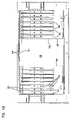
- FIG. 77is a front, top and right side perspective view of an eighth embodiment of a fiber distribution frame according to the present invention, with access panels of an enclosure shown in the open positions;
- FIG. 78is a rear, top, and right side perspective view of the fiber distribution frame of FIG. 77 ;
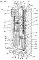
- FIG. 79is a perspective view like FIG. 77 , showing portions of the enclosure removed;
- FIG. 80is a front view of the view of FIG. 79 ;
- FIG. 81is a perspective view like FIG. 78 , showing portions of the enclosure removed;
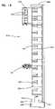
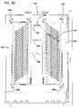
- FIG. 82is a rear view of the view of FIG. 81 ;
- FIG. 83is a top view of the views of FIGS. 79–81 ;
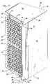
- FIG. 84is a front, top and right side perspective view of a ninth embodiment of a fiber distribution frame similar to the embodiment of FIGS. 77–83 with modified storage spools;
- FIG. 85is a front view of the frame of FIG. 84 , with portions of the enclosure removed.
- FIGS. 1–3one preferred embodiment of a bay or frame 20 is shown for splicing, terminating, and managing fiber optic cables within the frame. Further features of frame 20 are shown in FIGS. 4–13 .
- An upper portion 22 of frame 20defines a termination and storage area.
- a lower portion 24 of frame 20defines a splice area. Cables containing one or more individual optical fibers enter frame 20 typically from an overhead cable environment through a top 26 of frame 20 , or from a raised floor environment at a bottom 28 of frame 20 . If the cables are pre-terminated, the cables extend directly to termination and storage area 22 . If the cables entering frame 20 are not pre-terminated, the cables extend to splice area 24 for splicing to terminated cables.
- the cablesthen extend to termination and storage area 22 .
- termination and storage area 22a plurality of accessible termination locations are provided for the terminated cables and for connecting other cables to the terminated cables, such as patch cords or cables.
- telecommunications equipmentcan be cross-connected between the termination locations through frame 20 .
- Frame 20includes a rack 30 which supports a plurality of termination modules 32 .
- left and right arrays 34 , 36 of termination modules 32are provided.
- Each array 34 , 36 in the illustrated embodimentincludes three individual termination modules 32 a (left side), 32 b (right side).
- Rack 30also supports an inner bay management panel 40 positioned between arrays 34 , 36 of termination modules 32 for organizing and storing excess lengths of patch cables.
- inner bay management panel 40includes a vertical array of individual modules or sections 40 a .
- individual termination modules 32 a , 32 b and individual sections 40 a of inner bay management panel 40all of which are separately mountable to rack 30 , these modules can be added at different times to rack 30 , and replaced, if desired.
- customized frames 20can be provided where other fiber optic management equipment may be utilized in one or more of the areas in rack 30 instead of the six termination modules 32 a , 32 b and the three sections 40 a of inner bay management panel 40 of the illustrated embodiment.
- Rack 30further supports a splice tray assembly 44 , for holding a plurality of splice trays 46 .
- frame 20includes two vertically stacked splice tray assemblies 44 .
- Each splice tray 46includes structure for holding the ends of a plurality of fiber optic cables, and for holding individual splices between the ends of the cables.
- a variety of splice trays 46may be used.
- Example splice traysare shown in commonly assigned U.S. application Ser. No. 09/158,182, filed Sep. 21, 1998, the disclosure of which is hereby incorporated by reference.
- Rack 30further supports a horizontal cable tray 50 positioned between termination and storage area 22 and splice area 24 .
- Horizontal tray 50supports patch cables on a front of frame 20 extending between the left and right arrays 34 , 36 of termination modules 32 and inner bay management panel 40 .
- Tray 50also supports patch cables extending between frame 20 and further frames 20 or other telecommunications equipment in an adjacent area.
- Frame 20preferably includes hingedly mounted upper front doors 52 , 54 , and hingedly mounted lower front doors 56 , 58 for protection of the cables, connectors, adapters and splice trays.
- Upper front doors 52 , 54pivot about vertical axes.
- Lower front doors 56 , 58pivot about horizontal axes.
- the doorspreferably include one or more latches 59 to retain them in the closed positions.
- Rack 30further supports two vertical cable guides 60 , 62 , one on each side of rack 30 , for use in managing and protecting patch cables adjacent to a front of frame 20 .
- Cable guides 60 , 62include a plurality of spaced-apart fingers 65 which permit cable access to an interior of each of cable guides 60 , 62 through a vertical side of each guide.
- each cable guide 60 , 62also includes hinge plates 64 for forming a portion of the hinge for upper front doors 52 , 54 .
- Each cable guide 60 , 62is preferably made in segments, as part of the modular design of frame 20 .
- components making up frame 20are preferably separate components held together by fasteners.
- termination modules 32 , inner bay management panel 40 , splice tray assemblies 44 , cable tray 50 , and cable guides 60 , 62are separate from rack 30 .
- Frame 20defines various access openings to permit cables to enter frame 20 .
- a center opening 66allows cables to enter frame 20 from a raised floor environment.
- Central passage 68allows the cables to pass to the individual splice trays 46 .
- Ties 69( FIGS. 11 and 12 ) are provided to securely tie the incoming cables to frame 20 .
- a central opening 70 in cable tray 50links splice area 24 to termination and storage area 22 .
- access openingsare provided by a rear central opening 72 or two top openings 74 , 76 , one in each top termination module 32 . For pre-terminated cables, the cables can be passed directly through top openings 74 , 76 for termination in the termination modules 32 .
- rear opening 72opens into a rear vertical passage 78 which extends down to splice area 24 , and ties 69 , for splicing to the termination cables at splice trays 46 .
- each section 40 a of inner bay management panel 40includes a center section 80 , two forwardly extending opposed sides 82 , 84 , and one or more vertically spaced central spools 86 forwardly extending from center section 80 .
- Spools 86provide for storage of excess cable lengths for patch cables, such as the patch cables extending between left and right arrays 34 , 36 of termination modules 32 .
- each section 40 aincludes two spools 86 , such that when only one section is provided, cable storage capability is provided.
- each splice tray assembly 44includes a main horizontal support 90 , a main back support 91 , a plurality of divider walls 92 , and plurality of spool cradles or supports 94 , for supporting each of splice trays 46 having a round outer perimeter.
- Divider walls 92extend vertically in the illustrated embodiment.
- Main horizontal support 90has an open middle 90 a for cable passage.
- a cable guide finger 96 , and a cable tie 98are provided to securely retain the cables to frame 20 .
- divider walls 92extend vertically. In other embodiments, the divider walls can be angled with respect to the vertical, or even horizontal. While each splice tray assembly 44 is shown as part of frame 20 , the splice trays could be stored separate from frame 20 , if desired.
- horizontal cable tray 50includes a main horizontal portion 99 including central opening 70 , two opposed and upwardly extending curved cable guides 101 on each side of central opening 70 , and a center cover 102 over central opening 70 .
- Curved guides 101protect cables extending from splice area 24 to termination and storage area 22 .
- Center cover 102prevents stored patch cables from hanging down from inner bay management panel 40 into splice area 24 .
- Cut outs 104 on each end of horizontal tray 50can be filled in with horizontal supports for supporting cables extending horizontally, or downwardly curved supports, if cables are directed downwardly from frame 20 .
- Horizontal cable tray 50also includes a front wall 105 , and a rear wall 106 extending from main horizontal portion 99 .
- each termination module 32includes a top 110 , a bottom 112 , opposed sides 114 , 116 , and a rear 118 .
- the illustrated module 32is from right array 36 .
- each of termination modules 32 a , 32 bare identical, but positioned in a flipped orientation. Therefore, top 110 and bottom 112 would be in the reversed orientation for the left array 34 of modules 32 .
- Each termination module 32defines an open front 120 preferably closed off by a first smaller door 122 and a second larger door 124 , both of which are hingedly mounted to a remainder of termination module 32 about vertical axes.
- First door 122defines a cable access door, especially useful for allowing cables to enter the termination module 32 and for positioning cables passing between locations on frame 20 , such as cable extending between splice area 24 , and an upper termination module 32 positioned above the particular termination module 32 .
- Cable access door 122is rotatably mounted to side 114 by a hinge 126 .
- Second door 124defines a main panel 124 and is rotatably mounted to side 116 by a second hinge 128 .
- Main panel 124includes a plurality of rows 130 of openings 132 each sized for holding an adapter 134 .
- Adapters 134each include at least two aligned openings, one on a front side 134 a , and the other on a rear side 134 b for holding two connectors 142 to optically connect the connectors and the cables connected to the connectors.
- Various adapters 134can be utilized including an adapter of the type shown in U.S. Pat. No. 5,317,663, constructed so as to have the commonly known SC configuration for receiving an SC connector on each end.
- main panel 124includes six upper rows 130 of eight openings each, and six lower rows 130 of eight openings each. If desired, less than eight of the openings can be utilized for a given application.
- adapters 134snap mount to main panel 124 with a clip 135 .
- Designation strips(not shown) can be provided to label each of openings 132 .
- Rear connectors 142 bare connected to the cables entering frame 20 from the telecommunications equipment.
- a rear 140 of main panel 124is primarily utilized as a semi-permanent connection between the connectors 142 b and adapters 134 .
- a front 138 of main panel 124defines a plurality of accessible termination locations which can be connected between each other with patch cables and connectors 142 a , so as to cross-connect the telecommunications equipment.
- Main panel 124includes an angled side panel 143 .
- Side panel 143includes a vertical array of clips 144 adjacent each row 130 of openings 132 .
- Clips 144rotate with main panel 124 and side panel 143 .
- Each clip 144holds the cables from each connector 142 disposed in each row. From clips 144 , the cables extend through a side access of each cable guide 60 , 62 .
- Clips 144help retain and protect the cables as main panel 124 is rotated. Without clips 144 , rotation of main panel 124 may excessively pull or push on the portions of the cables positioned within cable guides 60 , 62 .
- Main panel 124further includes upper and lower hinge plates 146 , 148 .
- a top plate 150 and a bottom plate 152define top 110 and bottom 112 of termination module 32 and each includes a hinge plate portion 154 , 156 which cooperate with hinge plates 146 , 148 to rotatably mount main panel 124 to top and bottom plates 150 , 152 .
- Each of hinge plate portions 154 , 156include a stop 158 , 160 to limit rotation of main panel 124 .
- Main panel 124is disposed at an angle to a vertical plane extending parallel to a front and a rear of frame 20 . Such angling permits increased density over adapters 134 arranged with the longitudinal axes transverse to the front and rear planes. Also, cable management is facilitated by the angling of the cables toward cable guides 60 , 62 . For right array 36 of modules 32 , main panels 124 are angled toward the right side of rack 30 . For left array 34 of modules 32 , main panels 124 are angled toward the left side of rack 30 .
- each latch 162engages a tab 164 extending from top and bottom plates 150 , 152 .
- Cable access door 122is also maintained in the closed position shown in FIGS. 4 and 5 by a second latch 166 which engages an edge 168 of main panel 124 . Cable access door 122 also overlaps edge 168 .
- Both top and bottom plates 150 , 152include cable passages 170 , to permit vertical passing of cables into, and through termination module 32 , if desired.
- a cable clamp 182securely holds a cable entering termination module 32 .
- a lower tab 181 ahelps maintain the cable in passage 170 .
- Tab 181 aalso maintains other cables passing through module 32 in passage 170 .
- An intermediate tab 181 c and an upper tab 181 bare also provided to position desired cables in passage 170 .
- the individual fibersare routed through a cable transitional area 171 including various cable guides 186 including tabs, spools, clips, or rings.
- a tie bracket 190can be utilized with or instead of clamp 182 (see FIGS. 9 and 10 ) to tie down cable entering termination module 32 .
- a rear tray 192is positioned in a central location on main panel 124 projecting horizontally and rearwardly.
- Rear tray 192includes a plurality of horizontal cable rings 194 .
- a curved edge 196helps prevent rear tray 192 from catching on cables positioned within an interior of termination module 132 , either in vertical cable passage 170 , or in cable transitional area 171 .
- an example cable 184 containing multiple fibersenters termination module 32 through bottom plate 152 in passage 170 .
- Clamp 182holds cable 184 .
- a first fiber 184 aextends around upper spool or guides 186 a , past intermediate guides 186 b , and around lower spool or guides 186 c , around lower corner guide 186 d to lower ring 188 b , through horizontal ring 194 to one of the upper locations on main panel 124 .
- Second example fiber 184 bextends around upper guides 186 a , past intermediate guides 186 b , around lower guides 186 c , back upward past intermediate guides 186 b , around upper guides 186 a , around upper corner guide 186 e and through upper ring 188 a . From upper ring 188 a , second fiber 184 b passes through horizontal ring 194 to a lower location on main panel 124 . All of adapters 134 on main panel 124 can be connected to individual fibers entering termination module 32 . For additional termination modules mounted to frame 20 , mounted above termination module 32 , the cables will pass through the lower termination modules to reach the upper termination modules in passage 170 . In use, left array 34 of frame 20 may be utilized to terminate cables entering the building.
- Right array 36may be utilized to terminate cables connected to various telecommunications equipment within the building.
- the fronts of each termination module 32are utilized to run patch cables from the left side to the right side to cross-connect the various rear termination locations.
- the patch cablespass beneath inner bay management panel 40 . From each front connector location, the patch cables enter one of cable guide 60 , 62 for vertical management of the patch cables. From a lower end of cable guides 60 , 62 the cables pass horizontally to the other side of frame 20 , the inner bay management panel 40 , or to another frame or other equipment. Excess lengths of cable in the patch cables can be wound around appropriate spools 86 to conveniently store the excess lengths, and to avoid tangling the patch cables together.
- the patch cablesmay run from either the left or the right array 34 , 36 to an adjacent frame, or to other equipment.
- FIGS. 14–24a second preferred embodiment of a frame 220 is shown for splicing, terminating, and managing fiber optic cables within the frame.
- An upper portion 222 of frame 220defines a termination area.
- a lower portion 224 of frame 220defines a splice area.
- Cables containing one or more individual optical fibersenter frame 220 typically from an overhead cable environment through a top 226 of frame 220 , or from a raised floor environment at a bottom 228 of frame 220 . If the cables are pre-terminated, the cables extend directly to termination area 222 . If the cables entering frame 220 are not pre-terminated, the cables extend to splice area 224 for splicing to terminated cables.
- the cablesextend to termination area 222 .
- termination area 222a plurality of accessible termination locations are provided for the terminated cables and for connecting other cables to the terminated cables, such as patch cords or cables.
- Telecommunications equipmentcan be cross-connected between the termination locations through frame 220 .
- Frame 220includes a rack 230 which supports a plurality of termination modules 232 .
- left and right arrays 234 , 236 of termination modules 232are provided.
- Each array 234 , 236 in the illustrated embodimentincludes three individual termination modules 232 a (left side), 232 b (right side).
- Rack 230also supports a cable management panel 240 positioned vertically along one or both arrays 234 , 236 of termination modules 232 for organizing and storing excess lengths of patch cables.
- a cable management panel 240positioned vertically along one or both arrays 234 , 236 of termination modules 232 for organizing and storing excess lengths of patch cables.
- two cable management panels 240are provided. Panels 240 are joined to ends 231 of rack 230 . Additional racks 230 can be mounted to panels 240 as desired, with panels 240 serving as spacers between adjacent racks 230 .
- Each panel 240includes two sections 240 a .
- these modulescan be added at different times to rack 230 , and replaced, if desired.
- customized frames 220can be provided where other fiber optic management equipment can be utilized in one or more of the areas in rack 230 instead of the six termination modules 232 a , 232 b and the two sections 240 a of each cable management panel 240 of the illustrated embodiment.
- Rack 230further supports a splice tray assembly 244 , for holding a plurality of splice trays 46 .
- Frame 220includes two vertical stacks 246 , 248 of splice tray holders. Splice tray 46 as noted above for frame 20 is usable for frame 220 . Alternatively, other splice trays may be used.
- Rack 230further supports a horizontal cable tray 250 positioned below splice area 224 .
- Horizontal cable tray 250supports patch cables on a front of frame 220 extending between the left and right arrays 234 , 236 of termination modules 232 .
- Tray 250also supports patch cables extending between frame 220 and further frames 220 or other telecommunications equipment in an adjacent area.
- Rack 230further supports two vertical cable guides 260 , 262 , one on each side of rack 230 , for use in managing and protecting patch cables adjacent to a front of frame 220 .
- Cable guides 260 , 262include a plurality of spaced-apart fingers 265 which permit cable access to an interior of each cable guide 260 , 262 through a vertical side of each guide.
- Each of cable guides 260 , 262is preferably made in segments 263 , as part of the modular design of frame 220 .
- components making up frame 220are preferably separate components held together by fasteners, to aid in assembly, and versatility in use.
- termination modules 232 , cable management panels 240 , splice tray assembly 244 , cable tray 250 , and cable guides 260 , 262are separate from rack 230 .
- Frame 220defines various access openings to permit cables to enter frame 220 .
- a center opening 266allows cables to enter frame 220 from a raised floor environment.
- Central passage 268allows the cables to pass to the individual splice trays 46 .
- Clamps 267 and ties 269are provided to secure the incoming cables to frame 220 .
- a central passageway 270links splice area 224 to termination area 222 .
- Adjacent to top 226 of frame 220an access opening 272 and cable clamps 275 are provided. For pre-terminated cables, the cables can be passed directly through top opening 272 for termination in the termination modules 232 .
- opening 272opens into a vertical passage 278 which extends down to central passageway 270 to splice area 224 , and ties 269 for splicing to the termination cables at splices trays 46 .
- Cable rings 274are provided to manage the passage of cables in termination area 222 .
- Each cable management panel 240includes a center section 280 , and one or more vertically spaced spools 286 forwardly extending from center section 280 .
- Spools 286provide for storage of excess cable lengths for patch cables, such as the patch cables extending between left and right arrays 234 , 236 of termination modules 232 .
- Each spool 286preferably includes a front flange 287 to aid in cable retention on the spools 286 .
- Splice tray assembly 244includes a main vertical support 290 and a plurality of divider walls 292 extending forwardly.
- the divider walls 292are preferably arranged in two vertical stacks 246 , 248 . Further, the divider walls 292 are preferably angled.
- Splice tray assembly 244is shown for use with cables entering adjacent to top 226 of frame 220 . If cables enter from bottom 228 , it may be advantageous to angle divider walls 292 in an opposite direction, as shown in FIG. 27 for modified frame 520 .
- side lips 294are provided on opposite sides of each divider wall 292 .
- front notches 295are provided to facilitate ease of access to a stored splice tray 46 .
- the angling of dividers 292aids in reducing the horizontal space taken up by splice tray assembly, and allows for sufficient cable pathway spacing to upper pathway 278 .
- Horizontal cable tray 250includes a main horizontal portion 299 , a rear wall 300 , and one or more front walls 302 .
- the front and rear walls 302 , 299help protect and retain patch cables passing through horizontal cable tray 250 .
- each termination module 232includes a top 310 , a bottom 312 , opposed sides 314 , 316 , and a rear 318 .
- Side 314defines a side opening 315 bounded on three sides. Side opening 315 permits cable access to an interior of module 232 .
- the illustrated module 232is from right array 236 .
- each of termination modules 232 a , 232 bare identical but positioned in a flipped orientation. Therefore, top 310 and bottom 312 would be in a reversed orientation for the left array 234 of modules 232 .
- Each termination module 232defines an open front 320 preferably closed off by door or main panel 324 which is hingedly mounted to a main housing 322 .
- Main panel 324is rotatably mounted adjacent to side 316 by a hinge 328 .
- Main panel 324includes a plurality of openings 332 (see FIGS. 14–16 ) each sized for holding one or more adapters 134 . Openings 332 are configured as elongated slots.
- angled retainers 336are provided to facilitate mounting of adapters 134 .
- various adapters 134can be utilized including an SC type.
- main panel 324includes six upper openings 332 , and six lower openings 332 , each holding eight angled retainers 336 and adapters 134 .
- individual openingscan be provided for each adapter as noted above in the embodiment of FIGS. 1–13 .
- rear connectors 142 bare connected to the cables entering frame 220 from the telecommunications equipment.
- a rear 340 of main panel 324is primarily utilized as a semi-permanent connection between the connectors 142 b and adapters 134 .
- a front 338 of main panel 324defines a plurality of accessible termination locations which can be connected between each other with patch cables and connectors 142 a so as to cross-connect the telecommunications equipment.
- Main panel 324includes an angled side panel 343 including a vertical array of clips 344 adjacent each row of adapters 134 . Clips 344 rotate with main panel 324 and side panel 343 . Each clip 344 holds the cables from each connector 142 a disposed in each row.
- each cable guide 260 , 262From clips 344 , the cables extend through a side access of each cable guide 260 , 262 .
- Clips 344help retain and protect the cables as main panel 324 is rotated. Without clips 344 , rotation of main panel 324 may excessively pull or push on the portions of the cables positioned within cable guides 260 , 262 .
- Main panel 324further includes upper and lower hinge plates 346 , 348 .
- a top plate 350 and a bottom plate 352define top 310 and bottom 312 of termination module 232 and each includes a hinge plate portion 354 , 356 which cooperate with hinge plates 346 , 348 to rotatably mount main panel 324 to top and bottom plates 350 , 352 .
- Each of hinge plate portions 354 , 356includes a stop 358 , 360 to limit rotation of main panel 324 .
- Main panel 324is disposed at an angle to a vertical plane extending parallel to a front and a rear of frame 220 . Such angling permits increased density over adapters arranged with the longitudinal axes transverse to the front and rear planes. Also, cable management is facilitated by the angling of the cables toward cable guides 260 , 262 . For right array 236 of modules 232 , main panels 324 are angled toward the opposite side of rack 230 . Similarly, for left array 234 of modules 232 , main panels 324 are angled toward the right side of rack 230 . Use of the angled retainers 362 permits angling back of the cables toward the respective right and left sides of rack 230 .
- latches 362are provided, similar to latches 162 noted above. Each latch 362 engages a tab 364 extending from top and bottom plates 350 , 352 .
- Cable clamps 382securely hold the cable or cables entering termination module 232 at side opening 315 through side 314 .
- Lower clamps 382 aare used for cables entering termination module 232 from above.
- Upper clamps 382 bare used for cable entering termination module 232 from below.
- all of the clamps 382are positioned at an angle.
- Clamps 382are preferably positioned on mounting flanges 383 . From clamps 382 , the individual fibers are routed through various cable guides 386 including tabs, spools, clips, or rings.
- a tie bracket 390can be utilized with or instead of clamps 382 to tie down cable entering termination module 332 .
- a rear tray 392is positioned in a central location on main panel 324 projecting horizontally and rearwardly.
- Rear tray 392includes one or more horizontal cable rings 394 .
- a vertical lip 395extends rearwardly from the free edge of main panel 324 to protect the cables and the connectors.
- example cablesenter termination module 232 through side opening 315 .
- Clamp 382holds example first and second fibers 384 a , 384 b .
- First fiber 384 aextends around lower spool or guide 386 a to an upper spool or guide 386 b around an upper corner guide 386 c to upper ring 388 b , through horizontal ring 394 to one of the lower locations on main panel 324 .
- Second example fiber 384 bextends from lower guide 386 a , to lower corner guide 386 d , and through lower ring 388 a . From lower ring 388 a , second fiber 384 b passes through horizontal ring 394 to an upper location on main panel 324 .
- Frame 220is used in a similar manner as frame 20 where the left and right arrays 234 , 236 may be utilized to terminate cables entering the building, and cables connected to various telecommunications within the building. Frame 220 may be utilized to run patch cables in order to cross-connect the various rear termination locations. The patch cables pass beneath splice area 224 . From each front connection location, the patch cables enter one of cable guides 260 , 262 for vertical management of the patch cables. From a lower end of cable guides 260 , 262 , the cables pass horizontally to the other side of frame 220 , or to another frame or other equipment.
- patch cablescan be wound around appropriate spools 286 in one of cable management panels 240 to conveniently store the excess lengths, and to avoid tangling the patch cables together.
- the patch cablesmay run from either the left or the right array 234 , 236 to an adjacent frame, or to other equipment.
- a frame 420is shown which is similar to frame 220 for the features of the rack 230 , termination modules 232 , splice tray assembly 244 , cable management panels 240 , and guides 260 , 262 .
- Frame 420includes adjustable cable rings 474 in termination area 222 .
- Ring 474includes outer arms 475 and inner moveable arms 476 . The location and spacing of arms 476 can be selected depending on the location and amount of cable to be held by rings 474 .
- a cable ring 474is shown in greater detail in FIGS. 28 and 29 .
- Inner arms 476are held by fasteners 477 to a connecting section 478 of outer arms 475 .
- Inner arms 476define an inner chamber 480 for cables entering frame 420 .
- the serrations 482can be used to secure an o-ring or other tie to secure the cables in chamber 480 .
- outside of chamber 480 in area 484other cables can be positioned, such as cables from the splice area 244 extending to the termination area 224 .
- frame 420includes a lower opening 480 so as to allow cables to pass to a rear side of frame 420 , for passing the cable to a second frame mounted back-to-back with frame 420 , or to connect to other telecommunications equipment.
- Frame 520 of FIG. 27includes splice tray assembly 244 mounted in an inverse position so that the dividers 292 angle downwardly in a direction toward the center of frame 520 .
- the arrangement of FIG. 27is useful for managing cables entering from bottom 528 which are terminated at splice tray assembly 244 .
- assembly 244is identical in frames 420 , 520 but selectively mounted in the desired orientation.
- FIGS. 30–37a fourth preferred embodiment of a frame 620 is shown for splicing, terminating, and managing fiber optic cables within the frame.
- An upper portion 622 of frame 620defines a termination area.
- a lower portion 624 of frame 620defines a splice area, as for example described above for the embodiments shown in FIGS. 1–29 .
- Cables containing one or more individual optical fibersenter frame 620 typically from an overhead cable environment through a top 626 of frame 620 , or from a raised floor environment at a bottom 628 of frame 620 . If the cables are pre-terminated, the cables extend directly to termination area 622 . If the cables entering frame 620 are not pre-terminated, the cables extend to splice area 624 for splicing to terminated cables.
- Frame 620includes a rack 630 which supports a plurality of termination modules 632 .
- left and right arrays of termination modules 632are provided.
- FIGS. 30–32only the right array 636 is shown.
- Each array in the illustrated embodimentincludes three individual termination modules 632 b (only 2 are shown).
- Frame 620is used to cross-connect telecommunications equipment through the termination locations provided by the frame.
- Frame 620also includes a cable management panel (not shown), as described above, and a horizontal cable tray 650 positioned below splice area 624 .
- Rack 630further supports two vertical cable guides 660 , 662 , one on each side of rack 630 , for use in managing and protecting patch cables adjacent to a front of frame 620 .
- Cable guides 660 , 662include a plurality of fingers 664 , including one angled finger 665 .
- Each of cable guides 660 , 662is preferably made in segments 663 , as part of the modular design of frame 620 .
- Each segment 663includes a base section 670 , a side section 672 , and a hinge 674 for hingedly mounting front doors (not shown) to rack 630 .
- Fingers 664 , 665all extend from side section 672 .
- components making up frame 620are preferably separate components held together by fasteners, to aid in assembly, and versatility in use.
- termination modules 632 , and cable guides 660 , 662are separate from rack 630 .
- each termination module 632includes a top 710 , a bottom 712 , opposed sides 714 , 716 , and a rear 718 .
- Side 714defines a side opening 715 bounded on three sides.
- Side opening 715permits cable access to an interior of module 632 .
- the illustrated module in FIGS. 33–37is from right array 636 .
- termination module 632 from right array 636is not identical to the termination modules for use in the left array, as will be seen from the following discussion.
- Each termination module 632defines an open front 720 preferably closed off by door or main panel 724 which is hingedly mounted to main housing 722 , in a similar manner as module 232 noted above.
- Main panel 724is constructed in a similar manner as main panel 324 noted above with respect to the mounting of adapters 134 .
- the main panels 724are shown fully loaded with adapters 134 .
- main panel 724includes a plurality of guides or extensions 744 , one adjacent to each row of adapters 134 .
- Guides 744extend from side panel 743 .
- Guides 744rotate with main panel 724 and side panel 743 .
- Each guide 744holds the cables from each connector 142 a disposed in each row. From guides 744 , the cables extend through a side access of the closest vertical cable guide 660 , 662 .
- Guides 744help retain and protect the cables as main panel 724 is rotated. Without guides 744 , rotation of main panel 724 may excessively pull or push on the portions of the cables positioned within vertical cable guides 660 , 662 .
- Guides 744are preferably formed as extensions of planar side panel 743 .
- Sheet metalis a convenient material for making main panel 724 and side panel 743 , as well as guides 744 .
- Each guide 744includes a main extension 746 , with an angled tab 748 , angled toward the respective vertical cable guide 660 , 662 . Extending vertically on opposite sides of tab 748 are first and second fingers 750 , 752 .
- a slot 754is formed between one finger 750 , 752 of one guide 744 and an opposite finger 752 , 750 of an adjacent guide 744 above or below the respective guide. Slot 754 is sized for receipt of cables, such as during installation or removal of the cables.
- slot 754is at an angle to the horizontal, to help limit each cable from falling out of guides 744 during movement of other cables, or movement of main panel 724 .
- An edge protector 756is snapped over main extension 746 to protect the cables from possible damage from the sharper edges of main extension 746 , such as occurs if sheet metal is used.
- main panel 724is hingedly mounted top 710 and bottom 712 of termination module 632 . Further, main panel 724 is disposed at an angle to a vertical plane extending parallel to a front and a rear of frame 620 . Further, main panel 724 includes the use of angled retainers 362 as noted above. To maintain main panel 724 in the closed position, two vertically operated latches 762 are provided, similar to the latches noted above which operate horizontally.
- Cable clamps 782securely hold the cable or cables entering termination module 632 at side opening 715 through side 714 .
- Lower clamps 782 aare used for cables entering termination module 632 from below.
- Upper clamps 782 bare used for cables entering termination module 632 from above.
- all of clamps 782are positioned at an angle.
- Clamps 782are preferably positioned on mounting flanges 783 . From clamp 782 , the individual fibers are routed through various cable guides 786 including tabs, spools, clips, or rings.
- a tie bracketcan be utilized with or instead of the clamps to tie down cable entering termination module 632 .
- a rear tray 792is positioned along a lower edge of main panel 724 projecting horizontally and rearwardly.
- Rear tray 792includes one or more horizontal cable rings 794 .
- a vertical lip 795extends rearwardly from the free edge of main panel 724 to protect the cables and the connectors.
- example cablesenter termination module 632 through side opening 715 .
- Clamp 782holds example first and second fibers 784 a , 784 b . Both fibers extend around lower spool or guide 786 a to an upper spool or guide 786 b through an upper ring 786 c , and through horizontal ring 794 to one of the connection locations on main panel 724 .
- a rear cover 800is supplied for protecting the cables adjacent to the connection locations on a rear side of main panel 724 .
- a termination module 632 ′ from the left array of frame 620is shown.
- the module 632 ′ of FIG. 37is a mirror image of the module 632 of FIG. 34 .
- Cover 800mounts to rear tray 792 w/with a tab 802 over lip 796 of tray 792 .
- a leaf spring 804fits into notch 798 .
- Two top tabs 806 , 808engage a top of panel 724 to further secure cover 800 .
- Frame 920can be used with splice tray assemblies 44 , 224 , and termination modules 32 , 232 , 632 , with hinged doors as noted above.
- Frame 920includes termination modules 940 which provide the termination function as for modules 32 , 232 , 632 , and further include couplers used for monitoring and/or testing fiber optic signal transmission.
- an upper portion 922 of frame 920defines a termination area.
- a lower portion 924 of frame 920defines a secondary area, such as for splicing as described above for the embodiments of FIGS. 1–37 .
- the secondary areacan include additional termination areas by populating frame 920 with similar terminations as in upper portion 922 .
- lower portion 924can provide cable storage locations, such as including spools.
- Cables containing one or more individual optical fibers enter frame 920typically from an overhead cable environment through a top 926 of frame 920 , or from a raised floor environment at a bottom 928 of frame 920 . If the cables are pre-terminated, the cables extend directly to termination area 922 and into central cable passageway 970 . If the cables entering frame 920 are not pre-terminated, the cables extend to lower portion 924 for splicing to terminated cables and then through passage 979 to termination area 922 . Cables in central passageway 970 enter the termination modules 940 through side access openings as will be described below.
- Frame 920includes a rack 930 which supports a plurality of termination modules 940 along right side 934 .
- termination modules 632are termination modules 632 , as described above for the embodiment of FIGS. 30–37 . If desired, one or more termination modules 940 can also populate left side 932 .
- Frame 920is used to cross-connect telecommunications equipment through the termination locations provided by the frame. Frame 920 is also used to monitor, test or provide other functions with respect to the signals passing through termination modules 940 , such as splitting, combining, etc. Frame 920 may also include a cable management panel (not shown) as described above along the right or left sides, and a horizontal cable tray 950 at or below lower portion 924 .
- Rack 930further supports two vertical cable guides 960 , 962 similar to guides 660 , 662 noted above, for use in managing and protecting patch cables adjacent to a front of frame 920 .
- components making up frame 920are preferably separate components held together by fasteners, to aid in assembly, and versatility in use.
- termination modules 632 , 940 and cable guides 960 , 962are separate from rack 930 .
- Modules 632 , 940mount to rear panel 942 of rack 930 .
- each termination module 940includes a top 1010 , a bottom 1012 , opposed sides 1014 , 1016 , and a rear 1018 .
- Side 1014defines a side opening 1015 bounded on four sides.
- Side opening 1015permits cable access and user access to an interior of termination module 940 from central passageway 970 .
- the illustrated module in FIGS. 41–49is from the right array 936 .
- Termination module 940can be flipped so as to create a left array, somewhat similar to termination modules 232 a , 232 b noted above. Alternatively, right and left modules can be designed for use on only one side, as for modules 632 .
- Each termination module 940defines an open front 1020 through a main panel section 1024 which receives individual connector modules or units 1200 , such as further illustrated in FIGS. 50–58 .
- main panel 724defined the various termination locations.
- the front faces 1202 of each connector module 1200cooperate with each other in termination module 940 to create the array of termination locations of a main panel 1025 of termination module 940 .
- Each connector module 1200allows for the mounting of front adapters 134 in one or more openings 1203 associated with each connector module 1200 .
- the termination modules 940 of FIGS. 38 and 39are shown without the adapters 134 in openings 1203 . Any number of openings can be provided, such as one for all the adapters of each module 1200 , or more openings, such as one per adapter, or three (2 adapters 134 per opening) in the illustrated embodiment.
- the main or front panel section 1025 of termination module 940defines open front 1020 .
- a vertical array of guides 1044are provided for protecting and retaining the cables, one guide adjacent to each row of adapters 134 .
- Side 1026extends generally parallel to side 1016 of termination module 940 .
- one guide 1044is provided per connector module 1200 .
- Each guide 1044holds the cables from each front connector 142 a disposed in each row. From guides 1044 , the cables extend through a side access of the closest vertical cable guide 660 , 662 .
- connector module 1200is slid into position in termination module 940 and held in a desired vertical position in module 940 .
- An opposite side 1028 of main panel section 1025includes a plurality of guides or notches 1030 for slideably receiving a guide or side flange 1228 of connector module 1200 .
- Side 1028further includes openings 1032 for receiving a fastener or latch 1224 of connector module 1200 .
- Opposite side 1026includes notches 1034 for receiving a similar fastener 1226 on an opposite side of connector module 1200 .
- Termination module 940includes connector module holders disposed in the interior.
- interior horizontal shelves 1050support and hold the individual connector modules 1200 .
- Shelves 1050are partial planar shelves, not filling the entire inside of termination module 940 . This allows front access through open front 1020 for mounting termination module 940 to frame 920 through rear fastener holes 1052 , and rear alignment holes 1054 through rear 1018 . Alignment holes 1054 assist an installer by receiving pegs associated with rear panel 942 of rack 930 , prior to the insertion of fasteners through fastener holes 1052 .
- Side 1016 and rear 1018each include a column of horizontal slots 1072 , 1070 for supporting an edge of each shelf 1050 .
- Shelves 1050further include tabs 1074 , 1076 for receiving a fastener for mounting to fastener holes 1078 , 1080 in rear 1018 and side 1016 to fasten each shelf 1050 in place in termination module 940 .
- Termination module 940further includes one or more cable supports 1056 at side opening 1015 .
- Cable supports 1056protect cables from sharp bends of from contacting any nearby sharp edges.
- Cable supports 1056include a longitudinal section 1058 extending from side 1057 , a bend section 1060 , and an edge protector 1062 .
- Top and bottom supports 1056 a, bare turned 90° relative to a horizontal longitudinal axis and help protect entering cables from damage by edge 1017 .
- connector module 1200includes a housing 1201 including front 1202 , and a rear 1204 .
- Front 1202 and rear 1204are generally planar.
- Major sides 1206 , 1208are parallel to one another and spaced-apart to define an interior which cooperates with spaced-apart minor sides 1210 , 1212 to house fiber optic circuitry.
- Minor sides 1210 , 1212are generally parallel to each other.
- Housing 1201further defines a rear notch 1216 extending from minor side 1210 to rear 1204 .
- end flanges 1220 , 1222are provided, for supporting fasteners, locks or latches 1224 , 1226 .
- Flange 1222is angled relative to the plane defined by front 1202 .
- Front 1202 of connector moduleincludes a plurality of adapters 134 for receiving connectors 142 a of patch cables. Angled retainers 362 hold each adapter 134 so its longitudinal axis is at a non-transverse angle to the plane defined by front 1202 .
- side segment 1230 of housing 1201provides a mounting surface for rear adapters 134 a .
- Each rear adapter 134 areceives a rear connector 142 b for the cables from passageway 970 .
- Rear retainers 1240hold each rear adapter 134 a to housing 1201 . Rear snap in retainers 1240 allow convenient assembly, and removal if necessary.
- Adapters 134 , 134 acan be SC type (as shown), FC type, ST type or other.
- Side flange 1228extends from major side 1206 . If connector module 1200 is used on left side 932 of frame 920 for a termination module 940 on the left side, connector module 1200 is flipped over to have its front angle toward the right side 934 of frame 920 . An angled side segment 1231 connects side 1210 to side segment 1230 .
- couplers 1242Disposed within housing 1201 of connector module 1200 is one or more couplers 1242 , such as splitters, combiners, wave division multiplexers, etc. for connecting between rear adapters 134 and front adapters 134 .
- 1 ⁇ 2 splittersare provided for couplers 1242 .
- Rear internal connectors 1244 and fibers 1246connect to couplers 1242 .
- From couplers 1242further fibers 1248 connect to further internal front connectors 1250 at front adapters 134 .
- Connectors 1244 , 1250are similar connectors to connectors 142 a, b .
- a coupler holder 1260may be provided, as desired to secure couplers 1242 in place.
- Fiber management guides 1262 , 1264may be provided as appropriate to secure fibers 1246 , 1248 in position.
- fibers 1246follow an S-path, followed by a loop-path before connecting to couplers 1242
- fibers 1248follow a loop-path.
- connectors 142 b extending from rear adapters 134 a along an exterior of housing 1201are protected and do not protrude into central passageway 970 of frame 920 . Further, the notch 1216 also allows for a greater front panel surface area, as well as a greater volume within the housing 1201 for routing of fibers from the rear adapters 134 a to the couplers 1242 , and then to the front adapters 134 .
- FIGS. 59–61a sixth preferred embodiment of a frame 1320 is shown with three termination modules 632 on left side, one termination module 940 , a column of splice trays 244 with divider walls 292 , and a column of cable management spools 86 and spaced-apart sides 82 , 84 . Further cable guides 1234 and walls 1236 of splice trays 244 are added to assist with cable management in vertical cable guides 960 , 962 .
- FIGS. 59–61further illustrate the variety and versatility of the various frames of the present invention.
- Termination module 1440includes room for less connector modules 1200 (10 instead of 12) over termination module 940 . Only upper and lower guides 1056 a, b are provided, allowing greater access to rear adapters 134 a and rear connectors 142 b . Also, module 1440 cannot be flipped to the left side of frame 1420 . A mirror image of module 1440 with appropriately configured notches 1030 to receive flipped connector modules 1200 would have to be constructed, so as to fit on the left side of frame 1420 .
- FIGS. 66–76modified preferred embodiments for a termination module 1540 and connector modules 1600 , 1700 are shown.
- a vertical array of longitudinal guides or rails 1560is provided instead of planar shelves 1050 as in termination modules 940 , 1440 .
- Rails 1560provide additional interior room within termination module 1540 over shelves 1050 .
- Connector module 1660is similar in many respects to connector module 1200 .
- Side flange 1228is received in one of notches 1030 in termination module 1540 .
- a second side flange 1620 from major side 1618is provided to slideably cooperate with one of rails 1560 , to mount and hold connector module 1600 in termination module 1540 .
- connector modules of different heightscan be conveniently used, if desired.
- a modified connector module 1700 of FIGS. 73–76can be utilized in termination module 1540 wherein two rows of openings 1703 are provided on front face 1702 .
- Side flange 1720is received in one of rails 1560 ( 1560 a in FIG. 66 ).
- the connector module 1700having a double height, or triple, quadruple, etc., not all of rails 1560 are utilized. However, because of the low profile provided by rails 1560 , the multi-heighted connector modules 1700 are easily utilized in termination module 1540 .
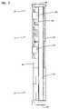
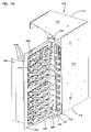
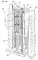
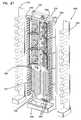
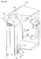
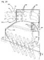
- Frame 1820has particular application as an outside plant enclosure for use in cross-connecting outside plant cables.
- Frame 1820includes an enclosure 1822 which fits over and protects the outside plant cables extending upwardly from the ground into enclosure 1822 .
- Moveable panels or doors 1824 , 1826allow access to an interior of enclosure 1822 .
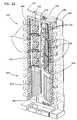
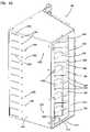
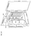
- Frame 1820includes a rack 1830 which supports vertical cable guides 1840 , splice tray holders 1850 , termination modules 1832 , and various cable management devices.
- Frame 1820includes termination module 1832 with pivoting front panels 1834 , which hold the fiber optic terminations similar to termination modules 632 described above.
- Other termination modulessuch as modules 32 , 232 , 940 , 1440 , and 1540 described above may be used.
- the termination modules 1832can include pass-through connections, or connector modules including various fiber optic components, as desired.
- Termination modules 1832communicate with vertical cable guides 1840 for patch cords linking the front termination locations between the left 1836 and right 1838 of rack 1830 .
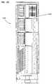
- Termination modules 1832are positioned on a front side 1842 of rack 1830 .
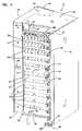
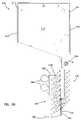
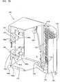
- Positioned on a rear side 1844 of rack 1830are splice tray holders 1850 .
- a plurality of angled divider walls 1852 or other wallsdefine the individual splice tray holders, for holding individual splice trays 1854 , in a similar manner as noted above.
- a cable pass-through 1870links the front and rear sides of rack 1830 .
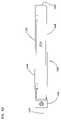
- the outside plant cablesare clamped to rack 1830 at clamps 1880 .
- the cablesare positioned in one of left or right outer passages 1882 or 1884 and then enter rear central passage 1886 for splicing to cables at trays 1854 .
- From trays 1854the cables pass through pass-through 1870 to termination modules 1832 .
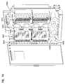
- Lower radius limiters 1888 and upper radius limiters 1890define outer passages 1882 , 1884 .
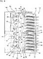
- Rings 1892 in central passage 1886define cable pathways and cable tie locations for the cables extending to the individual splice trays, and from the splice trays to pass-through 1870 .
- Rack 1830also includes storage radius limiters 1894 which are utilized for storage of cable at the rear side 1844 of rack 1830 . In that situation, the cables are wound around radius limiters 1888 , 1890 , 1894 through outer passages 1882 , 1884 .
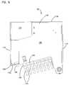
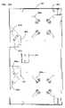
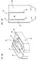
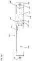
- Center spools 1900assist with cable management of the cables linking splice trays 1854 to termination modules 1832 .
- Patch cordsextend from the front of termination modules 1832 into the nearest vertical cable guide 1840 and down to lower cable area 1898 .
- Lower spools 1906assist with cable management of the patch cables extending across lower area 1898 . Excess lengths of the patch cords can be stored on center spools 1900 .
- center spools 1900include an end plate 1902 and a mid plate 1904 .
- Plates 1902 , 1904divide each spool 1900 into first and second areas 1903 , 1905 .
- First area 1903is for guiding the cables, such as pigtails, from the rear side 1844 of the frame, before entry into one of modules 1832 .
- Second area 1905is for any patch cords wound around spools 1900 .
- Lower spools 1906also include a cable retention end plate 1908 .
- Frame 1820has particular application in the outside plant situation. Separate access is provided for splicing and terminating, to allow field technicians to access only the required components, and further to help minimize fiber movement.
- Frame 2020 of FIGS. 84 and 85includes modified center spools 2100 including modified midplates 2104 .
- Midplates 2104are more circular in perimeter with projecting fingers 2106 .
- Holes 2108 on each finger 2106can be used to tie the cables in position to assist with cable management.
Landscapes
- Physics & Mathematics (AREA)
- Engineering & Computer Science (AREA)
- Computer Networks & Wireless Communication (AREA)
- General Physics & Mathematics (AREA)
- Optics & Photonics (AREA)
- Light Guides In General And Applications Therefor (AREA)
- Mechanical Coupling Of Light Guides (AREA)
Abstract
Description
Claims (38)
Priority Applications (7)
| Application Number | Priority Date | Filing Date | Title |
|---|---|---|---|
| US11/401,680US7333707B2 (en) | 1999-03-01 | 2006-04-10 | Optical fiber distribution frame with outside plant enclosure |
| US12/070,541US7805043B2 (en) | 1999-03-01 | 2008-02-19 | Optical fiber distribution frame with outside plant enclosure |
| US12/806,239US8019192B2 (en) | 1999-03-01 | 2010-08-05 | Optical fiber distribution frame with outside plant enclosure |
| US13/198,218US8768134B2 (en) | 1999-03-01 | 2011-08-04 | Optical fiber distribution frame with outside plant enclosure |
| US14/173,025US9429728B2 (en) | 1999-03-01 | 2014-02-05 | Optical fiber distribution frame with outside plant enclosure |
| US15/224,794US9810868B2 (en) | 1999-03-01 | 2016-08-01 | Optical fiber distribution frame with outside plant enclosure |
| US15/707,217US10067309B2 (en) | 1999-03-01 | 2017-09-18 | Optical fiber distribution frame with outside plant enclosure |
Applications Claiming Priority (9)
| Application Number | Priority Date | Filing Date | Title |
|---|---|---|---|
| US25986099A | 1999-03-01 | 1999-03-01 | |
| US32558499A | 1999-06-03 | 1999-06-03 | |
| US09/412,674US6424781B1 (en) | 1999-03-01 | 1999-10-05 | Optical fiber distribution frame with pivoting connector panels |
| US09/563,210US6535682B1 (en) | 1999-03-01 | 2000-05-02 | Optical fiber distribution frame with connector modules |
| US09/577,779US6556763B1 (en) | 1999-03-01 | 2000-05-24 | Optical fiber distribution frame with connector modules |
| US09/716,627US6760531B1 (en) | 1999-03-01 | 2000-11-20 | Optical fiber distribution frame with outside plant enclosure |
| US10/759,680US7149398B2 (en) | 1999-03-01 | 2004-01-19 | Optical fiber distribution frame with outside plant enclosure |
| US10/942,734US7139461B2 (en) | 1999-03-01 | 2004-09-15 | Optical fiber distribution frame with outside plant enclosure |
| US11/401,680US7333707B2 (en) | 1999-03-01 | 2006-04-10 | Optical fiber distribution frame with outside plant enclosure |
Related Parent Applications (1)
| Application Number | Title | Priority Date | Filing Date |
|---|---|---|---|
| US10/942,734ContinuationUS7139461B2 (en) | 1999-03-01 | 2004-09-15 | Optical fiber distribution frame with outside plant enclosure |
Related Child Applications (1)
| Application Number | Title | Priority Date | Filing Date |
|---|---|---|---|
| US12/070,541ContinuationUS7805043B2 (en) | 1999-03-01 | 2008-02-19 | Optical fiber distribution frame with outside plant enclosure |
Publications (2)
| Publication Number | Publication Date |
|---|---|
| US20060193590A1 US20060193590A1 (en) | 2006-08-31 |
| US7333707B2true US7333707B2 (en) | 2008-02-19 |
Family
ID=24878779
Family Applications (10)
| Application Number | Title | Priority Date | Filing Date |
|---|---|---|---|
| US09/716,627Expired - LifetimeUS6760531B1 (en) | 1999-03-01 | 2000-11-20 | Optical fiber distribution frame with outside plant enclosure |
| US10/759,680Expired - LifetimeUS7149398B2 (en) | 1999-03-01 | 2004-01-19 | Optical fiber distribution frame with outside plant enclosure |
| US10/942,734Expired - LifetimeUS7139461B2 (en) | 1999-03-01 | 2004-09-15 | Optical fiber distribution frame with outside plant enclosure |
| US11/401,680Expired - Fee RelatedUS7333707B2 (en) | 1999-03-01 | 2006-04-10 | Optical fiber distribution frame with outside plant enclosure |
| US12/070,541Expired - Fee RelatedUS7805043B2 (en) | 1999-03-01 | 2008-02-19 | Optical fiber distribution frame with outside plant enclosure |
| US12/806,239Expired - Fee RelatedUS8019192B2 (en) | 1999-03-01 | 2010-08-05 | Optical fiber distribution frame with outside plant enclosure |
| US13/198,218Expired - Fee RelatedUS8768134B2 (en) | 1999-03-01 | 2011-08-04 | Optical fiber distribution frame with outside plant enclosure |
| US14/173,025Expired - Fee RelatedUS9429728B2 (en) | 1999-03-01 | 2014-02-05 | Optical fiber distribution frame with outside plant enclosure |
| US15/224,794Expired - Fee RelatedUS9810868B2 (en) | 1999-03-01 | 2016-08-01 | Optical fiber distribution frame with outside plant enclosure |
| US15/707,217Expired - Fee RelatedUS10067309B2 (en) | 1999-03-01 | 2017-09-18 | Optical fiber distribution frame with outside plant enclosure |
Family Applications Before (3)
| Application Number | Title | Priority Date | Filing Date |
|---|---|---|---|
| US09/716,627Expired - LifetimeUS6760531B1 (en) | 1999-03-01 | 2000-11-20 | Optical fiber distribution frame with outside plant enclosure |
| US10/759,680Expired - LifetimeUS7149398B2 (en) | 1999-03-01 | 2004-01-19 | Optical fiber distribution frame with outside plant enclosure |
| US10/942,734Expired - LifetimeUS7139461B2 (en) | 1999-03-01 | 2004-09-15 | Optical fiber distribution frame with outside plant enclosure |
Family Applications After (6)
| Application Number | Title | Priority Date | Filing Date |
|---|---|---|---|
| US12/070,541Expired - Fee RelatedUS7805043B2 (en) | 1999-03-01 | 2008-02-19 | Optical fiber distribution frame with outside plant enclosure |
| US12/806,239Expired - Fee RelatedUS8019192B2 (en) | 1999-03-01 | 2010-08-05 | Optical fiber distribution frame with outside plant enclosure |
| US13/198,218Expired - Fee RelatedUS8768134B2 (en) | 1999-03-01 | 2011-08-04 | Optical fiber distribution frame with outside plant enclosure |
| US14/173,025Expired - Fee RelatedUS9429728B2 (en) | 1999-03-01 | 2014-02-05 | Optical fiber distribution frame with outside plant enclosure |
| US15/224,794Expired - Fee RelatedUS9810868B2 (en) | 1999-03-01 | 2016-08-01 | Optical fiber distribution frame with outside plant enclosure |
| US15/707,217Expired - Fee RelatedUS10067309B2 (en) | 1999-03-01 | 2017-09-18 | Optical fiber distribution frame with outside plant enclosure |
Country Status (3)
| Country | Link |
|---|---|
| US (10) | US6760531B1 (en) |
| CN (1) | CN1291260C (en) |
| WO (1) | WO2002103429A2 (en) |
Cited By (42)
| Publication number | Priority date | Publication date | Assignee | Title |
|---|---|---|---|---|
| US20060263029A1 (en)* | 2005-05-18 | 2006-11-23 | Mudd Ronald L | High density optical fiber distribution enclosure |
| US20070165995A1 (en)* | 2005-08-30 | 2007-07-19 | Randy Reagan | Fiber distribution hub with modular termination blocks |
| US20080069511A1 (en)* | 2004-01-27 | 2008-03-20 | Blackwell Chois A Jr | Multi-port optical connection terminal |
| US20080080829A1 (en)* | 2006-10-02 | 2008-04-03 | Smith Trevor D | Reskinnable fiber distribution hub |
| US20090010607A1 (en)* | 2007-07-04 | 2009-01-08 | Peter Elisson | Rack for optical distribution frame |
| US20090022467A1 (en)* | 1999-03-01 | 2009-01-22 | Adc Telecommunications, Inc. | Optical fiber distribution frame with outside plant enclosure |
| US20090074369A1 (en)* | 2007-09-19 | 2009-03-19 | Albert Martin Bolton | Multi-port optical connection terminal |
| US20090110359A1 (en)* | 2007-10-31 | 2009-04-30 | Adc Telecommunications, Inc. | Low profile fiber distribution hub |
| US20090190894A1 (en)* | 2007-11-16 | 2009-07-30 | Adc Telecommunications, Inc. | Edge Protector for Fiber Optic Cable Routing |
| US20090226143A1 (en)* | 2008-03-04 | 2009-09-10 | Adc Telecommunications, Inc. | Fiber distribution hub having an adjustable plate |
| US20090245744A1 (en)* | 2007-03-09 | 2009-10-01 | Adc Telecommunications, Inc. | Wall mount distribution arrangement |
| US20090263096A1 (en)* | 2007-11-21 | 2009-10-22 | Adc Telecommunications, Inc. | Fiber distribution hub with multiple configurations |
| US7816602B2 (en) | 2006-02-13 | 2010-10-19 | Adc Telecommunications, Inc. | Fiber distribution hub with outside accessible grounding terminals |
| US20110026894A1 (en)* | 2009-07-01 | 2011-02-03 | Paula Rudenick | Wall-mounted fiber distribution hub |
| US20110235986A1 (en)* | 2010-03-24 | 2011-09-29 | Adc Telecommunications, Inc. | Optical fiber drawer with connectorized stub cable |
| US8238709B2 (en) | 2007-12-18 | 2012-08-07 | Adc Telecommunications, Inc. | Multi-configuration mounting system for fiber distribution hub |
| US8417074B2 (en) | 2008-11-21 | 2013-04-09 | Adc Telecommunications, Inc. | Fiber optic telecommunications module |
| US8600208B2 (en) | 2010-08-24 | 2013-12-03 | Adc Telecommunications, Inc. | Fiber optic telecommunications module |
| USRE44758E1 (en) | 2003-03-20 | 2014-02-11 | Adc Telecommunications, Inc. | Optical fiber interconnect cabinets, termination modules and fiber connectivity management for the same |
| US8649649B2 (en) | 2010-03-03 | 2014-02-11 | Adc Telecommunications, Inc. | Fiber distribution hub with connectorized stub cables |
| US8755663B2 (en) | 2010-10-28 | 2014-06-17 | Corning Cable Systems Llc | Impact resistant fiber optic enclosures and related methods |
| US8873926B2 (en) | 2012-04-26 | 2014-10-28 | Corning Cable Systems Llc | Fiber optic enclosures employing clamping assemblies for strain relief of cables, and related assemblies and methods |
| US8891927B2 (en) | 2010-05-07 | 2014-11-18 | Adc Telecommunications, Inc. | Fiber distribution hub with pass-through interfaces |
| US8958679B2 (en) | 2010-03-02 | 2015-02-17 | Tyco Electronics Services Gmbh | Fibre-optic telecommunications module |
| US9069151B2 (en) | 2011-10-26 | 2015-06-30 | Corning Cable Systems Llc | Composite cable breakout assembly |
| US9146374B2 (en) | 2012-09-28 | 2015-09-29 | Adc Telecommunications, Inc. | Rapid deployment packaging for optical fiber |
| US9223094B2 (en) | 2012-10-05 | 2015-12-29 | Tyco Electronics Nederland Bv | Flexible optical circuit, cassettes, and methods |
| US9435975B2 (en) | 2013-03-15 | 2016-09-06 | Commscope Technologies Llc | Modular high density telecommunications frame and chassis system |
| US9494758B2 (en) | 2014-04-03 | 2016-11-15 | Commscope Technologies Llc | Fiber optic distribution system |
| US20160352417A1 (en)* | 2014-02-04 | 2016-12-01 | CommScope Connectivity Belgium BVBA | Fiber optic cabinet and network system with back-up connectivity |
| US9535229B2 (en) | 2011-10-07 | 2017-01-03 | Commscope Technologies Llc | Fiber optic cassette, system, and method |
| USRE46525E1 (en) | 2007-01-12 | 2017-08-29 | Corning Optical Communications LLC | Fiber optic local convergence points for multiple dwelling units |
| US9851524B2 (en) | 2014-01-28 | 2017-12-26 | Commscope Technologies Llc | Slidable fiber optic connection module with cable slack management |
| US20190075375A1 (en)* | 2016-04-08 | 2019-03-07 | Commscope, Inc. Of North Carolina | Cable management assembly |
| US11002931B2 (en)* | 2014-09-16 | 2021-05-11 | CommScope Connectivity Belgium BVBA | Telecommunications tray with a cable routing path extending through a pivot hinge |
| US11002932B2 (en) | 2014-09-16 | 2021-05-11 | CommScope Connectivity Belgium BVBA | Multi-positionable telecommunications tray |
| US11036019B2 (en) | 2014-09-16 | 2021-06-15 | CommScope Connectivity Belgium BVBA | Telecommunications tray assembly |
| US11175469B2 (en) | 2017-10-26 | 2021-11-16 | CommScope Connectivity Belgium BVBA | Telecommunications system |
| US11372165B2 (en) | 2011-09-12 | 2022-06-28 | Commscope Technologies Llc | Flexible lensed optical interconnect device for signal distribution |
| US11409068B2 (en) | 2017-10-02 | 2022-08-09 | Commscope Technologies Llc | Fiber optic circuit and preparation method |
| US11592628B2 (en) | 2012-09-28 | 2023-02-28 | Commscope Technologies Llc | Fiber optic cassette |
| US12339511B2 (en) | 2020-03-31 | 2025-06-24 | Commscope Technologies Llc | Fiber optic cable management systems and methods |
Families Citing this family (265)
| Publication number | Priority date | Publication date | Assignee | Title |
|---|---|---|---|---|
| US6160946A (en) | 1998-07-27 | 2000-12-12 | Adc Telecommunications, Inc. | Outside plant fiber distribution apparatus and method |
| US6468112B1 (en)* | 1999-01-11 | 2002-10-22 | Adc Telecommunications, Inc. | Vertical cable management system with ribcage structure |
| CN1398232A (en)* | 2000-02-07 | 2003-02-19 | 特赫鲁赫鲁器材有限公司 | Portable-pente ski tow |
| GB2365676B (en)* | 2000-02-18 | 2004-06-23 | Sensei Ltd | Mobile telephone with improved man-machine interface |
| FR2825476B1 (en)* | 2001-05-29 | 2003-09-19 | France Telecom | HIGH CAPACITY AUTOMATIC DISTRIBUTOR, PARTICULARLY FOR OPTICAL FIBERS, DEVICE AND METHOD FOR AUTOMATIC CONNECTION / DISCONNECTION OF BRAZED LINK FIBERS IN THIS DISTRIBUTOR |
| US6866541B2 (en)* | 2001-07-26 | 2005-03-15 | Panduit Corp. | Angled patch panel with cable support bar for network cable racks |
| DE10238189A1 (en)* | 2002-08-15 | 2004-02-26 | CCS Technology, Inc., Wilmington | Optical fiber distribution cabinet, has patch-cable receptacle fixed in housing having pivotable frame on which modules are attached for connecting optical fibers |
| US6792191B1 (en)* | 2003-04-22 | 2004-09-14 | Corning Cable Systems Llc | Local convergence cabinet |
| US7198409B2 (en)* | 2003-06-30 | 2007-04-03 | Adc Telecommunications, Inc. | Fiber optic connector holder and method |
| US7233731B2 (en)* | 2003-07-02 | 2007-06-19 | Adc Telecommunications, Inc. | Telecommunications connection cabinet |
| US7215554B2 (en)* | 2003-08-24 | 2007-05-08 | Stratos International, Inc. | Pluggable video module |
| US6885798B2 (en) | 2003-09-08 | 2005-04-26 | Adc Telecommunications, Inc. | Fiber optic cable and furcation module |
| US7369741B2 (en)* | 2003-11-17 | 2008-05-06 | Fiber Optics Network Solutions Corp. | Storage adapter with dust cap posts |
| US6983095B2 (en)* | 2003-11-17 | 2006-01-03 | Fiber Optic Network Solutions Corporation | Systems and methods for managing optical fibers and components within an enclosure in an optical communications network |
| US6920274B2 (en)* | 2003-12-23 | 2005-07-19 | Adc Telecommunications, Inc. | High density optical fiber distribution frame with modules |
| CA2558996A1 (en)* | 2004-03-08 | 2005-09-22 | Adc Telecommunications, Inc. | Fiber access terminal |
| US7218827B2 (en) | 2004-06-18 | 2007-05-15 | Adc Telecommunications, Inc. | Multi-position fiber optic connector holder and method |
| US6990284B1 (en)* | 2004-08-03 | 2006-01-24 | Sbc Knowledge Ventures, L.P. | Fiber distribution frame having optical security and protection features |
| US7376321B2 (en)* | 2004-08-09 | 2008-05-20 | Adc Telecommunications, Inc. | Modules including multiple rows of adapters for high density optical fiber distribution frame |
| US7376322B2 (en) | 2004-11-03 | 2008-05-20 | Adc Telecommunications, Inc. | Fiber optic module and system including rear connectors |
| US7171100B2 (en)* | 2004-11-03 | 2007-01-30 | Adc Telecommunications, Inc. | Optical fiber slack storage tray for distribution cabinet |
| US7680388B2 (en) | 2004-11-03 | 2010-03-16 | Adc Telecommunications, Inc. | Methods for configuring and testing fiber drop terminals |
| US7489849B2 (en) | 2004-11-03 | 2009-02-10 | Adc Telecommunications, Inc. | Fiber drop terminal |
| DE102005002186A1 (en)* | 2005-01-17 | 2006-07-27 | CCS Technology, Inc., Wilmington | Optical cable, assembly for connecting a plurality of optical waveguides and method for producing an optical cable |
| US7260302B2 (en)* | 2005-02-16 | 2007-08-21 | Panduit Corp. | Patch cord management system |
| DE102005011208A1 (en)* | 2005-03-09 | 2006-09-21 | Adc Gmbh | Fiber optic cable termination |
| US7194181B2 (en) | 2005-03-31 | 2007-03-20 | Adc Telecommunications, Inc. | Adapter block including connector storage |
| US7376323B2 (en)* | 2005-05-25 | 2008-05-20 | Adc Telecommunications, Inc. | Fiber optic adapter module |
| US7400813B2 (en) | 2005-05-25 | 2008-07-15 | Adc Telecommunications, Inc. | Fiber optic splitter module |
| US7636507B2 (en)* | 2005-06-17 | 2009-12-22 | Adc Telecommunications, Inc. | Compact blind mateable optical splitter |
| US7352945B2 (en)* | 2005-08-29 | 2008-04-01 | Adc Telecommunications, Inc. | Outside plant enclosure with pivoting fiber trays |
| US7346254B2 (en)* | 2005-08-29 | 2008-03-18 | Adc Telecommunications, Inc. | Fiber optic splitter module with connector access |
| US7462779B2 (en)* | 2005-09-08 | 2008-12-09 | Panduit Corp. | Wall mounted enclosure with rotating patch panel frame |
| US7418181B2 (en) | 2006-02-13 | 2008-08-26 | Adc Telecommunications, Inc. | Fiber optic splitter module |
| US7720343B2 (en) | 2006-02-13 | 2010-05-18 | Adc Telecommunications, Inc. | Fiber distribution hub with swing frame and modular termination panels |
| US7498512B2 (en) | 2006-03-13 | 2009-03-03 | Panduit Corp. | Network cabinet |
| JP2007272124A (en)* | 2006-03-31 | 2007-10-18 | Fujitsu Ltd | Plug-in unit |
| US7477824B2 (en)* | 2006-04-05 | 2009-01-13 | Adc Telecommunications, Inc. | Universal bracket for mounting a drop terminal |
| US7760984B2 (en)* | 2006-05-04 | 2010-07-20 | Adc Telecommunications, Inc. | Fiber distribution hub with swing frame and wrap-around doors |
| US20080007372A1 (en)* | 2006-06-21 | 2008-01-10 | Carroll James A | System and method for preterminated network connection |
| US7357667B2 (en)* | 2006-06-22 | 2008-04-15 | Adc Telecommunications, Inc. | Telecommunications patch |
| US7570861B2 (en) | 2007-01-19 | 2009-08-04 | Adc Telecommunications, Inc. | Adapter panel with lateral sliding adapter arrays |
| US7493002B2 (en)* | 2007-01-19 | 2009-02-17 | Adc Telecommunications, Inc. | Fiber optic adapter cassette and panel |
| US7570860B2 (en)* | 2007-01-19 | 2009-08-04 | Adc Telecommunications, Inc. | Adapter panel with lateral sliding adapter arrays |
| US20080180004A1 (en)* | 2007-01-31 | 2008-07-31 | Martich Mark E | Modular telecommunications frame and enclosure assembly |
| US7499622B2 (en)* | 2007-02-28 | 2009-03-03 | Corning Cable Systems Llc | Fiber optic drop terminals for multiple dwelling units |
| US7558458B2 (en) | 2007-03-08 | 2009-07-07 | Adc Telecommunications, Inc. | Universal bracket for mounting a drop terminal |
| US7509016B2 (en)* | 2007-03-09 | 2009-03-24 | Adc Telecommunications, Inc. | Telecommunication rack unit tray |
| US7512304B2 (en)* | 2007-03-23 | 2009-03-31 | Adc Telecommunications, Inc. | Drop terminal with anchor block for retaining a stub cable |
| US7715679B2 (en) | 2007-05-07 | 2010-05-11 | Adc Telecommunications, Inc. | Fiber optic enclosure with external cable spool |
| US7391954B1 (en) | 2007-05-30 | 2008-06-24 | Corning Cable Systems Llc | Attenuated optical splitter module |
| US7734138B2 (en) | 2007-05-30 | 2010-06-08 | Corning Cable Systems Llc | Fiber optic connector holders |
| US20080298743A1 (en)* | 2007-05-31 | 2008-12-04 | Konstantinos Saravanos | Microsplitter module for optical connectivity |
| US20080298748A1 (en)* | 2007-05-31 | 2008-12-04 | Terry Dean Cox | Direct-connect optical splitter module |
| US7630608B2 (en) | 2007-06-17 | 2009-12-08 | Telect Inc. | Expandable fiber management |
| JP4891162B2 (en)* | 2007-06-29 | 2012-03-07 | キヤノン株式会社 | Image processing apparatus and profile creation method |
| DE202007010780U1 (en)* | 2007-07-31 | 2007-09-27 | CCS Technology, Inc., Wilmington | System of several optical waveguide distribution devices |
| US7756379B2 (en) | 2007-08-06 | 2010-07-13 | Adc Telecommunications, Inc. | Fiber optic enclosure with internal cable spool |
| US20090046985A1 (en)* | 2007-08-16 | 2009-02-19 | Erik Gronvall | Fiber Optic Enclosure Internal Cable Management |
| US8798427B2 (en) | 2007-09-05 | 2014-08-05 | Corning Cable Systems Llc | Fiber optic terminal assembly |
| US7903923B2 (en) | 2007-10-09 | 2011-03-08 | Adc Telecommunications, Inc. | Drop terminal releasable engagement mechanism |
| EP2198328B1 (en)* | 2007-10-09 | 2018-09-26 | ADC Telecommunications, INC. | Mini drop terminal |
| US7885505B2 (en)* | 2007-10-22 | 2011-02-08 | Adc Telecommunications, Inc. | Wavelength division multiplexing module |
| US7536075B2 (en) | 2007-10-22 | 2009-05-19 | Adc Telecommunications, Inc. | Wavelength division multiplexing module |
| US7751673B2 (en)* | 2007-10-26 | 2010-07-06 | Adc Telecommunications, Inc. | Splice tray holder |
| US8179684B2 (en)* | 2007-10-29 | 2012-05-15 | Adc Telecommunications, Inc. | Sliding adapter panel with living hinge and forward/rearward locking |
| PL213378B1 (en)* | 2007-11-06 | 2013-02-28 | Corning Cable Systems Polska Spolka Z Ograniczona Odpowiedzialnoscia | Modular switch box for optical fibre wires and system of modular switch boxes for optical fibre wires |
| US7406242B1 (en) | 2007-11-16 | 2008-07-29 | Tyco Electronics Co., Ltd. | Interconnect enclosures for optical fibers including cross-connect modules and methods for using the same |
| US8263867B2 (en) | 2008-01-07 | 2012-09-11 | Chatsworth Products, Inc. | Cable management accessories |
| EP2238492A2 (en)* | 2008-01-07 | 2010-10-13 | Chatsworth Products, Inc. | Apparatus and method for organizing cables in a cabinet |
| US8003890B2 (en) | 2008-01-07 | 2011-08-23 | Chatsworth Products, Inc. | Repositionable shelf-mounted handle spool assembly for cable routing |
| SE535066C2 (en) | 2008-01-07 | 2012-04-03 | Chatsworth Prod Inc | Vertical cable management device |
| US8107816B2 (en) | 2008-01-29 | 2012-01-31 | Adc Telecommunications, Inc. | Wavelength division multiplexing module |
| US7855891B1 (en) | 2008-03-25 | 2010-12-21 | Adtran, Inc. | Modular heat sinks for housings for electronic equipment |
| US7734040B1 (en) | 2008-03-25 | 2010-06-08 | Adtran, Inc. | Modular housing system for outside plant telecommunications equipment |
| US7978951B2 (en)* | 2008-03-28 | 2011-07-12 | Adc Telecommunications, Inc. | Bulkhead with angled openings and method |
| US20090283488A1 (en)* | 2008-05-19 | 2009-11-19 | Chatsworth Products, Inc. | Seismically hardened two-post electronic equipment rack |
| US7915544B1 (en) | 2008-06-05 | 2011-03-29 | Adtran, Inc. | Cable seal apparatus and techniques for outside plant telecommunications housings |
| US7676136B2 (en)* | 2008-06-26 | 2010-03-09 | Emerson Network Power, Energy Systems, North America, Inc. | Fiber distribution hubs with patch and splice enclosures |
| US7756380B2 (en)* | 2008-07-31 | 2010-07-13 | Commscope, Inc. Of North Carolina | Hinged cable guide panel providing access to panel rear |
| ES2560802T3 (en) | 2008-08-27 | 2016-02-22 | Adc Telecommunications, Inc. | Fiber optic adapter with integrally molded bushing alignment structure |
| US8452148B2 (en) | 2008-08-29 | 2013-05-28 | Corning Cable Systems Llc | Independently translatable modules and fiber optic equipment trays in fiber optic equipment |
| KR101535597B1 (en)* | 2008-08-29 | 2015-07-10 | 주식회사 에이제이월드 | Optical fiber distribution |
| US11294136B2 (en) | 2008-08-29 | 2022-04-05 | Corning Optical Communications LLC | High density and bandwidth fiber optic apparatuses and related equipment and methods |
| CN102209921B (en) | 2008-10-09 | 2015-11-25 | 康宁光缆系统有限公司 | There is the fibre-optic terminus supported from the adapter panel of the input and output optical fiber of optical splitters |
| US8879882B2 (en) | 2008-10-27 | 2014-11-04 | Corning Cable Systems Llc | Variably configurable and modular local convergence point |
| US8224144B2 (en) | 2008-10-31 | 2012-07-17 | Tyco Electronics Corporation | Fiber optic connector storage apparatus and methods for using the same |
| US8428418B2 (en)* | 2008-12-09 | 2013-04-23 | Adc Telecommunications, Inc. | Fiber optic adapter plate and cassette |
| CN102282495B (en)* | 2009-01-15 | 2015-04-22 | Adc电信公司 | Fiber optic module, chassis and adapter |
| EP2221932B1 (en) | 2009-02-24 | 2011-11-16 | CCS Technology Inc. | Holding device for a cable or an assembly for use with a cable |
| US20100220967A1 (en)* | 2009-02-27 | 2010-09-02 | Cooke Terry L | Hinged Fiber Optic Module Housing and Module |
| AU2015205817B2 (en)* | 2009-02-27 | 2017-08-03 | Corning Cable Systems Llc | Hinged fiber optic module housing and module |
| US8286325B2 (en)* | 2009-03-31 | 2012-10-16 | Corning Cable Systems Llc | Hinged fiber optic module housing and module and methods of manufacture and assembly |
| EP2237091A1 (en) | 2009-03-31 | 2010-10-06 | Corning Cable Systems LLC | Removably mountable fiber optic terminal |
| US8699838B2 (en) | 2009-05-14 | 2014-04-15 | Ccs Technology, Inc. | Fiber optic furcation module |
| US9075216B2 (en) | 2009-05-21 | 2015-07-07 | Corning Cable Systems Llc | Fiber optic housings configured to accommodate fiber optic modules/cassettes and fiber optic panels, and related components and methods |
| US8538226B2 (en) | 2009-05-21 | 2013-09-17 | Corning Cable Systems Llc | Fiber optic equipment guides and rails configured with stopping position(s), and related equipment and methods |
| WO2010148325A1 (en) | 2009-06-19 | 2010-12-23 | Corning Cable Systems Llc | High fiber optic cable packing density apparatus |
| US8712206B2 (en) | 2009-06-19 | 2014-04-29 | Corning Cable Systems Llc | High-density fiber optic modules and module housings and related equipment |
| EP2443497B1 (en) | 2009-06-19 | 2020-03-04 | Corning Cable Systems LLC | High density and bandwidth fiber optic apparatus |
| TW201102718A (en)* | 2009-07-08 | 2011-01-16 | Dynascan Technology Corp | Decay fast detection method of LED backlight-board liquid crystal display and its display |
| US8467651B2 (en) | 2009-09-30 | 2013-06-18 | Ccs Technology Inc. | Fiber optic terminals configured to dispose a fiber optic connection panel(s) within an optical fiber perimeter and related methods |
| US8625950B2 (en) | 2009-12-18 | 2014-01-07 | Corning Cable Systems Llc | Rotary locking apparatus for fiber optic equipment trays and related methods |
| WO2011076275A1 (en)* | 2009-12-23 | 2011-06-30 | Prysmian S.P.A. | Optical termination assembly |
| US8558113B2 (en) | 2010-01-17 | 2013-10-15 | Chatsworth Products, Inc. | Vertical cable manager |
| US8710369B2 (en) | 2010-01-17 | 2014-04-29 | Chatsworth Products, Inc. | Horizontal cable manager |
| EP2531877B9 (en)* | 2010-02-02 | 2016-07-13 | ADC Telecommunications, Inc. | Fiber optic cable bundle with staggered connectors |
| US8992099B2 (en) | 2010-02-04 | 2015-03-31 | Corning Cable Systems Llc | Optical interface cards, assemblies, and related methods, suited for installation and use in antenna system equipment |
| US9547144B2 (en) | 2010-03-16 | 2017-01-17 | Corning Optical Communications LLC | Fiber optic distribution network for multiple dwelling units |
| US8913866B2 (en) | 2010-03-26 | 2014-12-16 | Corning Cable Systems Llc | Movable adapter panel |
| US8792767B2 (en) | 2010-04-16 | 2014-07-29 | Ccs Technology, Inc. | Distribution device |
| CA2796221C (en) | 2010-04-16 | 2018-02-13 | Ccs Technology, Inc. | Sealing and strain relief device for data cables |
| EP2381284B1 (en) | 2010-04-23 | 2014-12-31 | CCS Technology Inc. | Under floor fiber optic distribution device |
| US9239442B2 (en) | 2010-04-27 | 2016-01-19 | Adc Communications (Shanghai) Co., Ltd. | Fiber optic module and chassis |
| US8660397B2 (en) | 2010-04-30 | 2014-02-25 | Corning Cable Systems Llc | Multi-layer module |
| US9720195B2 (en) | 2010-04-30 | 2017-08-01 | Corning Optical Communications LLC | Apparatuses and related components and methods for attachment and release of fiber optic housings to and from an equipment rack |
| US8879881B2 (en) | 2010-04-30 | 2014-11-04 | Corning Cable Systems Llc | Rotatable routing guide and assembly |
| US9075217B2 (en) | 2010-04-30 | 2015-07-07 | Corning Cable Systems Llc | Apparatuses and related components and methods for expanding capacity of fiber optic housings |
| US8705926B2 (en) | 2010-04-30 | 2014-04-22 | Corning Optical Communications LLC | Fiber optic housings having a removable top, and related components and methods |
| US9519118B2 (en) | 2010-04-30 | 2016-12-13 | Corning Optical Communications LLC | Removable fiber management sections for fiber optic housings, and related components and methods |
| US9632270B2 (en) | 2010-04-30 | 2017-04-25 | Corning Optical Communications LLC | Fiber optic housings configured for tool-less assembly, and related components and methods |
| US9377597B2 (en)* | 2010-06-02 | 2016-06-28 | Commscope Technologies Llc | Aggregator for a switch rack system |
| WO2011150522A1 (en) | 2010-06-03 | 2011-12-08 | Genia Photonics Inc. | Fiber optic hinge |
| CN110174737A (en) | 2010-06-23 | 2019-08-27 | Adc电信公司 | Telecommunication assembly |
| US8718436B2 (en) | 2010-08-30 | 2014-05-06 | Corning Cable Systems Llc | Methods, apparatuses for providing secure fiber optic connections |
| EP2429272A2 (en) | 2010-09-10 | 2012-03-14 | Chatsworth Products, Inc. | Cable pass-through panel for electronic equipment enclosure |
| US8787023B2 (en) | 2010-09-10 | 2014-07-22 | Chatsworth Products, Inc. | Rail mounting clamp for electronic equipment enclosure |
| US8901438B2 (en) | 2010-09-10 | 2014-12-02 | Chatsworth Products, Inc. | Electronic equipment cabinet structure |
| EP2439570B1 (en)* | 2010-10-08 | 2013-04-17 | 3M Innovative Properties Company | Modular support system for optical fiber trays |
| WO2012054454A2 (en) | 2010-10-19 | 2012-04-26 | Corning Cable Systems Llc | Transition box for multiple dwelling unit fiber optic distribution network |
| US9279951B2 (en) | 2010-10-27 | 2016-03-08 | Corning Cable Systems Llc | Fiber optic module for limited space applications having a partially sealed module sub-assembly |
| US9380357B2 (en)* | 2010-10-28 | 2016-06-28 | Afl Telecommunications Llc | Universal network interface device base module |
| US9116324B2 (en) | 2010-10-29 | 2015-08-25 | Corning Cable Systems Llc | Stacked fiber optic modules and fiber optic equipment configured to support stacked fiber optic modules |
| US8662760B2 (en) | 2010-10-29 | 2014-03-04 | Corning Cable Systems Llc | Fiber optic connector employing optical fiber guide member |
| CA2819235C (en) | 2010-11-30 | 2018-01-16 | Corning Cable Systems Llc | Fiber device holder and strain relief device |
| EP2671111B1 (en) | 2011-02-01 | 2018-11-07 | Opterna Technology Limiited | Fiber distribution hubs |
| WO2012106510A2 (en) | 2011-02-02 | 2012-08-09 | Corning Cable Systems Llc | Dense fiber optic connector assemblies and related connectors and cables suitable for establishing optical connections for optical backplanes in equipment racks |
| EP2684089B1 (en)* | 2011-03-07 | 2016-12-28 | CommScope Technologies LLC | Retainer tab assemblies and slack basket systems, fiber optic enclosures and methods including the same |
| US9182563B2 (en) | 2011-03-31 | 2015-11-10 | Adc Telecommunications, Inc. | Adapter plate for fiber optic module |
| US9008485B2 (en) | 2011-05-09 | 2015-04-14 | Corning Cable Systems Llc | Attachment mechanisms employed to attach a rear housing section to a fiber optic housing, and related assemblies and methods |
| EP2538255B1 (en) | 2011-06-20 | 2016-08-10 | Tyco Electronics Raychem BVBA | Cable coupling device with overlength storage for jumper cables |
| CA2877896C (en) | 2011-06-24 | 2020-07-21 | Adc Telecommunications, Inc. | Fiber termination enclosure with modular plate assemblies |
| AU2012275598A1 (en) | 2011-06-30 | 2014-01-16 | Corning Optical Communications LLC | Fiber optic equipment assemblies employing non-U-width-sized housings and related methods |
| EP2544035A1 (en)* | 2011-07-07 | 2013-01-09 | 3M Innovative Properties Company | Fibre-optic distribution device |
| US8953924B2 (en) | 2011-09-02 | 2015-02-10 | Corning Cable Systems Llc | Removable strain relief brackets for securing fiber optic cables and/or optical fibers to fiber optic equipment, and related assemblies and methods |
| WO2013033890A1 (en) | 2011-09-06 | 2013-03-14 | Adc Telecommunications, Inc. | Adapter for fiber optic module |
| US8770861B2 (en) | 2011-09-27 | 2014-07-08 | Tyco Electronics Corporation | Outside plant termination enclosure |
| CN103975264B (en)* | 2011-10-07 | 2015-09-16 | Adc电信公司 | Slidable fiber optic connection module with cable slack management |
| US9170391B2 (en) | 2011-10-07 | 2015-10-27 | Adc Telecommunications, Inc. | Slidable fiber optic connection module with cable slack management |
| US9002166B2 (en) | 2011-10-07 | 2015-04-07 | Adc Telecommunications, Inc. | Slidable fiber optic connection module with cable slack management |
| US9038832B2 (en) | 2011-11-30 | 2015-05-26 | Corning Cable Systems Llc | Adapter panel support assembly |
| US9219546B2 (en) | 2011-12-12 | 2015-12-22 | Corning Optical Communications LLC | Extremely high frequency (EHF) distributed antenna systems, and related components and methods |
| US9075203B2 (en) | 2012-01-17 | 2015-07-07 | Adc Telecommunications, Inc. | Fiber optic adapter block |
| US8882536B2 (en) | 2012-01-27 | 2014-11-11 | Chatsworth Products, Inc. | Power distribution unit with interchangeable outlet adapter types |
| US9054449B2 (en) | 2012-01-27 | 2015-06-09 | Chatsworth Products, Inc. | Cable retention system for power distribution unit |
| US20130215581A1 (en) | 2012-01-27 | 2013-08-22 | Chatsworth Products, Inc. | Board-mounted circuit breakers for electronic equipment enclosures |
| EP2629128A1 (en)* | 2012-02-14 | 2013-08-21 | CCS Technology, Inc. | Fiber optic distribution device |
| DE202012001404U1 (en)* | 2012-02-14 | 2012-03-14 | Ccs Technology, Inc. | distribution device |
| US10110307B2 (en) | 2012-03-02 | 2018-10-23 | Corning Optical Communications LLC | Optical network units (ONUs) for high bandwidth connectivity, and related components and methods |
| CN103297863A (en)* | 2012-03-04 | 2013-09-11 | 黎垚 | Modularization cabinet installing data and voice communication connection distributing frame with jumper connection cable capable of being internally stored |
| WO2013138247A1 (en)* | 2012-03-11 | 2013-09-19 | Intellibatt, Llc | Method and system for providing an electronic equipment cabinet usable for storing reserve power batteries |
| US9521766B2 (en) | 2012-06-27 | 2016-12-13 | CommScope Connectivity Belgium BVBA | High density telecommunications systems with cable management and heat dissipation features |
| US9004778B2 (en) | 2012-06-29 | 2015-04-14 | Corning Cable Systems Llc | Indexable optical fiber connectors and optical fiber connector arrays |
| US9250409B2 (en) | 2012-07-02 | 2016-02-02 | Corning Cable Systems Llc | Fiber-optic-module trays and drawers for fiber-optic equipment |
| WO2014011904A2 (en) | 2012-07-11 | 2014-01-16 | Adc Telecommunications, Inc. | Telecommunications cabinet modularization |
| US9049500B2 (en) | 2012-08-31 | 2015-06-02 | Corning Cable Systems Llc | Fiber optic terminals, systems, and methods for network service management |
| US9195021B2 (en)* | 2012-09-21 | 2015-11-24 | Adc Telecommunications, Inc. | Slidable fiber optic connection module with cable slack management |
| US9146362B2 (en) | 2012-09-21 | 2015-09-29 | Adc Telecommunications, Inc. | Insertion and removal tool for a fiber optic ferrule alignment sleeve |
| US10082636B2 (en)* | 2012-09-21 | 2018-09-25 | Commscope Technologies Llc | Slidable fiber optic connection module with cable slack management |
| US8909019B2 (en) | 2012-10-11 | 2014-12-09 | Ccs Technology, Inc. | System comprising a plurality of distribution devices and distribution device |
| ES2551077T3 (en) | 2012-10-26 | 2015-11-16 | Ccs Technology, Inc. | Fiber optic management unit and fiber optic distribution device |
| ES1141660Y (en) | 2012-12-19 | 2015-10-14 | Tyco Electronics Raychem Bvba | Distribution device with incrementally added dividers |
| CN105074525A (en) | 2013-01-29 | 2015-11-18 | 泰科电子瑞侃有限公司 | Fiber Distribution System |
| WO2014133943A1 (en) | 2013-02-27 | 2014-09-04 | Adc Telecommunications, Inc. | Slidable fiber optic connection module with cable slack management |
| US8985862B2 (en) | 2013-02-28 | 2015-03-24 | Corning Cable Systems Llc | High-density multi-fiber adapter housings |
| ES2719271T3 (en) | 2013-03-19 | 2019-07-09 | Adc Czech Republic Sro | Control of curvature and support of connection cables, mobile, for telecommunications panels |
| AP2015008820A0 (en) | 2013-04-24 | 2015-10-31 | Adc Czech Republic Sro | Optical fiber distribution system |
| EP2989496B1 (en) | 2013-04-24 | 2019-06-12 | CommScope Connectivity Belgium BVBA | Universal mounting mechanism for mounting a telecommunications chassis to a telecommunications fixture |
| CN105705976A (en) | 2013-09-23 | 2016-06-22 | 泰科电子英国有限公司 | Telecommunications chassis |
| WO2015126472A2 (en) | 2013-11-11 | 2015-08-27 | Adc Telecommunications, Inc. | Telecommunications module |
| US9470868B2 (en)* | 2014-04-28 | 2016-10-18 | Telect, Inc. | Ultra-high density frames |
| US9709333B2 (en)* | 2014-05-01 | 2017-07-18 | Ford Global Technologies Llc | Multipurpose rack for processing parts through multiple manufacturing processes |
| JP2017520887A (en) | 2014-06-05 | 2017-07-27 | チャッツワース プロダクツ、インク. | Electrical outlet with locking mechanism |
| AU2015276109B2 (en) | 2014-06-17 | 2020-11-19 | Adc Czech Republic, S.R.O. | Cable distribution system |
| WO2015200321A1 (en) | 2014-06-23 | 2015-12-30 | Adc Telecommunications, Inc. | Fiber cable fan-out assembly and method |
| WO2016007488A1 (en)* | 2014-07-10 | 2016-01-14 | Corning Optical Communications LLC | Optical fiber distribution hub with fiber routing structures |
| US9678295B2 (en)* | 2014-07-31 | 2017-06-13 | Corning Optical Communications LLC | Fiber optic cable module holder |
| US10362710B2 (en) | 2014-10-01 | 2019-07-23 | American Products, L.L.C. | Below grade enclosure |
| US10054753B2 (en) | 2014-10-27 | 2018-08-21 | Commscope Technologies Llc | Fiber optic cable with flexible conduit |
| WO2016094331A1 (en) | 2014-12-10 | 2016-06-16 | Commscope Technologies Llc | Fiber optic cable slack management module |
| US9885845B2 (en)* | 2015-01-15 | 2018-02-06 | Commscope, Inc. Of North Carolina | Module and assembly for fiber optic interconnections |
| AU2016239875C1 (en) | 2015-04-03 | 2021-06-24 | CommScope Connectivity Belgium BVBA | Telecommunications distribution elements |
| EP3286588B1 (en) | 2015-04-23 | 2020-01-29 | CommScope Connectivity Belgium BVBA | Telecommunications panel assembly with movable adapters |
| MX2017014377A (en) | 2015-05-15 | 2018-08-15 | Adc Telecommunications Shanghai Distrib Co Ltd | Alignment sleeve assembly and optical fibre adapter. |
| AU2015207954C1 (en) | 2015-07-31 | 2022-05-05 | Adc Communications (Australia) Pty Limited | Cable breakout assembly |
| US10348065B1 (en)* | 2015-08-10 | 2019-07-09 | Wunderlich-Malec Engineering, Inc. | Method for installation of electrical substation yard wiring |
| WO2017034931A1 (en) | 2015-08-21 | 2017-03-02 | Commscope Technologies Llc | Telecommunications module |
| US9851523B2 (en) | 2015-09-22 | 2017-12-26 | Go!Foton Holdings, Inc. | Apparatus for cable routing |
| JP6459876B2 (en)* | 2015-09-25 | 2019-01-30 | 株式会社オートネットワーク技術研究所 | Connector mounting structure |
| US10003180B1 (en) | 2015-11-30 | 2018-06-19 | Chatsworth Products, Inc. | Cable pathway divider and method for installing same |
| US10606009B2 (en) | 2015-12-01 | 2020-03-31 | CommScope Connectivity Belgium BVBA | Cable distribution system with fan out devices |
| WO2017124018A1 (en) | 2016-01-14 | 2017-07-20 | Communications Systems, Inc. | Stackable splitters |
| EP3408701B1 (en) | 2016-01-28 | 2023-04-26 | CommScope Connectivity Belgium BVBA | Modular telecommunications enclosure |
| US9829666B2 (en)* | 2016-02-17 | 2017-11-28 | Telect, Inc. | Ultra-high density patch systems |
| WO2017158447A1 (en)* | 2016-03-15 | 2017-09-21 | 3M Innovative Properties Company | High density distribution frame with an integrated splicing compartment |
| EP3403125B1 (en) | 2016-03-18 | 2021-07-14 | Commscope Technologies LLC | Fiber-optic cable fanout conduit arrangement and method for organizing optical fibers |
| US10222571B2 (en) | 2016-04-07 | 2019-03-05 | Commscope Technologies Llc | Telecommunications module and frame |
| ES2851948T3 (en) | 2016-04-19 | 2021-09-09 | Commscope Inc North Carolina | Telecom rack with slide out trays |
| WO2017184501A1 (en) | 2016-04-19 | 2017-10-26 | Commscope, Inc. Of North Carolina | Door assembly for a telecommunications chassis with a combination hinge structure |
| WO2018022721A1 (en) | 2016-07-26 | 2018-02-01 | Chatsworth Products, Inc. | Features for cable managers and other electronic equipment structures |
| WO2018039213A1 (en)* | 2016-08-22 | 2018-03-01 | Commscope Technologies Llc | Cabinet and patchcord management panel |
| US10890730B2 (en) | 2016-08-31 | 2021-01-12 | Commscope Technologies Llc | Fiber optic cable clamp and clamp assembly |
| US10859781B2 (en) | 2016-09-20 | 2020-12-08 | Clearfield, Inc. | Optical fiber distribution systems and components |
| US10606006B2 (en) | 2016-09-20 | 2020-03-31 | Clearfield, Inc. | Optical fiber distribution systems and components |
| US10914909B2 (en) | 2016-10-13 | 2021-02-09 | Commscope Technologies Llc | Fiber optic breakout transition assembly incorporating epoxy plug and cable strain relief |
| CN106371180B (en)* | 2016-11-06 | 2023-09-22 | 宁波隆兴电信设备制造有限公司 | High-density optical fiber distribution frame |
| US10798469B2 (en)* | 2017-01-12 | 2020-10-06 | IAP Worldwide Services, Inc. | Cable management system and apparatus for portable rack-mounted electronics |
| US10520693B2 (en) | 2017-02-09 | 2019-12-31 | Corning Research & Development Corporation | Pre-mounted fiber optic distribution cabinet assembly |
| WO2018201063A1 (en)* | 2017-04-28 | 2018-11-01 | Commscope Technologies Llc | Cabinet including door locking indicator |
| EP3619565B1 (en)* | 2017-05-05 | 2023-04-26 | CommScope Connectivity Belgium BVBA | Telecommunications enclosure with modular features |
| CN110622051A (en) | 2017-05-08 | 2019-12-27 | 康普技术有限责任公司 | Optical fiber branch transition assembly |
| US10310206B2 (en)* | 2017-05-22 | 2019-06-04 | Go!Foton Holdings, Inc. | Apparatus for cable routing |
| WO2018226959A1 (en) | 2017-06-07 | 2018-12-13 | Commscope Technologies Llc | Fiber optic adapter and cassette |
| CN208297782U (en)* | 2017-08-25 | 2018-12-28 | 光联通讯有限公司 | Fiber plant |
| US11385429B2 (en)* | 2017-10-18 | 2022-07-12 | Commscope Technologies Llc | Fiber optic connection cassette |
| US10591692B2 (en)* | 2017-12-27 | 2020-03-17 | Afl Ig Llc | Optical distribution frames |
| TWM558369U (en) | 2018-01-02 | 2018-04-11 | 建毅科技股份有限公司 | Fiber distribution box |
| US10547145B2 (en) | 2018-02-05 | 2020-01-28 | Chatworth Products, Inc. | Electric receptacle with locking feature |
| US11852882B2 (en) | 2018-02-28 | 2023-12-26 | Commscope Technologies Llc | Packaging assembly for telecommunications equipment |
| US10416406B1 (en)* | 2018-03-01 | 2019-09-17 | Afl Telecommunications Llc | Communications module housing |
| WO2019199765A1 (en)* | 2018-04-09 | 2019-10-17 | Afl Ig Llc | Optical distribution frames |
| WO2019204317A1 (en) | 2018-04-16 | 2019-10-24 | Commscope Technologies Llc | Adapter structure |
| US11635578B2 (en) | 2018-04-17 | 2023-04-25 | CommScope Connectivity Belgium BVBA | Telecommunications distribution elements |
| US20210247581A1 (en)* | 2018-08-07 | 2021-08-12 | Codecom Pty Ltd | Optical Distribution Chassis and Cassette |
| US12169318B2 (en)* | 2018-08-20 | 2024-12-17 | Commscope Technologies Llc | Telecommunications equipment frame |
| PL3844973T3 (en) | 2018-08-31 | 2025-03-03 | CommScope Connectivity Belgium BVBA | Frame assemblies for optical fiber distribution elements |
| EP3845044B1 (en) | 2018-08-31 | 2023-02-15 | CommScope Connectivity Belgium BVBA | Frame assemblies for optical fiber distribution elements |
| WO2020043914A1 (en) | 2018-08-31 | 2020-03-05 | CommScope Connectivity Belgium BVBA | Frame assemblies for optical fiber distribution elements |
| EP3844547A1 (en) | 2018-08-31 | 2021-07-07 | CommScope Connectivity Belgium BVBA | Frame assemblies for optical fiber distribution elements |
| EP3844546A1 (en) | 2018-08-31 | 2021-07-07 | CommScope Connectivity Belgium BVBA | Frame assemblies for optical fiber distribution elements |
| WO2020084012A1 (en) | 2018-10-23 | 2020-04-30 | CommScope Connectivity Belgium BVBA | Frame assemblies for optical fiber distribution elements |
| EP3914947A1 (en) | 2019-01-25 | 2021-12-01 | CommScope Connectivity Belgium BVBA | Frame assemblies for optical fiber distribution elements |
| WO2020167639A1 (en)* | 2019-02-11 | 2020-08-20 | Commscope Technologies Llc | Splice closure |
| TWI827829B (en)* | 2019-03-28 | 2024-01-01 | 美商Ppc寬頻股份有限公司 | Fiber distribution hub with swiveling frame body |
| US12298583B2 (en) | 2019-09-30 | 2025-05-13 | Commscope Technologies Llc | Optical panel arrangements and modules therefore |
| BR102019027520A2 (en)* | 2019-12-20 | 2021-07-06 | Furukawa Electric Latam S.A. | optical termination box for optical power distribution |
| WO2021148544A1 (en) | 2020-01-22 | 2021-07-29 | CommScope Connectivity Belgium BVBA | Cable termination units for optical fiber distribution elements |
| US12099246B2 (en) | 2020-01-24 | 2024-09-24 | CommScope Connectivity Belgium BVBA | Telecommunications distribution elements |
| CA3165116A1 (en) | 2020-01-29 | 2021-08-05 | David Lane | Terminal enclosure for a telecommunications system |
| US10998703B1 (en)* | 2020-02-26 | 2021-05-04 | International Business Machines Corporation | Cable routing and bend radius defining tool |
| WO2021180796A1 (en)* | 2020-03-10 | 2021-09-16 | CommScope Connectivity Belgium BV | Telecommunications system and methods |
| CN111399136B (en)* | 2020-04-29 | 2021-03-26 | 北京瑞祺皓迪技术股份有限公司 | Network wiring device and wiring method thereof |
| US11947178B2 (en)* | 2020-09-17 | 2024-04-02 | Panduit Corp. | Optical distribution and splice frame including cassettes |
| US11678456B1 (en) | 2020-12-15 | 2023-06-13 | Chatsworth Products, Inc. | Slidable mounting hardware for electronic equipment enclosure and method for installing same |
| US12048108B1 (en) | 2020-12-15 | 2024-07-23 | Chatsworth Products, Inc. | Caster attachment system using mating features |
| US11622458B1 (en) | 2020-12-15 | 2023-04-04 | Chatsworth Products, Inc. | Brush port assembly and method for installing same |
| US11818860B1 (en) | 2020-12-15 | 2023-11-14 | Chatsworth Products, Inc. | Frame structure for electronic equipment enclosure |
| US20220196921A1 (en)* | 2020-12-17 | 2022-06-23 | Panduit Corp. | Method and apparatus for blocking the transmission of classified data over optical fiber |
| US11920392B1 (en) | 2021-02-02 | 2024-03-05 | Chatsworth Products, Inc. | Electrical bonding door hinges |
| KR102348788B1 (en)* | 2021-02-18 | 2022-01-07 | (주)도원엔지니어링건축사사무소 | High-speed information communication optical distribution box installed in the communication room of apartment houses |
| BR102021004838A8 (en)* | 2021-03-15 | 2022-08-16 | Fabri Ind Com Ltda | FIBER OPTIC HOUSING BOX |
| EP4396620A4 (en)* | 2021-08-31 | 2025-07-09 | Commscope Technologies Llc | ADJUSTABLE MOUNTING DEVICE ARRANGEMENT FOR FASTENING DIFFERENT NUMBERS OF CABLES TO A TELECOMMUNICATIONS ENCLOSURE |
| US20240288651A1 (en)* | 2023-02-24 | 2024-08-29 | Ppc Broadband, Inc. | Cross connect rack with cable management portions configured to permit a user to select and/or change the configuration of the rack without disconnecting cables |
| WO2025109373A1 (en)* | 2023-11-21 | 2025-05-30 | CommScope Connectivity Belgium BV | Telecommunications equipment with pre-cabled splice trays |
| EP4560372A1 (en)* | 2023-11-22 | 2025-05-28 | Legrand DPC, LLC | Patch field mounting bracket system |
Citations (30)
| Publication number | Priority date | Publication date | Assignee | Title |
|---|---|---|---|---|
| US4630886A (en) | 1984-04-16 | 1986-12-23 | At&T Bell Laboratories | Lightguide distributing unit |
| US4747020A (en) | 1986-05-16 | 1988-05-24 | Adc Telecommunications, Inc. | Wire distribution apparatus |
| US4765710A (en) | 1985-07-30 | 1988-08-23 | Siemens Aktiengesellschaft | Distributing frame for optical waveguides and the like |
| EP0293183A2 (en) | 1987-05-26 | 1988-11-30 | Minnesota Mining And Manufacturing Company | Optical fiber distribution panel |
| EP0349290A1 (en) | 1988-06-29 | 1990-01-03 | BRITISH TELECOMMUNICATIONS public limited company | Patch panel |
| US4995688A (en) | 1989-07-31 | 1991-02-26 | Adc Telecommunications, Inc. | Optical fiber distribution frame |
| US5100221A (en) | 1990-01-22 | 1992-03-31 | Porta Systems Corp. | Optical fiber cable distribution frame and support |
| US5129030A (en) | 1991-05-30 | 1992-07-07 | At&T Bell Laboratories | Movable lightguide connector panel |
| DE4207531A1 (en) | 1991-03-12 | 1992-09-24 | Reichle & De Massari Fa | Distributor-cabinet system e.g. for telephone signal transmission fibre glass cable - has cabinet formed from frame structure with internally linked individual pivot frame having superimposed assembly group bearers |
| US5179618A (en) | 1990-07-11 | 1993-01-12 | Adc Telecommunications, Inc. | Fiber optic connector module |
| US5289558A (en) | 1991-10-05 | 1994-02-22 | Krone Aktiengesellshaft | Switching assembly for glass fiber cables of the telecommunication and data technology |
| DE4229510A1 (en) | 1992-09-04 | 1994-03-10 | Siemens Ag | Distribution box for optical fibre network - has central wiring region with plug panels and splicing region with distributor modules having pivoted cassette holders |
| US5317663A (en) | 1993-05-20 | 1994-05-31 | Adc Telecommunications, Inc. | One-piece SC adapter |
| US5363465A (en) | 1993-02-19 | 1994-11-08 | Adc Telecommunications, Inc. | Fiber optic connector module |
| US5402515A (en) | 1994-03-01 | 1995-03-28 | Minnesota Mining And Manufacturing Company | Fiber distribution frame system, cabinets, trays and fiber optic connector couplings |
| US5432875A (en) | 1993-02-19 | 1995-07-11 | Adc Telecommunications, Inc. | Fiber optic monitor module |
| EP0697610A1 (en) | 1994-08-15 | 1996-02-21 | PIRELLI GENERAL plc | Guiding optical fibres |
| US5497444A (en) | 1994-01-21 | 1996-03-05 | Adc Telecommunications, Inc. | High-density fiber distribution frame |
| US5689604A (en) | 1996-09-09 | 1997-11-18 | Lucent Technologies Inc. | Fiber optic operations center |
| US5715348A (en) | 1996-03-27 | 1998-02-03 | Next Level Communications | Fiber management system and method for routing optical fiber having a minimum bend radius |
| US5734776A (en) | 1996-08-28 | 1998-03-31 | Adc Telecommunications, Inc. | Outside plant cross-connect apparatus |
| US5758002A (en) | 1996-12-31 | 1998-05-26 | Siecor Corporation | Routing and storage apparatus for optical fibers |
| US5758003A (en) | 1996-03-15 | 1998-05-26 | Adc Telecommunications, Inc. | High density fiber management |
| US5774245A (en) | 1996-07-08 | 1998-06-30 | Worldcom Network Services, Inc. | Optical cross-connect module |
| US5903698A (en) | 1997-04-11 | 1999-05-11 | Wiltron Company | Fiber optic connection assembly |
| WO2000005611A2 (en) | 1998-07-21 | 2000-02-03 | Adc Telecommunications, Inc. | Fiber optic connector module |
| US6044193A (en) | 1998-07-10 | 2000-03-28 | Siecor Operations, Llc | Fiber optic interconnection enclosure having a forced air system |
| WO2000052504A2 (en) | 1999-03-01 | 2000-09-08 | Adc Telecommunications, Inc. | Optical fiber distribution frame with pivoting connector panels |
| US6556763B1 (en) | 1999-03-01 | 2003-04-29 | Adc Telecommunications, Inc. | Optical fiber distribution frame with connector modules |
| US6760531B1 (en) | 1999-03-01 | 2004-07-06 | Adc Telecommunications, Inc. | Optical fiber distribution frame with outside plant enclosure |
Family Cites Families (172)
| Publication number | Priority date | Publication date | Assignee | Title |
|---|---|---|---|---|
| US34955A (en)* | 1862-04-15 | Improvement in seeding-machines | ||
| JPS54141896A (en)* | 1978-04-26 | 1979-11-05 | Fuji Photo Film Co Ltd | Photoconductive polymeric material |
| CA1249741A (en)* | 1984-10-25 | 1989-02-07 | Michael J. Donaldson | Optical cable terminating equipment |
| US4792203A (en) | 1985-09-17 | 1988-12-20 | Adc Telecommunications, Inc. | Optical fiber distribution apparatus |
| US4831403A (en) | 1985-12-27 | 1989-05-16 | Minolta Camera Kabushiki Kaisha | Automatic focus detection system |
| US4736100A (en) | 1986-07-31 | 1988-04-05 | Amp Incorporated | Optical loop attenuator simulating an optical system |
| JPS63229409A (en) | 1987-03-18 | 1988-09-26 | Matsushita Electric Ind Co Ltd | Light emitting/light receiving module |
| US4999652A (en) | 1987-12-21 | 1991-03-12 | Hewlett-Packard Company | Ink supply apparatus for rapidly coupling and decoupling a remote ink source to a disposable ink jet pen |
| FR2633061B1 (en) | 1988-06-20 | 1992-02-14 | Telecommunications Sa | BREWING, DISTRIBUTION AND / OR CONNECTION MODULE FOR OPTICAL FIBERS AND ITS APPLICATIONS |
| US4861134A (en) | 1988-06-29 | 1989-08-29 | American Telephone And Telegraph Company, At&T Bell Laboratories | Opto-electronic and optical fiber interface arrangement |
| US4900123A (en) | 1988-08-29 | 1990-02-13 | Gte Products Corporation | 1550 nm fiber distribution panel |
| US4977483A (en) | 1989-05-25 | 1990-12-11 | Perretta Louis A | Electronic component storage album |
| US4986762A (en)* | 1989-08-15 | 1991-01-22 | Minnesota Mining And Manufacturing Company | Termination module for use in an array of modules |
| US5076688A (en) | 1990-03-23 | 1991-12-31 | Amp Incorporated | Optical simulator with loop-back attenuator having metalized optical fiber |
| EP0530325B1 (en) | 1990-05-21 | 1997-03-05 | Minnesota Mining And Manufacturing Company | Optical fiber distribution center |
| US5073042A (en) | 1990-06-21 | 1991-12-17 | Amp Incorporated | Coupling bushing for various types of optical fiber connectors |
| US5058983A (en) | 1990-07-06 | 1991-10-22 | Aster Corporation | Fiber optic connector terminator |
| US5142598A (en) | 1991-08-28 | 1992-08-25 | Porta Systems Corp. | Fiber optic connector having snap ring adjustment means |
| US5233674A (en) | 1991-11-21 | 1993-08-03 | Methode Electronics, Inc. | Fiber optic connector with sliding tab release |
| FR2685851B1 (en) | 1991-12-30 | 1994-02-04 | Alcatel Cit | DEVICE FOR SUPPORTING AND GUIDING CABLES FOR TRANSMITTING ELECTRIC OR LIGHT SIGNALS. |
| US5214735A (en) | 1992-04-06 | 1993-05-25 | Adc Telecommunications, Inc. | Fiber optic connector retainer |
| US5333221A (en) | 1992-06-30 | 1994-07-26 | The Whitaker Corporation | Universal adapter for optical connectors |
| US5274729A (en) | 1992-07-30 | 1993-12-28 | At&T Bell Laboratories | Universal optical fiber buildout system |
| CH684218A5 (en) | 1992-08-26 | 1994-07-29 | Reichle & De Massari Fa | Terminal distribution arrangement for Signal Transfer Line, in particular optical fiber. |
| US5274731A (en) | 1992-12-24 | 1993-12-28 | Adc Telecommunications, Inc. | Optical fiber cabinet |
| CA2102855A1 (en) | 1992-12-29 | 1994-06-30 | Albon E. Gilbert | Jumper cable selection and routing system |
| US5363440A (en)* | 1993-03-31 | 1994-11-08 | At&T Bell Laboratories | Multilayered type network interface unit |
| GB9307488D0 (en) | 1993-04-08 | 1993-06-02 | Amp Holland | Optical fibre connector latching mechanism |
| US5333222A (en) | 1993-05-14 | 1994-07-26 | Molex Incorporated | Adapter for interconnecting optical fiber connectors or the like |
| US5367598A (en) | 1993-10-21 | 1994-11-22 | Nec America, Inc. | Interface chassis for fiber optic transport system |
| US5490229A (en)* | 1993-12-08 | 1996-02-06 | At&T Ipm Corp. | Slidably mounted optical fiber distribution tray |
| US5469526A (en) | 1994-01-07 | 1995-11-21 | Porta Systems Corp. | Optical fiber support for printed circuit boards |
| US5442726A (en) | 1994-02-22 | 1995-08-15 | Hubbell Incorporated | Optical fiber storage system |
| US5359688A (en) | 1994-03-04 | 1994-10-25 | Siecor Corporation | Metal internal holding clips for fiber optic connector coupling |
| GB9405535D0 (en) | 1994-03-21 | 1994-05-04 | Raychem Sa Nv | Splice organizing apparatus |
| US5408557A (en) | 1994-04-20 | 1995-04-18 | Hsu; Chung-Tang | FC-type optical fiber cable connector's adaptor |
| US5511144A (en) | 1994-06-13 | 1996-04-23 | Siecor Corporation | Optical distribution frame |
| IL114471A0 (en)* | 1994-07-12 | 1996-01-31 | Usa Digital Radio Partners L P | Method and system for simultaneously broadcasting and analog signals |
| US5461693A (en)* | 1994-07-14 | 1995-10-24 | At&T Ipm Corp. | Optical fiber distribution frame with fiber testing |
| US5506922A (en) | 1994-08-01 | 1996-04-09 | Molex Incorporated | Fiber optic component assembly with a movable protective shield |
| US6188687B1 (en) | 1994-11-30 | 2001-02-13 | Verizon Laboratories Inc. | Broadband switch that manages traffic and method therefor |
| JP3216692B2 (en) | 1995-01-23 | 2001-10-09 | 日本電信電話株式会社 | Optical fiber connection changing apparatus and method |
| US5535298A (en)* | 1995-01-30 | 1996-07-09 | The Whitaker Corporation | Pedestal for fiber optic cable |
| US5647760A (en) | 1995-05-17 | 1997-07-15 | Lucent Technologies Inc. | Insulation displacement contact including retention means |
| TW358552U (en) | 1995-08-02 | 1999-05-11 | Molex Inc | Adapter for interconnecting optical fiber connectors |
| US5640482A (en)* | 1995-08-31 | 1997-06-17 | The Whitaker Corporation | Fiber optic cable management rack |
| US5647043A (en) | 1995-10-12 | 1997-07-08 | Lucent Technologies, Inc. | Unipartite jack receptacle |
| JPH09211264A (en) | 1996-02-01 | 1997-08-15 | Molex Inc | Adapter for optical fiber connector |
| US5790548A (en) | 1996-04-18 | 1998-08-04 | Bell Atlantic Network Services, Inc. | Universal access multimedia data network |
| US5708751A (en) | 1996-04-24 | 1998-01-13 | Tii Industries, Inc. | Optical fiber enclosure system |
| US6353183B1 (en) | 1996-05-23 | 2002-03-05 | The Siemon Company | Adapter plate for use with cable adapters |
| US5701380A (en) | 1996-06-24 | 1997-12-23 | Telect, Inc. | Fiber optic module for high density supply of patching and splicing |
| US5778130A (en) | 1996-12-31 | 1998-07-07 | Siecor Corporation | Optical fiber connector housing |
| US5825962A (en)* | 1996-12-31 | 1998-10-20 | Siecor Corporation | Optical fiber splice housing |
| US5778132A (en) | 1997-01-16 | 1998-07-07 | Ciena Corporation | Modular optical amplifier and cassette system |
| US5825955A (en) | 1997-02-05 | 1998-10-20 | Molex Incorporated | Fiber optic diversion connector |
| US5956444A (en) | 1997-02-13 | 1999-09-21 | Amphenol Corporation | Radiation absorbing shield for fiber optic systems |
| US6061492A (en)* | 1997-04-09 | 2000-05-09 | Siecor Corporation | Apparatus and method for interconnecting fiber cables |
| US5883995A (en) | 1997-05-20 | 1999-03-16 | Adc Telecommunications, Inc. | Fiber connector and adapter |
| US5975769A (en) | 1997-07-08 | 1999-11-02 | Telect, Inc. | Universal fiber optic module system |
| US5823646A (en) | 1997-09-02 | 1998-10-20 | Siecor Corporation | Door assembly for optical hardware cabinet |
| DE19739620A1 (en) | 1997-09-10 | 1999-03-11 | Basf Ag | Radiation-curable binder for printing inks |
| TW343739U (en) | 1997-09-13 | 1998-10-21 | Transian Technology Co Ltd | An optic adapter with protection feature |
| JPH11108751A (en) | 1997-10-08 | 1999-04-23 | Ishida Co Ltd | Measuring device with filter automatic regulating function |
| KR100573357B1 (en) | 1997-10-23 | 2006-04-24 | 가부시키가이샤후지쿠라 | Optical connector |
| WO1999027404A1 (en) | 1997-11-20 | 1999-06-03 | Siemens Aktiengesellschaft | Device for guiding lines in communication systems |
| US6041155A (en) | 1997-12-10 | 2000-03-21 | Lucent Technologies Inc. | Universal dust cover |
| US6227717B1 (en) | 1997-12-16 | 2001-05-08 | The Siemon Company | Dust caps for use with telecommunications adapters and connectors |
| US6027252A (en) | 1997-12-19 | 2000-02-22 | The Whitaker Corporation | Simplified fiber optic receptacle |
| US5969294A (en) | 1997-12-31 | 1999-10-19 | Siecor Operations, Llc | Fiber optic connector cabinet with rotatably mounted adapter panels |
| US6023458A (en) | 1998-01-26 | 2000-02-08 | Gte Laboratories Incorporated | Method and system for distributing subscriber services using wireless bidirectional broadband loops |
| US5909526A (en) | 1998-04-08 | 1999-06-01 | Molex Incorporated | Fiber optic connector assembly |
| US6079881A (en) | 1998-04-08 | 2000-06-27 | Molex Incorporated | Fiber optic connector receptacle assembly |
| US5930425A (en) | 1998-04-21 | 1999-07-27 | Lucent Technologies Inc. | High density coupling module |
| EP0965937B1 (en)* | 1998-06-15 | 2006-08-09 | Molex Incorporated | IC card connector |
| KR100377823B1 (en) | 1998-07-24 | 2003-03-26 | 니폰덴신뎅와 가부시키가이샤 | Board and system for distributing optical fibers |
| US6160946A (en) | 1998-07-27 | 2000-12-12 | Adc Telecommunications, Inc. | Outside plant fiber distribution apparatus and method |
| US6035029A (en) | 1998-08-24 | 2000-03-07 | Bell Atlantic Network Services, Inc. | System and method for subscriber line service control |
| US6480487B1 (en) | 1998-08-24 | 2002-11-12 | Verizon Services Group | Digital loop carrier remote terminal having integrated digital subscriber plug-in line cards for multiplexing of telephone and broadband signals |
| JP3311688B2 (en) | 1998-08-28 | 2002-08-05 | 古河電気工業株式会社 | Optical information input / output stand |
| US6149315A (en) | 1998-09-04 | 2000-11-21 | Lucent Technologies Inc. | Side load resistant buildout |
| US6076975A (en) | 1998-10-15 | 2000-06-20 | Molex Incorporated | Fiber optic connector assembly |
| US6347888B1 (en) | 1998-11-23 | 2002-02-19 | Adc Telecommunications, Inc. | Fiber optic adapter, including hybrid connector system |
| US6201919B1 (en)* | 1998-12-16 | 2001-03-13 | Adc Telecommunications, Inc | Fiber distribution frame |
| US6240229B1 (en) | 1998-12-21 | 2001-05-29 | Molex Incorporated | Connector assembly |
| JP3698579B2 (en) | 1998-12-28 | 2005-09-21 | 株式会社フジクラ | Optical fiber alignment board |
| US6069797A (en) | 1998-12-29 | 2000-05-30 | Motorola, Inc. | Power distribution assembly |
| US6468112B1 (en)* | 1999-01-11 | 2002-10-22 | Adc Telecommunications, Inc. | Vertical cable management system with ribcage structure |
| JP2000241629A (en) | 1999-02-19 | 2000-09-08 | Fujikura Ltd | Optical distribution frame |
| US6535682B1 (en)* | 1999-03-01 | 2003-03-18 | Adc Telecommunications, Inc. | Optical fiber distribution frame with connector modules |
| US6181862B1 (en)* | 1999-03-12 | 2001-01-30 | Siecor Operations Llc | Interbay fiber optic storage unit |
| US6431762B1 (en) | 1999-04-09 | 2002-08-13 | Seiko Instruments Inc. | Optical connector adapter |
| US6188825B1 (en) | 1999-04-15 | 2001-02-13 | Lucent Technologies, Inc. | Dust cover for protecting optical fiber sleeve housing |
| US6356697B1 (en) | 1999-05-04 | 2002-03-12 | Sumitomo Electric Lightwave Corp. | Optical fiber cable distribution shelf with pivotably mounted trays |
| US6278829B1 (en) | 1999-05-05 | 2001-08-21 | Marconi Communications, Inc. | Optical fiber routing and support apparatus |
| US6236795B1 (en) | 1999-06-07 | 2001-05-22 | E. Walter Rodgers | High-density fiber optic cable distribution frame |
| JP4060992B2 (en) | 1999-07-13 | 2008-03-12 | 三和電気工業株式会社 | Dustproof cap |
| US6464402B1 (en) | 1999-07-28 | 2002-10-15 | Fitel Usa Corp. | Optical fiber connector tuning index tool |
| US6496641B1 (en) | 1999-08-12 | 2002-12-17 | Bellsouth Intellectual Property Corporation | Fiber optic interface device |
| US6522804B1 (en) | 1999-08-12 | 2003-02-18 | Bellsouth Intellectual Property Corporation | Connectorized outside fiber optic drop |
| US6539147B1 (en) | 1999-08-12 | 2003-03-25 | Bellsouth Intellectual Property Corporation | Connectorized inside fiber optic drop |
| US6411767B1 (en) | 1999-08-24 | 2002-06-25 | Corning Cable Systems Llc | Optical fiber interconnection closures |
| US6234683B1 (en) | 1999-09-13 | 2001-05-22 | Stratos Lightwave, Inc. | Field repairable hermaphroditic connector |
| US6385381B1 (en) | 1999-09-21 | 2002-05-07 | Lucent Technologies Inc. | Fiber optic interconnection combination closure |
| US6259850B1 (en) | 1999-10-26 | 2001-07-10 | Lucent Technologies Inc. | Crossconnect module having monitoring provisions |
| JP3307618B2 (en) | 1999-10-28 | 2002-07-24 | 株式会社フジクラ | Optical distribution frame |
| US6577595B1 (en) | 1999-11-12 | 2003-06-10 | Genuity Inc. | Systems and methods for transporting associated data signals over a network |
| US6496640B1 (en) | 1999-12-16 | 2002-12-17 | Corning Cable Systems Llc | Splice closure with removable and pivotable splice trays, and associated methods |
| US6504988B1 (en) | 2000-01-24 | 2003-01-07 | Adc Telecommunications, Inc. | Cable management panel with sliding drawer |
| JP3761762B2 (en) | 2000-02-23 | 2006-03-29 | 株式会社フジクラ | Optical distribution board |
| US6363198B1 (en)* | 2000-03-07 | 2002-03-26 | Sumitomo Electric Lightwave Corp. | Optical fiber cable distribution shelf with cable management system |
| US6418262B1 (en) | 2000-03-13 | 2002-07-09 | Adc Telecommunications, Inc. | Fiber distribution frame with fiber termination blocks |
| US6571047B1 (en)* | 2000-04-18 | 2003-05-27 | Sprint Spectrum, L.P. | Inter-bay fiber management assembly |
| US6760530B1 (en) | 2000-06-09 | 2004-07-06 | Cisco Technology, Inc. | Fiber cable connector clip |
| CN2426610Y (en) | 2000-06-16 | 2001-04-11 | 上海恰时科技发展有限公司 | Intension optic fibre wiring case |
| US6360050B1 (en) | 2000-09-08 | 2002-03-19 | Telect, Inc. | High density fiber distribution tray system |
| US6554485B1 (en) | 2000-09-11 | 2003-04-29 | Corning Cable Systems Llc | Translucent dust cap and associated method for testing the continuity of an optical fiber jumper |
| US6920213B2 (en) | 2000-09-15 | 2005-07-19 | Verizon Services Corp. | Methods and apparatus for facilitating the interaction between multiple telephone and computer users |
| US6425694B1 (en) | 2000-09-18 | 2002-07-30 | Molex Incorporated | Fiber optic receptacle with protective shutter |
| US6788786B1 (en)* | 2000-09-22 | 2004-09-07 | Adc Telecommunications, Inc. | Multimedia patching box |
| US6542688B1 (en) | 2000-10-27 | 2003-04-01 | Corning Cable Systems Llc | Optical fiber splicing and connecting assembly |
| US6539160B2 (en) | 2000-10-27 | 2003-03-25 | Corning Cable Systems Llc | Optical fiber splicing and connecting assembly with coupler cassette |
| US6434313B1 (en) | 2000-10-31 | 2002-08-13 | Corning Cable Systems Llc | Fiber optic closure with couplers and splice tray |
| US6661961B1 (en) | 2000-11-01 | 2003-12-09 | Tyco Electronics Corporation | Fiber low profile network interface device |
| US6901200B2 (en) | 2000-12-22 | 2005-05-31 | Fiber Optic Network Solutions, Inc. | Module and housing for optical fiber distribution and DWDM equipment |
| USD466087S1 (en) | 2001-01-30 | 2002-11-26 | Nexans | Optical fiber connection cabinet |
| US6845207B2 (en) | 2001-02-12 | 2005-01-18 | Fiber Optic Network Solutions Corp. | Optical fiber enclosure system |
| US20020181893A1 (en) | 2001-02-16 | 2002-12-05 | James White | Strain relief boot assembly for optical fibers |
| US6631237B2 (en)* | 2001-03-06 | 2003-10-07 | Adc Telecommunications, Inc. | Termination and splice panel |
| US6483977B2 (en) | 2001-04-12 | 2002-11-19 | Corning Cable Systems Llc | Fiber management frame having movable work platform |
| US6654536B2 (en) | 2001-04-12 | 2003-11-25 | Corning Cable Systems Llc | Fiber management frame having connector platform |
| AU2001297998A1 (en) | 2001-05-21 | 2003-03-10 | Wave7 Optics, Inc. | Cable splice enclosure and components |
| US6792190B2 (en) | 2001-06-01 | 2004-09-14 | Telect, Inc. | High density fiber optic splitter/connector tray system |
| US6623170B2 (en) | 2001-06-20 | 2003-09-23 | Fci Americas Technology, Inc. | Angular mounted optical connector adaptor frame |
| US6547450B2 (en) | 2001-06-27 | 2003-04-15 | Fitel Usa Corp. | Quick-release dust cap for an optical plug |
| US6674951B1 (en) | 2001-07-27 | 2004-01-06 | Ciena Corporation | Optical fiber management system and method and fiber bender thereof |
| JP2005091379A (en) | 2001-10-09 | 2005-04-07 | Suncall Corp | Optical fiber connector |
| US6621975B2 (en) | 2001-11-30 | 2003-09-16 | Corning Cable Systems Llc | Distribution terminal for network access point |
| US20030113086A1 (en) | 2001-12-01 | 2003-06-19 | Unicom Technologies Co., Ltd. | Optical splitter module |
| US6678457B2 (en) | 2001-12-01 | 2004-01-13 | Unicom Technologies, Co., Ltd | Optical splitter module |
| US6909833B2 (en) | 2002-03-15 | 2005-06-21 | Fiber Optic Network Solutions, Inc. | Optical fiber enclosure system using integrated optical connector and coupler assembly |
| US6850685B2 (en) | 2002-03-27 | 2005-02-01 | Adc Telecommunications, Inc. | Termination panel with pivoting bulkhead and cable management |
| US6980725B1 (en) | 2002-04-30 | 2005-12-27 | Calix Networks, Inc. | Space reuse during technology upgrade in a protection area of an outdoor enclosure |
| JP2003323939A (en) | 2002-05-01 | 2003-11-14 | Hataya Seisakusho:Kk | Receptacle |
| US6711339B2 (en)* | 2002-05-31 | 2004-03-23 | Adc Telecommunications, Inc. | Fiber management module with cable storage |
| US6778752B2 (en) | 2002-05-31 | 2004-08-17 | Corning Cable Systems Llc | Below grade closure for local convergence point |
| ITTO20020178U1 (en) | 2002-10-04 | 2004-04-05 | Urmet Sistemi S P A | SYSTEM OF POTS-SPLITTER FILTER MODULES FOR ADSL. |
| JP2006502445A (en) | 2002-10-11 | 2006-01-19 | スリーエム イノベイティブ プロパティズ カンパニー | Fiber management drawer |
| US6815612B2 (en) | 2002-10-18 | 2004-11-09 | Corning Cable Systems Llc | Watertight seal for network interface device |
| US7086539B2 (en) | 2002-10-21 | 2006-08-08 | Adc Telecommunications, Inc. | High density panel with rotating tray |
| US6768860B2 (en) | 2002-12-05 | 2004-07-27 | Jds Uniphase Inc. | High density fiber optic module |
| US6764221B1 (en) | 2002-12-30 | 2004-07-20 | Corning Calde Systems Llc | Flexible, multi-fiber fiber optic jumper |
| US7029322B2 (en) | 2003-02-27 | 2006-04-18 | Molex Incorporated | Connector panel mount system |
| US6853795B2 (en) | 2003-03-05 | 2005-02-08 | Corning Cable Systems Llc | High density fiber optic distribution frame |
| US7142764B2 (en) | 2003-03-20 | 2006-11-28 | Tyco Electronics Corporation | Optical fiber interconnect cabinets, termination modules and fiber connectivity management for the same |
| US6792191B1 (en) | 2003-04-22 | 2004-09-14 | Corning Cable Systems Llc | Local convergence cabinet |
| CN2625920Y (en) | 2003-05-08 | 2004-07-14 | 翟因祥 | Optical transmission device |
| US6870734B2 (en) | 2003-05-30 | 2005-03-22 | Adc Telecommunications, Inc. | Fiber containment system |
| US7198409B2 (en) | 2003-06-30 | 2007-04-03 | Adc Telecommunications, Inc. | Fiber optic connector holder and method |
| US7233731B2 (en) | 2003-07-02 | 2007-06-19 | Adc Telecommunications, Inc. | Telecommunications connection cabinet |
| US7239789B2 (en) | 2003-10-06 | 2007-07-03 | Preformed Line Products Company | Optical fiber splice case |
| US6983095B2 (en) | 2003-11-17 | 2006-01-03 | Fiber Optic Network Solutions Corporation | Systems and methods for managing optical fibers and components within an enclosure in an optical communications network |
| US7369741B2 (en) | 2003-11-17 | 2008-05-06 | Fiber Optics Network Solutions Corp. | Storage adapter with dust cap posts |
| US6920274B2 (en) | 2003-12-23 | 2005-07-19 | Adc Telecommunications, Inc. | High density optical fiber distribution frame with modules |
| US7120347B2 (en) | 2004-01-27 | 2006-10-10 | Corning Cable Systems Llc | Multi-port optical connection terminal |
| US7228036B2 (en) | 2004-11-30 | 2007-06-05 | Corning Cable Systems Llc | Adjustable tether assembly for fiber optic distribution cable |
| US7218827B2 (en) | 2004-06-18 | 2007-05-15 | Adc Telecommunications, Inc. | Multi-position fiber optic connector holder and method |
| US7340146B2 (en) | 2005-03-10 | 2008-03-04 | Yazaki Corporation | Dust shutter for an optical adapter |
| US7623749B2 (en) | 2005-08-30 | 2009-11-24 | Adc Telecommunications, Inc. | Fiber distribution hub with modular termination blocks |
| JP4786294B2 (en) | 2005-10-27 | 2011-10-05 | 株式会社ジャパンリーコム | Termination board in optical cable connection closure |
| US20090019656A1 (en)* | 2007-07-19 | 2009-01-22 | Derrick Mitchell | Multi-phase hygienic cleansing system and skin care device |
| US9784828B2 (en) | 2014-08-27 | 2017-10-10 | Texas Insturments Incorporated | FMCW doppler processing algorithm for achieving CW performance |
- 2000
- 2000-11-20USUS09/716,627patent/US6760531B1/ennot_activeExpired - Lifetime
- 2001
- 2001-11-19CNCNB018031633Apatent/CN1291260C/ennot_activeExpired - Fee Related
- 2001-11-19WOPCT/US2001/043260patent/WO2002103429A2/ennot_activeApplication Discontinuation
- 2004
- 2004-01-19USUS10/759,680patent/US7149398B2/ennot_activeExpired - Lifetime
- 2004-09-15USUS10/942,734patent/US7139461B2/ennot_activeExpired - Lifetime
- 2006
- 2006-04-10USUS11/401,680patent/US7333707B2/ennot_activeExpired - Fee Related
- 2008
- 2008-02-19USUS12/070,541patent/US7805043B2/ennot_activeExpired - Fee Related
- 2010
- 2010-08-05USUS12/806,239patent/US8019192B2/ennot_activeExpired - Fee Related
- 2011
- 2011-08-04USUS13/198,218patent/US8768134B2/ennot_activeExpired - Fee Related
- 2014
- 2014-02-05USUS14/173,025patent/US9429728B2/ennot_activeExpired - Fee Related
- 2016
- 2016-08-01USUS15/224,794patent/US9810868B2/ennot_activeExpired - Fee Related
- 2017
- 2017-09-18USUS15/707,217patent/US10067309B2/ennot_activeExpired - Fee Related
Patent Citations (34)
| Publication number | Priority date | Publication date | Assignee | Title |
|---|---|---|---|---|
| US4630886A (en) | 1984-04-16 | 1986-12-23 | At&T Bell Laboratories | Lightguide distributing unit |
| US4765710A (en) | 1985-07-30 | 1988-08-23 | Siemens Aktiengesellschaft | Distributing frame for optical waveguides and the like |
| US4747020A (en) | 1986-05-16 | 1988-05-24 | Adc Telecommunications, Inc. | Wire distribution apparatus |
| EP0293183A2 (en) | 1987-05-26 | 1988-11-30 | Minnesota Mining And Manufacturing Company | Optical fiber distribution panel |
| EP0349290A1 (en) | 1988-06-29 | 1990-01-03 | BRITISH TELECOMMUNICATIONS public limited company | Patch panel |
| US4995688A (en) | 1989-07-31 | 1991-02-26 | Adc Telecommunications, Inc. | Optical fiber distribution frame |
| USRE34955E (en) | 1989-07-31 | 1995-05-30 | Adc Telecommunications, Inc. | Optical fiber distribution frame |
| US5100221A (en) | 1990-01-22 | 1992-03-31 | Porta Systems Corp. | Optical fiber cable distribution frame and support |
| US5179618A (en) | 1990-07-11 | 1993-01-12 | Adc Telecommunications, Inc. | Fiber optic connector module |
| DE4207531A1 (en) | 1991-03-12 | 1992-09-24 | Reichle & De Massari Fa | Distributor-cabinet system e.g. for telephone signal transmission fibre glass cable - has cabinet formed from frame structure with internally linked individual pivot frame having superimposed assembly group bearers |
| US5129030A (en) | 1991-05-30 | 1992-07-07 | At&T Bell Laboratories | Movable lightguide connector panel |
| US5289558A (en) | 1991-10-05 | 1994-02-22 | Krone Aktiengesellshaft | Switching assembly for glass fiber cables of the telecommunication and data technology |
| DE4229510A1 (en) | 1992-09-04 | 1994-03-10 | Siemens Ag | Distribution box for optical fibre network - has central wiring region with plug panels and splicing region with distributor modules having pivoted cassette holders |
| US5432875A (en) | 1993-02-19 | 1995-07-11 | Adc Telecommunications, Inc. | Fiber optic monitor module |
| US5363465A (en) | 1993-02-19 | 1994-11-08 | Adc Telecommunications, Inc. | Fiber optic connector module |
| US5317663A (en) | 1993-05-20 | 1994-05-31 | Adc Telecommunications, Inc. | One-piece SC adapter |
| US5497444A (en) | 1994-01-21 | 1996-03-05 | Adc Telecommunications, Inc. | High-density fiber distribution frame |
| US5717810A (en) | 1994-01-21 | 1998-02-10 | Adc Telecommunications, Inc. | High-density fiber distribution frame |
| EP0871047A1 (en) | 1994-01-21 | 1998-10-14 | Adc Telecommunications, Inc. | High-density fiber distribution frame |
| US5402515A (en) | 1994-03-01 | 1995-03-28 | Minnesota Mining And Manufacturing Company | Fiber distribution frame system, cabinets, trays and fiber optic connector couplings |
| EP0697610A1 (en) | 1994-08-15 | 1996-02-21 | PIRELLI GENERAL plc | Guiding optical fibres |
| US5758003A (en) | 1996-03-15 | 1998-05-26 | Adc Telecommunications, Inc. | High density fiber management |
| US5715348A (en) | 1996-03-27 | 1998-02-03 | Next Level Communications | Fiber management system and method for routing optical fiber having a minimum bend radius |
| US5774245A (en) | 1996-07-08 | 1998-06-30 | Worldcom Network Services, Inc. | Optical cross-connect module |
| US5734776A (en) | 1996-08-28 | 1998-03-31 | Adc Telecommunications, Inc. | Outside plant cross-connect apparatus |
| US5689604A (en) | 1996-09-09 | 1997-11-18 | Lucent Technologies Inc. | Fiber optic operations center |
| US5758002A (en) | 1996-12-31 | 1998-05-26 | Siecor Corporation | Routing and storage apparatus for optical fibers |
| US5903698A (en) | 1997-04-11 | 1999-05-11 | Wiltron Company | Fiber optic connection assembly |
| US6044193A (en) | 1998-07-10 | 2000-03-28 | Siecor Operations, Llc | Fiber optic interconnection enclosure having a forced air system |
| WO2000005611A2 (en) | 1998-07-21 | 2000-02-03 | Adc Telecommunications, Inc. | Fiber optic connector module |
| US6208796B1 (en) | 1998-07-21 | 2001-03-27 | Adc Telecommunications, Inc. | Fiber optic module |
| WO2000052504A2 (en) | 1999-03-01 | 2000-09-08 | Adc Telecommunications, Inc. | Optical fiber distribution frame with pivoting connector panels |
| US6556763B1 (en) | 1999-03-01 | 2003-04-29 | Adc Telecommunications, Inc. | Optical fiber distribution frame with connector modules |
| US6760531B1 (en) | 1999-03-01 | 2004-07-06 | Adc Telecommunications, Inc. | Optical fiber distribution frame with outside plant enclosure |
Non-Patent Citations (5)
| Title |
|---|
| "ADC OMX 600 Optical Distribution Frame Solution," ADC Telecommunications, Inc., Publication No. 856, 8 pgs. (Feb. 2000). |
| "OMX(TM) 600 Optical Distribution Frame," ADC Telecommunications, Inc., Publication No. 854, front cover, table of contents, pp. 1-13, rear cover (Apr. 2000). |
| ADC Telecommunications brochure entitled "Fiber Cable Management Products, Second Edition," 144 pages, dated Oct. 1995. |
| ADC Telecommunications brochure entitled "FL2000 Products," 48 pages, dated Nov. 1996. |
| ADC Telecommunications brochure entitled "Next Generation Frame (NGF) Product Family Ordering Guide," 21 pages, dated Oct. 1998. |
Cited By (113)
| Publication number | Priority date | Publication date | Assignee | Title |
|---|---|---|---|---|
| US9810868B2 (en) | 1999-03-01 | 2017-11-07 | Commscope Technologies Llc | Optical fiber distribution frame with outside plant enclosure |
| US8019192B2 (en) | 1999-03-01 | 2011-09-13 | Adc Telecommunications, Inc. | Optical fiber distribution frame with outside plant enclosure |
| US9429728B2 (en) | 1999-03-01 | 2016-08-30 | Commscope Technologies Llc | Optical fiber distribution frame with outside plant enclosure |
| US20090022467A1 (en)* | 1999-03-01 | 2009-01-22 | Adc Telecommunications, Inc. | Optical fiber distribution frame with outside plant enclosure |
| US8768134B2 (en) | 1999-03-01 | 2014-07-01 | Adc Telecommunications, Inc. | Optical fiber distribution frame with outside plant enclosure |
| US7805043B2 (en) | 1999-03-01 | 2010-09-28 | Adc Telecommunications, Inc. | Optical fiber distribution frame with outside plant enclosure |
| US10067309B2 (en) | 1999-03-01 | 2018-09-04 | Commscope Technologies Llc | Optical fiber distribution frame with outside plant enclosure |
| US20110058784A1 (en)* | 1999-03-01 | 2011-03-10 | Adc Telecommunications, Inc. | Optical fiber distribution frame with outside plant enclosure |
| USRE48675E1 (en) | 2003-03-20 | 2021-08-10 | Commscope Technologies Llc | Optical fiber interconnect cabinets, termination modules and fiber connectivity management for the same |
| USRE46945E1 (en) | 2003-03-20 | 2018-07-10 | Commscope Technologies Llc | Optical fiber interconnect cabinets, termination modules and fiber connectivity management for the same |
| USRE44758E1 (en) | 2003-03-20 | 2014-02-11 | Adc Telecommunications, Inc. | Optical fiber interconnect cabinets, termination modules and fiber connectivity management for the same |
| US20080069511A1 (en)* | 2004-01-27 | 2008-03-20 | Blackwell Chois A Jr | Multi-port optical connection terminal |
| US7653282B2 (en) | 2004-01-27 | 2010-01-26 | Corning Cable Systems Llc | Multi-port optical connection terminal |
| US7702208B2 (en)* | 2005-05-18 | 2010-04-20 | Corning Cable Systems Llc | High density optical fiber distribution enclosure |
| US20100195970A1 (en)* | 2005-05-18 | 2010-08-05 | Mudd Ronald L | High Density Optical Fiber Distribution Enclosure |
| US7936962B2 (en) | 2005-05-18 | 2011-05-03 | Corning Cable Systems Llc | High density optical fiber distribution enclosure |
| US20060263029A1 (en)* | 2005-05-18 | 2006-11-23 | Mudd Ronald L | High density optical fiber distribution enclosure |
| US20070165995A1 (en)* | 2005-08-30 | 2007-07-19 | Randy Reagan | Fiber distribution hub with modular termination blocks |
| US20100172622A1 (en)* | 2005-08-30 | 2010-07-08 | Adc Telecommunications, Inc. | Fiber distribution hub with modular termination blocks |
| US8498511B2 (en) | 2005-08-30 | 2013-07-30 | Adc Telecommunications, Inc. | Fiber distribution hub with modular termination blocks |
| US8068712B2 (en) | 2005-08-30 | 2011-11-29 | Adc Telecommunications, Inc. | Fiber distribution hub |
| US7623749B2 (en) | 2005-08-30 | 2009-11-24 | Adc Telecommunications, Inc. | Fiber distribution hub with modular termination blocks |
| US10078192B2 (en) | 2006-02-13 | 2018-09-18 | Commscope Technologies Llc | Fiber distribution hub with outside accessible grounding terminals |
| US8263861B2 (en) | 2006-02-13 | 2012-09-11 | Adc Telecommunications, Inc. | Fiber distribution hub with outside accessible grounding terminals |
| US12306450B2 (en) | 2006-02-13 | 2025-05-20 | Commscope Technologies Llc | Fiber distribution hub |
| US7816602B2 (en) | 2006-02-13 | 2010-10-19 | Adc Telecommunications, Inc. | Fiber distribution hub with outside accessible grounding terminals |
| US9678292B2 (en) | 2006-02-13 | 2017-06-13 | Commscope Technologies Llc | Termination module with termination leg and management leg |
| US8569618B2 (en) | 2006-02-13 | 2013-10-29 | Adc Telecommunications, Inc. | Fiber distribution hub with outside accessible grounding terminals |
| US11921338B2 (en) | 2006-02-13 | 2024-03-05 | Commscope Technologies Llc | Fiber distribution hub |
| US11119288B2 (en) | 2006-02-13 | 2021-09-14 | Commscope Technologies Llc | Fiber distribution hub |
| US8357851B2 (en) | 2006-10-02 | 2013-01-22 | Adc Telecommunications, Inc. | Fiber distribution hub with dual swing frames |
| US7728225B2 (en) | 2006-10-02 | 2010-06-01 | Adc Telecommunications, Inc. | Fiber distribution hub with dual swing frames |
| US7964793B2 (en) | 2006-10-02 | 2011-06-21 | Adc Telecommunications, Inc. | Fiber distribution hub with dual swing frames |
| US8009955B2 (en) | 2006-10-02 | 2011-08-30 | Adc Telecommunications, Inc. | Reskinnable fiber distribution hub |
| US20080080829A1 (en)* | 2006-10-02 | 2008-04-03 | Smith Trevor D | Reskinnable fiber distribution hub |
| US7711234B2 (en) | 2006-10-02 | 2010-05-04 | Adc Telecommunications, Inc. | Reskinnable fiber distribution hub |
| US20100209066A1 (en)* | 2006-10-02 | 2010-08-19 | Adc Telecommunications, Inc. | Fiber distribution hub with dual swing frames |
| USRE48937E1 (en) | 2007-01-12 | 2022-02-22 | Corning Optical Communications LLC | Fiber optic local convergence points for multiple dwelling units |
| USRE50042E1 (en) | 2007-01-12 | 2024-07-16 | Corning Optical Communications LLC | Fiber optic local convergence points for multiple dwelling units |
| USRE46525E1 (en) | 2007-01-12 | 2017-08-29 | Corning Optical Communications LLC | Fiber optic local convergence points for multiple dwelling units |
| USRE48082E1 (en) | 2007-01-12 | 2020-07-07 | Corning Optical Communications LLP | Fiber optic local convergence points for multiple dwelling units |
| USRE46701E1 (en) | 2007-01-12 | 2018-02-06 | Corning Cable Systems Llc | Fiber optic local convergence points for multiple dwelling units |
| US7831125B2 (en) | 2007-03-09 | 2010-11-09 | Adc Telecommunications, Inc. | Wall mount distribution arrangement |
| US20090245744A1 (en)* | 2007-03-09 | 2009-10-01 | Adc Telecommunications, Inc. | Wall mount distribution arrangement |
| US7840111B2 (en)* | 2007-07-04 | 2010-11-23 | Nexans | Rack for optical distribution frame |
| US20090010607A1 (en)* | 2007-07-04 | 2009-01-08 | Peter Elisson | Rack for optical distribution frame |
| US20090074369A1 (en)* | 2007-09-19 | 2009-03-19 | Albert Martin Bolton | Multi-port optical connection terminal |
| US7740409B2 (en) | 2007-09-19 | 2010-06-22 | Corning Cable Systems Llc | Multi-port optical connection terminal |
| US10067308B2 (en) | 2007-10-31 | 2018-09-04 | CommScope Technologies, LLC | Low profile fiber distribution hub |
| US20090110359A1 (en)* | 2007-10-31 | 2009-04-30 | Adc Telecommunications, Inc. | Low profile fiber distribution hub |
| US20100329623A1 (en)* | 2007-10-31 | 2010-12-30 | Adc Telecommunications, Inc. | Low profile fiber distribution hub |
| US10429602B2 (en) | 2007-10-31 | 2019-10-01 | Commscope Technologies Llc | Low profile fiber distribution hub |
| US9690063B2 (en) | 2007-10-31 | 2017-06-27 | Commscope Technologies Llc | Low profile fiber distribution hub |
| US9348103B2 (en) | 2007-10-31 | 2016-05-24 | Commscope Technologies Llc | Low profile fiber distribution hub |
| US7751672B2 (en) | 2007-10-31 | 2010-07-06 | Adc Telecommunications, Inc. | Low profile fiber distribution hub |
| US7860365B2 (en) | 2007-11-16 | 2010-12-28 | Adc Telecommunications, Inc. | Edge protector for fiber optic cable routing |
| US20090190894A1 (en)* | 2007-11-16 | 2009-07-30 | Adc Telecommunications, Inc. | Edge Protector for Fiber Optic Cable Routing |
| US20090263096A1 (en)* | 2007-11-21 | 2009-10-22 | Adc Telecommunications, Inc. | Fiber distribution hub with multiple configurations |
| US8229265B2 (en) | 2007-11-21 | 2012-07-24 | Adc Telecommunications, Inc. | Fiber distribution hub with multiple configurations |
| US8238709B2 (en) | 2007-12-18 | 2012-08-07 | Adc Telecommunications, Inc. | Multi-configuration mounting system for fiber distribution hub |
| US20090226143A1 (en)* | 2008-03-04 | 2009-09-10 | Adc Telecommunications, Inc. | Fiber distribution hub having an adjustable plate |
| US7715682B2 (en) | 2008-03-04 | 2010-05-11 | Adc Telecommunications, Inc. | Fiber distribution hub having an adjustable plate |
| US8417074B2 (en) | 2008-11-21 | 2013-04-09 | Adc Telecommunications, Inc. | Fiber optic telecommunications module |
| US20110026894A1 (en)* | 2009-07-01 | 2011-02-03 | Paula Rudenick | Wall-mounted fiber distribution hub |
| US8958679B2 (en) | 2010-03-02 | 2015-02-17 | Tyco Electronics Services Gmbh | Fibre-optic telecommunications module |
| US8649649B2 (en) | 2010-03-03 | 2014-02-11 | Adc Telecommunications, Inc. | Fiber distribution hub with connectorized stub cables |
| US20110235986A1 (en)* | 2010-03-24 | 2011-09-29 | Adc Telecommunications, Inc. | Optical fiber drawer with connectorized stub cable |
| US8891927B2 (en) | 2010-05-07 | 2014-11-18 | Adc Telecommunications, Inc. | Fiber distribution hub with pass-through interfaces |
| US8600208B2 (en) | 2010-08-24 | 2013-12-03 | Adc Telecommunications, Inc. | Fiber optic telecommunications module |
| US8755663B2 (en) | 2010-10-28 | 2014-06-17 | Corning Cable Systems Llc | Impact resistant fiber optic enclosures and related methods |
| US11372165B2 (en) | 2011-09-12 | 2022-06-28 | Commscope Technologies Llc | Flexible lensed optical interconnect device for signal distribution |
| US9535229B2 (en) | 2011-10-07 | 2017-01-03 | Commscope Technologies Llc | Fiber optic cassette, system, and method |
| US11061197B2 (en) | 2011-10-07 | 2021-07-13 | Commscope Technologies Llc | Fiber optic cassette, system, and method |
| US10578821B2 (en) | 2011-10-07 | 2020-03-03 | Commscope Technologies Llc | Fiber optic cassette, system, and method |
| US9952400B2 (en) | 2011-10-07 | 2018-04-24 | Commscope Technologies Llc | Fiber optic cassette, system, and method |
| US11561356B2 (en) | 2011-10-07 | 2023-01-24 | Commscope Technologies Llc | Fiber optic cassette, system, and method |
| US9069151B2 (en) | 2011-10-26 | 2015-06-30 | Corning Cable Systems Llc | Composite cable breakout assembly |
| US8873926B2 (en) | 2012-04-26 | 2014-10-28 | Corning Cable Systems Llc | Fiber optic enclosures employing clamping assemblies for strain relief of cables, and related assemblies and methods |
| US9927591B2 (en) | 2012-09-28 | 2018-03-27 | Commscope Technologies Llc | Rapid deployment packaging for optical fiber |
| US11592628B2 (en) | 2012-09-28 | 2023-02-28 | Commscope Technologies Llc | Fiber optic cassette |
| US9146374B2 (en) | 2012-09-28 | 2015-09-29 | Adc Telecommunications, Inc. | Rapid deployment packaging for optical fiber |
| US9470869B2 (en) | 2012-09-28 | 2016-10-18 | Commscope Technologies Llc | Rapid deployment packaging for optical fiber |
| US9223094B2 (en) | 2012-10-05 | 2015-12-29 | Tyco Electronics Nederland Bv | Flexible optical circuit, cassettes, and methods |
| US11573389B2 (en) | 2012-10-05 | 2023-02-07 | Commscope Asia Holdings B.V. | Flexible optical circuit, cassettes, and methods |
| US9874711B2 (en) | 2012-10-05 | 2018-01-23 | Commscope Asia Holdings B.V. | Flexible optical circuit, cassettes, and methods |
| US10955633B2 (en) | 2012-10-05 | 2021-03-23 | Commscope Asia Holdings B.V. | Flexible optical circuit, cassettes, and methods |
| US10317638B2 (en) | 2012-10-05 | 2019-06-11 | Commscope Asia Holdings B.V. | Flexible optical circuit, cassettes, and methods |
| US12130487B2 (en) | 2012-10-05 | 2024-10-29 | Commscope Asia Holdings B.V. | Flexible optical circuit, cassettes, and methods |
| US9435975B2 (en) | 2013-03-15 | 2016-09-06 | Commscope Technologies Llc | Modular high density telecommunications frame and chassis system |
| US10473875B2 (en) | 2013-03-15 | 2019-11-12 | Commscope Technologies Llc | Modular high density telecommunications frame and chassis system |
| US9952398B2 (en) | 2013-03-15 | 2018-04-24 | Commscope Technologies Llc | Modular high density telecommunications frame and chassis system |
| US11249270B2 (en) | 2014-01-28 | 2022-02-15 | Commscope Technologies Llc | Slidable fiber optic connection module with cable slack management |
| US9851524B2 (en) | 2014-01-28 | 2017-12-26 | Commscope Technologies Llc | Slidable fiber optic connection module with cable slack management |
| US10545307B2 (en) | 2014-01-28 | 2020-01-28 | Commscope Technologies Llc | Slidable fiber optic connection module with cable slack management |
| US11733472B2 (en) | 2014-01-28 | 2023-08-22 | Commscope Technologies Llc | Slidable fiber optic connection module with cable slack management |
| US9985723B2 (en)* | 2014-02-04 | 2018-05-29 | CommScope Connectivity Belgium BVBA | Fiber optic cabinet and network system with back-up connectivity |
| US20160352417A1 (en)* | 2014-02-04 | 2016-12-01 | CommScope Connectivity Belgium BVBA | Fiber optic cabinet and network system with back-up connectivity |
| US9977212B2 (en) | 2014-04-03 | 2018-05-22 | Commscope Technologies Llc | Fiber optic distribution system |
| US9494758B2 (en) | 2014-04-03 | 2016-11-15 | Commscope Technologies Llc | Fiber optic distribution system |
| US10481357B2 (en) | 2014-04-03 | 2019-11-19 | Commscope Technologies Llc | Fiber optic distribution system |
| US11002931B2 (en)* | 2014-09-16 | 2021-05-11 | CommScope Connectivity Belgium BVBA | Telecommunications tray with a cable routing path extending through a pivot hinge |
| US11614593B2 (en) | 2014-09-16 | 2023-03-28 | CommScope Connectivity Belgium BVBA | Telecommunications tray assembly |
| US11036019B2 (en) | 2014-09-16 | 2021-06-15 | CommScope Connectivity Belgium BVBA | Telecommunications tray assembly |
| US11002932B2 (en) | 2014-09-16 | 2021-05-11 | CommScope Connectivity Belgium BVBA | Multi-positionable telecommunications tray |
| US12366717B2 (en) | 2014-09-16 | 2025-07-22 | CommScope Connectivity Belgium BVBA | Telecommunications tray assembly |
| US11502488B2 (en)* | 2016-04-08 | 2022-11-15 | Commscope Inc. Of North Carolina | Cable management assembly for variable length cables |
| US20190075375A1 (en)* | 2016-04-08 | 2019-03-07 | Commscope, Inc. Of North Carolina | Cable management assembly |
| US11609400B2 (en) | 2017-10-02 | 2023-03-21 | Commscope Technologies Llc | Fiber optic circuit and preparation method |
| US11409068B2 (en) | 2017-10-02 | 2022-08-09 | Commscope Technologies Llc | Fiber optic circuit and preparation method |
| US12276858B2 (en) | 2017-10-02 | 2025-04-15 | Commscope Technologies Llc | Fiber optic circuit and preparation method |
| US11609397B2 (en) | 2017-10-26 | 2023-03-21 | CommScope Connectivity Belgium BVBA | Telecommunications system |
| US11175469B2 (en) | 2017-10-26 | 2021-11-16 | CommScope Connectivity Belgium BVBA | Telecommunications system |
| US12339511B2 (en) | 2020-03-31 | 2025-06-24 | Commscope Technologies Llc | Fiber optic cable management systems and methods |
Also Published As
| Publication number | Publication date |
|---|---|
| US20170115462A1 (en) | 2017-04-27 |
| US6760531B1 (en) | 2004-07-06 |
| US20110058784A1 (en) | 2011-03-10 |
| US7149398B2 (en) | 2006-12-12 |
| WO2002103429A8 (en) | 2003-03-13 |
| US20110286712A1 (en) | 2011-11-24 |
| WO2002103429A2 (en) | 2002-12-27 |
| US7805043B2 (en) | 2010-09-28 |
| WO2002103429A3 (en) | 2003-07-24 |
| CN1291260C (en) | 2006-12-20 |
| US10067309B2 (en) | 2018-09-04 |
| US20060193590A1 (en) | 2006-08-31 |
| US20090022467A1 (en) | 2009-01-22 |
| US20180120528A1 (en) | 2018-05-03 |
| US8019192B2 (en) | 2011-09-13 |
| US9810868B2 (en) | 2017-11-07 |
| US8768134B2 (en) | 2014-07-01 |
| US20140153892A1 (en) | 2014-06-05 |
| US9429728B2 (en) | 2016-08-30 |
| US7139461B2 (en) | 2006-11-21 |
| US20040146266A1 (en) | 2004-07-29 |
| US20050100301A1 (en) | 2005-05-12 |
| CN1471649A (en) | 2004-01-28 |
Similar Documents
| Publication | Publication Date | Title |
|---|---|---|
| US10067309B2 (en) | Optical fiber distribution frame with outside plant enclosure | |
| US6556763B1 (en) | Optical fiber distribution frame with connector modules | |
| US6535682B1 (en) | Optical fiber distribution frame with connector modules | |
| US6424781B1 (en) | Optical fiber distribution frame with pivoting connector panels | |
| US10429602B2 (en) | Low profile fiber distribution hub | |
| ZA200110552B (en) | Optical fiber distribution frame with connector modules. |
Legal Events
| Date | Code | Title | Description |
|---|---|---|---|
| STCF | Information on status: patent grant | Free format text:PATENTED CASE | |
| FPAY | Fee payment | Year of fee payment:4 | |
| AS | Assignment | Owner name:TYCO ELECTRONICS SERVICES GMBH, SWITZERLAND Free format text:ASSIGNMENT OF ASSIGNORS INTEREST;ASSIGNOR:ADC TELECOMMUNICATIONS, INC.;REEL/FRAME:036060/0174 Effective date:20110930 | |
| FPAY | Fee payment | Year of fee payment:8 | |
| AS | Assignment | Owner name:COMMSCOPE EMEA LIMITED, IRELAND Free format text:ASSIGNMENT OF ASSIGNORS INTEREST;ASSIGNOR:TYCO ELECTRONICS SERVICES GMBH;REEL/FRAME:036956/0001 Effective date:20150828 | |
| AS | Assignment | Owner name:COMMSCOPE TECHNOLOGIES LLC, NORTH CAROLINA Free format text:ASSIGNMENT OF ASSIGNORS INTEREST;ASSIGNOR:COMMSCOPE EMEA LIMITED;REEL/FRAME:037012/0001 Effective date:20150828 | |
| AS | Assignment | Owner name:JPMORGAN CHASE BANK, N.A., AS COLLATERAL AGENT, ILLINOIS Free format text:PATENT SECURITY AGREEMENT (TERM);ASSIGNOR:COMMSCOPE TECHNOLOGIES LLC;REEL/FRAME:037513/0709 Effective date:20151220 Owner name:JPMORGAN CHASE BANK, N.A., AS COLLATERAL AGENT, ILLINOIS Free format text:PATENT SECURITY AGREEMENT (ABL);ASSIGNOR:COMMSCOPE TECHNOLOGIES LLC;REEL/FRAME:037514/0196 Effective date:20151220 Owner name:JPMORGAN CHASE BANK, N.A., AS COLLATERAL AGENT, IL Free format text:PATENT SECURITY AGREEMENT (TERM);ASSIGNOR:COMMSCOPE TECHNOLOGIES LLC;REEL/FRAME:037513/0709 Effective date:20151220 Owner name:JPMORGAN CHASE BANK, N.A., AS COLLATERAL AGENT, IL Free format text:PATENT SECURITY AGREEMENT (ABL);ASSIGNOR:COMMSCOPE TECHNOLOGIES LLC;REEL/FRAME:037514/0196 Effective date:20151220 | |
| AS | Assignment | Owner name:ANDREW LLC, NORTH CAROLINA Free format text:RELEASE BY SECURED PARTY;ASSIGNOR:JPMORGAN CHASE BANK, N.A.;REEL/FRAME:048840/0001 Effective date:20190404 Owner name:ALLEN TELECOM LLC, ILLINOIS Free format text:RELEASE BY SECURED PARTY;ASSIGNOR:JPMORGAN CHASE BANK, N.A.;REEL/FRAME:048840/0001 Effective date:20190404 Owner name:REDWOOD SYSTEMS, INC., NORTH CAROLINA Free format text:RELEASE BY SECURED PARTY;ASSIGNOR:JPMORGAN CHASE BANK, N.A.;REEL/FRAME:048840/0001 Effective date:20190404 Owner name:COMMSCOPE, INC. OF NORTH CAROLINA, NORTH CAROLINA Free format text:RELEASE BY SECURED PARTY;ASSIGNOR:JPMORGAN CHASE BANK, N.A.;REEL/FRAME:048840/0001 Effective date:20190404 Owner name:COMMSCOPE TECHNOLOGIES LLC, NORTH CAROLINA Free format text:RELEASE BY SECURED PARTY;ASSIGNOR:JPMORGAN CHASE BANK, N.A.;REEL/FRAME:048840/0001 Effective date:20190404 Owner name:REDWOOD SYSTEMS, INC., NORTH CAROLINA Free format text:RELEASE BY SECURED PARTY;ASSIGNOR:JPMORGAN CHASE BANK, N.A.;REEL/FRAME:049260/0001 Effective date:20190404 Owner name:COMMSCOPE, INC. OF NORTH CAROLINA, NORTH CAROLINA Free format text:RELEASE BY SECURED PARTY;ASSIGNOR:JPMORGAN CHASE BANK, N.A.;REEL/FRAME:049260/0001 Effective date:20190404 Owner name:ALLEN TELECOM LLC, ILLINOIS Free format text:RELEASE BY SECURED PARTY;ASSIGNOR:JPMORGAN CHASE BANK, N.A.;REEL/FRAME:049260/0001 Effective date:20190404 Owner name:COMMSCOPE TECHNOLOGIES LLC, NORTH CAROLINA Free format text:RELEASE BY SECURED PARTY;ASSIGNOR:JPMORGAN CHASE BANK, N.A.;REEL/FRAME:049260/0001 Effective date:20190404 Owner name:ANDREW LLC, NORTH CAROLINA Free format text:RELEASE BY SECURED PARTY;ASSIGNOR:JPMORGAN CHASE BANK, N.A.;REEL/FRAME:049260/0001 Effective date:20190404 | |
| AS | Assignment | Owner name:JPMORGAN CHASE BANK, N.A., NEW YORK Free format text:ABL SECURITY AGREEMENT;ASSIGNORS:COMMSCOPE, INC. OF NORTH CAROLINA;COMMSCOPE TECHNOLOGIES LLC;ARRIS ENTERPRISES LLC;AND OTHERS;REEL/FRAME:049892/0396 Effective date:20190404 Owner name:WILMINGTON TRUST, NATIONAL ASSOCIATION, AS COLLATE Free format text:PATENT SECURITY AGREEMENT;ASSIGNOR:COMMSCOPE TECHNOLOGIES LLC;REEL/FRAME:049892/0051 Effective date:20190404 Owner name:JPMORGAN CHASE BANK, N.A., NEW YORK Free format text:TERM LOAN SECURITY AGREEMENT;ASSIGNORS:COMMSCOPE, INC. OF NORTH CAROLINA;COMMSCOPE TECHNOLOGIES LLC;ARRIS ENTERPRISES LLC;AND OTHERS;REEL/FRAME:049905/0504 Effective date:20190404 Owner name:WILMINGTON TRUST, NATIONAL ASSOCIATION, AS COLLATERAL AGENT, CONNECTICUT Free format text:PATENT SECURITY AGREEMENT;ASSIGNOR:COMMSCOPE TECHNOLOGIES LLC;REEL/FRAME:049892/0051 Effective date:20190404 | |
| FEPP | Fee payment procedure | Free format text:MAINTENANCE FEE REMINDER MAILED (ORIGINAL EVENT CODE: REM.); ENTITY STATUS OF PATENT OWNER: LARGE ENTITY | |
| LAPS | Lapse for failure to pay maintenance fees | Free format text:PATENT EXPIRED FOR FAILURE TO PAY MAINTENANCE FEES (ORIGINAL EVENT CODE: EXP.); ENTITY STATUS OF PATENT OWNER: LARGE ENTITY | |
| STCH | Information on status: patent discontinuation | Free format text:PATENT EXPIRED DUE TO NONPAYMENT OF MAINTENANCE FEES UNDER 37 CFR 1.362 | |
| FP | Lapsed due to failure to pay maintenance fee | Effective date:20200219 | |
| AS | Assignment | Owner name:RUCKUS WIRELESS, LLC (F/K/A RUCKUS WIRELESS, INC.), NORTH CAROLINA Free format text:RELEASE OF SECURITY INTEREST AT REEL/FRAME 049905/0504;ASSIGNOR:JPMORGAN CHASE BANK, N.A., AS COLLATERAL AGENT;REEL/FRAME:071477/0255 Effective date:20241217 Owner name:COMMSCOPE TECHNOLOGIES LLC, NORTH CAROLINA Free format text:RELEASE OF SECURITY INTEREST AT REEL/FRAME 049905/0504;ASSIGNOR:JPMORGAN CHASE BANK, N.A., AS COLLATERAL AGENT;REEL/FRAME:071477/0255 Effective date:20241217 Owner name:COMMSCOPE, INC. OF NORTH CAROLINA, NORTH CAROLINA Free format text:RELEASE OF SECURITY INTEREST AT REEL/FRAME 049905/0504;ASSIGNOR:JPMORGAN CHASE BANK, N.A., AS COLLATERAL AGENT;REEL/FRAME:071477/0255 Effective date:20241217 Owner name:ARRIS SOLUTIONS, INC., NORTH CAROLINA Free format text:RELEASE OF SECURITY INTEREST AT REEL/FRAME 049905/0504;ASSIGNOR:JPMORGAN CHASE BANK, N.A., AS COLLATERAL AGENT;REEL/FRAME:071477/0255 Effective date:20241217 Owner name:ARRIS TECHNOLOGY, INC., NORTH CAROLINA Free format text:RELEASE OF SECURITY INTEREST AT REEL/FRAME 049905/0504;ASSIGNOR:JPMORGAN CHASE BANK, N.A., AS COLLATERAL AGENT;REEL/FRAME:071477/0255 Effective date:20241217 Owner name:ARRIS ENTERPRISES LLC (F/K/A ARRIS ENTERPRISES, INC.), NORTH CAROLINA Free format text:RELEASE OF SECURITY INTEREST AT REEL/FRAME 049905/0504;ASSIGNOR:JPMORGAN CHASE BANK, N.A., AS COLLATERAL AGENT;REEL/FRAME:071477/0255 Effective date:20241217 |