US7331948B2 - Catheter and catheter fabrication method - Google Patents
Catheter and catheter fabrication methodDownload PDFInfo
- Publication number
- US7331948B2 US7331948B2US10/871,588US87158804AUS7331948B2US 7331948 B2US7331948 B2US 7331948B2US 87158804 AUS87158804 AUS 87158804AUS 7331948 B2US7331948 B2US 7331948B2
- Authority
- US
- United States
- Prior art keywords
- segment
- catheter
- approximately
- outer layer
- reinforcing layer
- Prior art date
- Legal status (The legal status is an assumption and is not a legal conclusion. Google has not performed a legal analysis and makes no representation as to the accuracy of the status listed.)
- Expired - Lifetime, expires
Links
- 238000000034methodMethods0.000titleclaimsdescription47
- 238000004519manufacturing processMethods0.000titleclaimsdescription12
- 230000003014reinforcing effectEffects0.000claimsabstractdescription22
- 230000004927fusionEffects0.000claimsabstractdescription13
- 239000000463materialSubstances0.000claimsdescription36
- 229920002614Polyether block amidePolymers0.000claimsdescription16
- 229920000642polymerPolymers0.000claimsdescription12
- 238000000227grindingMethods0.000claimsdescription10
- 238000007499fusion processingMethods0.000claimsdescription5
- 239000004593EpoxySubstances0.000claimsdescription3
- 230000007704transitionEffects0.000claims4
- 210000001503jointAnatomy0.000claims2
- 239000011800void materialSubstances0.000claims1
- 239000000945fillerSubstances0.000description15
- 239000004952PolyamideSubstances0.000description6
- 229920002647polyamidePolymers0.000description6
- 229920002635polyurethanePolymers0.000description5
- 239000004814polyurethaneSubstances0.000description5
- 239000004642PolyimideSubstances0.000description3
- 239000000853adhesiveSubstances0.000description3
- 230000001070adhesive effectEffects0.000description3
- 229920001721polyimidePolymers0.000description3
- 239000004215Carbon black (E152)Substances0.000description2
- 239000004698PolyethyleneSubstances0.000description2
- 229920006099Vestamid®Polymers0.000description2
- TZCXTZWJZNENPQ-UHFFFAOYSA-Lbarium sulfateChemical compound[Ba+2].[O-]S([O-])(=O)=OTZCXTZWJZNENPQ-UHFFFAOYSA-L0.000description2
- 230000015572biosynthetic processEffects0.000description2
- 238000001125extrusionMethods0.000description2
- 229930195733hydrocarbonNatural products0.000description2
- 150000002430hydrocarbonsChemical class0.000description2
- 238000003780insertionMethods0.000description2
- 230000037431insertionEffects0.000description2
- BASFCYQUMIYNBI-UHFFFAOYSA-NplatinumChemical compound[Pt]BASFCYQUMIYNBI-UHFFFAOYSA-N0.000description2
- -1polyethylenePolymers0.000description2
- 229920000573polyethylenePolymers0.000description2
- 239000004810polytetrafluoroethyleneSubstances0.000description2
- 229920001343polytetrafluoroethylenePolymers0.000description2
- 229920002379silicone rubberPolymers0.000description2
- 239000004945silicone rubberSubstances0.000description2
- 239000002904solventSubstances0.000description2
- 229910001220stainless steelInorganic materials0.000description2
- 239000010935stainless steelSubstances0.000description2
- 238000004804windingMethods0.000description2
- BPQBWUJSSHYLGG-UHFFFAOYSA-OCCC(C)CCCC(C)C(C)(C)[NH3+]Chemical compoundCCC(C)CCCC(C)C(C)(C)[NH3+]BPQBWUJSSHYLGG-UHFFFAOYSA-O0.000description1
- 239000004677NylonSubstances0.000description1
- 239000004721Polyphenylene oxideSubstances0.000description1
- NIXOWILDQLNWCW-UHFFFAOYSA-Nacrylic acid groupChemical groupC(C=C)(=O)ONIXOWILDQLNWCW-UHFFFAOYSA-N0.000description1
- 125000001931aliphatic groupChemical group0.000description1
- 210000003484anatomyAnatomy0.000description1
- 210000004204blood vesselAnatomy0.000description1
- 238000009954braidingMethods0.000description1
- 239000003795chemical substances by applicationSubstances0.000description1
- 230000003247decreasing effectEffects0.000description1
- 229910003460diamondInorganic materials0.000description1
- 239000010432diamondSubstances0.000description1
- 239000003814drugSubstances0.000description1
- 229940079593drugDrugs0.000description1
- 230000007831electrophysiologyEffects0.000description1
- 238000002001electrophysiologyMethods0.000description1
- 229920002313fluoropolymerPolymers0.000description1
- 239000004446fluoropolymer coatingSubstances0.000description1
- 238000002594fluoroscopyMethods0.000description1
- 238000001802infusionMethods0.000description1
- 239000007788liquidSubstances0.000description1
- 239000003550markerSubstances0.000description1
- 239000000203mixtureSubstances0.000description1
- 238000012986modificationMethods0.000description1
- 230000004048modificationEffects0.000description1
- 229920001778nylonPolymers0.000description1
- 210000000056organAnatomy0.000description1
- 239000002245particleSubstances0.000description1
- 230000010412perfusionEffects0.000description1
- 229910052697platinumInorganic materials0.000description1
- 229920000570polyetherPolymers0.000description1
- 229920000098polyolefinPolymers0.000description1
- 230000002787reinforcementEffects0.000description1
- 239000000126substanceSubstances0.000description1
- 230000001225therapeutic effectEffects0.000description1
- 238000012546transferMethods0.000description1
Images


Classifications
- A—HUMAN NECESSITIES
- A61—MEDICAL OR VETERINARY SCIENCE; HYGIENE
- A61M—DEVICES FOR INTRODUCING MEDIA INTO, OR ONTO, THE BODY; DEVICES FOR TRANSDUCING BODY MEDIA OR FOR TAKING MEDIA FROM THE BODY; DEVICES FOR PRODUCING OR ENDING SLEEP OR STUPOR
- A61M25/00—Catheters; Hollow probes
- A61M25/0009—Making of catheters or other medical or surgical tubes
- A61M25/0012—Making of catheters or other medical or surgical tubes with embedded structures, e.g. coils, braids, meshes, strands or radiopaque coils
- A—HUMAN NECESSITIES
- A61—MEDICAL OR VETERINARY SCIENCE; HYGIENE
- A61M—DEVICES FOR INTRODUCING MEDIA INTO, OR ONTO, THE BODY; DEVICES FOR TRANSDUCING BODY MEDIA OR FOR TAKING MEDIA FROM THE BODY; DEVICES FOR PRODUCING OR ENDING SLEEP OR STUPOR
- A61M25/00—Catheters; Hollow probes
- A61M25/0043—Catheters; Hollow probes characterised by structural features
- A61M25/0045—Catheters; Hollow probes characterised by structural features multi-layered, e.g. coated
- A—HUMAN NECESSITIES
- A61—MEDICAL OR VETERINARY SCIENCE; HYGIENE
- A61M—DEVICES FOR INTRODUCING MEDIA INTO, OR ONTO, THE BODY; DEVICES FOR TRANSDUCING BODY MEDIA OR FOR TAKING MEDIA FROM THE BODY; DEVICES FOR PRODUCING OR ENDING SLEEP OR STUPOR
- A61M25/00—Catheters; Hollow probes
- A61M25/0067—Catheters; Hollow probes characterised by the distal end, e.g. tips
- A61M25/008—Strength or flexibility characteristics of the catheter tip
- A61M2025/0081—Soft tip
- A—HUMAN NECESSITIES
- A61—MEDICAL OR VETERINARY SCIENCE; HYGIENE
- A61M—DEVICES FOR INTRODUCING MEDIA INTO, OR ONTO, THE BODY; DEVICES FOR TRANSDUCING BODY MEDIA OR FOR TAKING MEDIA FROM THE BODY; DEVICES FOR PRODUCING OR ENDING SLEEP OR STUPOR
- A61M25/00—Catheters; Hollow probes
- A61M25/0067—Catheters; Hollow probes characterised by the distal end, e.g. tips
- A61M25/0068—Static characteristics of the catheter tip, e.g. shape, atraumatic tip, curved tip or tip structure
- A61M25/0069—Tip not integral with tube
- A—HUMAN NECESSITIES
- A61—MEDICAL OR VETERINARY SCIENCE; HYGIENE
- A61M—DEVICES FOR INTRODUCING MEDIA INTO, OR ONTO, THE BODY; DEVICES FOR TRANSDUCING BODY MEDIA OR FOR TAKING MEDIA FROM THE BODY; DEVICES FOR PRODUCING OR ENDING SLEEP OR STUPOR
- A61M25/00—Catheters; Hollow probes
- A61M25/0067—Catheters; Hollow probes characterised by the distal end, e.g. tips
- A61M25/008—Strength or flexibility characteristics of the catheter tip
Definitions
- the present inventionpertains to the manufacture of catheter bodies formed of two or more catheter body segments, and particularly to means for forming junctions between catheter body segments.
- Medical cathetersare adapted for insertion into a body cavity, duct, tract, organ or blood vessel in order to facilitate any of a wide variety of diagnostic or therapeutic functions.
- Such cathetersgenerally include an elongated, flexible catheter tube or body whose side wall encloses at least one catheter lumen extending from a proximal catheter body end, which is coupled to a catheter hub, to a distal catheter body end.
- the catheter bodymay be relatively straight or inherently curved or curved by insertion of a curved stiffening wire or guide wire or curved by built-in control wire-deflection.
- the catheter sidewallis typically fabricated and dimensioned to minimize a catheter body outer diameter and sidewall thickness and to maximize the catheter lumen diameter while retaining sufficient sidewall flexibility and strength characteristics to enable the catheter to be used for the intended medical purpose.
- medical cathetersinclude but are not limited to electrophysiology catheters, guiding catheters, drainage catheters, perfusion catheters and drug infusion catheters.
- Desirable qualities of cathetersinclude a stiffness facilitating torque transfer and pushability balanced with a flexibility facilitating tracking through tortuous anatomy, lumen lubricity to facilitate passage of other catheters or devices or substances therethrough, and a sidewall strength that prevents kinking. Additionally, it is desirable to provide a smooth and relatively soft catheter distal tip, to prevent damage to surrounding tissue as catheter is advanced, and a radiopaque marker near the distal tip to enhance catheter visibility under fluoroscopy. To achieve the aforementioned qualities it may be necessary to form a catheter body from a plurality of segments.
- a typical technique employed to join catheter body segmentsinvolves assembling a mandrel through the lumens of catheter body segments and then fusing the segments together by means of heat applied while the segments are held within a tube, for example a PTFE tube.
- a tubefor example a PTFE tube.
- the joint that is achievedis enlarged or is flawed in other respects.
- one of the catheter segmentsincludes reinforcement in the form of braided or coiled wire filaments or strands within a sidewall, the strands, in proximity to the fused joint, may unravel or shift such that they protrude out through the outer surface of the fused joint. This can occur due to a high tensile strength of the wire filaments and the winding tension that is applied during formation of a tight wire braid or coil.
- FIG. 1is a perspective view of an exemplary medical catheter according to one embodiment of the present invention
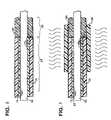
- FIG. 2is a longitudinal section view of catheter segments according to an initial assembly step of a method of the present invention
- FIG. 3is a longitudinal section view of the catheter segments according to another assembly step of the method.
- FIG. 4is a longitudinal section view of the catheter segments joined by the step illustrated in FIG. 3 ;
- FIG. 5is a longitudinal section view of the catheter segments according to another assembly step of a method of the present invention.
- FIG. 6is a longitudinal section view of the catheter segments according to yet another step of a method of the present invention.
- FIG. 7is a longitudinal section view of the catheter segments according to a final assembly step of a method of the present invention.
- FIG. 1is a perspective view of an exemplary medical catheter according to one embodiment of the present invention
- FIG. 1is intended to be representative of any single lumen or multi-lumen medical catheter having at least two catheter body segments that are joined together.
- FIG. 1illustrates a catheter 10 including a catheter body 15 and a hub 50 terminating a proximal end 20 thereof; hub 50 can include any standard medical interconnection, for example a luer fitting, that provides for the introduction of an agent or device through catheter lumen 40 ; hub 50 may further function as a handle and or a connector being configured to manipulate catheter body and or power electrodes (not shown) of catheter 10 .
- FIG. 1further illustrates catheter body 15 including a lumen 40 , extending between proximal catheter body end 20 and a distal catheter body end 25 , a proximal catheter body segment 30 and at least one distal catheter body segment 35 having a length “X” and being joined to segment 30 at junction 85 .
- lumen 40extends over a length “Z” of catheter body 15 , from a lumen distal opening 45 to a lumen proximal opening 55 , and is formed by a tubular inner jacket or liner 65 , which will be described below. Selecting the relative lengths and mechanical characteristics of each of these catheter body segments controls the pushability, torqueability, rupture and kink resistance, and flexibility of catheter body 15 .
- “X”can be selected in a range between approximately 0.2 cm and approximately 30 cm
- “Z”can be selected in a range between approximately 30 cm and approximately 200 cm.
- proximal catheter body segment 30includes a reinforcing layer 70 disposed between inner liner 65 and an outer sheath 75 , as shown in an exposed section 60 in FIG. 1 ; segment 30 may have been cut from a greater length of stock tubing that had been fabricated in bulk according to methods known to those skilled in the art.
- liner 65examples include fluorocarbon polymers, polyamides (e.g., Nylon), polyether block amides (PEBA), polyolefins, and polyimides; according to an exemplary embodiment, liner 65 is extruded of PEBAX® polyether block-polyamide having a hardness in the range of approximately 55D to approximately 70D.
- Layer 70is formed of wire filaments braided together or coiled over and against an outer surface of inner liner 65 in a continuous or discontinuous braiding or winding operation.
- rectangular or flat wire filaments of stainless steelare used to form the braid or coil; for example, a number of flat 304V stainless steel ribbon wires having a tensile strength between approximately 100 kpsi and approximately 400 kpsi are wound under tension into a braid configuration, of typically 20-50 picks per inch, over the outer surface of liner 65 .
- outer sheath 75is formed over reinforcing layer 70 by a continuous extrusion process so that the outer sheath material penetrates interstices between the wire filaments of layer 70 and is of uniform thickness, within acceptable tolerances.
- materials appropriate for outer sheath 75include polyamide polyether block amides, (PEBAX® or VESTAMID®), polyurethane, polyethylene, silicone rubber, polyimides, polyamides, fluorinated hydrocarbon polymers and the like having a hardness in the range from approximately 90A to approximately 75D; outer sheath 75 may be tinted, for example with a blue tint, to provide an attractive and more visible appearance.
- FIG. 1further illustrates distal segment 35 formed by a tube 80 having an outer diameter approximately equal to or less than an outer diameter of outer sheath 75 and a filler segment 125 positioned just proximal to junction 85 ; there is no ridge of increased diameter or groove of decreased diameter at or in proximity to junction 85 .
- tube 80forms a tip or distal catheter body segment 35 being softer or more flexible than proximal segment 30 ; tube 80 may have been cut to length “X” from a longer length of stock tubing that has been extruded, in a continuous extrusion process and examples of materials from which tube 80 is formed include, but are not limited to polyamide polyether block amides (PEBAX® or VESTAMID®), polyurethane, polyethylene, silicone rubber, polyimides, polyamides, fluorinated hydrocarbon polymers. Furthermore, radiopaque materials, for example barium sulfate or platinum particles, may be incorporated into the material selected for fabrication of tube 80 . According to embodiments of the present invention, filler segment 125 has been formed in proximity to junction 85 as a final step of an operation joining proximal and distal catheter body segments 30 and 35 .
- PEBAX® or VESTAMID®polyamide polyether block amides
- radiopaque materialsfor example barium sulfate or platinum particles, may be
- FIGS. 2-7are longitudinal section views of portions of catheter 10 at various points in time during a fabrication method, which is exemplary of embodiments of the present invention.
- FIGS. 2-7illustrate the fabrication method whereby junction 85 and filler segment 125 are formed.
- FIG. 2shows distal segment 35 butted up to proximal segment 30 , both segments being supported by a mandrel 90 , according to an initial step of an exemplary method; according to an alternate step one of segments 30 and 35 may overlap the other segment.
- Mandrel 90may include a fluoropolymer coating.
- FIG. 3shows a tube 100 , for example a PTFE tube, fitted over segments 30 and 35 and spanning the abutting ends of the segments to assure intimate contact therebetween during a thermal fusion process illustrated by wavy lines; a temperature applied during the thermal fusion process should cause both a material forming segment 30 and a material forming segment 35 to melt thereby forming a bond between the materials via intermixing of the materials. Additional longitudinal forces may be applied to segments 30 and 35 to assure their intimate contact during the fusion process.
- outer layer 75 of proximal segment 30is formed of 72D durometer PEBAX® and tube 80 of distal segment 35 is formed of a softer PEBAX®, for example between 55D and 65D durometer; in this case the temperature applied for fusing segments 30 and 35 must be sufficient to melt the harder 72D PEBAX®, for example between approximately 300° and 400° F.
- materials of segments 30 and 35are allowed to cool and solidify and then tube 100 is removed; the resulting junction 85 is illustrated in FIG. 4 .
- FIG. 4further illustrates ends 47 of filament reinforcing layer 70 , in proximity to junction 85 , which have extended out within outer sheath 75 during the fusion step; the heat and or forces applied to segment 30 during fusion has caused filament reinforcing layer to expand and shift.
- ends 47may protrude from an outer surface of outer sheath 75 and or junction 85 while in other cases ends 47 may remain just below the outer surface; since neither case is desirable, ends 47 are removed in a subsequent step according to methods of the present invention.
- FIG. 5illustrates an example of such a fabrication step wherein outwardly extending ends 47 , depicted in FIG. 4 , have been removed by means of a grinding process, which forms channel 140 .
- mandrel 90supports the assembly of segments 30 and 35 and a grinding wheel 160 is mounted to rotate on an axis extending in parallel with the axis of the mandrel 90 .
- the grinding wheel 160may be a conventional grit wheel or a diamond or carbide blade.
- a fixture(not shown) holds mandrel 90 such that a zone of the assembly encompassing ends 47 is positioned in operative relation to the grinding wheel 160 ; with reference to the arrows shown in FIG. 5 , the fixture further moves the assembly laterally toward and away from grinding wheel 160 , rotates the assembly about the axis of mandrel 90 and moves the assembly axially.
- the assembly of segments 30 and 35are moved laterally toward grinding wheel 160 , rotated about the axis of mandrel 90 and moved axially as grinding wheel 160 is rotated so that outer sheath 75 and ends 47 are ground away and channel 140 is formed extending around a circumference of segment 30 ; a micrometer may be employed in the fixture to set stops governing a depth of channel 140 .
- channel 140may further extend lengthwise into segment 35 ; furthermore, the grinding wheel 160 may be of a width corresponding to a predetermined length of channel 140 so that axial movement is unnecessary.
- the length and depth of channel 140along with positions of proximal and distal ends of channel 140 , would be dictated by preprogrammed settings for a computer-controlled fixture.
- FIGS. 6 and 7illustrate an example of such a method.
- FIG. 6illustrates a step of the exemplary method wherein channel 140 is filled with a material 130 , preferably a polymer compatible with the polymers of segments 30 and 35 , adheres well therewith and self-levels in channel 140 .
- filler material 130is a liquid epoxy while, according to a preferred embodiment, filler material 130 is a UV light curable polymer, e.g., a biocompatible UV light curable medical adhesive, and curing is effected by exposing filler 130 to UV light as shown schematically in FIG. 7 .
- a UV light curable polymere.g., a biocompatible UV light curable medical adhesive
- UV light curable polymeris type 1191-M polyurethane oligomer mixture available from Dymax Corp., Torrington, Conn., which includes about 40%-50% polyurethane oligomer suspended in solvents that are driven off during curing; another example is a Loctite® Type 3341 light cured medical adhesive available from Henkel Loctite Corp., Rocky Hill, Conn., which includes about 35%-45% aliphatic polyurethane acrylic oligomers suspended in solvents that are driven off during curing. Both of these light curable polymers cure under UV light in about 30 seconds to form filler segment 125 illustrated in FIG. 1 . Moreover, a Shore durometer or hardness of the resulting filler segment 125 may be selected to be intermediate the Shore durometer of the outer sheath 75 and the distal tube 80 .
- An adhesive applying and curing fixturemay be employed to accomplish the formation of filler segment 125 ; the fixture would support a mandrel, e.g. mandrel 90 on which the assembly of segments 30 and 35 are mounted, and cause rotation and axial movement of the assembly as indicated by the arrows of FIG. 6 while filler 130 is dispensed from a source 135 .
- the fixturemay further include a microscope for an operator to view channel 140 as it is filled.
- filler material 130has a viscosity and surface tension characteristics ensuring that filler 130 remains within the channel 140 and self-levels during such movement of the assembly of segments 30 and 35 .
- FIG. 6 and 7further illustrates the fixture including a UV light source 115 that is turned on, as shown schematically in FIG. 7 , following the filling step of FIG. 6 , to cure filler material 130 ; the assembly of the of segments 30 and 35 is rotated, as shown by the arrow of FIG. 7 , until curing is complete.
- filler 130cures without substantial shrinkage or expansion resulting in catheter body 15 including filler segment 125 as described in conjunction with FIG. 1 .
Landscapes
- Health & Medical Sciences (AREA)
- Life Sciences & Earth Sciences (AREA)
- Biophysics (AREA)
- Pulmonology (AREA)
- Engineering & Computer Science (AREA)
- Anesthesiology (AREA)
- Biomedical Technology (AREA)
- Heart & Thoracic Surgery (AREA)
- Hematology (AREA)
- Animal Behavior & Ethology (AREA)
- General Health & Medical Sciences (AREA)
- Public Health (AREA)
- Veterinary Medicine (AREA)
- Media Introduction/Drainage Providing Device (AREA)
Abstract
Description
The present invention pertains to the manufacture of catheter bodies formed of two or more catheter body segments, and particularly to means for forming junctions between catheter body segments.
Medical catheters are adapted for insertion into a body cavity, duct, tract, organ or blood vessel in order to facilitate any of a wide variety of diagnostic or therapeutic functions. Such catheters generally include an elongated, flexible catheter tube or body whose side wall encloses at least one catheter lumen extending from a proximal catheter body end, which is coupled to a catheter hub, to a distal catheter body end. The catheter body may be relatively straight or inherently curved or curved by insertion of a curved stiffening wire or guide wire or curved by built-in control wire-deflection. The catheter sidewall is typically fabricated and dimensioned to minimize a catheter body outer diameter and sidewall thickness and to maximize the catheter lumen diameter while retaining sufficient sidewall flexibility and strength characteristics to enable the catheter to be used for the intended medical purpose. Examples of medical catheters include but are not limited to electrophysiology catheters, guiding catheters, drainage catheters, perfusion catheters and drug infusion catheters.
Desirable qualities of catheters include a stiffness facilitating torque transfer and pushability balanced with a flexibility facilitating tracking through tortuous anatomy, lumen lubricity to facilitate passage of other catheters or devices or substances therethrough, and a sidewall strength that prevents kinking. Additionally, it is desirable to provide a smooth and relatively soft catheter distal tip, to prevent damage to surrounding tissue as catheter is advanced, and a radiopaque marker near the distal tip to enhance catheter visibility under fluoroscopy. To achieve the aforementioned qualities it may be necessary to form a catheter body from a plurality of segments.
A typical technique employed to join catheter body segments involves assembling a mandrel through the lumens of catheter body segments and then fusing the segments together by means of heat applied while the segments are held within a tube, for example a PTFE tube. Frequently, the joint that is achieved is enlarged or is flawed in other respects. If one of the catheter segments includes reinforcement in the form of braided or coiled wire filaments or strands within a sidewall, the strands, in proximity to the fused joint, may unravel or shift such that they protrude out through the outer surface of the fused joint. This can occur due to a high tensile strength of the wire filaments and the winding tension that is applied during formation of a tight wire braid or coil. There remains a need for a fabrication technique that simplifies fabrication steps and reduces scrap and other costs while retaining desirable characteristics of the catheter body.
The following drawings are illustrative of particular embodiments of the invention and therefore do not limit its scope, but are presented to assist in providing a proper understanding of the invention. The drawings are not to scale (unless so stated) and are intended for use in conjunction with the explanations in the following detailed description. The present invention will hereinafter be described in conjunction with the appended drawings, wherein like numerals denote like elements and:
The following detailed description is exemplary in nature and is not intended to limit the scope, applicability, or configuration of the invention in any way. Rather, the following description provides a practical illustration for implementing exemplary embodiments of the invention.
According to embodiments of the present invention, proximalcatheter body segment 30 includes a reinforcinglayer 70 disposed betweeninner liner 65 and anouter sheath 75, as shown in an exposedsection 60 inFIG. 1 ;segment 30 may have been cut from a greater length of stock tubing that had been fabricated in bulk according to methods known to those skilled in the art. Examples of materials that may be used to formliner 65 include fluorocarbon polymers, polyamides (e.g., Nylon), polyether block amides (PEBA), polyolefins, and polyimides; according to an exemplary embodiment,liner 65 is extruded of PEBAX® polyether block-polyamide having a hardness in the range of approximately 55D to approximately 70D.Layer 70 is formed of wire filaments braided together or coiled over and against an outer surface ofinner liner 65 in a continuous or discontinuous braiding or winding operation. According to an exemplary embodiment, rectangular or flat wire filaments of stainless steel are used to form the braid or coil; for example, a number of flat 304V stainless steel ribbon wires having a tensile strength between approximately 100 kpsi and approximately 400 kpsi are wound under tension into a braid configuration, of typically 20-50 picks per inch, over the outer surface ofliner 65. According to some embodiments of the present invention,outer sheath 75 is formed over reinforcinglayer 70 by a continuous extrusion process so that the outer sheath material penetrates interstices between the wire filaments oflayer 70 and is of uniform thickness, within acceptable tolerances. Examples of materials appropriate forouter sheath 75 include polyamide polyether block amides, (PEBAX® or VESTAMID®), polyurethane, polyethylene, silicone rubber, polyimides, polyamides, fluorinated hydrocarbon polymers and the like having a hardness in the range from approximately 90A to approximately 75D;outer sheath 75 may be tinted, for example with a blue tint, to provide an attractive and more visible appearance.
According to the method step illustrated inFIG. 5 , the assembly ofsegments grinding wheel 160, rotated about the axis ofmandrel 90 and moved axially asgrinding wheel 160 is rotated so thatouter sheath 75 andends 47 are ground away andchannel 140 is formed extending around a circumference ofsegment 30; a micrometer may be employed in the fixture to set stops governing a depth ofchannel 140. According to an alternate embodiment,channel 140 may further extend lengthwise intosegment 35; furthermore, thegrinding wheel 160 may be of a width corresponding to a predetermined length ofchannel 140 so that axial movement is unnecessary. In a fully automated assembly process, the length and depth ofchannel 140, along with positions of proximal and distal ends ofchannel 140, would be dictated by preprogrammed settings for a computer-controlled fixture.
Whether outwardly extendingends 47 are removed according to the process described in conjunction withFIG. 5 or according to an alternate process, preferred embodiments of the present invention further include a method filling voids left by the removedends 47;FIGS. 6 and 7 illustrate an example of such a method.FIG. 6 illustrates a step of the exemplary method whereinchannel 140 is filled with amaterial 130, preferably a polymer compatible with the polymers ofsegments channel 140. According to oneembodiment filler material 130 is a liquid epoxy while, according to a preferred embodiment,filler material 130 is a UV light curable polymer, e.g., a biocompatible UV light curable medical adhesive, and curing is effected by exposingfiller 130 to UV light as shown schematically inFIG. 7 . An example of an appropriate UV light curable polymer is type 1191-M polyurethane oligomer mixture available from Dymax Corp., Torrington, Conn., which includes about 40%-50% polyurethane oligomer suspended in solvents that are driven off during curing; another example is a Loctite® Type 3341 light cured medical adhesive available from Henkel Loctite Corp., Rocky Hill, Conn., which includes about 35%-45% aliphatic polyurethane acrylic oligomers suspended in solvents that are driven off during curing. Both of these light curable polymers cure under UV light in about 30 seconds to formfiller segment 125 illustrated inFIG. 1 . Moreover, a Shore durometer or hardness of the resultingfiller segment 125 may be selected to be intermediate the Shore durometer of theouter sheath 75 and thedistal tube 80.
An adhesive applying and curing fixture may be employed to accomplish the formation offiller segment 125; the fixture would support a mandrel,e.g. mandrel 90 on which the assembly ofsegments FIG. 6 whilefiller 130 is dispensed from asource 135. The fixture may further include a microscope for an operator to viewchannel 140 as it is filled. According to preferred embodiments,filler material 130 has a viscosity and surface tension characteristics ensuring thatfiller 130 remains within thechannel 140 and self-levels during such movement of the assembly ofsegments FIGS. 6 and 7 further illustrates the fixture including aUV light source 115 that is turned on, as shown schematically inFIG. 7 , following the filling step ofFIG. 6 , to curefiller material 130; the assembly of the ofsegments FIG. 7 , until curing is complete. Preferably,filler 130 cures without substantial shrinkage or expansion resulting incatheter body 15 includingfiller segment 125 as described in conjunction withFIG. 1 .
In the foregoing detailed description, the invention has been described with reference to specific embodiments. However, it may be appreciated that various modifications and changes can be made without departing from the scope of the invention as set forth in the appended claims.
Claims (29)
1. A catheter fabrication method, comprising the steps of:
joining a first catheter body segment, the first segment including a braided or coiled filament reinforcing layer contained within an outer layer, to a second catheter body segment by thermal fusion in a zone including an interface between the first segment and the second segment and at a temperature causing ends of the filament reinforcing layer in the zone to extend outward within the outer layer; and
removing the extending ends of the filament reinforcing layer.
2. The method ofclaim 1 , wherein the step of removing the extending ends creates a channel in an outer surface of the outer layer.
3. The method ofclaim 1 , wherein the step of removing the extending ends creates a channel in an outer surface of the outer layer and in an outer surface of the second catheter segment.
4. The method ofclaim 1 , wherein the step of removing the extending ends comprises grinding away the extending ends.
5. The method ofclaim 1 , further comprising the step of filling a void left by the removed extending ends with a material.
6. The method ofclaim 2 , further comprising the step of filling the channel with a material to create a smooth transition between the outer surface of the outer layer and an outer surface of the second catheter segment.
7. The method ofclaim 6 , wherein the material is an epoxy.
8. The method ofclaim 6 , wherein the material is a polymer.
9. The method ofclaim 6 , further comprising the step of curing the material filling the channel.
10. The method ofclaim 9 , wherein the material is a UV light curable polymer.
11. The method ofclaim 6 , wherein the material has a hardness greater than that of the second segment.
12. The method ofclaim 6 , wherein the material has a hardness less than that of the outer layer of the first segment.
13. The method ofclaim 1 , wherein:
the outer layer of the first segment is formed of a polyether block amide having a hardness between approximately 70 and approximately 75 on a Shore D scale and the second segment is formed of a polyether block amide having a hardness between approximately 50 and approximately 70 on a Shore D scale; and
the thermal fusion temperature is between approximately 300° F. and approximately 400° F.
14. A catheter fabrication method, comprising the steps of:
joining a first catheter body segment, the first segment including a braided or coiled filament reinforcing layer contained within an outer layer, to a second catheter body segment by thermal fusion in a zone including an interface between the first segment and the second segment and at a temperature causing ends of the filament reinforcing layer in the zone to extend outward within the outer layer;
removing the extending ends of the filament reinforcing layer and thereby creating a channel in an outer surface of the outer layer; and
filling the channel with a material to create a smooth transition between an outer surface of the outer layer and an outer surface of the second catheter segment.
15. The method ofclaim 14 , wherein the step of removing the extending ends comprises grinding away the extending ends.
16. The method ofclaim 14 , wherein the material is an epoxy.
17. The method ofclaim 14 , wherein the material is a polymer.
18. The method ofclaim 14 , further comprising the step of curing the material filling the channel.
19. The method ofclaim 18 , wherein the material is a UV light curable polymer.
20. The method ofclaim 14 , wherein the material has a hardness greater than that of the second segment.
21. The method ofclaim 14 , wherein the material has a hardness less than that of the outer layer of the first segment.
22. The method ofclaim 14 , wherein:
the outer layer of the first segment is formed of a polyether block amide having a hardness between approximately 70 and approximately 75 on a Shore D scale and the second segment is formed of a polyether block amide having a hardness between approximately 50 and approximately 70 on a Shore D scale; and
the thermal fusion temperature is between approximately 300° F. and approximately 400° F.
23. A catheter, comprising:
a first catheter body segment including a braided or coiled filament reinforcing layer contained within an outer layer;
a second catheter body segment joined to the first catheter body segment by thermal fusion; and
a zone, in close proximity to the junction of the first segment and the second segment, including a channel, the channel having been formed by removing ends of the filament reinforcing layer and being filled with a material to create a smooth transition between an outer surface of the outer layer and an outer surface of the second catheter segment;
wherein the ends of the filament reinforcing layer were caused to extend outward within the outer layer by the thermal fusion.
24. The catheter ofclaim 23 , wherein the material is a UV light curable polymer.
25. The catheter ofclaim 23 , wherein the material has a hardness greater than that of the second segment.
26. The catheter ofclaim 23 , wherein the material has a hardness less than that of the outer layer of the first segment.
27. The catheter ofclaim 23 , wherein the outer layer of the first segment is formed of a polyether block amide having a hardness between approximately 70 and approximately 75 on a Shore D scale and the second segment is formed of a polyether block amide having a hardness between approximately 50 and approximately 70 on a Shore D scale.
28. A catheter fabrication method, comprising the steps of:
joining a first catheter body segment, the first segment including a braided or coiled filament reinforcing layer contained within an outer layer, to a second catheter body segment by thermal fusion in a zone including a butt joint between the first segment and the second segment and at a temperature causing ends of the filament reinforcing layer in the zone to extend outward within the outer layer;
removing the extending ends of the filament reinforcing layer and thereby creating a channel spanning a portion of an outer surface of the first segment and a portion of an outer surface of the second segment; and
filling the channel with a material to create a smooth transition between the outer surface of the first segment and the outer surface of the second segment;
wherein the joining comprises
placing a heat-resistant tube spanning the butt joint prior to the thermal fusion process to promote intimate contact of the first and second segments; and
removing the tube subsequent to the thermal fusion process.
29. A catheter fabrication method, comprising the steps of:
joining a first catheter body segment, the first segment including a braided filament reinforcing layer contained within an outer layer, to a second catheter body segment by thermal fusion in a zone including an interface between the first segment and the second segment and at a temperature causing ends of the filament reinforcing layer in the zone to extend outward within the outer layer; and
removing a portion of the braided filament reinforcing layer.
Priority Applications (1)
| Application Number | Priority Date | Filing Date | Title |
|---|---|---|---|
| US10/871,588US7331948B2 (en) | 2004-06-18 | 2004-06-18 | Catheter and catheter fabrication method |
Applications Claiming Priority (1)
| Application Number | Priority Date | Filing Date | Title |
|---|---|---|---|
| US10/871,588US7331948B2 (en) | 2004-06-18 | 2004-06-18 | Catheter and catheter fabrication method |
Publications (2)
| Publication Number | Publication Date |
|---|---|
| US20050283136A1 US20050283136A1 (en) | 2005-12-22 |
| US7331948B2true US7331948B2 (en) | 2008-02-19 |
Family
ID=35481612
Family Applications (1)
| Application Number | Title | Priority Date | Filing Date |
|---|---|---|---|
| US10/871,588Expired - LifetimeUS7331948B2 (en) | 2004-06-18 | 2004-06-18 | Catheter and catheter fabrication method |
Country Status (1)
| Country | Link |
|---|---|
| US (1) | US7331948B2 (en) |
Cited By (58)
| Publication number | Priority date | Publication date | Assignee | Title |
|---|---|---|---|---|
| US20060224129A1 (en)* | 1998-12-07 | 2006-10-05 | Beasley Jim C | Septum including at least one identifiable feature, access ports including same, and related methods |
| US20060247584A1 (en)* | 2005-03-04 | 2006-11-02 | C.R. Bard, Inc. | Access port identification systems and methods |
| US20060264898A1 (en)* | 2005-04-27 | 2006-11-23 | Beasley Jim C | Infusion apparatuses and related methods |
| US20070233017A1 (en)* | 2006-10-18 | 2007-10-04 | Medical Components, Inc. | Venous access port assembly with radiopaque indicia |
| US20080319399A1 (en)* | 2007-06-20 | 2008-12-25 | Medical Components, Inc. | Venous access port with molded and/or radiopaque indicia |
| US20090024024A1 (en)* | 2007-07-19 | 2009-01-22 | Innovative Medical Devices, Llc | Venous Access Port Assembly with X-Ray Discernable Indicia |
| US20100069743A1 (en)* | 2005-03-04 | 2010-03-18 | C. R. Bard, Inc. | Systems and methods for identifying an access port |
| US20100191165A1 (en)* | 2009-01-29 | 2010-07-29 | Angiodynamics, Inc. | Multilumen Catheters and Method of Manufacturing |
| US20110054312A1 (en)* | 2004-07-20 | 2011-03-03 | Barbara Bell | Reinforced Venous Access Catheter |
| US7947022B2 (en) | 2005-03-04 | 2011-05-24 | C. R. Bard, Inc. | Access port identification systems and methods |
| US8021324B2 (en)* | 2007-07-19 | 2011-09-20 | Medical Components, Inc. | Venous access port assembly with X-ray discernable indicia |
| US20110238041A1 (en)* | 2010-03-24 | 2011-09-29 | Chestnut Medical Technologies, Inc. | Variable flexibility catheter |
| US8029482B2 (en) | 2005-03-04 | 2011-10-04 | C. R. Bard, Inc. | Systems and methods for radiographically identifying an access port |
| USD676955S1 (en) | 2010-12-30 | 2013-02-26 | C. R. Bard, Inc. | Implantable access port |
| USD682416S1 (en) | 2010-12-30 | 2013-05-14 | C. R. Bard, Inc. | Implantable access port |
| US20130231651A1 (en)* | 2012-03-02 | 2013-09-05 | Ron Burr | Cryosurgery system |
| US8641676B2 (en) | 2005-04-27 | 2014-02-04 | C. R. Bard, Inc. | Infusion apparatuses and methods of use |
| US8715244B2 (en) | 2009-07-07 | 2014-05-06 | C. R. Bard, Inc. | Extensible internal bolster for a medical device |
| US8864730B2 (en) | 2005-04-12 | 2014-10-21 | Rochester Medical Corporation | Silicone rubber male external catheter with absorbent and adhesive |
| US8932271B2 (en) | 2008-11-13 | 2015-01-13 | C. R. Bard, Inc. | Implantable medical devices including septum-based indicators |
| US8968383B1 (en) | 2013-08-27 | 2015-03-03 | Covidien Lp | Delivery of medical devices |
| US8998882B2 (en) | 2013-03-13 | 2015-04-07 | C. R. Bard, Inc. | Enhanced pre-wetted intermittent catheter with lubricious coating |
| US9033149B2 (en) | 2010-03-04 | 2015-05-19 | C. R. Bard, Inc. | Catheter assembly/package utilizing a hydrating/hydrogel sleeve and a foil outer layer and method of making and using the same |
| US9079004B2 (en) | 2009-11-17 | 2015-07-14 | C. R. Bard, Inc. | Overmolded access port including anchoring and identification features |
| US9144449B2 (en) | 2012-03-02 | 2015-09-29 | Csa Medical, Inc. | Cryosurgery system |
| US9265912B2 (en) | 2006-11-08 | 2016-02-23 | C. R. Bard, Inc. | Indicia informative of characteristics of insertable medical devices |
| US9332998B2 (en) | 2012-08-13 | 2016-05-10 | Covidien Lp | Apparatus and methods for clot disruption and evacuation |
| US9332999B2 (en) | 2012-08-13 | 2016-05-10 | Covidien Lp | Apparatus and methods for clot disruption and evacuation |
| US9474888B2 (en) | 2005-03-04 | 2016-10-25 | C. R. Bard, Inc. | Implantable access port including a sandwiched radiopaque insert |
| US9579496B2 (en) | 2007-11-07 | 2017-02-28 | C. R. Bard, Inc. | Radiopaque and septum-based indicators for a multi-lumen implantable port |
| US9642986B2 (en) | 2006-11-08 | 2017-05-09 | C. R. Bard, Inc. | Resource information key for an insertable medical device |
| US9707375B2 (en) | 2011-03-14 | 2017-07-18 | Rochester Medical Corporation, a subsidiary of C. R. Bard, Inc. | Catheter grip and method |
| US9782186B2 (en) | 2013-08-27 | 2017-10-10 | Covidien Lp | Vascular intervention system |
| US9821139B2 (en) | 2009-08-13 | 2017-11-21 | C. R. Bard, Inc. | Catheter having internal hydrating fluid storage and/or catheter package using the same and method of making and/or using the same |
| US9867648B2 (en) | 2014-06-04 | 2018-01-16 | Csa Medical, Inc. | Method and system for consistent, repeatable, and safe cryospray treatment of airway tissue |
| US9872969B2 (en) | 2012-11-20 | 2018-01-23 | Rochester Medical Corporation, a subsidiary of C.R. Bard, Inc. | Catheter in bag without additional packaging |
| US10092728B2 (en) | 2012-11-20 | 2018-10-09 | Rochester Medical Corporation, a subsidiary of C.R. Bard, Inc. | Sheath for securing urinary catheter |
| US10149961B2 (en) | 2009-07-29 | 2018-12-11 | C. R. Bard, Inc. | Catheter having improved drainage and/or a retractable sleeve and method of using the same |
| US10307581B2 (en) | 2005-04-27 | 2019-06-04 | C. R. Bard, Inc. | Reinforced septum for an implantable medical device |
| US10376396B2 (en) | 2017-01-19 | 2019-08-13 | Covidien Lp | Coupling units for medical device delivery systems |
| US10537452B2 (en) | 2012-02-23 | 2020-01-21 | Covidien Lp | Luminal stenting |
| US10786377B2 (en) | 2018-04-12 | 2020-09-29 | Covidien Lp | Medical device delivery |
| US10857324B2 (en) | 2014-08-26 | 2020-12-08 | C. R. Bard, Inc. | Urinary catheter |
| US10912917B2 (en) | 2009-12-23 | 2021-02-09 | C. R. Bard, Inc. | Catheter assembly/package utilizing a hydrating/hydrogel sleeve and method of making and using the same |
| US10940293B2 (en) | 2016-11-24 | 2021-03-09 | Asahi Intecc Co., Ltd. | Catheter and balloon catheter |
| US11071637B2 (en) | 2018-04-12 | 2021-07-27 | Covidien Lp | Medical device delivery |
| US11123209B2 (en) | 2018-04-12 | 2021-09-21 | Covidien Lp | Medical device delivery |
| US11202559B2 (en) | 2016-04-27 | 2021-12-21 | Csa Medical, Inc. | Vision preservation system for medical devices |
| US11413176B2 (en) | 2018-04-12 | 2022-08-16 | Covidien Lp | Medical device delivery |
| US11413174B2 (en) | 2019-06-26 | 2022-08-16 | Covidien Lp | Core assembly for medical device delivery systems |
| US11547599B2 (en) | 2017-09-19 | 2023-01-10 | C. R. Bard, Inc. | Urinary catheter bridging device, systems and methods thereof |
| US11871977B2 (en) | 2016-05-19 | 2024-01-16 | Csa Medical, Inc. | Catheter extension control |
| US11890443B2 (en) | 2008-11-13 | 2024-02-06 | C. R. Bard, Inc. | Implantable medical devices including septum-based indicators |
| US11944558B2 (en) | 2021-08-05 | 2024-04-02 | Covidien Lp | Medical device delivery devices, systems, and methods |
| US12042413B2 (en) | 2021-04-07 | 2024-07-23 | Covidien Lp | Delivery of medical devices |
| US12048469B2 (en) | 2013-03-04 | 2024-07-30 | Csa Medical, Inc. | Cryospray catheters |
| US12109137B2 (en) | 2021-07-30 | 2024-10-08 | Covidien Lp | Medical device delivery |
| US12397129B2 (en) | 2015-07-30 | 2025-08-26 | Normedix, Inc. | Coronary guide catheter |
Families Citing this family (29)
| Publication number | Priority date | Publication date | Assignee | Title |
|---|---|---|---|---|
| US8328792B2 (en) | 2005-10-27 | 2012-12-11 | C. R. Bard, Inc. | Enhanced pre-wetted intermittent catheter with lubricious coating |
| US7637902B2 (en)* | 2005-11-23 | 2009-12-29 | Medtronic, Inc. | Slittable and peelable sheaths and methods for making and using them |
| US7914841B2 (en)* | 2006-02-09 | 2011-03-29 | Cook Medical Technologies Llc | Inline application of coatings |
| US10226919B2 (en) | 2007-07-18 | 2019-03-12 | Voxeljet Ag | Articles and structures prepared by three-dimensional printing method |
| DE102007049058A1 (en)* | 2007-10-11 | 2009-04-16 | Voxeljet Technology Gmbh | Material system and method for modifying properties of a plastic component |
| DE102008058378A1 (en) | 2008-11-20 | 2010-05-27 | Voxeljet Technology Gmbh | Process for the layered construction of plastic models |
| DE102010014969A1 (en) | 2010-04-14 | 2011-10-20 | Voxeljet Technology Gmbh | Device for producing three-dimensional models |
| DE102010056346A1 (en) | 2010-12-29 | 2012-07-05 | Technische Universität München | Method for the layered construction of models |
| DE102012010272A1 (en) | 2012-05-25 | 2013-11-28 | Voxeljet Technology Gmbh | Method for producing three-dimensional models with special construction platforms and drive systems |
| DE102012012363A1 (en) | 2012-06-22 | 2013-12-24 | Voxeljet Technology Gmbh | Apparatus for building up a layer body with a storage or filling container movable along the discharge container |
| DE102012020000A1 (en) | 2012-10-12 | 2014-04-17 | Voxeljet Ag | 3D multi-stage process |
| DE102013004940A1 (en) | 2012-10-15 | 2014-04-17 | Voxeljet Ag | Method and device for producing three-dimensional models with tempered printhead |
| DE102013003303A1 (en) | 2013-02-28 | 2014-08-28 | FluidSolids AG | Process for producing a molded part with a water-soluble casting mold and material system for its production |
| JP6089876B2 (en)* | 2013-03-28 | 2017-03-08 | 住友ベークライト株式会社 | Medical equipment |
| DE102013018182A1 (en) | 2013-10-30 | 2015-04-30 | Voxeljet Ag | Method and device for producing three-dimensional models with binder system |
| DE102013018031A1 (en) | 2013-12-02 | 2015-06-03 | Voxeljet Ag | Swap body with movable side wall |
| DE102013020491A1 (en) | 2013-12-11 | 2015-06-11 | Voxeljet Ag | 3D infiltration process |
| DE102014004692A1 (en) | 2014-03-31 | 2015-10-15 | Voxeljet Ag | Method and apparatus for 3D printing with conditioned process control |
| DE102014007584A1 (en) | 2014-05-26 | 2015-11-26 | Voxeljet Ag | 3D reverse printing method and apparatus |
| CN106573294B (en) | 2014-08-02 | 2021-01-01 | 沃克斯艾捷特股份有限公司 | Method and casting mould, in particular for a cold casting method |
| DE102015006533A1 (en) | 2014-12-22 | 2016-06-23 | Voxeljet Ag | Method and device for producing 3D molded parts with layer construction technique |
| DE102015006363A1 (en) | 2015-05-20 | 2016-12-15 | Voxeljet Ag | Phenolic resin method |
| DE102015011503A1 (en) | 2015-09-09 | 2017-03-09 | Voxeljet Ag | Method for applying fluids |
| DE102015011790A1 (en) | 2015-09-16 | 2017-03-16 | Voxeljet Ag | Device and method for producing three-dimensional molded parts |
| DE102015015353A1 (en) | 2015-12-01 | 2017-06-01 | Voxeljet Ag | Method and device for producing three-dimensional components by means of an excess quantity sensor |
| DE102015016464B4 (en) | 2015-12-21 | 2024-04-25 | Voxeljet Ag | Method and device for producing 3D molded parts |
| CN110678219A (en)* | 2017-04-28 | 2020-01-10 | 美国医疗设备有限公司 | Interposer with partially annealed reinforcement element and related systems and methods |
| WO2021212110A1 (en) | 2020-04-17 | 2021-10-21 | Eagle Engineered Solutions, Inc. | Powder spreading apparatus and system |
| CN116077800B (en)* | 2022-12-08 | 2024-10-11 | 美度可医疗科技(上海)有限公司 | Bridging method for solving butt joint strength and sealing performance of multi-section catheter |
Citations (19)
| Publication number | Priority date | Publication date | Assignee | Title |
|---|---|---|---|---|
| US4283447A (en) | 1979-05-18 | 1981-08-11 | Flynn Vincent J | Radiopaque polyurethane resin compositions |
| US4321226A (en) | 1979-02-19 | 1982-03-23 | A/S Surgimed | Method and apparatus for making tubular products such as catheters |
| US4531943A (en) | 1983-08-08 | 1985-07-30 | Angiomedics Corporation | Catheter with soft deformable tip |
| US4551292A (en) | 1984-04-05 | 1985-11-05 | Angiomedics, Inc. | Method for making a catheter with a soft, deformable tip |
| US4817613A (en) | 1987-07-13 | 1989-04-04 | Devices For Vascular Intervention, Inc. | Guiding catheter |
| US5078702A (en) | 1988-03-25 | 1992-01-07 | Baxter International Inc. | Soft tip catheters |
| US5221270A (en)* | 1991-06-28 | 1993-06-22 | Cook Incorporated | Soft tip guiding catheter |
| US5234416A (en) | 1991-06-06 | 1993-08-10 | Advanced Cardiovascular Systems, Inc. | Intravascular catheter with a nontraumatic distal tip |
| US5509910A (en) | 1994-05-02 | 1996-04-23 | Medtronic, Inc. | Method of soft tip attachment for thin walled catheters |
| US5545149A (en)* | 1993-06-25 | 1996-08-13 | Medtronic, Inc. | Method of catheter segment attachment |
| US5676659A (en)* | 1993-11-12 | 1997-10-14 | Medtronic, Inc. | Small diameter, high torque catheter |
| US5738742A (en)* | 1996-11-12 | 1998-04-14 | Stevens; Robert C. | Method for making angiographic catheters |
| US5769796A (en)* | 1993-05-11 | 1998-06-23 | Target Therapeutics, Inc. | Super-elastic composite guidewire |
| US5964971A (en)* | 1996-10-29 | 1999-10-12 | Medtronic, Inc. | Thinwall guide catheter |
| US5972143A (en)* | 1996-11-12 | 1999-10-26 | Stevens; Robert C. | Angiographic catheter with unitary body and tip sections and method for making same from a continuous feedstock |
| US6042578A (en)* | 1996-05-13 | 2000-03-28 | Schneider (Usa) Inc. | Catheter reinforcing braids |
| US6106510A (en) | 1998-05-28 | 2000-08-22 | Medtronic, Inc. | Extruded guide catheter shaft with bump extrusion soft distal segment |
| US6375774B1 (en) | 1998-10-02 | 2002-04-23 | Medtronic, Inc. | Method of making a medical catheter with grooved soft distal segment |
| US6591472B1 (en)* | 1998-12-08 | 2003-07-15 | Medtronic, Inc. | Multiple segment catheter and method of fabrication |
- 2004
- 2004-06-18USUS10/871,588patent/US7331948B2/ennot_activeExpired - Lifetime
Patent Citations (19)
| Publication number | Priority date | Publication date | Assignee | Title |
|---|---|---|---|---|
| US4321226A (en) | 1979-02-19 | 1982-03-23 | A/S Surgimed | Method and apparatus for making tubular products such as catheters |
| US4283447A (en) | 1979-05-18 | 1981-08-11 | Flynn Vincent J | Radiopaque polyurethane resin compositions |
| US4531943A (en) | 1983-08-08 | 1985-07-30 | Angiomedics Corporation | Catheter with soft deformable tip |
| US4551292A (en) | 1984-04-05 | 1985-11-05 | Angiomedics, Inc. | Method for making a catheter with a soft, deformable tip |
| US4817613A (en) | 1987-07-13 | 1989-04-04 | Devices For Vascular Intervention, Inc. | Guiding catheter |
| US5078702A (en) | 1988-03-25 | 1992-01-07 | Baxter International Inc. | Soft tip catheters |
| US5234416A (en) | 1991-06-06 | 1993-08-10 | Advanced Cardiovascular Systems, Inc. | Intravascular catheter with a nontraumatic distal tip |
| US5221270A (en)* | 1991-06-28 | 1993-06-22 | Cook Incorporated | Soft tip guiding catheter |
| US5769796A (en)* | 1993-05-11 | 1998-06-23 | Target Therapeutics, Inc. | Super-elastic composite guidewire |
| US5545149A (en)* | 1993-06-25 | 1996-08-13 | Medtronic, Inc. | Method of catheter segment attachment |
| US5676659A (en)* | 1993-11-12 | 1997-10-14 | Medtronic, Inc. | Small diameter, high torque catheter |
| US5509910A (en) | 1994-05-02 | 1996-04-23 | Medtronic, Inc. | Method of soft tip attachment for thin walled catheters |
| US6042578A (en)* | 1996-05-13 | 2000-03-28 | Schneider (Usa) Inc. | Catheter reinforcing braids |
| US5964971A (en)* | 1996-10-29 | 1999-10-12 | Medtronic, Inc. | Thinwall guide catheter |
| US5738742A (en)* | 1996-11-12 | 1998-04-14 | Stevens; Robert C. | Method for making angiographic catheters |
| US5972143A (en)* | 1996-11-12 | 1999-10-26 | Stevens; Robert C. | Angiographic catheter with unitary body and tip sections and method for making same from a continuous feedstock |
| US6106510A (en) | 1998-05-28 | 2000-08-22 | Medtronic, Inc. | Extruded guide catheter shaft with bump extrusion soft distal segment |
| US6375774B1 (en) | 1998-10-02 | 2002-04-23 | Medtronic, Inc. | Method of making a medical catheter with grooved soft distal segment |
| US6591472B1 (en)* | 1998-12-08 | 2003-07-15 | Medtronic, Inc. | Multiple segment catheter and method of fabrication |
Cited By (148)
| Publication number | Priority date | Publication date | Assignee | Title |
|---|---|---|---|---|
| US8608713B2 (en) | 1998-12-07 | 2013-12-17 | C. R. Bard, Inc. | Septum feature for identification of an access port |
| US8177762B2 (en) | 1998-12-07 | 2012-05-15 | C. R. Bard, Inc. | Septum including at least one identifiable feature, access ports including same, and related methods |
| US20060224129A1 (en)* | 1998-12-07 | 2006-10-05 | Beasley Jim C | Septum including at least one identifiable feature, access ports including same, and related methods |
| US20110054312A1 (en)* | 2004-07-20 | 2011-03-03 | Barbara Bell | Reinforced Venous Access Catheter |
| US10179230B2 (en) | 2005-03-04 | 2019-01-15 | Bard Peripheral Vascular, Inc. | Systems and methods for radiographically identifying an access port |
| US11077291B2 (en) | 2005-03-04 | 2021-08-03 | Bard Peripheral Vascular, Inc. | Implantable access port including a sandwiched radiopaque insert |
| US20100069743A1 (en)* | 2005-03-04 | 2010-03-18 | C. R. Bard, Inc. | Systems and methods for identifying an access port |
| US10265512B2 (en) | 2005-03-04 | 2019-04-23 | Bard Peripheral Vascular, Inc. | Implantable access port including a sandwiched radiopaque insert |
| US20100211026A2 (en)* | 2005-03-04 | 2010-08-19 | C. R. Bard, Inc. | Access port identification systems and methods |
| US7785302B2 (en) | 2005-03-04 | 2010-08-31 | C. R. Bard, Inc. | Access port identification systems and methods |
| US10857340B2 (en) | 2005-03-04 | 2020-12-08 | Bard Peripheral Vascular, Inc. | Systems and methods for radiographically identifying an access port |
| US7947022B2 (en) | 2005-03-04 | 2011-05-24 | C. R. Bard, Inc. | Access port identification systems and methods |
| US7959615B2 (en) | 2005-03-04 | 2011-06-14 | C. R. Bard, Inc. | Access port identification systems and methods |
| US10238850B2 (en) | 2005-03-04 | 2019-03-26 | Bard Peripheral Vascular, Inc. | Systems and methods for radiographically identifying an access port |
| US20060247584A1 (en)* | 2005-03-04 | 2006-11-02 | C.R. Bard, Inc. | Access port identification systems and methods |
| US10905868B2 (en) | 2005-03-04 | 2021-02-02 | Bard Peripheral Vascular, Inc. | Systems and methods for radiographically identifying an access port |
| US8029482B2 (en) | 2005-03-04 | 2011-10-04 | C. R. Bard, Inc. | Systems and methods for radiographically identifying an access port |
| US10675401B2 (en) | 2005-03-04 | 2020-06-09 | Bard Peripheral Vascular, Inc. | Access port identification systems and methods |
| US8202259B2 (en) | 2005-03-04 | 2012-06-19 | C. R. Bard, Inc. | Systems and methods for identifying an access port |
| US9682186B2 (en) | 2005-03-04 | 2017-06-20 | C. R. Bard, Inc. | Access port identification systems and methods |
| US8382723B2 (en) | 2005-03-04 | 2013-02-26 | C. R. Bard, Inc. | Access port identification systems and methods |
| US9603992B2 (en) | 2005-03-04 | 2017-03-28 | C. R. Bard, Inc. | Access port identification systems and methods |
| US8382724B2 (en) | 2005-03-04 | 2013-02-26 | C. R. Bard, Inc. | Systems and methods for radiographically identifying an access port |
| US9603993B2 (en) | 2005-03-04 | 2017-03-28 | C. R. Bard, Inc. | Access port identification systems and methods |
| US9474888B2 (en) | 2005-03-04 | 2016-10-25 | C. R. Bard, Inc. | Implantable access port including a sandwiched radiopaque insert |
| US8603052B2 (en) | 2005-03-04 | 2013-12-10 | C. R. Bard, Inc. | Access port identification systems and methods |
| US8998860B2 (en) | 2005-03-04 | 2015-04-07 | C. R. Bard, Inc. | Systems and methods for identifying an access port |
| US8939947B2 (en) | 2005-03-04 | 2015-01-27 | C. R. Bard, Inc. | Systems and methods for radiographically identifying an access port |
| US8585663B2 (en) | 2005-03-04 | 2013-11-19 | C. R. Bard, Inc. | Access port identification systems and methods |
| US9248058B2 (en) | 2005-04-12 | 2016-02-02 | Rochester Medical Corporation, a subsidiary of C.R. Bard, Inc. | Male external catheter with absorbent and adhesive |
| US8864730B2 (en) | 2005-04-12 | 2014-10-21 | Rochester Medical Corporation | Silicone rubber male external catheter with absorbent and adhesive |
| US10016585B2 (en) | 2005-04-27 | 2018-07-10 | Bard Peripheral Vascular, Inc. | Assemblies for identifying a power injectable access port |
| US8475417B2 (en) | 2005-04-27 | 2013-07-02 | C. R. Bard, Inc. | Assemblies for identifying a power injectable access port |
| US8025639B2 (en) | 2005-04-27 | 2011-09-27 | C. R. Bard, Inc. | Methods of power injecting a fluid through an access port |
| US8805478B2 (en) | 2005-04-27 | 2014-08-12 | C. R. Bard, Inc. | Methods of performing a power injection procedure including identifying features of a subcutaneously implanted access port for delivery of contrast media |
| US10183157B2 (en) | 2005-04-27 | 2019-01-22 | Bard Peripheral Vascular, Inc. | Assemblies for identifying a power injectable access port |
| US8641688B2 (en) | 2005-04-27 | 2014-02-04 | C. R. Bard, Inc. | Assemblies for identifying a power injectable access port |
| US10780257B2 (en) | 2005-04-27 | 2020-09-22 | Bard Peripheral Vascular, Inc. | Assemblies for identifying a power injectable access port |
| US10052470B2 (en) | 2005-04-27 | 2018-08-21 | Bard Peripheral Vascular, Inc. | Assemblies for identifying a power injectable access port |
| US9421352B2 (en) | 2005-04-27 | 2016-08-23 | C. R. Bard, Inc. | Infusion apparatuses and methods of use |
| US8545460B2 (en) | 2005-04-27 | 2013-10-01 | C. R. Bard, Inc. | Infusion apparatuses and related methods |
| US10307581B2 (en) | 2005-04-27 | 2019-06-04 | C. R. Bard, Inc. | Reinforced septum for an implantable medical device |
| US10661068B2 (en) | 2005-04-27 | 2020-05-26 | Bard Peripheral Vascular, Inc. | Assemblies for identifying a power injectable access port |
| US8641676B2 (en) | 2005-04-27 | 2014-02-04 | C. R. Bard, Inc. | Infusion apparatuses and methods of use |
| US9937337B2 (en) | 2005-04-27 | 2018-04-10 | C. R. Bard, Inc. | Assemblies for identifying a power injectable access port |
| US20060264898A1 (en)* | 2005-04-27 | 2006-11-23 | Beasley Jim C | Infusion apparatuses and related methods |
| US10625065B2 (en) | 2005-04-27 | 2020-04-21 | Bard Peripheral Vascular, Inc. | Assemblies for identifying a power injectable access port |
| US11878137B2 (en) | 2006-10-18 | 2024-01-23 | Medical Components, Inc. | Venous access port assembly with X-ray discernable indicia |
| US20070233017A1 (en)* | 2006-10-18 | 2007-10-04 | Medical Components, Inc. | Venous access port assembly with radiopaque indicia |
| US9642986B2 (en) | 2006-11-08 | 2017-05-09 | C. R. Bard, Inc. | Resource information key for an insertable medical device |
| US10556090B2 (en) | 2006-11-08 | 2020-02-11 | C. R. Bard, Inc. | Resource information key for an insertable medical device |
| US9265912B2 (en) | 2006-11-08 | 2016-02-23 | C. R. Bard, Inc. | Indicia informative of characteristics of insertable medical devices |
| US10092725B2 (en) | 2006-11-08 | 2018-10-09 | C. R. Bard, Inc. | Resource information key for an insertable medical device |
| US11406808B2 (en) | 2007-06-20 | 2022-08-09 | Medical Components, Inc. | Venous access port with molded and/or radiopaque indicia |
| US11938296B2 (en) | 2007-06-20 | 2024-03-26 | Medical Components, Inc. | Venous access port with molded and/or radiopaque indicia |
| US9533133B2 (en) | 2007-06-20 | 2017-01-03 | Medical Components, Inc. | Venous access port with molded and/or radiopaque indicia |
| US20080319399A1 (en)* | 2007-06-20 | 2008-12-25 | Medical Components, Inc. | Venous access port with molded and/or radiopaque indicia |
| US8257325B2 (en) | 2007-06-20 | 2012-09-04 | Medical Components, Inc. | Venous access port with molded and/or radiopaque indicia |
| US11478622B2 (en) | 2007-06-20 | 2022-10-25 | Medical Components, Inc. | Venous access port with molded and/or radiopaque indicia |
| US8852160B2 (en) | 2007-06-20 | 2014-10-07 | Medical Components, Inc. | Venous access port with molded and/or radiopaque indicia |
| US9610432B2 (en) | 2007-07-19 | 2017-04-04 | Innovative Medical Devices, Llc | Venous access port assembly with X-ray discernable indicia |
| US9517329B2 (en) | 2007-07-19 | 2016-12-13 | Medical Components, Inc. | Venous access port assembly with X-ray discernable indicia |
| US10874842B2 (en) | 2007-07-19 | 2020-12-29 | Medical Components, Inc. | Venous access port assembly with X-ray discernable indicia |
| US8021324B2 (en)* | 2007-07-19 | 2011-09-20 | Medical Components, Inc. | Venous access port assembly with X-ray discernable indicia |
| US10639465B2 (en) | 2007-07-19 | 2020-05-05 | Innovative Medical Devices, Llc | Venous access port assembly with X-ray discernable indicia |
| US20090024024A1 (en)* | 2007-07-19 | 2009-01-22 | Innovative Medical Devices, Llc | Venous Access Port Assembly with X-Ray Discernable Indicia |
| US10086186B2 (en) | 2007-11-07 | 2018-10-02 | C. R. Bard, Inc. | Radiopaque and septum-based indicators for a multi-lumen implantable port |
| US10792485B2 (en) | 2007-11-07 | 2020-10-06 | C. R. Bard, Inc. | Radiopaque and septum-based indicators for a multi-lumen implantable port |
| US9579496B2 (en) | 2007-11-07 | 2017-02-28 | C. R. Bard, Inc. | Radiopaque and septum-based indicators for a multi-lumen implantable port |
| US11638810B2 (en) | 2007-11-07 | 2023-05-02 | C. R. Bard, Inc. | Radiopaque and septum-based indicators for a multi-lumen implantable port |
| US8932271B2 (en) | 2008-11-13 | 2015-01-13 | C. R. Bard, Inc. | Implantable medical devices including septum-based indicators |
| US10773066B2 (en) | 2008-11-13 | 2020-09-15 | C. R. Bard, Inc. | Implantable medical devices including septum-based indicators |
| US11890443B2 (en) | 2008-11-13 | 2024-02-06 | C. R. Bard, Inc. | Implantable medical devices including septum-based indicators |
| US10052471B2 (en) | 2008-11-13 | 2018-08-21 | C. R. Bard, Inc. | Implantable medical devices including septum-based indicators |
| US20100191165A1 (en)* | 2009-01-29 | 2010-07-29 | Angiodynamics, Inc. | Multilumen Catheters and Method of Manufacturing |
| US8585950B2 (en) | 2009-01-29 | 2013-11-19 | Angiodynamics, Inc. | Multilumen catheters and method of manufacturing |
| US8715244B2 (en) | 2009-07-07 | 2014-05-06 | C. R. Bard, Inc. | Extensible internal bolster for a medical device |
| US10149961B2 (en) | 2009-07-29 | 2018-12-11 | C. R. Bard, Inc. | Catheter having improved drainage and/or a retractable sleeve and method of using the same |
| US9821139B2 (en) | 2009-08-13 | 2017-11-21 | C. R. Bard, Inc. | Catheter having internal hydrating fluid storage and/or catheter package using the same and method of making and/or using the same |
| US9079004B2 (en) | 2009-11-17 | 2015-07-14 | C. R. Bard, Inc. | Overmolded access port including anchoring and identification features |
| US10912935B2 (en) | 2009-11-17 | 2021-02-09 | Bard Peripheral Vascular, Inc. | Method for manufacturing a power-injectable access port |
| US11759615B2 (en) | 2009-11-17 | 2023-09-19 | Bard Peripheral Vascular, Inc. | Overmolded access port including anchoring and identification features |
| US9248268B2 (en) | 2009-11-17 | 2016-02-02 | C. R. Bard, Inc. | Overmolded access port including anchoring and identification features |
| US9717895B2 (en) | 2009-11-17 | 2017-08-01 | C. R. Bard, Inc. | Overmolded access port including anchoring and identification features |
| US10155101B2 (en) | 2009-11-17 | 2018-12-18 | Bard Peripheral Vascular, Inc. | Overmolded access port including anchoring and identification features |
| US10912917B2 (en) | 2009-12-23 | 2021-02-09 | C. R. Bard, Inc. | Catheter assembly/package utilizing a hydrating/hydrogel sleeve and method of making and using the same |
| US10342952B2 (en) | 2010-03-04 | 2019-07-09 | C. R. Bard, Inc. | Catheter assembly/package utilizing a hydrating/hydrogel sleeve and a foil outer layer and method of making and using the same |
| US9033149B2 (en) | 2010-03-04 | 2015-05-19 | C. R. Bard, Inc. | Catheter assembly/package utilizing a hydrating/hydrogel sleeve and a foil outer layer and method of making and using the same |
| US10702671B2 (en) | 2010-03-04 | 2020-07-07 | C. R. Bard, Inc. | Catheter assembly/package utilizing a hydrating/hydrogel sleeve and a foil outer layer and method of making and using the same |
| US9731093B2 (en) | 2010-03-04 | 2017-08-15 | C. R. Bard, Inc. | Catheter assembly/package utilizing a hydrating/hydrogel sleeve and a foil outer layer and method of making and using the same |
| US20110238041A1 (en)* | 2010-03-24 | 2011-09-29 | Chestnut Medical Technologies, Inc. | Variable flexibility catheter |
| USD676955S1 (en) | 2010-12-30 | 2013-02-26 | C. R. Bard, Inc. | Implantable access port |
| USD682416S1 (en) | 2010-12-30 | 2013-05-14 | C. R. Bard, Inc. | Implantable access port |
| US10569051B2 (en) | 2011-03-14 | 2020-02-25 | Rochester Medical Corporation, a subsidiary of C. R. Bard, Inc. | Catheter grip and method |
| US9707375B2 (en) | 2011-03-14 | 2017-07-18 | Rochester Medical Corporation, a subsidiary of C. R. Bard, Inc. | Catheter grip and method |
| US11607524B2 (en) | 2011-03-14 | 2023-03-21 | Rochester Medical Corporation | Catheter grip and method |
| US10537452B2 (en) | 2012-02-23 | 2020-01-21 | Covidien Lp | Luminal stenting |
| US11259946B2 (en) | 2012-02-23 | 2022-03-01 | Covidien Lp | Luminal stenting |
| US9820797B2 (en)* | 2012-03-02 | 2017-11-21 | Csa Medical, Inc. | Cryosurgery system |
| US9301796B2 (en)* | 2012-03-02 | 2016-04-05 | Csa Medical, Inc. | Cryosurgery system |
| US20160089196A1 (en)* | 2012-03-02 | 2016-03-31 | Ron Burr | Cryosurgery system |
| US20130231651A1 (en)* | 2012-03-02 | 2013-09-05 | Ron Burr | Cryosurgery system |
| US9144449B2 (en) | 2012-03-02 | 2015-09-29 | Csa Medical, Inc. | Cryosurgery system |
| US9332998B2 (en) | 2012-08-13 | 2016-05-10 | Covidien Lp | Apparatus and methods for clot disruption and evacuation |
| US9332999B2 (en) | 2012-08-13 | 2016-05-10 | Covidien Lp | Apparatus and methods for clot disruption and evacuation |
| US9808266B2 (en) | 2012-08-13 | 2017-11-07 | Covidien Lp | Apparatus and methods for clot disruption and evacuation |
| US11730919B2 (en) | 2012-11-20 | 2023-08-22 | Rochester Medical Corporation | Catheter in bag without additional packaging |
| US12311120B2 (en) | 2012-11-20 | 2025-05-27 | Rochester Medical Corporation | Catheter in bag without additional packaging |
| US10092728B2 (en) | 2012-11-20 | 2018-10-09 | Rochester Medical Corporation, a subsidiary of C.R. Bard, Inc. | Sheath for securing urinary catheter |
| US10780244B2 (en) | 2012-11-20 | 2020-09-22 | Rochester Medical Corporation, a subsidiary of C. R. Bard, Inc. | Catheter in a bag without additional packaging |
| US9872969B2 (en) | 2012-11-20 | 2018-01-23 | Rochester Medical Corporation, a subsidiary of C.R. Bard, Inc. | Catheter in bag without additional packaging |
| US12048469B2 (en) | 2013-03-04 | 2024-07-30 | Csa Medical, Inc. | Cryospray catheters |
| US8998882B2 (en) | 2013-03-13 | 2015-04-07 | C. R. Bard, Inc. | Enhanced pre-wetted intermittent catheter with lubricious coating |
| US9694113B2 (en) | 2013-03-13 | 2017-07-04 | C. R. Bard, Inc. | Enhanced pre-wetted intermittent catheter with lubricious coating |
| US10518000B2 (en) | 2013-03-13 | 2019-12-31 | C. R. Bard, Inc. | Enhanced pre-wetted intermittent catheter with lubricious coating |
| US11103374B2 (en) | 2013-08-27 | 2021-08-31 | Covidien Lp | Delivery of medical devices |
| US10695204B2 (en) | 2013-08-27 | 2020-06-30 | Covidien Lp | Delivery of medical devices |
| US10265207B2 (en) | 2013-08-27 | 2019-04-23 | Covidien Lp | Delivery of medical devices |
| US12343273B2 (en) | 2013-08-27 | 2025-07-01 | Covidien Lp | Delivery of medical devices |
| US10092431B2 (en) | 2013-08-27 | 2018-10-09 | Covidien Lp | Delivery of medical devices |
| US11076972B2 (en) | 2013-08-27 | 2021-08-03 | Covidien Lp | Delivery of medical devices |
| US10045867B2 (en) | 2013-08-27 | 2018-08-14 | Covidien Lp | Delivery of medical devices |
| US9827126B2 (en) | 2013-08-27 | 2017-11-28 | Covidien Lp | Delivery of medical devices |
| US9775733B2 (en) | 2013-08-27 | 2017-10-03 | Covidien Lp | Delivery of medical devices |
| US8968383B1 (en) | 2013-08-27 | 2015-03-03 | Covidien Lp | Delivery of medical devices |
| US9782186B2 (en) | 2013-08-27 | 2017-10-10 | Covidien Lp | Vascular intervention system |
| US10492843B2 (en) | 2014-06-04 | 2019-12-03 | Csa Medical, Inc. | Method and system for consistent, repeatable, and safe cryospray treatment of airway tissue |
| US9867648B2 (en) | 2014-06-04 | 2018-01-16 | Csa Medical, Inc. | Method and system for consistent, repeatable, and safe cryospray treatment of airway tissue |
| US10874825B2 (en) | 2014-08-26 | 2020-12-29 | C. R. Bard, Inc. | Urinary catheter |
| US10857324B2 (en) | 2014-08-26 | 2020-12-08 | C. R. Bard, Inc. | Urinary catheter |
| US11850370B2 (en) | 2014-08-26 | 2023-12-26 | C. R. Bard, Inc. | Urinary catheter |
| US12397129B2 (en) | 2015-07-30 | 2025-08-26 | Normedix, Inc. | Coronary guide catheter |
| US11202559B2 (en) | 2016-04-27 | 2021-12-21 | Csa Medical, Inc. | Vision preservation system for medical devices |
| US11871977B2 (en) | 2016-05-19 | 2024-01-16 | Csa Medical, Inc. | Catheter extension control |
| US10940293B2 (en) | 2016-11-24 | 2021-03-09 | Asahi Intecc Co., Ltd. | Catheter and balloon catheter |
| US10945867B2 (en) | 2017-01-19 | 2021-03-16 | Covidien Lp | Coupling units for medical device delivery systems |
| US11833069B2 (en) | 2017-01-19 | 2023-12-05 | Covidien Lp | Coupling units for medical device delivery systems |
| US10376396B2 (en) | 2017-01-19 | 2019-08-13 | Covidien Lp | Coupling units for medical device delivery systems |
| US11547599B2 (en) | 2017-09-19 | 2023-01-10 | C. R. Bard, Inc. | Urinary catheter bridging device, systems and methods thereof |
| US11648140B2 (en) | 2018-04-12 | 2023-05-16 | Covidien Lp | Medical device delivery |
| US11413176B2 (en) | 2018-04-12 | 2022-08-16 | Covidien Lp | Medical device delivery |
| US11123209B2 (en) | 2018-04-12 | 2021-09-21 | Covidien Lp | Medical device delivery |
| US11071637B2 (en) | 2018-04-12 | 2021-07-27 | Covidien Lp | Medical device delivery |
| US10786377B2 (en) | 2018-04-12 | 2020-09-29 | Covidien Lp | Medical device delivery |
| US11413174B2 (en) | 2019-06-26 | 2022-08-16 | Covidien Lp | Core assembly for medical device delivery systems |
| US12042413B2 (en) | 2021-04-07 | 2024-07-23 | Covidien Lp | Delivery of medical devices |
| US12109137B2 (en) | 2021-07-30 | 2024-10-08 | Covidien Lp | Medical device delivery |
| US11944558B2 (en) | 2021-08-05 | 2024-04-02 | Covidien Lp | Medical device delivery devices, systems, and methods |
Also Published As
| Publication number | Publication date |
|---|---|
| US20050283136A1 (en) | 2005-12-22 |
Similar Documents
| Publication | Publication Date | Title |
|---|---|---|
| US7331948B2 (en) | Catheter and catheter fabrication method | |
| US6591472B1 (en) | Multiple segment catheter and method of fabrication | |
| US10912923B2 (en) | Steerable catheter using flat pull wires and having torque transfer layer made of braided flat wires | |
| US11154691B2 (en) | Catheter and method of manufacture | |
| EP0801581B1 (en) | Improved method of soft tip forming | |
| CA2652550C (en) | Steerable catheter using flat pull wires and method of making same | |
| US11951262B2 (en) | Catheter devices and methods for making them | |
| JP4139026B2 (en) | Flexible tip guide catheter and method of manufacturing the same | |
| US7306585B2 (en) | Guide catheter | |
| JP6088809B2 (en) | CATHETER TUBE MANUFACTURING METHOD, CATHETER TUBE CONTINUOUS AND CATHETER TUBE PRODUCING CORE | |
| JP2014100321A (en) | Method for manufacturing catheter tube | |
| JP2014100328A (en) | Catheter tube manufacturing method | |
| JP2014100332A (en) | Catheter tube manufacturing method, continuous body of catheter tubes, and core wire for manufacturing catheter tubes | |
| JP2014100335A (en) | Catheter tube manufacturing method | |
| JP2014100337A (en) | Catheter tube manufacturing method |
Legal Events
| Date | Code | Title | Description |
|---|---|---|---|
| AS | Assignment | Owner name:MEDTRONIC, INC., MINNESOTA Free format text:ASSIGNMENT OF ASSIGNORS INTEREST;ASSIGNOR:SKARDA, JAMES R.;REEL/FRAME:015497/0694 Effective date:20040617 | |
| FEPP | Fee payment procedure | Free format text:PAYOR NUMBER ASSIGNED (ORIGINAL EVENT CODE: ASPN); ENTITY STATUS OF PATENT OWNER: LARGE ENTITY | |
| STCF | Information on status: patent grant | Free format text:PATENTED CASE | |
| FPAY | Fee payment | Year of fee payment:4 | |
| FPAY | Fee payment | Year of fee payment:8 | |
| MAFP | Maintenance fee payment | Free format text:PAYMENT OF MAINTENANCE FEE, 12TH YEAR, LARGE ENTITY (ORIGINAL EVENT CODE: M1553); ENTITY STATUS OF PATENT OWNER: LARGE ENTITY Year of fee payment:12 |