US7331667B2 - Iris pattern recognition and alignment - Google Patents
Iris pattern recognition and alignmentDownload PDFInfo
- Publication number
- US7331667B2 US7331667B2US10/474,958US47495804AUS7331667B2US 7331667 B2US7331667 B2US 7331667B2US 47495804 AUS47495804 AUS 47495804AUS 7331667 B2US7331667 B2US 7331667B2
- Authority
- US
- United States
- Prior art keywords
- diagnostic
- pupil
- iris
- image
- eye
- Prior art date
- Legal status (The legal status is an assumption and is not a legal conclusion. Google has not performed a legal analysis and makes no representation as to the accuracy of the status listed.)
- Expired - Lifetime, expires
Links
Images

Classifications
- A—HUMAN NECESSITIES
- A61—MEDICAL OR VETERINARY SCIENCE; HYGIENE
- A61B—DIAGNOSIS; SURGERY; IDENTIFICATION
- A61B3/00—Apparatus for testing the eyes; Instruments for examining the eyes
- A61B3/10—Objective types, i.e. instruments for examining the eyes independent of the patients' perceptions or reactions
- A61B3/14—Arrangements specially adapted for eye photography
- A61B3/15—Arrangements specially adapted for eye photography with means for aligning, spacing or blocking spurious reflection ; with means for relaxing
- G—PHYSICS
- G06—COMPUTING OR CALCULATING; COUNTING
- G06V—IMAGE OR VIDEO RECOGNITION OR UNDERSTANDING
- G06V40/00—Recognition of biometric, human-related or animal-related patterns in image or video data
- G06V40/10—Human or animal bodies, e.g. vehicle occupants or pedestrians; Body parts, e.g. hands
- G06V40/18—Eye characteristics, e.g. of the iris
- G06V40/19—Sensors therefor
- A—HUMAN NECESSITIES
- A61—MEDICAL OR VETERINARY SCIENCE; HYGIENE
- A61B—DIAGNOSIS; SURGERY; IDENTIFICATION
- A61B3/00—Apparatus for testing the eyes; Instruments for examining the eyes
- A61B3/10—Objective types, i.e. instruments for examining the eyes independent of the patients' perceptions or reactions
- A61B3/14—Arrangements specially adapted for eye photography
- A61B3/15—Arrangements specially adapted for eye photography with means for aligning, spacing or blocking spurious reflection ; with means for relaxing
- A61B3/152—Arrangements specially adapted for eye photography with means for aligning, spacing or blocking spurious reflection ; with means for relaxing for aligning
- A—HUMAN NECESSITIES
- A61—MEDICAL OR VETERINARY SCIENCE; HYGIENE
- A61B—DIAGNOSIS; SURGERY; IDENTIFICATION
- A61B5/00—Measuring for diagnostic purposes; Identification of persons
- A61B5/117—Identification of persons
- A61B5/1171—Identification of persons based on the shapes or appearances of their bodies or parts thereof
Definitions
- This inventionrelates generally to the field of laser vision correction and laser eye surgery, and more specifically to a device, system and methods for alignment of diagnostic and treatment images of the eye for more accurate surgical outcomes and improved patient satisfaction.
- a topography devicesuch as, e.g., an Orbscan® corneal topographer (Bausch & Lomb/Orbtek, Salt Lake City, Utah) is routinely used to acquire the diagnostic information about the shape and other characteristics of the cornea. A surgeon can then use a laser programmed with this topographic information to appropriately ablate the corneal surface.
- hyperopia and myopia, and astigmatismare known as lower order aberrations referred to as defocus and cylinder, respectively. It is well known that higher order aberrations in addition to lower order aberrations degrade vision quality. Typical higher order aberrations include spherical aberration, coma, and compound astigmatisms. It is possible to measure these higher order aberrations with wavefront measuring devices such as disclosed in Williams U.S. Pat. No. 5,777,719 (incorporated herein by reference in its entirety), which describes an aberrometer instrument incorporating a Hartmann-Shack wavefront sensor to quantify higher order aberrations in the eye.
- the diagnostic measurement of higher order aberrationshas lead to the ongoing development of systems and methods for customized ablation of the cornea and lenses used in or on the eye.
- the goal of customized ablationis to provide ever increasing visual quality in terms of acuity and contrast sensitivity (sometimes referred to as supernormal vision), as well as consistent image quality.
- the technical advances in diagnostic equipment and treatment systems including lasers and eye trackershave also increased the accuracy required in making the diagnostic measurements and performing the treatments which are guided by these measurements. For example, it is desirable to obtain a diagnostic wavefront measurement of a patient's eye when the eye's pupil is dilated. Certain of the higher order aberrations that are suspected to cause glare or halos at night manifest themselves in the dilated (dark adapted) pupil. Therefore, a wavefront measurement with a wavefront sensing instrument is performed in a darkened environment such that the patient has a naturally dilated pupil.
- the measurement of the wavefront aberrations of the eyeis obtained with respect to a reference point which is typically the pupil center or alternatively, a visual axis aligned to a fixation target in the diagnostic device.
- a reference pointtypically the pupil center or alternatively, a visual axis aligned to a fixation target in the diagnostic device.
- the nature and amount of light striking the eye from light sources in the treatment system environmenttypically causes the pupil to constrict.
- a complicationarises because the center location of the dilated pupil is shifted from the center location of the constricted pupil.
- a calculated laser treatment centered on the constricted (treatment) pupilbased upon a diagnostic measurement aligned to the center of the dilated pupil, is likely to be applied at an incorrect location on the cornea.
- iris pattern recognitionRotation of the eye, for example, can sometimes be measured by identifying iris patterns using markers (artificial) or landmarks (natural). Since each person's iris is as unique as their fingerprints, it is proposed that various iris landmarks can be used to identify changing eye orientation. The reader is referred to the web site addresses: http://www.iriscan.com and http://schorlab.berkeley.edu for further information about iris pattern identification and eye movement.
- the inventionis directed to apparatus and methods for aligning diagnostic and treatment images of a patient's eye in the absence of consistent parameters of the eye at the diagnostic evaluation stage and the treatment stage, in order to obtain improved results from laser vision correction surgery.
- an improvementfor aligning a diagnostic iris image of a patient's eye with a treatment iris image of the patient's eye via iris pattern recognition.
- a diagnostic iris image of a patient's eye having a dilated pupilis attempted to be aligned with a treatment iris image of the eye having a constricted pupil, where it is attempted to identify an iris recognition landmark in the dilated pupil diagnostic iris image with the corresponding iris landmark in the constricted pupil treatment iris image, but due to deformation of the iris landmark associated with the change in pupil size, those corresponding landmarks cannot be identified for use as naturally occurring alignment markers in the iris
- the improvementis characterized by obtaining a sequential plurality of diagnostic iris images including a dilated pupil, a constricted pupil, and selected intermediate pupil sizes by capturing diagnostic images of the iris when it is
- Each of the sequential diagnostic iris imageswill contain at least an indicia of the iris recognition landmark such that in going from a dilated pupil to a constricted pupil in sequential steps, the landmark can be tracked from the dilated pupil image to the constricted pupil image.
- a diagnostic measurement of the patient's eyepreferably including a direct wavefront aberration measurement or a diagnostic measurement from which wavefront aberration data can be derived, is also obtained with the eye having a dilated or dark adapted pupil condition.
- An iris image of the patient's eye immediate prior to treatment, or a real time imageis also obtained and due to environmental conditions in the treatment stage, the treatment iris image includes a constricted pupil.
- the treatment iris imagecan be aligned with the resultant constricted pupil diagnostic image by matching and/or correlating the iris recognition landmark between the two constricted pupil images.
- the tracking and correlation of the diagnostic iris imagescan be accomplished by processing electronics and software in a treatment phase, and a resultant aligned diagnostic image can be exported to the laser treatment system where appropriate processing hardware and software can align the treatment iris image with the diagnostic iris image and adjust the laser treatment pattern accordingly.
- the entire plurality of diagnostic iris imagescan be exported to the laser treatment system where appropriate processing hardware and software can align a treatment iris image with the corresponding pupil size diagnostic iris image via iris landmark identification.
- the export of diagnostic iris image data to the laser treatment systemcan be accomplished in a variety of ways including, but not limited to, land based or wireless telecommunications, computer storage media such as disk or CD, via the Internet or other networks, and so on.
- a pupil translationis also used to ultimately adjust a laser treatment to the eye.
- This aspectis characterized by determining an illumination independent reference landmark on the eye, preferably a limbal edge, calculating a center position of the pupil with respect to the reference landmark wherein this calculation is performed with respect to the dilated pupil diagnostic iris image, making another center position calculation of the pupil with respect to the same reference landmark in relation to the constricted pupil diagnostic iris image, determining a vector displacement value for the constricted pupil center location and the dilated pupil center location, and therefrom adjusting the laser treatment to be performed on the constricted pupil eye with respect to the vector displacement of the dilated pupil center.
- an improvementis directed to a system for diagnostic and therapeutic laser eye treatment where it is intended to align a diagnostic iris image and a treatment iris image via iris pattern recognition techniques to effect a more accurate laser treatment, characterized in that the system includes a controllable, visible illumination component by which a controlled amount of visible illumination can be directed either to the patient's eye being examined or the patient's other eye (not being examined) with the effect of changing in a controlled way the pupil size of the eye under examination.
- a diagnostic image capture deviceis used to obtain a sequential plurality of diagnostic iris images, each having a different pupil diameter ranging between a dilated pupil size and a constricted pupil size corresponding to the level of controlled visible illumination.
- an iris recognition landmark present in both the dilated pupil diagnostic iris image and the constricted pupil diagnostic iris imagecannot typically be tracked between these two image extremes, at least an indicia of the iris recognition landmark can be tracked through the sequential plurality of diagnostic iris images so that the dilated pupil diagnostic iris image can ultimately be correlated with the constricted pupil diagnostic iris image.
- the improved systemfurther includes a diagnostic device for obtaining an appropriate diagnostic measurement of the patient's eye wherein this device is cooperatively associated with the illumination control device and the diagnostic image capture device.
- the means for aligning the plurality of diagnostic iris images and aligning an ultimate diagnostic image with the treatment iris imageincludes processing hardware and software associated with the treatment part of the system.
- the alignment meansincludes processing hardware and software associated with the diagnostic part of the system for sorting and correlating the diagnostic iris images and processing hardware and software associated with the treatment part of the system for aligning the diagnostic iris image and the treatment iris image and, if desired, for adjusting the laser treatment itself.
- the illumination control deviceincludes a variable illumination fixation target that is an integrated component of the diagnostic measuring device.
- the image data export meanscan be any well-recognized method and apparatus for transmitting data from one site to another site, as described in connection with the first disclosed embodiment.
- the improvementis further characterized by a means for obtaining a vector displacement measurement between the dilated pupil center associated with the dilated pupil diagnostic iris image and the pupil center of the constricted pupil diagnostic iris image.
- the meansmore preferably include a limbus landmark referencing to obtain the vector displacement.
- an improved ocular diagnostic devicethat provides measurement information indicative of or directly of wavefront aberration of the eye, and an iris image of the patient's eye associated with the diagnostic measurement, in which such an instrument typically includes diagnostic measurement components, an iris image capture component, and a visible illumination fixation source, is characterized by the fixation source having a controllable visible illumination level that will effect a controllable change in the pupil size of the eye being examined.
- a preferred improved diagnostic instrumentis an aberrometer incorporating the controllable illumination fixation source.
- a corneal topographercan be adapted to include a controllable visible illumination fixation source or
- a pupilometercan be adapted to incorporate the appropriate components for providing wavefront aberration data of the patient's eye.
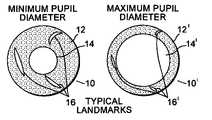
- FIG. 1is an illustration of two iris images having a constricted pupil and a dilated pupil, respectively, showing the change in form, position and size of naturally occurring landmarks at the two pupil diameter extremes;
- FIG. 2schematically shows three sequential iris images having varying pupil diameters and the respective iris landmarks
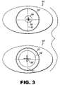
- FIG. 3schematically illustrates pupil center displacement with respect to a limbal reference as a function of different pupil sizes.
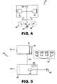
- FIG. 4is a schematic illustration of a device according to an embodiment of the invention.
- FIG. 5is a schematic illustration of a system according to an embodiment of the invention.
- the inventionis directed to methods and systems providing alignment between diagnostic images of the eye and treatment images of the eye that result in greater accuracy of the laser treatment and, therefore, greater patient satisfaction.
- FIGS. 1 and 2An embodiment of the invention is described below in accordance with FIGS. 1 and 2 .
- Systems and deviceswhich use iris pattern recognition for identifying eye structures and for aligning diagnostic and therapeutic images for eye surgery.
- PCT/EP00/10373discusses systems and methods for alignment and photorefractive treatment of an eye in which a diagnostic iris image identified with artificial markers is obtained by a camera system along with a refractive diagnostic measurement.
- a computer system linked to the laser treatment systemthen uses this iris image information to develop and align the photorefractive treatment.
- FIG. 1schematically shows two sequential iris images 10 ′, 10 .
- Image 10shows an iris area 12 , a constricted pupil 14 and typical iris landmarks 16 .
- constricted pupilrefers to a substantially small pupil size caused by bright light conditions, e.g., eye tracker and fixation light sources along with other environmental conditions present during the treatment phase of laser eye surgery that cause the pupil to constrict.
- the term constricted pupiltherefore, is not intended to merely describe the smallest possible pupil size that can be induced in a patient's eye, but to describe the smallest working pupil size in accordance with the invention.
- Iris image 10 ′shows the same iris 12 ′, however the pupil 14 ′ is dilated and the iris landmarks 16 ′ are shown somewhat obscured due to the dilation of the pupil with respect to iris image 10 .
- the dilated pupil 14 ′is due to low light conditions typically associated with diagnostic measurement of the eye, for example, when a wavefront measuring device such as a ZywaveTM (Bausch & Lomb/Technolas, Kunststoff, Germany) wavefront measuring device or an Orbscan II® (Orbtek, Salt Lake City, Utah) corneal topographer is used to obtain wavefront aberration information.
- a wavefront measuring devicesuch as a ZywaveTM (Bausch & Lomb/Technolas, Kunststoff, Germany) wavefront measuring device or an Orbscan II® (Orbtek, Salt Lake City, Utah) corneal topographer is used to obtain wavefront aberration information.
- the term “dilated pupil”is not intended to refer merely to a maximally dilated pupil that is chemically or artificially induced, but rather to a dark adapted pupil, which is the largest working pupil size associated with this invention.
- the iris images 10 , 10 ′ in FIG. 1are intended to illustrate the changes in form, position and size of naturally occurring landmarks 16 , 16 ′ when pupil size changes dramatically (e.g., from dilated to constricted). Under these circumstances, current iris pattern recognition technology has fallen short of being able to match landmark 16 in the constricted pupil condition with landmark 16 ′ in the dilated pupil condition. Therefore, artificial markers on the eye have been used as in tracking points.
- Wavefront measurementsare typically centered about the patient's visual axis or about the center of the patient's dilated pupil. It is advantageous to measure the wavefront aberration over the dilated pupil because certain higher order aberrations manifest their vision compromising effects when the pupil is dark adapted (e.g., night time vision).
- Iris image 10 ′schematically shows the patient's iris image during diagnostic measurement, having a dilated pupil 14 ′ and iris landmarks 16 ′.
- a diagnostic iris image 10 ′is obtained by a diagnostic iris image capture device with the image 10 ′ corresponding to the pupil diameter during the diagnostic evaluation.
- the visible illumination levelis increased, causing a corresponding decrease in pupil diameter illustrated by 14 ′′ in iris image 10 ′′.
- Iris landmarks 16 ′′are also visible having undergone a lesser change than shown in images 10 ′, 10 of FIG. 1 .
- diagnostic iris image 10shows a constricted pupil 14 and iris landmarks 16 which, again, have undergone a small and detectable change from landmarks 16 ′′ in iris image 10 ′′.
- the pupil diameter 14 shown in diagnostic iris image 10will substantially correspond to the pupil diameter of a treatment iris image obtained by a treatment iris image capture device during the treatment phase of the laser vision correction surgery.
- Diagnostic iris image processing hardware and softwarecan now track the changes in the sequential set of iris images 10 ′, 10 ′′, 10 by tracking the landmark indicia so that the iris image 10 ′ associated with the dilated diagnostic pupil 14 ′ can be aligned with the iris image 10 associated with the constricted diagnostic pupil 14 .
- Iris image processing hardware and software connected to a treatment part of the laser systemis now used to align a treatment iris image, substantially represented by iris image 10 in FIG. 2 , with the exported diagnostic iris image 10 , allowing the laser ablation treatment pattern directed to the constricted treatment pupil to be accurately aligned with respect to the diagnostic iris image associated with the dilated diagnostic pupil.
- An advantage of this embodiment wherein the diagnostic iris images are sorted and aligned by the diagnostic stage processingresults in the limited data transfer of a single image from the diagnostic phase to the treatment phase.
- the alignment method according to the inventionprovides appropriate information for rotating the laser ablation treatment pattern to correspond to the cyclo-rotation of the eye.
- a diagnostic measurement of the patient's eye in the dilated pupil conditionis obtained in addition to the diagnostic iris images with the dilated through constricted pupil.
- the image acquiring apparatus and the diagnostic measurement devicemay be separate devices, or, these functions may be integrated into a single device.
- a diagnostic measurementwill be used by the treatment laser system to calculate the appropriate ablation profile for vision correction. Therefore, it is preferable that the dilated diagnostic measurement be simultaneously associated with the dilated pupil diagnostic iris image.
- the diagnostic measurementitself will advantageously include the patient's wavefront aberration information which can be directly obtained by a variety of wavefront sensor instruments.
- One such deviceis the Zywave wavefront analyzer (Bausch & Lomb/Technolas) which incorporates a Hartmann-Shack wavefront sensor.
- Other types of devicessuch as elevation based topographers with ray trace capability such as, e.g., Orbscan II® corneal topography device (Bausch & Lomb/Orbtek, Salt Lake City, Utah) can provide measurement data from which wavefront aberration information can be derived.
- the diagnostic measurementalso preferably includes a measure of the astigmatism.
- the entire plurality of diagnostic iris imagescan be exported to the treatment stage processor where the diagnostic iris images can be sorted and appropriately aligned for correlation with the treatment iris image.
- This aspectwould allow tracking and alignment of the treatment iris image in real time with a corresponding diagnostic iris image during the course of surgery. Due to the volume of information being transported between the diagnostic image processor and the treatment image processor, considerably more processing power may be required than for an alternative aspect in which the sorting and alignment of the dilated pupil and constricted pupil iris images is performed by a diagnostic image processor which then exports the aligned constricted pupil image to the treatment image processor for correlation and alignment with the treatment iris image. In this aspect, the computing power requirement is reduced at the expense of a static image comparison with the treatment iris image. A variety of factors will ultimately determine which aspect is preferred by the practitioner.
- a diagnostic image 30 ‘of the patient’s eye having a dilated pupil 34 ′is obtained.
- a center location 36 ′ of the dilated pupil 34 ′is determined with respect to an illumination independent eye landmark, preferably an edge of the limbus 32 of the patient's eye.
- Algorithms and mathematical means for calculating a center location of a pupil with respect to a radial reference pointare well known by persons skilled in the art and require no explanation for carrying out the invention.
- a selected amount of visible illuminationis directed to the eye to constrict the pupil as shown in eye image 30 by pupil 34 .
- the center location 36 of the constricted pupil 34is determined with respect to the eye landmark 32 which is the same as eye landmark 32 in image 30 ′.
- the limbal edgeprovides an advantageous reference point because the limbus is substantially unaffected by changes in pupil size.
- the vector displacement of the dilated pupil center 36 ′ and the constricted pupil center 36is determined by techniques well known to those skilled in the art.
- This vector displacementis then used to adjust the position of a calculated laser ablation treatment profile to be applied to the eye having a constricted pupil based upon diagnostic wavefront information obtained from the diagnostic image of the eye having a dilated pupil. It is advantageous to obtain the diagnostic images of the patient's eye and the measurement of the displacement of the center location of the pupil in infra red light so that pupil size does not change during this data acquisition. Once the vector displacement of the pupil centers is determined, this information can be saved in a treatment file of a controller of a treatment laser for use at an appropriate time.
- device 40is an aberrometer such as that described in Williams id, for obtaining a wavefront aberration measurement of a patient's eye 42 .
- An iris 41 and a pupil 43 of the eye 42are also shown.
- the aberrometer 40typically contains an IR camera 44 for obtaining diagnostic images such as those schematically shown in FIGS. 1 and 2 , a wavefront sensor and associated optics and electronics schematically represented by numeral 46 in FIG. 4 , and a fixed illumination level fixation target 48 used for alignment purposes as well understood by those skilled in the art.
- the improvementcomprises replacing fixed illumination fixation target 48 with a variably controllable visible illumination fixation target so that the diameter of the pupil 43 of the patient's eye can be changed to obtain the diagnostic iris images as described herein above.
- the controllable visible illumination sourcecan be externally associated with the device 40 as represented by controllable visible illumination sources 49 .
- the device 40could be a corneal topographer such as an Orbscan II device adapted with a controllable visible illumination source as described herein.
- device 40could be a pupilometer typically including a controllable visible illumination source for pupil diameter control with the improvement according to the invention being a wavefront sensing component or other known hardware and software components that would provide wavefront aberration information about the eye under examination.
- the system 50is a diagnostic and therapeutic system for laser eye surgery that includes a diagnostic part 52 and a laser treatment part 54 .
- the diagnostic part 52includes a diagnostic instrument 40 as described with respect to FIG. 4 and a diagnostic processor 56 that is programmed to sort, correlate and align the diagnostic iris images as represented in 58 .
- An ultimately aligned constricted pupil diagnostic iris image(as described herein above) is exported from diagnostic part 52 as illustrated by reference 59 via any variety of well-known image data transfer means including land based and wireless communications, computer storage media such as disk or CD, via the Internet or other networks, etc., to laser treatment part 54 .
- Laser treatment part 54includes a treatment iris image capture device 64 for obtaining the treatment iris image having a constricted pupil of eye 42 ′, a treatment laser 62 and other components such as an eye tracker (not shown).
- the entire plurality of diagnostic iris images as represented at 58is exported to treatment part 54 where processing hardware and software represented by processor 66 sorts and correlates the diagnostic iris images and provides the appropriate alignment between the constricted pupil treatment image and the corresponding constricted pupil diagnostic iris image.
- Processor 66may also control the calculated laser ablation pattern in response to the iris pattern recognition alignment.
- processor 56 in the diagnostic part 52 and a processor 66 in the treatment part 54it may be preferable to have a processor 56 in the diagnostic part 52 and a processor 66 in the treatment part 54 , however the nature and location of the processing hardware and software will be determined by surgeon preference and available iris recognition software and hardware components.
- the processor 56 associated with diagnostic instrument 40is adapted to calculate a vector displacement of the pupil center between the dilated pupil diagnostic image and the constricted pupil diagnostic image. This information is likewise exported to the laser treatment part of the system 54 to be used for translationally adjusting the laser treatment pattern on the treatment eye which has a constricted pupil.
- a patientis seated and aligned with respect to a diagnostic device (e.g., aberrometer) that can provide a diagnostic wavefront measurement of the patient's eye and which can acquire and process diagnostic iris images.
- the patient's eyeis aligned in respect f the aberrometer with the use of a low level visible illumination fixation target such that the patient's dark adapted pupil diameter might be in the range of 6 to 7 mm.
- Both a diagnostic wavefront measurement and a dilated pupil diagnostic iris imageare obtained at this point.
- the brightness of the fixation targetis then increased until the patient's pupil diameter decreases to about 5 mm.
- Another diagnostic iris imageis obtained and stored.
- the illumination level of the fixation targetis sequentially increased so that diagnostic iris images may be obtained at various pupil sizes until a constricted pupil (e.g., about 2 mm.) diagnostic iris image is obtained.
- a pupil center shiftis also calculated in the form of a vector displacement for the dilated pupil diagnostic iris image and the constricted pupil diagnostic iris image through limbal edge detection.
- Processing hardware and software associated either with the diagnostic system and/or the treatment systemtracks an iris recognition landmark through the different pupil sized diagnostic iris images to ultimately align the dilated pupil diagnostic image with the constricted pupil diagnostic iris image.
- An ablation profileis generated based upon the diagnostic measurement associated with the dilated pupil.
- the rotational alignment and vector displacement datais also made available to the treatment laser system.
- the patientis positioned (supine) under the treatment system and a real time image of the actual constricted pupil/iris is obtained.
- This treatment iris imageis then aligned with the substantially corresponding diagnostic iris image having generally the same pupil size via the identified iris recognition landmark, so that the calculated ablation treatment can be rotated, translated and otherwise adjusted to provide a more accurate treatment.
- the limbus based pupil center displacementcan be used at a minimum to eliminate decentration in spite of uncorrected rotation.
Landscapes
- Health & Medical Sciences (AREA)
- Life Sciences & Earth Sciences (AREA)
- Engineering & Computer Science (AREA)
- General Health & Medical Sciences (AREA)
- Physics & Mathematics (AREA)
- Surgery (AREA)
- Veterinary Medicine (AREA)
- Heart & Thoracic Surgery (AREA)
- Medical Informatics (AREA)
- Molecular Biology (AREA)
- Ophthalmology & Optometry (AREA)
- Animal Behavior & Ethology (AREA)
- Biophysics (AREA)
- Public Health (AREA)
- Biomedical Technology (AREA)
- Human Computer Interaction (AREA)
- General Physics & Mathematics (AREA)
- Multimedia (AREA)
- Theoretical Computer Science (AREA)
- Pathology (AREA)
- Eye Examination Apparatus (AREA)
- Laser Surgery Devices (AREA)
- Radiation-Therapy Devices (AREA)
Abstract
Description
Claims (28)
Priority Applications (2)
| Application Number | Priority Date | Filing Date | Title |
|---|---|---|---|
| US10/474,958US7331667B2 (en) | 2001-04-27 | 2001-05-10 | Iris pattern recognition and alignment |
| US12/024,415US8186830B2 (en) | 2001-04-27 | 2008-02-01 | Iris pattern recognition and alignment |
Applications Claiming Priority (3)
| Application Number | Priority Date | Filing Date | Title |
|---|---|---|---|
| US28695401P | 2001-04-27 | 2001-04-27 | |
| PCT/EP2001/005354WO2002087442A1 (en) | 2001-04-27 | 2001-05-10 | Iris pattern recognition and alignment |
| US10/474,958US7331667B2 (en) | 2001-04-27 | 2001-05-10 | Iris pattern recognition and alignment |
Related Child Applications (1)
| Application Number | Title | Priority Date | Filing Date |
|---|---|---|---|
| US12/024,415DivisionUS8186830B2 (en) | 2001-04-27 | 2008-02-01 | Iris pattern recognition and alignment |
Publications (2)
| Publication Number | Publication Date |
|---|---|
| US20040169817A1 US20040169817A1 (en) | 2004-09-02 |
| US7331667B2true US7331667B2 (en) | 2008-02-19 |
Family
ID=23100851
Family Applications (2)
| Application Number | Title | Priority Date | Filing Date |
|---|---|---|---|
| US10/474,958Expired - LifetimeUS7331667B2 (en) | 2001-04-27 | 2001-05-10 | Iris pattern recognition and alignment |
| US12/024,415Expired - Fee RelatedUS8186830B2 (en) | 2001-04-27 | 2008-02-01 | Iris pattern recognition and alignment |
Family Applications After (1)
| Application Number | Title | Priority Date | Filing Date |
|---|---|---|---|
| US12/024,415Expired - Fee RelatedUS8186830B2 (en) | 2001-04-27 | 2008-02-01 | Iris pattern recognition and alignment |
Country Status (12)
| Country | Link |
|---|---|
| US (2) | US7331667B2 (en) |
| EP (1) | EP1383429B1 (en) |
| JP (2) | JP2004534569A (en) |
| KR (1) | KR100897365B1 (en) |
| CN (1) | CN100502777C (en) |
| AU (1) | AU2001297967B2 (en) |
| BR (1) | BR0116991B1 (en) |
| CA (1) | CA2444961C (en) |
| DE (2) | DE01274188T1 (en) |
| ES (1) | ES2214164T3 (en) |
| SG (1) | SG161097A1 (en) |
| WO (1) | WO2002087442A1 (en) |
Cited By (33)
| Publication number | Priority date | Publication date | Assignee | Title |
|---|---|---|---|---|
| US20070274570A1 (en)* | 2005-01-26 | 2007-11-29 | Honeywell International Inc. | Iris recognition system having image quality metrics |
| US20090318911A1 (en)* | 2006-09-12 | 2009-12-24 | Shalesh Kaushal | Devices and Methods for Computer-Assisted Surgery |
| US20090318773A1 (en)* | 2008-06-24 | 2009-12-24 | Searete Llc, A Limited Liability Corporation Of The State Of Delaware | Involuntary-response-dependent consequences |
| US20100002913A1 (en)* | 2005-01-26 | 2010-01-07 | Honeywell International Inc. | distance iris recognition |
| US20100030696A1 (en)* | 2006-08-22 | 2010-02-04 | David Naccache | Biometric electronic payment terminal and transaction method |
| US20100052898A1 (en)* | 2008-08-27 | 2010-03-04 | Searete Llc, A Limited Liability Corporation Of The State Of Delaware | Health-related signaling via wearable items |
| US20100056873A1 (en)* | 2008-08-27 | 2010-03-04 | Allen Paul G | Health-related signaling via wearable items |
| US20100052897A1 (en)* | 2008-08-27 | 2010-03-04 | Allen Paul G | Health-related signaling via wearable items |
| US20100052892A1 (en)* | 2008-08-27 | 2010-03-04 | Searete Llc, A Limited Liability Corporation Of The State Of Delaware | Health-related signaling via wearable items |
| US20100094262A1 (en)* | 2008-10-10 | 2010-04-15 | Ashok Burton Tripathi | Real-time surgical reference indicium apparatus and methods for surgical applications |
| US20100182440A1 (en)* | 2008-05-09 | 2010-07-22 | Honeywell International Inc. | Heterogeneous video capturing system |
| US20100208199A1 (en)* | 2009-02-19 | 2010-08-19 | Ilias Levis | Intraocular lens alignment |
| US20100217278A1 (en)* | 2009-02-20 | 2010-08-26 | Ashok Burton Tripathi | Real-time surgical reference indicium apparatus and methods for intraocular lens implantation |
| US20110075892A1 (en)* | 2009-09-25 | 2011-03-31 | International Business Machines Corporation | System and method for generating and employing short length iris codes |
| US20110187845A1 (en)* | 2006-03-03 | 2011-08-04 | Honeywell International Inc. | System for iris detection, tracking and recognition at a distance |
| US20110292340A1 (en)* | 2010-05-31 | 2011-12-01 | Nidek Co., Ltd. | Ophthalmic apparatus |
| US8284046B2 (en) | 2008-08-27 | 2012-10-09 | The Invention Science Fund I, Llc | Health-related signaling via wearable items |
| US8317776B2 (en) | 2007-12-18 | 2012-11-27 | The Invention Science Fund I, Llc | Circulatory monitoring systems and methods |
| US20130060241A1 (en)* | 2010-04-27 | 2013-03-07 | Daniel S. Haddad | Dynamic real time active pupil centroid compensation |
| US8409132B2 (en) | 2007-12-18 | 2013-04-02 | The Invention Science Fund I, Llc | Treatment indications informed by a priori implant information |
| US8452131B2 (en) | 2009-09-25 | 2013-05-28 | International Business Machines Corporation | Iris recognition system and method |
| US8472681B2 (en) | 2009-06-15 | 2013-06-25 | Honeywell International Inc. | Iris and ocular recognition system using trace transforms |
| US8630464B2 (en) | 2009-06-15 | 2014-01-14 | Honeywell International Inc. | Adaptive iris matching using database indexing |
| US8636670B2 (en) | 2008-05-13 | 2014-01-28 | The Invention Science Fund I, Llc | Circulatory monitoring systems and methods |
| US8742887B2 (en) | 2010-09-03 | 2014-06-03 | Honeywell International Inc. | Biometric visitor check system |
| US9552660B2 (en) | 2012-08-30 | 2017-01-24 | Truevision Systems, Inc. | Imaging system and methods displaying a fused multidimensional reconstructed image |
| US9655775B2 (en) | 2007-08-13 | 2017-05-23 | Novartis Ag | Toric lenses alignment using pre-operative images |
| US10117721B2 (en) | 2008-10-10 | 2018-11-06 | Truevision Systems, Inc. | Real-time surgical reference guides and methods for surgical applications |
| US10299880B2 (en) | 2017-04-24 | 2019-05-28 | Truevision Systems, Inc. | Stereoscopic visualization camera and platform |
| US10398598B2 (en) | 2008-04-04 | 2019-09-03 | Truevision Systems, Inc. | Apparatus and methods for performing enhanced visually directed procedures under low ambient light conditions |
| US10917543B2 (en) | 2017-04-24 | 2021-02-09 | Alcon Inc. | Stereoscopic visualization camera and integrated robotics platform |
| US11083537B2 (en) | 2017-04-24 | 2021-08-10 | Alcon Inc. | Stereoscopic camera with fluorescence visualization |
| EP4226845A1 (en) | 2022-02-11 | 2023-08-16 | Ziemer Ophthalmic Systems AG | Eye image quality analysis |
Families Citing this family (67)
| Publication number | Priority date | Publication date | Assignee | Title |
|---|---|---|---|---|
| CA2712321C (en) | 1999-10-21 | 2013-07-30 | Technolas Gmbh Ophthalmologische Systeme | Iris recognition and tracking for optical treatment |
| US7431455B2 (en)* | 2005-03-22 | 2008-10-07 | Amo Manufacturing Usa, Llc | Pupilometer for pupil center drift and pupil size measurements at differing viewing distances |
| JP3978024B2 (en)* | 2001-12-03 | 2007-09-19 | 株式会社ニデック | Ophthalmic device and corneal surgery device |
| EP1516156B1 (en) | 2002-05-30 | 2019-10-23 | AMO Manufacturing USA, LLC | Tracking torsional eye orientation and position |
| ES2253139T3 (en)* | 2003-04-11 | 2011-07-06 | BAUSCH & LOMB INCORPORATED | SYSTEM AND METHOD FOR ACQUIRING DATA FROM ONE EYE. |
| US7458683B2 (en) | 2003-06-16 | 2008-12-02 | Amo Manufacturing Usa, Llc | Methods and devices for registering optical measurement datasets of an optical system |
| US8705808B2 (en) | 2003-09-05 | 2014-04-22 | Honeywell International Inc. | Combined face and iris recognition system |
| US8098901B2 (en) | 2005-01-26 | 2012-01-17 | Honeywell International Inc. | Standoff iris recognition system |
| US7761453B2 (en) | 2005-01-26 | 2010-07-20 | Honeywell International Inc. | Method and system for indexing and searching an iris image database |
| US8090157B2 (en) | 2005-01-26 | 2012-01-03 | Honeywell International Inc. | Approaches and apparatus for eye detection in a digital image |
| US8442276B2 (en) | 2006-03-03 | 2013-05-14 | Honeywell International Inc. | Invariant radial iris segmentation |
| DE112004002612T5 (en)* | 2004-01-09 | 2006-11-09 | Customvis Plc, Balcatta | Limbus-based tracking of eye movements |
| US7481536B2 (en)* | 2004-02-19 | 2009-01-27 | Amo Manufacturing Usa, Llc | Methods and systems for differentiating left and right eye images |
| US7341345B2 (en) | 2004-07-19 | 2008-03-11 | Massachusetts Eye & Ear Infirmary | Ocular wavefront-correction profiling |
| US7614743B2 (en)* | 2004-07-20 | 2009-11-10 | Medtronic, Inc. | Vital signs monitoring system with wireless pupilometer interface |
| US7815631B2 (en)* | 2004-11-30 | 2010-10-19 | Alcon Refractivehorizons, Inc. | Eye registration system for refractive surgery and associated methods |
| US7934833B2 (en) | 2005-12-22 | 2011-05-03 | Alcon Refractivehorizons, Inc. | Image alignment system for use in laser ablation treatment of the cornea |
| WO2008019169A2 (en) | 2006-03-03 | 2008-02-14 | Honeywell International, Inc. | Iris encoding system |
| WO2007101275A1 (en) | 2006-03-03 | 2007-09-07 | Honeywell International, Inc. | Camera with auto-focus capability |
| WO2007101276A1 (en) | 2006-03-03 | 2007-09-07 | Honeywell International, Inc. | Single lens splitter camera |
| AU2007281940B2 (en) | 2006-03-03 | 2010-12-16 | Gentex Corporation | Modular biometrics collection system architecture |
| US8025399B2 (en)* | 2007-01-26 | 2011-09-27 | Aoptix Technologies, Inc. | Combined iris imager and wavefront sensor |
| US8092021B1 (en) | 2007-01-26 | 2012-01-10 | Aoptix Technologies, Inc. | On-axis illumination for iris imaging |
| US20080187213A1 (en)* | 2007-02-06 | 2008-08-07 | Microsoft Corporation | Fast Landmark Detection Using Regression Methods |
| US8063889B2 (en) | 2007-04-25 | 2011-11-22 | Honeywell International Inc. | Biometric data collection system |
| US8111942B2 (en)* | 2008-02-06 | 2012-02-07 | O2Micro, Inc. | System and method for optimizing camera settings |
| US8213782B2 (en) | 2008-08-07 | 2012-07-03 | Honeywell International Inc. | Predictive autofocusing system |
| US8090246B2 (en) | 2008-08-08 | 2012-01-03 | Honeywell International Inc. | Image acquisition system |
| CN102186406B (en)* | 2008-10-15 | 2014-10-22 | 欧普蒂布兰德有限责任公司 | Method and apparatus for obtaining an image of an ocular feature |
| US8280119B2 (en) | 2008-12-05 | 2012-10-02 | Honeywell International Inc. | Iris recognition system using quality metrics |
| DE102009030466A1 (en)* | 2009-06-23 | 2011-01-05 | Carl Zeiss Meditec Ag | Method and device for aligning location-related eye data |
| CA2786677C (en)* | 2010-01-22 | 2016-07-12 | Iritech Inc. | Device and method for iris recognition using a plurality of iris images having different iris sizes |
| US11771596B2 (en) | 2010-05-10 | 2023-10-03 | Ramot At Tel-Aviv University Ltd. | System and method for treating an eye |
| US9053562B1 (en) | 2010-06-24 | 2015-06-09 | Gregory S. Rabin | Two dimensional to three dimensional moving image converter |
| WO2012040196A1 (en)* | 2010-09-20 | 2012-03-29 | Amo Development Llc | System and methods for mitigating changes in pupil size during laser refractive surgery to maintain ablation centration |
| GB2495323B (en) | 2011-10-07 | 2018-05-30 | Irisguard Inc | Improvements for iris recognition systems |
| GB2495324B (en) | 2011-10-07 | 2018-05-30 | Irisguard Inc | Security improvements for Iris recognition systems |
| GB2495328B (en)* | 2011-10-07 | 2018-05-30 | Irisguard Inc | Improvements relating to Iris cameras |
| KR102023611B1 (en)* | 2012-05-04 | 2019-09-23 | 삼성전자 주식회사 | Terminal and method for iris scanning and proximity sensing |
| EP2749204B1 (en) | 2012-12-28 | 2016-03-16 | Canon Kabushiki Kaisha | Image processing apparatus and image processing method |
| US9992021B1 (en) | 2013-03-14 | 2018-06-05 | GoTenna, Inc. | System and method for private and point-to-point communication between computing devices |
| JP6236882B2 (en)* | 2013-06-03 | 2017-11-29 | 株式会社ニデック | Laser therapy device |
| TW201513827A (en)* | 2013-10-04 | 2015-04-16 | Univ Nat Chiao Tung | Portable pupil detecting device of multi-band stimulating light and infrared ray's illumination |
| EP3220861B1 (en)* | 2014-11-20 | 2021-03-24 | Alcon Inc. | An apparatus for laser processing an eye |
| IL243384A (en)* | 2015-12-28 | 2017-05-29 | Schneider Ron | System and method for determining the position and orientation of a tool tip relative to eye tissue of interest |
| US11484363B2 (en) | 2015-12-28 | 2022-11-01 | Elbit Systems Ltd. | System and method for determining the position and orientation of a tool tip relative to eye tissue of interest |
| EP3451898B1 (en) | 2016-05-02 | 2023-06-21 | Alcon Inc. | Overlay imaging for registration of a patient eye for laser surgery |
| CA3029876A1 (en)* | 2016-07-06 | 2018-01-11 | Amo Wavefront Sciences, Llc | Retinal imaging for reference during laser eye surgery |
| US10925479B2 (en)* | 2016-10-13 | 2021-02-23 | Ronald Michael Kurtz | Networked system of mobile communication platforms for nonpharmacologic constriction of a pupil |
| US10524655B2 (en) | 2017-09-27 | 2020-01-07 | International Business Machines Corporation | Ophthalmoscope using natural pupil dilation |
| WO2019116078A1 (en)* | 2017-12-13 | 2019-06-20 | Medical Diagnostech (Pty) Ltd | System and method for obtaining a pupil response profile |
| EP3561446A1 (en)* | 2018-04-23 | 2019-10-30 | Carl Zeiss Vision International GmbH | Method and device for measuring an optical lens for individual wear situations of a user |
| CN112352170B (en)* | 2018-05-15 | 2024-08-23 | 鲍希与洛姆伯股份有限公司 | Water extractable ophthalmic device |
| IL308110A (en) | 2018-07-02 | 2023-12-01 | Belkin Vision Ltd | Direct selective laser trabeculoplasty |
| ES3005558T3 (en)* | 2018-07-03 | 2025-03-14 | Bausch & Lomb | Water extractable ophthalmic devices |
| JP7357055B2 (en)* | 2018-08-10 | 2023-10-05 | ボシュ・アンド・ロム・インコーポレイテッド | High water content ophthalmic device |
| CA3107771A1 (en)* | 2018-08-10 | 2020-02-13 | Bausch & Lomb Incorporated | Ophthalmic devices |
| JP7448973B2 (en) | 2018-10-28 | 2024-03-13 | ベルキン ヴィジョン リミテッド | Direct selective laser trabeculoplasty protection |
| WO2020183342A1 (en)* | 2019-03-13 | 2020-09-17 | Belkin Laser Ltd. | Automated laser iridotomy |
| CN111832344B (en)* | 2019-04-17 | 2023-10-24 | 深圳熙卓科技有限公司 | Dynamic pupil detection method and device |
| WO2021044540A1 (en) | 2019-09-04 | 2021-03-11 | 日本電気株式会社 | Control device, control method, and storage medium |
| JP7391586B2 (en)* | 2019-09-27 | 2023-12-05 | 株式会社トプコン | ophthalmology system |
| CN112043235B (en)* | 2020-07-13 | 2024-02-06 | 天津市眼科医院 | Portable eyeball static rotation measuring instrument and method for measuring eyeball rotation angle by utilizing same |
| WO2022018525A1 (en) | 2020-07-19 | 2022-01-27 | Belkin Vision Ltd. | Automated capsulotomy |
| CN114099985B (en)* | 2021-11-29 | 2024-01-26 | 苏州宣嘉光电科技有限公司 | Device for adjusting light source module by recognizing image characteristics |
| CN114494824B (en)* | 2021-12-30 | 2022-11-22 | 北京城市网邻信息技术有限公司 | Target detection method, device and equipment for panoramic image and storage medium |
| CN117338513A (en)* | 2023-07-28 | 2024-01-05 | 武汉安顿医疗技术有限责任公司 | A central positioning system and method for femtosecond laser ophthalmic corneal refractive surgery |
Citations (3)
| Publication number | Priority date | Publication date | Assignee | Title |
|---|---|---|---|---|
| US5740803A (en)* | 1997-03-07 | 1998-04-21 | Autonomous Technologies Corporation | Locating the center of the entrance pupil of an eye after pupil dilation |
| US6247813B1 (en)* | 1999-04-09 | 2001-06-19 | Iritech, Inc. | Iris identification system and method of identifying a person through iris recognition |
| US7146983B1 (en)* | 1999-10-21 | 2006-12-12 | Kristian Hohla | Iris recognition and tracking for optical treatment |
Family Cites Families (13)
| Publication number | Priority date | Publication date | Assignee | Title |
|---|---|---|---|---|
| US4641347A (en)* | 1983-07-18 | 1987-02-03 | Pitney Bowes Inc. | System for printing encrypted messages with a character generator and bar-code representation |
| US4641349A (en)* | 1985-02-20 | 1987-02-03 | Leonard Flom | Iris recognition system |
| US5258791A (en)* | 1990-07-24 | 1993-11-02 | General Electric Company | Spatially resolved objective autorefractometer |
| US5220361A (en) | 1991-06-05 | 1993-06-15 | Allergan Humphrey | Gaze tracking for field analyzer |
| AU716040B2 (en)* | 1993-06-24 | 2000-02-17 | Bausch & Lomb Incorporated | Ophthalmic pachymeter and method of making ophthalmic determinations |
| JP3490520B2 (en)* | 1994-12-12 | 2004-01-26 | 株式会社ニデック | Ophthalmic equipment |
| US5777719A (en)* | 1996-12-23 | 1998-07-07 | University Of Rochester | Method and apparatus for improving vision and the resolution of retinal images |
| US6820979B1 (en)* | 1999-04-23 | 2004-11-23 | Neuroptics, Inc. | Pupilometer with pupil irregularity detection, pupil tracking, and pupil response detection capability, glaucoma screening capability, intracranial pressure detection capability, and ocular aberration measurement capability |
| DE19950792A1 (en) | 1999-10-21 | 2001-04-26 | Technolas Gmbh | Ophthalmic wavefront aberration diagnostic tool, has camera that aids in focusing aerial image from lenslet array, on wavefront sensor |
| CN101023860B (en) | 1999-10-21 | 2010-06-16 | 泰克诺拉斯眼科系统有限公司 | Customized corneal profiling |
| CN1423546A (en)* | 1999-12-29 | 2003-06-11 | 新英格兰验光学院 | Myopia progression retardation by optical defect correction |
| EP1210002B1 (en) | 2000-04-19 | 2007-12-12 | Alcon RefractiveHorizons, Inc. | Eye registration control method |
| JP4649035B2 (en) | 2000-10-18 | 2011-03-09 | 株式会社トプコン | Eye characteristics measuring device |
- 2001
- 2001-05-10ESES01274188Tpatent/ES2214164T3/ennot_activeExpired - Lifetime
- 2001-05-10KRKR1020037014084Apatent/KR100897365B1/ennot_activeExpired - Fee Related
- 2001-05-10JPJP2002584797Apatent/JP2004534569A/enactivePending
- 2001-05-10WOPCT/EP2001/005354patent/WO2002087442A1/enactiveIP Right Grant
- 2001-05-10DEDE0001383429Tpatent/DE01274188T1/enactivePending
- 2001-05-10EPEP01274188Apatent/EP1383429B1/ennot_activeExpired - Lifetime
- 2001-05-10CNCNB01823187XApatent/CN100502777C/ennot_activeExpired - Lifetime
- 2001-05-10AUAU2001297967Apatent/AU2001297967B2/ennot_activeCeased
- 2001-05-10SGSG200508502-2Apatent/SG161097A1/enunknown
- 2001-05-10USUS10/474,958patent/US7331667B2/ennot_activeExpired - Lifetime
- 2001-05-10BRBRPI0116991-2Apatent/BR0116991B1/ennot_activeIP Right Cessation
- 2001-05-10CACA2444961Apatent/CA2444961C/ennot_activeExpired - Lifetime
- 2001-05-10DEDE60135879Tpatent/DE60135879D1/ennot_activeExpired - Lifetime
- 2007
- 2007-04-17JPJP2007108754Apatent/JP2007268285A/enactivePending
- 2008
- 2008-02-01USUS12/024,415patent/US8186830B2/ennot_activeExpired - Fee Related
Patent Citations (3)
| Publication number | Priority date | Publication date | Assignee | Title |
|---|---|---|---|---|
| US5740803A (en)* | 1997-03-07 | 1998-04-21 | Autonomous Technologies Corporation | Locating the center of the entrance pupil of an eye after pupil dilation |
| US6247813B1 (en)* | 1999-04-09 | 2001-06-19 | Iritech, Inc. | Iris identification system and method of identifying a person through iris recognition |
| US7146983B1 (en)* | 1999-10-21 | 2006-12-12 | Kristian Hohla | Iris recognition and tracking for optical treatment |
Cited By (60)
| Publication number | Priority date | Publication date | Assignee | Title |
|---|---|---|---|---|
| US20070274570A1 (en)* | 2005-01-26 | 2007-11-29 | Honeywell International Inc. | Iris recognition system having image quality metrics |
| US20100002913A1 (en)* | 2005-01-26 | 2010-01-07 | Honeywell International Inc. | distance iris recognition |
| US8285005B2 (en) | 2005-01-26 | 2012-10-09 | Honeywell International Inc. | Distance iris recognition |
| US8050463B2 (en)* | 2005-01-26 | 2011-11-01 | Honeywell International Inc. | Iris recognition system having image quality metrics |
| US20110187845A1 (en)* | 2006-03-03 | 2011-08-04 | Honeywell International Inc. | System for iris detection, tracking and recognition at a distance |
| US8761458B2 (en) | 2006-03-03 | 2014-06-24 | Honeywell International Inc. | System for iris detection, tracking and recognition at a distance |
| US20100030696A1 (en)* | 2006-08-22 | 2010-02-04 | David Naccache | Biometric electronic payment terminal and transaction method |
| US20090318911A1 (en)* | 2006-09-12 | 2009-12-24 | Shalesh Kaushal | Devices and Methods for Computer-Assisted Surgery |
| US8512323B2 (en) | 2006-09-12 | 2013-08-20 | University Of Florida Research Foundation, Inc. | Devices and methods for computer-assisted surgery |
| US9655775B2 (en) | 2007-08-13 | 2017-05-23 | Novartis Ag | Toric lenses alignment using pre-operative images |
| US9717896B2 (en) | 2007-12-18 | 2017-08-01 | Gearbox, Llc | Treatment indications informed by a priori implant information |
| US8317776B2 (en) | 2007-12-18 | 2012-11-27 | The Invention Science Fund I, Llc | Circulatory monitoring systems and methods |
| US8870813B2 (en) | 2007-12-18 | 2014-10-28 | The Invention Science Fund I, Llc | Circulatory monitoring systems and methods |
| US8409132B2 (en) | 2007-12-18 | 2013-04-02 | The Invention Science Fund I, Llc | Treatment indications informed by a priori implant information |
| US8403881B2 (en) | 2007-12-18 | 2013-03-26 | The Invention Science Fund I, Llc | Circulatory monitoring systems and methods |
| US10398598B2 (en) | 2008-04-04 | 2019-09-03 | Truevision Systems, Inc. | Apparatus and methods for performing enhanced visually directed procedures under low ambient light conditions |
| US20100182440A1 (en)* | 2008-05-09 | 2010-07-22 | Honeywell International Inc. | Heterogeneous video capturing system |
| US8436907B2 (en) | 2008-05-09 | 2013-05-07 | Honeywell International Inc. | Heterogeneous video capturing system |
| US8636670B2 (en) | 2008-05-13 | 2014-01-28 | The Invention Science Fund I, Llc | Circulatory monitoring systems and methods |
| US20090318773A1 (en)* | 2008-06-24 | 2009-12-24 | Searete Llc, A Limited Liability Corporation Of The State Of Delaware | Involuntary-response-dependent consequences |
| US20100056873A1 (en)* | 2008-08-27 | 2010-03-04 | Allen Paul G | Health-related signaling via wearable items |
| US20100052892A1 (en)* | 2008-08-27 | 2010-03-04 | Searete Llc, A Limited Liability Corporation Of The State Of Delaware | Health-related signaling via wearable items |
| US8130095B2 (en) | 2008-08-27 | 2012-03-06 | The Invention Science Fund I, Llc | Health-related signaling via wearable items |
| US8125331B2 (en) | 2008-08-27 | 2012-02-28 | The Invention Science Fund I, Llc | Health-related signaling via wearable items |
| US8094009B2 (en) | 2008-08-27 | 2012-01-10 | The Invention Science Fund I, Llc | Health-related signaling via wearable items |
| US20100052898A1 (en)* | 2008-08-27 | 2010-03-04 | Searete Llc, A Limited Liability Corporation Of The State Of Delaware | Health-related signaling via wearable items |
| US20100052897A1 (en)* | 2008-08-27 | 2010-03-04 | Allen Paul G | Health-related signaling via wearable items |
| US8284046B2 (en) | 2008-08-27 | 2012-10-09 | The Invention Science Fund I, Llc | Health-related signaling via wearable items |
| US20100094262A1 (en)* | 2008-10-10 | 2010-04-15 | Ashok Burton Tripathi | Real-time surgical reference indicium apparatus and methods for surgical applications |
| US11051884B2 (en) | 2008-10-10 | 2021-07-06 | Alcon, Inc. | Real-time surgical reference indicium apparatus and methods for surgical applications |
| US10117721B2 (en) | 2008-10-10 | 2018-11-06 | Truevision Systems, Inc. | Real-time surgical reference guides and methods for surgical applications |
| US9226798B2 (en)* | 2008-10-10 | 2016-01-05 | Truevision Systems, Inc. | Real-time surgical reference indicium apparatus and methods for surgical applications |
| US9119565B2 (en)* | 2009-02-19 | 2015-09-01 | Alcon Research, Ltd. | Intraocular lens alignment |
| US20100208200A1 (en)* | 2009-02-19 | 2010-08-19 | Ilias Levis | Intraocular lens alignment using corneal center |
| US10398300B2 (en) | 2009-02-19 | 2019-09-03 | Alcon Research, Ltd. | Intraocular lens alignment |
| US20100208199A1 (en)* | 2009-02-19 | 2010-08-19 | Ilias Levis | Intraocular lens alignment |
| US8529060B2 (en) | 2009-02-19 | 2013-09-10 | Alcon Research, Ltd. | Intraocular lens alignment using corneal center |
| US11039901B2 (en) | 2009-02-20 | 2021-06-22 | Alcon, Inc. | Real-time surgical reference indicium apparatus and methods for intraocular lens implantation |
| US9173717B2 (en)* | 2009-02-20 | 2015-11-03 | Truevision Systems, Inc. | Real-time surgical reference indicium apparatus and methods for intraocular lens implantation |
| US20100217278A1 (en)* | 2009-02-20 | 2010-08-26 | Ashok Burton Tripathi | Real-time surgical reference indicium apparatus and methods for intraocular lens implantation |
| US8472681B2 (en) | 2009-06-15 | 2013-06-25 | Honeywell International Inc. | Iris and ocular recognition system using trace transforms |
| US8630464B2 (en) | 2009-06-15 | 2014-01-14 | Honeywell International Inc. | Adaptive iris matching using database indexing |
| US10176376B2 (en) | 2009-09-25 | 2019-01-08 | International Business Machines Corporation | System and method for generating and employing short length iris codes |
| US9483696B2 (en) | 2009-09-25 | 2016-11-01 | International Business Machines Coproation | System and method for generating and employing short length iris codes |
| US8452131B2 (en) | 2009-09-25 | 2013-05-28 | International Business Machines Corporation | Iris recognition system and method |
| US10216995B2 (en) | 2009-09-25 | 2019-02-26 | International Business Machines Corporation | System and method for generating and employing short length iris codes |
| US20110075892A1 (en)* | 2009-09-25 | 2011-03-31 | International Business Machines Corporation | System and method for generating and employing short length iris codes |
| US20130060241A1 (en)* | 2010-04-27 | 2013-03-07 | Daniel S. Haddad | Dynamic real time active pupil centroid compensation |
| US20110292340A1 (en)* | 2010-05-31 | 2011-12-01 | Nidek Co., Ltd. | Ophthalmic apparatus |
| US8801181B2 (en)* | 2010-05-31 | 2014-08-12 | Nidek Co., Ltd. | Ophthalmic apparatus |
| US8905544B2 (en) | 2010-05-31 | 2014-12-09 | Nidek Co., Ltd. | Ophthalmic apparatus |
| US8742887B2 (en) | 2010-09-03 | 2014-06-03 | Honeywell International Inc. | Biometric visitor check system |
| US10019819B2 (en) | 2012-08-30 | 2018-07-10 | Truevision Systems, Inc. | Imaging system and methods displaying a fused multidimensional reconstructed image |
| US9552660B2 (en) | 2012-08-30 | 2017-01-24 | Truevision Systems, Inc. | Imaging system and methods displaying a fused multidimensional reconstructed image |
| US10740933B2 (en) | 2012-08-30 | 2020-08-11 | Alcon Inc. | Imaging system and methods displaying a fused multidimensional reconstructed image |
| US10299880B2 (en) | 2017-04-24 | 2019-05-28 | Truevision Systems, Inc. | Stereoscopic visualization camera and platform |
| US10917543B2 (en) | 2017-04-24 | 2021-02-09 | Alcon Inc. | Stereoscopic visualization camera and integrated robotics platform |
| US11058513B2 (en) | 2017-04-24 | 2021-07-13 | Alcon, Inc. | Stereoscopic visualization camera and platform |
| US11083537B2 (en) | 2017-04-24 | 2021-08-10 | Alcon Inc. | Stereoscopic camera with fluorescence visualization |
| EP4226845A1 (en) | 2022-02-11 | 2023-08-16 | Ziemer Ophthalmic Systems AG | Eye image quality analysis |
Also Published As
| Publication number | Publication date |
|---|---|
| CA2444961C (en) | 2011-05-03 |
| KR20030092112A (en) | 2003-12-03 |
| US20040169817A1 (en) | 2004-09-02 |
| AU2001297967B2 (en) | 2006-01-05 |
| US8186830B2 (en) | 2012-05-29 |
| SG161097A1 (en) | 2010-05-27 |
| BR0116991A (en) | 2004-07-13 |
| ES2214164T3 (en) | 2009-03-01 |
| WO2002087442A1 (en) | 2002-11-07 |
| US20080273173A1 (en) | 2008-11-06 |
| JP2004534569A (en) | 2004-11-18 |
| CA2444961A1 (en) | 2002-11-07 |
| KR100897365B1 (en) | 2009-05-15 |
| CN1505491A (en) | 2004-06-16 |
| JP2007268285A (en) | 2007-10-18 |
| DE01274188T1 (en) | 2004-07-15 |
| CN100502777C (en) | 2009-06-24 |
| BR0116991B1 (en) | 2011-01-25 |
| EP1383429A1 (en) | 2004-01-28 |
| EP1383429B1 (en) | 2008-09-17 |
| ES2214164T1 (en) | 2004-09-16 |
| DE60135879D1 (en) | 2008-10-30 |
Similar Documents
| Publication | Publication Date | Title |
|---|---|---|
| US7331667B2 (en) | Iris pattern recognition and alignment | |
| AU2001297967A1 (en) | Iris pattern recognition and alignment | |
| US10251783B2 (en) | Methods and systems for tracking a torsional orientation and position of an eye | |
| KR101073754B1 (en) | System and method for acquiring data and aligning and tracking of an eye | |
| EP2477587B1 (en) | Registration of corneal flap with ophthalmic measurement and/or treatment data for lasik and other procedures | |
| KR20020059633A (en) | Iris Recognition And Tracking For Optical Treatment | |
| JP2004534569A5 (en) | ||
| AU2006200896A1 (en) | Iris pattern recognition and alignment | |
| Klyce | Corneal topography and the new wave | |
| HK1066456A (en) | Iris pattern recognition and alignment |
Legal Events
| Date | Code | Title | Description |
|---|---|---|---|
| AS | Assignment | Owner name:BAUSCH & LOMB, INC., NEW YORK Free format text:ASSIGNMENT OF ASSIGNORS INTEREST;ASSIGNORS:GROTEHUSMANN, ULF;YOUSEFFI, GERHARD;REEL/FRAME:014888/0375;SIGNING DATES FROM 20040720 TO 20040721 | |
| AS | Assignment | Owner name:TECHNOLAS GMBH OPHTHALMOLOGISCHE SYSTEME, GERMANY Free format text:CORRECTED ASSIGNMENT-ITEM 2 CO. NAME;ASSIGNORS:GROTESHUSMANN, ULF;YOUSEFFI, GERHARD;REEL/FRAME:015062/0447;SIGNING DATES FROM 20040720 TO 20040721 | |
| STCF | Information on status: patent grant | Free format text:PATENTED CASE | |
| AS | Assignment | Owner name:CREDIT SUISSE, NEW YORK Free format text:SECURITY AGREEMENT;ASSIGNORS:BAUSCH & LOMB INCORPORATED;WP PRISM INC.;B&L CRL INC.;AND OTHERS;REEL/FRAME:020733/0765 Effective date:20080320 Owner name:CREDIT SUISSE,NEW YORK Free format text:SECURITY AGREEMENT;ASSIGNORS:BAUSCH & LOMB INCORPORATED;WP PRISM INC.;B&L CRL INC.;AND OTHERS;REEL/FRAME:020733/0765 Effective date:20080320 | |
| FPAY | Fee payment | Year of fee payment:4 | |
| AS | Assignment | Owner name:BAUSCH & LOMB INCORPORATED, NEW YORK Free format text:RELEASE BY SECURED PARTY;ASSIGNOR:CREDIT SUISSE AG, CAYMAN ISLANDS BRANCH;REEL/FRAME:028726/0142 Effective date:20120518 | |
| AS | Assignment | Owner name:CITIBANK N.A., AS ADMINISTRATIVE AGENT, DELAWARE Free format text:SECURITY AGREEMENT;ASSIGNORS:BAUSCH & LOMB INCORPORATED;EYEONICS, INC.;REEL/FRAME:028728/0645 Effective date:20120518 | |
| AS | Assignment | Owner name:WP PRISM INC. (N/K/A BAUSCH & LOMB HOLDINGS INC.), NEW YORK Free format text:RELEASE OF SECURITY INTEREST;ASSIGNOR:CITIBANK N.A., AS ADMINISTRATIVE AGENT;REEL/FRAME:030995/0444 Effective date:20130805 Owner name:WP PRISM INC. (N/K/A BAUSCH & LOMB HOLDINGS INC.), Free format text:RELEASE OF SECURITY INTEREST;ASSIGNOR:CITIBANK N.A., AS ADMINISTRATIVE AGENT;REEL/FRAME:030995/0444 Effective date:20130805 Owner name:ISTA PHARMACEUTICALS, NEW YORK Free format text:RELEASE OF SECURITY INTEREST;ASSIGNOR:CITIBANK N.A., AS ADMINISTRATIVE AGENT;REEL/FRAME:030995/0444 Effective date:20130805 Owner name:BAUSCH & LOMB INCORPORATED, NEW YORK Free format text:RELEASE OF SECURITY INTEREST;ASSIGNOR:CITIBANK N.A., AS ADMINISTRATIVE AGENT;REEL/FRAME:030995/0444 Effective date:20130805 | |
| AS | Assignment | Owner name:GOLDMAN SACHS LENDING PARTNERS LLC, AS COLLATERAL AGENT, NEW YORK Free format text:SECURITY AGREEMENT;ASSIGNOR:BAUSCH & LOMB INCORPORATED;REEL/FRAME:031156/0508 Effective date:20130830 Owner name:GOLDMAN SACHS LENDING PARTNERS LLC, AS COLLATERAL Free format text:SECURITY AGREEMENT;ASSIGNOR:BAUSCH & LOMB INCORPORATED;REEL/FRAME:031156/0508 Effective date:20130830 | |
| AS | Assignment | Owner name:BARCLAYS BANK PLC, AS SUCCESSOR AGENT, NEW YORK Free format text:NOTICE OF SUCCESSION OF AGENCY;ASSIGNOR:GOLDMAN SACHS LENDING PARTNERS, LLC;REEL/FRAME:034749/0689 Effective date:20150108 | |
| FPAY | Fee payment | Year of fee payment:8 | |
| AS | Assignment | Owner name:THE BANK OF NEW YORK MELLON, NEW YORK Free format text:SECURITY INTEREST;ASSIGNOR:BAUSCH & LOMB INCORPORATED;REEL/FRAME:043251/0932 Effective date:20170717 | |
| AS | Assignment | Owner name:THE BANK OF NEW YORK MELLON, AS COLLATERAL AGENT, NEW YORK Free format text:SECURITY INTEREST;ASSIGNORS:ATON PHARMA, INC.;BAUSCH & LOMB INCORPORATED;BAUSCH & LOMB PHARMA HOLDINGS CORP.;AND OTHERS;REEL/FRAME:045444/0634 Effective date:20180213 Owner name:BARCLAYS BANK PLC, AS COLLATERAL AGENT, NEW YORK Free format text:SECURITY INTEREST;ASSIGNORS:ATON PHARMA, INC.;BAUSCH & LOMB INCORPORATED;BAUSCH & LOMB PHARMA HOLDINGS CORP.;AND OTHERS;REEL/FRAME:045444/0299 Effective date:20180213 Owner name:THE BANK OF NEW YORK MELLON, AS COLLATERAL AGENT, Free format text:SECURITY INTEREST;ASSIGNORS:ATON PHARMA, INC.;BAUSCH & LOMB INCORPORATED;BAUSCH & LOMB PHARMA HOLDINGS CORP.;AND OTHERS;REEL/FRAME:045444/0634 Effective date:20180213 | |
| AS | Assignment | Owner name:THE BANK OF NEW YORK MELLON, AS NOTES COLLATERAL A Free format text:SECURITY INTEREST;ASSIGNORS:BAUSCH HEALTH AMERICAS, INC.;BAUSCH & LOMB INCORPORATED;BAUSCH HEALTH US, LLC;AND OTHERS;REEL/FRAME:048556/0758 Effective date:20190308 Owner name:THE BANK OF NEW YORK MELLON, AS NOTES COLLATERAL AGENT, NEW YORK Free format text:SECURITY INTEREST;ASSIGNORS:BAUSCH HEALTH AMERICAS, INC.;BAUSCH & LOMB INCORPORATED;BAUSCH HEALTH US, LLC;AND OTHERS;REEL/FRAME:048556/0758 Effective date:20190308 | |
| MAFP | Maintenance fee payment | Free format text:PAYMENT OF MAINTENANCE FEE, 12TH YEAR, LARGE ENTITY (ORIGINAL EVENT CODE: M1553); ENTITY STATUS OF PATENT OWNER: LARGE ENTITY Year of fee payment:12 | |
| AS | Assignment | Owner name:THE BANK OF NEW YORK MELLON, AS NOTES COLLATERAL AGENT, NEW YORK Free format text:SECURITY INTEREST;ASSIGNORS:BAUSCH & LOMB INCORPORATED;BAUSCH HEALTH US, LLC;SOLTA MEDICAL, INC.;AND OTHERS;REEL/FRAME:056811/0814 Effective date:20210608 | |
| AS | Assignment | Owner name:THE BANK OF NEW YORK MELLON, NEW YORK Free format text:SECURITY AGREEMENT;ASSIGNORS:BAUSCH & LOMB INCORPORATED;BAUSCH HEALTH US, LLC;SOLTA MEDICAL, INC.;AND OTHERS;REEL/FRAME:059121/0001 Effective date:20220210 | |
| AS | Assignment | Owner name:CITIBANK, N.A. AS COLLATERAL AGENT, NEW YORK Free format text:PATENT SECURITY AGREEMENT;ASSIGNOR:BAUSCH & LOMB INCORPORATED;REEL/FRAME:059913/0548 Effective date:20220510 | |
| AS | Assignment | Owner name:1530065 B.C. LTD., CANADA Free format text:RELEASE BY SECURED PARTY;ASSIGNOR:BARCLAYS BANK PLC, AS COLLATERAL AGENT;REEL/FRAME:070778/0199 Effective date:20250408 Owner name:1261229 B.C. LTD., CANADA Free format text:RELEASE BY SECURED PARTY;ASSIGNOR:BARCLAYS BANK PLC, AS COLLATERAL AGENT;REEL/FRAME:070778/0199 Effective date:20250408 Owner name:VRX HOLDCO LLC, NEW JERSEY Free format text:RELEASE BY SECURED PARTY;ASSIGNOR:BARCLAYS BANK PLC, AS COLLATERAL AGENT;REEL/FRAME:070778/0199 Effective date:20250408 Owner name:V-BAC HOLDING CORP., CANADA Free format text:RELEASE BY SECURED PARTY;ASSIGNOR:BARCLAYS BANK PLC, AS COLLATERAL AGENT;REEL/FRAME:070778/0199 Effective date:20250408 Owner name:SOLTA MEDICAL DUTCH HOLDINGS B.V., NETHERLANDS Free format text:RELEASE BY SECURED PARTY;ASSIGNOR:BARCLAYS BANK PLC, AS COLLATERAL AGENT;REEL/FRAME:070778/0199 Effective date:20250408 Owner name:PRZEDSIEBIORSTWO FARMACEUTYCZNE JELFA SPOLKA AKCYJNA (A/K/A PRZEDSIEBIORSTWO FARMACEUTYCZNE JELFA S.A.), POLAND Free format text:RELEASE BY SECURED PARTY;ASSIGNOR:BARCLAYS BANK PLC, AS COLLATERAL AGENT;REEL/FRAME:070778/0199 Effective date:20250408 Owner name:ORAPHARMA, INC., NEW JERSEY Free format text:RELEASE BY SECURED PARTY;ASSIGNOR:BARCLAYS BANK PLC, AS COLLATERAL AGENT;REEL/FRAME:070778/0199 Effective date:20250408 Owner name:ICN POLFA RZESZOW SPOLKA AKCYJNA (A/K/A ICN POLFA RZESZOW S.A.), POLAND Free format text:RELEASE BY SECURED PARTY;ASSIGNOR:BARCLAYS BANK PLC, AS COLLATERAL AGENT;REEL/FRAME:070778/0199 Effective date:20250408 Owner name:BAUSCH HEALTH, CANADA INC. / SANTE BAUSCH, CANADA INC., CANADA Free format text:RELEASE BY SECURED PARTY;ASSIGNOR:BARCLAYS BANK PLC, AS COLLATERAL AGENT;REEL/FRAME:070778/0199 Effective date:20250408 Owner name:BAUSCH HEALTH US, LLC, NEW JERSEY Free format text:RELEASE BY SECURED PARTY;ASSIGNOR:BARCLAYS BANK PLC, AS COLLATERAL AGENT;REEL/FRAME:070778/0199 Effective date:20250408 Owner name:BAUSCH HEALTH POLAND SPOLKA Z OGRANICZONA ODPOWIEDZIALNOSCIA (F/K/A VALEANT PHARMA POLAND SPOLKA Z OGRANICZONA ODPOWIEDZIALNOSCIA), POLAND Free format text:RELEASE BY SECURED PARTY;ASSIGNOR:BARCLAYS BANK PLC, AS COLLATERAL AGENT;REEL/FRAME:070778/0199 Effective date:20250408 Owner name:BAUSCH HEALTH MAGYARORSZAG KFT (A/K/A BAUSCH HEALTH HUNGARY LLC), HUNGARY Free format text:RELEASE BY SECURED PARTY;ASSIGNOR:BARCLAYS BANK PLC, AS COLLATERAL AGENT;REEL/FRAME:070778/0199 Effective date:20250408 Owner name:BAUSCH HEALTH HOLDCO LIMITED, IRELAND Free format text:RELEASE BY SECURED PARTY;ASSIGNOR:BARCLAYS BANK PLC, AS COLLATERAL AGENT;REEL/FRAME:070778/0199 Effective date:20250408 Owner name:BAUSCH HEALTH COMPANIES INC., CANADA Free format text:RELEASE BY SECURED PARTY;ASSIGNOR:BARCLAYS BANK PLC, AS COLLATERAL AGENT;REEL/FRAME:070778/0199 Effective date:20250408 Owner name:BAUSCH HEALTH AMERICAS, INC., NEW JERSEY Free format text:RELEASE BY SECURED PARTY;ASSIGNOR:BARCLAYS BANK PLC, AS COLLATERAL AGENT;REEL/FRAME:070778/0199 Effective date:20250408 Owner name:BAUSCH+LOMB OPS B.V., NETHERLANDS Free format text:RELEASE BY SECURED PARTY;ASSIGNOR:BARCLAYS BANK PLC, AS COLLATERAL AGENT;REEL/FRAME:070778/0199 Effective date:20250408 Owner name:BAUSCH & LOMB MEXICO, S.A. DE C.V., MEXICO Free format text:RELEASE BY SECURED PARTY;ASSIGNOR:BARCLAYS BANK PLC, AS COLLATERAL AGENT;REEL/FRAME:070778/0199 Effective date:20250408 Owner name:SOLTA MEDICAL IRELAND LIMITED, IRELAND Free format text:RELEASE BY SECURED PARTY;ASSIGNOR:BARCLAYS BANK PLC, AS COLLATERAL AGENT;REEL/FRAME:070778/0199 Effective date:20250408 Owner name:HUMAX PHARMACEUTICAL S.A., COLOMBIA Free format text:RELEASE BY SECURED PARTY;ASSIGNOR:BARCLAYS BANK PLC, AS COLLATERAL AGENT;REEL/FRAME:070778/0199 Effective date:20250408 Owner name:MEDICIS PHARMACEUTICAL CORPORATION, NEW JERSEY Free format text:RELEASE BY SECURED PARTY;ASSIGNOR:BARCLAYS BANK PLC, AS COLLATERAL AGENT;REEL/FRAME:070778/0199 Effective date:20250408 Owner name:SANTARUS, INC., NEW JERSEY Free format text:RELEASE BY SECURED PARTY;ASSIGNOR:BARCLAYS BANK PLC, AS COLLATERAL AGENT;REEL/FRAME:070778/0199 Effective date:20250408 Owner name:SALIX PHARMACEUTICALS, LTD, NEW JERSEY Free format text:RELEASE BY SECURED PARTY;ASSIGNOR:BARCLAYS BANK PLC, AS COLLATERAL AGENT;REEL/FRAME:070778/0199 Effective date:20250408 Owner name:SALIX PHARMACEUTICALS, INC., NEW JERSEY Free format text:RELEASE BY SECURED PARTY;ASSIGNOR:BARCLAYS BANK PLC, AS COLLATERAL AGENT;REEL/FRAME:070778/0199 Effective date:20250408 Owner name:BAUSCH HEALTH IRELAND LIMITED (F/K/A/ VALEANT PHARMACEUTICALS IRELAND LIMITED), IRELAND Free format text:RELEASE BY SECURED PARTY;ASSIGNOR:BARCLAYS BANK PLC, AS COLLATERAL AGENT;REEL/FRAME:070778/0199 Effective date:20250408 Owner name:PRECISION DERMATOLOGY, INC., NEW JERSEY Free format text:RELEASE BY SECURED PARTY;ASSIGNOR:BARCLAYS BANK PLC, AS COLLATERAL AGENT;REEL/FRAME:070778/0199 Effective date:20250408 Owner name:SOLTA MEDICAL, INC., NEW JERSEY Free format text:RELEASE BY SECURED PARTY;ASSIGNOR:BARCLAYS BANK PLC, AS COLLATERAL AGENT;REEL/FRAME:070778/0199 Effective date:20250408 |