US7331221B2 - Precision inflation control device - Google Patents
Precision inflation control deviceDownload PDFInfo
- Publication number
- US7331221B2 US7331221B2US11/353,655US35365506AUS7331221B2US 7331221 B2US7331221 B2US 7331221B2US 35365506 AUS35365506 AUS 35365506AUS 7331221 B2US7331221 B2US 7331221B2
- Authority
- US
- United States
- Prior art keywords
- pressure
- inflation
- sensor
- measured
- plenum
- Prior art date
- Legal status (The legal status is an assumption and is not a legal conclusion. Google has not performed a legal analysis and makes no representation as to the accuracy of the status listed.)
- Expired - Fee Related
Links
- 239000012530fluidSubstances0.000claimsabstractdescription33
- 238000000034methodMethods0.000claimsabstractdescription19
- 230000008878couplingEffects0.000claimsdescription70
- 238000010168coupling processMethods0.000claimsdescription70
- 238000005859coupling reactionMethods0.000claimsdescription70
- 230000001105regulatory effectEffects0.000claimsdescription3
- 230000004913activationEffects0.000claims2
- 230000001419dependent effectEffects0.000claims2
- 238000012544monitoring processMethods0.000claims2
- 238000012545processingMethods0.000description9
- 230000008901benefitEffects0.000description5
- 230000003287optical effectEffects0.000description4
- 238000005516engineering processMethods0.000description3
- IJGRMHOSHXDMSA-UHFFFAOYSA-NAtomic nitrogenChemical compoundN#NIJGRMHOSHXDMSA-UHFFFAOYSA-N0.000description2
- 238000013459approachMethods0.000description2
- 238000010276constructionMethods0.000description2
- 238000010586diagramMethods0.000description2
- 230000006870functionEffects0.000description2
- 238000009434installationMethods0.000description2
- 238000012986modificationMethods0.000description2
- 230000004048modificationEffects0.000description2
- 239000002245particleSubstances0.000description2
- 230000003068static effectEffects0.000description2
- XUIMIQQOPSSXEZ-UHFFFAOYSA-NSiliconChemical compound[Si]XUIMIQQOPSSXEZ-UHFFFAOYSA-N0.000description1
- 230000003213activating effectEffects0.000description1
- 229910052782aluminiumInorganic materials0.000description1
- XAGFODPZIPBFFR-UHFFFAOYSA-NaluminiumChemical compound[Al]XAGFODPZIPBFFR-UHFFFAOYSA-N0.000description1
- 238000009530blood pressure measurementMethods0.000description1
- 239000003990capacitorSubstances0.000description1
- 230000008859changeEffects0.000description1
- 238000012937correctionMethods0.000description1
- 238000013500data storageMethods0.000description1
- 238000013461designMethods0.000description1
- 230000000694effectsEffects0.000description1
- 239000007789gasSubstances0.000description1
- 239000000463materialSubstances0.000description1
- 239000011159matrix materialSubstances0.000description1
- 229910052751metalInorganic materials0.000description1
- 239000002184metalSubstances0.000description1
- 229910052757nitrogenInorganic materials0.000description1
- 230000000737periodic effectEffects0.000description1
- 230000035939shockEffects0.000description1
- 229910052710siliconInorganic materials0.000description1
- 239000010703siliconSubstances0.000description1
- 239000000126substanceSubstances0.000description1
- 230000000153supplemental effectEffects0.000description1
- 230000000007visual effectEffects0.000description1
- 238000003466weldingMethods0.000description1
Images


Classifications
- B—PERFORMING OPERATIONS; TRANSPORTING
- B60—VEHICLES IN GENERAL
- B60S—SERVICING, CLEANING, REPAIRING, SUPPORTING, LIFTING, OR MANOEUVRING OF VEHICLES, NOT OTHERWISE PROVIDED FOR
- B60S5/00—Servicing, maintaining, repairing, or refitting of vehicles
- B60S5/04—Supplying air for tyre inflation
- B60S5/043—Supplying air for tyre inflation characterised by the inflation control means or the drive of the air pressure system
- B60S5/046—Supplying air for tyre inflation characterised by the inflation control means or the drive of the air pressure system using electrical or electronical means
Definitions
- the present inventionrelates to inflation control devices. More particularly, the invention concerns a portable computer-driven apparatus for inflating an object to a desired pressure while accurately measuring the inflation pressure.
- the present disclosureconcerns a method and apparatus to regulate the inflation of objects.
- the apparatuscouples a fluid source to the object via a plenum.
- the apparatussubstantially continuously measures pressure within the plenum using a sensor sufficiently proximate the object such that pressure measured by the sensor is substantially similar to pressure within the object.
- the apparatusstops inflating. While inflation is stopped, the apparatus reads pressure measured by the sensor and deflates the object as needed to reduce measured pressure to the target pressure.
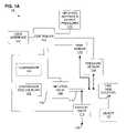
- FIG. 1Ais a block diagram of the hardware components and interconnections of an inflation control system.
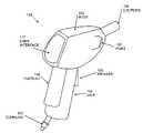
- FIG. 1Bis a perspective view of one embodiment of inflation control system housing.
- FIG. 1Cis a perspective view of exemplary quick disconnect fittings.
- FIG. 2is a block diagram of a digital data processing machine.
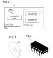
- FIG. 3shows an exemplary signal-bearing medium.
- FIG. 4is a perspective view of exemplary logic circuitry.
- FIG. 5is a flowchart showing a sequence for regulating the inflation of objects.
- FIG. 1Ashows one example, in the form of the inflation control system 100 .
- the inflation control system 100is equally applicable to inflating other inflatable devices such as bicycle tires, and for using other inflating media than air.
- object 122 to be inflatedis not part of the system 100 , the object 122 is show to provide a complete and easily understood illustration.
- the system 100includes a single conduit 118 , as illustrated, or multiple conduits as an alternative.
- the conduit 118is a plenum to receive air from a compressor 124 and provide air to the object 122 to be inflated.
- the conduit 118comprises metal, plastic, or another material similarly capable of holding the desired inflation medium and maintaining its shape.
- the conduit 118is attached to a compressor side coupling 102 and a tire side coupling 104 .
- the tire side coupling 104may be more broadly referred to as an object side coupling in the event the system 100 is implemented to inflate objects other than tires.
- the coupling 104comprises a Shrader valve fitting, Presta valve fitting, or any other fitting suitable to the intended pneumatic tire.
- the coupling 102this coupling is implemented differently depending upon whether the compressor 124 is built-in to the system 100 .
- the compressor 124is not part of the system 100 (but merely shown for the sake of completeness).
- the coupling 102comprises a pneumatic quick-disconnect fitting.
- the coupling 102is a fitting type illustrated by 182 whereas the compressor 124 includes the counterpart fitting 183 .
- the coupling 102may comprise this or a more permanent attachment such as hose clamp, welding, press fit, threaded connector, shrink fit, or other means.
- An inflation valve 106is attached to the conduit 118 , and serves to regulate fluid flow through the conduit 118 according to input from a controller 112 .
- the valve 106is an on/off valve to substantially stop or freely permit fluid flow in the conduit 118 (between couplings 102 , 104 ) according to an electrical, magnetic, or other remotely applied input from the controller 112 .
- the conduit 118is also provided with an exhaust valve 110 , which selectively permits fluid to escape from the conduit 118 under direction of the controller 112 .
- the exhaust valve 110may be placed in the conduit 118 directly, or installed in a side-port 120 as illustrated.
- One example of the exhaust valve 110is a similar component as the valve 106 .
- the system 100also includes temperature 116 and pressure 114 sensors coupled to the conduit 118 appropriately to measure temperature and pressure within the conduit 118 .
- the sensors 116 , 114provide their respective outputs to the controller 112 .
- the temperature sensor 116may comprise a thermo resistor, where increasing temperatures lower the sensor 116 's resistance by an appropriate rate such as 10 k ohm/25 C. degree.
- an appropriate ratesuch as 10 k ohm/25 C. degree.
- there are many other types of temperature sensorsare known, and many of these may be appropriate for use as the sensor 116 .
- the pressure sensor 114comprises a pressure sensor, transducer, transmitter, or other sensing device employing any available technology, such as a piezoelectric member, silicon sensor, capacitive or other diaphragm, Bourdon tube, bellows or any other technology.
- the positioning of the sensor 114recognizes that pressure varies dynamically from the object 122 to the compressor 124 (in most cases increasing), and most accurate pressure measurements will occur nearest the object 112 .
- the pressure sensor 114is positioned sufficiently near the coupling 104 such that pressure measured by the sensor 114 is substantially similar to static pressure of the inflatable object 122 .
- Static pressureis used to refer to pressure strictly within the object 122 as uninfluenced by the compressor 124 , or alternatively, the state of pressure within the object 122 if the coupling 102 were to be closed.
- the distance between the sensor 114 and the coupling 104may be in the range of five centimeters, although this amount may vary depending upon the details of implementation.
- the temperature sensor 116is positioned sufficiently near the coupling 104 such that temperature measured by the sensor 116 is substantially similar to temperature of an inflatable object 122 attached to the object-side coupling 104 .
- this distancemay be in the same range of positioning as the sensor 114 , although this amount may vary depending upon the particular application.
- the temperature sensor 116may be omitted in applications that do not demand such a high level of accuracy as to require temperature compensation.
- the controller 112comprises a digital data processing device coupled to the sensors 116 , 114 and valves 106 , 110 .
- the compressor 112selectively operates the valves 106 , 110 according to information from the sensors 116 , 114 and user interface 117 .
- the controller 112also manages the presentation of human-readable information at the interface 117 .
- the controller 112may be implemented by hardware or software or a combination. The makeup of the controller 112 is described in greater detail below, with reference to an exemplary digital data processing apparatus, logic circuit, and signal bearing medium.
- One specific example of the controller 112is an MCU such as the SONIX model SN8P1909, which is programmed in assembly language.
- the controller 112may be coupled to a record 113 of inflation settings and output pressures.
- the record 113comprises machine-readable digital storage, and contains an array of desired final/output pressures indexed according to various inflation settings such as vehicle make/model/type/year, tire size or location, vehicle inflation profile, season of year, date and/or time, front versus rear tire, etc.
- arrayis used without any intended limitation, as this array may be embodied in an array structure, matrix, lookup table, relational database, linked list, string, computing algorithm, or any other construct that is useful for the purposes illustrated herein.
- the record 113may be reconfigurable by the user, for example, accommodating user specification of target pressures corresponding to various vehicle inflation profiles.
- a user interface 117is coupled to the controller 112 .
- the user interface 117includes a user input facility and a user output facility.
- the input facilitythis may include a keypad, keyboard, dials, buttons, sliding controls, touch screen, or a combination of these or another device for receiving user input.
- a trigger 156FIG. 1B , described below
- This user-activation functionmay be satisfied by one of the previously mentioned input devices, or by another, separate button, wheel, sliding control, detent, tab, etc.
- the output facilitythis may include a visual display (with LCD being one example), sound generating device, mechanical indicator such as digits or dials, or a combination of these or another device for providing a human-readable output.
- the system 100may receive electrical power from 110 VAC, which is reduced and converted to DC by transformer circuitry (not shown).
- the system 100runs on battery power, with one example being a bank of ten 1.2 V, 600 MAH Ni—He rechargeable batteries
- controller 112may be implemented in various forms.
- One exampleis a digital data processing apparatus, as exemplified by the hardware components and interconnections of the digital data processing apparatus 200 of FIG. 2 .
- the apparatus 200includes a processor 202 , such as a microprocessor, personal computer, workstation, controller, microcontroller, state machine, or other processing machine, coupled to storage 204 .
- the storage 204includes a fast-access storage 206 , as well as nonvolatile storage 208 .
- the fast-access storage 206may comprise random access memory (“RAM”), and may be used to store the programming instructions executed by the processor 202 .
- the nonvolatile storage 208may comprise, for example, battery backup RAM, EEPROM, flash PROM, one or more magnetic data storage disks such as a “hard drive”, a tape drive, or any other suitable storage device.
- the apparatus 200also includes an input/output 210 , such as a line, bus, cable, electromagnetic link, or other means for the processor 202 to exchange data with other hardware external to the apparatus 200 .
- the processor 202serves to execute various machine-readable instructions. These instructions may reside in the storage 204 as illustrated in FIG. 2 , another form such as the storage media 300 ( FIG. 3 ), or another form still.
- Some examplesinclude direct access storage (e.g., a conventional “hard drive”, redundant array of inexpensive disks (“RAID”), or another direct access storage device (“DASD”)), serial-access storage such as magnetic or optical tape, electronic non-volatile memory (e.g., ROM, EPROM, flash PROM, or EEPROM), battery backup RAM, optical storage (e.g., CD-ROM, WORM, DVD, digital optical tape), or other suitable signal-bearing media.
- direct access storagee.g., a conventional “hard drive”, redundant array of inexpensive disks (“RAID”), or another direct access storage device (“DASD”)
- serial-access storagesuch as magnetic or optical tape
- electronic non-volatile memorye.g., ROM, EPROM, flash PROM, or EEPROM
- battery backup RAMe
- this disclosureuses logic circuitry instead of computer-executed instructions to implement the controller 124 .
- this circuitrymay be implemented by one or more integrated circuits such as the circuit 400 of FIG. 4 .
- this logicmay be implemented by constructing an application-specific integrated circuit (ASIC) having thousands of tiny integrated transistors.
- ASICapplication-specific integrated circuit
- Such an ASICmay be implemented with CMOS, TTL, VLSI, or another suitable construction.
- Other alternativesinclude a digital signal processing chip (DSP), discrete circuitry (such as resistors, capacitors, diodes, inductors, and transistors), field programmable gate array (FPGA), programmable logic array (PLA), programmable logic device (PLD), and the like.
- DSPdigital signal processing chip
- FPGAfield programmable gate array
- PLAprogrammable logic array
- PLDprogrammable logic device
- the components of the system 100may be provided with a housing such as 150 ( FIG. 1B ).
- the illustrated housing 150encloses the conduit 118 , inflation valve 106 , exhaust valve 110 , pressure sensor 114 , temperature sensor 116 , and controller 112 , which are all hidden from view in FIG. 1B .
- the user interface 117is located at the rear of the body 152 .
- the exhaust port 120may be internal to the housing 150 , or it may extend from the housing 150 as illustrated by 120 as shown in FIG. 1B .
- the shape, layout, and other features of the housing 150may be changed.
- the housing 150assumes a shape that is conducive to handheld manipulation, and application of force suitable to keep the coupling 104 in contact with a tire valve while concurrently viewing the interface 117 .
- the housing's shapeis exemplified by a body 152 attached to a grip 154 that extends at some angle (such as ninety degrees) from the body 152 .
- the housing 150is made of aluminum with a rubber overlay 158 applied to the grip 154 region.
- the body 152includes the tire side coupling 104 at one end, and at the other end of the body, the user interface 117 and the body 152 's attachment to the grip 154 .
- the grip 154Opposite its attachment to the body 152 , the grip 154 includes the compressor side coupling 102 .
- the grip 154may include a trigger 156 for user-control of manual inflation.
- FIG. 5shows a sequence 500 to illustrate one example of the method aspect of this disclosure.
- this sequence 500regulates the inflation of objects.
- the sequence 500is illustrated in the specific context of the system 100 , and in the context of inflating automobile tires with air.
- step 501the user configures the system 100 .
- the userattaches the coupling 102 to a compressor 124 (if there is no compressor integrated into the system), and attaches the system 100 to a power source (if one is not integrated into the system).
- the userattaches the coupling 104 to the tire 122 to be inflated.
- one optionis for the user in step 501 to directly enter a target tire pressure via the interface 117 (“direct entry”).
- the useroperates the interface 117 to enter (step 501 ) one or more desired target inflation pressures for one or more tires, and then starts inflation by activating (step 502 ) the user interface 117 (such as the trigger 156 ).
- the usermay enter a desired inflation pressure of 35 PSI.
- the system 100will then act to fill each tire to the desired inflation pressure of 35 PSI, as discussed in step 502 - 514 , described below.
- the usermay enter several different inflation pressures for differently located or differently sized tires.
- the userenters inflation settings (such as vehicle type) rather than actual pressures, and the controller 112 cross references these inflation settings in the record 113 to determine or compute one or more appropriate target inflation pressures.
- inflation settingssuch as vehicle type
- One example of programmed selectionis where the user selects from several pre-stored vehicle profiles in step 501 , and the controller 112 consults the record 113 to look-up the target pressure corresponding to that profile. And, if the user has not yet defined any profiles, or wishes to change them, in step 501 the controller 112 accepts the user's specification of target pressures for one or more vehicle profiles, and stores them in the record 113 .
- These profilesmay be referred to as inflation profiles, vehicle profiles, user-defined profiles, etc.
- the controller 112allows the user to invoke other pre-programmed inflation pressures by entering other inflation settings such as: (1) make, model, year, or other vehicle identification, (2) summer, winter, spring, fall season, (3) time or date, (4) front versus rear pressures, etc.
- the controller 112cross-references these user-entered inflation settings in the record 113 to lookup or compute one or more pre-programmed target inflation pressures.
- step 501After making the inputs of step 501 , whether manual or automatic, the user squeezes the trigger 156 or other facility of the interface 117 to begin.
- the system 100proceeds to fill each tire until (1) the user releases the trigger 156 in manual mode, or (2) the sensed pressure reaches the target pressure in automatic mode. Details of the inflation cycle are explained below with reference to steps 502 - 514 , below.
- step 502the user interface 117 starts inflation responsive to the user's input, such as a trigger 156 squeeze as discussed above. Accordingly, the controller 112 begins inflation in step 502 .
- the controller 112operates the inflation valve 106 to assume an “on” position, enabling fluid flow between the compressor side 102 and tire side 104 couplings. This permits air to rush in from the compressor 124 into the tire 122 attached to the coupling 104 .
- step 504the controller 112 takes frequent or even continuous pressure readings from the sensor 114 , and asks whether the target pressure (plus a certain margin) has been reached. If not, inflation continues ( 506 ) and step 504 repeats.
- step 504may continually update the user interface 117 to display the pressure being sensed at 114 .
- the controller 112stops inflation (step 508 ) by closing the inflation valve 106 . This is discussed in greater detail below.
- the “target” pressureis established as discussed above (step 501 ) by direct user entry, or by the controller 112 recalling a pre-programmed output pressure from the record 113 as appropriate to the vehicle profile, season, day of the year, vehicle type or make/model/year, or other user-entered inflation settings input (from 501 ).
- the target pressureis not established until the user releases the trigger 156 ; namely, when the user sees that the pressure displayed by the interface 117 (at step 504 ) reaches a desired pressure, the user releases the trigger 156 , thereby establishing the displayed pressure as the target pressure.
- step 504may include the additional operation of temperature-correcting the pressure reading of step 504 .
- Thismay be achieved by the controller 112 reading temperature from the sensor 116 , and using this temperature reading to correct the pressure measured in 504 .
- Correctionmay be achieved, for example, by consulting a lookup table or other appropriate reference in machine-readable storage. More particularly, such a lookup table cross-references different combinations of measured pressure and measure temperature against actual pressure. This table may be prepared by experimentation, or by computation using an equation such as the Ideal gas law, Van der Waals equation, Peng-Robinson equation of state, etc. As a particular example, the lookup table may offset measured pressure according to temperature.
- Step 508ceases inflation, but only after reaching the target pressure plus a prescribed margin ( 504 ).
- the prescribed marginmay be a percentage of the target pressure, a fixed value, a value determined by vehicle type, or another fixed or calculated figure.
- the prescribed marginis 0.5 PSI or another amount where, accounting for the size of conduit 118 , exhaust valve 110 , and tire 122 , the deflate time (described below) will last for a given time such as one second.
- step 508accounts for the inherent error in measuring pressure dynamically (i.e., with valve 106 open), and provides sufficient, intentional, over-inflation so that pressure can be more accurately set by controlled deflation while the valve 106 is closed (as discussed in greater detail below).
- step 508the controller 112 directs the inflation valve 106 to close, thereby preventing fluid flow between the couplings 102 , 104 .
- the sensor 114's reading is more accurate than when the conduit 118 is opened to the compressor 124 .
- steps 510 , 512continuously read pressure measured by the sensor 114 while operating the exhaust valve 120 as needed to reduce measured pressure to the target pressure exactly. These may be conducted continuously or practically continually if sufficient to provide the same effect. Pressure readings ( 510 ) may be compensated for temperature in the same manner as discussed above.
- Steps 510 and 510occur as follows.
- the controller 112 in step 510continuously reads pressure from the sensor 114 , and asks whether the target pressure has been reached. If not, the controller 116 controls the exhaust valve 110 to start (or continue) deflation in step 512 , and step 510 continues.
- step 510may additionally operate the user interface 117 to display the sensed pressure.
- the controller 112stops deflation (step 514 ) by closing the exhaust valve 110 .
- step 510may utilize a slightly elevated target pressure in step 510 , to account for the volume of conduit 118 between the coupling 104 and the inflation valve 106 , since this volume of fluid will escape when the tire 122 is ultimately disconnected from the coupling 104 .
- the conduit 118may be designed such that the volume of conduit between the valve 106 and the coupling 104 is minimal, such that negligible pressure loss occurs when the tire is disconnected from the coupling 104 .
- Step 514ends the sequence 500 .
- the userthen removes the tire 122 from the coupling 104 and proceeds to repeat the sequence for another tire, until finished with all tires.
- any illustrative logical blocks, modules, circuits, and process steps described hereinmay be implemented as electronic hardware, computer software, or combinations of both.
- various illustrative components, blocks, modules, circuits, and stepshave been described above generally in terms of their functionality. Whether such functionality is implemented as hardware or software depends upon the particular application and design constraints imposed on the overall system. Skilled artisans may implement the described functionality in varying ways for each particular application, but such implementation decisions should not be interpreted as causing a departure from the scope of the present invention.
- DSPdigital signal processor
- ASICapplication specific integrated circuit
- FPGAfield programmable gate array
- a general purpose processormay be a microprocessor, but in the alternative, the processor may be any conventional processor, controller, microcontroller, or state machine.
- a processormay also be implemented as a combination of computing devices, e.g., a combination of a DSP and a microprocessor, a plurality of microprocessors, one or more microprocessors in conjunction with a DSP core, or any other such configuration.
- a software modulemay reside in RAM memory, flash memory, ROM memory, EPROM memory, EEPROM memory, registers, hard disk, a removable disk, a CD-ROM, DVD, or any other form of storage medium known in the art.
- An exemplary storage mediumis coupled to the processor such the processor can read information from, and write information to, the storage medium.
- the storage mediummay be integral to the processor.
- the processor and the storage mediummay reside in an ASIC.
Landscapes
- Engineering & Computer Science (AREA)
- Mechanical Engineering (AREA)
- Measuring Fluid Pressure (AREA)
- Vehicle Cleaning, Maintenance, Repair, Refitting, And Outriggers (AREA)
- Control Of Fluid Pressure (AREA)
Abstract
Description
Claims (19)
Priority Applications (3)
| Application Number | Priority Date | Filing Date | Title |
|---|---|---|---|
| US11/353,655US7331221B2 (en) | 2006-02-13 | 2006-02-13 | Precision inflation control device |
| EP06017295AEP1818228A3 (en) | 2006-02-13 | 2006-08-18 | Precision inflation control device and method for regulating inflation of an object |
| AU2006203641AAU2006203641B2 (en) | 2006-02-13 | 2006-08-23 | Precision inflation control device |
Applications Claiming Priority (1)
| Application Number | Priority Date | Filing Date | Title |
|---|---|---|---|
| US11/353,655US7331221B2 (en) | 2006-02-13 | 2006-02-13 | Precision inflation control device |
Publications (2)
| Publication Number | Publication Date |
|---|---|
| US20070186636A1 US20070186636A1 (en) | 2007-08-16 |
| US7331221B2true US7331221B2 (en) | 2008-02-19 |
Family
ID=37955262
Family Applications (1)
| Application Number | Title | Priority Date | Filing Date |
|---|---|---|---|
| US11/353,655Expired - Fee RelatedUS7331221B2 (en) | 2006-02-13 | 2006-02-13 | Precision inflation control device |
Country Status (3)
| Country | Link |
|---|---|
| US (1) | US7331221B2 (en) |
| EP (1) | EP1818228A3 (en) |
| AU (1) | AU2006203641B2 (en) |
Cited By (18)
| Publication number | Priority date | Publication date | Assignee | Title |
|---|---|---|---|---|
| US20100172737A1 (en)* | 2004-09-22 | 2010-07-08 | Avery Dennison Corporation | High-speed rfid circuit placement method and device |
| EP2407354A1 (en) | 2010-07-12 | 2012-01-18 | Susan Eve Vecht-Lifshitz | Incentive-based method and system for reducing vehicle fuel consumption |
| US20120067119A1 (en)* | 2009-05-26 | 2012-03-22 | Diba Industries, Inc. | Pressure-sensor based liquid-level measuring device with reduced capillary effect |
| USD667713S1 (en)* | 2012-03-08 | 2012-09-25 | Mathew Inskeep | Extendable automatic tire wrench |
| US20160214441A1 (en)* | 2013-08-29 | 2016-07-28 | Agco International Gmbh | Tyre inflation control arrangement |
| US20160368332A1 (en)* | 2015-06-16 | 2016-12-22 | Citic Dicastal Co., Ltd | Device and Method for Measuring Air Tightness of Aluminum Alloy Hub or Tyre |
| USD834070S1 (en) | 2017-12-12 | 2018-11-20 | Milwaukee Electric Tool Corporation | Inflator |
| WO2019014640A1 (en) | 2017-07-14 | 2019-01-17 | Equalaire Systems, Inc. | Electronic control module for a tire inflation system |
| US10220657B2 (en)* | 2016-02-29 | 2019-03-05 | AGCO Incorporated GmbH | Tire inflation control arrangement |
| US10563783B2 (en) | 2018-07-12 | 2020-02-18 | Innoflate, LLC | Pressure regulating device |
| US10974701B2 (en) | 2018-02-28 | 2021-04-13 | Milwaukee Electric Tool Corporation | Inflator with dynamic pressure compensation |
| US11002264B2 (en)* | 2018-07-05 | 2021-05-11 | Makita Corporation | Portable inflator |
| US11383076B2 (en) | 2020-10-01 | 2022-07-12 | Lifebridge Technologies, Llc | Pump regulation based on heart size and function |
| US11872852B2 (en) | 2019-02-07 | 2024-01-16 | Pressure Systems International, Llc | Enhanced tire inflation system |
| US11896812B1 (en) | 2023-01-27 | 2024-02-13 | Lifebridge Technologies Llc | Versatile modular heart pump for non-blood contacting ventricular function augmentation |
| US12115363B1 (en) | 2023-08-10 | 2024-10-15 | Lifebridge Technologies Llc | System and method for introducing a construct either on or around the surface of the heart |
| US12263332B2 (en) | 2022-09-13 | 2025-04-01 | Lifebridge Technologies Llc | Material characteristics ideal for providing either partial or total mechanical support to the failing or arrested heart and method for developing ideal characteristics for underlying cardiac disorders |
| US12440338B2 (en) | 2023-12-05 | 2025-10-14 | Lifebridge Technologies Llc | Minimally invasive heart pump with modular adjustable construct insertion |
Families Citing this family (10)
| Publication number | Priority date | Publication date | Assignee | Title |
|---|---|---|---|---|
| US20080110250A1 (en)* | 2006-10-20 | 2008-05-15 | Jones Russell F | Tire pressure monitoring device, system and method |
| US8015864B2 (en)* | 2009-06-04 | 2011-09-13 | Measurement Ltd. | Digital tire pressure gauge with bleed valve |
| GB2509666B (en)* | 2011-10-31 | 2017-12-13 | Measurement Ltd | Combination tire temperature, pressure and depth measuring device |
| US10086803B2 (en)* | 2013-08-27 | 2018-10-02 | Ford Global Technologies, Llc | Pump with tire fill assist |
| JP6315477B2 (en)* | 2014-11-28 | 2018-04-25 | 株式会社神戸製鋼所 | Tire testing equipment |
| CN105000000A (en)* | 2015-07-10 | 2015-10-28 | 上海爱辇贸易有限公司 | Automobile tire inflation device |
| US10657757B2 (en)* | 2015-07-31 | 2020-05-19 | Daniel J. Burrows | Hybrid air machine |
| GB2557289A (en)* | 2016-12-05 | 2018-06-20 | Lematec Co Ltd | Apparatus for inspecting tires |
| AU2019340606B2 (en) | 2018-09-12 | 2022-03-17 | Signode India Limited | Inflator with automatic shut-off functionality |
| CN114281120B (en)* | 2021-12-27 | 2024-03-26 | 北京北方华创微电子装备有限公司 | Semiconductor process equipment and chamber pressure control method |
Citations (32)
| Publication number | Priority date | Publication date | Assignee | Title |
|---|---|---|---|---|
| US4333491A (en) | 1979-05-18 | 1982-06-08 | Knubley John S | Air dispensing apparatus |
| US4574267A (en) | 1982-05-06 | 1986-03-04 | Trw Inc. | Tire pressure warning system |
| US4776766A (en) | 1987-08-14 | 1988-10-11 | Interdynamics, Inc. | Portable air pump assembly and detechable safety lamp for automotive vehicle |
| US5505080A (en) | 1994-05-12 | 1996-04-09 | Tellair Corporation | Tire pressure management system |
| US5587698A (en) | 1992-02-05 | 1996-12-24 | Genna; Robert A. | Automatic tire pressure control system for a vehicle |
| US5606123A (en) | 1995-05-16 | 1997-02-25 | Rabizadeh; Masoud | Tire pressure monitoring device capable of being folded |
| WO2002007993A2 (en) | 2000-07-26 | 2002-01-31 | Bridgestone/Firestone, Inc. | Electronic tire management system |
| US20020075145A1 (en) | 2000-07-26 | 2002-06-20 | Hardman Gordon E. | Electronic tire management system |
| US20020101067A1 (en) | 1995-06-07 | 2002-08-01 | Breed David S. | Inflator system |
| US6441732B1 (en) | 2001-05-02 | 2002-08-27 | Nokian Tyres Plc | System for displaying tire characteristics |
| EP1245413A2 (en) | 2001-03-29 | 2002-10-02 | The Goodyear Tire & Rubber Company | A method of monitoring a tire condition using a drive over reader |
| EP1291230A2 (en) | 2001-09-10 | 2003-03-12 | The Goodyear Tire & Rubber Company | A tire pressure initiated vehicle control system |
| US6561017B1 (en) | 2001-12-04 | 2003-05-13 | Dana Corporation | Tire inflation method |
| WO2003047887A1 (en) | 2001-12-04 | 2003-06-12 | Dana Corporation | Tire pressure monitoring method |
| WO2003047888A1 (en) | 2001-12-04 | 2003-06-12 | Dana Corporation | Target tire pressure learning method |
| EP1347619A2 (en) | 2002-03-22 | 2003-09-24 | Sun Microsystems, Inc. | Method and system for storing user preferences |
| US6666518B2 (en)* | 2000-10-03 | 2003-12-23 | Drake Corp. | Chair adapted to be stacked |
| US20040007302A1 (en)* | 2002-07-11 | 2004-01-15 | Hamilton Brian K. | Tire pressure maintenance and monitoring system |
| US20040021560A1 (en) | 2002-07-31 | 2004-02-05 | Kaoru Sasaki | Tire condition detecting system for wheeled vehicle |
| US20040021561A1 (en) | 2002-07-31 | 2004-02-05 | Kaoru Sasaki | Tire condition indicating system for wheeled vehicle |
| US20040099055A1 (en) | 2002-11-20 | 2004-05-27 | Honda Motor Co., Ltd. | Tire pressure monitoring system |
| WO2004085172A2 (en) | 2003-03-21 | 2004-10-07 | Ingram Rupert Ii | Tire management system and method |
| US6826951B1 (en)* | 1998-01-15 | 2004-12-07 | International Marketing, Inc. | Tire management system and method for surveying and servicing a vehicle tire |
| US6838983B1 (en)* | 2003-08-27 | 2005-01-04 | Alex Yung Kan Wong | Precision inflation device |
| US20050097949A1 (en) | 2003-11-11 | 2005-05-12 | Siemens Aktiengesellschaft | System for monitoring a vehicle with pneumatic tires, signal analysis method, and vehicle tire |
| US6894607B1 (en) | 2001-12-03 | 2005-05-17 | Dana Corporation | Tire pressure management system valve integrity verification method |
| US20050199328A1 (en) | 2004-03-12 | 2005-09-15 | Bruce Schoenberger | Pressure sensing method and apparatus |
| EP1043179B1 (en) | 1999-04-09 | 2005-10-26 | Delphi Technologies, Inc. | System for monitoring tire pressure of a vehicle |
| US7032611B1 (en)* | 1999-09-02 | 2006-04-25 | Xiayang Sheng | Pressure regulator and method of use |
| US7051585B2 (en)* | 2001-12-04 | 2006-05-30 | Dana Corporation | Supply and tire pressure sensing apparatus and method |
| US20060180256A1 (en)* | 2005-02-14 | 2006-08-17 | Mittal Chander P | Tire pressurization system |
| US7171848B2 (en)* | 2002-04-11 | 2007-02-06 | Continental Tire North America, Inc. | Tire status detection system and method |
Family Cites Families (3)
| Publication number | Priority date | Publication date | Assignee | Title |
|---|---|---|---|---|
| FR2584347B1 (en)* | 1985-07-04 | 1988-05-27 | Houbre Maurice | METHOD FOR AUTOMATIC INFLATION OF TIRES AND DEVICE FOR IMPLEMENTING SAME |
| GB2323453A (en)* | 1997-03-21 | 1998-09-23 | Andre Alan Donald King | Apparatus for inflating vehicle tyre incorporating set pressure reading device |
| DE29715197U1 (en)* | 1997-08-23 | 1997-11-06 | Armaturenfabrik Ernst Horn GmbH, 24937 Flensburg | Device for checking and adjusting the tire pressure of motor vehicles |
- 2006
- 2006-02-13USUS11/353,655patent/US7331221B2/ennot_activeExpired - Fee Related
- 2006-08-18EPEP06017295Apatent/EP1818228A3/ennot_activeWithdrawn
- 2006-08-23AUAU2006203641Apatent/AU2006203641B2/ennot_activeCeased
Patent Citations (41)
| Publication number | Priority date | Publication date | Assignee | Title |
|---|---|---|---|---|
| US4333491A (en) | 1979-05-18 | 1982-06-08 | Knubley John S | Air dispensing apparatus |
| US4574267A (en) | 1982-05-06 | 1986-03-04 | Trw Inc. | Tire pressure warning system |
| US4776766A (en) | 1987-08-14 | 1988-10-11 | Interdynamics, Inc. | Portable air pump assembly and detechable safety lamp for automotive vehicle |
| EP0303469A2 (en) | 1987-08-14 | 1989-02-15 | Interdynamics, Inc. | Portable air pump assembly |
| US5587698A (en) | 1992-02-05 | 1996-12-24 | Genna; Robert A. | Automatic tire pressure control system for a vehicle |
| US5505080A (en) | 1994-05-12 | 1996-04-09 | Tellair Corporation | Tire pressure management system |
| US5606123A (en) | 1995-05-16 | 1997-02-25 | Rabizadeh; Masoud | Tire pressure monitoring device capable of being folded |
| US20020101067A1 (en) | 1995-06-07 | 2002-08-01 | Breed David S. | Inflator system |
| US6905135B2 (en) | 1995-06-07 | 2005-06-14 | Automotive Technologies International, Inc. | Inflator system |
| US6826951B1 (en)* | 1998-01-15 | 2004-12-07 | International Marketing, Inc. | Tire management system and method for surveying and servicing a vehicle tire |
| EP1043179B1 (en) | 1999-04-09 | 2005-10-26 | Delphi Technologies, Inc. | System for monitoring tire pressure of a vehicle |
| US7032611B1 (en)* | 1999-09-02 | 2006-04-25 | Xiayang Sheng | Pressure regulator and method of use |
| US20020075145A1 (en) | 2000-07-26 | 2002-06-20 | Hardman Gordon E. | Electronic tire management system |
| WO2002007993A2 (en) | 2000-07-26 | 2002-01-31 | Bridgestone/Firestone, Inc. | Electronic tire management system |
| US6666518B2 (en)* | 2000-10-03 | 2003-12-23 | Drake Corp. | Chair adapted to be stacked |
| EP1245413A2 (en) | 2001-03-29 | 2002-10-02 | The Goodyear Tire & Rubber Company | A method of monitoring a tire condition using a drive over reader |
| US6441732B1 (en) | 2001-05-02 | 2002-08-27 | Nokian Tyres Plc | System for displaying tire characteristics |
| EP1291230A2 (en) | 2001-09-10 | 2003-03-12 | The Goodyear Tire & Rubber Company | A tire pressure initiated vehicle control system |
| US6894607B1 (en) | 2001-12-03 | 2005-05-17 | Dana Corporation | Tire pressure management system valve integrity verification method |
| WO2003047887A1 (en) | 2001-12-04 | 2003-06-12 | Dana Corporation | Tire pressure monitoring method |
| US6666078B1 (en) | 2001-12-04 | 2003-12-23 | Dana Corporation | Target tire pressure learning method |
| US7051585B2 (en)* | 2001-12-04 | 2006-05-30 | Dana Corporation | Supply and tire pressure sensing apparatus and method |
| WO2003047889A1 (en) | 2001-12-04 | 2003-06-12 | Dana Corporation | Tire inflation method with continious and pulsed air flow |
| WO2003047888A1 (en) | 2001-12-04 | 2003-06-12 | Dana Corporation | Target tire pressure learning method |
| US6868719B1 (en)* | 2001-12-04 | 2005-03-22 | Dana Corporation | Tire pressure monitoring method |
| US6561017B1 (en) | 2001-12-04 | 2003-05-13 | Dana Corporation | Tire inflation method |
| US6865930B1 (en)* | 2001-12-04 | 2005-03-15 | Dana Corporation | Tire inflation method |
| EP1347619A2 (en) | 2002-03-22 | 2003-09-24 | Sun Microsystems, Inc. | Method and system for storing user preferences |
| US7171848B2 (en)* | 2002-04-11 | 2007-02-06 | Continental Tire North America, Inc. | Tire status detection system and method |
| US20040007302A1 (en)* | 2002-07-11 | 2004-01-15 | Hamilton Brian K. | Tire pressure maintenance and monitoring system |
| US6744356B2 (en) | 2002-07-11 | 2004-06-01 | Autoliv Asp, Inc. | Tire pressure maintenance and monitoring system |
| US6888450B2 (en) | 2002-07-31 | 2005-05-03 | Yamaha Hatsudoki Kabushiki Kaisha | Tire condition indicating system for wheeled vehicle |
| US20040021561A1 (en) | 2002-07-31 | 2004-02-05 | Kaoru Sasaki | Tire condition indicating system for wheeled vehicle |
| US20040021560A1 (en) | 2002-07-31 | 2004-02-05 | Kaoru Sasaki | Tire condition detecting system for wheeled vehicle |
| US20040099055A1 (en) | 2002-11-20 | 2004-05-27 | Honda Motor Co., Ltd. | Tire pressure monitoring system |
| US20050102073A1 (en) | 2003-03-21 | 2005-05-12 | Ingram Rupert H.Ii | Tire management system and method |
| WO2004085172A2 (en) | 2003-03-21 | 2004-10-07 | Ingram Rupert Ii | Tire management system and method |
| US6838983B1 (en)* | 2003-08-27 | 2005-01-04 | Alex Yung Kan Wong | Precision inflation device |
| US20050097949A1 (en) | 2003-11-11 | 2005-05-12 | Siemens Aktiengesellschaft | System for monitoring a vehicle with pneumatic tires, signal analysis method, and vehicle tire |
| US20050199328A1 (en) | 2004-03-12 | 2005-09-15 | Bruce Schoenberger | Pressure sensing method and apparatus |
| US20060180256A1 (en)* | 2005-02-14 | 2006-08-17 | Mittal Chander P | Tire pressurization system |
Non-Patent Citations (15)
| Title |
|---|
| 2-10 Wheel Tire Pressue Monitors. Doran Mfg Llc. http://www.doranmfg.com/doran<SUB>-</SUB>pressure<SUB>-</SUB>pro.htm. Nov. 3, 2005. |
| 2-10 Wheel Tire Pressue Monitors. Doran Mfg Llc. http://www.doranmfg.com/doran—pressure—pro.htm. Nov. 3, 2005. |
| Accutire Set Point Programmable Tire Gauge. http://www.autogeek.net/tire-gauge.html. before Jan. 24, 2006. |
| Air Compressor and Digital Tire Pressure Gauge. The Home Store. http://homestore3.com/noname22.html; http://store.yahoo.com/store3-store/noname22.html. Nov. 3, 2005. |
| An Evaluation of Existing Tire Pressure Monitoring systems. U.S. Dept. of Transportation. National Highway Traffic Safety Administration. Jul. 2001. |
| Cordless Inflator with Light. http://www.safety-devices.com/cc2400.htm. before Jan. 24, 2006. |
| Equipment News. http://bultransporter.com/mag/transportation<SUB>-</SUB>equipment<SUB>-</SUB>news/. before Jan. 24, 2006. |
| Equipment News. http://bultransporter.com/mag/transportation—equipment—news/. before Jan. 24, 2006. |
| Intercomp Memory Tire Gauge. Users Manual. www.intercompco-racing.com. Oct. 2003. |
| Longacre Tire Inflater. http://www.cdoc.com/detail.asp?id+14877&str+4000-2525-0253&name . . . before Jan. 24, 2006. |
| Programmable Tire Gauge, et al. AutoSport. http://www.autosportcatalog.com/index.cfm?fa+s&keywords+tire%2520gauge&sc+7542. |
| Smart Air. http://www.smartair.com/CLTdatasheet.htm. Jan. 28, 2006. |
| Smartpressure Tire Gauge. Brookstone. Oct. 30, 2003. |
| Weakman, K. Intelligent Tire Inflator. http://www.circuitcellar.com/msp430/hc.htm. Dec. 17, 2001. |
| Williams, P. CanadianDriver:Product Review-Michelin Tire Pressure Gauge and Air Pumps. http://canadiandriver.com/articles/pw/michelin.htm. Jul. 13, 2004. |
Cited By (26)
| Publication number | Priority date | Publication date | Assignee | Title |
|---|---|---|---|---|
| US20100172737A1 (en)* | 2004-09-22 | 2010-07-08 | Avery Dennison Corporation | High-speed rfid circuit placement method and device |
| US20120067119A1 (en)* | 2009-05-26 | 2012-03-22 | Diba Industries, Inc. | Pressure-sensor based liquid-level measuring device with reduced capillary effect |
| EP2407354A1 (en) | 2010-07-12 | 2012-01-18 | Susan Eve Vecht-Lifshitz | Incentive-based method and system for reducing vehicle fuel consumption |
| USD667713S1 (en)* | 2012-03-08 | 2012-09-25 | Mathew Inskeep | Extendable automatic tire wrench |
| US20160214441A1 (en)* | 2013-08-29 | 2016-07-28 | Agco International Gmbh | Tyre inflation control arrangement |
| US9701164B2 (en)* | 2013-08-29 | 2017-07-11 | Agco International Gmbh | Tyre inflation control arrangement |
| US20160368332A1 (en)* | 2015-06-16 | 2016-12-22 | Citic Dicastal Co., Ltd | Device and Method for Measuring Air Tightness of Aluminum Alloy Hub or Tyre |
| US10234352B2 (en)* | 2015-06-16 | 2019-03-19 | Citic Dicastal Co., Ltd | Device and method for measuring air tightness of aluminum alloy hub or tyre |
| US10220657B2 (en)* | 2016-02-29 | 2019-03-05 | AGCO Incorporated GmbH | Tire inflation control arrangement |
| EP3651999A4 (en)* | 2017-07-14 | 2021-01-20 | Equalaire Systems, Inc. | Electronic control module for a tire inflation system |
| US11505013B2 (en) | 2017-07-14 | 2022-11-22 | Pressure Systems International, Llc | Electronic control module for a tire inflation system |
| US12194787B2 (en) | 2017-07-14 | 2025-01-14 | Pressure Systems International, Llc | Electronic control module for a tire inflation system |
| WO2019014640A1 (en) | 2017-07-14 | 2019-01-17 | Equalaire Systems, Inc. | Electronic control module for a tire inflation system |
| EP4159489A1 (en)* | 2017-07-14 | 2023-04-05 | Pressure Systems International, LLC | Electronic control module for a tire inflation system |
| USD834070S1 (en) | 2017-12-12 | 2018-11-20 | Milwaukee Electric Tool Corporation | Inflator |
| US11679744B2 (en) | 2018-02-28 | 2023-06-20 | Milwaukee Electric Tool Corporation | Inflator with dynamic pressure compensation |
| US10974701B2 (en) | 2018-02-28 | 2021-04-13 | Milwaukee Electric Tool Corporation | Inflator with dynamic pressure compensation |
| US11002264B2 (en)* | 2018-07-05 | 2021-05-11 | Makita Corporation | Portable inflator |
| US10563783B2 (en) | 2018-07-12 | 2020-02-18 | Innoflate, LLC | Pressure regulating device |
| US11872852B2 (en) | 2019-02-07 | 2024-01-16 | Pressure Systems International, Llc | Enhanced tire inflation system |
| US11383076B2 (en) | 2020-10-01 | 2022-07-12 | Lifebridge Technologies, Llc | Pump regulation based on heart size and function |
| US12263332B2 (en) | 2022-09-13 | 2025-04-01 | Lifebridge Technologies Llc | Material characteristics ideal for providing either partial or total mechanical support to the failing or arrested heart and method for developing ideal characteristics for underlying cardiac disorders |
| US11896812B1 (en) | 2023-01-27 | 2024-02-13 | Lifebridge Technologies Llc | Versatile modular heart pump for non-blood contacting ventricular function augmentation |
| US12115363B1 (en) | 2023-08-10 | 2024-10-15 | Lifebridge Technologies Llc | System and method for introducing a construct either on or around the surface of the heart |
| US12377259B2 (en) | 2023-08-10 | 2025-08-05 | Lifebridge Technologies Llc | System and method for introducing a construct either on or around the surface of the heart |
| US12440338B2 (en) | 2023-12-05 | 2025-10-14 | Lifebridge Technologies Llc | Minimally invasive heart pump with modular adjustable construct insertion |
Also Published As
| Publication number | Publication date |
|---|---|
| AU2006203641B2 (en) | 2008-07-03 |
| EP1818228A3 (en) | 2010-11-03 |
| EP1818228A2 (en) | 2007-08-15 |
| US20070186636A1 (en) | 2007-08-16 |
| AU2006203641A1 (en) | 2007-08-30 |
Similar Documents
| Publication | Publication Date | Title |
|---|---|---|
| US7331221B2 (en) | Precision inflation control device | |
| US5891277A (en) | Automotive tire inflation system | |
| US5611875A (en) | Automotive tire inflation system | |
| US10813470B2 (en) | System and method for improved pressure adjustment | |
| US6838983B1 (en) | Precision inflation device | |
| US7458270B2 (en) | Inflation and pressure gauge apparatus | |
| CA2043682C (en) | Integrated process control valve | |
| WO2007113732A2 (en) | Inflation system | |
| US6826951B1 (en) | Tire management system and method for surveying and servicing a vehicle tire | |
| CA2354288C (en) | Refrigerant gauge manifold with built-in charging calculator | |
| US9694630B2 (en) | Method of determining tire pressure | |
| US20060010898A1 (en) | System for refrigerant charging with constant volume tank | |
| US7040153B2 (en) | Tire inflation gauge technology | |
| WO2013181181A1 (en) | Refrigerant recovery unit with diagnostic interface | |
| US12296625B2 (en) | System for managing tire pressures of a vehicle | |
| TW202100070A (en) | Air mattress control system | |
| US10583762B2 (en) | Control system for a pneumatic support mechanism | |
| CN102556008A (en) | Simple automobile tire automatic inflation device and inflation method | |
| CN110261091A (en) | A kind of variable pump dry testing method and device | |
| JP6290404B2 (en) | Device for sealing and air-filling inflatable objects | |
| WO1999036850A1 (en) | Tire management system and method for surveying and servicing a vehicle tire | |
| WO2006095144A1 (en) | Electronic vehicle tyre inflator | |
| TWI659172B (en) | Fast and accurate measurement of tire pressure air gun structure | |
| JP2017501047A5 (en) | ||
| CN220410521U (en) | Tire inflation device with temperature detection function |
Legal Events
| Date | Code | Title | Description |
|---|---|---|---|
| AS | Assignment | Owner name:WISE, ROBERT W., CALIFORNIA Free format text:ASSIGNMENT OF ASSIGNORS INTEREST;ASSIGNOR:GAO, SHAWN;REEL/FRAME:017362/0079 Effective date:20060201 | |
| AS | Assignment | Owner name:GLENN PATENT GROUP, CALIFORNIA Free format text:LIEN;ASSIGNOR:WERKART;REEL/FRAME:025766/0117 Effective date:20110110 | |
| REMI | Maintenance fee reminder mailed | ||
| LAPS | Lapse for failure to pay maintenance fees | ||
| REIN | Reinstatement after maintenance fee payment confirmed | ||
| FP | Lapsed due to failure to pay maintenance fee | Effective date:20120219 | |
| FEPP | Fee payment procedure | Free format text:PETITION RELATED TO MAINTENANCE FEES FILED (ORIGINAL EVENT CODE: PMFP); ENTITY STATUS OF PATENT OWNER: SMALL ENTITY | |
| FPAY | Fee payment | Year of fee payment:4 | |
| SULP | Surcharge for late payment | ||
| FEPP | Fee payment procedure | Free format text:PETITION RELATED TO MAINTENANCE FEES GRANTED (ORIGINAL EVENT CODE: PMFG); ENTITY STATUS OF PATENT OWNER: SMALL ENTITY | |
| PRDP | Patent reinstated due to the acceptance of a late maintenance fee | Effective date:20160607 | |
| STCF | Information on status: patent grant | Free format text:PATENTED CASE | |
| LAPS | Lapse for failure to pay maintenance fees | Free format text:PATENT EXPIRED FOR FAILURE TO PAY MAINTENANCE FEES (ORIGINAL EVENT CODE: EXP.); ENTITY STATUS OF PATENT OWNER: SMALL ENTITY | |
| STCH | Information on status: patent discontinuation | Free format text:PATENT EXPIRED DUE TO NONPAYMENT OF MAINTENANCE FEES UNDER 37 CFR 1.362 | |
| FP | Lapsed due to failure to pay maintenance fee | Effective date:20200219 |