US7329815B2 - Cable with offset filler - Google Patents
Cable with offset fillerDownload PDFInfo
- Publication number
- US7329815B2 US7329815B2US11/185,572US18557205AUS7329815B2US 7329815 B2US7329815 B2US 7329815B2US 18557205 AUS18557205 AUS 18557205AUS 7329815 B2US7329815 B2US 7329815B2
- Authority
- US
- United States
- Prior art keywords
- cable
- filler
- twisted pairs
- cables
- length
- Prior art date
- Legal status (The legal status is an assumption and is not a legal conclusion. Google has not performed a legal analysis and makes no representation as to the accuracy of the status listed.)
- Expired - Lifetime
Links
Images


Classifications
- H—ELECTRICITY
- H01—ELECTRIC ELEMENTS
- H01B—CABLES; CONDUCTORS; INSULATORS; SELECTION OF MATERIALS FOR THEIR CONDUCTIVE, INSULATING OR DIELECTRIC PROPERTIES
- H01B11/00—Communication cables or conductors
- H01B11/02—Cables with twisted pairs or quads
- H01B11/06—Cables with twisted pairs or quads with means for reducing effects of electromagnetic or electrostatic disturbances, e.g. screens
- H01B11/08—Screens specially adapted for reducing cross-talk
- H—ELECTRICITY
- H01—ELECTRIC ELEMENTS
- H01B—CABLES; CONDUCTORS; INSULATORS; SELECTION OF MATERIALS FOR THEIR CONDUCTIVE, INSULATING OR DIELECTRIC PROPERTIES
- H01B11/00—Communication cables or conductors
- H01B11/02—Cables with twisted pairs or quads
- H01B11/04—Cables with twisted pairs or quads with pairs or quads mutually positioned to reduce cross-talk
- H—ELECTRICITY
- H01—ELECTRIC ELEMENTS
- H01B—CABLES; CONDUCTORS; INSULATORS; SELECTION OF MATERIALS FOR THEIR CONDUCTIVE, INSULATING OR DIELECTRIC PROPERTIES
- H01B11/00—Communication cables or conductors
- H01B11/02—Cables with twisted pairs or quads
- H01B11/06—Cables with twisted pairs or quads with means for reducing effects of electromagnetic or electrostatic disturbances, e.g. screens
- Y—GENERAL TAGGING OF NEW TECHNOLOGICAL DEVELOPMENTS; GENERAL TAGGING OF CROSS-SECTIONAL TECHNOLOGIES SPANNING OVER SEVERAL SECTIONS OF THE IPC; TECHNICAL SUBJECTS COVERED BY FORMER USPC CROSS-REFERENCE ART COLLECTIONS [XRACs] AND DIGESTS
- Y10—TECHNICAL SUBJECTS COVERED BY FORMER USPC
- Y10T—TECHNICAL SUBJECTS COVERED BY FORMER US CLASSIFICATION
- Y10T29/00—Metal working
- Y10T29/49—Method of mechanical manufacture
- Y10T29/49002—Electrical device making
- Y10T29/49117—Conductor or circuit manufacturing
Definitions
- the present inventionrelates to cables made of twisted conductor pairs. More specifically, the present invention relates to twisted pair cables for high-speed data communications applications.
- a typical twisted pairincludes two insulated conductors twisted together along a longitudinal axis.
- the twisted pair cablesmust meet specific standards of performance in order to efficiently and accurately transmit the data between the communication devices. If cables do not at least satisfy these standards, the integrity of their signals is jeopardized. Industry standards govern the physical dimensions, the performance, and the safety of the cables. For example, in the United States, the Electronic Industries Association/Telecommunications Industry Association (EIA/TIA) provides standards regarding the performance specifications of data cables. Several foreign countries have also adopted these or similar standards.
- EIA/TIAElectronic Industries Association/Telecommunications Industry Association
- the performance of twisted pair cablesis evaluated using several parameters, including dimensional properties, interoperability, impedance, attenuation, and crosstalk.
- the standardsrequire that the cables perform within certain parameter boundaries. For instance, a maximum, average outer cable diameter of 0.250′′ is specified for many twisted pair cable types.
- the standardsalso require that the cables perform within certain electrical boundaries.
- the range of the parameter boundariesvaries depending on the attributes of the signal to be propagated over the cable. In general, as the speed of a data signal increases, the signal becomes more sensitive to undesirable influences from the cable, such as the effects of impedance, attenuation, and crosstalk. Therefore, high-speed signals require better cable performance in order to maintain adequate signal integrity.
- impedanceis a unit of measure, expressed in Ohms, of the total opposition offered to the flow of an electrical signal. Resistance, capacitance, and inductance each contribute to the impedance of a cable's twisted pairs. Theoretically, the impedance of the twisted pair is directly proportional to the inductance from conductor effects and inversely proportional to the capacitance from insulator effects.
- Impedanceis also defined as the best “path” for data to traverse. For instance, if a signal is being transmitted at an impedance of 100 Ohms, it is important that the cabling over which it propagates also possess an impedance of 100 Ohms. Any deviation from this impedance match at any point along the cable will result in reflection of part of the transmitted signal back towards the transmission end of the cable, thereby degrading the transmitted signal. This degradation due to signal reflection is known as return loss.
- the impedance of the twisted pairis influenced by the physical and electrical attributes of the twisted pair, including: the dielectric properties of the materials proximate to each conductor; the diameter of the conductor; the diameter of the insulation material around the conductor; the distance between the conductors; the relationships between the twisted pairs; the twisted pair lay lengths (distance to complete one twist cycle); the overall cable lay length; and the tightness of the jacket surrounding the twisted pairs.
- the impedance of the twisted pairmay deviate over the length of the pair.
- a deviation in impedanceoccurs at any point where there is a change in the physical attributes of the twisted pair. For example, an impedance deviation will result from a simple increase in the distance between the conductors of the twisted pair.
- the impedancewill increase because impedance is known to be directly proportional to the distance between the conductors of the twisted pair.
- the allowable impedance variation over the length of a cableis typically standardized.
- the EIA/TIA standards for cable performancerequire that the impedance of a cable vary only within a limited range of values. Typically, these ranges have allowed for substantial variations in impedance because the integrity of traditional data signals has been maintained over these ranges.
- the same ranges of impedance variationsjeopardize the integrity of high-speed signals because the undesirable effects of the impedance variations are accentuated when higher speed signals are transmitted. Therefore, accurate and efficient transmissions of high-speed signals, such as signals with aggregate speeds approaching and surpassing 10 gigabits per second, benefit from stricter control of the impedance variations over the length of a cable.
- post-manufacture manipulations of a cablesuch as twisting the cable, should not introduce significant impedance mismatches into the cable.
- Attenuationrepresents signal loss as an electrical signal propagates along a conductor length. A signal, if attenuated too much, becomes unrecognizable to a receiving device. To make sure this doesn't happen, standards committees have established limits on the amount of loss that is acceptable.
- the attenuation of a signaldepends on several factors, including: the dielectric constants of the materials surrounding the conductor; the impedance of the conductor; the frequency of the signal; the length of the conductor; and the diameter of the conductor.
- the adopted standardsregulate some of these factors. For example, the EIA/TIA standards govern the allowable sizes of conductors for the twisted pairs.
- the materials surrounding the conductorsaffect signal attenuation because materials with better dielectric properties (e.g., lower dielectric constants) tend to minimize signal loss. Accordingly, many conventional cables use materials such as polyethylene and fluorinated ethylene propylene (FEP) to insulate the conductors. These materials usually provide lower dielectric loss than other materials with higher dielectric constants, such as polyvinyl chloride (PVC). Further, some conventional cables have sought to reduce signal loss by maximizing the amount of air surrounding the twisted pairs. Because of its low dielectric constant (1.0), air is a good insulator against signal attenuation.
- FEPfluorinated ethylene propylene
- the material of the jacketalso affects attenuation, especially when a cable does not contain internal shielding.
- Typical jacket materials used with conventional cablestend to have higher dielectric constants, which can contribute to greater signal loss. Consequently, many conventional cables use a “loose-tube” construction that helps distance the jacket from unshielded twisted pairs.
- Crosstalkrepresents signal degradation due to capacitive and inductive coupling between the twisted pairs.
- Each active twisted pairnaturally produces electromagnetic fields (collectively “the fields” or “the interference fields”) about its conductors. These fields are also known as electrical noise or interference because the fields can undesirably affect the signals being transmitted along other proximate conductors.
- the fieldstypically emanate outwardly from the source conductor over a finite distance. The strengths of the fields dissipate as the distances of the fields from the source conductor increase.
- NKTNear-end crosstalk
- FEXTfar-end crosstalk
- Powersum crosstalkrepresents a measure of signal coupling between all the sources of electrical noise within a cable entity that can potentially affect a signal, including multiple active twisted pairs.
- Alien crosstalkrefers to a measure of signal coupling between the twisted pairs of different cables.
- a signal on a particular twisted pair of a first cablecan be affected by alien crosstalk from the twisted pairs of a proximate second cable.
- Alien Power Sum Crosstalkrepresents a measure of signal coupling between all noise sources outside of a cable that can potentially affect a signal.
- the physical characteristics of a cable's twisted pairs and their relationships to each otherhelp determine the cable's ability to control the effects of crosstalk. More specifically, there are several factors known to influence crosstalk, including: the distance between the twisted pairs; the lay lengths of the twisted pairs; the types of materials used; the consistency of materials used; and the positioning of twisted pairs with dissimilar lay lengths in relation to each other. In regards to the distance between the twisted pairs of the cable, it is known that the effects of crosstalk within a cable decrease when the distance between twisted pairs is increased. Based on this knowledge, some conventional cables have sought to maximize the distance between each particular cable's twisted pairs.
- twisted pairs with similar lay lengthsare more susceptible to crosstalk than are non-parallel twisted pairs.
- This increased susceptibility to crosstalkexists because the interference fields produced by a first twisted pair are oriented in directions that readily influence other twisted pairs that are parallel to the first twisted pair.
- many conventional cableshave sought to reduce intra-cable crosstalk by utilizing non-parallel twisted pairs or by varying the lay lengths of the individual twisted pairs over their lengths.
- Twisted pairs with long lay lengthsare more prone to the effects of crosstalk than are twisted pairs with short lay lengths. Twisted pairs with shorter lay lengths orient their conductors at angles that are farther from parallel orientation than are the conductors of long lay length twisted pairs. The increased angular distance from a parallel orientation reduces the effects of crosstalk between the twisted pairs. Further, longer lay length twisted pairs cause more nesting to occur between pairs, creating a situation where distance between twisted pairs is reduced. This further degrades the ability of pairs to resist noise migration. Consequently, the long lay length twisted pairs are more susceptible to the effects of crosstalk, including alien crosstalk, than are the short lay length twisted pairs.
- some conventional cableshave sought to reduce the effects of crosstalk between long lay length twisted pairs by positioning the long lay length pairs farthest apart within the jacket of the cable. For example, in a 4-pair cable, the two twisted pairs with the longer lay lengths would be positioned farthest apart (diagonally) from each other in order to maximize the distance between them.
- Conventional cableshave used traditional techniques to reduce intra-cable crosstalk between twisted pairs. However, conventional cables have not applied those techniques to the alien crosstalk between adjacent cables. For one, conventional cables have been able to comply with specifications for slower traditional data signals without having to be concerned with controlling alien crosstalk. Further, suppressing alien crosstalk is more difficult than controlling intra-cable cross-talk because, unlike intra-cable crosstalk from known sources, alien crosstalk cannot be precisely measured or predicted. Alien crosstalk is difficult to measure because it typically comes from unknown sources at unpredictable intervals.
- conventional cablescannot effectively and accurately transmit high-speed data signals.
- the conventional cablesdo not provide adequate levels of protection and isolation from impedance mismatches, attenuation, and crosstalk.
- IEEEInstitute of Electrical and Electronics Engineers
- a cablemust provide at least 60 dB of isolation against noise sources outside of the cable, such as adjacent cables.
- conventional cables of twisted conductor pairstypically provide isolations well short of the 60 dB needed at a signal frequency of 100 MHz, usually around 32 dB.
- the cablesradiate about nine times more noise than is specified for 10 Gigabit transmissions over a 100 meter cabling media. Consequently, conventional twisted pair cables cannot transmit the high-speed communications signals accurately or efficiently.
- a shielded twisted pair cable or a fiber optic cablemay achieve adequate levels of isolation for high-speed signals, but these types of cables cost considerably more than unshielded twisted pairs.
- Unshielded systemstypically enjoy significant cost savings, which savings increase the desirability of unshielded systems as a transmitting medium.
- conventional unshielded twisted pair cablesare already well-established in a substantial number of existing communications systems. It is desirable for unshielded twisted pair cables to communicate high-speed communication signals efficiently and accurately. Specifically, it is desirable for unshielded twisted pair cables to achieve performance parameters adequate for maintaining the integrity of high-speed data signals during efficient transmission over the cables.
- the present inventionrelates to cables made of twisted conductor pairs. More specifically, the present invention relates to twisted pair communication cables for high-speed data communications applications.
- a twisted pair including at least two conductorsextends along a generally longitudinal axis, with an insulation surrounding each of the conductors. The conductors are twisted generally longitudinally along the axis.
- a cableincludes at least two twisted pairs and a filler. At least two of the cables are positioned along generally parallel axes for at least a predefined distance.
- the cablesare configured to efficiently and accurately propagate high-speed data signals by, among other functions, limiting at least a subset of the following: impedance deviations, signal attenuation, and alien crosstalk along the predefined distance.
- FIG. 1shows a perspective view of a cabled group including two cables positioned longitudinally adjacent to each other.
- FIG. 2shows a perspective view of an embodiment of a cable, with a cutaway section exposed.
- FIG. 3is a perspective view of a twisted pair.
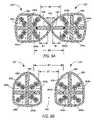
- FIG. 4Ashows an enlarged cross-sectional view of a cable according to a first embodiment of the invention.
- FIG. 4Bshows an enlarged cross-sectional view of a cable according to a second embodiment.
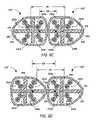
- FIG. 4Cshows an enlarged cross-sectional view of a cable according to a third embodiment.
- FIG. 4Dshows an enlarged cross-sectional view of a cable and a filler according to the embodiment of FIG. 4A in combination with a second filler.
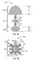
- FIG. 5Ashows an enlarged cross-sectional view of a filler according to the first embodiment of the invention.
- FIG. 5Bshows an enlarged cross-sectional view of a filler according to the third embodiment.
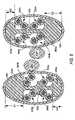
- FIG. 6Ashows a cross-sectional view of adjacent cables touching at a point of contact in accordance with the first embodiment of the invention.
- FIG. 6Bshows a cross-sectional view of the adjacent cables of FIG. 6A at a different point of contact.
- FIG. 6Cshows a cross-sectional view of the adjacent cables of FIG. 6A separated by an air pocket.
- FIG. 6Dshows a cross-sectional view of the adjacent cables of FIG. 6A separated by another air pocket.
- FIG. 7is a cross-sectional view of longitudinally adjacent cables according to the first alternate embodiment.
- FIG. 8is a cross-sectional view of longitudinally adjacent cables and fillers using the arrangement of FIG. 4D .
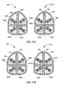
- FIG. 9Ais a cross-sectional view of the third embodiment of twisted adjacent cables configured to distance the cables' long lay length twisted pairs.
- FIG. 9Bis another cross-sectional view of the twisted adjacent cables of FIG. 9A at a different position along their longitudinally extending sections.
- FIG. 9Cis another cross-sectional view of the twisted adjacent cables of FIGS. 9A–9B at a different position along their longitudinally extending sections.
- FIG. 9Dis another cross-sectional view of the twisted adjacent cables of FIGS. 9A–9C at a different position along their longitudinally extending sections.
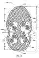
- FIG. 10shows an enlarged cross-sectional view of a cable according to a further embodiment.
- FIG. 11Ashows an enlarged cross-sectional view of adjacent cables according to the third embodiment of the invention.
- FIG. 11Bshows an enlarged cross-sectional view of the adjacent cables of FIG. 11A with a helical twist applied to each of the adjacent cables.
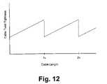
- FIG. 12shows a chart of a variation of twist rate applied over a length of the cable 120 according to one embodiment.
- the present inventionrelates in general to cables configured to accurately and efficiently propagate high-speed data signals, such as data signals approaching and surpassing data rates of 10 gigabits per second.
- the cablescan be configured to efficiently propagate the high-speed data signals while maintaining the integrity of the data signals.
- FIG. 1shows a perspective view of a cabled group, shown generally at 100 , that includes two cables 120 positioned generally along parallel axes, or longitudinally adjacent to each other.
- the cables 120are configured to create points of contact 140 and air pockets 160 between the cables 120 .
- the cables 120can be independently twisted about their own longitudinal axes.
- the cables 120may be rotated at dissimilar twist rates.
- the twist rate of each cable 120may vary over the longitudinal length of the cable 120 .
- the twist ratecan be measured by the distance of a complete twist cycle, which is referred to as lay length.
- the cables 120include elevated points along their outer edges, referred to as ridges 180 .
- the twisting of the cables 120causes the ridges 180 to helically rotate along the outer edge of each cable 120 , resulting in the formation of the air pockets 160 and the points of contact 140 at different locations along the longitudinally extending cables 120 .
- the ridges 180help maximize the distance between the cables 120 .
- the ridges 180 of the twisted cables 120help prevent the cables 120 from nesting together.
- the cables 120touch only at their ridges, which ridges 180 help increase the distance between the twisted conductor pairs 240 (not shown; see FIG. 2 ) of the cables 120 .
- the air pockets 160are formed between the cables 120 .
- the air pockets 160help increase the distance between the twisted conductor pairs 240 of the cables 120 .
- the interference between the cables 120is reduced.
- capacitive and inductive interference fieldsare known to emanate from the high-speed data signals being propagated along the cables 120 .
- the strength of the fieldsincreases with an increase in the speed of the data transmissions. Therefore, the cables 120 minimize the effects of the interference fields by increasing distances between adjacent cables 120 .
- the increased distances between the cables 120help reduce alien crosstalk between the cables 120 because the effects of alien crosstalk are inversely proportional to distance.
- the cabled group 100may include any number of cables 120 .
- the cabled group 100may include a single cable 120 .
- two cables 120are positioned along generally parallel longitudinal axes over at least a predefined distance.
- more than two cables 120are positioned along generally parallel longitudinal axes over at least the predefined distance.
- the predefined distanceis a ten meter length.
- the adjacent cables 120are independently twisted. In other embodiments, the cables 120 are twisted together.
- the cabled group 100can be used in a wide variety of communications applications.
- the cabled group 100may be configured for use in communications networks, such as a local area network (LAN) community.
- the cabled group 100is configured for use as a horizontal network cable or a backbone cable in a network community.
- the configuration of the cables 120including their individual twist rates, will be further explained below.
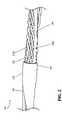
- FIG. 2shows a perspective view of an embodiment of the cable 120 , with a cutaway section exposed.
- the cable 120includes a filler 200 configured to separate a number of the twisted conductor pairs 240 (also referred to as “the twisted pairs 240 ,” “the pairs 240 ,” and “the cabled embodiments 240 ”), including twisted pair 240 a and twisted pair 240 b .
- the filler 200extends generally along a longitudinal axis, such as the longitudinal axis of one of the twisted pairs 240 .
- a jacket 260surrounds the filler 200 and the twisted pairs 240 .
- the twisted pairs 240can be independently and helically twisted about individual longitudinal axes.
- the twisted pairs 240may be distinguished from each other by being twisted at generally dissimilar twist rates, i.e., different lay lengths, over a specific longitudinal distance.
- the twisted pair 240 ais twisted more tightly than the twisted pair 240 b (i.e., the twisted pair 240 a has a shorter lay length than the twisted pair 240 b ).
- the twisted pair 240 acan be said to have a short lay length, and the twisted pair 240 b to have a long lay length.
- the twisted pair 240 a and the twisted pair 240 bminimize the number of parallel crossover points that are known to readily carry crosstalk noise.
- the cable 120includes the helically rotating ridge 180 that rotates as the cable 120 is twisted about a longitudinal axis.
- the cable 120can be twisted about the longitudinal axis at various cable lay lengths. It should be noted that the lay length of the cable 120 affects the individual lay lengths of the twisted pairs 240 . When the lay length of the cable 120 is shortened (tighter twist rate), the individual lay lengths of the twisted pairs 240 are shortened, also.
- the cable 120can be configured to beneficially affect the lay lengths of the twisted pairs 240 , which configurations will be further explained in relation to the cable 120 lay length limitations.
- FIG. 2also shows the filler 200 helically twisted about a longitudinal axis.
- the filler 200can be twisted at different or variable twist rates along a predefined distance.
- the filler 200is configured to be flexible and rigid—flexible for twisting at different twist rates and rigid for maintaining the different twist rates.
- the filler 200should be twisted enough, i.e., have a small enough lay length, to form the air pockets 160 between adjacent cables 120 .
- the filler 200is twisted at a lay length of no more than approximately one-hundred times the lay length of one of the twisted pairs 240 in order to form the air pockets 160 .
- the filler 200will be further discussed in relation to FIG. 4A .
- the filler 200 and the jacket 260can include any material that meets industry standards.
- the fillercan comprise but is not limited to any of the following: polyfluoroalkoxy, TFE/Perfluoromethyl-vinylether, ethylene chlorotrifluoroethylene, polyvinyl chloride (PVC), a lead-free flame retardant PVC, fluorinated ethylene propylene (FEP), fluorinated perfluoroethylene polypropylene, a type of fluoropolymer, flame retardant polypropylene, and other thermoplastic materials.
- the jacket 260may comprise any material that meets industry standards, including any of the materials listed above.
- the cable 120can be configured to satisfy industry standards, such as safety, electrical, and dimensional standards.
- the cable 120comprises a horizontal or backbone network cable 120 .
- the cable 120can be configured to satisfy industry safety standards for horizontal network cables 120 .
- the cable 120is plenum rated.
- the cable 120is riser rated.
- the cable 120is unshielded. The advantages generated by the configurations of the cable 120 are further explained below in reference to FIG. 4A .
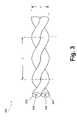
- FIG. 3is a perspective view of one of the twisted pairs 240 .
- the cabled embodiment 240includes two conductors 300 individually insulated by insulators 320 (also referred to as “insulation 320 ”).
- One conductor 300 and its surrounding insulator 320are helically twisted together with the other conductor 300 and insulator 320 down a longitudinal axis.
- FIG. 3further indicates the diameter (d) and the lay length (L) of the twisted pair 240 .
- the twisted pair 240is shielded.
- the twisted pair 240can be twisted at various lay lengths.
- the twisted pair's 240 conductors 300are twisted generally longitudinally down said axis at a specific lay length (L).
- the lay length (L) of the twisted pair 240varies over a portion or all of the longitudinal distance of the twisted pair 240 , which distance may be a predefined distance or length.
- the predefined distanceis approximately ten meters to allow enough length for correct propagation of signals as a consequence of their wavelengths.
- the twisted pair 240should conform to the industry standards, including standards governing the size of the twisted pair 240 . Accordingly, the conductors 300 and insulators 320 are configured to have good physical and electrical characteristics that at least satisfy the industry standards. It is known that a balanced twisted pair 240 helps to cancel out the interference fields that are generated in and about its active conductors 300 . Accordingly, the sizes of the conductors 300 and the insulators 320 should be configured to promote balance between the conductors 300 .
- the diameter of each of the conductors 300 and the diameter of each of the insulators 320are sized to promote balance between each single (one conductor 300 and one insulator) of the twisted pair 240 .
- the dimensions of the cable 120 components, such as the conductors 300 and the insulators 320should comply with industry standards.
- the dimensions, or size, of the cables 120 and their componentscomply with industry dimensional standards for RJ-45 cables and connectors, such as RJ-45 jacks and plugs.
- the industry dimensional standardsinclude standards for Category 5, Category 5e, and/or Category 6 cables and connectors.
- the size of the conductors 300is between #22 American Wire Gage (AWG) and #26 AWG.
- Each of the conductors 300 of the twisted pair 240can comprise any conductive material that meets industry standards, including but not limited to copper conductors 300 .
- the insulator 320may comprise but is not limited to thermoplastics, fluoropolymer materials, flame retardant polyethylene (FRPE), flame retardant polypropylene (FRPP), high density polyethylene (HDPE), polypropylene (PP), perfluoralkoxy (PFA), fluorinated ethylene propylene (FEP) in solid or foamed form, foamed ethylene-chlorotrifluoroethylene (ECTFE), and the like.
- FRPEflame retardant polyethylene
- FRPPflame retardant polypropylene
- HDPEhigh density polyethylene
- PPpolypropylene
- PFAperfluoralkoxy
- FEPfluorinated ethylene propylene
- ECTFEfoamed ethylene-chlorotrifluoroethylene
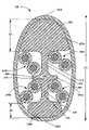
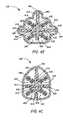
- FIG. 4Ashows an enlarged cross-sectional view of the cable 120 according to a first embodiment of the invention.
- the jacket 260surrounds the filler 200 and the twisted pairs 240 a , 240 b , 240 c , 240 d (collectively “the twisted pairs 240 ”) to form the cable 120 .
- the twisted pairs 240 a , 240 b , 240 c , 240 dcan be distinguished by having dissimilar lay lengths.
- the twisted pairs 240 a , 240 b , 240 c , 240 dmay have dissimilar lay lengths, they should be twisted in the same direction in order to minimize impedance mismatches, either all twisted pairs 240 having a right-hand twist or a left-hand twist.
- the lay lengths of the twisted pairs 240 b , 240 dare preferably similar, and the lay lengths of the twisted pairs 240 a , 240 c are preferably similar. In some embodiments, the lay lengths of the twisted pairs 240 a , 240 c are less than the lay lengths of the twisted pairs 240 b , 240 d .
- the twisted pairs 240 a , 240 ccan be referred to as the shorter lay length twisted pairs 240 a , 240 c
- the twisted pairs 240 b , 240 dcan be referred to as the longer lay length twisted pairs 240 b , 240 d
- the twisted pairs 240are shown selectively positioned in the cable 120 to minimize alien crosstalk. The selective positioning of the twisted pairs 240 will be further discussed below.
- the filler 200can be positioned along the twisted pairs 240 .
- the filler 200may form regions, such as quadrant regions, each region being configured to selectively receive and house a particular twisted pair 240 .
- the regionsform longitudinal grooves along the length of the filler 200 , which grooves can house the twisted pairs 240 .
- the filler 200can include a core 410 and a number of filler dividers 400 that extend radially outward from the core 410 .
- the core 410 of the filler 200is positioned at a point approximately central to the twisted pairs 240 .
- the filler 200further includes a number of legs 415 extending radially outward from the core 410 .
- the twisted pairs 240can be positioned adjacent to the legs 410 and/or the filler dividers 400 .
- the length of each leg 415is at least generally equal to approximately the diameter of the twisted pair 240 selectively positioned adjacent to the leg 415 .
- FIG. 5Ais an enlarged cross-sectional view of the filler 260 according to the first embodiment.
- the filler 200includes a base portion 500 that comprises the legs 415 , the dividers 400 , and the core of the filler 200 .
- the base portion 500includes any part of the filler 200 that does not extend beyond the diameter of the twisted pairs 240 , while the twisted pairs 240 are selectively housed by the regions formed by the filler 200 . Accordingly, the twisted pairs 240 should be positioned adjacent to the legs 415 of the base portion 500 of the filler 200 .
- the filler 200can include a number of filler extensions 420 a , 420 b (collectively “the filler extensions 420 ”) extending radially outward in different directions from the base portion 500 , and specifically extending from the legs 415 of the base portion 500 .
- the extension 420 to the leg 415may extend radially outward away from the base portion 500 at least a predefined extent.
- the length of the predefined extentmay be different for each extension 420 a , 420 b .
- the predefined extent of the extension 420 ais a length E 1
- the predefined extent of the extension 420 bis a length E 2 .
- the predefined extent of the extension 420is at least approximately one-quarter the diameter of one of the twisted pairs 240 housed by the filler 200 .
- the filler extension 420offsets the filler 200 , thereby helping to decrease alien crosstalk between adjacent cables 120 by maximizing the distance between the respective twisted pairs 240 of the adjacent cables 120 .
- FIG. 4Ashows a reference point 425 located at a position on each leg 415 of the filler 200 .
- the reference point 425is useful for measuring the distance between adjacently positioned cables 120 .
- the reference point 425is located at a certain length away from the core 410 of the filler 200 .
- the reference point 425is located at approximately the midpoint of each leg 415 .
- some embodimentsinclude the reference point 425 at a position that is distanced from the core 410 by approximately one-half the length of the diameter of one of the housed twisted pairs 240 .
- the filler 200may be shaped to configure the regions to fittingly house the twisted pairs 240 .
- the filler 200can include curved shapes and edges that generally fit to the shape of the twisted pairs 240 . Accordingly, the twisted pairs 240 are able to nest snugly against the filler 200 and within the regions.
- FIG. 4Ashows that the filler 200 may include concave curves configured to house the twisted pairs 240 .
- the filler 200helps to generally fix the twisted pairs 240 in position with respect to one another, thereby minimizing impedance deviations and capacitive unbalance over the length of the cable 120 , which benefit will be further discussed below.
- the filler 200can be offset.
- the filler extension 420may be configured to offset the filler 200 .
- each of the filler extensions 420extends beyond an outer edge of the cross-sectional area of at least one of the twisted pairs 240 , which length is referred to as the predefined extent.
- the extensions 420extend away from the base portion 500 .
- the filler extension 420 aextends beyond the cross-sectional area of the twisted pair 240 b and the twisted pair 240 d by the distance (E 1 ).
- the filler extension 420 bextends beyond the cross-sectional area of the twisted pair 240 a and the twisted pair 240 c by the distance (E 2 ).
- the filler extensions 420may be different lengths, e.g., the extension length (E 1 ) is greater than the extension length (E 2 ).
- the filler extension 420 ahas a cross-sectional area that is larger than the cross-sectional area of the filler extension 420 b.
- the offset filler 200helps minimize alien crosstalk.
- alien crosstalk between adjacent cables 120can be further minimized by offsetting the filler 200 by at least a minimum amount.
- the extension lengths of symmetrically positioned filler extensions 420should be different to offset the filler 200 .
- the filler 200should be offset enough to help form the air pockets 160 between helically twisted adjacent cables 120 .
- the air pockets 160should be large enough to help maintain at least an average minimum distance between adjacent cables 120 over at least a predefined length of the adjacent cables 120 .
- the offset fillers 200 of adjacent cables 120can function to distance the longer lay length twisted pairs 240 b , 240 d of one of the cables 120 farther away from outside adjacent noise sources, such as close proximity cabling embodiments, than are the shorter lay length twisted pairs 240 a , 240 c .
- the extension length (E 1 )is approximately two times the extension length (E 2 ).
- the extension length (E 1 )is approximately 0.04 inches (1.016 mm), and the extension length (E 2 ) is approximately 0.02 inches (0.508 mm).
- the longer lay length pairs 240 b , 240 dcould be placed next to the longest extension 420 a to maximize the distance between the long lay length pairs 240 b , 240 d and any outside adjacent noise sources.
- the filler extensions 420 of the cable 120preferably extend at least a minimum extension length.
- the filler extensions 420should extend beyond a cross-sectional area of the twisted pairs 240 enough to help form the air pockets 160 between adjacent cables 120 that are helically twisted, which air pockets 160 can help maintain at least an approximate minimum average distance between the adjacent cables 120 over at least the predefined length.
- At least one of the filler extensions 420extends beyond the outer edge of a cross-sectional area of at least one of the twisted pairs 240 by at least one-quarter of the diameter (d) of the same twisted pair 240 , while the twisted pair 240 is housed adjacent to the filler 200 .
- an air pocket 160is formed having a maximum extent of at least 0.1 times the diameter of a diameter of one of the cables 120 .
- the cross-sectional area of the filler 200can be enlarged to help improve the performance of the cable 200 .
- the filler extension 420 of the cable 120can be enlarged, e.g., radiused radially outward toward the jacket 260 , to help generally fix the twisted pairs 240 in position with respect to one another.
- the filler extensions 420 a , 420 bcan be expanded to comprise different cross-sectional areas. Specifically, by enlarging the cross-sectional areas of the filler 200 , the undesirable effects of impedance mismatch and capacitive unbalance are minimized, thereby making the cable 120 capable of performing at high data rates while maintaining signal integrity.
- the outer edges of the filler extensions 420can be curved to support the jacket 260 while allowing the jacket 260 to tightly fit over the filler extensions 420 .
- the curvature of the outer edges of the filler extensions 420helps to improve the performance of the cable 120 by minimizing impedance mismatches and capacitive unbalance.
- the filler extensions 420reduce the amount of air in the cable 120 and generally fix the components of the cable 120 in position, including the positions of the twisted pairs 240 with respect to one another.
- the jacket 260is compression fitted over the filler 200 and the twisted pairs 240 . The benefit of these attributes will be further discussed below.
- the filler extensions 420form the ridges 180 along the outer edge of the cable 120 .
- the ridges 180are elevated at different heights according to the lengths of the filler extensions 420 . As shown in FIG. 4A , the ridge 180 a is more elevated than the ridge 180 b . This helps to offset the cables 120 in order to reduce alien crosstalk between adjacent cables 120 , which characteristic will be further discussed below.
- a measure of the greatest diameter (D 1 ) of the cable 120is also shown in FIG. 4A .
- the diameter (D 1 )is the distance between the ridge 180 a and the ridge 180 b .
- the cable 120can be a particular size or diameter such that it complies with certain industry standards.
- the cable 120may be a size that complies with Category 5, Category 5e, and/or Category 6 unshielded cables.
- the diameter (D 1 ) of the cable 120is no more than 0.25 inches (6.35 mm).
- the cable 120can easily be used to replace existing cables.
- the cable 120can readily be substituted for a category 6 unshielded cable in a network of communication devices, thereby helping to increase the available data propagation speeds between the devices.
- the cable 120can be readily connectable with existing connector devices and schemes.
- the cable 120can help improve the communications speeds between devices of existing networks.
- FIG. 4Ashows two filler extensions 420
- other embodimentscan include various numbers and configurations of filler extensions 420 .
- Any number of filler extensions 420may be used to increase the distances between cables 120 positioned proximate to one another.
- filler extensions 420 of different or similar lengthscan be used.
- the distance provided between the adjacent cables 120 by the filler extensions 420reduces the effects of interference by increasing the distance between the cables 120 .
- the filler 200is offset to facilitate the distancing of the cables 120 as the cables 120 are individually rotated. The offset filler 200 then helps isolate a particular cable's 120 twisted pairs 240 from the alien crosstalk generated by another cable's 120 twisted pairs 240 .
- FIGS. 4B–4Cshow various different embodiments of the cable 120 .
- FIG. 4Bshows an enlarged cross-sectional view of a cable 120 ′ according to a second embodiment . . .
- the cable 120 ′ shown in FIG. 4Bincludes a filler 200 ′ that includes three legs 415 and three filler extensions 420 extending away from the legs 415 and beyond the cross-sectional areas of the twisted pairs 240 .
- Each of the legs 415includes the reference point 415 .
- the filler 200 ′can function in any of the ways discussed above in relation to the filler 200 , including helping to distance adjacently positioned cables 120 ′ from one another.
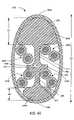
- FIG. 4Cshows an enlarged cross-sectional view of a cable 120 ′′ according to a third embodiment, which cable 120 ′′ includes a filler 200 ′′ with a number of legs 415 and one filler extension 420 extending away from one of the legs 415 and beyond the cross-sectional area of at least one of the twisted pairs 240 .
- the legs 415include the reference points 425 .
- the legs 415 shown in FIG. 4Ccan be filler dividers 400 .
- the filler 200 ′′can also function in any of the ways that the filler 200 can function.
- FIG. 5Bshows an enlarged cross-sectional view of the filler 200 ′′ according to the third embodiment.
- the filler 200 ′′can include a base portion 500 ′′ having a number of legs 415 and the extension 420 extending away from the base portion 500 ′′ and, more specifically, away from one of the legs 415 of the base portion 500 ′′.
- FIG. 5Bshows four twisted pairs 240 positioned adjacent to the base portion 500 ′′.
- the extension 420extends away from the base portion 500 ′′ by at least approximately the predefined extent.
- the filler 200 ′′includes four legs 415 with the twisted pairs 240 adjacent to the legs 415 .
- Each of the legs 415 of the base portion 500 ′′includes the reference point 425 .
- the filler 200can be configured in other ways for distancing adjacently positioned cables 120 .
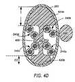
- FIG. 4Dshows an enlarged cross-sectional view of the cable 120 and the filler 200 according to the embodiment of FIG. 4A in combination with a different filler 200 ′′′′ positioned along the cable 120 .
- the filler 200 ′′′′can be helically twisted about along the cable 120 , or any component of the cable 120 .
- the filler 200 ′′′′can be positioned in between adjacently placed cables 120 and maintain a distance between them.
- the filler 200 ′′′′may be positioned along any embodiment of the cable 120 .
- the filler 200 ′′′′is positioned along the twisted pairs 240 .
- the configuration of the cables 120are able to adequately maintain the integrity of the high-speed data signals being propagated over the cables 120 .
- the cables 120are capable of such performance due to a number of features, including but not limited to the following.
- the cable configurationshelp to increase the distance between the twisted pairs 240 of adjacent cables 120 , thereby reducing the effects of alien crosstalk.
- the cables 120can be configured to increase the distance between the radiating sources that are most prone to alien crosstalk, e.g., the longer lay length twisted pairs 240 b , 240 d .
- the cables 120may be configured to help reduce the capacitive coupling between the twisted pairs 240 by improving the consistency of the dielectric properties of the materials surrounding the twisted pairs 240 .
- the cable 120can be configured to minimize the variations in impedance over its length by maintaining the physical attributes of the cable 120 components, even when the cable 120 is twisted, thereby reducing signal attenuation.
- the cables 120can be configured to reduce the number of instances of parallel twisted pairs 240 along longitudinally adjacent cables 120 , thus minimizing the occurrences of positions that are prone to alien crosstalk.
- the cables 120can be configured to minimize the degradation of propagating high-speed signals by maximizing the distance between the twisted pairs 240 of adjacent cables 120 . Specifically, the distancing of the cables 120 reduces the effects of alien crosstalk. As mentioned above, the magnitudes of the fields that cause alien crosstalk weaken with distance.
- the adjacent cables 120can be individually and helically twisted along generally parallel axes as shown in FIG. 1 such that the points of contact 140 and the air pockets 160 shown in FIG. 1 are formed at various positions along the adjacent cables 120 .
- the cables 120may be twisted so that the ridges 180 form the points of contact 140 between the cables 120 , as discussed in relation to FIG. 1 . Accordingly, at various positions along the longitudinal axes, the adjacent cables 120 may touch at their ridges 180 . At non-contact points, the adjacent cables 120 can be separated by the air pockets 160 .
- the cables 120may be configured to increase the distance between their twisted pairs 240 at both the points of contact 140 and the non-contact points, thereby reducing alien crosstalk.
- the distance between the adjacent cables 120is maximized by discouraging nesting of the adjacent cables 120 in relation to one another.
- the cables 120can be configured to maximally distance their longer lay length twisted pairs 240 b , 240 d .
- the longer lay length twisted pairs 240 b , 240 dare more prone to alien crosstalk than are the shorter lay length twisted pairs 240 a , 240 c .
- the cables 120may selectively position the longer lay length twisted pairs 240 b , 240 d proximate to the largest filler extension 420 a of each cable 120 to further distance the longer lay length twisted pairs 240 b , 240 d . This configuration will be further discussed below.
- the distance between adjacently positioned cables 120can be maximized by twisting the adjacent cables 120 at different cable lay lengths.
- the peaks of one of the adjacent cables 120do not align with the valleys of the other cable 120 , thereby discouraging a nesting alignment of the cables 120 in relation to one another.
- the different lay lengths of the adjacent cables 120help to prevent or discourage nesting of the adjacent cables 120 .
- the adjacent cables 120 shown in FIG. 1have different lay lengths. Therefore, the number and size of the air pockets 160 formed between the cables 120 are maximized.
- the cable 120can be configured to help ensure that adjacently placed sub-sections of the cable 120 do not have the same twist rate at any point along the length of the sub-sections.
- the cable 120may be helically twisted along at least a predefined length of the cable 120 .
- the helical twistingincludes a torsional rotation of the cable about a generally longitudinal axis.
- the helical twisting of the cable 120may be varied over the predefined length so that the cable lay length of the cable 120 either continuously increases or continuously decreases over the predefined length.
- the cable 120may be twisted at a certain cable lay length at a first point along the cable 120 .
- the cable lay lengthcan continuously decrease (the cable 120 is twisted tighter) along points of the cable 120 as a second point along the cable 120 is approached. As the twist of the cable 120 tightens, the distances between the spiraling ridges 180 along the cable 120 decrease. Consequently, when the predefined length of the cable 120 is separated into two sub-sections, and the sub-sections are positioned adjacent to one another, the sub-sections of the cable 120 will have different cable lay lengths. This discourages the sub-sections from nesting together because the ridges 180 of the cables 120 spiral at different rates, thereby reducing alien crosstalk between the sub-sections by maximizing the distance between them.
- the different twist rates of the sub-sectionshelp minimize alien crosstalk by maintaining a certain average distance between the sub-sections over the predefined length.
- the average distance between the closest respective reference points 425 of each of the sub-sectionsis at least one-half the distance of the length of a particular filler extension 420 (the predefined extent) of the sub-sections over the predefined length.
- the filler 200 , the twisted pairs 240 , and/or the jacket 260can be twisted correspondingly.
- the filler 200 , the twisted pairs 240 , and/or the jacket 260can be twisted such that their respective lay lengths are either continuously increased or continuously decreased over at least the predefined length.
- the jacket 260is applied over the filler 200 and twisted pairs 240 in a compression fit such that the application of the jacket 260 includes a twisting of the jacket 260 that causes the tightly received filler 200 to be twisted in a corresponding manner.
- the twisted pairs 240 received within filler 200are ultimately helically twisted with respect to one another.
- randomizing the lay lengths of the twisted pairs 240 once jacket 260 is applied such as by a twisting of the jackethas been found to have the added advantage or minimizing the re-introduction of air within cable 120 .
- other approaches to randomizationtypically increase air content, which may actually increase undesirable cross-talk. The importance of minimizing air content is discussed below in Section G.2.
- a twisting of the filler 200 independently of the jacket 260causes the twisted pairs 240 received within the filler to be helically twisted with respect to one another.
- the overall twisting of the cable 120varies an original or initial predefined lay length of each of the twisted pairs 240 .
- the twisted pairs 240are varied by approximately the same rate at each point along the predefined length.
- the ratecan be defined as the amount of torsional twist applied by the overall helical twisting of the twisted pairs 240 .
- the lay length of each of the twisted pairs 240changes a certain amount. This function and its benefits will be further discussed in relation to FIGS. 11A–11B .
- the predefined length of the cable 120will also be further discussed in relation to FIGS. 11A–11B .
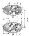
- FIGS. 6A–6Dshow various cross-sectional views of longitudinally adjacent and helically twisted cables 120 according to the first embodiment of the invention.
- FIGS. 6A–6Bshow cross-sectional views of the cables 120 touching at different points of contact 140 .
- the filler extensions 420can be configured to increase the distance between the twisted pairs 240 of adjacent cables 120 , thereby minimizing alien crosstalk at the points of contact 140 .
- the nearest twisted pairs 240 of the cables 120are separated by the distance (S 1 ).
- the distance (S 1 )equals approximately two times the sum of the extension length (E 1 ) and the thickness of the jacket 260 .
- the filler extensions 420 a of the cables 120increase the distance between the nearest twisted pairs 240 of the cables 120 by twice the extension length (E 1 ).
- the closest reference points 425 of the adjacent cables 120 shown in FIG. 6Aare separated by the distance S 1 ′.
- the adjacent cables 120are positioned such that their respective longer lay length twisted pairs 240 b , 240 d are more proximate to each other than are the shorter lay length twisted pairs 240 a , 240 c of the cables 120 . Because the longer lay length twisted pairs 240 b , 240 d are more prone to alien crosstalk than are the shorter lay length twisted pairs 240 a , 240 c , the larger filler extensions 420 a of the cables 120 are selectively positioned to provide increased distance between the longer lay length twisted pairs 240 b , 240 d of the cables 120 .
- the longer lay length twisted pairs 240 b , 240 d of the cables 120are further separated at the point of contact 140 shown in FIG. 6A , and thereby reducing alien crosstalk between them.
- the cables 120can be configured to provide maximum separation between the longer lay length twisted pairs 240 b , 240 d .
- the filler 200can selectively receive and house the twisted pairs 240 .
- the longer lay length twisted pairs 240 b , 240 dmay be positioned most proximate to a longer filler extension 420 a . This function is helpful for effectively minimizing alien crosstalk between the worst sources of alien crosstalk between the cables 120 —the longer lay length twisted pairs 240 b , 240 d.
- FIG. 6Bshows a cross-sectional view of another point of contact 140 of the cables 120 along their lengths.
- the nearest twisted pairs 240 of the cables 120are separated by the distance (S 2 ).
- the distance (S 2 )equals approximately two times the sum of the extension length (E 2 ) and the thickness of the jacket 260 .
- the filler extensions 420 b of the cables 120increase the distance between the nearest twisted pairs 240 of the cables 120 by twice the extension length (E 2 ).
- the closest reference points 425 of the adjacent cables 120 shown in FIG. 6Bare separated by the distance S 2 ′.
- the adjacent cables 120are positioned such that their respective shorter lay length twisted pairs 240 a , 240 c are more proximate to each other than are the longer lay length twisted pairs 240 b , 240 d of the cables 120 .
- the shorter lay length twisted pairs 240 a , 240 c of the cables 120are separated at the point of contact 140 shown in FIG. 6B by at least the lengths of the filler extensions 420 b , thereby reducing alien crosstalk between them.
- the smaller filler extensions 420 b of the cables 120are selectively positioned to distance the shorter lay length twisted pairs 240 a , 240 c of the cables 120 . As discussed above, increased distance is more helpful for reducing alien crosstalk between the longer lay length twisted pairs 240 b , 240 d . Therefore, the larger filler extensions 420 a of the cables 120 are used to separate the longer lay length twisted pairs 240 b , 240 d at positions where they are most proximate between the cables 120 .
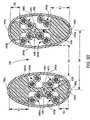
- FIGS. 6C–6Dshow cross-sectional views of the cables 120 at non-contact points along their lengths.
- the cables 120can be configured to increase the distance between the twisted pairs 240 of adjacent cables 120 by forming the air pockets 160 between the cables 120 , thereby minimizing alien crosstalk at the points of contact 140 .
- the filler extensions 420help form the air pockets 160 by helping to prevent the cables 120 from nesting together. As discussed above, this distancing effect can be maximized by creating slight fluctuations in twist rotation along the longitudinal axes of the cables 120 .
- FIG. 6Cshows a cross-sectional view of the adjacent cables 120 separated by a particular air pocket 160 at a position along their longitudinal lengths.
- the adjacent cables 120are separated by the air pocket 160 .
- the air pocket 160 formed by the helically rotating ridges 180functions to distance the most proximate twisted pairs 240 of each cable 120 .
- the length of the air pocket 160is the increased distance between the adjacent cables 120 .
- the distance between the nearest twisted pairs 240 of the cables 120 at this positionis indicated by the distance (S 3 ). Because air has excellent insulation properties, the distance formed by the air pocket 160 is effective for isolating the adjacent cables 120 from alien crosstalk.
- the closest reference points 425 of the adjacent cables 120are separated by the distance S 3 ′.
- the cables 120can be configured such that when their twisted pairs 240 are not separated by the filler extensions 420 , the air pockets 160 are formed to distance the twisted pairs 240 of the cables 120 , thereby helping to reduce alien crosstalk between the cables 120 .
- FIG. 6Dshows a cross-sectional view of the adjacent cables 120 at another air pocket 160 along their longitudinal lengths. Similar to the position shown in FIG. 6C , the cables 120 of FIG. 6D are separated by the air pocket 160 . As discussed in relation to FIG. 6C , the air pocket 160 shown in FIG. 6D functions to distance the nearest twisted pairs 240 of the cables 120 . The distance between the nearest twisted pairs 240 of the cables 120 at this position is indicated by the distance (S 4 ). In FIG. 6D , the closest reference points 425 of the adjacent cables 120 are separated by the distance S 4 ′.
- FIGS. 6A–6Dshow specific embodiments of the cables 120
- other embodiments of the cables 120can be configured to increase the distances between the twisted pairs 240 of adjacent cables 240 .
- a wide variety of filler extension 420 configurationscan be used to increase the distance between the adjacent cables 120 .
- the filler 200can include different numbers and sizes of the filler extensions 420 and the filler dividers 400 that are configured to prevent nesting of adjacent cables 120 .
- the filler 200can include any shape or design that helps to distance the adjacent cables 120 while complying with the industry standards for cable size or diameter.
- FIG. 7is a cross-sectional view of longitudinally adjacent cables 120 ′ according to the second embodiment of the invention.
- the cables 120 ′ shown in FIG. 7can be positioned similarly to the cables 120 shown in FIGS. 6A–6D .
- Each of the cables 120 ′includes the jacket 260 surrounding the filler 200 ′, the filler divider 400 , the filler extensions 420 , and the twisted pairs 240 .
- the cables 120 ′also include the ridges 180 formed along the jackets 260 by the filler extensions 420 .
- the elevated ridges 180help to increase the distance between the twisted pairs 240 of the adjacent cables 120 because the points of contact 140 between the cables 120 ′ occur at the ridges 180 of the cables 120 ′.
- each cable 120 ′includes three filler extensions 420 that extend beyond the cross-sectional areas of some of the twisted pairs 240 .
- the filler extensions 420 in FIG. 7can function in any of the ways discussed above, such as helping to prevent nesting of helically twisted adjacent cables 120 ′ and increasing the distances between the twisted pairs 240 of the cables 120 ′.
- the distance between the nearest twisted pairs 240 of the cables 120 ′ at one of the point of contact 140is indicated by the distance (S 5 ), which is approximately two times the sum of the extension length and the thickness of the jacket 260 the cable 120 ′.
- the closest reference points 425 of the adjacent cables 120 ′ shown in FIG. 7are separated by the distance S 5 ′.
- the cables 120 ′ shown in FIG. 7can selectively position the twisted pairs 240 of different lay lengths in any of the ways discussed above. Accordingly, the cables 120 ′ of FIG. 7 can be configured to minimize alien crosstalk.
- FIG. 8is an enlarged cross-sectional view of the longitudinally adjacent cables 120 and the fillers 200 ′′′′ using the arrangement of FIG. 4D .
- the cables 120 shown in FIG. 8are distanced by the helically twisting filler 200 ′′′′ in any of the ways discussed above in relation to FIG. 4D .
- the present cable configurationscan minimize signal degradation by providing for selective positioning of the twisted pairs 240 .
- the twisted pairs 240 a , 240 b , 240 c , and 240 dcan be independently twisted at dissimilar lay lengths.
- the twisted pair 240 a and the twisted pair 240 chave shorter lay lengths than the longer lay lengths of the twisted pair 240 b and the twisted pair 240 d.
- the cables 120can be configured to reduce alien crosstalk by maximizing the distance between their long lay length twisted pairs 240 b , 240 d.
- the long lay length pairs 240 b , 240 d of adjacent cables 120can be distanced by positioning them proximate to the largest filler extension 420 a .
- the extension length (E 1 ) of filler extension 420 ais greater than the extension length (E 2 ) of filler extension 420 b .
- the longer lay length twisted pairs 240are positioned more proximate to the larger filler extension 420 a than are the shorter lay length twisted pairs 240 . Accordingly, the long lay length twisted pairs 240 b , 240 d of the cables 120 are separated at the point of contact 140 by at least the greatest available extension lengths (E 1 ). This configuration and its benefits will be further explained with reference to the embodiments shown in FIGS. 9A–9D .
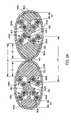
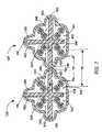
- FIGS. 9A–9Dshow cross-sectional views of longitudinally adjacent cables 120 ′′ according to the third embodiment of the inventions.
- the twisted adjacent cables 120 ′′include the long lay length twisted pairs 240 b , 240 d configured to maximize the distance between the long lay length twisted pairs 240 b , 240 d of the adjacent cables 120 ′′.
- the cables 120 ′′each include the twisted pairs 240 a , 240 b , 240 c , 240 d with dissimilar lay lengths.
- the long lay length twisted pairs 240 b , 240 dare positioned most proximate to the longest filler extension 420 of the filler 200 ′′ of each cable 120 ′′.
- FIGS. 9A–9Dshow different cross-sectional views of the twisted adjacent cables 120 ′′ at different positions along their longitudinally extending lengths.
- FIG. 9Ais a cross-sectional view of an embodiment of twisted adjacent cables 120 ′′ configured to distance the cables' 120 ′′ long lay length twisted pairs 240 b , 240 d .
- the cables 120 ′′are positioned such that the filler extensions 420 of each of the cables 120 ′′ are oriented toward each other.
- the point of contact 140is formed between the cables 120 ′′ at the ridges 180 located between the filler extensions 420 .
- the cables 120 ′′are positioned in FIG.
- the distance between the long lay twisted pairs 240 b , 240 dis approximately the sum of the lengths that the filler extensions 420 extend beyond the cross-sectional area of the twisted pairs 240 b , 240 d , indicated by the distances (E 1 ), and the jacket 260 thicknesses of each of the cables 120 ′′. This sum is indicated by the distance (S 6 ).
- the closest reference points 425 of the adjacent cables 120 ′′are separated by the distance S 6 ′.
- the configuration shown in FIG. 9Ahelps minimize alien crosstalk in any of the ways discussed above in relation to FIGS. 6A–6D .
- FIG. 9Bshows another cross-sectional view of the twisted adjacent cables 120 ′′ at another position along the lengths of the longitudinally adjacent cables 120 ′′.
- the filler extensions 420 of the cables 120 ′′are parallel and oriented generally upward. Because the filler extension 420 causes the cable 120 ′′ to be offset, the air pocket 160 is formed between the cables 120 ′′ at this orientation of the filler extensions 420 .
- the configuration shown in FIG. 9Bhelps to reduce alien crosstalk in any of the ways discussed above in relation to FIGS. 6A–6D .
- the air pocket 160helps to reduce alien crosstalk by maximizing the distance between the twisted pairs 240 of the cables 120 ′′.
- the distance (S 7 )indicates the separation between the nearest twisted pairs 240 of the cables 120 ′′.
- the closest reference points 425 of the adjacent cables 120 ′′are separated by the distance S 7 ′.
- FIG. 9Cshows another cross-sectional view of the twisted adjacent cables 120 ′′ of FIG. 9A at a different position along the lengths of the longitudinally adjacent cables 120 ′′.
- the filler extensions 420 of the cables 120 ′′are oriented away from each other.
- the long lay length twisted pairs 240 b , 240 dare selectively positioned proximate to the filler extension 420 . Accordingly, the long lay length twisted pairs 240 b , 240 d are also oriented apart.
- the short lay length twisted pairs 240 a , 240 c of each cable 120 ′′are most proximate to each other.
- the short lay length twisted pairs 240 a , 240 care not as susceptible to crosstalk as are the long lay length twisted pairs 240 b , 240 d . Therefore, the orientation of the cables 120 ′′ shown in FIG. 9C does not unacceptably harm the integrity of high-speed signals as they are propagated along the twisted pairs 240 .
- Other embodiments of the cables 120 ′′include filler extensions 420 configured to further distance the short lay length twisted pairs 240 a , 240 c.
- the long lay length twisted pairs 240 b , 240 dare naturally separated by the components of the cables 120 ′′. Specifically, the areas of the short lay length twisted pairs 240 a , 240 c of the cables 120 ′′ helps separate the long lay length twisted pairs 240 b , 240 d . Therefore, alien crosstalk is reduced at the configuration of the cables 120 ′′ shown in FIG. 9C .
- the distance between the long lay length twisted pairs 240 b , 240 d of the cables 120 ′′is indicated by the distance (S 8 ). In FIG. 9C , the closest reference points 425 of the adjacent cables 120 ′′ are separated by the distance S 8 ′.
- FIG. 9Dshows another cross-sectional view of the twisted adjacent cables 120 ′′ at another position along the lengths of the longitudinally adjacent cables 120 ′′.
- the filler extensions 420 of both cables 120 ′′are oriented in the same lateral direction.
- the long lay length twisted pairs 240 b , 240 d of each of the cables 120 ′′remain distanced apart by the distance (S 9 ), thus minimizing the effects of alien crosstalk between the long lay length twisted pairs 240 b , 240 d .
- the components of the cables 120 ′′including the short lay length twisted pairs 240 a , 240 c of one of the cables 120 ′′ helps separate the long lay length twisted pairs 240 b , 240 d of the cables 120 ′′.
- the closest reference points 425 of the adjacent cables 120 ′′are separated by the distance S 9 ′.
- the present cables 120can facilitate balanced capacitive fields about the conductors 300 of the twisted pairs 240 .
- capacitive fieldsare formed between and around the conductors 300 of a particular twisted pair 240 .
- the extent of capacitive unbalance between the conductors 300 of the twisted pair 240affects the noise emitted from the twisted pair 240 . If the capacitive fields of the conductors 300 are well-balanced, the noise produced by the fields tends to be canceled out.
- Balanceis typically promoted by insuring that the diameter of the conductors 300 and the insulators 320 of the twisted pair 240 are uniform.
- the cable 120utilizes twisted pairs 240 with uniform sizes that facilitate capacitive balance.
- the cable 120may include a number of materials positioned where they may separately affect each insulated conductor's 300 capacitance within the twisted pair 240 . This creates two different capacitances, thus creating an unbalance. This unbalance inhibits the ability of the twisted pair 240 to self-cancel noise sources, resulting in increased noise levels radiating from an active transmitting pair 240 .
- the insulator 320 , the filler 200 , the jacket 260 , and the air within the cable 120can all affect the capacitive balance of the twisted pairs 240 .
- the cable 120can be configured to include materials that help minimize any unbalancing effects, thereby maintaining the integrity of the high-speed data signals and reducing signal attenuation.
- the cable 120can minimize capacitive unbalance by using materials with consistent dielectric properties, such as consistent dielectric constants.
- the materials used for the jacket 260 , the filler 200 , and the insulators 320can be selected such that their dielectric constants are approximately the same or at least relatively close to each other.
- the jacket 260 , the filler 200 , and the insulators 320should not vary beyond a certain variation limit. When the materials of these components comprise dielectrics within the limit, capacitive unbalance is reduced, thereby maximizing noise attenuation to help maintain high-speed signal integrity.
- the dielectric constant of the filler 200 , the jacket 260 , and the insulator 320are all within approximately one dielectric constant of each other.
- the cable 120minimizes capacitive unbalance by eliminating bias that may be formed by materials with different dielectric constants positioned uniquely about the twisted pair 240 , especially in consequence of stronger capacitive fields generated by high-speed data signals.
- a particular twisted pair 24includes two conductors 300 .
- a first conductorsmay be positioned proximate to the jacket 26 while the second conductor is positioned proximate to the filler 200 . Consequently, the first conductor's 300 capacitive fields may experience more capacitive influence from the more proximate jacket 260 than from the less proximate filler 200 .
- the second conductor 300may be more biased by the filler 200 than by the jacket 260 .
- the unique biases of the conductors 300do not cancel each other out, and the capacitive fields of the twisted pair 240 are unbalanced. Further, a greater disparity between the dielectric constants of the jacket 260 and the filler 200 will undesirably increase the unbalance of the twisted pair 240 , thereby causing signal degradation.
- the cable 120can minimize the bias differences, i.e., the capacitive unbalance, by utilizing materials with consistent dielectric constants for the insulator 320 , the filler 200 , and the jacket 260 . Consequently, the capacitive fields about the conductors 300 are better balanced and result in improved noise cancellations along the length of each twisted pair within the cable 120 .
- the jacket 260may include an inner jacket and an outer jacket with dissimilar dielectric properties.
- a dielectric of the inner jacket, said filler 200 , and said insulator 320are all within approximately one dielectric constant (1) of each other.
- a dielectric of the outer jacketis not within approximately one dielectric constant of said insulator 320 .
- the predefined dimensionis a radius of approximately 0.025 inches (0.635 mm).
- the cable 120can facilitate a balance of the twisted pair's 240 overall capacitive fields by minimizing the amount of air about the twisted pair 240 .
- the amount of aircan be reduced by enlarging or otherwise maximizing the area of the filler 200 for the cable 120 .
- the area of the filler extensions 420 and/or the filler dividers 400may be increased.
- the filler extensions 420 of the cable 120are expanded toward the jacket 260 to increase the cross-sectional area of the filler extensions 420 .
- the filler 200can include edges shaped to fittingly accommodate the twisted pairs 240 , thereby minimizing the spaces in the cable 120 where air could reside.
- the filler 200includes curved edges shaped to house the twisted pairs 240 .
- the filler extensions 420may include curved outer edges configured to fittingly nest with the jacket 260 , thereby displacing air from between the filler extensions 420 and the jacket 260 when the jacket 260 is snugly or tightly fitted around the filler extensions 420 .
- the reduction in the voids of cable 120 selectively receiving a gas such as air proximate to the twisted pair 240helps minimize the materials with disparate dielectric constants. As a result, the unbalance of the twisted pair's 240 capacitive fields is minimized because biases toward uniquely positioned materials are prevented or at least attenuated. The overall effect is a decrease in the effects of noise emitted from the twisted pair 240 .
- the voids able to hold a gas such as air within the cross-sectional area of the twisted pair 240makes up less than a predetermined amount of the cross-sectional area of the twisted pair 240 or of the region housing the twisted pair 240 .
- the gas within the voidsmakes up less than the predetermined amount of the cross-sectional area of the cable 120 . In some embodiments, the amount of gas within the cable 120 is less that the predetermined amount of the volume of the cable 120 over a predefined distance. In some embodiments, the predetermined amount is ten percent.
- the cable 120has improved performance.
- the dielectrics about the twisted pairs 240are made more consistent. As discussed above, this helps reduce the noise emitted from the twisted pairs 240 . Consequently, the cables 120 are better able to accurately transmit high-speed data signals.
- FIG. 10shows a cross-sectional view of an example of an alternative embodiment of a cable 120 ′′′.
- the cable 120 ′′′ of FIG. 10shows a jacket 260 ′′′ even more tightly fitted around the twisted pairs 240 .
- the cable 120 ′′′illustrates that the jacket 260 ′′′ can be fitted around the cable 120 ′′′ in a number of different configurations that help minimize the voids able to retain a gas such as air within the cable 120 ′′′.
- the cable 120can be configured such that its components are generally fixed in position within the jacket 260 .
- the components within the jacket 260can be generally fixed by reducing the amount of air within the jacket 260 in any of the ways discussed above.
- the twisted pairs 240can be generally fixed in position with respect to one another.
- the jacket 260fits over the twisted pairs 240 in such a manner that it fixes the twisted pairs 240 in position.
- a compression fitis used, although it is not required.
- a further materialsuch as an adhesive may be used.
- the filler 200is configured to help generally fix the twisted pairs 240 in position.
- the cable 120by having fixed physical characteristics, is able to minimize impedance variations. As discussed above, any change in the physical characteristics or relations of the twisted pairs 240 is likely to result in an unwanted impedance variation. Because the cable 120 can include fixed physical attributes, the cable 120 can be manipulated, e.g., helically twisted, without introducing significant impedance deviations into the cable 120 . The cable 120 can be helically twisted after it has been jacketed without introducing hazardous impedance deviations, including during manufacture, testing, and installation procedures. Accordingly, the cable lay length of the cable 120 can be changed after it has been jacketed.
- the physical distances between the twisted pairs 240 of the cable 120do not change more than a predefined amount, even as the cable 120 is helically twisted.
- the predefined amountis approximately 0.01 inches (0.254 mm).
- the generally locked physical characteristics of the cable 120help to reduce attenuation due to signal reflections because less signal strength is reflected at any point of impedance variation along the cable 120 .
- the cable 120 configurationsfacilitate the accurate and efficient propagations of high-speed data signals by minimizing changes to the physical characteristics of the cable 120 over its length.
- materials with beneficial and consistent dielectric propertiesare used about the conductors 300 to help minimize impedance variations over the length of the cable 120 . Any variation in physical attributes of the cable 120 over its length will enhance any existing capacitive unbalance of the twisted pair 240 .
- the use of consistent dielectric materialsreduces any capacitive biases within the twisted pairs 24 . Consequently, any physical variation will enhance only minimized capacitive biases. Therefore, by using materials with consistent dielectrics proximate to the conductors 300 , the effects of any physical variation in the cable 120 are minimized.
- the present cables 120can be configured to reduce alien crosstalk by minimizing the occurrences of parallel cross-over points between adjacent cables 120 .
- parallel cross-over points between the twisted pairs 240 of the adjacent cables 120are a significant source of alien crosstalk at high-speed data rates.
- the parallel pointsoccur wherever twisted pairs 240 with identical or similar lay lengths are adjacent to each other.
- the cables 120can be twisted at dissimilar and/or varying lay lengths. When the cable 120 is helically twisted, the lay lengths of its twisted pairs 240 are changed according to the twisting of the cable 120 . Therefore, the adjacent cables 120 can be helically twisted at dissimilar overall cable 120 lay lengths in order to differentiate the lay lengths of the twisted pairs 240 of one of the cables 120 from the lay lengths of the twisted pairs 240 of adjacent cables 120 .
- FIG. 11Ashows an enlarged cross-sectional view of adjacent cables 120 - 1 according to the third embodiment of the invention.
- the adjacent cables 120 - 1 shown in FIG. 11Ainclude the twisted pairs 240 a , 240 b , 240 c , 240 d , and each twisted pair 240 having an initial predefined lay length. Assuming that neither of the cables 120 - 1 shown in FIG. 11A has been subjected to an overall helical twisting, the lay lengths of the twisted pairs 240 of the two cables 120 - 1 are the same.
- the cables 120 - 1When the cables 120 - 1 are positioned adjacent to one another, parallel cross-over points would exist between the corresponding twisted pairs 240 of the cables 120 - 1 , e.g., the twisted pairs 240 d of each of the cables 120 - 1 .
- the parallel twisted pairs 240undesirably enhance the effects of alien crosstalk between the cables 120 - 1 , especially as the cables 120 - 1 are susceptible to nesting.
- the lay lengths of the respective twisted pairs 240 of the cables 120 - 1can be made dissimilar from each other at any cross-sectional point along a predefined length of the cables 120 - 1 .
- the cables 120 - 1become different, and the initial lay lengths of their respective twisted pairs 240 are changed to resultant lay lengths.
- FIG. 11Bshows an enlarged cross-sectional view of the cables 120 - 1 of FIG. 11A after they have been twisted at different overall twist rates.
- One of the twisted cables 120 - 1is now referred to as the cable 120 - 1 ′, while the other dissimilarly twisted cables 120 - 1 is now referred to as the cable 120 - 1 ′′.
- the cable 120 - 1 ′ and the cable 120 - 1 ′′are now differentiated by their different cable lay lengths and the different resultant lay lengths of their respective twisted pairs 240 .
- the cable 120 - 1 ′includes the twisted pairs 240 a ′, 240 b ′, 240 c ′, 240 d ′ (collectively “the twisted pairs 240 ′”), which twisted pairs 240 ′ include their resultant lay lengths.
- the cable 120 - 1 ′′includes the twisted pairs 240 a ′′, 240 b ′′, 240 c ′′, 240 d ′′ (collectively “the twisted pairs 240 ′ ”) with their different resultant lay lengths.
- the adjusted, or resultant, lay lengths of the twisted pairs 240may be approximately obtained by the following formula, where “l” represents the original twisted pair 240 lay length, and “L” represents the cable lay length:
- a first of the cables 120 - 1includes the twisted pair 240 a with a predefined lay length of 0.30 inches (7.62 mm), the twisted pair 240 c with a predefined lay length of 0.40 inches (10.16 mm), the twisted pair 240 b with a predefined lay length of 0.50 inches (12.70 mm), and the twisted pair 240 d with a predefined lay length of 0.60 inches (15.24 mm).
- the predefined lay lengths of the twisted pairs 240are tightened as follows: the resultant lay length of the twisted pair 240 a ′ becomes approximately 0.279 inches (7.087 mm), the resultant lay length of the twisted pair 240 c ′ becomes approximately 0.364 inches (9.246), the resultant lay length of the twisted pair 240 b ′ becomes approximately 0.444 inches (11.278 mm), and the resultant lay length of the twisted pair 240 d ′ becomes approximately 0.522 inches (13.259 mm).
- the adjacent cables 120can be twisted randomly or non-randomly at dissimilar lay lengths, and the variation between their lay lengths can be limited within certain ranges in order to minimize the occurrences of parallel respective twisted pairs 240 between the cables 120 .
- an adjacent second cable 120 - 1can be twisted at a dissimilar overall lay length that varies at least a minimum amount from 4.00 inches (101.6 mm) so that the resultant lay lengths of its twisted pairs 240 ′′ are not too close to becoming parallel to the twisted pairs 240 ′ of the cable 120 - 1 ′.
- the second cable 120 - 1 shown in FIG. 11Acan be twisted at a lay length of 3.00 inches (76.2 mm) to become the cable 120 - 1 ′′.
- the resultant lay lengths of the cable's 120 - 1 ′′ twisted pairsbecome the following: 0.273 inches (6.934 mm) for the twisted pair 240 a ′′, 0.353 inches (8.966 mm) for the twisted pair 240 c ′′, 0.429 inches (10.897) for the twisted pair 240 b ′′, and 0.500 inches (12.7 mm) for the twisted pair 240 d ′′.
- the adjacent cables 120 - 1 shown in FIG. 11Ashould be twisted at unique lay lengths that are not too similar to each other's average cable lay lengths along at least a predefined distance, such as a ten meter cable 120 section.
- the corresponding twisted pairs 240are configured to be non-parallel or to not come within a certain range of becoming parallel.
- alien crosstalk between the cables 120is minimized because the corresponding twisted pairs 240 have dissimilar resultant lay lengths, while the corresponding twisted pairs 240 are maintained to not be too close to a parallel lay situation.
- the cable lay lengths of the adjacent cables 120vary no less than a predetermined amount of one another.
- the adjacent cables 120have individual cable lay lengths that vary no less than the predetermined amount from each other's average individual lay length calculated along at least a predefined distance of generally longitudinally extending section.
- the predetermined amountis approximately plus or minus ten percent.
- the predefined distanceis approximately ten meters.
- the adjacent cables 120can be configured to minimize alien crosstalk by having unique cable lay lengths that do not vary beyond a certain maximum variation.
- the non-corresponding respective twisted pairs 240 of the cables 120 - 1 ′, 120 - 1 ′′e.g., the twisted pair 240 b ′ of the cable 120 - 1 ′ and the twisted pair 240 d ′′ of the cable 120 - 1 ′′, are prevented from becoming approximately parallel.
- the cable lay variation limitprevents the resultant lay length of the twisted pair 240 d ′′ of the cable 120 - 1 ′′ from becoming approximately equal to the resultant lay lengths of the cable 120 - 1 ′ twisted pairs 240 a ′′, 240 b ′′, 240 c ′′.
- the lay length limitationscan be configured so that each of the twisted pair 240 ′ lay lengths of the cable 120 - 1 ′ equal no more than one of the twisted pair 240 ′′ lay lengths of the cable 120 - 1 ′′ at any cross-sectional point along the longitudinal axes of the cables 120 - 1 ′, 120 - 1 ′′.
- the limit on maximum cable lay variationkeeps the adjacent cables' 120 individual twisted pair 240 lay lengths from varying too much. If one of the adjacent cables 120 were twisted too tightly compared to the twist rate of another cable 120 , then non-corresponding twisted pairs 240 of the adjacent cables 120 may become approximately parallel, which would undesirably increase the effects of alien crosstalk between the adjacent cables 120 .
- the cable 120 - 1 ′included an overall cable lay length of 4.00 inches (101.6 mm)
- the cable 120 - 1 ′′would be twisted too tightly if it were helically twisted at a cable lay length of approximately 1.71 inches (43.434 mm).
- the resultant lay lengths of the cable's 120 - 1 ′′ twisted pairs 240 ′′become the following: 0.255 inches (6.477 mm) for the twisted pair 240 a ′′, 0.324 inches (8.230 mm) for the twisted pair 240 c ′′, 0.287 inches (7.290 mm) for the twisted pair 240 b ′′, and 0.444 inches (11.278 mm) for the twisted pair 240 d ′′.
- the cables' 120 - 1 ′, 120 - 1 ′′ corresponding twisted pairs 240 ′, 240 ′′now have a greater variation in their resultant lay lengths than they did when the cable 120 - 1 ′′ was twisted at 3.00 inches' (76.2 mm), some of the non-corresponding twisted pairs 240 ′, 240 ′′ of the cables 120 - 1 ′, 120 - 1 ′′ have become approximately parallel. This increases alien crosstalk between the cables 120 - 1 ′, 120 - 1 ′′.
- the resultant lay length of the cable's 120 - 1 ′ twisted pair 240 b ′approximately equals the resultant lay length of the cable's 120 - 1 ′′ twisted pair 240 d′′.
- the cables 120should be helically twisted such that their individual twist rates do not cause the twisted pairs 240 between the cables 120 to become approximately parallel. This is especially important when overall cable lay lengths are gradually increased or decreased within the ranges specified, as parallel conditions could be evident at some point within the range.
- the cable 120 lay lengthsmay be limited to ranges that do not cause their twisted pair 240 lay lengths to go beyond certain resultant lay length boundaries.
- the adjacent cables 120can be configured such that the resultant lay length of one of the twisted pairs 240 equals no more than one resultant twisted pair 240 lay length of the other cable 120 .
- the twisted pair 240 d of one of the adjacent cables 120will not become parallel to the twisted pairs 240 a , 24 b , and 240 c of another of the adjacent cables 120 .
- the maximum variation boundaries for the cable lay length of the cables 120is established according to maximum variation boundaries for each of the twisted pairs 240 of the cables 120 .
- a first cable 120includes the twisted pairs 240 a , 240 b , 240 c , 240 d with the following lay lengths: 0.30 inches (7.62 mm) for the twisted pair 240 a , 0.50 inches (12.7 mm) for the twisted pair 240 c , 0.70 inches (17.78 mm) for the twisted pair 240 b , and 0.90 inches (22.86 mm) for the twisted pair 240 d .
- the twist rate of the first cable 120may be limited by certain maximum variation boundaries for the lay lengths of the twisted pairs 240 of the cable 120 .
- the lay length of the first cable 120should not cause the lay length of the twisted pair 240 d to be less than 0.81 inches (20.574 mm).
- the resultant lay length of the twisted pair 240 bshould not become less than 0.61 inches (15.494 mm).
- the resultant lay length of the twisted pair 240 cshould not become less than 0.41 inches (10.414 mm).
- the cables 120can be configured to have cable lay lengths within certain minimum and maximum boundaries. Specifically, the cables 120 should each be twisted within a range bounded by a minimum variation and a maximum variation.
- the minimum variation boundaryhelps prevent the corresponding twisted pairs 240 of the cables 120 from being approximately parallel.
- the maximum variation boundaryhelps prevent the non-corresponding twisted pairs 240 of the cables 120 from becoming approximately parallel to each other, thereby reducing the effects of alien crosstalk between the cables 120 .
- the cable 120can be randomly or non-randomly twisted along at least the predefined length. Not only does this encourage distance maximization between adjacent cables 120 , it helps ensure that adjacently positioned cables 120 do not have twisted pairs 240 that are parallel to one another. At the least, the varying cable lay length of the cable 120 helps minimize the instances of parallel twisted pairs 240 . Preferably, the cable lay length of the cable 120 varies over at least the predefined length, while remaining within the maximum and the minimum cable lay variation boundaries discussed above.
- the cable 120can be helically twisted at a continuously increasing or continuously decreasing lay length so that the lay lengths of its twisted pairs are either continuously increased or continuously decreased over the predefined length such that when the predefined length of cables 120 , or the twisted pairs 240 , is separated into two sub-sections, and the sub-sections are positioned adjacent to one another, then at any point of adjacency for the sub-sections, the closest twisted pair 240 for each of the sub-sections have different lay lengths. This reduces alien crosstalk by ensuring that closest twisted pairs 240 between adjacent cables 120 have different lay lengths, i.e., are not parallel.
- FIG. 1shows two adjacent cables 120 that are individually twisted at different lay lengths.
- FIG. 12shows a chart of a variation of twist rate applied to the cable 120 according to one embodiment.
- the horizontal axisrepresents a length of the cable 120 , separated into predefined lengths.
- the vertical axisrepresents the tightness of overall cable 120 twist.
- the twist rateis continuously increased over a certain length (v) of the cable 120 , preferably over the predefined length. At the end of the certain length (1v), the twist rate quickly returns to a looser twist rate and continuously increases for at least the next predefined length (2v).
- This twist patternforms the saw-tooth chart shown in FIG. 12 .
- any section of the cable 120 along the predefined lengthcan be separated into sections, which sections do not share an identical twist rate.
- the cable lay lengthshould be varied at least over the predefined length.
- the predefined lengthequals at least approximately the length of one fundamental wavelength of a signal being transmitted over the cable 120 . This gives the fundamental wavelength enough length to complete a full cycle.
- the length of the fundamental wavelengthis dependent upon the frequency of the signal being transmitted. In some exemplary embodiments, the length of the fundamental wavelength is approximately three meters. Further, it is well known that events of a cyclical nature are additive, and multiple wavelengths are needed to see if cyclical issues exist. However, by insuring some form of randomness over a one to three wavelength distance, cyclical issues can be minimized or even potentially eliminated. In some embodiments, inspection of longer wavelengths is needed to insure randomness.
- the predefined lengthis at least approximately the length of one fundamental wavelength but no more than approximately the length of three fundamental wavelengths of a signal being transmitted. Therefore, in some embodiments, the predefined length is approximately three meters. In other embodiments, the predefined length is approximately ten meters.
- the cables 120can propagate data at throughputs approaching and surpassing 20 gigabits per second.
- the Shannon capacity of one-hundred meter length cable 120is greater than approximately 20 gigabits per second without the performance of any alien crosstalk mitigation with digital signal processing.
- the cabled group 100comprises seven cables 120 positioned longitudinally adjacent to each other over approximately a one-hundred meter length.
- the cables 120are arranged such that one centrally positioned cable 120 is surrounded by the other six cables 120 .
- the cables 120can transmit high-speed data signals at rates approaching and surpassing 20 gigabits per second.
Landscapes
- Physics & Mathematics (AREA)
- Electromagnetism (AREA)
- Communication Cables (AREA)
- Insulated Conductors (AREA)
Abstract
Description
Claims (31)
Priority Applications (5)
| Application Number | Priority Date | Filing Date | Title |
|---|---|---|---|
| US11/185,572US7329815B2 (en) | 2003-10-31 | 2005-07-19 | Cable with offset filler |
| US11/645,446US7498518B2 (en) | 2003-10-31 | 2006-12-26 | Cable with offset filler |
| US12/380,591US7875800B2 (en) | 2003-10-31 | 2009-02-27 | Cable with offset filler |
| US12/930,837US8375694B2 (en) | 2003-10-31 | 2011-01-17 | Cable with offset filler |
| US13/763,246US9142335B2 (en) | 2003-10-31 | 2013-02-08 | Cable with offset filler |
Applications Claiming Priority (3)
| Application Number | Priority Date | Filing Date | Title |
|---|---|---|---|
| US51600703P | 2003-10-31 | 2003-10-31 | |
| US10/746,800US7214884B2 (en) | 2003-10-31 | 2003-12-26 | Cable with offset filler |
| US11/185,572US7329815B2 (en) | 2003-10-31 | 2005-07-19 | Cable with offset filler |
Related Parent Applications (1)
| Application Number | Title | Priority Date | Filing Date |
|---|---|---|---|
| US10/746,800ContinuationUS7214884B2 (en) | 2003-10-31 | 2003-12-26 | Cable with offset filler |
Related Child Applications (1)
| Application Number | Title | Priority Date | Filing Date |
|---|---|---|---|
| US11/645,446ContinuationUS7498518B2 (en) | 2003-10-31 | 2006-12-26 | Cable with offset filler |
Publications (2)
| Publication Number | Publication Date |
|---|---|
| US20050247479A1 US20050247479A1 (en) | 2005-11-10 |
| US7329815B2true US7329815B2 (en) | 2008-02-12 |
Family
ID=34556074
Family Applications (8)
| Application Number | Title | Priority Date | Filing Date |
|---|---|---|---|
| US10/746,800Expired - Fee RelatedUS7214884B2 (en) | 2003-10-31 | 2003-12-26 | Cable with offset filler |
| US11/088,285Expired - Fee RelatedUS7220918B2 (en) | 2003-10-31 | 2005-03-24 | Cable with offset filler |
| US11/088,471Expired - LifetimeUS7220919B2 (en) | 2003-10-31 | 2005-03-24 | Cable with offset filler |
| US11/185,572Expired - LifetimeUS7329815B2 (en) | 2003-10-31 | 2005-07-19 | Cable with offset filler |
| US11/645,446Expired - Fee RelatedUS7498518B2 (en) | 2003-10-31 | 2006-12-26 | Cable with offset filler |
| US12/380,591Expired - Fee RelatedUS7875800B2 (en) | 2003-10-31 | 2009-02-27 | Cable with offset filler |
| US12/930,837Expired - Fee RelatedUS8375694B2 (en) | 2003-10-31 | 2011-01-17 | Cable with offset filler |
| US13/763,246Expired - Fee RelatedUS9142335B2 (en) | 2003-10-31 | 2013-02-08 | Cable with offset filler |
Family Applications Before (3)
| Application Number | Title | Priority Date | Filing Date |
|---|---|---|---|
| US10/746,800Expired - Fee RelatedUS7214884B2 (en) | 2003-10-31 | 2003-12-26 | Cable with offset filler |
| US11/088,285Expired - Fee RelatedUS7220918B2 (en) | 2003-10-31 | 2005-03-24 | Cable with offset filler |
| US11/088,471Expired - LifetimeUS7220919B2 (en) | 2003-10-31 | 2005-03-24 | Cable with offset filler |
Family Applications After (4)
| Application Number | Title | Priority Date | Filing Date |
|---|---|---|---|
| US11/645,446Expired - Fee RelatedUS7498518B2 (en) | 2003-10-31 | 2006-12-26 | Cable with offset filler |
| US12/380,591Expired - Fee RelatedUS7875800B2 (en) | 2003-10-31 | 2009-02-27 | Cable with offset filler |
| US12/930,837Expired - Fee RelatedUS8375694B2 (en) | 2003-10-31 | 2011-01-17 | Cable with offset filler |
| US13/763,246Expired - Fee RelatedUS9142335B2 (en) | 2003-10-31 | 2013-02-08 | Cable with offset filler |
Country Status (16)
| Country | Link |
|---|---|
| US (8) | US7214884B2 (en) |
| EP (1) | EP1687833B1 (en) |
| JP (1) | JP2007510275A (en) |
| KR (1) | KR101121939B1 (en) |
| AR (1) | AR046432A1 (en) |
| AU (3) | AU2004288500B2 (en) |
| BR (1) | BRPI0416098A (en) |
| CA (1) | CA2543469C (en) |
| EA (1) | EA200600874A1 (en) |
| ES (1) | ES2433494T3 (en) |
| IL (1) | IL175307A0 (en) |
| MY (1) | MY138814A (en) |
| NZ (1) | NZ546794A (en) |
| PL (1) | PL1687833T3 (en) |
| TW (1) | TWI390553B (en) |
| WO (1) | WO2005045855A1 (en) |
Cited By (180)
| Publication number | Priority date | Publication date | Assignee | Title |
|---|---|---|---|---|
| US20090266577A1 (en)* | 2003-10-31 | 2009-10-29 | Adc Incorporated | Cable with offset filler |
| US20100200269A1 (en)* | 2009-02-11 | 2010-08-12 | General Cable Technologies Corporation | Separator for communication cable with shaped ends |
| US20100218973A1 (en)* | 2009-01-30 | 2010-09-02 | Camp Ii David P | Separator for communication cable with geometric features |
| US20110005806A1 (en)* | 2004-11-17 | 2011-01-13 | Belden Cdt (Canada) Inc. | High performance telecommunications cable |
| US7964797B2 (en) | 1997-04-22 | 2011-06-21 | Belden Inc. | Data cable with striated jacket |
| US7977575B2 (en) | 1996-04-09 | 2011-07-12 | Belden Inc. | High performance data cable |
| US8030571B2 (en) | 2006-03-06 | 2011-10-04 | Belden Inc. | Web for separating conductors in a communication cable |
| US20120267144A1 (en)* | 2011-04-21 | 2012-10-25 | Bernhart Allen Gebs | Plenum Data Cable |
| US8426732B1 (en)* | 2009-06-12 | 2013-04-23 | Superior Essex Communications Lp | Communication cable with improved member for positioning signal conductors |
| US20130213686A1 (en)* | 2012-02-16 | 2013-08-22 | Qibo Jiang | Lan cable with pvc cross-filler |
| US8546693B2 (en) | 2010-08-04 | 2013-10-01 | Tyco Electronics Corporation | Cable with twisted pairs of insulated conductors and filler elements |
| US8729394B2 (en) | 1997-04-22 | 2014-05-20 | Belden Inc. | Enhanced data cable with cross-twist cabled core profile |
| US9119127B1 (en) | 2012-12-05 | 2015-08-25 | At&T Intellectual Property I, Lp | Backhaul link for distributed antenna system |
| US9154966B2 (en) | 2013-11-06 | 2015-10-06 | At&T Intellectual Property I, Lp | Surface-wave communications and methods thereof |
| US9209902B2 (en) | 2013-12-10 | 2015-12-08 | At&T Intellectual Property I, L.P. | Quasi-optical coupler |
| US9312919B1 (en) | 2014-10-21 | 2016-04-12 | At&T Intellectual Property I, Lp | Transmission device with impairment compensation and methods for use therewith |
| US9363935B1 (en) | 2006-08-11 | 2016-06-07 | Superior Essex Communications Lp | Subdivided separation fillers for use in cables |
| US9461706B1 (en) | 2015-07-31 | 2016-10-04 | At&T Intellectual Property I, Lp | Method and apparatus for exchanging communication signals |
| US9490869B1 (en) | 2015-05-14 | 2016-11-08 | At&T Intellectual Property I, L.P. | Transmission medium having multiple cores and methods for use therewith |
| US9503189B2 (en) | 2014-10-10 | 2016-11-22 | At&T Intellectual Property I, L.P. | Method and apparatus for arranging communication sessions in a communication system |
| US9509415B1 (en) | 2015-06-25 | 2016-11-29 | At&T Intellectual Property I, L.P. | Methods and apparatus for inducing a fundamental wave mode on a transmission medium |
| US9520945B2 (en) | 2014-10-21 | 2016-12-13 | At&T Intellectual Property I, L.P. | Apparatus for providing communication services and methods thereof |
| US9525210B2 (en) | 2014-10-21 | 2016-12-20 | At&T Intellectual Property I, L.P. | Guided-wave transmission device with non-fundamental mode propagation and methods for use therewith |
| US9525524B2 (en) | 2013-05-31 | 2016-12-20 | At&T Intellectual Property I, L.P. | Remote distributed antenna system |
| US9531427B2 (en) | 2014-11-20 | 2016-12-27 | At&T Intellectual Property I, L.P. | Transmission device with mode division multiplexing and methods for use therewith |
| US9564947B2 (en) | 2014-10-21 | 2017-02-07 | At&T Intellectual Property I, L.P. | Guided-wave transmission device with diversity and methods for use therewith |
| US9577307B2 (en) | 2014-10-21 | 2017-02-21 | At&T Intellectual Property I, L.P. | Guided-wave transmission device and methods for use therewith |
| US9608740B2 (en) | 2015-07-15 | 2017-03-28 | At&T Intellectual Property I, L.P. | Method and apparatus for launching a wave mode that mitigates interference |
| US9608692B2 (en) | 2015-06-11 | 2017-03-28 | At&T Intellectual Property I, L.P. | Repeater and methods for use therewith |
| US9615269B2 (en) | 2014-10-02 | 2017-04-04 | At&T Intellectual Property I, L.P. | Method and apparatus that provides fault tolerance in a communication network |
| US9628854B2 (en) | 2014-09-29 | 2017-04-18 | At&T Intellectual Property I, L.P. | Method and apparatus for distributing content in a communication network |
| US9628116B2 (en) | 2015-07-14 | 2017-04-18 | At&T Intellectual Property I, L.P. | Apparatus and methods for transmitting wireless signals |
| US9640850B2 (en) | 2015-06-25 | 2017-05-02 | At&T Intellectual Property I, L.P. | Methods and apparatus for inducing a non-fundamental wave mode on a transmission medium |
| US9654173B2 (en) | 2014-11-20 | 2017-05-16 | At&T Intellectual Property I, L.P. | Apparatus for powering a communication device and methods thereof |
| US9653770B2 (en) | 2014-10-21 | 2017-05-16 | At&T Intellectual Property I, L.P. | Guided wave coupler, coupling module and methods for use therewith |
| US9667317B2 (en) | 2015-06-15 | 2017-05-30 | At&T Intellectual Property I, L.P. | Method and apparatus for providing security using network traffic adjustments |
| US9680670B2 (en) | 2014-11-20 | 2017-06-13 | At&T Intellectual Property I, L.P. | Transmission device with channel equalization and control and methods for use therewith |
| US9685992B2 (en) | 2014-10-03 | 2017-06-20 | At&T Intellectual Property I, L.P. | Circuit panel network and methods thereof |
| US9692101B2 (en) | 2014-08-26 | 2017-06-27 | At&T Intellectual Property I, L.P. | Guided wave couplers for coupling electromagnetic waves between a waveguide surface and a surface of a wire |
| US9705561B2 (en) | 2015-04-24 | 2017-07-11 | At&T Intellectual Property I, L.P. | Directional coupling device and methods for use therewith |
| US9705571B2 (en) | 2015-09-16 | 2017-07-11 | At&T Intellectual Property I, L.P. | Method and apparatus for use with a radio distributed antenna system |
| US9722318B2 (en) | 2015-07-14 | 2017-08-01 | At&T Intellectual Property I, L.P. | Method and apparatus for coupling an antenna to a device |
| US9729197B2 (en) | 2015-10-01 | 2017-08-08 | At&T Intellectual Property I, L.P. | Method and apparatus for communicating network management traffic over a network |
| US9735833B2 (en) | 2015-07-31 | 2017-08-15 | At&T Intellectual Property I, L.P. | Method and apparatus for communications management in a neighborhood network |
| US9742462B2 (en) | 2014-12-04 | 2017-08-22 | At&T Intellectual Property I, L.P. | Transmission medium and communication interfaces and methods for use therewith |
| US9741470B1 (en) | 2017-03-10 | 2017-08-22 | Superior Essex International LP | Communication cables incorporating separators with longitudinally spaced projections |
| US9749013B2 (en) | 2015-03-17 | 2017-08-29 | At&T Intellectual Property I, L.P. | Method and apparatus for reducing attenuation of electromagnetic waves guided by a transmission medium |
| US9748626B2 (en) | 2015-05-14 | 2017-08-29 | At&T Intellectual Property I, L.P. | Plurality of cables having different cross-sectional shapes which are bundled together to form a transmission medium |
| US9749053B2 (en) | 2015-07-23 | 2017-08-29 | At&T Intellectual Property I, L.P. | Node device, repeater and methods for use therewith |
| US9755697B2 (en) | 2014-09-15 | 2017-09-05 | At&T Intellectual Property I, L.P. | Method and apparatus for sensing a condition in a transmission medium of electromagnetic waves |
| US9762289B2 (en) | 2014-10-14 | 2017-09-12 | At&T Intellectual Property I, L.P. | Method and apparatus for transmitting or receiving signals in a transportation system |
| US9769020B2 (en) | 2014-10-21 | 2017-09-19 | At&T Intellectual Property I, L.P. | Method and apparatus for responding to events affecting communications in a communication network |
| US9769128B2 (en) | 2015-09-28 | 2017-09-19 | At&T Intellectual Property I, L.P. | Method and apparatus for encryption of communications over a network |
| US9780834B2 (en) | 2014-10-21 | 2017-10-03 | At&T Intellectual Property I, L.P. | Method and apparatus for transmitting electromagnetic waves |
| US9793951B2 (en) | 2015-07-15 | 2017-10-17 | At&T Intellectual Property I, L.P. | Method and apparatus for launching a wave mode that mitigates interference |
| US9793954B2 (en) | 2015-04-28 | 2017-10-17 | At&T Intellectual Property I, L.P. | Magnetic coupling device and methods for use therewith |
| US9793955B2 (en) | 2015-04-24 | 2017-10-17 | At&T Intellectual Property I, Lp | Passive electrical coupling device and methods for use therewith |
| US9800327B2 (en) | 2014-11-20 | 2017-10-24 | At&T Intellectual Property I, L.P. | Apparatus for controlling operations of a communication device and methods thereof |
| US9820146B2 (en) | 2015-06-12 | 2017-11-14 | At&T Intellectual Property I, L.P. | Method and apparatus for authentication and identity management of communicating devices |
| US9836957B2 (en) | 2015-07-14 | 2017-12-05 | At&T Intellectual Property I, L.P. | Method and apparatus for communicating with premises equipment |
| US9838896B1 (en) | 2016-12-09 | 2017-12-05 | At&T Intellectual Property I, L.P. | Method and apparatus for assessing network coverage |
| US9847566B2 (en) | 2015-07-14 | 2017-12-19 | At&T Intellectual Property I, L.P. | Method and apparatus for adjusting a field of a signal to mitigate interference |
| US9847850B2 (en) | 2014-10-14 | 2017-12-19 | At&T Intellectual Property I, L.P. | Method and apparatus for adjusting a mode of communication in a communication network |
| US9853342B2 (en) | 2015-07-14 | 2017-12-26 | At&T Intellectual Property I, L.P. | Dielectric transmission medium connector and methods for use therewith |
| US9860075B1 (en) | 2016-08-26 | 2018-01-02 | At&T Intellectual Property I, L.P. | Method and communication node for broadband distribution |
| US9866309B2 (en) | 2015-06-03 | 2018-01-09 | At&T Intellectual Property I, Lp | Host node device and methods for use therewith |
| US9865911B2 (en) | 2015-06-25 | 2018-01-09 | At&T Intellectual Property I, L.P. | Waveguide system for slot radiating first electromagnetic waves that are combined into a non-fundamental wave mode second electromagnetic wave on a transmission medium |
| US9871283B2 (en) | 2015-07-23 | 2018-01-16 | At&T Intellectual Property I, Lp | Transmission medium having a dielectric core comprised of plural members connected by a ball and socket configuration |
| US9871282B2 (en) | 2015-05-14 | 2018-01-16 | At&T Intellectual Property I, L.P. | At least one transmission medium having a dielectric surface that is covered at least in part by a second dielectric |
| US9876570B2 (en) | 2015-02-20 | 2018-01-23 | At&T Intellectual Property I, Lp | Guided-wave transmission device with non-fundamental mode propagation and methods for use therewith |
| US9876264B2 (en) | 2015-10-02 | 2018-01-23 | At&T Intellectual Property I, Lp | Communication system, guided wave switch and methods for use therewith |
| US9876605B1 (en) | 2016-10-21 | 2018-01-23 | At&T Intellectual Property I, L.P. | Launcher and coupling system to support desired guided wave mode |
| US9882277B2 (en) | 2015-10-02 | 2018-01-30 | At&T Intellectual Property I, Lp | Communication device and antenna assembly with actuated gimbal mount |
| US9882257B2 (en) | 2015-07-14 | 2018-01-30 | At&T Intellectual Property I, L.P. | Method and apparatus for launching a wave mode that mitigates interference |
| US9893795B1 (en) | 2016-12-07 | 2018-02-13 | At&T Intellectual Property I, Lp | Method and repeater for broadband distribution |
| US9904535B2 (en) | 2015-09-14 | 2018-02-27 | At&T Intellectual Property I, L.P. | Method and apparatus for distributing software |
| US9906269B2 (en) | 2014-09-17 | 2018-02-27 | At&T Intellectual Property I, L.P. | Monitoring and mitigating conditions in a communication network |
| US9912419B1 (en) | 2016-08-24 | 2018-03-06 | At&T Intellectual Property I, L.P. | Method and apparatus for managing a fault in a distributed antenna system |
| US9912027B2 (en) | 2015-07-23 | 2018-03-06 | At&T Intellectual Property I, L.P. | Method and apparatus for exchanging communication signals |
| US9911020B1 (en) | 2016-12-08 | 2018-03-06 | At&T Intellectual Property I, L.P. | Method and apparatus for tracking via a radio frequency identification device |
| US9912381B2 (en) | 2015-06-03 | 2018-03-06 | At&T Intellectual Property I, Lp | Network termination and methods for use therewith |
| US9913139B2 (en) | 2015-06-09 | 2018-03-06 | At&T Intellectual Property I, L.P. | Signal fingerprinting for authentication of communicating devices |
| US9917341B2 (en) | 2015-05-27 | 2018-03-13 | At&T Intellectual Property I, L.P. | Apparatus and method for launching electromagnetic waves and for modifying radial dimensions of the propagating electromagnetic waves |
| US9928943B1 (en) | 2016-08-03 | 2018-03-27 | Superior Essex International LP | Communication cables incorporating separator structures |
| US9927517B1 (en) | 2016-12-06 | 2018-03-27 | At&T Intellectual Property I, L.P. | Apparatus and methods for sensing rainfall |
| US9948333B2 (en) | 2015-07-23 | 2018-04-17 | At&T Intellectual Property I, L.P. | Method and apparatus for wireless communications to mitigate interference |
| US9948354B2 (en) | 2015-04-28 | 2018-04-17 | At&T Intellectual Property I, L.P. | Magnetic coupling device with reflective plate and methods for use therewith |
| US9954287B2 (en) | 2014-11-20 | 2018-04-24 | At&T Intellectual Property I, L.P. | Apparatus for converting wireless signals and electromagnetic waves and methods thereof |
| US9967173B2 (en) | 2015-07-31 | 2018-05-08 | At&T Intellectual Property I, L.P. | Method and apparatus for authentication and identity management of communicating devices |
| US9973940B1 (en) | 2017-02-27 | 2018-05-15 | At&T Intellectual Property I, L.P. | Apparatus and methods for dynamic impedance matching of a guided wave launcher |
| US9991580B2 (en) | 2016-10-21 | 2018-06-05 | At&T Intellectual Property I, L.P. | Launcher and coupling system for guided wave mode cancellation |
| US9999038B2 (en) | 2013-05-31 | 2018-06-12 | At&T Intellectual Property I, L.P. | Remote distributed antenna system |
| US9998870B1 (en) | 2016-12-08 | 2018-06-12 | At&T Intellectual Property I, L.P. | Method and apparatus for proximity sensing |
| US9997819B2 (en) | 2015-06-09 | 2018-06-12 | At&T Intellectual Property I, L.P. | Transmission medium and method for facilitating propagation of electromagnetic waves via a core |
| US10009065B2 (en) | 2012-12-05 | 2018-06-26 | At&T Intellectual Property I, L.P. | Backhaul link for distributed antenna system |
| US10009901B2 (en) | 2015-09-16 | 2018-06-26 | At&T Intellectual Property I, L.P. | Method, apparatus, and computer-readable storage medium for managing utilization of wireless resources between base stations |
| US10009067B2 (en) | 2014-12-04 | 2018-06-26 | At&T Intellectual Property I, L.P. | Method and apparatus for configuring a communication interface |
| US10009063B2 (en) | 2015-09-16 | 2018-06-26 | At&T Intellectual Property I, L.P. | Method and apparatus for use with a radio distributed antenna system having an out-of-band reference signal |
| US10020587B2 (en) | 2015-07-31 | 2018-07-10 | At&T Intellectual Property I, L.P. | Radial antenna and methods for use therewith |
| US10020844B2 (en) | 2016-12-06 | 2018-07-10 | T&T Intellectual Property I, L.P. | Method and apparatus for broadcast communication via guided waves |
| US10027397B2 (en) | 2016-12-07 | 2018-07-17 | At&T Intellectual Property I, L.P. | Distributed antenna system and methods for use therewith |
| US10033108B2 (en) | 2015-07-14 | 2018-07-24 | At&T Intellectual Property I, L.P. | Apparatus and methods for generating an electromagnetic wave having a wave mode that mitigates interference |
| US10033107B2 (en) | 2015-07-14 | 2018-07-24 | At&T Intellectual Property I, L.P. | Method and apparatus for coupling an antenna to a device |
| US10044409B2 (en) | 2015-07-14 | 2018-08-07 | At&T Intellectual Property I, L.P. | Transmission medium and methods for use therewith |
| US10051629B2 (en) | 2015-09-16 | 2018-08-14 | At&T Intellectual Property I, L.P. | Method and apparatus for use with a radio distributed antenna system having an in-band reference signal |
| US10051483B2 (en) | 2015-10-16 | 2018-08-14 | At&T Intellectual Property I, L.P. | Method and apparatus for directing wireless signals |
| US10069535B2 (en) | 2016-12-08 | 2018-09-04 | At&T Intellectual Property I, L.P. | Apparatus and methods for launching electromagnetic waves having a certain electric field structure |
| US10068685B1 (en) | 2016-11-08 | 2018-09-04 | Superior Essex International LP | Communication cables with separators having alternating projections |
| US10074890B2 (en) | 2015-10-02 | 2018-09-11 | At&T Intellectual Property I, L.P. | Communication device and antenna with integrated light assembly |
| US10079661B2 (en) | 2015-09-16 | 2018-09-18 | At&T Intellectual Property I, L.P. | Method and apparatus for use with a radio distributed antenna system having a clock reference |
| US10090606B2 (en) | 2015-07-15 | 2018-10-02 | At&T Intellectual Property I, L.P. | Antenna system with dielectric array and methods for use therewith |
| US10090594B2 (en) | 2016-11-23 | 2018-10-02 | At&T Intellectual Property I, L.P. | Antenna system having structural configurations for assembly |
| US10103422B2 (en) | 2016-12-08 | 2018-10-16 | At&T Intellectual Property I, L.P. | Method and apparatus for mounting network devices |
| US10103801B2 (en) | 2015-06-03 | 2018-10-16 | At&T Intellectual Property I, L.P. | Host node device and methods for use therewith |
| US10121571B1 (en) | 2016-08-31 | 2018-11-06 | Superior Essex International LP | Communications cables incorporating separator structures |
| US10135147B2 (en) | 2016-10-18 | 2018-11-20 | At&T Intellectual Property I, L.P. | Apparatus and methods for launching guided waves via an antenna |
| US10135146B2 (en) | 2016-10-18 | 2018-11-20 | At&T Intellectual Property I, L.P. | Apparatus and methods for launching guided waves via circuits |
| US10136434B2 (en) | 2015-09-16 | 2018-11-20 | At&T Intellectual Property I, L.P. | Method and apparatus for use with a radio distributed antenna system having an ultra-wideband control channel |
| US10135145B2 (en) | 2016-12-06 | 2018-11-20 | At&T Intellectual Property I, L.P. | Apparatus and methods for generating an electromagnetic wave along a transmission medium |
| US10142086B2 (en) | 2015-06-11 | 2018-11-27 | At&T Intellectual Property I, L.P. | Repeater and methods for use therewith |
| US10139820B2 (en) | 2016-12-07 | 2018-11-27 | At&T Intellectual Property I, L.P. | Method and apparatus for deploying equipment of a communication system |
| US10148016B2 (en) | 2015-07-14 | 2018-12-04 | At&T Intellectual Property I, L.P. | Apparatus and methods for communicating utilizing an antenna array |
| US10144036B2 (en) | 2015-01-30 | 2018-12-04 | At&T Intellectual Property I, L.P. | Method and apparatus for mitigating interference affecting a propagation of electromagnetic waves guided by a transmission medium |
| US10154493B2 (en) | 2015-06-03 | 2018-12-11 | At&T Intellectual Property I, L.P. | Network termination and methods for use therewith |
| US10170840B2 (en) | 2015-07-14 | 2019-01-01 | At&T Intellectual Property I, L.P. | Apparatus and methods for sending or receiving electromagnetic signals |
| US10168695B2 (en) | 2016-12-07 | 2019-01-01 | At&T Intellectual Property I, L.P. | Method and apparatus for controlling an unmanned aircraft |
| US10178445B2 (en) | 2016-11-23 | 2019-01-08 | At&T Intellectual Property I, L.P. | Methods, devices, and systems for load balancing between a plurality of waveguides |
| US10205655B2 (en) | 2015-07-14 | 2019-02-12 | At&T Intellectual Property I, L.P. | Apparatus and methods for communicating utilizing an antenna array and multiple communication paths |
| US10224634B2 (en) | 2016-11-03 | 2019-03-05 | At&T Intellectual Property I, L.P. | Methods and apparatus for adjusting an operational characteristic of an antenna |
| US10225025B2 (en) | 2016-11-03 | 2019-03-05 | At&T Intellectual Property I, L.P. | Method and apparatus for detecting a fault in a communication system |
| US10243784B2 (en) | 2014-11-20 | 2019-03-26 | At&T Intellectual Property I, L.P. | System for generating topology information and methods thereof |
| US10243270B2 (en) | 2016-12-07 | 2019-03-26 | At&T Intellectual Property I, L.P. | Beam adaptive multi-feed dielectric antenna system and methods for use therewith |
| US10264586B2 (en) | 2016-12-09 | 2019-04-16 | At&T Mobility Ii Llc | Cloud-based packet controller and methods for use therewith |
| US10276281B1 (en) | 2016-11-08 | 2019-04-30 | Superior Essex International LP | Communication cables with twisted tape separators |
| US10291334B2 (en) | 2016-11-03 | 2019-05-14 | At&T Intellectual Property I, L.P. | System for detecting a fault in a communication system |
| US10291311B2 (en) | 2016-09-09 | 2019-05-14 | At&T Intellectual Property I, L.P. | Method and apparatus for mitigating a fault in a distributed antenna system |
| US10298293B2 (en) | 2017-03-13 | 2019-05-21 | At&T Intellectual Property I, L.P. | Apparatus of communication utilizing wireless network devices |
| US10305190B2 (en) | 2016-12-01 | 2019-05-28 | At&T Intellectual Property I, L.P. | Reflecting dielectric antenna system and methods for use therewith |
| US10312567B2 (en) | 2016-10-26 | 2019-06-04 | At&T Intellectual Property I, L.P. | Launcher with planar strip antenna and methods for use therewith |
| US10320586B2 (en) | 2015-07-14 | 2019-06-11 | At&T Intellectual Property I, L.P. | Apparatus and methods for generating non-interfering electromagnetic waves on an insulated transmission medium |
| US10326689B2 (en) | 2016-12-08 | 2019-06-18 | At&T Intellectual Property I, L.P. | Method and system for providing alternative communication paths |
| US10326494B2 (en) | 2016-12-06 | 2019-06-18 | At&T Intellectual Property I, L.P. | Apparatus for measurement de-embedding and methods for use therewith |
| US10340573B2 (en) | 2016-10-26 | 2019-07-02 | At&T Intellectual Property I, L.P. | Launcher with cylindrical coupling device and methods for use therewith |
| US10340603B2 (en) | 2016-11-23 | 2019-07-02 | At&T Intellectual Property I, L.P. | Antenna system having shielded structural configurations for assembly |
| US10340983B2 (en) | 2016-12-09 | 2019-07-02 | At&T Intellectual Property I, L.P. | Method and apparatus for surveying remote sites via guided wave communications |
| US10340601B2 (en) | 2016-11-23 | 2019-07-02 | At&T Intellectual Property I, L.P. | Multi-antenna system and methods for use therewith |
| US10341142B2 (en) | 2015-07-14 | 2019-07-02 | At&T Intellectual Property I, L.P. | Apparatus and methods for generating non-interfering electromagnetic waves on an uninsulated conductor |
| US10340600B2 (en) | 2016-10-18 | 2019-07-02 | At&T Intellectual Property I, L.P. | Apparatus and methods for launching guided waves via plural waveguide systems |
| US10348391B2 (en) | 2015-06-03 | 2019-07-09 | At&T Intellectual Property I, L.P. | Client node device with frequency conversion and methods for use therewith |
| US10355367B2 (en) | 2015-10-16 | 2019-07-16 | At&T Intellectual Property I, L.P. | Antenna structure for exchanging wireless signals |
| US10359749B2 (en) | 2016-12-07 | 2019-07-23 | At&T Intellectual Property I, L.P. | Method and apparatus for utilities management via guided wave communication |
| US10361489B2 (en) | 2016-12-01 | 2019-07-23 | At&T Intellectual Property I, L.P. | Dielectric dish antenna system and methods for use therewith |
| US10374316B2 (en) | 2016-10-21 | 2019-08-06 | At&T Intellectual Property I, L.P. | System and dielectric antenna with non-uniform dielectric |
| US10382976B2 (en) | 2016-12-06 | 2019-08-13 | At&T Intellectual Property I, L.P. | Method and apparatus for managing wireless communications based on communication paths and network device positions |
| US10389029B2 (en) | 2016-12-07 | 2019-08-20 | At&T Intellectual Property I, L.P. | Multi-feed dielectric antenna system with core selection and methods for use therewith |
| US10389037B2 (en) | 2016-12-08 | 2019-08-20 | At&T Intellectual Property I, L.P. | Apparatus and methods for selecting sections of an antenna array and use therewith |
| US10396887B2 (en) | 2015-06-03 | 2019-08-27 | At&T Intellectual Property I, L.P. | Client node device and methods for use therewith |
| US10411356B2 (en) | 2016-12-08 | 2019-09-10 | At&T Intellectual Property I, L.P. | Apparatus and methods for selectively targeting communication devices with an antenna array |
| US10438726B1 (en) | 2017-06-16 | 2019-10-08 | Superior Essex International LP | Communication cables incorporating separators with longitudinally spaced radial ridges |
| US10439675B2 (en) | 2016-12-06 | 2019-10-08 | At&T Intellectual Property I, L.P. | Method and apparatus for repeating guided wave communication signals |
| US10446936B2 (en) | 2016-12-07 | 2019-10-15 | At&T Intellectual Property I, L.P. | Multi-feed dielectric antenna system and methods for use therewith |
| US10498044B2 (en) | 2016-11-03 | 2019-12-03 | At&T Intellectual Property I, L.P. | Apparatus for configuring a surface of an antenna |
| US10530505B2 (en) | 2016-12-08 | 2020-01-07 | At&T Intellectual Property I, L.P. | Apparatus and methods for launching electromagnetic waves along a transmission medium |
| US10535928B2 (en) | 2016-11-23 | 2020-01-14 | At&T Intellectual Property I, L.P. | Antenna system and methods for use therewith |
| US10547348B2 (en) | 2016-12-07 | 2020-01-28 | At&T Intellectual Property I, L.P. | Method and apparatus for switching transmission mediums in a communication system |
| US10601494B2 (en) | 2016-12-08 | 2020-03-24 | At&T Intellectual Property I, L.P. | Dual-band communication device and method for use therewith |
| US10637149B2 (en) | 2016-12-06 | 2020-04-28 | At&T Intellectual Property I, L.P. | Injection molded dielectric antenna and methods for use therewith |
| US10650940B2 (en) | 2015-05-15 | 2020-05-12 | At&T Intellectual Property I, L.P. | Transmission medium having a conductive material and methods for use therewith |
| US10665942B2 (en) | 2015-10-16 | 2020-05-26 | At&T Intellectual Property I, L.P. | Method and apparatus for adjusting wireless communications |
| US10679767B2 (en) | 2015-05-15 | 2020-06-09 | At&T Intellectual Property I, L.P. | Transmission medium having a conductive material and methods for use therewith |
| US10694379B2 (en) | 2016-12-06 | 2020-06-23 | At&T Intellectual Property I, L.P. | Waveguide system with device-based authentication and methods for use therewith |
| US10727599B2 (en) | 2016-12-06 | 2020-07-28 | At&T Intellectual Property I, L.P. | Launcher with slot antenna and methods for use therewith |
| US10755542B2 (en) | 2016-12-06 | 2020-08-25 | At&T Intellectual Property I, L.P. | Method and apparatus for surveillance via guided wave communication |
| US10777873B2 (en) | 2016-12-08 | 2020-09-15 | At&T Intellectual Property I, L.P. | Method and apparatus for mounting network devices |
| US10784670B2 (en) | 2015-07-23 | 2020-09-22 | At&T Intellectual Property I, L.P. | Antenna support for aligning an antenna |
| US10811767B2 (en) | 2016-10-21 | 2020-10-20 | At&T Intellectual Property I, L.P. | System and dielectric antenna with convex dielectric radome |
| US10819035B2 (en) | 2016-12-06 | 2020-10-27 | At&T Intellectual Property I, L.P. | Launcher with helical antenna and methods for use therewith |
| US10916969B2 (en) | 2016-12-08 | 2021-02-09 | At&T Intellectual Property I, L.P. | Method and apparatus for providing power using an inductive coupling |
| US10938108B2 (en) | 2016-12-08 | 2021-03-02 | At&T Intellectual Property I, L.P. | Frequency selective multi-feed dielectric antenna system and methods for use therewith |
| US11032819B2 (en) | 2016-09-15 | 2021-06-08 | At&T Intellectual Property I, L.P. | Method and apparatus for use with a radio distributed antenna system having a control channel reference signal |
Families Citing this family (68)
| Publication number | Priority date | Publication date | Assignee | Title |
|---|---|---|---|---|
| US7405360B2 (en) | 1997-04-22 | 2008-07-29 | Belden Technologies, Inc. | Data cable with cross-twist cabled core profile |
| US7712108B2 (en)* | 2003-12-08 | 2010-05-04 | Microsoft Corporation | Media processing methods, systems and application program interfaces |
| US7652211B2 (en)* | 2004-01-23 | 2010-01-26 | E. I. Du Pont De Nemours And Company | Plenum cable |
| US20050221678A1 (en) | 2004-02-20 | 2005-10-06 | Hammond Bernard Jr | Methods and systems for compensating for alien crosstalk between connectors |
| US10680385B2 (en) | 2004-02-20 | 2020-06-09 | Commscope Technologies Llc | Methods and systems for compensating for alien crosstalk between connectors |
| US7157644B2 (en) | 2004-12-16 | 2007-01-02 | General Cable Technology Corporation | Reduced alien crosstalk electrical cable with filler element |
| US7317163B2 (en)* | 2004-12-16 | 2008-01-08 | General Cable Technology Corp. | Reduced alien crosstalk electrical cable with filler element |
| US7238885B2 (en)* | 2004-12-16 | 2007-07-03 | Panduit Corp. | Reduced alien crosstalk electrical cable with filler element |
| US7345243B2 (en) | 2004-12-17 | 2008-03-18 | Panduit Corp. | Communication cable with variable lay length |
| US7208683B2 (en)* | 2005-01-28 | 2007-04-24 | Belden Technologies, Inc. | Data cable for mechanically dynamic environments |
| JP4758444B2 (en)* | 2005-01-31 | 2011-08-31 | パンドウィット・コーポレーション | Ethernet connector pin placement direction |
| EP1688968A1 (en)* | 2005-02-04 | 2006-08-09 | Nexans | Helical electrical cable |
| US7390971B2 (en)* | 2005-04-29 | 2008-06-24 | Nexans | Unsheilded twisted pair cable and method for manufacturing the same |
| KR100690117B1 (en)* | 2005-07-28 | 2007-03-08 | 엘에스전선 주식회사 | Communication cable having an outer spacer and method of manufacturing the same |
| KR100782229B1 (en)* | 2005-08-30 | 2007-12-05 | 엘에스전선 주식회사 | Communication cable with separator and spacer integrated inside |
| US7145080B1 (en) | 2005-11-08 | 2006-12-05 | Hitachi Cable Manchester, Inc. | Off-set communications cable |
| CA2631883A1 (en)* | 2005-12-09 | 2007-06-14 | Belden Technologies, Inc. | Twisted pair cable having improved crosstalk isolation |
| US7271342B2 (en)* | 2005-12-22 | 2007-09-18 | Adc Telecommunications, Inc. | Cable with twisted pair centering arrangement |
| US7271344B1 (en)* | 2006-03-09 | 2007-09-18 | Adc Telecommunications, Inc. | Multi-pair cable with channeled jackets |
| US7602695B2 (en)* | 2006-05-31 | 2009-10-13 | Current Technologies, Llc | System and method for communicating in a multi-unit structure |
| US7375284B2 (en)* | 2006-06-21 | 2008-05-20 | Adc Telecommunications, Inc. | Multi-pair cable with varying lay length |
| US7413466B2 (en)* | 2006-08-29 | 2008-08-19 | Adc Telecommunications, Inc. | Threaded connector and patch cord having a threaded connector |
| US7817444B2 (en) | 2006-11-30 | 2010-10-19 | Adc Gmbh | Detachable cable manager |
| AU312804S (en) | 2006-11-30 | 2007-02-07 | Tyco Electronics Services Gmbh | Detachable cable manager |
| US7550674B2 (en)* | 2007-02-22 | 2009-06-23 | Nexans | UTP cable |
| AU2007201105B2 (en) | 2007-03-14 | 2011-08-04 | Tyco Electronics Services Gmbh | Electrical Connector |
| AU2007201109B2 (en)* | 2007-03-14 | 2010-11-04 | Tyco Electronics Services Gmbh | Electrical Connector |
| AU2007201108B2 (en)* | 2007-03-14 | 2012-02-09 | Tyco Electronics Services Gmbh | Electrical Connector |
| AU2007201106B9 (en)* | 2007-03-14 | 2011-06-02 | Tyco Electronics Services Gmbh | Electrical Connector |
| AU2007201113B2 (en) | 2007-03-14 | 2011-09-08 | Tyco Electronics Services Gmbh | Electrical Connector |
| AU2007201102B2 (en)* | 2007-03-14 | 2010-11-04 | Tyco Electronics Services Gmbh | Electrical Connector |
| AU2007201107B2 (en) | 2007-03-14 | 2011-06-23 | Tyco Electronics Services Gmbh | Electrical Connector |
| AU2007201114B2 (en)* | 2007-03-14 | 2011-04-07 | Tyco Electronics Services Gmbh | Electrical Connector |
| KR100825408B1 (en)* | 2007-04-13 | 2008-04-29 | 엘에스전선 주식회사 | High-speed communication cable |
| KR100951051B1 (en) | 2007-05-17 | 2010-04-05 | 엘에스전선 주식회사 | Cable for high speed communication |
| US20100209058A1 (en)* | 2007-06-18 | 2010-08-19 | Ott Michael J | Fiber optic telecommunications system |
| HK1117341A2 (en)* | 2007-11-14 | 2009-01-09 | Clipsal Australia Pty Limited | Multi-conductor cable construction |
| US7897875B2 (en) | 2007-11-19 | 2011-03-01 | Belden Inc. | Separator spline and cables using same |
| EP2131370B1 (en)* | 2008-06-02 | 2011-09-07 | Nexans | Helically-wound electric cable |
| KR101070501B1 (en)* | 2008-09-25 | 2011-10-05 | 엘에스전선 주식회사 | A Data Communication Cable |
| US8344255B2 (en)* | 2009-01-16 | 2013-01-01 | Adc Telecommunications, Inc. | Cable with jacket including a spacer |
| FR2949274B1 (en)* | 2009-08-19 | 2012-03-23 | Nexans | DATA COMMUNICATION CABLE |
| US8785782B2 (en)* | 2010-01-08 | 2014-07-22 | Hyundai Mobis Co., Ltd | UTP cable of improved alien crosstalk characteristic |
| US8625946B2 (en)* | 2010-03-11 | 2014-01-07 | Adc Telecommunications, Inc. | Optical fiber assembly |
| US8818156B2 (en) | 2010-03-30 | 2014-08-26 | Corning Cable Systems Llc | Multiple channel optical fiber furcation tube and cable assembly using same |
| US8907211B2 (en) | 2010-10-29 | 2014-12-09 | Jamie M. Fox | Power cable with twisted and untwisted wires to reduce ground loop voltages |
| US9355755B2 (en) | 2011-04-07 | 2016-05-31 | 3M Innovative Properties Company | High speed transmission cable |
| US20120312579A1 (en) | 2011-06-10 | 2012-12-13 | Kenny Robert D | Cable jacket with embedded shield and method for making the same |
| US8684763B2 (en) | 2011-06-21 | 2014-04-01 | Adc Telecommunications, Inc. | Connector with slideable retention feature and patch cord having the same |
| WO2012177486A2 (en) | 2011-06-21 | 2012-12-27 | Adc Telecommunications, Inc. | Connector with cable retention feature and patch cord having the same |
| US11336058B2 (en) | 2013-03-14 | 2022-05-17 | Aptiv Technologies Limited | Shielded cable assembly |
| DE102013227051B4 (en)* | 2013-12-20 | 2017-03-30 | Leoni Kabel Holding Gmbh | Measuring arrangement and method for temperature measurement and sensor cable for such a measuring arrangement |
| US10818412B2 (en) | 2016-03-31 | 2020-10-27 | Autonetworks Technologies, Ltd. | Communication cable |
| JP6075490B1 (en) | 2016-03-31 | 2017-02-08 | 株式会社オートネットワーク技術研究所 | Shield wire for communication |
| US11347069B2 (en) | 2016-11-22 | 2022-05-31 | Lumentum Operations Llc | Rotary optical beam generator |
| US10690855B2 (en) | 2016-11-22 | 2020-06-23 | Lumentum Operations Llc | Tapered non-concentric core fibers |
| US10656334B2 (en) | 2016-11-22 | 2020-05-19 | Lumentum Operations Llc | Rotary optical beam generator |
| US10429584B2 (en)* | 2016-11-22 | 2019-10-01 | Lumentum Operations Llc | Rotary optical beam generator |
| NL2018988B1 (en)* | 2017-05-29 | 2018-12-07 | Use System Eng Holding B V | Twisted pair cable and CEDD system comprising such a cable |
| KR102478382B1 (en)* | 2017-08-25 | 2022-12-15 | 엘에스전선 주식회사 | Twisted Pair Cable |
| US10553333B2 (en)* | 2017-09-28 | 2020-02-04 | Sterlite Technologies Limited | I-shaped filler |
| CN107958728A (en)* | 2017-10-17 | 2018-04-24 | 安徽庆华电缆有限公司 | Intrinsic safety type polyethylene insulation pair twist pvc sheath shields flame retardant computer cable |
| WO2020210075A1 (en)* | 2019-04-08 | 2020-10-15 | Commscope Technologies Llc | Low cost extrudable isolator from slit-tape |
| US12131847B2 (en)* | 2019-12-06 | 2024-10-29 | Sumitomo Electric Industries, Ltd. | Multicore cable |
| EP4147253A1 (en)* | 2020-05-07 | 2023-03-15 | Belden Inc. | Shield-supporting filler for data communications cables |
| US11682501B2 (en)* | 2020-09-22 | 2023-06-20 | Belden Inc. | Hybrid high frequency separator with parametric control ratios of conductive components |
| US12014847B2 (en)* | 2021-12-03 | 2024-06-18 | Aptiv Technologies AG | Cable for connecting system components |
| CN114783674A (en)* | 2022-05-04 | 2022-07-22 | 安徽华通电缆集团有限公司 | Special high corrosion-resistant flame-retardant intrinsically safe computer cable for petrochemical plants and its forming equipment |
Citations (117)
| Publication number | Priority date | Publication date | Assignee | Title |
|---|---|---|---|---|
| US483285A (en) | 1892-09-27 | auilleaume | ||
| US1389143A (en)* | 1919-01-25 | 1921-08-30 | Westinghouse Electric & Mfg Co | Reinforced tube and method of making it |
| US1475139A (en) | 1920-03-30 | 1923-11-20 | George C Pearson | Telephone cable |
| US1977209A (en) | 1930-12-09 | 1934-10-16 | Macintosh Cable Company Ltd | Electric cable |
| US2204737A (en) | 1937-10-14 | 1940-06-18 | Ici Ltd | Manufacture of electric cables |
| US2556244A (en) | 1945-09-07 | 1951-06-12 | Int Standard Electric Corp | Coaxial cable with helically wound spacer |
| US2583026A (en) | 1949-08-12 | 1952-01-22 | Simplex Wire & Cable Co | Cable with interlocked insulating layers |
| CA524452A (en) | 1956-05-01 | Anaconda Wire And Cable Company | High frequency cable | |
| US2804494A (en) | 1953-04-08 | 1957-08-27 | Charles F Fenton | High frequency transmission cable |
| US2959102A (en) | 1956-12-04 | 1960-11-08 | Taylor Taylor & Hobson Ltd | Optical objectives |
| US3025656A (en) | 1957-07-17 | 1962-03-20 | Cook Foundation Inc | Method and apparatus for making communication cable |
| US3052079A (en) | 1958-11-10 | 1962-09-04 | Western Electric Co | Apparatus for twisting strands |
| US3209064A (en)* | 1961-10-19 | 1965-09-28 | Communications Patents Ltd | Signal transmission electric cables |
| US3603715A (en) | 1968-12-07 | 1971-09-07 | Kabel Metallwerke Ghh | Arrangement for supporting one or several superconductors in the interior of a cryogenic cable |
| US3621118A (en) | 1970-07-31 | 1971-11-16 | Anaconda Wire & Cable Co | Power cable for portable machines |
| US3736366A (en) | 1972-04-27 | 1973-05-29 | Bell Telephone Labor Inc | Mass bonding of twisted pair cables |
| US3847190A (en) | 1972-12-19 | 1974-11-12 | Phillips Cable Ltd | Method and apparatus for twisting wires |
| US3921381A (en) | 1972-03-17 | 1975-11-25 | Siemens Ag | Method of manufacturing a cable using SZ twisting devices |
| US3927247A (en) | 1968-10-07 | 1975-12-16 | Belden Corp | Shielded coaxial cable |
| DE2459844A1 (en) | 1974-12-18 | 1976-07-01 | Felten & Guilleaume Kabelwerk | ELECTRICAL LINE |
| US4102117A (en) | 1976-06-25 | 1978-07-25 | Western Electric Company, Inc. | Wire twisting method and apparatus |
| US4263471A (en) | 1979-01-03 | 1981-04-21 | Les Cables De Lyon | Cable for digital transmission |
| US4319940A (en) | 1979-10-31 | 1982-03-16 | Bell Telephone Laboratories, Incorporated | Methods of making cable having superior resistance to flame spread and smoke evolution |
| US4372105A (en) | 1979-08-02 | 1983-02-08 | Western Electric Company, Inc. | Reverse oscillated lay cable |
| US4408443A (en) | 1981-11-05 | 1983-10-11 | Western Electric Company, Inc. | Telecommunications cable and method of making same |
| US4413469A (en) | 1981-03-23 | 1983-11-08 | Allied Corporation | Method of making low crosstalk ribbon cable |
| US4654476A (en) | 1984-02-15 | 1987-03-31 | Siemens Aktiengesellschaft | Flexible multiconductor electric cable |
| US4683349A (en) | 1984-11-29 | 1987-07-28 | Norichika Takebe | Elastic electric cable |
| US4687294A (en) | 1984-05-25 | 1987-08-18 | Cooper Industries, Inc. | Fiber optic plenum cable |
| US4755629A (en) | 1985-09-27 | 1988-07-05 | At&T Technologies | Local area network cable |
| US4807962A (en) | 1986-03-06 | 1989-02-28 | American Telephone And Telegraph Company, At&T Bell Laboratories | Optical fiber cable having fluted strength member core |
| US5042904A (en) | 1990-07-18 | 1991-08-27 | Comm/Scope, Inc. | Communications cable and method having a talk path in an enhanced cable jacket |
| US5132488A (en) | 1991-02-21 | 1992-07-21 | Northern Telecom Limited | Electrical telecommunications cable |
| US5177809A (en) | 1990-12-19 | 1993-01-05 | Siemens Aktiengesellschaft | Optical cable having a plurality of light waveguides |
| JPH05101711A (en) | 1991-10-08 | 1993-04-23 | Oki Densen Kk | Low electrostatic capacity type insulated wire |
| US5263309A (en) | 1992-05-11 | 1993-11-23 | Southwire Company | Method of and apparatus for balancing the load of a cabling apparatus |
| US5286923A (en) | 1990-11-14 | 1994-02-15 | Filotex | Electric cable having high propagation velocity |
| US5289556A (en) | 1992-09-23 | 1994-02-22 | Northern Telecom Limited | Optical fiber units and optical cables |
| US5298680A (en) | 1992-08-07 | 1994-03-29 | Kenny Robert D | Dual twisted pairs over single jacket |
| JPH06349344A (en) | 1993-06-04 | 1994-12-22 | Furukawa Electric Co Ltd:The | Communication cable |
| US5399813A (en) | 1993-06-24 | 1995-03-21 | The Whitaker Corporation | Category 5 telecommunication cable |
| US5424491A (en) | 1993-10-08 | 1995-06-13 | Northern Telecom Limited | Telecommunications cable |
| US5493071A (en) | 1994-11-10 | 1996-02-20 | Berk-Tek, Inc. | Communication cable for use in a plenum |
| US5514837A (en) | 1995-03-28 | 1996-05-07 | Belden Wire & Cable Company | Plenum cable |
| US5525757A (en) | 1995-03-15 | 1996-06-11 | Belden Wire & Cable Co. | Flame retardant polyolefin wire insulations |
| US5535579A (en) | 1992-04-30 | 1996-07-16 | Southwire Company | Method and apparatus for controlling takeup tension on a stranded conductor as it is being formed |
| US5544270A (en) | 1995-03-07 | 1996-08-06 | Mohawk Wire And Cable Corp. | Multiple twisted pair data cable with concentric cable groups |
| US5564268A (en) | 1994-04-08 | 1996-10-15 | Ceeco Machinery Manufacturing Ltd. | Apparatus and method for the manufacture of uniform impedance communication cables for high frequency use |
| US5565653A (en) | 1993-09-09 | 1996-10-15 | Filotex | High frequency transmission cable |
| US5574250A (en) | 1995-02-03 | 1996-11-12 | W. L. Gore & Associates, Inc. | Multiple differential pair cable |
| US5597981A (en) | 1994-11-09 | 1997-01-28 | Hitachi Cable, Ltd. | Unshielded twisted pair cable |
| US5600097A (en) | 1994-11-04 | 1997-02-04 | Lucent Technologies Inc. | Fire resistant cable for use in local area network |
| US5606151A (en) | 1993-03-17 | 1997-02-25 | Belden Wire & Cable Company | Twisted parallel cable |
| US5614319A (en) | 1995-05-04 | 1997-03-25 | Commscope, Inc. | Insulating composition, insulated plenum cable and methods for making same |
| US5659152A (en) | 1994-03-14 | 1997-08-19 | The Furukawa Electric Co., Ltd. | Communication cable |
| US5706642A (en) | 1996-10-08 | 1998-01-13 | Haselwander; Jack G. | Variable twist level yarn |
| US5739473A (en) | 1995-07-31 | 1998-04-14 | Lucent Technologies Inc. | Fire resistant cable for use in local area network |
| US5742002A (en) | 1995-07-20 | 1998-04-21 | Andrew Corporation | Air-dielectric coaxial cable with hollow spacer element |
| US5744757A (en) | 1995-03-28 | 1998-04-28 | Belden Wire & Cable Company | Plenum cable |
| US5763823A (en) | 1996-01-12 | 1998-06-09 | Belden Wire & Cable Company | Patch cable for high-speed LAN applications |
| US5767441A (en) | 1996-01-04 | 1998-06-16 | General Cable Industries | Paired electrical cable having improved transmission properties and method for making same |
| US5770820A (en) | 1995-03-15 | 1998-06-23 | Belden Wire & Cable Co | Plenum cable |
| US5789711A (en) | 1996-04-09 | 1998-08-04 | Belden Wire & Cable Company | High-performance data cable |
| US5814768A (en) | 1996-06-03 | 1998-09-29 | Commscope, Inc. | Twisted pairs communications cable |
| US5821466A (en) | 1996-12-23 | 1998-10-13 | Cable Design Technologies, Inc. | Multiple twisted pair data cable with geometrically concentric cable groups |
| US5902962A (en) | 1997-04-15 | 1999-05-11 | Gazdzinski; Robert F. | Cable and method of monitoring cable aging |
| US5922155A (en) | 1996-04-23 | 1999-07-13 | Filotex | Method and device for manufacturing an insulative material cellular insulator around a conductor and coaxial cable provided with an insulator of this kind |
| US5952615A (en) | 1995-09-15 | 1999-09-14 | Filotex | Multiple pair cable with individually shielded pairs that is easy to connect |
| US5952607A (en) | 1997-01-31 | 1999-09-14 | Lucent Technologies Inc. | Local area network cabling arrangement |
| US5966917A (en) | 1998-02-11 | 1999-10-19 | Nextrom, Ltd. | Pre-twist group twinner and method of manufacturing communication cables for high frequency use |
| US5969295A (en) | 1998-01-09 | 1999-10-19 | Commscope, Inc. Of North Carolina | Twisted pair communications cable |
| US5990419A (en) | 1996-08-26 | 1999-11-23 | Virginia Patent Development Corporation | Data cable |
| US6074503A (en) | 1997-04-22 | 2000-06-13 | Cable Design Technologies, Inc. | Making enhanced data cable with cross-twist cabled core profile |
| US6091025A (en) | 1997-07-29 | 2000-07-18 | Khamsin Technologies, Llc | Electrically optimized hybird "last mile" telecommunications cable system |
| US6096977A (en) | 1998-09-04 | 2000-08-01 | Lucent Technologies Inc. | High speed transmission patch cord cable |
| US6139957A (en) | 1998-08-28 | 2000-10-31 | Commscope, Inc. Of North Carolina | Conductor insulated with foamed fluoropolymer and method of making same |
| US6150612A (en) | 1998-04-17 | 2000-11-21 | Prestolite Wire Corporation | High performance data cable |
| US6153826A (en) | 1999-05-28 | 2000-11-28 | Prestolite Wire Corporation | Optimizing lan cable performance |
| US6194663B1 (en) | 1997-02-28 | 2001-02-27 | Lucent Technologies Inc. | Local area network cabling arrangement |
| US6211467B1 (en) | 1998-08-06 | 2001-04-03 | Prestolite Wire Corporation | Low loss data cable |
| US6222129B1 (en) | 1993-03-17 | 2001-04-24 | Belden Wire & Cable Company | Twisted pair cable |
| US6222130B1 (en) | 1996-04-09 | 2001-04-24 | Belden Wire & Cable Company | High performance data cable |
| WO2001041158A1 (en) | 1999-12-02 | 2001-06-07 | Belden Wire & Cable Company | A cable separator spline |
| US6248954B1 (en) | 1999-02-25 | 2001-06-19 | Cable Design Technologies, Inc. | Multi-pair data cable with configurable core filling and pair separation |
| US6259031B1 (en) | 1998-08-06 | 2001-07-10 | Krone Digital Communications | Cable with twisting filler |
| US6300573B1 (en) | 1999-07-12 | 2001-10-09 | The Furukawa Electric Co., Ltd. | Communication cable |
| US6318062B1 (en) | 1998-11-13 | 2001-11-20 | Watson Machinery International, Inc. | Random lay wire twisting machine |
| US6323427B1 (en) | 1999-05-28 | 2001-11-27 | Krone, Inc. | Low delay skew multi-pair cable and method of manufacture |
| US6342678B1 (en) | 1998-03-12 | 2002-01-29 | Nexans | Low-crosstalk flexible cable |
| US6348651B1 (en) | 2000-03-27 | 2002-02-19 | Hon Hai Precision Ind. Co., Ltd. | Twist pattern to improve electrical performances of twisted-pair cable |
| US6355876B1 (en) | 1999-09-27 | 2002-03-12 | Sumitomo Wiring Systems, Ltd. | Twisted-pair cable and method of making a twisted-pair cable |
| US6378283B1 (en) | 2000-05-25 | 2002-04-30 | Helix/Hitemp Cables, Inc. | Multiple conductor electrical cable with minimized crosstalk |
| US6392152B1 (en) | 1996-04-30 | 2002-05-21 | Belden Communications | Plenum cable |
| JP2002157926A (en) | 2000-11-17 | 2002-05-31 | Sumitomo Wiring Syst Ltd | Twisted pair cable |
| EP1215688A1 (en)* | 2000-12-13 | 2002-06-19 | Sagem SA | High frequency telecom cable with groups of wire-conductors |
| US6433272B1 (en) | 2000-09-19 | 2002-08-13 | Storage Technology Corporation | Crosstalk reduction in constrained wiring assemblies |
| US6452094B2 (en) | 1999-06-03 | 2002-09-17 | Lucent Technologies Inc. | High speed transmission local area network cable |
| US6476323B2 (en) | 2001-02-26 | 2002-11-05 | Federal-Mogul Systems Protection Group, Inc. | Rigidized protective sleeving |
| US6495762B2 (en) | 2000-07-11 | 2002-12-17 | Servicios Condumex S.A. De C.V. | Multipurpose cable for outside telecommunications |
| JP2002367446A (en) | 2001-06-07 | 2002-12-20 | Yazaki Corp | UTP cable |
| US6506976B1 (en) | 1999-09-14 | 2003-01-14 | Avaya Technology Corp. | Electrical cable apparatus and method for making |
| US6566607B1 (en) | 1999-10-05 | 2003-05-20 | Nordx/Cdt, Inc. | High speed data communication cables |
| US6624359B2 (en) | 2001-12-14 | 2003-09-23 | Neptco Incorporated | Multifolded composite tape for use in cable manufacture and methods for making same |
| US6639152B2 (en) | 2001-08-25 | 2003-10-28 | Cable Components Group, Llc | High performance support-separator for communications cable |
| US6684030B1 (en) | 1997-07-29 | 2004-01-27 | Khamsin Technologies, Llc | Super-ring architecture and method to support high bandwidth digital “last mile” telecommunications systems for unlimited video addressability in hub/star local loop architectures |
| US20040055781A1 (en)* | 2002-03-13 | 2004-03-25 | Nordx/Cdt, Inc. | Twisted pair cable with cable separator |
| US6770819B2 (en) | 2002-02-12 | 2004-08-03 | Commscope, Properties Llc | Communications cables with oppositely twinned and bunched insulated conductors |
| US20040149484A1 (en) | 2003-02-05 | 2004-08-05 | William Clark | Multi-pair communication cable using different twist lay lengths and pair proximity control |
| US6787697B2 (en) | 2000-01-19 | 2004-09-07 | Belden Wire & Cable Company | Cable channel filler with imbedded shield and cable containing the same |
| US6800811B1 (en) | 2000-06-09 | 2004-10-05 | Commscope Properties, Llc | Communications cables with isolators |
| US6812408B2 (en) | 1999-02-25 | 2004-11-02 | Cable Design Technologies, Inc. | Multi-pair data cable with configurable core filling and pair separation |
| US6818832B2 (en) | 2002-02-26 | 2004-11-16 | Commscope Solutions Properties, Llc | Network cable with elliptical crossweb fin structure |
| US20050006132A1 (en) | 1997-04-22 | 2005-01-13 | Cable Design Technologies Inc., Dba Mohawk/Cdt | Data cable with cross-twist cabled core profile |
| US20050045367A1 (en) | 2002-10-16 | 2005-03-03 | Somers Steve L. | UTP cable apparatus with nonconducting core, and method of making same |
| US6875928B1 (en) | 2003-10-23 | 2005-04-05 | Commscope Solutions Properties, Llc | Local area network cabling arrangement with randomized variation |
| US20050103518A1 (en) | 2003-04-15 | 2005-05-19 | Cable Components Group, Llc | Support separators for high performance communications cable with optional hollow tubes for; blown optical fiber, coaxial, and/or twisted pair conductors |
| US6959533B2 (en) | 2002-01-10 | 2005-11-01 | International Business Machines Corporation | Apparatus and method for producing twisted pair cables with reduced propagation delay and crosstalk |
Family Cites Families (15)
| Publication number | Priority date | Publication date | Assignee | Title |
|---|---|---|---|---|
| US1997209A (en)* | 1933-11-02 | 1935-04-09 | Harry A Douglas | Control mechanism |
| GB1322893A (en)* | 1969-07-10 | 1973-07-11 | Molins Machine Co Ltd | Applying of adhesives |
| US4381426A (en)* | 1981-03-23 | 1983-04-26 | Allied Corporation | Low crosstalk ribbon cable |
| JPS58214219A (en) | 1982-06-04 | 1983-12-13 | 吉田工業株式会社 | Random pitch twisted wire and method of producing same |
| JPS62202417A (en)* | 1986-02-28 | 1987-09-07 | タツタ電線株式会社 | variable pitch cable |
| JPS62216110A (en)* | 1986-03-14 | 1987-09-22 | タツタ電線株式会社 | Variable pitch cable |
| US5162609A (en)* | 1991-07-31 | 1992-11-10 | At&T Bell Laboratories | Fire-resistant cable for transmitting high frequency signals |
| JPH10149728A (en) | 1996-11-19 | 1998-06-02 | Sumitomo Wiring Syst Ltd | Electric cable |
| CA2291649C (en)* | 1998-12-03 | 2002-07-09 | Omar Saad | Double-twisting cable machine and cable formed therewith |
| US6321013B1 (en) | 1999-09-15 | 2001-11-20 | Lucent Technologies, Inc. | Stacks of optical fiber ribbons closely bound by respective buffer encasements, associated methods, and associated fiber optic cables |
| JP4477729B2 (en)* | 2000-01-19 | 2010-06-09 | シャープ株式会社 | Photoelectric conversion element and solar cell using the same |
| JP2004289373A (en) | 2003-03-20 | 2004-10-14 | Tdk Corp | Wireless communication system, wireless terminal device, and method for switching communication system |
| US7392647B2 (en) | 2003-10-23 | 2008-07-01 | Commscope, Inc. Of North Carolina | Methods and apparatus for forming cable media |
| US7214884B2 (en) | 2003-10-31 | 2007-05-08 | Adc Incorporated | Cable with offset filler |
| US7115815B2 (en)* | 2003-10-31 | 2006-10-03 | Adc Telecommunications, Inc. | Cable utilizing varying lay length mechanisms to minimize alien crosstalk |
- 2003
- 2003-12-26USUS10/746,800patent/US7214884B2/ennot_activeExpired - Fee Related
- 2004
- 2004-10-14EAEA200600874Apatent/EA200600874A1/enunknown
- 2004-10-14NZNZ546794Apatent/NZ546794A/ennot_activeIP Right Cessation
- 2004-10-14KRKR20067010673Apatent/KR101121939B1/ennot_activeExpired - Fee Related
- 2004-10-14BRBRPI0416098-3Apatent/BRPI0416098A/ennot_activeApplication Discontinuation
- 2004-10-14JPJP2006538066Apatent/JP2007510275A/enactivePending
- 2004-10-14ESES04795260Tpatent/ES2433494T3/ennot_activeExpired - Lifetime
- 2004-10-14EPEP20040795260patent/EP1687833B1/ennot_activeExpired - Lifetime
- 2004-10-14PLPL04795260Tpatent/PL1687833T3/enunknown
- 2004-10-14AUAU2004288500Apatent/AU2004288500B2/ennot_activeCeased
- 2004-10-14CACA 2543469patent/CA2543469C/ennot_activeExpired - Fee Related
- 2004-10-14WOPCT/US2004/034073patent/WO2005045855A1/enactiveApplication Filing
- 2004-10-22TWTW93132178Apatent/TWI390553B/ennot_activeIP Right Cessation
- 2004-10-26MYMYPI20044416patent/MY138814A/enunknown
- 2004-10-29ARARP040103963patent/AR046432A1/enunknown
- 2005
- 2005-03-24USUS11/088,285patent/US7220918B2/ennot_activeExpired - Fee Related
- 2005-03-24USUS11/088,471patent/US7220919B2/ennot_activeExpired - Lifetime
- 2005-07-19USUS11/185,572patent/US7329815B2/ennot_activeExpired - Lifetime
- 2006
- 2006-04-27ILIL175307Apatent/IL175307A0/enunknown
- 2006-12-26USUS11/645,446patent/US7498518B2/ennot_activeExpired - Fee Related
- 2009
- 2009-02-27USUS12/380,591patent/US7875800B2/ennot_activeExpired - Fee Related
- 2010
- 2010-06-01AUAU2010202261Apatent/AU2010202261B2/ennot_activeCeased
- 2010-06-01AUAU2010202260Apatent/AU2010202260B2/ennot_activeCeased
- 2011
- 2011-01-17USUS12/930,837patent/US8375694B2/ennot_activeExpired - Fee Related
- 2013
- 2013-02-08USUS13/763,246patent/US9142335B2/ennot_activeExpired - Fee Related
Patent Citations (124)
| Publication number | Priority date | Publication date | Assignee | Title |
|---|---|---|---|---|
| CA524452A (en) | 1956-05-01 | Anaconda Wire And Cable Company | High frequency cable | |
| US483285A (en) | 1892-09-27 | auilleaume | ||
| US1389143A (en)* | 1919-01-25 | 1921-08-30 | Westinghouse Electric & Mfg Co | Reinforced tube and method of making it |
| US1475139A (en) | 1920-03-30 | 1923-11-20 | George C Pearson | Telephone cable |
| US1977209A (en) | 1930-12-09 | 1934-10-16 | Macintosh Cable Company Ltd | Electric cable |
| US2204737A (en) | 1937-10-14 | 1940-06-18 | Ici Ltd | Manufacture of electric cables |
| US2556244A (en) | 1945-09-07 | 1951-06-12 | Int Standard Electric Corp | Coaxial cable with helically wound spacer |
| US2583026A (en) | 1949-08-12 | 1952-01-22 | Simplex Wire & Cable Co | Cable with interlocked insulating layers |
| US2804494A (en) | 1953-04-08 | 1957-08-27 | Charles F Fenton | High frequency transmission cable |
| US2959102A (en) | 1956-12-04 | 1960-11-08 | Taylor Taylor & Hobson Ltd | Optical objectives |
| US3025656A (en) | 1957-07-17 | 1962-03-20 | Cook Foundation Inc | Method and apparatus for making communication cable |
| US3052079A (en) | 1958-11-10 | 1962-09-04 | Western Electric Co | Apparatus for twisting strands |
| US3209064A (en)* | 1961-10-19 | 1965-09-28 | Communications Patents Ltd | Signal transmission electric cables |
| US3927247A (en) | 1968-10-07 | 1975-12-16 | Belden Corp | Shielded coaxial cable |
| US3603715A (en) | 1968-12-07 | 1971-09-07 | Kabel Metallwerke Ghh | Arrangement for supporting one or several superconductors in the interior of a cryogenic cable |
| US3621118A (en) | 1970-07-31 | 1971-11-16 | Anaconda Wire & Cable Co | Power cable for portable machines |
| US3921381A (en) | 1972-03-17 | 1975-11-25 | Siemens Ag | Method of manufacturing a cable using SZ twisting devices |
| US3736366A (en) | 1972-04-27 | 1973-05-29 | Bell Telephone Labor Inc | Mass bonding of twisted pair cables |
| US3847190A (en) | 1972-12-19 | 1974-11-12 | Phillips Cable Ltd | Method and apparatus for twisting wires |
| DE2459844A1 (en) | 1974-12-18 | 1976-07-01 | Felten & Guilleaume Kabelwerk | ELECTRICAL LINE |
| US4102117A (en) | 1976-06-25 | 1978-07-25 | Western Electric Company, Inc. | Wire twisting method and apparatus |
| US4263471A (en) | 1979-01-03 | 1981-04-21 | Les Cables De Lyon | Cable for digital transmission |
| US4372105A (en) | 1979-08-02 | 1983-02-08 | Western Electric Company, Inc. | Reverse oscillated lay cable |
| US4319940A (en) | 1979-10-31 | 1982-03-16 | Bell Telephone Laboratories, Incorporated | Methods of making cable having superior resistance to flame spread and smoke evolution |
| US4413469A (en) | 1981-03-23 | 1983-11-08 | Allied Corporation | Method of making low crosstalk ribbon cable |
| US4408443A (en) | 1981-11-05 | 1983-10-11 | Western Electric Company, Inc. | Telecommunications cable and method of making same |
| US4654476A (en) | 1984-02-15 | 1987-03-31 | Siemens Aktiengesellschaft | Flexible multiconductor electric cable |
| US4687294A (en) | 1984-05-25 | 1987-08-18 | Cooper Industries, Inc. | Fiber optic plenum cable |
| US4683349A (en) | 1984-11-29 | 1987-07-28 | Norichika Takebe | Elastic electric cable |
| US4755629A (en) | 1985-09-27 | 1988-07-05 | At&T Technologies | Local area network cable |
| US4807962A (en) | 1986-03-06 | 1989-02-28 | American Telephone And Telegraph Company, At&T Bell Laboratories | Optical fiber cable having fluted strength member core |
| US5042904A (en) | 1990-07-18 | 1991-08-27 | Comm/Scope, Inc. | Communications cable and method having a talk path in an enhanced cable jacket |
| US5286923A (en) | 1990-11-14 | 1994-02-15 | Filotex | Electric cable having high propagation velocity |
| US5177809A (en) | 1990-12-19 | 1993-01-05 | Siemens Aktiengesellschaft | Optical cable having a plurality of light waveguides |
| US5132488A (en) | 1991-02-21 | 1992-07-21 | Northern Telecom Limited | Electrical telecommunications cable |
| JPH05101711A (en) | 1991-10-08 | 1993-04-23 | Oki Densen Kk | Low electrostatic capacity type insulated wire |
| US5535579A (en) | 1992-04-30 | 1996-07-16 | Southwire Company | Method and apparatus for controlling takeup tension on a stranded conductor as it is being formed |
| US5263309A (en) | 1992-05-11 | 1993-11-23 | Southwire Company | Method of and apparatus for balancing the load of a cabling apparatus |
| US5298680A (en) | 1992-08-07 | 1994-03-29 | Kenny Robert D | Dual twisted pairs over single jacket |
| US5289556A (en) | 1992-09-23 | 1994-02-22 | Northern Telecom Limited | Optical fiber units and optical cables |
| US5606151A (en) | 1993-03-17 | 1997-02-25 | Belden Wire & Cable Company | Twisted parallel cable |
| US5734126A (en) | 1993-03-17 | 1998-03-31 | Belden Wire & Cable Company | Twisted pair cable |
| US6222129B1 (en) | 1993-03-17 | 2001-04-24 | Belden Wire & Cable Company | Twisted pair cable |
| JPH06349344A (en) | 1993-06-04 | 1994-12-22 | Furukawa Electric Co Ltd:The | Communication cable |
| US5399813A (en) | 1993-06-24 | 1995-03-21 | The Whitaker Corporation | Category 5 telecommunication cable |
| US5565653A (en) | 1993-09-09 | 1996-10-15 | Filotex | High frequency transmission cable |
| US5424491A (en) | 1993-10-08 | 1995-06-13 | Northern Telecom Limited | Telecommunications cable |
| US5659152A (en) | 1994-03-14 | 1997-08-19 | The Furukawa Electric Co., Ltd. | Communication cable |
| US5564268A (en) | 1994-04-08 | 1996-10-15 | Ceeco Machinery Manufacturing Ltd. | Apparatus and method for the manufacture of uniform impedance communication cables for high frequency use |
| US5600097A (en) | 1994-11-04 | 1997-02-04 | Lucent Technologies Inc. | Fire resistant cable for use in local area network |
| US5597981A (en) | 1994-11-09 | 1997-01-28 | Hitachi Cable, Ltd. | Unshielded twisted pair cable |
| US5493071A (en) | 1994-11-10 | 1996-02-20 | Berk-Tek, Inc. | Communication cable for use in a plenum |
| US5574250A (en) | 1995-02-03 | 1996-11-12 | W. L. Gore & Associates, Inc. | Multiple differential pair cable |
| US5544270A (en) | 1995-03-07 | 1996-08-06 | Mohawk Wire And Cable Corp. | Multiple twisted pair data cable with concentric cable groups |
| US5525757A (en) | 1995-03-15 | 1996-06-11 | Belden Wire & Cable Co. | Flame retardant polyolefin wire insulations |
| US5770820A (en) | 1995-03-15 | 1998-06-23 | Belden Wire & Cable Co | Plenum cable |
| US5514837A (en) | 1995-03-28 | 1996-05-07 | Belden Wire & Cable Company | Plenum cable |
| US5744757A (en) | 1995-03-28 | 1998-04-28 | Belden Wire & Cable Company | Plenum cable |
| US5614319A (en) | 1995-05-04 | 1997-03-25 | Commscope, Inc. | Insulating composition, insulated plenum cable and methods for making same |
| US5742002A (en) | 1995-07-20 | 1998-04-21 | Andrew Corporation | Air-dielectric coaxial cable with hollow spacer element |
| US5739473A (en) | 1995-07-31 | 1998-04-14 | Lucent Technologies Inc. | Fire resistant cable for use in local area network |
| US5952615A (en) | 1995-09-15 | 1999-09-14 | Filotex | Multiple pair cable with individually shielded pairs that is easy to connect |
| US5767441A (en) | 1996-01-04 | 1998-06-16 | General Cable Industries | Paired electrical cable having improved transmission properties and method for making same |
| US6254924B1 (en) | 1996-01-04 | 2001-07-03 | General Cable Technologies Corporation | Paired electrical cable having improved transmission properties and method for making same |
| US5763823A (en) | 1996-01-12 | 1998-06-09 | Belden Wire & Cable Company | Patch cable for high-speed LAN applications |
| US6222130B1 (en) | 1996-04-09 | 2001-04-24 | Belden Wire & Cable Company | High performance data cable |
| US5789711A (en) | 1996-04-09 | 1998-08-04 | Belden Wire & Cable Company | High-performance data cable |
| US5922155A (en) | 1996-04-23 | 1999-07-13 | Filotex | Method and device for manufacturing an insulative material cellular insulator around a conductor and coaxial cable provided with an insulator of this kind |
| US6392152B1 (en) | 1996-04-30 | 2002-05-21 | Belden Communications | Plenum cable |
| US5814768A (en) | 1996-06-03 | 1998-09-29 | Commscope, Inc. | Twisted pairs communications cable |
| US5990419A (en) | 1996-08-26 | 1999-11-23 | Virginia Patent Development Corporation | Data cable |
| US5706642A (en) | 1996-10-08 | 1998-01-13 | Haselwander; Jack G. | Variable twist level yarn |
| US5821466A (en) | 1996-12-23 | 1998-10-13 | Cable Design Technologies, Inc. | Multiple twisted pair data cable with geometrically concentric cable groups |
| US5952607A (en) | 1997-01-31 | 1999-09-14 | Lucent Technologies Inc. | Local area network cabling arrangement |
| US6194663B1 (en) | 1997-02-28 | 2001-02-27 | Lucent Technologies Inc. | Local area network cabling arrangement |
| US5902962A (en) | 1997-04-15 | 1999-05-11 | Gazdzinski; Robert F. | Cable and method of monitoring cable aging |
| US20050006132A1 (en) | 1997-04-22 | 2005-01-13 | Cable Design Technologies Inc., Dba Mohawk/Cdt | Data cable with cross-twist cabled core profile |
| US20050269125A1 (en) | 1997-04-22 | 2005-12-08 | Belden Cdt Networking, Inc. | Data cable with cross-twist cabled core profile |
| US6074503A (en) | 1997-04-22 | 2000-06-13 | Cable Design Technologies, Inc. | Making enhanced data cable with cross-twist cabled core profile |
| US6684030B1 (en) | 1997-07-29 | 2004-01-27 | Khamsin Technologies, Llc | Super-ring architecture and method to support high bandwidth digital “last mile” telecommunications systems for unlimited video addressability in hub/star local loop architectures |
| US6091025A (en) | 1997-07-29 | 2000-07-18 | Khamsin Technologies, Llc | Electrically optimized hybird "last mile" telecommunications cable system |
| US5969295A (en) | 1998-01-09 | 1999-10-19 | Commscope, Inc. Of North Carolina | Twisted pair communications cable |
| US5966917A (en) | 1998-02-11 | 1999-10-19 | Nextrom, Ltd. | Pre-twist group twinner and method of manufacturing communication cables for high frequency use |
| US6342678B1 (en) | 1998-03-12 | 2002-01-29 | Nexans | Low-crosstalk flexible cable |
| US6150612A (en) | 1998-04-17 | 2000-11-21 | Prestolite Wire Corporation | High performance data cable |
| US6211467B1 (en) | 1998-08-06 | 2001-04-03 | Prestolite Wire Corporation | Low loss data cable |
| US6259031B1 (en) | 1998-08-06 | 2001-07-10 | Krone Digital Communications | Cable with twisting filler |
| US6139957A (en) | 1998-08-28 | 2000-10-31 | Commscope, Inc. Of North Carolina | Conductor insulated with foamed fluoropolymer and method of making same |
| US6096977A (en) | 1998-09-04 | 2000-08-01 | Lucent Technologies Inc. | High speed transmission patch cord cable |
| US6318062B1 (en) | 1998-11-13 | 2001-11-20 | Watson Machinery International, Inc. | Random lay wire twisting machine |
| US6248954B1 (en) | 1999-02-25 | 2001-06-19 | Cable Design Technologies, Inc. | Multi-pair data cable with configurable core filling and pair separation |
| US6812408B2 (en) | 1999-02-25 | 2004-11-02 | Cable Design Technologies, Inc. | Multi-pair data cable with configurable core filling and pair separation |
| US6323427B1 (en) | 1999-05-28 | 2001-11-27 | Krone, Inc. | Low delay skew multi-pair cable and method of manufacture |
| US6153826A (en) | 1999-05-28 | 2000-11-28 | Prestolite Wire Corporation | Optimizing lan cable performance |
| US6452094B2 (en) | 1999-06-03 | 2002-09-17 | Lucent Technologies Inc. | High speed transmission local area network cable |
| US6300573B1 (en) | 1999-07-12 | 2001-10-09 | The Furukawa Electric Co., Ltd. | Communication cable |
| US6506976B1 (en) | 1999-09-14 | 2003-01-14 | Avaya Technology Corp. | Electrical cable apparatus and method for making |
| US6355876B1 (en) | 1999-09-27 | 2002-03-12 | Sumitomo Wiring Systems, Ltd. | Twisted-pair cable and method of making a twisted-pair cable |
| US6566607B1 (en) | 1999-10-05 | 2003-05-20 | Nordx/Cdt, Inc. | High speed data communication cables |
| US6855889B2 (en) | 1999-12-02 | 2005-02-15 | Belden Wire & Cable Company | Cable separator spline |
| US6297454B1 (en) | 1999-12-02 | 2001-10-02 | Belden Wire & Cable Company | Cable separator spline |
| WO2001041158A1 (en) | 1999-12-02 | 2001-06-07 | Belden Wire & Cable Company | A cable separator spline |
| US6787697B2 (en) | 2000-01-19 | 2004-09-07 | Belden Wire & Cable Company | Cable channel filler with imbedded shield and cable containing the same |
| US6348651B1 (en) | 2000-03-27 | 2002-02-19 | Hon Hai Precision Ind. Co., Ltd. | Twist pattern to improve electrical performances of twisted-pair cable |
| US6378283B1 (en) | 2000-05-25 | 2002-04-30 | Helix/Hitemp Cables, Inc. | Multiple conductor electrical cable with minimized crosstalk |
| US6800811B1 (en) | 2000-06-09 | 2004-10-05 | Commscope Properties, Llc | Communications cables with isolators |
| US6495762B2 (en) | 2000-07-11 | 2002-12-17 | Servicios Condumex S.A. De C.V. | Multipurpose cable for outside telecommunications |
| US6433272B1 (en) | 2000-09-19 | 2002-08-13 | Storage Technology Corporation | Crosstalk reduction in constrained wiring assemblies |
| JP2002157926A (en) | 2000-11-17 | 2002-05-31 | Sumitomo Wiring Syst Ltd | Twisted pair cable |
| EP1215688A1 (en)* | 2000-12-13 | 2002-06-19 | Sagem SA | High frequency telecom cable with groups of wire-conductors |
| US6476323B2 (en) | 2001-02-26 | 2002-11-05 | Federal-Mogul Systems Protection Group, Inc. | Rigidized protective sleeving |
| JP2002367446A (en) | 2001-06-07 | 2002-12-20 | Yazaki Corp | UTP cable |
| US6639152B2 (en) | 2001-08-25 | 2003-10-28 | Cable Components Group, Llc | High performance support-separator for communications cable |
| US20040149483A1 (en) | 2001-08-25 | 2004-08-05 | Charles Glew | High performance support-separator for communications cables |
| US6624359B2 (en) | 2001-12-14 | 2003-09-23 | Neptco Incorporated | Multifolded composite tape for use in cable manufacture and methods for making same |
| US6959533B2 (en) | 2002-01-10 | 2005-11-01 | International Business Machines Corporation | Apparatus and method for producing twisted pair cables with reduced propagation delay and crosstalk |
| US6770819B2 (en) | 2002-02-12 | 2004-08-03 | Commscope, Properties Llc | Communications cables with oppositely twinned and bunched insulated conductors |
| US6818832B2 (en) | 2002-02-26 | 2004-11-16 | Commscope Solutions Properties, Llc | Network cable with elliptical crossweb fin structure |
| US20040055781A1 (en)* | 2002-03-13 | 2004-03-25 | Nordx/Cdt, Inc. | Twisted pair cable with cable separator |
| US20050045367A1 (en) | 2002-10-16 | 2005-03-03 | Somers Steve L. | UTP cable apparatus with nonconducting core, and method of making same |
| US20040149484A1 (en) | 2003-02-05 | 2004-08-05 | William Clark | Multi-pair communication cable using different twist lay lengths and pair proximity control |
| US20050103518A1 (en) | 2003-04-15 | 2005-05-19 | Cable Components Group, Llc | Support separators for high performance communications cable with optional hollow tubes for; blown optical fiber, coaxial, and/or twisted pair conductors |
| US6875928B1 (en) | 2003-10-23 | 2005-04-05 | Commscope Solutions Properties, Llc | Local area network cabling arrangement with randomized variation |
| US20050087361A1 (en) | 2003-10-23 | 2005-04-28 | Trent Hayes | Local area network cabling arrangement with randomized variation |
Non-Patent Citations (2)
| Title |
|---|
| "Krone Product Data Sheet," 1 page (Jan. 16, 2001). |
| NORDX/CDT Paid Advertisement; 3 pages (Dec. 14, 2000). |
Cited By (249)
| Publication number | Priority date | Publication date | Assignee | Title |
|---|---|---|---|---|
| US8497428B2 (en) | 1996-04-09 | 2013-07-30 | Belden Inc. | High performance data cable |
| US8536455B2 (en) | 1996-04-09 | 2013-09-17 | Belden Inc. | High performance data cable |
| US7977575B2 (en) | 1996-04-09 | 2011-07-12 | Belden Inc. | High performance data cable |
| US7964797B2 (en) | 1997-04-22 | 2011-06-21 | Belden Inc. | Data cable with striated jacket |
| US8729394B2 (en) | 1997-04-22 | 2014-05-20 | Belden Inc. | Enhanced data cable with cross-twist cabled core profile |
| US9142335B2 (en) | 2003-10-31 | 2015-09-22 | Tyco Electronics Services Gmbh | Cable with offset filler |
| US7875800B2 (en) | 2003-10-31 | 2011-01-25 | Adc Telecommunications, Inc. | Cable with offset filler |
| US8375694B2 (en) | 2003-10-31 | 2013-02-19 | Adc Telecommunications, Inc. | Cable with offset filler |
| US20090266577A1 (en)* | 2003-10-31 | 2009-10-29 | Adc Incorporated | Cable with offset filler |
| US20110005806A1 (en)* | 2004-11-17 | 2011-01-13 | Belden Cdt (Canada) Inc. | High performance telecommunications cable |
| US8455762B2 (en) | 2004-11-17 | 2013-06-04 | Belden Cdt (Canada) Inc. | High performance telecommunications cable |
| US8030571B2 (en) | 2006-03-06 | 2011-10-04 | Belden Inc. | Web for separating conductors in a communication cable |
| US9363935B1 (en) | 2006-08-11 | 2016-06-07 | Superior Essex Communications Lp | Subdivided separation fillers for use in cables |
| US20100218973A1 (en)* | 2009-01-30 | 2010-09-02 | Camp Ii David P | Separator for communication cable with geometric features |
| US9018530B2 (en) | 2009-02-11 | 2015-04-28 | General Cable Technologies Corporation | Separator for communication cable with shaped ends |
| US20100200269A1 (en)* | 2009-02-11 | 2010-08-12 | General Cable Technologies Corporation | Separator for communication cable with shaped ends |
| US8319104B2 (en) | 2009-02-11 | 2012-11-27 | General Cable Technologies Corporation | Separator for communication cable with shaped ends |
| US8426732B1 (en)* | 2009-06-12 | 2013-04-23 | Superior Essex Communications Lp | Communication cable with improved member for positioning signal conductors |
| US8546693B2 (en) | 2010-08-04 | 2013-10-01 | Tyco Electronics Corporation | Cable with twisted pairs of insulated conductors and filler elements |
| US20120267144A1 (en)* | 2011-04-21 | 2012-10-25 | Bernhart Allen Gebs | Plenum Data Cable |
| US9842672B2 (en)* | 2012-02-16 | 2017-12-12 | Nexans | LAN cable with PVC cross-filler |
| US20130213686A1 (en)* | 2012-02-16 | 2013-08-22 | Qibo Jiang | Lan cable with pvc cross-filler |
| US10009065B2 (en) | 2012-12-05 | 2018-06-26 | At&T Intellectual Property I, L.P. | Backhaul link for distributed antenna system |
| US9788326B2 (en) | 2012-12-05 | 2017-10-10 | At&T Intellectual Property I, L.P. | Backhaul link for distributed antenna system |
| US9699785B2 (en) | 2012-12-05 | 2017-07-04 | At&T Intellectual Property I, L.P. | Backhaul link for distributed antenna system |
| US9119127B1 (en) | 2012-12-05 | 2015-08-25 | At&T Intellectual Property I, Lp | Backhaul link for distributed antenna system |
| US10194437B2 (en) | 2012-12-05 | 2019-01-29 | At&T Intellectual Property I, L.P. | Backhaul link for distributed antenna system |
| US10091787B2 (en) | 2013-05-31 | 2018-10-02 | At&T Intellectual Property I, L.P. | Remote distributed antenna system |
| US9999038B2 (en) | 2013-05-31 | 2018-06-12 | At&T Intellectual Property I, L.P. | Remote distributed antenna system |
| US9930668B2 (en) | 2013-05-31 | 2018-03-27 | At&T Intellectual Property I, L.P. | Remote distributed antenna system |
| US10051630B2 (en) | 2013-05-31 | 2018-08-14 | At&T Intellectual Property I, L.P. | Remote distributed antenna system |
| US9525524B2 (en) | 2013-05-31 | 2016-12-20 | At&T Intellectual Property I, L.P. | Remote distributed antenna system |
| US9467870B2 (en) | 2013-11-06 | 2016-10-11 | At&T Intellectual Property I, L.P. | Surface-wave communications and methods thereof |
| US9154966B2 (en) | 2013-11-06 | 2015-10-06 | At&T Intellectual Property I, Lp | Surface-wave communications and methods thereof |
| US9674711B2 (en) | 2013-11-06 | 2017-06-06 | At&T Intellectual Property I, L.P. | Surface-wave communications and methods thereof |
| US9661505B2 (en) | 2013-11-06 | 2017-05-23 | At&T Intellectual Property I, L.P. | Surface-wave communications and methods thereof |
| US9794003B2 (en) | 2013-12-10 | 2017-10-17 | At&T Intellectual Property I, L.P. | Quasi-optical coupler |
| US9876584B2 (en) | 2013-12-10 | 2018-01-23 | At&T Intellectual Property I, L.P. | Quasi-optical coupler |
| US9209902B2 (en) | 2013-12-10 | 2015-12-08 | At&T Intellectual Property I, L.P. | Quasi-optical coupler |
| US9479266B2 (en) | 2013-12-10 | 2016-10-25 | At&T Intellectual Property I, L.P. | Quasi-optical coupler |
| US10096881B2 (en) | 2014-08-26 | 2018-10-09 | At&T Intellectual Property I, L.P. | Guided wave couplers for coupling electromagnetic waves to an outer surface of a transmission medium |
| US9692101B2 (en) | 2014-08-26 | 2017-06-27 | At&T Intellectual Property I, L.P. | Guided wave couplers for coupling electromagnetic waves between a waveguide surface and a surface of a wire |
| US9768833B2 (en) | 2014-09-15 | 2017-09-19 | At&T Intellectual Property I, L.P. | Method and apparatus for sensing a condition in a transmission medium of electromagnetic waves |
| US9755697B2 (en) | 2014-09-15 | 2017-09-05 | At&T Intellectual Property I, L.P. | Method and apparatus for sensing a condition in a transmission medium of electromagnetic waves |
| US9906269B2 (en) | 2014-09-17 | 2018-02-27 | At&T Intellectual Property I, L.P. | Monitoring and mitigating conditions in a communication network |
| US10063280B2 (en) | 2014-09-17 | 2018-08-28 | At&T Intellectual Property I, L.P. | Monitoring and mitigating conditions in a communication network |
| US9628854B2 (en) | 2014-09-29 | 2017-04-18 | At&T Intellectual Property I, L.P. | Method and apparatus for distributing content in a communication network |
| US9973416B2 (en) | 2014-10-02 | 2018-05-15 | At&T Intellectual Property I, L.P. | Method and apparatus that provides fault tolerance in a communication network |
| US9998932B2 (en) | 2014-10-02 | 2018-06-12 | At&T Intellectual Property I, L.P. | Method and apparatus that provides fault tolerance in a communication network |
| US9615269B2 (en) | 2014-10-02 | 2017-04-04 | At&T Intellectual Property I, L.P. | Method and apparatus that provides fault tolerance in a communication network |
| US9685992B2 (en) | 2014-10-03 | 2017-06-20 | At&T Intellectual Property I, L.P. | Circuit panel network and methods thereof |
| US9866276B2 (en) | 2014-10-10 | 2018-01-09 | At&T Intellectual Property I, L.P. | Method and apparatus for arranging communication sessions in a communication system |
| US9503189B2 (en) | 2014-10-10 | 2016-11-22 | At&T Intellectual Property I, L.P. | Method and apparatus for arranging communication sessions in a communication system |
| US9762289B2 (en) | 2014-10-14 | 2017-09-12 | At&T Intellectual Property I, L.P. | Method and apparatus for transmitting or receiving signals in a transportation system |
| US9847850B2 (en) | 2014-10-14 | 2017-12-19 | At&T Intellectual Property I, L.P. | Method and apparatus for adjusting a mode of communication in a communication network |
| US9973299B2 (en) | 2014-10-14 | 2018-05-15 | At&T Intellectual Property I, L.P. | Method and apparatus for adjusting a mode of communication in a communication network |
| US9780834B2 (en) | 2014-10-21 | 2017-10-03 | At&T Intellectual Property I, L.P. | Method and apparatus for transmitting electromagnetic waves |
| US9596001B2 (en) | 2014-10-21 | 2017-03-14 | At&T Intellectual Property I, L.P. | Apparatus for providing communication services and methods thereof |
| US9525210B2 (en) | 2014-10-21 | 2016-12-20 | At&T Intellectual Property I, L.P. | Guided-wave transmission device with non-fundamental mode propagation and methods for use therewith |
| US9520945B2 (en) | 2014-10-21 | 2016-12-13 | At&T Intellectual Property I, L.P. | Apparatus for providing communication services and methods thereof |
| US9312919B1 (en) | 2014-10-21 | 2016-04-12 | At&T Intellectual Property I, Lp | Transmission device with impairment compensation and methods for use therewith |
| US9948355B2 (en) | 2014-10-21 | 2018-04-17 | At&T Intellectual Property I, L.P. | Apparatus for providing communication services and methods thereof |
| US9577307B2 (en) | 2014-10-21 | 2017-02-21 | At&T Intellectual Property I, L.P. | Guided-wave transmission device and methods for use therewith |
| US9912033B2 (en) | 2014-10-21 | 2018-03-06 | At&T Intellectual Property I, Lp | Guided wave coupler, coupling module and methods for use therewith |
| US9954286B2 (en) | 2014-10-21 | 2018-04-24 | At&T Intellectual Property I, L.P. | Guided-wave transmission device with non-fundamental mode propagation and methods for use therewith |
| US9577306B2 (en) | 2014-10-21 | 2017-02-21 | At&T Intellectual Property I, L.P. | Guided-wave transmission device and methods for use therewith |
| US9705610B2 (en) | 2014-10-21 | 2017-07-11 | At&T Intellectual Property I, L.P. | Transmission device with impairment compensation and methods for use therewith |
| US9876587B2 (en) | 2014-10-21 | 2018-01-23 | At&T Intellectual Property I, L.P. | Transmission device with impairment compensation and methods for use therewith |
| US9571209B2 (en) | 2014-10-21 | 2017-02-14 | At&T Intellectual Property I, L.P. | Transmission device with impairment compensation and methods for use therewith |
| US9871558B2 (en) | 2014-10-21 | 2018-01-16 | At&T Intellectual Property I, L.P. | Guided-wave transmission device and methods for use therewith |
| US9960808B2 (en) | 2014-10-21 | 2018-05-01 | At&T Intellectual Property I, L.P. | Guided-wave transmission device and methods for use therewith |
| US9653770B2 (en) | 2014-10-21 | 2017-05-16 | At&T Intellectual Property I, L.P. | Guided wave coupler, coupling module and methods for use therewith |
| US9627768B2 (en) | 2014-10-21 | 2017-04-18 | At&T Intellectual Property I, L.P. | Guided-wave transmission device with non-fundamental mode propagation and methods for use therewith |
| US9769020B2 (en) | 2014-10-21 | 2017-09-19 | At&T Intellectual Property I, L.P. | Method and apparatus for responding to events affecting communications in a communication network |
| US9564947B2 (en) | 2014-10-21 | 2017-02-07 | At&T Intellectual Property I, L.P. | Guided-wave transmission device with diversity and methods for use therewith |
| US9742521B2 (en) | 2014-11-20 | 2017-08-22 | At&T Intellectual Property I, L.P. | Transmission device with mode division multiplexing and methods for use therewith |
| US9800327B2 (en) | 2014-11-20 | 2017-10-24 | At&T Intellectual Property I, L.P. | Apparatus for controlling operations of a communication device and methods thereof |
| US9544006B2 (en) | 2014-11-20 | 2017-01-10 | At&T Intellectual Property I, L.P. | Transmission device with mode division multiplexing and methods for use therewith |
| US9712350B2 (en) | 2014-11-20 | 2017-07-18 | At&T Intellectual Property I, L.P. | Transmission device with channel equalization and control and methods for use therewith |
| US9749083B2 (en) | 2014-11-20 | 2017-08-29 | At&T Intellectual Property I, L.P. | Transmission device with mode division multiplexing and methods for use therewith |
| US9954287B2 (en) | 2014-11-20 | 2018-04-24 | At&T Intellectual Property I, L.P. | Apparatus for converting wireless signals and electromagnetic waves and methods thereof |
| US9654173B2 (en) | 2014-11-20 | 2017-05-16 | At&T Intellectual Property I, L.P. | Apparatus for powering a communication device and methods thereof |
| US9680670B2 (en) | 2014-11-20 | 2017-06-13 | At&T Intellectual Property I, L.P. | Transmission device with channel equalization and control and methods for use therewith |
| US9531427B2 (en) | 2014-11-20 | 2016-12-27 | At&T Intellectual Property I, L.P. | Transmission device with mode division multiplexing and methods for use therewith |
| US10243784B2 (en) | 2014-11-20 | 2019-03-26 | At&T Intellectual Property I, L.P. | System for generating topology information and methods thereof |
| US9742462B2 (en) | 2014-12-04 | 2017-08-22 | At&T Intellectual Property I, L.P. | Transmission medium and communication interfaces and methods for use therewith |
| US10009067B2 (en) | 2014-12-04 | 2018-06-26 | At&T Intellectual Property I, L.P. | Method and apparatus for configuring a communication interface |
| US10144036B2 (en) | 2015-01-30 | 2018-12-04 | At&T Intellectual Property I, L.P. | Method and apparatus for mitigating interference affecting a propagation of electromagnetic waves guided by a transmission medium |
| US9876570B2 (en) | 2015-02-20 | 2018-01-23 | At&T Intellectual Property I, Lp | Guided-wave transmission device with non-fundamental mode propagation and methods for use therewith |
| US9876571B2 (en) | 2015-02-20 | 2018-01-23 | At&T Intellectual Property I, Lp | Guided-wave transmission device with non-fundamental mode propagation and methods for use therewith |
| US9749013B2 (en) | 2015-03-17 | 2017-08-29 | At&T Intellectual Property I, L.P. | Method and apparatus for reducing attenuation of electromagnetic waves guided by a transmission medium |
| US9793955B2 (en) | 2015-04-24 | 2017-10-17 | At&T Intellectual Property I, Lp | Passive electrical coupling device and methods for use therewith |
| US9831912B2 (en) | 2015-04-24 | 2017-11-28 | At&T Intellectual Property I, Lp | Directional coupling device and methods for use therewith |
| US10224981B2 (en) | 2015-04-24 | 2019-03-05 | At&T Intellectual Property I, Lp | Passive electrical coupling device and methods for use therewith |
| US9705561B2 (en) | 2015-04-24 | 2017-07-11 | At&T Intellectual Property I, L.P. | Directional coupling device and methods for use therewith |
| US9793954B2 (en) | 2015-04-28 | 2017-10-17 | At&T Intellectual Property I, L.P. | Magnetic coupling device and methods for use therewith |
| US9948354B2 (en) | 2015-04-28 | 2018-04-17 | At&T Intellectual Property I, L.P. | Magnetic coupling device with reflective plate and methods for use therewith |
| US9748626B2 (en) | 2015-05-14 | 2017-08-29 | At&T Intellectual Property I, L.P. | Plurality of cables having different cross-sectional shapes which are bundled together to form a transmission medium |
| US9887447B2 (en) | 2015-05-14 | 2018-02-06 | At&T Intellectual Property I, L.P. | Transmission medium having multiple cores and methods for use therewith |
| US9871282B2 (en) | 2015-05-14 | 2018-01-16 | At&T Intellectual Property I, L.P. | At least one transmission medium having a dielectric surface that is covered at least in part by a second dielectric |
| US9490869B1 (en) | 2015-05-14 | 2016-11-08 | At&T Intellectual Property I, L.P. | Transmission medium having multiple cores and methods for use therewith |
| US10679767B2 (en) | 2015-05-15 | 2020-06-09 | At&T Intellectual Property I, L.P. | Transmission medium having a conductive material and methods for use therewith |
| US10650940B2 (en) | 2015-05-15 | 2020-05-12 | At&T Intellectual Property I, L.P. | Transmission medium having a conductive material and methods for use therewith |
| US9917341B2 (en) | 2015-05-27 | 2018-03-13 | At&T Intellectual Property I, L.P. | Apparatus and method for launching electromagnetic waves and for modifying radial dimensions of the propagating electromagnetic waves |
| US10812174B2 (en) | 2015-06-03 | 2020-10-20 | At&T Intellectual Property I, L.P. | Client node device and methods for use therewith |
| US9866309B2 (en) | 2015-06-03 | 2018-01-09 | At&T Intellectual Property I, Lp | Host node device and methods for use therewith |
| US10050697B2 (en) | 2015-06-03 | 2018-08-14 | At&T Intellectual Property I, L.P. | Host node device and methods for use therewith |
| US9912382B2 (en) | 2015-06-03 | 2018-03-06 | At&T Intellectual Property I, Lp | Network termination and methods for use therewith |
| US9912381B2 (en) | 2015-06-03 | 2018-03-06 | At&T Intellectual Property I, Lp | Network termination and methods for use therewith |
| US10154493B2 (en) | 2015-06-03 | 2018-12-11 | At&T Intellectual Property I, L.P. | Network termination and methods for use therewith |
| US9967002B2 (en) | 2015-06-03 | 2018-05-08 | At&T Intellectual I, Lp | Network termination and methods for use therewith |
| US10396887B2 (en) | 2015-06-03 | 2019-08-27 | At&T Intellectual Property I, L.P. | Client node device and methods for use therewith |
| US10103801B2 (en) | 2015-06-03 | 2018-10-16 | At&T Intellectual Property I, L.P. | Host node device and methods for use therewith |
| US9935703B2 (en) | 2015-06-03 | 2018-04-03 | At&T Intellectual Property I, L.P. | Host node device and methods for use therewith |
| US10797781B2 (en) | 2015-06-03 | 2020-10-06 | At&T Intellectual Property I, L.P. | Client node device and methods for use therewith |
| US10348391B2 (en) | 2015-06-03 | 2019-07-09 | At&T Intellectual Property I, L.P. | Client node device with frequency conversion and methods for use therewith |
| US9913139B2 (en) | 2015-06-09 | 2018-03-06 | At&T Intellectual Property I, L.P. | Signal fingerprinting for authentication of communicating devices |
| US9997819B2 (en) | 2015-06-09 | 2018-06-12 | At&T Intellectual Property I, L.P. | Transmission medium and method for facilitating propagation of electromagnetic waves via a core |
| US9608692B2 (en) | 2015-06-11 | 2017-03-28 | At&T Intellectual Property I, L.P. | Repeater and methods for use therewith |
| US10027398B2 (en) | 2015-06-11 | 2018-07-17 | At&T Intellectual Property I, Lp | Repeater and methods for use therewith |
| US10142086B2 (en) | 2015-06-11 | 2018-11-27 | At&T Intellectual Property I, L.P. | Repeater and methods for use therewith |
| US10142010B2 (en) | 2015-06-11 | 2018-11-27 | At&T Intellectual Property I, L.P. | Repeater and methods for use therewith |
| US9820146B2 (en) | 2015-06-12 | 2017-11-14 | At&T Intellectual Property I, L.P. | Method and apparatus for authentication and identity management of communicating devices |
| US9667317B2 (en) | 2015-06-15 | 2017-05-30 | At&T Intellectual Property I, L.P. | Method and apparatus for providing security using network traffic adjustments |
| US9865911B2 (en) | 2015-06-25 | 2018-01-09 | At&T Intellectual Property I, L.P. | Waveguide system for slot radiating first electromagnetic waves that are combined into a non-fundamental wave mode second electromagnetic wave on a transmission medium |
| US10069185B2 (en) | 2015-06-25 | 2018-09-04 | At&T Intellectual Property I, L.P. | Methods and apparatus for inducing a non-fundamental wave mode on a transmission medium |
| US9640850B2 (en) | 2015-06-25 | 2017-05-02 | At&T Intellectual Property I, L.P. | Methods and apparatus for inducing a non-fundamental wave mode on a transmission medium |
| US10090601B2 (en) | 2015-06-25 | 2018-10-02 | At&T Intellectual Property I, L.P. | Waveguide system and methods for inducing a non-fundamental wave mode on a transmission medium |
| US9787412B2 (en) | 2015-06-25 | 2017-10-10 | At&T Intellectual Property I, L.P. | Methods and apparatus for inducing a fundamental wave mode on a transmission medium |
| US9509415B1 (en) | 2015-06-25 | 2016-11-29 | At&T Intellectual Property I, L.P. | Methods and apparatus for inducing a fundamental wave mode on a transmission medium |
| US9882657B2 (en) | 2015-06-25 | 2018-01-30 | At&T Intellectual Property I, L.P. | Methods and apparatus for inducing a fundamental wave mode on a transmission medium |
| US10560148B2 (en) | 2015-07-14 | 2020-02-11 | At&T Intellectual Property I, L.P. | Transmission medium and methods for use therewith |
| US11025300B2 (en) | 2015-07-14 | 2021-06-01 | At&T Intellectual Property I, L.P. | Transmission medium and methods for use therewith |
| US9853342B2 (en) | 2015-07-14 | 2017-12-26 | At&T Intellectual Property I, L.P. | Dielectric transmission medium connector and methods for use therewith |
| US10320586B2 (en) | 2015-07-14 | 2019-06-11 | At&T Intellectual Property I, L.P. | Apparatus and methods for generating non-interfering electromagnetic waves on an insulated transmission medium |
| US9836957B2 (en) | 2015-07-14 | 2017-12-05 | At&T Intellectual Property I, L.P. | Method and apparatus for communicating with premises equipment |
| US9847566B2 (en) | 2015-07-14 | 2017-12-19 | At&T Intellectual Property I, L.P. | Method and apparatus for adjusting a field of a signal to mitigate interference |
| US10148016B2 (en) | 2015-07-14 | 2018-12-04 | At&T Intellectual Property I, L.P. | Apparatus and methods for communicating utilizing an antenna array |
| US9628116B2 (en) | 2015-07-14 | 2017-04-18 | At&T Intellectual Property I, L.P. | Apparatus and methods for transmitting wireless signals |
| US10044409B2 (en) | 2015-07-14 | 2018-08-07 | At&T Intellectual Property I, L.P. | Transmission medium and methods for use therewith |
| US9929755B2 (en) | 2015-07-14 | 2018-03-27 | At&T Intellectual Property I, L.P. | Method and apparatus for coupling an antenna to a device |
| US10033107B2 (en) | 2015-07-14 | 2018-07-24 | At&T Intellectual Property I, L.P. | Method and apparatus for coupling an antenna to a device |
| US9947982B2 (en) | 2015-07-14 | 2018-04-17 | At&T Intellectual Property I, Lp | Dielectric transmission medium connector and methods for use therewith |
| US9882257B2 (en) | 2015-07-14 | 2018-01-30 | At&T Intellectual Property I, L.P. | Method and apparatus for launching a wave mode that mitigates interference |
| US10170840B2 (en) | 2015-07-14 | 2019-01-01 | At&T Intellectual Property I, L.P. | Apparatus and methods for sending or receiving electromagnetic signals |
| US10033108B2 (en) | 2015-07-14 | 2018-07-24 | At&T Intellectual Property I, L.P. | Apparatus and methods for generating an electromagnetic wave having a wave mode that mitigates interference |
| US9722318B2 (en) | 2015-07-14 | 2017-08-01 | At&T Intellectual Property I, L.P. | Method and apparatus for coupling an antenna to a device |
| US10205655B2 (en) | 2015-07-14 | 2019-02-12 | At&T Intellectual Property I, L.P. | Apparatus and methods for communicating utilizing an antenna array and multiple communication paths |
| US10341142B2 (en) | 2015-07-14 | 2019-07-02 | At&T Intellectual Property I, L.P. | Apparatus and methods for generating non-interfering electromagnetic waves on an uninsulated conductor |
| US9793951B2 (en) | 2015-07-15 | 2017-10-17 | At&T Intellectual Property I, L.P. | Method and apparatus for launching a wave mode that mitigates interference |
| US10090606B2 (en) | 2015-07-15 | 2018-10-02 | At&T Intellectual Property I, L.P. | Antenna system with dielectric array and methods for use therewith |
| US9608740B2 (en) | 2015-07-15 | 2017-03-28 | At&T Intellectual Property I, L.P. | Method and apparatus for launching a wave mode that mitigates interference |
| US9948333B2 (en) | 2015-07-23 | 2018-04-17 | At&T Intellectual Property I, L.P. | Method and apparatus for wireless communications to mitigate interference |
| US10074886B2 (en) | 2015-07-23 | 2018-09-11 | At&T Intellectual Property I, L.P. | Dielectric transmission medium comprising a plurality of rigid dielectric members coupled together in a ball and socket configuration |
| US9871283B2 (en) | 2015-07-23 | 2018-01-16 | At&T Intellectual Property I, Lp | Transmission medium having a dielectric core comprised of plural members connected by a ball and socket configuration |
| US10784670B2 (en) | 2015-07-23 | 2020-09-22 | At&T Intellectual Property I, L.P. | Antenna support for aligning an antenna |
| US9749053B2 (en) | 2015-07-23 | 2017-08-29 | At&T Intellectual Property I, L.P. | Node device, repeater and methods for use therewith |
| US9806818B2 (en) | 2015-07-23 | 2017-10-31 | At&T Intellectual Property I, Lp | Node device, repeater and methods for use therewith |
| US9912027B2 (en) | 2015-07-23 | 2018-03-06 | At&T Intellectual Property I, L.P. | Method and apparatus for exchanging communication signals |
| US9735833B2 (en) | 2015-07-31 | 2017-08-15 | At&T Intellectual Property I, L.P. | Method and apparatus for communications management in a neighborhood network |
| US9461706B1 (en) | 2015-07-31 | 2016-10-04 | At&T Intellectual Property I, Lp | Method and apparatus for exchanging communication signals |
| US9967173B2 (en) | 2015-07-31 | 2018-05-08 | At&T Intellectual Property I, L.P. | Method and apparatus for authentication and identity management of communicating devices |
| US9838078B2 (en) | 2015-07-31 | 2017-12-05 | At&T Intellectual Property I, L.P. | Method and apparatus for exchanging communication signals |
| US10020587B2 (en) | 2015-07-31 | 2018-07-10 | At&T Intellectual Property I, L.P. | Radial antenna and methods for use therewith |
| US9904535B2 (en) | 2015-09-14 | 2018-02-27 | At&T Intellectual Property I, L.P. | Method and apparatus for distributing software |
| US9705571B2 (en) | 2015-09-16 | 2017-07-11 | At&T Intellectual Property I, L.P. | Method and apparatus for use with a radio distributed antenna system |
| US10009901B2 (en) | 2015-09-16 | 2018-06-26 | At&T Intellectual Property I, L.P. | Method, apparatus, and computer-readable storage medium for managing utilization of wireless resources between base stations |
| US10136434B2 (en) | 2015-09-16 | 2018-11-20 | At&T Intellectual Property I, L.P. | Method and apparatus for use with a radio distributed antenna system having an ultra-wideband control channel |
| US10079661B2 (en) | 2015-09-16 | 2018-09-18 | At&T Intellectual Property I, L.P. | Method and apparatus for use with a radio distributed antenna system having a clock reference |
| US10051629B2 (en) | 2015-09-16 | 2018-08-14 | At&T Intellectual Property I, L.P. | Method and apparatus for use with a radio distributed antenna system having an in-band reference signal |
| US10225842B2 (en) | 2015-09-16 | 2019-03-05 | At&T Intellectual Property I, L.P. | Method, device and storage medium for communications using a modulated signal and a reference signal |
| US10349418B2 (en) | 2015-09-16 | 2019-07-09 | At&T Intellectual Property I, L.P. | Method and apparatus for managing utilization of wireless resources via use of a reference signal to reduce distortion |
| US10009063B2 (en) | 2015-09-16 | 2018-06-26 | At&T Intellectual Property I, L.P. | Method and apparatus for use with a radio distributed antenna system having an out-of-band reference signal |
| US9769128B2 (en) | 2015-09-28 | 2017-09-19 | At&T Intellectual Property I, L.P. | Method and apparatus for encryption of communications over a network |
| US9729197B2 (en) | 2015-10-01 | 2017-08-08 | At&T Intellectual Property I, L.P. | Method and apparatus for communicating network management traffic over a network |
| US9876264B2 (en) | 2015-10-02 | 2018-01-23 | At&T Intellectual Property I, Lp | Communication system, guided wave switch and methods for use therewith |
| US9882277B2 (en) | 2015-10-02 | 2018-01-30 | At&T Intellectual Property I, Lp | Communication device and antenna assembly with actuated gimbal mount |
| US10074890B2 (en) | 2015-10-02 | 2018-09-11 | At&T Intellectual Property I, L.P. | Communication device and antenna with integrated light assembly |
| US10665942B2 (en) | 2015-10-16 | 2020-05-26 | At&T Intellectual Property I, L.P. | Method and apparatus for adjusting wireless communications |
| US10051483B2 (en) | 2015-10-16 | 2018-08-14 | At&T Intellectual Property I, L.P. | Method and apparatus for directing wireless signals |
| US10355367B2 (en) | 2015-10-16 | 2019-07-16 | At&T Intellectual Property I, L.P. | Antenna structure for exchanging wireless signals |
| US9928943B1 (en) | 2016-08-03 | 2018-03-27 | Superior Essex International LP | Communication cables incorporating separator structures |
| US9912419B1 (en) | 2016-08-24 | 2018-03-06 | At&T Intellectual Property I, L.P. | Method and apparatus for managing a fault in a distributed antenna system |
| US9860075B1 (en) | 2016-08-26 | 2018-01-02 | At&T Intellectual Property I, L.P. | Method and communication node for broadband distribution |
| US10121571B1 (en) | 2016-08-31 | 2018-11-06 | Superior Essex International LP | Communications cables incorporating separator structures |
| US10291311B2 (en) | 2016-09-09 | 2019-05-14 | At&T Intellectual Property I, L.P. | Method and apparatus for mitigating a fault in a distributed antenna system |
| US11032819B2 (en) | 2016-09-15 | 2021-06-08 | At&T Intellectual Property I, L.P. | Method and apparatus for use with a radio distributed antenna system having a control channel reference signal |
| US10135146B2 (en) | 2016-10-18 | 2018-11-20 | At&T Intellectual Property I, L.P. | Apparatus and methods for launching guided waves via circuits |
| US10340600B2 (en) | 2016-10-18 | 2019-07-02 | At&T Intellectual Property I, L.P. | Apparatus and methods for launching guided waves via plural waveguide systems |
| US10135147B2 (en) | 2016-10-18 | 2018-11-20 | At&T Intellectual Property I, L.P. | Apparatus and methods for launching guided waves via an antenna |
| US9876605B1 (en) | 2016-10-21 | 2018-01-23 | At&T Intellectual Property I, L.P. | Launcher and coupling system to support desired guided wave mode |
| US10811767B2 (en) | 2016-10-21 | 2020-10-20 | At&T Intellectual Property I, L.P. | System and dielectric antenna with convex dielectric radome |
| US9991580B2 (en) | 2016-10-21 | 2018-06-05 | At&T Intellectual Property I, L.P. | Launcher and coupling system for guided wave mode cancellation |
| US10374316B2 (en) | 2016-10-21 | 2019-08-06 | At&T Intellectual Property I, L.P. | System and dielectric antenna with non-uniform dielectric |
| US10312567B2 (en) | 2016-10-26 | 2019-06-04 | At&T Intellectual Property I, L.P. | Launcher with planar strip antenna and methods for use therewith |
| US10340573B2 (en) | 2016-10-26 | 2019-07-02 | At&T Intellectual Property I, L.P. | Launcher with cylindrical coupling device and methods for use therewith |
| US10224634B2 (en) | 2016-11-03 | 2019-03-05 | At&T Intellectual Property I, L.P. | Methods and apparatus for adjusting an operational characteristic of an antenna |
| US10291334B2 (en) | 2016-11-03 | 2019-05-14 | At&T Intellectual Property I, L.P. | System for detecting a fault in a communication system |
| US10498044B2 (en) | 2016-11-03 | 2019-12-03 | At&T Intellectual Property I, L.P. | Apparatus for configuring a surface of an antenna |
| US10225025B2 (en) | 2016-11-03 | 2019-03-05 | At&T Intellectual Property I, L.P. | Method and apparatus for detecting a fault in a communication system |
| US10276281B1 (en) | 2016-11-08 | 2019-04-30 | Superior Essex International LP | Communication cables with twisted tape separators |
| US10068685B1 (en) | 2016-11-08 | 2018-09-04 | Superior Essex International LP | Communication cables with separators having alternating projections |
| US10178445B2 (en) | 2016-11-23 | 2019-01-08 | At&T Intellectual Property I, L.P. | Methods, devices, and systems for load balancing between a plurality of waveguides |
| US10535928B2 (en) | 2016-11-23 | 2020-01-14 | At&T Intellectual Property I, L.P. | Antenna system and methods for use therewith |
| US10340601B2 (en) | 2016-11-23 | 2019-07-02 | At&T Intellectual Property I, L.P. | Multi-antenna system and methods for use therewith |
| US10090594B2 (en) | 2016-11-23 | 2018-10-02 | At&T Intellectual Property I, L.P. | Antenna system having structural configurations for assembly |
| US10340603B2 (en) | 2016-11-23 | 2019-07-02 | At&T Intellectual Property I, L.P. | Antenna system having shielded structural configurations for assembly |
| US10361489B2 (en) | 2016-12-01 | 2019-07-23 | At&T Intellectual Property I, L.P. | Dielectric dish antenna system and methods for use therewith |
| US10305190B2 (en) | 2016-12-01 | 2019-05-28 | At&T Intellectual Property I, L.P. | Reflecting dielectric antenna system and methods for use therewith |
| US10439675B2 (en) | 2016-12-06 | 2019-10-08 | At&T Intellectual Property I, L.P. | Method and apparatus for repeating guided wave communication signals |
| US10135145B2 (en) | 2016-12-06 | 2018-11-20 | At&T Intellectual Property I, L.P. | Apparatus and methods for generating an electromagnetic wave along a transmission medium |
| US10326494B2 (en) | 2016-12-06 | 2019-06-18 | At&T Intellectual Property I, L.P. | Apparatus for measurement de-embedding and methods for use therewith |
| US10020844B2 (en) | 2016-12-06 | 2018-07-10 | T&T Intellectual Property I, L.P. | Method and apparatus for broadcast communication via guided waves |
| US10819035B2 (en) | 2016-12-06 | 2020-10-27 | At&T Intellectual Property I, L.P. | Launcher with helical antenna and methods for use therewith |
| US10755542B2 (en) | 2016-12-06 | 2020-08-25 | At&T Intellectual Property I, L.P. | Method and apparatus for surveillance via guided wave communication |
| US10727599B2 (en) | 2016-12-06 | 2020-07-28 | At&T Intellectual Property I, L.P. | Launcher with slot antenna and methods for use therewith |
| US10694379B2 (en) | 2016-12-06 | 2020-06-23 | At&T Intellectual Property I, L.P. | Waveguide system with device-based authentication and methods for use therewith |
| US10637149B2 (en) | 2016-12-06 | 2020-04-28 | At&T Intellectual Property I, L.P. | Injection molded dielectric antenna and methods for use therewith |
| US10382976B2 (en) | 2016-12-06 | 2019-08-13 | At&T Intellectual Property I, L.P. | Method and apparatus for managing wireless communications based on communication paths and network device positions |
| US9927517B1 (en) | 2016-12-06 | 2018-03-27 | At&T Intellectual Property I, L.P. | Apparatus and methods for sensing rainfall |
| US10389029B2 (en) | 2016-12-07 | 2019-08-20 | At&T Intellectual Property I, L.P. | Multi-feed dielectric antenna system with core selection and methods for use therewith |
| US10547348B2 (en) | 2016-12-07 | 2020-01-28 | At&T Intellectual Property I, L.P. | Method and apparatus for switching transmission mediums in a communication system |
| US10027397B2 (en) | 2016-12-07 | 2018-07-17 | At&T Intellectual Property I, L.P. | Distributed antenna system and methods for use therewith |
| US10243270B2 (en) | 2016-12-07 | 2019-03-26 | At&T Intellectual Property I, L.P. | Beam adaptive multi-feed dielectric antenna system and methods for use therewith |
| US10446936B2 (en) | 2016-12-07 | 2019-10-15 | At&T Intellectual Property I, L.P. | Multi-feed dielectric antenna system and methods for use therewith |
| US10359749B2 (en) | 2016-12-07 | 2019-07-23 | At&T Intellectual Property I, L.P. | Method and apparatus for utilities management via guided wave communication |
| US10139820B2 (en) | 2016-12-07 | 2018-11-27 | At&T Intellectual Property I, L.P. | Method and apparatus for deploying equipment of a communication system |
| US9893795B1 (en) | 2016-12-07 | 2018-02-13 | At&T Intellectual Property I, Lp | Method and repeater for broadband distribution |
| US10168695B2 (en) | 2016-12-07 | 2019-01-01 | At&T Intellectual Property I, L.P. | Method and apparatus for controlling an unmanned aircraft |
| US10916969B2 (en) | 2016-12-08 | 2021-02-09 | At&T Intellectual Property I, L.P. | Method and apparatus for providing power using an inductive coupling |
| US9998870B1 (en) | 2016-12-08 | 2018-06-12 | At&T Intellectual Property I, L.P. | Method and apparatus for proximity sensing |
| US10601494B2 (en) | 2016-12-08 | 2020-03-24 | At&T Intellectual Property I, L.P. | Dual-band communication device and method for use therewith |
| US10069535B2 (en) | 2016-12-08 | 2018-09-04 | At&T Intellectual Property I, L.P. | Apparatus and methods for launching electromagnetic waves having a certain electric field structure |
| US9911020B1 (en) | 2016-12-08 | 2018-03-06 | At&T Intellectual Property I, L.P. | Method and apparatus for tracking via a radio frequency identification device |
| US10411356B2 (en) | 2016-12-08 | 2019-09-10 | At&T Intellectual Property I, L.P. | Apparatus and methods for selectively targeting communication devices with an antenna array |
| US10530505B2 (en) | 2016-12-08 | 2020-01-07 | At&T Intellectual Property I, L.P. | Apparatus and methods for launching electromagnetic waves along a transmission medium |
| US10103422B2 (en) | 2016-12-08 | 2018-10-16 | At&T Intellectual Property I, L.P. | Method and apparatus for mounting network devices |
| US10389037B2 (en) | 2016-12-08 | 2019-08-20 | At&T Intellectual Property I, L.P. | Apparatus and methods for selecting sections of an antenna array and use therewith |
| US10326689B2 (en) | 2016-12-08 | 2019-06-18 | At&T Intellectual Property I, L.P. | Method and system for providing alternative communication paths |
| US10777873B2 (en) | 2016-12-08 | 2020-09-15 | At&T Intellectual Property I, L.P. | Method and apparatus for mounting network devices |
| US10938108B2 (en) | 2016-12-08 | 2021-03-02 | At&T Intellectual Property I, L.P. | Frequency selective multi-feed dielectric antenna system and methods for use therewith |
| US9838896B1 (en) | 2016-12-09 | 2017-12-05 | At&T Intellectual Property I, L.P. | Method and apparatus for assessing network coverage |
| US10264586B2 (en) | 2016-12-09 | 2019-04-16 | At&T Mobility Ii Llc | Cloud-based packet controller and methods for use therewith |
| US10340983B2 (en) | 2016-12-09 | 2019-07-02 | At&T Intellectual Property I, L.P. | Method and apparatus for surveying remote sites via guided wave communications |
| US10515743B1 (en) | 2017-02-17 | 2019-12-24 | Superior Essex International LP | Communication cables with separators having alternating projections |
| US9973940B1 (en) | 2017-02-27 | 2018-05-15 | At&T Intellectual Property I, L.P. | Apparatus and methods for dynamic impedance matching of a guided wave launcher |
| US9741470B1 (en) | 2017-03-10 | 2017-08-22 | Superior Essex International LP | Communication cables incorporating separators with longitudinally spaced projections |
| US10298293B2 (en) | 2017-03-13 | 2019-05-21 | At&T Intellectual Property I, L.P. | Apparatus of communication utilizing wireless network devices |
| US10438726B1 (en) | 2017-06-16 | 2019-10-08 | Superior Essex International LP | Communication cables incorporating separators with longitudinally spaced radial ridges |
Also Published As
Similar Documents
| Publication | Publication Date | Title |
|---|---|---|
| US7329815B2 (en) | Cable with offset filler | |
| US7115815B2 (en) | Cable utilizing varying lay length mechanisms to minimize alien crosstalk | |
| ZA200604343B (en) | Cable with offset filler | |
| AU2014227545B2 (en) | Cabled group | |
| HK1092274B (en) | Cable with offset filler | |
| MXPA06004864A (en) | Cable with offset filler | |
| MXPA06004748A (en) | Cable utilizing varying lay length mechanisms to minimize alien crosstald |
Legal Events
| Date | Code | Title | Description |
|---|---|---|---|
| STCF | Information on status: patent grant | Free format text:PATENTED CASE | |
| AS | Assignment | Owner name:ADC TELECOMMUNICATIONS, INC., MINNESOTA Free format text:ASSIGNMENT OF ASSIGNORS INTEREST;ASSIGNOR:ADC INCORPORATED;REEL/FRAME:022719/0426 Effective date:20090511 Owner name:ADC TELECOMMUNICATIONS, INC.,MINNESOTA Free format text:ASSIGNMENT OF ASSIGNORS INTEREST;ASSIGNOR:ADC INCORPORATED;REEL/FRAME:022719/0426 Effective date:20090511 | |
| FPAY | Fee payment | Year of fee payment:4 | |
| AS | Assignment | Owner name:TYCO ELECTRONICS SERVICES GMBH, SWITZERLAND Free format text:ASSIGNMENT OF ASSIGNORS INTEREST;ASSIGNOR:ADC TELECOMMUNICATIONS, INC.;REEL/FRAME:036060/0174 Effective date:20110930 | |
| FPAY | Fee payment | Year of fee payment:8 | |
| AS | Assignment | Owner name:COMMSCOPE EMEA LIMITED, IRELAND Free format text:ASSIGNMENT OF ASSIGNORS INTEREST;ASSIGNOR:TYCO ELECTRONICS SERVICES GMBH;REEL/FRAME:036956/0001 Effective date:20150828 | |
| AS | Assignment | Owner name:COMMSCOPE TECHNOLOGIES LLC, NORTH CAROLINA Free format text:ASSIGNMENT OF ASSIGNORS INTEREST;ASSIGNOR:COMMSCOPE EMEA LIMITED;REEL/FRAME:037012/0001 Effective date:20150828 | |
| AS | Assignment | Owner name:JPMORGAN CHASE BANK, N.A., AS COLLATERAL AGENT, ILLINOIS Free format text:PATENT SECURITY AGREEMENT (TERM);ASSIGNOR:COMMSCOPE TECHNOLOGIES LLC;REEL/FRAME:037513/0709 Effective date:20151220 Owner name:JPMORGAN CHASE BANK, N.A., AS COLLATERAL AGENT, ILLINOIS Free format text:PATENT SECURITY AGREEMENT (ABL);ASSIGNOR:COMMSCOPE TECHNOLOGIES LLC;REEL/FRAME:037514/0196 Effective date:20151220 Owner name:JPMORGAN CHASE BANK, N.A., AS COLLATERAL AGENT, IL Free format text:PATENT SECURITY AGREEMENT (TERM);ASSIGNOR:COMMSCOPE TECHNOLOGIES LLC;REEL/FRAME:037513/0709 Effective date:20151220 Owner name:JPMORGAN CHASE BANK, N.A., AS COLLATERAL AGENT, IL Free format text:PATENT SECURITY AGREEMENT (ABL);ASSIGNOR:COMMSCOPE TECHNOLOGIES LLC;REEL/FRAME:037514/0196 Effective date:20151220 | |
| AS | Assignment | Owner name:COMMSCOPE, INC. OF NORTH CAROLINA, NORTH CAROLINA Free format text:RELEASE BY SECURED PARTY;ASSIGNOR:JPMORGAN CHASE BANK, N.A.;REEL/FRAME:048840/0001 Effective date:20190404 Owner name:REDWOOD SYSTEMS, INC., NORTH CAROLINA Free format text:RELEASE BY SECURED PARTY;ASSIGNOR:JPMORGAN CHASE BANK, N.A.;REEL/FRAME:048840/0001 Effective date:20190404 Owner name:ANDREW LLC, NORTH CAROLINA Free format text:RELEASE BY SECURED PARTY;ASSIGNOR:JPMORGAN CHASE BANK, N.A.;REEL/FRAME:048840/0001 Effective date:20190404 Owner name:COMMSCOPE TECHNOLOGIES LLC, NORTH CAROLINA Free format text:RELEASE BY SECURED PARTY;ASSIGNOR:JPMORGAN CHASE BANK, N.A.;REEL/FRAME:048840/0001 Effective date:20190404 Owner name:ALLEN TELECOM LLC, ILLINOIS Free format text:RELEASE BY SECURED PARTY;ASSIGNOR:JPMORGAN CHASE BANK, N.A.;REEL/FRAME:048840/0001 Effective date:20190404 Owner name:ALLEN TELECOM LLC, ILLINOIS Free format text:RELEASE BY SECURED PARTY;ASSIGNOR:JPMORGAN CHASE BANK, N.A.;REEL/FRAME:049260/0001 Effective date:20190404 Owner name:REDWOOD SYSTEMS, INC., NORTH CAROLINA Free format text:RELEASE BY SECURED PARTY;ASSIGNOR:JPMORGAN CHASE BANK, N.A.;REEL/FRAME:049260/0001 Effective date:20190404 Owner name:COMMSCOPE, INC. OF NORTH CAROLINA, NORTH CAROLINA Free format text:RELEASE BY SECURED PARTY;ASSIGNOR:JPMORGAN CHASE BANK, N.A.;REEL/FRAME:049260/0001 Effective date:20190404 Owner name:COMMSCOPE TECHNOLOGIES LLC, NORTH CAROLINA Free format text:RELEASE BY SECURED PARTY;ASSIGNOR:JPMORGAN CHASE BANK, N.A.;REEL/FRAME:049260/0001 Effective date:20190404 Owner name:ANDREW LLC, NORTH CAROLINA Free format text:RELEASE BY SECURED PARTY;ASSIGNOR:JPMORGAN CHASE BANK, N.A.;REEL/FRAME:049260/0001 Effective date:20190404 | |
| AS | Assignment | Owner name:JPMORGAN CHASE BANK, N.A., NEW YORK Free format text:TERM LOAN SECURITY AGREEMENT;ASSIGNORS:COMMSCOPE, INC. OF NORTH CAROLINA;COMMSCOPE TECHNOLOGIES LLC;ARRIS ENTERPRISES LLC;AND OTHERS;REEL/FRAME:049905/0504 Effective date:20190404 Owner name:WILMINGTON TRUST, NATIONAL ASSOCIATION, AS COLLATE Free format text:PATENT SECURITY AGREEMENT;ASSIGNOR:COMMSCOPE TECHNOLOGIES LLC;REEL/FRAME:049892/0051 Effective date:20190404 Owner name:JPMORGAN CHASE BANK, N.A., NEW YORK Free format text:ABL SECURITY AGREEMENT;ASSIGNORS:COMMSCOPE, INC. OF NORTH CAROLINA;COMMSCOPE TECHNOLOGIES LLC;ARRIS ENTERPRISES LLC;AND OTHERS;REEL/FRAME:049892/0396 Effective date:20190404 Owner name:WILMINGTON TRUST, NATIONAL ASSOCIATION, AS COLLATERAL AGENT, CONNECTICUT Free format text:PATENT SECURITY AGREEMENT;ASSIGNOR:COMMSCOPE TECHNOLOGIES LLC;REEL/FRAME:049892/0051 Effective date:20190404 | |
| MAFP | Maintenance fee payment | Free format text:PAYMENT OF MAINTENANCE FEE, 12TH YEAR, LARGE ENTITY (ORIGINAL EVENT CODE: M1553); ENTITY STATUS OF PATENT OWNER: LARGE ENTITY Year of fee payment:12 | |
| AS | Assignment | Owner name:WILMINGTON TRUST, DELAWARE Free format text:SECURITY INTEREST;ASSIGNORS:ARRIS SOLUTIONS, INC.;ARRIS ENTERPRISES LLC;COMMSCOPE TECHNOLOGIES LLC;AND OTHERS;REEL/FRAME:060752/0001 Effective date:20211115 | |
| AS | Assignment | Owner name:RUCKUS WIRELESS, LLC (F/K/A RUCKUS WIRELESS, INC.), NORTH CAROLINA Free format text:RELEASE OF SECURITY INTEREST AT REEL/FRAME 049905/0504;ASSIGNOR:JPMORGAN CHASE BANK, N.A., AS COLLATERAL AGENT;REEL/FRAME:071477/0255 Effective date:20241217 Owner name:COMMSCOPE TECHNOLOGIES LLC, NORTH CAROLINA Free format text:RELEASE OF SECURITY INTEREST AT REEL/FRAME 049905/0504;ASSIGNOR:JPMORGAN CHASE BANK, N.A., AS COLLATERAL AGENT;REEL/FRAME:071477/0255 Effective date:20241217 Owner name:COMMSCOPE, INC. OF NORTH CAROLINA, NORTH CAROLINA Free format text:RELEASE OF SECURITY INTEREST AT REEL/FRAME 049905/0504;ASSIGNOR:JPMORGAN CHASE BANK, N.A., AS COLLATERAL AGENT;REEL/FRAME:071477/0255 Effective date:20241217 Owner name:ARRIS SOLUTIONS, INC., NORTH CAROLINA Free format text:RELEASE OF SECURITY INTEREST AT REEL/FRAME 049905/0504;ASSIGNOR:JPMORGAN CHASE BANK, N.A., AS COLLATERAL AGENT;REEL/FRAME:071477/0255 Effective date:20241217 Owner name:ARRIS TECHNOLOGY, INC., NORTH CAROLINA Free format text:RELEASE OF SECURITY INTEREST AT REEL/FRAME 049905/0504;ASSIGNOR:JPMORGAN CHASE BANK, N.A., AS COLLATERAL AGENT;REEL/FRAME:071477/0255 Effective date:20241217 Owner name:ARRIS ENTERPRISES LLC (F/K/A ARRIS ENTERPRISES, INC.), NORTH CAROLINA Free format text:RELEASE OF SECURITY INTEREST AT REEL/FRAME 049905/0504;ASSIGNOR:JPMORGAN CHASE BANK, N.A., AS COLLATERAL AGENT;REEL/FRAME:071477/0255 Effective date:20241217 |