US7329277B2 - Stent having helical elements - Google Patents
Stent having helical elementsDownload PDFInfo
- Publication number
- US7329277B2 US7329277B2US10/014,705US1470501AUS7329277B2US 7329277 B2US7329277 B2US 7329277B2US 1470501 AUS1470501 AUS 1470501AUS 7329277 B2US7329277 B2US 7329277B2
- Authority
- US
- United States
- Prior art keywords
- segments
- stent
- cylindrical
- circumferential
- main body
- Prior art date
- Legal status (The legal status is an assumption and is not a legal conclusion. Google has not performed a legal analysis and makes no representation as to the accuracy of the status listed.)
- Expired - Fee Related, expires
Links
Images


Classifications
- A—HUMAN NECESSITIES
- A61—MEDICAL OR VETERINARY SCIENCE; HYGIENE
- A61F—FILTERS IMPLANTABLE INTO BLOOD VESSELS; PROSTHESES; DEVICES PROVIDING PATENCY TO, OR PREVENTING COLLAPSING OF, TUBULAR STRUCTURES OF THE BODY, e.g. STENTS; ORTHOPAEDIC, NURSING OR CONTRACEPTIVE DEVICES; FOMENTATION; TREATMENT OR PROTECTION OF EYES OR EARS; BANDAGES, DRESSINGS OR ABSORBENT PADS; FIRST-AID KITS
- A61F2/00—Filters implantable into blood vessels; Prostheses, i.e. artificial substitutes or replacements for parts of the body; Appliances for connecting them with the body; Devices providing patency to, or preventing collapsing of, tubular structures of the body, e.g. stents
- A61F2/82—Devices providing patency to, or preventing collapsing of, tubular structures of the body, e.g. stents
- A61F2/86—Stents in a form characterised by the wire-like elements; Stents in the form characterised by a net-like or mesh-like structure
- A61F2/90—Stents in a form characterised by the wire-like elements; Stents in the form characterised by a net-like or mesh-like structure characterised by a net-like or mesh-like structure
- A61F2/91—Stents in a form characterised by the wire-like elements; Stents in the form characterised by a net-like or mesh-like structure characterised by a net-like or mesh-like structure made from perforated sheets or tubes, e.g. perforated by laser cuts or etched holes
- A61F2/915—Stents in a form characterised by the wire-like elements; Stents in the form characterised by a net-like or mesh-like structure characterised by a net-like or mesh-like structure made from perforated sheets or tubes, e.g. perforated by laser cuts or etched holes with bands having a meander structure, adjacent bands being connected to each other
- A—HUMAN NECESSITIES
- A61—MEDICAL OR VETERINARY SCIENCE; HYGIENE
- A61F—FILTERS IMPLANTABLE INTO BLOOD VESSELS; PROSTHESES; DEVICES PROVIDING PATENCY TO, OR PREVENTING COLLAPSING OF, TUBULAR STRUCTURES OF THE BODY, e.g. STENTS; ORTHOPAEDIC, NURSING OR CONTRACEPTIVE DEVICES; FOMENTATION; TREATMENT OR PROTECTION OF EYES OR EARS; BANDAGES, DRESSINGS OR ABSORBENT PADS; FIRST-AID KITS
- A61F2/00—Filters implantable into blood vessels; Prostheses, i.e. artificial substitutes or replacements for parts of the body; Appliances for connecting them with the body; Devices providing patency to, or preventing collapsing of, tubular structures of the body, e.g. stents
- A61F2/82—Devices providing patency to, or preventing collapsing of, tubular structures of the body, e.g. stents
- A61F2/86—Stents in a form characterised by the wire-like elements; Stents in the form characterised by a net-like or mesh-like structure
- A61F2/88—Stents in a form characterised by the wire-like elements; Stents in the form characterised by a net-like or mesh-like structure the wire-like elements formed as helical or spiral coils
- A—HUMAN NECESSITIES
- A61—MEDICAL OR VETERINARY SCIENCE; HYGIENE
- A61F—FILTERS IMPLANTABLE INTO BLOOD VESSELS; PROSTHESES; DEVICES PROVIDING PATENCY TO, OR PREVENTING COLLAPSING OF, TUBULAR STRUCTURES OF THE BODY, e.g. STENTS; ORTHOPAEDIC, NURSING OR CONTRACEPTIVE DEVICES; FOMENTATION; TREATMENT OR PROTECTION OF EYES OR EARS; BANDAGES, DRESSINGS OR ABSORBENT PADS; FIRST-AID KITS
- A61F2/00—Filters implantable into blood vessels; Prostheses, i.e. artificial substitutes or replacements for parts of the body; Appliances for connecting them with the body; Devices providing patency to, or preventing collapsing of, tubular structures of the body, e.g. stents
- A61F2/82—Devices providing patency to, or preventing collapsing of, tubular structures of the body, e.g. stents
- A61F2/86—Stents in a form characterised by the wire-like elements; Stents in the form characterised by a net-like or mesh-like structure
- A61F2/90—Stents in a form characterised by the wire-like elements; Stents in the form characterised by a net-like or mesh-like structure characterised by a net-like or mesh-like structure
- A61F2/91—Stents in a form characterised by the wire-like elements; Stents in the form characterised by a net-like or mesh-like structure characterised by a net-like or mesh-like structure made from perforated sheets or tubes, e.g. perforated by laser cuts or etched holes
- A61F2/915—Stents in a form characterised by the wire-like elements; Stents in the form characterised by a net-like or mesh-like structure characterised by a net-like or mesh-like structure made from perforated sheets or tubes, e.g. perforated by laser cuts or etched holes with bands having a meander structure, adjacent bands being connected to each other
- A61F2002/91508—Stents in a form characterised by the wire-like elements; Stents in the form characterised by a net-like or mesh-like structure characterised by a net-like or mesh-like structure made from perforated sheets or tubes, e.g. perforated by laser cuts or etched holes with bands having a meander structure, adjacent bands being connected to each other the meander having a difference in amplitude along the band
- A—HUMAN NECESSITIES
- A61—MEDICAL OR VETERINARY SCIENCE; HYGIENE
- A61F—FILTERS IMPLANTABLE INTO BLOOD VESSELS; PROSTHESES; DEVICES PROVIDING PATENCY TO, OR PREVENTING COLLAPSING OF, TUBULAR STRUCTURES OF THE BODY, e.g. STENTS; ORTHOPAEDIC, NURSING OR CONTRACEPTIVE DEVICES; FOMENTATION; TREATMENT OR PROTECTION OF EYES OR EARS; BANDAGES, DRESSINGS OR ABSORBENT PADS; FIRST-AID KITS
- A61F2/00—Filters implantable into blood vessels; Prostheses, i.e. artificial substitutes or replacements for parts of the body; Appliances for connecting them with the body; Devices providing patency to, or preventing collapsing of, tubular structures of the body, e.g. stents
- A61F2/82—Devices providing patency to, or preventing collapsing of, tubular structures of the body, e.g. stents
- A61F2/86—Stents in a form characterised by the wire-like elements; Stents in the form characterised by a net-like or mesh-like structure
- A61F2/90—Stents in a form characterised by the wire-like elements; Stents in the form characterised by a net-like or mesh-like structure characterised by a net-like or mesh-like structure
- A61F2/91—Stents in a form characterised by the wire-like elements; Stents in the form characterised by a net-like or mesh-like structure characterised by a net-like or mesh-like structure made from perforated sheets or tubes, e.g. perforated by laser cuts or etched holes
- A61F2/915—Stents in a form characterised by the wire-like elements; Stents in the form characterised by a net-like or mesh-like structure characterised by a net-like or mesh-like structure made from perforated sheets or tubes, e.g. perforated by laser cuts or etched holes with bands having a meander structure, adjacent bands being connected to each other
- A61F2002/91516—Stents in a form characterised by the wire-like elements; Stents in the form characterised by a net-like or mesh-like structure characterised by a net-like or mesh-like structure made from perforated sheets or tubes, e.g. perforated by laser cuts or etched holes with bands having a meander structure, adjacent bands being connected to each other the meander having a change in frequency along the band
- A—HUMAN NECESSITIES
- A61—MEDICAL OR VETERINARY SCIENCE; HYGIENE
- A61F—FILTERS IMPLANTABLE INTO BLOOD VESSELS; PROSTHESES; DEVICES PROVIDING PATENCY TO, OR PREVENTING COLLAPSING OF, TUBULAR STRUCTURES OF THE BODY, e.g. STENTS; ORTHOPAEDIC, NURSING OR CONTRACEPTIVE DEVICES; FOMENTATION; TREATMENT OR PROTECTION OF EYES OR EARS; BANDAGES, DRESSINGS OR ABSORBENT PADS; FIRST-AID KITS
- A61F2/00—Filters implantable into blood vessels; Prostheses, i.e. artificial substitutes or replacements for parts of the body; Appliances for connecting them with the body; Devices providing patency to, or preventing collapsing of, tubular structures of the body, e.g. stents
- A61F2/82—Devices providing patency to, or preventing collapsing of, tubular structures of the body, e.g. stents
- A61F2/86—Stents in a form characterised by the wire-like elements; Stents in the form characterised by a net-like or mesh-like structure
- A61F2/90—Stents in a form characterised by the wire-like elements; Stents in the form characterised by a net-like or mesh-like structure characterised by a net-like or mesh-like structure
- A61F2/91—Stents in a form characterised by the wire-like elements; Stents in the form characterised by a net-like or mesh-like structure characterised by a net-like or mesh-like structure made from perforated sheets or tubes, e.g. perforated by laser cuts or etched holes
- A61F2/915—Stents in a form characterised by the wire-like elements; Stents in the form characterised by a net-like or mesh-like structure characterised by a net-like or mesh-like structure made from perforated sheets or tubes, e.g. perforated by laser cuts or etched holes with bands having a meander structure, adjacent bands being connected to each other
- A61F2002/91525—Stents in a form characterised by the wire-like elements; Stents in the form characterised by a net-like or mesh-like structure characterised by a net-like or mesh-like structure made from perforated sheets or tubes, e.g. perforated by laser cuts or etched holes with bands having a meander structure, adjacent bands being connected to each other within the whole structure different bands showing different meander characteristics, e.g. frequency or amplitude
- A—HUMAN NECESSITIES
- A61—MEDICAL OR VETERINARY SCIENCE; HYGIENE
- A61F—FILTERS IMPLANTABLE INTO BLOOD VESSELS; PROSTHESES; DEVICES PROVIDING PATENCY TO, OR PREVENTING COLLAPSING OF, TUBULAR STRUCTURES OF THE BODY, e.g. STENTS; ORTHOPAEDIC, NURSING OR CONTRACEPTIVE DEVICES; FOMENTATION; TREATMENT OR PROTECTION OF EYES OR EARS; BANDAGES, DRESSINGS OR ABSORBENT PADS; FIRST-AID KITS
- A61F2/00—Filters implantable into blood vessels; Prostheses, i.e. artificial substitutes or replacements for parts of the body; Appliances for connecting them with the body; Devices providing patency to, or preventing collapsing of, tubular structures of the body, e.g. stents
- A61F2/82—Devices providing patency to, or preventing collapsing of, tubular structures of the body, e.g. stents
- A61F2/86—Stents in a form characterised by the wire-like elements; Stents in the form characterised by a net-like or mesh-like structure
- A61F2/90—Stents in a form characterised by the wire-like elements; Stents in the form characterised by a net-like or mesh-like structure characterised by a net-like or mesh-like structure
- A61F2/91—Stents in a form characterised by the wire-like elements; Stents in the form characterised by a net-like or mesh-like structure characterised by a net-like or mesh-like structure made from perforated sheets or tubes, e.g. perforated by laser cuts or etched holes
- A61F2/915—Stents in a form characterised by the wire-like elements; Stents in the form characterised by a net-like or mesh-like structure characterised by a net-like or mesh-like structure made from perforated sheets or tubes, e.g. perforated by laser cuts or etched holes with bands having a meander structure, adjacent bands being connected to each other
- A61F2002/91533—Stents in a form characterised by the wire-like elements; Stents in the form characterised by a net-like or mesh-like structure characterised by a net-like or mesh-like structure made from perforated sheets or tubes, e.g. perforated by laser cuts or etched holes with bands having a meander structure, adjacent bands being connected to each other characterised by the phase between adjacent bands
- A61F2002/91541—Adjacent bands are arranged out of phase
- A—HUMAN NECESSITIES
- A61—MEDICAL OR VETERINARY SCIENCE; HYGIENE
- A61F—FILTERS IMPLANTABLE INTO BLOOD VESSELS; PROSTHESES; DEVICES PROVIDING PATENCY TO, OR PREVENTING COLLAPSING OF, TUBULAR STRUCTURES OF THE BODY, e.g. STENTS; ORTHOPAEDIC, NURSING OR CONTRACEPTIVE DEVICES; FOMENTATION; TREATMENT OR PROTECTION OF EYES OR EARS; BANDAGES, DRESSINGS OR ABSORBENT PADS; FIRST-AID KITS
- A61F2/00—Filters implantable into blood vessels; Prostheses, i.e. artificial substitutes or replacements for parts of the body; Appliances for connecting them with the body; Devices providing patency to, or preventing collapsing of, tubular structures of the body, e.g. stents
- A61F2/82—Devices providing patency to, or preventing collapsing of, tubular structures of the body, e.g. stents
- A61F2/86—Stents in a form characterised by the wire-like elements; Stents in the form characterised by a net-like or mesh-like structure
- A61F2/90—Stents in a form characterised by the wire-like elements; Stents in the form characterised by a net-like or mesh-like structure characterised by a net-like or mesh-like structure
- A61F2/91—Stents in a form characterised by the wire-like elements; Stents in the form characterised by a net-like or mesh-like structure characterised by a net-like or mesh-like structure made from perforated sheets or tubes, e.g. perforated by laser cuts or etched holes
- A61F2/915—Stents in a form characterised by the wire-like elements; Stents in the form characterised by a net-like or mesh-like structure characterised by a net-like or mesh-like structure made from perforated sheets or tubes, e.g. perforated by laser cuts or etched holes with bands having a meander structure, adjacent bands being connected to each other
- A61F2002/9155—Adjacent bands being connected to each other
- A61F2002/91558—Adjacent bands being connected to each other connected peak to peak
- A—HUMAN NECESSITIES
- A61—MEDICAL OR VETERINARY SCIENCE; HYGIENE
- A61F—FILTERS IMPLANTABLE INTO BLOOD VESSELS; PROSTHESES; DEVICES PROVIDING PATENCY TO, OR PREVENTING COLLAPSING OF, TUBULAR STRUCTURES OF THE BODY, e.g. STENTS; ORTHOPAEDIC, NURSING OR CONTRACEPTIVE DEVICES; FOMENTATION; TREATMENT OR PROTECTION OF EYES OR EARS; BANDAGES, DRESSINGS OR ABSORBENT PADS; FIRST-AID KITS
- A61F2/00—Filters implantable into blood vessels; Prostheses, i.e. artificial substitutes or replacements for parts of the body; Appliances for connecting them with the body; Devices providing patency to, or preventing collapsing of, tubular structures of the body, e.g. stents
- A61F2/82—Devices providing patency to, or preventing collapsing of, tubular structures of the body, e.g. stents
- A61F2/86—Stents in a form characterised by the wire-like elements; Stents in the form characterised by a net-like or mesh-like structure
- A61F2/90—Stents in a form characterised by the wire-like elements; Stents in the form characterised by a net-like or mesh-like structure characterised by a net-like or mesh-like structure
- A61F2/91—Stents in a form characterised by the wire-like elements; Stents in the form characterised by a net-like or mesh-like structure characterised by a net-like or mesh-like structure made from perforated sheets or tubes, e.g. perforated by laser cuts or etched holes
- A61F2/915—Stents in a form characterised by the wire-like elements; Stents in the form characterised by a net-like or mesh-like structure characterised by a net-like or mesh-like structure made from perforated sheets or tubes, e.g. perforated by laser cuts or etched holes with bands having a meander structure, adjacent bands being connected to each other
- A61F2002/9155—Adjacent bands being connected to each other
- A61F2002/91583—Adjacent bands being connected to each other by a bridge, whereby at least one of its ends is connected along the length of a strut between two consecutive apices within a band
Definitions
- the present inventionrelates to prosthetic stents.
- the present inventionrelates to stents having helical elements and to methods for manufacturing the stents of the present invention.
- Stentsare prosthetic devices that are implanted in the lumen of a vessel inside the body to provide support for the vessel's wall. Structural support from stents is particularly important in angioplasty procedures. Typically, stents are implanted within a vessel system to reinforce vessels that are partially occluded, collapsing, weakened, or abnormally dilated. More generally, stents can be used inside any physiological conduit or duct including, for example, arteries, veins, bile ducts, the urinary tract, alimentary tracts, the tracheobronchial tree, a cerebral aqueduct or the genitourinary system. Stents may be used in both humans and animals.
- Self expanding stentsautomatically expand once they are released and assume a deployed, expanded state.
- a balloon expandable stentis expanded using an inflatable balloon catheter. The balloon is inflated to plastically deform the stent.
- Balloon expandable stentsmay be implanted by mounting the stent in an unexpanded or crimped state on a balloon segment of a catheter. The catheter, after having the crimped stent placed thereon, is inserted through a puncture in a vessel wall and moved through the vessel until it is positioned in the portion of the vessel that is in need of repair.
- the stentis then expanded by inflating the balloon catheter against the inside wall of the vessel.
- the stentis plastically deformed by inflating the balloon so that the diameter of the stent is increased and remains at an increased state.
- the vessel in which the stent is implantedmay be dilated by the stent itself when the stent is expanded.
- the Palmaz-SchatzTM stentwhich is disclosed in the Handbook of Coronary Stents by Patrick W. Serruys et al. (Martin Dunitz, LTD 1998), is an example of a balloon expandable stent that had been implanted in hundreds of thousands of patients.
- the Palmaz-SchatzTM stentlike other known stents, has certain limitations. These include, but are not limited to: (i) low stent-to-vessel ratio uniformity, (ii) comparative rigidity of the stent in a crimped as well as deployed state, and (iii) limited flexibility making delivery and placement in narrow vessels difficult.
- Stent-to-vessel ratiogenerally refers to the degree that the vessel wall is supported by the stent in its expanded state and preferably should be uniform throughout the length of the stent. Furthermore because the Palmaz-SchatzTM stent consists of one or more bridges that connect a number of consecutively slotted tubes, there are a number of bare areas in the vessel after the expansion of the stent. These shortfalls are common to many stents. Id. at 36.
- the present inventionis directed to expandable stents that have relatively uniform stent-to-vessel ratios when expanded and other desirable properties, as well as methods for making these stents.
- the stents of the present inventioncomprise a generally cylindrically shaped main body having a plurality of expandable helical segments.
- the main bodyis comprised of a plurality of cylindrical main body elements that are joined together by the helical segments.
- the cylindrical elementshave cylindrical axes that are collinear with the cylindrical axis of the main body.
- the cylindrical elementsare formed from a plurality of circumferential elements that are joined together by the expandable helical segments.
- the stentmay comprise endzones that straddle the main body.
- the stentmay comprise a first non-helical endzone and a second non-helical endzone that straddle the main body.
- the main bodyis generally cylindrically shaped and has a cylindrical axis.
- a plurality of adjacent main body cylindrical elementsare connected together to form the main body of the stent.
- Each main body cylindrical elementmay be comprised of a plurality of expandable first and second circumferential elements.
- the second circumferential elementshave a circumferential dimension less than the circumferential dimension of the first circumferential elements.
- the first and second circumferential elementshave the same circumferential dimensions and are substantially identical except that, with respect to the cylindrical axis of the stent, they are oriented differently.
- Each second circumferential segment in each main body cylindrical elementis connected to two first circumferential segments.
- each second circumferential segment in each main body cylindrical elementis connected to a second circumferential segment in an adjoining main body cylindrical element thereby forming a plurality of helixes in the main body of the stent.
- the main bodymay be comprised of a plurality of first helical segments each having a substantially identical first pitch and a plurality of second helical segments, each having a substantially identical second pitch.
- the first and second pitchesare generally different.
- the second pitchis twice that of the first, and at least one first helical segment crosses one of the second helical segments.
- the stents of the present inventionmay be manufactured from a tubular member by removing material from the tube to form a first endzone region, a second endzone region, and a middle region. By removing material from the middle region a plurality of parallel helical segments will remain and a plurality of circumferential segments will remain connecting the helical segments.
- the stentmay be formed from a tube by removing material such that at least two sets of helical segments remain with each set having a different pitch.
- FIG. 1is a three dimensional view of one embodiment of a stent according to the present invention in its unexpanded state.
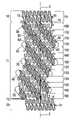
- FIG. 2is planar view of a flattened portion of the circumference of the stent in FIG. 1 .
- FIG. 3is an enlarged portion of FIG. 2 .
- FIG. 4is another planar view of a flattened portion of the circumference of a stent according to the present invention in its unexpanded state.
- FIG. 5is an enlarged view of a portion of FIG. 4 showing a first circumferential element of the stent.
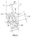
- FIG. 6is an enlarged view of a portion of FIG. 4 showing a second circumferential element of the stent.
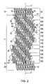
- FIG. 7is a planar view of a flattened portion of the stent in FIG. 1 showing a plurality of sets of helical segments propagating through the stent's body.
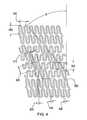
- FIG. 8is a planar view of a flattened endzone that may be employed in a stent of the present invention.
- FIG. 9is a planar view of a flattened portion of part of the endzone shown in FIG. 8 .
- FIG. 10is a planar view of a flattened portion of an expandable stent according to the present invention, after the stent has been deployed in a lumen.
- FIG. 11is three dimensional view of an alternative embodiment of the present invention.
- FIG. 12is a three dimensional view of an another stent according to the present invention.
- FIG. 13is a planar view of the stent shown in 12 .
- FIG. 14is a detailed view of a portion of FIG. 13 .
- FIG. 15is a detailed view of another portion of FIG. 13 .
- the present inventionis directed to an expandable stent, as well as a method of manufacturing the stent.
- the stentcomprises a generally cylindrical shaped main body section 11 having a cylindrical axis 5 and a wall thickness 103 .
- the wall thickness 103may optionally be uniform throughout the stent.
- the main body section 11is comprised of a plurality of helical segments 30 and 40 and a plurality of main body cylindrical elements 100 , each having cylindrical axes (not shown) that are collinear with the main body cylindrical axis 5 .
- the main body cylindrical elements 100are each comprised of circumferential elements 50 that are joined together by the helical segments 30 and 40 to form individual cylinders 100 .
- the stentmay also have a first endzone 10 and a second endzone 20 that straddle the body section 11 .
- the endzones 10 and 20may advantageously provide the stent with square outer edges 8 .
- the stentmay be manufactured from stainless steel, or other suitable materials. In most embodiments, it is desirable that the material, or a portion of the material, be radiopaque and that the various segments that form the stent be contiguous. Although, in some embodiments, the various segments that make up the stent can be distinct elements that are joined together.
- the main body 11may be formed in numerous ways.
- the body 11may contain two or more first helical segment 30 and 40 that are generally parallel to each other. In some embodiments they may be opposite each other by 180.°
- the first helical segments 30 and 40will be spaced equidistant along the circumference 110 of the main body 11 .
- the first helical segments 30 and 40are joined by a plurality of circumferential segments 50 to form a plurality of main body cylindrical elements 100 , which may be only generally cylindrically shaped.
- the circumferential segments 50make up a majority of the circumference 110 of each cylindrical element 100 .
- the helical segments 30 and 40connect each cylindrical element 100 to an adjacent cylindrical element 100 to form the main body 11 .
- the body of the stent 11may comprise a plurality of main body cylindrical elements 100 formed from first circumferential segments 50 that are joined with second circumferential segments 60 .
- the second circumferential segments 60 of each cylindrical element 100may be joined with second circumferential segments 60 of adjacent cylindrical elements 100 to form a plurality of first helical segments 30 and 40 in the main body 11 .
- Each first circumferential segment 50may have a circumferential dimension 55 and each second circumferential segments 60 may have a circumferential dimension 66 ′ (See FIG. 3 ).
- the first circumferential segment 50may be an expandable segment formed from plurality of segments joined together to form a pattern.
- the patternsuch as the one shown in the FIGS. 1-3 , may be a repeating pattern that resembles a square wave form having curved peaks and valleys. Other patterns, both repeating and non-repeating, may be used.
- the first circumferential segments 50may resemble a triangle wave form, a sinusoidal wave form, other repetitious patterns, or any pattern that enables the segment to expand when a radial force is exerted on the stent from the inside or collapse radially when an external crimping force is applied.
- the first circumferential elements 50may have a filament width 420 (see FIG. 4 ).
- the filament widthmay vary between 0.002 inches and 0.007 inches, but is preferably about 0.0050 inches. Other filament widths may be used depending on the parameters of the stent.
- the first circumferential elements 50comprise linear portions 320 and curved portions 328 that join the linear portions 320 together to form a repeating pattern.
- the linear portion 320may be parallel to the cylindrical axis of the stent. In other embodiments, the linear portion 320 lies at an angle of between 0-45 degrees with respect to the cylindrical axis.
- the first circumferential segment 50has an amplitude 350 and a period 380 . In one embodiment the amplitude may range from 0.5 mm to 2.0 mm and the period may range from 0.5 mm to 2.0 mm. In some embodiments, the amplitude is less than the period. Other amplitudes and periods may be used depending on the overall stent design and performance constraints.
- the second circumferential element 60which may be joined together in a helical pattern to form one or more helical segments 30 or 40 , may also take numerous forms, in addition to the form shown in FIG. 6 .
- the second circumferential element 60comprises linear portions 412 and curved portions 414 having a filament width 407 , and resembles generally an S-shaped structure.
- the second element circumferential segment 60may have an angled portion 417 attached to the linear portion 412 at an end opposite that of the curved portion 414 .
- the angled portionmay be oriented to form an angle ⁇ relative to the cylindrical axis of the stent 5 in the range of 0-45 degrees.
- the preferable angle ⁇is about 10 degrees.
- the linear portions 412 of the second circumferential element 60lies at an angle ⁇ relative to the cylindrical axis of the stent, wherein ⁇ preferably ranges from 0 to 45 degrees. When viewed in a planar fashion as in FIG. 2 , the linear portions 412 may, in some embodiments, form an angle ⁇ , relative to the cylindrical axis of the stent. In some embodiments, ⁇ may be approximately equal to the helical angle of the first helical segments 30 and 40 .
- the second circumferential elements 60may have an amplitude 300 (see FIGS.
- the preferred periodis about 0.82 mm and the preferred length of the linear portion 412 is about 0.5 mm and the amplitude 300 is about 0.38 mm.
- the amplitude of the second circumferential element 60may be greater than, equal to, or less than the amplitude of the first circumferential element 50 .
- the circumferential contributions of the first circumferential elements 50 to the overall circumference of the main body 11is greater than the circumferential contribution of the second circumferential element 60 , in terms of either circumferential length or circumferential cylindrical surface area.
- the stentmay have an overall outer surface area of about 0.029 square inches.
- the stentmay have a main body 11 comprised of two or more first helical segments 30 and 40 , as well as two or more second helical segments 200 and 210 .
- the first and second helical segments 30 , 40 and 200 , 210are joined together to form a generally cylindrically shaped body 11 .
- the first and second helical segmentsmay share a common connecting element 250 .
- the common connecting element 250may be H-shaped and the two generally parallel linear portions of the H-shaped connecting segment 250 may form an angle ⁇ relative to the axis 5 . (See FIG. 6 ).
- ⁇may, in one embodiment, be about 14 degrees. As is shown in FIG.
- the first helical segments 30 and 40 and second helical segments 200 and 210may have different pitches, i.e. number of spirals per unit length, which results in the first and second helical segments as having different helical angles ( ⁇ and ⁇ , respectively) i.e. the angle of the helical segment relative to the cylindrical axis 5 of the stent.
- the second helical segments 200 and 210have a pitch approximately twice that of the first helical segments.
- ⁇may vary from 0 to 45 degrees and is preferably about 40 degrees and ⁇ is preferably about twice ⁇ .
- the angle ⁇may range from 0 to 90 degrees.to the circumference 110 of each cylindrical element 100 .
- the helical segments 30 , 40are circumferentially expandable (i.e. they expand along the circumference of the stent) and may be formed from a plurality of circumferential elements 60 that in turn are made up of linear 412 and/or curved 414 segments (see FIG. 6 ) that each have a filament width 407 (see FIG. 6 ) that is less than the circumferential dimension 66 of the circumferential element 60 (see FIG. 3 ).
- each helical segment 30 or 40will make a total contribution to the circumference of each cylindrical element 100 that is greater than the filament width 407 .
- each helical segment 30 or 40may be greater than the circumferential contribution of the filament widths 407 of the segments (e.g. 412 and 414 ) making up the circumferential elements 60 that in turn make up the helical segments.
- the circumferential contribution of the helical segments 30 and 40 to the circumference 110 of each cylindrical element 100is more than just a function of the filament width 407 , e.g., it may be a function of the geometry of the element 60 .
- the geometry of the helical segments 30 and 40are a factor in determining their expandability.
- the helical segments 200 , 210are circumferentially expandable and may be comprised of other circumferential elements 50 that are in turn comprised of linear 320 and/or curved segments 328 (see FIGS. 3 and 5 ) that have a filament width 420 (see FIG. 4 ).
- the contribution of the helical segments 200 , 210 to the overall circumferential dimension 110 of each cylindrical element 100is greater than just the contribution of the filament widths 420 of the individual segments 320 and 328 that make up the elements 50 that in turn make up the helical segments 200 , 210 .
- the geometry of the elements 50 making up the helical segments 200 , 210may be a more important factor in determining the circumferential contribution of the helical segments 200 and 210 to the overall stent circumference than the filament width 420 .
- the circumference of the stent 110 in its unexpanded state and the circumference 105 when the stent is expandedare primarily functions of the geometry of the elements 50 and 60 that make up the helical segments 30 , 40 and 200 , 210 , respectively.
- Some, but not all embodiments, of the present inventionmay employ endzones 10 and 20 . (See FIGS. 1 , 2 , and 11 ).
- Stents that employ endzoneswill generally have two endzone regions straddling a central zone in the middle of the stent.
- the stentsmay also have a transition region between the endzone and the central zone.
- the transition regionserves to help smoothly transition between the expanded middle region and portions of the end of the stent that remain unexpanded after the stent is implanted.
- the size and characteristics of the transition regionare a function of the material and geometry of the stent.
- the transition range propertiesvary as a function of, among other things, the helical angle of the first helical segments, the number of curved segments located in the endzones, and the angle ⁇ of the linear portions of the segments forming the endzones. (See e.g. FIG. 8 ).
- the endzones 10 and 20may take numerous forms.
- the endzonesmay be comprised of one or more rings 17 .
- the rings 17may be generally cylindrically shaped, and in some embodiments, right cylindrically shaped.
- the ringsare formed from linear segments 28 joined together by curved segments 29 to form a pattern.
- the patternwhich is preferably—but not necessarily—a repeating pattern may take numerous forms, including the one shown.
- the endzones 10 and 20may be comprised of a plurality of rings 17 attached together.
- Struts 15may be used to attach the rings together to form the endzone and to attach the endzone to the main body 11 .
- the strutsin some embodiments, act as cantilever springs and there stiffness, which is a function of their width and thickness, may define bending properties of the stent along its cylindrical axis 5 .
- the linear segments 28 in the endzone 10are oriented at an angle ⁇ relative to the cylindrical axis of the stent.
- the angle ⁇is greater than 0 degrees.
- ⁇may range from 0 to 45 degrees and in still another embodiment is preferably about 10 degrees.
- the segments of the endzonemay have a filament width 13 of between 0.002 and 0.007 inches.
- the repeating pattern of the endzonehas a period 2 of about 0.027 inches and an amplitude 21 of about 0.043 inches. Other values may be used. As is shown in FIG.
- the struts 15which are but one way to attach the endzones 10 and 20 to the main body 11 , may, in one embodiment have a width of between 0.002 inches and 0.08 inches and preferably the width does not exceed the wall thickness, which typically—but not necessarily ranges from about 0.002 to 0.008 inches.
- the stent of the present inventionmay, after insertion into a vessel, be expanded such that it plastically deforms from the unexpanded state to an expanded state having a diameter increase of about 400 to 500%, which results in a larger circumference 105 .
- FIG. 11depicts the stent shown in FIG. 1 in an expanded state.
- the stent's outer diameterin one particular embodiment increases from 1.0 mm to 3.00 mm and maintains a stent-to-vessel ratio in the expanded state that is greater than on average 16%.
- FIGS. 12-15depict an endzoneless stent. Like the stent shown in FIGS. 19 , the stent of FIGS. 12-15 comprises a plurality of adjacent cylindrical elements 100 .
- the cylindrical elements 100are formed from a plurality of first circumferential elements 50 ′ and second circumferential elements 60 .
- the first circumferential elements 50 ′ of the stent in FIGS. 12-15are substantially identical to the second circumferential element 60 except that they are rotated to have a different orientation.
- the circumferential elementsmay be generally S-shaped having a linear portion 412 , a curved portion 414 having a radius R, and an angled portion 417 .
- Rmay vary widely depending on overall stent characteristics and in one embodiment varies between 0.001 and 0.02 inches and is preferably about 0.0083 inches.
- the angled portion 417is spaced a distance 499 from the linear portion. In one particular embodiment, the distance 499 may vary from 0.002 to 0.020 inches and is preferably about 0.007 inches.
- the filament width 407 of the elementsmay, in one embodiment, be about 0.13 mm.
- angle Kmay be generally S-shaped having a linear portion 412 , a curved portion 414 having a radius R, and an angled portion 417 .
- the angle Kmay vary widely depending on overall stent characteristics and range of radial compression or expansion about the axis 5 .
- Adjacent cylindrical elements 100are joined together by connecting first circumferential elements 50 ′ in each cylindrical element 100 with first circumferential elements 50 ′ in an adjacent cylindrical element 100 , such that the first circumferential elements 50 ′ in adjacent cylindrical elements 100 form helixes through the stent and such that second circumferential elements form helixes through the stent having an angle ⁇ relative to the axis 5 .
- a connecting segment 250(see FIG. 7 ) is used to connect first circumferential elements in adjacent cylindrical elements 100 and to connect second circumferential elements 60 in adjacent cylindrical elements 100 .
- the connecting segmentconnects first circumferential elements 50 ′ in each cylindrical element 100 with two second circumferential elements 60 in each cylindrical element 100 .
- the individual cylindrical elements 100are adjacent to each other and are located a distance 666 apart. In one embodiment, the preferred may range between 0.002 and 0.020 inches, and is preferably about 0.009 inches.
- the above description of the stent of the present inventionis illustrative and not exhaustive. Various modifications may be made to the stent to change its overall characteristics without deviating from the scope and spirit of the invention as defined by the claims.
- the increasing the length of the linear segments and or increasing the arc of the second circumferential elements 60will decrease the amount of radial force required to expand each circular section and will increase flexibility.
- Increasing the angle ⁇ of the second circumferential element 60will: (i) increase the amount of radial force required for expansion, (ii) increase surface area, and (iii) decrease flexibility.
- various modificationsmay be made to the struts 15 . (See FIG. 2 ).
- Increasing strut width and wall thicknesswill: (i) increase surface area, (ii) increase radial strength, (iii) increase pressure required to expand the stent radially, (iv) decrease flexibility, and, in the case of increased wall thickness, (v) increase radiopacity.
- the stent of the present inventionmay be manufactured in numerous ways.
- the stentmay be formed from a metallic tube by removing various portions of the tube's wall to form the patterns described herein.
- the resulting stentwill thus be formed from a single contiguous piece of material, eliminating the need for connecting various segments together.
- Material from the tube wallmay be removed using various techniques including laser (YAG laser for example), electrical discharge, chemical etching, metal cutting, a combination of these techniques, or other well known techniques. See e.g. U.S. Pat. Nos. 5,879,381 to Moriuchi et al. and 6,117,165 to Becker, which are hereby incorporated in their entirety by reference.
- the tube from which the stent is formedmay have an internal diameter of about 3.0 mm, a wall thickness of about 1.0 mm and a length of about 30 mm. Tubes having other dimensions may be used. In particular, the length may be adapted to that of the diseased part of the lumen in which the stent is to be placed. This may avoid using separate stents to cover the total diseased area.
Landscapes
- Health & Medical Sciences (AREA)
- Engineering & Computer Science (AREA)
- Biomedical Technology (AREA)
- Heart & Thoracic Surgery (AREA)
- Life Sciences & Earth Sciences (AREA)
- Cardiology (AREA)
- Oral & Maxillofacial Surgery (AREA)
- Transplantation (AREA)
- Physics & Mathematics (AREA)
- Vascular Medicine (AREA)
- Optics & Photonics (AREA)
- Animal Behavior & Ethology (AREA)
- General Health & Medical Sciences (AREA)
- Public Health (AREA)
- Veterinary Medicine (AREA)
- Media Introduction/Drainage Providing Device (AREA)
- Prostheses (AREA)
Abstract
Description
Claims (34)
Priority Applications (16)
| Application Number | Priority Date | Filing Date | Title |
|---|---|---|---|
| US10/014,705US7329277B2 (en) | 1997-06-13 | 2001-12-11 | Stent having helical elements |
| US12/027,382US8486133B2 (en) | 1997-06-13 | 2008-02-07 | Stent having helical elements |
| US12/178,396US20080288051A1 (en) | 1997-06-13 | 2008-07-23 | Stent having helical elements |
| US12/178,387US20080288050A1 (en) | 1997-06-13 | 2008-07-23 | Stent having helical elements |
| US12/178,915US8382820B2 (en) | 1997-06-13 | 2008-07-24 | Stent having helical elements |
| US12/178,895US20080294243A1 (en) | 1997-06-13 | 2008-07-24 | Stent having helical elements |
| US12/178,889US20080281407A1 (en) | 1997-06-13 | 2008-07-24 | Stent having helical elements |
| US12/178,906US8968385B2 (en) | 1997-06-13 | 2008-07-24 | Stent having helical elements |
| US12/178,909US20080288052A1 (en) | 1997-06-13 | 2008-07-24 | Stent having helical elements |
| US12/178,883US20080281406A1 (en) | 1997-06-13 | 2008-07-24 | Stent having helical elements |
| US12/178,898US20080294244A1 (en) | 1997-06-13 | 2008-07-24 | Stent having helical elements |
| US12/196,761US20080319537A1 (en) | 1997-06-13 | 2008-08-22 | Stent having helical elements |
| US12/243,392US7682384B2 (en) | 1997-06-13 | 2008-10-01 | Stent with helical elements |
| US12/727,567US8372135B2 (en) | 1997-06-13 | 2010-03-19 | Stent having helical elements |
| US12/878,341US7942922B2 (en) | 1997-06-13 | 2010-09-09 | Stent having helical elements |
| US12/878,232US7967852B2 (en) | 1997-06-13 | 2010-09-09 | Stent having helical elements |
Applications Claiming Priority (8)
| Application Number | Priority Date | Filing Date | Title |
|---|---|---|---|
| EP97201799AEP0890346A1 (en) | 1997-06-13 | 1997-06-13 | Expandable intraluminal endoprosthesis |
| EP97201799.0 | 1997-06-13 | ||
| EP98201446AEP0884029B1 (en) | 1997-06-13 | 1998-05-06 | Expandable intraluminal endoprosthesis |
| EP98201446.6 | 1998-05-06 | ||
| US09/094,402US6117165A (en) | 1997-06-13 | 1998-06-10 | Expandable intraluminal endoprosthesis |
| US09/511,481US7108714B1 (en) | 1997-06-13 | 2000-02-23 | Expandable intraluminal endoprosthesis |
| US25468800P | 2000-12-11 | 2000-12-11 | |
| US10/014,705US7329277B2 (en) | 1997-06-13 | 2001-12-11 | Stent having helical elements |
Related Parent Applications (3)
| Application Number | Title | Priority Date | Filing Date |
|---|---|---|---|
| US09/094,402Continuation-In-PartUS6117165A (en) | 1997-06-13 | 1998-06-10 | Expandable intraluminal endoprosthesis |
| US09/511,481Continuation-In-PartUS7108714B1 (en) | 1997-06-13 | 2000-02-23 | Expandable intraluminal endoprosthesis |
| US25468800PContinuation-In-Part | 1997-06-13 | 2000-12-11 |
Related Child Applications (1)
| Application Number | Title | Priority Date | Filing Date |
|---|---|---|---|
| US12/027,382ContinuationUS8486133B2 (en) | 1997-06-13 | 2008-02-07 | Stent having helical elements |
Publications (2)
| Publication Number | Publication Date |
|---|---|
| US20020095206A1 US20020095206A1 (en) | 2002-07-18 |
| US7329277B2true US7329277B2 (en) | 2008-02-12 |
Family
ID=46278568
Family Applications (1)
| Application Number | Title | Priority Date | Filing Date |
|---|---|---|---|
| US10/014,705Expired - Fee RelatedUS7329277B2 (en) | 1997-06-13 | 2001-12-11 | Stent having helical elements |
Country Status (1)
| Country | Link |
|---|---|
| US (1) | US7329277B2 (en) |
Cited By (65)
| Publication number | Priority date | Publication date | Assignee | Title |
|---|---|---|---|---|
| US20040193250A1 (en)* | 1998-09-05 | 2004-09-30 | Jomed Gmbh | Methods and apparatus for a stent having an expandable web structure |
| US20040236407A1 (en)* | 1998-09-05 | 2004-11-25 | Abbott Laboratories Vascular Enterprises Limited | Methods and apparatus for stenting comprising enhanced embolic protection coupled with improved protections against restenosis and thrombus formation |
| US20060122691A1 (en)* | 1998-12-03 | 2006-06-08 | Jacob Richter | Hybrid stent |
| US20060136041A1 (en)* | 2004-12-17 | 2006-06-22 | Schmid Eric V | Slide-and-lock stent |
| US20060178727A1 (en)* | 1998-12-03 | 2006-08-10 | Jacob Richter | Hybrid amorphous metal alloy stent |
| US20060184232A1 (en)* | 1998-09-05 | 2006-08-17 | Abbott Laboratories Vascular | Methods and apparatus for curved stent |
| US20070032857A1 (en)* | 2005-08-02 | 2007-02-08 | Schmid Eric V | Axially nested slide and lock expandable device |
| US20070142901A1 (en)* | 1998-02-17 | 2007-06-21 | Steinke Thomas A | Expandable stent with sliding and locking radial elements |
| US20070219642A1 (en)* | 1998-12-03 | 2007-09-20 | Jacob Richter | Hybrid stent having a fiber or wire backbone |
| US20070233235A1 (en)* | 2002-10-09 | 2007-10-04 | Boston Scientific Scimed, Inc. | Stent with Improved Flexibility |
| US20080103589A1 (en)* | 2002-12-30 | 2008-05-01 | Advanced Cardiovascular Systems, Inc. | Flexible stent |
| US20080281406A1 (en)* | 1997-06-13 | 2008-11-13 | Orbusneich Medical, Inc. | Stent having helical elements |
| US20080294240A1 (en)* | 2007-05-23 | 2008-11-27 | Abbott Laboratories Vascular Enterprises Limited | Flexible stent with torque-absorbing connectors |
| US20090030501A1 (en)* | 2005-08-02 | 2009-01-29 | Reva Medical, Inc. | Axially nested slide and lock expandable device |
| US20090143853A1 (en)* | 2007-11-30 | 2009-06-04 | Andrew Morris | Axially-radially nested expandable device |
| US20090163996A1 (en)* | 2007-12-20 | 2009-06-25 | Abbott Laboratories Vascular Enterprises Limited | Endoprosthesis having a stable architecture |
| US20090163992A1 (en)* | 2007-12-20 | 2009-06-25 | Abbott Laboratories Vascular Enterprises Limited | Endoprosthesis having flexible connectors |
| US20090234433A1 (en)* | 1998-12-03 | 2009-09-17 | Medinol Ltd. | Helical hybrid stent |
| US20100114297A1 (en)* | 2001-09-18 | 2010-05-06 | Abbott Laboratories Vascular Enterprises Limited | Stent |
| US20100211159A1 (en)* | 2007-01-26 | 2010-08-19 | Reva Medical, Inc. | Circumferentially nested expandable device |
| US20100217380A1 (en)* | 2009-02-02 | 2010-08-26 | Ryan Donovan | Flexible stent design |
| US7815763B2 (en) | 2001-09-28 | 2010-10-19 | Abbott Laboratories Vascular Enterprises Limited | Porous membranes for medical implants and methods of manufacture |
| US20100274350A1 (en)* | 2009-04-22 | 2010-10-28 | Medinol Ltd. | Helical hybrid stent |
| US20100292773A1 (en)* | 2004-07-21 | 2010-11-18 | Reva Medical, Inc. | Balloon expandable crush-recoverable stent device |
| US7850726B2 (en) | 2007-12-20 | 2010-12-14 | Abbott Laboratories Vascular Enterprises Limited | Endoprosthesis having struts linked by foot extensions |
| US20100328087A1 (en)* | 2009-06-28 | 2010-12-30 | Oki Data Corporation | Communication apparatus, connection control method for communication apparatus and method of determining state of communication plug relative to communication connector in communication apparatus |
| US7887578B2 (en) | 1998-09-05 | 2011-02-15 | Abbott Laboratories Vascular Enterprises Limited | Stent having an expandable web structure |
| US20110071615A1 (en)* | 2009-09-18 | 2011-03-24 | Medtronic Vascular, Inc. | Methods for Forming an Orthogonal End on a Helical Stent |
| US7947071B2 (en) | 2008-10-10 | 2011-05-24 | Reva Medical, Inc. | Expandable slide and lock stent |
| US20110125251A1 (en)* | 2009-05-14 | 2011-05-26 | Orbusneich Medical, Inc. | Self-Expanding Stent with Polygon Transition Zone |
| US20110130822A1 (en)* | 2007-07-20 | 2011-06-02 | Orbusneich Medical, Inc. | Bioabsorbable Polymeric Compositions and Medical Devices |
| US20110137335A1 (en)* | 2007-09-07 | 2011-06-09 | Crusader Medical Llc | Percutaneous Retrievable Vascular Filter |
| US20110202076A1 (en)* | 2003-06-27 | 2011-08-18 | Zuli Holdings, Ltd. | Amorphous metal alloy medical devices |
| US20110218615A1 (en)* | 2010-03-02 | 2011-09-08 | Medtronic Vascular, Inc. | Stent With Multi-Crown Constraint and Method for Ending Helical Wound Stents |
| US8016874B2 (en) | 2007-05-23 | 2011-09-13 | Abbott Laboratories Vascular Enterprises Limited | Flexible stent with elevated scaffolding properties |
| US8088060B2 (en) | 2000-03-15 | 2012-01-03 | Orbusneich Medical, Inc. | Progenitor endothelial cell capturing with a drug eluting implantable medical device |
| US20120029622A1 (en)* | 2010-08-02 | 2012-02-02 | Baillargeon Brian P | Flexible helical stent having different helical regions |
| US8206434B2 (en) | 2010-03-02 | 2012-06-26 | Medtronic Vascular, Inc. | Stent with sinusoidal wave form and orthogonal end and method for making same |
| US8328072B2 (en) | 2010-07-19 | 2012-12-11 | Medtronic Vascular, Inc. | Method for forming a wave form used to make wound stents |
| US8449597B2 (en) | 1995-03-01 | 2013-05-28 | Boston Scientific Scimed, Inc. | Longitudinally flexible expandable stent |
| US20130204350A1 (en)* | 2003-06-27 | 2013-08-08 | Medinol Ltd. | Helical hybrid stent |
| US8512395B2 (en) | 2010-12-30 | 2013-08-20 | Boston Scientific Scimed, Inc. | Stent with horseshoe shaped bridges |
| US8523936B2 (en) | 2010-04-10 | 2013-09-03 | Reva Medical, Inc. | Expandable slide and lock stent |
| US8663313B2 (en) | 2011-03-03 | 2014-03-04 | Boston Scientific Scimed, Inc. | Low strain high strength stent |
| US8790388B2 (en) | 2011-03-03 | 2014-07-29 | Boston Scientific Scimed, Inc. | Stent with reduced profile |
| US8920489B2 (en) | 2010-08-02 | 2014-12-30 | Cordis Corporation | Flexible stent having protruding hinges |
| USD723165S1 (en) | 2013-03-12 | 2015-02-24 | C. R. Bard, Inc. | Stent |
| US9066825B2 (en) | 2012-05-14 | 2015-06-30 | C.R. Bard, Inc. | Uniformly expandable stent |
| US9155644B2 (en) | 2010-08-02 | 2015-10-13 | Cordis Corporation | Flexible helical stent having intermediate structural feature |
| US9180031B2 (en) | 2013-03-15 | 2015-11-10 | Covidien Lp | Stent with varying radius between struts |
| US9238260B2 (en) | 2012-04-18 | 2016-01-19 | Medtronic Vascular, Inc. | Method and apparatus for creating formed elements used to make wound stents |
| US9242290B2 (en) | 2012-04-03 | 2016-01-26 | Medtronic Vascular, Inc. | Method and apparatus for creating formed elements used to make wound stents |
| US9259335B2 (en) | 2013-03-15 | 2016-02-16 | Covidien Lp | Stent |
| US9296034B2 (en) | 2011-07-26 | 2016-03-29 | Medtronic Vascular, Inc. | Apparatus and method for forming a wave form for a stent from a wire |
| US9364351B2 (en) | 2012-04-23 | 2016-06-14 | Medtronic Vascular, Inc. | Method for forming a stent |
| US9408732B2 (en) | 2013-03-14 | 2016-08-09 | Reva Medical, Inc. | Reduced-profile slide and lock stent |
| US9452039B2 (en) | 2012-02-23 | 2016-09-27 | Merit Medical Systems, Inc. | Vascular filter |
| US9522217B2 (en) | 2000-03-15 | 2016-12-20 | Orbusneich Medical, Inc. | Medical device with coating for capturing genetically-altered cells and methods for using same |
| US10231855B2 (en) | 2010-08-02 | 2019-03-19 | CARDINAL HEALTH SWITZERLAND 515 GmbH | Flexible helical stent having intermediate non-helical region |
| US10258488B2 (en) | 2016-11-14 | 2019-04-16 | Covidien Lp | Stent |
| US10449069B2 (en) | 2016-11-14 | 2019-10-22 | Covidien Lp | Stent |
| US10722338B2 (en) | 2013-08-09 | 2020-07-28 | Merit Medical Systems, Inc. | Vascular filter delivery systems and methods |
| US10905572B2 (en) | 2016-11-14 | 2021-02-02 | Covidien Lp | Stent |
| US11986408B2 (en) | 2020-07-24 | 2024-05-21 | Medtronic Vascular, Inc. | Stent with mid-crowns |
| US11998464B2 (en) | 2020-07-24 | 2024-06-04 | Medtronic Vascular, Inc. | Stent with angled struts and crowns |
Families Citing this family (50)
| Publication number | Priority date | Publication date | Assignee | Title |
|---|---|---|---|---|
| US5755682A (en)* | 1996-08-13 | 1998-05-26 | Heartstent Corporation | Method and apparatus for performing coronary artery bypass surgery |
| US6290728B1 (en) | 1998-09-10 | 2001-09-18 | Percardia, Inc. | Designs for left ventricular conduit |
| AU6384699A (en)* | 1998-09-10 | 2000-04-03 | Percardia, Inc. | Tmr shunt |
| US6641610B2 (en) | 1998-09-10 | 2003-11-04 | Percardia, Inc. | Valve designs for left ventricular conduits |
| US6254564B1 (en) | 1998-09-10 | 2001-07-03 | Percardia, Inc. | Left ventricular conduit with blood vessel graft |
| JP2002524196A (en)* | 1998-09-10 | 2002-08-06 | パーカーディア,インコーポレイティド | Transmyocardial shunt for left ventricular revascularization and its mounting mechanism |
| US7983734B2 (en)* | 2003-05-23 | 2011-07-19 | Senorx, Inc. | Fibrous marker and intracorporeal delivery thereof |
| US6409697B2 (en) | 1999-05-04 | 2002-06-25 | Heartstent Corporation | Transmyocardial implant with forward flow bias |
| US6638237B1 (en) | 1999-08-04 | 2003-10-28 | Percardia, Inc. | Left ventricular conduits and methods for delivery |
| US7033372B1 (en) | 1999-08-04 | 2006-04-25 | Percardia, Inc. | Corkscrew reinforced left ventricle to coronary artery channel |
| US20020032478A1 (en)* | 2000-08-07 | 2002-03-14 | Percardia, Inc. | Myocardial stents and related methods of providing direct blood flow from a heart chamber to a coronary vessel |
| US6976990B2 (en) | 2001-01-25 | 2005-12-20 | Percardia, Inc. | Intravascular ventriculocoronary bypass via a septal passageway |
| US6949118B2 (en) | 2002-01-16 | 2005-09-27 | Percardia, Inc. | Encased implant and methods |
| US7008397B2 (en) | 2002-02-13 | 2006-03-07 | Percardia, Inc. | Cardiac implant and methods |
| US7326219B2 (en) | 2002-09-09 | 2008-02-05 | Wilk Patent Development | Device for placing transmyocardial implant |
| US20040054398A1 (en)* | 2002-09-13 | 2004-03-18 | Cully Edward H. | Stent device with multiple helix construction |
| DE10243136A1 (en)* | 2002-09-17 | 2004-05-19 | Campus Medizin & Technik Gmbh | Stent for implantation in or around a hollow organ |
| FR2846520B1 (en)* | 2002-11-06 | 2006-09-29 | Roquette Freres | USE OF MALTODEXTRINS BRANCHED AS BLEACHES OF GRANULATION |
| DE10261822A1 (en)* | 2002-12-20 | 2004-07-01 | Biotronik Meß- und Therapiegeräte GmbH & Co. Ingenieurbüro Berlin | Helix bridge connection |
| US20050033410A1 (en)* | 2002-12-24 | 2005-02-10 | Novostent Corporation | Vascular prothesis having flexible configuration |
| US20050165469A1 (en)* | 2002-12-24 | 2005-07-28 | Michael Hogendijk | Vascular prosthesis including torsional stabilizer and methods of use |
| US7846198B2 (en)* | 2002-12-24 | 2010-12-07 | Novostent Corporation | Vascular prosthesis and methods of use |
| US20040158314A1 (en)* | 2002-12-24 | 2004-08-12 | Novostent Corporation | Ribbon-type vascular prosthesis having stress-relieving articulation and methods of use |
| US20040160685A1 (en)* | 2003-01-27 | 2004-08-19 | Everardo Daniel Faires Quiros | Lower rear view mirror (LRVM for short) |
| DE102005003632A1 (en) | 2005-01-20 | 2006-08-17 | Fraunhofer-Gesellschaft zur Förderung der angewandten Forschung e.V. | Catheter for the transvascular implantation of heart valve prostheses |
| ATE416736T1 (en)* | 2005-08-10 | 2008-12-15 | Axetis Ag | TUBULAR SUPPORT PROSTHESIS WITH LATERALLY OVERLAPING CURVES |
| US20070142903A1 (en)* | 2005-12-15 | 2007-06-21 | Dave Vipul B | Laser cut intraluminal medical devices |
| USD597671S1 (en) | 2006-10-20 | 2009-08-04 | Orbusneich Medical, Inc. | Polymeric stent structure |
| USD568476S1 (en) | 2006-10-27 | 2008-05-06 | Orbusneich Medical, Inc. | Interlocking tubular stent structure |
| US8460364B2 (en)* | 2006-07-20 | 2013-06-11 | Orbusneich Medical, Inc. | Bioabsorbable polymeric medical device |
| EP2056742A4 (en)* | 2006-07-24 | 2010-03-31 | Existent Inc | Stent designs, materials and processing methods |
| US7896915B2 (en) | 2007-04-13 | 2011-03-01 | Jenavalve Technology, Inc. | Medical device for treating a heart valve insufficiency |
| US9044318B2 (en) | 2008-02-26 | 2015-06-02 | Jenavalve Technology Gmbh | Stent for the positioning and anchoring of a valvular prosthesis |
| BR112012021347A2 (en) | 2008-02-26 | 2019-09-24 | Jenavalve Tecnology Inc | stent for positioning and anchoring a valve prosthesis at an implantation site in a patient's heart |
| US9149377B2 (en)* | 2008-10-10 | 2015-10-06 | Veryan Medical Ltd. | Stent suitable for deployment in a blood vessel |
| US20110295358A1 (en)* | 2008-12-29 | 2011-12-01 | Silvio Rudolph Schaffner | Endoluminal prosthesis |
| EP2338537A2 (en)* | 2009-12-21 | 2011-06-29 | Biotronik VI Patent AG | Aptamer coated implant, process of production and uses |
| US10856978B2 (en) | 2010-05-20 | 2020-12-08 | Jenavalve Technology, Inc. | Catheter system |
| WO2011147849A1 (en) | 2010-05-25 | 2011-12-01 | Jenavalve Technology Inc. | Prosthetic heart valve and transcatheter delivered endoprosthesis comprising a prosthetic heart valve and a stent |
| USD665079S1 (en)* | 2010-07-16 | 2012-08-07 | Biocore Biotechnologia S/A | Coronary prosthesis |
| USD665080S1 (en)* | 2010-07-16 | 2012-08-07 | Biocore Biotechnologia S/A | Coronary prosthesis |
| USD665500S1 (en)* | 2011-04-15 | 2012-08-14 | Novostent Corporation | Stent |
| CN105491978A (en) | 2013-08-30 | 2016-04-13 | 耶拿阀门科技股份有限公司 | Radially collapsible frame for a prosthetic valve and method for manufacturing such a frame |
| EP3270825B1 (en) | 2015-03-20 | 2020-04-22 | JenaValve Technology, Inc. | Heart valve prosthesis delivery system |
| US10709555B2 (en) | 2015-05-01 | 2020-07-14 | Jenavalve Technology, Inc. | Device and method with reduced pacemaker rate in heart valve replacement |
| US20200179144A1 (en)* | 2016-03-31 | 2020-06-11 | CARDINAL HEALTH SWITZERLAND 515 GmbH | Helical ultra low foreshortening stent |
| WO2017195125A1 (en) | 2016-05-13 | 2017-11-16 | Jenavalve Technology, Inc. | Heart valve prosthesis delivery system and method for delivery of heart valve prosthesis with introducer sheath and loading system |
| WO2018138658A1 (en) | 2017-01-27 | 2018-08-02 | Jenavalve Technology, Inc. | Heart valve mimicry |
| US20210378849A1 (en)* | 2020-02-19 | 2021-12-09 | Medinol Ltd. | Stent with Enhanced Low Crimping Profile |
| WO2024102411A1 (en) | 2022-11-09 | 2024-05-16 | Jenavalve Technology, Inc. | Catheter system for sequential deployment of an expandable implant |
Citations (19)
| Publication number | Priority date | Publication date | Assignee | Title |
|---|---|---|---|---|
| US5449373A (en) | 1994-03-17 | 1995-09-12 | Medinol Ltd. | Articulated stent |
| US5697971A (en)* | 1996-06-11 | 1997-12-16 | Fischell; Robert E. | Multi-cell stent with cells having differing characteristics |
| US5733303A (en) | 1994-03-17 | 1998-03-31 | Medinol Ltd. | Flexible expandable stent |
| US5843120A (en) | 1994-03-17 | 1998-12-01 | Medinol Ltd. | Flexible-expandable stent |
| EP0884029A1 (en) | 1997-06-13 | 1998-12-16 | Gary J. Becker | Expandable intraluminal endoprosthesis |
| US5895406A (en) | 1996-01-26 | 1999-04-20 | Cordis Corporation | Axially flexible stent |
| US5913897A (en)* | 1993-09-16 | 1999-06-22 | Cordis Corporation | Endoprosthesis having multiple bridging junctions and procedure |
| EP0968689A2 (en) | 1998-07-03 | 2000-01-05 | W.C. Heraeus GmbH & Co. KG | Radially expandable support device (stent) IV |
| US6254632B1 (en)* | 2000-09-28 | 2001-07-03 | Advanced Cardiovascular Systems, Inc. | Implantable medical device having protruding surface structures for drug delivery and cover attachment |
| US6270524B1 (en)* | 1996-11-12 | 2001-08-07 | Medtronic, Inc. | Flexible, radially expansible luminal prostheses |
| US6331188B1 (en)* | 1994-08-31 | 2001-12-18 | Gore Enterprise Holdings, Inc. | Exterior supported self-expanding stent-graft |
| US20020095208A1 (en) | 2000-09-22 | 2002-07-18 | Scimed Life Systems, Inc. | Stent |
| US6432132B1 (en)* | 1999-01-12 | 2002-08-13 | Orbus Medical Technologies Inc. | Expandable intraluminal endoprosthesis |
| US20020116044A1 (en)* | 2000-05-22 | 2002-08-22 | Cottone, Robert John | Self-expanding stent |
| US6443982B1 (en) | 1994-03-17 | 2002-09-03 | Medinol, Ltd. | Flexible expandable stent |
| US6464722B2 (en) | 1994-03-17 | 2002-10-15 | Medinol, Ltd. | Flexible expandable stent |
| US6579314B1 (en)* | 1995-03-10 | 2003-06-17 | C.R. Bard, Inc. | Covered stent with encapsulated ends |
| US6682554B2 (en) | 1998-09-05 | 2004-01-27 | Jomed Gmbh | Methods and apparatus for a stent having an expandable web structure |
| US6974475B1 (en) | 1987-12-08 | 2005-12-13 | Wall W Henry | Angioplasty stent |
- 2001
- 2001-12-11USUS10/014,705patent/US7329277B2/ennot_activeExpired - Fee Related
Patent Citations (27)
| Publication number | Priority date | Publication date | Assignee | Title |
|---|---|---|---|---|
| US6974475B1 (en) | 1987-12-08 | 2005-12-13 | Wall W Henry | Angioplasty stent |
| US5913897A (en)* | 1993-09-16 | 1999-06-22 | Cordis Corporation | Endoprosthesis having multiple bridging junctions and procedure |
| US6461381B2 (en) | 1994-03-17 | 2002-10-08 | Medinol, Ltd. | Flexible expandable stent |
| US6508834B1 (en) | 1994-03-17 | 2003-01-21 | Medinol Ltd. | Articulated stent |
| US6875228B2 (en) | 1994-03-17 | 2005-04-05 | Medinol, Ltd. | Articulated stent |
| US6589276B2 (en) | 1994-03-17 | 2003-07-08 | Medinol Ltd. | Articulated stent |
| US5733303A (en) | 1994-03-17 | 1998-03-31 | Medinol Ltd. | Flexible expandable stent |
| US5972018A (en) | 1994-03-17 | 1999-10-26 | Medinol Ltd. | Flexible expandable stent |
| US5980552A (en) | 1994-03-17 | 1999-11-09 | Medinol Ltd. | Articulated stent |
| US6443982B1 (en) | 1994-03-17 | 2002-09-03 | Medinol, Ltd. | Flexible expandable stent |
| US6059811A (en) | 1994-03-17 | 2000-05-09 | Medinol Ltd. | Articulated stent |
| US6464722B2 (en) | 1994-03-17 | 2002-10-15 | Medinol, Ltd. | Flexible expandable stent |
| US5449373A (en) | 1994-03-17 | 1995-09-12 | Medinol Ltd. | Articulated stent |
| US6635084B2 (en) | 1994-03-17 | 2003-10-21 | Medinol, Ltd. | Flexible expandable stent |
| US5843120A (en) | 1994-03-17 | 1998-12-01 | Medinol Ltd. | Flexible-expandable stent |
| US6331188B1 (en)* | 1994-08-31 | 2001-12-18 | Gore Enterprise Holdings, Inc. | Exterior supported self-expanding stent-graft |
| US6579314B1 (en)* | 1995-03-10 | 2003-06-17 | C.R. Bard, Inc. | Covered stent with encapsulated ends |
| US5895406A (en) | 1996-01-26 | 1999-04-20 | Cordis Corporation | Axially flexible stent |
| US5697971A (en)* | 1996-06-11 | 1997-12-16 | Fischell; Robert E. | Multi-cell stent with cells having differing characteristics |
| US6270524B1 (en)* | 1996-11-12 | 2001-08-07 | Medtronic, Inc. | Flexible, radially expansible luminal prostheses |
| EP0884029A1 (en) | 1997-06-13 | 1998-12-16 | Gary J. Becker | Expandable intraluminal endoprosthesis |
| EP0968689A2 (en) | 1998-07-03 | 2000-01-05 | W.C. Heraeus GmbH & Co. KG | Radially expandable support device (stent) IV |
| US6682554B2 (en) | 1998-09-05 | 2004-01-27 | Jomed Gmbh | Methods and apparatus for a stent having an expandable web structure |
| US6432132B1 (en)* | 1999-01-12 | 2002-08-13 | Orbus Medical Technologies Inc. | Expandable intraluminal endoprosthesis |
| US20020116044A1 (en)* | 2000-05-22 | 2002-08-22 | Cottone, Robert John | Self-expanding stent |
| US20020095208A1 (en) | 2000-09-22 | 2002-07-18 | Scimed Life Systems, Inc. | Stent |
| US6254632B1 (en)* | 2000-09-28 | 2001-07-03 | Advanced Cardiovascular Systems, Inc. | Implantable medical device having protruding surface structures for drug delivery and cover attachment |
Cited By (159)
| Publication number | Priority date | Publication date | Assignee | Title |
|---|---|---|---|---|
| US8449597B2 (en) | 1995-03-01 | 2013-05-28 | Boston Scientific Scimed, Inc. | Longitudinally flexible expandable stent |
| US8728147B2 (en) | 1995-03-01 | 2014-05-20 | Boston Scientific Limited | Longitudinally flexible expandable stent |
| US8968385B2 (en)* | 1997-06-13 | 2015-03-03 | Orbusneich Medical, Inc. | Stent having helical elements |
| US8382820B2 (en)* | 1997-06-13 | 2013-02-26 | Orbusneich Medical, Inc. | Stent having helical elements |
| US8486133B2 (en) | 1997-06-13 | 2013-07-16 | Orbusneich Medical, Inc. | Stent having helical elements |
| US8372135B2 (en) | 1997-06-13 | 2013-02-12 | Orbusneich Medical, Inc. | Stent having helical elements |
| US20090024207A1 (en)* | 1997-06-13 | 2009-01-22 | Addonizio Scott J | Stent Having Helical Elements |
| US20080294244A1 (en)* | 1997-06-13 | 2008-11-27 | Orbusneich Medical, Inc. | Stent having helical elements |
| US20080294243A1 (en)* | 1997-06-13 | 2008-11-27 | Orbusneich Medical, Inc. | Stent having helical elements |
| US20080294241A1 (en)* | 1997-06-13 | 2008-11-27 | Orbusneich Medical, Inc. | Stent having helical elements |
| US20080288053A1 (en)* | 1997-06-13 | 2008-11-20 | Orbusneich Medical, Inc. | Stent having helical elements |
| US20080281406A1 (en)* | 1997-06-13 | 2008-11-13 | Orbusneich Medical, Inc. | Stent having helical elements |
| US20070142901A1 (en)* | 1998-02-17 | 2007-06-21 | Steinke Thomas A | Expandable stent with sliding and locking radial elements |
| US7927364B2 (en) | 1998-09-05 | 2011-04-19 | Abbott Laboratories Vascular Enterprises Limited | Methods and apparatus for stenting comprising enhanced embolic protection coupled with improved protections against restenosis and thrombus formation |
| US7789905B2 (en) | 1998-09-05 | 2010-09-07 | Abbottt Laboratories Vascular Enterprises Limited | Apparatus for a stent having an expandable web structure |
| US20060184232A1 (en)* | 1998-09-05 | 2006-08-17 | Abbott Laboratories Vascular | Methods and apparatus for curved stent |
| US20070179601A1 (en)* | 1998-09-05 | 2007-08-02 | Abbott Laboratories Vascular Enterprises Limited | Methods and apparatus for stenting comprising enhanced embolic protections coupled with improved protections against restenosis and trombus formation |
| US20070213800A1 (en)* | 1998-09-05 | 2007-09-13 | Abbott Laboratories Vascular Enterprises Limited | Method and apparatus for stenting comprising enhanced embolic protection coupled with improved protections against restenosis and thrombus formation |
| US8814926B2 (en) | 1998-09-05 | 2014-08-26 | Abbott Laboratories Vascular Enterprises Limited | Methods and apparatus for stenting comprising enhanced embolic protection coupled with improved protections against restenosis and thrombus formation |
| US20050004655A2 (en)* | 1998-09-05 | 2005-01-06 | Abbott Labortories Vascular Enterprises Limited | Methods and apparatus for a stent having an expandable web structure |
| US7927365B2 (en) | 1998-09-05 | 2011-04-19 | Abbott Laboratories Vascular Enterprises Limited | Methods and apparatus for stenting comprising enhanced embolic protection coupled with improved protections against restenosis and thrombus formation |
| US20050004662A1 (en)* | 1998-09-05 | 2005-01-06 | Abbott Laboratories Vascular Enterprises Limited | Methods and apparatus for a drug-coated stent having an expandable web structure |
| US8303645B2 (en) | 1998-09-05 | 2012-11-06 | Abbott Laboratories Vascular Enterprises Limited | Methods and apparatus for a stent having an expandable web structure |
| US10420637B2 (en) | 1998-09-05 | 2019-09-24 | Abbott Laboratories Vascular Enterprises Limited | Methods and apparatus for stenting comprising enhanced embolic protection coupled with improved protections against restenosis and thrombus formation |
| US20050004658A1 (en)* | 1998-09-05 | 2005-01-06 | Abbott Laboratories Vascular Enterprises Limited | Methods and apparatus for a drug-coated stent having an expandable web structure |
| US20050043777A1 (en)* | 1998-09-05 | 2005-02-24 | Abbott Laboratories Vascular Enterprises Limited | Methods and apparatus for a stent having an expandable web structure and delivery system |
| US20050043778A1 (en)* | 1998-09-05 | 2005-02-24 | Abbott Laboratories Vascular Enterprises Limited | Methods and apparatus for a stent having an expandable web structure |
| US20050004650A1 (en)* | 1998-09-05 | 2005-01-06 | Abbott Laboratories Vascular Enterprises Limited | Methods and apparatus for a stent having an expandable web structure and delivery system |
| US8343208B2 (en) | 1998-09-05 | 2013-01-01 | Abbott Laboratories Vascular Enterprises Limited | Stent having an expandable web structure |
| US20040193250A1 (en)* | 1998-09-05 | 2004-09-30 | Jomed Gmbh | Methods and apparatus for a stent having an expandable web structure |
| US20040236407A1 (en)* | 1998-09-05 | 2004-11-25 | Abbott Laboratories Vascular Enterprises Limited | Methods and apparatus for stenting comprising enhanced embolic protection coupled with improved protections against restenosis and thrombus formation |
| US7887577B2 (en) | 1998-09-05 | 2011-02-15 | Abbott Laboratories Vascular Enterprises Limited | Apparatus for a stent having an expandable web structure |
| US7887578B2 (en) | 1998-09-05 | 2011-02-15 | Abbott Laboratories Vascular Enterprises Limited | Stent having an expandable web structure |
| US20110004289A1 (en)* | 1998-09-05 | 2011-01-06 | Abbott Laboratories Vascular Enterprises Limited | Methods and apparatus for a stent having an expandable web structure |
| US8088157B2 (en) | 1998-09-05 | 2012-01-03 | Abbott Laboratories Vascular Enterprises Limited | Methods and apparatus for stenting comprising enhanced embolic protection coupled with improved protections against restenosis and thrombus formation |
| US7846196B2 (en) | 1998-09-05 | 2010-12-07 | Abbott Laboratories Vascular Enterprises Limited | Apparatus for a stent having an expandable web structure |
| US20050004659A1 (en)* | 1998-09-05 | 2005-01-06 | Abbott Laboratories Vascular Enterprises Limited | Methods and apparatus for stent having an expandable web structure |
| US7789904B2 (en) | 1998-09-05 | 2010-09-07 | Abbott Laboratories Vascular Enterprises Limited | Methods and apparatus for a stent having an expandable web structure |
| US7794491B2 (en) | 1998-09-05 | 2010-09-14 | Abbott Laboratories Vascular Enterprises Limited | Apparatus for a stent having an expandable web structure and delivery system |
| US7811314B2 (en) | 1998-09-05 | 2010-10-12 | Abbott Laboratories Vascular Enterprises Limited | Methods and apparatus for stenting comprising enhanced embolic protection coupled with improved protections against restenosis and thrombus formation |
| US7815672B2 (en) | 1998-09-05 | 2010-10-19 | Abbott Laboratories Vascular Enterprises Limited | Apparatus for a stent having an expandable web structure |
| US7842079B2 (en) | 1998-09-05 | 2010-11-30 | Abbott Laboratories Vascular Enterprises Limited | Apparatus for a stent having an expandable web structure and delivery system |
| US9517146B2 (en) | 1998-09-05 | 2016-12-13 | Abbott Laboratories Vascular Enterprises Limited | Methods and apparatus for stenting comprising enhanced embolic protection coupled with improved protections against restenosis and thrombus formation |
| US20050004651A1 (en)* | 1998-09-05 | 2005-01-06 | Abbott Laboratories Vascular Enterprises Limited | Methods and apparatus for a stent having an expandable web structure and delivery system |
| US7842078B2 (en) | 1998-09-05 | 2010-11-30 | Abbott Laboratories Vascular Enterprises Limited | Apparatus for a stent having an expandable web structure and delivery system |
| US20060122691A1 (en)* | 1998-12-03 | 2006-06-08 | Jacob Richter | Hybrid stent |
| US20060178727A1 (en)* | 1998-12-03 | 2006-08-10 | Jacob Richter | Hybrid amorphous metal alloy stent |
| US8382821B2 (en)* | 1998-12-03 | 2013-02-26 | Medinol Ltd. | Helical hybrid stent |
| US20070219642A1 (en)* | 1998-12-03 | 2007-09-20 | Jacob Richter | Hybrid stent having a fiber or wire backbone |
| US20090234433A1 (en)* | 1998-12-03 | 2009-09-17 | Medinol Ltd. | Helical hybrid stent |
| US9522217B2 (en) | 2000-03-15 | 2016-12-20 | Orbusneich Medical, Inc. | Medical device with coating for capturing genetically-altered cells and methods for using same |
| US8088060B2 (en) | 2000-03-15 | 2012-01-03 | Orbusneich Medical, Inc. | Progenitor endothelial cell capturing with a drug eluting implantable medical device |
| US20100114297A1 (en)* | 2001-09-18 | 2010-05-06 | Abbott Laboratories Vascular Enterprises Limited | Stent |
| US20110022159A1 (en)* | 2001-09-28 | 2011-01-27 | Abbott Laboratories Vascular Enterprises Limited | Porous membranes for medical implants and methods of manufacture |
| US7815763B2 (en) | 2001-09-28 | 2010-10-19 | Abbott Laboratories Vascular Enterprises Limited | Porous membranes for medical implants and methods of manufacture |
| US20070233235A1 (en)* | 2002-10-09 | 2007-10-04 | Boston Scientific Scimed, Inc. | Stent with Improved Flexibility |
| US7842080B2 (en) | 2002-10-09 | 2010-11-30 | Boston Scientific Scimed, Inc. | Stent with improved flexibility |
| US20080103589A1 (en)* | 2002-12-30 | 2008-05-01 | Advanced Cardiovascular Systems, Inc. | Flexible stent |
| US9375331B2 (en) | 2002-12-30 | 2016-06-28 | Abbott Cardiovascular Systems Inc. | Flexible stent |
| US9956320B2 (en) | 2003-06-27 | 2018-05-01 | Zuli Holdings Ltd. | Amorphous metal alloy medical devices |
| US9603731B2 (en) | 2003-06-27 | 2017-03-28 | Medinol Ltd. | Helical hybrid stent |
| US10363152B2 (en) | 2003-06-27 | 2019-07-30 | Medinol Ltd. | Helical hybrid stent |
| US9039755B2 (en)* | 2003-06-27 | 2015-05-26 | Medinol Ltd. | Helical hybrid stent |
| US9456910B2 (en) | 2003-06-27 | 2016-10-04 | Medinol Ltd. | Helical hybrid stent |
| US20110202076A1 (en)* | 2003-06-27 | 2011-08-18 | Zuli Holdings, Ltd. | Amorphous metal alloy medical devices |
| US8496703B2 (en) | 2003-06-27 | 2013-07-30 | Zuli Holdings Ltd. | Amorphous metal alloy medical devices |
| US20130204350A1 (en)* | 2003-06-27 | 2013-08-08 | Medinol Ltd. | Helical hybrid stent |
| US20100292773A1 (en)* | 2004-07-21 | 2010-11-18 | Reva Medical, Inc. | Balloon expandable crush-recoverable stent device |
| US8512394B2 (en) | 2004-07-21 | 2013-08-20 | Reva Medical Inc. | Balloon expandable crush-recoverable stent device |
| US8292944B2 (en) | 2004-12-17 | 2012-10-23 | Reva Medical, Inc. | Slide-and-lock stent |
| US20060136041A1 (en)* | 2004-12-17 | 2006-06-22 | Schmid Eric V | Slide-and-lock stent |
| US8277500B2 (en) | 2004-12-17 | 2012-10-02 | Reva Medical, Inc. | Slide-and-lock stent |
| US9173751B2 (en) | 2004-12-17 | 2015-11-03 | Reva Medical, Inc. | Slide-and-lock stent |
| US20070032857A1 (en)* | 2005-08-02 | 2007-02-08 | Schmid Eric V | Axially nested slide and lock expandable device |
| US7914574B2 (en) | 2005-08-02 | 2011-03-29 | Reva Medical, Inc. | Axially nested slide and lock expandable device |
| US8617235B2 (en) | 2005-08-02 | 2013-12-31 | Reva Medical, Inc. | Axially nested slide and lock expandable device |
| US20090030501A1 (en)* | 2005-08-02 | 2009-01-29 | Reva Medical, Inc. | Axially nested slide and lock expandable device |
| US9149378B2 (en) | 2005-08-02 | 2015-10-06 | Reva Medical, Inc. | Axially nested slide and lock expandable device |
| US20110172759A1 (en)* | 2005-08-02 | 2011-07-14 | Reva Medical, Inc. | Axially nested slide and lock expandable device |
| US20100211159A1 (en)* | 2007-01-26 | 2010-08-19 | Reva Medical, Inc. | Circumferentially nested expandable device |
| US8540762B2 (en) | 2007-01-26 | 2013-09-24 | Reva Medical, Inc. | Circumferentially nested expandable device |
| US8172894B2 (en) | 2007-01-26 | 2012-05-08 | Reva Medical, Inc. | Circumferentially nested expandable device |
| US8128679B2 (en) | 2007-05-23 | 2012-03-06 | Abbott Laboratories Vascular Enterprises Limited | Flexible stent with torque-absorbing connectors |
| US8016874B2 (en) | 2007-05-23 | 2011-09-13 | Abbott Laboratories Vascular Enterprises Limited | Flexible stent with elevated scaffolding properties |
| US20080294240A1 (en)* | 2007-05-23 | 2008-11-27 | Abbott Laboratories Vascular Enterprises Limited | Flexible stent with torque-absorbing connectors |
| US9320627B2 (en) | 2007-05-23 | 2016-04-26 | Abbott Laboratories Vascular Enterprises Limited | Flexible stent with torque-absorbing connectors |
| US20110130822A1 (en)* | 2007-07-20 | 2011-06-02 | Orbusneich Medical, Inc. | Bioabsorbable Polymeric Compositions and Medical Devices |
| US20110137335A1 (en)* | 2007-09-07 | 2011-06-09 | Crusader Medical Llc | Percutaneous Retrievable Vascular Filter |
| US20090143853A1 (en)* | 2007-11-30 | 2009-06-04 | Andrew Morris | Axially-radially nested expandable device |
| US9314354B2 (en) | 2007-11-30 | 2016-04-19 | Reva Medical, Inc. | Axially-radially nested expandable device |
| US8460363B2 (en) | 2007-11-30 | 2013-06-11 | Reva Medical, Inc. | Axially-radially nested expandable device |
| US7988721B2 (en) | 2007-11-30 | 2011-08-02 | Reva Medical, Inc. | Axially-radially nested expandable device |
| US20090163992A1 (en)* | 2007-12-20 | 2009-06-25 | Abbott Laboratories Vascular Enterprises Limited | Endoprosthesis having flexible connectors |
| US8246674B2 (en) | 2007-12-20 | 2012-08-21 | Abbott Laboratories Vascular Enterprises Limited | Endoprosthesis having struts linked by foot extensions |
| US20090163996A1 (en)* | 2007-12-20 | 2009-06-25 | Abbott Laboratories Vascular Enterprises Limited | Endoprosthesis having a stable architecture |
| US20110144738A1 (en)* | 2007-12-20 | 2011-06-16 | Abbott Laboratories Vascular Enterprises, Ltd. | Endoprosthesis having struts linked by foot extensions |
| US7850726B2 (en) | 2007-12-20 | 2010-12-14 | Abbott Laboratories Vascular Enterprises Limited | Endoprosthesis having struts linked by foot extensions |
| US8337544B2 (en) | 2007-12-20 | 2012-12-25 | Abbott Laboratories Vascular Enterprises Limited | Endoprosthesis having flexible connectors |
| US8920488B2 (en) | 2007-12-20 | 2014-12-30 | Abbott Laboratories Vascular Enterprises Limited | Endoprosthesis having a stable architecture |
| US20110245909A1 (en)* | 2008-10-10 | 2011-10-06 | Reva Medical, Inc. | Expandable slide and lock stent |
| US8545547B2 (en)* | 2008-10-10 | 2013-10-01 | Reva Medical Inc. | Expandable slide and lock stent |
| US7947071B2 (en) | 2008-10-10 | 2011-05-24 | Reva Medical, Inc. | Expandable slide and lock stent |
| US9066827B2 (en) | 2008-10-10 | 2015-06-30 | Reva Medical, Inc. | Expandable slide and lock stent |
| US20100217380A1 (en)* | 2009-02-02 | 2010-08-26 | Ryan Donovan | Flexible stent design |
| US10376397B2 (en) | 2009-02-02 | 2019-08-13 | CARDINAL HEALTH SWITZERLAND 515 GmbH | Flexible stent design |
| US9168161B2 (en) | 2009-02-02 | 2015-10-27 | Cordis Corporation | Flexible stent design |
| US20100274350A1 (en)* | 2009-04-22 | 2010-10-28 | Medinol Ltd. | Helical hybrid stent |
| US9155639B2 (en)* | 2009-04-22 | 2015-10-13 | Medinol Ltd. | Helical hybrid stent |
| US20110125251A1 (en)* | 2009-05-14 | 2011-05-26 | Orbusneich Medical, Inc. | Self-Expanding Stent with Polygon Transition Zone |
| US9572693B2 (en) | 2009-05-14 | 2017-02-21 | Orbusneich Medical, Inc. | Self-expanding stent with polygon transition zone |
| US20100328087A1 (en)* | 2009-06-28 | 2010-12-30 | Oki Data Corporation | Communication apparatus, connection control method for communication apparatus and method of determining state of communication plug relative to communication connector in communication apparatus |
| US20110071615A1 (en)* | 2009-09-18 | 2011-03-24 | Medtronic Vascular, Inc. | Methods for Forming an Orthogonal End on a Helical Stent |
| US20110071618A1 (en)* | 2009-09-18 | 2011-03-24 | Medtronic Vascular, Inc. | Helical Stent With Connections |
| US20110071619A1 (en)* | 2009-09-18 | 2011-03-24 | Medtronic Vascular, Inc. | Stent With Constant Stiffness Along the Length of the Stent |
| US9060889B2 (en) | 2009-09-18 | 2015-06-23 | Medtronic Vascular, Inc. | Methods for forming an orthogonal end on a helical stent |
| US8226705B2 (en) | 2009-09-18 | 2012-07-24 | Medtronic Vascular, Inc. | Methods for forming an orthogonal end on a helical stent |
| US9421601B2 (en) | 2009-09-18 | 2016-08-23 | Medtronic Vascular, Inc. | Methods for forming an orthogonal end on a helical stent |
| US20110067471A1 (en)* | 2009-09-18 | 2011-03-24 | Medtronic Vascular, Inc. | Method and Apparatus for Creating Formed Elements Used to Make Wound Stents |
| US8597343B2 (en)* | 2009-09-18 | 2013-12-03 | Medtronic Vascular, Inc. | Stent with constant stiffness along the length of the stent |
| US20110071620A1 (en)* | 2009-09-18 | 2011-03-24 | Medtronic Vascular, Inc. | Methods for Forming an Orthogonal End on a Helical Stent |
| US8366765B2 (en)* | 2009-09-18 | 2013-02-05 | Medtronic Vascular, Inc. | Helical stent with connections |
| US20110071617A1 (en)* | 2009-09-18 | 2011-03-24 | Medtronic Vascular, Inc. | Stent With Improved Flexibility |
| US20110218615A1 (en)* | 2010-03-02 | 2011-09-08 | Medtronic Vascular, Inc. | Stent With Multi-Crown Constraint and Method for Ending Helical Wound Stents |
| US8206434B2 (en) | 2010-03-02 | 2012-06-26 | Medtronic Vascular, Inc. | Stent with sinusoidal wave form and orthogonal end and method for making same |
| US8523936B2 (en) | 2010-04-10 | 2013-09-03 | Reva Medical, Inc. | Expandable slide and lock stent |
| US9452068B2 (en) | 2010-04-10 | 2016-09-27 | Reva Medical, Inc. | Expandable slide and lock stent |
| US8328072B2 (en) | 2010-07-19 | 2012-12-11 | Medtronic Vascular, Inc. | Method for forming a wave form used to make wound stents |
| US10231855B2 (en) | 2010-08-02 | 2019-03-19 | CARDINAL HEALTH SWITZERLAND 515 GmbH | Flexible helical stent having intermediate non-helical region |
| US20120029622A1 (en)* | 2010-08-02 | 2012-02-02 | Baillargeon Brian P | Flexible helical stent having different helical regions |
| US8961590B2 (en)* | 2010-08-02 | 2015-02-24 | Cordis Corporation | Flexible helical stent having different helical regions |
| US9155644B2 (en) | 2010-08-02 | 2015-10-13 | Cordis Corporation | Flexible helical stent having intermediate structural feature |
| US8920489B2 (en) | 2010-08-02 | 2014-12-30 | Cordis Corporation | Flexible stent having protruding hinges |
| US8512395B2 (en) | 2010-12-30 | 2013-08-20 | Boston Scientific Scimed, Inc. | Stent with horseshoe shaped bridges |
| US8663313B2 (en) | 2011-03-03 | 2014-03-04 | Boston Scientific Scimed, Inc. | Low strain high strength stent |
| US8790388B2 (en) | 2011-03-03 | 2014-07-29 | Boston Scientific Scimed, Inc. | Stent with reduced profile |
| US10518315B2 (en) | 2011-07-26 | 2019-12-31 | Medtronic Vascular, Inc. | Apparatus and method for forming a wave form for a stent from a wire |
| US9296034B2 (en) | 2011-07-26 | 2016-03-29 | Medtronic Vascular, Inc. | Apparatus and method for forming a wave form for a stent from a wire |
| US9452039B2 (en) | 2012-02-23 | 2016-09-27 | Merit Medical Systems, Inc. | Vascular filter |
| US9242290B2 (en) | 2012-04-03 | 2016-01-26 | Medtronic Vascular, Inc. | Method and apparatus for creating formed elements used to make wound stents |
| US9676022B2 (en) | 2012-04-03 | 2017-06-13 | Medtronic Vascular, Inc. | Apparatus for creating formed elements used to make wound stents |
| US9901973B2 (en) | 2012-04-18 | 2018-02-27 | Medtronic Vascular, Inc. | Method and apparatus for creating formed elements used to make wound stents |
| US9238260B2 (en) | 2012-04-18 | 2016-01-19 | Medtronic Vascular, Inc. | Method and apparatus for creating formed elements used to make wound stents |
| US9364351B2 (en) | 2012-04-23 | 2016-06-14 | Medtronic Vascular, Inc. | Method for forming a stent |
| US9066825B2 (en) | 2012-05-14 | 2015-06-30 | C.R. Bard, Inc. | Uniformly expandable stent |
| US10588765B2 (en) | 2012-05-14 | 2020-03-17 | C. R. Bard, Inc. | Uniformly expandable stent |
| USD723165S1 (en) | 2013-03-12 | 2015-02-24 | C. R. Bard, Inc. | Stent |
| US9408732B2 (en) | 2013-03-14 | 2016-08-09 | Reva Medical, Inc. | Reduced-profile slide and lock stent |
| US10022253B2 (en) | 2013-03-15 | 2018-07-17 | Covidien Lp | Stent with varying radius of curvature between struts |
| US9259335B2 (en) | 2013-03-15 | 2016-02-16 | Covidien Lp | Stent |
| US9180031B2 (en) | 2013-03-15 | 2015-11-10 | Covidien Lp | Stent with varying radius between struts |
| US9943425B2 (en) | 2013-03-15 | 2018-04-17 | Covidien Lp | Stent |
| US10772748B2 (en) | 2013-03-15 | 2020-09-15 | Covidien Lp | Stent |
| US11364135B2 (en) | 2013-03-15 | 2022-06-21 | Covidien Lp | Stent |
| US10722338B2 (en) | 2013-08-09 | 2020-07-28 | Merit Medical Systems, Inc. | Vascular filter delivery systems and methods |
| US10258488B2 (en) | 2016-11-14 | 2019-04-16 | Covidien Lp | Stent |
| US10449069B2 (en) | 2016-11-14 | 2019-10-22 | Covidien Lp | Stent |
| US10905572B2 (en) | 2016-11-14 | 2021-02-02 | Covidien Lp | Stent |
| US11986408B2 (en) | 2020-07-24 | 2024-05-21 | Medtronic Vascular, Inc. | Stent with mid-crowns |
| US11998464B2 (en) | 2020-07-24 | 2024-06-04 | Medtronic Vascular, Inc. | Stent with angled struts and crowns |
Also Published As
| Publication number | Publication date |
|---|---|
| US20020095206A1 (en) | 2002-07-18 |
Similar Documents
| Publication | Publication Date | Title |
|---|---|---|
| US7329277B2 (en) | Stent having helical elements | |
| US8486133B2 (en) | Stent having helical elements | |
| EP1341482B1 (en) | Stent having helical elements | |
| EP1357858B1 (en) | Crimpable intraluminal endoprosthesis having helical elements | |
| GB2369062A (en) | Extendable stent |
Legal Events
| Date | Code | Title | Description |
|---|---|---|---|
| AS | Assignment | Owner name:ORBUS MEDICAL TECHNOLOGIES INC., FLORIDA Free format text:ASSIGNMENT OF ASSIGNORS INTEREST;ASSIGNORS:ADDONIZIO, SCOTT J.;CAMP, DAVID L., JR.;BECKER, GARY J., M.D.;AND OTHERS;REEL/FRAME:012393/0704 Effective date:20011210 | |
| AS | Assignment | Owner name:ORBUSNEICH MEDICAL, INC., FLORIDA Free format text:CHANGE OF NAME;ASSIGNOR:ORBUS MEDICAL TECHNOLOGIES, INC.;REEL/FRAME:018285/0822 Effective date:20060814 | |
| STCF | Information on status: patent grant | Free format text:PATENTED CASE | |
| FPAY | Fee payment | Year of fee payment:4 | |
| RR | Request for reexamination filed | Effective date:20120323 | |
| B1 | Reexamination certificate first reexamination | Free format text:CLAIMS 1-8, 10-29 AND 31-34 ARE CANCELLED.CLAIMS 9 AND 30 WERE NOT REEXAMINED. | |
| FPAY | Fee payment | Year of fee payment:8 | |
| AS | Assignment | Owner name:ORBUSNEICH MEDICAL PTE. LTD., SINGAPORE Free format text:ASSIGNMENT OF ASSIGNORS INTEREST;ASSIGNOR:ORBUSNEICH MEDICAL, INC.;REEL/FRAME:048043/0879 Effective date:20181101 | |
| FEPP | Fee payment procedure | Free format text:MAINTENANCE FEE REMINDER MAILED (ORIGINAL EVENT CODE: REM.); ENTITY STATUS OF PATENT OWNER: SMALL ENTITY | |
| LAPS | Lapse for failure to pay maintenance fees | Free format text:PATENT EXPIRED FOR FAILURE TO PAY MAINTENANCE FEES (ORIGINAL EVENT CODE: EXP.); ENTITY STATUS OF PATENT OWNER: SMALL ENTITY | |
| STCH | Information on status: patent discontinuation | Free format text:PATENT EXPIRED DUE TO NONPAYMENT OF MAINTENANCE FEES UNDER 37 CFR 1.362 | |
| FP | Lapsed due to failure to pay maintenance fee | Effective date:20200212 |