US7329268B2 - Expandable percutaneous sheath - Google Patents
Expandable percutaneous sheathDownload PDFInfo
- Publication number
- US7329268B2 US7329268B2US10/188,732US18873202AUS7329268B2US 7329268 B2US7329268 B2US 7329268B2US 18873202 AUS18873202 AUS 18873202AUS 7329268 B2US7329268 B2US 7329268B2
- Authority
- US
- United States
- Prior art keywords
- sheath
- sectional profile
- cross
- inner layer
- section
- Prior art date
- Legal status (The legal status is an assumption and is not a legal conclusion. Google has not performed a legal analysis and makes no representation as to the accuracy of the status listed.)
- Expired - Lifetime
Links
- 238000003780insertionMethods0.000claimsdescription93
- 230000037431insertionEffects0.000claimsdescription93
- 238000001356surgical procedureMethods0.000claimsdescription7
- 230000007704transitionEffects0.000claims9
- 238000000034methodMethods0.000abstractdescription20
- 230000000399orthopedic effectEffects0.000abstractdescription13
- 210000000988bone and boneAnatomy0.000description62
- 230000006641stabilisationEffects0.000description10
- 238000011105stabilizationMethods0.000description10
- 239000010410layerSubstances0.000description9
- 239000007943implantSubstances0.000description7
- 238000011065in-situ storageMethods0.000description7
- 239000000463materialSubstances0.000description6
- 239000003550markerSubstances0.000description4
- 201000010099diseaseDiseases0.000description3
- 208000037265diseases, disorders, signs and symptomsDiseases0.000description3
- 239000004810polytetrafluoroethyleneSubstances0.000description3
- 229920001343polytetrafluoroethylenePolymers0.000description3
- 230000001225therapeutic effectEffects0.000description3
- 210000002805bone matrixAnatomy0.000description2
- 239000002872contrast mediaSubstances0.000description2
- 229940039231contrast mediaDrugs0.000description2
- 230000006378damageEffects0.000description2
- 229910052588hydroxylapatiteInorganic materials0.000description2
- 230000013011matingEffects0.000description2
- 239000011159matrix materialSubstances0.000description2
- 238000002324minimally invasive surgeryMethods0.000description2
- XYJRXVWERLGGKC-UHFFFAOYSA-Dpentacalcium;hydroxide;triphosphateChemical compound[OH-].[Ca+2].[Ca+2].[Ca+2].[Ca+2].[Ca+2].[O-]P([O-])([O-])=O.[O-]P([O-])([O-])=O.[O-]P([O-])([O-])=OXYJRXVWERLGGKC-UHFFFAOYSA-D0.000description2
- 238000002360preparation methodMethods0.000description2
- 210000001519tissueAnatomy0.000description2
- 229910001200FerrotitaniumInorganic materials0.000description1
- 239000004677NylonSubstances0.000description1
- 239000004696Poly ether ether ketoneSubstances0.000description1
- 229920002614Polyether block amidePolymers0.000description1
- 206010041591Spinal osteoarthritisDiseases0.000description1
- 208000007103SpondylolisthesisDiseases0.000description1
- RTAQQCXQSZGOHL-UHFFFAOYSA-NTitaniumChemical compound[Ti]RTAQQCXQSZGOHL-UHFFFAOYSA-N0.000description1
- 229910052782aluminiumInorganic materials0.000description1
- XAGFODPZIPBFFR-UHFFFAOYSA-NaluminiumChemical compound[Al]XAGFODPZIPBFFR-UHFFFAOYSA-N0.000description1
- 238000005452bendingMethods0.000description1
- JUPQTSLXMOCDHR-UHFFFAOYSA-Nbenzene-1,4-diol;bis(4-fluorophenyl)methanoneChemical compoundOC1=CC=C(O)C=C1.C1=CC(F)=CC=C1C(=O)C1=CC=C(F)C=C1JUPQTSLXMOCDHR-UHFFFAOYSA-N0.000description1
- 239000000560biocompatible materialSubstances0.000description1
- 238000004891communicationMethods0.000description1
- 239000002131composite materialSubstances0.000description1
- 230000001419dependent effectEffects0.000description1
- 238000002405diagnostic procedureMethods0.000description1
- 238000006073displacement reactionMethods0.000description1
- 238000005553drillingMethods0.000description1
- 238000005516engineering processMethods0.000description1
- 238000002594fluoroscopyMethods0.000description1
- 239000012634fragmentSubstances0.000description1
- PCHJSUWPFVWCPO-UHFFFAOYSA-NgoldChemical compound[Au]PCHJSUWPFVWCPO-UHFFFAOYSA-N0.000description1
- 229910052737goldInorganic materials0.000description1
- 239000010931goldSubstances0.000description1
- 230000035876healingEffects0.000description1
- 229920001903high density polyethylenePolymers0.000description1
- 239000004700high-density polyethyleneSubstances0.000description1
- 238000013152interventional procedureMethods0.000description1
- 238000002684laminectomyMethods0.000description1
- 210000003041ligamentAnatomy0.000description1
- 229910052751metalInorganic materials0.000description1
- 239000002184metalSubstances0.000description1
- 229920001778nylonPolymers0.000description1
- 230000037361pathwayEffects0.000description1
- 229920002530polyetherether ketonePolymers0.000description1
- 229920000642polymerPolymers0.000description1
- 239000002356single layerSubstances0.000description1
- 208000005198spinal stenosisDiseases0.000description1
- 208000005801spondylosisDiseases0.000description1
- 230000000087stabilizing effectEffects0.000description1
- 229910001220stainless steelInorganic materials0.000description1
- 239000010935stainless steelSubstances0.000description1
- 229910052715tantalumInorganic materials0.000description1
- GUVRBAGPIYLISA-UHFFFAOYSA-Ntantalum atomChemical compound[Ta]GUVRBAGPIYLISA-UHFFFAOYSA-N0.000description1
- 238000002560therapeutic procedureMethods0.000description1
- 239000010936titaniumSubstances0.000description1
- 238000012800visualizationMethods0.000description1
Images


Classifications
- A—HUMAN NECESSITIES
- A61—MEDICAL OR VETERINARY SCIENCE; HYGIENE
- A61B—DIAGNOSIS; SURGERY; IDENTIFICATION
- A61B17/00—Surgical instruments, devices or methods
- A61B17/56—Surgical instruments or methods for treatment of bones or joints; Devices specially adapted therefor
- A61B17/58—Surgical instruments or methods for treatment of bones or joints; Devices specially adapted therefor for osteosynthesis, e.g. bone plates, screws or setting implements
- A61B17/88—Osteosynthesis instruments; Methods or means for implanting or extracting internal or external fixation devices
- A61B17/8872—Instruments for putting said fixation devices against or away from the bone
- A—HUMAN NECESSITIES
- A61—MEDICAL OR VETERINARY SCIENCE; HYGIENE
- A61B—DIAGNOSIS; SURGERY; IDENTIFICATION
- A61B17/00—Surgical instruments, devices or methods
- A61B17/34—Trocars; Puncturing needles
- A61B17/3417—Details of tips or shafts, e.g. grooves, expandable, bendable; Multiple coaxial sliding cannulas, e.g. for dilating
- A61B17/3421—Cannulas
- A61B17/3431—Cannulas being collapsible, e.g. made of thin flexible material
- A—HUMAN NECESSITIES
- A61—MEDICAL OR VETERINARY SCIENCE; HYGIENE
- A61B—DIAGNOSIS; SURGERY; IDENTIFICATION
- A61B17/00—Surgical instruments, devices or methods
- A61B17/34—Trocars; Puncturing needles
- A61B17/3417—Details of tips or shafts, e.g. grooves, expandable, bendable; Multiple coaxial sliding cannulas, e.g. for dilating
- A61B17/3421—Cannulas
- A61B17/3439—Cannulas with means for changing the inner diameter of the cannula, e.g. expandable
- A—HUMAN NECESSITIES
- A61—MEDICAL OR VETERINARY SCIENCE; HYGIENE
- A61B—DIAGNOSIS; SURGERY; IDENTIFICATION
- A61B17/00—Surgical instruments, devices or methods
- A61B17/56—Surgical instruments or methods for treatment of bones or joints; Devices specially adapted therefor
- A61B17/58—Surgical instruments or methods for treatment of bones or joints; Devices specially adapted therefor for osteosynthesis, e.g. bone plates, screws or setting implements
- A61B17/68—Internal fixation devices, including fasteners and spinal fixators, even if a part thereof projects from the skin
- A61B17/70—Spinal positioners or stabilisers, e.g. stabilisers comprising fluid filler in an implant
- A61B17/7074—Tools specially adapted for spinal fixation operations other than for bone removal or filler handling
- A61B17/7083—Tools for guidance or insertion of tethers, rod-to-anchor connectors, rod-to-rod connectors, or longitudinal elements
- A—HUMAN NECESSITIES
- A61—MEDICAL OR VETERINARY SCIENCE; HYGIENE
- A61M—DEVICES FOR INTRODUCING MEDIA INTO, OR ONTO, THE BODY; DEVICES FOR TRANSDUCING BODY MEDIA OR FOR TAKING MEDIA FROM THE BODY; DEVICES FOR PRODUCING OR ENDING SLEEP OR STUPOR
- A61M25/00—Catheters; Hollow probes
- A61M25/01—Introducing, guiding, advancing, emplacing or holding catheters
- A61M25/06—Body-piercing guide needles or the like
- A61M25/0662—Guide tubes
- A—HUMAN NECESSITIES
- A61—MEDICAL OR VETERINARY SCIENCE; HYGIENE
- A61B—DIAGNOSIS; SURGERY; IDENTIFICATION
- A61B17/00—Surgical instruments, devices or methods
- A61B17/56—Surgical instruments or methods for treatment of bones or joints; Devices specially adapted therefor
- A61B17/58—Surgical instruments or methods for treatment of bones or joints; Devices specially adapted therefor for osteosynthesis, e.g. bone plates, screws or setting implements
- A61B17/68—Internal fixation devices, including fasteners and spinal fixators, even if a part thereof projects from the skin
- A61B17/70—Spinal positioners or stabilisers, e.g. stabilisers comprising fluid filler in an implant
- A61B17/7001—Screws or hooks combined with longitudinal elements which do not contact vertebrae
- A—HUMAN NECESSITIES
- A61—MEDICAL OR VETERINARY SCIENCE; HYGIENE
- A61B—DIAGNOSIS; SURGERY; IDENTIFICATION
- A61B17/00—Surgical instruments, devices or methods
- A61B17/00234—Surgical instruments, devices or methods for minimally invasive surgery
- A61B2017/00292—Surgical instruments, devices or methods for minimally invasive surgery mounted on or guided by flexible, e.g. catheter-like, means
- A61B2017/00336—Surgical instruments, devices or methods for minimally invasive surgery mounted on or guided by flexible, e.g. catheter-like, means with a protective sleeve, e.g. retractable or slidable
- A—HUMAN NECESSITIES
- A61—MEDICAL OR VETERINARY SCIENCE; HYGIENE
- A61B—DIAGNOSIS; SURGERY; IDENTIFICATION
- A61B17/00—Surgical instruments, devices or methods
- A61B2017/00535—Surgical instruments, devices or methods pneumatically or hydraulically operated
- A61B2017/00557—Surgical instruments, devices or methods pneumatically or hydraulically operated inflatable
- A—HUMAN NECESSITIES
- A61—MEDICAL OR VETERINARY SCIENCE; HYGIENE
- A61M—DEVICES FOR INTRODUCING MEDIA INTO, OR ONTO, THE BODY; DEVICES FOR TRANSDUCING BODY MEDIA OR FOR TAKING MEDIA FROM THE BODY; DEVICES FOR PRODUCING OR ENDING SLEEP OR STUPOR
- A61M25/00—Catheters; Hollow probes
- A61M25/0021—Catheters; Hollow probes characterised by the form of the tubing
- A61M25/0023—Catheters; Hollow probes characterised by the form of the tubing by the form of the lumen, e.g. cross-section, variable diameter
- A61M2025/0024—Expandable catheters or sheaths
- A—HUMAN NECESSITIES
- A61—MEDICAL OR VETERINARY SCIENCE; HYGIENE
- A61M—DEVICES FOR INTRODUCING MEDIA INTO, OR ONTO, THE BODY; DEVICES FOR TRANSDUCING BODY MEDIA OR FOR TAKING MEDIA FROM THE BODY; DEVICES FOR PRODUCING OR ENDING SLEEP OR STUPOR
- A61M25/00—Catheters; Hollow probes
- A61M25/01—Introducing, guiding, advancing, emplacing or holding catheters
- A61M25/06—Body-piercing guide needles or the like
Definitions
- the present inventionrelates to medical devices and, more particularly, to methods and devices for forming a percutaneous channel.
- the present inventionrelates to a minimally invasive procedure to insert an orthopedic fixation or stabilization implant into the body, such as a formed in situ spinal stabilization rod.
- the vertebrae and associated connective elementsare subject to a variety of diseases and conditions which cause pain and disability. Among these diseases and conditions are spondylosis, spondylolisthesis, vertebral instability, spinal stenosis and degenerated, herniated, or degenerated and herniated intervertebral discs. Additionally, the vertebrae and associated connective elements are subject to injuries, including fractures and torn ligaments and surgical manipulations, including laminectomies.
- the devicesare implantable through a minimally invasive procedure.
- a wide variety of diagnostic or therapeutic proceduresinvolve the introduction of a device through a natural or artificially created access pathway.
- a general objective of access systems which have been developed for this purposeis to minimize the cross-sectional area of the puncture, while maximizing the available space for the diagnostic or therapeutic instrument.
- These proceduresinclude, among others, a wide variety of laproscopic diagnostic and therapeutic interventional procedures. Accordingly, a need remains for access technology which allows a device to be percutaneously passed through a small diameter tissue tract, while accommodating the introduction of relatively large diameter instruments.
- a percutaneous access sheathis provided according to an aspect of the present invention.
- the percutaneous access sheathis used to facilitate the insertion of an orthopedic fixation or stabilization implant that is formed in situ, such as a spinal stabilization rod.
- the percutaneous access sheathmay be used in conjunction with a deployment catheter, which is provided with a balloon at its distal end.
- the percutaneous access sheathhas a proximal section and a variable diameter distal section.
- the deployment cathetermay be disposed within the percutaneous access sheath such that the balloon is positioned within the distal section of the percutaneous access sheath.
- the distal section of the percutaneous access sheathis restrained in a first, small diameter by a releasable restraint such as a perforated insertion sheath.
- a releasable restraintsuch as a perforated insertion sheath.
- the distal section of the percutaneous access sheathis creased, folded inwards and inserted into a distal section of the insertion sheath. This gives the percutaneous access sheath a smaller cross-sectional profile, facilitating its insertion.
- the percutaneous access sheathis inserted as packaged above. Following insertion, the insertion sheath may be torn away along its perforations. To facilitate this the balloon may be partially inflated, expanding the distal section of the percutaneous access sheath sufficiently to tear the insertion sheath along its perforations. After the insertion sheath is removed, the balloon may be fully inflated to distend the distal section of the percutaneous access sheath to its full cross-sectional profile. Afterwards, the balloon may be deflated to allow the removal of the deployment catheter, leaving the percutaneous access sheath in place.
- a percutaneous access sheathmay advantageously be first inserted through the portals of adjacent bone anchors, by the method described above. This provides a smooth channel to facilitate the passage of another deployment catheter carrying an inflatable orthopedic fixation device at its distal end.
- percutaneous access sheathapplications include a variety of diagnostic or therapeutic clinical situations which require access to the inside of the body, through either an artificially created or natural body lumen.
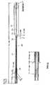
- FIG. 1is a side elevational view of a percutaneous access sheath.
- FIG. 2is a side elevational view of a insertion sheath.
- FIG. 3illustrates the percutaneous access sheath in a reduced cross-section configuration and inserted into the insertion sheath.
- FIG. 4is a side elevational view of an access sheath expansion catheter.
- FIG. 5is an enlarged view of the distal end of the expansion catheter.
- FIG. 6is an enlarged view of the proximal end of the expansion catheter.
- FIG. 7illustrates the percutaneous access sheath assembly, with the expansion catheter inserted into the structure illustrated in FIG. 3 .
- FIG. 8is a side elevational view of a bone anchor.
- FIG. 9is a side elevational view of the bone anchor of FIG. 8 , rotated 90° about is longitudinal axis.
- FIG. 10is a longitudinal cross-sectional view of the bone anchor of FIG. 9 .
- FIG. 11is a side elevational view of an alternative embodiment of a bone anchor.
- FIG. 12-15illustrate one embodiment of a method of threading a guide wire through the portals of bone anchors that have been implanted into adjacent vertebrae in a vertebral column.
- FIG. 1is an overview of the percutaneous access sheath 100 . It generally comprises an elongate tubular body with an axial lumen, and is designed to provide percutaneous access to a diagnostic or treatment site in the body.
- the elongate tubular bodyhas a proximal section and a distal section 110 .
- the length of these two sectionscan be varied according to clinical need, as will be understood by those skilled in the art with reference to this disclosure.
- the distal section 110is expandable from a first, smaller cross-sectional profile to a second, larger cross-sectional profile.
- the first, smaller cross-sectional profile of the distal section 110eases its insertion into the percutaneous treatment site.
- the distal section 110is expanded to a second, larger cross-sectional profile to provide a larger passageway for surgical instruments to reach the percutaneous treatment site.
- the percutaneous access sheath 100is made of a double-layered co-extruded tubing 102 , with an inner layer 104 and an outer layer 106 .
- the inner layer 104defines a lumen 108 .
- the inner layer 104extends further distally than the outer layer 106 , such that the distal section 110 of the tubing 102 is of a single layer, the inner layer 104 .
- the inner layer 104may be made of PTFE and the outer layer 106 may be made of HDPE. Other suitable materials, such as nylon, PEBAX or PEEK, may be used for either layer.
- the distal section 110is creased, folded inwards, and collapsed from a larger to a smaller cross-sectional profile to ease its insertion.
- the distal section 110is inserted through adjacent bone screws or anchors. Its length is thus determined by the distance between such adjacent bone screws, and is generally in the range of 4-12 cm.
- the proximal end 112 of the tubing 102is flared and fitted onto a handle 114 .
- a distal cap 116may be threaded onto the handle 114 to secure the proximal end 112 of the tubing 102 .
- a proximal cap 118may be threaded onto the handle 114 .
- the overall length of the tubing 102depends on the distance between the insertion and treatment locations, and is generally in the range of 15-60 cm for orthopedic fixation surgery of the vertebrae. In the illustrated embodiment the length of the tubing is approximately 20 cm, with the distal section 110 accounting for approximately half of that length.
- FIG. 2is an overview of the insertion sheath 200 . It is preferably made of a thin, smooth and flexible material.
- the insertion sheath 200has a proximal section and a distal, restraint section 210 .
- the restraint section 210has a smaller cross-sectional profile than the proximal section of the insertion sheath 200 .
- the restraint section 210is adapted to restrain the distal section 110 of the percutaneous access sheath 100 in its smaller cross-sectional profile. This is achieved by inserting the percutaneous access sheath 100 into the insertion sheath 200 such that the distal section 110 of the percutaneous access sheath 100 lies within the restraint section 210 of the insertion sheath 200 .
- the insertion sheath 200may be made of PTFE.
- the proximal end 202 of the insertion sheath 200terminates at a pull tab 204 , which may be formed by a threaded luer lock.
- the insertion sheath 200is provided with a slit 206 near its proximal end 202 .
- the insertion sheath 200tapers at a first tapering point 208 into a restraint section 210 , which tapers again into the distal tip 212 .
- the restraint section 210restrains the distal section 110 of the percutaneous access sheath 100 in its smaller cross-sectional profile.
- the length of the restraint section 210is approximately the same as or slightly longer than the distal section 110 , and generally falls in the range of 4-13 cm.
- the diameter of the restraint section 210is preferably smaller than the diameter of the eye of the bone screw used, as discussed below.
- the insertion sheath 200may be perforated or otherwise provided with a tear line distally from the first tapering point 208 to its distal tip 212 .
- the distance between the slit 206 and the distal tip 212is generally approximately equal to or slightly shorter than the length of the tubing 102 , and thus is generally in the range of 12-57 cm. In the illustrated embodiment this distance is approximately 15 cm, and the overall length of the insertion sheath 200 is approximately 24 cm.
- an insertion sheath 200may not be necessary if the distal section 110 of the percutaneous access sheath 100 is made of a stretchable material that may be stretched from a first, smaller cross-sectional profile to a second, larger cross-sectional profile.
- the outer surface of the distal section 110is preferably made of a smooth material to facilitate the insertion of the percutaneous access sheath 100 into a treatment site.
- FIG. 4is an overview of the deployment catheter 300 . It is provided with an expansion element such as balloon 310 at its distal end.
- the deployment catheter 300is inserted into the lumen 108 of the percutaneous access sheath 100 such that the balloon 310 is arranged within the distal section 110 .
- the balloon 310may be inflated to expand the distal section 110 from its first, smaller cross-sectional profile to its second, larger cross-sectional profile following the insertion of the percutaneous access sheath 100 into a treatment site.
- An inner tube 302extends the entire length of the deployment catheter 300 .
- a guide wire lumen 304is defined by the interior of the inner tube 302 .
- the deployment catheter 300can travel along a guide wire extending through the guide wire lumen 304 .
- the inner tube 302carries coaxially on its exterior an outer tube 306 .
- the outer tube 306terminates proximally into the distal end of a handle 308 , and distally into the proximal end of a balloon 310 .
- the balloon 310may be made of PET.
- the handle 308may be provided with an optional support tube 312 extending from its distal end and over a proximal section of the outer tube 306 , to increase the rigidity of the deployment catheter 300 during insertion.
- This support tube 312may be made of aluminum.
- FIG. 5is an enlarged view of the distal end of the deployment catheter 300 .
- Both the inner tube 302 and the guide wire lumen 304extend through the distal end 314 of the balloon 310 .
- the inner tube 302carries coaxially on its exterior a marker ring 316 near the distal end 314 of the balloon 310 .
- the marker ring 316may be carried by the distal end 314 of the balloon 310 .
- the marker ring 316is preferably made of gold, tantalum, or another radio-opaque material. Additional marker rings may be provided in the balloon 310 to aid in visualizing its location.
- a balloon inflation lumen 318defined in the space between the inner tube 302 and the outer tube 306 , communicates with the interior of the balloon 310 .
- the balloon 310may be inflated to expand the distal section 110 of the percutaneous access sheath 100 from its first, smaller cross-sectional profile to its second, larger cross-sectional profile.
- the length of the balloon 310is approximately equal to or slightly longer than the length of the distal section 110 . In the illustrated embodiment the length of the balloon 310 is approximately 10 cm.
- FIG. 6is an enlarged view of the proximal end of the deployment catheter 300 .
- Both the inner tube 302 and the guide wire lumen 304extend through the proximal end of the handle 308 .
- the balloon inflation lumen 318defined in the space between the inner tube 302 and the outer tube 306 , opens into a port 320 in the handle 308 .
- a stopper 322supports the inner tube 302 within the handle 308 and prevents the balloon inflation lumen 318 from communicating with the space 324 in the main branch of the handle 308 .
- the port 320communicates via the balloon inflation lumen 318 with the interior of the balloon.
- a pumpmay be connected to the port 320 to inflate or deflate the balloon. To enable visualization of the state of the balloon, it may be inflated with contrast media.
- FIG. 7illustrates the percutaneous access sheath assembly 150 .
- the percutaneous access sheath assembly 150comprises the percutaneous access sheath 100 , the insertion sheath 200 and the deployment catheter 300 . It is assembled by inserting the deployment catheter 300 into the percutaneous access sheath 100 and inserting the percutaneous access sheath 100 into the insertion sheath 200 such as via the slit 206 or other proximal opening provided near its proximal end 202 .
- the balloon 310 of the deployment catheter 300is deflated, folded and inserted into the distal section 110 of the access sheath 100 .
- the distal section 110is creased and folded inwards to decrease its effective diameter, and inserted into the restraint section 210 of the insertion sheath 200 .
- the balloon 310is approximately the same length as or just longer than the distal section 110 and the restraint section 210 .
- FIGS. 8-11illustrate one embodiment of a bone anchor 410 as mentioned above. It is provided with at least one connector 422 at or near its proximal end (or top end, as illustrated). This connector 422 is used to engage an orthopedic spinal stabilization implant that is formed in situ, as discussed below.
- the connector 422is preferably an aperture 422 , to achieve a more secure engagement.
- the percutaneous access sheath 100extends through the apertures 422 of two or more bone anchors 410 to establish a passageway to facilitate the insertion of a formed in situ orthopedic spinal stabilization implant.
- the percutaneous access sheath 100is extended through the aperture 422 of a first bone anchor 410 , then through the aperture 422 of a second bone anchor 410 .
- the first bone anchor 410is preferably implanted within a first bone.
- the second bone anchor 410may be implanted within the second bone.
- the bonesmay be adjacent vertebral bodies or vertebrae, or first and second vertebrae spaced apart by one or more intermediate vertebrae. The clinical procedure is described in further detail below.
- the bone anchors 410 of FIGS. 8-11are made of a biocompatible material such as titanium or stainless steel. Alternatively, the bone anchors 410 may be made of a composite material. The bone anchors 410 may also be made of a suitable medical grade polymer. In one embodiment, the bone anchors 410 have a length between about 40 mm and 60 mm, preferably about 50 mm. However, the actual length is dependent on the location of the fracture, size of patient, etc.
- the bone anchor 410comprises a proximal portion 412 having a proximal end 414 and a distal portion 416 having a distal end 418 .
- the proximal portion 412typically comprises a head 420 and a portal 422 .
- the head 420comprises a proximal portion 424 configured to mate with the tip of a screwdriver.
- the head 420may comprise a standard or Phillips slot for mating with the screwdriver.
- a variety of slot configurationsare also suitable, such as hexagonal, Torx, rectangular, triangular, curved, or any other suitable shape.
- Platform 434having a plurality of substantially flat sides, such as a hexagonal platform, configured to mate with a corresponding depression in the distal end of a screwdriver.
- Platform 434may come in a variety of shapes suitable mating with a screwdriver.
- the portal 422 of the bone anchor 410may extend through the head 420 and is generally between about 4 mm and 8 mm in diameter, preferably about 6 mm to about 8 mm in diameter.
- the portal 422may be of any suitable shape; however, the portal 422 is preferably round to facilitate the insertion of the percutaneous tube 100 as well as the in situ forming orthopedic spinal stabilization implant.
- the distal portion 416 of the bone anchor 410typically comprises threads 426 and a sharp tip 428 .
- the bone anchor 410also preferably comprises a central lumen 430 extending coaxially through the length of the bone anchor 410 from its proximal end 414 to its distal end 418 and configured to receive a guidewire.
- the bone anchor 410may also include one or more perforations 432 , as shown in FIG. 11 . These perforations 432 are in communication with the central lumen 430 of the bone anchor 410 .
- the perforations 432may be aligned axially, as illustrated, or may be staggered axially.
- the perforations 432permit bone to grow into bone anchor 410 , stabilizing bone anchor 410 within the bone. Additionally, bone matrix material such as a hydroxyapatite preparation can be injected into the central lumen 430 and through the perforations 432 to promote bone in-growth.
- a smooth channelis first established between two or more adjacent bone anchors to facilitate the passage of another deployment catheter carrying an inflatable orthopedic fixation device at its distal end. While the method is disclosed and depicted with reference to only two vertebrae, one of which is either unstable, separated or displaced and the other of which is neither unstable, separated or displaced, the method can also be applied to three or more vertebrae simultaneously. Further, the method can be used to stabilize the L 5 vertebrae, using the cranial-ward portion of the sacrum as the “vertebrae” with which L 5 is anchored.
- the methodis disclosed and depicted as applied on the left side of the vertebral column, the method can also be applied on the right side of the vertebral column or, preferably, on both sides of the vertebral column, as will be understood by those skilled in the art with reference to this disclosure.
- Other applicationsinclude the stabilization of other bones and skeletal elements of the body.
- FIG. 12illustrates bone anchors 410 that have been inserted through the periosteal surface and into the anterior vertebral body or another suitable portion of the vertebrae 500 and 502 .
- bone matrix materialsuch as a hydroxyapatite preparation can be injected into the central lumen 430 of a bone anchors 410 and through its perforations (not visible in this figure) to promote bone in-growth.
- the bone anchors 410are arranged such that their portals 422 are substantially coaxial in relation to each other.
- a hollow needle 436is inserted percutaneously and advanced into the portal 422 of one of the bone anchors 410 , with the aid of fluoroscopy.
- the hollow needle 436may be 16 or 18 gauge. While the hollow needle 436 is shown engaging the bone screw 410 in the cranial-ward vertebrae 502 , it can alternatively first engage the bone screw 410 in the caudal-ward vertebrae 500 , as will be understood by those skilled in the art with reference to the disclosure.
- FIG. 13is an enlarged view of the distal end of the hollow needle 436 .
- a semi-rigid guide wire 438is introduced through the lumen of the hollow need 436 and the portal 422 of the bone anchor 410 in the cranial-ward vertebrae 502 .
- the hollow needle 436preferably has a Tuohy needle tip which causes the guide wire 438 to exit the hollow needle 436 perpendicularly to the central lumen 430 of the bone anchor 410 , or coaxially with the axis of the portal 422 of the bone anchor 410 .
- the bending of the guide wire 438 through the portal 422 of the bone anchor 410may be accomplished by an angled-tip modified Ross needle or another suitable structure as will be understood by those skilled in the art with reference to the disclosure.
- FIG. 14illustrates an optional guide wire directing device 440 , according to one aspect of the present invention, inserted percutaneously between the bone anchors 410 .
- the guide wire directing device 440may have a forked end used to direct the guide wire 438 through the portal 422 of the bone anchor 410 in the caudal-ward vertebrae 500 .
- a guide wire capture device 442such as a snare or forceps, may be inserted percutaneously caudal to the portal 422 of the bone anchor 410 in the caudal-ward vertebrae 500 .
- the guide wire capture device 442engages the distal end of the guide wire 438 after the guide wire 438 has passed through portal 422 of the bone anchor 410 in the caudal-ward vertebrae 500 , and pulls it through the skin dorsally, so that both ends of the guide wire 438 are secured.
- FIG. 15illustrates the guide wire 438 in place after the procedure described above in FIGS. 12-14 .
- the guide wire 438may be inserted into the guide wire lumen 304 of the deployment catheter 300 of the percutaneous access sheath assembly 150 .
- the entire assembly 150may travel over the guide wire 438 until its distal tapered portion is inserted through the portals 422 of the bone anchors 410 .
- the insertion sheath 200which is on the exterior of the percutaneous access sheath assembly 150 , facilitates the insertion because of its smooth, low profile exterior. As discussed above, it may be made of PTFE.
- the insertion sheath 200is removed. This may be accomplished by pulling on the pull tab 204 and tearing the insertion sheath 200 along the perforations, crease line, or other structure for facilitating tearing provided along its restraint section 210 . This may be facilitated by first partially inflating the balloon 310 of the deployment catheter 300 . As discussed above, the balloon 310 is arranged within the distal section 110 of the percutaneous access sheath 100 , which is itself arranged within the restraint section 210 of the insertion sheath 200 . Thus, inflating the balloon 310 causes the distal section 110 of the percutaneous access sheath 100 to expand, tearing the restraint section 210 of the insertion sheath 200 along its perforations.
- the balloon 310may be fully inflated to expand the distal section 110 of the percutaneous access sheath to its full cross-sectional profile. Afterwards the balloon 310 may be deflated to ease the removal of the deployment catheter 300 . As discussed above, the inflation and deflation of the balloon 310 may be done via a pump connected to the port 320 of the deployment catheter 300 , and preferably with contrast media being pumped, to better convey the state of the balloon.
- the percutaneous access sheath 100is inserted through the portals 422 of the bone anchors 410 .
- the establishment of this smooth channel through the portals 422 of the bone anchors 410facilitates the passage of another deployment catheter carrying an inflatable orthopedic fixation device at its distal end.
- An example of such a deployment catheter with an inflatable orthopedic fixation device at its distal end as well as the associated anchors and methodsare disclosed in U.S. patent application Ser. No. 10/161,554 filed on May 31, 2002, the disclosure of which is hereby incorporated by reference in its entirety.
Landscapes
- Health & Medical Sciences (AREA)
- Life Sciences & Earth Sciences (AREA)
- Surgery (AREA)
- Orthopedic Medicine & Surgery (AREA)
- General Health & Medical Sciences (AREA)
- Public Health (AREA)
- Biomedical Technology (AREA)
- Heart & Thoracic Surgery (AREA)
- Veterinary Medicine (AREA)
- Animal Behavior & Ethology (AREA)
- Engineering & Computer Science (AREA)
- Molecular Biology (AREA)
- Nuclear Medicine, Radiotherapy & Molecular Imaging (AREA)
- Medical Informatics (AREA)
- Neurology (AREA)
- Pathology (AREA)
- Hematology (AREA)
- Pulmonology (AREA)
- Anesthesiology (AREA)
- Biophysics (AREA)
- Prostheses (AREA)
- Surgical Instruments (AREA)
Abstract
Description
Claims (32)
Priority Applications (11)
| Application Number | Priority Date | Filing Date | Title |
|---|---|---|---|
| US10/188,732US7329268B2 (en) | 2002-07-02 | 2002-07-02 | Expandable percutaneous sheath |
| JP2004519695AJP4344317B2 (en) | 2002-07-02 | 2003-07-01 | Inflatable percutaneous sheath |
| EP03763054AEP1539007A4 (en) | 2002-07-02 | 2003-07-01 | Expandable percutaneous sheath |
| EP10193167.3AEP2305156B1 (en) | 2002-07-02 | 2003-07-01 | Expandable percutaneous sheath |
| KR1020057000092AKR101028295B1 (en) | 2002-07-02 | 2003-07-01 | Expandable Transdermal Sheath |
| CNB038191644ACN100518682C (en) | 2002-07-02 | 2003-07-01 | Expandable percutaneous sheath |
| CA002491493ACA2491493A1 (en) | 2002-07-02 | 2003-07-01 | Expandable percutaneous sheath |
| PCT/US2003/020550WO2004004584A1 (en) | 2002-07-02 | 2003-07-01 | Expandable percutaneous sheath |
| AU2003251745AAU2003251745B2 (en) | 2002-07-02 | 2003-07-01 | Expandable percutaneous sheath |
| US11/200,144US8034072B2 (en) | 2002-07-02 | 2005-08-10 | Expandable percutaneous sheath |
| US11/331,140US7914555B2 (en) | 2002-07-02 | 2006-01-13 | Expandable percutaneous sheath |
Applications Claiming Priority (1)
| Application Number | Priority Date | Filing Date | Title |
|---|---|---|---|
| US10/188,732US7329268B2 (en) | 2002-07-02 | 2002-07-02 | Expandable percutaneous sheath |
Related Child Applications (1)
| Application Number | Title | Priority Date | Filing Date |
|---|---|---|---|
| US11/200,144ContinuationUS8034072B2 (en) | 2002-07-02 | 2005-08-10 | Expandable percutaneous sheath |
Publications (2)
| Publication Number | Publication Date |
|---|---|
| US20040006344A1 US20040006344A1 (en) | 2004-01-08 |
| US7329268B2true US7329268B2 (en) | 2008-02-12 |
Family
ID=29999541
Family Applications (3)
| Application Number | Title | Priority Date | Filing Date |
|---|---|---|---|
| US10/188,732Expired - LifetimeUS7329268B2 (en) | 2002-07-02 | 2002-07-02 | Expandable percutaneous sheath |
| US11/200,144Expired - Fee RelatedUS8034072B2 (en) | 2002-07-02 | 2005-08-10 | Expandable percutaneous sheath |
| US11/331,140Expired - Fee RelatedUS7914555B2 (en) | 2002-07-02 | 2006-01-13 | Expandable percutaneous sheath |
Family Applications After (2)
| Application Number | Title | Priority Date | Filing Date |
|---|---|---|---|
| US11/200,144Expired - Fee RelatedUS8034072B2 (en) | 2002-07-02 | 2005-08-10 | Expandable percutaneous sheath |
| US11/331,140Expired - Fee RelatedUS7914555B2 (en) | 2002-07-02 | 2006-01-13 | Expandable percutaneous sheath |
Country Status (8)
| Country | Link |
|---|---|
| US (3) | US7329268B2 (en) |
| EP (2) | EP1539007A4 (en) |
| JP (1) | JP4344317B2 (en) |
| KR (1) | KR101028295B1 (en) |
| CN (1) | CN100518682C (en) |
| AU (1) | AU2003251745B2 (en) |
| CA (1) | CA2491493A1 (en) |
| WO (1) | WO2004004584A1 (en) |
Cited By (31)
| Publication number | Priority date | Publication date | Assignee | Title |
|---|---|---|---|---|
| US20050216018A1 (en)* | 2004-03-29 | 2005-09-29 | Sennett Andrew R | Orthopedic surgery access devices |
| US20060052750A1 (en)* | 2004-09-09 | 2006-03-09 | Jay Lenker | Expandable transluminal sheath |
| US20060200188A1 (en)* | 2003-12-05 | 2006-09-07 | Nance Edward J | Expandable percutaneous sheath |
| US20070021768A1 (en)* | 2005-06-03 | 2007-01-25 | Nance Edward J | Expandable percutaneous sheath |
| US20080208320A1 (en)* | 2006-12-15 | 2008-08-28 | Francisca Tan-Malecki | Delivery Apparatus and Methods for Vertebrostenting |
| US20090287182A1 (en)* | 2008-05-14 | 2009-11-19 | Onset Medical Corporation | Expandable iliac sheath and method of use |
| US20090326538A1 (en)* | 2006-12-15 | 2009-12-31 | Sennett Andrew R | Devices and methods for fracture reduction |
| US20100094392A1 (en)* | 2008-10-10 | 2010-04-15 | Edwards Lifesciences Corporation | Expandable Sheath for Introducing an Endovascular Delivery Device into a Body |
| US20100145267A1 (en)* | 2008-11-10 | 2010-06-10 | Onset Medical Corporation | Expandable spinal sheath and method of use |
| US20100160947A1 (en)* | 2008-12-18 | 2010-06-24 | IMDS, Inc. | Systems and methods for dilation and dissection of tissues |
| US20110237898A1 (en)* | 2008-12-18 | 2011-09-29 | Medicinelodge, Inc. Dba Imds Co-Innovation | Lateral access system for the lumbar spine |
| US8597277B2 (en) | 2004-09-09 | 2013-12-03 | Onset Medical Corporation | Expandable transluminal sheath |
| US8728162B2 (en) | 2010-04-15 | 2014-05-20 | Osteomed, Llc | Direct lateral spine system instruments, implants and associated methods |
| US8790387B2 (en) | 2008-10-10 | 2014-07-29 | Edwards Lifesciences Corporation | Expandable sheath for introducing an endovascular delivery device into a body |
| US9192751B2 (en) | 2012-10-26 | 2015-11-24 | Medtronic, Inc. | Elastic introducer sheath |
| US9241735B2 (en) | 2003-12-05 | 2016-01-26 | Onset Medical Corporation | Expandable percutaneous sheath |
| US9387314B2 (en) | 2008-05-14 | 2016-07-12 | Onset Medical Corporation | Expandable iliac sheath and method of use |
| US9480485B2 (en) | 2006-12-15 | 2016-11-01 | Globus Medical, Inc. | Devices and methods for vertebrostenting |
| US20170252062A1 (en)* | 2016-03-04 | 2017-09-07 | Boston Scientific Scimed, Inc. | Introducer with expandable capabilities |
| US9907931B2 (en) | 2012-10-26 | 2018-03-06 | Medtronic, Inc. | Elastic introducer sheath |
| US10327896B2 (en) | 2015-04-10 | 2019-06-25 | Edwards Lifesciences Corporation | Expandable sheath with elastomeric cross sectional portions |
| US10792471B2 (en) | 2015-04-10 | 2020-10-06 | Edwards Lifesciences Corporation | Expandable sheath |
| US10918829B2 (en) | 2015-01-22 | 2021-02-16 | Boston Scientific Scimed, Inc. | Fully compliant large bore expandable sheath |
| US11129959B2 (en) | 2018-02-15 | 2021-09-28 | Boston Scientific Scimed, Inc. | Introducer with expandable capabilities |
| US11166709B2 (en) | 2016-08-23 | 2021-11-09 | Stryker European Operations Holdings Llc | Instrumentation and methods for the implantation of spinal implants |
| US11191532B2 (en) | 2018-03-30 | 2021-12-07 | Stryker European Operations Holdings Llc | Lateral access retractor and core insertion |
| US11413029B2 (en) | 2018-10-24 | 2022-08-16 | Stryker European Operations Holdings Llc | Anterior to psoas instrumentation |
| US11565093B2 (en) | 2018-09-10 | 2023-01-31 | Boston Scientific Scimed, Inc. | Introducer with expandable capabilities |
| US11564674B2 (en) | 2019-11-27 | 2023-01-31 | K2M, Inc. | Lateral access system and method of use |
| US11786695B2 (en) | 2018-07-25 | 2023-10-17 | Edwards Lifesciences Corporation | Methods of making an expandable sheath |
| US12194256B2 (en) | 2015-04-10 | 2025-01-14 | Edwards Lifesciences Corporation | Expandable sheath |
Families Citing this family (111)
| Publication number | Priority date | Publication date | Assignee | Title |
|---|---|---|---|---|
| US6477400B1 (en) | 1998-08-20 | 2002-11-05 | Sofamor Danek Holdings, Inc. | Fluoroscopic image guided orthopaedic surgery system with intraoperative registration |
| EP1496975B1 (en)* | 2002-04-25 | 2009-04-08 | The Board of Trustees of The Leland Stanford Junior University | Expandable guide sheath |
| US8956280B2 (en) | 2002-05-30 | 2015-02-17 | Intuitive Surgical Operations, Inc. | Apparatus and methods for placing leads using direct visualization |
| US7329268B2 (en) | 2002-07-02 | 2008-02-12 | Warsaw Orthopedic, Inc. | Expandable percutaneous sheath |
| US8425549B2 (en)* | 2002-07-23 | 2013-04-23 | Reverse Medical Corporation | Systems and methods for removing obstructive matter from body lumens and treating vascular defects |
| US7309334B2 (en)* | 2002-07-23 | 2007-12-18 | Von Hoffmann Gerard | Intracranial aspiration catheter |
| US7655021B2 (en)* | 2003-03-10 | 2010-02-02 | Boston Scientific Scimed, Inc. | Dilator with expandable member |
| TWI315010B (en)* | 2003-03-31 | 2009-09-21 | Sharp Corporatio | Liquid crystal display device and method of manufacturing the same |
| US7591832B2 (en)* | 2003-04-24 | 2009-09-22 | Medtronic, Inc. | Expandable guide sheath and apparatus with distal protection and methods for use |
| US7473267B2 (en)* | 2003-04-25 | 2009-01-06 | Warsaw Orthopedic, Inc. | System and method for minimally invasive posterior fixation |
| WO2005023358A1 (en)* | 2003-09-03 | 2005-03-17 | Acumen Medical, Inc. | Expandable sheath for delivering instruments and agents into a body lumen |
| US8002798B2 (en) | 2003-09-24 | 2011-08-23 | Stryker Spine | System and method for spinal implant placement |
| US7955355B2 (en) | 2003-09-24 | 2011-06-07 | Stryker Spine | Methods and devices for improving percutaneous access in minimally invasive surgeries |
| ATE475448T1 (en)* | 2003-10-03 | 2010-08-15 | Medtronic Inc | EXPANDABLE GUIDE LOCK AND DEVICE |
| US9055934B2 (en)* | 2004-08-26 | 2015-06-16 | Zimmer Spine, Inc. | Methods and apparatus for access to and/or treatment of the spine |
| US7527638B2 (en) | 2003-12-16 | 2009-05-05 | Depuy Spine, Inc. | Methods and devices for minimally invasive spinal fixation element placement |
| US20050209627A1 (en)* | 2004-03-18 | 2005-09-22 | Kick George F | Expandable medical access device |
| US7699864B2 (en)* | 2004-03-18 | 2010-04-20 | Onset Medical Corporation | Expandable medical access device |
| US7567834B2 (en)* | 2004-05-03 | 2009-07-28 | Medtronic Navigation, Inc. | Method and apparatus for implantation between two vertebral bodies |
| US20060041270A1 (en)* | 2004-05-07 | 2006-02-23 | Jay Lenker | Medical access sheath |
| US8142462B2 (en) | 2004-05-28 | 2012-03-27 | Cavitech, Llc | Instruments and methods for reducing and stabilizing bone fractures |
| US7776073B2 (en)* | 2004-06-30 | 2010-08-17 | Depuy Spine, Inc. | In-situ formed posterolateral fusion system |
| US20060135962A1 (en)* | 2004-09-09 | 2006-06-22 | Kick George F | Expandable trans-septal sheath |
| WO2006034436A2 (en)* | 2004-09-21 | 2006-03-30 | Stout Medical Group, L.P. | Expandable support device and method of use |
| US7875049B2 (en)* | 2004-10-04 | 2011-01-25 | Medtronic, Inc. | Expandable guide sheath with steerable backbone and methods for making and using them |
| US7993350B2 (en)* | 2004-10-04 | 2011-08-09 | Medtronic, Inc. | Shapeable or steerable guide sheaths and methods for making and using them |
| US8226690B2 (en) | 2005-07-22 | 2012-07-24 | The Board Of Trustees Of The Leland Stanford Junior University | Systems and methods for stabilization of bone structures |
| US20090228045A1 (en)* | 2004-10-20 | 2009-09-10 | Stanley Kyle Hayes | Dynamic rod |
| US8162985B2 (en)* | 2004-10-20 | 2012-04-24 | The Board Of Trustees Of The Leland Stanford Junior University | Systems and methods for posterior dynamic stabilization of the spine |
| US8025680B2 (en)* | 2004-10-20 | 2011-09-27 | Exactech, Inc. | Systems and methods for posterior dynamic stabilization of the spine |
| US8267969B2 (en)* | 2004-10-20 | 2012-09-18 | Exactech, Inc. | Screw systems and methods for use in stabilization of bone structures |
| US7935134B2 (en) | 2004-10-20 | 2011-05-03 | Exactech, Inc. | Systems and methods for stabilization of bone structures |
| US20070239159A1 (en)* | 2005-07-22 | 2007-10-11 | Vertiflex, Inc. | Systems and methods for stabilization of bone structures |
| WO2006058079A2 (en)* | 2004-11-22 | 2006-06-01 | Endius, Inc. | Expandable device for providing access to the spine |
| US20060253102A1 (en)* | 2004-12-21 | 2006-11-09 | Nance Edward J | Non-expandable transluminal access sheath |
| US20060259061A1 (en)* | 2005-04-22 | 2006-11-16 | Kick George F | Expandable sheath for percutaneous upper gastrointestinal tract access |
| WO2006116761A2 (en)* | 2005-04-27 | 2006-11-02 | Stout Medical Group, L.P. | Expandable support device and methods of use |
| US8177817B2 (en) | 2005-05-18 | 2012-05-15 | Stryker Spine | System and method for orthopedic implant configuration |
| US20070021648A1 (en)* | 2005-06-29 | 2007-01-25 | Jay Lenker | Transluminal sheath hub |
| US20070010848A1 (en)* | 2005-07-11 | 2007-01-11 | Andrea Leung | Systems and methods for providing cavities in interior body regions |
| WO2007008667A2 (en)* | 2005-07-11 | 2007-01-18 | Kyphon, Inc. | Systems and methods for providing cavities in interior body regions |
| US20070032703A1 (en)* | 2005-07-11 | 2007-02-08 | Sankaran Meera L | Radially expansive surgical instruments for tissue retraction and methods for using the same |
| EP1903949A2 (en)* | 2005-07-14 | 2008-04-02 | Stout Medical Group, L.P. | Expandable support device and method of use |
| KR100660121B1 (en) | 2005-07-18 | 2006-12-20 | (주)태연메디칼 | Spinal Restoration Procedure |
| US8523865B2 (en) | 2005-07-22 | 2013-09-03 | Exactech, Inc. | Tissue splitter |
| US7575569B2 (en)* | 2005-08-16 | 2009-08-18 | Medtronic, Inc. | Apparatus and methods for delivering stem cells and other agents into cardiac tissue |
| US7637902B2 (en)* | 2005-11-23 | 2009-12-29 | Medtronic, Inc. | Slittable and peelable sheaths and methods for making and using them |
| EP1981422B1 (en)* | 2006-02-06 | 2018-10-24 | Stryker European Holdings I, LLC | Rod contouring apparatus for percutaneous pedicle screw extension |
| EP2023864B1 (en) | 2006-05-01 | 2019-07-10 | Stout Medical Group, L.P. | Expandable support device |
| US7686809B2 (en) | 2006-09-25 | 2010-03-30 | Stryker Spine | Rod inserter and rod with reduced diameter end |
| US8096996B2 (en) | 2007-03-20 | 2012-01-17 | Exactech, Inc. | Rod reducer |
| US8337518B2 (en) | 2006-12-20 | 2012-12-25 | Onset Medical Corporation | Expandable trans-septal sheath |
| US7722568B2 (en)* | 2007-01-29 | 2010-05-25 | Onset Medical Corporation | Expandable intra-aortic balloon pump sheath |
| WO2008121888A1 (en) | 2007-03-30 | 2008-10-09 | Onset Medical Corporation | Expandable trans-septal sheath |
| AU2008239408B2 (en)* | 2007-04-11 | 2013-07-04 | Covidien Lp | Endoscopic/laparoscopic introducer sleeve |
| US20090131952A1 (en) | 2007-05-21 | 2009-05-21 | Brian Schumacher | Delivery system and method for inflatable devices |
| US20090024158A1 (en)* | 2007-07-16 | 2009-01-22 | Zimmer Spine, Inc. | Access Port Expander And Method |
| US8372131B2 (en)* | 2007-07-16 | 2013-02-12 | Power Ten , LLC | Surgical site access system and deployment device for same |
| US8728153B2 (en)* | 2008-05-14 | 2014-05-20 | Onset Medical Corporation | Expandable transapical sheath and method of use |
| US8070694B2 (en)* | 2008-07-14 | 2011-12-06 | Medtronic Vascular, Inc. | Fiber based medical devices and aspiration catheters |
| US20100191286A1 (en)* | 2008-10-03 | 2010-07-29 | Butler Jesse P | Facet compression system and related surgical methods |
| WO2010056895A1 (en) | 2008-11-12 | 2010-05-20 | Stout Medical Group, L.P. | Fixation device and method |
| US20100211176A1 (en) | 2008-11-12 | 2010-08-19 | Stout Medical Group, L.P. | Fixation device and method |
| US8246682B2 (en)* | 2008-12-16 | 2012-08-21 | Depuy Spine, Inc. | Methods and devices for expanding a spinal canal using balloons |
| WO2010094032A2 (en) | 2009-02-16 | 2010-08-19 | Aoi Medical Inc. | Trauma nail accumulator |
| US8926508B2 (en)* | 2009-12-17 | 2015-01-06 | Covidien Lp | Access assembly with dual anchor and seal capabilities |
| US8535380B2 (en) | 2010-05-13 | 2013-09-17 | Stout Medical Group, L.P. | Fixation device and method |
| WO2011150049A1 (en)* | 2010-05-26 | 2011-12-01 | Farrell Eric D | Bone screw introducing sleeve |
| BR112013003333B1 (en) | 2010-08-12 | 2021-12-28 | C.R. Bard, Inc | CATHETER SET INCLUDING DISTAL PORTION STABILITY CHARACTERISTICS |
| US10238833B2 (en) | 2010-08-12 | 2019-03-26 | C. R. Bard, Inc. | Access port and catheter assembly including catheter distal portion stability features |
| EP2608747A4 (en) | 2010-08-24 | 2015-02-11 | Flexmedex Llc | Support device and method for use |
| US9149286B1 (en) | 2010-11-12 | 2015-10-06 | Flexmedex, LLC | Guidance tool and method for use |
| US10779855B2 (en) | 2011-08-05 | 2020-09-22 | Route 92 Medical, Inc. | Methods and systems for treatment of acute ischemic stroke |
| EP4101399B1 (en) | 2011-08-05 | 2025-04-09 | Route 92 Medical, Inc. | System for treatment of acute ischemic stroke |
| EP2747682A4 (en) | 2011-08-23 | 2015-01-21 | Flexmedex Llc | Tissue removal device and method |
| US8814832B1 (en)* | 2013-02-15 | 2014-08-26 | Ibrahim Rashid Al-Rashdan | Expandable sheath and system for intravascular insertion of a medical implement using the same |
| CA2846149C (en) | 2013-03-14 | 2018-03-20 | Stryker Spine | Systems and methods for percutaneous spinal fusion |
| US9827020B2 (en) | 2013-03-14 | 2017-11-28 | Stryker European Holdings I, Llc | Percutaneous spinal cross link system and method |
| US9408716B1 (en) | 2013-12-06 | 2016-08-09 | Stryker European Holdings I, Llc | Percutaneous posterior spinal fusion implant construction and method |
| US9744050B1 (en) | 2013-12-06 | 2017-08-29 | Stryker European Holdings I, Llc | Compression and distraction system for percutaneous posterior spinal fusion |
| US10159579B1 (en) | 2013-12-06 | 2018-12-25 | Stryker European Holdings I, Llc | Tubular instruments for percutaneous posterior spinal fusion systems and methods |
| US9265512B2 (en) | 2013-12-23 | 2016-02-23 | Silk Road Medical, Inc. | Transcarotid neurovascular catheter |
| US9820761B2 (en) | 2014-03-21 | 2017-11-21 | Route 92 Medical, Inc. | Rapid aspiration thrombectomy system and method |
| CA3008161C (en) | 2014-12-09 | 2023-09-26 | John A. Heflin | Spine alignment system |
| CN119949953A (en) | 2015-02-04 | 2025-05-09 | 92号医疗公司 | Intravascular access system, dilator and system including dilator |
| US11065019B1 (en) | 2015-02-04 | 2021-07-20 | Route 92 Medical, Inc. | Aspiration catheter systems and methods of use |
| US10426497B2 (en) | 2015-07-24 | 2019-10-01 | Route 92 Medical, Inc. | Anchoring delivery system and methods |
| US10080652B2 (en) | 2015-03-13 | 2018-09-25 | Boston Scientific Scimed, Inc. | Prosthetic heart valve having an improved tubular seal |
| US11253266B2 (en)* | 2015-08-25 | 2022-02-22 | Endoshape, Inc. | Sleeve for delivery of embolic coil |
| US10716915B2 (en) | 2015-11-23 | 2020-07-21 | Mivi Neuroscience, Inc. | Catheter systems for applying effective suction in remote vessels and thrombectomy procedures facilitated by catheter systems |
| US20170189059A1 (en)* | 2016-01-06 | 2017-07-06 | Boston Scientific Scimed, Inc. | Percutaneous access device |
| EP3405126A1 (en)* | 2016-01-21 | 2018-11-28 | Boston Scientific Scimed, Inc. | Medical devices and related methods of use |
| US10485582B2 (en)* | 2016-07-22 | 2019-11-26 | Intuitive Surgical Operations, Inc. | Cannulas having body wall retention features, and related systems and methods |
| US11229445B2 (en) | 2016-10-06 | 2022-01-25 | Mivi Neuroscience, Inc. | Hydraulic displacement and removal of thrombus clots, and catheters for performing hydraulic displacement |
| CN110392591B (en) | 2017-01-10 | 2022-06-03 | 92号医疗公司 | Aspiration catheter system and method of use |
| US10864350B2 (en) | 2017-01-20 | 2020-12-15 | Route 92 Medical, Inc. | Single operator intracranial medical device delivery systems and methods of use |
| US10912919B2 (en) | 2017-01-23 | 2021-02-09 | Edwards Lifesciences Corporation | Expandable sheath |
| US10918456B2 (en)* | 2017-02-03 | 2021-02-16 | Sony Olympus Medical Solutions Inc. | Protective cover and medical observation apparatus |
| US10799685B2 (en) | 2017-03-09 | 2020-10-13 | Edwards Lifesciences Corporation | Expandable sheath with longitudinally extending reinforcing members |
| US11026719B2 (en) | 2017-05-15 | 2021-06-08 | Boston Scientific Scimed, Inc. | Radially expandable introducer sheath |
| US11234723B2 (en) | 2017-12-20 | 2022-02-01 | Mivi Neuroscience, Inc. | Suction catheter systems for applying effective aspiration in remote vessels, especially cerebral arteries |
| US10478535B2 (en) | 2017-05-24 | 2019-11-19 | Mivi Neuroscience, Inc. | Suction catheter systems for applying effective aspiration in remote vessels, especially cerebral arteries |
| CN110753566A (en)* | 2017-06-13 | 2020-02-04 | 波士顿科学国际有限公司 | Introducer with expandable capability |
| CN112105318B (en) | 2018-04-09 | 2024-04-16 | 爱德华兹生命科学公司 | Expandable sheath |
| JP7616642B2 (en) | 2018-05-17 | 2025-01-17 | ルート92メディカル・インコーポレイテッド | Suction catheter system and method of use |
| CN108578806A (en)* | 2018-05-17 | 2018-09-28 | 上海军慧医疗管理有限公司 | It is a kind of that disposably percutaneously peritoneal dialysis catheters set effective sting device |
| CN109938810A (en)* | 2019-03-27 | 2019-06-28 | 深圳市擎源医疗器械有限公司 | Needle Assembly and Balloon Catheter Kit |
| US11617865B2 (en) | 2020-01-24 | 2023-04-04 | Mivi Neuroscience, Inc. | Suction catheter systems with designs allowing rapid clearing of clots |
| WO2022076893A1 (en) | 2020-10-09 | 2022-04-14 | Route 92 Medical, Inc. | Aspiration catheter systems and methods of use |
| CN118845102B (en)* | 2024-09-25 | 2025-02-11 | 湖南省华芯医疗器械有限公司 | Sheath assembly, endoscope system and method of use thereof |
| CN118845101B (en)* | 2024-09-25 | 2025-03-07 | 湖南省华芯医疗器械有限公司 | Introducer sheath and sheath assembly |
Citations (21)
| Publication number | Priority date | Publication date | Assignee | Title |
|---|---|---|---|---|
| US4401433A (en) | 1980-06-13 | 1983-08-30 | Luther Ronald B | Apparatus for advancing oversized catheter through cannula, and the like |
| US4451256A (en) | 1981-05-06 | 1984-05-29 | Intermedicat Gmbh | Catheter set |
| US4710181A (en) | 1985-06-11 | 1987-12-01 | Genus Catheter Technologies, Inc. | Variable diameter catheter |
| US4738666A (en) | 1985-06-11 | 1988-04-19 | Genus Catheter Technologies, Inc. | Variable diameter catheter |
| US4790817A (en) | 1985-03-28 | 1988-12-13 | Luther Medical Products, Inc. | Assembly of stylet and catheter, and needle and catheter |
| US5073166A (en)* | 1989-02-15 | 1991-12-17 | Medical Innovations Corporation | Method and apparatus for emplacement of a gastrostomy catheter |
| US5324261A (en) | 1991-01-04 | 1994-06-28 | Medtronic, Inc. | Drug delivery balloon catheter with line of weakness |
| US5431676A (en) | 1993-03-05 | 1995-07-11 | Innerdyne Medical, Inc. | Trocar system having expandable port |
| US5507767A (en)* | 1992-01-15 | 1996-04-16 | Cook Incorporated | Spiral stent |
| US5549635A (en)* | 1994-01-24 | 1996-08-27 | Solar, Rita & Gaterud, Ltd. | Non-deformable self-expanding parallel flow endovascular stent and deployment apparatus therefore |
| US5647857A (en) | 1995-03-16 | 1997-07-15 | Endotex Interventional Systems, Inc. | Protective intraluminal sheath |
| US5817100A (en)* | 1994-02-07 | 1998-10-06 | Kabushikikaisya Igaki Iryo Sekkei | Stent device and stent supplying system |
| US5897557A (en)* | 1998-03-13 | 1999-04-27 | Chin; Albert K. | Bone fracture reinforcement structure and method |
| US5922019A (en)* | 1995-11-27 | 1999-07-13 | Schneider (Europe) A.G. | Conical stent |
| US5964730A (en) | 1996-08-15 | 1999-10-12 | Advanced Cardiovascular Systems, Inc. | Protective sheath for catheter balloons |
| US20010037126A1 (en) | 1999-11-15 | 2001-11-01 | Stack Richard S. | Stent delivery catheter and method of use |
| US20020010476A1 (en) | 1999-01-28 | 2002-01-24 | Patrick Mulholland | Catheter with an expandable end portion |
| US20020099431A1 (en)* | 2001-01-22 | 2002-07-25 | Armstrong Joseph R. | Deployment system for intraluminal devices |
| US6447540B1 (en) | 1996-11-15 | 2002-09-10 | Cook Incorporated | Stent deployment device including splittable sleeve containing the stent |
| US6494860B2 (en) | 2001-02-08 | 2002-12-17 | Oscor Inc. | Introducer with multiple sheaths and method of use therefor |
| WO2003020550A2 (en) | 2001-09-06 | 2003-03-13 | Chandru Shahani Hamish | Intravehicular tertiary health care system |
Family Cites Families (80)
| Publication number | Priority date | Publication date | Assignee | Title |
|---|---|---|---|---|
| US668879A (en) | 1900-07-19 | 1901-02-26 | Wilber L Miller | Vein-dilator for embalmers' use. |
| US1213001A (en) | 1916-05-02 | 1917-01-16 | Ralph S Philips | Therapeutic apparatus. |
| US1248492A (en) | 1917-04-10 | 1917-12-04 | A D Haskell | Paracentesis needle or trocar. |
| US2548602A (en) | 1948-04-09 | 1951-04-10 | Greenburg Leonard | Inflatable dilator |
| US3509883A (en) | 1967-11-29 | 1970-05-05 | Gen Electric | Expanding cannula |
| US3545443A (en) | 1968-09-26 | 1970-12-08 | Amir H Ansari | Suprapubic cystostomy needle |
| US3742958A (en) | 1971-04-21 | 1973-07-03 | C Rundles | Suprapubic catheter inserter |
| US3789852A (en)* | 1972-06-12 | 1974-02-05 | S Kim | Expandable trochar, especially for medical purposes |
| GB1443828A (en) | 1973-05-14 | 1976-07-28 | Greenhalgh R M | Catheters |
| JPS5239596B2 (en) | 1974-04-04 | 1977-10-06 | ||
| US4141364A (en) | 1977-03-18 | 1979-02-27 | Jorge Schultze | Expandable endotracheal or urethral tube |
| US4411655A (en) | 1981-11-30 | 1983-10-25 | Schreck David M | Apparatus and method for percutaneous catheterization |
| SE445884B (en) | 1982-04-30 | 1986-07-28 | Medinvent Sa | DEVICE FOR IMPLANTATION OF A RODFORM PROTECTION |
| US4479497A (en) | 1982-11-12 | 1984-10-30 | Thomas J. Fogarty | Double lumen dilatation catheter |
| US4610688A (en) | 1983-04-04 | 1986-09-09 | Pfizer Hospital Products Group, Inc. | Triaxially-braided fabric prosthesis |
| US4581025A (en) | 1983-11-14 | 1986-04-08 | Cook Incorporated | Sheath |
| US4589868A (en) | 1984-03-12 | 1986-05-20 | Dretler Stephen P | Expandable dilator-catheter |
| GB8424436D0 (en) | 1984-09-27 | 1984-10-31 | Pratt Int Ltd Burnerd | Surgical appliance |
| GB8513702D0 (en) | 1985-05-30 | 1985-07-03 | Gill S S | Expansible trocar |
| US4601713A (en) | 1985-06-11 | 1986-07-22 | Genus Catheter Technologies, Inc. | Variable diameter catheter |
| US4610668A (en) | 1985-10-02 | 1986-09-09 | Fleig John A | Preselected multiple dosage syringe |
| US4650466A (en) | 1985-11-01 | 1987-03-17 | Angiobrade Partners | Angioplasty device |
| US4733665C2 (en) | 1985-11-07 | 2002-01-29 | Expandable Grafts Partnership | Expandable intraluminal graft and method and apparatus for implanting an expandable intraluminal graft |
| JPS63158064A (en) | 1986-12-23 | 1988-07-01 | テルモ株式会社 | Blood vessel dilating catheter |
| US4772266A (en) | 1987-05-04 | 1988-09-20 | Catheter Technology Corp. | Catheter dilator/sheath assembly and method |
| US4798193A (en) | 1987-05-18 | 1989-01-17 | Thomas J. Fogarty | Protective sheath instrument carrier |
| GB2205751A (en) | 1987-06-04 | 1988-12-21 | Femcare Ltd | Insertion of catheters |
| JPS642662A (en) | 1987-06-25 | 1989-01-06 | Nippon Sherwood Kk | Easy split plastic cannula excellent in stability |
| US4921479A (en) | 1987-10-02 | 1990-05-01 | Joseph Grayzel | Catheter sheath with longitudinal seam |
| US4869717A (en) | 1988-04-25 | 1989-09-26 | Adair Edwin Lloyd | Gas insufflation needle with instrument port |
| US4896669A (en) | 1988-08-31 | 1990-01-30 | Meadox Medicals, Inc. | Dilatation catheter |
| US4846791A (en) | 1988-09-02 | 1989-07-11 | Advanced Medical Technology & Development Corp. | Multi-lumen catheter |
| US4972827A (en) | 1989-02-06 | 1990-11-27 | Fuji Photo Optical Co., Ltd. | Guide device for percutaneous insertion of endoscope |
| EP0385920A3 (en) | 1989-03-03 | 1991-10-09 | Thomas J. Fogarty | Variable diameter sheath apparatus for use in body passages |
| US5234425A (en) | 1989-03-03 | 1993-08-10 | Thomas J. Fogarty | Variable diameter sheath method and apparatus for use in body passages |
| US5112304A (en) | 1989-03-17 | 1992-05-12 | Angeion Corporation | Balloon catheter |
| US5116318A (en) | 1989-06-06 | 1992-05-26 | Cordis Corporation | Dilatation balloon within an elastic sleeve |
| US5045056A (en) | 1989-09-15 | 1991-09-03 | Behl Robert S | Method and device for thermal ablation of hollow body organs |
| US5222938A (en) | 1989-09-15 | 1993-06-29 | Interventional Thermodynamics, Inc. | Method for thermal ablation of hollow body organs |
| US5100388A (en) | 1989-09-15 | 1992-03-31 | Interventional Thermodynamics, Inc. | Method and device for thermal ablation of hollow body organs |
| US4986830A (en) | 1989-09-22 | 1991-01-22 | Schneider (U.S.A.) Inc. | Valvuloplasty catheter with balloon which remains stable during inflation |
| US5122122A (en) | 1989-11-22 | 1992-06-16 | Dexide, Incorporated | Locking trocar sleeve |
| GB2240926A (en) | 1990-02-14 | 1991-08-21 | Steven Streatfield Gill | An expansible cannula |
| US6277136B1 (en)* | 1990-03-02 | 2001-08-21 | General Surgical Innovations, Inc. | Method for developing an anatomic space |
| US5078736A (en) | 1990-05-04 | 1992-01-07 | Interventional Thermodynamics, Inc. | Method and apparatus for maintaining patency in the body passages |
| US5201756A (en)* | 1990-06-20 | 1993-04-13 | Danforth Biomedical, Inc. | Radially-expandable tubular elements for use in the construction of medical devices |
| US5188602A (en) | 1990-07-12 | 1993-02-23 | Interventional Thermodynamics, Inc. | Method and device for delivering heat to hollow body organs |
| US5250025A (en) | 1990-08-15 | 1993-10-05 | Intramed Laboratories | Percutaneous access catheter and method of use |
| US5222971A (en) | 1990-10-09 | 1993-06-29 | Scimed Life Systems, Inc. | Temporary stent and methods for use and manufacture |
| DE69123982T2 (en) | 1990-11-20 | 1997-12-04 | Innerdyne Medical Inc | STRETCH MAINTENANCE GUIDE ELEMENT AND DILATATOR |
| US5158545A (en) | 1991-05-02 | 1992-10-27 | Brigham And Women's Hospital | Diameter expansion cannula |
| WO1992020290A1 (en) | 1991-05-17 | 1992-11-26 | Innerdyne Medical, Inc. | Method and device for thermal ablation |
| US5542928A (en) | 1991-05-17 | 1996-08-06 | Innerdyne, Inc. | Method and device for thermal ablation having improved heat transfer |
| US5183464A (en) | 1991-05-17 | 1993-02-02 | Interventional Thermodynamics, Inc. | Radially expandable dilator |
| US5250033A (en)* | 1992-10-28 | 1993-10-05 | Interventional Thermodynamics, Inc. | Peel-away introducer sheath having proximal fitting |
| US5316360A (en) | 1993-01-05 | 1994-05-31 | Feikema Orville A | Automobile sun visor |
| US5320611A (en) | 1993-02-04 | 1994-06-14 | Peter M. Bonutti | Expandable cannula having longitudinal wire and method of use |
| US5392766A (en) | 1993-10-06 | 1995-02-28 | Innerdyne Medical, Inc. | System and method for cleaning viewing scope lenses |
| US5407430A (en) | 1994-03-21 | 1995-04-18 | Peters; Michael J. | Intravenous catheter |
| WO1995030374A1 (en) | 1994-05-06 | 1995-11-16 | Origin Medsystems, Inc. | Apparatus and method for delivering a patch |
| US5454790A (en) | 1994-05-09 | 1995-10-03 | Innerdyne, Inc. | Method and apparatus for catheterization access |
| US5540658A (en) | 1994-06-27 | 1996-07-30 | Innerdyne, Inc. | Transcervical uterine access and sealing device |
| US5460170A (en) | 1994-08-23 | 1995-10-24 | Hammerslag; Julius G. | Adjustable surgical retractor |
| US6086610A (en)* | 1996-10-22 | 2000-07-11 | Nitinol Devices & Components | Composite self expanding stent device having a restraining element |
| US6733523B2 (en) | 1998-12-11 | 2004-05-11 | Endologix, Inc. | Implantable vascular graft |
| US6660030B2 (en) | 1998-12-11 | 2003-12-09 | Endologix, Inc. | Bifurcation graft deployment catheter |
| WO2000033769A1 (en) | 1998-12-11 | 2000-06-15 | Endologix, Inc. | Endoluminal vascular prosthesis |
| US6261316B1 (en) | 1999-03-11 | 2001-07-17 | Endologix, Inc. | Single puncture bifurcation graft deployment system |
| US6440161B1 (en) | 1999-07-07 | 2002-08-27 | Endologix, Inc. | Dual wire placement catheter |
| US6171282B1 (en)* | 1999-07-23 | 2001-01-09 | Edgar K. Ragsdale | Soft cannula and methods for use |
| US20030055492A1 (en) | 1999-08-20 | 2003-03-20 | Shaolian Samuel M. | Transluminally implantable venous valve |
| US6899713B2 (en) | 2000-06-23 | 2005-05-31 | Vertelink Corporation | Formable orthopedic fixation system |
| US6964667B2 (en)* | 2000-06-23 | 2005-11-15 | Sdgi Holdings, Inc. | Formed in place fixation system with thermal acceleration |
| US6875212B2 (en) | 2000-06-23 | 2005-04-05 | Vertelink Corporation | Curable media for implantable medical device |
| US6749614B2 (en)* | 2000-06-23 | 2004-06-15 | Vertelink Corporation | Formable orthopedic fixation system with cross linking |
| DE10032126B4 (en)* | 2000-07-05 | 2004-12-02 | Marquardt Medizintechnik Gmbh | Instrument for inserting a connecting rod into and through mutually aligned transverse bores in the heads of two or more pedicle screws screwed into the spine |
| US6629992B2 (en)* | 2000-08-04 | 2003-10-07 | Advanced Cardiovascular Systems, Inc. | Sheath for self-expanding stent |
| US6504437B1 (en)* | 2001-06-26 | 2003-01-07 | Agere Systems Inc. | Low-noise, fast-lock phase-lock loop with “gearshifting” control |
| JP3971213B2 (en)* | 2002-03-11 | 2007-09-05 | アルプス電気株式会社 | Keyboard input device |
| US7329268B2 (en) | 2002-07-02 | 2008-02-12 | Warsaw Orthopedic, Inc. | Expandable percutaneous sheath |
- 2002
- 2002-07-02USUS10/188,732patent/US7329268B2/ennot_activeExpired - Lifetime
- 2003
- 2003-07-01AUAU2003251745Apatent/AU2003251745B2/ennot_activeCeased
- 2003-07-01KRKR1020057000092Apatent/KR101028295B1/ennot_activeExpired - Fee Related
- 2003-07-01EPEP03763054Apatent/EP1539007A4/ennot_activeWithdrawn
- 2003-07-01JPJP2004519695Apatent/JP4344317B2/ennot_activeExpired - Fee Related
- 2003-07-01CNCNB038191644Apatent/CN100518682C/ennot_activeExpired - Lifetime
- 2003-07-01CACA002491493Apatent/CA2491493A1/ennot_activeAbandoned
- 2003-07-01EPEP10193167.3Apatent/EP2305156B1/ennot_activeExpired - Lifetime
- 2003-07-01WOPCT/US2003/020550patent/WO2004004584A1/enactiveApplication Filing
- 2005
- 2005-08-10USUS11/200,144patent/US8034072B2/ennot_activeExpired - Fee Related
- 2006
- 2006-01-13USUS11/331,140patent/US7914555B2/ennot_activeExpired - Fee Related
Patent Citations (23)
| Publication number | Priority date | Publication date | Assignee | Title |
|---|---|---|---|---|
| US4401433A (en) | 1980-06-13 | 1983-08-30 | Luther Ronald B | Apparatus for advancing oversized catheter through cannula, and the like |
| US4451256A (en) | 1981-05-06 | 1984-05-29 | Intermedicat Gmbh | Catheter set |
| US4790817A (en) | 1985-03-28 | 1988-12-13 | Luther Medical Products, Inc. | Assembly of stylet and catheter, and needle and catheter |
| US4710181A (en) | 1985-06-11 | 1987-12-01 | Genus Catheter Technologies, Inc. | Variable diameter catheter |
| US4738666A (en) | 1985-06-11 | 1988-04-19 | Genus Catheter Technologies, Inc. | Variable diameter catheter |
| US5073166A (en)* | 1989-02-15 | 1991-12-17 | Medical Innovations Corporation | Method and apparatus for emplacement of a gastrostomy catheter |
| US5324261A (en) | 1991-01-04 | 1994-06-28 | Medtronic, Inc. | Drug delivery balloon catheter with line of weakness |
| US5507767A (en)* | 1992-01-15 | 1996-04-16 | Cook Incorporated | Spiral stent |
| US6494893B2 (en) | 1993-03-05 | 2002-12-17 | Innderdyne, Inc. | Trocar system having expandable port |
| US5431676A (en) | 1993-03-05 | 1995-07-11 | Innerdyne Medical, Inc. | Trocar system having expandable port |
| US5549635A (en)* | 1994-01-24 | 1996-08-27 | Solar, Rita & Gaterud, Ltd. | Non-deformable self-expanding parallel flow endovascular stent and deployment apparatus therefore |
| US5817100A (en)* | 1994-02-07 | 1998-10-06 | Kabushikikaisya Igaki Iryo Sekkei | Stent device and stent supplying system |
| US5647857A (en) | 1995-03-16 | 1997-07-15 | Endotex Interventional Systems, Inc. | Protective intraluminal sheath |
| US5922019A (en)* | 1995-11-27 | 1999-07-13 | Schneider (Europe) A.G. | Conical stent |
| US5964730A (en) | 1996-08-15 | 1999-10-12 | Advanced Cardiovascular Systems, Inc. | Protective sheath for catheter balloons |
| US6447540B1 (en) | 1996-11-15 | 2002-09-10 | Cook Incorporated | Stent deployment device including splittable sleeve containing the stent |
| US5897557A (en)* | 1998-03-13 | 1999-04-27 | Chin; Albert K. | Bone fracture reinforcement structure and method |
| US20020010476A1 (en) | 1999-01-28 | 2002-01-24 | Patrick Mulholland | Catheter with an expandable end portion |
| US20010037126A1 (en) | 1999-11-15 | 2001-11-01 | Stack Richard S. | Stent delivery catheter and method of use |
| US20020099431A1 (en)* | 2001-01-22 | 2002-07-25 | Armstrong Joseph R. | Deployment system for intraluminal devices |
| US20040073286A1 (en)* | 2001-01-22 | 2004-04-15 | Armstrong Joseph P. | Deployment system for intraluminal devices |
| US6494860B2 (en) | 2001-02-08 | 2002-12-17 | Oscor Inc. | Introducer with multiple sheaths and method of use therefor |
| WO2003020550A2 (en) | 2001-09-06 | 2003-03-13 | Chandru Shahani Hamish | Intravehicular tertiary health care system |
Cited By (76)
| Publication number | Priority date | Publication date | Assignee | Title |
|---|---|---|---|---|
| US10349976B2 (en) | 2003-12-05 | 2019-07-16 | Onset Medical, Inc. | Expandable percutaneous sheath |
| US8282664B2 (en) | 2003-12-05 | 2012-10-09 | Onset Medical Corporation | Expandable percutaneous sheath |
| US20060200188A1 (en)* | 2003-12-05 | 2006-09-07 | Nance Edward J | Expandable percutaneous sheath |
| US9241735B2 (en) | 2003-12-05 | 2016-01-26 | Onset Medical Corporation | Expandable percutaneous sheath |
| US7780692B2 (en) | 2003-12-05 | 2010-08-24 | Onset Medical Corporation | Expandable percutaneous sheath |
| US7713193B2 (en) | 2003-12-05 | 2010-05-11 | Onset Medical Corporation | Expandable percutaneous sheath |
| US20050216018A1 (en)* | 2004-03-29 | 2005-09-29 | Sennett Andrew R | Orthopedic surgery access devices |
| US7959634B2 (en) | 2004-03-29 | 2011-06-14 | Soteira Inc. | Orthopedic surgery access devices |
| US9801619B2 (en) | 2004-09-09 | 2017-10-31 | Onset Medical Corporation | Expandable transluminal sheath |
| US8597277B2 (en) | 2004-09-09 | 2013-12-03 | Onset Medical Corporation | Expandable transluminal sheath |
| US8348892B2 (en) | 2004-09-09 | 2013-01-08 | Onset Medical Corporation | Expandable transluminal sheath |
| US20060052750A1 (en)* | 2004-09-09 | 2006-03-09 | Jay Lenker | Expandable transluminal sheath |
| US8764704B2 (en) | 2004-09-09 | 2014-07-01 | Onset Medical Corporation | Expandable transluminal sheath |
| US7892203B2 (en) | 2004-09-09 | 2011-02-22 | Onset Medical Corporation | Expandable transluminal sheath |
| US20070021768A1 (en)* | 2005-06-03 | 2007-01-25 | Nance Edward J | Expandable percutaneous sheath |
| US8092481B2 (en)* | 2005-06-03 | 2012-01-10 | Onset Medical Corporation | Expandable percutaneous sheath |
| US9480485B2 (en) | 2006-12-15 | 2016-11-01 | Globus Medical, Inc. | Devices and methods for vertebrostenting |
| US7909873B2 (en) | 2006-12-15 | 2011-03-22 | Soteira, Inc. | Delivery apparatus and methods for vertebrostenting |
| US9237916B2 (en) | 2006-12-15 | 2016-01-19 | Gmedeleware 2 Llc | Devices and methods for vertebrostenting |
| US20080208320A1 (en)* | 2006-12-15 | 2008-08-28 | Francisca Tan-Malecki | Delivery Apparatus and Methods for Vertebrostenting |
| US20090326538A1 (en)* | 2006-12-15 | 2009-12-31 | Sennett Andrew R | Devices and methods for fracture reduction |
| US20080249481A1 (en)* | 2006-12-15 | 2008-10-09 | Lawrence Crainich | Devices and Methods for Vertebrostenting |
| US20100114111A1 (en)* | 2006-12-15 | 2010-05-06 | Francisca Tan-Malecki | Delivery apparatus and methods for vertebrostenting |
| US8623025B2 (en) | 2006-12-15 | 2014-01-07 | Gmedelaware 2 Llc | Delivery apparatus and methods for vertebrostenting |
| US9192397B2 (en) | 2006-12-15 | 2015-11-24 | Gmedelaware 2 Llc | Devices and methods for fracture reduction |
| US9433766B2 (en) | 2008-05-14 | 2016-09-06 | Onset Medical Corporation | Expandable iliac sheath and method of use |
| US9387314B2 (en) | 2008-05-14 | 2016-07-12 | Onset Medical Corporation | Expandable iliac sheath and method of use |
| US20090287182A1 (en)* | 2008-05-14 | 2009-11-19 | Onset Medical Corporation | Expandable iliac sheath and method of use |
| US8668668B2 (en) | 2008-05-14 | 2014-03-11 | Onset Medical Corporation | Expandable iliac sheath and method of use |
| US10588646B2 (en) | 2008-06-17 | 2020-03-17 | Globus Medical, Inc. | Devices and methods for fracture reduction |
| US9687255B2 (en) | 2008-06-17 | 2017-06-27 | Globus Medical, Inc. | Device and methods for fracture reduction |
| US8790387B2 (en) | 2008-10-10 | 2014-07-29 | Edwards Lifesciences Corporation | Expandable sheath for introducing an endovascular delivery device into a body |
| US11045317B2 (en) | 2008-10-10 | 2021-06-29 | Edwards Lifesciences Corporation | Expandable sheath for introducing an endovascular delivery device into a body |
| US11957576B2 (en) | 2008-10-10 | 2024-04-16 | Edwards Lifesciences Corporation | Expandable sheath for introducing an endovascular delivery device into a body |
| US20140222139A1 (en)* | 2008-10-10 | 2014-08-07 | Edwards Lifesciences Corporation | Expandable introducer sheath |
| US9301840B2 (en)* | 2008-10-10 | 2016-04-05 | Edwards Lifesciences Corporation | Expandable introducer sheath |
| US9301841B2 (en) | 2008-10-10 | 2016-04-05 | Edwards Lifesciences Corporation | Expandable sheath for introducing an endovascular delivery device into a body |
| US9987134B2 (en) | 2008-10-10 | 2018-06-05 | Edwards Lifesciences Corporation | Expandable sheath for introducing an endovascular delivery device into a body |
| US8690936B2 (en) | 2008-10-10 | 2014-04-08 | Edwards Lifesciences Corporation | Expandable sheath for introducing an endovascular delivery device into a body |
| US10792150B2 (en) | 2008-10-10 | 2020-10-06 | Edwards Lifesciences Corporation | Expandable sheath for introducing an endovascular delivery device into a body |
| US20100094392A1 (en)* | 2008-10-10 | 2010-04-15 | Edwards Lifesciences Corporation | Expandable Sheath for Introducing an Endovascular Delivery Device into a Body |
| US7951110B2 (en) | 2008-11-10 | 2011-05-31 | Onset Medical Corporation | Expandable spinal sheath and method of use |
| US9044577B2 (en) | 2008-11-10 | 2015-06-02 | Onset Medical Corporation | Expandable spinal sheath and method of use |
| US20100145267A1 (en)* | 2008-11-10 | 2010-06-10 | Onset Medical Corporation | Expandable spinal sheath and method of use |
| US20110237898A1 (en)* | 2008-12-18 | 2011-09-29 | Medicinelodge, Inc. Dba Imds Co-Innovation | Lateral access system for the lumbar spine |
| US11925342B2 (en) | 2008-12-18 | 2024-03-12 | Howmedica Osteonics Corp. | Lateral access system for the lumbar spine |
| US20100160947A1 (en)* | 2008-12-18 | 2010-06-24 | IMDS, Inc. | Systems and methods for dilation and dissection of tissues |
| US10687797B2 (en) | 2008-12-18 | 2020-06-23 | Howmedica Osteonics Corp. | Lateral access system for the lumbar spine |
| US8992558B2 (en) | 2008-12-18 | 2015-03-31 | Osteomed, Llc | Lateral access system for the lumbar spine |
| US8728162B2 (en) | 2010-04-15 | 2014-05-20 | Osteomed, Llc | Direct lateral spine system instruments, implants and associated methods |
| US10661049B2 (en) | 2012-10-26 | 2020-05-26 | Medtronic, Inc. | Elastic introducer sheath |
| US9956376B2 (en) | 2012-10-26 | 2018-05-01 | Medtronic, Inc. | Elastic introducer sheath |
| US9907931B2 (en) | 2012-10-26 | 2018-03-06 | Medtronic, Inc. | Elastic introducer sheath |
| US9192751B2 (en) | 2012-10-26 | 2015-11-24 | Medtronic, Inc. | Elastic introducer sheath |
| US11596766B2 (en) | 2012-10-26 | 2023-03-07 | Medtronic, Inc. | Elastic introducer sheath |
| US10918829B2 (en) | 2015-01-22 | 2021-02-16 | Boston Scientific Scimed, Inc. | Fully compliant large bore expandable sheath |
| US12303651B2 (en) | 2015-01-22 | 2025-05-20 | Boston Scientific Scimed, Inc. | Fully compliant large bore expandable sheath |
| US11420026B2 (en) | 2015-04-10 | 2022-08-23 | Edwards Lifesciences Corporation | Expandable sheath |
| US10327896B2 (en) | 2015-04-10 | 2019-06-25 | Edwards Lifesciences Corporation | Expandable sheath with elastomeric cross sectional portions |
| US10792471B2 (en) | 2015-04-10 | 2020-10-06 | Edwards Lifesciences Corporation | Expandable sheath |
| US12194256B2 (en) | 2015-04-10 | 2025-01-14 | Edwards Lifesciences Corporation | Expandable sheath |
| US11406796B2 (en) | 2015-04-10 | 2022-08-09 | Edwards Lifesciences Corporation | Expandable sheath |
| US20170252062A1 (en)* | 2016-03-04 | 2017-09-07 | Boston Scientific Scimed, Inc. | Introducer with expandable capabilities |
| US10548631B2 (en)* | 2016-03-04 | 2020-02-04 | Boston Scientific Scimed Inc. | Introducer with expandable capabilities |
| US11564710B2 (en) | 2016-03-04 | 2023-01-31 | Boston Scientific Scimed, Inc. | Introducer with expandable capabilities |
| US11931068B2 (en) | 2016-03-04 | 2024-03-19 | Boston Scientific Scimed, Inc. | Introducer with expandable capabilities |
| US12133643B2 (en) | 2016-08-23 | 2024-11-05 | Stryker European Operations Holdings Llc | Instrumentation and methods for the implantation of spinal implants |
| US11166709B2 (en) | 2016-08-23 | 2021-11-09 | Stryker European Operations Holdings Llc | Instrumentation and methods for the implantation of spinal implants |
| US11129959B2 (en) | 2018-02-15 | 2021-09-28 | Boston Scientific Scimed, Inc. | Introducer with expandable capabilities |
| US11911016B2 (en) | 2018-03-30 | 2024-02-27 | Stryker European Operations Holdings Llc | Lateral access retractor and core insertion |
| US11191532B2 (en) | 2018-03-30 | 2021-12-07 | Stryker European Operations Holdings Llc | Lateral access retractor and core insertion |
| US11786695B2 (en) | 2018-07-25 | 2023-10-17 | Edwards Lifesciences Corporation | Methods of making an expandable sheath |
| US11565093B2 (en) | 2018-09-10 | 2023-01-31 | Boston Scientific Scimed, Inc. | Introducer with expandable capabilities |
| US11413029B2 (en) | 2018-10-24 | 2022-08-16 | Stryker European Operations Holdings Llc | Anterior to psoas instrumentation |
| US12256917B2 (en) | 2018-10-24 | 2025-03-25 | Stryker European Operations Holdings Llc | Anterior to psoas instrumentation |
| US11564674B2 (en) | 2019-11-27 | 2023-01-31 | K2M, Inc. | Lateral access system and method of use |
Also Published As
| Publication number | Publication date |
|---|---|
| AU2003251745A1 (en) | 2004-01-23 |
| US7914555B2 (en) | 2011-03-29 |
| EP1539007A1 (en) | 2005-06-15 |
| EP2305156A3 (en) | 2011-07-06 |
| CN1674834A (en) | 2005-09-28 |
| CN100518682C (en) | 2009-07-29 |
| JP2005532114A (en) | 2005-10-27 |
| WO2004004584A1 (en) | 2004-01-15 |
| CA2491493A1 (en) | 2004-01-15 |
| EP2305156B1 (en) | 2016-09-28 |
| JP4344317B2 (en) | 2009-10-14 |
| US20060036276A1 (en) | 2006-02-16 |
| KR20050123086A (en) | 2005-12-29 |
| US8034072B2 (en) | 2011-10-11 |
| EP2305156A2 (en) | 2011-04-06 |
| AU2003251745B2 (en) | 2008-02-21 |
| EP1539007A4 (en) | 2008-09-10 |
| US20060142795A1 (en) | 2006-06-29 |
| KR101028295B1 (en) | 2011-04-11 |
| US20040006344A1 (en) | 2004-01-08 |
Similar Documents
| Publication | Publication Date | Title |
|---|---|---|
| US7329268B2 (en) | Expandable percutaneous sheath | |
| EP1292239B1 (en) | Percutaneous vertebral fusion system | |
| EP2223663B1 (en) | Apparatus for providing anterior trans-sacral access to spinal vertebrae | |
| US7641657B2 (en) | Method and apparatus for providing posterior or anterior trans-sacral access to spinal vertebrae | |
| JP4481301B2 (en) | Guide wire insertion device | |
| CN108697446B (en) | Subcutaneous implantable device for aligning vertebrae having multiple vertebrae | |
| KR20070112200A (en) | Implants in surgical approach to the spine and methods for positioning them | |
| US20150196342A1 (en) | Percutaneous method for aligning a spine using deployable bone anchors | |
| US20140316411A1 (en) | Systems and methods for minimally invasive fracture reduction and fixation |
Legal Events
| Date | Code | Title | Description |
|---|---|---|---|
| AS | Assignment | Owner name:VERTELINK CORPORATION, CALIFORNIA Free format text:ASSIGNMENT OF ASSIGNORS INTEREST;ASSIGNORS:VAN NGUYEN, THANH;PHAM, TO V.;TEITELBAUM, GEORGE P.;AND OTHERS;REEL/FRAME:013326/0769 Effective date:20020913 | |
| AS | Assignment | Owner name:SDGI HOLDINGS, INC., DELAWARE Free format text:ASSIGNMENT OF ASSIGNORS INTEREST;ASSIGNOR:VERTELINK CORPORATION;REEL/FRAME:015817/0632 Effective date:20050317 | |
| AS | Assignment | Owner name:SDGI HOLDINGS, INC., DELAWARE Free format text:ASSIGNMENT OF ASSIGNORS INTEREST;ASSIGNOR:MEDTRONIC VERTELINK, INC.;REEL/FRAME:016446/0593 Effective date:20050314 | |
| AS | Assignment | Owner name:WARSAW ORTHOPEDIC, INC.,INDIANA Free format text:MERGER;ASSIGNOR:SDGI HOLDINGS, INC.;REEL/FRAME:018573/0086 Effective date:20061201 Owner name:WARSAW ORTHOPEDIC, INC., INDIANA Free format text:MERGER;ASSIGNOR:SDGI HOLDINGS, INC.;REEL/FRAME:018573/0086 Effective date:20061201 | |
| STCF | Information on status: patent grant | Free format text:PATENTED CASE | |
| AS | Assignment | Owner name:MEDTRONIC VERTELINK, INC., MINNESOTA Free format text:CHANGE OF NAME;ASSIGNOR:VERTELINK CORPORATION;REEL/FRAME:022127/0504 Effective date:20030219 | |
| FPAY | Fee payment | Year of fee payment:4 | |
| AS | Assignment | Owner name:WARSAW ORTHOPEDIC, INC, INDIANA Free format text:CORRECTIVE ASSIGNMENT TO CORRECT T0 REMOVE APPLICATION NUMBER PREVIOUSLY RECORDED AT REEL: 018573 FRAME: 0086. ASSIGNOR(S) HEREBY CONFIRMS THE MERGER;ASSIGNOR:SDGI HOLDINGS, INC.;REEL/FRAME:033904/0891 Effective date:20061201 | |
| FPAY | Fee payment | Year of fee payment:8 | |
| MAFP | Maintenance fee payment | Free format text:PAYMENT OF MAINTENANCE FEE, 12TH YEAR, LARGE ENTITY (ORIGINAL EVENT CODE: M1553); ENTITY STATUS OF PATENT OWNER: LARGE ENTITY Year of fee payment:12 |