US7329254B2 - Systems and methods for treating dysfunctions in the intestines and rectum that adapt to the anatomic form and structure of different individuals - Google Patents
Systems and methods for treating dysfunctions in the intestines and rectum that adapt to the anatomic form and structure of different individualsDownload PDFInfo
- Publication number
- US7329254B2 US7329254B2US10/911,395US91139504AUS7329254B2US 7329254 B2US7329254 B2US 7329254B2US 91139504 AUS91139504 AUS 91139504AUS 7329254 B2US7329254 B2US 7329254B2
- Authority
- US
- United States
- Prior art keywords
- barrel
- barrel structure
- electrode
- rectum
- tissue
- Prior art date
- Legal status (The legal status is an assumption and is not a legal conclusion. Google has not performed a legal analysis and makes no representation as to the accuracy of the status listed.)
- Expired - Fee Related, expires
Links
Images


Classifications
- A—HUMAN NECESSITIES
- A61—MEDICAL OR VETERINARY SCIENCE; HYGIENE
- A61B—DIAGNOSIS; SURGERY; IDENTIFICATION
- A61B18/00—Surgical instruments, devices or methods for transferring non-mechanical forms of energy to or from the body
- A61B18/04—Surgical instruments, devices or methods for transferring non-mechanical forms of energy to or from the body by heating
- A61B18/12—Surgical instruments, devices or methods for transferring non-mechanical forms of energy to or from the body by heating by passing a current through the tissue to be heated, e.g. high-frequency current
- A61B18/14—Probes or electrodes therefor
- A61B18/1477—Needle-like probes
- A—HUMAN NECESSITIES
- A61—MEDICAL OR VETERINARY SCIENCE; HYGIENE
- A61B—DIAGNOSIS; SURGERY; IDENTIFICATION
- A61B1/00—Instruments for performing medical examinations of the interior of cavities or tubes of the body by visual or photographical inspection, e.g. endoscopes; Illuminating arrangements therefor
- A61B1/00002—Operational features of endoscopes
- A61B1/00025—Operational features of endoscopes characterised by power management
- A61B1/00027—Operational features of endoscopes characterised by power management characterised by power supply
- A61B1/00029—Operational features of endoscopes characterised by power management characterised by power supply externally powered, e.g. wireless
- A—HUMAN NECESSITIES
- A61—MEDICAL OR VETERINARY SCIENCE; HYGIENE
- A61B—DIAGNOSIS; SURGERY; IDENTIFICATION
- A61B1/00—Instruments for performing medical examinations of the interior of cavities or tubes of the body by visual or photographical inspection, e.g. endoscopes; Illuminating arrangements therefor
- A61B1/00064—Constructional details of the endoscope body
- A61B1/00071—Insertion part of the endoscope body
- A61B1/0008—Insertion part of the endoscope body characterised by distal tip features
- A61B1/00087—Tools
- A—HUMAN NECESSITIES
- A61—MEDICAL OR VETERINARY SCIENCE; HYGIENE
- A61B—DIAGNOSIS; SURGERY; IDENTIFICATION
- A61B1/00—Instruments for performing medical examinations of the interior of cavities or tubes of the body by visual or photographical inspection, e.g. endoscopes; Illuminating arrangements therefor
- A61B1/00131—Accessories for endoscopes
- A61B1/00133—Drive units for endoscopic tools inserted through or with the endoscope
- A—HUMAN NECESSITIES
- A61—MEDICAL OR VETERINARY SCIENCE; HYGIENE
- A61B—DIAGNOSIS; SURGERY; IDENTIFICATION
- A61B1/00—Instruments for performing medical examinations of the interior of cavities or tubes of the body by visual or photographical inspection, e.g. endoscopes; Illuminating arrangements therefor
- A61B1/06—Instruments for performing medical examinations of the interior of cavities or tubes of the body by visual or photographical inspection, e.g. endoscopes; Illuminating arrangements therefor with illuminating arrangements
- A61B1/0661—Endoscope light sources
- A—HUMAN NECESSITIES
- A61—MEDICAL OR VETERINARY SCIENCE; HYGIENE
- A61B—DIAGNOSIS; SURGERY; IDENTIFICATION
- A61B1/00—Instruments for performing medical examinations of the interior of cavities or tubes of the body by visual or photographical inspection, e.g. endoscopes; Illuminating arrangements therefor
- A61B1/06—Instruments for performing medical examinations of the interior of cavities or tubes of the body by visual or photographical inspection, e.g. endoscopes; Illuminating arrangements therefor with illuminating arrangements
- A61B1/07—Instruments for performing medical examinations of the interior of cavities or tubes of the body by visual or photographical inspection, e.g. endoscopes; Illuminating arrangements therefor with illuminating arrangements using light-conductive means, e.g. optical fibres
- A—HUMAN NECESSITIES
- A61—MEDICAL OR VETERINARY SCIENCE; HYGIENE
- A61B—DIAGNOSIS; SURGERY; IDENTIFICATION
- A61B1/00—Instruments for performing medical examinations of the interior of cavities or tubes of the body by visual or photographical inspection, e.g. endoscopes; Illuminating arrangements therefor
- A61B1/31—Instruments for performing medical examinations of the interior of cavities or tubes of the body by visual or photographical inspection, e.g. endoscopes; Illuminating arrangements therefor for the rectum, e.g. proctoscopes, sigmoidoscopes, colonoscopes
- A—HUMAN NECESSITIES
- A61—MEDICAL OR VETERINARY SCIENCE; HYGIENE
- A61B—DIAGNOSIS; SURGERY; IDENTIFICATION
- A61B1/00—Instruments for performing medical examinations of the interior of cavities or tubes of the body by visual or photographical inspection, e.g. endoscopes; Illuminating arrangements therefor
- A61B1/32—Devices for opening or enlarging the visual field, e.g. of a tube of the body
- A—HUMAN NECESSITIES
- A61—MEDICAL OR VETERINARY SCIENCE; HYGIENE
- A61B—DIAGNOSIS; SURGERY; IDENTIFICATION
- A61B18/00—Surgical instruments, devices or methods for transferring non-mechanical forms of energy to or from the body
- A61B18/04—Surgical instruments, devices or methods for transferring non-mechanical forms of energy to or from the body by heating
- A61B18/12—Surgical instruments, devices or methods for transferring non-mechanical forms of energy to or from the body by heating by passing a current through the tissue to be heated, e.g. high-frequency current
- A61B18/14—Probes or electrodes therefor
- A61B18/1485—Probes or electrodes therefor having a short rigid shaft for accessing the inner body through natural openings
- A—HUMAN NECESSITIES
- A61—MEDICAL OR VETERINARY SCIENCE; HYGIENE
- A61B—DIAGNOSIS; SURGERY; IDENTIFICATION
- A61B1/00—Instruments for performing medical examinations of the interior of cavities or tubes of the body by visual or photographical inspection, e.g. endoscopes; Illuminating arrangements therefor
- A61B1/00064—Constructional details of the endoscope body
- A61B1/00066—Proximal part of endoscope body, e.g. handles
- A—HUMAN NECESSITIES
- A61—MEDICAL OR VETERINARY SCIENCE; HYGIENE
- A61B—DIAGNOSIS; SURGERY; IDENTIFICATION
- A61B1/00—Instruments for performing medical examinations of the interior of cavities or tubes of the body by visual or photographical inspection, e.g. endoscopes; Illuminating arrangements therefor
- A61B1/00064—Constructional details of the endoscope body
- A61B1/00071—Insertion part of the endoscope body
- A61B1/0008—Insertion part of the endoscope body characterised by distal tip features
- A61B1/00094—Suction openings
- A—HUMAN NECESSITIES
- A61—MEDICAL OR VETERINARY SCIENCE; HYGIENE
- A61B—DIAGNOSIS; SURGERY; IDENTIFICATION
- A61B1/00—Instruments for performing medical examinations of the interior of cavities or tubes of the body by visual or photographical inspection, e.g. endoscopes; Illuminating arrangements therefor
- A61B1/012—Instruments for performing medical examinations of the interior of cavities or tubes of the body by visual or photographical inspection, e.g. endoscopes; Illuminating arrangements therefor characterised by internal passages or accessories therefor
- A—HUMAN NECESSITIES
- A61—MEDICAL OR VETERINARY SCIENCE; HYGIENE
- A61B—DIAGNOSIS; SURGERY; IDENTIFICATION
- A61B18/00—Surgical instruments, devices or methods for transferring non-mechanical forms of energy to or from the body
- A61B2018/00053—Mechanical features of the instrument of device
- A61B2018/00214—Expandable means emitting energy, e.g. by elements carried thereon
- A61B2018/00267—Expandable means emitting energy, e.g. by elements carried thereon having a basket shaped structure
- A—HUMAN NECESSITIES
- A61—MEDICAL OR VETERINARY SCIENCE; HYGIENE
- A61B—DIAGNOSIS; SURGERY; IDENTIFICATION
- A61B18/00—Surgical instruments, devices or methods for transferring non-mechanical forms of energy to or from the body
- A61B2018/00315—Surgical instruments, devices or methods for transferring non-mechanical forms of energy to or from the body for treatment of particular body parts
- A61B2018/00482—Digestive system
- A61B2018/00494—Stomach, intestines or bowel
- A—HUMAN NECESSITIES
- A61—MEDICAL OR VETERINARY SCIENCE; HYGIENE
- A61B—DIAGNOSIS; SURGERY; IDENTIFICATION
- A61B18/00—Surgical instruments, devices or methods for transferring non-mechanical forms of energy to or from the body
- A61B2018/00315—Surgical instruments, devices or methods for transferring non-mechanical forms of energy to or from the body for treatment of particular body parts
- A61B2018/00553—Sphincter
- A—HUMAN NECESSITIES
- A61—MEDICAL OR VETERINARY SCIENCE; HYGIENE
- A61B—DIAGNOSIS; SURGERY; IDENTIFICATION
- A61B18/00—Surgical instruments, devices or methods for transferring non-mechanical forms of energy to or from the body
- A61B2018/00636—Sensing and controlling the application of energy
- A61B2018/00773—Sensed parameters
- A61B2018/00791—Temperature
- A61B2018/00797—Temperature measured by multiple temperature sensors
- A—HUMAN NECESSITIES
- A61—MEDICAL OR VETERINARY SCIENCE; HYGIENE
- A61B—DIAGNOSIS; SURGERY; IDENTIFICATION
- A61B18/00—Surgical instruments, devices or methods for transferring non-mechanical forms of energy to or from the body
- A61B2018/0091—Handpieces of the surgical instrument or device
- A—HUMAN NECESSITIES
- A61—MEDICAL OR VETERINARY SCIENCE; HYGIENE
- A61B—DIAGNOSIS; SURGERY; IDENTIFICATION
- A61B18/00—Surgical instruments, devices or methods for transferring non-mechanical forms of energy to or from the body
- A61B2018/0091—Handpieces of the surgical instrument or device
- A61B2018/00916—Handpieces of the surgical instrument or device with means for switching or controlling the main function of the instrument or device
- A—HUMAN NECESSITIES
- A61—MEDICAL OR VETERINARY SCIENCE; HYGIENE
- A61B—DIAGNOSIS; SURGERY; IDENTIFICATION
- A61B18/00—Surgical instruments, devices or methods for transferring non-mechanical forms of energy to or from the body
- A61B18/04—Surgical instruments, devices or methods for transferring non-mechanical forms of energy to or from the body by heating
- A61B2018/044—Surgical instruments, devices or methods for transferring non-mechanical forms of energy to or from the body by heating the surgical action being effected by a circulating hot fluid
- A61B2018/046—Surgical instruments, devices or methods for transferring non-mechanical forms of energy to or from the body by heating the surgical action being effected by a circulating hot fluid in liquid form
- A—HUMAN NECESSITIES
- A61—MEDICAL OR VETERINARY SCIENCE; HYGIENE
- A61B—DIAGNOSIS; SURGERY; IDENTIFICATION
- A61B18/00—Surgical instruments, devices or methods for transferring non-mechanical forms of energy to or from the body
- A61B18/04—Surgical instruments, devices or methods for transferring non-mechanical forms of energy to or from the body by heating
- A61B18/12—Surgical instruments, devices or methods for transferring non-mechanical forms of energy to or from the body by heating by passing a current through the tissue to be heated, e.g. high-frequency current
- A61B18/14—Probes or electrodes therefor
- A61B2018/1405—Electrodes having a specific shape
- A61B2018/1425—Needle
- A61B2018/143—Needle multiple needles
- A—HUMAN NECESSITIES
- A61—MEDICAL OR VETERINARY SCIENCE; HYGIENE
- A61B—DIAGNOSIS; SURGERY; IDENTIFICATION
- A61B18/00—Surgical instruments, devices or methods for transferring non-mechanical forms of energy to or from the body
- A61B18/04—Surgical instruments, devices or methods for transferring non-mechanical forms of energy to or from the body by heating
- A61B18/12—Surgical instruments, devices or methods for transferring non-mechanical forms of energy to or from the body by heating by passing a current through the tissue to be heated, e.g. high-frequency current
- A61B18/14—Probes or electrodes therefor
- A61B2018/1475—Electrodes retractable in or deployable from a housing
- A—HUMAN NECESSITIES
- A61—MEDICAL OR VETERINARY SCIENCE; HYGIENE
- A61B—DIAGNOSIS; SURGERY; IDENTIFICATION
- A61B90/00—Instruments, implements or accessories specially adapted for surgery or diagnosis and not covered by any of the groups A61B1/00 - A61B50/00, e.g. for luxation treatment or for protecting wound edges
- A61B90/36—Image-producing devices or illumination devices not otherwise provided for
- A61B90/37—Surgical systems with images on a monitor during operation
- A61B2090/378—Surgical systems with images on a monitor during operation using ultrasound
- A61B2090/3782—Surgical systems with images on a monitor during operation using ultrasound transmitter or receiver in catheter or minimal invasive instrument
- A—HUMAN NECESSITIES
- A61—MEDICAL OR VETERINARY SCIENCE; HYGIENE
- A61B—DIAGNOSIS; SURGERY; IDENTIFICATION
- A61B2218/00—Details of surgical instruments, devices or methods for transferring non-mechanical forms of energy to or from the body
- A61B2218/001—Details of surgical instruments, devices or methods for transferring non-mechanical forms of energy to or from the body having means for irrigation and/or aspiration of substances to and/or from the surgical site
- A61B2218/007—Aspiration
Definitions
- the inventionis directed to systems and methods for treating interior tissue regions of the body. More specifically, the invention is directed to systems and methods for treating dysfunction in the intestines and rectum.
- the gastrointestinal tractalso called the alimentary canal, is a long tube through which food is taken into the body and digested.
- the alimentary canalbegins at the mouth, and includes the pharynx, esophagus, stomach, small and large intestines, and rectum. In human beings, this passage is about 30 feet (9 meters) long.
- Small, ring-like musclescalled sphincters, surround portions of the alimentary canal. In a healthy person, these muscles contract or tighten in a coordinated fashion during eating and the ensuing digestive process, to temporarily close off one region of the alimentary canal from another region of the alimentary canal.
- the internal and external sphincter musclesIn the rectum, two muscular rings, called the internal and external sphincter muscles, normally keep fecal material from leaving the anal canal.
- the external sphincter muscleis a voluntary muscle
- the internal sphincter muscleis an involuntary muscle. Together, by voluntary and involuntary action, these muscles normally contract to keep fecal material in the anal canal.
- the rectumcan stretch and hold fecal material for some time after a person becomes aware that the material is there.
- the holding action of these sphincter musclesis critical in maintaining fecal continence.
- Damage to the external or internal sphincter musclescan cause these sphincters to dysfunction or otherwise lose their tone, such that they can no longer sustain the essential fecal holding action.
- Fecal incontinenceresults, as fecal material can descend through the anal canal without warning, stimulating the sudden urge to defecate.
- fecal incontinencei.e., the loss of normal control of the bowels and gas, liquid, and solid stool leakage from the rectum at unexpected times
- embarrassment, shame, and a loss of confidencecan also cause embarrassment, shame, and a loss of confidence, and can further lead to mental depression.
- Fecal incontinenceaffects as many as one million Americans. It is more common in women and in the elderly of both sexes. Many people with fecal incontinence are ashamed to talk about their problem with their doctor or family.
- Muscle damagecan also occur as a result of trauma, or during rectal surgery. It may also occur in people with inflammatory bowel disease or an abscess in the perirectal area.
- dietary bulking agents or other antimotility agentscan be used to change the texture of fecal material, to slow its descent through the rectum.
- Biofeedback therapyhas met with success. Still, this therapy is time consuming and works to overcome dysfunction only of the voluntary external sphincter muscle. Biofeedback therapy is not effective in overcoming dysfunction of the involuntary internal sphincter muscle.
- Hemorrhoidsare enlargements of the veins of the rectum. Many people seem to inherit a tendency toward developing hemorrhoids. However, any condition that causes prolonged or repeated increases in the blood pressure in the rectal veins may contribute to the development of hemorrhoids. Such conditions include constipation, pregnancy, and long periods of standing. Hemorrhoids can be internal (protruding through the anal sphincter) or external (covered with skin outside the sphincter). Hemorrhoids of the external veins usually cause little discomfort, unless a blood clot forms in the affected vein and results in inflammation.
- Hemorrhoids of the internal veinsmay bleed or descend through the anus as a result of bowel movements. Such hemorrhoids may cause pain or itching. Mild cases can be treated with medicated ointments or suppositories (inserted capsules), or by soaking in warm water. If the victim repeatedly suffers painful attacks or bleeding, a physician may remove the hemorrhoids surgically. However, surgery for hemorrhoids can itself damage the external or internal sphincter muscle and lead to fecal incontinence.
- the inventionprovides improved systems and methods of systems and methods for treating dysfunctions in the intestines, rectum and anal canal.
- One aspect of the inventionprovides an assembly for treating tissue in the anal canal.
- the assemblyincludes a barrel structure having a dimension that can be selectively altered according to an anatomic condition assessed within the anal canal, to be conducive for insertion into an anal canal.
- An electrodeis carried by the barrel structure that can be coupled to a source of tissue ablation energy, which, when applied through the electrode, forms a lesion.
- the dimension of the barrel structureis altered by selecting a barrel structure from a family comprising at least two barrel structures each having a different dimension.
- the barrel structureincludes a frame component and a canopy component sized and configured to be attached to the frame component.
- the dimension of the barrel structureis altered by selecting from a family comprising at least two canopy components each having a different dimension.
- the barrel structureincludes an upper jaw component and a lower jaw component.
- the dimension of the barrel structureis altered by articulating the upper jaw component with respect to the lower jaw component about a pivot point mount.
- Another aspect of the inventionprovides a method for forming a lesion in a tissue region at or near a sphincter in the anal canal of an individual.
- the methodprovides a barrel structure carrying an electrode sized and configured to be coupled to a source of tissue ablation energy to be applied through the electrode to form a lesion.
- the methodassesses the anatomic requirements of the individual in the region of the anal canal and selects a dimension for the barrel structure conducive for advancement into the anal canal based upon the assessment.
- the methodinserts the barrel structure at the selected dimension into the anal cavity with the electrode retracted within the barrel structure, and visualizes through the barrel structure to align the electrode in a desired location with respect to the dentate line.
- the methodadvances the electrode to penetrate tissue at or near a sphincter, and applies energy through the electrode to create a lesion in the sphincter.
- FIG. 1is an anatomic view of the rectum and anal canal.
- FIG. 2is a diagrammatic view of a system for treating sphincters and adjoining tissue regions in the rectum and anal canal.
- FIG. 3is a perspective view of a treatment device usable in association with the system shown in FIG. 2 , with the energy application electrodes withdrawn for deployment of the treatment device.
- FIG. 4is a perspective view of the treatment device shown in FIG. 3 , with the energy application electrodes extended for use after deployment of the treatment device.
- FIG. 5Ais a side view of the treatment device shown in FIG. 3 , with a portion of the handle grip removed to show the mechanical linkage coupling the pull lever to the electrodes, the electrodes being shown withdrawn.
- FIG. 5Bis a side view of the treatment device shown in FIG. 4 , with a portion of the handle grip removed to show the mechanical linkage coupling the pull lever to the electrodes, the electrodes being shown extended.
- FIG. 5Cis an enlarged view of a portion of the linkage shown in FIGS. 5A and 5B , showing the presence of a threaded nut to enable fine adjustment of the extension length of the electrodes during manufacture.
- FIG. 6Ais an enlarged view of the carrier which guides the electrodes and forms an irrigation manifold that conveys irrigation fluid to the site of each electrode.
- FIGS. 6B and 6Care, respectively, top and bottom view of a silicone seal assembly that is rests over the irrigation manifold shown in FIG. 6A .
- FIG. 6Dis an assembled view of the silicone seal shown in FIGS. 6B and 6C secured in place over the irrigation manifold, the electrodes being shown in a retracted position.
- FIG. 6Eis an assembled view of the silicone seal shown in FIGS. 6B and 6C secured in place over the irrigation manifold, the electrodes being shown in an extended position, passing through the silicone seal assembly.
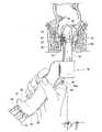
- FIG. 7is an anatomic view of the anal canal, with the treatment device shown in FIGS. 3 and 4 inserted for positioning relative to the dentate line and with the needle electrodes in their retracted position;
- FIG. 8is an anatomic view of the anal canal, with the treatment device shown in FIG. 7 with the needle electrodes in their extended position inside the internal sphincter muscle;
- FIG. 9is an anatomic view of the anal canal, with the treatment device shown in FIG. 8 , having been moved sequentially downward along the canal to form a first series of axially spaced lesion quadrants.
- FIG. 10is an anatomic view of the anal canal shown in FIG. 9 , with the treatment device shown in FIG. 9 rotated to a new position and the needle electrodes in their extended positions to form another series of axially spaced lesion quadrants rotationally spaced from the first series.
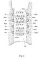
- FIG. 11is an anatomic view of a complex lesion pattern formed in the internal sphincter muscle by manipulating the device shown in FIGS. 3 and 4 in the manner shown in FIGS. 7 to 10 .
- FIG. 12shows a representative embodiment of a family of treatment devices for treating sphincters and adjoining tissue regions in the rectum and anal canal, the family comprising an assortment of barrels of different dimensions that are configured to adapt to the anatomic form and structure of different individuals in these tissue regions, the family also including instructions for use.
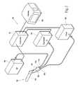
- FIG. 13shows a kit containing another representative embodiment of a family of treatment devices for treating sphincters and adjoining tissue regions in the rectum and anal canal, the family comprising a universal handle that couples to an assortment of barrels of different dimensions that are configured to adapt to the anatomic form and structure of different individuals in these tissue regions, the kit also containing instructions for use.
- FIG. 14shows another representative embodiment of a family of treatment devices for treating sphincters and adjoining tissue regions in the rectum and anal canal, the family comprising a universal handle with a composite barrel assembly that engages an assortment of canopy components of different dimensions that are configured to adapt to the anatomic form and structure of different individuals in these tissue regions.
- FIG. 15is a perspective view of the universal handle shown in FIG. 14 with a canopy component of a selected dimension engaged.
- FIG. 16is a kit containing the family of treatment devices shown in FIG. 14 , together with instructions for use.
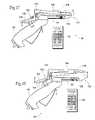
- FIGS. 17 and 18show a treatment device for treating sphincters and adjoining tissue regions in the rectum and anal canal, the treatment device comprising a variable speculum barrel assembly that is configured to adapt to the anatomic form and structure of different individuals in these tissue regions.
- This Specificationdiscloses various catheter-based systems and methods for treating dysfunction of sphincters and adjoining tissue regions in the body.
- the systems and methodsare particularly well suited for treating these dysfunctions in the lower gastrointestinal tract, e.g., in the intestines, rectum and anal canal. For this reason, the systems and methods will be described in this context.
- systems and methodsare applicable for use in treating other dysfunctions elsewhere in the body, e.g., for restoring compliance to or otherwise tightening interior tissue or muscle regions.
- the systems and methods that embody features of the inventionare also adaptable for use with systems and surgical techniques that are not necessarily catheter based.
- the rectumis the terminal part of the large intestine 12 .
- the rectum 10extends from the sigmoid flexure 14 (which is the narrowest part of the colon) to the anal orifice 16 .
- the rectum 10is about 15 to 17 cm in overall length.
- the upper or superior portion of the rectum 10extends downward from the sigmoid flexure 14 . This portion of the rectum 10 is almost completely surrounded by the peritoneum. A mucous membrane lines this portion of the rectum 10 . The mucous membrane is thicker, of a darker color, and more vascular than elsewhere in the colon.
- the superior portion of the rectum 10contains a number of permanent folds of a semi-lunar shape, which are called the Houston valves 18 . As FIG. 1 shows, there are usually three Houston valves 18 . Sometimes a fourth is present, and occasionally only two are found.
- the Houston valves 18overlap each other.
- the valves 18support the weight of fecal matter, to slow its descent toward the anal orifice 16 .
- the inferior or lower part of the rectum 10is contracted to expel fecal matter, a number of additional folds develop in the mucous membrane of the superior portion of the rectum 10 , to urge fecal matter downward.
- the middle portion of the rectum 10is covered anteriorly and laterally by peritoneum as it extends from the superior portion. However, as the rectum 10 extends further downward, the lateral peritoneum gradually recedes.
- the lower or inferior portion of the rectum 10is called the anal canal 20 . It typically extends about 4 to 5 cm above the anal orifice 16 .
- the anal canal 20is invested by the internal sphincter muscle 22 , supported by the Levatores ani muscle 24 , and surrounded at its termination by the external sphincter muscle 26 .
- the external sphincter muscle 26is a thin flat plane of muscular fibers, measuring about 5 cm in length. It is always in a state of tonic contraction to keep the anal orifice 16 closed. In an empty condition, the anal canal 20 therefore has the appearance of a longitudinal slit. The external sphincter muscle 26 can voluntarily be placed in a greater condition of contraction, to more firmly occlude the anal orifice 16 .
- the internal sphincter muscle 22is a muscular ring that surrounds the lower extremity of the rectum 10 for about 2 cm. Its inferior border is contiguous with the external sphincter muscle 26 . However, the functions of the two sphincter muscles 22 and 26 are separate. Unlike the external sphincter muscle 26 , the internal sphincter muscle 22 is an involuntary muscle. Together, the voluntary external sphincter muscle 26 works with the involuntary internal sphincter muscle 22 to occlude the anal orifice 16 . The internal sphincter muscle 22 contributes about 85% of the resting tone of the anal canal 20 , to keep fecal material in the rectum 10 until time of controlled expulsion.
- the levator ani muscle 24is a broad, thin muscle situated on each side of the pelvis. This muscle supports the lower end of the rectum 10 and bladder during the controlled efforts of expulsion.
- a pectinate (dentate) line 30is defined about 2.5 to 3 cm above the anal orifice 16 .
- the superior extent of the external sphincter muscle 26extends about 5 cm above the pectinate (dentate) line 30 .
- the superior extent of the internal sphincter muscle 22extends about 2 to 2.5 cm above the pectinate (dentate) line.
- Sensitive mucosal tissuelines the anal canal 20 below the pectinate line 30 .
- Anoderm tissueis sensitive to contact with fecal material. When contacting anoderm tissue, the sensed presence of fecal material excites a sensation demanding discharge.
- Mucosal tissue immediately above the pectinate line 30is also sensitive to the presence of fecal material.
- the anal columnsprovide sensory information that discriminates among different types and textures of fecal material, thereby aiding in overall control of the discharge of fecal material.
- treatment of the rectum 10should guard against damage to the mucosal tissue below and above the pectinate (dentate) line 30 .
- This sensitive mucosal tissuemay be damaged, e.g., by exposure to abnormal heat, and typically do not regenerate after thermal injury.
- the external sphincter muscle 26or the internal sphincter muscle 22 , or both lose their tone.
- the anal orifice 16is not occluded.
- Fecal materialdescends without control, to spontaneously excite the sensitive anoderm tissue to demand immediate discharge.
- FIG. 1the views of the rectum 10 and anal canal 20 shown in FIG. 1 , and elsewhere in the drawings, are not intended to be strictly accurate in an anatomic sense.
- the drawingsshow the rectum 10 and anal canal 20 in somewhat diagrammatic form to demonstrate the features of the invention.
- FIG. 2shows a system 34 for treating dysfunction of the external sphincter muscle 26 , or internal sphincter muscle 22 , or both.
- the system 34includes a treatment device 36 .
- the device 36can be constructed in various ways.
- the device 36includes a hand piece 38 made, e.g., from molded plastic.
- the hand piece 38includes a handle grip 40 , which is sized to be conveniently held by a physician, in the same fashion as, e.g., an anuscope.
- the handle grip 40carries a hollow, tubular barrel 42 , which projects outward from the grip 40 .
- the barrel 42terminates with a blunt, rounded distal end 44 .
- the barrel 42has an outside diameter that is sized and configured for insertion into the rectum 10 through the anal orifice 16 (see FIG. 7 ).
- the rounded distal end 44is configured to aid passage of the barrel 42 through the anal canal, without need for a separate introducer.
- the wall of the barrel 42is preferably made from a transparent, molded plastic material.
- the handle grip 40includes a viewing port 46 that allows a physician to look into the hollow interior of the barrel 42 .
- a light pipe 152stabilized by a bracket 154 within the barrel 42 (see FIGS. 5A and 5B ), can be coupled to a source of light to illuminate the distal end of the barrel 42 .
- the physicianmay also wear a head band with a light source. Looking through the viewing port 46 (see, e.g., FIG. 7 ), the physician can visualize surrounding tissue through the transparent wall of the barrel 42 to locate the barrel 42 at a desired depth of insertion into the rectum 10 , as will be described in greater detail later. Alternatively, the physician may look through the side of the barrel 42 at its proximal end to view tissue through the transparent wall of the barrel 42 at a more distal location.
- the barrel 42carries an array of needle electrodes 48 that can be selectively deployed into tissue surrounding the barrel 42 .
- the electrodes 48have sufficient distal sharpness and strength, when deployed, to penetrate a desired depth into the internal and/or external sphincter muscle 22 and/or 26 (see FIG. 8 ).
- the distal ends of the needle electrodes 48are desirably normally biased with an antegrade bend.
- the desired depth of penetrationcan range from about 7 mm to about 8 mm from the inside wall of the rectum 10 .
- ablation energycan be applied through the electrodes 48 to create one or more lesions, or a prescribed pattern of lesions, below the mucosal surface 76 of the rectum 10 .
- Natural healing of the subsurface lesions in the rectum 10can lead to a physical tightening and/or reduced compliance of the external or internal sphincter muscle 22 or 26 , or both muscles 22 and 26 .
- the physical tightening of one or both of these muscles 22 or 26can restore normal closure function, thereby providing therapy for fecal incontinence.
- the array of electrodes 48can be configured and mounted for deployment from the barrel 42 is various ways.
- the barrel 42includes an electrode carrier 50 .
- the carrier 50can comprise, e.g., a molded plastic part with a preformed pattern of recesses that define slots or channels 136 , as FIG. 6A also shows.
- the carrier 50can be mounted to the interior of the barrel 42 using, e.g., adhesive, or fasteners, or snap-fit or the heat-staked posts 73 , as FIGS. 6D and 6E best show.
- the array of needle electrodes 48are movably contained in certain of the channels 136 in the carrier 50 (see FIGS. 6D and 6E ).
- the needle electrodes 48are carried in the carrier 50 in a side-by-side relationship along an arcuate segment of the barrel 42 .
- the needle electrodes 48occupy an arc of about 67.5 degrees along the circumference of the barrel 42 .
- a finger-operated pull lever 52 on the handle gripserves to slide the needle electrodes 48 within the channels.
- an intermediate mechanical linkage 54couples the electrodes 48 as a group to the pull lever 52 .
- the mechanical linkage 54can include an adjustment mechanism 140 , comprising e.g., a screw, nut, and busing assembly, for adjusting the length of electrode extension during manufacturing.
- a torsion spring 56normally biases the pull lever 52 to maintain the needle electrodes 48 in their retracted position.
- Other spring or biasing mechanismscan be provided for the same purpose.
- a locking pawl 58 in the handle grip 40is biased by a spring 60 to swing into a detent 62 in the pull lever 52 as the pull lever 52 is depressed (as FIGS. 5A and 5B show). Within the detent 62 , the pawl 58 resists movement of the pull lever 52 out of the depressed position, thereby locking the needle electrodes 48 in their extended position.
- the locking pawl 58includes a release button 64 , which projects outside the back of handle grip 40 (i.e., on the side opposite to the pull lever 52 ). Thumb pressure on the button 64 overcomes the biasing force of the spring 60 and frees the pawl 58 from the detent 62 .
- the counter force of the spring 56serves to urge the pull lever 52 toward the neutral position, thereby moving the needle electrodes 48 back to their normally retracted positions.
- a fitting 66 on the handle grip 40is intended to be coupled to an external fluid delivery apparatus 68 (see FIG. 2 ).
- the apparatus 68conveys a cooling liquid into contact with mucosal tissue regions adjacent the electrodes 48 .
- the cooling fluidpreserves and protects the exterior muscosal tissue against damage while submucosal lesions are formed.
- tubing 70 contained within a channel in the carrier 50routes the cooling fluid to a fluid trough or manifold 72 formed in the carrier 50 distal to but near the termination of the channels 136 through which the electrodes 48 slide.
- a seal assembly 142(see FIGS. 6B and 6C ) is fitted, e.g., by adhesive or mechanical compression, over the fluid manifold 72 , as FIGS. 6D and 6E best show).
- the seal assembly 142can be made of various non-porous materials, e.g., silicone or thermoplastic elastomers.
- the silicone seal assembly 142includes an array of pre-formed bays 144 , equal in number to the number of electrodes 48 .
- Each bay 144includes a port 146 , which communicates with the fluid manifold 72 .
- An o-ring seal 148(see FIG. 6C ) on the back side of the seal assembly 142 desirably encircles the manifold 72 , to seal around the ports 146 .
- Irrigation fluid entering the manifold 72flows through the ports 146 into the bays 144 and thence into contact with tissue.
- the electrodes 48when extended, pierce the silicone material near each port 146 (see FIG. 6E ) within each bay 144 .
- the silicone materialacts as a septum, sealing about the electrodes 48 . In this way, irrigation fluid can be distributed in a reliable fashion near each electrode 48 .
- posts 150are pre-formed in the silicone seal assembly 142 near each port 146 .
- Thermocouples or other forms of temperature sensing devices 86are routed to each post 150 to provide the capability of sensing temperature near each electrode 48 .
- FIG. 2Another fitting 74 on the handle grip 40 is intended to be coupled to an external aspirating apparatus 76 (see FIG. 2 ).
- the apparatus 76aspirates liquid from the tissue region occupied by the barrel 42 .
- tubing 78 contained within a channel in the carrier 50extends into the distal end 44 of the barrel 42 , to communicate with an aspiration port 80 formed in the barrel 42 .
- Liquid external to the barrel 42is drawn through the port 80 into the tubing 78 by aspiration for discharge.
- Fittings 66 and 74are desirably spaced apart a sufficient distance to permit coupling to a syringe, so that positive or negative pressure can be applied to dislodge foreign matter.
- a connector 82 on the handle grip 40is intended to be coupled to an external generator 84 (see FIG. 2 ).
- the generator 84supplies treatment energy to the electrodes 48 .
- the generator 84supplies radio frequency energy, e.g., having a frequency in the range of about 400 kHz to about 10 mHz.
- the electrodes 48can be formed from various energy transmitting materials, e.g., nickel titanium, stainless steel, e.g., 304 stainless steel, or, a combination of nickel titanium and stainless steel.
- An electrical insulating materialis desirably coated about the needle electrodes 48 , except for a prescribed region of the distal ends, where radio frequency energy is applied to tissue.
- wiring channeled through the carrier 50couples the electrodes 48 to the connector 82 .
- Wiring routed through the carrier 50can also couple the connector 82 to the thermocouples or temperature sensing devices 86 carried within the posts 150 of the seal assembly 142 or on the electrodes 48 themselves.
- the system 34also includes a controller 32 .
- the controller 32which preferably includes a central processing unit (CPU), is linked to the generator 84 , the fluid delivery apparatus 68 , and the aspirating apparatus 76 .
- the controller 32governs the power levels, cycles, and duration that the radio frequency energy is distributed to the electrodes 48 , to achieve and maintain power levels appropriate to achieve the desired treatment objectives. In tandem, the controller 32 also governs the delivery of processing fluid and, if desired, the removal of aspirated material.
- the controller 32includes an input/output (I/O) device 88 .
- the I/O device 88allows the physician to input control and processing variables, to enable the controller to generate appropriate command signals.
- the I/O device 88also receives real time processing feedback information from the temperature sensors 86 associated with the operative element, for processing by the controller 32 , e.g., to govern the application of energy and the delivery of processing fluid.
- the I/O device 88can also include a graphical user interface (GUI), to graphically present processing information to the physician for viewing or analysis.
- GUIgraphical user interface
- the physiciangrasps the handle grip 40 and guides the barrel 42 into the anal canal 20 .
- the pull lever 52is in the neutral position and not depressed, so the needle electrodes 48 occupy their normal retracted position (as FIG. 7 shows).
- the physicianvisualizes the pectinate (dentate) line 30 through the barrel 42 .
- the physicianpositions the distal ends of the needle electrodes 48 at a desired location above the pectinate (dentate) line 30 .
- a light source or imaging apparatuscan also be inserted into the barrel 42 to provide local illumination, or the physician can wear a headlamp for this purpose.”
- the location of the distal ends of needle electrodes 48can also be marked by an opaque band 92 printed, scribed, or pasted on the outside of the barrel 42 .
- the band 92visually aids the physician in aligning the electrodes 48 at the desired tissue location with respect to the dentate line 30 .
- the physiciandepresses the pull lever 52 (see FIG. 8 ).
- the needle electrodes 48advance to and lock in their extended positions.
- the trigger lockis designed to provide an anti-tenting feature as well (the needles initially extend longer to poke through tenting tissue, then fall back to a slightly short treatment position).
- the distal ends of the electrodes 48pierce and pass through the mucosal tissue into the muscle tissue of the target sphincter muscle. In FIG. 8 , the distal end of the electrodes are shown penetrating the involuntary, internal sphincter muscle 22 .
- the physiciancommands the controller 32 to apply radio frequency energy through the needle electrodes 48 .
- the energycan be applied simultaneously by all electrodes 48 , or in any desired sequence.
- the energyohmically heats the muscle tissue.
- the controller 32samples temperatures sensed by the sensors 86 to control the application of energy, to achieve tissue temperatures in the targeted muscle tissue in the range of 551 C to 951 C.
- the fluid delivery apparatus 68conveys cooling fluid for discharge at the treatment site, to cool the mucosal surface while energy is being applied by the needle electrodes 48 .
- the aspirating apparatus 76draws aspirated material and the processing fluid through the tubing 78 for discharge.
- the array of needle electrodes 48creates a first pattern 94 of multiple lesions (see FIG. 11 ).
- the physicianactuates the button 64 to release the locking pawl 58 from the detent 62 .
- the pull lever 52returns to the spring-biased neutral position, thereby moving the needle electrodes 48 back to their retracted positions.
- the physicianmoves the barrel 42 axially downward to another location spaced from the first lesion pattern 94 .
- the subsidiary marker bands 156aid in positioning the barrel 42 .
- the physicianagain deploys the needle electrodes 48 and performs another lesion generating sequence (see FIG. 10 ).
- the physicianrepeats this sequence of steps until additional number of lesion patterns are formed within axially spaced quadrants ( FIG. 9 shows three additional patterns 96 , 98 , 100 )(also see FIG. 11 ).
- the physicianrotates the barrel 42 a selected arcuate distance at the level of the first lesion pattern 94 (see FIG. 10 ). For example, the physician can rotate the barrel 42 by forty-five degrees or by ninety degrees.
- the physicianagain deploys the needle electrodes 48 and performs another lesion generating sequence at the level of lesion pattern 94 (see FIG. 10 ).
- the physicianthen moves the barrel axially downward at a number of axially spaced levels generally aligned with lesion patterns 96 , 98 , and 100 .
- Second lesion pattern quadrants 94 ( 2 ), 96 ( 2 ), 98 ( 2 ), and 98 ( 2 )are created, circumferentially spaced from the first lesion pattern quadrants 94 , 96 , 98 , and 100 .
- the physiciancan repeat the above described sequence two additional times, rotating the barrel 42 at successive intervals and axially repositioning the barrel 42 to form third and fourth lesion pattern quadrants 94 ( 3 )- 100 ( 3 ) and 94 ( 4 )- 100 ( 4 ) (see FIG. 11 ).
- This protocolforms a composite lesion pattern 102 (see FIG. 11 ), which provides a density of lesions in the targeted sphincter tissue region to provoke a desired contraction of the sphincter tissue.
- the physicianmay decide to create the composite lesion pattern 102 in a different sequence.
- the physicianmay decide to form a given level of lesion pattern quadrants—e.g., 94 , 94 ( 1 ), 94 ( 3 ), and 94 ( 4 )—by maintaining the barrel 42 at the chosen level and rotating the barrel 42 at successive intervals, and then axially move downward to the next level and rotating the barrel 42 to form the next level of lesion pattern quadrants 96 , 96 ( 2 ), 96 ( 3 ), and 98 ( 3 ), and so on until the composite lesion pattern 102 us formed.
- the ultimate objectiveto provide a density of lesions in the targeted sphincter tissue region to provoke a desired contraction of the sphincter tissue—can be achieved in various alternative ways using the device 10 .
- the system 34desirably has the capability to accommodate the treatment of a population of different individuals, who present different anatomic forms and structures in the region of the rectum and/or anal orifice.
- Various illustrative embodimentsare shown, which provide treatment devices that can adapt to the anatomic form and structure of different individuals in these region.
- the system 34can include a family 106 of treatment devices 104 A, 104 B, and 104 C.
- Each treatment device 104 A, 104 B, and 104 Ccomprises a handle grip—respectively 40 A, 40 B, 40 C—and a barrel—respectively 42 A, 42 B, and 42 C—of the ensemble previously described.
- each barrel 42 A, 42 B, and 42 Chas a different dimension comprising an outside diameter and/or length, from smallest (barrel 42 A), intermediate outside (barrel 42 B), to largest (barrel 42 C).
- a representative range of barrel dimensionsis 20 mm (smallest), 30 mm (intermediate), and 40 mm (largest).
- the barrels 42 A, 42 B, and 42 Cmay have either a round or oval cross section and be marked with indicia indicating its diameter or relative size.
- the handle grip 40 A/ 40 B/ 40 C and respective barrel 42 A/ 42 B/ 42 Ccan be provided to form an assembled treatment device 104 A, 104 B, and 104 C (as FIG. 12 shows), intended for single use and subsequent disposal.
- the family 106can comprise a universal handle grip 40 U as a separate component intended for single use or for multiple uses.
- the family 106comprises an assortment of interchangeable barrels 42 A, 42 B, and 42 C of different dimensions.
- Each barrel 40 A, 40 B, and 40 Ccomprises a separate, disposable component, including the electrodes 48 and other associated components routed by a carrier 50 within a respective barrel.
- the physiciancan releasably connect a selected barrel 42 A, 42 B, or 42 C to the universal handle grip 40 U at time of use, to form the respective treatment device 104 A, 104 B, or 104 C.
- the selected barrelcan be disconnected from the universal handle grip 40 U and discarded.
- the entire formed treatment device 104 A, 104 B, or 104 Ccan be discarded after use.
- the system 34can provide the family 106 of treatment devices 104 A, 104 B, and 104 C as integrated devices (as FIG. 12 shows), individually prepackaged as single use items in a sterile fashion within peripherally sealed sheets of plastic film material that are torn or peeled away at the instance of use.
- the system 34can provide the family 106 as a kit 108 , with a universal handle grip 40 U accompanied by a selection of separate barrels 42 A, 42 B, and 42 C of different dimensions.
- the kit 106packages the handle grip 40 C and barrels 42 A, 42 B, and 42 C as single use items in a sterile fashion within peripherally sealed sheets of plastic film material that are torn or peeled away at the instance of use.
- the system 34can include, together with the particular treatment device or kit or separately supplied, instructions 138 for using the treatment device 104 A, 104 , 104 C.
- the instructions for usecan include the step of assessing the anatomic requirements of the individual to be treated, and selecting a barrel 42 A, 42 B, and 42 C from among the array of barrels to provide a treatment device based upon the assessed anatomic requirement.
- a treatment device 120can include a handle grip 40 with a composite barrel assembly 110 .
- the composite barrel assembly 110includes a frame component 112 and a canopy component 114 .
- the frame component 112is permanently coupled to the handle grip 40 .
- the frame component 112supports the carrier 50 and its components, which are secured within the frame component 112 in the same manner already described.
- the canopy component 114is not permanently coupled to the handle grip 40 . Instead, the canopy component 114 couples to the frame component 112 in a manner that allows the canopy component 114 to be inserted onto and released from the frame component 112 .
- the canopy component 114can rest on a slide-on track 116 for insertion and removal from the frame component 112 .
- the canopy component 114can include a snap-on/snap-off insertion/release that mates with a counterpart release mechanism on the frame component 112 .
- the outside diameter of the composite barrel assembly 110is determined by the dimensions of the frame component 112 , which are fixed, as well as the dimensions of the canopy component 114 , which can vary among an assortment of canopy components 114 .
- the system 34can include a family of 118 of canopy components 114 A, 114 B, 114 C each having a different dimension, from smallest (canopy component 114 A), intermediate (canopy component 114 B), to largest (canopy component 114 C).
- the dimensions of the particular canopy component 114 A, 114 B, or 114 C selected for coupling to the frame component 112dictates the overall final dimension of the composite barrel assembly 110 , from smallest, intermediate, to largest.
- the assembled frame/canopy unitmay have either a round or oval cross section. Generally, as smaller canopies are attached to a frame component having the same size, the assembled unit will have an increasingly oval cross section.
- the system 34can provide the treatment device 120 as a prepackaged handle grip 40 with preconnected frame component 112 , and a family 118 of separately prepackaged canopy components 114 A, 114 B, and 114 C of different dimensions, as FIG. 14 shows.
- the system 34can provide the treatment device 120 in a kit 108 , comprising a handle grip 40 with a preconnected frame component 112 , together with a family 118 of separate canopy components 114 A, 114 B, 114 C of different dimensions.
- the treatment device 120is intended to be a single use item which is discarded after use.
- the system 34can include, together with the particular treatment device 120 , or as separately supplied, instructions 138 for using the treatment device 120 .
- the instructions for usecan include the step of assessing the anatomic requirements of the individual to be treated, and selecting a canopy component 114 A, 114 B, and 114 C from among the family 118 of canopy components based upon the assessed anatomic requirements.
- a treatment device 122can comprise a handle grip 40 having a variable speculum barrel assembly 124 .
- the variable speculum barrel assembly 124includes upper and lower jaw components 126 and 128 .
- the lower jaw component 128is permanently coupled to the handle grip 40 .
- the lower jaw componentsupports the carrier 50 and its components, which are secured within the lower jaw component 128 in the same manner already described.
- the upper jaw component 126is pivotally connected to the handle grip 40 for articulation relative to the lower jaw component 128 .
- the upper jaw component 126includes a handle 130 that articulates the upper jaw component 126 about a pivot point mount 132 with respect to the lower jaw component 128 , which is fixed and coupled to the handle grip 40 .
- the maximum outside diameter of the barrel assembly 124is determined by degree of articulation of the upper jaw component 126 relative to the fixed lower jaw component 128 .
- the system 34can instantaneously provide a variable range of maximum outside diameters for the barrel assembly 124 , from smallest, intermediate, to largest.
- the pivot point mount 132can allow adjustment of the upper jaw component 126 in an up and down direction relative to the fixed lower jaw component 128 . In this way, the range of maximum outside diameters for the barrel assembly 124 is variable.
- a frictional latch mechanism 134can be provided to lock movement of the upper jaw component 126 when the articulation achieves a desired dimension.
- the treatment device 122can be packaged as a single use item in a sterile fashion within peripherally sealed sheets of plastic film material that are torn or peeled away at the instance of use.
- the system 34can include, together with the particular treatment device 122 or separately supplied, instructions 136 for using the device 122 .
- the instructions 136 for usecan include the step of assessing the anatomic requirements of the individual to be treated, and adjusting the articulation of the upper jaw component 126 based upon the assessed anatomic requirements.
Landscapes
- Health & Medical Sciences (AREA)
- Life Sciences & Earth Sciences (AREA)
- Surgery (AREA)
- Engineering & Computer Science (AREA)
- General Health & Medical Sciences (AREA)
- Veterinary Medicine (AREA)
- Public Health (AREA)
- Physics & Mathematics (AREA)
- Nuclear Medicine, Radiotherapy & Molecular Imaging (AREA)
- Animal Behavior & Ethology (AREA)
- Biomedical Technology (AREA)
- Heart & Thoracic Surgery (AREA)
- Medical Informatics (AREA)
- Molecular Biology (AREA)
- Biophysics (AREA)
- Radiology & Medical Imaging (AREA)
- Pathology (AREA)
- Optics & Photonics (AREA)
- Plasma & Fusion (AREA)
- Otolaryngology (AREA)
- Computer Networks & Wireless Communication (AREA)
- Surgical Instruments (AREA)
Abstract
Description
Claims (3)
Priority Applications (4)
| Application Number | Priority Date | Filing Date | Title |
|---|---|---|---|
| US10/911,395US7329254B2 (en) | 1998-02-19 | 2004-08-04 | Systems and methods for treating dysfunctions in the intestines and rectum that adapt to the anatomic form and structure of different individuals |
| US12/004,189US8696661B2 (en) | 1998-02-19 | 2007-12-20 | Systems and methods for treating dysfunctions in the intestines and rectum that adapt to the anatomic form and structure of different individuals |
| US14/214,880US9204926B2 (en) | 1998-02-19 | 2014-03-15 | Systems and methods for treating dysfunctions in the intestines and rectum that adapt to the anatomic form and structure of different individuals |
| US14/953,202US20160074109A1 (en) | 1998-02-19 | 2015-11-27 | Systems and methods for treating dysfunctions in the intestines and rectum that adapt to the anatomic form and structure of different individuals |
Applications Claiming Priority (5)
| Application Number | Priority Date | Filing Date | Title |
|---|---|---|---|
| US09/026,296US6009877A (en) | 1994-06-24 | 1998-02-19 | Method for treating a sphincter |
| US14374999P | 1999-07-14 | 1999-07-14 | |
| US09/556,169US6645201B1 (en) | 1998-02-19 | 2000-04-21 | Systems and methods for treating dysfunctions in the intestines and rectum |
| US10/674,242US7056320B2 (en) | 1999-07-14 | 2003-09-29 | Systems and methods for treating dysfunctions in the intestines and rectum |
| US10/911,395US7329254B2 (en) | 1998-02-19 | 2004-08-04 | Systems and methods for treating dysfunctions in the intestines and rectum that adapt to the anatomic form and structure of different individuals |
Related Parent Applications (1)
| Application Number | Title | Priority Date | Filing Date |
|---|---|---|---|
| US10/674,242Continuation-In-PartUS7056320B2 (en) | 1998-02-19 | 2003-09-29 | Systems and methods for treating dysfunctions in the intestines and rectum |
Related Child Applications (1)
| Application Number | Title | Priority Date | Filing Date |
|---|---|---|---|
| US12/004,189DivisionUS8696661B2 (en) | 1998-02-19 | 2007-12-20 | Systems and methods for treating dysfunctions in the intestines and rectum that adapt to the anatomic form and structure of different individuals |
Publications (2)
| Publication Number | Publication Date |
|---|---|
| US20050228371A1 US20050228371A1 (en) | 2005-10-13 |
| US7329254B2true US7329254B2 (en) | 2008-02-12 |
Family
ID=46302478
Family Applications (4)
| Application Number | Title | Priority Date | Filing Date |
|---|---|---|---|
| US10/911,395Expired - Fee RelatedUS7329254B2 (en) | 1998-02-19 | 2004-08-04 | Systems and methods for treating dysfunctions in the intestines and rectum that adapt to the anatomic form and structure of different individuals |
| US12/004,189Expired - Fee RelatedUS8696661B2 (en) | 1998-02-19 | 2007-12-20 | Systems and methods for treating dysfunctions in the intestines and rectum that adapt to the anatomic form and structure of different individuals |
| US14/214,880Expired - Fee RelatedUS9204926B2 (en) | 1998-02-19 | 2014-03-15 | Systems and methods for treating dysfunctions in the intestines and rectum that adapt to the anatomic form and structure of different individuals |
| US14/953,202AbandonedUS20160074109A1 (en) | 1998-02-19 | 2015-11-27 | Systems and methods for treating dysfunctions in the intestines and rectum that adapt to the anatomic form and structure of different individuals |
Family Applications After (3)
| Application Number | Title | Priority Date | Filing Date |
|---|---|---|---|
| US12/004,189Expired - Fee RelatedUS8696661B2 (en) | 1998-02-19 | 2007-12-20 | Systems and methods for treating dysfunctions in the intestines and rectum that adapt to the anatomic form and structure of different individuals |
| US14/214,880Expired - Fee RelatedUS9204926B2 (en) | 1998-02-19 | 2014-03-15 | Systems and methods for treating dysfunctions in the intestines and rectum that adapt to the anatomic form and structure of different individuals |
| US14/953,202AbandonedUS20160074109A1 (en) | 1998-02-19 | 2015-11-27 | Systems and methods for treating dysfunctions in the intestines and rectum that adapt to the anatomic form and structure of different individuals |
Country Status (1)
| Country | Link |
|---|---|
| US (4) | US7329254B2 (en) |
Cited By (27)
| Publication number | Priority date | Publication date | Assignee | Title |
|---|---|---|---|---|
| US20070100333A1 (en)* | 1999-11-16 | 2007-05-03 | Jerome Jackson | Methods and systems for determining physiologic characteristics for treatment of the esophagus |
| US20070118106A1 (en)* | 2005-11-23 | 2007-05-24 | Utley David S | Precision ablating method |
| US20070118104A1 (en)* | 2005-11-23 | 2007-05-24 | Wallace Michael P | Auto-aligning ablating device and method of use |
| US20070129720A1 (en)* | 2002-04-08 | 2007-06-07 | Ardian, Inc. | Methods and apparatus for performing a non-continuous circumferential treatment of a body lumen |
| US20080097427A1 (en)* | 2004-01-09 | 2008-04-24 | Barrx Medical, Inc. | Devices and Methods for Treatment of Luminal Tissue |
| US20080275445A1 (en)* | 2007-05-04 | 2008-11-06 | Barrx Medical, Inc. | Method and apparatus for gastrointestinal tract ablation for treatment of obesity |
| US20090012518A1 (en)* | 2007-07-06 | 2009-01-08 | Utley David S | Method and Apparatus for Ablation of Benign, Pre-Cancerous and Early Cancerous Lesions That Originate Within the Epithelium and are Limited to the Mucosal Layer of the Gastrointestinal Tract |
| US20090012513A1 (en)* | 2007-07-06 | 2009-01-08 | Utley David S | Ablation in the Gastrointestinal Tract to Achieve Hemostasis and Eradicate Lesions With a Propensity for Bleeding |
| US20090036886A1 (en)* | 2007-07-30 | 2009-02-05 | Utley David S | Cleaning device and methods |
| US20090036733A1 (en)* | 2007-07-30 | 2009-02-05 | Michael Wallace | Cleaning device and methods |
| US20090048593A1 (en)* | 1999-11-16 | 2009-02-19 | Ganz Robert A | System and method of treating abnormal tissue in the human esophagus |
| US20090318914A1 (en)* | 2008-06-18 | 2009-12-24 | Utley David S | System and method for ablational treatment of uterine cervical neoplasia |
| US20100049186A1 (en)* | 1997-08-13 | 2010-02-25 | Ams Research Corporation | Noninvasive devices, methods, and systems for shrinking of tissues |
| US20100063495A1 (en)* | 1996-10-11 | 2010-03-11 | Edwards Stuart D | System for tissue ablation |
| US20100114087A1 (en)* | 1998-02-19 | 2010-05-06 | Edwards Stuart D | Methods and devices for treating urinary incontinence |
| US20100191237A1 (en)* | 1998-05-20 | 2010-07-29 | Shadduck John H | Surgical instruments and techniques for treating gastro-esophageal reflux disease |
| US20100234840A1 (en)* | 1999-11-16 | 2010-09-16 | Jerome Jackson | Methods and systems for determining physiologic characteristics for treatment of the esophagus |
| US7959627B2 (en) | 2005-11-23 | 2011-06-14 | Barrx Medical, Inc. | Precision ablating device |
| US8177781B2 (en) | 2000-10-02 | 2012-05-15 | Novasys Medical, Inc. | Apparatus and methods for treating female urinary incontinence |
| US8251992B2 (en) | 2007-07-06 | 2012-08-28 | Tyco Healthcare Group Lp | Method and apparatus for gastrointestinal tract ablation to achieve loss of persistent and/or recurrent excess body weight following a weight-loss operation |
| US8403927B1 (en) | 2012-04-05 | 2013-03-26 | William Bruce Shingleton | Vasectomy devices and methods |
| US8784338B2 (en) | 2007-06-22 | 2014-07-22 | Covidien Lp | Electrical means to normalize ablational energy transmission to a luminal tissue surface of varying size |
| US9204921B2 (en) | 2012-12-13 | 2015-12-08 | Cook Medical Technologies Llc | RF energy controller and method for electrosurgical medical devices |
| US9364277B2 (en) | 2012-12-13 | 2016-06-14 | Cook Medical Technologies Llc | RF energy controller and method for electrosurgical medical devices |
| US9408662B2 (en) | 2012-05-07 | 2016-08-09 | Cook Medical Technologies Llc | Sphincterotome having expandable tines |
| US10278774B2 (en) | 2011-03-18 | 2019-05-07 | Covidien Lp | Selectively expandable operative element support structure and methods of use |
| US11246644B2 (en) | 2018-04-05 | 2022-02-15 | Covidien Lp | Surface ablation using bipolar RF electrode |
Families Citing this family (22)
| Publication number | Priority date | Publication date | Assignee | Title |
|---|---|---|---|---|
| US7329254B2 (en) | 1998-02-19 | 2008-02-12 | Curon Medical, Inc. | Systems and methods for treating dysfunctions in the intestines and rectum that adapt to the anatomic form and structure of different individuals |
| US8597290B2 (en)* | 1999-07-14 | 2013-12-03 | Mederi Therapeutics | Method for treating fecal incontinence |
| US8100822B2 (en) | 2004-03-16 | 2012-01-24 | Macroplata Systems, Llc | Anoscope for treating hemorrhoids without the trauma of cutting or the use of an endoscope |
| US20050288664A1 (en)* | 2004-06-21 | 2005-12-29 | Curon Medical, Inc. | Systems and methods for treating tissue regions of the body |
| US20070050001A1 (en)* | 2005-08-26 | 2007-03-01 | Solarant Medical, Inc. | Adjustable open loop control devices and methods |
| EP1897506B1 (en)* | 2006-09-08 | 2010-03-03 | Ethicon Endo-Surgery, Inc. | A surgical instrument for performing controlled myotomies |
| US8235983B2 (en) | 2007-07-12 | 2012-08-07 | Asthmatx, Inc. | Systems and methods for delivering energy to passageways in a patient |
| US8632458B2 (en) | 2011-10-26 | 2014-01-21 | Macroplata Inc. | Gentle hemorrhoid treatment offering a substantially painless healing |
| KR101605934B1 (en)* | 2010-04-26 | 2016-03-23 | 코비디엔 엘피 | Apparatus and method for effecting at least one anatomical structure |
| JP5200199B2 (en)* | 2011-03-28 | 2013-05-15 | オリンパスメディカルシステムズ株式会社 | Ultrasonic treatment device |
| US9814618B2 (en) | 2013-06-06 | 2017-11-14 | Boston Scientific Scimed, Inc. | Devices for delivering energy and related methods of use |
| EP3256797A1 (en)* | 2015-02-12 | 2017-12-20 | Carrier Corporation | Chiller for refrigeration system |
| US10856940B2 (en) | 2016-03-02 | 2020-12-08 | Covidien Lp | Ablation antenna including customizable reflectors |
| CN110381857B (en) | 2017-03-10 | 2023-02-10 | 波士顿科学医学有限公司 | Actuator Devices and Systems |
| MX2019010881A (en)* | 2017-03-17 | 2020-02-05 | Chaves De Oliveira Enio | Device, system and method for treating swollen vascular structures. |
| US11896823B2 (en) | 2017-04-04 | 2024-02-13 | Btl Healthcare Technologies A.S. | Method and device for pelvic floor tissue treatment |
| RU178741U1 (en)* | 2017-07-26 | 2018-04-18 | Федеральное государственное бюджетное образовательное учреждение высшего образования "Саратовский государственный технический университет имени Гагарина Ю.А." (СГТУ имени Гагарина Ю.А.) | Light guide adapter for proctologic mirror |
| US10857347B2 (en) | 2017-09-19 | 2020-12-08 | Pulse Biosciences, Inc. | Treatment instrument and high-voltage connectors for robotic surgical system |
| SE541467C2 (en)* | 2017-10-13 | 2019-10-08 | Dev Ab | Device for use in the treatment of hemorrhoids |
| EP3958773A1 (en)* | 2019-04-26 | 2022-03-02 | Hologic, Inc. | Systems and methods for therapy of pelvic conditions |
| US11517744B1 (en)* | 2020-03-23 | 2022-12-06 | Hemotec, LLC | Device for using electrotherapy for the relief of hemorrhoid inflammation |
| PL4039165T3 (en)* | 2021-02-04 | 2024-12-16 | Developeration Ab | PROCTOSCOPE |
Citations (20)
| Publication number | Priority date | Publication date | Assignee | Title |
|---|---|---|---|---|
| US2382109A (en) | 1943-08-06 | 1945-08-14 | William J Cameron | Diagnostic and electrosurgical appliance |
| US5370675A (en) | 1992-08-12 | 1994-12-06 | Vidamed, Inc. | Medical probe device and method |
| US5403311A (en) | 1993-03-29 | 1995-04-04 | Boston Scientific Corporation | Electro-coagulation and ablation and other electrotherapeutic treatments of body tissue |
| US5451223A (en) | 1983-03-14 | 1995-09-19 | Ben-Simhon; Haim | Electrosurgical instrument |
| US5582611A (en)* | 1992-05-19 | 1996-12-10 | Olympus Optical Co., Ltd. | Surgical device for stapling and/or fastening body tissues |
| US5709224A (en) | 1995-06-07 | 1998-01-20 | Radiotherapeutics Corporation | Method and device for permanent vessel occlusion |
| WO1998011834A1 (en) | 1996-09-20 | 1998-03-26 | Vidacare, Inc. | Ablation of rectal and other internal body structures |
| US5827276A (en) | 1995-03-24 | 1998-10-27 | Board Of Regents Of Univ Of Nebraksa | Apparatus for volumetric tissue ablation |
| US5849011A (en) | 1995-06-19 | 1998-12-15 | Vidamed, Inc. | Medical device with trigger actuation assembly |
| US5873877A (en) | 1997-04-11 | 1999-02-23 | Vidamed, Inc. | Medical probe device with transparent distal extremity |
| US6009877A (en) | 1994-06-24 | 2000-01-04 | Edwards; Stuart D. | Method for treating a sphincter |
| US6014589A (en) | 1997-11-12 | 2000-01-11 | Vnus Medical Technologies, Inc. | Catheter having expandable electrodes and adjustable stent |
| US6017338A (en) | 1993-12-21 | 2000-01-25 | Angeion Corporation | Fluid cooled and perfused tip for a catheter |
| US6056744A (en) | 1994-06-24 | 2000-05-02 | Conway Stuart Medical, Inc. | Sphincter treatment apparatus |
| US6092528A (en) | 1994-06-24 | 2000-07-25 | Edwards; Stuart D. | Method to treat esophageal sphincters |
| WO2000059393A1 (en) | 1999-04-02 | 2000-10-12 | Genesis Medical, Inc. | Treating body tissue by applying energy and substances |
| US6231571B1 (en) | 1999-05-03 | 2001-05-15 | Alan G. Ellman | Electrosurgical handpiece for treating tissue |
| US6325798B1 (en) | 1998-02-19 | 2001-12-04 | Curon Medical, Inc. | Vacuum-assisted systems and methods for treating sphincters and adjoining tissue regions |
| US6419673B1 (en)* | 1996-05-06 | 2002-07-16 | Stuart Edwards | Ablation of rectal and other internal body structures |
| US6645201B1 (en)* | 1998-02-19 | 2003-11-11 | Curon Medical, Inc. | Systems and methods for treating dysfunctions in the intestines and rectum |
Family Cites Families (30)
| Publication number | Priority date | Publication date | Assignee | Title |
|---|---|---|---|---|
| US2482971A (en)* | 1947-07-11 | 1949-09-27 | Golson Kelly Kendall | Self-illuminated transparent proctoscope |
| US3747603A (en)* | 1971-11-03 | 1973-07-24 | B Adler | Cervical dilators |
| US5385544A (en) | 1992-08-12 | 1995-01-31 | Vidamed, Inc. | BPH ablation method and apparatus |
| US5435805A (en)* | 1992-08-12 | 1995-07-25 | Vidamed, Inc. | Medical probe device with optical viewing capability |
| US4813422A (en) | 1987-03-06 | 1989-03-21 | Healthcare Technological Resources, Inc. | Bowel control probe and method for controlling bowel incontinence |
| US5391144A (en)* | 1990-02-02 | 1995-02-21 | Olympus Optical Co., Ltd. | Ultrasonic treatment apparatus |
| US5452719A (en) | 1991-07-23 | 1995-09-26 | Eisman; Eugene | Multiple electrode myographic probe and method |
| US5259388A (en) | 1991-07-23 | 1993-11-09 | Eugene Eisman | Multiple electrode myographic probe |
| US5542916A (en) | 1992-08-12 | 1996-08-06 | Vidamed, Inc. | Dual-channel RF power delivery system |
| US6051017A (en) | 1996-02-20 | 2000-04-18 | Advanced Bionics Corporation | Implantable microstimulator and systems employing the same |
| US7022105B1 (en) | 1996-05-06 | 2006-04-04 | Novasys Medical Inc. | Treatment of tissue in sphincters, sinuses and orifices |
| US6743197B1 (en) | 1996-07-10 | 2004-06-01 | Novasys Medical, Inc. | Treatment of discrete tissues in respiratory, urinary, circulatory, reproductive and digestive systems |
| US6480746B1 (en)* | 1997-08-13 | 2002-11-12 | Surx, Inc. | Noninvasive devices, methods, and systems for shrinking of tissues |
| US6159170A (en) | 1997-03-13 | 2000-12-12 | Borodulin; German | Universal mechanical dilator combined with massaging action |
| US5871481A (en)* | 1997-04-11 | 1999-02-16 | Vidamed, Inc. | Tissue ablation apparatus and method |
| US5964756A (en)* | 1997-04-11 | 1999-10-12 | Vidamed, Inc. | Transurethral needle ablation device with replaceable stylet cartridge |
| US7329254B2 (en) | 1998-02-19 | 2008-02-12 | Curon Medical, Inc. | Systems and methods for treating dysfunctions in the intestines and rectum that adapt to the anatomic form and structure of different individuals |
| US6258087B1 (en) | 1998-02-19 | 2001-07-10 | Curon Medical, Inc. | Expandable electrode assemblies for forming lesions to treat dysfunction in sphincters and adjoining tissue regions |
| US6355031B1 (en) | 1998-02-19 | 2002-03-12 | Curon Medical, Inc. | Control systems for multiple electrode arrays to create lesions in tissue regions at or near a sphincter |
| US6402744B2 (en) | 1998-02-19 | 2002-06-11 | Curon Medical, Inc. | Systems and methods for forming composite lesions to treat dysfunction in sphincters and adjoining tissue regions |
| US6066096A (en)* | 1998-05-08 | 2000-05-23 | Duke University | Imaging probes and catheters for volumetric intraluminal ultrasound imaging and related systems |
| US6802841B2 (en) | 1998-06-04 | 2004-10-12 | Curon Medical, Inc. | Systems and methods for applying a selected treatment agent into contact with tissue to treat sphincter dysfunction |
| BR9911634A (en) | 1998-06-29 | 2001-10-02 | Procter & Gamble | Disposable article to be adapted to a user with an external anal sphincter muscle |
| US6156032A (en) | 1998-09-30 | 2000-12-05 | Scimed Life Systems, Inc. | Method for causing a stricture of a body passageway |
| WO2000066017A1 (en) | 1999-05-04 | 2000-11-09 | Curon Medical, Inc. | Electrodes for creating lesions in tissue regions at or near a sphincter |
| WO2001017452A1 (en) | 1999-09-08 | 2001-03-15 | Curon Medical, Inc. | System for controlling a family of treatment devices |
| AU7352500A (en) | 1999-09-08 | 2001-04-10 | Curon Medical, Inc. | Systems and methods for monitoring and controlling use of medical devices |
| US7160294B2 (en) | 2003-09-02 | 2007-01-09 | Curon Medical, Inc. | Systems and methods for treating hemorrhoids |
| US20060089636A1 (en) | 2004-10-27 | 2006-04-27 | Christopherson Mark A | Ultrasound visualization for transurethral needle ablation |
| JP5764564B2 (en) | 2009-09-22 | 2015-08-19 | メデリ セラピューティクス インコーポレイテッド | Systems and methods for controlling the use and operation of various therapeutic device groups |
- 2004
- 2004-08-04USUS10/911,395patent/US7329254B2/ennot_activeExpired - Fee Related
- 2007
- 2007-12-20USUS12/004,189patent/US8696661B2/ennot_activeExpired - Fee Related
- 2014
- 2014-03-15USUS14/214,880patent/US9204926B2/ennot_activeExpired - Fee Related
- 2015
- 2015-11-27USUS14/953,202patent/US20160074109A1/ennot_activeAbandoned
Patent Citations (22)
| Publication number | Priority date | Publication date | Assignee | Title |
|---|---|---|---|---|
| US2382109A (en) | 1943-08-06 | 1945-08-14 | William J Cameron | Diagnostic and electrosurgical appliance |
| US5451223A (en) | 1983-03-14 | 1995-09-19 | Ben-Simhon; Haim | Electrosurgical instrument |
| US5451223B1 (en) | 1983-03-14 | 1998-11-03 | Ben Simhon Haim | Electrosurgical instrument |
| US5582611A (en)* | 1992-05-19 | 1996-12-10 | Olympus Optical Co., Ltd. | Surgical device for stapling and/or fastening body tissues |
| US5370675A (en) | 1992-08-12 | 1994-12-06 | Vidamed, Inc. | Medical probe device and method |
| US5403311A (en) | 1993-03-29 | 1995-04-04 | Boston Scientific Corporation | Electro-coagulation and ablation and other electrotherapeutic treatments of body tissue |
| US6017338A (en) | 1993-12-21 | 2000-01-25 | Angeion Corporation | Fluid cooled and perfused tip for a catheter |
| US6009877A (en) | 1994-06-24 | 2000-01-04 | Edwards; Stuart D. | Method for treating a sphincter |
| US6092528A (en) | 1994-06-24 | 2000-07-25 | Edwards; Stuart D. | Method to treat esophageal sphincters |
| US6056744A (en) | 1994-06-24 | 2000-05-02 | Conway Stuart Medical, Inc. | Sphincter treatment apparatus |
| US5827276A (en) | 1995-03-24 | 1998-10-27 | Board Of Regents Of Univ Of Nebraksa | Apparatus for volumetric tissue ablation |
| US5709224A (en) | 1995-06-07 | 1998-01-20 | Radiotherapeutics Corporation | Method and device for permanent vessel occlusion |
| US5849011A (en) | 1995-06-19 | 1998-12-15 | Vidamed, Inc. | Medical device with trigger actuation assembly |
| US6419673B1 (en)* | 1996-05-06 | 2002-07-16 | Stuart Edwards | Ablation of rectal and other internal body structures |
| WO1998011834A1 (en) | 1996-09-20 | 1998-03-26 | Vidacare, Inc. | Ablation of rectal and other internal body structures |
| US5873877A (en) | 1997-04-11 | 1999-02-23 | Vidamed, Inc. | Medical probe device with transparent distal extremity |
| US6014589A (en) | 1997-11-12 | 2000-01-11 | Vnus Medical Technologies, Inc. | Catheter having expandable electrodes and adjustable stent |
| US6325798B1 (en) | 1998-02-19 | 2001-12-04 | Curon Medical, Inc. | Vacuum-assisted systems and methods for treating sphincters and adjoining tissue regions |
| US6645201B1 (en)* | 1998-02-19 | 2003-11-11 | Curon Medical, Inc. | Systems and methods for treating dysfunctions in the intestines and rectum |
| WO2000059393A1 (en) | 1999-04-02 | 2000-10-12 | Genesis Medical, Inc. | Treating body tissue by applying energy and substances |
| US6231571B1 (en) | 1999-05-03 | 2001-05-15 | Alan G. Ellman | Electrosurgical handpiece for treating tissue |
| US7056320B2 (en)* | 1999-07-14 | 2006-06-06 | Curon Medical, Inc. | Systems and methods for treating dysfunctions in the intestines and rectum |
Cited By (59)
| Publication number | Priority date | Publication date | Assignee | Title |
|---|---|---|---|---|
| US20100063495A1 (en)* | 1996-10-11 | 2010-03-11 | Edwards Stuart D | System for tissue ablation |
| US20100049186A1 (en)* | 1997-08-13 | 2010-02-25 | Ams Research Corporation | Noninvasive devices, methods, and systems for shrinking of tissues |
| US9023031B2 (en) | 1997-08-13 | 2015-05-05 | Verathon Inc. | Noninvasive devices, methods, and systems for modifying tissues |
| US20100114087A1 (en)* | 1998-02-19 | 2010-05-06 | Edwards Stuart D | Methods and devices for treating urinary incontinence |
| US20100191237A1 (en)* | 1998-05-20 | 2010-07-29 | Shadduck John H | Surgical instruments and techniques for treating gastro-esophageal reflux disease |
| US8012149B2 (en) | 1999-11-16 | 2011-09-06 | Barrx Medical, Inc. | Methods and systems for determining physiologic characteristics for treatment of the esophagus |
| US20070100333A1 (en)* | 1999-11-16 | 2007-05-03 | Jerome Jackson | Methods and systems for determining physiologic characteristics for treatment of the esophagus |
| US9039699B2 (en) | 1999-11-16 | 2015-05-26 | Covidien Lp | Methods and systems for treatment of tissue in a body lumen |
| US7993336B2 (en) | 1999-11-16 | 2011-08-09 | Barrx Medical, Inc. | Methods and systems for determining physiologic characteristics for treatment of the esophagus |
| US8876818B2 (en) | 1999-11-16 | 2014-11-04 | Covidien Lp | Methods and systems for determining physiologic characteristics for treatment of the esophagus |
| US20090048593A1 (en)* | 1999-11-16 | 2009-02-19 | Ganz Robert A | System and method of treating abnormal tissue in the human esophagus |
| US9597147B2 (en) | 1999-11-16 | 2017-03-21 | Covidien Lp | Methods and systems for treatment of tissue in a body lumen |
| US20100234840A1 (en)* | 1999-11-16 | 2010-09-16 | Jerome Jackson | Methods and systems for determining physiologic characteristics for treatment of the esophagus |
| US9555222B2 (en) | 1999-11-16 | 2017-01-31 | Covidien Lp | Methods and systems for determining physiologic characteristics for treatment of the esophagus |
| US8398631B2 (en) | 1999-11-16 | 2013-03-19 | Covidien Lp | System and method of treating abnormal tissue in the human esophagus |
| US8377055B2 (en) | 1999-11-16 | 2013-02-19 | Covidien Lp | Methods and systems for determining physiologic characteristics for treatment of the esophagus |
| US8177781B2 (en) | 2000-10-02 | 2012-05-15 | Novasys Medical, Inc. | Apparatus and methods for treating female urinary incontinence |
| US8465482B2 (en) | 2000-10-02 | 2013-06-18 | Verathon, Inc. | Apparatus and methods for treating female urinary incontinence |
| US8968284B2 (en) | 2000-10-02 | 2015-03-03 | Verathon Inc. | Apparatus and methods for treating female urinary incontinence |
| US20070129720A1 (en)* | 2002-04-08 | 2007-06-07 | Ardian, Inc. | Methods and apparatus for performing a non-continuous circumferential treatment of a body lumen |
| US8347891B2 (en)* | 2002-04-08 | 2013-01-08 | Medtronic Ardian Luxembourg S.A.R.L. | Methods and apparatus for performing a non-continuous circumferential treatment of a body lumen |
| US10856939B2 (en) | 2004-01-09 | 2020-12-08 | Covidien Lp | Devices and methods for treatment of luminal tissue |
| US10278776B2 (en) | 2004-01-09 | 2019-05-07 | Covidien Lp | Devices and methods for treatment of luminal tissue |
| US8192426B2 (en) | 2004-01-09 | 2012-06-05 | Tyco Healthcare Group Lp | Devices and methods for treatment of luminal tissue |
| US9393069B2 (en) | 2004-01-09 | 2016-07-19 | Covidien Lp | Devices and methods for treatment of luminal tissue |
| US20080097427A1 (en)* | 2004-01-09 | 2008-04-24 | Barrx Medical, Inc. | Devices and Methods for Treatment of Luminal Tissue |
| US9918794B2 (en) | 2005-11-23 | 2018-03-20 | Covidien Lp | Auto-aligning ablating device and method of use |
| US20070118104A1 (en)* | 2005-11-23 | 2007-05-24 | Wallace Michael P | Auto-aligning ablating device and method of use |
| US7959627B2 (en) | 2005-11-23 | 2011-06-14 | Barrx Medical, Inc. | Precision ablating device |
| US9179970B2 (en) | 2005-11-23 | 2015-11-10 | Covidien Lp | Precision ablating method |
| US20070118106A1 (en)* | 2005-11-23 | 2007-05-24 | Utley David S | Precision ablating method |
| US7997278B2 (en) | 2005-11-23 | 2011-08-16 | Barrx Medical, Inc. | Precision ablating method |
| US9918793B2 (en) | 2005-11-23 | 2018-03-20 | Covidien Lp | Auto-aligning ablating device and method of use |
| US8702695B2 (en) | 2005-11-23 | 2014-04-22 | Covidien Lp | Auto-aligning ablating device and method of use |
| US8702694B2 (en) | 2005-11-23 | 2014-04-22 | Covidien Lp | Auto-aligning ablating device and method of use |
| US9993281B2 (en) | 2007-05-04 | 2018-06-12 | Covidien Lp | Method and apparatus for gastrointestinal tract ablation for treatment of obesity |
| US8641711B2 (en) | 2007-05-04 | 2014-02-04 | Covidien Lp | Method and apparatus for gastrointestinal tract ablation for treatment of obesity |
| US20080275445A1 (en)* | 2007-05-04 | 2008-11-06 | Barrx Medical, Inc. | Method and apparatus for gastrointestinal tract ablation for treatment of obesity |
| US8784338B2 (en) | 2007-06-22 | 2014-07-22 | Covidien Lp | Electrical means to normalize ablational energy transmission to a luminal tissue surface of varying size |
| US9198713B2 (en) | 2007-06-22 | 2015-12-01 | Covidien Lp | Electrical means to normalize ablational energy transmission to a luminal tissue surface of varying size |
| US10575902B2 (en) | 2007-06-22 | 2020-03-03 | Covidien Lp | Electrical means to normalize ablational energy transmission to a luminal tissue surface of varying size |
| US8439908B2 (en) | 2007-07-06 | 2013-05-14 | Covidien Lp | Ablation in the gastrointestinal tract to achieve hemostasis and eradicate lesions with a propensity for bleeding |
| US9839466B2 (en) | 2007-07-06 | 2017-12-12 | Covidien Lp | Method and apparatus for gastrointestinal tract ablation to achieve loss of persistent and/or recurrent excess body weight following a weight loss operation |
| US20090012518A1 (en)* | 2007-07-06 | 2009-01-08 | Utley David S | Method and Apparatus for Ablation of Benign, Pre-Cancerous and Early Cancerous Lesions That Originate Within the Epithelium and are Limited to the Mucosal Layer of the Gastrointestinal Tract |
| US9364283B2 (en) | 2007-07-06 | 2016-06-14 | Covidien Lp | Method and apparatus for gastrointestinal tract ablation to achieve loss of persistent and/or recurrent excess body weight following a weight loss operation |
| US20090012513A1 (en)* | 2007-07-06 | 2009-01-08 | Utley David S | Ablation in the Gastrointestinal Tract to Achieve Hemostasis and Eradicate Lesions With a Propensity for Bleeding |
| US8251992B2 (en) | 2007-07-06 | 2012-08-28 | Tyco Healthcare Group Lp | Method and apparatus for gastrointestinal tract ablation to achieve loss of persistent and/or recurrent excess body weight following a weight-loss operation |
| US8646460B2 (en) | 2007-07-30 | 2014-02-11 | Covidien Lp | Cleaning device and methods |
| US8273012B2 (en) | 2007-07-30 | 2012-09-25 | Tyco Healthcare Group, Lp | Cleaning device and methods |
| US20090036733A1 (en)* | 2007-07-30 | 2009-02-05 | Michael Wallace | Cleaning device and methods |
| US20090036886A1 (en)* | 2007-07-30 | 2009-02-05 | Utley David S | Cleaning device and methods |
| US9314289B2 (en) | 2007-07-30 | 2016-04-19 | Covidien Lp | Cleaning device and methods |
| US20090318914A1 (en)* | 2008-06-18 | 2009-12-24 | Utley David S | System and method for ablational treatment of uterine cervical neoplasia |
| US10278774B2 (en) | 2011-03-18 | 2019-05-07 | Covidien Lp | Selectively expandable operative element support structure and methods of use |
| US8403927B1 (en) | 2012-04-05 | 2013-03-26 | William Bruce Shingleton | Vasectomy devices and methods |
| US9408662B2 (en) | 2012-05-07 | 2016-08-09 | Cook Medical Technologies Llc | Sphincterotome having expandable tines |
| US9204921B2 (en) | 2012-12-13 | 2015-12-08 | Cook Medical Technologies Llc | RF energy controller and method for electrosurgical medical devices |
| US9364277B2 (en) | 2012-12-13 | 2016-06-14 | Cook Medical Technologies Llc | RF energy controller and method for electrosurgical medical devices |
| US11246644B2 (en) | 2018-04-05 | 2022-02-15 | Covidien Lp | Surface ablation using bipolar RF electrode |
Also Published As
| Publication number | Publication date |
|---|---|
| US8696661B2 (en) | 2014-04-15 |
| US9204926B2 (en) | 2015-12-08 |
| US20080103498A1 (en) | 2008-05-01 |
| US20140200403A1 (en) | 2014-07-17 |
| US20050228371A1 (en) | 2005-10-13 |
| US20160074109A1 (en) | 2016-03-17 |
Similar Documents
| Publication | Publication Date | Title |
|---|---|---|
| US7329254B2 (en) | Systems and methods for treating dysfunctions in the intestines and rectum that adapt to the anatomic form and structure of different individuals | |
| US7056320B2 (en) | Systems and methods for treating dysfunctions in the intestines and rectum | |
| US9125665B2 (en) | Method for treating fecal incontinence | |
| JP5764564B2 (en) | Systems and methods for controlling the use and operation of various therapeutic device groups | |
| CN102821710B (en) | Systems and methods for prostate treatment | |
| US6544226B1 (en) | Operative devices that can be removably fitted on catheter bodies to treat tissue regions in the body | |
| JP2002542891A (en) | Integrated tissue heating and cooling device | |
| WO2010008807A1 (en) | Devices and methods for treatment of hollow organs | |
| WO2011005897A2 (en) | Apparatus for treating medical conditions of hollow anatomical structures | |
| WO2011005902A2 (en) | Apparatus for treating medical conditions of hollow anatomical structures |
Legal Events
| Date | Code | Title | Description |
|---|---|---|---|
| AS | Assignment | Owner name:CURON MEDICAL, INC., CALIFORNIA Free format text:ASSIGNMENT OF ASSIGNORS INTEREST;ASSIGNORS:WEST, SCOTT;GAISER, JOHN W.;RIMROTH, PATRICK;AND OTHERS;REEL/FRAME:016417/0166;SIGNING DATES FROM 20050308 TO 20050320 | |
| STCF | Information on status: patent grant | Free format text:PATENTED CASE | |
| AS | Assignment | Owner name:RESPIRATORY DIAGNOSTIC, INC., WASHINGTON Free format text:ASSIGNMENT OF ASSIGNORS INTEREST;ASSIGNOR:CURON MEDICAL, INC. BY JOHN T. KENDALL, TRUSTEE;REEL/FRAME:022034/0702 Effective date:20070413 Owner name:RESPIRATORY DIAGNOSTIC, INC.,WASHINGTON Free format text:ASSIGNMENT OF ASSIGNORS INTEREST;ASSIGNOR:CURON MEDICAL, INC. BY JOHN T. KENDALL, TRUSTEE;REEL/FRAME:022034/0702 Effective date:20070413 | |
| AS | Assignment | Owner name:MEDERI THERAPEUTICS, INC., CONNECTICUT Free format text:ASSIGNMENT OF ASSIGNORS INTEREST;ASSIGNOR:RESPIRATORY DIAGNOSTIC, INC.;REEL/FRAME:022597/0080 Effective date:20080912 | |
| FEPP | Fee payment procedure | Free format text:PAT HOLDER CLAIMS SMALL ENTITY STATUS, ENTITY STATUS SET TO SMALL (ORIGINAL EVENT CODE: LTOS); ENTITY STATUS OF PATENT OWNER: LARGE ENTITY | |
| REFU | Refund | Free format text:REFUND - PAYMENT OF MAINTENANCE FEE, 4TH YEAR, LARGE ENTITY (ORIGINAL EVENT CODE: R1551); ENTITY STATUS OF PATENT OWNER: LARGE ENTITY | |
| FPAY | Fee payment | Year of fee payment:4 | |
| FEPP | Fee payment procedure | Free format text:PAT HOLDER NO LONGER CLAIMS SMALL ENTITY STATUS, ENTITY STATUS SET TO UNDISCOUNTED (ORIGINAL EVENT CODE: STOL); ENTITY STATUS OF PATENT OWNER: LARGE ENTITY | |
| REFU | Refund | Free format text:REFUND - PAYMENT OF MAINTENANCE FEE, 8TH YR, SMALL ENTITY (ORIGINAL EVENT CODE: R2552); ENTITY STATUS OF PATENT OWNER: LARGE ENTITY | |
| FPAY | Fee payment | Year of fee payment:8 | |
| AS | Assignment | Owner name:HORIZON CREDIT II LLC, CONNECTICUT Free format text:SECURITY INTEREST;ASSIGNOR:MEDERI THERAPEUTICS INC.;REEL/FRAME:036252/0728 Effective date:20150730 | |
| AS | Assignment | Owner name:MEDERI RF, LLC, TEXAS Free format text:ASSIGNMENT OF ASSIGNORS INTEREST;ASSIGNOR:HORIZON CREDIT II LLC;REEL/FRAME:046069/0567 Effective date:20180424 Owner name:HORIZON CREDIT II LLC, CONNECTICUT Free format text:ASSIGNMENT OF ASSIGNORS INTEREST;ASSIGNOR:MEDERI THERAPEUTICS INC.;REEL/FRAME:046076/0317 Effective date:20180424 | |
| FEPP | Fee payment procedure | Free format text:MAINTENANCE FEE REMINDER MAILED (ORIGINAL EVENT CODE: REM.); ENTITY STATUS OF PATENT OWNER: LARGE ENTITY | |
| LAPS | Lapse for failure to pay maintenance fees | Free format text:PATENT EXPIRED FOR FAILURE TO PAY MAINTENANCE FEES (ORIGINAL EVENT CODE: EXP.); ENTITY STATUS OF PATENT OWNER: LARGE ENTITY | |
| STCH | Information on status: patent discontinuation | Free format text:PATENT EXPIRED DUE TO NONPAYMENT OF MAINTENANCE FEES UNDER 37 CFR 1.362 | |
| FP | Lapsed due to failure to pay maintenance fee | Effective date:20200212 |