US7329234B2 - Self-occluding catheter - Google Patents
Self-occluding catheterDownload PDFInfo
- Publication number
- US7329234B2 US7329234B2US09/764,659US76465901AUS7329234B2US 7329234 B2US7329234 B2US 7329234B2US 76465901 AUS76465901 AUS 76465901AUS 7329234 B2US7329234 B2US 7329234B2
- Authority
- US
- United States
- Prior art keywords
- spool
- inlet
- self
- occluding
- end portions
- Prior art date
- Legal status (The legal status is an assumption and is not a legal conclusion. Google has not performed a legal analysis and makes no representation as to the accuracy of the status listed.)
- Expired - Lifetime, expires
Links
Images


Classifications
- A—HUMAN NECESSITIES
- A61—MEDICAL OR VETERINARY SCIENCE; HYGIENE
- A61M—DEVICES FOR INTRODUCING MEDIA INTO, OR ONTO, THE BODY; DEVICES FOR TRANSDUCING BODY MEDIA OR FOR TAKING MEDIA FROM THE BODY; DEVICES FOR PRODUCING OR ENDING SLEEP OR STUPOR
- A61M1/00—Suction or pumping devices for medical purposes; Devices for carrying-off, for treatment of, or for carrying-over, body-liquids; Drainage systems
- A61M1/36—Other treatment of blood in a by-pass of the natural circulatory system, e.g. temperature adaptation, irradiation ; Extra-corporeal blood circuits
- A61M1/3621—Extra-corporeal blood circuits
- A61M1/367—Circuit parts not covered by the preceding subgroups of group A61M1/3621
- A—HUMAN NECESSITIES
- A61—MEDICAL OR VETERINARY SCIENCE; HYGIENE
- A61M—DEVICES FOR INTRODUCING MEDIA INTO, OR ONTO, THE BODY; DEVICES FOR TRANSDUCING BODY MEDIA OR FOR TAKING MEDIA FROM THE BODY; DEVICES FOR PRODUCING OR ENDING SLEEP OR STUPOR
- A61M1/00—Suction or pumping devices for medical purposes; Devices for carrying-off, for treatment of, or for carrying-over, body-liquids; Drainage systems
- A61M1/36—Other treatment of blood in a by-pass of the natural circulatory system, e.g. temperature adaptation, irradiation ; Extra-corporeal blood circuits
- A61M1/3621—Extra-corporeal blood circuits
- A61M1/3653—Interfaces between patient blood circulation and extra-corporal blood circuit
- A61M1/3659—Cannulae pertaining to extracorporeal circulation
- A61M1/3661—Cannulae pertaining to extracorporeal circulation for haemodialysis
- A—HUMAN NECESSITIES
- A61—MEDICAL OR VETERINARY SCIENCE; HYGIENE
- A61M—DEVICES FOR INTRODUCING MEDIA INTO, OR ONTO, THE BODY; DEVICES FOR TRANSDUCING BODY MEDIA OR FOR TAKING MEDIA FROM THE BODY; DEVICES FOR PRODUCING OR ENDING SLEEP OR STUPOR
- A61M25/00—Catheters; Hollow probes
- A61M25/0021—Catheters; Hollow probes characterised by the form of the tubing
- A61M25/0023—Catheters; Hollow probes characterised by the form of the tubing by the form of the lumen, e.g. cross-section, variable diameter
- A61M25/0026—Multi-lumen catheters with stationary elements
- A61M25/0028—Multi-lumen catheters with stationary elements characterized by features relating to at least one lumen located at the proximal part of the catheter, e.g. alterations in lumen shape or valves
- A—HUMAN NECESSITIES
- A61—MEDICAL OR VETERINARY SCIENCE; HYGIENE
- A61M—DEVICES FOR INTRODUCING MEDIA INTO, OR ONTO, THE BODY; DEVICES FOR TRANSDUCING BODY MEDIA OR FOR TAKING MEDIA FROM THE BODY; DEVICES FOR PRODUCING OR ENDING SLEEP OR STUPOR
- A61M25/00—Catheters; Hollow probes
- A61M25/0097—Catheters; Hollow probes characterised by the hub
- A—HUMAN NECESSITIES
- A61—MEDICAL OR VETERINARY SCIENCE; HYGIENE
- A61M—DEVICES FOR INTRODUCING MEDIA INTO, OR ONTO, THE BODY; DEVICES FOR TRANSDUCING BODY MEDIA OR FOR TAKING MEDIA FROM THE BODY; DEVICES FOR PRODUCING OR ENDING SLEEP OR STUPOR
- A61M25/00—Catheters; Hollow probes
- A61M25/10—Balloon catheters
- A61M25/1018—Balloon inflating or inflation-control devices
- A61M25/10184—Means for controlling or monitoring inflation or deflation
- A61M25/10185—Valves
- A—HUMAN NECESSITIES
- A61—MEDICAL OR VETERINARY SCIENCE; HYGIENE
- A61M—DEVICES FOR INTRODUCING MEDIA INTO, OR ONTO, THE BODY; DEVICES FOR TRANSDUCING BODY MEDIA OR FOR TAKING MEDIA FROM THE BODY; DEVICES FOR PRODUCING OR ENDING SLEEP OR STUPOR
- A61M25/00—Catheters; Hollow probes
- A61M25/10—Balloon catheters
- A61M25/1025—Connections between catheter tubes and inflation tubes
- A—HUMAN NECESSITIES
- A61—MEDICAL OR VETERINARY SCIENCE; HYGIENE
- A61M—DEVICES FOR INTRODUCING MEDIA INTO, OR ONTO, THE BODY; DEVICES FOR TRANSDUCING BODY MEDIA OR FOR TAKING MEDIA FROM THE BODY; DEVICES FOR PRODUCING OR ENDING SLEEP OR STUPOR
- A61M39/00—Tubes, tube connectors, tube couplings, valves, access sites or the like, specially adapted for medical use
- A61M39/22—Valves or arrangement of valves
- A61M39/223—Multiway valves
- A—HUMAN NECESSITIES
- A61—MEDICAL OR VETERINARY SCIENCE; HYGIENE
- A61M—DEVICES FOR INTRODUCING MEDIA INTO, OR ONTO, THE BODY; DEVICES FOR TRANSDUCING BODY MEDIA OR FOR TAKING MEDIA FROM THE BODY; DEVICES FOR PRODUCING OR ENDING SLEEP OR STUPOR
- A61M39/00—Tubes, tube connectors, tube couplings, valves, access sites or the like, specially adapted for medical use
- A61M39/22—Valves or arrangement of valves
- A61M39/24—Check- or non-return valves
- A—HUMAN NECESSITIES
- A61—MEDICAL OR VETERINARY SCIENCE; HYGIENE
- A61M—DEVICES FOR INTRODUCING MEDIA INTO, OR ONTO, THE BODY; DEVICES FOR TRANSDUCING BODY MEDIA OR FOR TAKING MEDIA FROM THE BODY; DEVICES FOR PRODUCING OR ENDING SLEEP OR STUPOR
- A61M39/00—Tubes, tube connectors, tube couplings, valves, access sites or the like, specially adapted for medical use
- A61M39/22—Valves or arrangement of valves
- A61M39/26—Valves closing automatically on disconnecting the line and opening on reconnection thereof
- A—HUMAN NECESSITIES
- A61—MEDICAL OR VETERINARY SCIENCE; HYGIENE
- A61M—DEVICES FOR INTRODUCING MEDIA INTO, OR ONTO, THE BODY; DEVICES FOR TRANSDUCING BODY MEDIA OR FOR TAKING MEDIA FROM THE BODY; DEVICES FOR PRODUCING OR ENDING SLEEP OR STUPOR
- A61M5/00—Devices for bringing media into the body in a subcutaneous, intra-vascular or intramuscular way; Accessories therefor, e.g. filling or cleaning devices, arm-rests
- A61M5/14—Infusion devices, e.g. infusing by gravity; Blood infusion; Accessories therefor
- A61M5/158—Needles for infusions; Accessories therefor, e.g. for inserting infusion needles, or for holding them on the body
- A61M5/1582—Double lumen needles
- A—HUMAN NECESSITIES
- A61—MEDICAL OR VETERINARY SCIENCE; HYGIENE
- A61M—DEVICES FOR INTRODUCING MEDIA INTO, OR ONTO, THE BODY; DEVICES FOR TRANSDUCING BODY MEDIA OR FOR TAKING MEDIA FROM THE BODY; DEVICES FOR PRODUCING OR ENDING SLEEP OR STUPOR
- A61M25/00—Catheters; Hollow probes
- A61M2025/0018—Catheters; Hollow probes having a plug, e.g. an inflatable plug for closing catheter lumens
- A—HUMAN NECESSITIES
- A61—MEDICAL OR VETERINARY SCIENCE; HYGIENE
- A61M—DEVICES FOR INTRODUCING MEDIA INTO, OR ONTO, THE BODY; DEVICES FOR TRANSDUCING BODY MEDIA OR FOR TAKING MEDIA FROM THE BODY; DEVICES FOR PRODUCING OR ENDING SLEEP OR STUPOR
- A61M25/00—Catheters; Hollow probes
- A61M25/0021—Catheters; Hollow probes characterised by the form of the tubing
- A61M25/0023—Catheters; Hollow probes characterised by the form of the tubing by the form of the lumen, e.g. cross-section, variable diameter
- A61M25/0026—Multi-lumen catheters with stationary elements
- A61M25/003—Multi-lumen catheters with stationary elements characterized by features relating to least one lumen located at the distal part of the catheter, e.g. filters, plugs or valves
- A61M2025/0031—Multi-lumen catheters with stationary elements characterized by features relating to least one lumen located at the distal part of the catheter, e.g. filters, plugs or valves characterized by lumina for withdrawing or delivering, i.e. used for extracorporeal circuit treatment
- A—HUMAN NECESSITIES
- A61—MEDICAL OR VETERINARY SCIENCE; HYGIENE
- A61M—DEVICES FOR INTRODUCING MEDIA INTO, OR ONTO, THE BODY; DEVICES FOR TRANSDUCING BODY MEDIA OR FOR TAKING MEDIA FROM THE BODY; DEVICES FOR PRODUCING OR ENDING SLEEP OR STUPOR
- A61M39/00—Tubes, tube connectors, tube couplings, valves, access sites or the like, specially adapted for medical use
- A61M39/22—Valves or arrangement of valves
- A61M39/24—Check- or non-return valves
- A61M2039/2473—Valve comprising a non-deformable, movable element, e.g. ball-valve, valve with movable stopper or reciprocating element
- A61M2039/2486—Guided stem, e.g. reciprocating stopper
- A—HUMAN NECESSITIES
- A61—MEDICAL OR VETERINARY SCIENCE; HYGIENE
- A61M—DEVICES FOR INTRODUCING MEDIA INTO, OR ONTO, THE BODY; DEVICES FOR TRANSDUCING BODY MEDIA OR FOR TAKING MEDIA FROM THE BODY; DEVICES FOR PRODUCING OR ENDING SLEEP OR STUPOR
- A61M2205/00—General characteristics of the apparatus
- A61M2205/82—Internal energy supply devices
- A61M2205/8275—Mechanical
- A61M2205/8287—Mechanical operated by an external magnetic or electromagnetic field
- Y—GENERAL TAGGING OF NEW TECHNOLOGICAL DEVELOPMENTS; GENERAL TAGGING OF CROSS-SECTIONAL TECHNOLOGIES SPANNING OVER SEVERAL SECTIONS OF THE IPC; TECHNICAL SUBJECTS COVERED BY FORMER USPC CROSS-REFERENCE ART COLLECTIONS [XRACs] AND DIGESTS
- Y10—TECHNICAL SUBJECTS COVERED BY FORMER USPC
- Y10T—TECHNICAL SUBJECTS COVERED BY FORMER US CLASSIFICATION
- Y10T137/00—Fluid handling
- Y10T137/8593—Systems
- Y10T137/877—With flow control means for branched passages
- Y10T137/87708—With common valve operator
- Y10T137/8778—Spring biased
Definitions
- the present inventionrelates generally to catheters for use in medical applications such as hemodialysis wherein fluids are withdrawn and/or introduced into a cavity of the body.
- the inventionrelates particularly to a hemodialysis catheter having internal means to automatically stop blood flow after a dialysis procedure has been conducted.
- Hemodialysisis a process of mass transfer in which certain chemical substances accumulated in the blood because of kidney failure are transferred from the blood across a semipermeable membrane to a balanced salt solution in a dialysis machine.
- a double-lumen catheteris utilized to simultaneously withdraw blood from a body cavity through one channel or lumen for processing in a dialysis machine and to reintroduce the processed blood back to the patient through a separate lumen.
- Such catheterstypically include a catheter hub or branch connector for connecting the catheter to tubes leading to and from a dialysis unit.
- the hub or connectormay also be adapted for accommodating injection syringes, or other extracorporeal equipment which may be required for a selected medical procedure.
- the hubtypically includes extension tubes which accommodate clamps for opening and closing the fluid passage ways of the respective extension tubes. The clamps serve as on-off valves for controlling the flow of blood between the catheter and dialysis unit or other medical equipment.
- Typical dialysis cathetersare shown in U.S. Pat. No. 5,197,951 and U.S. Pat. No. 5,486,159 both to Mahurkar.
- a self-occluding cathetergenerally includes a body portion for connection to extracorporeal equipment and an elongated tubular portion for insertion into a body cavity.
- the elongated tubular portionmay be fixed to or made removable from the body portion.
- the tubular portionincludes at least one lumen which is in fluid communication with at least one internal fluid conduit of the body portion.
- the body portionalso includes an internal transverse bore which is in fluid communication with the internal fluid conduits of the body portion. Supported within the transverse bore is a spool which is slidable between an open and a closed position.
- a biasing deviceis provided adjacent the spool for resiliently urging the spool to a normally closed position wherein the spool blocks the internal fluid conduits thereby preventing fluid flow through the body portion.
- the spoolslides to an open position thereby permitting fluid flow through the body portion.
- the biasing devicereturns the spool to its closed position whereby the internal fluid conduits are again blocked.
- the biasing devicepreferably comprises one or more magnets fixed within the body portion which generate a magnetic force for urging a magnetically polarized spool to its closed position.
- one or more magnetsare integrally molded within the spool to provide the magnetic charge to the spool.
- the spoolis preferably in the form of a cylindrical member having two opposite end portions, a shoulder portion positioned between the end portions and a reduced diameter neck portion positioned between each of the end portions and the shoulder portion. The shoulder portion slides in close fitting relationship with the transverse bore and is acted upon by the positive or negative fluid pressure applied to the equipment connection end to move the spool to its open position. In the spool's closed position, the end portions block both an inlet and an outlet fluid conduit of the body to prevent fluid flow through the body.
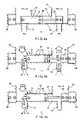
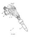
- FIG. 1is a perspective, partial cross-sectional, view of the preferred embodiment of the self-occluding catheter formed in accordance with the present invention.
- FIGS. 2 a , 2 b and 2 care schematic drawings illustrating the operation of the catheter shown in FIG. 1 .
- FIG. 3is a perspective, partial cross-sectional, view of an alternate embodiment of the self-occluding catheter formed in accordance with the present invention.
- FIGS. 4 a , 4 b and 4 care schematic drawings illustrating the operation of the catheter shown in FIG. 3 .
- FIG. 5is a perspective, partial cross-sectional, view of another alternate embodiment of the self-occluding catheter formed in accordance with the present invention.
- FIGS. 6 a , 6 b and 6 care schematic drawings illustrating the operation of the catheter shown in FIG. 5 .
- FIG. 1a preferred embodiment of the self-occluding catheter formed in accordance with the present invention is shown.
- the catheter shown in FIG. 1is a double-lumen catheter adapted for hemodialysis procedures, however, the present invention may be utilized in single-lumen catheters, as discussed below, or in multiple-lumen catheters which may be adapted for any other of a variety of medical procedures.
- the preferred form of the self-occluding catheter 10generally includes a body portion 11 , having a generally triangular cross-sectional configuration defining a wide proximal end 12 , and a narrow distal end 13 .
- An elongated flexible tubular extension 14is connected to the distal end 13 of the body portion.
- proximal and distalare used to denote opposite ends of body portion 11 .
- the distal end 13 of the body portionis provided with an external thread 15 which engages with a cooperating threaded connector 16 of the tubular extension 14 so that the tubular extension may be removed and replaced with other tubular portions or with other catheters.
- the body portion 11alone may take the form of a catheter connector for connecting conventional catheters to extracorporeal medical equipment.
- the body portion 11 and the tubular portion 12may be molded together as a unitary catheter as shown in FIG. 3 .
- the tubular portion 14must be flexible to allow for insertion into a body cavity.
- the body portion 11 and the tubular portion 14may be molded or extruded of any known biocompatible polymeric material. Silicone is a preferred material for these applications because it is inert and is tolerated by the human body for long periods of time without reaction.
- the body portion 11includes an inlet fluid conduit 17 , an outlet fluid conduit 18 , a transverse bore 19 , an inlet port 20 and an outlet port 21 formed therein to be in fluid communication.
- the inlet and outlet fluid conduits 17 and 18extend from the distal end 13 of the body 11 and intersect with the transverse bore 19 .
- the inlet and outlet ports 20 and 21extend from the proximal end 12 of the body and intersect with the transverse bore 19 adjacent respective inlet and outlet fluid conduits 17 and 18 .
- the inlet and outlet fluid conduit 17 and 18are also in fluid communication with respective inlet and outlet lumens (not shown) of the tubular extension 14 when the tubular portion is connected to the body 11 .
- the conduits 17 and 18 , the bore 19 and the ports 20 and 21may be formed by conventional machining techniques, e.g. drilling, reaming etc,. or may be internally molded within the body portion.
- the inlet and outlet ports 20 and 21are provided with external threads 22 at the proximal end 12 of the body portion 11 which cooperate with threaded connectors supplied on conventional tubing of extracorporeal equipment such as a hemodialysis unit (not shown).
- the inlet and outlet fluid conduits and portsare formed in the shape of a “V” as shown in FIG. 1 , however any spatial configuration may be utilized.
- the transverse bore 19is in fluid communication with the inlet and outlet fluid conduits 17 and 18 and the inlet and outlet ports 20 and 21 .
- a spool 23which may be formed of a similar biocompatible material as the body 11 and tubular extension 14 .
- the spool 23is an elongate member formed with opposite end portions 24 and 25 , a central shoulder portion 26 spaced between the end portions and a neck portion 27 positioned between and joining each end portion 24 and 25 and the shoulder portion 26 .
- the spool 23is generally cylindrical with the shoulder portion 26 having a diameter approximately equal to but slightly less than the diameter of the transverse bore 19 so that the shoulder portion 26 is positioned in close sliding relationship within the transverse bore.
- the diameter of the end portions 24 and 25is preferably equal to the diameter of the shoulder portion 26 and the diameter of the neck portion 27 is smaller than the diameters of both the end portions and the shoulder portion.
- the length of the end portionsis such that when the spool 23 is centrally positioned within the transverse bore 19 of the body portion 11 the end portions completely close or occlude the inlet and outlet fluid conduits 17 and 18 .
- the shoulder portion 26includes a fluid sealing ring 28 to prevent fluid flow therepast and between the inlet and outlet fluid conduits 17 and 18 .
- the fluid sealing ring 28 shown in FIGS. 1-6comprises an annular groove formed on the shoulder portion 26 which is fitted with an O-ring, however, other seals such as a flaring-pressure seal, a lip seal or a ball bearing seal may be utilized.
- the spool 23is resiliently urged into its central closed position, (in which the inlet and outlet fluid conduits 17 and 18 are occluded), by a biasing device.
- the biasing devicecomprises two external magnets 29 , fixed in opposite ends of the transverse bore 19 , which generate a magnetic force upon a magnetically charged or polarized spool 23 .
- the spoolis magnetically charged by providing internal magnets 30 within end portion 24 and 25 .
- internal magnets 30are integrally molded into the end portions 24 and 25 to provide the magnetic polarization to the spool 23 .
- the polarities of the internal magnets 30 and the external magnets 29are positioned such that the magnets generate a magnetic force which urges and maintains the spool 23 in a central closed position within the transverse bore 19 between the two opposite external magnets 29 .
- FIG. 1its operation may be schematically described with respect to FIGS. 2 a , 2 b and 2 c.
- FIG. 2 ashows the location of the spool 23 in its normally closed central position wherein the end portions 24 and 25 occlude the inlet and outlet fluid conduits 17 and 18 .
- the normally closed positionis maintained by the respective polarities of magnets 29 and 30 as indicated in FIGS. 2 a - 2 c .
- Thisis the position of the spool when injection caps (not shown) are in place on the threaded port connectors 22 prior to connecting the catheter 10 to a dialysis unit.
- the tubular extension 14 of the double-lumen catheter 10is introduced in the direction of blood flow within a large vein in a conventional manner.
- the injection capsare removed and the inlet and outlet ports 20 and 21 of the proximal end 12 of the body 11 are connected to conventional tubes of a dialysis unit.
- the inlet and outlet pressures, P 1 and P 4Prior to connection to the dialysis unit, the inlet and outlet pressures, P 1 and P 4 , at the inlet and outlet ports 20 and 21 , respectively, are essentially zero.
- the venous pressures, P 2 and P 3applied to the inlet and outlet fluid conduits 17 and 18 , respectively, by the bloodstream flowing through the vein are relatively low as compared to the magnetic force generated by the internal and external magnets 30 and 29 . Therefore, the spool 23 stays in its central closed position in which the inlet and outlet fluid conduits 17 and 18 are occluded by the end portions 24 and 25 of the spool, thereby preventing blood flow from the vein or air flow into the vein.
- the dialysis unitsimultaneously applies a positive injection fluid pressure +P 1 at the inlet port 20 and a negative aspiration fluid pressure ⁇ P 4 at the outlet port 21 .
- the positive injection pressure +P 1 applied at the inlet port 20acts upon both the inlet end portion 24 and the shoulder portion 26 of the spool 23 overcoming the magnetic force applied by magnets 29 and 30 to move the spool in the direction of the applied pressure +P 1 (i.e., to the right as shown in FIG. 2 b ) and against the magnetic force so that the inlet end portion 24 slides away from the inlet fluid conduit 17 .
- the negative aspiration pressure ⁇ P 4 applied at the outlet port 21simultaneously acts upon both the outlet end portion 25 and the shoulder portion 26 to move the spool 23 against the magnetic force and in the direction of the applied pressure ⁇ P 4 until the outlet fluid conduit 18 is no longer blocked by the outlet end portion 25 .
- the end portions 24 and 25no longer occluding the inlet and outlet fluid conduits 17 and 18 , blood may flow to and from the dialysis unit through the body portion 11 .
- the inlet and outlet pressures P 1 and P 4 applied to the inlet and outlet ports 20 and 21return to zero and the magnetic force of the magnets 29 and 30 returns the spool 23 to its central closed position wherein the inlet and outlet conduits 17 and 18 are again blocked as shown in FIG. 2 a.
- the operation described aboverelates specifically to a hemodialysis procedure in which the catheter is connected to a dialysis unit.
- the self-occluding catheter of the present inventionmay be utilized in a variety of other typical medical procedures.
- a syringemay be inserted in either the inlet or outlet port 20 or 21 and a negative aspiration pressure may be applied with the syringe as shown in FIG. 2 c .
- the spool 23moves in response to the negative fluid pressure, as described above, to unblock the respective fluid conduit so that blood may flow around the neck portion 27 of the spool.
- a positive fluid pressuresuch as applied when administering a medication with a syringe, may be applied alone to either port thereby moving the spool against the magnetic force to open the inlet conduit as described above. Accordingly, the self-occluding catheter of the present invention is not limited to hemodialysis procedures.
- FIG. 3shows an alternate embodiment of the present invention in which the tubular extension 14 is formed together with the body portion 11 as a unitary catheter.
- FIG. 3also illustrates an alternate embodiment of the spool 31 comprising two opposite end portions 32 and 33 and a single central neck portion 34 .
- the end portions 32 and 33have a diameter approximately equal to but slightly less than the diameter of the transverse bore 19 such that the end portions fit in close sliding relationship within the transverse bore.
- the end portion 32 adjacent the inlet fluid conduit 17also includes an annular groove for receiving a respective sealing ring 28 .
- the spool 31 of FIG. 3is magnetically charged (i.e.
- the entire spool 31is positively or negatively magnetically charged.
- the oppositely disposed external magnets 29are positioned within the transverse bore 19 such that their polarities generate a magnetic force urging the spool into a central closed position in which the end portions 32 and 33 occlude the inlet and outlet fluid conduits 17 and 18 as illustrated in FIGS. 3 and 4 a.
- FIG. 5shows another alternate embodiment of the present invention in which a single-lumen catheter 40 and an alternate biasing device is utilized.
- the body portion 41includes only one internal fluid conduit 42 and port 43 which is in fluid communication with a single lumen (not shown) of the tubular portion 44 .
- the single-lumen catheter 40 of FIG. 5may be utilized in such typical medical procedures as drawing blood and administering medication.
- the single lumen catheter 40 of FIG. 5is shown to be essentially one-half of the catheter 10 shown in FIG. 1 . Other configurations of single lumen catheter 40 are within the contemplation of the present invention.
- the spool 45 of FIG. 5is similar to the spool 31 shown in FIG. 3 in that it includes two opposite end portions 46 and 47 in close sliding relationship with the transverse bore 19 and a reduced diameter central neck portion 48 . In the present embodiment, however, the sealing ring 28 is fixed on the end portion 47 opposite the conduit blocking end portion 46 .
- the spool 45may be molded with internal magnets 30 in both end portions 46 and 47 which are magnetically urged by two external magnets 29 fixed at opposite ends of the transverse bore 19 , as described above. Alternatively, a spring 49 may take the place of one or both of the external magnets 29 for urging the spool 45 to its central closed position.
- FIGS. 6 a , 6 b and 6 cillustrate the operation of the single-lumen catheter 40 .
- the magnets and/or springsurge the spool 45 to its normally closed position wherein the conduit blocking end portion 46 occludes the internal fluid conduit 42 of the body.
- a positive injection pressure +P 1is applied to the connection port 43 , the fluid pressure acts upon both end portions 46 and 47 urging the spool 45 to the right as shown in FIG. 6 b wherein the conduit blocking end portion 46 is moved out of the way of the internal conduit 42 , thereby allowing fluid flow from the proximal end to the distal end of the catheter.
- Vents 50are provided through the body portion 41 to vent the volume within the chamber 51 surrounding the spring 49 so that the spool 45 may move within the transverse bore.
- a negative aspiration pressure ⁇ P 1is applied to the connection port 43 , the escaping fluid pressure draws both end portions 46 and 47 of the spool 45 to the left wherein the internal fluid conduit 42 is again opened and fluid may flow from the distal end of the catheter to the proximal end of the catheter around the neck portion 48 of the spool.
- any combination of the above embodimentsmay be utilized in the present invention without taking away from the scope of the invention. What is provided as a result is a reduced size, light-weight catheter which reduces the discomfort to the patient and requires less manipulation by the medical professional to complete a given medical procedure. Notably, there are no requirements for extension tubes or clamps at the connection ports to stop blood flow after the procedure has been conducted.
- the deviceis also tamper resistant and is less prone to inadvertent manipulation.
- the devicemay be designed to be a unitary catheter or may be a catheter connector in which any desired catheter tube may be selected and connected to the body portion.
Landscapes
- Health & Medical Sciences (AREA)
- Heart & Thoracic Surgery (AREA)
- Life Sciences & Earth Sciences (AREA)
- General Health & Medical Sciences (AREA)
- Veterinary Medicine (AREA)
- Anesthesiology (AREA)
- Biomedical Technology (AREA)
- Hematology (AREA)
- Engineering & Computer Science (AREA)
- Animal Behavior & Ethology (AREA)
- Public Health (AREA)
- Pulmonology (AREA)
- Vascular Medicine (AREA)
- Biophysics (AREA)
- Cardiology (AREA)
- Child & Adolescent Psychology (AREA)
- Urology & Nephrology (AREA)
- External Artificial Organs (AREA)
- Infusion, Injection, And Reservoir Apparatuses (AREA)
- Media Introduction/Drainage Providing Device (AREA)
Abstract
Description
Claims (10)
Priority Applications (2)
| Application Number | Priority Date | Filing Date | Title |
|---|---|---|---|
| US09/764,659US7329234B2 (en) | 1999-08-05 | 2001-01-17 | Self-occluding catheter |
| US12/029,807US7766859B2 (en) | 1999-08-05 | 2008-02-12 | Self-occluding catheter |
Applications Claiming Priority (2)
| Application Number | Priority Date | Filing Date | Title |
|---|---|---|---|
| US09/368,611US6179806B1 (en) | 1999-08-05 | 1999-08-05 | Self-occluding catheter |
| US09/764,659US7329234B2 (en) | 1999-08-05 | 2001-01-17 | Self-occluding catheter |
Related Parent Applications (1)
| Application Number | Title | Priority Date | Filing Date |
|---|---|---|---|
| US09/368,611ContinuationUS6179806B1 (en) | 1999-08-05 | 1999-08-05 | Self-occluding catheter |
Related Child Applications (1)
| Application Number | Title | Priority Date | Filing Date |
|---|---|---|---|
| US12/029,807ContinuationUS7766859B2 (en) | 1999-08-05 | 2008-02-12 | Self-occluding catheter |
Publications (2)
| Publication Number | Publication Date |
|---|---|
| US20010041857A1 US20010041857A1 (en) | 2001-11-15 |
| US7329234B2true US7329234B2 (en) | 2008-02-12 |
Family
ID=23451970
Family Applications (3)
| Application Number | Title | Priority Date | Filing Date |
|---|---|---|---|
| US09/368,611Expired - LifetimeUS6179806B1 (en) | 1999-08-05 | 1999-08-05 | Self-occluding catheter |
| US09/764,659Expired - LifetimeUS7329234B2 (en) | 1999-08-05 | 2001-01-17 | Self-occluding catheter |
| US12/029,807Expired - Fee RelatedUS7766859B2 (en) | 1999-08-05 | 2008-02-12 | Self-occluding catheter |
Family Applications Before (1)
| Application Number | Title | Priority Date | Filing Date |
|---|---|---|---|
| US09/368,611Expired - LifetimeUS6179806B1 (en) | 1999-08-05 | 1999-08-05 | Self-occluding catheter |
Family Applications After (1)
| Application Number | Title | Priority Date | Filing Date |
|---|---|---|---|
| US12/029,807Expired - Fee RelatedUS7766859B2 (en) | 1999-08-05 | 2008-02-12 | Self-occluding catheter |
Country Status (7)
| Country | Link |
|---|---|
| US (3) | US6179806B1 (en) |
| EP (1) | EP1200145B1 (en) |
| JP (1) | JP4297639B2 (en) |
| AU (1) | AU6376300A (en) |
| CA (1) | CA2378339C (en) |
| DE (1) | DE60031124T2 (en) |
| WO (1) | WO2001010485A1 (en) |
Cited By (37)
| Publication number | Priority date | Publication date | Assignee | Title |
|---|---|---|---|---|
| US20080132829A1 (en)* | 1999-08-05 | 2008-06-05 | Sansoucy Michael R | Self-Occluding Catheter |
| US20080197024A1 (en)* | 2003-12-05 | 2008-08-21 | Dexcom, Inc. | Analyte sensor |
| US20080306435A1 (en)* | 2007-06-08 | 2008-12-11 | Dexcom, Inc. | Integrated medicament delivery device for use with continuous analyte sensor |
| US20090124964A1 (en)* | 2003-12-05 | 2009-05-14 | Dexcom, Inc. | Integrated device for continuous in vivo analyte detection and simultaneous control of an infusion device |
| US20090131768A1 (en)* | 2006-10-04 | 2009-05-21 | Dexcom, Inc. | Analyte sensor |
| US20090131777A1 (en)* | 2006-10-04 | 2009-05-21 | Dexcom, Inc. | Analyte sensor |
| US20090131769A1 (en)* | 2006-10-04 | 2009-05-21 | Dexcom, Inc. | Analyte sensor |
| US20090131776A1 (en)* | 2006-10-04 | 2009-05-21 | Dexcom, Inc. | Analyte sensor |
| US20090137887A1 (en)* | 2006-10-04 | 2009-05-28 | Dexcom, Inc. | Analyte sensor |
| US20090178459A1 (en)* | 2003-08-01 | 2009-07-16 | Dexcom, Inc. | Analyte sensor |
| US20090182217A1 (en)* | 2003-12-05 | 2009-07-16 | Dexcom, Inc. | Analyte sensor |
| US7613491B2 (en) | 2002-05-22 | 2009-11-03 | Dexcom, Inc. | Silicone based membranes for use in implantable glucose sensors |
| US7615007B2 (en) | 2006-10-04 | 2009-11-10 | Dexcom, Inc. | Analyte sensor |
| US7640048B2 (en) | 2004-07-13 | 2009-12-29 | Dexcom, Inc. | Analyte sensor |
| US7783333B2 (en) | 2004-07-13 | 2010-08-24 | Dexcom, Inc. | Transcutaneous medical device with variable stiffness |
| US7885697B2 (en) | 2004-07-13 | 2011-02-08 | Dexcom, Inc. | Transcutaneous analyte sensor |
| US8364231B2 (en) | 2006-10-04 | 2013-01-29 | Dexcom, Inc. | Analyte sensor |
| US8364230B2 (en) | 2006-10-04 | 2013-01-29 | Dexcom, Inc. | Analyte sensor |
| US8364229B2 (en) | 2003-07-25 | 2013-01-29 | Dexcom, Inc. | Analyte sensors having a signal-to-noise ratio substantially unaffected by non-constant noise |
| US8396528B2 (en) | 2008-03-25 | 2013-03-12 | Dexcom, Inc. | Analyte sensor |
| US8425416B2 (en) | 2006-10-04 | 2013-04-23 | Dexcom, Inc. | Analyte sensor |
| US8447376B2 (en) | 2006-10-04 | 2013-05-21 | Dexcom, Inc. | Analyte sensor |
| US8886273B2 (en) | 2003-08-01 | 2014-11-11 | Dexcom, Inc. | Analyte sensor |
| US9763609B2 (en) | 2003-07-25 | 2017-09-19 | Dexcom, Inc. | Analyte sensors having a signal-to-noise ratio substantially unaffected by non-constant noise |
| US9986942B2 (en) | 2004-07-13 | 2018-06-05 | Dexcom, Inc. | Analyte sensor |
| US10610135B2 (en) | 2005-03-10 | 2020-04-07 | Dexcom, Inc. | System and methods for processing analyte sensor data for sensor calibration |
| US10791928B2 (en) | 2007-05-18 | 2020-10-06 | Dexcom, Inc. | Analyte sensors having a signal-to-noise ratio substantially unaffected by non-constant noise |
| US10813577B2 (en) | 2005-06-21 | 2020-10-27 | Dexcom, Inc. | Analyte sensor |
| US10835672B2 (en) | 2004-02-26 | 2020-11-17 | Dexcom, Inc. | Integrated insulin delivery system with continuous glucose sensor |
| US10966609B2 (en) | 2004-02-26 | 2021-04-06 | Dexcom, Inc. | Integrated medicament delivery device for use with continuous analyte sensor |
| US10980461B2 (en) | 2008-11-07 | 2021-04-20 | Dexcom, Inc. | Advanced analyte sensor calibration and error detection |
| US11000215B1 (en) | 2003-12-05 | 2021-05-11 | Dexcom, Inc. | Analyte sensor |
| US11246990B2 (en) | 2004-02-26 | 2022-02-15 | Dexcom, Inc. | Integrated delivery device for continuous glucose sensor |
| US11331022B2 (en) | 2017-10-24 | 2022-05-17 | Dexcom, Inc. | Pre-connected analyte sensors |
| US11350862B2 (en) | 2017-10-24 | 2022-06-07 | Dexcom, Inc. | Pre-connected analyte sensors |
| US11399745B2 (en) | 2006-10-04 | 2022-08-02 | Dexcom, Inc. | Dual electrode system for a continuous analyte sensor |
| US11633133B2 (en) | 2003-12-05 | 2023-04-25 | Dexcom, Inc. | Dual electrode system for a continuous analyte sensor |
Families Citing this family (44)
| Publication number | Priority date | Publication date | Assignee | Title |
|---|---|---|---|---|
| US7300430B2 (en)* | 2001-01-24 | 2007-11-27 | Arrow International, Inc. | Multi-lumen catheter with attachable hub |
| US20020099326A1 (en) | 2001-01-24 | 2002-07-25 | Wilson Jon S. | Multi-lumen catheter with attachable hub |
| US6872198B1 (en) | 2001-01-24 | 2005-03-29 | Arrow International, Inc. | Double-y-shaped multi-lumen catheter with selectively attachable hubs |
| US6921396B1 (en) | 2002-08-30 | 2005-07-26 | Arrow International, Inc. | Multi-lumen catheter with integrated connector |
| US7128734B1 (en) | 2002-09-20 | 2006-10-31 | Arrow International, Inc. | Apparatus and method for reverse tunneling a multi-lumen catheter in a patient |
| US7393339B2 (en) | 2003-02-21 | 2008-07-01 | C. R. Bard, Inc. | Multi-lumen catheter with separate distal tips |
| US20040243095A1 (en) | 2003-05-27 | 2004-12-02 | Shekhar Nimkar | Methods and apparatus for inserting multi-lumen spit-tip catheters into a blood vessel |
| JP4600280B2 (en)* | 2003-06-02 | 2010-12-15 | ニプロ株式会社 | Chemical solution supply control device and chemical solution administration set using the device |
| US7211074B2 (en) | 2003-08-12 | 2007-05-01 | Sherwood Services Ag | Valved catheter |
| US7594911B2 (en)* | 2004-03-18 | 2009-09-29 | C. R. Bard, Inc. | Connector system for a proximally trimmable catheter |
| US8083728B2 (en) | 2004-03-18 | 2011-12-27 | C. R. Bard, Inc. | Multifunction adaptor for an open-ended catheter |
| US7854731B2 (en)* | 2004-03-18 | 2010-12-21 | C. R. Bard, Inc. | Valved catheter |
| US7594910B2 (en) | 2004-03-18 | 2009-09-29 | C. R. Bard, Inc. | Catheter connector |
| US7094218B2 (en)* | 2004-03-18 | 2006-08-22 | C. R. Bard, Inc. | Valved catheter |
| CA2559494C (en) | 2004-03-19 | 2013-05-21 | Medical Components, Inc. | Magnet cuff for vascular catheters and bloodlines |
| US7377915B2 (en) | 2004-04-01 | 2008-05-27 | C. R. Bard, Inc. | Catheter connector system |
| DE202004006070U1 (en)* | 2004-04-17 | 2005-08-25 | Geyer, Marco | Draining chamber for receiving body fluids, in particular of cerebrospinal fluid |
| WO2005105200A1 (en)* | 2004-04-22 | 2005-11-10 | Medtronic, Inc. | Branching catheter systems with diagnostic components |
| US7217251B2 (en)* | 2004-04-22 | 2007-05-15 | Medtronic, Inc. | Pressure relief methods in a medical catheter system |
| US8992454B2 (en) | 2004-06-09 | 2015-03-31 | Bard Access Systems, Inc. | Splitable tip catheter with bioresorbable adhesive |
| US8034030B2 (en)* | 2005-05-25 | 2011-10-11 | Palyon Medical (Bvi) Limited | Multi-reservoir implantable pump with variable flow rate capabilities |
| US7875019B2 (en) | 2005-06-20 | 2011-01-25 | C. R. Bard, Inc. | Connection system for multi-lumen catheter |
| US7708730B2 (en)* | 2006-01-30 | 2010-05-04 | Palyon Medical (Bvi) Limited | Template system for multi-reservoir implantable pump |
| WO2009051967A1 (en) | 2007-10-17 | 2009-04-23 | Spire Corporation | Manufacture of split tip catheters |
| US8292841B2 (en) | 2007-10-26 | 2012-10-23 | C. R. Bard, Inc. | Solid-body catheter including lateral distal openings |
| US8066660B2 (en) | 2007-10-26 | 2011-11-29 | C. R. Bard, Inc. | Split-tip catheter including lateral distal openings |
| CN101918067B (en) | 2007-11-01 | 2013-04-10 | C·R·巴德股份有限公司 | Catheter assembly including three lumen tips |
| US9579485B2 (en) | 2007-11-01 | 2017-02-28 | C. R. Bard, Inc. | Catheter assembly including a multi-lumen configuration |
| US20090204078A1 (en)* | 2008-02-13 | 2009-08-13 | Boston Scientific Scimed, Inc. | Manifold and Valve Seal for Use with a Medical Device |
| US8784360B2 (en)* | 2009-01-21 | 2014-07-22 | Medtronic, Inc. | Catheter systems having flow restrictors |
| US9050104B2 (en)* | 2009-03-19 | 2015-06-09 | Seoul National University Hospital | Magnetically-coupled bipolar radiofrequency ablation catheter |
| WO2010151825A1 (en) | 2009-06-26 | 2010-12-29 | C. R. Bard, Inc. | Proximally trimmable catheter including pre-attached bifurcation and related methods |
| ES2440366T3 (en)* | 2010-04-13 | 2014-01-28 | Gambro Lundia Ab | Connector for a fluid transport conduit of a medical device |
| US8591456B2 (en) | 2011-12-28 | 2013-11-26 | Palyon Medical (Bvi) Limited | Multiple reservoir programmable pump |
| USD748252S1 (en) | 2013-02-08 | 2016-01-26 | C. R. Bard, Inc. | Multi-lumen catheter tip |
| US9539382B2 (en) | 2013-03-12 | 2017-01-10 | Medtronic, Inc. | Stepped catheters with flow restrictors and infusion systems using the same |
| WO2016011091A1 (en) | 2014-07-14 | 2016-01-21 | C. R. Bard, Inc. | Apparatuses, systems, and methods for inserting split tip catheters having enhanced stiffening and guiding features |
| EP3215211A4 (en) | 2014-11-07 | 2018-07-04 | C. R. Bard, Inc. | Connection system for tunneled catheters |
| CN106041478A (en)* | 2016-07-20 | 2016-10-26 | 梁启明 | Assembly device for medical pump connecting tube and catheter |
| CN109843369B (en)* | 2016-10-17 | 2021-11-09 | 拜耳医药保健有限公司 | Fluid control valve and manifold |
| AU2017422386A1 (en) | 2017-07-06 | 2020-01-23 | Avent, Inc. | Priming system for infusion devices |
| US11896782B2 (en) | 2017-08-23 | 2024-02-13 | C. R. Bard, Inc. | Priming and tunneling system for a retrograde catheter assembly |
| US20200338261A1 (en)* | 2018-01-15 | 2020-10-29 | Shanghai K&g International Co., Ltd. | Three-way device for anti-backflow infusion and dosing |
| WO2021235513A1 (en)* | 2020-05-21 | 2021-11-25 | 株式会社 塚田メディカル・リサーチ | Branched connector and catheter |
Citations (12)
| Publication number | Priority date | Publication date | Assignee | Title |
|---|---|---|---|---|
| US4036210A (en)* | 1975-06-09 | 1977-07-19 | Campbell Roy L | Double lumened catheter |
| US4668215A (en) | 1986-05-15 | 1987-05-26 | Dexide, Inc. | Irrigator-evacuator control for surgical procedures |
| US5034000A (en) | 1989-03-28 | 1991-07-23 | Dexide, Incorporated | Medical evacuation and irrigation device |
| US5197951A (en) | 1983-12-14 | 1993-03-30 | Mahurkar Sakharam D | Simple double lumen catheter |
| US5205819A (en)* | 1989-05-11 | 1993-04-27 | Bespak Plc | Pump apparatus for biomedical use |
| WO1994002195A1 (en)* | 1992-07-15 | 1994-02-03 | Jorgensen Bo | A balloon catheter or a device to be used together with a balloon catheter |
| US5399172A (en)* | 1994-06-21 | 1995-03-21 | Med-Pro Design, Inc. | Catheter having ganged rotary valves |
| US5478318A (en)* | 1990-07-26 | 1995-12-26 | Yoon; Inbae | Multiluminal endoscopic portal |
| US5486159A (en) | 1993-10-01 | 1996-01-23 | Mahurkar; Sakharam D. | Multiple-lumen catheter |
| US5549651A (en)* | 1994-05-25 | 1996-08-27 | Lynn; Lawrence A. | Luer-receiving medical valve and fluid transfer method |
| US5676657A (en)* | 1990-07-26 | 1997-10-14 | Yoon; Inbae | Endoscopic portal having multiluminal trumpet valve |
| US6162201A (en)* | 1995-12-01 | 2000-12-19 | Cohen; Kenneth L. | Internal urinary catheter |
Family Cites Families (6)
| Publication number | Priority date | Publication date | Assignee | Title |
|---|---|---|---|---|
| US3411534A (en)* | 1966-12-28 | 1968-11-19 | Tracor | Four-way valve |
| DE3309918C2 (en)* | 1982-03-29 | 1994-09-01 | Barry Oliver Weightman | Suction and flushing device |
| US5356394A (en)* | 1992-10-09 | 1994-10-18 | Kevin Farley | Cannula with ball valve |
| US5711314A (en)* | 1996-11-08 | 1998-01-27 | Primed International Corporation | Urinary incontinence valve with distal and proximal anchoring means |
| CN1105850C (en)* | 1998-06-29 | 2003-04-16 | 斯冈株式会社 | Channel Switching apparatus |
| US6179806B1 (en)* | 1999-08-05 | 2001-01-30 | Scimed Life Systems, Inc. | Self-occluding catheter |
- 1999
- 1999-08-05USUS09/368,611patent/US6179806B1/ennot_activeExpired - Lifetime
- 2000
- 2000-07-26EPEP00950692Apatent/EP1200145B1/ennot_activeExpired - Lifetime
- 2000-07-26CACA002378339Apatent/CA2378339C/ennot_activeExpired - Fee Related
- 2000-07-26AUAU63763/00Apatent/AU6376300A/ennot_activeAbandoned
- 2000-07-26DEDE60031124Tpatent/DE60031124T2/ennot_activeExpired - Fee Related
- 2000-07-26JPJP2001515001Apatent/JP4297639B2/ennot_activeExpired - Fee Related
- 2000-07-26WOPCT/US2000/020297patent/WO2001010485A1/enactiveIP Right Grant
- 2001
- 2001-01-17USUS09/764,659patent/US7329234B2/ennot_activeExpired - Lifetime
- 2008
- 2008-02-12USUS12/029,807patent/US7766859B2/ennot_activeExpired - Fee Related
Patent Citations (13)
| Publication number | Priority date | Publication date | Assignee | Title |
|---|---|---|---|---|
| US4036210A (en)* | 1975-06-09 | 1977-07-19 | Campbell Roy L | Double lumened catheter |
| US5197951A (en) | 1983-12-14 | 1993-03-30 | Mahurkar Sakharam D | Simple double lumen catheter |
| US4668215A (en) | 1986-05-15 | 1987-05-26 | Dexide, Inc. | Irrigator-evacuator control for surgical procedures |
| US5034000A (en) | 1989-03-28 | 1991-07-23 | Dexide, Incorporated | Medical evacuation and irrigation device |
| US5205819A (en)* | 1989-05-11 | 1993-04-27 | Bespak Plc | Pump apparatus for biomedical use |
| US5676657A (en)* | 1990-07-26 | 1997-10-14 | Yoon; Inbae | Endoscopic portal having multiluminal trumpet valve |
| US5478318A (en)* | 1990-07-26 | 1995-12-26 | Yoon; Inbae | Multiluminal endoscopic portal |
| WO1994002195A1 (en)* | 1992-07-15 | 1994-02-03 | Jorgensen Bo | A balloon catheter or a device to be used together with a balloon catheter |
| US5486159A (en) | 1993-10-01 | 1996-01-23 | Mahurkar; Sakharam D. | Multiple-lumen catheter |
| US5549651A (en)* | 1994-05-25 | 1996-08-27 | Lynn; Lawrence A. | Luer-receiving medical valve and fluid transfer method |
| USRE37357E1 (en)* | 1994-05-25 | 2001-09-04 | Lawrence A. Lynn | Luer-receiving medical valve and fluid transfer method |
| US5399172A (en)* | 1994-06-21 | 1995-03-21 | Med-Pro Design, Inc. | Catheter having ganged rotary valves |
| US6162201A (en)* | 1995-12-01 | 2000-12-19 | Cohen; Kenneth L. | Internal urinary catheter |
Cited By (122)
| Publication number | Priority date | Publication date | Assignee | Title |
|---|---|---|---|---|
| US20080132829A1 (en)* | 1999-08-05 | 2008-06-05 | Sansoucy Michael R | Self-Occluding Catheter |
| US7766859B2 (en)* | 1999-08-05 | 2010-08-03 | Navilyst Medical, Inc. | Self-occluding catheter |
| US7613491B2 (en) | 2002-05-22 | 2009-11-03 | Dexcom, Inc. | Silicone based membranes for use in implantable glucose sensors |
| US8543184B2 (en) | 2002-05-22 | 2013-09-24 | Dexcom, Inc. | Silicone based membranes for use in implantable glucose sensors |
| US8064977B2 (en) | 2002-05-22 | 2011-11-22 | Dexcom, Inc. | Silicone based membranes for use in implantable glucose sensors |
| US9549693B2 (en) | 2002-05-22 | 2017-01-24 | Dexcom, Inc. | Silicone based membranes for use in implantable glucose sensors |
| US11020026B2 (en) | 2002-05-22 | 2021-06-01 | Dexcom, Inc. | Silicone based membranes for use in implantable glucose sensors |
| US10052051B2 (en) | 2002-05-22 | 2018-08-21 | Dexcom, Inc. | Silicone based membranes for use in implantable glucose sensors |
| US8364229B2 (en) | 2003-07-25 | 2013-01-29 | Dexcom, Inc. | Analyte sensors having a signal-to-noise ratio substantially unaffected by non-constant noise |
| US9763609B2 (en) | 2003-07-25 | 2017-09-19 | Dexcom, Inc. | Analyte sensors having a signal-to-noise ratio substantially unaffected by non-constant noise |
| US10376143B2 (en) | 2003-07-25 | 2019-08-13 | Dexcom, Inc. | Analyte sensors having a signal-to-noise ratio substantially unaffected by non-constant noise |
| US8626257B2 (en) | 2003-08-01 | 2014-01-07 | Dexcom, Inc. | Analyte sensor |
| US8886273B2 (en) | 2003-08-01 | 2014-11-11 | Dexcom, Inc. | Analyte sensor |
| US20090178459A1 (en)* | 2003-08-01 | 2009-07-16 | Dexcom, Inc. | Analyte sensor |
| US10052055B2 (en) | 2003-08-01 | 2018-08-21 | Dexcom, Inc. | Analyte sensor |
| US11633133B2 (en) | 2003-12-05 | 2023-04-25 | Dexcom, Inc. | Dual electrode system for a continuous analyte sensor |
| US20090124964A1 (en)* | 2003-12-05 | 2009-05-14 | Dexcom, Inc. | Integrated device for continuous in vivo analyte detection and simultaneous control of an infusion device |
| US20080197024A1 (en)* | 2003-12-05 | 2008-08-21 | Dexcom, Inc. | Analyte sensor |
| US8425417B2 (en) | 2003-12-05 | 2013-04-23 | Dexcom, Inc. | Integrated device for continuous in vivo analyte detection and simultaneous control of an infusion device |
| US11020031B1 (en) | 2003-12-05 | 2021-06-01 | Dexcom, Inc. | Analyte sensor |
| US8287453B2 (en) | 2003-12-05 | 2012-10-16 | Dexcom, Inc. | Analyte sensor |
| US11000215B1 (en) | 2003-12-05 | 2021-05-11 | Dexcom, Inc. | Analyte sensor |
| US20090182217A1 (en)* | 2003-12-05 | 2009-07-16 | Dexcom, Inc. | Analyte sensor |
| US10966609B2 (en) | 2004-02-26 | 2021-04-06 | Dexcom, Inc. | Integrated medicament delivery device for use with continuous analyte sensor |
| US11246990B2 (en) | 2004-02-26 | 2022-02-15 | Dexcom, Inc. | Integrated delivery device for continuous glucose sensor |
| US12226617B2 (en) | 2004-02-26 | 2025-02-18 | Dexcom, Inc. | Integrated delivery device for continuous glucose sensor |
| US10835672B2 (en) | 2004-02-26 | 2020-11-17 | Dexcom, Inc. | Integrated insulin delivery system with continuous glucose sensor |
| US12115357B2 (en) | 2004-02-26 | 2024-10-15 | Dexcom, Inc. | Integrated delivery device for continuous glucose sensor |
| US12102410B2 (en) | 2004-02-26 | 2024-10-01 | Dexcom, Inc | Integrated medicament delivery device for use with continuous analyte sensor |
| US7640048B2 (en) | 2004-07-13 | 2009-12-29 | Dexcom, Inc. | Analyte sensor |
| US10980452B2 (en) | 2004-07-13 | 2021-04-20 | Dexcom, Inc. | Analyte sensor |
| US10932700B2 (en) | 2004-07-13 | 2021-03-02 | Dexcom, Inc. | Analyte sensor |
| US10918315B2 (en) | 2004-07-13 | 2021-02-16 | Dexcom, Inc. | Analyte sensor |
| US10918313B2 (en) | 2004-07-13 | 2021-02-16 | Dexcom, Inc. | Analyte sensor |
| US10918314B2 (en) | 2004-07-13 | 2021-02-16 | Dexcom, Inc. | Analyte sensor |
| US10993641B2 (en) | 2004-07-13 | 2021-05-04 | Dexcom, Inc. | Analyte sensor |
| US10993642B2 (en) | 2004-07-13 | 2021-05-04 | Dexcom, Inc. | Analyte sensor |
| US10827956B2 (en) | 2004-07-13 | 2020-11-10 | Dexcom, Inc. | Analyte sensor |
| US10813576B2 (en) | 2004-07-13 | 2020-10-27 | Dexcom, Inc. | Analyte sensor |
| US7885697B2 (en) | 2004-07-13 | 2011-02-08 | Dexcom, Inc. | Transcutaneous analyte sensor |
| US8750955B2 (en) | 2004-07-13 | 2014-06-10 | Dexcom, Inc. | Analyte sensor |
| US10799159B2 (en) | 2004-07-13 | 2020-10-13 | Dexcom, Inc. | Analyte sensor |
| US8792953B2 (en) | 2004-07-13 | 2014-07-29 | Dexcom, Inc. | Transcutaneous analyte sensor |
| US8812072B2 (en) | 2004-07-13 | 2014-08-19 | Dexcom, Inc. | Transcutaneous medical device with variable stiffness |
| US7857760B2 (en) | 2004-07-13 | 2010-12-28 | Dexcom, Inc. | Analyte sensor |
| US10799158B2 (en) | 2004-07-13 | 2020-10-13 | Dexcom, Inc. | Analyte sensor |
| US9414777B2 (en) | 2004-07-13 | 2016-08-16 | Dexcom, Inc. | Transcutaneous analyte sensor |
| US10722152B2 (en) | 2004-07-13 | 2020-07-28 | Dexcom, Inc. | Analyte sensor |
| US7783333B2 (en) | 2004-07-13 | 2010-08-24 | Dexcom, Inc. | Transcutaneous medical device with variable stiffness |
| US10709362B2 (en) | 2004-07-13 | 2020-07-14 | Dexcom, Inc. | Analyte sensor |
| US11026605B1 (en) | 2004-07-13 | 2021-06-08 | Dexcom, Inc. | Analyte sensor |
| US9986942B2 (en) | 2004-07-13 | 2018-06-05 | Dexcom, Inc. | Analyte sensor |
| US10524703B2 (en) | 2004-07-13 | 2020-01-07 | Dexcom, Inc. | Transcutaneous analyte sensor |
| US11045120B2 (en) | 2004-07-13 | 2021-06-29 | Dexcom, Inc. | Analyte sensor |
| US10709363B2 (en) | 2004-07-13 | 2020-07-14 | Dexcom, Inc. | Analyte sensor |
| US11064917B2 (en) | 2004-07-13 | 2021-07-20 | Dexcom, Inc. | Analyte sensor |
| US11883164B2 (en) | 2004-07-13 | 2024-01-30 | Dexcom, Inc. | System and methods for processing analyte sensor data for sensor calibration |
| US10610137B2 (en) | 2005-03-10 | 2020-04-07 | Dexcom, Inc. | System and methods for processing analyte sensor data for sensor calibration |
| US10709364B2 (en) | 2005-03-10 | 2020-07-14 | Dexcom, Inc. | System and methods for processing analyte sensor data for sensor calibration |
| US10610135B2 (en) | 2005-03-10 | 2020-04-07 | Dexcom, Inc. | System and methods for processing analyte sensor data for sensor calibration |
| US11051726B2 (en) | 2005-03-10 | 2021-07-06 | Dexcom, Inc. | System and methods for processing analyte sensor data for sensor calibration |
| US10610136B2 (en) | 2005-03-10 | 2020-04-07 | Dexcom, Inc. | System and methods for processing analyte sensor data for sensor calibration |
| US10617336B2 (en) | 2005-03-10 | 2020-04-14 | Dexcom, Inc. | System and methods for processing analyte sensor data for sensor calibration |
| US11000213B2 (en) | 2005-03-10 | 2021-05-11 | Dexcom, Inc. | System and methods for processing analyte sensor data for sensor calibration |
| US10856787B2 (en) | 2005-03-10 | 2020-12-08 | Dexcom, Inc. | System and methods for processing analyte sensor data for sensor calibration |
| US10925524B2 (en) | 2005-03-10 | 2021-02-23 | Dexcom, Inc. | System and methods for processing analyte sensor data for sensor calibration |
| US10716498B2 (en) | 2005-03-10 | 2020-07-21 | Dexcom, Inc. | System and methods for processing analyte sensor data for sensor calibration |
| US10918317B2 (en) | 2005-03-10 | 2021-02-16 | Dexcom, Inc. | System and methods for processing analyte sensor data for sensor calibration |
| US10743801B2 (en) | 2005-03-10 | 2020-08-18 | Dexcom, Inc. | System and methods for processing analyte sensor data for sensor calibration |
| US10918318B2 (en) | 2005-03-10 | 2021-02-16 | Dexcom, Inc. | System and methods for processing analyte sensor data for sensor calibration |
| US10918316B2 (en) | 2005-03-10 | 2021-02-16 | Dexcom, Inc. | System and methods for processing analyte sensor data for sensor calibration |
| US10898114B2 (en) | 2005-03-10 | 2021-01-26 | Dexcom, Inc. | System and methods for processing analyte sensor data for sensor calibration |
| US10813577B2 (en) | 2005-06-21 | 2020-10-27 | Dexcom, Inc. | Analyte sensor |
| US8298142B2 (en) | 2006-10-04 | 2012-10-30 | Dexcom, Inc. | Analyte sensor |
| US20090131769A1 (en)* | 2006-10-04 | 2009-05-21 | Dexcom, Inc. | Analyte sensor |
| US8532730B2 (en) | 2006-10-04 | 2013-09-10 | Dexcom, Inc. | Analyte sensor |
| US20090131768A1 (en)* | 2006-10-04 | 2009-05-21 | Dexcom, Inc. | Analyte sensor |
| US8774886B2 (en) | 2006-10-04 | 2014-07-08 | Dexcom, Inc. | Analyte sensor |
| US8478377B2 (en) | 2006-10-04 | 2013-07-02 | Dexcom, Inc. | Analyte sensor |
| US8449464B2 (en) | 2006-10-04 | 2013-05-28 | Dexcom, Inc. | Analyte sensor |
| US8911367B2 (en) | 2006-10-04 | 2014-12-16 | Dexcom, Inc. | Analyte sensor |
| US8447376B2 (en) | 2006-10-04 | 2013-05-21 | Dexcom, Inc. | Analyte sensor |
| US20090131777A1 (en)* | 2006-10-04 | 2009-05-21 | Dexcom, Inc. | Analyte sensor |
| US9451908B2 (en) | 2006-10-04 | 2016-09-27 | Dexcom, Inc. | Analyte sensor |
| US8562528B2 (en) | 2006-10-04 | 2013-10-22 | Dexcom, Inc. | Analyte sensor |
| US8425416B2 (en) | 2006-10-04 | 2013-04-23 | Dexcom, Inc. | Analyte sensor |
| US20090131776A1 (en)* | 2006-10-04 | 2009-05-21 | Dexcom, Inc. | Analyte sensor |
| US8364230B2 (en) | 2006-10-04 | 2013-01-29 | Dexcom, Inc. | Analyte sensor |
| US11399745B2 (en) | 2006-10-04 | 2022-08-02 | Dexcom, Inc. | Dual electrode system for a continuous analyte sensor |
| US8364231B2 (en) | 2006-10-04 | 2013-01-29 | Dexcom, Inc. | Analyte sensor |
| US11382539B2 (en) | 2006-10-04 | 2022-07-12 | Dexcom, Inc. | Analyte sensor |
| US8275438B2 (en) | 2006-10-04 | 2012-09-25 | Dexcom, Inc. | Analyte sensor |
| US10349873B2 (en) | 2006-10-04 | 2019-07-16 | Dexcom, Inc. | Analyte sensor |
| US20100298684A1 (en)* | 2006-10-04 | 2010-11-25 | Dexcom, Inc. | Analyte sensor |
| US7775975B2 (en) | 2006-10-04 | 2010-08-17 | Dexcom, Inc. | Analyte sensor |
| US20100081910A1 (en)* | 2006-10-04 | 2010-04-01 | Dexcom, Inc. | Analyte sensor |
| US20090287074A1 (en)* | 2006-10-04 | 2009-11-19 | Dexcom, Inc. | Analyte sensor |
| US20090137887A1 (en)* | 2006-10-04 | 2009-05-28 | Dexcom, Inc. | Analyte sensor |
| US7615007B2 (en) | 2006-10-04 | 2009-11-10 | Dexcom, Inc. | Analyte sensor |
| US12433485B2 (en) | 2007-05-18 | 2025-10-07 | Dexcom, Inc. | Analyte sensors having a signal-to-noise ratio substantially unaffected by non-constant noise |
| US10791928B2 (en) | 2007-05-18 | 2020-10-06 | Dexcom, Inc. | Analyte sensors having a signal-to-noise ratio substantially unaffected by non-constant noise |
| US9741139B2 (en) | 2007-06-08 | 2017-08-22 | Dexcom, Inc. | Integrated medicament delivery device for use with continuous analyte sensor |
| US10403012B2 (en) | 2007-06-08 | 2019-09-03 | Dexcom, Inc. | Integrated medicament delivery device for use with continuous analyte sensor |
| US12394120B2 (en) | 2007-06-08 | 2025-08-19 | Dexcom, Inc. | Integrated medicament delivery device for use with continuous analyte sensor |
| US11373347B2 (en) | 2007-06-08 | 2022-06-28 | Dexcom, Inc. | Integrated medicament delivery device for use with continuous analyte sensor |
| US20080306435A1 (en)* | 2007-06-08 | 2008-12-11 | Dexcom, Inc. | Integrated medicament delivery device for use with continuous analyte sensor |
| US8562558B2 (en) | 2007-06-08 | 2013-10-22 | Dexcom, Inc. | Integrated medicament delivery device for use with continuous analyte sensor |
| US11744943B2 (en) | 2007-10-09 | 2023-09-05 | Dexcom, Inc. | Integrated insulin delivery system with continuous glucose sensor |
| US12246166B2 (en) | 2007-10-09 | 2025-03-11 | Dexcom, Inc. | Integrated insulin delivery system with continuous glucose sensor |
| US11160926B1 (en) | 2007-10-09 | 2021-11-02 | Dexcom, Inc. | Pre-connected analyte sensors |
| US12397110B2 (en) | 2007-10-09 | 2025-08-26 | Dexcom, Inc. | Integrated insulin delivery system with continuous glucose sensor |
| US12397113B2 (en) | 2007-10-09 | 2025-08-26 | Dexcom, Inc. | Integrated insulin delivery system with continuous glucose sensor |
| US11896374B2 (en) | 2008-03-25 | 2024-02-13 | Dexcom, Inc. | Analyte sensor |
| US10602968B2 (en) | 2008-03-25 | 2020-03-31 | Dexcom, Inc. | Analyte sensor |
| US8396528B2 (en) | 2008-03-25 | 2013-03-12 | Dexcom, Inc. | Analyte sensor |
| US10980461B2 (en) | 2008-11-07 | 2021-04-20 | Dexcom, Inc. | Advanced analyte sensor calibration and error detection |
| US11382540B2 (en) | 2017-10-24 | 2022-07-12 | Dexcom, Inc. | Pre-connected analyte sensors |
| US12150250B2 (en) | 2017-10-24 | 2024-11-19 | Dexcom, Inc. | Pre-connected analyte sensors |
| US11943876B2 (en) | 2017-10-24 | 2024-03-26 | Dexcom, Inc. | Pre-connected analyte sensors |
| US11350862B2 (en) | 2017-10-24 | 2022-06-07 | Dexcom, Inc. | Pre-connected analyte sensors |
| US11706876B2 (en) | 2017-10-24 | 2023-07-18 | Dexcom, Inc. | Pre-connected analyte sensors |
| US11331022B2 (en) | 2017-10-24 | 2022-05-17 | Dexcom, Inc. | Pre-connected analyte sensors |
Also Published As
| Publication number | Publication date |
|---|---|
| WO2001010485A1 (en) | 2001-02-15 |
| JP4297639B2 (en) | 2009-07-15 |
| JP2003516773A (en) | 2003-05-20 |
| CA2378339A1 (en) | 2001-02-15 |
| DE60031124T2 (en) | 2007-02-08 |
| CA2378339C (en) | 2007-10-09 |
| US7766859B2 (en) | 2010-08-03 |
| US20080132829A1 (en) | 2008-06-05 |
| US20010041857A1 (en) | 2001-11-15 |
| EP1200145A1 (en) | 2002-05-02 |
| AU6376300A (en) | 2001-03-05 |
| DE60031124D1 (en) | 2006-11-16 |
| EP1200145B1 (en) | 2006-10-04 |
| US6179806B1 (en) | 2001-01-30 |
Similar Documents
| Publication | Publication Date | Title |
|---|---|---|
| US7329234B2 (en) | Self-occluding catheter | |
| US8540685B2 (en) | Valved catheters including high flow rate catheters | |
| AU2019288655B2 (en) | System for sterilizing intravenous connectors and tubing | |
| JP4420926B2 (en) | Catheter with valve | |
| US7578803B2 (en) | Multifunction adaptor for an open-ended catheter | |
| US6689109B2 (en) | Positive flow generator for indwelling medical fluid systems | |
| EP0139347B1 (en) | Valve assembly | |
| US7094218B2 (en) | Valved catheter | |
| EP0724464B1 (en) | Medical tubing connector | |
| US8083728B2 (en) | Multifunction adaptor for an open-ended catheter | |
| US11931541B2 (en) | Connector for selective occlusion of drainage tube | |
| US3520298A (en) | Peritoneal dialysis apparatus | |
| US20190160275A1 (en) | Stabilizing connector devices for vascular access and methods of using the same | |
| US7988128B2 (en) | Sealing luer | |
| US7854731B2 (en) | Valved catheter | |
| US6387069B1 (en) | Blood set priming method and apparatus | |
| JPH06503253A (en) | Catheter with two-way valve | |
| EP3678728B1 (en) | Obturator assembly with selectively controllable fluid flow path | |
| JPS61109572A (en) | Subcataneous approach apparatus | |
| EP0607343B1 (en) | Rotatable medical valve closure | |
| US20080215014A1 (en) | Manually activated flow/no flow medical slit valves and related methods | |
| WO1987004079A1 (en) | Methods for preventing the introduction of air or fluid reflux into the body of a patient | |
| CN113924135B (en) | Double lumen IV administration set | |
| CN118265549A (en) | Self-sealing fluid connector | |
| RU2780715C2 (en) | Stabilizing connecting devices for vascular access and their application methods |
Legal Events
| Date | Code | Title | Description |
|---|---|---|---|
| FEPP | Fee payment procedure | Free format text:PAYOR NUMBER ASSIGNED (ORIGINAL EVENT CODE: ASPN); ENTITY STATUS OF PATENT OWNER: LARGE ENTITY Free format text:PAYER NUMBER DE-ASSIGNED (ORIGINAL EVENT CODE: RMPN); ENTITY STATUS OF PATENT OWNER: LARGE ENTITY | |
| STCF | Information on status: patent grant | Free format text:PATENTED CASE | |
| AS | Assignment | Owner name:NAMIC / VA, INC., MASSACHUSETTS Free format text:ASSIGNMENT OF ASSIGNORS INTEREST;ASSIGNOR:BOSTON SCIENTIFIC SCIMED, INC.;REEL/FRAME:020518/0549 Effective date:20080212 Owner name:NAMIC / VA, INC.,MASSACHUSETTS Free format text:ASSIGNMENT OF ASSIGNORS INTEREST;ASSIGNOR:BOSTON SCIENTIFIC SCIMED, INC.;REEL/FRAME:020518/0549 Effective date:20080212 | |
| AS | Assignment | Owner name:GENERAL ELECTRIC CAPITAL CORPORATION, AS ADMINISTR Free format text:SECURITY AGREEMENT;ASSIGNOR:NAMIC / VA, INC.;REEL/FRAME:020507/0952 Effective date:20080214 | |
| AS | Assignment | Owner name:GENERAL ELECTRIC CAPITAL CORPORATION, AS ADMINISTR Free format text:SECURITY AGREEMENT;ASSIGNOR:NAMIC / VA, INC.;REEL/FRAME:020540/0726 Effective date:20080214 | |
| XAS | Not any more in us assignment database | Free format text:ASSIGNMENT OF ASSIGNORS INTEREST;ASSIGNOR:BOSTON SCIENTIFIC SCIMED, INC.;REEL/FRAME:020599/0854 | |
| AS | Assignment | Owner name:NAVILYST MEDICAL, INC., MASSACHUSETTS Free format text:CHANGE OF NAME;ASSIGNOR:NAMIC/VA, INC.;REEL/FRAME:021523/0700 Effective date:20080812 Owner name:NAVILYST MEDICAL, INC.,MASSACHUSETTS Free format text:CHANGE OF NAME;ASSIGNOR:NAMIC/VA, INC.;REEL/FRAME:021523/0700 Effective date:20080812 | |
| FPAY | Fee payment | Year of fee payment:4 | |
| FEPP | Fee payment procedure | Free format text:PAYER NUMBER DE-ASSIGNED (ORIGINAL EVENT CODE: RMPN); ENTITY STATUS OF PATENT OWNER: LARGE ENTITY Free format text:PAYOR NUMBER ASSIGNED (ORIGINAL EVENT CODE: ASPN); ENTITY STATUS OF PATENT OWNER: LARGE ENTITY | |
| AS | Assignment | Owner name:JPMORGAN CHASE BANK, N.A., AS ADMINISTRATIVE AGENT Free format text:SECURITY AGREEMENT;ASSIGNOR:NAVILYST MEDICAL, INC.;REEL/FRAME:028260/0176 Effective date:20120522 | |
| AS | Assignment | Owner name:NAVILYST MEDICAL, INC. (F/K/A NAMIC/VA, INC.), MAS Free format text:RELEASE OF SECURITY INTEREST RECORDED AT REEL/FRAME 20507/952;ASSIGNOR:GENERAL ELECTRIC CAPITAL CORPORATION, AS ADMINISTRATIVE AGENT;REEL/FRAME:028273/0944 Effective date:20120522 Owner name:NAVILYST MEDICAL, INC. (F/K/A NAMIC/VA, INC.), MAS Free format text:RELEASE OF SECURITY INTEREST RECORDED AT REEL/FRAME 20540/726;ASSIGNOR:GENERAL ELECTRIC CAPITAL CORPORATION, AS ADMINISTRATIVE AGENT;REEL/FRAME:028273/0958 Effective date:20120522 | |
| AS | Assignment | Owner name:NAVILYST MEDICAL, INC., MASSACHUSETTS Free format text:RELEASE BY SECURED PARTY;ASSIGNOR:JPMORGAN CHASE BANK N.A., AS ADMINISTRATIVE AGENT;REEL/FRAME:031315/0554 Effective date:20130919 Owner name:JPMORGAN CHASE BANK, N.A., AS ADMINISTRATIVE AGENT Free format text:SECURITY AGREEMENT;ASSIGNOR:NAVILYST MEDICAL, INC.;REEL/FRAME:031315/0594 Effective date:20130919 | |
| FPAY | Fee payment | Year of fee payment:8 | |
| AS | Assignment | Owner name:JPMORGAN CHASE BANK, N.A., AS ADMINISTRATIVE AGENT, ILLINOIS Free format text:SECURITY INTEREST;ASSIGNOR:NAVILYST MEDICAL, INC.;REEL/FRAME:040613/0137 Effective date:20161107 Owner name:JPMORGAN CHASE BANK, N.A., AS ADMINISTRATIVE AGENT Free format text:SECURITY INTEREST;ASSIGNOR:NAVILYST MEDICAL, INC.;REEL/FRAME:040613/0137 Effective date:20161107 | |
| AS | Assignment | Owner name:NAVILYST MEDICAL, INC., NEW YORK Free format text:RELEASE BY SECURED PARTY;ASSIGNOR:JPMORGAN CHASE BANK, N.A., AS ADMINISTRATIVE AGENT;REEL/FRAME:040613/0077 Effective date:20161107 Owner name:NAVILYST MEDICAL, INC., NEW YORK Free format text:RELEASE BY SECURED PARTY;ASSIGNOR:JPMORGAN CHASE BANK, N.A., AS ADMINISTRATIVE AGENT;REEL/FRAME:040614/0834 Effective date:20161107 | |
| AS | Assignment | Owner name:JPMORGAN CHASE BANK, N.A., AS ADMINISTRATIVE AGENT Free format text:CONFIRMATORY GRANT OF SECURITY INTEREST IN UNITED STATES PATENTS;ASSIGNOR:NAVILYST MEDICAL, INC.;REEL/FRAME:049371/0645 Effective date:20190603 | |
| MAFP | Maintenance fee payment | Free format text:PAYMENT OF MAINTENANCE FEE, 12TH YEAR, LARGE ENTITY (ORIGINAL EVENT CODE: M1553); ENTITY STATUS OF PATENT OWNER: LARGE ENTITY Year of fee payment:12 | |
| AS | Assignment | Owner name:NAVILYST MEDICAL, INC., NEW YORK Free format text:RELEASE BY SECURED PARTY;ASSIGNOR:JPMORGAN CHASE BANK, N.A., AS ADMINISTRATIVE AGENT;REEL/FRAME:061363/0508 Effective date:20220830 |