US7329139B2 - Snap lock connector - Google Patents
Snap lock connectorDownload PDFInfo
- Publication number
- US7329139B2 US7329139B2US11/710,416US71041607AUS7329139B2US 7329139 B2US7329139 B2US 7329139B2US 71041607 AUS71041607 AUS 71041607AUS 7329139 B2US7329139 B2US 7329139B2
- Authority
- US
- United States
- Prior art keywords
- socket
- ring
- housing
- wall
- lock ring
- Prior art date
- Legal status (The legal status is an assumption and is not a legal conclusion. Google has not performed a legal analysis and makes no representation as to the accuracy of the status listed.)
- Active
Links
- 239000012212insulatorSubstances0.000claimsdescription23
- 230000007704transitionEffects0.000description10
- 230000008901benefitEffects0.000description2
- 239000000853adhesiveSubstances0.000description1
- 230000001070adhesive effectEffects0.000description1
- 230000007423decreaseEffects0.000description1
- 230000037431insertionEffects0.000description1
- 238000003780insertionMethods0.000description1
- 230000000717retained effectEffects0.000description1
Images


Classifications
- H—ELECTRICITY
- H01—ELECTRIC ELEMENTS
- H01R—ELECTRICALLY-CONDUCTIVE CONNECTIONS; STRUCTURAL ASSOCIATIONS OF A PLURALITY OF MUTUALLY-INSULATED ELECTRICAL CONNECTING ELEMENTS; COUPLING DEVICES; CURRENT COLLECTORS
- H01R13/00—Details of coupling devices of the kinds covered by groups H01R12/70 or H01R24/00 - H01R33/00
- H01R13/40—Securing contact members in or to a base or case; Insulating of contact members
- H01R13/42—Securing in a demountable manner
- H01R13/428—Securing in a demountable manner by resilient locking means on the contact members; by locking means on resilient contact members
- H01R13/434—Securing in a demountable manner by resilient locking means on the contact members; by locking means on resilient contact members by separate resilient locking means on contact member, e.g. retainer collar or ring around contact member
- H—ELECTRICITY
- H01—ELECTRIC ELEMENTS
- H01R—ELECTRICALLY-CONDUCTIVE CONNECTIONS; STRUCTURAL ASSOCIATIONS OF A PLURALITY OF MUTUALLY-INSULATED ELECTRICAL CONNECTING ELEMENTS; COUPLING DEVICES; CURRENT COLLECTORS
- H01R24/00—Two-part coupling devices, or either of their cooperating parts, characterised by their overall structure
- H01R24/38—Two-part coupling devices, or either of their cooperating parts, characterised by their overall structure having concentrically or coaxially arranged contacts
- H01R24/40—Two-part coupling devices, or either of their cooperating parts, characterised by their overall structure having concentrically or coaxially arranged contacts specially adapted for high frequency
- H—ELECTRICITY
- H01—ELECTRIC ELEMENTS
- H01R—ELECTRICALLY-CONDUCTIVE CONNECTIONS; STRUCTURAL ASSOCIATIONS OF A PLURALITY OF MUTUALLY-INSULATED ELECTRICAL CONNECTING ELEMENTS; COUPLING DEVICES; CURRENT COLLECTORS
- H01R13/00—Details of coupling devices of the kinds covered by groups H01R12/70 or H01R24/00 - H01R33/00
- H01R13/62—Means for facilitating engagement or disengagement of coupling parts or for holding them in engagement
- H01R13/629—Additional means for facilitating engagement or disengagement of coupling parts, e.g. aligning or guiding means, levers, gas pressure electrical locking indicators, manufacturing tolerances
- H01R13/633—Additional means for facilitating engagement or disengagement of coupling parts, e.g. aligning or guiding means, levers, gas pressure electrical locking indicators, manufacturing tolerances for disengagement only
- H—ELECTRICITY
- H01—ELECTRIC ELEMENTS
- H01R—ELECTRICALLY-CONDUCTIVE CONNECTIONS; STRUCTURAL ASSOCIATIONS OF A PLURALITY OF MUTUALLY-INSULATED ELECTRICAL CONNECTING ELEMENTS; COUPLING DEVICES; CURRENT COLLECTORS
- H01R2103/00—Two poles
- H—ELECTRICITY
- H01—ELECTRIC ELEMENTS
- H01R—ELECTRICALLY-CONDUCTIVE CONNECTIONS; STRUCTURAL ASSOCIATIONS OF A PLURALITY OF MUTUALLY-INSULATED ELECTRICAL CONNECTING ELEMENTS; COUPLING DEVICES; CURRENT COLLECTORS
- H01R4/00—Electrically-conductive connections between two or more conductive members in direct contact, i.e. touching one another; Means for effecting or maintaining such contact; Electrically-conductive connections having two or more spaced connecting locations for conductors and using contact members penetrating insulation
- H01R4/28—Clamped connections, spring connections
- H01R4/48—Clamped connections, spring connections utilising a spring, clip, or other resilient member
Definitions
- the inventionrelates to connectors, and, more specifically, to a snap lock, RF connector.
- the present inventionprovides a connector apparatus that can be used in, among other applications, applications requiring RF or high-speed digital electrical signals.
- the connector apparatusincludes (1) a socket, comprising: a housing; an insulator disposed within the housing; a first contact disposed within the insulator; a ground contact housed within the housing; a lock ring disposed about a distal end of the housing; a shroud disposed about the distal end of the housing and the lock ring and moveable relative to the housing between a first position and a second position, the shroud having an outer wall and an inner wall, wherein, as the shroud moves from the first position to the second position, the inner wall contacts the lock ring and causes the lock ring to flex outwardly; and (2) a plug comprising: a generally cylindrical, conductive plug housing that houses an insulator and a contact disposed within the insulator, wherein, on its outer wall, the housing has a protuberance having a first sloping surface on one side thereof and a second sloping surface on an opposite side thereof, wherein, the socket is configured such that when the plug is inserted into the
- the present inventionprovides a socket for use in a connector apparatus.
- the socketincludes: a housing; an insulator disposed within the housing; a first contact disposed within the insulator; an annular ground contact housed within an annular groove located in an inner surface of the housing; a lock ring disposed about a distal end of the housing; a shroud disposed about the distal end of the housing and the lock ring and moveable relative to the housing between a first position and a second position, the shroud having an outer wall and an inner wall.
- the shroud and the lock ringare configured so that when the shroud moves from the first position to the second position, the inner wall contacts the lock ring and causes the lock ring to flex outwardly.
- the present inventionprovides a ground contact for use in establishing an electrical connection between a socket housing and a plug housing.
- the ground contactincludes: a first split ring; a second split ring; and one or more generally U shaped contacts connecting the first split ring with the second split ring, wherein the split rings are arranged so that they are coaxial.
- FIGS. 1 and 19 - 20illustrates a connector assembly according to an embodiment.
- FIGS. 2-3illustrate a first housing of a socket according to an embodiment.
- FIGS. 4-7illustrate a second housing of the socket according to an embodiment.
- FIGS. 8-9illustrate a ground contact according to an embodiment.
- FIGS. 10-11illustrate a lock ring according to an embodiment.
- FIGS. 12-13illustrate a shroud according to an embodiment.
- FIGS. 14-15illustrate a socket according to an embodiment.
- FIGS. 16-18illustrate a plug according to an embodiment.
- FIGS. 21-34illustrate various components of another embodiment of the connector.
- FIG. 35illustrates a connector according to another embodiment.
- FIG. 1is a side view of a snap lock connector apparatus 100 according to an embodiment of the present invention.
- Connector apparatus 100includes a first connector component 158 (a.k.a., “socket component 158 ”) and a second connector component 160 (a.k.a., “plug 160 ”).
- socket 158is designed to receive plug 160 , as shown in FIG. 1 .
- socket 158may include a first housing 102 , a second housing 104 and a shroud 106 .
- FIG. 2is a cross-sectional, side view of first housing 102 , according to one embodiment.
- housing 102may be generally cylindrical and define a cavity 201 .
- Housing 102may also have a first end section 202 , a second end section 206 , and an interim section 204 located between end sections 202 and 206 .
- Each section 202 , 204 and 206may have an outer-diameter and an inner-diameter. These inner and outer diameters may be uniform.
- the outer-diameter (od 1 ) of end section 206is greater than the outer-diameter (od 2 ) of interim section 204 .
- the outer-diameter (od 2 ) of interim section 204may be greater than the outer-diameter (od 3 ) of end section 202 .
- the inner-diameter (id 1 ) of end section 206may be equal to the inner-diameter (id 2 ) of interim section 204
- the inner-diameter (id 2 ) of interim section 204may be greater than the inner-diameter (id 3 ) of end section 202 , thereby forming an inner wall 211 .
- Transition section 205located between interim section 204 and end section 206 .
- Transition section 205has a non-uniform outer-diameter. As shown in FIG. 2 , at its largest, the outer-diameter of section 205 is equal or about equal to od 1 , and, at its smallest, the outer-diameter of section 205 is equal or about equal to od 2 .
- FIG. 3illustrates a dielectric body 302 and contact 204 housed in the cavity 201 of housing 102 .
- contact 204is elongate and has a longitudinal axis that is aligned with the longitudinal axis of dielectric body 302 and the longitudinal axis of housing 102 .
- Dielectric body 302surrounds at least a portion of contact 304 and functions to electrically insulate contact from housing 104 , which is electrically conductive.
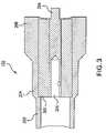
- FIG. 4is a cross-sectional, side view of second housing 104
- FIG. 5is a cross-sectional, perspective view of second housing 104 , both views according to one embodiment.
- housing 104may be generally cylindrical. Housing 104 may also have a first end section 402 (i.e., the section to the left of dotted line C), a second end section 406 (i.e., the section to the right of dotted line A), and an interim section 404 located between end sections 402 and 406 (i.e., the section between dotted lines B and C).
- Each section 402 , 404 and 406may have an outer-diameter and an inner-diameter and define a cavity.
- end section 402defines a cavity 401 and end section 406 defines cavity 411 .
- Transition section 403between end section 402 and interim section 404 .
- Transition section 403has a non-uniform outer-diameter. As shown in FIG. 4 , at its largest, the outer-diameter of section 403 is equal or about equal to the outer-diameter of section 404 , and, at its smallest, the outer-diameter of section 403 is equal or about equal to the outer-diameter of section 402 .
- interim section 404may include an inwardly projecting annular rib 422 . Additionally, a first recess 424 a and a second recess 424 b , both of which may be annular, may be formed in an inner surface 462 of interim section 404 . First recess 424 a may be located between rib 322 and interim section 403 . Second recess 424 b may be located between rib 322 and end section 406 .
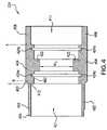
- FIGS. 6 and 7illustrate two conductive ground contacts 630 a and 630 b and a lock ring 642 housed in housing 104 .
- Ground contact 630is further illustrated in FIGS. 8 and 9 .
- FIG. 8is a side view of ground contact 630 and FIG. 9 is a perspective view of ground contact, both according to one embodiment.
- ground contactmay be generally ring shaped and have a body section 632 and a flange section 631 connected to body section 632 and projecting outwardly from an outer surface of body section 632 .
- body section 632is generally conical (e.g., the outer and inner diameter of body portion 632 gradually increases/decreases as one moves from one side of body section to the other side).
- Flange section 631may be disposed so that it projects outwardly from a portion of body section 632 where the outer-diameter is the greatest.
- FIG. 9illustrates that ground contact 630 may not form a complete ring. That is, ground contact has two ends 941 , 942 that generally face each other, but are separated by a small space or slit 933 . Thus, ground contact 630 may be referred to as a “split ring contact.”
- ground contact 630is received in recess 424 . More specifically, flange 631 a of ground contact 630 a is received in recess 424 a and flange 631 b of ground contact 630 b is received in recess 424 b .
- flange 631fits tightly in recess 424 so that when flange 631 is inserted into recess 424 the ground contact will be generally fixed in position.
- ground contacts 630 a,bare both positioned in housing 104 so that the wider side of the ground contact 630 is closer to end section 406 than the narrow side.
- lock ring 642may be disposed within the cavity 411 formed by end section 406 of housing 404 .
- lock ring 642is fastened to housing 404 so that it can not move relative to housing 104 in a direction parallel to the longitudinal axis of housing 104 unless a relatively large force is applied to the lock ring in that direction.
- an adhesive or other fastenermay be used to fasten lock ring 642 to housing 104 .
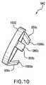
- lock ring 642includes a cylindrical or conical ring with one or more elastic locking arms 656 projecting from a side of the ring.
- the arms 656arranged at regular angular intervals around the rings circumference.
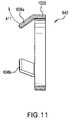
- FIGS. 10 and 11illustrate an embodiment of lock ring 642 in which lock ring 642 has three arms 656 (a.k.a., prongs 656 ) projecting from a ring 1002 .
- FIG. 10is a perspective view of lock ring 642
- FIG. 11is a cross-sectional, side view of lock ring 642 .
- the prongs 656project outwardly from generally one side of ring 1002 and are angled inwardly towards the center of the ring.
- lock ring 642functions to “lock” plug 160 in place when plug 160 is inserted into socket 158 .
- FIG. 12is a cross-sectional, side view of shroud 106 and FIG. 13 is a cross-sectional, perspective view of shroud 106 , both views according to one embodiment.
- shroud 106may have an outer wall 1202 , an inner wall 1204 , and a connecting wall 1206 connecting the inner wall 1204 to the outer wall 1202 .
- walls 1202 , 1204 and 1206are each in the form of a ring.
- outer ring wall 1202encloses a space 1201 and inner ring wall 1204 is disposed in space 1201 and is coaxial with outer ring wall 1202 .
- connecting wall 1206is connected between an end 1221 of wall 1202 and an end 1222 of wall 1204 .
- Walls 1202 , 1204 , and 1206define a space 1230 .
- the length ( 11 ) of inner wall 1204is significantly less than the length ( 12 ) of outer wall 1204 .
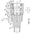
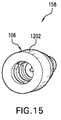
- FIG. 14is a cross-sectional, side view of socket 158 and FIG. 15 is a perspective view of socket 158 , both views according to one embodiment.
- end section 206 of first housing 102is disposed within cavity 401 such that end section 206 abuts wall 412 . Accordingly, at least a portion of first housing 102 is housed within second housing 104 .
- the distance from wall 412 to end 464 of section 402 of housing 104is greater than the length of end section 206 of housing 102 such that end 464 overhangs at least a portion of transition section 203 of housing 102 .
- end 464 ofmay be bent downwardly towards housing 102 .
- second housing 104is disposed within cavity 1201 formed by wall 1202 .
- end section 406 and interim section 404 of second housingare disposed in cavity 1201 .
- at least a portion of end section 406 and lock ring 642are disposed in the space 1230 formed by walls 1202 , 1204 and 1206 of shroud 106 .
- the projecting arms 656are not disposed in space 1230 .
- shroud 106be fixed to housing 104 .
- Shroud 106may be fixed to housing 104 by inserting end section 406 and interim section 404 of second housing into cavity 1201 as shown in FIG. 14 , and then folding down end portion 1250 of wall 1202 so that when shroud 106 is moved relative to housing 104 in the direction of arrow A, folded over end portion 1250 eventually contacts a surface of interim section 403 , thereby preventing further movement of shroud 106 relative to housing 104 .
- shroud 106is fixed to housing 104 in such a way that shroud 106 can move in a direction parallel to the longitudinal axis A of socket 158 between an “unlocked” and a “locked” position.
- the locked positionthere is a gap 1430 between wall 1206 and the end 1420 of end section 406 of housing 104 , and in the unlocked position the gap 1430 is either reduced or removed completely so that end 1420 abuts wall 1206 .
- wall 1204contacts arm 656 and exerts a force on arm 656 that causes arm 656 to flex outwardly.
- wall 1204contacts arm 656 a and exerts a force thereon that causes arm 656 a to flex outwardly in the direction of arrow A 11 (see FIGS. 11 and 14 ).
- shroud 106will automatically return to the locked position because, due to the elasticity of arm 656 , arm 656 exerts a force on wall 1204 in the direction of arrow A (see FIG. 14 ), which force will cause the entire shroud 106 to move in the direction of arrow A and into the locked position.
- FIG. 16is a side view of plug 160
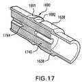
- FIG. 17is a cross-sectional, perspective view of plug 160
- FIG. 10is a cross-sectional, side view of plug 160 , all according to one embodiment.
- plug 160includes a generally cylindrical, conductive plug housing 1638 .
- plug housing 1638houses an insulator 1740 , and a contact 1744 , which may be male and/or female, is disposed fixedly within insulator 1740 .
- housing 1638On its outer wall, housing 1638 preferably has a protuberance 1690 having a first sloping surface 1691 on one side thereof and a second sloping surface 1692 on an opposite side thereof. Protuberance 1690 may be disposed axially about housing 1638 . As further described below, protuberance 1690 functions with lock ring 642 to retain plug 160 in socket 158 after plug 160 has been fully inserted into socket 158 .
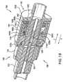
- FIGS. 19 and 20show plug 160 fully inserted into socket 158 , according to an embodiment.
- plug contact 1744conductively mates with socket contact 304 .
- plug contact 1744is a female contact while socket contact 304 is a male contact.
- plug contact 1644is a female connector while socket contact 310 is a male connector.
- protuberance 1690 and lock ring 642cooperate to “lock” plug 160 inside of socket 158 . That is, protuberance 1690 and lock ring 642 prevent contacts 304 and 1744 from becoming unmated because protuberance 1690 and lock ring 642 limit plug 160 's movement in the direction of arrow Z (see FIG. 20 ).
- the sloping surface 1691 of protuberance 1690is the first portion of protuberance 1690 to contact projecting arm 656 of lock ring 642 . Because arm 656 is somewhat elastic, when plug 160 is pushed into socket 158 , sloping surface 1691 urges arm 656 to move outwardly allowing protuberance 1690 to pass under arm 656 . Once protuberance 1690 has passed under arm 656 , the arm 656 automatically moves back to its original position, as shown in FIGS. 19 and 20 .
- an end 1090 of arm 656is positioned opposite of surface 1692 of protuberance 1690 .
- surface 1692will contact end 1090 of arm 656 and exert a force on arm 656 in the direction of arrow Z.
- Arm 656is connected to band 1002 and band 1002 is fixed to housing 104 , which is fixed to housing 102 .
- arm 656is not free to move in the direction of arrow Z relative to housing 104 .
- arm 656will exert an equal and opposite force on surface 1692 , thereby preventing plug 160 from moving relative to socket 150 in the direction of arrow Z.
- surface 1692is angled with respect to outer surface of housing 1638 such that, when surface 1692 exerts forces on arm 656 , arm 656 is not urged outwardly.
- shroud 106To remove plug 160 from socket 158 , one moves shroud 106 from its steady state “locking” position to an “unlocked” position. To move shroud to the unlocked position, shroud 106 is moved relative to housing 104 a distance in the direction of arrow X (see FIGS. 19 and 20 ). The distance needs to be great enough so that wall 1202 contacts arm 656 (e.g., arm 656 a ) and urges arm 656 upwardly to an extent that protuberance 1690 can pass under arm 656 . When shroud 106 is in its unlocked position, one can remove plug 160 from socket 150 by pulling on plug 160 in the Z direction.
- arm 656e.g., arm 656 a
- ground contacts 630preferably are split ring ground contacts (see FIG. 9 ) and have an inner diameter that is smaller than an outer diameter of a front portion 1601 of plug housing 1638 . Accordingly, in this embodiment, when plug 160 is inserted into socket 158 , front portion 1601 contacts an inner surface 601 of the body portion 632 and exerts a radial force on body portion 632 that causes contact 630 to open (i.e., causes gap 933 to grow wider). Body portion 632 responds to this force by exerting a radial force on housing 1638 . These forces between ground contacts 630 and conductive housing 1638 create a good electrical connection between contacts 630 and housing 1638 .
- socket 158 and plug 160are configured so that when plug 160 is fully inserted into socket 158 surface 1691 of housing 1638 is in contact with and exerts a radial and axial force on inner surface 601 of ground contact 630 b , causing gap 933 to expand and causing contact 630 b to exert a radial and axial force on housing 1638 .
- the axial force exerted on housing 1638 by contact 630 bis exerted in the direction of arrow Z.
- plug housing 1638may be disposed conductively within annular rib 422 .
- an inner diameter (id 5 ) (see FIG. 4 ) of annular rib 422may guide cylindrical plug housing 1638 during insertion into socket 158 .
- housing 1638may be press fit inside annular rib 422 .
- housing 1638may be slip fit inside rib 422 .
- FIG. 21is a side view of a snap lock connector apparatus 2100 according to another embodiment of the present invention.
- Connector apparatus 2100includes a first connector component 2158 (a.k.a., “socket 2158 ”) and second connector component 160 (a.k.a., “plug 160 ”).
- socket 2158is designed to receive plug 160 , as shown in FIG. 21 .
- socket 2158may include a housing 2102 (a.k.a., “socket body 2102 ” or “body 2102 ”) and a shroud 2106 .
- FIG. 22is an exploded view of socket 2158 according to some embodiments. Accordingly, FIG. 22 illustrates the components of socket 2158 according to some embodiments.
- socket 2158includes housing 2102 , an inner contact 2204 , a dielectric body 2204 (a.k.a., “insulator 2204 ”), an outer contact 2206 or (a.k.a., ground contact 2206 ), a lock ring 2208 , and shroud 2106 .
- FIG. 22shows inner contact 2204 being a male contact, but, in other embodiments, inner contact 2204 may be a female contact or other contact.
- housing 2102houses insulator 2204 , inner contact 2202 and outer contact 2206 , a front portion of housing 2202 is inserted into a rear opening defined by lock ring 2208 , and lock rings 2208 fits within shroud 2106 .
- outer contact 2206 and/or other components of the socketmay be not utilized.
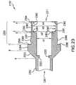
- FIG. 23is a cross-sectional, side view of housing 2102 and FIG. 24 is a perspective view of housing 2102 , both views according to one embodiment.
- housing 2102may be generally cylindrical. Housing 2102 may also have a first end section 2302 (i.e., the section to the left of dotted line A), a second end section 2306 (i.e., the section to the right of dotted line C), and an interim section 2304 located between end sections 2302 and 2306 (i.e., the section between dotted lines B and C).
- Each section 2302 , 2304 and 2306may have an outer-diameter and an inner-diameter and define a cavity.
- end section 2302defines a cavity 2301 and end section 2306 defines cavity 2311 .
- an annular rib 2399 that extends outwardlyis disposed on end section 2306 .
- rib 2399is disposed adjacent to but slightly spaced from a wall 2398 formed at the junction of sections 2304 and 2306 .
- Transition section 2303between end section 2302 and interim section 2304 .
- Transition section 2303has a non-uniform outer-diameter. As shown in FIG. 23 , at its largest, the outer-diameter of section 2303 is equal or about equal to the outer-diameter of section 2304 , and, at its smallest, the outer-diameter of section 2303 is equal or about equal to the outer-diameter of section 2302 . As shown in FIG. 23 , transition section 2303 may include an inwardly projecting annular rib 2322 .
- end section 2306may consist of end portions 2391 and 2394 and interim portions 2392 and 2393 . As shown, end portion 2391 is directly between interim portion 2391 and interim section 2304 , interim portion 2392 is directly between end portion 2391 and interim portion 2393 , and interim portion 2393 is directly between interim portion 2392 and end portion 2394 .
- portions 2391 - 2394may be have substantially the same outer diameter but different inner diameters.
- the inner diameter of portion 2391i.e., “id 1 ”
- the inner diameter of portion 2392i.e., “id 2 ”
- id 2is less than id 3 (i.e., the inner diameter of portion 2393 ).
- id 2may equal id 4 , which is the inner diameter of end portion 2394 .
- a wall 2383is formed by portions 2391 and 2392 .
- walls 2381 and 2382are formed by portions 2392 and 2393 and 2394 and 2393 , respectively.
- wall 2383may function as a stopper that stops movement of plug 160 when plug 160 is inserted in to socket 2158 . That is, in some embodiments id 1 is less than the outer diameter of plug 160 while id 2 is greater than the outer diameter of plug 160 so that when plug 160 is inserted in to socket 2158 the tip of plug 160 may contact wall 2383 (e.g., see FIG. 34 ), which stops the forward movement of plug 160 .
- FIG. 25illustrates insulator 2204 and contact 2202 housed in housing 2102 .
- contact 2202is elongate and has a longitudinal axis that is aligned with the longitudinal axis of insulator 2204 and the longitudinal axis of housing 2102 .
- Insulator 2204surrounds at least a portion of contact 2202 and functions to electrically insulate contact from housing 2102 , which is electrically conductive.
- Insulator 2204is positioned within housings 2102 such that a end 2501 of insulator 2204 abuts or is adjacent to annular rib 2232 and an opposite end 2502 is substantially flush with wall 2383 .
- FIG. 25also illustrates outer contact 2206 being housed in housing 2102 . More specifically, in the embodiment shown, outer contact 2206 is disposed and retained between annular walls 2381 and 2382 that bound and define interim portion 2393 . Outer contact 2206 , according to one embodiment, is further illustrated in FIG. 26 .
- FIG. 26is a perspective view of contact 2206 according to one embodiment.
- contact 2206may be annular (e.g., shaped like a ring).
- contact 2206is a split ring (i.e., contact 2206 is generally ring shaped and has a gap 2699 between the ends of contact 2206 ).
- contact 2206includes a first split ring 2601 , a second split ring 2602 and one or more generally U shaped contacts 2604 connecting the first ring 2601 with the second ring 2602 .
- rings 2601 and 2602have substantially the same inner and outer diameters, but the width of ring 2601 is substantially greater then the width of ring 2602 .
- rings 2601 and 2602are preferably arranged so that they are coaxial (e.g., they share a common central axis A), and generally U shaped contact(s) 2604 curve inwardly towards the central axis A.
- contact 2206is held tightly within an annular groove 2387 defined by walls 2381 and 2382 and the inner wall of portion 2393 . Further, contact 2206 is arranged so that it is coaxial with housing 2102 . That is, contact and housing have a common central axis.
- FIG. 27is a cross-sectional side view of partially assembled socket 2158 .
- FIG. 27shows end section 2306 of housing 2102 inserted into proximal end of lock ring 2208 .
- the length of section 2306is less than the length of lock ring 2208 so that when end section is fully inserted into lock ring 2208 , a front portion 2702 of lock ring 2208 extends beyond the end 2704 of end section 2306 .
- the inner-diameter of the proximal end of lock ring 2208is only slightly larger than the outer-diameter of section 2306 , thereby creating a snug fit between the components when they are mated.
- lock ring 2208is fixed to housing 2102 so that lock ring 2208 can not move in the direction of arrow A even when a significant force is exerted on lock ring 2208 in the direction of arrow A.
- annular rib 2399may be provided. That is, annular rib 2399 may be employed to prevent or assist in preventing lock ring 2208 from being able to move in the direction of arrow A after housing 2102 and lock ring 2208 are fully mated.
- lock ring 2208may have a tab 2799 projecting from an inner surface of a base ring 2798 portion of lock ring 2208 , which tab cooperates with annular rib 2399 to fix lock ring 2208 to housing 2102 .
- FIG. 28further illustrates lock ring 2208 according to one embodiment.
- lock ring 2208includes base ring 2798 and one or more fingers 2804 attached to base ring 2798 .
- Finger(s) 2804may be integrally attached to base ring 2798 so that base ring 2798 and finger(s) 2804 form a single unit.
- fingers 2804extend in the same general direction as the central axis 2890 of base ring 2798 . That is, in some embodiments, the longitudinal axis of each finger 2804 is generally parallel (but not precisely parallel) with the central axis 2890 of base ring 2798 .
- each finger 2804there is about a 2 degree angle between the longitudinal axis of each finger 2804 and the central axis 2890 of lock ring 2208 .
- the fingers 2804are arranged at regular angular intervals around base ring 2798 .
- FIG. 29is a cross-sectional view of lock ring 2208 and FIG. 30 is a cross-sectional view of one of the fingers 2804 of lock ring 2208 .
- fingers 2804are arranged at regular angular intervals around base ring 2798 and each finger has a proximal end 2902 connected to base ring 2798 and an opposite distal end or “tip” 2904 .
- tipdistal end
- FIG. 30spaced inwardly from distal end 2904 is a lock tab 3002 that projects from the inner surface 3001 of finger 2804 towards the central axis of lock ring 2208 .
- lock tab 3002has a planar back wall 3010 generally facing proximal end 2902 and a planar front wall generally facing distal end 2904 .
- Back wall 3010lies on a plane that forms an angle Y with the central axis 2890 of lock ring 2208 .
- angle Yis 90 degrees or thereabout.
- Front wall 3011is angled towards back wall 3010 and lies on a plane that forms an angle X with the central axis 2890 of lock ring 2208 .
- angle Xis between 20 and 60 degrees or thereabout. In one particular embodiment, angle X is about 36 degrees.
- a rounded bottom wall 3012connects front wall 3011 with back wall 3010 .
- FIG. 31is a cross-sectional, side view of shroud 2106 and FIG. 32 is a cross-sectional, perspective view of shroud 2106 , both views according to one embodiment.
- shroud 2106may have an outer wall or “outer sleeve” 3102 , an inner wall or “inner sleeve” 3104 , and a connecting member 3106 connecting the inner wall 3104 to the outer wall 3102 .
- walls 3102 and 3104are each in the form of a ring.
- outer ring wall 3102encloses a space 3190 and inner ring wall 3104 is disposed in space 3190 and is coaxial with outer ring wall 3102 .
- connecting member 3106is connected between an end of wall 3102 and an end wall 3104 .
- Walls 3102 and 3104 and member 3106define a space 3130 .
- the length (L 1 ) of inner wall 3104is significantly less than the length (L 2 ) of outer wall 3102 .
- Inner wall 3104has two major sides, an inner side 3170 and an outer side 3171 .
- Inner side 3170 of wall 3104defines an opening 3199 .
- outer side 3171is not parallel with respect to inner side 3170 so that in some embodiments the two sides converge to form an annular ridge 3175 .
- FIG. 33is a cross-sectional, side view of socket 2158 , according to one embodiment, after it is fully assembled. As shown, in FIG. 33 , when socket 2158 is fully assembled, end portion 2306 of housing 2102 is inserted into lock ring 2208 and then that assembly of components is inserted into shroud 2106 such that shroud surrounds end portion 2306 and lock ring 2208 .
- shroud 2106be fixed to housing 2102 .
- Shroud 2106may be fixed to housing 2102 by inserting end section 2306 into shroud 2106 as shown in FIG. 33 , and then folding down end portion 3390 of wall 3102 so that when shroud 2106 is moved relative to housing 2102 in the direction of arrow A in FIG. 33 , folded over end portion 3390 eventually contacts a surface of transition section 2303 of housing 2102 , thereby preventing further movement of shroud 2106 relative to housing 2102 in the direction of arrow A.
- shroud 2106is fixed to housing 2102 in such a way that shroud 2106 can move in a direction parallel to the longitudinal axis of socket 2158 between an “unlocked” and a “locked” position.
- shroud 2106is moved in the direction of arrow B so that ridge 3175 contacts and presses against the surface 3011 of lock tabs 3002 of fingers 2804 , thereby exerting a force on the fingers 2804 , which force causes the fingers 2804 to flex outwardly.
- FIG. 33shows shroud 2106 positioned in the locked position. As shown in FIG. 33 , in this embodiment, ridge 3175 does not press against the surface 3011 of lock tabs 3002 , but rather contacts or is adjacent to the tips 2904 of fingers 2804 . It should be noted that space 3130 is configured to receive tips 2904 when shroud 2106 is moved into the unlocked position.
- shroud 2106will automatically return to the locked position because, due to the elasticity of fingers 2804 , fingers 2804 will exert a force on shroud 2106 in the direction of arrow A, which force will cause the shroud 2106 to move in the direction of arrow A and into the locked position.
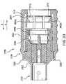
- FIG. 34shows plug 160 fully inserted into socket 2158 , according to an embodiment.
- plug contact 1744conductively mates with socket contact 2202 .
- plug contact 1744is a female contact while socket contact 2202 is a male contact.
- plug contact 1644is a female contact while socket contact 310 is a male contact.
- protuberance 1690 and the fingers 2804 of lock ring 2208cooperate to “lock” plug 160 inside of socket 2158 . That is, protuberance 1690 and lock ring 2208 prevent contacts 2202 and 1744 from becoming unmated because protuberance 1690 and lock ring 2208 limit plug 160 's movement in the direction of arrow Z.
- the sloping surface 1691 of protuberance 1690is the first portion of protuberance 1690 to contact the lock tab 3002 of fingers 2804 .
- fingers 2804are somewhat springy, when plug 160 is pushed into socket 2158 , sloping surface 1691 presses against surface 3011 of fingers 2804 , thereby causing fingers 2804 to move outwardly allowing protuberance 1690 to pass under the lock tabs 3002 (lock tabs 3002 a and 3002 b are shown in FIG. 34 ).
- the fingers 2804automatically return to their original position, as shown in FIG. 34 .
- each finger 2804When fingers 2804 return to their original position, the back wall 3010 of each finger 2804 is positioned opposite and facing surface 1692 of protuberance 1690 . Thus, if one attempts to move plug 160 relative to socket 2158 in the direction of arrow Z, surface 1692 will contact back wall 3010 of each finger 2804 and exert a force thereon in the direction of arrow Z. In a preferred embodiment, wall 3010 exerts a substantially equal and opposite force on surface 1692 because, as discussed above, lock ring 2208 is preferably fixed to housing 2102 . Accordingly, unless shroud 2106 is in the unlocked position, pushing or pulling on plug 160 in the direction of arrow Z will not (in most cases) remove plug 160 from socket 2158 . That is, when shroud 2106 is in the locked position, only a large pulling/pushing force on plug 160 will disengage plug 160 from socket 2158 .
- shroud 2106to remove plug 160 from socket 2158 , one moves shroud 2106 from its steady state locked position to the unlocked position. As discussed above, to move shroud to the unlocked position, shroud 2106 is moved relative to housing 2102 a distance in the direction of arrow X (see FIG. 34 ). The distance needs to be great enough so that inner sleeve 3104 contacts and presses against the lock tables 3002 of fingers 2804 , thereby urging fingers 2804 upwardly to an extent that protuberance 1690 can pass under the lock tabs 3002 . When shroud 2106 is in its unlocked position, one can remove plug 160 from socket 150 by pulling on plug 160 in the Z direction with a minimal amount of force.
- contact 2206preferably is a split ring (see FIG. 26 ).
- plug 160When plug 160 is inserted into socket 158 , at least a part of front portion 1601 contacts an inner surface of contact 2206 and exerts a radial force on contact 2206 that causes contact 2206 to open (i.e., causes gap 2699 to grow wider).
- Contact 2206responds to this force by exerting a radial force on housing 1638 .
- This force between ground contact 2206 and conductive housing 1638creates a good electrical connection between contact 2206 and housing 1638 .
- at least a part of front portion 1601contacts the inner surface of U shaped contacts 2604 but does not contact either split ring 2601 or 2602 .
- the distance (d 1 —see FIG. 27 ) from wall 2383 to back wall 3010 of lock tab 3002is equal or about equal to the distance (d 2 —see FIG. 18 ) from the front end of plug 160 to a point at the bottom of surface 1692 of protuberance 1690 .
- wall 2383functions as a stopper that limits how far plug can be inserted into socket 2158 .
- FIG. 35is a cross-sectional, side view of a snap lock connector apparatus 3500 according to another embodiment.
- Connector apparatusis similar to connector apparatus 2100 .
- the main difference between connector apparatus 3500 and apparatus 2100is that when plug 160 is inserted into the distal end of socket 2158 and locked within socket 2158 by lock ring 2208 , the tip 3533 of front portion 1601 of plug housing 1638 does not contact wall 2383 of housing 2102 . That is, in the alternative embodiment, when plug 160 is fully inserted and locked within socket 2158 , there exists a gap between tip 3533 and wall 2383 . In some embodiments, the gap is at least about 0.005 inches wide.
- the fingers 2804may exert an axial force on plug 160 by pressing against protuberance 1690 , but the axial force does not causes the front surface 3533 of plug 160 to press against wall 2383 .
Landscapes
- Details Of Connecting Devices For Male And Female Coupling (AREA)
- Coupling Device And Connection With Printed Circuit (AREA)
Abstract
Description
Claims (48)
Priority Applications (1)
| Application Number | Priority Date | Filing Date | Title |
|---|---|---|---|
| US11/710,416US7329139B2 (en) | 2005-02-11 | 2007-02-26 | Snap lock connector |
Applications Claiming Priority (4)
| Application Number | Priority Date | Filing Date | Title |
|---|---|---|---|
| US65163705P | 2005-02-11 | 2005-02-11 | |
| US70030905P | 2005-07-19 | 2005-07-19 | |
| US11/296,336US7189097B2 (en) | 2005-02-11 | 2005-12-08 | Snap lock connector |
| US11/710,416US7329139B2 (en) | 2005-02-11 | 2007-02-26 | Snap lock connector |
Related Parent Applications (1)
| Application Number | Title | Priority Date | Filing Date |
|---|---|---|---|
| US11/296,336ContinuationUS7189097B2 (en) | 2005-02-11 | 2005-12-08 | Snap lock connector |
Publications (2)
| Publication Number | Publication Date |
|---|---|
| US20070173100A1 US20070173100A1 (en) | 2007-07-26 |
| US7329139B2true US7329139B2 (en) | 2008-02-12 |
Family
ID=36816237
Family Applications (2)
| Application Number | Title | Priority Date | Filing Date |
|---|---|---|---|
| US11/296,336ActiveUS7189097B2 (en) | 2005-02-11 | 2005-12-08 | Snap lock connector |
| US11/710,416ActiveUS7329139B2 (en) | 2005-02-11 | 2007-02-26 | Snap lock connector |
Family Applications Before (1)
| Application Number | Title | Priority Date | Filing Date |
|---|---|---|---|
| US11/296,336ActiveUS7189097B2 (en) | 2005-02-11 | 2005-12-08 | Snap lock connector |
Country Status (8)
| Country | Link |
|---|---|
| US (2) | US7189097B2 (en) |
| EP (1) | EP1846988A4 (en) |
| JP (1) | JP2008530754A (en) |
| KR (1) | KR101160322B1 (en) |
| CN (1) | CN101116228B (en) |
| AU (1) | AU2006214647C1 (en) |
| CA (1) | CA2597664C (en) |
| WO (1) | WO2006088639A1 (en) |
Cited By (52)
| Publication number | Priority date | Publication date | Assignee | Title |
|---|---|---|---|---|
| US20080045082A1 (en)* | 2006-08-15 | 2008-02-21 | Hon Hai Precision Ind. Co., Ltd. | Electrical connector |
| US20080224944A1 (en)* | 2007-03-15 | 2008-09-18 | Chung-Chuan Huang | Combination of antenna terminal and reception member |
| US20090305560A1 (en)* | 2008-06-04 | 2009-12-10 | Hon Hai Precision Industry Co., Ltd. | Coxial connector having risilient ring and sealing ring |
| US20100029118A1 (en)* | 2008-07-30 | 2010-02-04 | Aliner Industries Inc. | Quick release connector device |
| US20100111477A1 (en)* | 2007-04-20 | 2010-05-06 | Huber + Suhner Ag | Optical connector |
| US7758370B1 (en)* | 2009-06-26 | 2010-07-20 | Corning Gilbert Inc. | Quick release electrical connector |
| US20100304598A1 (en)* | 2009-06-01 | 2010-12-02 | Thomas Kari | Coaxial connector with coupling spring |
| US20110092833A1 (en)* | 2009-10-21 | 2011-04-21 | Tyco Healthcare Group Lp | ECG Lead System |
| US7938680B1 (en)* | 2010-04-13 | 2011-05-10 | Ezconn Corporation | Grounding electrical connector |
| US20130084741A1 (en)* | 2010-04-09 | 2013-04-04 | Fci Automotive Holding | Electromagnetic Shielding Device |
| US20130122735A1 (en)* | 2010-10-12 | 2013-05-16 | Wolfgang Pfeiffer | Electrical plug-in connector comprising a raised release element, and method for reversibly connecting and disconnecting plug parts of a plug-in connector |
| US8568160B2 (en) | 2010-07-29 | 2013-10-29 | Covidien Lp | ECG adapter system and method |
| US8634901B2 (en) | 2011-09-30 | 2014-01-21 | Covidien Lp | ECG leadwire system with noise suppression and related methods |
| US8668651B2 (en) | 2006-12-05 | 2014-03-11 | Covidien Lp | ECG lead set and ECG adapter system |
| US8690611B2 (en) | 2007-12-11 | 2014-04-08 | Covidien Lp | ECG electrode connector |
| US8821405B2 (en) | 2006-09-28 | 2014-09-02 | Covidien Lp | Cable monitoring apparatus |
| US8888526B2 (en) | 2010-08-10 | 2014-11-18 | Corning Gilbert, Inc. | Coaxial cable connector with radio frequency interference and grounding shield |
| US9048599B2 (en) | 2013-10-28 | 2015-06-02 | Corning Gilbert Inc. | Coaxial cable connector having a gripping member with a notch and disposed inside a shell |
| US9071019B2 (en) | 2010-10-27 | 2015-06-30 | Corning Gilbert, Inc. | Push-on cable connector with a coupler and retention and release mechanism |
| USD737979S1 (en) | 2008-12-09 | 2015-09-01 | Covidien Lp | ECG electrode connector |
| US9136654B2 (en) | 2012-01-05 | 2015-09-15 | Corning Gilbert, Inc. | Quick mount connector for a coaxial cable |
| US9147963B2 (en) | 2012-11-29 | 2015-09-29 | Corning Gilbert Inc. | Hardline coaxial connector with a locking ferrule |
| US9153911B2 (en) | 2013-02-19 | 2015-10-06 | Corning Gilbert Inc. | Coaxial cable continuity connector |
| US9166348B2 (en) | 2010-04-13 | 2015-10-20 | Corning Gilbert Inc. | Coaxial connector with inhibited ingress and improved grounding |
| US9172154B2 (en) | 2013-03-15 | 2015-10-27 | Corning Gilbert Inc. | Coaxial cable connector with integral RFI protection |
| US9190744B2 (en) | 2011-09-14 | 2015-11-17 | Corning Optical Communications Rf Llc | Coaxial cable connector with radio frequency interference and grounding shield |
| US9287659B2 (en) | 2012-10-16 | 2016-03-15 | Corning Optical Communications Rf Llc | Coaxial cable connector with integral RFI protection |
| US9407016B2 (en) | 2012-02-22 | 2016-08-02 | Corning Optical Communications Rf Llc | Coaxial cable connector with integral continuity contacting portion |
| US9408546B2 (en) | 2013-03-15 | 2016-08-09 | Covidien Lp | Radiolucent ECG electrode system |
| US9408547B2 (en) | 2011-07-22 | 2016-08-09 | Covidien Lp | ECG electrode connector |
| USD771818S1 (en) | 2013-03-15 | 2016-11-15 | Covidien Lp | ECG electrode connector |
| US9525220B1 (en) | 2015-11-25 | 2016-12-20 | Corning Optical Communications LLC | Coaxial cable connector |
| US9548557B2 (en) | 2013-06-26 | 2017-01-17 | Corning Optical Communications LLC | Connector assemblies and methods of manufacture |
| US9548572B2 (en) | 2014-11-03 | 2017-01-17 | Corning Optical Communications LLC | Coaxial cable connector having a coupler and a post with a contacting portion and a shoulder |
| US9590287B2 (en) | 2015-02-20 | 2017-03-07 | Corning Optical Communications Rf Llc | Surge protected coaxial termination |
| US9693701B2 (en) | 2013-03-15 | 2017-07-04 | Covidien Lp | Electrode connector design to aid in correct placement |
| US9762008B2 (en) | 2013-05-20 | 2017-09-12 | Corning Optical Communications Rf Llc | Coaxial cable connector with integral RFI protection |
| US9859631B2 (en) | 2011-09-15 | 2018-01-02 | Corning Optical Communications Rf Llc | Coaxial cable connector with integral radio frequency interference and grounding shield |
| US10033122B2 (en) | 2015-02-20 | 2018-07-24 | Corning Optical Communications Rf Llc | Cable or conduit connector with jacket retention feature |
| US10211547B2 (en) | 2015-09-03 | 2019-02-19 | Corning Optical Communications Rf Llc | Coaxial cable connector |
| US20190067881A1 (en)* | 2011-11-02 | 2019-02-28 | Ppc Broadband, Inc. | Continuity providing port |
| US10290958B2 (en) | 2013-04-29 | 2019-05-14 | Corning Optical Communications Rf Llc | Coaxial cable connector with integral RFI protection and biasing ring |
| US10587078B2 (en) | 2016-06-22 | 2020-03-10 | HARTING Electronics GmbH | Plug connector |
| US10630034B2 (en) | 2015-05-27 | 2020-04-21 | Amphenol Corporation | Integrated antenna unit with blind mate interconnect |
| US10756455B2 (en) | 2005-01-25 | 2020-08-25 | Corning Optical Communications Rf Llc | Electrical connector with grounding member |
| US11342718B2 (en) | 2015-03-27 | 2022-05-24 | CommScope Connectivity Spain, S.L. | Latch for telecommunications connector |
| US11356751B2 (en) | 2017-06-19 | 2022-06-07 | Commscope Technologies Llc | High density bezel for patch panel |
| US11356752B2 (en) | 2017-11-10 | 2022-06-07 | Commscope Technologies Llc | Telecommunications panel with grounding wire |
| US11367985B2 (en) | 2016-08-15 | 2022-06-21 | Commscope Technologies Llc | Connector assembly with grounding |
| US11509105B2 (en) | 2015-03-20 | 2022-11-22 | CommScope Connectivity Spain, S.L. | Connector with separable lacing fixture |
| US12034264B2 (en) | 2021-03-31 | 2024-07-09 | Corning Optical Communications Rf Llc | Coaxial cable connector assemblies with outer conductor engagement features and methods for using the same |
| US12206205B2 (en) | 2015-03-27 | 2025-01-21 | CommScope Connectivity Spain, S.L. | Cover assembly for a telecommunications connector |
Families Citing this family (32)
| Publication number | Priority date | Publication date | Assignee | Title |
|---|---|---|---|---|
| US7090516B2 (en)* | 2004-02-09 | 2006-08-15 | Adc Telecommunications, Inc. | Protective boot and universal cap |
| JP2009536426A (en)* | 2006-05-08 | 2009-10-08 | マルチ−ホールディング アクチェンゲゼルシャフト | Plug connector |
| CN2896603Y (en)* | 2006-09-29 | 2007-05-02 | 瞿金良 | Fast-plugging self-locking type radio coaxial connector |
| US7727012B2 (en)* | 2006-10-26 | 2010-06-01 | John Mezzalingua Associates, Inc. | Radial and thrust snap bearing retainer |
| JP4767923B2 (en)* | 2007-07-27 | 2011-09-07 | タイコエレクトロニクスジャパン合同会社 | Electrical connector and connector assembly |
| RU2010129045A (en) | 2007-12-14 | 2012-01-20 | Бристоль-Мейерз Сквибб Компани (US) | BINDING MOLECULES TO HUMAN RECEPTOR OX40 |
| PL2133958T3 (en)* | 2008-06-09 | 2011-07-29 | Interlemo Holding Sa | Female plug for self-locking connector system |
| US8113875B2 (en) | 2008-09-30 | 2012-02-14 | Belden Inc. | Cable connector |
| US8215884B2 (en) | 2008-12-16 | 2012-07-10 | Lockheed Martin Corporation | Connector for use in high vibration environment |
| US8272886B2 (en)* | 2009-11-13 | 2012-09-25 | Join Co., Ltd. | Connector |
| WO2011083391A2 (en) | 2010-01-05 | 2011-07-14 | Pfizer Inc. | Biomarkers for anti-igf-ir cancer therapy |
| CN101872927B (en)* | 2010-06-22 | 2013-06-19 | 中航光电科技股份有限公司 | Direct-breakoff type electric connector and plug thereof |
| CN101950897B (en)* | 2010-07-19 | 2013-03-27 | 中航光电科技股份有限公司 | Direct breakoff electric connector assembly and plug thereof |
| CH703474A2 (en)* | 2010-07-30 | 2012-01-31 | Huber+Suhner Ag | Coaxial connector. |
| PE20131465A1 (en) | 2010-09-09 | 2014-01-04 | Pfizer | UNION MOLECULES A 4-1 BB |
| GB2483498A (en)* | 2010-09-10 | 2012-03-14 | Miniflex Ltd | A water-resistant optical fibre connector with an elastomer sleeve providing both a water seal and a coupling force |
| US8157588B1 (en) | 2011-02-08 | 2012-04-17 | Belden Inc. | Cable connector with biasing element |
| KR101122551B1 (en)* | 2011-04-18 | 2012-03-20 | 남부대학교산학협력단 | Solar connector |
| GB201116092D0 (en) | 2011-09-16 | 2011-11-02 | Bioceros B V | Antibodies and uses thereof |
| US8915753B2 (en)* | 2011-12-12 | 2014-12-23 | Holland Electronics, Llc | Signal continuity connector |
| DE102011056466A1 (en)* | 2011-12-15 | 2013-06-20 | Telegärtner Karl Gärtner GmbH | Coaxial connector arrangement |
| DE102012100615B4 (en)* | 2012-01-25 | 2014-08-14 | HARTING Electronics GmbH | Connector system for connectors |
| SI2844282T1 (en) | 2012-05-04 | 2019-08-30 | Pfizer Inc. | Prostate-associated antigens and vaccine-based immunotherapy regimens |
| US8801453B1 (en) | 2013-02-21 | 2014-08-12 | Bourns, Inc. | Rotary connector having a housing and a locking ring |
| WO2014148895A1 (en) | 2013-03-18 | 2014-09-25 | Biocerox Products B.V. | Humanized anti-cd134 (ox40) antibodies and uses thereof |
| CN103401099B (en)* | 2013-08-06 | 2015-10-14 | 临沂市海纳电子有限公司 | A kind of connector with shielding contact spring |
| DE102015113086B4 (en)* | 2015-08-07 | 2020-04-09 | Norma Germany Gmbh | Connector device with cable connector and wind protection cover |
| CN108110514A (en)* | 2016-11-24 | 2018-06-01 | 周利明 | Socket, plug and electric connection structure |
| US10950994B2 (en)* | 2017-03-10 | 2021-03-16 | John Mezzalinguaassociates, Llc | Quick connect/disconnect coaxial cable connector |
| CN109638536B (en)* | 2018-11-30 | 2024-08-16 | 中航光电科技股份有限公司 | A connector assembly |
| CN110265819B (en)* | 2019-07-05 | 2025-03-18 | 上海航天科工电器研究院有限公司 | A radio frequency coaxial connector fixing device |
| CN113258368B (en)* | 2021-05-14 | 2025-05-06 | 湖南长高电气有限公司 | A branch busbar contact seat assembly structure |
Citations (49)
| Publication number | Priority date | Publication date | Assignee | Title |
|---|---|---|---|---|
| SU340537A1 (en) | К. Н. Логвинов, В. Н. Глущенко, В. Б. Борисенко, В. А. Алеко | DEVICE FOR FORMING CERAMIC PRODUCTS | ||
| US2711524A (en)* | 1952-10-08 | 1955-06-21 | American Phenolic Corp | Electrical contact |
| US2785384A (en) | 1955-02-23 | 1957-03-12 | Liquidometer Corp | Moisture proof means for connecting a coaxial cable to a fitting |
| US3161451A (en) | 1961-08-16 | 1964-12-15 | Multi Contact Neidecker & Co | Self-locking electric plug-and-jack connector |
| US3193309A (en) | 1961-02-13 | 1965-07-06 | Morris Arthur | Tubular connector having spring retaining means |
| FR2204331A5 (en) | 1972-10-24 | 1974-05-17 | Radiall Sa | |
| US3976352A (en) | 1974-05-02 | 1976-08-24 | Georg Spinner | Coaxial plug-type connection |
| US4012105A (en) | 1974-09-30 | 1977-03-15 | Bell Industries, Inc. | Coaxial electrical connector |
| US4017139A (en) | 1976-06-04 | 1977-04-12 | Sealectro Corporation | Positive locking electrical connector |
| US4106839A (en) | 1976-07-26 | 1978-08-15 | Automation Industries, Inc. | Electrical connector and frequency shielding means therefor and method of making same |
| US4165911A (en) | 1977-10-25 | 1979-08-28 | Amp Incorporated | Rotating collar lock connector for a coaxial cable |
| US4239318A (en)* | 1979-07-23 | 1980-12-16 | International Telephone And Telegraph Corporation | Electrical connector shield |
| US4326768A (en) | 1980-06-02 | 1982-04-27 | The Bendix Corporation | Electrical connector grounding strap connection |
| DE3117320A1 (en) | 1980-10-15 | 1982-04-29 | Siemens AG, 1000 Berlin und 8000 München | Coaxial angled element |
| US4426127A (en) | 1981-11-23 | 1984-01-17 | Omni Spectra, Inc. | Coaxial connector assembly |
| US4428639A (en)* | 1982-04-05 | 1984-01-31 | The Bendix Corporation | Electrical connector |
| US4666231A (en) | 1986-06-26 | 1987-05-19 | Amp Incorporated | Switching coaxial connector |
| US4674809A (en) | 1986-01-30 | 1987-06-23 | Amp Incorporated | Filtered triax connector |
| EP0299772A2 (en) | 1987-07-15 | 1989-01-18 | Amphenol Corporation | Data bus contact |
| US4834675A (en) | 1988-10-13 | 1989-05-30 | Lrc Electronics, Inc. | Snap-n-seal coaxial connector |
| EP0350835A2 (en) | 1988-07-12 | 1990-01-17 | W.L. Gore & Associates GmbH | Electrical connector |
| US4957456A (en) | 1989-09-29 | 1990-09-18 | Hughes Aircraft Company | Self-aligning RF push-on connector |
| US4963105A (en) | 1989-03-03 | 1990-10-16 | Dynawave Incorporated | Electrical connector assembly |
| US5074809A (en) | 1989-01-20 | 1991-12-24 | Alliance Technique Industrielle | Ultraminiature high-frequency connection interface |
| US5088937A (en) | 1991-04-19 | 1992-02-18 | Amp Incorporated | Right angle coaxial jack connector |
| US5176533A (en) | 1991-05-31 | 1993-01-05 | Daiichi Denshi Kogyo Kabushiki Kaisha | Electrical connector |
| US5195904A (en) | 1990-12-18 | 1993-03-23 | Radiall | Coaxial electrical connector |
| EP0867978A2 (en) | 1997-03-27 | 1998-09-30 | Siemens Aktiengesellschaft | Angled coaxial connector |
| US5938465A (en) | 1997-10-15 | 1999-08-17 | Palco Connector, Inc. | Machined dual spring ring connector for coaxial cable |
| DE19749130C1 (en) | 1997-11-06 | 1999-08-26 | Siemens Ag | Electrical connector with quick lock |
| WO2000005785A1 (en) | 1998-07-22 | 2000-02-03 | Tyco Electronics Logistics Ag | Electrical connector with quick connection and method for producing a connector |
| US6083030A (en) | 1998-09-23 | 2000-07-04 | Osram Sylvania Inc. | Connector latch |
| US6093043A (en) | 1997-04-01 | 2000-07-25 | Itt Manufacturing Enterprises, Inc. | Connector locking mechanism |
| US6126487A (en) | 1997-02-04 | 2000-10-03 | Rosenberger Hochfrequenztechnik Gmbh And Co. | Coaxial connector socket |
| US6132234A (en)* | 1995-11-20 | 2000-10-17 | Wilheilm Sihn, Jr., Kg | Coaxial plug connector for communications technology, in particular in motor vehicles |
| US6142812A (en) | 1998-06-02 | 2000-11-07 | Kmw Co., Ltd. | Connector |
| EP1069654A1 (en) | 1999-07-16 | 2001-01-17 | Framatome Connectors International | Triaxial contact and process for assembling said contact |
| EP1094565A1 (en) | 1999-10-22 | 2001-04-25 | Huber+Suhner Ag | Coaxial connector |
| US6250942B1 (en) | 1999-08-30 | 2001-06-26 | Berg Technology, Inc. | Electrical connector with combined shield and latch |
| EP1115179A2 (en) | 1999-12-08 | 2001-07-11 | Amphenol Corporation | Adaptive coupling mechanism |
| US6332815B1 (en) | 1999-12-10 | 2001-12-25 | Litton Systems, Inc. | Clip ring for an electrical connector |
| US6379183B1 (en)* | 2000-03-31 | 2002-04-30 | Tektronix, Inc. | Adapter usable with an electronic interconnect for high speed signal and data transmission |
| US6464527B2 (en) | 2000-03-28 | 2002-10-15 | Ez Form Cable Corporation | Quick connect coaxial cable connector |
| US6645011B2 (en)* | 2001-08-03 | 2003-11-11 | Radiall | Coaxial connection with locking by snap-fastening |
| US6709289B2 (en)* | 2002-02-14 | 2004-03-23 | Huber & Suhner Ag | Electrical plug connector |
| DE10346914A1 (en) | 2002-10-10 | 2004-05-27 | Sumitomo Wiring Systems, Ltd., Yokkaichi | Connector for air bag of motor vehicle, has lock arm which fits into lock unit to release press state of slider arm with press unit and move slider to attachment position, during normal fitting of connector |
| US6749454B2 (en) | 2001-11-09 | 2004-06-15 | Escha Bauelemente Gmbh | Connector with snap collar |
| US20040137778A1 (en) | 2002-10-22 | 2004-07-15 | Kristof Mattheeuws | Electrical connector with a locking ring, especially a coaxial plug |
| US20060099853A1 (en)* | 2004-11-05 | 2006-05-11 | Fred Sattele | Coaxial plug connector and mating connector |
Family Cites Families (6)
| Publication number | Priority date | Publication date | Assignee | Title |
|---|---|---|---|---|
| JPS5965489U (en)* | 1982-10-25 | 1984-05-01 | 富士通株式会社 | coaxial connector |
| US5147221A (en)* | 1989-08-13 | 1992-09-15 | The Starling Manufacturing Company | Combination socket and wingless cable-end radio pin connector |
| US5257833A (en)* | 1991-09-25 | 1993-11-02 | Bundy Corporation | Metal retainer for quick connect tubing connector |
| JPH08227755A (en)* | 1995-02-21 | 1996-09-03 | Sumitomo Wiring Syst Ltd | Connecting structure of connector |
| JP2001110522A (en)* | 1999-10-05 | 2001-04-20 | Ryosei Electro-Circuit Systems Ltd | Lock structure of connector |
| US6921279B2 (en)* | 2003-06-05 | 2005-07-26 | Fci Americas Technology, Inc. | Electrical connector with connector position assurance member |
- 2005
- 2005-12-08USUS11/296,336patent/US7189097B2/enactiveActive
- 2006
- 2006-02-01AUAU2006214647Apatent/AU2006214647C1/ennot_activeCeased
- 2006-02-01CNCN2006800043547Apatent/CN101116228B/ennot_activeExpired - Fee Related
- 2006-02-01EPEP06734112Apatent/EP1846988A4/ennot_activeWithdrawn
- 2006-02-01KRKR1020077020664Apatent/KR101160322B1/ennot_activeExpired - Fee Related
- 2006-02-01CACA2597664Apatent/CA2597664C/ennot_activeExpired - Fee Related
- 2006-02-01WOPCT/US2006/003380patent/WO2006088639A1/enactiveApplication Filing
- 2006-02-01JPJP2007555127Apatent/JP2008530754A/enactivePending
- 2007
- 2007-02-26USUS11/710,416patent/US7329139B2/enactiveActive
Patent Citations (51)
| Publication number | Priority date | Publication date | Assignee | Title |
|---|---|---|---|---|
| SU340537A1 (en) | К. Н. Логвинов, В. Н. Глущенко, В. Б. Борисенко, В. А. Алеко | DEVICE FOR FORMING CERAMIC PRODUCTS | ||
| US2711524A (en)* | 1952-10-08 | 1955-06-21 | American Phenolic Corp | Electrical contact |
| US2785384A (en) | 1955-02-23 | 1957-03-12 | Liquidometer Corp | Moisture proof means for connecting a coaxial cable to a fitting |
| US3193309A (en) | 1961-02-13 | 1965-07-06 | Morris Arthur | Tubular connector having spring retaining means |
| US3161451A (en) | 1961-08-16 | 1964-12-15 | Multi Contact Neidecker & Co | Self-locking electric plug-and-jack connector |
| FR2204331A5 (en) | 1972-10-24 | 1974-05-17 | Radiall Sa | |
| US3976352A (en) | 1974-05-02 | 1976-08-24 | Georg Spinner | Coaxial plug-type connection |
| US4012105A (en) | 1974-09-30 | 1977-03-15 | Bell Industries, Inc. | Coaxial electrical connector |
| US4017139A (en) | 1976-06-04 | 1977-04-12 | Sealectro Corporation | Positive locking electrical connector |
| US4106839A (en) | 1976-07-26 | 1978-08-15 | Automation Industries, Inc. | Electrical connector and frequency shielding means therefor and method of making same |
| US4165911A (en) | 1977-10-25 | 1979-08-28 | Amp Incorporated | Rotating collar lock connector for a coaxial cable |
| US4239318A (en)* | 1979-07-23 | 1980-12-16 | International Telephone And Telegraph Corporation | Electrical connector shield |
| US4326768A (en) | 1980-06-02 | 1982-04-27 | The Bendix Corporation | Electrical connector grounding strap connection |
| DE3117320A1 (en) | 1980-10-15 | 1982-04-29 | Siemens AG, 1000 Berlin und 8000 München | Coaxial angled element |
| US4426127A (en) | 1981-11-23 | 1984-01-17 | Omni Spectra, Inc. | Coaxial connector assembly |
| US4428639A (en)* | 1982-04-05 | 1984-01-31 | The Bendix Corporation | Electrical connector |
| US4674809A (en) | 1986-01-30 | 1987-06-23 | Amp Incorporated | Filtered triax connector |
| US4666231A (en) | 1986-06-26 | 1987-05-19 | Amp Incorporated | Switching coaxial connector |
| EP0299772A2 (en) | 1987-07-15 | 1989-01-18 | Amphenol Corporation | Data bus contact |
| EP0350835A2 (en) | 1988-07-12 | 1990-01-17 | W.L. Gore & Associates GmbH | Electrical connector |
| US4834675A (en) | 1988-10-13 | 1989-05-30 | Lrc Electronics, Inc. | Snap-n-seal coaxial connector |
| US5074809A (en) | 1989-01-20 | 1991-12-24 | Alliance Technique Industrielle | Ultraminiature high-frequency connection interface |
| US4963105A (en) | 1989-03-03 | 1990-10-16 | Dynawave Incorporated | Electrical connector assembly |
| US4957456A (en) | 1989-09-29 | 1990-09-18 | Hughes Aircraft Company | Self-aligning RF push-on connector |
| US5195904A (en) | 1990-12-18 | 1993-03-23 | Radiall | Coaxial electrical connector |
| US5088937A (en) | 1991-04-19 | 1992-02-18 | Amp Incorporated | Right angle coaxial jack connector |
| US5176533A (en) | 1991-05-31 | 1993-01-05 | Daiichi Denshi Kogyo Kabushiki Kaisha | Electrical connector |
| US6132234A (en)* | 1995-11-20 | 2000-10-17 | Wilheilm Sihn, Jr., Kg | Coaxial plug connector for communications technology, in particular in motor vehicles |
| US6126487A (en) | 1997-02-04 | 2000-10-03 | Rosenberger Hochfrequenztechnik Gmbh And Co. | Coaxial connector socket |
| EP0867978A2 (en) | 1997-03-27 | 1998-09-30 | Siemens Aktiengesellschaft | Angled coaxial connector |
| US6093043A (en) | 1997-04-01 | 2000-07-25 | Itt Manufacturing Enterprises, Inc. | Connector locking mechanism |
| US5938465A (en) | 1997-10-15 | 1999-08-17 | Palco Connector, Inc. | Machined dual spring ring connector for coaxial cable |
| DE19749130C1 (en) | 1997-11-06 | 1999-08-26 | Siemens Ag | Electrical connector with quick lock |
| US6142812A (en) | 1998-06-02 | 2000-11-07 | Kmw Co., Ltd. | Connector |
| WO2000005785A1 (en) | 1998-07-22 | 2000-02-03 | Tyco Electronics Logistics Ag | Electrical connector with quick connection and method for producing a connector |
| US6083030A (en) | 1998-09-23 | 2000-07-04 | Osram Sylvania Inc. | Connector latch |
| EP1069654A1 (en) | 1999-07-16 | 2001-01-17 | Framatome Connectors International | Triaxial contact and process for assembling said contact |
| US6250942B1 (en) | 1999-08-30 | 2001-06-26 | Berg Technology, Inc. | Electrical connector with combined shield and latch |
| US6692286B1 (en) | 1999-10-22 | 2004-02-17 | Huber + Suhner Ag | Coaxial plug connector |
| EP1094565A1 (en) | 1999-10-22 | 2001-04-25 | Huber+Suhner Ag | Coaxial connector |
| EP1115179A2 (en) | 1999-12-08 | 2001-07-11 | Amphenol Corporation | Adaptive coupling mechanism |
| US6332815B1 (en) | 1999-12-10 | 2001-12-25 | Litton Systems, Inc. | Clip ring for an electrical connector |
| US6464527B2 (en) | 2000-03-28 | 2002-10-15 | Ez Form Cable Corporation | Quick connect coaxial cable connector |
| US6379183B1 (en)* | 2000-03-31 | 2002-04-30 | Tektronix, Inc. | Adapter usable with an electronic interconnect for high speed signal and data transmission |
| US6645011B2 (en)* | 2001-08-03 | 2003-11-11 | Radiall | Coaxial connection with locking by snap-fastening |
| US6749454B2 (en) | 2001-11-09 | 2004-06-15 | Escha Bauelemente Gmbh | Connector with snap collar |
| US6709289B2 (en)* | 2002-02-14 | 2004-03-23 | Huber & Suhner Ag | Electrical plug connector |
| DE10346914A1 (en) | 2002-10-10 | 2004-05-27 | Sumitomo Wiring Systems, Ltd., Yokkaichi | Connector for air bag of motor vehicle, has lock arm which fits into lock unit to release press state of slider arm with press unit and move slider to attachment position, during normal fitting of connector |
| US20040137778A1 (en) | 2002-10-22 | 2004-07-15 | Kristof Mattheeuws | Electrical connector with a locking ring, especially a coaxial plug |
| EP1455420A1 (en) | 2002-10-22 | 2004-09-08 | Tyco Electronics Belgium EC N.V. | Electrical connector with a locking ring, especially a coaxial plug |
| US20060099853A1 (en)* | 2004-11-05 | 2006-05-11 | Fred Sattele | Coaxial plug connector and mating connector |
Cited By (86)
| Publication number | Priority date | Publication date | Assignee | Title |
|---|---|---|---|---|
| US10756455B2 (en) | 2005-01-25 | 2020-08-25 | Corning Optical Communications Rf Llc | Electrical connector with grounding member |
| US20080045082A1 (en)* | 2006-08-15 | 2008-02-21 | Hon Hai Precision Ind. Co., Ltd. | Electrical connector |
| US7458858B2 (en)* | 2006-08-15 | 2008-12-02 | Hon Hai Precision Ind. Co., Ltd | Electrical connector |
| US8821405B2 (en) | 2006-09-28 | 2014-09-02 | Covidien Lp | Cable monitoring apparatus |
| US8668651B2 (en) | 2006-12-05 | 2014-03-11 | Covidien Lp | ECG lead set and ECG adapter system |
| US9072444B2 (en) | 2006-12-05 | 2015-07-07 | Covidien Lp | ECG lead set and ECG adapter system |
| US7466288B2 (en)* | 2007-03-15 | 2008-12-16 | Chung-Chuan Huang | Combination of antenna terminal and reception member |
| US20080224944A1 (en)* | 2007-03-15 | 2008-09-18 | Chung-Chuan Huang | Combination of antenna terminal and reception member |
| US20100111477A1 (en)* | 2007-04-20 | 2010-05-06 | Huber + Suhner Ag | Optical connector |
| US8814441B2 (en)* | 2007-04-20 | 2014-08-26 | Huber+Suhner Ag | Optical connector |
| EP2142951B1 (en) | 2007-04-20 | 2015-04-01 | Huber+Suhner AG | Optical connector |
| US8795004B2 (en) | 2007-12-11 | 2014-08-05 | Covidien, LP | ECG electrode connector |
| US8690611B2 (en) | 2007-12-11 | 2014-04-08 | Covidien Lp | ECG electrode connector |
| US9107594B2 (en) | 2007-12-11 | 2015-08-18 | Covidien Lp | ECG electrode connector |
| US7857651B2 (en)* | 2008-06-04 | 2010-12-28 | Hon Hai Precision Ind. Co., Ltd | Coxial connector having resilient ring and sealing ring |
| US20090305560A1 (en)* | 2008-06-04 | 2009-12-10 | Hon Hai Precision Industry Co., Ltd. | Coxial connector having risilient ring and sealing ring |
| US20100029118A1 (en)* | 2008-07-30 | 2010-02-04 | Aliner Industries Inc. | Quick release connector device |
| US7722379B2 (en)* | 2008-07-30 | 2010-05-25 | Aliner Industries, Inc. | Quick release connector device |
| USD737979S1 (en) | 2008-12-09 | 2015-09-01 | Covidien Lp | ECG electrode connector |
| US8496495B2 (en)* | 2009-06-01 | 2013-07-30 | Emerson Network Power Connectivity Solutions, Inc. | Coaxial connector with coupling spring |
| US20100304598A1 (en)* | 2009-06-01 | 2010-12-02 | Thomas Kari | Coaxial connector with coupling spring |
| US7758370B1 (en)* | 2009-06-26 | 2010-07-20 | Corning Gilbert Inc. | Quick release electrical connector |
| US8694080B2 (en) | 2009-10-21 | 2014-04-08 | Covidien Lp | ECG lead system |
| US20110092833A1 (en)* | 2009-10-21 | 2011-04-21 | Tyco Healthcare Group Lp | ECG Lead System |
| US8897865B2 (en) | 2009-10-21 | 2014-11-25 | Covidien Lp | ECG lead system |
| US20130084741A1 (en)* | 2010-04-09 | 2013-04-04 | Fci Automotive Holding | Electromagnetic Shielding Device |
| US8882543B2 (en)* | 2010-04-09 | 2014-11-11 | Delphi International Operations Luxembourg S.A.R.L. | Electromagnetic shielding device |
| US7938680B1 (en)* | 2010-04-13 | 2011-05-10 | Ezconn Corporation | Grounding electrical connector |
| US9905959B2 (en) | 2010-04-13 | 2018-02-27 | Corning Optical Communication RF LLC | Coaxial connector with inhibited ingress and improved grounding |
| US10312629B2 (en) | 2010-04-13 | 2019-06-04 | Corning Optical Communications Rf Llc | Coaxial connector with inhibited ingress and improved grounding |
| US9166348B2 (en) | 2010-04-13 | 2015-10-20 | Corning Gilbert Inc. | Coaxial connector with inhibited ingress and improved grounding |
| US8568160B2 (en) | 2010-07-29 | 2013-10-29 | Covidien Lp | ECG adapter system and method |
| US8888526B2 (en) | 2010-08-10 | 2014-11-18 | Corning Gilbert, Inc. | Coaxial cable connector with radio frequency interference and grounding shield |
| US8939783B2 (en)* | 2010-10-12 | 2015-01-27 | Intercontec Pfeiffer Gmbh | Electrical plug-in connector comprising a raised release element, and method for reversibly connecting and disconnecting plug parts of a plug-in connector |
| US20130122735A1 (en)* | 2010-10-12 | 2013-05-16 | Wolfgang Pfeiffer | Electrical plug-in connector comprising a raised release element, and method for reversibly connecting and disconnecting plug parts of a plug-in connector |
| US9071019B2 (en) | 2010-10-27 | 2015-06-30 | Corning Gilbert, Inc. | Push-on cable connector with a coupler and retention and release mechanism |
| US9737226B2 (en) | 2011-07-22 | 2017-08-22 | Covidien Lp | ECG electrode connector |
| US9408547B2 (en) | 2011-07-22 | 2016-08-09 | Covidien Lp | ECG electrode connector |
| US9190744B2 (en) | 2011-09-14 | 2015-11-17 | Corning Optical Communications Rf Llc | Coaxial cable connector with radio frequency interference and grounding shield |
| US9859631B2 (en) | 2011-09-15 | 2018-01-02 | Corning Optical Communications Rf Llc | Coaxial cable connector with integral radio frequency interference and grounding shield |
| US8634901B2 (en) | 2011-09-30 | 2014-01-21 | Covidien Lp | ECG leadwire system with noise suppression and related methods |
| US9375162B2 (en) | 2011-09-30 | 2016-06-28 | Covidien Lp | ECG leadwire system with noise suppression and related methods |
| US20190067881A1 (en)* | 2011-11-02 | 2019-02-28 | Ppc Broadband, Inc. | Continuity providing port |
| US11233362B2 (en) | 2011-11-02 | 2022-01-25 | Ppc Broadband, Inc. | Devices for biasingly maintaining a port ground path |
| US10700475B2 (en)* | 2011-11-02 | 2020-06-30 | Ppc Broadband, Inc. | Devices for biasingly maintaining a port ground path |
| US9136654B2 (en) | 2012-01-05 | 2015-09-15 | Corning Gilbert, Inc. | Quick mount connector for a coaxial cable |
| US9484645B2 (en) | 2012-01-05 | 2016-11-01 | Corning Optical Communications Rf Llc | Quick mount connector for a coaxial cable |
| US9768565B2 (en) | 2012-01-05 | 2017-09-19 | Corning Optical Communications Rf Llc | Quick mount connector for a coaxial cable |
| US9407016B2 (en) | 2012-02-22 | 2016-08-02 | Corning Optical Communications Rf Llc | Coaxial cable connector with integral continuity contacting portion |
| US9912105B2 (en) | 2012-10-16 | 2018-03-06 | Corning Optical Communications Rf Llc | Coaxial cable connector with integral RFI protection |
| US9287659B2 (en) | 2012-10-16 | 2016-03-15 | Corning Optical Communications Rf Llc | Coaxial cable connector with integral RFI protection |
| US9722363B2 (en) | 2012-10-16 | 2017-08-01 | Corning Optical Communications Rf Llc | Coaxial cable connector with integral RFI protection |
| US10236636B2 (en) | 2012-10-16 | 2019-03-19 | Corning Optical Communications Rf Llc | Coaxial cable connector with integral RFI protection |
| US9147963B2 (en) | 2012-11-29 | 2015-09-29 | Corning Gilbert Inc. | Hardline coaxial connector with a locking ferrule |
| US9153911B2 (en) | 2013-02-19 | 2015-10-06 | Corning Gilbert Inc. | Coaxial cable continuity connector |
| US9814404B2 (en) | 2013-03-15 | 2017-11-14 | Covidien Lp | Radiolucent ECG electrode system |
| USD771818S1 (en) | 2013-03-15 | 2016-11-15 | Covidien Lp | ECG electrode connector |
| US9408546B2 (en) | 2013-03-15 | 2016-08-09 | Covidien Lp | Radiolucent ECG electrode system |
| US9693701B2 (en) | 2013-03-15 | 2017-07-04 | Covidien Lp | Electrode connector design to aid in correct placement |
| US9172154B2 (en) | 2013-03-15 | 2015-10-27 | Corning Gilbert Inc. | Coaxial cable connector with integral RFI protection |
| US10290958B2 (en) | 2013-04-29 | 2019-05-14 | Corning Optical Communications Rf Llc | Coaxial cable connector with integral RFI protection and biasing ring |
| US10396508B2 (en) | 2013-05-20 | 2019-08-27 | Corning Optical Communications Rf Llc | Coaxial cable connector with integral RFI protection |
| US9762008B2 (en) | 2013-05-20 | 2017-09-12 | Corning Optical Communications Rf Llc | Coaxial cable connector with integral RFI protection |
| US9548557B2 (en) | 2013-06-26 | 2017-01-17 | Corning Optical Communications LLC | Connector assemblies and methods of manufacture |
| US9048599B2 (en) | 2013-10-28 | 2015-06-02 | Corning Gilbert Inc. | Coaxial cable connector having a gripping member with a notch and disposed inside a shell |
| US9991651B2 (en) | 2014-11-03 | 2018-06-05 | Corning Optical Communications Rf Llc | Coaxial cable connector with post including radially expanding tabs |
| US9548572B2 (en) | 2014-11-03 | 2017-01-17 | Corning Optical Communications LLC | Coaxial cable connector having a coupler and a post with a contacting portion and a shoulder |
| US10033122B2 (en) | 2015-02-20 | 2018-07-24 | Corning Optical Communications Rf Llc | Cable or conduit connector with jacket retention feature |
| US9590287B2 (en) | 2015-02-20 | 2017-03-07 | Corning Optical Communications Rf Llc | Surge protected coaxial termination |
| US11509105B2 (en) | 2015-03-20 | 2022-11-22 | CommScope Connectivity Spain, S.L. | Connector with separable lacing fixture |
| US11342718B2 (en) | 2015-03-27 | 2022-05-24 | CommScope Connectivity Spain, S.L. | Latch for telecommunications connector |
| US12206205B2 (en) | 2015-03-27 | 2025-01-21 | CommScope Connectivity Spain, S.L. | Cover assembly for a telecommunications connector |
| US12355196B2 (en) | 2015-03-27 | 2025-07-08 | CommScope Connectivity Spain, S.L. | Latch for telecommunications connector |
| US10630034B2 (en) | 2015-05-27 | 2020-04-21 | Amphenol Corporation | Integrated antenna unit with blind mate interconnect |
| US10978837B2 (en) | 2015-05-27 | 2021-04-13 | Amphenol Corporation | Integrated antenna unit with blind mate interconnect |
| US11735875B2 (en) | 2015-05-27 | 2023-08-22 | Amphenol Corporation | Integrated antenna unit with blind mate interconnect |
| US10211547B2 (en) | 2015-09-03 | 2019-02-19 | Corning Optical Communications Rf Llc | Coaxial cable connector |
| US9882320B2 (en) | 2015-11-25 | 2018-01-30 | Corning Optical Communications Rf Llc | Coaxial cable connector |
| US9525220B1 (en) | 2015-11-25 | 2016-12-20 | Corning Optical Communications LLC | Coaxial cable connector |
| US10587078B2 (en) | 2016-06-22 | 2020-03-10 | HARTING Electronics GmbH | Plug connector |
| US11367985B2 (en) | 2016-08-15 | 2022-06-21 | Commscope Technologies Llc | Connector assembly with grounding |
| US12149032B2 (en) | 2016-08-15 | 2024-11-19 | Commscope Technologies Llc | Connector assembly with grounding |
| US11356751B2 (en) | 2017-06-19 | 2022-06-07 | Commscope Technologies Llc | High density bezel for patch panel |
| US11838700B2 (en) | 2017-06-19 | 2023-12-05 | Commscope Technologies Llc | High density bezel for patch panel |
| US11356752B2 (en) | 2017-11-10 | 2022-06-07 | Commscope Technologies Llc | Telecommunications panel with grounding wire |
| US12034264B2 (en) | 2021-03-31 | 2024-07-09 | Corning Optical Communications Rf Llc | Coaxial cable connector assemblies with outer conductor engagement features and methods for using the same |
Also Published As
| Publication number | Publication date |
|---|---|
| AU2006214647B2 (en) | 2010-01-07 |
| CA2597664C (en) | 2013-05-21 |
| EP1846988A4 (en) | 2011-06-08 |
| EP1846988A1 (en) | 2007-10-24 |
| US20070173100A1 (en) | 2007-07-26 |
| CA2597664A1 (en) | 2006-08-24 |
| JP2008530754A (en) | 2008-08-07 |
| AU2006214647A2 (en) | 2006-08-24 |
| AU2006214647A1 (en) | 2006-08-24 |
| KR20070100927A (en) | 2007-10-12 |
| US20060183375A1 (en) | 2006-08-17 |
| AU2006214647C1 (en) | 2010-07-01 |
| KR101160322B1 (en) | 2012-06-26 |
| CN101116228A (en) | 2008-01-30 |
| CN101116228B (en) | 2011-09-07 |
| US7189097B2 (en) | 2007-03-13 |
| WO2006088639A1 (en) | 2006-08-24 |
Similar Documents
| Publication | Publication Date | Title |
|---|---|---|
| US7329139B2 (en) | Snap lock connector | |
| US7513788B2 (en) | Connector and method of mating same with a corresponding connector | |
| EP1836747B1 (en) | Coaxial cable connector with pop-out pin | |
| EP1854182B1 (en) | Gimbling electronic connector | |
| US5316494A (en) | Snap on plug connector for a UHF connector | |
| US4929188A (en) | Coaxial connector assembly | |
| US7335058B1 (en) | Snap-fit connector assembly | |
| US8221161B2 (en) | Break-away adapter | |
| US20010055908A1 (en) | Clip ring for an electrical connector | |
| US4374606A (en) | Dielectric plug for a coaxial connector | |
| JPH07235349A (en) | Supersmall-sized coaxial connector that is restrained by snap stop | |
| JPH0119634B2 (en) | ||
| US6439925B1 (en) | Radio frequency cable connector assembly | |
| US6099350A (en) | Connector and connector assembly | |
| US5741159A (en) | Connector and connector kit | |
| EP0052980A2 (en) | Kit of parts for a coaxial connector assembly | |
| JP2002329551A (en) | Antenna connector | |
| US5662481A (en) | Connector and connector kit | |
| JPS5933181Y2 (en) | connector connection mechanism | |
| US5676573A (en) | Connector kit, connector assembly and method of making connector assembly | |
| HK1098256B (en) | Coaxial cable connector with friction-fit sleeve | |
| HK1098256A1 (en) | Coaxial cable connector with friction-fit sleeve | |
| JP2014049273A (en) | Push-on coaxial connector |
Legal Events
| Date | Code | Title | Description |
|---|---|---|---|
| STCF | Information on status: patent grant | Free format text:PATENTED CASE | |
| FPAY | Fee payment | Year of fee payment:4 | |
| AS | Assignment | Owner name:MADISON CAPITAL FUNDING LLC, AS AGENT, ILLINOIS Free format text:SECURITY AGREEMENT;ASSIGNOR:WINCHESTER ELECTRONICS CORPORATION;REEL/FRAME:028634/0754 Effective date:20120725 | |
| AS | Assignment | Owner name:CIT FINANCE LLC, NEW YORK Free format text:SECURITY INTEREST;ASSIGNORS:WINCHESTER ELECTRONICS CORPORATION;CLEMENTS NATIONAL COMPANY;TRU CORPORATION;AND OTHERS;REEL/FRAME:034280/0547 Effective date:20141117 | |
| AS | Assignment | Owner name:WINCHESTER ELECTRONICS CORPORATION, CONNECTICUT Free format text:RELEASE BY SECURED PARTY;ASSIGNOR:MADISON CAPITAL FUNDING LLC;REEL/FRAME:034201/0812 Effective date:20141117 | |
| AS | Assignment | Owner name:WINCHESTER ELECTRONICS CORPORATION, CONNECTICUT Free format text:RELEASE BY SECURED PARTY;ASSIGNOR:MADISON CAPITAL FUNDING LLC;REEL/FRAME:034210/0469 Effective date:20141117 | |
| AS | Assignment | Owner name:WILMINGTON TRUST, NATIONAL ASSOCIATION, AS COLLATE Free format text:SECOND LIEN SECURITY AGREEMENT;ASSIGNORS:WINCHESTER ELECTRONICS CORPORATION;TRU CORPORATION;SRI HERMETICS LLC;AND OTHERS;REEL/FRAME:034306/0792 Effective date:20141117 | |
| FPAY | Fee payment | Year of fee payment:8 | |
| AS | Assignment | Owner name:ANTARES CAPITAL LP, AS ADMINISTRATIVE AGENT, ILLIN Free format text:SECURITY INTEREST;ASSIGNORS:CLEMENTS NATIONAL COMPANY;SRI HERMETICS, LLC;TRU CORPORATION;AND OTHERS;REEL/FRAME:039218/0344 Effective date:20160630 | |
| AS | Assignment | Owner name:CLEMENTS NATIONAL COMPANY, CONNECTICUT Free format text:RELEASE BY SECURED PARTY;ASSIGNOR:WILMINGTON TRUST, NATIONAL ASSOCIATION;REEL/FRAME:039234/0013 Effective date:20160630 Owner name:TRU CORPORATION, CONNECTICUT Free format text:RELEASE BY SECURED PARTY;ASSIGNOR:WILMINGTON TRUST, NATIONAL ASSOCIATION;REEL/FRAME:039234/0013 Effective date:20160630 Owner name:SRI HERMETICS, LLC, CONNECTICUT Free format text:RELEASE BY SECURED PARTY;ASSIGNOR:WILMINGTON TRUST, NATIONAL ASSOCIATION;REEL/FRAME:039234/0013 Effective date:20160630 Owner name:WINCHESTER ELECTRONICS CORPORATION, CONNECTICUT Free format text:RELEASE BY SECURED PARTY;ASSIGNOR:WILMINGTON TRUST, NATIONAL ASSOCIATION;REEL/FRAME:039234/0013 Effective date:20160630 | |
| AS | Assignment | Owner name:TRU CORPORATION, CONNECTICUT Free format text:RELEASE BY SECURED PARTY;ASSIGNOR:CIT FINANCE LLC;REEL/FRAME:039379/0882 Effective date:20160630 Owner name:SRI HERMETICS, LLC, CONNECTICUT Free format text:RELEASE BY SECURED PARTY;ASSIGNOR:CIT FINANCE LLC;REEL/FRAME:039379/0882 Effective date:20160630 Owner name:CLEMENTS NATIONAL COMPANY, CONNECTICUT Free format text:RELEASE BY SECURED PARTY;ASSIGNOR:CIT FINANCE LLC;REEL/FRAME:039379/0882 Effective date:20160630 Owner name:WINCHESTER ELECTRONICS CORPORATION, CONNECTICUT Free format text:RELEASE BY SECURED PARTY;ASSIGNOR:CIT FINANCE LLC;REEL/FRAME:039379/0882 Effective date:20160630 | |
| AS | Assignment | Owner name:WINCHESTER INTERCONNECT CORPORATION, DELAWARE Free format text:CHANGE OF NAME;ASSIGNOR:WINCHESTER ELECTRONICS CORPORATION;REEL/FRAME:046214/0895 Effective date:20171130 | |
| AS | Assignment | Owner name:SRI HERMETICS, LLC, CONNECTICUT Free format text:RELEASE BY SECURED PARTY;ASSIGNOR:ANTARES CAPITAL LP, AS COLLATERAL AGENT;REEL/FRAME:047878/0322 Effective date:20181024 Owner name:CLEMENTS NATIONAL COMPANY, CONNECTICUT Free format text:RELEASE BY SECURED PARTY;ASSIGNOR:ANTARES CAPITAL LP, AS COLLATERAL AGENT;REEL/FRAME:047878/0322 Effective date:20181024 Owner name:WINCHESTER ELECTRONICS CORPORATION, CONNECTICUT Free format text:RELEASE BY SECURED PARTY;ASSIGNOR:ANTARES CAPITAL LP, AS COLLATERAL AGENT;REEL/FRAME:047878/0322 Effective date:20181024 Owner name:TRU CORPORATION, CONNECTICUT Free format text:RELEASE BY SECURED PARTY;ASSIGNOR:ANTARES CAPITAL LP, AS COLLATERAL AGENT;REEL/FRAME:047878/0322 Effective date:20181024 | |
| MAFP | Maintenance fee payment | Free format text:PAYMENT OF MAINTENANCE FEE, 12TH YEAR, LARGE ENTITY (ORIGINAL EVENT CODE: M1553); ENTITY STATUS OF PATENT OWNER: LARGE ENTITY Year of fee payment:12 |