US7328722B2 - Pulsation attenuator for a fluidic system - Google Patents
Pulsation attenuator for a fluidic systemDownload PDFInfo
- Publication number
- US7328722B2 US7328722B2US11/297,667US29766705AUS7328722B2US 7328722 B2US7328722 B2US 7328722B2US 29766705 AUS29766705 AUS 29766705AUS 7328722 B2US7328722 B2US 7328722B2
- Authority
- US
- United States
- Prior art keywords
- fluidic
- attenuate pulsations
- capacitor
- resistor
- channel
- Prior art date
- Legal status (The legal status is an assumption and is not a legal conclusion. Google has not performed a legal analysis and makes no representation as to the accuracy of the status listed.)
- Active, expires
Links
- 230000010349pulsationEffects0.000titleclaimsabstractdescription75
- 239000003990capacitorSubstances0.000claimsabstractdescription40
- 230000002572peristaltic effectEffects0.000claimsdescription5
- 239000012530fluidSubstances0.000description16
- 230000007423decreaseEffects0.000description1
- 230000005484gravityEffects0.000description1
- 238000000034methodMethods0.000description1
- 238000012986modificationMethods0.000description1
- 230000004048modificationEffects0.000description1
- 230000000737periodic effectEffects0.000description1
- 239000002699waste materialSubstances0.000description1
Images


Classifications
- F—MECHANICAL ENGINEERING; LIGHTING; HEATING; WEAPONS; BLASTING
- F15—FLUID-PRESSURE ACTUATORS; HYDRAULICS OR PNEUMATICS IN GENERAL
- F15B—SYSTEMS ACTING BY MEANS OF FLUIDS IN GENERAL; FLUID-PRESSURE ACTUATORS, e.g. SERVOMOTORS; DETAILS OF FLUID-PRESSURE SYSTEMS, NOT OTHERWISE PROVIDED FOR
- F15B1/00—Installations or systems with accumulators; Supply reservoir or sump assemblies
- F15B1/02—Installations or systems with accumulators
- F15B1/021—Installations or systems with accumulators used for damping
- F—MECHANICAL ENGINEERING; LIGHTING; HEATING; WEAPONS; BLASTING
- F04—POSITIVE - DISPLACEMENT MACHINES FOR LIQUIDS; PUMPS FOR LIQUIDS OR ELASTIC FLUIDS
- F04B—POSITIVE-DISPLACEMENT MACHINES FOR LIQUIDS; PUMPS
- F04B43/00—Machines, pumps, or pumping installations having flexible working members
- F04B43/12—Machines, pumps, or pumping installations having flexible working members having peristaltic action
- F—MECHANICAL ENGINEERING; LIGHTING; HEATING; WEAPONS; BLASTING
- F15—FLUID-PRESSURE ACTUATORS; HYDRAULICS OR PNEUMATICS IN GENERAL
- F15B—SYSTEMS ACTING BY MEANS OF FLUIDS IN GENERAL; FLUID-PRESSURE ACTUATORS, e.g. SERVOMOTORS; DETAILS OF FLUID-PRESSURE SYSTEMS, NOT OTHERWISE PROVIDED FOR
- F15B1/00—Installations or systems with accumulators; Supply reservoir or sump assemblies
- F15B1/02—Installations or systems with accumulators
- F15B1/04—Accumulators
- F15B1/08—Accumulators using a gas cushion; Gas charging devices; Indicators or floats therefor
- F15B1/10—Accumulators using a gas cushion; Gas charging devices; Indicators or floats therefor with flexible separating means
- F—MECHANICAL ENGINEERING; LIGHTING; HEATING; WEAPONS; BLASTING
- F15—FLUID-PRESSURE ACTUATORS; HYDRAULICS OR PNEUMATICS IN GENERAL
- F15B—SYSTEMS ACTING BY MEANS OF FLUIDS IN GENERAL; FLUID-PRESSURE ACTUATORS, e.g. SERVOMOTORS; DETAILS OF FLUID-PRESSURE SYSTEMS, NOT OTHERWISE PROVIDED FOR
- F15B21/00—Common features of fluid actuator systems; Fluid-pressure actuator systems or details thereof, not covered by any other group of this subclass
- F15B21/008—Reduction of noise or vibration
- F—MECHANICAL ENGINEERING; LIGHTING; HEATING; WEAPONS; BLASTING
- F15—FLUID-PRESSURE ACTUATORS; HYDRAULICS OR PNEUMATICS IN GENERAL
- F15B—SYSTEMS ACTING BY MEANS OF FLUIDS IN GENERAL; FLUID-PRESSURE ACTUATORS, e.g. SERVOMOTORS; DETAILS OF FLUID-PRESSURE SYSTEMS, NOT OTHERWISE PROVIDED FOR
- F15B2201/00—Accumulators
- F15B2201/20—Accumulator cushioning means
- F15B2201/205—Accumulator cushioning means using gas
- F—MECHANICAL ENGINEERING; LIGHTING; HEATING; WEAPONS; BLASTING
- F15—FLUID-PRESSURE ACTUATORS; HYDRAULICS OR PNEUMATICS IN GENERAL
- F15B—SYSTEMS ACTING BY MEANS OF FLUIDS IN GENERAL; FLUID-PRESSURE ACTUATORS, e.g. SERVOMOTORS; DETAILS OF FLUID-PRESSURE SYSTEMS, NOT OTHERWISE PROVIDED FOR
- F15B2201/00—Accumulators
- F15B2201/20—Accumulator cushioning means
- F15B2201/215—Accumulator cushioning means using weights
- F—MECHANICAL ENGINEERING; LIGHTING; HEATING; WEAPONS; BLASTING
- F15—FLUID-PRESSURE ACTUATORS; HYDRAULICS OR PNEUMATICS IN GENERAL
- F15B—SYSTEMS ACTING BY MEANS OF FLUIDS IN GENERAL; FLUID-PRESSURE ACTUATORS, e.g. SERVOMOTORS; DETAILS OF FLUID-PRESSURE SYSTEMS, NOT OTHERWISE PROVIDED FOR
- F15B2201/00—Accumulators
- F15B2201/30—Accumulator separating means
- F15B2201/315—Accumulator separating means having flexible separating means
- F15B2201/3151—Accumulator separating means having flexible separating means the flexible separating means being diaphragms or membranes
- G—PHYSICS
- G01—MEASURING; TESTING
- G01N—INVESTIGATING OR ANALYSING MATERIALS BY DETERMINING THEIR CHEMICAL OR PHYSICAL PROPERTIES
- G01N15/00—Investigating characteristics of particles; Investigating permeability, pore-volume or surface-area of porous materials
- G01N15/10—Investigating individual particles
- G01N15/14—Optical investigation techniques, e.g. flow cytometry
- G01N15/1404—Handling flow, e.g. hydrodynamic focusing
- Y—GENERAL TAGGING OF NEW TECHNOLOGICAL DEVELOPMENTS; GENERAL TAGGING OF CROSS-SECTIONAL TECHNOLOGIES SPANNING OVER SEVERAL SECTIONS OF THE IPC; TECHNICAL SUBJECTS COVERED BY FORMER USPC CROSS-REFERENCE ART COLLECTIONS [XRACs] AND DIGESTS
- Y10—TECHNICAL SUBJECTS COVERED BY FORMER USPC
- Y10T—TECHNICAL SUBJECTS COVERED BY FORMER US CLASSIFICATION
- Y10T137/00—Fluid handling
- Y10T137/2931—Diverse fluid containing pressure systems
- Y10T137/3115—Gas pressure storage over or displacement of liquid
- Y10T137/3118—Surge suppression
- Y—GENERAL TAGGING OF NEW TECHNOLOGICAL DEVELOPMENTS; GENERAL TAGGING OF CROSS-SECTIONAL TECHNOLOGIES SPANNING OVER SEVERAL SECTIONS OF THE IPC; TECHNICAL SUBJECTS COVERED BY FORMER USPC CROSS-REFERENCE ART COLLECTIONS [XRACs] AND DIGESTS
- Y10—TECHNICAL SUBJECTS COVERED BY FORMER USPC
- Y10T—TECHNICAL SUBJECTS COVERED BY FORMER US CLASSIFICATION
- Y10T137/00—Fluid handling
- Y10T137/7722—Line condition change responsive valves
- Y10T137/7781—With separate connected fluid reactor surface
- Y10T137/7784—Responsive to change in rate of fluid flow
- Y10T137/7792—Movable deflector or choke
Definitions
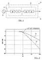
- FIG. 1is schematic representation of the pulsation attenuator of the preferred embodiment in a fluidic system with a fluidic pump.
- FIG. 2is a Bode magnitude plot of the first and second fluidic devices and the combination of the first and second fluidic devices.
- FIGS. 3 and 4are variations of the fluidic resistors.
- FIGS. 5 and 6are variations of the fluidic capacitors.
- the pulsation attenuator 10 of the preferred embodimentincludes a fluidic channel 12 , a first fluidic device 14 adapted to attenuate pulsations, and a second fluidic device 16 adapted to attenuate pulsations.
- the pulsation attenuator 10has been specifically designed for a fluidic system 18 of a flow cytometer with a fluidic pump 20 , such as a peristaltic pump, but may be alternatively used in any suitable fluidic system.
- the first fluidic device 14 and second fluidic device 16 of the preferred embodimentattenuate pulsations with a relatively shallow rolloff slope 22 .
- a shallow rolloff slopeis defined as less than or equal to 20 dB/decade (as conventionally understood in a Bode magnitude plot of log magnitude against log frequency, and as displayed as the absolute value of the slope).
- the first fluidic device 14 and the second fluidic device 16are connected to the fluidic channel 12 , however, such that they preferably cooperatively attenuate pulsations with a relatively steep rolloff slope 24 .
- a steep rolloff slope 24is defined as greater than 20 dB/decade (as conventionally understood in a Bode magnitude plot of log magnitude against log frequency, and as displayed as the absolute value of the slope).
- a steep rolloff slope 24such as greater than 20 dB/decade (or, more preferably, greater than or equal to 40 dB/decade)
- the pulsation attenuator 10may be able to pass low-frequency fluctuations of the flow rate and filter high-frequency pulsations of the fluid within the fluidic channel 12 . More significantly, the fluidic system may be able to rapidly adjust and stabilize the flow rate, while maintaining smooth flow.
- the rapid adjustment of the flow ratewhich may have previously took several minutes in conventional fluidic systems and now could potentially take seconds, preferably minimizes the waste of the fluid within the fluidic system.
- the cutoff frequencyis preferably less than or equal to 10 Hz and more preferably equal to 2 Hz, but may be any suitable cutoff frequency based on the needs of the fluidic system 18 .
- the fluidic channel 12 of the preferred embodimentfunctions to carry fluid, such as a sample fluid, in the fluidic system 18 .
- the fluid channelis preferably a rigid or flexible pipe, but may be any suitable fluidic device that carries fluid.
- the first fluidic device 14 and the second fluidic device 16 of the preferred embodimentfunction to attenuate pulsations.
- the term “pulsations”is defined as the periodic phenomenon that alternately increases and decreases either the pressure or flow rate of the fluid within the fluidic system.
- the first fluidic device 14preferably includes a first fluidic resistor 26 and a first fluidic capacitor 28
- the second fluidic device 16preferably includes a second fluidic resistor 30 and a second fluidic capacitor 32 .
- the first fluidic device 14 and the second fluidic device 16are preferably substantially similar.
- the first fluidic device 14 and the second fluidic device 16may be different fluidic devices and/or may have different fluidic values.
- the first fluidic resistor 26 and the second fluidic resistor 30function to resist the flow of the fluid within the fluidic channel 12 .
- the first fluidic resistor 26 and the second fluidic resistor 30are preferably a narrow-channel-type or a long-channel-type fluidic resistor 34 (which is shown in a space-saving serpentine-type arrangement in FIG. 3 ) or a ball-type fluidic resistor 36 (as shown in FIG. 4 ), but may be any suitable fluidic device to resist the flow of the fluid within the fluidic channel 12 .
- the first fluidic capacitor 28 and the second fluidic capacitor 32function to temporarily expand and accumulate fluid (and, hence, pressure) within the fluidic channel 12 and to later contract and reintroduce the accumulated fluid (and, hence, pressure) to the fluidic channel 12 .
- the first fluidic capacitor 28 and the second fluidic capacitor 32are preferably a bellows-type fluidic capacitor 38 (as shown in FIG. 5 ) or a flexible tube-type fluidic capacitor 40 (as shown in FIG. 6 ), but may be any suitable fluidic device to temporarily expand and later contract.
- the bellows-type fluidic capacitor 38may be made without an actual diaphragm between the fluid of the fluidic channel and the compressible fluid (such as air) of the bellows-type fluidic capacitor 38 . Instead of a diaphragm, the bellows-type fluidic capacitor 38 could rely on gravity or any other suitable method or device to keep the two fluids separate.
- the first fluidic device 14 and the second fluidic device 16are preferably configured and arranged to attenuate pulsations above a cutoff frequency (similar to an electronic low-pass filter). More specifically, the first fluidic device 14 includes the first fluidic resistor 26 followed by the first fluidic capacitor 28 , and the second fluidic device 16 includes the second fluidic resistor 30 followed by the second fluidic capacitor 32 .
- the fluid flowing through the pulsation attenuator 10encounters the following elements in this order: (1) the first fluidic resistor 26 , (2) the first fluidic capacitor 28 , (3) the second fluidic resistor 30 , and (4) the second fluidic capacitor 32 .
- the pulsation attenuator 10is similar to a second-order electronic low-pass filter with a rolloff slope of ⁇ 40 dB/decade.
- the pulsation attenuator 10may, alternatively, include more than two fluidic devices.
- a pulsation attenuator 10 that includes five fluidic devicesthe fluid encounters the following elements in this order: (1) the first fluidic resistor 26 , (2) the first fluidic capacitor 28 , (3) the second fluidic resistor 30 , (4) the second fluidic capacitor 32 , (5) a third fluidic resistor, (6) a third fluidic capacitor, (7) a fourth fluidic resistor, (8) a fourth fluidic capacitor, (9) a fifth fluidic resistor, and (10) a fifth fluidic capacitor.
- the pulsation attenuator 10is similar to a fifth-order electronic low-pass filter with a rolloff of ⁇ 100 dB/decade.
- the first fluidic device 14 and the second fluidic device 16may be alternatively configured and arranged to attenuate pulsations below a cutoff frequency (similar to an electronic high-pass filter).
- the pulsation attenuator 10 of alternative embodimentsmay be arranged in any suitable order and may have any suitable number of fluidic devices, fluidic resistors, and fluidic capacitors, including a combination of a “low-pass” pulsation attenuator and a “high-pass” pulsation attenuator that would either attenuate pulsations within two frequencies (similar to an electronic band-stop filter) or outside of two frequencies (similar to an electronic band-pass filter).
Landscapes
- Engineering & Computer Science (AREA)
- Mechanical Engineering (AREA)
- General Engineering & Computer Science (AREA)
- Physics & Mathematics (AREA)
- Fluid Mechanics (AREA)
- Chemical & Material Sciences (AREA)
- Analytical Chemistry (AREA)
- Reciprocating Pumps (AREA)
- Pipe Accessories (AREA)
Abstract
Description
Claims (26)
Priority Applications (8)
| Application Number | Priority Date | Filing Date | Title |
|---|---|---|---|
| US11/297,667US7328722B2 (en) | 2005-12-07 | 2005-12-07 | Pulsation attenuator for a fluidic system |
| ES06844858TES2454695T3 (en) | 2005-12-07 | 2006-12-06 | Pulsation attenuator for a fluidic system |
| EP20060844858EP1957853B1 (en) | 2005-12-07 | 2006-12-06 | Pulsation attenuator for a fluidic system |
| JP2008544456AJP2009518604A (en) | 2005-12-07 | 2006-12-06 | Pulsation attenuator for fluid system |
| PCT/US2006/046462WO2007067577A2 (en) | 2005-12-07 | 2006-12-06 | Pulsation attenuator for a fluidic system |
| CN2006800455509ACN101321983B (en) | 2005-12-07 | 2006-12-06 | Pulsation attenuators for fluidic systems |
| US11/958,278US7520300B2 (en) | 2005-12-07 | 2007-12-17 | Pulsation attenuator for a fluidic system |
| US12/425,830US7857005B2 (en) | 2005-12-07 | 2009-04-17 | Pulsation attenuator for a fluidic system |
Applications Claiming Priority (1)
| Application Number | Priority Date | Filing Date | Title |
|---|---|---|---|
| US11/297,667US7328722B2 (en) | 2005-12-07 | 2005-12-07 | Pulsation attenuator for a fluidic system |
Related Child Applications (1)
| Application Number | Title | Priority Date | Filing Date |
|---|---|---|---|
| US11/958,278ContinuationUS7520300B2 (en) | 2005-12-07 | 2007-12-17 | Pulsation attenuator for a fluidic system |
Publications (2)
| Publication Number | Publication Date |
|---|---|
| US20070125436A1 US20070125436A1 (en) | 2007-06-07 |
| US7328722B2true US7328722B2 (en) | 2008-02-12 |
Family
ID=38117537
Family Applications (2)
| Application Number | Title | Priority Date | Filing Date |
|---|---|---|---|
| US11/297,667Active2026-03-30US7328722B2 (en) | 2005-12-07 | 2005-12-07 | Pulsation attenuator for a fluidic system |
| US11/958,278ActiveUS7520300B2 (en) | 2005-12-07 | 2007-12-17 | Pulsation attenuator for a fluidic system |
Family Applications After (1)
| Application Number | Title | Priority Date | Filing Date |
|---|---|---|---|
| US11/958,278ActiveUS7520300B2 (en) | 2005-12-07 | 2007-12-17 | Pulsation attenuator for a fluidic system |
Country Status (6)
| Country | Link |
|---|---|
| US (2) | US7328722B2 (en) |
| EP (1) | EP1957853B1 (en) |
| JP (1) | JP2009518604A (en) |
| CN (1) | CN101321983B (en) |
| ES (1) | ES2454695T3 (en) |
| WO (1) | WO2007067577A2 (en) |
Cited By (18)
| Publication number | Priority date | Publication date | Assignee | Title |
|---|---|---|---|---|
| US20070212262A1 (en)* | 2006-03-08 | 2007-09-13 | Rich Collin A | Fluidic system for a flow cytometer |
| US20070243106A1 (en)* | 2006-04-17 | 2007-10-18 | Rich Collin A | Flow cytometer system with sheath and waste fluid measurement |
| US20080152542A1 (en)* | 2006-10-13 | 2008-06-26 | Ball Jack T | Fluidic system for a flow cytometer with temporal processing |
| US20090260701A1 (en)* | 2005-12-07 | 2009-10-22 | Rich Collin A | Pulsation attenuator for a fluidic system |
| US20100118298A1 (en)* | 2006-11-07 | 2010-05-13 | Bair Nathaniel C | Flow cell for a flow cytometer system |
| US20100319469A1 (en)* | 2005-10-13 | 2010-12-23 | Rich Collin A | Detection and fluidic system of a flow cytometer |
| US20100319786A1 (en)* | 2006-03-08 | 2010-12-23 | Bair Nathaniel C | Flow cytometer system with unclogging feature |
| US8283177B2 (en) | 2006-03-08 | 2012-10-09 | Accuri Cytometers, Inc. | Fluidic system with washing capabilities for a flow cytometer |
| US8432541B2 (en) | 2007-12-17 | 2013-04-30 | Accuri Cytometers, Inc. | Optical system for a flow cytometer with an interrogation zone |
| US8507279B2 (en) | 2009-06-02 | 2013-08-13 | Accuri Cytometers, Inc. | System and method of verification of a prepared sample for a flow cytometer |
| US9280635B2 (en) | 2010-10-25 | 2016-03-08 | Accuri Cytometers, Inc. | Systems and user interface for collecting a data set in a flow cytometer |
| US9551600B2 (en) | 2010-06-14 | 2017-01-24 | Accuri Cytometers, Inc. | System and method for creating a flow cytometer network |
| US20170248173A1 (en)* | 2009-01-22 | 2017-08-31 | Fte Automotive Gmbh | Device for reducing vibrations in a hydraulic actuating system, particularly hydraulic clutch actuating system for motor vehicles |
| US10022720B2 (en) | 2015-06-12 | 2018-07-17 | Cytochip Inc. | Fluidic units and cartridges for multi-analyte analysis |
| US10077999B2 (en) | 2015-07-14 | 2018-09-18 | Cytochip Inc. | Volume sensing in fluidic cartridge |
| WO2020036730A1 (en) | 2018-08-15 | 2020-02-20 | Becton, Dickinson And Company | Flowrate and vacuum controlled fluid management system for a flow type particle analyzer |
| US10634602B2 (en) | 2015-06-12 | 2020-04-28 | Cytochip Inc. | Fluidic cartridge for cytometry and additional analysis |
| US11491487B2 (en) | 2017-10-23 | 2022-11-08 | Cytochip Inc. | Devices and methods for measuring analytes and target particles |
Families Citing this family (9)
| Publication number | Priority date | Publication date | Assignee | Title |
|---|---|---|---|---|
| DE102016003717A1 (en)* | 2016-03-31 | 2017-10-05 | Fte Automotive Gmbh | Device for reducing vibrations in a hydraulic actuation system, in particular a hydraulic clutch actuation for motor vehicles |
| US8408242B2 (en)* | 2009-02-04 | 2013-04-02 | Edward S Chang | Overflow shutoff valve |
| US8528427B2 (en)* | 2010-10-29 | 2013-09-10 | Becton, Dickinson And Company | Dual feedback vacuum fluidics for a flow-type particle analyzer |
| CN103758798B (en)* | 2014-01-21 | 2016-01-20 | 华中科技大学 | Broad-frequency pressure-variable pressure pulsation attenuator |
| JP2018523114A (en)* | 2015-06-23 | 2018-08-16 | ナノセレクト バイオメディカル インコーポレイテッド | System, apparatus and method for cell sorting and flow cytometry |
| EP3338096B1 (en)* | 2015-08-24 | 2024-03-06 | Illumina, Inc. | In-line pressure accumulator and flow-control system for biological or chemical assays |
| WO2017116651A1 (en)* | 2015-12-30 | 2017-07-06 | Life Technologies Corporation | System and method for providing stable fluid flow |
| US20200011782A1 (en)* | 2017-03-31 | 2020-01-09 | Sony Corporation | Flow channel unit and microparticle analysis device |
| CN108547797B (en)* | 2018-03-21 | 2019-09-27 | 哈尔滨工程大学 | A kind of device inhibiting the pressure fluctuation of centrifugal pump jet source |
Citations (3)
| Publication number | Priority date | Publication date | Assignee | Title |
|---|---|---|---|---|
| US3672402A (en)* | 1970-09-14 | 1972-06-27 | Eaton Yale & Towne | Automatic precharge adjuster |
| US6039078A (en)* | 1989-09-22 | 2000-03-21 | Tamari; Yehuda | Inline extracorporeal reservoir and pressure isolator |
| US20020059959A1 (en)* | 2002-01-08 | 2002-05-23 | Qatu Mohamad S. | System and apparatus for noise suppression in a fluid line |
Family Cites Families (25)
| Publication number | Priority date | Publication date | Assignee | Title |
|---|---|---|---|---|
| US4448538A (en)* | 1982-04-06 | 1984-05-15 | Juval Mantel | Device for reducing static and dynamic pressures in pipelines, particularly of solid-borne sound in tubular conduits |
| JPS6353901U (en)* | 1986-09-26 | 1988-04-11 | ||
| US5040890A (en) | 1987-11-25 | 1991-08-20 | Becton, Dickinson And Company | Sheathed particle flow controlled by differential pressure |
| US4844610A (en) | 1988-04-29 | 1989-07-04 | Becton, Dickinson And Company | Backflow isolator and capture system |
| US5395588A (en)* | 1992-12-14 | 1995-03-07 | Becton Dickinson And Company | Control of flow cytometer having vacuum fluidics |
| JPH07260084A (en)* | 1994-03-16 | 1995-10-13 | Tokai Rubber Ind Ltd | Pulsation absorbing device |
| US6183697B1 (en) | 1997-05-27 | 2001-02-06 | Sysmex Corporation | Particle measuring apparatus |
| WO1999056052A1 (en)* | 1998-04-24 | 1999-11-04 | Hitachi Construction Machinery Co., Ltd. | Fluid pulsation reduction device |
| EP1046032A4 (en) | 1998-05-18 | 2002-05-29 | Univ Washington | CARTRIDGE FOR LIQUID ANALYSIS |
| US6110427A (en) | 1998-08-14 | 2000-08-29 | Becton, Dickinson And Company | Flow regulator to maintain controllable volumetric flow rate |
| JP3905291B2 (en)* | 1999-10-06 | 2007-04-18 | 株式会社ニデック | Ophthalmic perfusion suction device |
| EP1162449A1 (en)* | 2000-06-06 | 2001-12-12 | Universiteit Gent | AC-based gate detection method and device for the sizing of colloidal particles, cells and bacteria in liquids |
| CN1282834A (en)* | 2000-07-28 | 2001-02-07 | 王冲 | Method and equipment for depressurizing high-pressure fluid in flow channel and attenuating pulsed dynamic energy of fluid |
| US6382228B1 (en) | 2000-08-02 | 2002-05-07 | Honeywell International Inc. | Fluid driving system for flow cytometry |
| US7061595B2 (en) | 2000-08-02 | 2006-06-13 | Honeywell International Inc. | Miniaturized flow controller with closed loop regulation |
| US20020028434A1 (en) | 2000-09-06 | 2002-03-07 | Guava Technologies, Inc. | Particle or cell analyzer and method |
| JP2003262201A (en)* | 2002-03-08 | 2003-09-19 | Nok Corp | Accumulator |
| US6767188B2 (en)* | 2002-08-15 | 2004-07-27 | Becton, Dickinson And Company | Constant output fluidic system |
| US6825926B2 (en) | 2002-11-19 | 2004-11-30 | International Remote Imaging Systems, Inc. | Flow cell for urinalysis diagnostic system and method of making same |
| US6712096B1 (en)* | 2003-01-29 | 2004-03-30 | Kmt Waterjet Systems, Inc. | High pressure attenuator |
| KR101149880B1 (en) | 2003-08-13 | 2012-05-24 | 루미넥스 코포레이션 | Methods for controlling one or more parameters of a flow cytometer type measurement system |
| US7431883B2 (en) | 2003-09-30 | 2008-10-07 | Beckman Coulter, Inc. | Clinical analysis system |
| JP4027872B2 (en) | 2003-10-03 | 2007-12-26 | シスメックス株式会社 | Sheath flow forming apparatus and sample analyzing apparatus having the same |
| CA2607579A1 (en) | 2005-05-06 | 2006-11-23 | The Regents Of The University Of California | Microfluidic system for identifying or sizing individual particles passing through a channel |
| US8361410B2 (en) | 2005-07-01 | 2013-01-29 | Honeywell International Inc. | Flow metered analyzer |
- 2005
- 2005-12-07USUS11/297,667patent/US7328722B2/enactiveActive
- 2006
- 2006-12-06EPEP20060844858patent/EP1957853B1/enactiveActive
- 2006-12-06ESES06844858Tpatent/ES2454695T3/enactiveActive
- 2006-12-06WOPCT/US2006/046462patent/WO2007067577A2/enactiveApplication Filing
- 2006-12-06CNCN2006800455509Apatent/CN101321983B/enactiveActive
- 2006-12-06JPJP2008544456Apatent/JP2009518604A/enactivePending
- 2007
- 2007-12-17USUS11/958,278patent/US7520300B2/enactiveActive
Patent Citations (3)
| Publication number | Priority date | Publication date | Assignee | Title |
|---|---|---|---|---|
| US3672402A (en)* | 1970-09-14 | 1972-06-27 | Eaton Yale & Towne | Automatic precharge adjuster |
| US6039078A (en)* | 1989-09-22 | 2000-03-21 | Tamari; Yehuda | Inline extracorporeal reservoir and pressure isolator |
| US20020059959A1 (en)* | 2002-01-08 | 2002-05-23 | Qatu Mohamad S. | System and apparatus for noise suppression in a fluid line |
Cited By (34)
| Publication number | Priority date | Publication date | Assignee | Title |
|---|---|---|---|---|
| US8470246B2 (en) | 2005-10-13 | 2013-06-25 | Accuri Cytometers, Inc. | Detection and fluidic system of a flow cytometer |
| US8303894B2 (en) | 2005-10-13 | 2012-11-06 | Accuri Cytometers, Inc. | Detection and fluidic system of a flow cytometer |
| US20100319469A1 (en)* | 2005-10-13 | 2010-12-23 | Rich Collin A | Detection and fluidic system of a flow cytometer |
| US20090260701A1 (en)* | 2005-12-07 | 2009-10-22 | Rich Collin A | Pulsation attenuator for a fluidic system |
| US7857005B2 (en) | 2005-12-07 | 2010-12-28 | Accuri Cytometers, Inc. | Pulsation attenuator for a fluidic system |
| US8262990B2 (en) | 2006-03-08 | 2012-09-11 | Accuri Cytometers, Inc. | Flow cytometer system with unclogging feature |
| US8283177B2 (en) | 2006-03-08 | 2012-10-09 | Accuri Cytometers, Inc. | Fluidic system with washing capabilities for a flow cytometer |
| US20100319786A1 (en)* | 2006-03-08 | 2010-12-23 | Bair Nathaniel C | Flow cytometer system with unclogging feature |
| US20070212262A1 (en)* | 2006-03-08 | 2007-09-13 | Rich Collin A | Fluidic system for a flow cytometer |
| US8017402B2 (en) | 2006-03-08 | 2011-09-13 | Accuri Cytometers, Inc. | Fluidic system for a flow cytometer |
| US8187888B2 (en) | 2006-03-08 | 2012-05-29 | Accuri Cytometers, Inc. | Fluidic system for a flow cytometer |
| US7981661B2 (en) | 2006-04-17 | 2011-07-19 | Accuri Cytometers, Inc. | Flow cytometer system with sheath and waste fluid measurement |
| US20070243106A1 (en)* | 2006-04-17 | 2007-10-18 | Rich Collin A | Flow cytometer system with sheath and waste fluid measurement |
| US20080152542A1 (en)* | 2006-10-13 | 2008-06-26 | Ball Jack T | Fluidic system for a flow cytometer with temporal processing |
| US8715573B2 (en) | 2006-10-13 | 2014-05-06 | Accuri Cytometers, Inc. | Fluidic system for a flow cytometer with temporal processing |
| US8445286B2 (en) | 2006-11-07 | 2013-05-21 | Accuri Cytometers, Inc. | Flow cell for a flow cytometer system |
| US20100118298A1 (en)* | 2006-11-07 | 2010-05-13 | Bair Nathaniel C | Flow cell for a flow cytometer system |
| US8432541B2 (en) | 2007-12-17 | 2013-04-30 | Accuri Cytometers, Inc. | Optical system for a flow cytometer with an interrogation zone |
| US20170248173A1 (en)* | 2009-01-22 | 2017-08-31 | Fte Automotive Gmbh | Device for reducing vibrations in a hydraulic actuating system, particularly hydraulic clutch actuating system for motor vehicles |
| US10288093B2 (en)* | 2009-01-22 | 2019-05-14 | Fte Automotive Gmbh | Device for reducing vibrations in a hydraulic actuating system, particularly hydraulic clutch actuating system for motor vehicles |
| US8507279B2 (en) | 2009-06-02 | 2013-08-13 | Accuri Cytometers, Inc. | System and method of verification of a prepared sample for a flow cytometer |
| US9523677B2 (en) | 2009-06-02 | 2016-12-20 | Accuri Cytometers, Inc. | System and method of verification of a prepared sample for a flow cytometer |
| US9551600B2 (en) | 2010-06-14 | 2017-01-24 | Accuri Cytometers, Inc. | System and method for creating a flow cytometer network |
| US10481074B2 (en) | 2010-10-25 | 2019-11-19 | Becton, Dickinson And Company | Systems and user interface for collecting a data set in a flow cytometer |
| US10031064B2 (en) | 2010-10-25 | 2018-07-24 | Accuri Cytometers, Inc. | Systems and user interface for collecting a data set in a flow cytometer |
| US9280635B2 (en) | 2010-10-25 | 2016-03-08 | Accuri Cytometers, Inc. | Systems and user interface for collecting a data set in a flow cytometer |
| US11125674B2 (en) | 2010-10-25 | 2021-09-21 | Becton, Dickinson And Company | Systems and user interface for collecting a data set in a flow cytometer |
| US10022720B2 (en) | 2015-06-12 | 2018-07-17 | Cytochip Inc. | Fluidic units and cartridges for multi-analyte analysis |
| US10634602B2 (en) | 2015-06-12 | 2020-04-28 | Cytochip Inc. | Fluidic cartridge for cytometry and additional analysis |
| US10967374B2 (en) | 2015-06-12 | 2021-04-06 | Cytochip Inc. | Methods of analyzing biological samples using a fluidic cartridge |
| US12025550B2 (en) | 2015-06-12 | 2024-07-02 | Cytochip Inc. | Fluidic cartridge for cytometry and additional analysis |
| US10077999B2 (en) | 2015-07-14 | 2018-09-18 | Cytochip Inc. | Volume sensing in fluidic cartridge |
| US11491487B2 (en) | 2017-10-23 | 2022-11-08 | Cytochip Inc. | Devices and methods for measuring analytes and target particles |
| WO2020036730A1 (en) | 2018-08-15 | 2020-02-20 | Becton, Dickinson And Company | Flowrate and vacuum controlled fluid management system for a flow type particle analyzer |
Also Published As
| Publication number | Publication date |
|---|---|
| EP1957853A2 (en) | 2008-08-20 |
| EP1957853B1 (en) | 2014-02-12 |
| CN101321983B (en) | 2011-03-23 |
| CN101321983A (en) | 2008-12-10 |
| US20070125436A1 (en) | 2007-06-07 |
| WO2007067577A3 (en) | 2008-01-17 |
| US20080156379A1 (en) | 2008-07-03 |
| EP1957853A4 (en) | 2011-01-26 |
| ES2454695T3 (en) | 2014-04-11 |
| WO2007067577A2 (en) | 2007-06-14 |
| US7520300B2 (en) | 2009-04-21 |
| JP2009518604A (en) | 2009-05-07 |
Similar Documents
| Publication | Publication Date | Title |
|---|---|---|
| US7328722B2 (en) | Pulsation attenuator for a fluidic system | |
| US7857005B2 (en) | Pulsation attenuator for a fluidic system | |
| US11603836B2 (en) | Microfluidic pump-based infusion anomaly state detection and control system | |
| US8561470B2 (en) | Apparatus and method for eliminating varying pressure fluctuations in a pressure transducer | |
| AU2019232735B2 (en) | Devices and methods for managing chest drainage | |
| CN101493102B (en) | Pressure sensing device adapted to corrosive or explosive atmospheres and with means to filter disturbance frequencies | |
| US20170328801A1 (en) | Tunable pressure transducer assembly | |
| EP4458450A3 (en) | Monitoring devices for air filtration systems | |
| US20240230390A9 (en) | Volumetric measurement device, system and method | |
| CN204610440U (en) | Multistage return filter and pressure test device thereof | |
| CN106404272A (en) | High-pressure infusion pump pressure buffer sensor and pressure buffer method | |
| WO2007011223A3 (en) | Filter device for filtering a hydraulic fluid. | |
| CN208700643U (en) | The adaptive clean water control system of more water quality | |
| EP2757072A1 (en) | Fluid shunt system | |
| US20160339366A1 (en) | Fluid filtering device | |
| CN208605316U (en) | Metering pump assembly | |
| GB2561131A (en) | Strainer with pressure indicator | |
| EP3218632A1 (en) | Device for dampening pressure pulsations in a gas flow |
Legal Events
| Date | Code | Title | Description |
|---|---|---|---|
| AS | Assignment | Owner name:ACCURI INSTRUMENTS, INC., MICHIGAN Free format text:ASSIGNMENT OF ASSIGNORS INTEREST;ASSIGNORS:RICH, COLLIN A.;MARTIN, STEVEN M.;REEL/FRAME:017340/0121 Effective date:20051207 | |
| AS | Assignment | Owner name:ACCURI CYTOMETERS, INC., MICHIGAN Free format text:CHANGE OF NAME;ASSIGNOR:ACCURI INSTRUMENTS, INC.;REEL/FRAME:019659/0157 Effective date:20070412 | |
| AS | Assignment | Owner name:VENTURE LENDING & LEASING IV, INC. AND VENTURE LEN Free format text:SECURITY AGREEMENT;ASSIGNOR:ACCURI CYTOMETERS, INC.;REEL/FRAME:019913/0721 Effective date:20070919 | |
| STCF | Information on status: patent grant | Free format text:PATENTED CASE | |
| FPAY | Fee payment | Year of fee payment:4 | |
| FEPP | Fee payment procedure | Free format text:PAT HOLDER NO LONGER CLAIMS SMALL ENTITY STATUS, ENTITY STATUS SET TO UNDISCOUNTED (ORIGINAL EVENT CODE: STOL); ENTITY STATUS OF PATENT OWNER: LARGE ENTITY | |
| FPAY | Fee payment | Year of fee payment:8 | |
| MAFP | Maintenance fee payment | Free format text:PAYMENT OF MAINTENANCE FEE, 12TH YEAR, LARGE ENTITY (ORIGINAL EVENT CODE: M1553); ENTITY STATUS OF PATENT OWNER: LARGE ENTITY Year of fee payment:12 |