US7327959B2 - Camera-mountable fiber optic transceiver system - Google Patents
Camera-mountable fiber optic transceiver systemDownload PDFInfo
- Publication number
- US7327959B2 US7327959B2US10/023,452US2345201AUS7327959B2US 7327959 B2US7327959 B2US 7327959B2US 2345201 AUS2345201 AUS 2345201AUS 7327959 B2US7327959 B2US 7327959B2
- Authority
- US
- United States
- Prior art keywords
- transceiver
- signal
- signals
- camera
- input
- Prior art date
- Legal status (The legal status is an assumption and is not a legal conclusion. Google has not performed a legal analysis and makes no representation as to the accuracy of the status listed.)
- Expired - Lifetime, expires
Links
- 239000000835fiberSubstances0.000titleclaimsabstractdescription44
- 230000003287optical effectEffects0.000claimsabstractdescription68
- 238000004519manufacturing processMethods0.000claimsabstractdescription24
- 230000005236sound signalEffects0.000claimsdescription11
- 230000007175bidirectional communicationEffects0.000claims1
- 230000013011matingEffects0.000claims1
- 238000011144upstream manufacturingMethods0.000abstractdescription6
- 230000005540biological transmissionEffects0.000description11
- 238000010586diagramMethods0.000description9
- RYGMFSIKBFXOCR-UHFFFAOYSA-NCopperChemical compound[Cu]RYGMFSIKBFXOCR-UHFFFAOYSA-N0.000description8
- 229910052802copperInorganic materials0.000description8
- 239000010949copperSubstances0.000description8
- 230000008901benefitEffects0.000description6
- 239000013307optical fiberSubstances0.000description5
- 239000002131composite materialSubstances0.000description4
- 238000000034methodMethods0.000description4
- 230000003321amplificationEffects0.000description2
- 239000000203mixtureSubstances0.000description2
- 238000003199nucleic acid amplification methodMethods0.000description2
- 230000009471actionEffects0.000description1
- 238000006243chemical reactionMethods0.000description1
- 239000004020conductorSubstances0.000description1
- 230000008878couplingEffects0.000description1
- 238000010168coupling processMethods0.000description1
- 238000005859coupling reactionMethods0.000description1
- 229910052737goldInorganic materials0.000description1
- 239000010931goldSubstances0.000description1
- 238000003780insertionMethods0.000description1
- 230000037431insertionEffects0.000description1
- 230000008569processEffects0.000description1
- 230000008439repair processEffects0.000description1
- 238000010079rubber tappingMethods0.000description1
Images


Classifications
- H—ELECTRICITY
- H04—ELECTRIC COMMUNICATION TECHNIQUE
- H04B—TRANSMISSION
- H04B10/00—Transmission systems employing electromagnetic waves other than radio-waves, e.g. infrared, visible or ultraviolet light, or employing corpuscular radiation, e.g. quantum communication
- H04B10/40—Transceivers
- H—ELECTRICITY
- H04—ELECTRIC COMMUNICATION TECHNIQUE
- H04N—PICTORIAL COMMUNICATION, e.g. TELEVISION
- H04N23/00—Cameras or camera modules comprising electronic image sensors; Control thereof
- H04N23/60—Control of cameras or camera modules
- H04N23/66—Remote control of cameras or camera parts, e.g. by remote control devices
Definitions
- ENG/SNGelectronic news gathering/satellite news gathering
- EFPelectronic field production
- OBoutside broadcast
- ENG/SNG applicationstypically feature a single camera with a built-in video tape recorder (VTR) which is most often used as a stand-alone camcorder for recording live events locally to tape.
- FIG. 1shows a prior art camera system 12 . This camera can also serve as a “live” camera from the scene of the news event. At that point, it is commonly connected to a video production vehicle control center 11 via either copper cables or coaxial cables 17 .
- the camerais connected to the truck with multiple copper cables which typically include one-to-three coax cables with BNC connectors for video signals and one-to-four shielded twisted audio pairs with XLR connectors for audio and intercom signals as well as power if the camera is not powered by a local battery.
- multiple copper cablestypically include one-to-three coax cables with BNC connectors for video signals and one-to-four shielded twisted audio pairs with XLR connectors for audio and intercom signals as well as power if the camera is not powered by a local battery.
- BNC connectorsfor video signals
- XLR connectorsfor audio and intercom signals
- U.S. Pat. No. 5,345,592discloses such a system.
- Multicoreis a 26-conductor cable that carries power and all of the required signals over discreet copper wires. Multicore is limited in distance, and is heavy, inflexible, expensive, and hard to repair in the field.
- Outside Broadcastfeatures multiple cameras (three or more) serviced by cameras with triaxial capability.
- This applicationincludes sports, live music concerts, scripted programs shot outside of studios, and other shows where large crews shoot action that is confined within a prescribed area and is fairly predictable.
- the OB cameracan be remotely controlled and powered from a local or distant camera control unit (CCU), sometimes called a base station, through a transmission medium known as triaxial cable.
- CCUcamera control unit
- the triaxial adapterdemodulates the composite signal at either of the receiving ends of the triaxial cable into the respective baseband signals.
- the triaxial adaptermay be contained within the camera and/or CCU ends, or may be separate units that attach to the camera and/or CCU ends.
- the effective distance over which the camera and CCU can communicate and operateis limited to one to three kilometers.
- a trend in the industryhas been towards cameras having higher performance and wider information bandwidths, thus further limiting the distance of a wideband, component triaxial camera system to approximately one kilometer.
- usersmay utilize a larger, heavier cable, which may increase distance, but also increases time and labor to deploy and take up the cable. This distance limitation often interferes with the user's ability to produce the desired programming.
- Some camera manufacturersprovide a fiber optic interface directly on the camera and on the CCU.
- these solutionscan require significant investments in new cameras, CCUs and supporting infrastructure.
- Video cameras for ENG or EFP applicationstypically are equipped with a specialized battery mount that provides a rugged, secure and reliable attachment of the battery to the camera.
- Known systems for battery mountinginclude Anton/Bauer, PAG, and Sony V-mount.
- the above and other problemsare solved by the camera-mountable fiber optic transceiver system of the present approach.
- the systemincludes a multiplexing transceiver which is adapted to mount directly between a video camera and a camera battery pack, eliminating the need for triaxial adapters or other electrical cables at the camera and remote equipment.
- a fiber optic cablecarries upstream and downstream television signals between the camera-mountable transceiver and a remote base station transceiver.
- Fiber optic cablecombines the advantages of increasing distance with smaller, lightweight cabling. Fiber optic cable eliminates all types of electromagnetic and radio frequency interference as well as ground faults and hum. With transparency, bandwidth and small cable size, the present system can deliver television signals at thirty times the distance of ordinary coaxial or triaxial cable type systems.
- a transceiver of the present systemprovides an interface between a camera and a fiber optic cable.
- the transceiverincludes a transmitter adapted for converting an electrical information input signal received from the camera to an optical output signal.
- the transceiverfurther includes a receiver adapted for converting an optical input signal received from the fiber optic cable to an electrical information output signal.
- the electrical information signalscan include video, audio and data signals.
- a housing that holds the transmitter and receiveris adapted for mounting to the camera.
- the housingincludes a first plate on a first side for mounting the housing to the camera, and a second plate on a second side for mounting the housing to a battery or other power source. Power is passed from the battery to the camera through the housing, and tapped off to power the transceiver.
- the plates for mounting the housingare compatible with standard battery mounts which avoids the need to modify the cameras to support the transceiver.
- the transmitterincludes a multiplexer for multiplexing plural camera information signals to a multiplexed electrical input signal and an electrical-to-optical converter for converting the multiplexed electrical input signal to the optical output signal.
- a systemincludes a camera-mountable optical transceiver for transmitting a downstream optical signal and for receiving an upstream optical signal; a remote optical transceiver for transmitting the upstream optical signal and for receiving the downstream optical signal; and a fiber optic cable coupled between the camera-mountable optical transceiver and the remote optical transceiver for carrying the downstream and upstream optical signals.
- the camera-mountable optical transceiverincludes a housing for mounting to the camera.
- the present systemhas particular applicability for ENG, SNG and other events where the events themselves may be some distance from the production base station.
- the present systemfurther saves time and labor in arranging outside broadcast events.
- Use of fiber optic cablescan eliminate more than 90% of the typical cable weight of copper cables.
- the systemcan also be used in metropolitan applications, directly linking remote venues to production studio via leased “dark fiber” (replacing microwave links), and in pre-fibered venues and campuses, avoiding the need to pull copper cables.
- FIG. 1is a diagram of a prior art camera control system.
- FIG. 2Ais a diagram of another prior art camera control system.
- FIG. 2Bis a diagram of a fiber optic triaxial camera control system.
- FIG. 3Ais a diagram of a camera-mountable fiber optic transceiver system of the present approach.
- FIG. 3Bshows the type of signals carried by the system of FIG. 3A .
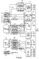
- FIGS. 4A and 4Bare block diagrams of an embodiment of the camera transceiver unit of the system of FIG. 3A .
- FIGS. 5A and 5Bare block diagrams of an embodiment of the base station transceiver unit of the system of FIG. 3A .
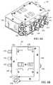
- FIG. 6Ais a perspective view of an embodiment of a housing for the camera transceiver unit.
- FIG. 6Bis a right side view of the housing of FIG. 6A .
- FIG. 7illustrates a partially exploded view of a configuration for mounting the camera transceiver unit between a camera and a battery system.
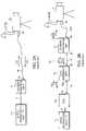
- FIG. 2AA prior art camera control system is shown in FIG. 2A .
- the systemincludes a camera control unit (CCU) 10 linked to a camera 12 using a cable 14 .
- the CCU 10 and the camera 12each include a connector 16 , 18 respectively for coupling television program signals to the cable 14 .
- the CCU 10transmits program signal CU and the camera 12 originates program signal CA.
- the signals CU and CAmay include, for example, program video, return video, viewfinder video, gen-lock, intercom and other audio program signals.
- the cable 14can be copper, coaxial, triaxial or multicore type.
- the CCU 10connects the multiple signals CU, CA over multiple cables 17 to a video production facility 11 .
- a camera control panel(not shown) may also be included, either integral with the CCU 10 , or more commonly, mounted separately and connected to the CCU.
- the electrical signals CA and CUare conventional television signals typically arranged in a frequency division multiplex (FDM) format of the individual video, audio, and control signals which in aggregate have a typical bandpass of about 100 MHz.
- FDMfrequency division multiplex
- FIG. 2Bshows a fiber optic triaxial camera control system 20 such as that disclosed in U.S. Pat. No. 6,115,159, the contents of which are incorporated herein by reference.
- the system 20generally comprises a camera control interface unit 22 , a camera interface unit 24 , and a fiber optic cable 30 .
- the control interface unit 22is linked to CCU 10 using a section of standard triaxial cable 14 A.
- the camera interface unit 24is linked to camera 12 using a triaxial cable section 14 B.
- multiple signals CU, CAare connected between the CCU 10 and the video production facility over multiple cables 17 .
- the control interface unit 22 and the camera interface unit 24each provide an electro/optical and opto/electrical conversion function.
- the control interface unit 22converts FDM signal CU received on triaxial cable 14 A to provide optical signal OCU on fiber optic cable 30 .
- the optical signal OCUis transmitted on fiber optic cable 30 to the camera interface unit 24 where it is converted back to electrical FDM signal CU and coupled to the triaxial cable 14 B and passed to camera 12 .
- the camera interface unit 24converts FDM signal CA received from the camera 12 on triaxial cable 14 B to provide optical signal OCA which is transmitted on fiber optic cable 30 to the control interface unit 22 .
- the control interface unit 22converts the optical signal OCA back to electrical FDM signal CA for transmission to the CCU 10 on triaxial cable 14 A.
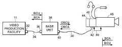
- FIG. 3Ashows a diagram of a system of the present approach that includes a camera transceiver unit 46 and a base station transceiver unit 38 .
- the camera transceiver unitis mounted between a camera 48 and a battery or other power supply 44 .
- the base station transceiver unitis coupled to a remote video production facility 11 .
- the camera transceiver unitis connected to the base station transceiver unit by a fiber optic cable 30 .
- the fiber optic cableis multimode or single mode optical fiber.
- baseband television signals designated BCAoriginate from the camera 48 and are coupled to the camera transceiver unit 46 via cables 50 .
- the electrical signals BCAare converted to optical signal OBCA for transmission downstream on fiber optic cable 30 to the base station transceiver unit 38 .
- the base station transceiver unit 38converts baseband television signals designated BCU originated from the video production facility 11 .
- the BCU and BCA signalsare carried between the video production facility 11 and the base unit 38 over multiple cables designated 34 .
- the BCU signalsare converted to optical signal OBCU which is carried upstream on fiber optic cable 30 .
- the signalsare shown in FIG. 3B . It should be understood that the principles of the present approach also apply to embodiments that do not include camera control equipment.
- the camera transceiver unitis housed in a housing that has plates on opposite sides that allow the housing to be mounted between a battery and camera.
- the camera transceiver unitconnects camera signals on a 12 pin connector 170 .
- the camera signalsinclude camera video in 172 ; return video out 176 ; audio 1 (camera) in 180 ; tally relay contacts 182 and headset trigger signal 183 .
- the return video out signal 176is coupled to a return video out BNC connector 164 .
- Additional signals from the camerainclude a black burst out signal 178 coupled to BNC connector 168 , an auxiliary video in BNC connector signal 162 , headset signals 118 A, 118 B on XLR connector 118 , return audio out XLR signal 116 and an audio 2 input XLR signal 114 .
- a 10 pin connector 184provides additional signals to and from the camera. These remote signals include camera remote control input 186 , camera remote control output 190 , RS232 input 192 , RS232 output 194 , and a nominal 12 volt DC power signal 196 . In addition, a camera remote control format control signal 188 is provided, the function of which is described in further detail below.
- the camera unitreceives a nominal 12 volt battery input signal 195 from a 12 volt battery pack that is connected to the housing of the camera unit as described further below.
- An auto-select circuit 198selects between 12 VDC power signal 196 from the camera and the 12 VDC battery signal 195 to supply a power supply 156 that distributes power via distribution lines 156 A.
- Power loop through 191connects the 12 VDC battery signal 195 through to the camera from the battery.
- the camera video in signal 172is coupled to an anti-alias filter 174 which removes extraneous signals from the camera video input.
- the auxiliary video in signal 162is filtered via anti-alias filter 166 .
- the filtered video signalsare input to a video auto-select circuit 134 .
- the video auto-select circuitselects between the auxiliary video and the program video signals to provide one of the signals for transmission to the base station unit.
- the selected video signalis coupled to an off-set cancellation circuit 136 which removes DC off-set in the video signal.
- the output of the off-set cancellation circuit 136is input to a 12 bit video analog-to-digital (A/D) converter 138 .
- the video A/D converter circuit 138samples the composite video signal at 31.1040 mega samples per second with 12 bits per sample.
- the audio input signals 114 , 118 A and 180are amplified in amplifier circuit 120 .
- input level select circuit 110provides user-selectable gains of 40 dB and 60 dB for a microphone input or unity gain for line level input.
- the amplified audio signalsare connected to a pair of stereo audio A/D converter circuits 122 .
- the audio A/D converter circuit 122provides 24 bit samples that are sampled at the rate of 48.6 kilo samples per second.
- the outputs of the audio A/D converter circuit 122include a serialized data signal that includes left and right stereo samples, and a left/right indicator signal.
- Audio 1 signal 180uses the left channel of one of the stereo A/D converter circuits 122 .
- the headset signal 118uses the right channel of the first audio A/D circuit.
- the audio 2 signalis coupled to the second stereo audio A/D converter.
- the digital output 161 of the 12 bit video A/D converter circuit 138 and the digital output 159 of the 24 bit audio A/D converter circuits 122are coupled to a multiplexer 124 .
- the multiplexermultiplexes the signals at a rate of 31.1040 mega words per second resulting in an aggregate bit rate of 622.080 megabits per second.
- the multiplexer 124is a HDMP-1032 multiplexer provided by Hewlett Packard. Additional data inputs to the multiplexer 124 include data signals 157 from remote signal connector 184 .
- the output of the multiplexer 124is a serial bit stream that is connected to a laser diode driver circuit 132 .
- the laser driver circuitdrives a laser diode.
- the laser diode 132may be coupled to a wavelength division multiplexer (WDM) 140 .
- the optical signal OBCA produced by the laser diodeis at a first wavelength ⁇ 1 , such as 1310 nm.
- the optical signal OBCU from the base station transceiver unit 38 ( FIG. 3A )is received at port 42 and may be coupled via the WDM 140 .
- the optical signal OBCUis at a second wavelength ⁇ 2 , such as 1550 nm.
- the optical wavelengthsare preferably selected from wavelengths in the range of 1300 nm to 1550 nm.
- the WDM 140splits the optical signals ⁇ 1 and ⁇ 2 .
- wavelength division multiplexingto provide transmission of optical signals OBCU and OBCA on a single optical fiber
- other embodiments of the inventioncan have a separate optical fiber for each direction of transmission.
- the wavelength division multiplexingis not employed, and ⁇ 1 can be the same as ⁇ 2 .
- an optical signal at 1550 nanometersis received on the fiber port 42 .
- This receive optical signalis coupled to an optical pre-amp stage 150 which provides optical amplification to bring the signal to a useful level.
- the optical pre-amp circuit 150also includes an optical/electrical converter the output of which is provided to a demultiplexer 154 .
- the digital output of the demultiplexer 154includes digital video signals 151 , 149 , data signals 153 and audio signal 155 .
- the demultiplexer 154is a HDMP-1034 multiplexer provided by Hewlett Packard.
- Video signal 149is coupled to a 1:2 video data demultiplexer 148 .
- the 1:2 demultiplexerdecodes data for the return video that is sampled at half the data rate to use only 4 bits on a corresponding multiplexer at the base station unit 38 ( FIG. 3A ) as described further herein.
- the decoded video output from the 1:2 demultiplexer 148 and the digital video signal 151are 8 bit sample signals that are converted to baseband analog video signals by video D/A converters 146 A, 146 B.
- the video D/A converter 146 Aoperates at 15.5520 mega samples per second; the video D/A converter 146 B operates at 31.1040 mega samples per second.
- the baseband analog video signalsare filtered by filters 145 , 147 and amplified by amplifier block 144 to provide return video out signal 176 and black burst out signal 178 .
- the audio signal 155is provided to an AES/EBU demultiplexer circuit 130 which takes serial data from the demultiplexer 154 and converts that serial data into 24 bit sample signals coupled to audio digital-to-analog (D/A) converter circuit 128 .
- the AES/EBU demultiplexeris used to simplify the decoding of the signals by the D/A converter 128 .
- the audio D/A converter 128operates at 48.6 kilo samples per second.
- the baseband analog audio signals output from the audio D/A converter 128are amplified by amplifier block 126 to provide output audio signals 116 , 118 B.
- the remote signalsinclude a camera remote control input and a camera remote control output signal 186 , 190 .
- the camera remote control signalscan take on formats that include a bi-directional 2-wire format, RS422, and RS232 format.
- a format control signal 187is included in the cable received from the camera in the 10 pin connector 184 .
- a particular cableis pre-made to select a particular format.
- the selected formatis indicated by having one of the pins in the 10 pin connector coupled to ground, 12 volts or left open.
- the pin stateis interpreted by camera remote control format control circuit 188 .
- An auxiliary data I/O functions block 152provides input amplifiers for the different data types for camera remote control input 186 and 232 input 192 .
- the data I/O blockalso provides output levels for the proper data types for 232 output 194 and camera remote control output 190 .
- the main system clockis derived from the camera system clock 158 ( FIG. 4B ) which supplies all the clocks for the system. From the data that is received at the base station unit, the base station unit recovers that same clock and uses it as its transmission medium for the data that returns back to the camera unit. Recovered receiver section system clock 160 ( FIG. 4B ) uses a clock recovered from the base station unit to provide clock to the received side functions in the camera unit.
- the base station transceiver unit 38provides similar electro-optical functionality to the camera transceiver unit 46 ( FIG. 3A ).
- signals between the video production facility 11 and the base station transceiver unit 38correspond to signals carried to and from the camera transceiver unit 46 on the fiber optic cable 30 .
- Baseband analog signals received from the video production facility 11include return video in 212 , black burst in 214 , return audio in 206 and headset signal 208 B on XLR connector 208 .
- the video production facility 11receives baseband analog signals from the base station transceiver unit that include program/auxiliary video out 210 , audio 1 out 202 , audio 2 out 204 and headset signal 208 A on XLR connector 208 .
- Additional signals between the video production facility 11 and the base station transceiver unitinclude tally signal 226 and RS232 data input/output signals 228 , 230 through 9 pin D type connector 216 , and camera remote control input/output data signals 232 , 236 with program signal 233 on data port 9 pin D type connector 218 .
- the base station transceiver unitreceives a DC input power signal 220 that connects to a power supply 254 .
- the power supplyalso receives an input from an internal battery line 238 and distributes power to lines 254 A.
- the return video in 212 and black burst in 214 signalsare coupled to respective anti-alias filters 222 , 224 to remove extraneous signals from the video signals.
- the filtered video signalsare amplified in amplifier block 250 which can also include a dither insertion function.
- a dither signalthat generally comprises a filtered noise source can be applied to the analog video signal as a means to integrate the steps resulting from the digitizing process.
- the noiseis “shaped” (filtered) so as not to interfere with the analog signal being digitized.
- the amplified black burst signalis input to an 8 bit video A/D converter 264 which samples at 31.1040 mega samples per second to provide digital data output signal 269 .
- the amplified return video signalis input to an 8 bit video A/D converter 262 which samples the signal at 15.5520 mega samples per second, half the rate of A/D converter 264 .
- the output of A/D converter 262is multiplexed in 2:1 video data multiplexer 268 to provide a digital data output signal 267 .
- the audio input signals 206 , 208 plus a sidetone mix signal 242are amplified in amplifier circuit 246 .
- the amplified audio signalsare connected to 24 bit audio A/D converter circuit 258 operating at 48.6 kilo samples per second.
- An AES/EBU multiplexer 266receives signals output from the audio A/D converter 258 and multiplexes them together into one serial stream 265 to simplify the transmission of the data.
- the AES/EBU multiplexer 266includes user bits in addition to audio data inputs.
- the tally signal 226can be carried as one of the user bits.
- An auxiliary data I/O functions block 252provides input amplifiers for the different data types for camera remote control input 232 and RS232 input 228 .
- the data I/O blockalso provides output levels for the proper data types for RS232 output 230 and camera remote control output 236 .
- the encoded digital audio signal 265is multiplexed together with digital video data outputs 267 , 269 and data signals 271 in a multiplexer 276 .
- the multiplexer 276operates at a rate of 31.1040 mega words per second resulting in an aggregate bit rate of 622.080 mega bits per second.
- the output of the multiplexer 276is a serial bit stream that is connected to a laser diode driver circuit 278 that drives a laser diode coupled to a WDM 280 .
- the optical signal OBCU produced by the laser diodeis at wavelength ⁇ 2 , such as 1550 nm.
- the optical signal OBCA from the camera transceiver unit 46( FIG. 3A ) is received at port 40 and may be coupled via the WDM 280 .
- the optical signal OBCAis at wavelength ⁇ 1 , such as 1310 nm.
- the WDM 280splits the optical signals ⁇ 1 and ⁇ 2 .
- an optical signal at 1310 nanometersis received on the fiber port 40 .
- This receive optical signalis coupled to an optical pre-amp stage 284 which provides optical amplification to bring the signal to a useful level.
- the optical pre-amp circuit 284also includes an optical/electrical converter the output of which is provided to a demultiplexer 286 .
- the digital output of the demultiplexer 286includes digital audio signal 257 , digital video signal 259 and data signal 261 .
- the digital audio signal 257is provided to two 24 bit audio D/A converters 256 which converts the signal 257 to provide analog audio 1 signal 202 , audio 2 signal 204 and headset signal 208 A.
- An amplifier circuit 244provides gain for these audio output signals and provides the sidetone mix signal 242 .
- the digital video signal 259is coupled to a 12 bit video D/A converter 260 that operates at 31.1040 mega samples per second.
- the baseband analog video output from the D/A converter 260is filtered by filter 249 and amplified by amplifier block 248 to provide program/auxiliary video output signal 210 .
- the data signal 261is coupled to the auxiliary data I/O block 252 to provide the proper levels to the video production facility 11 ( FIG. 3A ).
- system clock for the base unitis provided by local clock 270 .
- the base unitrecovers clock from the data received from the camera transceiver unit and subsequently the base unit switches from the local clock 270 to recovered clock 272 using an auto select circuit 274 .
- FIG. 6Ashows a perspective view of an embodiment of a housing 302 for the camera transceiver unit 46 .
- FIG. 6Bshows a right side view of the housing.
- a front panel 350 of the housingincludes BNC connectors 312 , 314 , 316 ; XLR connectors 318 , 320 , 322 ; Hirose connectors 324 , 326 .
- Other connector arrangementsare possible and the particular configuration is shown for illustration purposes only.
- An ST type or other type fiber cable receptacle 328is positioned at a 45 degrees angle below the front panel. Rails 330 protect the fiber cable receptacle.
- a left side 304 of the housingincludes a mounting plate 306 ( FIG. 6A ).
- a second mounting plate 308is attached on the opposite side 310 .
- the plates 306 , 308 shownare of the PAG battery mount type. However, it should be understood that other types of battery mounting systems can be used with the principles of the present system, including those mounting systems provided by Anton/Bauer, Sony and others.
- FIG. 7illustrates a configuration of the camera transceiver unit 46 aligned for mounting between camera 48 and power source or battery 44 .
- plates 306 A, 306 B and 308 A, 308 Bare shown as Anton/Bauer “Gold Mount” type, though as noted, other types of battery mounting systems can be used.
- plate 308 B of the power source 44mounts to plate 306 B attached to the camera 48 .
- the housing 302is aligned between the camera 48 and the power source 44 such that plates 308 B, 306 A are connected.
- plates 308 A, 306 Bare connected.
- the camera transceiver unit 46is capable of tapping 12 VDC from the power source 44 and passing power through to the camera 48 .
- One advantageincludes enabling a user to quickly, effectively and easily remove and replace the fiber optic transceiver.
- Another advantageis that the fiber optic transceiver housing maintains the same operational advantages for battery pack connections without replacing or upgrading ENG/EFP camera equipment.
Landscapes
- Physics & Mathematics (AREA)
- Electromagnetism (AREA)
- Engineering & Computer Science (AREA)
- Computer Networks & Wireless Communication (AREA)
- Signal Processing (AREA)
- Optical Communication System (AREA)
- Studio Devices (AREA)
Abstract
Description
Claims (18)
Priority Applications (1)
| Application Number | Priority Date | Filing Date | Title |
|---|---|---|---|
| US10/023,452US7327959B2 (en) | 2001-12-17 | 2001-12-17 | Camera-mountable fiber optic transceiver system |
Applications Claiming Priority (1)
| Application Number | Priority Date | Filing Date | Title |
|---|---|---|---|
| US10/023,452US7327959B2 (en) | 2001-12-17 | 2001-12-17 | Camera-mountable fiber optic transceiver system |
Publications (2)
| Publication Number | Publication Date |
|---|---|
| US20030112338A1 US20030112338A1 (en) | 2003-06-19 |
| US7327959B2true US7327959B2 (en) | 2008-02-05 |
Family
ID=21815196
Family Applications (1)
| Application Number | Title | Priority Date | Filing Date |
|---|---|---|---|
| US10/023,452Expired - LifetimeUS7327959B2 (en) | 2001-12-17 | 2001-12-17 | Camera-mountable fiber optic transceiver system |
Country Status (1)
| Country | Link |
|---|---|
| US (1) | US7327959B2 (en) |
Cited By (15)
| Publication number | Priority date | Publication date | Assignee | Title |
|---|---|---|---|---|
| US20050169314A1 (en)* | 2004-01-30 | 2005-08-04 | Scott Beaudoin | Method for the transmission and distribution of digital television signals |
| US20060026660A1 (en)* | 2004-07-14 | 2006-02-02 | Rudolf Koppe | Video signal transceiver |
| US20070237468A1 (en)* | 2006-04-10 | 2007-10-11 | Aronson Lewis B | Active optical cable electrical adaptor |
| US20090115890A1 (en)* | 2007-08-02 | 2009-05-07 | Giovanni Battista Bertollo Conte | Protection case for cameras which are capable of transmitting a video signal |
| US20100172648A1 (en)* | 2005-08-24 | 2010-07-08 | Philip Longhurst | Installation for Conveying a First Plurality of Electrical Signals Carried by a First Triaxial Cable to a Second Triaxial Cable |
| US20100325324A1 (en)* | 2007-04-06 | 2010-12-23 | Finisar Corporation | Electrical device with electrical interface that is compatible with optical cables |
| US20110181766A1 (en)* | 2010-01-22 | 2011-07-28 | Kentaro Hashiguchi | View finder device, fixture adapter for the same |
| US8233805B2 (en) | 2005-09-15 | 2012-07-31 | Finisar Corporation | Laser drivers for closed path optical cables |
| US8244124B2 (en) | 2007-04-30 | 2012-08-14 | Finisar Corporation | Eye safety mechanism for use in optical cable with electrical interfaces |
| EP2509314A1 (en) | 2011-04-04 | 2012-10-10 | Interlemo Holding S.A. | Installation for conveying signals between a video camera equipment and a remote equipment |
| US20130022131A1 (en)* | 2011-07-20 | 2013-01-24 | Ocon James D | Electronic news gathering method and system for the prioritized transmission of data |
| US20140049637A1 (en)* | 2012-07-30 | 2014-02-20 | Nihon Video System Co., Ltd. | Optical transmission system |
| WO2014073714A1 (en)* | 2012-11-06 | 2014-05-15 | 주식회사 오티콤 | Broadcast signal optical transport system |
| CN105100742A (en)* | 2015-08-28 | 2015-11-25 | 国网浙江省电力公司湖州供电公司 | A visualization platform based on substation |
| US20160029010A1 (en)* | 2009-12-24 | 2016-01-28 | Sony Corporation | Camera system and camera control method |
Families Citing this family (15)
| Publication number | Priority date | Publication date | Assignee | Title |
|---|---|---|---|---|
| EP1617651B1 (en)* | 2004-07-14 | 2011-12-07 | GVBB Holdings S.A.R.L | Video signal transceiver |
| US20060215032A1 (en)* | 2005-03-28 | 2006-09-28 | Bristell Hans P | Network-based broadcast system and method |
| EP1734740A1 (en)* | 2005-06-17 | 2006-12-20 | Johannes M.C.W. De Haas | Improved method for manufacturing audio visual productions |
| US9204111B2 (en) | 2008-03-10 | 2015-12-01 | Eomax Corporation | Modular imaging system with wireless transmission and locking connector |
| DE102008048796A1 (en)* | 2008-09-24 | 2010-03-25 | Emitec Gesellschaft Für Emissionstechnologie Mbh | Emission control system for diesel engines |
| JP5874178B2 (en)* | 2010-04-09 | 2016-03-02 | ソニー株式会社 | Camera system, camera device, camera control device, and relay device |
| TW201145990A (en)* | 2010-06-14 | 2011-12-16 | Hon Hai Prec Ind Co Ltd | Digital video recorder |
| JP5763197B2 (en)* | 2010-09-08 | 2015-08-12 | インターレモ・ホールディング・エス・アー | Apparatus for transmitting an electrical signal between a first triax cable and a second triax cable |
| EP2451148A1 (en)* | 2010-11-05 | 2012-05-09 | Thomson Licensing | Method and system for transmitting broadcast data |
| US9143233B2 (en)* | 2012-04-26 | 2015-09-22 | Miranda Technologies Partnership | Intercom transceiver with fiber optic link |
| CN103347182A (en)* | 2013-06-28 | 2013-10-09 | 成都思迈科技发展有限责任公司 | One-way optical transceiver |
| US9510236B2 (en)* | 2015-02-02 | 2016-11-29 | Accelerated Media Technologies, Inc. | Systems and methods for electronic news gathering |
| US10194071B2 (en) | 2015-04-03 | 2019-01-29 | Red.Com, Llc | Modular motion camera |
| CA3029573A1 (en) | 2015-04-03 | 2016-10-06 | Red.Com, Llc | Modular motion camera |
| RU174853U1 (en)* | 2017-06-06 | 2017-11-08 | Михаил Ильич Крутик | DEVICE FOR SPEED REGISTRATION OF IMAGES |
Citations (38)
| Publication number | Priority date | Publication date | Assignee | Title |
|---|---|---|---|---|
| US4218107A (en) | 1979-05-11 | 1980-08-19 | Anton/Bauer, Inc. | Battery pack connection |
| US4300166A (en) | 1978-12-18 | 1981-11-10 | Robert Bosch Gmbh | System for transmitting signals between a television camera and the associated control unit |
| JPS5713829A (en) | 1980-06-27 | 1982-01-23 | Toshiba Corp | Optical fiber transmission system |
| JPS57173237A (en) | 1981-04-17 | 1982-10-25 | Matsushita Electric Ind Co Ltd | Signal converter |
| US4894819A (en) | 1987-09-09 | 1990-01-16 | Kabushiki Kaisha Toshiba | Data transmission method in optical star network and optical star network system for realizing the same |
| JPH0371737A (en) | 1989-08-11 | 1991-03-27 | Nec Corp | Remote monitor optical transmitter |
| US5023725A (en) | 1989-10-23 | 1991-06-11 | Mccutchen David | Method and apparatus for dodecahedral imaging system |
| US5057932A (en) | 1988-12-27 | 1991-10-15 | Explore Technology, Inc. | Audio/video transceiver apparatus including compression means, random access storage means, and microwave transceiver means |
| US5068720A (en) | 1989-07-21 | 1991-11-26 | Safe T.V., Inc. | Video inspection system for hazardous environments |
| US5132828A (en) | 1989-06-05 | 1992-07-21 | International Business Machines Corporation | Analog video fiber optic link |
| US5150442A (en)* | 1990-03-27 | 1992-09-22 | Thomson Video Equipement | Combined electric/optic cable and application thereof to the link between a camera head and a control unit |
| US5162937A (en) | 1990-01-16 | 1992-11-10 | Alcatel N.V. | Optical cable television transmission system |
| US5164839A (en) | 1988-12-27 | 1992-11-17 | Explore Technology, Inc. | Method for handling audio/video source information |
| US5345592A (en) | 1992-04-08 | 1994-09-06 | Concept W Systems, Inc. | Signal transfer and power delivery system for a television camera station |
| US5347601A (en) | 1993-03-29 | 1994-09-13 | United Technologies Corporation | Integrated optical receiver/transmitter |
| US5469211A (en)* | 1990-03-29 | 1995-11-21 | Sony Corporation | Video camera |
| US5541758A (en) | 1994-02-17 | 1996-07-30 | The Furukawa Electric Co., Ltd. | Phototransmission method |
| US5544315A (en) | 1993-05-10 | 1996-08-06 | Communication Broadband Multimedia, Inc. | Network multimedia interface |
| US5568205A (en)* | 1993-07-26 | 1996-10-22 | Telex Communications, Inc. | Camera mounted wireless audio/video transmitter system |
| US5570220A (en) | 1993-09-20 | 1996-10-29 | Hitachi, Ltd. | Apparatus for transmitting lightwave |
| US5572348A (en) | 1995-02-09 | 1996-11-05 | Carlson; Jeffrey A. | Universal demarcation point |
| US5642160A (en)* | 1994-05-27 | 1997-06-24 | Mikohn Gaming Corporation | Digital image capture system for photo identification cards |
| US5701581A (en) | 1993-12-28 | 1997-12-23 | Hitachi Denshi Kabushiki Kaisha | Method for bidirectionally transmitting digital video signal and digital video signal bidirectional transmission system |
| US5748348A (en) | 1994-10-31 | 1998-05-05 | Alcatel N.V. | Optical communication system for cable-television signals and for subscriber-assigned signals |
| US5774754A (en)* | 1994-04-26 | 1998-06-30 | Minolta Co., Ltd. | Camera capable of previewing a photographed image |
| US5793506A (en) | 1995-02-18 | 1998-08-11 | Alcatel N.V. | Optical transmission system for cable television signals and video and telecommunications signals |
| US5847753A (en) | 1993-04-16 | 1998-12-08 | Eastman Kodak Company | Camera system for scanning a moving surface |
| US6035085A (en) | 1997-09-23 | 2000-03-07 | Sony Corporation | Digital and analog compatible triaxial cable system |
| US6115159A (en)* | 1997-03-27 | 2000-09-05 | Telecast Fiber Systems, Inc. | Apparatus for fiber optic triaxial camera interface |
| JP2001057536A (en) | 1999-08-17 | 2001-02-27 | Toshiba Corp | Multi-channel video transmission system and television camera |
| US6262767B1 (en)* | 1996-06-20 | 2001-07-17 | Asahi Kogaku Kogyo Kabushiki Kaisha | Still video camera, remote controller and camera system |
| US20020071035A1 (en) | 2000-12-07 | 2002-06-13 | Sobol Robert E. | Digital camera docking station |
| US20020164115A1 (en) | 2000-10-30 | 2002-11-07 | Makoto Watanabe | Optical fiber communication system, communications apparatus and optical transceiver |
| US20030112363A1 (en)* | 1998-11-10 | 2003-06-19 | Thomas C. Oliver | Two piece system for document image capture |
| US20030117499A1 (en) | 2001-12-21 | 2003-06-26 | Bianchi Mark J. | Docking station that enables wireless remote control of a digital image capture device docked therein |
| US6665497B1 (en) | 2001-07-05 | 2003-12-16 | Cisco Technology, Inc. | Modular transceiver and accessory system for use in an optical network |
| US6947069B1 (en)* | 1998-03-12 | 2005-09-20 | Elbex Video Ltd. | Method and apparatus for connecting fiber optic lines to an information transmission line carrying two way signals |
| US6947092B1 (en)* | 1998-04-03 | 2005-09-20 | Canon Kabushiki Kaisha | Optical device |
- 2001
- 2001-12-17USUS10/023,452patent/US7327959B2/ennot_activeExpired - Lifetime
Patent Citations (38)
| Publication number | Priority date | Publication date | Assignee | Title |
|---|---|---|---|---|
| US4300166A (en) | 1978-12-18 | 1981-11-10 | Robert Bosch Gmbh | System for transmitting signals between a television camera and the associated control unit |
| US4218107A (en) | 1979-05-11 | 1980-08-19 | Anton/Bauer, Inc. | Battery pack connection |
| JPS5713829A (en) | 1980-06-27 | 1982-01-23 | Toshiba Corp | Optical fiber transmission system |
| JPS57173237A (en) | 1981-04-17 | 1982-10-25 | Matsushita Electric Ind Co Ltd | Signal converter |
| US4894819A (en) | 1987-09-09 | 1990-01-16 | Kabushiki Kaisha Toshiba | Data transmission method in optical star network and optical star network system for realizing the same |
| US5164839A (en) | 1988-12-27 | 1992-11-17 | Explore Technology, Inc. | Method for handling audio/video source information |
| US5057932A (en) | 1988-12-27 | 1991-10-15 | Explore Technology, Inc. | Audio/video transceiver apparatus including compression means, random access storage means, and microwave transceiver means |
| US5132828A (en) | 1989-06-05 | 1992-07-21 | International Business Machines Corporation | Analog video fiber optic link |
| US5068720A (en) | 1989-07-21 | 1991-11-26 | Safe T.V., Inc. | Video inspection system for hazardous environments |
| JPH0371737A (en) | 1989-08-11 | 1991-03-27 | Nec Corp | Remote monitor optical transmitter |
| US5023725A (en) | 1989-10-23 | 1991-06-11 | Mccutchen David | Method and apparatus for dodecahedral imaging system |
| US5162937A (en) | 1990-01-16 | 1992-11-10 | Alcatel N.V. | Optical cable television transmission system |
| US5150442A (en)* | 1990-03-27 | 1992-09-22 | Thomson Video Equipement | Combined electric/optic cable and application thereof to the link between a camera head and a control unit |
| US5469211A (en)* | 1990-03-29 | 1995-11-21 | Sony Corporation | Video camera |
| US5345592A (en) | 1992-04-08 | 1994-09-06 | Concept W Systems, Inc. | Signal transfer and power delivery system for a television camera station |
| US5347601A (en) | 1993-03-29 | 1994-09-13 | United Technologies Corporation | Integrated optical receiver/transmitter |
| US5847753A (en) | 1993-04-16 | 1998-12-08 | Eastman Kodak Company | Camera system for scanning a moving surface |
| US5544315A (en) | 1993-05-10 | 1996-08-06 | Communication Broadband Multimedia, Inc. | Network multimedia interface |
| US5568205A (en)* | 1993-07-26 | 1996-10-22 | Telex Communications, Inc. | Camera mounted wireless audio/video transmitter system |
| US5570220A (en) | 1993-09-20 | 1996-10-29 | Hitachi, Ltd. | Apparatus for transmitting lightwave |
| US5701581A (en) | 1993-12-28 | 1997-12-23 | Hitachi Denshi Kabushiki Kaisha | Method for bidirectionally transmitting digital video signal and digital video signal bidirectional transmission system |
| US5541758A (en) | 1994-02-17 | 1996-07-30 | The Furukawa Electric Co., Ltd. | Phototransmission method |
| US5774754A (en)* | 1994-04-26 | 1998-06-30 | Minolta Co., Ltd. | Camera capable of previewing a photographed image |
| US5642160A (en)* | 1994-05-27 | 1997-06-24 | Mikohn Gaming Corporation | Digital image capture system for photo identification cards |
| US5748348A (en) | 1994-10-31 | 1998-05-05 | Alcatel N.V. | Optical communication system for cable-television signals and for subscriber-assigned signals |
| US5572348A (en) | 1995-02-09 | 1996-11-05 | Carlson; Jeffrey A. | Universal demarcation point |
| US5793506A (en) | 1995-02-18 | 1998-08-11 | Alcatel N.V. | Optical transmission system for cable television signals and video and telecommunications signals |
| US6262767B1 (en)* | 1996-06-20 | 2001-07-17 | Asahi Kogaku Kogyo Kabushiki Kaisha | Still video camera, remote controller and camera system |
| US6115159A (en)* | 1997-03-27 | 2000-09-05 | Telecast Fiber Systems, Inc. | Apparatus for fiber optic triaxial camera interface |
| US6035085A (en) | 1997-09-23 | 2000-03-07 | Sony Corporation | Digital and analog compatible triaxial cable system |
| US6947069B1 (en)* | 1998-03-12 | 2005-09-20 | Elbex Video Ltd. | Method and apparatus for connecting fiber optic lines to an information transmission line carrying two way signals |
| US6947092B1 (en)* | 1998-04-03 | 2005-09-20 | Canon Kabushiki Kaisha | Optical device |
| US20030112363A1 (en)* | 1998-11-10 | 2003-06-19 | Thomas C. Oliver | Two piece system for document image capture |
| JP2001057536A (en) | 1999-08-17 | 2001-02-27 | Toshiba Corp | Multi-channel video transmission system and television camera |
| US20020164115A1 (en) | 2000-10-30 | 2002-11-07 | Makoto Watanabe | Optical fiber communication system, communications apparatus and optical transceiver |
| US20020071035A1 (en) | 2000-12-07 | 2002-06-13 | Sobol Robert E. | Digital camera docking station |
| US6665497B1 (en) | 2001-07-05 | 2003-12-16 | Cisco Technology, Inc. | Modular transceiver and accessory system for use in an optical network |
| US20030117499A1 (en) | 2001-12-21 | 2003-06-26 | Bianchi Mark J. | Docking station that enables wireless remote control of a digital image capture device docked therein |
Non-Patent Citations (13)
| Title |
|---|
| "SMPTE Standard for Television-Broadcast Cameras-Hybrid Electrical and Fiber-Optic Connector," ANSI/SMPTE 304M-1998, Aug. 1998. |
| Product Brochure, "Cobra(TM) Fiber Optic Triax Camera Extender," Telecast Fiber Systems, Inc., 1997. |
| Product Brochure, "DiamondBack(TM) 8-Channel Fiber Optic Video/Audio Multiplexer," Telecast Fiber Systems, Inc., 2001. |
| Product Brochure, "DynaPix Wireless Video Systems, VTX/SVTX Video Transmitters", DTC Communications, Inc., 1998. |
| Product Brochure, "Fiber Optic Transceivers", Manufactured by American Fibertek, Mar. 2001. |
| Product Brochure, "Panasonic Ideas for Life," 2004, http://www.panasonic.com/business/security/fiberoptics.asp (downloaded Apr. 15, 2004). |
| Product Brochure, "PCI RCI System," Fiber Optic Extender for Camera Link or LVDS (AIA) C, http://www.edt.com/pci<SUB>-</SUB>rci.html (downloaded Apr. 15, 2004). |
| Product Brochure, "PCI RCI System," Fiber Optic Extender for Camera Link or LVDS (AIA) C.* |
| Product Brochure, "Viper(TM) Fiber Optic Video/Audio/Intercom/Data System," Telecast Fiber Systems, Inc., 1998. |
| Product Description, "Camplex CP-302B-S1 System," www.camplex.com/s-1.htm (downloaded Nov. 16, 2001). |
| Product Description, "CP-501 Component Multiplex System," www.camplex.com/501info.htm (downloaded Nov. 16, 2001). |
| Product Description, "The Mongoose CSV, www.cove-industries.co.uk/Broadcast/mongoose.htm" Oct. 29, 2001.* |
| Product Description, "The Mongoose CSV," www.cove-industries.co.uk/Broadcast/mongoose.htm (downloaded Oct. 29, 2001). |
Cited By (31)
| Publication number | Priority date | Publication date | Assignee | Title |
|---|---|---|---|---|
| US10158924B2 (en) | 2004-01-30 | 2018-12-18 | Level 3 Communications, Llc | Method for the transmission and distribution of digital television signals |
| US10827229B2 (en) | 2004-01-30 | 2020-11-03 | Level 3 Communications, Llc | Transmission and distribution of digital television signals |
| US20050169314A1 (en)* | 2004-01-30 | 2005-08-04 | Scott Beaudoin | Method for the transmission and distribution of digital television signals |
| US8175020B2 (en)* | 2004-01-30 | 2012-05-08 | Level 3 Communications, Llc | Method for the transmission and distribution of digital television signals |
| US20060026660A1 (en)* | 2004-07-14 | 2006-02-02 | Rudolf Koppe | Video signal transceiver |
| US8015591B2 (en)* | 2004-07-14 | 2011-09-06 | Gvbb Holdings S.A.R.L. | Video signal transceiver |
| US20100172648A1 (en)* | 2005-08-24 | 2010-07-08 | Philip Longhurst | Installation for Conveying a First Plurality of Electrical Signals Carried by a First Triaxial Cable to a Second Triaxial Cable |
| US7889994B2 (en)* | 2005-08-24 | 2011-02-15 | Interlemo Holding S.A. | Installation for conveying a first plurality of electrical signals carried by a first triaxial cable to a second triaxial cable |
| US8233805B2 (en) | 2005-09-15 | 2012-07-31 | Finisar Corporation | Laser drivers for closed path optical cables |
| US20070237468A1 (en)* | 2006-04-10 | 2007-10-11 | Aronson Lewis B | Active optical cable electrical adaptor |
| US8083417B2 (en) | 2006-04-10 | 2011-12-27 | Finisar Corporation | Active optical cable electrical adaptor |
| US20100325324A1 (en)* | 2007-04-06 | 2010-12-23 | Finisar Corporation | Electrical device with electrical interface that is compatible with optical cables |
| US8769171B2 (en)* | 2007-04-06 | 2014-07-01 | Finisar Corporation | Electrical device with electrical interface that is compatible with integrated optical cable receptacle |
| US8244124B2 (en) | 2007-04-30 | 2012-08-14 | Finisar Corporation | Eye safety mechanism for use in optical cable with electrical interfaces |
| US20090115890A1 (en)* | 2007-08-02 | 2009-05-07 | Giovanni Battista Bertollo Conte | Protection case for cameras which are capable of transmitting a video signal |
| US11582437B2 (en) | 2009-12-24 | 2023-02-14 | Sony Corporation | Camera system and camera control method |
| US10887583B2 (en) | 2009-12-24 | 2021-01-05 | Sony Corporation | Control of cameras with correction based on the difference between imaging characteristics of the cameras |
| US20160029010A1 (en)* | 2009-12-24 | 2016-01-28 | Sony Corporation | Camera system and camera control method |
| US10021374B2 (en)* | 2009-12-24 | 2018-07-10 | Sony Corporation | Camera system and camera control method |
| US20110181766A1 (en)* | 2010-01-22 | 2011-07-28 | Kentaro Hashiguchi | View finder device, fixture adapter for the same |
| US8363143B2 (en)* | 2010-01-22 | 2013-01-29 | Nihon Video System Co., Ltd | View finder device, fixture adapter for the same |
| WO2012137127A1 (en) | 2011-04-04 | 2012-10-11 | Interlemo Holding S.A. | Installation for conveying signals between a video camera equipment and a remote equipment |
| US8941746B2 (en) | 2011-04-04 | 2015-01-27 | Interlemo Holding S.A. | Installation for conveying signals between a video camera equipment and a remote equipment |
| EP2509314A1 (en) | 2011-04-04 | 2012-10-10 | Interlemo Holding S.A. | Installation for conveying signals between a video camera equipment and a remote equipment |
| US8831110B2 (en)* | 2011-07-20 | 2014-09-09 | James D. Ocon | Electronic news gathering method and system for the prioritized transmission of data |
| US20130022131A1 (en)* | 2011-07-20 | 2013-01-24 | Ocon James D | Electronic news gathering method and system for the prioritized transmission of data |
| US9350953B2 (en)* | 2012-07-30 | 2016-05-24 | Nihon Video System Co., Ltd. | Optical transmission system |
| US20140049637A1 (en)* | 2012-07-30 | 2014-02-20 | Nihon Video System Co., Ltd. | Optical transmission system |
| WO2014073714A1 (en)* | 2012-11-06 | 2014-05-15 | 주식회사 오티콤 | Broadcast signal optical transport system |
| CN105100742A (en)* | 2015-08-28 | 2015-11-25 | 国网浙江省电力公司湖州供电公司 | A visualization platform based on substation |
| CN105100742B (en)* | 2015-08-28 | 2018-03-23 | 国网浙江省电力公司湖州供电公司 | One kind is based on substation visual platform |
Also Published As
| Publication number | Publication date |
|---|---|
| US20030112338A1 (en) | 2003-06-19 |
Similar Documents
| Publication | Publication Date | Title |
|---|---|---|
| US7327959B2 (en) | Camera-mountable fiber optic transceiver system | |
| US6115159A (en) | Apparatus for fiber optic triaxial camera interface | |
| US5150442A (en) | Combined electric/optic cable and application thereof to the link between a camera head and a control unit | |
| US20020124261A1 (en) | RF return optical transmission | |
| JPH05502563A (en) | Method and apparatus for transmitting wideband amplitude modulated radio frequency signals over optical links | |
| US20030128983A1 (en) | Digital RF return over fiber | |
| CA2619074C (en) | Installation for conveying a first plurality of electrical signals carried by a first triaxial cable to a second triaxial cable | |
| JPH02108386A (en) | Catv system | |
| JP5763197B2 (en) | Apparatus for transmitting an electrical signal between a first triax cable and a second triax cable | |
| US6035085A (en) | Digital and analog compatible triaxial cable system | |
| KR100725237B1 (en) | Mobile communication transmission / reception system inside elevator using CCTV cable | |
| GB2422061A (en) | CCTV optical packet data transmission system | |
| EP1354431B1 (en) | Rf bidirectional optical transmission | |
| JPH06224881A (en) | Optical transmission system and transceiver of optical transmission system | |
| JP4411405B2 (en) | Real-time broadcasting system and real-time broadcasting signal transmission method | |
| EP2451148A1 (en) | Method and system for transmitting broadcast data | |
| HK1113244B (en) | Installation for conveying a first plurality of electrical signals carried by a first triaxial cable to a second triaxial cable | |
| CA2384190C (en) | Apparatus and methods for extracting two distinct frequency bands from light received by a photodiode | |
| JPH0437225A (en) | Optical transmitter and optical receiver | |
| HK1182545A (en) | Installation for conveying electrical signals between a first triaxial cable and a second triaxial cable | |
| Almehag et al. | A System for Digital Fibre-Optic Transmission of TV and Radio Programs, ZAV 565 01 | |
| JP2002111583A (en) | Optical signal transmission method and equipment | |
| JPH05252518A (en) | Catv light transmitter |
Legal Events
| Date | Code | Title | Description |
|---|---|---|---|
| AS | Assignment | Owner name:TELECAST FIBER SYSTEMS, INC., MASSACHUSETTS Free format text:ASSIGNMENT OF ASSIGNORS INTEREST;ASSIGNORS:PELLETIER, DAVID C.;BAKER, EUGENE E.;HURWITZ, JAMES B.;REEL/FRAME:012803/0757 Effective date:20020326 | |
| STCF | Information on status: patent grant | Free format text:PATENTED CASE | |
| FEPP | Fee payment procedure | Free format text:PAYOR NUMBER ASSIGNED (ORIGINAL EVENT CODE: ASPN); ENTITY STATUS OF PATENT OWNER: LARGE ENTITY | |
| REMI | Maintenance fee reminder mailed | ||
| FPAY | Fee payment | Year of fee payment:4 | |
| SULP | Surcharge for late payment | ||
| AS | Assignment | Owner name:JPMORGAN CHASE BANK, N.A., AS ADMINISTRATIVE AGENT Free format text:SECURITY AGREEMENT;ASSIGNOR:BELDEN INC.;REEL/FRAME:031345/0078 Effective date:20131003 | |
| AS | Assignment | Owner name:WELLS FARGO BANK, NATIONAL ASSOCIATION, AS ADMINIS Free format text:CONFIRMATORY GRANT OF SECURITY INTEREST IN US PATENTS;ASSIGNOR:BELDEN INC.;REEL/FRAME:031393/0107 Effective date:20131003 | |
| FPAY | Fee payment | Year of fee payment:8 | |
| AS | Assignment | Owner name:BELDEN INC., MISSOURI Free format text:RELEASE BY SECURED PARTY;ASSIGNOR:WELLS FARGO BANK, NATIONAL ASSOCIATION;REEL/FRAME:039993/0809 Effective date:20161011 | |
| MAFP | Maintenance fee payment | Free format text:PAYMENT OF MAINTENANCE FEE, 12TH YEAR, LARGE ENTITY (ORIGINAL EVENT CODE: M1553); ENTITY STATUS OF PATENT OWNER: LARGE ENTITY Year of fee payment:12 | |
| AS | Assignment | Owner name:GRASS VALLEY CANADA, CANADA Free format text:ASSIGNMENT OF ASSIGNORS INTEREST;ASSIGNOR:BELDEN INC.;REEL/FRAME:051206/0241 Effective date:20191206 | |
| AS | Assignment | Owner name:BELDEN INC., MISSOURI Free format text:ASSIGNMENT OF ASSIGNORS INTEREST;ASSIGNOR:TELECAST FIBER SYSTEMS, INC.;REEL/FRAME:052204/0486 Effective date:20091217 | |
| AS | Assignment | Owner name:GRASS VALLEY CANADA, FORMERLY KNOWN AS MIRANDA TECHNOLOGIES PARTNERSHIP AND AS SUCCESSOR IN INTEREST TO BELDEN INC., MISSOURI Free format text:PARTIAL RELEASE OF PATENT SECURITY INTEREST;ASSIGNOR:JPMORGAN CHASE BANK, N.A., AS ADMINISTRATIVE AGENT;REEL/FRAME:053120/0290 Effective date:20200702 Owner name:MGG INVESTMENT GROUP LP, AS COLLATERAL AGENT, NEW YORK Free format text:GRANT OF SECURITY INTEREST - PATENTS;ASSIGNORS:GRASS VALLEY USA, LLC;GRASS VALLEY CANADA;GRASS VALLEY LIMITED;REEL/FRAME:053122/0666 Effective date:20200702 | |
| AS | Assignment | Owner name:GRASS VALLEY LIMITED, UNITED KINGDOM Free format text:TERMINATION AND RELEASE OF PATENT SECURITY AGREEMENT;ASSIGNOR:MGG INVESTMENT GROUP LP;REEL/FRAME:066867/0336 Effective date:20240320 Owner name:GRASS VALLEY CANADA, CANADA Free format text:TERMINATION AND RELEASE OF PATENT SECURITY AGREEMENT;ASSIGNOR:MGG INVESTMENT GROUP LP;REEL/FRAME:066867/0336 Effective date:20240320 Owner name:GRASS VALLEY USA, LLC, CALIFORNIA Free format text:TERMINATION AND RELEASE OF PATENT SECURITY AGREEMENT;ASSIGNOR:MGG INVESTMENT GROUP LP;REEL/FRAME:066867/0336 Effective date:20240320 |