US7327725B2 - Method and apparatus capable of transferring very high data rates across a midplane or backplane - Google Patents
Method and apparatus capable of transferring very high data rates across a midplane or backplaneDownload PDFInfo
- Publication number
- US7327725B2 US7327725B2US10/304,797US30479702AUS7327725B2US 7327725 B2US7327725 B2US 7327725B2US 30479702 AUS30479702 AUS 30479702AUS 7327725 B2US7327725 B2US 7327725B2
- Authority
- US
- United States
- Prior art keywords
- segments
- midplane
- backplane
- digital data
- packet
- Prior art date
- Legal status (The legal status is an assumption and is not a legal conclusion. Google has not performed a legal analysis and makes no representation as to the accuracy of the status listed.)
- Expired - Fee Related, expires
Links
- 238000000034methodMethods0.000titleclaimsabstractdescription6
- 230000005540biological transmissionEffects0.000claimsdescription7
- 238000000638solvent extractionMethods0.000claimsdescription7
- 230000037361pathwayEffects0.000claims3
- 238000001514detection methodMethods0.000claims2
- 230000003111delayed effectEffects0.000claims1
- 230000006978adaptationEffects0.000description1
- 238000010586diagramMethods0.000description1
- 238000012986modificationMethods0.000description1
- 230000004048modificationEffects0.000description1
- 230000011218segmentationEffects0.000description1
Images


Classifications
- H—ELECTRICITY
- H04—ELECTRIC COMMUNICATION TECHNIQUE
- H04L—TRANSMISSION OF DIGITAL INFORMATION, e.g. TELEGRAPHIC COMMUNICATION
- H04L49/00—Packet switching elements
- H04L49/40—Constructional details, e.g. power supply, mechanical construction or backplane
- H—ELECTRICITY
- H04—ELECTRIC COMMUNICATION TECHNIQUE
- H04L—TRANSMISSION OF DIGITAL INFORMATION, e.g. TELEGRAPHIC COMMUNICATION
- H04L25/00—Baseband systems
- H04L25/02—Details ; arrangements for supplying electrical power along data transmission lines
- H04L25/14—Channel dividing arrangements, i.e. in which a single bit stream is divided between several baseband channels and reassembled at the receiver
Definitions
- midplane/backplanehas a limited number of physical pins available and signals must pass through two connectors, which potentially could introduce signal integrity issues for high-speed signals.
- SQULB(prior art) is a sequenced utopia-3 like bus designed for asynchronous transfer mode (ATM) applications, i.e. fixed sized (56-byte) cells, and as such is not capable of handling variable length packets.
- ATMasynchronous transfer mode
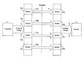
- FIG. 1is a block diagram illustrating the packets divided into 64-byte segments for transmitting over four channels are staggered in their phase relationship to one another,
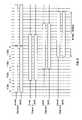
- FIG. 2is a timing chart showing a single channel bus timing of a given example
- FIG. 3illustrates the staggering performed by the transmitting device.
- Each channelincludes a plurality of core data path signals, a 32-bit wide data bus with eleven-bits of out-of-band control, and a number of non-core data path signals, which may be used to transfer additional information.
- Packetsare broken apart into segments, 64-bytes of data, and transmitted 32-bits per cycle over 16 clock cycles. Packets that are greater than 64 bytes are required to be transmitted over more than one channel.
- SOSStart of Segment
- a Start of Packet (SOP) signalis raised for one clock cycle concurrent with the first word of the packet.
- EOPEnd of a Packet
- the Empty (MPTY) signalsindicate how many bytes of the current word are valid. Since the bus is a word-wide (i.e. 32-bits will be transferred each clock cycle) up to three bytes of PAD may be present on a transfer. The MPTY signals are only valid when an EOP occurs. If the packet happens contain an error, then the Error (ERR) signal becomes active while EOP is active.
- the Valid (VAL) signalis active.
- the parity across this interfaceshould always be valid for both the data path (DPRTY) signal and the control path (CPRTY) signal.
- FIG. 3illustrates the staggering performed by the transmitting device T.
- the inventionis directed to the method and apparatus of partitioning packets into segments of predetermined size (for example, 64-bytes), serializing the segments, and transmitting them over a plurality of channels (for example, four) that have a staggered phase relationship to one another, and wherein the phase difference between adjacent channels (actually, adjacent segments in a sequence of segments that form the packet) and more than the maximum latency that can occur in any one channel, thereby maintaining the order of the serialized packet segments.
- the inventionis not limited to variable-length packets as the invention can be used for both fixed-length cells and variable-length packets.
- This inventionaddresses an obstacle and solves the problem that will be encountered by any efforts to pass variable-length packet data between separate cards.
Landscapes
- Engineering & Computer Science (AREA)
- Computer Networks & Wireless Communication (AREA)
- Signal Processing (AREA)
- Power Engineering (AREA)
- Communication Control (AREA)
- Data Exchanges In Wide-Area Networks (AREA)
- Information Transfer Systems (AREA)
Abstract
Description
- 1. The limited number of pins available across the midplane/backplane. There is currently no offering of serializer/deserializer (SERDES) devices capable of handling this bus width. Separate SERDES devices would make it difficult to receive the packet data in the proper order and with minimal signal skew.
- 2. A sixteen-byte wide bus implies that a single packet could contain up to fifteen empty bytes transferred during the end of packet. This transmission model would be very inefficient and would require a large increase in the operating frequency of the physical bus to maintain a 10 Gbps rate.
- 1. Data packets are divided into 64-byte segments,
- 2. This interface has parity protection for all data and control signals (DPRTY and CPRTY),
- 3. Each segment is serialized to four bytes wide [Data(31:0)] and each segment is tagged with a set of out-of-band control signals, as shown in
FIG. 2 . The associated control signals consist of start and end of packet indications (SOP and EOP), error indication (ERR), and the number of empty bytes transmitted during the end of packet condition. This information is then used by the receiver to properly assemble the packet.
- 1. variable length packets can be transmitted very efficiently at a low bus frequency while maintaining a bandwidth of 10 Gbps. Furthermore, in the present implementation, the segmentation of packets into 64-byte segments means that ATM cells can also be transmitted very efficiently over the bus.
- 2. The described bus topology is easily amenable to quad OC48.
- 3. Since the bus is divided into segments transmitted four-bytes at a time, there is only a need for a maximum of three empty bytes per packet. This scheme makes the bus more efficient and allows it to operate at a slower frequency while still achieving 10 Gbps rates.
Claims (8)
Priority Applications (3)
| Application Number | Priority Date | Filing Date | Title |
|---|---|---|---|
| US10/304,797US7327725B2 (en) | 2002-11-27 | 2002-11-27 | Method and apparatus capable of transferring very high data rates across a midplane or backplane |
| DE60318542TDE60318542T2 (en) | 2002-11-27 | 2003-11-24 | Method and apparatus for transmitting very high data rates over an intermediate or backplane |
| EP03300227AEP1424871B1 (en) | 2002-11-27 | 2003-11-24 | Method and apparatus capable of transferring very high data rates across a midplane or backplane |
Applications Claiming Priority (1)
| Application Number | Priority Date | Filing Date | Title |
|---|---|---|---|
| US10/304,797US7327725B2 (en) | 2002-11-27 | 2002-11-27 | Method and apparatus capable of transferring very high data rates across a midplane or backplane |
Publications (2)
| Publication Number | Publication Date |
|---|---|
| US20040100946A1 US20040100946A1 (en) | 2004-05-27 |
| US7327725B2true US7327725B2 (en) | 2008-02-05 |
Family
ID=32298043
Family Applications (1)
| Application Number | Title | Priority Date | Filing Date |
|---|---|---|---|
| US10/304,797Expired - Fee RelatedUS7327725B2 (en) | 2002-11-27 | 2002-11-27 | Method and apparatus capable of transferring very high data rates across a midplane or backplane |
Country Status (3)
| Country | Link |
|---|---|
| US (1) | US7327725B2 (en) |
| EP (1) | EP1424871B1 (en) |
| DE (1) | DE60318542T2 (en) |
Cited By (5)
| Publication number | Priority date | Publication date | Assignee | Title |
|---|---|---|---|---|
| US20080186961A1 (en)* | 2001-12-20 | 2008-08-07 | Kenneth Yi Yun | System and Method for Reevaluating Granted Arbitrated Bids |
| US20080256455A1 (en)* | 2001-12-14 | 2008-10-16 | Alberto Alessandro Della Ripa | Method for Defining the Physical Configuration of a Communication System |
| US7930604B1 (en) | 2003-02-27 | 2011-04-19 | Marvell International Ltd. | Apparatus and method for testing and debugging an integrated circuit |
| US8074135B1 (en) | 2003-02-27 | 2011-12-06 | Marvell International Ltd. | Apparatus and method for testing and debugging an integrated circuit |
| US8418129B1 (en) | 2001-12-14 | 2013-04-09 | Qualcomm Incorporated | Method for automatically generating code to define a system of hardware elements |
Families Citing this family (2)
| Publication number | Priority date | Publication date | Assignee | Title |
|---|---|---|---|---|
| US7444571B1 (en) | 2003-02-27 | 2008-10-28 | Marvell International Ltd. | Apparatus and method for testing and debugging an integrated circuit |
| US20050259692A1 (en)* | 2004-05-19 | 2005-11-24 | Zerbe Jared L | Crosstalk minimization in serial link systems |
Citations (10)
| Publication number | Priority date | Publication date | Assignee | Title |
|---|---|---|---|---|
| WO1996017489A1 (en) | 1994-11-29 | 1996-06-06 | Northern Telecom Limited | Atm inverse multiplexing |
| EP1024632A2 (en) | 1999-01-27 | 2000-08-02 | CSELT Centro Studi e Laboratori Telecomunicazioni S.p.A. | A method of and a device for digital signal transmission using inverse multiplexing |
| WO2001020947A1 (en) | 1999-09-16 | 2001-03-22 | Siemens Aktiengesellschaft | Method for minimising atm cell memories |
| US6317433B1 (en)* | 1997-10-16 | 2001-11-13 | Cisco Technology, Inc. | Method and system for optimizing transmission link bandwidth occupation in high speed digital networks |
| EP1315397A2 (en) | 2001-11-21 | 2003-05-28 | Alcatel Canada Inc. | High speed sequenced multi-channel bus |
| US6934301B2 (en)* | 2001-07-19 | 2005-08-23 | Eci Telecom Ltd. | Method and apparatus for converting data packets between a higher bandwidth network and a lower bandwidth network |
| US7006489B2 (en)* | 2001-02-23 | 2006-02-28 | Santera Systems, Inc. | Voice packet switching system and method |
| US7079528B2 (en)* | 2001-12-13 | 2006-07-18 | International Business Machines Corporation | Data communication method |
| US7130276B2 (en)* | 2001-05-31 | 2006-10-31 | Turin Networks | Hybrid time division multiplexing and data transport |
| US7142564B1 (en)* | 2001-02-07 | 2006-11-28 | Cortina Systems, Inc. | Multi-service segmentation and reassembly device with a single data path that handles both cell and packet traffic |
- 2002
- 2002-11-27USUS10/304,797patent/US7327725B2/ennot_activeExpired - Fee Related
- 2003
- 2003-11-24EPEP03300227Apatent/EP1424871B1/ennot_activeExpired - Lifetime
- 2003-11-24DEDE60318542Tpatent/DE60318542T2/ennot_activeExpired - Lifetime
Patent Citations (10)
| Publication number | Priority date | Publication date | Assignee | Title |
|---|---|---|---|---|
| WO1996017489A1 (en) | 1994-11-29 | 1996-06-06 | Northern Telecom Limited | Atm inverse multiplexing |
| US6317433B1 (en)* | 1997-10-16 | 2001-11-13 | Cisco Technology, Inc. | Method and system for optimizing transmission link bandwidth occupation in high speed digital networks |
| EP1024632A2 (en) | 1999-01-27 | 2000-08-02 | CSELT Centro Studi e Laboratori Telecomunicazioni S.p.A. | A method of and a device for digital signal transmission using inverse multiplexing |
| WO2001020947A1 (en) | 1999-09-16 | 2001-03-22 | Siemens Aktiengesellschaft | Method for minimising atm cell memories |
| US7142564B1 (en)* | 2001-02-07 | 2006-11-28 | Cortina Systems, Inc. | Multi-service segmentation and reassembly device with a single data path that handles both cell and packet traffic |
| US7006489B2 (en)* | 2001-02-23 | 2006-02-28 | Santera Systems, Inc. | Voice packet switching system and method |
| US7130276B2 (en)* | 2001-05-31 | 2006-10-31 | Turin Networks | Hybrid time division multiplexing and data transport |
| US6934301B2 (en)* | 2001-07-19 | 2005-08-23 | Eci Telecom Ltd. | Method and apparatus for converting data packets between a higher bandwidth network and a lower bandwidth network |
| EP1315397A2 (en) | 2001-11-21 | 2003-05-28 | Alcatel Canada Inc. | High speed sequenced multi-channel bus |
| US7079528B2 (en)* | 2001-12-13 | 2006-07-18 | International Business Machines Corporation | Data communication method |
Cited By (15)
| Publication number | Priority date | Publication date | Assignee | Title |
|---|---|---|---|---|
| US7965624B2 (en) | 2001-12-14 | 2011-06-21 | Qualcomm Incorporated | Data link fault tolerance |
| US20080256455A1 (en)* | 2001-12-14 | 2008-10-16 | Alberto Alessandro Della Ripa | Method for Defining the Physical Configuration of a Communication System |
| US20080253294A1 (en)* | 2001-12-14 | 2008-10-16 | Alberto Alessandro Della Ripa | Data link fault tolerance |
| US8418129B1 (en) | 2001-12-14 | 2013-04-09 | Qualcomm Incorporated | Method for automatically generating code to define a system of hardware elements |
| US7889729B2 (en) | 2001-12-20 | 2011-02-15 | Qualcomm Incorporated | System and method for reevaluating granted arbitrated bids |
| US20080186961A1 (en)* | 2001-12-20 | 2008-08-07 | Kenneth Yi Yun | System and Method for Reevaluating Granted Arbitrated Bids |
| US7930604B1 (en) | 2003-02-27 | 2011-04-19 | Marvell International Ltd. | Apparatus and method for testing and debugging an integrated circuit |
| US8074135B1 (en) | 2003-02-27 | 2011-12-06 | Marvell International Ltd. | Apparatus and method for testing and debugging an integrated circuit |
| US8161336B1 (en) | 2003-02-27 | 2012-04-17 | Marvell International Ltd. | Apparatus and method for testing and debugging an integrated circuit |
| US8356223B1 (en) | 2003-02-27 | 2013-01-15 | Marvell International Ltd. | Apparatus and method for testing and debugging an integrated circuit |
| US8572448B1 (en) | 2003-02-27 | 2013-10-29 | Marvell International Ltd. | Apparatus and method for testing and debugging an integrated circuit |
| US8713391B1 (en) | 2003-02-27 | 2014-04-29 | Marvell International Ltd. | System and method for testing an integrated circuit embedded in a system on a chip |
| US8977921B1 (en) | 2003-02-27 | 2015-03-10 | Marvell International Ltd. | System and method for providing a test result from an integrated to an analyzer |
| US9285421B1 (en) | 2003-02-27 | 2016-03-15 | Marvell International Ltd. | Serializer/deserializer and method for transferring data between an integrated circuit and a test interface |
| US9739834B1 (en) | 2003-02-27 | 2017-08-22 | Marvell International Ltd. | System and method for transferring serialized test result data from a system on a chip |
Also Published As
| Publication number | Publication date |
|---|---|
| EP1424871A3 (en) | 2006-06-14 |
| DE60318542D1 (en) | 2008-02-21 |
| EP1424871B1 (en) | 2008-01-09 |
| DE60318542T2 (en) | 2009-01-22 |
| US20040100946A1 (en) | 2004-05-27 |
| EP1424871A2 (en) | 2004-06-02 |
Similar Documents
| Publication | Publication Date | Title |
|---|---|---|
| EP1632103B1 (en) | System packet interface | |
| US5590122A (en) | Method and apparatus for reordering frames | |
| US5784370A (en) | Method and apparatus for regenerating a control signal at an asynchronous transfer mode (ATM) layer or a physical (PHY) layer | |
| US8385374B1 (en) | Multilane communication device | |
| EP1670199B1 (en) | Design of channel alignment, error handling, and clock routing using hard-wired blocks for data transmission within programmable logic integrated circuits | |
| KR950005147B1 (en) | Reliable synchronous inter-node communication in a self-routing network | |
| US6385208B1 (en) | Serial media independent interface | |
| US6996738B2 (en) | Robust and scalable de-skew method for data path skew control | |
| US6738935B1 (en) | Coding sublayer for multi-channel media with error correction | |
| US20020126704A1 (en) | System interface for cell and/or packet transfer at aggregate data rates of up to 10 Gb/s | |
| CN110620809B (en) | System and method for performing inter-packet gap repair for lossy protocols | |
| US20030112798A1 (en) | Data communication method | |
| US7327725B2 (en) | Method and apparatus capable of transferring very high data rates across a midplane or backplane | |
| US6882661B1 (en) | System for detection of asynchronous packet rates and maintenance of maximum theoretical packet rate | |
| US7480282B2 (en) | Methods and apparatus for controlling ethernet packet transfers between clock domains | |
| US7535844B1 (en) | Method and apparatus for digital signal communication | |
| WO2023104210A1 (en) | Data transmission chip and electronic device | |
| EP0310360B1 (en) | Data communication method and apparatus | |
| US6826187B1 (en) | Interfacing between a physical layer and a bus | |
| US9160604B2 (en) | Systems and methods to explicitly realign packets | |
| US11714777B2 (en) | Method for performing data transmission control of inter field programmable gate arrays and associated apparatus | |
| US6429794B1 (en) | Format converter | |
| US5138641A (en) | Bit residue correction in a dlc receiver | |
| TWI893177B (en) | Method for data processing of frame receiving of an interconnection protocol and storage device | |
| KR20250040171A (en) | Apparatus and Method for Transmitting Packet in Physical Layer |
Legal Events
| Date | Code | Title | Description |
|---|---|---|---|
| AS | Assignment | Owner name:ALCATEL CANADA INC., CANADA Free format text:ASSIGNMENT OF ASSIGNORS INTEREST;ASSIGNORS:SCHRIEL, JAMES MICHEAL;MEGARITY, MARK R.;REEL/FRAME:013550/0428 Effective date:20021126 | |
| FEPP | Fee payment procedure | Free format text:PAYOR NUMBER ASSIGNED (ORIGINAL EVENT CODE: ASPN); ENTITY STATUS OF PATENT OWNER: LARGE ENTITY | |
| STCF | Information on status: patent grant | Free format text:PATENTED CASE | |
| FPAY | Fee payment | Year of fee payment:4 | |
| AS | Assignment | Owner name:CREDIT SUISSE AG, NEW YORK Free format text:SECURITY INTEREST;ASSIGNOR:ALCATEL-LUCENT CANADA INC.;REEL/FRAME:029826/0927 Effective date:20130130 | |
| AS | Assignment | Owner name:ALCATEL-LUCENT CANADA INC., CANADA Free format text:RELEASE OF SECURITY INTEREST;ASSIGNOR:CREDIT SUISSE AG;REEL/FRAME:033686/0798 Effective date:20140819 | |
| FPAY | Fee payment | Year of fee payment:8 | |
| AS | Assignment | Owner name:ALCATEL-LLUCENT CANADA INC., CANADA Free format text:MERGER;ASSIGNOR:ALCATEL CANADA INC.;REEL/FRAME:047714/0041 Effective date:20070101 | |
| AS | Assignment | Owner name:PIECE FUTURE PTE LTD, SINGAPORE Free format text:CHANGE OF NAME;ASSIGNOR:NOKIA CANADA INC.;REEL/FRAME:048376/0549 Effective date:20181124 | |
| FEPP | Fee payment procedure | Free format text:MAINTENANCE FEE REMINDER MAILED (ORIGINAL EVENT CODE: REM.); ENTITY STATUS OF PATENT OWNER: LARGE ENTITY | |
| LAPS | Lapse for failure to pay maintenance fees | Free format text:PATENT EXPIRED FOR FAILURE TO PAY MAINTENANCE FEES (ORIGINAL EVENT CODE: EXP.); ENTITY STATUS OF PATENT OWNER: LARGE ENTITY | |
| STCH | Information on status: patent discontinuation | Free format text:PATENT EXPIRED DUE TO NONPAYMENT OF MAINTENANCE FEES UNDER 37 CFR 1.362 | |
| FP | Lapsed due to failure to pay maintenance fee | Effective date:20200205 |