US7327553B2 - Feedthrough capacitor filter assemblies with laminar flow delaminations for helium leak detection - Google Patents
Feedthrough capacitor filter assemblies with laminar flow delaminations for helium leak detectionDownload PDFInfo
- Publication number
- US7327553B2 US7327553B2US11/161,198US16119805AUS7327553B2US 7327553 B2US7327553 B2US 7327553B2US 16119805 AUS16119805 AUS 16119805AUS 7327553 B2US7327553 B2US 7327553B2
- Authority
- US
- United States
- Prior art keywords
- capacitor
- insulator
- washer
- filter assembly
- electrode plates
- Prior art date
- Legal status (The legal status is an assumption and is not a legal conclusion. Google has not performed a legal analysis and makes no representation as to the accuracy of the status listed.)
- Expired - Fee Related, expires
Links
- 239000003990capacitorSubstances0.000titleclaimsabstractdescription84
- 230000032798delaminationEffects0.000titleclaimsabstractdescription28
- SWQJXJOGLNCZEY-UHFFFAOYSA-Nhelium atomChemical compound[He]SWQJXJOGLNCZEY-UHFFFAOYSA-N0.000titleabstractdescription30
- 229910052734heliumInorganic materials0.000titleabstractdescription27
- 239000001307heliumSubstances0.000titleabstractdescription21
- 238000001514detection methodMethods0.000titleabstractdescription19
- 230000000712assemblyEffects0.000titledescription6
- 238000000429assemblyMethods0.000titledescription6
- 239000012212insulatorSubstances0.000claimsdescription62
- 239000000463materialSubstances0.000claimsdescription28
- 239000000853adhesiveSubstances0.000claimsdescription22
- 230000001070adhesive effectEffects0.000claimsdescription22
- 239000012790adhesive layerSubstances0.000claimsdescription19
- PNEYBMLMFCGWSK-UHFFFAOYSA-Naluminium oxideInorganic materials[O-2].[O-2].[O-2].[Al+3].[Al+3]PNEYBMLMFCGWSK-UHFFFAOYSA-N0.000claimsdescription16
- 230000000747cardiac effectEffects0.000claimsdescription13
- 239000007943implantSubstances0.000claimsdescription13
- 239000004642PolyimideSubstances0.000claimsdescription11
- 229920001721polyimidePolymers0.000claimsdescription11
- NOESYZHRGYRDHS-UHFFFAOYSA-NinsulinChemical compoundN1C(=O)C(NC(=O)C(CCC(N)=O)NC(=O)C(CCC(O)=O)NC(=O)C(C(C)C)NC(=O)C(NC(=O)CN)C(C)CC)CSSCC(C(NC(CO)C(=O)NC(CC(C)C)C(=O)NC(CC=2C=CC(O)=CC=2)C(=O)NC(CCC(N)=O)C(=O)NC(CC(C)C)C(=O)NC(CCC(O)=O)C(=O)NC(CC(N)=O)C(=O)NC(CC=2C=CC(O)=CC=2)C(=O)NC(CSSCC(NC(=O)C(C(C)C)NC(=O)C(CC(C)C)NC(=O)C(CC=2C=CC(O)=CC=2)NC(=O)C(CC(C)C)NC(=O)C(C)NC(=O)C(CCC(O)=O)NC(=O)C(C(C)C)NC(=O)C(CC(C)C)NC(=O)C(CC=2NC=NC=2)NC(=O)C(CO)NC(=O)CNC2=O)C(=O)NCC(=O)NC(CCC(O)=O)C(=O)NC(CCCNC(N)=N)C(=O)NCC(=O)NC(CC=3C=CC=CC=3)C(=O)NC(CC=3C=CC=CC=3)C(=O)NC(CC=3C=CC(O)=CC=3)C(=O)NC(C(C)O)C(=O)N3C(CCC3)C(=O)NC(CCCCN)C(=O)NC(C)C(O)=O)C(=O)NC(CC(N)=O)C(O)=O)=O)NC(=O)C(C(C)CC)NC(=O)C(CO)NC(=O)C(C(C)O)NC(=O)C1CSSCC2NC(=O)C(CC(C)C)NC(=O)C(NC(=O)C(CCC(N)=O)NC(=O)C(CC(N)=O)NC(=O)C(NC(=O)C(N)CC=1C=CC=CC=1)C(C)C)CC1=CN=CN1NOESYZHRGYRDHS-UHFFFAOYSA-N0.000claimsdescription10
- 239000007788liquidSubstances0.000claimsdescription7
- 229920000642polymerPolymers0.000claimsdescription6
- 206010007559Cardiac failure congestiveDiseases0.000claimsdescription5
- 206010019280Heart failuresDiseases0.000claimsdescription5
- 206010021639IncontinenceDiseases0.000claimsdescription5
- 102000004877InsulinHuman genes0.000claimsdescription5
- 108090001061InsulinProteins0.000claimsdescription5
- 230000008468bone growthEffects0.000claimsdescription5
- 210000004556brainAnatomy0.000claimsdescription5
- 239000003814drugSubstances0.000claimsdescription5
- 229940079593drugDrugs0.000claimsdescription5
- 230000002496gastric effectEffects0.000claimsdescription5
- 239000003324growth hormone secretagogueSubstances0.000claimsdescription5
- 229940125396insulinDrugs0.000claimsdescription5
- 210000000278spinal cordAnatomy0.000claimsdescription5
- 230000002861ventricularEffects0.000claimsdescription5
- 239000004033plasticSubstances0.000claimsdescription4
- 238000007789sealingMethods0.000claims2
- WABPQHHGFIMREM-UHFFFAOYSA-Nlead(0)Chemical compound[Pb]WABPQHHGFIMREM-UHFFFAOYSA-N0.000abstractdescription29
- 238000012360testing methodMethods0.000abstractdescription14
- PCHJSUWPFVWCPO-UHFFFAOYSA-NgoldChemical compound[Au]PCHJSUWPFVWCPO-UHFFFAOYSA-N0.000abstractdescription12
- 239000010931goldSubstances0.000abstractdescription12
- 229910052737goldInorganic materials0.000abstractdescription12
- 239000003566sealing materialSubstances0.000abstract1
- XLYOFNOQVPJJNP-UHFFFAOYSA-NwaterSubstancesOXLYOFNOQVPJJNP-UHFFFAOYSA-N0.000description17
- UIIMBOGNXHQVGW-UHFFFAOYSA-MSodium bicarbonateChemical compound[Na+].OC([O-])=OUIIMBOGNXHQVGW-UHFFFAOYSA-M0.000description15
- 239000003985ceramic capacitorSubstances0.000description11
- 230000002950deficientEffects0.000description9
- 229910000030sodium bicarbonateInorganic materials0.000description7
- 235000017557sodium bicarbonateNutrition0.000description7
- 210000001124body fluidAnatomy0.000description5
- 239000010839body fluidSubstances0.000description5
- 230000015556catabolic processEffects0.000description5
- 239000011521glassSubstances0.000description5
- 238000000034methodMethods0.000description5
- 230000005684electric fieldEffects0.000description4
- 239000007789gasSubstances0.000description4
- 238000004519manufacturing processMethods0.000description4
- BASFCYQUMIYNBI-UHFFFAOYSA-NplatinumChemical compound[Pt]BASFCYQUMIYNBI-UHFFFAOYSA-N0.000description4
- IJGRMHOSHXDMSA-UHFFFAOYSA-NAtomic nitrogenChemical compoundN#NIJGRMHOSHXDMSA-UHFFFAOYSA-N0.000description3
- 239000004593EpoxySubstances0.000description3
- 238000005422blastingMethods0.000description3
- 238000004140cleaningMethods0.000description3
- 238000010276constructionMethods0.000description3
- 239000000356contaminantSubstances0.000description3
- 239000012530fluidSubstances0.000description3
- 239000001257hydrogenSubstances0.000description3
- 229910052739hydrogenInorganic materials0.000description3
- 125000004433nitrogen atomChemical groupN*0.000description3
- 230000002093peripheral effectEffects0.000description3
- 238000000926separation methodMethods0.000description3
- UIIMBOGNXHQVGW-DEQYMQKBSA-MSodium bicarbonate-14CChemical compound[Na+].O[14C]([O-])=OUIIMBOGNXHQVGW-DEQYMQKBSA-M0.000description2
- 125000004429atomChemical group0.000description2
- QVGXLLKOCUKJST-UHFFFAOYSA-Natomic oxygenChemical compound[O]QVGXLLKOCUKJST-UHFFFAOYSA-N0.000description2
- 230000008901benefitEffects0.000description2
- 239000000919ceramicSubstances0.000description2
- 229920001940conductive polymerPolymers0.000description2
- 230000007797corrosionEffects0.000description2
- 238000005260corrosionMethods0.000description2
- 238000001035dryingMethods0.000description2
- 230000009977dual effectEffects0.000description2
- 125000004435hydrogen atomChemical group[H]*0.000description2
- 238000009413insulationMethods0.000description2
- 230000007257malfunctionEffects0.000description2
- 229910052751metalInorganic materials0.000description2
- 239000002184metalSubstances0.000description2
- 238000001465metallisationMethods0.000description2
- 239000001301oxygenSubstances0.000description2
- 229910052760oxygenInorganic materials0.000description2
- 229910052697platinumInorganic materials0.000description2
- HWLDNSXPUQTBOD-UHFFFAOYSA-Nplatinum-iridium alloyChemical compound[Ir].[Pt]HWLDNSXPUQTBOD-UHFFFAOYSA-N0.000description2
- 239000002904solventSubstances0.000description2
- 235000013619trace mineralNutrition0.000description2
- 239000011573trace mineralSubstances0.000description2
- MYMOFIZGZYHOMD-UHFFFAOYSA-NDioxygenChemical compoundO=OMYMOFIZGZYHOMD-UHFFFAOYSA-N0.000description1
- 206010015856ExtrasystolesDiseases0.000description1
- 208000013201Stress fractureDiseases0.000description1
- RTAQQCXQSZGOHL-UHFFFAOYSA-NTitaniumChemical compound[Ti]RTAQQCXQSZGOHL-UHFFFAOYSA-N0.000description1
- 239000000560biocompatible materialSubstances0.000description1
- 230000005540biological transmissionEffects0.000description1
- 238000005219brazingMethods0.000description1
- 230000001413cellular effectEffects0.000description1
- 229910010293ceramic materialInorganic materials0.000description1
- 239000011248coating agentSubstances0.000description1
- 238000000576coating methodMethods0.000description1
- 230000006835compressionEffects0.000description1
- 238000007906compressionMethods0.000description1
- 238000011109contaminationMethods0.000description1
- 238000005520cutting processMethods0.000description1
- 239000008367deionised waterSubstances0.000description1
- 230000001419dependent effectEffects0.000description1
- 238000009826distributionMethods0.000description1
- 238000010292electrical insulationMethods0.000description1
- 238000002265electronic spectrumMethods0.000description1
- 238000005516engineering processMethods0.000description1
- 230000006870functionEffects0.000description1
- -1i.e.Substances0.000description1
- 238000002513implantationMethods0.000description1
- 239000011810insulating materialSubstances0.000description1
- 238000003698laser cuttingMethods0.000description1
- 238000005259measurementMethods0.000description1
- 238000012986modificationMethods0.000description1
- 230000004048modificationEffects0.000description1
- 229910052754neonInorganic materials0.000description1
- GKAOGPIIYCISHV-UHFFFAOYSA-Nneon atomChemical compound[Ne]GKAOGPIIYCISHV-UHFFFAOYSA-N0.000description1
- 229910052758niobiumInorganic materials0.000description1
- 239000010955niobiumSubstances0.000description1
- GUCVJGMIXFAOAE-UHFFFAOYSA-Nniobium atomChemical compound[Nb]GUCVJGMIXFAOAE-UHFFFAOYSA-N0.000description1
- 229910052757nitrogenInorganic materials0.000description1
- 230000037361pathwayEffects0.000description1
- 230000035515penetrationEffects0.000description1
- 230000035699permeabilityEffects0.000description1
- 230000008569processEffects0.000description1
- 230000035755proliferationEffects0.000description1
- 230000035939shockEffects0.000description1
- 229910000679solderInorganic materials0.000description1
- 229910052715tantalumInorganic materials0.000description1
- GUVRBAGPIYLISA-UHFFFAOYSA-Ntantalum atomChemical compound[Ta]GUVRBAGPIYLISA-UHFFFAOYSA-N0.000description1
- 229920001169thermoplasticPolymers0.000description1
- 239000004416thermosoftening plasticSubstances0.000description1
- 239000010936titaniumSubstances0.000description1
- 229910052719titaniumInorganic materials0.000description1
Images


Classifications
- H—ELECTRICITY
- H01—ELECTRIC ELEMENTS
- H01G—CAPACITORS; CAPACITORS, RECTIFIERS, DETECTORS, SWITCHING DEVICES, LIGHT-SENSITIVE OR TEMPERATURE-SENSITIVE DEVICES OF THE ELECTROLYTIC TYPE
- H01G4/00—Fixed capacitors; Processes of their manufacture
- H01G4/35—Feed-through capacitors or anti-noise capacitors
- A—HUMAN NECESSITIES
- A61—MEDICAL OR VETERINARY SCIENCE; HYGIENE
- A61N—ELECTROTHERAPY; MAGNETOTHERAPY; RADIATION THERAPY; ULTRASOUND THERAPY
- A61N1/00—Electrotherapy; Circuits therefor
- A61N1/18—Applying electric currents by contact electrodes
- A61N1/32—Applying electric currents by contact electrodes alternating or intermittent currents
- A61N1/36—Applying electric currents by contact electrodes alternating or intermittent currents for stimulation
- A61N1/372—Arrangements in connection with the implantation of stimulators
- A61N1/375—Constructional arrangements, e.g. casings
- A61N1/3752—Details of casing-lead connections
- A61N1/3754—Feedthroughs
Definitions
- This inventionrelates generally to feedthrough capacitor filter assemblies, particularly of the type used in implantable medical devices such as cardiac pacemakers, cardioverter defibrillators and the like, to decouple and shield internal electronic components of the medical device from undesirable electromagnetic interference (EMI) signals. More specifically, this invention relates to an improved feedthrough capacitor filter assembly of the type incorporating a hermetic seal to prevent passage or leakage of fluids through the filter assembly, wherein a laminar flow delamination is provided to accommodate and facilitate post manufacture and pre-usage testing of the hermetic seal.
- EMIelectromagnetic interference
- Feedthrough terminal pin assembliesare generally well known in the art for use in connecting electrical signals through the housing or case of an electronic instrument.
- the terminal pin assemblycomprises one or more conductive terminal pins supported by an insulator structure for feedthrough passage of electrical signals from the exterior to the interior of the medical device.
- an insulator structurefor feedthrough passage of electrical signals from the exterior to the interior of the medical device.
- Many different insulator structures and related mounting methodsare known for use in medical devices wherein the insulator structure provides a hermetic seal to prevent entry of patient body fluids into the medical device housing, where such body fluids could otherwise interfere with the operation of and/or cause damage to internal electronic components of the medical device.
- the hermetic sealIn the past, two primary technologies have been employed to manufacture the hermetic seal.
- One techniqueinvolves the use of an alumina insulator which is sputtered to accept brazing material. This alumina insulator is brazed to the terminal pin or pins, and also to an outer metal ferrule of titanium or the like. The alumina insulator supports the terminal pin or pins in insulated spaced relation from the ferrule which is adapted for suitable mounting within an access opening formed in the housing of the medical device.
- the hermetic sealcomprises a glass-based seal forming a compression or fused glass seal for supporting the terminal pin or pins within an outer metal ferrule.
- the feedthrough terminal pinsare typically connected to one or more lead wires which, in the example of a cardiac pacemaker, sense signals from the patient's heart and also couple electronic pacing pulses from the medical device to the patient's heart.
- lead wirescan act as an antenna to collect stray electromagnetic interference (EMI) signals for transmission via the terminal pins into the interior of the medical device.
- EMIstray electromagnetic interference
- Such unwanted EMI signalscan disrupt proper operation of the medical device, resulting in malfunction or failure.
- stray EMI signals emanating from cellular telephonescan inhibit pacemaker operation, resulting in asynchronous pacing, tracking and missed beats.
- hermetically sealed feedthrough terminal pin assemblieshave been designed to include a filter capacitor for decoupling EMI signals in a manner preventing such unwanted signals from entering the housing of the implantable medical device. See, for example, U.S. Pat. Nos. 4,424,551; 5,333,095; 5,751,539; 5,905,627; 5,973,906; 6,008,980; and 6,566,978.
- While feedthrough capacitor filter assemblieshave provided a significant advance in the art, one potential area of concern is that the filter capacitor is often incorporated into the terminal pin assembly in a way that can mask a defective hermetic seal. More particularly, a defective braze or a defective glass-based seal structure, which would permit undesirable leakage of patient body fluids when mounted on a medical device and implanted into a patient, can be obstructed by the mounting of the filter capacitor and its associated electromechanical connections.
- a ceramic filter capacitoris bonded to a glass seal and then embedded in epoxy material.
- Typical post-manufacture leak testingis performed by mounting the feedthrough assembly in a test fixture, and then subjecting one side of the feedthrough assembly to a selected pressurized gas such as helium. While the bulk permeability of the epoxy material is such that helium under pressure can penetrate therethrough in the presence of a defective hermetic seal, the duration of this pressure test (typically a few seconds) is often insufficient to permit such penetration. Accordingly, the epoxy material can mask the defective hermetic seal.
- the thus-tested feedthrough assemblycan then mistakenly be incorporated into a medical device and implanted into a patient, wherein slow leakage of patient body fluids through the feedthrough assembly can cause the medical device to malfunction or fail.
- FIGS. 1 and 2taken from FIGS. 1 and 2 of U.S. Pat. No. 6,566,978, disclose a quadpolar feedthrough capacitor 16 mounted on a quadpolar terminal 10 .
- a gap 38is formed between the ceramic capacitor 16 and the alumina hermetic seal insulator 36 .
- the purpose of this gap 38is to allow for ready passage of leak detection gases from the hermetic terminal areas or along lead wire 14 through the insulator 36 to flow to the leak detection vent hole 39 .
- Conductive polyimidesare typically used to form the electrical connection between the lead wire 14 and the inside diameter 22 of the ceramic capacitor 16 .
- Conductive polyimidesare also typically used to form the connection between the capacitor 16 outside diameter metallization 25 and the ferrule 26 .
- these conductive polyimide materialsare typically cleaned using a grit blasting system with sodium bicarbonate as the blasting medium.
- sodium bicarbonateotherwise known as baking soda, is highly soluble in water. Accordingly, de-ionized water rinses are used to ensure that no baking soda is left on the part but the sodium bicarbonate dissolves readily into the water cleaning solvent.
- trace elements of the sodium bicarbonateare then left inside any cavity or air gap, for example, the gap 38 formed between the ceramic capacitor 16 and the alumina insulator 36 described in the U.S. Pat. No. 6,566,978.
- a sodium bicarbonate residueis very hygroscopic. That is, it will tend to absorb moisture from the surrounding air which can degrade the electrical insulation properties of the feedthrough filtered capacitor assembly 10 .
- the insulation resistance requirementbe 100 Gigaohms or even higher.
- the insulation resistanceIn order to consistently achieve an insulation resistance greater than 100 Gigaohms, it is essential that all surfaces be extremely clean. Accordingly, any trace element of sodium bicarbonate or other contaminant left behind leads to rejection of the devices.
- AEDsautomatic external defibrillators
- the gap ( 38 , 138 or 238 )is an area where electric field enhancement can occur. That is, when a high voltage is applied to the lead wire 18 , there could be a tendency for a high electric field stress to occur in the air gap 38 . These high electric field stresses can lead to ionization of the air gap 38 , a resulting plasma and a catastrophic high voltage breakdown of the device 10 . This so called avalanche breakdown would cause an implantable medical device to not function, which would of course be life threatening for a pacemaker or a defibrillator dependent patient.
- FIGS. 3 and 4taken from FIGS. 5 and 6 of U.S. Pat. No. 6,765,779, disclose a unipolar feedthrough capacitor 100 mounted on a unipolar hermetic terminal 102 .
- the feedthrough capacitor 100incorporates outer diameter metallization 114 .
- An electrical attachment 132is made from the capacitor outside diameter 114 to the ferrule 118 .
- This connection 132is typically formed with a high temperature thermal setting conductive polymer such as a conductive polyimide. There are gaps left around the circumference of connection material 132 to provide for helium leak detection pathways. This is generally described in U.S. Pat. No. 6,765,779 in column 2 lines 24 through 67 and in column 3 lines 1 through 33.
- this axial gap 126is formed between the ceramic feedthrough capacitor 100 and the surface of the hermetic terminal 102 .
- the purpose of this axial gap 126is so that if there was a defective gold braze 128 , 130 , helium atoms could readily penetrate the annular space between the lead wire 116 and the inside diameter of the insulator 124 . Accordingly, said helium atoms could then pass readily through axial gap 126 and out through the spaces left in the circumferential conductive polyimide attachment material 132 .
- leaving an axial gap 126can trap contaminants between the capacitor 100 and the insulator 124 or terminal 102 and also has the tendency to enhance (squeeze or compress) electric fields during the application of a high voltage to the device.
- the present inventionfulfills this need by providing an improved feedthrough capacitor filter assembly suitable for use in an implantable medical device or the like, wherein the feedthrough assembly includes a laminar delamination gap for accommodating and facilitating post-manufactured hermetic seal testing.
- an improved electromagnetic interference (EMI) feedthrough filter assemblyfor use in an active implantable medical device (AIMD) is provided.
- the assemblycomprises a capacitor having first and second sets of electrode plates embedded within a dielectric body such as a monolithic ceramic material.
- a conductive ferruleis conductively coupled to the second set of electrode plates.
- An insulatoris adjacent to an axial side of the capacitor and extends across and seals an aperture in the ferrule.
- a conductive terminal pinextends through the capacitor and insulator in conductive relation with the first set of electrode plates.
- a washeris disposed between the insulator and the capacitor body, wherein the insulator and the washer cooperatively define a laminator delamination gap.
- the assemblymay further comprise an adhesive layer disposed between the capacitor and the washer that laminates the washer to the capacitor following a curing process.
- the adhesive layermay be formed from a liquid polymer, an adhesive washer, a thermo plastic adhesive coated material, or any similarly adhesive material.
- the washermay be formed from a non-conductive or insulative material, i.e., polyimide sheet or a thin sheet of alumina.
- the assemblymay include a plurality of terminal pins extending through the insulator and capacitor body in conductive relation with the first set of electrode plates.
- the insulatormay comprise a plurality of insulators corresponding to a plurality of ferrule apertures.
- the assemblyis designed to be used with various AIMDs, including but not limited to, cardiac pacemakers, cardiac sensing systems, neurostimulators, cochlear implants, deep brain stimulators, implantable defibrillators, congestive heart failure devices, hearing implants, drug pumps, ventricular assist devices, insulin pumps, spinal cord stimulators, artificial hearts, incontinence devices, bone growth stimulators, gastric pacemakers, or prosthetic devices.
- AIMDsincluding but not limited to, cardiac pacemakers, cardiac sensing systems, neurostimulators, cochlear implants, deep brain stimulators, implantable defibrillators, congestive heart failure devices, hearing implants, drug pumps, ventricular assist devices, insulin pumps, spinal cord stimulators, artificial hearts, incontinence devices, bone growth stimulators, gastric pacemakers, or prosthetic devices.
- FIG. 1is an isometric view of a prior art quadpolar feedthrough capacitor mounted to a quadpolar hermetic terminal;
- FIG. 2is a cross-sectional view taken along line 2 - 2 of FIG. 1 ;
- FIG. 3is an isometric view of a prior art unipolar feedthrough capacitor mounted to a unipolar hermetic terminal;
- FIG. 4is a cross-sectional view taken along line 4 - 4 of FIG. 3 ;
- FIG. 5is an isometric view of a unipolar feedthrough capacitor mounted to a unipolar hermetic terminal embodying the present invention
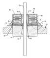
- FIG. 6is a cross-sectional view taken along line 6 - 6 of FIG. 5 ;
- FIG. 7is a fragmented exploded view taken of the area indicated by the number 7 in FIG. 6 ;
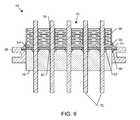
- FIG. 8is an isometric view of another embodiment of the present invention.
- FIG. 9is a cross-sectional view taken along line 9 - 9 of FIG. 8 .
- An improved feedthrough capacitor filter assemblyis provided for use in active implantable medical devices (AIMDs) and the like, such as in a cardiac pacemaker, a cardiac sensing system, a neurostimulator, a cochlear implant, a deep brain stimulator, an implantable defibrillator, a congestive heart failure device, a hearing implant, a drug pump, a ventricular assist device, an insulin pump, a spinal cord stimulator, an artificial heart, an incontinence device, a bone growth stimulator, a gastric pacemaker, or a prosthetic device.
- This improved filter assemblyincludes a laminar delamination gap for facilitated hermetic seal testing subsequent to manufacture and prior to use.
- FIGS. 1 and 2taken from FIGS. 1 and 2 of U.S. Pat. No. 6,566,978, depict a variation on a feedthrough filter assembly 10 with a leak detection vent 39 from the prior art.
- the feedthrough filter assembly 10comprises a capacitor body 16 , at least one terminal pin 14 extending through the capacitor 16 , an outer ferrule 26 mounted about the capacitor 16 , an insulator 36 seated within or over the ferrule 26 at one side of the capacitor 16 providing an hermetic seal, and a leak detection vent 38 , 39 formed in the assembly 10 .
- the leak detection vent 38 , 39is designed to accommodate and facilitate post-assembly fluid leak testing of the hermetic seal, by subjecting the hermetic seal to a selected pressurized test gas such as helium or the like, prior to implantation of the assembly 10 in a medical device into a patient.
- a selected pressurized test gassuch as helium or the like
- the insulator 36 and capacitor 16are separated by a short axial gap 38 created by the presence of a dissolvable washer. This gap provides access to a leak detection vent or passage 39 , which facilitates detecting the presence of the test gas leaking past the hermetic seal.
- FIGS. 3 and 4taken from FIGS. 5 and 6 of U.S. Pat. No. 6,765,779, depict other prior art embodiments of capacitors 100 mounted on terminals 102 employing alternate configurations for leak detection.
- the terminal 102comprises a capacitor 100 , a ferrule 118 having a central aperture, an insulator 124 within the central aperture to prevent passage of fluid such as patient body fluids, and a terminal pin 116 .
- the insulator 124 and the capacitor 100cooperate to define a short axial gap 126 therebetween. This gap 126 forms a leak detection vent and facilitates leak detection.
- the capacitor 100is mechanically and conductively attached to the ferrule 118 by means of peripheral support material 132 while maintaining the axial gap 126 between the capacitor 100 and the insulator 124 .
- the axial gap 126is small to preclude leakage of EMI.
- the peripheral support material 132is preferably to allow for passage of helium during hermetic seal testing of the complete assembly. As shown in FIG. 2 , there are substantial gaps between instances of the peripheral support material 132 , which allows for the passage of helium during a leak detection test.
- FIGS. 5 and 6illustrate a unipolar device 50 similar to that previously described in U.S. Pat. No. 6,765,779.
- the alumina ceramic insulator 52has been modified so that it is flush with the ferrule 56 and does not extend upward, above the top surface of the ferrule 56 .
- a non-conductive and non-adhesive washer 54has been added and is pressed firmly against the top surface of the alumina insulator 52 . (This could also be pressed against the top surface of the ferrule 56 .)
- This non-adhesive washer 54is typically formed from a high temperature material such as a non-conductive polyimide sheet.
- the washer 54 materialcan be shaped by die cutting, laser cutting or the like.
- the non-adhesive washer 54can also be formed of a thin sheet of alumina or other suitable insulating material. The important feature is that the non-adhesive washer 54 be flat and have the ability to be pressed firmly down against the alumina or equivalent insulator 54 .
- One or more adhesive layers 58i.e., liquid polymer washers, are then placed on top of the washer 54 .
- the most suitable material for thisis a thermal plastic adhesive coated tape material.
- Conformal coating 80is optional and can be deposited on the top surface of the capacitor to improve its high voltage standoff capability and/or its moisture resistance.
- the entire assemblyis pre-weighted and then cured at an elevated temperature. Since both the top and bottom surfaces of the adhesive layer 58 are coated with an adhesive, they laminate both to the bottom of the ceramic capacitor 60 and to the top of the non-adhesive washer 54 . It is an important feature of the present invention that the bottom surface of the non-adhesive washer 54 not be laminated to the top surface of the insulator 52 or the ferrule 56 of the terminal 50 . This leaves a very thin laminar delamination gap 62 which is best seen in the exploded view of FIG. 7 . Even in FIG. 7 , delamination gap 62 is exaggerated in thickness for purposes of depiction.
- delamination gap 62is a very thin gap on the order of 50 angstroms or so. However, this small delamination gap 62 is sufficient to readily allow helium atoms to pass during a helium leak detection test. For example, if either or both braze joint 64 or 66 were defective, this would allow helium to penetrate through the defective braze 64 or 66 or a corresponding crack in the alumina insulator 52 into the laminar delamination gap 62 and out to the other side of ferrule 56 where it could be readily detected by the helium leak detector.
- the atomic radius of a helium atomis 0.49 angstroms.
- the diametertherefore is 0.98 angstroms.
- the diameter of a nitrogen atomis 1.5 angstroms.
- a nitrogen moleculeis composed of two nitrogen atoms bonded to each other. The molecule has an elliptical shape. However, helium atoms do not bond to each other. Thus, the “molecule” is represented by a single helium atom.
- N 2nitrogen
- He 2diatomic
- Quantum mechanical calculations of the orbital radius of He and N atomsare 291 and 521 nanometers respectively.
- Commonly used molecular models for waterutilize O—H lengths between 0.957 angstrom and 1.00 angstrom and H—O—H angles of 104.52 degrees to 109.5 degrees.
- the van der Waals diameter of waterhas been reported as identical with that of isoelectronic neon (2.82 angstroms).
- a significant advantage of thisis that the large gap as previously described above in the prior art and shown in FIGS. 1 through 4 has been eliminated.
- waterhas been generally precluded from entering the space between the non-adhesive washer 54 and the insulator 52 ; however, helium is free to flow. This is also very important during water cleaning after sodium bicarbonate blasting. Accordingly, since water molecules do not readily penetrate the laminar delamination gap 62 , this also means that the ionically dissolved sodium bicarbonate, which is contained in the water, will not deposit in this surface area.
- connection 70 between the capacitor 60 outside diameter termination 68 and the ferrule 56is shown.
- Connection 70is typically a conductive thermal setting polyimide or the like. As described in U.S. Pat. No.
- this electrical connection material 70be discontinuous around the outside diameter of ceramic capacitor 60 . This demonstrates the fact that any helium that is contained within the laminar delamination gap 62 can pass readily to the outside of the ceramic capacitor 60 .
- lead wires 72that tend to have non-conductive surfaces due to corrosion or oxides, described in U.S. Pat. No. 6,566,978 and incorporated by reference herein in its entirety. This includes the family of niobium and tantalum. It is desirable to have the inside diameter electrical connection 74 make direct contact to gold braze joint 64 . In this regard, it is necessary to form a low impedance electrical connection between the capacitor inside diameter termination 76 directly to lead wire 72 . In this case, the electrical connection 74 is from the inside diameter termination 76 through the conductive thermal setting polymer 74 directly to gold braze joint 64 and then in turn to lead wire 72 .
- gold braze joint 64is formed at an elevated temperature sufficient to burn through any surface contamination, oxide or corrosion product on the surface of lead wire 72 . Accordingly, the connection between the gold braze joint 64 and the lead wire 72 is metallurgic and very low impedance. However, in accordance with an embodiment of the present invention, the inside diameter termination 76 of the feedthrough capacitor 60 has been sealed off from the gold braze joint 64 by means of washer 54 and adhesive layer 58 as shown. That is, electrical connection 74 is not free to penetrate down and touch off against the gold braze joint 64 .
- FIGS. 8 and 9illustrate an alternate embodiment of the present invention in view of the above.
- the lead wires 72are of platinum or of platinum iridium construction, which is a suitable biocompatible material. Platinum or platinum iridium does not form heavy oxides. Accordingly, one can make a low impedance electrical connection directly from the capacitor inside diameter termination 76 to the lead wire 72 itself. This eliminates the need for the application of the material 78 as previously described in FIG. 6 .
- non-adhesive washer 54has been placed against the top surface of the alumina insulator 52 .
- an adhesive layer 58i.e., liquid thermal setting conductive polymer washer, is placed such that it will bond to the top surface of the non-adhesive washer 54 .
- the ceramic capacitor 60is then placed in sandwich construction over the other surface of the adhesive layer 58 .
- the adhesive layer 58can be formed as a single unit or several adhesively coated units stacked together.
- the assemblyis then compressed with a weighting fixture and cured at elevated temperature.
- a very small spaceis formed as a laminar delamination gap between the two surfaces.
- This laminar delamination gap 62occurs since there are no adhesive materials in this space. As previously discussed in accordance with an embodiment of the present invention, this laminar delamination gap 62 is sufficient to allow for ready passage of helium molecules during a helium leak test. Accordingly, if there was a micro fracture within the hermetic insulator 52 or a defective gold braze joint 64 or 66 , then helium molecules could readily pass through the laminar delamination gap 62 of the present invention and then flow out to be detected by the helium leak detection equipment. As previously described, the electrical connection material 70 that connects the capacitor outside diameter 68 to the gold braze 66 of ferrule 56 is discontinuous. That is, it does not go around the entire perimeter or outside diameter of the feedthrough capacitor 60 . These gaps are important so that helium flowing through the laminar delamination gap 62 is not blocked by the connection material 70 and can flow readily outside of the ceramic capacitor 60 .
- FIG. 8there are a number of possible alternatives available.
- One alternativewould be a simple inline, which would make for a five pin 72 feedthrough.
- Another alternativecould be of a dual inline configuration making for a total of ten feedthrough pins 72 .
- one or more of these pins 72could be grounded and the capacitor 60 could even be of internally grounded construction.
- Another possible alternative for the ceramic capacitor assembly 50 described in FIG. 8would be circular or oval shape when viewed from above. In this case, there could be many more pins.
Landscapes
- Engineering & Computer Science (AREA)
- Power Engineering (AREA)
- Manufacturing & Machinery (AREA)
- Microelectronics & Electronic Packaging (AREA)
- Electrotherapy Devices (AREA)
Abstract
Description
Claims (20)
Priority Applications (1)
| Application Number | Priority Date | Filing Date | Title |
|---|---|---|---|
| US11/161,198US7327553B2 (en) | 2004-07-27 | 2005-07-26 | Feedthrough capacitor filter assemblies with laminar flow delaminations for helium leak detection |
Applications Claiming Priority (2)
| Application Number | Priority Date | Filing Date | Title |
|---|---|---|---|
| US59174304P | 2004-07-27 | 2004-07-27 | |
| US11/161,198US7327553B2 (en) | 2004-07-27 | 2005-07-26 | Feedthrough capacitor filter assemblies with laminar flow delaminations for helium leak detection |
Publications (2)
| Publication Number | Publication Date |
|---|---|
| US20060023397A1 US20060023397A1 (en) | 2006-02-02 |
| US7327553B2true US7327553B2 (en) | 2008-02-05 |
Family
ID=35731901
Family Applications (1)
| Application Number | Title | Priority Date | Filing Date |
|---|---|---|---|
| US11/161,198Expired - Fee RelatedUS7327553B2 (en) | 2004-07-27 | 2005-07-26 | Feedthrough capacitor filter assemblies with laminar flow delaminations for helium leak detection |
Country Status (1)
| Country | Link |
|---|---|
| US (1) | US7327553B2 (en) |
Cited By (35)
| Publication number | Priority date | Publication date | Assignee | Title |
|---|---|---|---|---|
| US20050201039A1 (en)* | 2003-05-23 | 2005-09-15 | Stevenson Robert A. | Inductor capacitor EMI filter for human implant applications |
| US20070043399A1 (en)* | 2005-02-23 | 2007-02-22 | Greatbatch-Sierra, Inc. | Shielded rf distance telemetry pin wiring for active implantable medical devices |
| WO2009117599A2 (en) | 2008-03-20 | 2009-09-24 | Greatbatch Ltd. | Shielded three-terminal flat-through emi/energy dissipating filter |
| US20090288280A1 (en)* | 2008-05-22 | 2009-11-26 | Greatbatch Ltd. | Process for manufacturing emi filters utilizing counter-bored capacitors to facilitate solder re-flow |
| US20090288869A1 (en)* | 2008-05-24 | 2009-11-26 | International Business Machines Corporation | Curvilinear wiring structure to reduce areas of high field density in an integrated circuit |
| US20100185263A1 (en)* | 2008-03-20 | 2010-07-22 | Greatbatch Ltd. | Rf activated aimd telemetry transceiver |
| US8095224B2 (en) | 2009-03-19 | 2012-01-10 | Greatbatch Ltd. | EMI shielded conduit assembly for an active implantable medical device |
| EP2617461A1 (en) | 2012-01-16 | 2013-07-24 | Greatbatch Ltd. | Co-fired hermetically sealed feedthrough with alumina substrate and platinum filled via for an active implantable medical device |
| US20150083487A1 (en)* | 2013-09-20 | 2015-03-26 | Schott Corporation | Gtms connector for oil and gas market |
| US9093974B2 (en) | 2012-09-05 | 2015-07-28 | Avx Corporation | Electromagnetic interference filter for implanted electronics |
| US9101782B2 (en) | 2011-08-19 | 2015-08-11 | Greatbatch Ltd. | Implantable cardioverter defibrillator designed for use in a magnetic resonance imaging environment |
| US9427596B2 (en) | 2013-01-16 | 2016-08-30 | Greatbatch Ltd. | Low impedance oxide resistant grounded capacitor for an AIMD |
| US9463329B2 (en) | 2008-03-20 | 2016-10-11 | Greatbatch Ltd. | Shielded three-terminal flat-through EMI/energy dissipating filter with co-fired hermetically sealed feedthrough |
| US9504843B2 (en) | 2011-08-19 | 2016-11-29 | Greatbach Ltd. | Implantable cardioverter defibrillator designed for use in a magnetic resonance imaging environment |
| USRE46699E1 (en) | 2013-01-16 | 2018-02-06 | Greatbatch Ltd. | Low impedance oxide resistant grounded capacitor for an AIMD |
| US9931514B2 (en) | 2013-06-30 | 2018-04-03 | Greatbatch Ltd. | Low impedance oxide resistant grounded capacitor for an AIMD |
| EP3320950A1 (en) | 2016-11-10 | 2018-05-16 | Greatbatch Ltd. | Feedthrough assembly for active implantable medical device |
| EP3326692A1 (en) | 2016-11-08 | 2018-05-30 | Greatbatch Ltd. | Feedthrough for an implantable medical device having a composite conductive lead |
| EP3345652A1 (en) | 2017-01-06 | 2018-07-11 | Greatbatch Ltd. | Method for manufacturing a feedthrough for an active implantable medical device |
| US10080889B2 (en) | 2009-03-19 | 2018-09-25 | Greatbatch Ltd. | Low inductance and low resistance hermetically sealed filtered feedthrough for an AIMD |
| EP3449973A1 (en) | 2017-08-30 | 2019-03-06 | Greatbatch Ltd. | Hermetically sealed filtered feedthrough assembly |
| US10249415B2 (en) | 2017-01-06 | 2019-04-02 | Greatbatch Ltd. | Process for manufacturing a leadless feedthrough for an active implantable medical device |
| US10283275B2 (en) | 2016-05-20 | 2019-05-07 | Greatbatch Ltd. | Feedthrough seal apparatus, system, and method |
| US10350421B2 (en) | 2013-06-30 | 2019-07-16 | Greatbatch Ltd. | Metallurgically bonded gold pocket pad for grounding an EMI filter to a hermetic terminal for an active implantable medical device |
| US20190313539A1 (en)* | 2016-07-01 | 2019-10-10 | Schott Japan Corporation | Hermetic Terminal for HDD Device and Hard Disk Device |
| US10449375B2 (en) | 2016-12-22 | 2019-10-22 | Greatbatch Ltd. | Hermetic terminal for an AIMD having a pin joint in a feedthrough capacitor or circuit board |
| US10561837B2 (en) | 2011-03-01 | 2020-02-18 | Greatbatch Ltd. | Low equivalent series resistance RF filter for an active implantable medical device utilizing a ceramic reinforced metal composite filled via |
| US10874865B2 (en) | 2017-11-06 | 2020-12-29 | Avx Corporation | EMI feedthrough filter terminal assembly containing a resin coating over a hermetically sealing material |
| US10905888B2 (en) | 2018-03-22 | 2021-02-02 | Greatbatch Ltd. | Electrical connection for an AIMD EMI filter utilizing an anisotropic conductive layer |
| US10912945B2 (en) | 2018-03-22 | 2021-02-09 | Greatbatch Ltd. | Hermetic terminal for an active implantable medical device having a feedthrough capacitor partially overhanging a ferrule for high effective capacitance area |
| US11147977B2 (en) | 2008-03-20 | 2021-10-19 | Greatbatch Ltd. | MLCC filter on an aimd circuit board conductively connected to a ground pin attached to a hermetic feedthrough ferrule |
| US11198014B2 (en) | 2011-03-01 | 2021-12-14 | Greatbatch Ltd. | Hermetically sealed filtered feedthrough assembly having a capacitor with an oxide resistant electrical connection to an active implantable medical device housing |
| US11351387B2 (en) | 2012-01-16 | 2022-06-07 | Greatbatch Ltd. | Method of manufacturing a singulated feedthrough insulator for a hermetic seal of an active implantable medical device incorporating a post conductive paste filled pressing step |
| US11528004B2 (en) | 2018-11-07 | 2022-12-13 | Pacesetter, Inc. | Filtered feedthrough assembly for use in implantable medical device |
| US11648408B2 (en) | 2018-11-07 | 2023-05-16 | Pacesetter, Inc. | Filtered feedthrough assembly for use in implantable medical device and method of manufacturing the same |
Families Citing this family (6)
| Publication number | Priority date | Publication date | Assignee | Title |
|---|---|---|---|---|
| US7797048B2 (en)* | 2006-04-03 | 2010-09-14 | Greatbatch Ltd. | Feedthrough filter terminal assemblies with breathable components to facilitate leak testing |
| EP2651510B1 (en)* | 2010-12-15 | 2015-11-04 | Advanced Bionics AG | Particulate toughened ceramic feedthrough |
| WO2012158845A2 (en)* | 2011-05-16 | 2012-11-22 | Lawrence Livermore National Security, Llc | Method of fabricating high-density hermetic electrical feedthroughs using insulated wire bundles |
| KR102086481B1 (en)* | 2014-04-16 | 2020-03-09 | 삼성전기주식회사 | Multi layer ceramic capacitor and circuit board for mounting the same |
| US10337948B2 (en) | 2016-02-18 | 2019-07-02 | Solaredge Technologies Ltd | Method and apparatus for hermeticity test |
| US10608354B2 (en)* | 2017-03-23 | 2020-03-31 | Verily Life Sciences Llc | Implantable connector with two electrical components |
Citations (12)
| Publication number | Priority date | Publication date | Assignee | Title |
|---|---|---|---|---|
| US4362792A (en)* | 1980-12-01 | 1982-12-07 | Emerson Electric Co. | Conductor seal assembly |
| US4424551A (en) | 1982-01-25 | 1984-01-03 | U.S. Capacitor Corporation | Highly-reliable feed through/filter capacitor and method for making same |
| US5333095A (en) | 1993-05-03 | 1994-07-26 | Maxwell Laboratories, Inc., Sierra Capacitor Filter Division | Feedthrough filter capacitor assembly for human implant |
| US5751539A (en) | 1996-04-30 | 1998-05-12 | Maxwell Laboratories, Inc. | EMI filter for human implantable heart defibrillators and pacemakers |
| US5825608A (en)* | 1996-10-18 | 1998-10-20 | Novacap, Inc. | Feed-through filter capacitor assembly |
| US5870272A (en)* | 1997-05-06 | 1999-02-09 | Medtronic Inc. | Capacitive filter feedthrough for implantable medical device |
| US5905627A (en) | 1997-09-10 | 1999-05-18 | Maxwell Energy Products, Inc. | Internally grounded feedthrough filter capacitor |
| US5973906A (en) | 1998-03-17 | 1999-10-26 | Maxwell Energy Products, Inc. | Chip capacitors and chip capacitor electromagnetic interference filters |
| US6008980A (en)* | 1997-11-13 | 1999-12-28 | Maxwell Energy Products, Inc. | Hermetically sealed EMI feedthrough filter capacitor for human implant and other applications |
| US6414835B1 (en)* | 2000-03-01 | 2002-07-02 | Medtronic, Inc. | Capacitive filtered feedthrough array for an implantable medical device |
| US6566978B2 (en)* | 2000-09-07 | 2003-05-20 | Greatbatch-Sierra, Inc. | Feedthrough capacitor filter assemblies with leak detection vents |
| US6765779B2 (en) | 2002-02-28 | 2004-07-20 | Greatbatch-Sierra, Inc. | EMI feedthrough filter terminal assembly for human implant applications utilizing oxide resistant biostable conductive pads for reliable electrical attachments |
- 2005
- 2005-07-26USUS11/161,198patent/US7327553B2/ennot_activeExpired - Fee Related
Patent Citations (14)
| Publication number | Priority date | Publication date | Assignee | Title |
|---|---|---|---|---|
| US4362792A (en)* | 1980-12-01 | 1982-12-07 | Emerson Electric Co. | Conductor seal assembly |
| US4424551A (en) | 1982-01-25 | 1984-01-03 | U.S. Capacitor Corporation | Highly-reliable feed through/filter capacitor and method for making same |
| US4424551B1 (en) | 1982-01-25 | 1991-06-11 | Highly-reliable feed through/filter capacitor and method for making same | |
| US5333095A (en) | 1993-05-03 | 1994-07-26 | Maxwell Laboratories, Inc., Sierra Capacitor Filter Division | Feedthrough filter capacitor assembly for human implant |
| US5751539A (en) | 1996-04-30 | 1998-05-12 | Maxwell Laboratories, Inc. | EMI filter for human implantable heart defibrillators and pacemakers |
| US5825608A (en)* | 1996-10-18 | 1998-10-20 | Novacap, Inc. | Feed-through filter capacitor assembly |
| US5870272A (en)* | 1997-05-06 | 1999-02-09 | Medtronic Inc. | Capacitive filter feedthrough for implantable medical device |
| US5905627A (en) | 1997-09-10 | 1999-05-18 | Maxwell Energy Products, Inc. | Internally grounded feedthrough filter capacitor |
| US6008980A (en)* | 1997-11-13 | 1999-12-28 | Maxwell Energy Products, Inc. | Hermetically sealed EMI feedthrough filter capacitor for human implant and other applications |
| US5973906A (en) | 1998-03-17 | 1999-10-26 | Maxwell Energy Products, Inc. | Chip capacitors and chip capacitor electromagnetic interference filters |
| US6414835B1 (en)* | 2000-03-01 | 2002-07-02 | Medtronic, Inc. | Capacitive filtered feedthrough array for an implantable medical device |
| US6566978B2 (en)* | 2000-09-07 | 2003-05-20 | Greatbatch-Sierra, Inc. | Feedthrough capacitor filter assemblies with leak detection vents |
| US6765779B2 (en) | 2002-02-28 | 2004-07-20 | Greatbatch-Sierra, Inc. | EMI feedthrough filter terminal assembly for human implant applications utilizing oxide resistant biostable conductive pads for reliable electrical attachments |
| US6888715B2 (en)* | 2002-02-28 | 2005-05-03 | Greatbatch-Sierra, Inc. | EMI feedthrough filter terminal assembly utilizing hermetic seal for electrical attachment between lead wires and capacitor |
Cited By (81)
| Publication number | Priority date | Publication date | Assignee | Title |
|---|---|---|---|---|
| US20050201039A1 (en)* | 2003-05-23 | 2005-09-15 | Stevenson Robert A. | Inductor capacitor EMI filter for human implant applications |
| US8160705B2 (en)* | 2005-02-23 | 2012-04-17 | Greatbatch Ltd | Shielded RF distance telemetry pin wiring for active implantable medical devices |
| US20070043399A1 (en)* | 2005-02-23 | 2007-02-22 | Greatbatch-Sierra, Inc. | Shielded rf distance telemetry pin wiring for active implantable medical devices |
| US11147977B2 (en) | 2008-03-20 | 2021-10-19 | Greatbatch Ltd. | MLCC filter on an aimd circuit board conductively connected to a ground pin attached to a hermetic feedthrough ferrule |
| US11013928B2 (en) | 2008-03-20 | 2021-05-25 | Greatbatch Ltd. | Ground electrical path from an MLCC filter capacitor on an AIMD circuit board to the ferrule of a hermetic feedthrough |
| US20100185263A1 (en)* | 2008-03-20 | 2010-07-22 | Greatbatch Ltd. | Rf activated aimd telemetry transceiver |
| US20110004283A1 (en)* | 2008-03-20 | 2011-01-06 | Greatbatch Ltd. | Shielded three-terminal flat-through emi/energy dissipating filter |
| US7957806B2 (en) | 2008-03-20 | 2011-06-07 | Greatbatch Ltd. | Shielded three-terminal flat-through EMI/energy dissipating filter |
| US11648409B2 (en) | 2008-03-20 | 2023-05-16 | Greatbatch Ltd. | Ground electrical path from an MLCC filter capacitor on an AIMD circuit board to the ferrule of a hermetic feedthrough |
| US10016596B2 (en) | 2008-03-20 | 2018-07-10 | Greatbatch Ltd. | MLCC filter on an AIMD circuit board having an external ground plate adjacent to the hermetic seal insulator |
| US8195295B2 (en) | 2008-03-20 | 2012-06-05 | Greatbatch Ltd. | Shielded three-terminal flat-through EMI/energy dissipating filter |
| US8433410B2 (en) | 2008-03-20 | 2013-04-30 | Greetbatch Ltd. | Shielded three-terminal flat-through EMI/energy dissipating filter |
| US10016595B2 (en) | 2008-03-20 | 2018-07-10 | Greatbatch Ltd. | MLCC filter on an AIMD circuit board with ground electrical connection to a gold braze between a hermetic feedthrough ferrule and insulator |
| US11241581B2 (en) | 2008-03-20 | 2022-02-08 | Greatbatch Ltd. | Feedthrough terminal assembly with an electrically conductive pad conductively connected to a terminal pin |
| US9895534B2 (en) | 2008-03-20 | 2018-02-20 | Greatbatch Ltd. | MLCC filter on an AIMD circuit board with conductive ground pin attached to a hermetic feedthrough ferrule |
| WO2009117599A2 (en) | 2008-03-20 | 2009-09-24 | Greatbatch Ltd. | Shielded three-terminal flat-through emi/energy dissipating filter |
| US9463329B2 (en) | 2008-03-20 | 2016-10-11 | Greatbatch Ltd. | Shielded three-terminal flat-through EMI/energy dissipating filter with co-fired hermetically sealed feedthrough |
| US8761895B2 (en) | 2008-03-20 | 2014-06-24 | Greatbatch Ltd. | RF activated AIMD telemetry transceiver |
| US8868189B2 (en) | 2008-03-20 | 2014-10-21 | Greatbatch Ltd. | Internally grounded flat through filter with hermetically sealed insulative body with internal ground plates |
| US10874866B2 (en) | 2008-03-20 | 2020-12-29 | Greatbatch Ltd. | Flat-through capacitor mounted in a tombstone position on a hermetic feedthrough for an active implantable medical device |
| US10099051B2 (en) | 2008-03-20 | 2018-10-16 | Greatbatch Ltd. | MLCC filter on an AIMD circuit board with direct connect to the gold braze hermetically sealing a feed through insulator to a ferrule |
| US10857369B2 (en) | 2008-03-20 | 2020-12-08 | Greatbatch Ltd. | Ground electrical path from an MLCC filter capacitor on an AIMD circuit board to the ferrule of a hermetic feedthrough |
| US10722706B2 (en) | 2008-03-20 | 2020-07-28 | Greatbatch Ltd. | Filtered feedthrough assembly having an MLCC filter capacitor on an AIMD circuit board attached to the ferrule of a hermetic feedthrough |
| US10124164B2 (en) | 2008-03-20 | 2018-11-13 | Greatbatch Ltd. | MLCC filter on an AIMD circuit board with conductive ground pin attached to a hermetic feedthrough ferrule |
| US9064640B2 (en) | 2008-05-22 | 2015-06-23 | Greatbatch Ltd. | EMI filters utilizing counter-bored capacitors to facilitate solder re-flow |
| US8468664B2 (en) | 2008-05-22 | 2013-06-25 | Greatbatch Ltd. | Process for manufacturing EMI filters utilizing counter-bored capacitors to facilitate solder re-flow |
| US20090288280A1 (en)* | 2008-05-22 | 2009-11-26 | Greatbatch Ltd. | Process for manufacturing emi filters utilizing counter-bored capacitors to facilitate solder re-flow |
| US9275951B2 (en) | 2008-05-24 | 2016-03-01 | Globalfoundries Inc. | Curvilinear wiring structure to reduce areas of high field density in an integrated circuit |
| US20090288869A1 (en)* | 2008-05-24 | 2009-11-26 | International Business Machines Corporation | Curvilinear wiring structure to reduce areas of high field density in an integrated circuit |
| US8530970B2 (en)* | 2008-05-24 | 2013-09-10 | International Business Machines Corporation | Curvilinear wiring structure to reduce areas of high field density in an integrated circuit |
| US10080889B2 (en) | 2009-03-19 | 2018-09-25 | Greatbatch Ltd. | Low inductance and low resistance hermetically sealed filtered feedthrough for an AIMD |
| US8095224B2 (en) | 2009-03-19 | 2012-01-10 | Greatbatch Ltd. | EMI shielded conduit assembly for an active implantable medical device |
| US10561837B2 (en) | 2011-03-01 | 2020-02-18 | Greatbatch Ltd. | Low equivalent series resistance RF filter for an active implantable medical device utilizing a ceramic reinforced metal composite filled via |
| US10596369B2 (en) | 2011-03-01 | 2020-03-24 | Greatbatch Ltd. | Low equivalent series resistance RF filter for an active implantable medical device |
| US11344734B2 (en) | 2011-03-01 | 2022-05-31 | Greatbatch Ltd. | Filtered feedthrough assembly having a capacitor ground metallization electrically connected to the gold braze portion sealing a ferrule peninsula to a matching insulator cutout |
| US11071858B2 (en) | 2011-03-01 | 2021-07-27 | Greatbatch Ltd. | Hermetically sealed filtered feedthrough having platinum sealed directly to the insulator in a via hole |
| US11198014B2 (en) | 2011-03-01 | 2021-12-14 | Greatbatch Ltd. | Hermetically sealed filtered feedthrough assembly having a capacitor with an oxide resistant electrical connection to an active implantable medical device housing |
| US9101782B2 (en) | 2011-08-19 | 2015-08-11 | Greatbatch Ltd. | Implantable cardioverter defibrillator designed for use in a magnetic resonance imaging environment |
| US9504843B2 (en) | 2011-08-19 | 2016-11-29 | Greatbach Ltd. | Implantable cardioverter defibrillator designed for use in a magnetic resonance imaging environment |
| EP3366348A1 (en) | 2012-01-16 | 2018-08-29 | Greatbatch Ltd. | Emi filtered co-connected hermetic feedthrough, feedthrough capacitor and leadwire assembly for an active implantable medical device |
| EP2628504A1 (en) | 2012-01-16 | 2013-08-21 | Greatbatch Ltd. | EMI filtered co-connected hermetic feedthrough, feedthrough capacitor and leadwire assembly for an active implantable medical device |
| EP2617461A1 (en) | 2012-01-16 | 2013-07-24 | Greatbatch Ltd. | Co-fired hermetically sealed feedthrough with alumina substrate and platinum filled via for an active implantable medical device |
| EP2636427A1 (en) | 2012-01-16 | 2013-09-11 | Greatbatch Ltd. | Elevated hermetic feedthrough insulator adapted for side attachment of electrical conductors on the body fluid side of an active implantable medical device |
| US11351387B2 (en) | 2012-01-16 | 2022-06-07 | Greatbatch Ltd. | Method of manufacturing a singulated feedthrough insulator for a hermetic seal of an active implantable medical device incorporating a post conductive paste filled pressing step |
| US10154616B2 (en) | 2012-09-05 | 2018-12-11 | Avx Corporation | Electromagnetic interference filter for implanted electronics |
| US9093974B2 (en) | 2012-09-05 | 2015-07-28 | Avx Corporation | Electromagnetic interference filter for implanted electronics |
| US9427596B2 (en) | 2013-01-16 | 2016-08-30 | Greatbatch Ltd. | Low impedance oxide resistant grounded capacitor for an AIMD |
| USRE46699E1 (en) | 2013-01-16 | 2018-02-06 | Greatbatch Ltd. | Low impedance oxide resistant grounded capacitor for an AIMD |
| US9931514B2 (en) | 2013-06-30 | 2018-04-03 | Greatbatch Ltd. | Low impedance oxide resistant grounded capacitor for an AIMD |
| US10350421B2 (en) | 2013-06-30 | 2019-07-16 | Greatbatch Ltd. | Metallurgically bonded gold pocket pad for grounding an EMI filter to a hermetic terminal for an active implantable medical device |
| US9208929B2 (en)* | 2013-09-20 | 2015-12-08 | Schott Corporation | GTMS connector for oil and gas market |
| US9818500B2 (en) | 2013-09-20 | 2017-11-14 | Schott Corporation | Feed-through element for harsh environments |
| US9741463B2 (en) | 2013-09-20 | 2017-08-22 | Schott Corporation | GTMS connector for oil and gas market |
| US9627109B2 (en) | 2013-09-20 | 2017-04-18 | Schott Corporation | Feed-through element for harsh environments |
| US20150083487A1 (en)* | 2013-09-20 | 2015-03-26 | Schott Corporation | Gtms connector for oil and gas market |
| US10283275B2 (en) | 2016-05-20 | 2019-05-07 | Greatbatch Ltd. | Feedthrough seal apparatus, system, and method |
| US10834835B2 (en)* | 2016-07-01 | 2020-11-10 | Schott Japan Corporation | Hermetic terminal for HDD device and hard disk device |
| US20190313539A1 (en)* | 2016-07-01 | 2019-10-10 | Schott Japan Corporation | Hermetic Terminal for HDD Device and Hard Disk Device |
| EP3326692A1 (en) | 2016-11-08 | 2018-05-30 | Greatbatch Ltd. | Feedthrough for an implantable medical device having a composite conductive lead |
| EP3520857A1 (en) | 2016-11-08 | 2019-08-07 | Greatbatch Ltd. | Circuit board mounted filtered feedthrough assembly having a composite conductive lead for an aimd |
| US10589107B2 (en) | 2016-11-08 | 2020-03-17 | Greatbatch Ltd. | Circuit board mounted filtered feedthrough assembly having a composite conductive lead for an AIMD |
| US10272252B2 (en) | 2016-11-08 | 2019-04-30 | Greatbatch Ltd. | Hermetic terminal for an AIMD having a composite brazed conductive lead |
| EP3838337A1 (en) | 2016-11-08 | 2021-06-23 | Greatbatch Ltd. | Insulative feedthrough for an active implantable medical device (aimd) |
| US10272253B2 (en) | 2016-11-10 | 2019-04-30 | Greatbatch Ltd. | Hermetic terminal for an active implantable medical device with composite co-fired filled via and body fluid side brazed leadwire |
| EP3320950A1 (en) | 2016-11-10 | 2018-05-16 | Greatbatch Ltd. | Feedthrough assembly for active implantable medical device |
| US10449375B2 (en) | 2016-12-22 | 2019-10-22 | Greatbatch Ltd. | Hermetic terminal for an AIMD having a pin joint in a feedthrough capacitor or circuit board |
| US11202916B2 (en) | 2016-12-22 | 2021-12-21 | Greatbatch Ltd. | Hermetic terminal for an AIMD having a pin joint in a feedthrough capacitor or circuit board |
| US10249415B2 (en) | 2017-01-06 | 2019-04-02 | Greatbatch Ltd. | Process for manufacturing a leadless feedthrough for an active implantable medical device |
| EP3345652A1 (en) | 2017-01-06 | 2018-07-11 | Greatbatch Ltd. | Method for manufacturing a feedthrough for an active implantable medical device |
| EP3560553A1 (en) | 2017-01-06 | 2019-10-30 | Greatbatch Ltd. | Method for manufacturing a feedthrough for an active implantable medical device |
| US10559409B2 (en) | 2017-01-06 | 2020-02-11 | Greatbatch Ltd. | Process for manufacturing a leadless feedthrough for an active implantable medical device |
| EP3449973A1 (en) | 2017-08-30 | 2019-03-06 | Greatbatch Ltd. | Hermetically sealed filtered feedthrough assembly |
| US11369800B2 (en) | 2017-11-06 | 2022-06-28 | KYOCERA AVX Components Corporation | EMI feedthrough filter terminal assembly containing a laminated insulative seal |
| US10874865B2 (en) | 2017-11-06 | 2020-12-29 | Avx Corporation | EMI feedthrough filter terminal assembly containing a resin coating over a hermetically sealing material |
| US10912945B2 (en) | 2018-03-22 | 2021-02-09 | Greatbatch Ltd. | Hermetic terminal for an active implantable medical device having a feedthrough capacitor partially overhanging a ferrule for high effective capacitance area |
| US10905888B2 (en) | 2018-03-22 | 2021-02-02 | Greatbatch Ltd. | Electrical connection for an AIMD EMI filter utilizing an anisotropic conductive layer |
| US11712571B2 (en) | 2018-03-22 | 2023-08-01 | Greatbatch Ltd. | Electrical connection for a hermetic terminal for an active implantable medical device utilizing a ferrule pocket |
| US12064639B2 (en) | 2018-03-22 | 2024-08-20 | Greatbatch Ltd. | Electrical connection for an AIMD utilizing an anisotropic conductive layer |
| US12343548B2 (en) | 2018-03-22 | 2025-07-01 | Greatbatch Ltd. | Anisotropic conductive electrical connection from a conductive pathway through a ceramic casing to a circuit board electronic component housed inside the casing |
| US11528004B2 (en) | 2018-11-07 | 2022-12-13 | Pacesetter, Inc. | Filtered feedthrough assembly for use in implantable medical device |
| US11648408B2 (en) | 2018-11-07 | 2023-05-16 | Pacesetter, Inc. | Filtered feedthrough assembly for use in implantable medical device and method of manufacturing the same |
Also Published As
| Publication number | Publication date |
|---|---|
| US20060023397A1 (en) | 2006-02-02 |
Similar Documents
| Publication | Publication Date | Title |
|---|---|---|
| US7327553B2 (en) | Feedthrough capacitor filter assemblies with laminar flow delaminations for helium leak detection | |
| US7035077B2 (en) | Device to protect an active implantable medical device feedthrough capacitor from stray laser weld strikes, and related manufacturing process | |
| US7136273B2 (en) | Hybrid spring contact system for EMI filtered hermetic seals for active implantable medical devices | |
| US7797048B2 (en) | Feedthrough filter terminal assemblies with breathable components to facilitate leak testing | |
| EP1479087B1 (en) | Emi feedthrough filter terminal assembly for human implant applications utilizing oxide resistant biostable conductive pads for reliable electrical attachments | |
| US6529103B1 (en) | Internally grounded feedthrough filter capacitor with improved ground plane design for human implant and other applications | |
| US7551963B2 (en) | Apparatus to improve the high voltage flashover characteristics of EMI feedthrough filters used in active implantable medical devices | |
| US5905627A (en) | Internally grounded feedthrough filter capacitor | |
| US7917219B2 (en) | Passive electronic network components designed for direct body fluid exposure | |
| US6008980A (en) | Hermetically sealed EMI feedthrough filter capacitor for human implant and other applications | |
| US6987660B2 (en) | Spring contact system for EMI filtered hermetic seals for active implantable medical devices | |
| EP1754511A2 (en) | Feedthrough filter capacitor assembly with internally grounded hermetic insulator | |
| US9251960B2 (en) | Dual stage EMI filter and offset highly efficient multi-polar active capacitor electrodes for an active implantable medical device | |
| EP2194548A2 (en) | Electronic network components and component networks utilizing biocompatible conductive adhesives for direct body fluid exposure | |
| US11541233B2 (en) | ECA oxide-resistant connection to a hermetic seal ferrule for an active implantable medical device | |
| US11633612B2 (en) | ECA oxide-resistant connection to a hermetic seal ferrule for an active implantable medical device |
Legal Events
| Date | Code | Title | Description |
|---|---|---|---|
| STCF | Information on status: patent grant | Free format text:PATENTED CASE | |
| AS | Assignment | Owner name:GREATBATCH LTD., NEW YORK Free format text:ASSIGNMENT OF ASSIGNORS INTEREST;ASSIGNOR:BRENDEL, RICHARD L.;REEL/FRAME:022052/0936 Effective date:20090102 | |
| AS | Assignment | Owner name:MANUFACTURERS AND TRADERS TRUST COMPANY, AS ADMINI Free format text:SECURITY AGREEMENT;ASSIGNOR:GREATBATCH LTD.;REEL/FRAME:026539/0217 Effective date:20110624 | |
| FPAY | Fee payment | Year of fee payment:4 | |
| IPR | Aia trial proceeding filed before the patent and appeal board: inter partes review | Free format text:TRIAL NO: IPR2015-00710 Opponent name:AVX CORPORATION AVX FILTER CORPORATION Effective date:20150206 | |
| FPAY | Fee payment | Year of fee payment:8 | |
| AS | Assignment | Owner name:MANUFACTURERS AND TRADERS TRUST COMPANY, NEW YORK Free format text:SECURITY INTEREST;ASSIGNORS:GREATBATCH, INC.;GREATBATCH LTD.;ELECTROCHEM SOLUTIONS, INC.;AND OTHERS;REEL/FRAME:036980/0482 Effective date:20151027 | |
| RF | Reissue application filed | Effective date:20160421 | |
| IPRC | Trial and appeal board: inter partes review certificate | Kind code of ref document:K1 Free format text:INTER PARTES REVIEW CERTIFICATE; TRIAL NO. IPR2015-00710, FEB. 6, 2015INTER PARTES REVIEW CERTIFICATE FOR PATENT 7,327,553, ISSUED FEB. 5, 2008, APPL. NO. 11/161,198, JUL. 26, 2005INTER PARTES REVIEW CERTIFICATE ISSUED FEB. 23, 2018 Effective date:20180223 | |
| FEPP | Fee payment procedure | Free format text:MAINTENANCE FEE REMINDER MAILED (ORIGINAL EVENT CODE: REM.); ENTITY STATUS OF PATENT OWNER: LARGE ENTITY | |
| LAPS | Lapse for failure to pay maintenance fees | Free format text:PATENT EXPIRED FOR FAILURE TO PAY MAINTENANCE FEES (ORIGINAL EVENT CODE: EXP.); ENTITY STATUS OF PATENT OWNER: LARGE ENTITY | |
| STCH | Information on status: patent discontinuation | Free format text:PATENT EXPIRED DUE TO NONPAYMENT OF MAINTENANCE FEES UNDER 37 CFR 1.362 | |
| FP | Lapsed due to failure to pay maintenance fee | Effective date:20200205 | |
| AS | Assignment | Owner name:GREATBATCH LTD., NEW YORK Free format text:RELEASE BY SECURED PARTY;ASSIGNOR:MANUFACTURERS AND TRADERS TRUST COMPANY;REEL/FRAME:058224/0204 Effective date:20210903 | |
| AS | Assignment | Owner name:MICRO POWER ELECTRONICS, INC., NEW YORK Free format text:RELEASE BY SECURED PARTY;ASSIGNOR:MANUFACTURERS AND TRADERS TRUST COMPANY (AS ADMINISTRATIVE AGENT);REEL/FRAME:060938/0069 Effective date:20210903 Owner name:PRECIMED INC., NEW YORK Free format text:RELEASE BY SECURED PARTY;ASSIGNOR:MANUFACTURERS AND TRADERS TRUST COMPANY (AS ADMINISTRATIVE AGENT);REEL/FRAME:060938/0069 Effective date:20210903 Owner name:GREATBATCH-GLOBE TOOL, INC., NEW YORK Free format text:RELEASE BY SECURED PARTY;ASSIGNOR:MANUFACTURERS AND TRADERS TRUST COMPANY (AS ADMINISTRATIVE AGENT);REEL/FRAME:060938/0069 Effective date:20210903 Owner name:NEURONEXUS TECHNOLOGIES, INC., NEW YORK Free format text:RELEASE BY SECURED PARTY;ASSIGNOR:MANUFACTURERS AND TRADERS TRUST COMPANY (AS ADMINISTRATIVE AGENT);REEL/FRAME:060938/0069 Effective date:20210903 Owner name:ELECTROCHEM SOLUTIONS, INC., NEW YORK Free format text:RELEASE BY SECURED PARTY;ASSIGNOR:MANUFACTURERS AND TRADERS TRUST COMPANY (AS ADMINISTRATIVE AGENT);REEL/FRAME:060938/0069 Effective date:20210903 Owner name:GREATBATCH LTD., NEW YORK Free format text:RELEASE BY SECURED PARTY;ASSIGNOR:MANUFACTURERS AND TRADERS TRUST COMPANY (AS ADMINISTRATIVE AGENT);REEL/FRAME:060938/0069 Effective date:20210903 Owner name:GREATBATCH, INC., NEW YORK Free format text:RELEASE BY SECURED PARTY;ASSIGNOR:MANUFACTURERS AND TRADERS TRUST COMPANY (AS ADMINISTRATIVE AGENT);REEL/FRAME:060938/0069 Effective date:20210903 | |
| AS | Assignment | Owner name:MICRO POWER ELECTRONICS, INC., NEW YORK Free format text:RELEASE BY SECURED PARTY;ASSIGNOR:MANUFACTURERS AND TRADERS TRUST COMPANY (AS ADMINISTRATIVE AGENT);REEL/FRAME:061659/0858 Effective date:20210903 Owner name:PRECIMED INC., NEW YORK Free format text:RELEASE BY SECURED PARTY;ASSIGNOR:MANUFACTURERS AND TRADERS TRUST COMPANY (AS ADMINISTRATIVE AGENT);REEL/FRAME:061659/0858 Effective date:20210903 Owner name:GREATBATCH-GLOBE TOOL, INC., NEW YORK Free format text:RELEASE BY SECURED PARTY;ASSIGNOR:MANUFACTURERS AND TRADERS TRUST COMPANY (AS ADMINISTRATIVE AGENT);REEL/FRAME:061659/0858 Effective date:20210903 Owner name:NEURONEXUS TECHNOLOGIES, INC., NEW YORK Free format text:RELEASE BY SECURED PARTY;ASSIGNOR:MANUFACTURERS AND TRADERS TRUST COMPANY (AS ADMINISTRATIVE AGENT);REEL/FRAME:061659/0858 Effective date:20210903 Owner name:ELECTROCHEM SOLUTIONS, INC., NEW YORK Free format text:RELEASE BY SECURED PARTY;ASSIGNOR:MANUFACTURERS AND TRADERS TRUST COMPANY (AS ADMINISTRATIVE AGENT);REEL/FRAME:061659/0858 Effective date:20210903 Owner name:GREATBATCH LTD., NEW YORK Free format text:RELEASE BY SECURED PARTY;ASSIGNOR:MANUFACTURERS AND TRADERS TRUST COMPANY (AS ADMINISTRATIVE AGENT);REEL/FRAME:061659/0858 Effective date:20210903 Owner name:GREATBATCH, INC., NEW YORK Free format text:RELEASE BY SECURED PARTY;ASSIGNOR:MANUFACTURERS AND TRADERS TRUST COMPANY (AS ADMINISTRATIVE AGENT);REEL/FRAME:061659/0858 Effective date:20210903 |