US7327396B2 - Smart camera with a plurality of slots for modular expansion capability through a variety of function modules connected to the smart camera - Google Patents
Smart camera with a plurality of slots for modular expansion capability through a variety of function modules connected to the smart cameraDownload PDFInfo
- Publication number
- US7327396B2 US7327396B2US10/120,151US12015102AUS7327396B2US 7327396 B2US7327396 B2US 7327396B2US 12015102 AUS12015102 AUS 12015102AUS 7327396 B2US7327396 B2US 7327396B2
- Authority
- US
- United States
- Prior art keywords
- smart camera
- camera
- smart
- function module
- housing
- Prior art date
- Legal status (The legal status is an assumption and is not a legal conclusion. Google has not performed a legal analysis and makes no representation as to the accuracy of the status listed.)
- Expired - Lifetime, expires
Links
- 238000012545processingMethods0.000claimsabstractdescription116
- 238000004891communicationMethods0.000claimsabstractdescription37
- 238000004458analytical methodMethods0.000claimsabstractdescription36
- 230000003750conditioning effectEffects0.000claimsabstractdescription33
- 238000005259measurementMethods0.000claimsabstractdescription24
- 238000003909pattern recognitionMethods0.000claimsabstractdescription11
- 230000006870functionEffects0.000claimsdescription363
- 230000015654memoryEffects0.000claimsdescription63
- 238000000034methodMethods0.000claimsdescription35
- 238000000802evaporation-induced self-assemblyMethods0.000claimsdescription8
- 238000001514detection methodMethods0.000claimsdescription4
- 238000006243chemical reactionMethods0.000abstractdescription26
- 238000010586diagramMethods0.000description16
- 230000008569processEffects0.000description12
- 238000002955isolationMethods0.000description6
- 238000004590computer programMethods0.000description5
- 238000004519manufacturing processMethods0.000description5
- 238000011161developmentMethods0.000description4
- 238000003708edge detectionMethods0.000description4
- 238000012986modificationMethods0.000description4
- 230000004048modificationEffects0.000description4
- 230000004044responseEffects0.000description4
- 230000005540biological transmissionEffects0.000description3
- 239000003990capacitorSubstances0.000description3
- 230000008878couplingEffects0.000description3
- 238000010168coupling processMethods0.000description3
- 238000005859coupling reactionMethods0.000description3
- 238000001914filtrationMethods0.000description3
- 238000012360testing methodMethods0.000description3
- 230000009471actionEffects0.000description2
- 230000003321amplificationEffects0.000description2
- 239000000969carrierSubstances0.000description2
- 230000008859changeEffects0.000description2
- 230000001143conditioned effectEffects0.000description2
- 230000007547defectEffects0.000description2
- 230000005284excitationEffects0.000description2
- 238000010191image analysisMethods0.000description2
- 238000003384imaging methodMethods0.000description2
- 230000010354integrationEffects0.000description2
- 238000003199nucleic acid amplification methodMethods0.000description2
- 230000006641stabilisationEffects0.000description2
- 238000011105stabilizationMethods0.000description2
- 230000000007visual effectEffects0.000description2
- 241001289717HypolimnasSpecies0.000description1
- 102000055788SPARC familyHuman genes0.000description1
- 108700015859SPARC familyProteins0.000description1
- 238000003491arrayMethods0.000description1
- 238000012512characterization methodMethods0.000description1
- 230000002950deficientEffects0.000description1
- 238000010348incorporationMethods0.000description1
- 238000003331infrared imagingMethods0.000description1
- 238000007689inspectionMethods0.000description1
- 238000009434installationMethods0.000description1
- 230000007246mechanismEffects0.000description1
- 230000006855networkingEffects0.000description1
- 230000003287optical effectEffects0.000description1
- 230000002093peripheral effectEffects0.000description1
- 230000000087stabilizing effectEffects0.000description1
- 238000011179visual inspectionMethods0.000description1
Images


Classifications
- H—ELECTRICITY
- H04—ELECTRIC COMMUNICATION TECHNIQUE
- H04N—PICTORIAL COMMUNICATION, e.g. TELEVISION
- H04N23/00—Cameras or camera modules comprising electronic image sensors; Control thereof
- H04N23/60—Control of cameras or camera modules
- H04N23/66—Remote control of cameras or camera parts, e.g. by remote control devices
- H04N23/661—Transmitting camera control signals through networks, e.g. control via the Internet
- H04N23/662—Transmitting camera control signals through networks, e.g. control via the Internet by using master/slave camera arrangements for affecting the control of camera image capture, e.g. placing the camera in a desirable condition to capture a desired image
- H—ELECTRICITY
- H04—ELECTRIC COMMUNICATION TECHNIQUE
- H04N—PICTORIAL COMMUNICATION, e.g. TELEVISION
- H04N23/00—Cameras or camera modules comprising electronic image sensors; Control thereof
- H04N23/60—Control of cameras or camera modules
- H04N23/617—Upgrading or updating of programs or applications for camera control
- H—ELECTRICITY
- H04—ELECTRIC COMMUNICATION TECHNIQUE
- H04N—PICTORIAL COMMUNICATION, e.g. TELEVISION
- H04N23/00—Cameras or camera modules comprising electronic image sensors; Control thereof
- H04N23/60—Control of cameras or camera modules
- H04N23/66—Remote control of cameras or camera parts, e.g. by remote control devices
Definitions
- the present inventionrelates to the field of machine vision applications, and more particularly to a smart camera with modular expansion capabilities.
- machine vision or image processing analysisis used to inspect or locate an object.
- machine vision analysismay be used to detect defects in a manufactured object by acquiring images of the object and using various types of image processing algorithms to analyze the images.
- a system to manufacture electrical componentssuch as capacitors may use machine vision to examine respective sides of the capacitors in order to detect manufacturing defects, ensure that the capacitors are labeled, marked, or color coded properly, etc.
- Machine vision applicationsmay use image processing software operable to perform any of various types of image analysis or image processing functions or algorithms in examining an acquired image of an object.
- pattern matching algorithmsare often used, e.g., in order to compare the pattern information of the acquired image to pattern information of a template image.
- Color matching algorithmsmay also be used, e.g., in order to compare the color information of the acquired image to the color information of a template image.
- Blob (Binary Large Object) analysis toolsmay also be used to examine an image.
- pattern, color and/or Blob analysis informationmay be used to verify that: an object includes all necessary components in the correct locations, an object has the appropriate words, labels, or markings, an object surface is not scratched or otherwise defective, etc.
- any of type of camera or other devicemay be used to acquire the images to be analyzed in a machine vision application, including digital cameras, line scan cameras, etc.
- the term “camera”is intended to encompass all such devices, including infrared imaging devices, x-ray imaging devices, ultra-sonic imaging devices, and any other type of device which operates to receive, generate, process, or acquire an image or sensor data.
- a computing systemwhich may be coupled to the camera.
- a personal computermay receive image data from a camera and may execute one or more software programs to process and analyze the image data.
- a data acquisition (DAQ) computer boarde.g., installed in a computer
- DAQdata acquisition
- zoom camerais intended to include any of various types of devices that include a camera or other image sensor and a functional unit (i.e., a processor/memory and/or programmable hardware, such as a field programmable gate array (FPGA)) capable of being configured to perform an image processing function to analyze or process an acquired image.
- a functional uniti.e., a processor/memory and/or programmable hardware, such as a field programmable gate array (FPGA)
- Examples of smart camerasinclude: NAVSYS Corporation's GI-EYE, which generates digital image data that are automatically tagged with geo-registration meta-data to indicate the precise position and attitude of the camera when the image was taken; Vision Components' GmbH Smart Machine Vision Cameras, which integrate a high-resolution Charge Coupled Device (CCD) sensor with a fast image-processing signal processor, and provide various interfaces to allow communication with the outside world; and Visual Inspection Systems' SMART cameras with on-board DSP capabilities, including frame grabbers and robot guidance systems, among others.
- CCDCharge Coupled Device
- One embodiment of the present inventioncomprises a smart camera with one or more expansion slots, e.g., a plurality of expansion slots, each of which is operable to receive a function module.
- One or more function modulesmay be inserted into respective slots of the smart camera to configure the smart camera to perform a desired function.
- the smart cameramay also include one or more function modules which provide various additional functions for the smart camera, as described below.
- the term “smart camera”is intended to include any of various types of devices that are operable to acquire and/or store an image and which include a functional unit or other on-board processing capabilities. Examples of a smart camera include analog and digital cameras with on-board processors, and other similar types of devices.
- the smart cameramay include a functional unit for performing a function, such as an image processing function, as described below, and thus may be further operable to analyze or process the acquired or stored image.
- the smart cameramay be operable to couple to a host computer system via a serial bus, a network, or through other means.
- the host computermay comprise a CPU, a display screen, memory, and one or more input devices such as a mouse or keyboard as shown.
- the computermay operate with the smart camera to analyze, measure or control a device or process.
- the computer, or a computer systemmay be used only to configure the functional unit in the smart camera or one or more of the function modules.
- the computermay be omitted, i.e., the smart camera may operate completely independent of the computer.
- the smart cameramay include a digital camera that acquires a digital video signal which comprises an image, or a sequence of images, or other data desired to be acquired.
- the smart cameramay instead include an analog camera that acquires an analog video signal, and the smart camera may further include an A/D converter for converting the analog video signal into a digital image.
- the smart cameramay also be operable to provide signal conditioning on signals from the analog camera.
- the functional unit of the smart cameramay comprise a processor and memory medium, wherein the memory medium stores computer programs, e.g., text based or graphical programs for execution by the processor.
- the functional unitmay be a programmable hardware element, and configuration information may be stored which may be used to configure the programmable hardware element, such as a field programmable gate array (FPGA), to perform a desired function, such as an image processing, measurement, control, or analysis function, among others.
- FPGAfield programmable gate array
- the functional unit comprised in the smart cameramay be configured according to a program, e.g., a text-based or graphical program.
- the functional unitmay be configured to perform an image processing function as represented by a graphical program.
- the functional unit and/or the function module(s) in the smart cameramay perform all of the desired image processing function, including optionally performing an operation based on determined characteristics of the image, and hence the computer system may not be necessary during operation of the system.
- the smart camera(and optionally, the computer), may be comprised in an image acquisition/processing system which may be used in manufacturing assembly, test, measurement, and/or control applications, among others.
- the systemmay also include a motion control device which may operate in response to signals received from the smart camera or from the computer.
- the functional unit in the smart camera(or the function module, or the computer system) may control the motion control device. Examples of motion control functions include moving a part or object to be imaged by a camera, rejecting a part on an assembly line, or placing or affixing components on a part being assembled, or a robotics application, among others.
- function modulesmay be inserted into slots of the smart camera to configure the smart camera for desired operations.
- the smart camera together with the function modulemay operate as a measurement or control device.
- the function modulemay be operable to couple to a sensor, where the sensor is operable to send sensor signals to the function module for one or more of signal conditioning and signal conversion.
- the signal conditioningmay include one or more of protection, isolation, filtering, amplification, and excitation.
- the signal conversionmay include one or more of analog to digital (A/D) conversion and digital to analog (D/A) conversion.
- the function modulemay be operable to perform signal conditioning and/or signal conversion on signals sent by a sensor coupled to the function module (not shown), and to transmit results of such processing on to the smart camera.
- the function modulemay include a sensor as well as the signal conditioning and/or conversion logic, and so the function module may be operable to perform one or more of signal conditioning and signal conversion on sensor signals received from the sensor comprised on the function module.
- One or more of the function modulesmay include a functional unit, such as a processor and memory, or an FPGA.
- the function modulemay operate to provide co-processing functionality to the smart camera.
- the function modulemay perform an image processing function, such as pattern matching, blob analysis, edge detection, etc., on an acquired image.
- image processing functionsuch as pattern matching, blob analysis, edge detection, etc.
- dedicated processing functionsmay be provided by the function module(s) which may exceed the capabilities of the smart camera functional unit.
- multiple function modulesmay be used in conjunction to perform image processing, measurement, and/or control tasks.
- one function modulemay include a sensor, such as a thermocouple, pressure sensor, or strain gauge, while a second module may perform signal conditioning and/or conversion on signals received from the sensor function module.
- the smart cameramay communicate with the function modules and perform an action, such as generating an image, based on signals received from the function modules.
- a function modulemay receive signals from a temperature sensor and perform signal conditioning and/or signal conversion on the signals to generate a scaled temperature value.
- the temperature valuemay be transmitted to the functional unit on the smart camera which may compare the value to a threshold, and if the value exceeds the threshold, the smart camera may generate/capture an image.
- the function modulemay perform an image processing function on the acquired image, as noted above.
- a function modulemay include a functional unit or control logic which may be operable to control an actuator, such as a stepping motor, to perform a motion task.
- the smart cameramay analyze image information and communicate results to the function module, and thus may use the function module to perform a machine vision task.
- function modulesmay perform such tasks as timing, alarms, logging, synchronization, etc.
- the function modulesmay provide synchronization functions to the cameras, thereby facilitating coordinated operation of the cameras.
- one of the smart camerasmay operate as a master unit, while the other smart cameras operate as slaves, where the smart cameras' respective function modules each provide synchronization functionality as appropriate depending on the master/slave status of the respective camera unit.
- each of the smart camerasmay operate as peers, where the function modules coordinate the respective camera operations in a peer-to-peer manner.
- a plurality of smart camerasmay be coupled to each other via a network, e.g., through wireless means, thereby implementing a distributed machine vision, where the communication and/or coordination functionality is provided at least in part by the cameras' respective function modules.
- the function modulemay comprise connectivity to one or more other smart cameras, providing for coordinated operations between the smart camera and the one or more other smart cameras.
- the function modulemay include a gyroscope which may stabilize the smart camera, allowing for precise control of the camera's orientation.
- the function modulemay have a small form factor which may enable deployment of the smart camera with minimal space requirements.
- the function modulesmay provide expanded functionality for the smart camera, including one or more of telecommunication, integrated signal conditioning, optional isolation, support for plug and play sensors (IEEE 1451.4), image processing, control functionality, easy use and configuration, DSP (Digital Signal Processing), ASP (Analog Signal Processing), displays, GUI's, thermocouples, analog inputs, fast analog inputs allowing vibration analysis, analog output, digital input, digital output, analysis, decision-making, pattern recognition, web site access, publishing, and/or hosting, industrial control, LCD display, and/or printing functions for the smart camera, networking, auxiliary power, stabilization, and Global Positioning System (GPS) functions for precise positioning with a satellite system, among others.
- GPSGlobal Positioning System
- the smart cameramay be operable to receive interface protocol information from the function module specifying how to operate or interface with the function module.
- the smart cameramay then communicate the interface protocol information to the computer system and, based on the interface protocol information, the computer system may program or configure the functional unit on the smart camera to implement the interface as specified by the function module.
- the computer systemmay then program the smart camera (i.e., the smart camera's functional unit), thereby implementing the interface specified in the interface protocol information communicated by the function module. This process may be referred to as initialization of the function module/smart camera.
- the computer systemmay be operable to deploy the program onto the functional unit of the smart camera.
- the computer systemmay download the program onto the functional unit of the smart camera, after which the smart camera may be operable to execute the program to perform the one or more functions, preferably in conjunction with operation of the function module, and possibly the computer system.
- the computer systemmay be operable to deploy the program onto a function module of the smart camera.
- the function modulemay be programmable by a user (e.g., using the computer system) to perform any of a variety of functions.
- a function modulemay be operable to program the smart camera to perform one or more functions.
- a function modulemay be operable to receive a program from the computer system, and program the functional unit of the smart camera to perform the function.
- the function modulemay program the smart camera to perform a first portion of a function while the function module performs a second portion of the function. The configured smart camera and the function module may then be operable to perform image acquisition/processing and/or control operations, optionally using the computer system.
- the smart cameramay include a housing which encloses a portion or all of the smart camera components, or may be comprised on a frame which primarily provides structural support for the smart camera components.
- the housingmay have a plurality of sides,e.g., top, bottom, left, right, front and back sides.
- the cameramay be attached directly to the housing.
- the housingmay be ruggedized, i.e., adapted for industrial use.
- the housinghas dimensions less than about 1 foot by about 1 foot by about 1 foot.
- the housinghas dimensions less than about 1 foot by about 8 inches by about 8 inches.
- the housinghas dimensions less than about 6′′ by about 6′′ by about 6′′.
- the smart cameramay include a chassis which comprises a plurality of expansion slots for receiving the function modules.
- the chassismay include a backplane which provides for electrical communication, and one or more slots for receiving the function modules.
- the backplanemay comprises a bus for communication with function modules.
- the smart cameramay host a plurality of function modules, each of which may provide DAQ, image processing/analysis, and/or control functionality for an image processing or control operation or task, among others.
- the function modulesmay be easily removed, added, and replaced.
- function modulesmay be exchanged to change the configuration or capabilities of the smart camera.
- the function modulemay be replaced without powering down the smart camera, i.e., the function module may be “hot-plugged” into the smart camera, where the smart camera and inserted function module may operate without requiring a reboot.
- the function modulemay communicate the interface protocol information to the smart camera upon attachment, and the smart camera may be programmed in response, as described above.
- the function module and/or smart cameramay require a reboot or reset after attachment to perform the initialization.
- the smart cameramay include local bus interface logic, such as a RTSI (Real Time System Integration) bus for routing timing and triggering signals between the smart camera and one or more other devices or cards, such as function modules, other smart cameras, motion control devices, and/or smart sensors, between two or more function modules, and/or between two or more devices coupled to function modules.
- RTSIReal Time System Integration
- FIGS. 1A-Cillustrate various embodiments of an image acquisition/processing system for inspecting manufactured objects
- FIG. 1Dis a block diagram of a smart camera coupled to a computer system via a network.
- FIG. 2Aillustrates a machine vision system according to one embodiment
- FIG. 2Billustrates a smart camera with function modules, according to one embodiment of the invention
- FIG. 3is an illustration of a smart camera with function modules, according to one embodiment
- FIG. 4Ais an exemplary block diagram illustrating one embodiment of the computer system illustrated in FIGS. 1A-1D and FIG. 2A ;
- FIG. 4Bis a block diagram of a smart camera with function modules, according to one embodiment.
- FIG. 5is a hardware layout diagram of one embodiment of a function module.
- FIG. 1 AImage Acquisition or Machine Vision System
- FIG. 1Aillustrates an image acquisition system in which a host computer system 102 is coupled to a smart camera 110 .
- the term “smart camera”is intended to include any of various types of devices that are operable to acquire and/or store an image and which include on-board processing capabilities. A smart camera may thus be further operable to analyze or process the acquired or stored image. Examples of a smart camera include analog and digital cameras with on-board processors, and other similar types of devices.
- image processingand “machine vision” are used interchangeably to refer to the processing of images to extract useful information from the image or determine characteristics of the image (or to determine characteristics of one or more objects displayed in the image).
- image processingis used herein to refer to both “image processing” and “machine vision”, to the extent these terms have different meanings.
- image processing functionincludes tools such as edge detection, blob analysis, pattern matching, Fourier analysis, and other image processing functions.
- image processing functionmay also include an operation or decision that is performed in response to the information extracted or characteristics determined from the image, e.g., a control function.
- image processing functionis also intended to include an image processing (or machine vision) algorithm that combines a sequence of two or more image processing functions or tools and/or decision operations that process an image in a desired way or which implement an image processing or machine vision application, such as part inspection, automated assembly, image analysis, pattern matching, edge detection, etc.
- the term “functional unit”may include a processor and memory or a programmable hardware element.
- the term “functional unit”may include one or more processors and memories and/or one or more programmable hardware elements.
- the term “processor”is intended to include any of types of processors, CPUs, microcontrollers, or other devices capable of executing software instructions.
- programmable hardware elementis intended to include various types of programmable hardware, reconfigurable hardware, programmable logic, or field-programmable devices (FPDs), such as one or more FPGAs (Field Programmable Gate Arrays), or one or more PLDs (Programmable Logic Devices), such as one or more Simple PLDs (SPLDs) or one or more Complex PLDs (CPLDs), or other types of programmable hardware.
- FPDsfield Programmable Gate Arrays
- PLDsProgrammable Logic Devices
- SPLDsSimple PLDs
- CPLDsComplex PLDs
- the term “memory medium”includes a non-volatile medium, e.g., a magnetic media or hard disk, optical storage, or flash memory; a volatile medium, such as computer system memory, e.g., random access memory (RAM) such as DRAM, SRAM, EDO RAM, RAMBUS RAM, DR DRAM, etc.; or an installation medium, such as software 103 , a CD-ROM, or floppy disks, on which the computer programs may be stored.
- RAMrandom access memory
- the term “memory medium”may also include other types of memory or combinations thereof.
- graphical programor “block diagram” is intended to include a program comprising graphical code, e.g., two or more nodes or icons interconnected in one or more of a data flow, control flow, or execution flow format, where the interconnected nodes or icons may visually indicates the functionality of the program.
- graphical programor “block diagram” are each intended to include a program comprising a plurality of interconnected nodes or icons which visually indicates the functionality of the program.
- a graphical programmay comprise a block diagram and may also include a user interface portion or front panel portion. The user interface portion may be contained in the block diagram or may be contained in one or more separate panels or windows.
- a graphical programmay be created using any of various types of systems which are used to develop or create graphical code or graphical programs, including LabVIEW, DASYLab, and DiaDem from National Instruments, Visual Designer from Intelligent Instrumentation, Agilent VEE (Visual Engineering Environment), Snap-Master by HEM Data Corporation, SoftWIRE from Measurement Computing, ObjectBench by SES (Scientific and Engineering Software), Simulink from the MathWorks, WiT from Coreco, Vision Program Manager from PPT Vision, Hypersignal, VisiDAQ, VisSim, and Khoros, among others.
- the systemuses the LabVIEW graphical programming system available from National Instruments.
- FIG. 1Aillustrates an exemplary image acquisition or machine vision system 100 , where the smart camera 110 may include a functional unit for performing an image processing function as described below.
- the smart camera 110may include one or more function modules 108 which may provide various additional functions for the smart camera as will be described below.
- the smart camera 110may couple to the host computer 102 through a serial bus, a network, or through other means.
- the host computer 102may comprise a CPU, a display screen, memory, and one or more input devices such as a mouse or keyboard as shown.
- the computer 102may operate with the smart camera 110 to analyze, measure or control a device or process 150 .
- the computer 102may be used only to configure a functional unit in the image acquisition device or one or more of the function modules 108 .
- the computer 102may be omitted, i.e., the smart camera 110 may operate completely independent of the computer.
- the image acquisition system 100may be used in an manufacturing assembly, test, measurement, automation, and/or control application, among others.
- a unit under test (UUT) 150is shown which may be positioned by a motion control device 136 (and interface card 138 ), and imaged and analyzed by the smart camera 110 . It is noted that in various other embodiments the UUT 150 may comprise a process or system to be measured and/or analyzed.
- the smart camera 110may include a memory medium on which computer programs, e.g., text based or graphical programs, may be stored.
- configuration informationmay be stored which may be used to configure a programmable hardware element, such as a field programmable gate array (FPGA), comprised in the smart camera (or a function module, or the computer) to perform a measurement, control, automation, or analysis function, among others.
- FPGAfield programmable gate array
- the host computer 102may also include a memory medium on which computer programs may be stored.
- another memory mediummay be located on a second computer which is coupled to the smart camera 110 or to the host computer 102 through a network, such as a local area network (LAN), a wide area network (WAN), a wireless network, or the Internet.
- the second computermay operate to provide the program instructions through the network to the smart camera 110 or host computer 102 for execution.
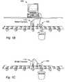
- FIGS. 1 B and 1 CImage Processing Systems
- FIGS. 1B and 1Cillustrate image processing or machine vision systems according to various embodiments of the invention.
- the image processing system of FIG. 1Bmay comprise a computer 102 and a smart camera 110 , and may further include a motion control device 192 .
- the image processing system of FIG. 1Cmay comprise smart camera 110 and motion control device 192 , and may not include computer system 102 .
- the smart camera 110may include a digital camera that acquires a digital video signal which comprises an image, or a sequence of images, or other data desired to be acquired.
- the smart camera 110may instead include an analog camera that acquires an analog video signal, and the smart camera 110 may further include A/D converters for converting the analog video signal into a digital image.
- the smart camera 110may include a functional unit configured according to a program, e.g., a text-based or graphical program.
- the functional unitmay be configured to perform an image processing function as represented by a graphical program.
- a graphical (or text-based) programmay have been first created to perform the image processing function, such as with a graphical development environment on the computer system 102 , and the graphical program may then have been deployed onto the functional unit of the smart camera to implement the image processing function.
- the digital video signal or digital imagemay be provided to the functional unit in the smart camera 110 , wherein the image processing function is performed.
- the functional unit in the smart camera 110may perform a first portion of the image processing function, and the computer 102 may perform a second portion of the image processing function.
- the functional unit in the smart camera 110may perform the actual processing of the image to determine characteristics of the image, and the computer 102 may then perform an operation based on this result, such as rejecting a part from an assembly line, or logging the results to file.
- the functional unit in the smart camera 110may perform the processing of the image to determine characteristics of the image, and may also optionally perform an operation based on this result, and the computer system 102 may execute software to provide a user interface for the system, e.g., the computer system 102 may execute a user interface portion of a graphical program, where the block diagram of the graphical program is used to configure the functional unit in the smart camera 110 .
- a first portion of the graphical programe.g., DSP functions requiring real time performance
- the smart camerai.e., the functional unit or a function module 108 comprised in the smart camera 110
- a second portion of the graphical programe.g., a user interface where real time performance is not required, may be executed by the computer system 102 .
- the functional unit and/or the function module 108 in the smart camera 110may perform all of the desired image processing function, including optionally performing an operation based on determined characteristics of the image, and hence the computer system 102 may not be necessary during operation of the system.
- the smart camera 110may include a processor and memory (in addition to the functional unit which executes the image processing function) which may execute the second portion of the graphical program, e.g., the user interface portion.
- a function module 108may execute the user interface portion of the program.
- the functional unit in the smart camera 110may control the motion control device 192 .
- Examples of motion control functionsinclude moving a part or object to be imaged by a camera, rejecting a part on an assembly line, or placing or affixing components on a part being assembled, or a robotics application, among others.
- FIG. 1 DBlock Diagram of an Image Acquisition System
- FIG. 1Dis a block diagram of an image acquisition system, according to another embodiment of the invention.
- the smart camera 110may be coupled to computer system 102 via a network (e.g., the Internet) 104 as shown, or, as mentioned above, may be coupled to the computer system 102 by other transmission means, including serial or parallel bus, wireless, and CAN, among others.
- the smart camera 110may include a functional unit 106 , e.g., a processor and memory and/or a programmable hardware element, such as an FPGA, which may be operable to perform image processing and/or analysis on an acquired image.
- a functional unit 106e.g., a processor and memory and/or a programmable hardware element, such as an FPGA, which may be operable to perform image processing and/or analysis on an acquired image.
- the functional unit 106may be programmed by computer system 102 , thus, the smart camera 110 may be re-configurable, i.e., programmable by an external computer system. Additionally, the smart camera 110 may include one or more function modules 108 , which may be operable to perform a variety of functions, such as image processing, pattern recognition, I/O functions, and network communications, among others.
- function modules 108may be inserted into slots of the smart camera to configure the smart camera for desired operations.
- the smart camera 110 together with the function module(s) 108may operate as a measurement or control device.
- the function modulemay be operable to couple to a sensor, where the sensor is operable to send sensor signals to the function module for one or more of signal conditioning and signal conversion.
- the signal conditioningmay include one or more of protection, isolation, filtering, amplification, and excitation.
- the signal conversionmay include one or more of analog to digital (A/D) conversion and digital to analog (D/A) conversion.
- the function module 108may be operable to perform signal conditioning and/or signal conversion on signals sent by a sensor coupled to the function module 108 (not shown), and to transmit results of such processing on to the smart camera 110 .
- the function module 108may include a sensor as well as the signal conditioning and/or conversion logic, and so the function module may be operable to perform one or more of signal conditioning and signal conversion on sensor signals received from the sensor comprised on the function module 108 .
- One or more of the function modules 108may include a functional unit, such as a processor and memory, or an FPGA.
- the function modulemay operate to provide co-processing functionality to the smart camera.
- the function modulemay perform an image processing function, such as pattern matching, blob analysis, edge detection, etc., on an acquired image.
- image processing functionsuch as pattern matching, blob analysis, edge detection, etc.
- dedicated processing functionsmay be provided by the function module(s) which may exceed the capabilities of the smart camera functional unit.
- multiple function modules 108may be used in conjunction to perform image processing, measurement, and/or control tasks.
- a first function module 108may include a sensor, such as a thermocouple, pressure sensor, or strain gauge, while a second function module 108 may perform signal conditioning and/or conversion on signals received from the first function module 108 .
- the smart camera 110may communicate with both the first and the second function modules 108 and perform an action, such as generating an image, based on signals received from both the first and the second function modules 108 .
- a function module 108may receive signals from a temperature sensor and perform signal conditioning and/or signal conversion on the signals to generate a scaled temperature value.
- the temperature valuemay be transmitted to the functional unit 106 on the smart camera 110 which may compare the value to a threshold, and if the value exceeds the threshold, the smart camera may generate/capture an image.
- the function modulemay perform an image processing function on the acquired image, as noted above.
- a function module 108may comprise a sensor, such as a photometer or light meter, which operates to ascertain ambient conditions for the smart camera 110 , such as brightness.
- the smart camera 110may use readings from the sensor to set parameters for image capture, such as shutter speed, in order to optimize image quality.
- a function module 108may comprise a motion detector which may be operable to send a trigger to the smart camera 110 when motion is detected, thus causing an image of the moving phenomenon to be generated.
- the smart camera 110may be operable to receive data from the function module 108 and communicate the data (possibly in a different format or form) to the computer system 102 , e.g., over the network 104 .
- the smart camera 110may receive signal data in a proprietary format from the function module 108 and format the data for transmission over wireless Ethernet to the computer system 102 .
- the function module 108may provide network communication functionality to the smart camera, thereby allowing the smart camera 110 to send image data to external systems or to publish image data on a website, for example.
- a function module 108may include a functional unit or control logic which may be operable to control an actuator, such as a stepping motor, to perform a motion task.
- the smart camera 110may analyze image information and communicate results to the function module 108 , and thus may use the function module 108 to perform a machine vision task.
- function modules 108may perform such tasks as timing, alarms, logging, synchronization, etc.
- the function modules 108may provide synchronization functions to the smart cameras 110 , thereby facilitating coordinated operation of the plurality of smart cameras 110 .
- one of the smart cameras 110may operate as a master unit, while the other smart cameras 110 operate as slaves, where the smart cameras' 110 respective function modules 108 provide the synchronization functionality as appropriate depending on the master/slave status of the smart camera 110 .
- each of the plurality of smart cameras 110may operate as a peer, where the function modules 108 coordinate the respective smart camera 110 operations in a peer-to-peer manner.
- a plurality of smart cameras 110may be coupled to each other via a network, e.g., through wireless means, thereby implementing a distributed machine vision, where the communication and/or coordination functionality is provided at least in part by the smart cameras' 110 respective function modules 108 .
- multiple smart cameras 110may each acquire an image of an object, then collectively analyze the different images of the object to generate three dimensional information about the object.
- the function module 108may comprise connectivity to one or more other smart cameras 110 , providing for coordinated operations between the smart camera 110 and the one or more other smart cameras 110 .
- the function modulemay include a gyroscope which may stabilize the smart camera, allowing for precise control of the camera's orientation.
- the function modulemay have a small form factor which may enable deployment of the smart camera with minimal space requirements.
- the smart camera 110may be operable to receive interface protocol information from the function module 108 specifying how to operate or interface with the function module 108 .
- the smart camera 110may then communicate the interface protocol information to the computer system 102 and, based on the interface protocol information, the computer system 102 may program or configure the functional unit 106 on the smart camera 110 to implement the interface as specified by the function module 108 .
- the function module 108may tell the smart camera 110 how to communicate, and the smart camera 110 may then tell the computer system 102 how to program the smart camera 110 to communicate with the function module 108 accordingly.
- the computer system 102may then program the smart camera 110 (i.e., the smart camera's 110 functional unit 106 ), thereby implementing the interface specified in the interface protocol information communicated by the function module 108 . This process may be referred to as initialization of the function module/smart camera.
- the smart camera 110 , function module 108 , and/or the computer 102may include a memory medium on which computer programs, e.g., text based and/or graphical programs, according to the present invention may be stored.
- a memory mediummay also be located on a second computer which is coupled to the system through a network, such as a local area network (LAN), a wide area network (WAN), or the Internet.
- the second computermay operate to provide the program instructions through the network to the system (i.e., the smart camera 110 , the function module 108 , and/or the computer 102 ) for execution.
- the computer system 102may take various forms, including a personal computer system, mainframe computer system, workstation, network appliance, Internet appliance, personal digital assistant (PDA), television set-top box, instrument, or other device.
- PDApersonal digital assistant
- the term “computer system”can be broadly defined to encompass any device having at least one processor which executes instructions from a memory medium.
- the computer system 102may also store a program implementing one or more image processing, control, and/or measurement functions, e.g., a software program, such as a text-based or graphical program, implementing the one or more functions.
- the term “measurement function”may include measurement and/or data acquisition, such as displaying received data, analyzing and/or processing received data to generate a result, performing signal processing on received data, or otherwise analyzing and/or processing received data to perform a measurement.
- the computer system 102may be operable to execute the program to perform the one or more functions, preferably in conjunction with operation of the smart camera 110 and/or function module 108 .
- the programmay be executable to perform one or more of image processing, DAQ, measurement, or control functions, including analysis of image data or signals received from the smart camera, control of smart camera and/or function module operations, user interface functions, and pattern recognition and/or characterization, among others.
- the computer system 102may be operable to deploy the program onto the functional unit 106 of the smart camera 110 .
- the computer system 102may download the program onto the functional unit 106 of the smart camera 110 , after which the smart camera 110 may be operable to execute the program to perform the one or more functions, preferably in conjunction with operation of the function module 108 , and possibly the computer system 102 .
- the computer system 102may be operable to deploy the program onto the function module 108 of the smart camera 110 .
- the function module 108may be programmable by a user (e.g., using the computer system 102 ) to perform any of a variety of functions.
- a function module 108may be operable to program the smart camera 110 to perform one or more functions.
- a function module 108may be operable to receive a program from the computer system 102 , and program the functional unit 106 of the smart camera 110 to perform the function.
- the function module 108may program the smart camera 110 to perform a first portion of a function while the function module 108 performs a second portion of the function.
- the configured smart camera 110 and the function module 108may then be operable to perform image acquisition/processing and/or control operations, optionally using the computer system 102 .
- function modules 108may provide a wide variety of functions which may extend the flexibility and utility of the smart camera 110 and therefore expand the applications thereof.
- FIGS. 2 A and 2 BImage Acquisition System having a Smart Camera
- FIGS. 2A and 2Billustrate an image acquisition system with a smart camera 110 .
- the smart camera 110may include a housing which encloses a portion or all of the smart camera 110 components, or may be comprised on a frame which primarily provides structural support for the smart camera 110 components.
- a camera 282may be attached directly to the housing.
- the housingmay have a plurality of sides.
- the plurality of sidesmay comprise top, bottom, left, right, front and back sides. Therefore, the smart camera 110 may include a housing having a plurality of sides and a camera 282 directly attached to the housing for acquiring an image of an object.
- FIG. 2 AImage Acquisition System with Smart Camera
- FIG. 2Aillustrates an image acquisition system comprising computer system 102 coupled to the smart camera 110 .
- the smart camera 110is an example of an image acquisition device.
- the term “smart camera”is intended to include any of various types of devices that include a camera 282 or other image sensor and a functional unit 106 capable of being configured to perform an image processing function to analyze or process an acquired image.
- the computational load of vision algorithmsmay be circumvented or mitigated by merging low level processing with the camera or sensor in a single module.
- a hardware architecturemay be defined in a Hardware Description Language (e.g., VHDL), simulated and synthesized into digital structures that can then be configured in a Field Programmable Gate Array (FPGA).
- VHDLHardware Description Language
- FPGAField Programmable Gate Array
- the flexibility of an FPGAmay be combined with a sensor for real time image processing.
- the flexibility of a processor and memorymay be combined with a sensor for real time image processing.
- the smart camera 110may include function modules 108 which may be operable to provide a variety of image processing, I/O, control, automation, and/or communication functions to the smart camera 110 .
- the computer system 102 shown in FIG. 2Amay include a memory medium.
- the memory mediummay store a development environment, such as a graphical programming development system, for developing programs for execution by the functional unit 106 on the smart camera 110 , or by a function module 108 comprised therein.
- a graphical programming development systemmay be used to develop a graphical program that implements an image processing function.
- the smart camera 110may include a functional unit 106 , which may be a programmable hardware element (programmable or reconfigurable hardware), e.g., an FPGA, and/or a processor and memory.
- the functional unit 106 in the smart camera 110may be configured with a program that implements the image processing function.
- the smart camera 110may also comprise a camera 282 coupled to the functional unit 106 .
- the smart camera 110may also include a memory (a memory medium) coupled to the camera 282 for storing an acquired image. If the smart camera 110 includes an analog camera, the smart camera 110 may further include analog to digital (A/D) logic for converting analog image signals into a digital image for storage in the memory.
- the smart camera 110may also optionally include timer/counter logic that may perform timing/counting operations, e.g., during operation of the functional unit 106 .
- the smart camera 110may include a housing which encloses some or all of the components of the smart camera 110 .
- the camera 282may be included in the housing.
- the housingmay be ruggedized, i.e., adapted for industrial use.
- the housingmay comprise a Personal Digital Assistant (PDA).
- PDAPersonal Digital Assistant
- the functional unit 106may be comprised in the housing and coupled to the camera 282 , where the functional unit 106 is configurable to implement an image processing function.
- a backplanemay also be comprised in the housing, where the backplane is coupled to the functional unit 106 and is operable to provide for electrical communication.
- One or more slotsmay also be comprised in the housing, where each of the one or more slots includes a connector that is electrically coupled to the backplane, and where each of the one or more slots is adapted for receiving a function module 108 .
- the one or more slotsmay comprise a plurality of slots, i.e., two or more slots.
- the housinghas dimensions less than about 1 foot by about 1 foot by about 1 foot. In another embodiment, the housing has dimensions less than about 1 foot by about 8 inches by about 8 inches. In yet another embodiment, the housing has dimensions less than about 6′′ by about 6′′ by about 6′′.
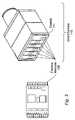
- FIG. 2 BSmart Camera
- FIG. 2Billustrates another embodiment of a smart camera 110 .
- the smart cameraincludes a camera 282 , coupled to circuitry/logic (e.g., one or more circuit boards) for performing various image processing and/or acquisition functions.
- the circuitry/logicmay include a functional unit 106 , such as a programmable hardware element, e.g., an FPGA and/or a processor and memory.
- the functional unit 106 in the smart camera 110may be configured with a program that implements the image processing function, and may also include a memory coupled to the camera 282 for storing an acquired image.
- the smart camera 110may further include analog to digital (A/D) logic for converting analog image signals into a digital image for storage in the memory.
- A/Danalog to digital
- the functional unit 106may be operable to provide signal conditioning on signals from the analog camera. In another embodiment, the functional unit 106 may be operable to provide signal conversion on signals from the analog camera.
- the smart camera 110may also optionally include timer/counter logic that may perform timing/counting operations, e.g., during operation of the programmable hardware element.
- the smart camera 110may also include various I/O ports for communicating with external devices, such as computer system 102 .
- the smart camera 110may include a frame or structure to support the components comprised in the smart camera 110 .
- the smart camera 110may include a “PC-on-a-Card” which may provide part or all of the functionality of a personal computer.
- the smart camera 110may include a chassis 111 which includes a plurality of expansion slots for receiving function modules 108 .
- the function modules 108may thus provide a mechanism for expanding the capabilities of the smart camera 110 in an easy modular fashion.
- the smart camera 110may also include a function module 108 comprised in one of the slots, which may provide modular functionality to the smart camera 110 .
- the function module 108may provide dedicated image processing, including one or more of pattern recognition, Fourier analysis (or other transform analysis), motion detection; communication functionality, such as wired and/or wireless network connectivity, e.g., Ethernet and Internet network connectivity, USB connectivity, and Firewire (IEEE 1134) connectivity, among others.
- the function modulemay be programmable over a network, such as by a computer system 102 .
- the functional unit 106may be programmable by the function module 108 to perform an image processing function.
- the functional unit 106 comprised in the smart camera 110may be programmable over a network.
- FIG. 4A block diagram of an exemplary embodiment of the smart camera 110 is shown in FIG. 4 , described below.
- FIG. 3Smart Camera with Chassis and Function Modules
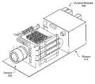
- FIG. 3illustrates an embodiment of the invention where each function module 108 is in the form of a cartridge and the smart camera 110 includes the chassis 111 , also referred to as a cartridge carrier, which may be operable to receive one or more of the function modules 108 .
- the chassis 111may be operable to receive a plurality of the function modules 108 .
- the chassis 111may include a backplane which provides for electrical communication, and one or more slots for receiving the function modules 108 .
- the backplanemay comprise a bus for communication with function modules 108 , including one or more of ISA, EISA, PCI, SPCI, PCI-X, CompactPCI, PXI, VXI, VMEbus, PC/104, PC/104 Plus, SCXI, PCMCIA, CardBus, PMC (PCI Mezzanine Card), MicroDAQ, Smart Card, CompactFlash, 3GIO, and USB, among others.
- the function modulesmay each have a form factor in accordance with a corresponding one of ISA, EISA, PCI, SPCI, PCI-X, CompactPCI, PXI, VXI, VME, PC/104, PC/104 Plus, SCXI, PCMCIA, PC Card, PMC (PCI Mezzanine Card), MicroDAQ, Smart Card, CompactFlash, 3GIO and USB.
- Each of the one or more slotsmay include a connector that is coupled to the backplane, where each of the one or more slots may be adapted for receiving one of the function modules 108 .
- the smart camera 110may host a plurality of function modules 108 , each of which may provide DAQ, image processing/analysis, and/or control functionality for an image processing or control operation or task, among others.
- the chassis 111may include one or more carriers which are able to convert function module 108 signals to standard bus/network signals, and implement power-on states, plug and play, and/or watchdogs, these features being well known in the art.
- Example carriersmay include, but are not limited to, 4-slot Ethernet carrier, 4-slot and 1-slot USB carrier, multi-slot RIO carrier, 1-slot wireless carrier, and CAN carrier, among others.
- the smart camera 110may be operable to communicate with each function module 108 and be programmed or configured (e.g., by a computer system 102 ) to implement the respective interface of each function module 108 .
- a suite of sensorsmay be fielded, each of which feeds signals to a respective function module 108 which in turn communicates through a respective interface (protocol) with the smart camera 110 .
- the smart camera 110may support a heterogeneous plurality of interfaces without having to include a heterogeneous set of interface hardware components.
- the function modules 108may be easily removed, added, and replaced. In other words, function modules 108 may be exchanged to change the configuration or capabilities of the smart camera 110 .
- the function module 108may be replaced without powering down the smart camera 110 , i.e., the function module 108 may be “hot-plugged” into the smart camera 110 , where the smart camera 110 and inserted function module 108 may operate without requiring a reboot. In other words, any initialization required may be performed without a reboot.
- the function module 108may communicate the interface protocol information to the smart camera 110 upon attachment, and the smart camera 110 may be programmed in response, as described above.
- the function module 108 and/or smart camera 110may require a reboot or reset after attachment to perform the initialization.
- a new function module 108may be added (i.e., inserted or attached) to the smart camera 110 .
- the smart camera 110may automatically perform the initialization with respect to the new function module 108 .
- the new function module 108may communicate respective interface information to the smart camera 110 , which may then be programmed (e.g., by the computer system 102 ) to implement the respective interface, thereby enabling operations with the new function module 108 .
- the new function module 108itself may program the smart camera 110 with the appropriate interface.
- the new function module 108may replace another function module 108 which was removed during operation of the smart camera 110 .
- the function module 108may provide functionality including one or more of signal conditioning, ADC, microprocessor, and optional isolation, for sensor to digital operations. Additionally, in one embodiment, the new function module 108 may provide a PXI interface, and Electronic Data Sheet (EDS)/calibration history on board. In one embodiment, the function module 108 may have a small form factor. For example, in one embodiment, the function module 108 may have dimensions less than or equal to approximately 1 inch by 2 inches by 3 inches. In one embodiment, the function module may have dimensions of approximately 0.2 inches by 1 inch by 1 inch or more. Thus, in a preferred embodiment, the function module 108 has a compact form factor which may enable deployment of the smart camera 110 with minimal space requirements.
- EDSElectronic Data Sheet
- the function modules 108may provide communication, integrated signal conditioning, optional isolation, support for plug and play sensors (IEEE 1451.4), modular image processing, control functionality, and easy use and configuration, among other functions. Additionally, the function modules 108 may be rugged, i.e., may be suitable for industrial use. In various embodiments, the function modules 108 may plug into one or more of an Ethernet carrier, a USB carrier, an Ethernet Vision I/O slot, a PXI carrier, a PCI carrier, handhelds, DAQ in the cable, and RIO devices (e.g., panelettes), among others.
- function modules 108include, but are not limited to, DSP (Digital Signal Processing), ASP (Analog Signal Processing), displays, GUI's, thermocouples, analog (e.g., 10 V) inputs, fast analog inputs allowing vibration analysis, analog output (e.g., 1V to 10V), digital input (e.g., 5V to 30V), digital output (e.g., 5V to 30V), analysis, decision-making, pattern recognition, and stabilization.
- DSPDigital Signal Processing
- ASPAnalog Signal Processing
- displaysGUI's
- thermocouplesanalog (e.g., 10 V) inputs
- analog outpute.g., 1V to 10V
- digital inpute.g., 5V to 30V
- digital outpute.g., 5V to 30V
- analysisdecision-making, pattern recognition, and stabilization.
- FIG. 4 AComputer System Block Diagram
- FIG. 4Ais an exemplary block diagram of one embodiment of the computer system 102 illustrated in FIGS. 1A-1D and FIG. 2A . It is noted that any type of computer system configuration or architecture can be used as desired, FIG. 4A illustrating a representative PC embodiment.
- the computer system 102may be a general purpose computer system, a computer implemented on a PXI card installed in a PXI chassis, a computer implemented on a VXI card installed in a VXI chassis, or other type of computer system.
- the elements of a computernot necessary to understand the present invention have been omitted from FIG. 4A for simplicity.
- the computer system 102preferably includes at least one central processing unit or CPU 160 which is coupled to a processor or host bus 162 .
- the CPU 160may be any of various types, including an x86 processor, e.g., a Pentium class, a PowerPC processor, a CPU from the SPARC family of RISC processors, as well as others.
- Main memory 166is coupled to the host bus 162 by means of memory controller 164 .
- the main memory 166may store software according to one embodiment of the present invention, e.g., image processing software.
- the main memory 166may also store operating system software, i.e., software for operation of the computer system, as is well known to those skilled in the art.
- the host bus 162may couple to an expansion or input/output bus 170 by means of a bus controller 168 or bus bridge logic.
- the expansion bus 170is preferably the PCI (Peripheral Component Interconnect) expansion bus, although other bus types may be used.
- the expansion bus 170may include slots for a plurality of devices including a smart camera 110 with inserted function module(s) 108 , as well as various other devices such as a motion control interface card 138 , a video display subsystem 180 and hard drive 182 coupled to the expansion bus 170 .
- FIG. 4Aalso illustrates several exemplary ways of coupling of the smart camera 110 to the computer system 102 .
- the smart camera 110may be coupled to the computer system 102 via the expansion bus 170 .
- the smart camera 110may be coupled to the computer system 102 via a network, thus, the computer 102 may also include a network interface 107 to facilitate communication between the smart camera 110 and the computer 102 .
- the smart camera 110may be coupled to the computer system through a function module 108 , which in turn may be coupled to the computer system 102 via the expansion bus 170 or the network interface 107 .
- FIG. 4 BSmart Camera Block Diagram
- FIG. 4Bis a block diagram of a smart camera 110 with programmable hardware.
- this embodimentuses a combination of processor/memory and programmable hardware 206 , e.g., FPGA, to perform image processing (and/or other) functions.
- the programmable hardware 206 element in the smart camera 110may be configurable to perform an image processing function on an acquired image. It should be noted that this embodiment is meant to be illustrative only, and is not intended to limit the architecture, components, or form of the smart camera 110 .
- the embodiment of the smart camera 110 illustrated in FIG. 4Bincludes a camera 282 and a functional unit 106 .
- the functional unit 106may comprise a programmable hardware element 206 , e.g., a field programmable gate array (FPGA) such as those available from Xilinx, Altera, etc., and may also comprise a processor 212 and memory 214 .
- the programmable hardware element 206 , processor 212 and memory 214may each be coupled to the camera 282 and/or to an image memory 284 .
- the smart camera 110may also include a non-volatile memory 288 coupled to the programmable hardware element 206 , the processor 212 , the memory 214 and the image memory 284 .
- the non-volatile memory 288may be operable to store a hardware description and/or program received from the computer system 102 to enable execution of the functional unit 106 prior to or during booting of the computer system 102 .
- the smart camera 110may also include an I/O connector 220 which is operable to send and receive signals.
- the I/O connector 220may present analog and/or digital connections for receiving/providing analog or digital signals.
- the I/O connector 220may enable the smart camera 110 to communicate with computer system 102 to receive a program for performing image processing (and/or other) functions.
- a programcan be created on the computer system 102 , or on another computer in a networked system, and at least a portion of the program can be deployed onto the functional unit 106 of the smart camera 110 , and/or a function module 108 (e.g., 108 A, 108 B, or 108 C) comprised in the smart camera 110 .
- a function module 108e.g., 108 A, 108 B, or 108 C
- the smart camera 110may include a dedicated on-board processor 212 and memory 214 in addition to the programmable hardware element 206 .
- Thisenables a first portion of the program to be compiled into machine language for storage in the memory 214 and execution by the processor 212 (i.e., to execute natively). This may be in addition to a second portion of the program being converted into a hardware implementation form in the FPGA 206 .
- the first portion of the graphical programmay be compiled for execution on the on-board processor 212 and executed locally on the smart camera 110 via the processor 212 and memory 214 , and the second portion of the program may be translated or converted into a hardware executable format and uploaded to the FPGA 206 for hardware implementation.
- one or more function modules 108may be operable to execute a portion or all of the program to perform the function.
- the smart camera 110 functional unit 106may comprise one or more processors 212 , one or more programmable hardware elements 206 , or any combination of the two, as desired.
- the function modules 108may include functional units 106 as required to perform their specified functions.
- the smart camera 110may include image memory 284 which couples to the programmable hardware 206 , the camera 282 , the processor 212 , memory 214 , bus interface 216 , the control/data bus 218 , and a local bus 217 .
- the image memory 284may be operable to store a portion of an image, or one or more images received from the camera 282 .
- the image memory 284may enable the programmable hardware 206 and/or the processor 212 to retrieve the one or more images, operate on them, and return the modified images to the image memory 284 .
- one or more of the function modulesmay be operable to retrieve the image from the image memory 284 , operate on the image, and return the (possibly) modified image to the image memory 284 .
- the imagesmay be retrievable for transmission to external systems, such as the computer system 102 , via the I/O connector 220 .
- the smart camera 110may further include bus interface logic 216 and a control/data bus 218 .
- the smart camera 110 and/or a function module 108may comprise a PCI bus-compliant interface card adapted for coupling to the PCI bus of the host computer 102 , or adapted for coupling to a PXI (PCI extensions for Instrumentation) bus.
- the bus interface logic 216 and the control/data bus 218thus present a PCI or PXI interface.
- the smart camera 110may also include local bus interface logic 217 .
- the local bus interface logic 217may present a RTSI (Real Time System Integration) bus for routing timing and triggering signals between the smart camera 110 and one or more other devices or cards, such as other smart cameras 110 , motion control devices 136 , and/or smart sensors.
- RTSIReal Time System Integration
- the RTSI busmay provide for timing and triggering between the smart camera 110 and one or more function modules 108 . In one embodiment, the RTSI bus may provide for timing and triggering between smart camera 110 and one or more devices coupled to the one or more function modules.
- the one or more devicesmay include any of one or more smart cameras 110 , one or more motion control devices 136 , and/or one or more smart sensors, among others.
- the RTSI busmay provide for timing and triggering between two or more function modules 108 .
- the RTSI busmay provide for timing and triggering between two or more devices coupled to said two or more function modules 108 .
- Each of the two or more devicesmay comprise one or more of a smart camera 110 , a motion control device 136 , and a smart sensor, among others.
- the smart camera 110may include data acquisition (DAQ) logic, not shown, such as analog to digital (A/D) converters, digital to analog (D/A) converters, timer counters (TC) and signal conditioning (SC) logic. Some or all of the DAQ logic may be provided by one or more of the function modules 108 . The DAQ logic may be useful for signal processing and motion control applications. The programmable hardware element or FPGA 206 may access these resources directly, thereby enabling creation of very powerful measurement, DSP and control applications, among others. For example, if the camera 282 is an analog camera, the smart camera 110 may further include analog to digital (A/D) logic (not shown) for converting analog image signals into a digital image for storage in the memory 214 .
- A/Danalog to digital
- TCdigital to analog
- SCsignal conditioning
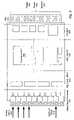
- FIG. 5Function Module Hardware Layout
- FIG. 5illustrates one embodiment of a hardware layout of a function module 108 .
- FIG. 5only illustrates the functional components of the functional module 108 , and that in the preferred embodiment, a housing or chassis may be included for enclosure, protection, or support of the module components.
- the function module 108 illustrated in FIG. 5is meant to be exemplary only, and is not intended to limit the form or function of the function module to any particular embodiment.
- a printed wiring boardmay include a functional unit 106 , such as a processor/memory 212 / 214 and/or a programmable hardware element, such as an FPGA 206 .
- the functional unit 106may operate to perform any of various image processing/analysis functions.
- the functional unit 106may operate to perform various other functions related to the operation of the smart camera 110 , including I/O functions, communication functions, control functions, measurement functions, and GPS functions, among others.
- the PWBmay be equipped with signal input terminals 301 for receiving analog inputs 310 , e.g., from a sensor.
- a subset of the input terminals 301may be used to receive an optional Transducer Electronic Data Sheet (TEDS) 410 describing the functionality of a transducer (e.g., sensor) in machine-readable form.
- TMSTransducer Electronic Data Sheet
- the PWB of the function module 108may further include signal conditioning logic or circuitry 302 , such as signal conditioners, multi-plexers (MUXs), etc. which may be operable to receive the signals from the analog inputs 310 and perform signal conditioning on the signals, as is well known in the art.
- signal conditioning logic or circuitry 302such as signal conditioners, multi-plexers (MUXs), etc. which may be operable to receive the signals from the analog inputs 310 and perform signal conditioning on the signals, as is well known in the art.
- the PWBmay also include signal conversion logic or circuitry 304 , such as the ADC shown, which may be operable to receive the conditioned signals from the signal conditioning circuitry 302 and perform any of various signal conversion operations on the signals.
- the ADC 304may operate to convert the conditioned analog signals to digital signals.
- other signal conversionsmay be performed as desired.
- the functional unit 106may provide an interface between signal conditioning/conversion components 302 / 304 and external systems, such as computer system 102 . As also mentioned above, the functional unit 106 may be operable to communicate interface protocol information to a smart camera 110 indicating how to communicate with and operate the function module 108 .
- isolation circuitry 305may also be included on the PWB which may be operable to protect the components of the function module from spurious signals, signal noise, harmful voltage and/or current surges, impedance mismatches, and the like.
- the PWBmay also include terminals for communicating with external systems such as the computer system 102 , including PXI 316 , trigger line(s) 314 , power 312 and ground 318 lines, among others.
- the function module 108may perform any of a wide variety of functions for the smart camera 110 .
- Such functionsmay include, but are not limited to, measurement, image processing, communication, and control functions.
- the function module 108may comprise an industrial programmable logic controller including one or more of a real time controller and an embedded controller.
- the function module 108may comprise a motion control module for controlling servo or stepper motors.
- the function module 108may comprise a web server, and where the smart camera is operable to publish data to a website.
- the function module 108may comprise: a Global Positioning System (GPS) module for precise positioning with a satellite system; one or more of an Ethernet carrier, a USB carrier, a FireWire carrier, and a wireless carrier; one or more digital signal processing (DSP) processors for on-board hardware signal analysis; a data acquisition (DAQ) module for direct signal analysis and conditioning; a GPIB module for connectivity to GPIB instruments; an auxiliary power source for the smart camera 110 , such as a battery pack or solar generator; a display for the smart camera 110 , such as an LCD display; a Graphical User Interface (GUI) for the smart camera 110 ; and/or a printer for the smart camera 110 , among others.
- the function module 108may also include mechanical components.
- the function module 108may include one or more gyroscopes for stabilizing the smart camera.
- a smart camera 110which includes a plurality of slots may utilize one or more function modules 108 inserted into the slots to perform a wide variety of functions, including one or more of I/O, network communications, synchronization, image processing and analysis, pattern recognition, GPS, control, measurement, signal conditioning and/or conversion, timing, triggering, display, interface, and/or any other function useful in smart camera 110 operations.
- function modules 108inserted into the slots to perform a wide variety of functions, including one or more of I/O, network communications, synchronization, image processing and analysis, pattern recognition, GPS, control, measurement, signal conditioning and/or conversion, timing, triggering, display, interface, and/or any other function useful in smart camera 110 operations.
Landscapes
- Engineering & Computer Science (AREA)
- Multimedia (AREA)
- Signal Processing (AREA)
- Software Systems (AREA)
- Studio Devices (AREA)
Abstract
Description
Claims (63)
Priority Applications (3)
| Application Number | Priority Date | Filing Date | Title |
|---|---|---|---|
| US10/120,151US7327396B2 (en) | 2002-04-10 | 2002-04-10 | Smart camera with a plurality of slots for modular expansion capability through a variety of function modules connected to the smart camera |
| US11/857,041US7532249B2 (en) | 2002-04-10 | 2007-09-18 | Smart camera with a plurality of slots for modular expansion capability through a variety of function modules connected to the smart camera |
| US12/426,268US7791671B2 (en) | 2002-04-10 | 2009-04-19 | Smart camera with modular expansion capability including a function module that performs image processing |
Applications Claiming Priority (1)
| Application Number | Priority Date | Filing Date | Title |
|---|---|---|---|
| US10/120,151US7327396B2 (en) | 2002-04-10 | 2002-04-10 | Smart camera with a plurality of slots for modular expansion capability through a variety of function modules connected to the smart camera |
Related Child Applications (1)
| Application Number | Title | Priority Date | Filing Date |
|---|---|---|---|
| US11/857,041ContinuationUS7532249B2 (en) | 2002-04-10 | 2007-09-18 | Smart camera with a plurality of slots for modular expansion capability through a variety of function modules connected to the smart camera |
Publications (2)
| Publication Number | Publication Date |
|---|---|
| US20030193571A1 US20030193571A1 (en) | 2003-10-16 |
| US7327396B2true US7327396B2 (en) | 2008-02-05 |
Family
ID=28790043
Family Applications (3)
| Application Number | Title | Priority Date | Filing Date |
|---|---|---|---|
| US10/120,151Expired - LifetimeUS7327396B2 (en) | 2002-04-10 | 2002-04-10 | Smart camera with a plurality of slots for modular expansion capability through a variety of function modules connected to the smart camera |
| US11/857,041Expired - LifetimeUS7532249B2 (en) | 2002-04-10 | 2007-09-18 | Smart camera with a plurality of slots for modular expansion capability through a variety of function modules connected to the smart camera |
| US12/426,268Expired - LifetimeUS7791671B2 (en) | 2002-04-10 | 2009-04-19 | Smart camera with modular expansion capability including a function module that performs image processing |
Family Applications After (2)
| Application Number | Title | Priority Date | Filing Date |
|---|---|---|---|
| US11/857,041Expired - LifetimeUS7532249B2 (en) | 2002-04-10 | 2007-09-18 | Smart camera with a plurality of slots for modular expansion capability through a variety of function modules connected to the smart camera |
| US12/426,268Expired - LifetimeUS7791671B2 (en) | 2002-04-10 | 2009-04-19 | Smart camera with modular expansion capability including a function module that performs image processing |
Country Status (1)
| Country | Link |
|---|---|
| US (3) | US7327396B2 (en) |
Cited By (34)
| Publication number | Priority date | Publication date | Assignee | Title |
|---|---|---|---|---|
| US20050212954A1 (en)* | 2004-03-26 | 2005-09-29 | Fuji Photo Film Co., Ltd. | Remote-shooting apparatus |
| US20060005160A1 (en)* | 1997-08-18 | 2006-01-05 | National Instruments Corporation | Image acquisition device |
| US20080007624A1 (en)* | 2002-04-10 | 2008-01-10 | Schultz Kevin L | Smart camera with a plurality of slots for modular expansion capability through a variety of function modules connected to the smart camera |
| US20100073493A1 (en)* | 2008-09-24 | 2010-03-25 | Michael Godfrey | Blast resistant video recording device |
| US20100165188A1 (en)* | 2008-12-29 | 2010-07-01 | Red.Com, Inc. | Modular digital camera |
| US20100165138A1 (en)* | 2008-12-29 | 2010-07-01 | Red.Com, Inc. | Modular motion camera |
| US20130050510A1 (en)* | 2011-08-29 | 2013-02-28 | Canon Kabushiki Kaisha | Image capture apparatus, accessory and image capture system |
| US20130147963A1 (en)* | 2005-12-06 | 2013-06-13 | Robert Bosch Gmbh | Modular surveillance camera system with self-identification capability |
| US20130250134A1 (en)* | 2012-02-19 | 2013-09-26 | Jack J. McCauley | System and Methods for Wireless Remote Control over Cameras |
| WO2014110748A1 (en)* | 2013-01-17 | 2014-07-24 | Abb Technology Ltd. | Motion controller and robot control system using the same |
| US9052740B2 (en) | 2013-03-12 | 2015-06-09 | Qualcomm Incorporated | Adaptive data path for computer-vision applications |
| US20150195442A1 (en)* | 2014-01-03 | 2015-07-09 | Lyve Minds, Inc. | Modular camera core control |
| US20150195432A1 (en)* | 2013-12-19 | 2015-07-09 | Lyve Minds, Inc. | Modular Camera Core |
| US9426339B2 (en)* | 2013-12-19 | 2016-08-23 | Lyve Minds, Inc. | Modular camera core and modular camera expansion system |
| US20160323483A1 (en)* | 2015-04-28 | 2016-11-03 | Invent.ly LLC | Automatically generating notes and annotating multimedia content specific to a video production |
| US9509904B2 (en) | 2014-04-23 | 2016-11-29 | Imperx, Inc. | User programmable image capturing and processing device |
| US9681028B2 (en) | 2013-03-15 | 2017-06-13 | Red.Com, Inc. | Digital camera with wireless connectivity |
| US20180054595A1 (en)* | 2015-02-19 | 2018-02-22 | Makoto Odamaki | Systems, methods, and media for modular cameras |
| US10116776B2 (en) | 2015-12-14 | 2018-10-30 | Red.Com, Llc | Modular digital camera and cellular phone |
| US10271031B2 (en) | 2014-04-04 | 2019-04-23 | Red.Com, Llc | Broadcast module for a digital camera |
| US10356291B2 (en) | 2008-07-07 | 2019-07-16 | Gopro, Inc. | Camera housing with integrated expansion module |
| US20190279355A1 (en)* | 2018-03-06 | 2019-09-12 | B&R Industrial Automation GmbH | Camera core of a smart camera for industrial image processing and method for industrial image processing |
| US10643271B1 (en)* | 2014-01-17 | 2020-05-05 | Glenn Joseph Bronson | Retrofitting legacy surveillance systems for traffic profiling and monetization |
| US10718996B2 (en) | 2018-12-19 | 2020-07-21 | Arlo Technologies, Inc. | Modular camera system |
| USD894256S1 (en) | 2018-08-31 | 2020-08-25 | Gopro, Inc. | Camera mount |
| USD905786S1 (en) | 2018-08-31 | 2020-12-22 | Gopro, Inc. | Camera mount |
| US10928711B2 (en) | 2018-08-07 | 2021-02-23 | Gopro, Inc. | Camera and camera mount |
| US11368621B2 (en)* | 2019-12-25 | 2022-06-21 | Canon Kabushiki Kaisha | Image capturing apparatus |
| USD991318S1 (en) | 2020-08-14 | 2023-07-04 | Gopro, Inc. | Camera |
| USD997232S1 (en) | 2019-09-17 | 2023-08-29 | Gopro, Inc. | Camera |
| USD1036536S1 (en) | 2017-12-28 | 2024-07-23 | Gopro, Inc. | Camera |
| US12321084B2 (en) | 2022-08-12 | 2025-06-03 | Gopro, Inc. | Interconnect mechanism for image capture device |
| US12379650B2 (en) | 2023-02-15 | 2025-08-05 | Gopro, Inc. | Reinforced image capture devices including interconnect mechanisms with a threaded accessory interface |
| USD1096914S1 (en) | 2024-03-15 | 2025-10-07 | Gopro, Inc. | Camera mount |
Families Citing this family (60)
| Publication number | Priority date | Publication date | Assignee | Title |
|---|---|---|---|---|
| US20030227554A1 (en)* | 2002-04-26 | 2003-12-11 | Nikon Corporation | Digital camera system |
| US9087380B2 (en)* | 2004-05-26 | 2015-07-21 | Timothy J. Lock | Method and system for creating event data and making same available to be served |
| US7813638B2 (en)* | 2004-06-07 | 2010-10-12 | Rudolph Technologies, Inc. | System for generating camera triggers |
| DE102004033481A1 (en)* | 2004-07-10 | 2006-01-26 | Robert Bosch Gmbh | Imaging system |
| US7073366B2 (en)* | 2004-09-16 | 2006-07-11 | Reservior Management (Barbados) Inc. | Method and apparatus to reduce the width of a slot or opening in a pipe, tube or other object |
| US20060092274A1 (en)* | 2004-11-04 | 2006-05-04 | Rockwell Automation Technologies, Inc. | Image sensor annotation method and apparatus |
| US20060210169A1 (en)* | 2005-03-03 | 2006-09-21 | General Dynamics Advanced Information Systems, Inc. | Apparatus and method for simulated sensor imagery using fast geometric transformations |
| US7982795B2 (en)* | 2005-04-11 | 2011-07-19 | Panayotis B. SPATHARIS | Image acquisition and exploitation camera system and methods therefore |
| JP2006344136A (en)* | 2005-06-10 | 2006-12-21 | Fanuc Ltd | Robot controller |
| DE102005046086A1 (en)* | 2005-09-26 | 2007-04-05 | Leutron Vision Gmbh | Electronic image recording system, has camera housing with housing cross section for camera module, where housing cross section and selected interface module are formed constant and offer for all modules uniform housing width and height |
| US20080177507A1 (en)* | 2006-10-10 | 2008-07-24 | Mian Zahid F | Sensor data processing using dsp and fpga |
| WO2008128205A1 (en) | 2007-04-13 | 2008-10-23 | Presler Ari M | Digital cinema camera system for recording, editing and visualizing images |
| US20080320408A1 (en)* | 2007-06-21 | 2008-12-25 | Dziezanowski Joseph J | Devices, Systems, and Methods Regarding Machine Vision User Interfaces |
| US20090009584A1 (en)* | 2007-07-03 | 2009-01-08 | Azurewave Technologies, Inc. | Wireless image signal transmission device |
| US7760238B2 (en)* | 2007-07-25 | 2010-07-20 | National Instruments Corporation | Vision system with deterministic low-latency communication |
| US20090086021A1 (en)* | 2007-09-27 | 2009-04-02 | Rockwell Automation Technologies, Inc. | Dynamically generating real-time visualizations in industrial automation environment as a function of contect and state information |
| EP2203794A4 (en)* | 2007-10-11 | 2011-08-24 | Direct Vision Control Oy | Use of a smart camera for controlling an industrial ac drive |
| US9325951B2 (en) | 2008-03-03 | 2016-04-26 | Avigilon Patent Holding 2 Corporation | Content-aware computer networking devices with video analytics for reducing video storage and video communication bandwidth requirements of a video surveillance network camera system |
| US8427552B2 (en)* | 2008-03-03 | 2013-04-23 | Videoiq, Inc. | Extending the operational lifetime of a hard-disk drive used in video data storage applications |
| US8773864B2 (en)* | 2008-06-18 | 2014-07-08 | Lockheed Martin Corporation | Enclosure assembly housing at least one electronic board assembly and systems using same |
| US8189345B2 (en)* | 2008-06-18 | 2012-05-29 | Lockheed Martin Corporation | Electronics module, enclosure assembly housing same, and related systems and methods |
| JP5397014B2 (en)* | 2009-05-21 | 2014-01-22 | ソニー株式会社 | Monitoring system, imaging device, analysis device, and monitoring method |
| KR20110064674A (en)* | 2009-12-08 | 2011-06-15 | 삼성전자주식회사 | Dynamic local function combination device and method |
| EP2333623A1 (en)* | 2009-12-11 | 2011-06-15 | Siemens Aktiengesellschaft | Monitoring system for data acquisition in a production environment |
| US9615147B2 (en)* | 2010-05-17 | 2017-04-04 | Flir Systems, Inc. | Multisensory meter system |
| US8572556B2 (en) | 2010-12-31 | 2013-10-29 | Starlims Corporation | Graphically based method for developing connectivity drivers |
| US8908013B2 (en) | 2011-01-20 | 2014-12-09 | Canon Kabushiki Kaisha | Systems and methods for collaborative image capturing |
| US8760538B2 (en)* | 2011-01-21 | 2014-06-24 | Exelis, Inc. | Adaptive gain control image processing system and method |
| US9560808B2 (en)* | 2011-04-19 | 2017-02-07 | Cnh Industrial America Llc | System for controlling bale forming and wrapping operations |
| US9665956B2 (en) | 2011-05-27 | 2017-05-30 | Abbott Informatics Corporation | Graphically based method for displaying information generated by an instrument |
| US9123002B2 (en) | 2011-05-27 | 2015-09-01 | Abbott Informatics Corporation | Graphically based method for developing rules for managing a laboratory workflow |
| CA2743016A1 (en)* | 2011-06-10 | 2012-12-10 | Hermary Opto Electronics Inc. | 3d machine vision scanning information extraction system |
| TWI448975B (en)* | 2011-07-15 | 2014-08-11 | Chunghwa Telecom Co Ltd | Dispersing-type algorithm system applicable to image monitoring platform |
| CN102244721A (en)* | 2011-07-18 | 2011-11-16 | 上海安添机电科技有限公司 | Integral intelligent industrial camera |
| WO2013055441A2 (en) | 2011-08-16 | 2013-04-18 | Unmanned Innovation Inc. | Modular flight management system incorporating an autopilot |
| EP2755073A4 (en)* | 2011-09-06 | 2015-04-15 | Fujifilm Corp | Television lens device |
| JP5895420B2 (en)* | 2011-09-21 | 2016-03-30 | セイコーエプソン株式会社 | Robot control device and robot system |
| US9268619B2 (en) | 2011-12-02 | 2016-02-23 | Abbott Informatics Corporation | System for communicating between a plurality of remote analytical instruments |
| WO2013100934A1 (en)* | 2011-12-28 | 2013-07-04 | Intel Corporation | Image stream pipeline controller for deploying image primitives to a computation fabric |
| US9200890B2 (en)* | 2012-05-22 | 2015-12-01 | Cognex Corporation | Machine vision systems and methods with predictive motion control |
| US10083496B2 (en)* | 2012-05-22 | 2018-09-25 | Cognex Corporation | Machine vision systems and methods with predictive motion control |
| KR102244153B1 (en)* | 2013-09-13 | 2021-04-23 | 엘지이노텍 주식회사 | Camera module |
| WO2015103210A1 (en)* | 2014-01-03 | 2015-07-09 | Lyve Minds, Inc. | Modular camera core and modular camera expansion system |
| CN105430255A (en)* | 2014-09-16 | 2016-03-23 | 精工爱普生株式会社 | Image processing device and robot system |
| US10110858B2 (en)* | 2015-02-06 | 2018-10-23 | Conduent Business Services, Llc | Computer-vision based process recognition of activity workflow of human performer |
| US9830297B2 (en)* | 2015-02-26 | 2017-11-28 | Spire Global, Inc. | Processor system for control of modular autonomous system |
| CN105511315B (en)* | 2015-12-01 | 2017-10-27 | 天津普达软件技术有限公司 | A kind of method for making Machine Vision Detection synchronous with controller holding |
| CN105472224B (en)* | 2016-01-05 | 2017-03-15 | 北京度量科技有限公司 | A kind of passive optical motion capture equipment and its application |
| KR102586962B1 (en)* | 2016-04-07 | 2023-10-10 | 한화비전 주식회사 | Surveillance system and controlling method thereof |
| EP3407593B1 (en) | 2017-05-24 | 2019-10-30 | Axis AB | Device, system and method for providing additional functionality to an apparatus |
| WO2019132852A1 (en)* | 2017-12-29 | 2019-07-04 | Олэг Лэонидовыч ДЫВИНЭЦЬ | Smart camera, information system and method of identifying free parking places in parking facilities having such a camera |
| JP6927078B2 (en)* | 2018-02-23 | 2021-08-25 | オムロン株式会社 | Sensor system, information processing device, sensor management method |
| JP7006369B2 (en)* | 2018-02-23 | 2022-01-24 | オムロン株式会社 | Sensor system, information processing device, sensor management method |
| JP7052550B2 (en)* | 2018-05-17 | 2022-04-12 | オムロン株式会社 | Image sensor |
| JP7425569B2 (en)* | 2019-09-20 | 2024-01-31 | キヤノン株式会社 | Imaging apparatus, device, control method and program |
| JP7325281B2 (en)* | 2019-09-20 | 2023-08-14 | キヤノン株式会社 | IMAGING DEVICE, CONTROL METHOD AND PROGRAM |
| ES2974215T3 (en)* | 2019-11-05 | 2024-06-26 | Schunk Sonosystems Gmbh | Ultrasonic welding device with integrated camera arrangement |
| EP3975119A1 (en)* | 2020-08-27 | 2022-03-30 | Canon Kabushiki Kaisha | Device, information processing apparatus, control method therefor, and program |
| CN115174802B (en)* | 2022-06-07 | 2023-12-29 | 杭州海康机器人股份有限公司 | Image acquisition card and image acquisition method |
| JP2024004272A (en)* | 2022-06-28 | 2024-01-16 | 株式会社キーエンス | controller |
Citations (47)
| Publication number | Priority date | Publication date | Assignee | Title |
|---|---|---|---|---|
| US5309556A (en) | 1986-03-07 | 1994-05-03 | Hewlett-Packard Company | Method for using interactive computer graphics to control electronic instruments |
| US5497498A (en) | 1992-11-05 | 1996-03-05 | Giga Operations Corporation | Video processing module using a second programmable logic device which reconfigures a first programmable logic device for data transformation |
| US5535342A (en) | 1992-11-05 | 1996-07-09 | Giga Operations Corporation | Pld connector for module having configuration of either first PLD or second PLD and reconfigurable bus for communication of two different bus protocols |
| US5541849A (en) | 1990-04-06 | 1996-07-30 | Lsi Logic Corporation | Method and system for creating and validating low level description of electronic design from higher level, behavior-oriented description, including estimation and comparison of timing parameters |
| US5583749A (en) | 1994-11-30 | 1996-12-10 | Altera Corporation | Baseboard and daughtercard apparatus for reconfigurable computing systems |
| US5603043A (en) | 1992-11-05 | 1997-02-11 | Giga Operations Corporation | System for compiling algorithmic language source code for implementation in programmable hardware |
| US5631974A (en) | 1990-08-31 | 1997-05-20 | Canon Research Centre Europe, Ltd. | Image processing |
| US5638299A (en) | 1995-06-22 | 1997-06-10 | Miller; Keith | Light weight, self-contained programmable data-acquisition system |
| US5652875A (en) | 1993-09-27 | 1997-07-29 | Giga Operations Corporation | Implementation of a selected instruction set CPU in programmable hardware |
| US5684980A (en) | 1992-07-29 | 1997-11-04 | Virtual Computer Corporation | FPGA virtual computer for executing a sequence of program instructions by successively reconfiguring a group of FPGA in response to those instructions |
| US5732277A (en) | 1986-10-24 | 1998-03-24 | National Instruments Corporation | Graphical system for modelling a process and associated method |
| US5737235A (en) | 1995-05-02 | 1998-04-07 | Xilinx Inc | FPGA with parallel and serial user interfaces |
| US5742504A (en) | 1995-11-06 | 1998-04-21 | Medar, Inc. | Method and system for quickly developing application software for use in a machine vision system |
| US5754227A (en)* | 1994-09-28 | 1998-05-19 | Ricoh Company, Ltd. | Digital electronic camera having an external input/output interface through which the camera is monitored and controlled |
| US5844606A (en)* | 1994-03-03 | 1998-12-01 | Fuji Photo Film Co., Ltd. | Videocamera having a multiconnector connectable to a variety of accessories |
| US5847953A (en) | 1996-09-23 | 1998-12-08 | National Instruments Corporation | System and method for performing class checking of objects in a graphical data flow program |
| WO1999009498A1 (en) | 1997-08-18 | 1999-02-25 | National Instruments Corporation | System and method for converting graphical programs into hardware implementations |
| US6006039A (en) | 1996-02-13 | 1999-12-21 | Fotonation, Inc. | Method and apparatus for configuring a camera through external means |
| US6028611A (en) | 1996-08-29 | 2000-02-22 | Apple Computer, Inc. | Modular digital image processing via an image processing chain |
| US6064409A (en) | 1993-09-22 | 2000-05-16 | National Instruments Corporation | System and method for providing audio probe and debugging features in a graphical data flow program |
| US6157394A (en) | 1996-08-29 | 2000-12-05 | Apple Computer, Inc. | Flexible digital image processing via an image processing chain with modular image processors |
| US6173438B1 (en) | 1997-08-18 | 2001-01-09 | National Instruments Corporation | Embedded graphical programming system |
| US6177950B1 (en)* | 1996-01-17 | 2001-01-23 | Avt Audio Visual | Multifunctional portable telephone |
| US20010012450A1 (en) | 2000-02-07 | 2001-08-09 | Asahi Kogaku Kogyo Kabushiki Kaisha | Camera capable of inputting data and selectively displaying image |
| US20010012064A1 (en) | 1999-12-17 | 2001-08-09 | Hiroaki Kubo | Digital camera and image recording system |
| US20010014006A1 (en) | 1998-11-16 | 2001-08-16 | Jason S. Kim | Embedded cmos camera in a laptop computer |
| US20010013890A1 (en) | 1998-04-29 | 2001-08-16 | Chandrasekhar Narayanaswami | Camera for use with personal digital assistants with high speed communication link |
| US6282462B1 (en) | 1996-06-28 | 2001-08-28 | Metrovideo Inc. | Image acquisition system |
| US20010019907A1 (en)* | 1993-11-12 | 2001-09-06 | Glad Paul H. | Compliant communications connectors |
| US20010021224A1 (en)* | 1999-12-14 | 2001-09-13 | Larkin Kieran Gerard | Method and apparatus for uniform lineal motion blur estimation using multiple exposures |
| US6298474B1 (en) | 1999-04-30 | 2001-10-02 | Intergral Vision, Inc. | Method and system for interactively developing a graphical control-flow structure and associated application software for use in a machine vision system and computer-readable storage medium having a program for executing the method |
| US20020071051A1 (en)* | 1996-06-27 | 2002-06-13 | Osamu Ikeda | Electronic imaging apparatus having opening that receives plural function cards and having plural connector terminals |
| US6437826B1 (en)* | 1998-07-06 | 2002-08-20 | Conexant Systems, Inc. | Digital video teleconferencing camera system having a base |
| US20020133713A1 (en)* | 2001-02-15 | 2002-09-19 | Jacques Fieschi | Security system for preventing a personal computer from being stolen or used by unauthorized people |
| US20020140824A1 (en)* | 2001-04-02 | 2002-10-03 | Christoff Jordan C. | System and method for processing low illumination image data |
| US20020186302A1 (en)* | 1999-09-03 | 2002-12-12 | Veijo Pulkinnen | Camera control in a process control system |
| US6504575B1 (en)* | 1998-02-27 | 2003-01-07 | Flashpoint Technology, Inc. | Method and system for displaying overlay bars in a digital imaging device |
| US6587140B2 (en)* | 1997-10-23 | 2003-07-01 | Eastman Kodak Company | System and method for using a single intelligence circuit in both a digital camera and printer |
| US6597346B1 (en)* | 1998-10-02 | 2003-07-22 | Honeywell Inc. | Hand held computer with see-through display |
| US20030206230A1 (en)* | 1998-11-09 | 2003-11-06 | Kia Silverbrook | Camera with detachable printer |
| US6680749B1 (en)* | 1997-05-05 | 2004-01-20 | Flashpoint Technology, Inc. | Method and system for integrating an application user interface with a digital camera user interface |
| US20040183914A1 (en) | 1997-07-15 | 2004-09-23 | Kia Silverbrook | Portable hand held camera |
| US6842652B2 (en)* | 2002-02-22 | 2005-01-11 | Concord Camera Corp. | Image capture device |
| US6873367B1 (en)* | 1999-06-03 | 2005-03-29 | Olympus Optical Co., Ltd. | Electronic camera system |
| US6886168B2 (en) | 2000-01-20 | 2005-04-26 | Q3Dm, Llc | Method and system for extensible data processing |
| US6930709B1 (en)* | 1997-12-04 | 2005-08-16 | Pentax Of America, Inc. | Integrated internet/intranet camera |
| US7142731B1 (en)* | 1999-02-17 | 2006-11-28 | Nec Corporation | Image processing system |
Family Cites Families (4)
| Publication number | Priority date | Publication date | Assignee | Title |
|---|---|---|---|---|
| US5664231A (en)* | 1994-04-29 | 1997-09-02 | Tps Electronics | PCMCIA interface card for coupling input devices such as barcode scanning engines to personal digital assistants and palmtop computers |
| SE508972C2 (en)* | 1996-08-28 | 1998-11-23 | Ralip International Ab | Procedure for quality assurance when scanning / copying images / documents and device for carrying out the procedure |
| US6272245B1 (en)* | 1998-01-23 | 2001-08-07 | Seiko Epson Corporation | Apparatus and method for pattern recognition |
| US7327396B2 (en)* | 2002-04-10 | 2008-02-05 | National Instruments Corporation | Smart camera with a plurality of slots for modular expansion capability through a variety of function modules connected to the smart camera |
- 2002
- 2002-04-10USUS10/120,151patent/US7327396B2/ennot_activeExpired - Lifetime
- 2007
- 2007-09-18USUS11/857,041patent/US7532249B2/ennot_activeExpired - Lifetime
- 2009
- 2009-04-19USUS12/426,268patent/US7791671B2/ennot_activeExpired - Lifetime
Patent Citations (49)
| Publication number | Priority date | Publication date | Assignee | Title |
|---|---|---|---|---|
| US5309556A (en) | 1986-03-07 | 1994-05-03 | Hewlett-Packard Company | Method for using interactive computer graphics to control electronic instruments |
| US5732277A (en) | 1986-10-24 | 1998-03-24 | National Instruments Corporation | Graphical system for modelling a process and associated method |
| US5541849A (en) | 1990-04-06 | 1996-07-30 | Lsi Logic Corporation | Method and system for creating and validating low level description of electronic design from higher level, behavior-oriented description, including estimation and comparison of timing parameters |
| US5631974A (en) | 1990-08-31 | 1997-05-20 | Canon Research Centre Europe, Ltd. | Image processing |
| US5684980A (en) | 1992-07-29 | 1997-11-04 | Virtual Computer Corporation | FPGA virtual computer for executing a sequence of program instructions by successively reconfiguring a group of FPGA in response to those instructions |
| US5535342A (en) | 1992-11-05 | 1996-07-09 | Giga Operations Corporation | Pld connector for module having configuration of either first PLD or second PLD and reconfigurable bus for communication of two different bus protocols |
| US5603043A (en) | 1992-11-05 | 1997-02-11 | Giga Operations Corporation | System for compiling algorithmic language source code for implementation in programmable hardware |
| US5497498A (en) | 1992-11-05 | 1996-03-05 | Giga Operations Corporation | Video processing module using a second programmable logic device which reconfigures a first programmable logic device for data transformation |
| US6064409A (en) | 1993-09-22 | 2000-05-16 | National Instruments Corporation | System and method for providing audio probe and debugging features in a graphical data flow program |
| US5652875A (en) | 1993-09-27 | 1997-07-29 | Giga Operations Corporation | Implementation of a selected instruction set CPU in programmable hardware |
| US20010019907A1 (en)* | 1993-11-12 | 2001-09-06 | Glad Paul H. | Compliant communications connectors |
| US5844606A (en)* | 1994-03-03 | 1998-12-01 | Fuji Photo Film Co., Ltd. | Videocamera having a multiconnector connectable to a variety of accessories |
| US5754227A (en)* | 1994-09-28 | 1998-05-19 | Ricoh Company, Ltd. | Digital electronic camera having an external input/output interface through which the camera is monitored and controlled |
| US5583749A (en) | 1994-11-30 | 1996-12-10 | Altera Corporation | Baseboard and daughtercard apparatus for reconfigurable computing systems |
| US5737235A (en) | 1995-05-02 | 1998-04-07 | Xilinx Inc | FPGA with parallel and serial user interfaces |
| US5638299A (en) | 1995-06-22 | 1997-06-10 | Miller; Keith | Light weight, self-contained programmable data-acquisition system |
| US5742504A (en) | 1995-11-06 | 1998-04-21 | Medar, Inc. | Method and system for quickly developing application software for use in a machine vision system |
| US6177950B1 (en)* | 1996-01-17 | 2001-01-23 | Avt Audio Visual | Multifunctional portable telephone |
| US6006039A (en) | 1996-02-13 | 1999-12-21 | Fotonation, Inc. | Method and apparatus for configuring a camera through external means |
| US20020071051A1 (en)* | 1996-06-27 | 2002-06-13 | Osamu Ikeda | Electronic imaging apparatus having opening that receives plural function cards and having plural connector terminals |
| US6282462B1 (en) | 1996-06-28 | 2001-08-28 | Metrovideo Inc. | Image acquisition system |
| US6157394A (en) | 1996-08-29 | 2000-12-05 | Apple Computer, Inc. | Flexible digital image processing via an image processing chain with modular image processors |
| US6028611A (en) | 1996-08-29 | 2000-02-22 | Apple Computer, Inc. | Modular digital image processing via an image processing chain |
| US5847953A (en) | 1996-09-23 | 1998-12-08 | National Instruments Corporation | System and method for performing class checking of objects in a graphical data flow program |
| US6680749B1 (en)* | 1997-05-05 | 2004-01-20 | Flashpoint Technology, Inc. | Method and system for integrating an application user interface with a digital camera user interface |
| US20040183914A1 (en) | 1997-07-15 | 2004-09-23 | Kia Silverbrook | Portable hand held camera |
| US6219628B1 (en) | 1997-08-18 | 2001-04-17 | National Instruments Corporation | System and method for configuring an instrument to perform measurement functions utilizing conversion of graphical programs into hardware implementations |
| US6173438B1 (en) | 1997-08-18 | 2001-01-09 | National Instruments Corporation | Embedded graphical programming system |
| WO1999009498A1 (en) | 1997-08-18 | 1999-02-25 | National Instruments Corporation | System and method for converting graphical programs into hardware implementations |
| US6587140B2 (en)* | 1997-10-23 | 2003-07-01 | Eastman Kodak Company | System and method for using a single intelligence circuit in both a digital camera and printer |
| US6930709B1 (en)* | 1997-12-04 | 2005-08-16 | Pentax Of America, Inc. | Integrated internet/intranet camera |
| US6504575B1 (en)* | 1998-02-27 | 2003-01-07 | Flashpoint Technology, Inc. | Method and system for displaying overlay bars in a digital imaging device |
| US6657654B2 (en)* | 1998-04-29 | 2003-12-02 | International Business Machines Corporation | Camera for use with personal digital assistants with high speed communication link |
| US20010013890A1 (en) | 1998-04-29 | 2001-08-16 | Chandrasekhar Narayanaswami | Camera for use with personal digital assistants with high speed communication link |
| US6437826B1 (en)* | 1998-07-06 | 2002-08-20 | Conexant Systems, Inc. | Digital video teleconferencing camera system having a base |
| US6597346B1 (en)* | 1998-10-02 | 2003-07-22 | Honeywell Inc. | Hand held computer with see-through display |
| US20030206230A1 (en)* | 1998-11-09 | 2003-11-06 | Kia Silverbrook | Camera with detachable printer |
| US20010014006A1 (en) | 1998-11-16 | 2001-08-16 | Jason S. Kim | Embedded cmos camera in a laptop computer |
| US7142731B1 (en)* | 1999-02-17 | 2006-11-28 | Nec Corporation | Image processing system |
| US6298474B1 (en) | 1999-04-30 | 2001-10-02 | Intergral Vision, Inc. | Method and system for interactively developing a graphical control-flow structure and associated application software for use in a machine vision system and computer-readable storage medium having a program for executing the method |
| US6873367B1 (en)* | 1999-06-03 | 2005-03-29 | Olympus Optical Co., Ltd. | Electronic camera system |
| US20020186302A1 (en)* | 1999-09-03 | 2002-12-12 | Veijo Pulkinnen | Camera control in a process control system |
| US20010021224A1 (en)* | 1999-12-14 | 2001-09-13 | Larkin Kieran Gerard | Method and apparatus for uniform lineal motion blur estimation using multiple exposures |
| US20010012064A1 (en) | 1999-12-17 | 2001-08-09 | Hiroaki Kubo | Digital camera and image recording system |
| US6886168B2 (en) | 2000-01-20 | 2005-04-26 | Q3Dm, Llc | Method and system for extensible data processing |
| US20010012450A1 (en) | 2000-02-07 | 2001-08-09 | Asahi Kogaku Kogyo Kabushiki Kaisha | Camera capable of inputting data and selectively displaying image |
| US20020133713A1 (en)* | 2001-02-15 | 2002-09-19 | Jacques Fieschi | Security system for preventing a personal computer from being stolen or used by unauthorized people |
| US20020140824A1 (en)* | 2001-04-02 | 2002-10-03 | Christoff Jordan C. | System and method for processing low illumination image data |
| US6842652B2 (en)* | 2002-02-22 | 2005-01-11 | Concord Camera Corp. | Image capture device |
Non-Patent Citations (23)
| Title |
|---|
| Ade, M; Lauwereins, R; Peperstraete, J.A.; Hardware-Software Codesign with GRAPE, Proceedings of the Sixth IEEE International Workshop on Rapid System Prototyping, pp. 40-47, Jun. 9, 1995. |
| Boulay et al., A High Throughput Controller for a 256-Channel Cardiac Potential Overlapping System, Canadian Conference on Electrical and Computer Engineering, vol. 1, pp. 539-542, Sep. 1995. |
| Collamati et al. "Induction Machine stator Fault On-line Diagnosis Based on LabVIEW Environment", Mediterranean Electrotechnical Conference, vol. 1, p. 495-498, May 1996. |
| De Coster, GRAPE-II: An Introduction [online]. Automatic Control and Computer Architectures Department. Katholieke Universiteit Leuven, Belgium, Feb. 22, 1996 [retrieved Oct. 6, 1999] Retrieved from the Internet @http://www.esat.kuleuven.ac.be/acca. |
| Donald W. Braggins, "Computer Vision for Industry", SPIE Proceedings, vol. 1989, pp. 88-102. |
| Gertz et al., "A Software Architecture-Based Human-Machine Interface for Reconfigurable Sensor-based Control System,"In Proceedings of 8th IEEE International Symposium on Intelligent Control, Aug. 25-26, 1993, Chicago, Ill. |
| IMAQ Vision Builder Tutorial, National Instruments Corporation, Jan. 1999 Edition. |
| IMAQ Vision for G Reference Manual, National Instruments Corporation, Jun. 1999 Edition. |
| In-Sight Hardware Specifications, Cognex Corporation, 5 pages, 2001. |
| Lauwereins, R; Engels, M; Ade, M; Peperstraette, J; Grape-II: A System-Level Prototyping Environment for DSP Applications, Computer, vol. 28, Issue 2, pp. 35-43, Feb. 1995. |
| Lindblad et al., "The VuSystem: A Programming System for Compute-Intensive Multimedia," IEEE Journal of Selected Areas in Communications, 1996. |
| Lysaght, P; Stockwood, J; A Simulation Tool for Dynamically Reconfigurable Field Programmable Gate Arrays, IEEE Transactions on Very Large Scale Integration Systems, vol. 4, Issue 3, pp. 381-390, Aug. 1996. |
| Matrox 4 Sight-II Information Sheets, 6 pages, Sep. 22, 2000. |
| Olson et al., "Mavis: A Visual Enviropnment for Active Computer Vision," 1992. |
| Petronino et al., An FPGA-based Data Acquisition System for a 95 GHz. W-band Radar, IEEE International Conference on Acoustics, Soeech and Signal Processing, vol. 5, pp. 4105-4108, Apr. 1997. |
| Smart Camera Based on FPGA Technology, 11 pages, printed from Internet Website www.gel.ulaval.ca/vision/vlsi/camera on Dec. 28, 2001. |
| Spoelder et al., "Virtual Instrumentation: A Survey of Standards and Their Interrelation", Proc. IEEE Instr. and Measurement Tech. Conf., vol. 1, pp. 676-681, May 1997. |
| Srinivasan et al., "LabVIEW program Design for On-Line Data Acquisition and Predictive Maintenance", Proc. Of the 30th Southeastern Symp. On System Theory, pp. 520-524, Mar. 1998. |
| Wahidanabanu et al., "Virtual Instrumentation with Graphical Programming for Enhanced Detection and Monitoring of Partial Discharges", Proc. Electrical Insulation Conf. 1997, pp. 291-296, Sep. 1997. |
| Weban et al., A Software Development System for FPGA-based Data Acquisition Systems, Proceedings of the IEEE Symposium on FPGAs for Custom Computing Machines, pp. 28-37, Apr. 1996. |
| XP000380758 Leeser, et al, "High Level Synthesis and Generating FPGAs with the BEDROC System," Journal of VLSI Signal Processing, vol. 6, No. 2, Aug. 1993, pp. 191-214. |
| XP000554820 Edwards, et al., "Software acceleration using programmable hardware devices," IEEE Proceedings: Computers and Digital Techniques, vol. 143, No. 1, Jan. 1996, pp. 55-63. |
| XP002087124 Xiao-Yu, et al., "Sotware Environment for WASMII: A Data Driven Machine with a Virtual Hardware," Field Programmable Logic Architectures, Synthesis and Applications, 4<SUP>th </SUP>International Workshop on Field-Programmable Logic and Applications, FPL '94 Proceedings, Berlin, Germany, 1994. |
Cited By (65)
| Publication number | Priority date | Publication date | Assignee | Title |
|---|---|---|---|---|
| US20060005160A1 (en)* | 1997-08-18 | 2006-01-05 | National Instruments Corporation | Image acquisition device |
| US7791671B2 (en) | 2002-04-10 | 2010-09-07 | National Instruments Corporation | Smart camera with modular expansion capability including a function module that performs image processing |
| US20080007624A1 (en)* | 2002-04-10 | 2008-01-10 | Schultz Kevin L | Smart camera with a plurality of slots for modular expansion capability through a variety of function modules connected to the smart camera |
| US7532249B2 (en)* | 2002-04-10 | 2009-05-12 | National Instruments Corporation | Smart camera with a plurality of slots for modular expansion capability through a variety of function modules connected to the smart camera |
| US20090201379A1 (en)* | 2002-04-10 | 2009-08-13 | Schultz Kevin L | Smart Camera with Modular Expansion Capability Including a Function Module that Performs Image Processing |
| US20050212954A1 (en)* | 2004-03-26 | 2005-09-29 | Fuji Photo Film Co., Ltd. | Remote-shooting apparatus |
| US20130147963A1 (en)* | 2005-12-06 | 2013-06-13 | Robert Bosch Gmbh | Modular surveillance camera system with self-identification capability |
| US12041326B2 (en) | 2008-07-07 | 2024-07-16 | Gopro, Inc. | Camera housing with expansion module |
| US10356291B2 (en) | 2008-07-07 | 2019-07-16 | Gopro, Inc. | Camera housing with integrated expansion module |
| US10986253B2 (en) | 2008-07-07 | 2021-04-20 | Gopro, Inc. | Camera housing with expansion module |
| US11025802B2 (en) | 2008-07-07 | 2021-06-01 | Gopro, Inc. | Camera housing with expansion module |
| US20100073493A1 (en)* | 2008-09-24 | 2010-03-25 | Michael Godfrey | Blast resistant video recording device |
| US8294790B2 (en)* | 2008-09-24 | 2012-10-23 | Visual Defence, Inc | Blast resistant video recording device |
| US8477238B2 (en)* | 2008-12-29 | 2013-07-02 | Red.Com, Inc. | Modular digital camera |
| US8525925B2 (en)* | 2008-12-29 | 2013-09-03 | Red.Com, Inc. | Modular digital camera |
| US8525924B2 (en)* | 2008-12-29 | 2013-09-03 | Red.Com, Inc. | Modular motion camera |
| US8773581B2 (en) | 2008-12-29 | 2014-07-08 | Red.Com, Inc. | Modular digital camera |
| US8913179B2 (en) | 2008-12-29 | 2014-12-16 | Red.Com, Inc. | Power modules for modular motion cameras |
| US9019397B2 (en) | 2008-12-29 | 2015-04-28 | Red.Com, Inc. | Modular digital camera |
| US20100165138A1 (en)* | 2008-12-29 | 2010-07-01 | Red.Com, Inc. | Modular motion camera |
| US20100165188A1 (en)* | 2008-12-29 | 2010-07-01 | Red.Com, Inc. | Modular digital camera |
| US9712728B2 (en)* | 2008-12-29 | 2017-07-18 | Red.Com, Inc. | Modular digital camera for use with multiple recording modules |
| US20150296104A1 (en)* | 2008-12-29 | 2015-10-15 | Red.Com, Inc. | Modular digital camera |
| US9628679B2 (en) | 2008-12-29 | 2017-04-18 | Red.Com, Inc. | Modular motion camera |
| US9438780B2 (en)* | 2011-08-29 | 2016-09-06 | Canon Kabushiki Kaisha | Image capture apparatus, accessory and image capture system |
| US20130050510A1 (en)* | 2011-08-29 | 2013-02-28 | Canon Kabushiki Kaisha | Image capture apparatus, accessory and image capture system |
| US9749515B2 (en)* | 2012-02-19 | 2017-08-29 | Jack J. McCauley | System and methods for wireless remote control over cameras with audio processing to generate a refined audio signal |
| US20130250134A1 (en)* | 2012-02-19 | 2013-09-26 | Jack J. McCauley | System and Methods for Wireless Remote Control over Cameras |
| WO2014110748A1 (en)* | 2013-01-17 | 2014-07-24 | Abb Technology Ltd. | Motion controller and robot control system using the same |
| CN104903800A (en)* | 2013-01-17 | 2015-09-09 | Abb技术有限公司 | Motion controller and robot control system using the same |
| US9549120B2 (en) | 2013-03-12 | 2017-01-17 | Qualcomm Incorporated | Adaptive data path for computer-vision applications |
| US9052740B2 (en) | 2013-03-12 | 2015-06-09 | Qualcomm Incorporated | Adaptive data path for computer-vision applications |
| US9681028B2 (en) | 2013-03-15 | 2017-06-13 | Red.Com, Inc. | Digital camera with wireless connectivity |
| US20150195432A1 (en)* | 2013-12-19 | 2015-07-09 | Lyve Minds, Inc. | Modular Camera Core |
| US9426339B2 (en)* | 2013-12-19 | 2016-08-23 | Lyve Minds, Inc. | Modular camera core and modular camera expansion system |
| US20150195442A1 (en)* | 2014-01-03 | 2015-07-09 | Lyve Minds, Inc. | Modular camera core control |
| US10643271B1 (en)* | 2014-01-17 | 2020-05-05 | Glenn Joseph Bronson | Retrofitting legacy surveillance systems for traffic profiling and monetization |
| US10271031B2 (en) | 2014-04-04 | 2019-04-23 | Red.Com, Llc | Broadcast module for a digital camera |
| US9509904B2 (en) | 2014-04-23 | 2016-11-29 | Imperx, Inc. | User programmable image capturing and processing device |
| US20180054595A1 (en)* | 2015-02-19 | 2018-02-22 | Makoto Odamaki | Systems, methods, and media for modular cameras |
| US10148908B2 (en)* | 2015-02-19 | 2018-12-04 | The Trustees Of Columbia University In The City Of New York | Systems, methods, and media for modular cameras |
| US20160323483A1 (en)* | 2015-04-28 | 2016-11-03 | Invent.ly LLC | Automatically generating notes and annotating multimedia content specific to a video production |
| US10116776B2 (en) | 2015-12-14 | 2018-10-30 | Red.Com, Llc | Modular digital camera and cellular phone |
| US11165895B2 (en) | 2015-12-14 | 2021-11-02 | Red.Com, Llc | Modular digital camera and cellular phone |
| USD1036536S1 (en) | 2017-12-28 | 2024-07-23 | Gopro, Inc. | Camera |
| USD1079788S1 (en) | 2017-12-28 | 2025-06-17 | Gopro, Inc. | Camera |
| US10937145B2 (en)* | 2018-03-06 | 2021-03-02 | B&R Industrial Automation GmbH | Camera core of a smart camera for industrial image processing and method for industrial image processing |
| US20190279355A1 (en)* | 2018-03-06 | 2019-09-12 | B&R Industrial Automation GmbH | Camera core of a smart camera for industrial image processing and method for industrial image processing |
| US10928711B2 (en) | 2018-08-07 | 2021-02-23 | Gopro, Inc. | Camera and camera mount |
| US12399419B2 (en) | 2018-08-07 | 2025-08-26 | Gopro, Inc. | Camera and camera mount |
| US11662651B2 (en) | 2018-08-07 | 2023-05-30 | Gopro, Inc. | Camera and camera mount |
| USD1023115S1 (en) | 2018-08-31 | 2024-04-16 | Gopro, Inc. | Camera mount |
| USD989165S1 (en) | 2018-08-31 | 2023-06-13 | Gopro, Inc. | Camera mount |
| USD905786S1 (en) | 2018-08-31 | 2020-12-22 | Gopro, Inc. | Camera mount |
| USD894256S1 (en) | 2018-08-31 | 2020-08-25 | Gopro, Inc. | Camera mount |
| US10718996B2 (en) | 2018-12-19 | 2020-07-21 | Arlo Technologies, Inc. | Modular camera system |
| USD1024165S1 (en) | 2019-09-17 | 2024-04-23 | Gopro, Inc. | Camera |
| USD997232S1 (en) | 2019-09-17 | 2023-08-29 | Gopro, Inc. | Camera |
| USD1090676S1 (en) | 2019-09-17 | 2025-08-26 | Gopro, Inc. | Camera |
| US11368621B2 (en)* | 2019-12-25 | 2022-06-21 | Canon Kabushiki Kaisha | Image capturing apparatus |
| USD1004676S1 (en) | 2020-08-14 | 2023-11-14 | Gopro, Inc. | Camera |
| USD991318S1 (en) | 2020-08-14 | 2023-07-04 | Gopro, Inc. | Camera |
| US12321084B2 (en) | 2022-08-12 | 2025-06-03 | Gopro, Inc. | Interconnect mechanism for image capture device |
| US12379650B2 (en) | 2023-02-15 | 2025-08-05 | Gopro, Inc. | Reinforced image capture devices including interconnect mechanisms with a threaded accessory interface |
| USD1096914S1 (en) | 2024-03-15 | 2025-10-07 | Gopro, Inc. | Camera mount |
Also Published As
| Publication number | Publication date |
|---|---|
| US20090201379A1 (en) | 2009-08-13 |
| US7791671B2 (en) | 2010-09-07 |
| US20030193571A1 (en) | 2003-10-16 |
| US7532249B2 (en) | 2009-05-12 |
| US20080007624A1 (en) | 2008-01-10 |
Similar Documents
| Publication | Publication Date | Title |
|---|---|---|
| US7327396B2 (en) | Smart camera with a plurality of slots for modular expansion capability through a variety of function modules connected to the smart camera | |
| US7085670B2 (en) | Reconfigurable measurement system utilizing a programmable hardware element and fixed hardware resources | |
| US7290244B2 (en) | System and method for configuring a reconfigurable system | |
| Grindstaff et al. | Affordable remote monitoring of plant growth in facilities using Raspberry Pi computers | |
| RU2636935C2 (en) | Camera system with modular arrangement of printed boards | |
| CN107765162A (en) | A kind of micro-current electric leakage image detecting method and its system | |
| US7293112B2 (en) | Graphical program node for displaying acquired images | |
| CN113163108A (en) | Image acquisition system | |
| EP3531687B1 (en) | Sensor system, information processing device, and sensor management method | |
| JP2018128821A (en) | Image processing system, image processing apparatus, circuit reconfiguration method in FPGA (Field Programmable Gate Array), and circuit reconfiguration program in FPGA | |
| Fortuna et al. | A lightweight payload for hyperspectral remote sensing using small UAVs | |
| CN103037148A (en) | System construction device of camera device | |
| US20230370748A1 (en) | Signal Processing for Infra-Red Imaging Technology (SPIRIT) Architecture for Small, Mid-size, and Large format Focal Plane Arrays | |
| EP2919166A1 (en) | Image processing device, image processing method, and image processing program | |
| KR20150026508A (en) | Socket Board for Camera Module Inspection Device | |
| Baade et al. | NGC–ESO’s new general detector controller | |
| Pies et al. | Motion detector with IR matrix sensor using IQRF Technology | |
| US20180330143A1 (en) | Digital imaging and analysis system for use in extreme weather conditions | |
| JP5822631B2 (en) | System construction device for camera device | |
| Sangiorgi et al. | The ASTRI Camera control software of the ASTRI SST-2M prototype for the Cherenkov Telescope Array | |
| Thomas et al. | Design and development of industrial vision sensor (IVIS) for next generation industrial applications | |
| CN215897820U (en) | Vehicle-mounted camera, image processing device and intelligent driving equipment | |
| Contina et al. | BioSense: An automated sensing node for organismal and environmental biology | |
| Tabiah et al. | Developing Affordable IoT-based Body Temperature Screening | |
| Henkel et al. | In-Flight Logic Analysis on OPS-SAT |
Legal Events
| Date | Code | Title | Description |
|---|---|---|---|
| AS | Assignment | Owner name:NATIONAL INSTRUMENTS CORPORATION, TEXAS Free format text:ASSIGNMENT OF ASSIGNORS INTEREST;ASSIGNORS:SCHULTZ, KEVIN L.;STEGER, PERRY;BREYER, STEFANIE;REEL/FRAME:013141/0242 Effective date:20020718 | |
| STCF | Information on status: patent grant | Free format text:PATENTED CASE | |
| CC | Certificate of correction | ||
| FPAY | Fee payment | Year of fee payment:4 | |
| FPAY | Fee payment | Year of fee payment:8 | |
| MAFP | Maintenance fee payment | Free format text:PAYMENT OF MAINTENANCE FEE, 12TH YEAR, LARGE ENTITY (ORIGINAL EVENT CODE: M1553); ENTITY STATUS OF PATENT OWNER: LARGE ENTITY Year of fee payment:12 | |
| AS | Assignment | Owner name:WELLS FARGO BANK, NATIONAL ASSOCIATION, NORTH CAROLINA Free format text:SECURITY INTEREST;ASSIGNORS:NATIONAL INSTRUMENTS CORPORATION;PHASE MATRIX, INC.;REEL/FRAME:052935/0001 Effective date:20200612 | |
| AS | Assignment | Owner name:WELLS FARGO BANK, NATIONAL ASSOCIATION, NORTH CAROLINA Free format text:SECURITY INTEREST;ASSIGNOR:NATIONAL INSTRUMENTS CORPORATION;REEL/FRAME:057280/0028 Effective date:20210618 | |
| AS | Assignment | Owner name:NATIONAL INSTRUMENTS CORPORATION, TEXAS Free format text:RELEASE OF SECURITY INTEREST IN PATENTS (REEL/FRAME 057280/0028);ASSIGNOR:WELLS FARGO BANK, NATIONAL ASSOCIATION, AS ADMINISTRATIVE AGENT;REEL/FRAME:065231/0466 Effective date:20231011 Owner name:PHASE MATRIX, INC., CALIFORNIA Free format text:RELEASE OF SECURITY INTEREST IN PATENTS (REEL/FRAME 052935/0001);ASSIGNOR:WELLS FARGO BANK, NATIONAL ASSOCIATION, AS ADMINISTRATIVE AGENT;REEL/FRAME:065653/0463 Effective date:20231011 Owner name:NATIONAL INSTRUMENTS CORPORATION, TEXAS Free format text:RELEASE OF SECURITY INTEREST IN PATENTS (REEL/FRAME 052935/0001);ASSIGNOR:WELLS FARGO BANK, NATIONAL ASSOCIATION, AS ADMINISTRATIVE AGENT;REEL/FRAME:065653/0463 Effective date:20231011 |